WO2019234916A1 - Observation device - Google Patents
Observation device Download PDFInfo
- Publication number
- WO2019234916A1 WO2019234916A1 PCT/JP2018/022027 JP2018022027W WO2019234916A1 WO 2019234916 A1 WO2019234916 A1 WO 2019234916A1 JP 2018022027 W JP2018022027 W JP 2018022027W WO 2019234916 A1 WO2019234916 A1 WO 2019234916A1
- Authority
- WO
- WIPO (PCT)
- Prior art keywords
- culture vessel
- stirring shaft
- stirring
- optical system
- light source
- Prior art date
Links
- 230000003287 optical effect Effects 0.000 claims abstract description 205
- 239000001963 growth medium Substances 0.000 claims abstract description 45
- 238000010191 image analysis Methods 0.000 claims abstract description 18
- 238000003756 stirring Methods 0.000 claims description 245
- 238000005286 illumination Methods 0.000 claims description 161
- 238000003384 imaging method Methods 0.000 claims description 41
- 238000013019 agitation Methods 0.000 claims description 38
- 230000007246 mechanism Effects 0.000 claims description 30
- 239000012780 transparent material Substances 0.000 claims description 21
- 230000005540 biological transmission Effects 0.000 claims description 12
- 239000000463 material Substances 0.000 claims description 8
- 238000009630 liquid culture Methods 0.000 abstract 2
- 210000004027 cell Anatomy 0.000 description 165
- 230000004048 modification Effects 0.000 description 22
- 238000012986 modification Methods 0.000 description 22
- 238000004114 suspension culture Methods 0.000 description 13
- 230000001681 protective effect Effects 0.000 description 8
- 210000001747 pupil Anatomy 0.000 description 7
- 239000000835 fiber Substances 0.000 description 6
- 238000004113 cell culture Methods 0.000 description 4
- 238000000034 method Methods 0.000 description 4
- 239000000523 sample Substances 0.000 description 4
- 230000000694 effects Effects 0.000 description 3
- 239000007788 liquid Substances 0.000 description 3
- 230000004075 alteration Effects 0.000 description 2
- 238000004458 analytical method Methods 0.000 description 2
- 230000008859 change Effects 0.000 description 2
- 238000012258 culturing Methods 0.000 description 2
- 238000003780 insertion Methods 0.000 description 2
- 230000037431 insertion Effects 0.000 description 2
- 239000002609 medium Substances 0.000 description 2
- 239000012466 permeate Substances 0.000 description 2
- 238000009529 body temperature measurement Methods 0.000 description 1
- 238000006243 chemical reaction Methods 0.000 description 1
- 239000011248 coating agent Substances 0.000 description 1
- 238000000576 coating method Methods 0.000 description 1
- 230000000052 comparative effect Effects 0.000 description 1
- 239000006059 cover glass Substances 0.000 description 1
- 230000007423 decrease Effects 0.000 description 1
- 238000013461 design Methods 0.000 description 1
- 238000009792 diffusion process Methods 0.000 description 1
- 238000009826 distribution Methods 0.000 description 1
- 239000003814 drug Substances 0.000 description 1
- 239000012530 fluid Substances 0.000 description 1
- 230000002452 interceptive effect Effects 0.000 description 1
- 238000005304 joining Methods 0.000 description 1
- 238000004519 manufacturing process Methods 0.000 description 1
- 238000005259 measurement Methods 0.000 description 1
- 238000002156 mixing Methods 0.000 description 1
- 239000003973 paint Substances 0.000 description 1
- 239000002245 particle Substances 0.000 description 1
- 230000002093 peripheral effect Effects 0.000 description 1
- 210000001778 pluripotent stem cell Anatomy 0.000 description 1
- 230000008569 process Effects 0.000 description 1
- 239000000047 product Substances 0.000 description 1
- 230000001172 regenerating effect Effects 0.000 description 1
- 238000013341 scale-up Methods 0.000 description 1
Images


Classifications
-
- G01N15/1433—
-
- G—PHYSICS
- G06—COMPUTING; CALCULATING OR COUNTING
- G06T—IMAGE DATA PROCESSING OR GENERATION, IN GENERAL
- G06T7/00—Image analysis
- G06T7/50—Depth or shape recovery
- G06T7/55—Depth or shape recovery from multiple images
- G06T7/593—Depth or shape recovery from multiple images from stereo images
-
- C—CHEMISTRY; METALLURGY
- C12—BIOCHEMISTRY; BEER; SPIRITS; WINE; VINEGAR; MICROBIOLOGY; ENZYMOLOGY; MUTATION OR GENETIC ENGINEERING
- C12M—APPARATUS FOR ENZYMOLOGY OR MICROBIOLOGY; APPARATUS FOR CULTURING MICROORGANISMS FOR PRODUCING BIOMASS, FOR GROWING CELLS OR FOR OBTAINING FERMENTATION OR METABOLIC PRODUCTS, i.e. BIOREACTORS OR FERMENTERS
- C12M1/00—Apparatus for enzymology or microbiology
-
- C—CHEMISTRY; METALLURGY
- C12—BIOCHEMISTRY; BEER; SPIRITS; WINE; VINEGAR; MICROBIOLOGY; ENZYMOLOGY; MUTATION OR GENETIC ENGINEERING
- C12M—APPARATUS FOR ENZYMOLOGY OR MICROBIOLOGY; APPARATUS FOR CULTURING MICROORGANISMS FOR PRODUCING BIOMASS, FOR GROWING CELLS OR FOR OBTAINING FERMENTATION OR METABOLIC PRODUCTS, i.e. BIOREACTORS OR FERMENTERS
- C12M3/00—Tissue, human, animal or plant cell, or virus culture apparatus
- C12M3/02—Tissue, human, animal or plant cell, or virus culture apparatus with means providing suspensions
-
- G—PHYSICS
- G01—MEASURING; TESTING
- G01N—INVESTIGATING OR ANALYSING MATERIALS BY DETERMINING THEIR CHEMICAL OR PHYSICAL PROPERTIES
- G01N15/00—Investigating characteristics of particles; Investigating permeability, pore-volume, or surface-area of porous materials
- G01N15/06—Investigating concentration of particle suspensions
-
- G—PHYSICS
- G01—MEASURING; TESTING
- G01N—INVESTIGATING OR ANALYSING MATERIALS BY DETERMINING THEIR CHEMICAL OR PHYSICAL PROPERTIES
- G01N15/00—Investigating characteristics of particles; Investigating permeability, pore-volume, or surface-area of porous materials
- G01N15/10—Investigating individual particles
- G01N15/14—Electro-optical investigation, e.g. flow cytometers
- G01N15/1434—Electro-optical investigation, e.g. flow cytometers using an analyser being characterised by its optical arrangement
-
- G—PHYSICS
- G02—OPTICS
- G02B—OPTICAL ELEMENTS, SYSTEMS OR APPARATUS
- G02B21/00—Microscopes
- G02B21/36—Microscopes arranged for photographic purposes or projection purposes or digital imaging or video purposes including associated control and data processing arrangements
- G02B21/365—Control or image processing arrangements for digital or video microscopes
-
- G—PHYSICS
- G06—COMPUTING; CALCULATING OR COUNTING
- G06T—IMAGE DATA PROCESSING OR GENERATION, IN GENERAL
- G06T7/00—Image analysis
- G06T7/0002—Inspection of images, e.g. flaw detection
- G06T7/0012—Biomedical image inspection
- G06T7/0014—Biomedical image inspection using an image reference approach
- G06T7/0016—Biomedical image inspection using an image reference approach involving temporal comparison
-
- G01N15/01—
-
- G01N15/075—
-
- G—PHYSICS
- G01—MEASURING; TESTING
- G01N—INVESTIGATING OR ANALYSING MATERIALS BY DETERMINING THEIR CHEMICAL OR PHYSICAL PROPERTIES
- G01N15/00—Investigating characteristics of particles; Investigating permeability, pore-volume, or surface-area of porous materials
- G01N15/06—Investigating concentration of particle suspensions
- G01N2015/0687—Investigating concentration of particle suspensions in solutions, e.g. non volatile residue
-
- G—PHYSICS
- G01—MEASURING; TESTING
- G01N—INVESTIGATING OR ANALYSING MATERIALS BY DETERMINING THEIR CHEMICAL OR PHYSICAL PROPERTIES
- G01N15/00—Investigating characteristics of particles; Investigating permeability, pore-volume, or surface-area of porous materials
- G01N15/10—Investigating individual particles
- G01N2015/1006—Investigating individual particles for cytology
-
- G—PHYSICS
- G01—MEASURING; TESTING
- G01N—INVESTIGATING OR ANALYSING MATERIALS BY DETERMINING THEIR CHEMICAL OR PHYSICAL PROPERTIES
- G01N15/00—Investigating characteristics of particles; Investigating permeability, pore-volume, or surface-area of porous materials
- G01N15/10—Investigating individual particles
- G01N15/14—Electro-optical investigation, e.g. flow cytometers
- G01N15/1434—Electro-optical investigation, e.g. flow cytometers using an analyser being characterised by its optical arrangement
- G01N2015/1447—Spatial selection
-
- G—PHYSICS
- G01—MEASURING; TESTING
- G01N—INVESTIGATING OR ANALYSING MATERIALS BY DETERMINING THEIR CHEMICAL OR PHYSICAL PROPERTIES
- G01N15/00—Investigating characteristics of particles; Investigating permeability, pore-volume, or surface-area of porous materials
- G01N15/10—Investigating individual particles
- G01N15/14—Electro-optical investigation, e.g. flow cytometers
- G01N15/1434—Electro-optical investigation, e.g. flow cytometers using an analyser being characterised by its optical arrangement
- G01N2015/1452—Adjustment of focus; Alignment
-
- G—PHYSICS
- G01—MEASURING; TESTING
- G01N—INVESTIGATING OR ANALYSING MATERIALS BY DETERMINING THEIR CHEMICAL OR PHYSICAL PROPERTIES
- G01N15/00—Investigating characteristics of particles; Investigating permeability, pore-volume, or surface-area of porous materials
- G01N15/10—Investigating individual particles
- G01N15/14—Electro-optical investigation, e.g. flow cytometers
- G01N2015/1486—Counting the particles
-
- G—PHYSICS
- G06—COMPUTING; CALCULATING OR COUNTING
- G06T—IMAGE DATA PROCESSING OR GENERATION, IN GENERAL
- G06T2207/00—Indexing scheme for image analysis or image enhancement
- G06T2207/10—Image acquisition modality
- G06T2207/10056—Microscopic image
-
- G—PHYSICS
- G06—COMPUTING; CALCULATING OR COUNTING
- G06T—IMAGE DATA PROCESSING OR GENERATION, IN GENERAL
- G06T2207/00—Indexing scheme for image analysis or image enhancement
- G06T2207/30—Subject of image; Context of image processing
- G06T2207/30004—Biomedical image processing
- G06T2207/30024—Cell structures in vitro; Tissue sections in vitro
Definitions
- the present invention relates to an observation apparatus.
- iPS cells artificial pluripotent stem cells
- a container called a well plate or dish is changing to suspension culture using a suspension culture container called a bioreactor.
- suspension culture using a suspension culture vessel cells are cultured in a state where the cells are suspended in the liquid by stirring the fluid in the suspension culture vessel.
- Patent Document 1 As a method for observing cells using a floating culture vessel, for example, the method described in Patent Document 1 is known.
- an image of cells floating in a liquid in a suspension culture vessel is acquired by an illumination device and an imaging device arranged outside the suspension culture vessel. Then, the particle size distribution of cells and the total number of cells are calculated by an arithmetic process using image analysis and parameters input in advance.
- the suspension culture vessel has various shapes, sizes, stirring blades and materials depending on the application, so for all suspension culture vessels, always from the same direction in the same direction from the outside of the suspension culture vessel, It is not possible to observe cells by illuminating the same area. Therefore, depending on the floating culture vessel used, it is difficult to obtain an image under stable photographing conditions, and the accuracy of image analysis may be greatly reduced.
- the analysis of the number of cells and the cell density has a problem that the accuracy of the cell density and the like greatly decreases due to a change in imaging conditions such as an illumination range.
- the present invention has been made in view of the above-described circumstances, and an object thereof is to provide an observation apparatus that can accurately measure the cell density in a culture solution during suspension culture.
- One embodiment of the present invention is a stereo imaging optical system that images a cell floating in a culture solution in a culture vessel, and the cell density of the cell is calculated based on a plurality of images acquired by the stereo imaging optical system. And an image analysis unit that performs the observation.
- the stereo imaging optical system acquires a plurality of images in which the positions of the same cells are shifted according to the distance from the stereo imaging optical system. Therefore, since the three-dimensional position of each cell is known based on these images, the cell density in the culture solution can be accurately calculated by the image analysis unit.
- the observation apparatus is a stereo optical system in which the stereo imaging optical system forms two images with parallax viewed from different viewpoints with respect to the same cell floating in the culture medium. And an image sensor that captures each of the two images formed by the stereo optical system, and the image analysis unit is included in each image of the two images acquired by the image sensor.
- the cell density may be calculated based on the number of the cells present in a predetermined region by specifying the position of the cells.
- the image analysis unit can accurately distinguish between cells included in a predetermined region and cells not included, and calculate the cell density in the culture solution. it can. Therefore, the cell density in the culture solution during suspension culture can be accurately measured regardless of the shape and size of the culture vessel used.
- the stereo optical system includes an objective optical system that condenses light from the cells, an aperture opening that divides the light collected by the objective optical system, and the aperture opening It is good also as providing the prism which deflects the light divided
- the stereo optical system includes an objective optical system that condenses light from the cells, an aperture opening that divides the light collected by the objective optical system, and the aperture opening It is good also as providing the imaging optical system which images each light divided
- the stereo optical system may include a prism that divides the light from the cells into two images.
- the observation apparatus may include an oblique illumination unit that irradiates the cell with illumination light at an angle in a direction intersecting the arrangement direction of the viewpoints of the stereo optical system.
- the refractive index is different between the culture solution and the inside of the cell, so that light is bent at the boundary between the culture solution and the cell.
- the portion where the light is bent in the direction passing through the outside of the pupil becomes dark on the image plane, and the portion where the light is bent in the direction passing through the inside of the pupil becomes bright on the image plane. Therefore, an image with improved cell contrast can be obtained.
- the observation apparatus includes the culture vessel having a parallel plate-like observation window made of an optically transparent material on a side surface, and the stereo optical system is disposed outside the culture vessel, The light emitted through the observation window and emitted outside the culture vessel may be imaged.
- the culture solution and cell flow in the culture vessel are not disturbed by the stereo optical system.
- the occurrence of aberration can be suppressed by allowing light from the cells to pass through the parallel plate-like observation window and enter the stereo optical system.
- the observation apparatus includes the culture container having a prism on the side surface that emits light from the cell by deflecting light from the cell, and the stereo optical system is disposed outside the culture container.
- the light emitted outside the culture vessel may be imaged by the prism.
- the culture solution and cell flow in the culture vessel are not disturbed by the stereo optical system.
- the light of the cells emitted from the direction intersecting the optical axis of the stereo optical system can be made incident on the stereo optical system.
- the observation apparatus includes a hollow stirring shaft extending in the depth direction of the culture vessel in the culture vessel, and a stirring blade rotating around the stirring shaft, and the stirring blade is around the stirring shaft.
- a stirring mechanism for stirring the culture medium by rotating, the stirring shaft has a parallel plate-like observation window made of an optically transparent material, and the stereo optical system is disposed in the stirring shaft. The light from the cells that are stored and pass through the observation window and enter the stirring shaft may be imaged.
- the stereo optical system can be arranged in the culture vessel using the space in the stirring shaft of the stirring mechanism.
- the observation apparatus may include a light source that emits illumination light from the radially outer side of the stirring shaft toward the observation window, and the stereo optical system may not rotate around the stirring shaft.
- the stereo optical system may not rotate around the stirring shaft.
- the observation apparatus includes a light source that emits illumination light from the radially outer side of the stirring shaft toward the observation window, and the stereo optical system rotates around the stirring shaft together with the stirring shaft. Also good. With this configuration, an image is taken when the incident position of the observation window and the stereo optical system faces the light source while the stirring shaft is rotating. In this case, when the stereo optical system rotates together with the stirring shaft, the imaging region can follow the flow of the culture solution and the cells.
- the observation apparatus includes a light source that emits illumination light toward the observation window from the entire circumferential direction outside the stirring shaft in the radial direction, and the stereo optical system and the stirring shaft rotate around the stirring shaft. It is good also as rotating. With this configuration, it is not necessary to match the timing at which illumination light is generated from the light source and the timing at which the incident positions of the observation window and the stereo optical system are opposed to the light source, so that continuous shooting can be performed.
- the observation apparatus includes a stirring shaft extending in the depth direction of the culture vessel in the culture vessel, and a stirring blade that rotates about the stirring shaft, and the stirring blade rotates about the stirring shaft.
- a stirring mechanism that stirs the culture solution, and a plurality of light sources that are provided on the stirring shaft so as to be rotatable together with the stirring shaft and emit illumination light radially outward of the stirring shaft. These light sources may be arranged in the circumferential direction of the stirring shaft.
- This configuration allows a picture to be taken when any light source faces the observation window while the stirring shaft is rotating.
- the diameter of the stirring shaft can be reduced by the amount that the stereo optical system is not housed in the stirring shaft.
- the observation apparatus includes a hollow stirring shaft extending in the depth direction of the culture vessel in the culture vessel, and a stirring blade rotating around the stirring shaft, and the stirring blade is around the stirring shaft.
- An agitation mechanism that agitates the culture medium by rotating, and is stored in the agitation shaft, and emits illumination light from the entire circumference in the circumferential direction of the agitation shaft toward the radially outer side while rotating together with the agitation shaft
- a light source, and the stirring shaft may have an annular transmission window made of an optically transparent material surrounding the light source.
- the illumination light emitted from the light source and transmitted through the transmission window of the stirring shaft is irradiated to the cells in the culture solution.
- transmits the observation window of a culture container, and injects into a stereo optical system.
- it is possible to always shoot with one light source by emitting illumination light from the entire circumference in the circumferential direction of the stirring shaft to the radially outward direction while the light source rotates around the stirring shaft together with the stirring shaft. .
- the observation apparatus includes a hollow stirring shaft extending in the depth direction of the culture vessel in the culture vessel, and a stirring blade rotating around the stirring shaft, and the stirring blade is around the stirring shaft.
- the illumination light emitted from the light source passes through the transmission window of the stirring shaft and passes through the culture solution in the culture vessel, and then passes through the observation window of the culture vessel and enters the stereo optical system.
- the circuit connected to the light source does not have to be complicated.
- the observation apparatus includes a stirring shaft extending in the depth direction of the culture vessel in the culture vessel, and a stirring blade that rotates about the stirring shaft, and the stirring blade rotates about the stirring shaft.
- the culture vessel has a parallel plate-like illumination window that transmits the illumination light emitted from the light source on the side surface, and is disposed on the optical path of the illumination light of the stirring shaft.
- the area to be formed may be formed of an optically transparent material.
- the illumination light emitted from the light source and transmitted through the illumination window passes through the optically transparent region of the agitation shaft in the culture vessel, and is then disposed opposite the light source in the radial direction of the agitation shaft. Then, the light passes through the observation window and enters the stereo optical system.
- the light source and the stereo optical system do not interfere with the flow of the culture solution and the cells.
- the observation apparatus includes a stirring shaft extending in the depth direction of the culture vessel in the culture vessel, and a stirring blade that rotates about the stirring shaft, and the stirring blade rotates about the stirring shaft.
- a parallel plate-shaped illumination window that transmits the illumination light is provided on the side surface, and a region arranged on the optical path of the illumination light on the stirring shaft reflects the illumination light toward the observation window. It may be formed of a material.
- the illumination light emitted from the light source and transmitted through the illumination window is deflected by the region reflected by the stirring shaft in the culture vessel, and then passes through the observation window and enters the stereo optical system.
- the light source and the stereo optical system do not interfere with the flow of the culture solution and the cells.
- the light source and the stereo optical system can be arranged close to each other on the outside of the culture vessel, and space saving can be achieved.
- the observation apparatus includes a stirring shaft extending in the depth direction of the culture vessel in the culture vessel, and a stirring blade that rotates about the stirring shaft, and the stirring blade rotates about the stirring shaft.
- An agitating mechanism for agitating the culture solution and arranged outside the culture vessel so as to sandwich the agitating mechanism and be displaced in the radial direction of the agitation shaft to face the observation window.
- a light source that emits illumination light toward the window, and the culture vessel has a parallel plate-shaped illumination window that transmits the illumination light emitted from the light source on the side surface, and the light emitted from the light source The illumination light may be incident on the observation window through a position shifted in the longitudinal direction of the stirring shaft with respect to the stirring blade.
- the illumination light emitted from the light source and transmitted through the illumination window passes through the culture vessel without being blocked by the stirring shaft and the stirring blade, and then passes through the observation window and enters the stereo optical system. Therefore, except for the observation window and the illumination window, a simple configuration can be achieved as in the conventional culture vessel.
- the observation apparatus includes a stirring shaft extending in the depth direction of the culture vessel in the culture vessel, and a stirring blade that rotates about the stirring shaft, and the stirring blade rotates about the stirring shaft.
- An agitating mechanism for agitating the culture solution and arranged outside the culture vessel so as to sandwich the agitating mechanism and be displaced in the radial direction of the agitation shaft to face the observation window.
- a light source that emits illumination light toward the window, the culture vessel has a parallel plate-shaped illumination window that transmits the illumination light emitted from the light source, and the stirring blade is at least partially optical. The illumination light emitted from the light source is transmitted through a region formed of the optically transparent material of the stirring blade and is incident on the observation window. Also good.
- the illumination light emitted from the light source and transmitted through the illumination window passes through the optically transparent region of the stirring blade, and then passes through the observation window and enters the stereo optical system. Therefore, the cell density in a region corresponding to the depth at which the stirring blade is disposed in the culture vessel can also be measured.
- the observation apparatus includes a stirring shaft extending in the depth direction of the culture vessel in the culture vessel, and a stirring blade that rotates about the stirring shaft, and the stirring blade rotates about the stirring shaft.
- a parallel plate-shaped illumination window that transmits the illumination light is provided on the side surface, and a region disposed on the optical path of the illumination light of the stirring blade reflects the illumination light toward the observation window. It may be formed of a material.
- the illumination light emitted from the light source and transmitted through the illumination window is deflected by the stirring blade and then transmitted through the observation window and incident on the stereo optical system.
- the light source and the stereo optical system do not interfere with the flow of the culture solution and the cells.
- the light source and the stereo optical system can be arranged close to each other on the outside of the culture vessel, and space saving can be achieved.
- the observation apparatus is arranged on the top surface of the culture vessel having a parallel plate-like observation window made of an optically transparent material on the bottom surface, and emits illumination light toward the observation window.
- a light source, and the stereo optical system may be disposed outside the culture vessel, and may image light emitted from the cells through the observation window and emitted outside the culture vessel.
- the light source may irradiate the illumination light with an angle in a direction intersecting the arrangement direction of the viewpoints of the stereo optical system toward the observation window.
- the refractive index is different between the culture solution and the inside of the cell, so that light is bent at the boundary between the culture solution and the cell.
- the part where the light bends in the direction passing through the outside of the pupil becomes dark on the image plane, and the part where the light bends in the direction passing through the inside of the pupil becomes bright on the image plane.
- the culture vessel may be a bioreactor
- the stereo imaging optical system may image the cells floating in the bioreactor
- the cell density (cell concentration (for example, cells / mm 3 or cells / L)) in the culture medium during suspension culture can be accurately measured.
- FIG. 3 is a view showing an XZ section of the camera unit of FIG.
- FIG. 3 is a view showing a YZ section of the camera unit of FIG. 2.
- FIG. 3 is a view showing a YZ section of the camera unit of FIG. 2.
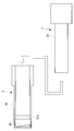
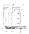
- FIGS. 1 and 2 An observation apparatus 1 according to a first embodiment of the present invention will be described below with reference to the drawings. As shown in FIGS. 1 and 2, the observation apparatus 1 according to the present embodiment observes cells S (see FIG. 10 and the like) floating in the culture solution (medium) W in the culture vessel 9. A camera unit 3, a tip unit 5 that is detachably attached to the tip of the camera unit 3, and an image analysis unit 7 that calculates the cell density in the culture medium W are provided.
- the culture vessel 9 is a bottomed cylindrical bioreactor whose upper surface is closed, and accommodates the cells S together with the culture medium W therein.
- the culture vessel 9 is covered with a cylindrical temperature adjustment jacket 11 that adjusts the temperature of the culture medium W.
- the culture vessel 9 is provided with a plurality of ports 9a for inserting various hoses 13 and probes 15 and an insertion port 9b for inserting the stirring mechanism 17 on the upper surface.
- ports 9 a are provided on the upper surface of the culture vessel 9. These ports 9a include a medium transport hose 13A for transporting the culture solution W, an air supply hose 13B for sending air to the culture solution W, a pH probe 15A for measuring the pH of the culture solution W, and the temperature of the culture solution W. A temperature measurement probe 15B for measuring the CO2 pressure and a CO2 pressure probe 15C for measuring the CO2 pressure of the culture medium W are inserted.
- the camera unit 3 can be inserted into the remaining one port 9a of the culture vessel 9 with the tip unit 5 attached.
- the stirring mechanism 17 includes a stirring shaft 17a inserted into the culture vessel 9 through the insertion port 9b of the culture vessel 9, and a plurality of stirring blades 17b provided on the stirring shaft 17a.
- a plurality of agitating blades 17b are arranged at intervals in the circumferential direction at three locations in the longitudinal direction of the agitating shaft 17a.
- the stirring mechanism 17 can stir the culture medium W by rotating the stirring shaft 17a and the stirring blade 17b around the longitudinal axis by a driving unit such as a motor (not shown). Then, the culture medium W is agitated by the agitating mechanism 17 to prevent the cells S from sticking to the inner surface of the culture vessel 9, and the cells S can be cultured while floating in the culture medium W.
- a driving unit such as a motor (not shown).
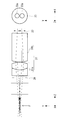
- the camera unit 3 has a light source 21, a light guide fiber 23 that guides illumination light emitted from the light source 21, and different viewpoints for the same cell S.
- a stereo optical system (stereo imaging optical system) 25 that forms two images with parallax viewed from each other, and an imaging device (stereo imaging optical system) that captures the two images formed by the stereo optical system 25, respectively.
- symbol K indicates a light emitting area.
- the light source 21 is disposed on the base end side of the housing 29.
- the light guide fiber 23 guides illumination light from the light source 21 to the tip of the housing 29.
- the stereo optical system 25 includes, in order from the distal end side, an objective optical system 31 that condenses the light from the cell S, a diaphragm opening 33 that divides the light collected by the objective optical system 31, and a diaphragm opening 33.
- a deflection prism 35 that deflects the divided light and an imaging optical system 37 that forms an image of the light deflected by the deflection prism 35 are provided.
- the stereo optical system 25 has, for example, a magnification of 4 and an NA of 0.089.
- the stereo optical system 25 has an actual field of view of 1.06 mm in the X direction and 0.6 mm in the Y direction.
- the Y direction is stereo.
- the arrangement direction of the viewpoints of the stereo optical system 25 is referred to as a stereo direction.
- a direction along the optical axis of the stereo optical system 25 is defined as a Z direction
- a direction orthogonal to the optical axis of the stereo optical system 25 and orthogonal to the stereo direction is defined as an X direction.
- the objective optical system 31 includes a lens component 31a obtained by cementing a biconcave lens and a biconvex lens, and a convex / concave lens 31b.
- the objective optical system 31 has a diameter of 5.5 mm.
- the objective optical system 31 has a working distance (WD) of 4 mm, for example.
- reference numeral F indicates the position of the best focus surface
- reference numeral 39 indicates a cover glass. In FIG. 7, chief rays are mainly displayed.
- the diaphragm aperture 33 is arranged at the pupil position as shown in FIG.
- two holes 33a having a diameter of 1.4 mm are provided at an interval in the stereo direction.
- the deflection prism 35 is formed by bonding a prism 35 ⁇ / b> A and a prism 35 ⁇ / b> B having a plane whose surface on the image sensor 27 side is inclined in a direction in which the thickness increases as the absolute value in the Y direction increases. Is.
- the inclination of the surface on the image sensor 27 side has, for example, an angle of 2.9 ° in the + Y direction and an angle of ⁇ 2.9 ° in the ⁇ Y direction with respect to the optical axis.
- a light-shielding coating 35a that does not transmit light is applied between the prisms 35A and 35B.
- a light shielding member may be provided between the prism 35A and the prism 35B.
- the imaging optical system 37 is composed of a biconcave lens 37a and a lens component 37b obtained by cementing the convex / concave lens and the biconvex lens.
- the imaging optical system 37 has a diameter of 11 mm.
- between the deflection prism 35 and the imaging optical system 37 and between the imaging optical system 37 and the imaging device 27, light passing through the + Y direction and light passing through the ⁇ Y direction Each is provided with a light shielding member 36 for preventing the two from mixing.
- the image sensor 27 is arranged on the most proximal side of the housing 29.
- the imaging element 27 has an imaging area of 4.28 mm in the X direction and 5.9 mm in the Y direction.
- the cell image information acquired by the image sensor 27 is sent to the image analysis unit 7.
- the tip unit 5 irradiates the cell S with illumination light at an angle in a direction intersecting the stereo direction and a substantially rectangular tube-shaped protective cover 41 into which the camera unit 3 is inserted. And a mirror (polarized illumination unit) 43.
- the tip unit 5 has a protective cover 41 sterilized, and can be replaced as a disposable part that is disposable after each use.
- the protective cover 41 has an opening window 41a that opens on both side surfaces facing in the width direction on the base end side with respect to the front end. These opening windows 41 a are arranged between the mirror 43 and the objective optical system 31 in a state where the camera unit 3 is inserted into the protective cover 41.
- the opening window 41a has a size that allows the cells S and the culture medium W to pass through the inside of the protective cover 41 in the width direction.
- These opening windows 41a are formed, for example, by dividing the protective cover 41 into a distal end side and a proximal end side in the longitudinal direction and connecting the distal end side and the proximal end side at two locations in the circumferential direction of the protective cover 41. It may be an opening.
- the mirror 43 is disposed at the distal end of the protective cover 41 so as to face the proximal end side. Further, the mirror 43 has a reflection surface having an inclination of 6.5 ° with respect to the optical axis of the objective optical system 31. For example, the mirror 43 reflects the illumination light guided by the light guide fiber 23 toward the objective optical system 31 of the camera unit 3 at an angle in a direction orthogonal to the stereo direction, thereby culturing. The cells S in the liquid W are incidentally illuminated.
- the image analysis unit 7 specifies the position of the cell S included in each of the two images acquired by the image sensor 27. Then, the image analysis unit 7 calculates the cell density in the culture medium W based on the number of cells S present in the predetermined region.
- the predetermined area is, for example, an in-focus range and is set in advance. In the present embodiment, for example, the distance from the best focus position is preferably in the range of Z ⁇ 0.2 mm in the Z direction of the predetermined area.
- the operation of the observation apparatus 1 In order to observe the cells S cultured while being suspended in the culture medium W in the culture vessel 9 by the observation device 1 having the above-described configuration, first, as shown in FIG. In this state, the camera unit 3 and the tip unit 5 are inserted into the culture medium W through the port 9a of the culture vessel 9.
- illumination light is generated from the light source 21 of the camera unit 3, the illumination light is guided by the light guide fiber 23, and the illumination light is emitted from the tip of the light guide fiber 23 toward the mirror 43 of the tip unit 5.
- the illumination light reflected by the mirror 43 is irradiated to the cell S that has entered the tip unit 5 through the opening window 41a while floating in the culture medium W.
- the transmitted light of the illumination light transmitted through the cell S enters the stereo optical system 25 of the camera unit 3.
- the transmitted light of the illumination light transmitted through the cell S is collected by the objective optical system 31, and then divided by the aperture opening 33 and deflected by the deflecting prism 35, respectively. Thereby, two images with parallax viewed from different viewpoints for each cell S are formed on the plurality of cells S floating in the culture medium W. Then, the imaged two images are taken by the image sensor 27.
- the image information of the two images acquired by the image sensor 27 is sent to the image analysis unit 7. Then, based on the image information input by the image analysis unit 7, as shown in FIG. 10, a plurality of cells S are two-dimensional with parallax as viewed from different viewpoints for each individual cell S. Two images, that is, an upper image and a lower image shown in FIG. 10 are generated.
- the position of each cell S included in the generated two images of the plurality of cells S is specified by the image analysis unit 7.
- the cell density in the culture solution W is calculated by the image analysis unit 7 based on the number of cells S present in the predetermined region.
- the stereo optical system 25 forms two images with parallax viewed from different viewpoints for each cell S on the plurality of cells S in the culture medium W, thereby obtaining an image sensor.
- the position of the same cell S in the Y direction is shifted in the opposite direction between the images of these two images acquired by the unit 27 according to the distance from the stereo optical system 25.
- the difference between the Y coordinates of two cell images on the imaging surface obtained by photographing the same cell S on the best focus plane F is ⁇ Y0, and the imaging surface obtained by photographing the cell S at an arbitrary Z position
- the difference between the Y coordinates of two cell images is defined as ⁇ Y
- the size of each cell S is 20 ⁇ m
- the refractive index of the cell S is 1.36
- the refractive index of the culture medium W is 1.332
- the size of the display image is 0.48 mm ⁇
- the case of 0.48 mm (0.12 mm ⁇ 0.12 mm in object side conversion) is shown. The same applies to FIG.
- the image analysis unit 7 can accurately identify the cells S included in the predetermined region and the cells S not included.
- the cell density in the culture medium W can be calculated.
- the observation apparatus 1 which concerns on this embodiment, the cell density in the culture solution W can be measured accurately irrespective of the shape, size, etc. of the culture vessel 9 to be used.
- the unit of Z is mm.
- the culture vessel 9 that is a bioreactor is exemplified as the culture vessel for culturing the cells S.
- the culture vessel may be a cell culture pack in addition to the bioreactor.
- the camera unit 3 and the tip unit 5 of the observation apparatus 1 are inserted into the cell culture pack and used. The same applies to the second embodiment and the third embodiment.
- the observation apparatus 1 according to the present embodiment is different from the first embodiment in the configuration of the stereo optical system 25.
- portions having the same configuration as those of the observation apparatus 1 according to the first embodiment described above are denoted by the same reference numerals and description thereof is omitted.
- the stereo optical system 25 of the present embodiment does not include the deflecting prism 35, and includes an objective optical system 31 that condenses the light from the cell S, and a diaphragm opening 33 that divides the light collected by the objective optical system 31. And an imaging optical system 45 for separately imaging the lights divided by the aperture 33.
- the imaging optical system 45 includes a concave / convex lens 45a, a lens component 45b obtained by joining a biconcave lens and a biconvex lens, and a convex / concave lens 45c.
- the concave / convex lens 45a, the lens component 45b, and the convex / concave lens 45c are composed of a left and right lens pair.
- a light shielding member 36 is sandwiched between each pair of lenses.
- the lens pairs of the concavo-convex lens 45a, the lens component 45b, and the convex / concave lens 45c are arranged such that their optical axes are spaced apart from each other on the left and right, and can transmit the light divided by the aperture opening 33.
- the observation apparatus 1 according to this embodiment including the stereo optical system 25 having the above configuration also has the same effect as that of the first embodiment.
- the observation apparatus 1 according to the present embodiment is different from the first embodiment in the configuration of the stereo optical system 25.
- portions having the same configuration as those of the observation apparatus 1 according to the first embodiment described above are denoted by the same reference numerals and description thereof is omitted.
- the stereo optical system 25 of the present embodiment includes a tip prism (prism) 47A that divides the light from the cell S into two images.
- the stereo optical system 25 includes a diaphragm opening 48 having a single opening that is not divided into two, instead of the diaphragm opening 33.
- the stereo optical system 25 has, for example, a magnification of 4 and an NA of 0.087.
- the stereo optical system 25 has a real field of view of 1.07 mm in the X direction and 0.5 mm in the Y direction.
- reference numeral 49a indicates a lens component in which a convex / concave lens and a biconvex lens are cemented
- reference numeral 49b indicates a biconvex lens
- reference numeral 49c indicates a concave / convex lens
- reference numeral 49d indicates a concave / convex lens and a concave / convex lens.
- a cemented lens component is shown, and reference numeral 47B denotes a proximal prism.
- the front end prism 47A and the base end prism 47B have a certain thickness in the depth direction of the paper surface of FIG.
- the tip prism 47A has an incident surface with an inclination angle of ⁇ 2 ° and an output surface with an inclination angle of 7 °, and is symmetrical with respect to the optical axis on the + Y side and the ⁇ Y side. Yes.
- the chief ray incident angle to the aperture opening 48 has inclinations in opposite directions on the + Y side and the ⁇ Y side, and a stereo optical system is realized.
- the base prism 47B has an entrance surface and an exit surface formed in parallel to each other, the entrance surface has an inclination angle of 7 °, and the exit surface has an inclination angle of 7 °.
- the proximal prism 47B is composed of a proximal prism 47B1 and a proximal prism B2 that are line-symmetric with respect to the optical axis on the + Y side and the ⁇ Y side.
- the proximal prism 47B is configured to simultaneously photograph a stereo image by one image sensor (not shown) by bringing the + Y side image and the ⁇ Y side image close to each other. Without the base prism 47B, the image position on the + Y side and the image position on the -Y side are too far apart in the Y direction, resulting in a wasteful area unnecessary for density analysis near the middle, that is, near the optical axis. Therefore, it is necessary to use a wider imaging area of the imaging element.
- a light shielding member 36 is provided between the cemented lens component 49d and the imaging device (not shown) to prevent the + Y side light beam and the ⁇ Y side light beam from being mixed.
- the observation apparatus 1 according to this embodiment including the stereo optical system 25 having the above configuration also has the same effect as that of the first embodiment.
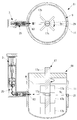
- An observation apparatus 51 according to the present embodiment is different from the first to third embodiments in that the light source 21 is disposed outside the camera unit 3, for example, as shown in FIG.
- portions having the same configuration as those of the observation apparatus 1 according to the first to third embodiments described above are denoted by the same reference numerals and description thereof is omitted.
- the stereo optical system 25 of the first embodiment described above will be exemplified and described.
- the stirring shaft 17a is formed of a hollow cylindrical member.
- the camera unit 3 does not include the light source 21 and the light guide fiber 23, and is housed in the stirring shaft 17a without being attached to the tip unit 5.
- the stirring shaft 17a has a parallel plate-like observation window 53 made of an optically transparent material.
- the observation window 53 is disposed, for example, between the first stirring blade 17b and the second stirring blade 17b from the tip side of the stirring shaft 17a.
- the stereo optical system 25 is disposed along the longitudinal direction of the stirring shaft 17a, and forms an image of light from the cells S that passes through the observation window 53 and enters the stirring shaft 17a. Further, the stereo optical system 25 does not rotate around the stirring shaft 17a.
- a right-angle prism 55 that deflects light incident from the observation window 53 into the stirring shaft 17a in the longitudinal direction of the stirring shaft 17a.
- the light incident on the stirring shaft 17 a from the observation window 53 is incident on the stereo optical system 25 by the right-angle prism 55.
- the light source 21 is disposed outside the culture vessel 9 and emits illumination light from the outside of the culture vessel 9 toward the observation window 53.
- the light source 21 is arranged with a height shifted from the observation window 53. Thereby, the cells S can be illuminated obliquely, and an image with improved contrast of the cells S can be acquired.
- the culture vessel 9 has a parallel plate-shaped illumination window 9c on the side surface that transmits illumination light emitted from the light source 21. Thereby, the illumination light emitted from the light source 21 passes through the illumination window 9c and is irradiated to the cells S in the culture medium W. Then, the transmitted light of the illumination light that has passed through the cell S passes through the observation window 53, is then deflected by the right-angle prism 55, and is incident on the stereo optical system 25.
- an image of the cell S is taken when the observation window 53 overlaps the incident position of the stereo optical system 25 while the stirring shaft 17a is rotating.
- the configuration can be simplified.
- the stereo optical system 25 does not interfere with the flow of the culture medium W and the cells S.
- a 45 ° mirror may be employed instead of the right-angle prism 55.
- the stereo optical system 25 may rotate around the stirring shaft 17a together with the stirring shaft 17a. With this configuration, an image of the cell S is taken when the incident positions of the observation window 53 and the stereo optical system 25 face the light source 21 while the stirring shaft 17a is rotating. In this case, the stereo optical system 25 rotates together with the stirring shaft 17a, so that the imaging region can follow the flow of the culture medium W and the cells S.
- the light source 21 may generate illumination light from the entire area in the circumferential direction outside the culture vessel 9 toward the observation window 53.
- the stereo optical system 25 may rotate around the stirring shaft 17a together with the stirring shaft 17a.
- the illumination window 9c may be formed over the entire area of the culture vessel 9 in the circumferential direction.
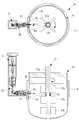
- the observation device 61 according to the present embodiment is different from the fourth embodiment in that the camera unit 3 is disposed outside the culture vessel 9.
- portions having the same configuration as those of the observation device 51 according to the above-described fourth embodiment are denoted by the same reference numerals and description thereof is omitted.
- the culture vessel 9 has a parallel plate-like observation window 63 made of an optically transparent material on the side surface.
- the stereo optical system 25 is disposed outside the culture vessel 9 and forms an image of light from the cell S that has passed through the observation window 63.
- a plurality of light sources 21 are attached to the stirring shaft 17a, and illumination light is emitted from each of the light sources 21 outward in the radial direction of the stirring shaft 17a.
- Each light source 21 is arranged so as to be shifted from the observation window 63 and the height.
- Each light source 21 is rotated around the stirring shaft 17a together with the stirring shaft 17a. Thereby, the illumination light emitted from each light source 21 is irradiated to the cell S in the culture solution W. Then, the transmitted light of the illumination light transmitted through the cell S passes through the observation window 63 and enters the stereo optical system 25.
- an image of the cell S is taken when any one of the light sources 21 faces the observation window 63 during the rotation of the stirring shaft 17a.
- the diameter of the stirring shaft 17a can be reduced by the amount that the stereo optical system 25 is not housed in the stirring shaft 17a, and the culture vessel 9 can be downsized.
- the stereo optical system 25 outside the culture vessel 9, the flow of the culture solution W and the cells S in the culture vessel 9 can be prevented from being disturbed by the stereo optical system 25. Moreover, the light from the cells S in the culture medium W irradiated with the illumination light passes through the parallel plate-like observation window 63 and enters the stereo optical system 25, so that the occurrence of aberration can be suppressed.
- a small light source such as an LED can be used as the light source 21. Further, by arranging the light source 21 so as to be shifted in height from the observation window 53, the cells S can be illuminated obliquely.
- the stirring shaft 17a may be hollow and the light source 21 may be housed in the stirring shaft 17a.
- the light source 21 may emit illumination light from the entire circumference in the circumferential direction of the stirring shaft 17a toward the outer side in the radial direction of the stirring shaft 17a while rotating around the stirring shaft 17a together with the stirring shaft 17a.
- the stirring shaft 17a may have an annular transmission window 65 made of an optically transparent material surrounding the light source 21.
- the transmission window 65 may have a comparative diffusion function that allows the transmitted illumination light to have various angle components.
- the illumination light emitted from the light source 21 and transmitted through the transmission window 65 of the stirring shaft 17a is applied to the cells S in the culture medium W. Then, the transmitted light of the illumination light transmitted through the cell S passes through the observation window 63 and enters the stereo optical system 25. In this case, while the light source 21 rotates together with the stirring shaft 17a, the illumination light is emitted from the entire circumference in the circumferential direction of the stirring shaft 17a toward the radially outward direction, so that one light source 21 can always shoot. .
- the light source 21 rotates with the stirring shaft 17a.
- the light source 21 does not rotate around the stirring shaft 17a and the observation window 63 is rotated. It is good also as emitting illumination light toward.
- the illumination light emitted from the light source 21 and transmitted through the transmission window 65 of the stirring shaft 17a is applied to the cells S in the culture medium W. Then, the transmitted light of the illumination light transmitted through the cell S passes through the observation window 63 and enters the stereo optical system 25. In this case, since the light source 21 is not rotated, the circuit connected to the light source 21 does not have to be complicated.
- the light source 21 may be arranged outside the culture vessel 9 and emit illumination light toward the observation window 63. Further, the light source 21 and the observation window 63 may be arranged to face each other in the radial direction of the stirring shaft 17a with the stirring shaft 17a interposed therebetween.
- the culture vessel 9 may have a parallel plate-shaped illumination window 9c that transmits the illumination light emitted from the light source 21. Furthermore, it is good also as forming the area
- the illumination light emitted from the light source 21 and transmitted through the illumination window 9c is transmitted through the light transmission member 17c of the stirring shaft 17a. Then, the illumination light is irradiated to the cells S in the culture medium W, and the transmitted light of the illumination light that has passed through the cells S passes through the observation window 63 and enters the stereo optical system 25.
- the light source 21 and the stereo optical system 25 are arranged outside the culture vessel 9 so that the light source 21 and the stereo optical system 25 do not interfere with the flow of the culture medium W and the cells S.
- the light source 21 may be arranged outside the culture vessel 9 and emit illumination light toward the stirring shaft 17a.
- the culture vessel 9 may have a parallel plate-like illumination window 9c that transmits illumination light emitted from the light source 21 on its side surface.
- the region arranged on the optical path of the illumination light of the stirring shaft 17 a may be formed by a reflection member 17 d made of a material that reflects the illumination light toward the observation window 63.
- the illumination light emitted from the light source 21 and transmitted through the illumination window 9c is reflected by the reflecting member 17d of the stirring shaft 17a. Then, the illumination light is irradiated to the cells S in the culture medium W, and the transmitted light of the illumination light that has passed through the cells S passes through the observation window 63 and enters the stereo optical system 25.
- the light source 21 and the stereo optical system 25 are arranged outside the culture vessel 9 so that the light source 21 and the stereo optical system 25 do not interfere with the flow of the culture medium W and the cells S.
- the light source 21 and the stereo optical system 25 can be disposed in the vicinity of the outside of the culture vessel 9, and space saving can be achieved.
- the light source 21, the illumination window 9c, and the observation window 63 are arranged opposite to each other with their positions shifted in the radial direction of the stirring shaft 17a. It is good. Further, the illumination light emitted from the light source 21 may pass through a position shifted in the longitudinal direction of the stirring shaft 17a with respect to the stirring blade 17b and enter the observation window 63.
- the illumination light emitted from the light source 21 and transmitted through the illumination window 9c is irradiated to the cells S in the culture medium W without being blocked by the stirring shaft 17a and the stirring blade 17b. Then, the transmitted light of the illumination light transmitted through the cell S passes through the observation window 63 and enters the stereo optical system 25. Therefore, except for the observation window 63 and the illumination window 9c, a simple configuration can be achieved as in the conventional culture vessel.
- the illumination light emitted from the light source 21 passes through a position shifted in the longitudinal direction of the stirring shaft 17a with respect to the stirring blade 17b.
- FIG. 5 at least a part of the stirring blade 17b is formed of an optically transparent material, and the illumination light emitted from the light source 21 passes through the region formed of the optically transparent material of the stirring blade 17b. It is good to do.
- the illumination light emitted from the light source 21 and transmitted through the illumination window 9c passes through the region formed of the optically transparent material of the stirring blade 17b. Then, the illumination light is irradiated to the cells S in the culture medium W, and the transmitted light of the illumination light that has passed through the cells S passes through the observation window 63 and enters the stereo optical system 25. Therefore, the cell density in a region corresponding to the depth where the stirring blade 17b is disposed in the culture vessel 9 can also be measured.
- the light source 21 may emit illumination light toward the stirring blade 17b.
- the region arranged on the optical path of the illumination light of the stirring blade 17b may be formed of a material that reflects the illumination light toward the observation window 63.
- the illumination light emitted from the light source 21 and transmitted through the illumination window 9c is reflected by the stirring blade 17b. Then, the illumination light is irradiated to the cells S in the culture medium W, and the transmitted light of the illumination light that has passed through the cells S passes through the observation window 63 and enters the stereo optical system 25.
- the light source 21 and the stereo optical system 25 are arranged outside the culture vessel 9 so that the light source 21 and the stereo optical system 25 do not interfere with the flow of the culture medium W and the cells S.
- the light source 21 and the stereo optical system 25 can be disposed in the vicinity of the outside of the culture vessel 9, and space saving can be achieved.
- the light source 21 may be disposed outside the culture vessel 9 and emit illumination light into the culture vessel 9.
- the culture vessel 9 deflects the illumination light emitted from the light source 21 in the direction along the inner peripheral surface in the culture vessel 9, and the deflection in the culture solution W after being deflected by the first prism 57. It is good also as having the 2nd prism 59 which deflects the transmitted light of the illumination light irradiated to the cell S toward the outer side of the culture container 9, respectively.
- the stereo optical system 25 may be disposed outside the culture vessel 9 and may form an image of the light emitted to the outside of the culture vessel 9 by the second prism 59.
- the flow of the culture solution W and the cells S in the culture vessel 9 is not disturbed by the stereo optical system 25.
- the second prism 59 by deflecting the light from the cells S by the second prism 59, the light of the cells S emitted from the direction intersecting the optical axis of the stereo optical system 25 can be incident on the stereo optical system 25.
- the illumination light does not cross inside the culture vessel 9, and the distance between the first prism 57 and the second prism 59 can be shortened.
- the volume of the culture solution W in the optical path of the illumination light is small and the number of cells S is small, it is possible to suppress the influence of the scattering of the illumination light and obtain an image with high contrast.
- the culture vessel 9 may have an observation window 63 on the bottom surface.
- the light source 21 may be disposed on the upper surface of the culture vessel 9 and emit illumination light toward the observation window 63.
- the stereo optical system 25 may be disposed below the bottom surface of the culture vessel 9 and may form an image of light from the cells S that has passed through the observation window 63 and exited from the culture vessel 9.
- the stereo optical system 25 may be arranged along the bottom surface of the culture vessel 9. Further, between the observation window 63 and the stereo optical system 25, a right-angle prism 55 that makes the light transmitted through the observation window 63 incident on the stereo optical system 25 by deflecting the light that passes through the bottom surface of the culture vessel 9 is disposed. It is good as well.
- the height position of the observation window 63 of the stereo optical system 25 and the height position of the light source 21 are different from each other. Since oblique illumination images can be acquired by illuminating light incident obliquely with respect to the optical axis, the light source 21 may be shifted from the optical axis of the stereo optical system 25.
- the stereo optical system 25 may be arranged to be inclined with respect to the optical axis of the illumination light emitted from the light source 21.
Abstract
An observation device comprises: a stereo optical system (25) which forms two images of cells suspended in a liquid culture medium in a culture container, said two images being acquired by observing the same cells from different viewpoints and showing a disparity; an image pickup element (27) which picks up the individual two images formed by the stereo optical system (25); and an image analysis unit which specifies the positions of cells in the individual two images picked up by the image pickup element (27) and calculates the cell density in the liquid culture medium depending on the number of cells present in a definite area.
Description
本発明は、観察装置に関するものである。
The present invention relates to an observation apparatus.
近年、iPS細胞(人工多能性幹細胞)をはじめとする再生医療分野において、細胞培養のスケールアップが望まれている。細胞の大量生産に向けて、従来のウェルプレートやディッシュと呼ばれる容器を用いた接着培養から、バイオリアクタと呼ばれる浮遊培養容器を用いた浮遊培養に変わりつつある。浮遊培養容器を用いた浮遊培養は、浮遊培養容器内において液体を攪拌することによって細胞を液体中に浮遊させた状態で培養する。
In recent years, scale-up of cell culture is desired in the field of regenerative medicine including iPS cells (artificial pluripotent stem cells). Toward mass production of cells, conventional adhesion culture using a container called a well plate or dish is changing to suspension culture using a suspension culture container called a bioreactor. In suspension culture using a suspension culture vessel, cells are cultured in a state where the cells are suspended in the liquid by stirring the fluid in the suspension culture vessel.
浮遊培養容器を用いた細胞の観察方法としては、例えば、特許文献1に記載された方法が知られている。特許文献1に記載の方法は、浮遊培養容器の外側に配置された照明装置および撮像装置により、浮遊培養容器内の液体中に浮遊している細胞の画像を取得する。そして、画像解析と予め入力されたパラメータとを用いた演算処理により、細胞の粒径分布と総細胞数とを算出する。
As a method for observing cells using a floating culture vessel, for example, the method described in Patent Document 1 is known. In the method described in Patent Document 1, an image of cells floating in a liquid in a suspension culture vessel is acquired by an illumination device and an imaging device arranged outside the suspension culture vessel. Then, the particle size distribution of cells and the total number of cells are calculated by an arithmetic process using image analysis and parameters input in advance.
しかしながら、浮遊培養容器は用途に応じて多種多様な形状、大きさ、攪拌羽根および材質等があるため、全ての浮遊培養容器に対して、浮遊培養容器の外側から常に同じ向きで同じ方向から、同じ範囲を照明することによって細胞を観察するということができない。そのため、使用する浮遊培養容器によっては、安定した撮影条件で画像を得ることが難しく、画像解析の精度が大きく低下してしまう虞がある。特に、細胞数や細胞密度の解析に至っては、照明範囲等の撮影条件の変化により、細胞密度の等の精度が大きく低下してしまうという問題がある。
However, the suspension culture vessel has various shapes, sizes, stirring blades and materials depending on the application, so for all suspension culture vessels, always from the same direction in the same direction from the outside of the suspension culture vessel, It is not possible to observe cells by illuminating the same area. Therefore, depending on the floating culture vessel used, it is difficult to obtain an image under stable photographing conditions, and the accuracy of image analysis may be greatly reduced. In particular, the analysis of the number of cells and the cell density has a problem that the accuracy of the cell density and the like greatly decreases due to a change in imaging conditions such as an illumination range.
本発明は、上述した事情に鑑みてなされたものであって、浮遊培養中の培養液内の細胞密度を精度よく測定することができる観察装置を提供することを目的としている。
The present invention has been made in view of the above-described circumstances, and an object thereof is to provide an observation apparatus that can accurately measure the cell density in a culture solution during suspension culture.
上記目的を達成するために、本発明は以下の手段を提供する。
本発明の一態様は、培養容器内の培養液中に浮遊する細胞を撮像するステレオ撮像光学系と、該ステレオ撮像光学系によって取得された複数の画像に基づいて、前記細胞の細胞密度を算出する画像解析部とを備える観察装置である。 In order to achieve the above object, the present invention provides the following means.
One embodiment of the present invention is a stereo imaging optical system that images a cell floating in a culture solution in a culture vessel, and the cell density of the cell is calculated based on a plurality of images acquired by the stereo imaging optical system. And an image analysis unit that performs the observation.
本態様によれば、ステレオ撮像光学系により、ステレオ撮像光学系からの距離に応じて同一の細胞の位置がずれた複数の画像が取得される。したがって、これらの画像に基づいて、各細胞の3次元的な位置が分かるので、画像解析部により、培養液内の細胞密度を精度よく算出することができる。
According to this aspect, the stereo imaging optical system acquires a plurality of images in which the positions of the same cells are shifted according to the distance from the stereo imaging optical system. Therefore, since the three-dimensional position of each cell is known based on these images, the cell density in the culture solution can be accurately calculated by the image analysis unit.
上記態様に係る観察装置は、前記ステレオ撮像光学系が、前記培養液中に浮遊している同一の細胞に対して、異なる視点から見た互いに視差がある2つの像を結像させるステレオ光学系と、該ステレオ光学系によって結像された2つの前記像をそれぞれ撮影する撮像素子とを備え、前記画像解析部が、前記撮像素子によって取得された2つの前記像の各画像に含まれている前記細胞の位置を特定し、所定の領域内に存在する前記細胞の数に基づいて、前記細胞密度を算出することとしてもよい。
The observation apparatus according to the above aspect is a stereo optical system in which the stereo imaging optical system forms two images with parallax viewed from different viewpoints with respect to the same cell floating in the culture medium. And an image sensor that captures each of the two images formed by the stereo optical system, and the image analysis unit is included in each image of the two images acquired by the image sensor The cell density may be calculated based on the number of the cells present in a predetermined region by specifying the position of the cells.
この構成によって、ステレオ光学系により、培養液中の同一の細胞に対して、異なる視点から見た互いに視差がある2つの像を結像させることによって、撮像素子により取得されるこれら2つの像の画像間で、ステレオ光学系からの距離に応じて同一の細胞の位置がずれる。すなわち、ステレオ光学系からの距離が近い細胞ほど画像間のずれ量が小さく、遠い細胞ほど画像間のずれ量が大きくなる。
With this configuration, two images with parallax viewed from different viewpoints are formed on the same cell in the culture solution by the stereo optical system, so that these two images acquired by the image sensor can be obtained. Between the images, the position of the same cell is shifted according to the distance from the stereo optical system. That is, as the distance from the stereo optical system is shorter, the shift amount between images is smaller, and as the cell is farther, the shift amount between images is larger.
したがって、各細胞の3次元的な位置が分かるので、画像解析部により、所定の領域内に含まれる細胞と含まれない細胞とを正確に区別して、培養液内の細胞密度を算出することができる。よって、使用する培養容器の形状および大きさ等に関わらず、浮遊培養中の培養液内の細胞密度を精度よく測定することができる。
Therefore, since the three-dimensional position of each cell is known, the image analysis unit can accurately distinguish between cells included in a predetermined region and cells not included, and calculate the cell density in the culture solution. it can. Therefore, the cell density in the culture solution during suspension culture can be accurately measured regardless of the shape and size of the culture vessel used.
上記態様に係る観察装置は、前記ステレオ光学系が、前記細胞からの光を集光する対物光学系と、該対物光学系により集光された光を分割する絞り開口部と、該絞り開口部により分割された光を偏向するプリズムとを備えることとしてもよい。
In the observation apparatus according to the above aspect, the stereo optical system includes an objective optical system that condenses light from the cells, an aperture opening that divides the light collected by the objective optical system, and the aperture opening It is good also as providing the prism which deflects the light divided | segmented by (3).
上記態様に係る観察装置は、前記ステレオ光学系が、前記細胞からの光を集光する対物光学系と、該対物光学系により集光された光を分割する絞り開口部と、該絞り開口部により分割された光をそれぞれ別個に結像させる結像光学系とを備えることとしてもよい。
In the observation apparatus according to the above aspect, the stereo optical system includes an objective optical system that condenses light from the cells, an aperture opening that divides the light collected by the objective optical system, and the aperture opening It is good also as providing the imaging optical system which images each light divided | segmented by 1 separately.
上記態様に係る観察装置は、前記ステレオ光学系が、前記細胞からの光を集光することによって2つの前記像に分割するプリズムを備えることとしてもよい。
In the observation device according to the aspect described above, the stereo optical system may include a prism that divides the light from the cells into two images.
上記態様に係る観察装置は、前記ステレオ光学系の前記視点の配列方向に対して交差する方向に角度を付けて前記細胞に照明光を照射する偏射照明部を備えることとしてもよい。
この構成によって、培養液中と細胞内との屈折率が異なるため、培養液と細胞との境界で光が曲げられる。この場合において、瞳の外側を通る方向に光が曲がった部分は像面で暗くなり、瞳の内側を通る方向に光が曲がった部分は像面で明るくなる。したがって、細胞のコントラストを向上した画像を取得することができる。 The observation apparatus according to the above aspect may include an oblique illumination unit that irradiates the cell with illumination light at an angle in a direction intersecting the arrangement direction of the viewpoints of the stereo optical system.
With this configuration, the refractive index is different between the culture solution and the inside of the cell, so that light is bent at the boundary between the culture solution and the cell. In this case, the portion where the light is bent in the direction passing through the outside of the pupil becomes dark on the image plane, and the portion where the light is bent in the direction passing through the inside of the pupil becomes bright on the image plane. Therefore, an image with improved cell contrast can be obtained.
上記態様に係る観察装置は、光学的に透明な材質からなる平行平板状の観察窓を側面に有する前記培養容器を備え、前記ステレオ光学系が、前記培養容器の外側に配置され、前記細胞から前記観察窓を透過して前記培養容器外に出射された光を結像させることとしてもよい。
The observation apparatus according to the above aspect includes the culture vessel having a parallel plate-like observation window made of an optically transparent material on a side surface, and the stereo optical system is disposed outside the culture vessel, The light emitted through the observation window and emitted outside the culture vessel may be imaged.
この構成によって、培養容器の培養液や細胞の流れがステレオ光学系によって邪魔されずに済む。この場合において、細胞からの光を平行平板状の観察窓を透過させてステレオ光学系に入射させることにより、収差の発生を抑制することができる。
With this configuration, the culture solution and cell flow in the culture vessel are not disturbed by the stereo optical system. In this case, the occurrence of aberration can be suppressed by allowing light from the cells to pass through the parallel plate-like observation window and enter the stereo optical system.
上記態様に係る観察装置は、前記細胞からの光を偏向することによって前記培養容器外に出射するプリズムを側面に有する前記培養容器を備え、前記ステレオ光学系が、前記培養容器の外側に配置され、前記プリズムによって前記培養容器外に出射された光を結像させることとしてもよい。
The observation apparatus according to the above aspect includes the culture container having a prism on the side surface that emits light from the cell by deflecting light from the cell, and the stereo optical system is disposed outside the culture container. The light emitted outside the culture vessel may be imaged by the prism.
この構成によって、培養容器の培養液や細胞の流れがステレオ光学系によって邪魔されずに済む。この場合において、細胞からの光をプリズムによって偏向することにより、ステレオ光学系の光軸に交差する方向から発せられる細胞の光をステレオ光学系に入射させることができる。
With this configuration, the culture solution and cell flow in the culture vessel are not disturbed by the stereo optical system. In this case, by deflecting the light from the cells with the prism, the light of the cells emitted from the direction intersecting the optical axis of the stereo optical system can be made incident on the stereo optical system.
上記態様に係る観察装置は、前記培養容器内を該培養容器の深さ方向に延びる中空の攪拌軸と、該攪拌軸回りに回転する攪拌翼とを備え、該攪拌翼が前記攪拌軸回りに回転することによって前記培養液を攪拌する攪拌機構とを備え、前記攪拌軸が、光学的に透明な材質からなる平行平板状の観察窓を有し、前記ステレオ光学系が、前記攪拌軸内に収納され、前記観察窓を透過して前記攪拌軸内に入射する前記細胞からの光を結像させることとしてもよい。
この構成によって、攪拌機構の攪拌軸内のスペースを利用して、培養容器内にステレオ光学系を配置することができる。 The observation apparatus according to the above aspect includes a hollow stirring shaft extending in the depth direction of the culture vessel in the culture vessel, and a stirring blade rotating around the stirring shaft, and the stirring blade is around the stirring shaft. A stirring mechanism for stirring the culture medium by rotating, the stirring shaft has a parallel plate-like observation window made of an optically transparent material, and the stereo optical system is disposed in the stirring shaft. The light from the cells that are stored and pass through the observation window and enter the stirring shaft may be imaged.
With this configuration, the stereo optical system can be arranged in the culture vessel using the space in the stirring shaft of the stirring mechanism.
上記態様に係る観察装置は、前記攪拌軸の径方向外方から前記観察窓に向けて照明光を発する光源を備え、前記ステレオ光学系が、前記攪拌軸回りに回転しないこととしてもよい。
この構成によって、攪拌軸の回転中において、観察窓がステレオ光学系の入射位置に重なったときに撮影される。この場合において、ステレオ光学系が回転しないので、構成をシンプルにすることができる。また、攪拌軸内にステレオ光学系を収納することによって、ステレオ光学系が培養液および細胞の流れの邪魔にならずに済む。 The observation apparatus according to the above aspect may include a light source that emits illumination light from the radially outer side of the stirring shaft toward the observation window, and the stereo optical system may not rotate around the stirring shaft.
With this configuration, an image is taken when the observation window overlaps the incident position of the stereo optical system while the stirring shaft is rotating. In this case, since the stereo optical system does not rotate, the configuration can be simplified. Further, by housing the stereo optical system in the stirring shaft, the stereo optical system can be prevented from interfering with the flow of the culture solution and the cells.
上記態様に係る観察装置は、前記攪拌軸の径方向外方から前記観察窓に向けて照明光を発する光源を備え、前記ステレオ光学系が、前記攪拌軸とともに該攪拌軸回りに回転することとしてもよい。
この構成によって、攪拌軸の回転中において、観察窓およびステレオ光学系の入射位置が光源と対向したときに撮影される。この場合において、ステレオ光学系が攪拌軸と共に回転することによって、培養液および細胞の流れに撮影領域を追従させることができる。 The observation apparatus according to the above aspect includes a light source that emits illumination light from the radially outer side of the stirring shaft toward the observation window, and the stereo optical system rotates around the stirring shaft together with the stirring shaft. Also good.
With this configuration, an image is taken when the incident position of the observation window and the stereo optical system faces the light source while the stirring shaft is rotating. In this case, when the stereo optical system rotates together with the stirring shaft, the imaging region can follow the flow of the culture solution and the cells.
上記態様に係る観察装置は、前記攪拌軸の径方向外方における周方向の全域から前記観察窓に向けて照明光を発する光源を備え、前記ステレオ光学系が、前記攪拌軸とともに該攪拌軸回りに回転することとしてもよい。
この構成によって、光源から照明光を発生させるタイミングと観察窓およびステレオ光学系の入射位置を光源に対向させるタイミングとを合わせる必要がなく、常時撮影することができる。 The observation apparatus according to the above aspect includes a light source that emits illumination light toward the observation window from the entire circumferential direction outside the stirring shaft in the radial direction, and the stereo optical system and the stirring shaft rotate around the stirring shaft. It is good also as rotating.
With this configuration, it is not necessary to match the timing at which illumination light is generated from the light source and the timing at which the incident positions of the observation window and the stereo optical system are opposed to the light source, so that continuous shooting can be performed.
上記態様に係る観察装置は、前記培養容器内を該培養容器の深さ方向に延びる攪拌軸と、該攪拌軸回りに回転する攪拌翼とを備え、該攪拌翼が前記攪拌軸回りに回転することによって前記培養液を攪拌する攪拌機構と、前記攪拌軸に該攪拌軸と共に回転可能に設けられ、前記攪拌軸の径方向外方に向けて照明光を発する複数の光源とを備え、これら複数の光源が、前記攪拌軸の周方向に配列されていることとしてもよい。
The observation apparatus according to the above aspect includes a stirring shaft extending in the depth direction of the culture vessel in the culture vessel, and a stirring blade that rotates about the stirring shaft, and the stirring blade rotates about the stirring shaft. A stirring mechanism that stirs the culture solution, and a plurality of light sources that are provided on the stirring shaft so as to be rotatable together with the stirring shaft and emit illumination light radially outward of the stirring shaft. These light sources may be arranged in the circumferential direction of the stirring shaft.
この構成によって、攪拌軸の回転中において、いずれかの光源が観察窓と対向したときに撮影される。この場合において、ステレオ光学系を攪拌軸内に収納しない分だけ、攪拌軸を細径化することができる。
This configuration allows a picture to be taken when any light source faces the observation window while the stirring shaft is rotating. In this case, the diameter of the stirring shaft can be reduced by the amount that the stereo optical system is not housed in the stirring shaft.
上記態様に係る観察装置は、前記培養容器内を該培養容器の深さ方向に延びる中空の攪拌軸と、該攪拌軸回りに回転する攪拌翼とを備え、該攪拌翼が前記攪拌軸回りに回転することによって前記培養液を攪拌する攪拌機構と、前記攪拌軸内に収納され、該攪拌軸と共に回転しながら前記攪拌軸の周方向の全周から径方向外方に向けて照明光を発する光源とを備え、前記攪拌軸が、前記光源の周囲を囲む光学的に透明な材質からなる環状の透過窓を有することとしてもよい。
The observation apparatus according to the above aspect includes a hollow stirring shaft extending in the depth direction of the culture vessel in the culture vessel, and a stirring blade rotating around the stirring shaft, and the stirring blade is around the stirring shaft. An agitation mechanism that agitates the culture medium by rotating, and is stored in the agitation shaft, and emits illumination light from the entire circumference in the circumferential direction of the agitation shaft toward the radially outer side while rotating together with the agitation shaft A light source, and the stirring shaft may have an annular transmission window made of an optically transparent material surrounding the light source.
この構成によって、光源から発せられて攪拌軸の透過窓を透過した照明光が、培養液中の細胞に照射される。そして、細胞を透過した照明光の透過光が、培養容器の観察窓を透過してステレオ光学系に入射される。この場合において、光源が攪拌軸と共に攪拌軸回りに回転しながら、攪拌軸の周方向の全周から径方向外方に向けて照明光を発することによって、1つの光源で常時撮影することができる。
With this configuration, the illumination light emitted from the light source and transmitted through the transmission window of the stirring shaft is irradiated to the cells in the culture solution. And the transmitted light of the illumination light which permeate | transmitted the cell permeate | transmits the observation window of a culture container, and injects into a stereo optical system. In this case, it is possible to always shoot with one light source by emitting illumination light from the entire circumference in the circumferential direction of the stirring shaft to the radially outward direction while the light source rotates around the stirring shaft together with the stirring shaft. .
上記態様に係る観察装置は、前記培養容器内を該培養容器の深さ方向に延びる中空の攪拌軸と、該攪拌軸回りに回転する攪拌翼とを備え、該攪拌翼が前記攪拌軸回りに回転することによって前記培養液を攪拌する攪拌機構と、該攪拌機構の前記攪拌軸内に収納され、前記観察窓に向けて照明光を発する光源とを備え、前記攪拌軸が、前記光源の周囲を囲む光学的に透明な材質からなる環状の透過窓を有し、前記光源が、前記攪拌軸回りに回転しないこととしてもよい。
The observation apparatus according to the above aspect includes a hollow stirring shaft extending in the depth direction of the culture vessel in the culture vessel, and a stirring blade rotating around the stirring shaft, and the stirring blade is around the stirring shaft. An agitation mechanism for agitating the culture medium by rotating; and a light source housed in the agitation shaft of the agitation mechanism and emitting illumination light toward the observation window, the agitation axis surrounding the light source And an annular transmission window made of an optically transparent material, and the light source may not rotate around the stirring axis.
この構成によって、光源から発せられた照明光が、攪拌軸の透過窓を透過して培養容器内の培養液を経由した後、培養容器の観察窓を透過してステレオ光学系に入射される。この場合において、光源を回転させないので、光源に接続する回路が複雑にならなくて済む。
With this configuration, the illumination light emitted from the light source passes through the transmission window of the stirring shaft and passes through the culture solution in the culture vessel, and then passes through the observation window of the culture vessel and enters the stereo optical system. In this case, since the light source is not rotated, the circuit connected to the light source does not have to be complicated.
上記態様に係る観察装置は、前記培養容器内を該培養容器の深さ方向に延びる攪拌軸と、該攪拌軸回りに回転する攪拌翼とを備え、該攪拌翼が前記攪拌軸回りに回転することによって前記培養液を攪拌する攪拌機構と、前記培養容器の外側に、前記攪拌軸を挟んで該攪拌軸の径方向に前記観察窓と対向して配置され、前記観察窓に向けて照明光を発する光源とを備え、前記培養容器が、前記光源から発せられた前記照明光を透過させる平行平板状の照明窓を前記側面に有し、前記攪拌軸の前記照明光の光路上に配置される領域が光学的に透明な材質によって形成されていることとしてもよい。
The observation apparatus according to the above aspect includes a stirring shaft extending in the depth direction of the culture vessel in the culture vessel, and a stirring blade that rotates about the stirring shaft, and the stirring blade rotates about the stirring shaft. An agitating mechanism for agitating the culture medium, and arranged outside the culture vessel, opposed to the observation window in a radial direction of the agitation shaft across the agitation shaft, and illuminating light toward the observation window And the culture vessel has a parallel plate-like illumination window that transmits the illumination light emitted from the light source on the side surface, and is disposed on the optical path of the illumination light of the stirring shaft. The area to be formed may be formed of an optically transparent material.
この構成によって、光源から発せられて照明窓を透過した照明光が、培養容器内において攪拌軸の光学的に透明な領域を透過した後、光源に対して攪拌軸の径方向に対向して配置された観察窓を透過してステレオ光学系に入射される。この場合において、光源およびステレオ光学系を培養容器の外側に配置することによって、これら光源およびステレオ光学系が培養液および細胞の流れの邪魔にならずに済む。
With this configuration, the illumination light emitted from the light source and transmitted through the illumination window passes through the optically transparent region of the agitation shaft in the culture vessel, and is then disposed opposite the light source in the radial direction of the agitation shaft. Then, the light passes through the observation window and enters the stereo optical system. In this case, by arranging the light source and the stereo optical system outside the culture vessel, the light source and the stereo optical system do not interfere with the flow of the culture solution and the cells.
上記態様に係る観察装置は、前記培養容器内を該培養容器の深さ方向に延びる攪拌軸と、該攪拌軸回りに回転する攪拌翼とを備え、該攪拌翼が前記攪拌軸回りに回転することによって前記培養容器内の前記培養液を攪拌する攪拌機構と、前記培養容器の外側に配置され、前記攪拌軸に向けて照明光を発する光源とを備え、前記培養容器が、前記光源から発せられた前記照明光を透過させる平行平板状の照明窓を前記側面に有し、前記攪拌軸の前記照明光の光路上に配置される領域が、前記照明光を前記観察窓に向けて反射する材質によって形成されていることとしてもよい。
The observation apparatus according to the above aspect includes a stirring shaft extending in the depth direction of the culture vessel in the culture vessel, and a stirring blade that rotates about the stirring shaft, and the stirring blade rotates about the stirring shaft. An agitation mechanism for agitating the culture solution in the culture vessel, and a light source disposed outside the culture vessel and emitting illumination light toward the agitation shaft, wherein the culture vessel emits from the light source. A parallel plate-shaped illumination window that transmits the illumination light is provided on the side surface, and a region arranged on the optical path of the illumination light on the stirring shaft reflects the illumination light toward the observation window. It may be formed of a material.
この構成によって、光源から発せられて照明窓を透過した照明光が、培養容器内において攪拌軸の反射する領域によって反された後、観察窓を透過してステレオ光学系に入射される。この場合において、光源およびステレオ光学系を培養容器の外側に配置することによって、これら光源およびステレオ光学系が培養液および細胞の流れの邪魔にならずに済む。また、培養容器の外側において光源とステレオ光学系を近接した位置に配置することができ、省スペース化を図ることができる。
With this configuration, the illumination light emitted from the light source and transmitted through the illumination window is deflected by the region reflected by the stirring shaft in the culture vessel, and then passes through the observation window and enters the stereo optical system. In this case, by arranging the light source and the stereo optical system outside the culture vessel, the light source and the stereo optical system do not interfere with the flow of the culture solution and the cells. In addition, the light source and the stereo optical system can be arranged close to each other on the outside of the culture vessel, and space saving can be achieved.
上記態様に係る観察装置は、前記培養容器内を該培養容器の深さ方向に延びる攪拌軸と、該攪拌軸回りに回転する攪拌翼とを備え、該攪拌翼が前記攪拌軸回りに回転することによって前記培養液を攪拌する攪拌機構と、前記培養容器の外側において、前記攪拌機構を挟み、かつ、前記攪拌軸の径方向に位置をずらして前記観察窓に対向して配置され、前記観察窓に向けて照明光を発する光源とを備え、前記培養容器が、前記光源から発せられた前記照明光を透過させる平行平板状の照明窓を前記側面に有し、前記光源から発せられた前記照明光が、前記攪拌翼に対して前記攪拌軸の長手方向にずれた位置を通過して前記観察窓に入射されることとしてもよい。
The observation apparatus according to the above aspect includes a stirring shaft extending in the depth direction of the culture vessel in the culture vessel, and a stirring blade that rotates about the stirring shaft, and the stirring blade rotates about the stirring shaft. An agitating mechanism for agitating the culture solution, and arranged outside the culture vessel so as to sandwich the agitating mechanism and be displaced in the radial direction of the agitation shaft to face the observation window. A light source that emits illumination light toward the window, and the culture vessel has a parallel plate-shaped illumination window that transmits the illumination light emitted from the light source on the side surface, and the light emitted from the light source The illumination light may be incident on the observation window through a position shifted in the longitudinal direction of the stirring shaft with respect to the stirring blade.
この構成によって、光源から発せられて照明窓を透過した照明光が、攪拌軸および攪拌翼によって遮られることなく培養容器内を通過した後、観察窓を透過してステレオ光学系に入射される。したがって、観察窓および照明窓以外は、従来の培養容器と同様にシンプルな構成にすることができる。
With this configuration, the illumination light emitted from the light source and transmitted through the illumination window passes through the culture vessel without being blocked by the stirring shaft and the stirring blade, and then passes through the observation window and enters the stereo optical system. Therefore, except for the observation window and the illumination window, a simple configuration can be achieved as in the conventional culture vessel.
上記態様に係る観察装置は、前記培養容器内を該培養容器の深さ方向に延びる攪拌軸と、該攪拌軸回りに回転する攪拌翼とを備え、該攪拌翼が前記攪拌軸回りに回転することによって前記培養液を攪拌する攪拌機構と、前記培養容器の外側において、前記攪拌機構を挟み、かつ、前記攪拌軸の径方向に位置をずらして前記観察窓に対向して配置され、前記観察窓に向けて照明光を発する光源とを備え、前記培養容器が、前記光源から発せられた前記照明光を透過させる平行平板状の照明窓を有し、前記攪拌翼が、少なくとも一部が光学的に透明な材質によって形成され、前記光源から発せられた前記照明光が、前記攪拌翼の前記光学的に透明な材質によって形成された領域を透過して、前記観察窓に入射されることとしてもよい。
The observation apparatus according to the above aspect includes a stirring shaft extending in the depth direction of the culture vessel in the culture vessel, and a stirring blade that rotates about the stirring shaft, and the stirring blade rotates about the stirring shaft. An agitating mechanism for agitating the culture solution, and arranged outside the culture vessel so as to sandwich the agitating mechanism and be displaced in the radial direction of the agitation shaft to face the observation window. A light source that emits illumination light toward the window, the culture vessel has a parallel plate-shaped illumination window that transmits the illumination light emitted from the light source, and the stirring blade is at least partially optical. The illumination light emitted from the light source is transmitted through a region formed of the optically transparent material of the stirring blade and is incident on the observation window. Also good.
この構成によって、光源から発せられて照明窓を透過した照明光が、攪拌翼の光学的に透明な領域を透過した後、観察窓を透過してステレオ光学系に入射される。したがって、培養容器内において、攪拌翼が配置されている深さに相当する領域の細胞密度も測定することができる。
With this configuration, the illumination light emitted from the light source and transmitted through the illumination window passes through the optically transparent region of the stirring blade, and then passes through the observation window and enters the stereo optical system. Therefore, the cell density in a region corresponding to the depth at which the stirring blade is disposed in the culture vessel can also be measured.
上記態様に係る観察装置は、前記培養容器内を該培養容器の深さ方向に延びる攪拌軸と、該攪拌軸回りに回転する攪拌翼とを備え、該攪拌翼が前記攪拌軸回りに回転することによって前記培養容器内の前記培養液を攪拌する攪拌機構と、前記培養容器の外側に配置され、前記攪拌翼に向けて照明光を発する光源とを備え、前記培養容器が、前記光源から発せられた前記照明光を透過させる平行平板状の照明窓を前記側面に有し、前記攪拌翼の前記照明光の光路上に配置される領域が、前記照明光を前記観察窓に向けて反射する材質によって形成されていることとしてもよい。
The observation apparatus according to the above aspect includes a stirring shaft extending in the depth direction of the culture vessel in the culture vessel, and a stirring blade that rotates about the stirring shaft, and the stirring blade rotates about the stirring shaft. An agitation mechanism for agitating the culture solution in the culture vessel, and a light source disposed outside the culture vessel and emitting illumination light toward the agitation blade, wherein the culture vessel emits from the light source. A parallel plate-shaped illumination window that transmits the illumination light is provided on the side surface, and a region disposed on the optical path of the illumination light of the stirring blade reflects the illumination light toward the observation window. It may be formed of a material.
この構成によって、光源から発せられて照明窓を透過した照明光が、攪拌翼によって反された後、観察窓を透過してステレオ光学系に入射される。この場合において、光源およびステレオ光学系を培養容器の外側に配置することによって、これら光源およびステレオ光学系が培養液および細胞の流れの邪魔にならずに済む。また、培養容器の外側において光源とステレオ光学系を近接した位置に配置することができ、省スペース化を図ることができる。
With this configuration, the illumination light emitted from the light source and transmitted through the illumination window is deflected by the stirring blade and then transmitted through the observation window and incident on the stereo optical system. In this case, by arranging the light source and the stereo optical system outside the culture vessel, the light source and the stereo optical system do not interfere with the flow of the culture solution and the cells. In addition, the light source and the stereo optical system can be arranged close to each other on the outside of the culture vessel, and space saving can be achieved.
上記態様に係る観察装置は、光学的に透明な材質からなる平行平板状の観察窓を底面に有する前記培養容器と、該培養容器の上面に配置され、前記観察窓に向けて照明光を発する光源とを備え、前記ステレオ光学系が、前記培養容器の外側に配置され、前記細胞から前記観察窓を透過して前記培養容器外に出射された光を結像させることとしてもよい。
この構成によって、培養容器の培養液や細胞の流れがステレオ光学系によって邪魔されずに済む。また、培養容器の形状をシンプルにすることができる。 The observation apparatus according to the above aspect is arranged on the top surface of the culture vessel having a parallel plate-like observation window made of an optically transparent material on the bottom surface, and emits illumination light toward the observation window. A light source, and the stereo optical system may be disposed outside the culture vessel, and may image light emitted from the cells through the observation window and emitted outside the culture vessel.
With this configuration, the culture solution in the culture vessel and the flow of cells are not disturbed by the stereo optical system. Further, the shape of the culture vessel can be simplified.
上記態様に係る観察装置は、前記光源が、前記観察窓に向けて、前記ステレオ光学系の前記視点の配列方向に対して交差する方向に角度を付けて前記照明光を照射することとしてもよい。
この構成によって、培養液中と細胞内との屈折率が異なるため、培養液と細胞との境界で光が曲げられる。この場合において、瞳の外側を通る方向に光が曲がった部分は像面で暗くなり、瞳の内側を通る方向に光が曲がった部分は像面で明るくなるので、細胞のコントラストを向上した画像を取得することができる。 In the observation device according to the aspect, the light source may irradiate the illumination light with an angle in a direction intersecting the arrangement direction of the viewpoints of the stereo optical system toward the observation window. .
With this configuration, the refractive index is different between the culture solution and the inside of the cell, so that light is bent at the boundary between the culture solution and the cell. In this case, the part where the light bends in the direction passing through the outside of the pupil becomes dark on the image plane, and the part where the light bends in the direction passing through the inside of the pupil becomes bright on the image plane. Can be obtained.
上記態様に係る観察装置は、前記培養容器がバイオリアクタであって、前記ステレオ撮像光学系が、前記バイオリアクタ中で浮遊する前記細胞を撮像することとしてもよい。
In the observation apparatus according to the above aspect, the culture vessel may be a bioreactor, and the stereo imaging optical system may image the cells floating in the bioreactor.
本発明によれば、浮遊培養中の培養液内の細胞密度(細胞濃度(例えば、cells/mm3またはcells/L))を精度よく測定することができるという効果を奏する。
According to the present invention, there is an effect that the cell density (cell concentration (for example, cells / mm 3 or cells / L)) in the culture medium during suspension culture can be accurately measured.
〔第1実施形態〕
本発明の第1実施形態に係る観察装置1について図面を参照して以下に説明する。
本実施形態に係る観察装置1は、図1および図2に示されるように、培養容器9内の培養液(培地)W中に浮遊している細胞S(図10等参照。)を観察するカメラユニット3と、カメラユニット3の先端に着脱可能に装着される先端ユニット5と、培養液W内の細胞密度を算出する画像解析部7とを備えている。 [First Embodiment]
Anobservation apparatus 1 according to a first embodiment of the present invention will be described below with reference to the drawings.
As shown in FIGS. 1 and 2, theobservation apparatus 1 according to the present embodiment observes cells S (see FIG. 10 and the like) floating in the culture solution (medium) W in the culture vessel 9. A camera unit 3, a tip unit 5 that is detachably attached to the tip of the camera unit 3, and an image analysis unit 7 that calculates the cell density in the culture medium W are provided.
本発明の第1実施形態に係る観察装置1について図面を参照して以下に説明する。
本実施形態に係る観察装置1は、図1および図2に示されるように、培養容器9内の培養液(培地)W中に浮遊している細胞S(図10等参照。)を観察するカメラユニット3と、カメラユニット3の先端に着脱可能に装着される先端ユニット5と、培養液W内の細胞密度を算出する画像解析部7とを備えている。 [First Embodiment]
An
As shown in FIGS. 1 and 2, the
培養容器9は、上面が閉塞された有底円筒状のバイオリアクタであり、内部に培養液Wとともに細胞Sを収容する。この培養容器9は、培養液Wの温度を調整する筒状の温度調整ジャケット11によって、周囲が覆われている。また、この培養容器9には、各種のホース13およびプローブ15を挿入するための複数のポート9aと、攪拌機構17を挿入するための挿入口9bとが上面に設けられている。
The culture vessel 9 is a bottomed cylindrical bioreactor whose upper surface is closed, and accommodates the cells S together with the culture medium W therein. The culture vessel 9 is covered with a cylindrical temperature adjustment jacket 11 that adjusts the temperature of the culture medium W. In addition, the culture vessel 9 is provided with a plurality of ports 9a for inserting various hoses 13 and probes 15 and an insertion port 9b for inserting the stirring mechanism 17 on the upper surface.
図1に示す例では、培養容器9の上面に6つのポート9aが設けられている。これらのポート9aには、培養液Wを輸送する培地輸送ホース13Aと、培養液Wに空気を送る送気ホース13Bと、培養液WのpHを測定するpHプローブ15Aと、培養液Wの温度を測定する温度測定プローブ15Bと、培養液WのCO2圧力を測定するCO2圧力プローブ15Cとが挿入されている。カメラユニット3は、先端ユニット5を装着した状態で、培養容器9の残りの1つのポート9aに挿入することができる。
In the example shown in FIG. 1, six ports 9 a are provided on the upper surface of the culture vessel 9. These ports 9a include a medium transport hose 13A for transporting the culture solution W, an air supply hose 13B for sending air to the culture solution W, a pH probe 15A for measuring the pH of the culture solution W, and the temperature of the culture solution W. A temperature measurement probe 15B for measuring the CO2 pressure and a CO2 pressure probe 15C for measuring the CO2 pressure of the culture medium W are inserted. The camera unit 3 can be inserted into the remaining one port 9a of the culture vessel 9 with the tip unit 5 attached.
攪拌機構17は、培養容器9の挿入口9bを経由して培養容器9内に挿入される攪拌軸17aと、攪拌軸17aに設けられた複数の攪拌翼17bとを備えている。複数の攪拌翼17bは、攪拌軸17aの長手方向の3ヶ所において、それぞれ周方向に間隔をあけて複数枚ずつ配置されている。
The stirring mechanism 17 includes a stirring shaft 17a inserted into the culture vessel 9 through the insertion port 9b of the culture vessel 9, and a plurality of stirring blades 17b provided on the stirring shaft 17a. A plurality of agitating blades 17b are arranged at intervals in the circumferential direction at three locations in the longitudinal direction of the agitating shaft 17a.
この攪拌機構17は、図示しないモータ等の駆動部により、攪拌軸17aおよび攪拌翼17bを長手軸回りに回転させることによって、培養液Wを攪拌することができる。そして、攪拌機構17により培養液Wを攪拌することによって、培養容器9の内面に細胞Sが張り付くのを防ぎ、培養液W中に細胞Sを浮遊させながら培養することができる。
The stirring mechanism 17 can stir the culture medium W by rotating the stirring shaft 17a and the stirring blade 17b around the longitudinal axis by a driving unit such as a motor (not shown). Then, the culture medium W is agitated by the agitating mechanism 17 to prevent the cells S from sticking to the inner surface of the culture vessel 9, and the cells S can be cultured while floating in the culture medium W.
カメラユニット3は、図3、図4および図5に示すように、光源21と、光源21から発せられた照明光を導光するライトガイドファイバ23と、同一の細胞Sに対して、異なる視点から見た互いに視差がある2つの像を結像させるステレオ光学系(ステレオ撮像光学系)25と、ステレオ光学系25によって結像された2つの像をそれぞれ撮影する撮像素子(ステレオ撮像光学系)27と、これら光源21、ステレオ光学系25および撮像素子27を収容する細長い略四角筒状の筐体29とを備えている。図3において、符号Kは発光領域を示している。
As shown in FIGS. 3, 4, and 5, the camera unit 3 has a light source 21, a light guide fiber 23 that guides illumination light emitted from the light source 21, and different viewpoints for the same cell S. A stereo optical system (stereo imaging optical system) 25 that forms two images with parallax viewed from each other, and an imaging device (stereo imaging optical system) that captures the two images formed by the stereo optical system 25, respectively. 27, and a light source 21, a stereo optical system 25, and an elongated rectangular housing 29 that accommodates the image sensor 27. In FIG. 3, symbol K indicates a light emitting area.
光源21は、筐体29の基端側に配置されている。
ライトガイドファイバ23は、光源21からの照明光を筐体29の先端に導光する。
ステレオ光学系25は、先端側から順に、細胞Sからの光を集光する対物光学系31と、対物光学系31により集光された光を分割する絞り開口部33と、絞り開口部33により分割された光をそれぞれ偏向する偏向プリズム35と、偏向プリズム35により偏向された光をそれぞれ結像させる結像光学系37とを備えている。 Thelight source 21 is disposed on the base end side of the housing 29.
Thelight guide fiber 23 guides illumination light from the light source 21 to the tip of the housing 29.
The stereooptical system 25 includes, in order from the distal end side, an objective optical system 31 that condenses the light from the cell S, a diaphragm opening 33 that divides the light collected by the objective optical system 31, and a diaphragm opening 33. A deflection prism 35 that deflects the divided light and an imaging optical system 37 that forms an image of the light deflected by the deflection prism 35 are provided.
ライトガイドファイバ23は、光源21からの照明光を筐体29の先端に導光する。
ステレオ光学系25は、先端側から順に、細胞Sからの光を集光する対物光学系31と、対物光学系31により集光された光を分割する絞り開口部33と、絞り開口部33により分割された光をそれぞれ偏向する偏向プリズム35と、偏向プリズム35により偏向された光をそれぞれ結像させる結像光学系37とを備えている。 The
The
The stereo
このステレオ光学系25は、例えば、倍率が4倍で、NAが0.089を有している。また、ステレオ光学系25は、実視野が、X方向に1.06mmで、Y方向に0.6mmを有している。Y方向はステレオになっていている。以下、ステレオ光学系25の視点の配列方向をステレオ方向という。また、ステレオ光学系25の光軸に沿う方向をZ方向とし、ステレオ光学系25の光軸に直交し、かつ、ステレオ方向に直交する方向をそれぞれX方向とする。
The stereo optical system 25 has, for example, a magnification of 4 and an NA of 0.089. The stereo optical system 25 has an actual field of view of 1.06 mm in the X direction and 0.6 mm in the Y direction. The Y direction is stereo. Hereinafter, the arrangement direction of the viewpoints of the stereo optical system 25 is referred to as a stereo direction. A direction along the optical axis of the stereo optical system 25 is defined as a Z direction, and a direction orthogonal to the optical axis of the stereo optical system 25 and orthogonal to the stereo direction is defined as an X direction.
対物光学系31は、図6および図7に示すように、両凹レンズと両凸レンズとを接合したレンズ成分31aと、凸凹レンズ31bとから構成されている。この対物光学系31は、例えば、直径が5.5mmを有している。また、対物光学系31は、例えば、作動距離(WD)が4mmを有している。図6および図7において、符号Fはベストフォーカス面の位置を示し、符号39はカバーガラスを示している。図7には主に主光線が表示されている。
As shown in FIGS. 6 and 7, the objective optical system 31 includes a lens component 31a obtained by cementing a biconcave lens and a biconvex lens, and a convex / concave lens 31b. For example, the objective optical system 31 has a diameter of 5.5 mm. The objective optical system 31 has a working distance (WD) of 4 mm, for example. 6 and 7, reference numeral F indicates the position of the best focus surface, and reference numeral 39 indicates a cover glass. In FIG. 7, chief rays are mainly displayed.
絞り開口部33は、図7に示すように、瞳位置に配置されている。この絞り開口部33には、例えば、直径1.4mmの孔33aがステレオ方向に間隔をあけて2個設けられている。
The diaphragm aperture 33 is arranged at the pupil position as shown in FIG. In the aperture opening 33, for example, two holes 33a having a diameter of 1.4 mm are provided at an interval in the stereo direction.
偏向プリズム35は、例えば、図8に示すように、撮像素子27側の面が、Y方向の絶対値が大きくなるにつれて厚さが増す方向に傾斜した平面を有するプリズム35Aとプリズム35Bを張り合わせたものである。この撮像素子27側の面の傾きは、例えば、光軸に対して+Y方向では2.9°の角度を有し、-Y方向では-2.9°の角度を有している。また、プリズム35Aとプリズム35Bとの間には、光が透過しない遮光塗料35aが塗布されている。遮光塗料35aに代えて、プリズム35Aとプリズム35Bとの間に遮光部材を設けることとしてもよい。
For example, as shown in FIG. 8, the deflection prism 35 is formed by bonding a prism 35 </ b> A and a prism 35 </ b> B having a plane whose surface on the image sensor 27 side is inclined in a direction in which the thickness increases as the absolute value in the Y direction increases. Is. The inclination of the surface on the image sensor 27 side has, for example, an angle of 2.9 ° in the + Y direction and an angle of −2.9 ° in the −Y direction with respect to the optical axis. A light-shielding coating 35a that does not transmit light is applied between the prisms 35A and 35B. Instead of the light shielding paint 35a, a light shielding member may be provided between the prism 35A and the prism 35B.
結像光学系37は、図5および図6の示すように、両凹レンズ37aと、凸凹レンズと両凸レンズとを接合したレンズ成分37bとから構成されている。この結像光学系37は、直径が11mmを有している。偏向プリズム35と結像光学系37との間、および、結像光学系37と撮像素子27との間には、図6に示すように、+Y方向を通る光と-Y方向を通る光とが混ざり合うのを防ぐ遮光部材36がそれぞれ設けられている。
As shown in FIGS. 5 and 6, the imaging optical system 37 is composed of a biconcave lens 37a and a lens component 37b obtained by cementing the convex / concave lens and the biconvex lens. The imaging optical system 37 has a diameter of 11 mm. As shown in FIG. 6, between the deflection prism 35 and the imaging optical system 37 and between the imaging optical system 37 and the imaging device 27, light passing through the + Y direction and light passing through the −Y direction Each is provided with a light shielding member 36 for preventing the two from mixing.
撮像素子27は、筐体29の最も基端側に配置されている。この撮像素子27は、X方向に4.28mmで、Y方向に5.9mmの撮像領域を有している。撮像素子27により取得された細胞の画像情報は、画像解析部7に送られる。
The image sensor 27 is arranged on the most proximal side of the housing 29. The imaging element 27 has an imaging area of 4.28 mm in the X direction and 5.9 mm in the Y direction. The cell image information acquired by the image sensor 27 is sent to the image analysis unit 7.
先端ユニット5は、図2に示すように、カメラユニット3が挿入される略四角筒状の保護カバー41と、ステレオ方向に対して交差する方向に角度を付けて細胞Sに照明光を照射するミラー(偏射照明部)43とを備えている。この先端ユニット5は、保護カバー41が滅菌処理されており、1回の使用毎に使い捨てるディスポーザブルな部品として交換することができる。
As shown in FIG. 2, the tip unit 5 irradiates the cell S with illumination light at an angle in a direction intersecting the stereo direction and a substantially rectangular tube-shaped protective cover 41 into which the camera unit 3 is inserted. And a mirror (polarized illumination unit) 43. The tip unit 5 has a protective cover 41 sterilized, and can be replaced as a disposable part that is disposable after each use.
保護カバー41は、先端よりも基端側において、幅方向に対向する両側面に開口する開口窓41aを有している。これら開口窓41aは、保護カバー41にカメラユニット3が挿入された状態において、ミラー43と対物光学系31との間に配置される。また、開口窓41aは、細胞Sおよび培養液Wが保護カバー41の内部を幅方向に通過可能な大きさを有している。これら開口窓41aは、例えば、保護カバー41を長手方向の先端側と基端側とに分けて、これら先端側と基端側とを保護カバー41の周方向の2ヶ所で連結することによって形成される開口部であってもよい。
The protective cover 41 has an opening window 41a that opens on both side surfaces facing in the width direction on the base end side with respect to the front end. These opening windows 41 a are arranged between the mirror 43 and the objective optical system 31 in a state where the camera unit 3 is inserted into the protective cover 41. The opening window 41a has a size that allows the cells S and the culture medium W to pass through the inside of the protective cover 41 in the width direction. These opening windows 41a are formed, for example, by dividing the protective cover 41 into a distal end side and a proximal end side in the longitudinal direction and connecting the distal end side and the proximal end side at two locations in the circumferential direction of the protective cover 41. It may be an opening.
ミラー43は、保護カバー41の先端において、基端側を向いて配置されている。また、ミラー43は、反射面が対物光学系31の光軸に対して6.5°の傾きを有している。このミラー43は、例えば、ライトガイドファイバ23によって導光されてきた照明光をカメラユニット3の対物光学系31に向けてステレオ方向に対して直交する方向に角度を付けて反射することにより、培養液W中の細胞Sを偏射照明する。
The mirror 43 is disposed at the distal end of the protective cover 41 so as to face the proximal end side. Further, the mirror 43 has a reflection surface having an inclination of 6.5 ° with respect to the optical axis of the objective optical system 31. For example, the mirror 43 reflects the illumination light guided by the light guide fiber 23 toward the objective optical system 31 of the camera unit 3 at an angle in a direction orthogonal to the stereo direction, thereby culturing. The cells S in the liquid W are incidentally illuminated.
培養液W中と細胞S内は互いに屈折率が異なるため、培養液Wと細胞Sとの境界で光が曲げられる。例えば、図9に示すように、瞳Eの外側を通る方向に光が曲がった部分は像面Iで暗くなり、瞳Eの内側を通る方向に光が曲がった部分は像面Iで明るくなる。したがって、ミラー43によって細胞Sを偏射照明することにより、細胞Sのコントラストを向上した画像を取得することができる。図9において、R1,R2はレンズを示している。
Since the refractive index is different between the culture medium W and the inside of the cell S, light is bent at the boundary between the culture medium W and the cell S. For example, as shown in FIG. 9, a portion where light is bent in the direction passing through the outside of the pupil E becomes dark on the image plane I, and a portion where light is bent in the direction passing through the inside of the pupil E becomes bright on the image plane I. . Therefore, an image with improved contrast of the cells S can be obtained by obliquely illuminating the cells S with the mirror 43. In FIG. 9, R1 and R2 indicate lenses.
画像解析部7は、撮像素子27によって取得された2つの像の各画像に含まれている細胞Sの位置を特定する。そして、画像解析部7は、所定の領域内に存在する細胞Sの数に基づいて、培養液W内の細胞密度を算出する。所定の領域としては、例えば、フォーカスが合う範囲であり、予め設定しておく。本実施形態においては、例えば、所定の領域のZ方向は、ベストフォーカス位置からの距離がZ±0.2mmの範囲が好ましい。
The image analysis unit 7 specifies the position of the cell S included in each of the two images acquired by the image sensor 27. Then, the image analysis unit 7 calculates the cell density in the culture medium W based on the number of cells S present in the predetermined region. The predetermined area is, for example, an in-focus range and is set in advance. In the present embodiment, for example, the distance from the best focus position is preferably in the range of Z ± 0.2 mm in the Z direction of the predetermined area.
次に、本実施形態に係る観察装置1の作用について説明する。
上記構成の観察装置1により、培養容器9において培養液W中に浮遊させながら培養している細胞Sを観察するには、まず、図1に示すように、カメラユニット3に先端ユニット5を装着した状態で、培養容器9のポート9aを経由させて、培養液W内にカメラユニット3および先端ユニット5を挿入する。 Next, the operation of theobservation apparatus 1 according to this embodiment will be described.
In order to observe the cells S cultured while being suspended in the culture medium W in theculture vessel 9 by the observation device 1 having the above-described configuration, first, as shown in FIG. In this state, the camera unit 3 and the tip unit 5 are inserted into the culture medium W through the port 9a of the culture vessel 9.
上記構成の観察装置1により、培養容器9において培養液W中に浮遊させながら培養している細胞Sを観察するには、まず、図1に示すように、カメラユニット3に先端ユニット5を装着した状態で、培養容器9のポート9aを経由させて、培養液W内にカメラユニット3および先端ユニット5を挿入する。 Next, the operation of the
In order to observe the cells S cultured while being suspended in the culture medium W in the
次いで、カメラユニット3の光源21から照明光を発生させて、ライトガイドファイバ23により照明光を導光し、ライトガイドファイバ23の先端から先端ユニット5のミラー43に向けて照明光を出射させる。これにより、ミラー43によって反射された照明光が、培養液W中に浮遊しながら開口窓41aを通過して先端ユニット5内に侵入している細胞Sに対して照射される。そして、細胞Sを透過した照明光の透過光がカメラユニット3のステレオ光学系25に入射する。
Next, illumination light is generated from the light source 21 of the camera unit 3, the illumination light is guided by the light guide fiber 23, and the illumination light is emitted from the tip of the light guide fiber 23 toward the mirror 43 of the tip unit 5. Thereby, the illumination light reflected by the mirror 43 is irradiated to the cell S that has entered the tip unit 5 through the opening window 41a while floating in the culture medium W. Then, the transmitted light of the illumination light transmitted through the cell S enters the stereo optical system 25 of the camera unit 3.
ステレオ光学系25においては、細胞Sを透過した照明光の透過光が対物光学系31により集光された後、絞り開口部33により分割されて、偏向プリズム35によりそれぞれ偏向される。これにより、培養液W中に浮遊している複数の細胞Sに対して、個々の細胞Sごとにそれぞれ異なる視点から見た互いに視差がある2つの像が結像される。そして、結像された2つの像が撮像素子27により撮影される。
In the stereo optical system 25, the transmitted light of the illumination light transmitted through the cell S is collected by the objective optical system 31, and then divided by the aperture opening 33 and deflected by the deflecting prism 35, respectively. Thereby, two images with parallax viewed from different viewpoints for each cell S are formed on the plurality of cells S floating in the culture medium W. Then, the imaged two images are taken by the image sensor 27.
撮像素子27によって取得された2つの像の各画像情報は、それぞれ画像解析部7に送られる。そして、画像解析部7により、入力された画像情報に基づいて、図10に示すように、複数の細胞Sに対して、個々の細胞Sごとにそれぞれ異なる視点から見た互いに視差がある2次元的な2つの画像、すなわち、図10に示す上側画像および下側画像が生成される。
The image information of the two images acquired by the image sensor 27 is sent to the image analysis unit 7. Then, based on the image information input by the image analysis unit 7, as shown in FIG. 10, a plurality of cells S are two-dimensional with parallax as viewed from different viewpoints for each individual cell S. Two images, that is, an upper image and a lower image shown in FIG. 10 are generated.
次いで、画像解析部7により、生成した複数の細胞Sの2つの画像に含まれる各細胞Sの位置が特定される。そして、画像解析部7により、所定の領域内に存在する細胞Sの数に基づいて、培養液W中の細胞密度が算出される。
Next, the position of each cell S included in the generated two images of the plurality of cells S is specified by the image analysis unit 7. Then, the cell density in the culture solution W is calculated by the image analysis unit 7 based on the number of cells S present in the predetermined region.
この場合において、ステレオ光学系25により、培養液W中の複数の細胞Sに対して、個々の細胞Sごとに異なる視点から見た互いに視差がある2つの像を結像させることによって、撮像素子27により取得されるこれら2つの像の画像間で、ステレオ光学系25からの距離に応じて同一の細胞SのY方向の位置が互いに反対方向にずれる。
In this case, the stereo optical system 25 forms two images with parallax viewed from different viewpoints for each cell S on the plurality of cells S in the culture medium W, thereby obtaining an image sensor. The position of the same cell S in the Y direction is shifted in the opposite direction between the images of these two images acquired by the unit 27 according to the distance from the stereo optical system 25.
ベストフォーカス面Fにある同一細胞Sを撮影して得られる撮像面での2つの細胞像のY座標の差をΔY0とし、任意のZ位置にある細胞Sを撮影して得られる撮像面での2つの細胞像のY座標の差をΔYとして、ずれ量δ=ΔY-ΔY0と定義する。そうすると、例えば、図10、図11および図12に示すように、ステレオ光学系25からの距離が近い細胞Sほど画像間のずれ量が小さくなり、すなわち負の値になり、遠い細胞Sほど画像間のずれ量が大きくなる。つまり、図13に示すように、細胞Sの位置ずれ量は、フォーカス位置に比例する。なお、図13は、各細胞Sの大きさがそれぞれ20μmで、細胞Sの屈折率が1.36で、培養液Wの屈折率が1.332で、表示画像の大きさが0.48mm×0.48mm(物体側換算0.12mm×0.12mm。)の場合を示したものである。図14も同様である。
The difference between the Y coordinates of two cell images on the imaging surface obtained by photographing the same cell S on the best focus plane F is ΔY0, and the imaging surface obtained by photographing the cell S at an arbitrary Z position The difference between the Y coordinates of two cell images is defined as ΔY, and the shift amount is defined as δ = ΔY−ΔY0. Then, for example, as shown in FIGS. 10, 11, and 12, the shift amount between the images becomes smaller as the cell S is closer to the stereo optical system 25, that is, becomes a negative value. The amount of misalignment increases. That is, as shown in FIG. 13, the amount of positional deviation of the cell S is proportional to the focus position. In FIG. 13, the size of each cell S is 20 μm, the refractive index of the cell S is 1.36, the refractive index of the culture medium W is 1.332, and the size of the display image is 0.48 mm × The case of 0.48 mm (0.12 mm × 0.12 mm in object side conversion) is shown. The same applies to FIG.
したがって、各細胞Sの位置ずれ量に基づいて各細胞Sの3次元的な位置が分かるので、画像解析部7により、所定の領域内に含まれる細胞Sと含まれない細胞Sとを正確に区別して、培養液W内の細胞密度を算出することができる。これにより、本実施形態に係る観察装置1によれば、使用する培養容器9の形状および大きさ等に関わらず、培養液W内の細胞密度を精度よく測定することができる。
Accordingly, since the three-dimensional position of each cell S can be determined based on the positional deviation amount of each cell S, the image analysis unit 7 can accurately identify the cells S included in the predetermined region and the cells S not included. In distinction, the cell density in the culture medium W can be calculated. Thereby, according to the observation apparatus 1 which concerns on this embodiment, the cell density in the culture solution W can be measured accurately irrespective of the shape, size, etc. of the culture vessel 9 to be used.
なお、図14に示すように、ベストフォーカス位置からの距離がZ±0.2mmを超えると、画像が大幅にボケるため、測定に影響が殆どなくなる。細胞密度以外にも、フォーカスが合った位置では、細胞Sや細胞塊の大きさや形状も測定することができ、これにより、細胞Sの状態を把握することができる。図14において、Zの単位はmmである。
Note that, as shown in FIG. 14, when the distance from the best focus position exceeds Z ± 0.2 mm, the image is greatly blurred, and the measurement is hardly affected. In addition to the cell density, the size and shape of the cell S and cell mass can be measured at a focused position, and the state of the cell S can be grasped. In FIG. 14, the unit of Z is mm.
本実施形態に係るステレオ光学系25によって測定できる領域の体積は、X方向の実視野とY方向の実視野とZ方向のピントが合う範囲との積より、1.06mm×0.6mm×0.4mm=0.2544mm3となる。また、ステレオ光学系25によって測定できる領域内の細胞Sの数は、例えば、最小で101個/mm3×0.2544mm3=2.544個であり、最大で103個/mm3×0.2544mm3=254.4個である。
The volume of the region that can be measured by the stereo optical system 25 according to the present embodiment is 1.06 mm × 0.6 mm × 0 based on the product of the real field in the X direction, the real field in the Y direction, and the focus range in the Z direction. 4 mm = 0.2544 mm 3 . The number of cells S in the region that can be measured by the stereo optical system 25 is, for example, a minimum of 10 1 / mm 3 × 0.2544 mm 3 = 2.544, and a maximum of 10 3 / mm 3 ×. 0.2544 mm 3 = 254.4.
なお、本実施形態では細胞Sを培養する培養容器としてバイオリアクタである培養容器9を例示したが、培養容器はバイオリアクタ以外にも細胞培養用パックでもよい。細胞培養用パックを用いる場合には、本観察装置1のカメラユニット3および先端ユニット5を細胞培養用パックの内部に挿入して使用する。第2実施形態および第3実施形態も同様である。
In this embodiment, the culture vessel 9 that is a bioreactor is exemplified as the culture vessel for culturing the cells S. However, the culture vessel may be a cell culture pack in addition to the bioreactor. When using the cell culture pack, the camera unit 3 and the tip unit 5 of the observation apparatus 1 are inserted into the cell culture pack and used. The same applies to the second embodiment and the third embodiment.
〔第2実施形態〕
次に、本発明の第2実施形態に係る観察装置について、図面を参照して以下に説明する。
本実施形態に係る観察装置1は、図15および図16に示すように、ステレオ光学系25の構成が第1実施形態と異なる。
本実施形態の説明において、上述した第1実施形態に係る観察装置1と構成を共通とする箇所には同一符号を付して説明を省略する。 [Second Embodiment]
Next, an observation apparatus according to a second embodiment of the present invention will be described below with reference to the drawings.
As shown in FIGS. 15 and 16, theobservation apparatus 1 according to the present embodiment is different from the first embodiment in the configuration of the stereo optical system 25.
In the description of the present embodiment, portions having the same configuration as those of theobservation apparatus 1 according to the first embodiment described above are denoted by the same reference numerals and description thereof is omitted.
次に、本発明の第2実施形態に係る観察装置について、図面を参照して以下に説明する。
本実施形態に係る観察装置1は、図15および図16に示すように、ステレオ光学系25の構成が第1実施形態と異なる。
本実施形態の説明において、上述した第1実施形態に係る観察装置1と構成を共通とする箇所には同一符号を付して説明を省略する。 [Second Embodiment]
Next, an observation apparatus according to a second embodiment of the present invention will be described below with reference to the drawings.
As shown in FIGS. 15 and 16, the
In the description of the present embodiment, portions having the same configuration as those of the
本実施形態のステレオ光学系25は、偏向プリズム35を備えず、細胞Sからの光を集光する対物光学系31と、対物光学系31により集光された光を分割する絞り開口部33と、絞り開口部33により分割された光をそれぞれ別個に結像させる結像光学系45とを備えている。
The stereo optical system 25 of the present embodiment does not include the deflecting prism 35, and includes an objective optical system 31 that condenses the light from the cell S, and a diaphragm opening 33 that divides the light collected by the objective optical system 31. And an imaging optical system 45 for separately imaging the lights divided by the aperture 33.
結像光学系45は、凹凸レンズ45aと、両凹レンズと両凸レンズとを接合したレンズ成分45bと、凸凹レンズ45cとにより構成されている。これら凹凸レンズ45a、レンズ成分45bおよび凸凹レンズ45cは、左右のレンズ対により構成されている。各レンズ対の間には、それぞれ遮光部材36が挟まれている。凹凸レンズ45a、レンズ成分45bおよび凸凹レンズ45cの各レンズ対は、それぞれ光軸が左右に間隔をあけて配置されており、絞り開口部33によって分割された光をそれぞれ透過させることができる。
The imaging optical system 45 includes a concave / convex lens 45a, a lens component 45b obtained by joining a biconcave lens and a biconvex lens, and a convex / concave lens 45c. The concave / convex lens 45a, the lens component 45b, and the convex / concave lens 45c are composed of a left and right lens pair. A light shielding member 36 is sandwiched between each pair of lenses. The lens pairs of the concavo-convex lens 45a, the lens component 45b, and the convex / concave lens 45c are arranged such that their optical axes are spaced apart from each other on the left and right, and can transmit the light divided by the aperture opening 33.
上記構成のステレオ光学系25を備える本実施形態に係る観察装置1においても、第1実施形態と同様の効果を奏する。
The observation apparatus 1 according to this embodiment including the stereo optical system 25 having the above configuration also has the same effect as that of the first embodiment.
〔第3実施形態〕
次に、本発明の第3実施形態に係る観察装置について、図面を参照して以下に説明する。
本実施形態に係る観察装置1は、図17および図18に示すように、ステレオ光学系25の構成が第1実施形態と異なる。
本実施形態の説明において、上述した第1実施形態に係る観察装置1と構成を共通とする箇所には同一符号を付して説明を省略する。 [Third Embodiment]
Next, an observation apparatus according to a third embodiment of the present invention will be described below with reference to the drawings.
As shown in FIGS. 17 and 18, theobservation apparatus 1 according to the present embodiment is different from the first embodiment in the configuration of the stereo optical system 25.
In the description of the present embodiment, portions having the same configuration as those of theobservation apparatus 1 according to the first embodiment described above are denoted by the same reference numerals and description thereof is omitted.
次に、本発明の第3実施形態に係る観察装置について、図面を参照して以下に説明する。
本実施形態に係る観察装置1は、図17および図18に示すように、ステレオ光学系25の構成が第1実施形態と異なる。
本実施形態の説明において、上述した第1実施形態に係る観察装置1と構成を共通とする箇所には同一符号を付して説明を省略する。 [Third Embodiment]
Next, an observation apparatus according to a third embodiment of the present invention will be described below with reference to the drawings.
As shown in FIGS. 17 and 18, the
In the description of the present embodiment, portions having the same configuration as those of the
本実施形態のステレオ光学系25は、細胞Sからの光を2つの像に分割する先端プリズム(プリズム)47Aを備えている。また、このステレオ光学系25は、絞り開口部33に代えて、2つに分割されていない単一の開口を有する絞り開口部48を備えている。このステレオ光学系25は、例えば、倍率が4倍で、NAが0.087を有している。また、ステレオ光学系25は、実視野が、X方向に1.07mmで、Y方向に0.5mmを有している。
The stereo optical system 25 of the present embodiment includes a tip prism (prism) 47A that divides the light from the cell S into two images. The stereo optical system 25 includes a diaphragm opening 48 having a single opening that is not divided into two, instead of the diaphragm opening 33. The stereo optical system 25 has, for example, a magnification of 4 and an NA of 0.087. The stereo optical system 25 has a real field of view of 1.07 mm in the X direction and 0.5 mm in the Y direction.
図17および図18において、符号49aは凸凹レンズと両凸レンズとを接合したレンズ成分を示し、符号49bは両凸レンズを示し、符号49cは凹凸レンズを示し、符号49dは凹凸レンズと凹凸レンズとを接合したレンズ成分を示し、符号47Bは基端プリズムを示している。
In FIGS. 17 and 18, reference numeral 49a indicates a lens component in which a convex / concave lens and a biconvex lens are cemented, reference numeral 49b indicates a biconvex lens, reference numeral 49c indicates a concave / convex lens, and reference numeral 49d indicates a concave / convex lens and a concave / convex lens. A cemented lens component is shown, and reference numeral 47B denotes a proximal prism.
先端プリズム47Aおよび基端プリズム47Bは、図18の紙面の奥行き方向に一定の厚さを有している。また、先端プリズム47Aは、入射面が-2°の傾き角を有し、出射面が7°の傾き角を有し、光軸に対して+Y側と-Y側とで線対称になっている。これにより、絞り開口部48への主光線入射角を+Y側と-Y側とで互いに反対方向の傾きを持ち、ステレオ光学系を実現している。
The front end prism 47A and the base end prism 47B have a certain thickness in the depth direction of the paper surface of FIG. The tip prism 47A has an incident surface with an inclination angle of −2 ° and an output surface with an inclination angle of 7 °, and is symmetrical with respect to the optical axis on the + Y side and the −Y side. Yes. Thereby, the chief ray incident angle to the aperture opening 48 has inclinations in opposite directions on the + Y side and the −Y side, and a stereo optical system is realized.
基端プリズム47Bは、入射面および出射面が相互に平行に形成され、入射面が7°の傾き角を有し、出射面が7°の傾き角を有している。また、基端プリズム47Bは、光軸に対して+Y側と-Y側とで線対称になっている基端プリズム47B1と基端プリズムB2とにより構成されている。
The base prism 47B has an entrance surface and an exit surface formed in parallel to each other, the entrance surface has an inclination angle of 7 °, and the exit surface has an inclination angle of 7 °. The proximal prism 47B is composed of a proximal prism 47B1 and a proximal prism B2 that are line-symmetric with respect to the optical axis on the + Y side and the −Y side.
この基端プリズム47Bは、+Y側の像と-Y側の像とを近接させることによって、1つの撮像素子(図示略)によりステレオ像を同時に撮影させるものである。基端プリズム47Bがないと、+Y側の像位置と-Y側の像位置とがY方向に離れ過ぎることによって、中間付近、すなわち光軸付近において密度の解析に不要な無駄な領域が生じてしまうため、撮像素子の撮像領域がより広いものを使用しなければならなくなる。
接合したレンズ成分49dから撮像素子(図示略)の間には、+Y側の光線と-Y側の光線とが混ざり合うのを防ぐ遮光部材36が設けられている。 Theproximal prism 47B is configured to simultaneously photograph a stereo image by one image sensor (not shown) by bringing the + Y side image and the −Y side image close to each other. Without the base prism 47B, the image position on the + Y side and the image position on the -Y side are too far apart in the Y direction, resulting in a wasteful area unnecessary for density analysis near the middle, that is, near the optical axis. Therefore, it is necessary to use a wider imaging area of the imaging element.
Alight shielding member 36 is provided between the cemented lens component 49d and the imaging device (not shown) to prevent the + Y side light beam and the −Y side light beam from being mixed.
接合したレンズ成分49dから撮像素子(図示略)の間には、+Y側の光線と-Y側の光線とが混ざり合うのを防ぐ遮光部材36が設けられている。 The
A
上記構成のステレオ光学系25を備える本実施形態に係る観察装置1においても、第1実施形態と同様の効果を奏する。
The observation apparatus 1 according to this embodiment including the stereo optical system 25 having the above configuration also has the same effect as that of the first embodiment.
〔第4実施形態〕
次に、本発明の第4実施形態に係る観察装置について、図面を参照して以下に説明する。
本実施形態に係る観察装置51は、例えば、図19に示すように、光源21がカメラユニット3の外部に配置されている点で第1~第3実施形態と異なる。
本実施形態の説明において、上述した第1~第3実施形態に係る観察装置1と構成を共通とする箇所には同一符号を付して説明を省略する。なお、本実施形態では、上述した第1実施形態のステレオ光学系25を例示して説明する。 [Fourth Embodiment]
Next, an observation apparatus according to a fourth embodiment of the present invention will be described below with reference to the drawings.
Anobservation apparatus 51 according to the present embodiment is different from the first to third embodiments in that the light source 21 is disposed outside the camera unit 3, for example, as shown in FIG.
In the description of the present embodiment, portions having the same configuration as those of theobservation apparatus 1 according to the first to third embodiments described above are denoted by the same reference numerals and description thereof is omitted. In the present embodiment, the stereo optical system 25 of the first embodiment described above will be exemplified and described.
次に、本発明の第4実施形態に係る観察装置について、図面を参照して以下に説明する。
本実施形態に係る観察装置51は、例えば、図19に示すように、光源21がカメラユニット3の外部に配置されている点で第1~第3実施形態と異なる。
本実施形態の説明において、上述した第1~第3実施形態に係る観察装置1と構成を共通とする箇所には同一符号を付して説明を省略する。なお、本実施形態では、上述した第1実施形態のステレオ光学系25を例示して説明する。 [Fourth Embodiment]
Next, an observation apparatus according to a fourth embodiment of the present invention will be described below with reference to the drawings.
An
In the description of the present embodiment, portions having the same configuration as those of the
本実施形態に係る観察装置51は、図19に示すように、攪拌軸17aが、中空の円筒部材によって形成されている。カメラユニット3は、光源21およびライトガイドファイバ23を備えず、先端ユニット5に装着されていない状態で、攪拌軸17a内に収納されている。
In the observation apparatus 51 according to the present embodiment, as shown in FIG. 19, the stirring shaft 17a is formed of a hollow cylindrical member. The camera unit 3 does not include the light source 21 and the light guide fiber 23, and is housed in the stirring shaft 17a without being attached to the tip unit 5.
また、攪拌軸17aが、光学的に透明な材質からなる平行平板状の観察窓53を有している。観察窓53は、例えば、攪拌軸17aの先端側から1つ目の攪拌翼17bと2つ目の攪拌翼17bとの間に配置されている。
Further, the stirring shaft 17a has a parallel plate-like observation window 53 made of an optically transparent material. The observation window 53 is disposed, for example, between the first stirring blade 17b and the second stirring blade 17b from the tip side of the stirring shaft 17a.
ステレオ光学系25は、攪拌軸17aの長手方向に沿って配置されており、観察窓53を透過して攪拌軸17a内に入射する細胞Sからの光を結像させる。また、ステレオ光学系25は、攪拌軸17a回りに回転しない。
The stereo optical system 25 is disposed along the longitudinal direction of the stirring shaft 17a, and forms an image of light from the cells S that passes through the observation window 53 and enters the stirring shaft 17a. Further, the stereo optical system 25 does not rotate around the stirring shaft 17a.
観察窓53とステレオ光学系25との間には、観察窓53から攪拌軸17a内に入射した光を攪拌軸17aの長手方向に偏向する直角プリズム55が配置されている。直角プリズム55により、観察窓53から攪拌軸17a内に入射した光がステレオ光学系25に入射される。
Between the observation window 53 and the stereo optical system 25, there is disposed a right-angle prism 55 that deflects light incident from the observation window 53 into the stirring shaft 17a in the longitudinal direction of the stirring shaft 17a. The light incident on the stirring shaft 17 a from the observation window 53 is incident on the stereo optical system 25 by the right-angle prism 55.
光源21は、培養容器9の外側に配置されており、培養容器9の外側から観察窓53に向けて照明光を発する。また、光源21は、観察窓53と高さをずらして配置されている。これにより、細胞Sを偏射照明することができ、細胞Sのコントラストを向上した画像を取得することができる。
The light source 21 is disposed outside the culture vessel 9 and emits illumination light from the outside of the culture vessel 9 toward the observation window 53. The light source 21 is arranged with a height shifted from the observation window 53. Thereby, the cells S can be illuminated obliquely, and an image with improved contrast of the cells S can be acquired.
培養容器9は、光源21から発せられた照明光を透過させる平行平板状の照明窓9cを側面に有している。これにより、光源21から発せられた照明光が、照明窓9cを透過して培養液W中の細胞Sに照射される。そして、細胞Sを透過した照明光の透過光が、観察窓53を透過した後、直角プリズム55により偏向されてステレオ光学系25に入射される。
The culture vessel 9 has a parallel plate-shaped illumination window 9c on the side surface that transmits illumination light emitted from the light source 21. Thereby, the illumination light emitted from the light source 21 passes through the illumination window 9c and is irradiated to the cells S in the culture medium W. Then, the transmitted light of the illumination light that has passed through the cell S passes through the observation window 53, is then deflected by the right-angle prism 55, and is incident on the stereo optical system 25.
本実施形態に係る観察装置51によれば、攪拌軸17aの回転中において、観察窓53がステレオ光学系25の入射位置に重なったときに細胞Sの像が撮影される。この場合において、ステレオ光学系25が回転しないので、構成をシンプルにすることができる。また、攪拌軸17a内にステレオ光学系25を収納することによって、ステレオ光学系25が培養液Wおよび細胞Sの流れの邪魔にならずに済む。本実施形態においては、直角プリズム55に代えて、45°ミラーを採用することとしてもよい。
According to the observation apparatus 51 according to the present embodiment, an image of the cell S is taken when the observation window 53 overlaps the incident position of the stereo optical system 25 while the stirring shaft 17a is rotating. In this case, since the stereo optical system 25 does not rotate, the configuration can be simplified. In addition, by housing the stereo optical system 25 in the stirring shaft 17a, the stereo optical system 25 does not interfere with the flow of the culture medium W and the cells S. In the present embodiment, a 45 ° mirror may be employed instead of the right-angle prism 55.
本実施形態においては、ステレオ光学系25が、攪拌軸17aとともに攪拌軸17a回りに回転することとしてもよい。
この構成によって、攪拌軸17aの回転中において、観察窓53およびステレオ光学系25の入射位置が光源21と対向したときに、細胞Sの像が撮影される。この場合において、ステレオ光学系25が攪拌軸17aと共に回転することによって、培養液Wおよび細胞Sの流れに撮影領域を追従させることができる。 In the present embodiment, the stereooptical system 25 may rotate around the stirring shaft 17a together with the stirring shaft 17a.
With this configuration, an image of the cell S is taken when the incident positions of theobservation window 53 and the stereo optical system 25 face the light source 21 while the stirring shaft 17a is rotating. In this case, the stereo optical system 25 rotates together with the stirring shaft 17a, so that the imaging region can follow the flow of the culture medium W and the cells S.
この構成によって、攪拌軸17aの回転中において、観察窓53およびステレオ光学系25の入射位置が光源21と対向したときに、細胞Sの像が撮影される。この場合において、ステレオ光学系25が攪拌軸17aと共に回転することによって、培養液Wおよび細胞Sの流れに撮影領域を追従させることができる。 In the present embodiment, the stereo
With this configuration, an image of the cell S is taken when the incident positions of the
また、本実施形態においては、例えば、図20に示すように、光源21が、培養容器9の外側における周方向の全域から観察窓53に向けて照明光を発生させることとしてもよい。また、ステレオ光学系25が、攪拌軸17aとともに攪拌軸17a回りに回転することとしてもよい。この場合、培養容器9の周方向の全域に亘って照明窓9cが形成されていることとすればよい。
In this embodiment, for example, as shown in FIG. 20, the light source 21 may generate illumination light from the entire area in the circumferential direction outside the culture vessel 9 toward the observation window 53. Further, the stereo optical system 25 may rotate around the stirring shaft 17a together with the stirring shaft 17a. In this case, the illumination window 9c may be formed over the entire area of the culture vessel 9 in the circumferential direction.
この構成によって、光源21から照明光を発生させるタイミングと観察窓53およびステレオ光学系25の入射位置を光源21に対向させるタイミングとを合わせる必要がなく、常時撮影することができる。
With this configuration, it is not necessary to match the timing at which illumination light is generated from the light source 21 with the timing at which the incident positions of the observation window 53 and the stereo optical system 25 are opposed to the light source 21, and it is possible to always shoot.
〔第5実施形態〕
次に、本発明の第5実施形態に係る観察装置について、図面を参照して以下に説明する。
本実施形態に係る観察装置61は、例えば、図21に示すように、培養容器9の外側にカメラユニット3が配置されている点で第4実施形態と異なる。
本実施形態の説明において、上述した第4実施形態に係る観察装置51と構成を共通とする箇所には同一符号を付して説明を省略する。 [Fifth Embodiment]
Next, an observation apparatus according to a fifth embodiment of the present invention will be described below with reference to the drawings.
For example, as shown in FIG. 21, theobservation device 61 according to the present embodiment is different from the fourth embodiment in that the camera unit 3 is disposed outside the culture vessel 9.
In the description of the present embodiment, portions having the same configuration as those of theobservation device 51 according to the above-described fourth embodiment are denoted by the same reference numerals and description thereof is omitted.
次に、本発明の第5実施形態に係る観察装置について、図面を参照して以下に説明する。
本実施形態に係る観察装置61は、例えば、図21に示すように、培養容器9の外側にカメラユニット3が配置されている点で第4実施形態と異なる。
本実施形態の説明において、上述した第4実施形態に係る観察装置51と構成を共通とする箇所には同一符号を付して説明を省略する。 [Fifth Embodiment]
Next, an observation apparatus according to a fifth embodiment of the present invention will be described below with reference to the drawings.
For example, as shown in FIG. 21, the
In the description of the present embodiment, portions having the same configuration as those of the
本実施形態に係る観察装置61は、図21に示すように、培養容器9が、光学的に透明な材質からなる平行平板状の観察窓63を側面に有している。
ステレオ光学系25は、培養容器9の外側に配置され、観察窓63を透過した細胞Sからの光を結像させる。 In theobservation apparatus 61 according to the present embodiment, as shown in FIG. 21, the culture vessel 9 has a parallel plate-like observation window 63 made of an optically transparent material on the side surface.
The stereooptical system 25 is disposed outside the culture vessel 9 and forms an image of light from the cell S that has passed through the observation window 63.
ステレオ光学系25は、培養容器9の外側に配置され、観察窓63を透過した細胞Sからの光を結像させる。 In the
The stereo
攪拌軸17aには複数の光源21が取り付けられ、各光源21から攪拌軸17aの径方向外方に向けて照明光が発せられる。各光源21は、観察窓63と高さとずらして配置されている。また、各光源21は、攪拌軸17aと共に攪拌軸17a回りに回転される。これにより、各光源21から発せられた照明光が培養液W中の細胞Sに照射される。そして、細胞Sを透過した照明光の透過光が、観察窓63を透過してステレオ光学系25に入射される。
A plurality of light sources 21 are attached to the stirring shaft 17a, and illumination light is emitted from each of the light sources 21 outward in the radial direction of the stirring shaft 17a. Each light source 21 is arranged so as to be shifted from the observation window 63 and the height. Each light source 21 is rotated around the stirring shaft 17a together with the stirring shaft 17a. Thereby, the illumination light emitted from each light source 21 is irradiated to the cell S in the culture solution W. Then, the transmitted light of the illumination light transmitted through the cell S passes through the observation window 63 and enters the stereo optical system 25.
本実施形態に係る観察装置61によれば、攪拌軸17aの回転中において、いずれかの光源21が観察窓63と対向したときに、細胞Sの像が撮影される。この場合において、ステレオ光学系25を攪拌軸17a内に収納しない分だけ、攪拌軸17aを細径化し、培養容器9を小型化することができる。
According to the observation apparatus 61 according to the present embodiment, an image of the cell S is taken when any one of the light sources 21 faces the observation window 63 during the rotation of the stirring shaft 17a. In this case, the diameter of the stirring shaft 17a can be reduced by the amount that the stereo optical system 25 is not housed in the stirring shaft 17a, and the culture vessel 9 can be downsized.
また、ステレオ光学系25を培養容器9の外側に配置することにより、培養容器9の培養液Wや細胞Sの流れがステレオ光学系25によって邪魔されずに済む。また、照明光が照射された培養液W中の細胞Sからの光が平行平板状の観察窓63を透過してステレオ光学系25に入射することにより、収差の発生を抑制することができる。また、光源21として、LEDなどの小型のものを使用することができる。また、光源21を観察窓53と高さをずらして配置することにより、細胞Sを偏射照明することができる。
Further, by disposing the stereo optical system 25 outside the culture vessel 9, the flow of the culture solution W and the cells S in the culture vessel 9 can be prevented from being disturbed by the stereo optical system 25. Moreover, the light from the cells S in the culture medium W irradiated with the illumination light passes through the parallel plate-like observation window 63 and enters the stereo optical system 25, so that the occurrence of aberration can be suppressed. In addition, a small light source such as an LED can be used as the light source 21. Further, by arranging the light source 21 so as to be shifted in height from the observation window 53, the cells S can be illuminated obliquely.
本実施形態は以下の構成に変形することができる。
第1変形例としては、例えば、図22に示すように、攪拌軸17aを中空にして、攪拌軸17a内に光源21を収納することとしてもよい。また、光源21が攪拌軸17aと共に攪拌軸17a回りに回転しながら、攪拌軸17aの周方向の全周から攪拌軸17aの径方向外方に向けて照明光を発することとしてもよい。 This embodiment can be modified to the following configuration.
As a first modification, for example, as shown in FIG. 22, the stirringshaft 17a may be hollow and the light source 21 may be housed in the stirring shaft 17a. The light source 21 may emit illumination light from the entire circumference in the circumferential direction of the stirring shaft 17a toward the outer side in the radial direction of the stirring shaft 17a while rotating around the stirring shaft 17a together with the stirring shaft 17a.
第1変形例としては、例えば、図22に示すように、攪拌軸17aを中空にして、攪拌軸17a内に光源21を収納することとしてもよい。また、光源21が攪拌軸17aと共に攪拌軸17a回りに回転しながら、攪拌軸17aの周方向の全周から攪拌軸17aの径方向外方に向けて照明光を発することとしてもよい。 This embodiment can be modified to the following configuration.
As a first modification, for example, as shown in FIG. 22, the stirring
この場合、攪拌軸17aが、光源21の周囲を囲む光学的に透明な材質からなる環状の透過窓65を有することとすればよい。透過窓65は、透過した照明光に様々な角度成分を持たせる比較拡散機能を有することとしてもよい。
In this case, the stirring shaft 17a may have an annular transmission window 65 made of an optically transparent material surrounding the light source 21. The transmission window 65 may have a comparative diffusion function that allows the transmitted illumination light to have various angle components.
本変形例によれば、光源21から発せられて攪拌軸17aの透過窓65を透過した照明光が、培養液W中の細胞Sに照射される。そして、細胞Sを透過した照明光の透過光が、観察窓63を透過してステレオ光学系25に入射される。この場合において、光源21が攪拌軸17aと共に回転しながら、攪拌軸17aの周方向の全周から径方向外方に向けて照明光を発することによって、1つの光源21で常時撮影することができる。
According to this modification, the illumination light emitted from the light source 21 and transmitted through the transmission window 65 of the stirring shaft 17a is applied to the cells S in the culture medium W. Then, the transmitted light of the illumination light transmitted through the cell S passes through the observation window 63 and enters the stereo optical system 25. In this case, while the light source 21 rotates together with the stirring shaft 17a, the illumination light is emitted from the entire circumference in the circumferential direction of the stirring shaft 17a toward the radially outward direction, so that one light source 21 can always shoot. .
本変形例においては、光源21が攪拌軸17aと共に回転することとしたが、これに代えて、例えば、図23に示すように、光源21が、攪拌軸17a回りに回転せず、観察窓63に向けて照明光を発することとしてもよい。
In this modification, the light source 21 rotates with the stirring shaft 17a. Instead, for example, as shown in FIG. 23, the light source 21 does not rotate around the stirring shaft 17a and the observation window 63 is rotated. It is good also as emitting illumination light toward.
この構成によって、光源21から発せられて攪拌軸17aの透過窓65を透過した照明光が、培養液W中の細胞Sに照射される。そして、細胞Sを透過した照明光の透過光が、観察窓63を透過してステレオ光学系25に入射される。この場合において、光源21を回転させないので、光源21に接続する回路が複雑にならなくて済む。
With this configuration, the illumination light emitted from the light source 21 and transmitted through the transmission window 65 of the stirring shaft 17a is applied to the cells S in the culture medium W. Then, the transmitted light of the illumination light transmitted through the cell S passes through the observation window 63 and enters the stereo optical system 25. In this case, since the light source 21 is not rotated, the circuit connected to the light source 21 does not have to be complicated.
第2変形例としては、例えば、図24に示すように、光源21が、培養容器9の外側に配置され、観察窓63に向けて照明光を発することとしてもよい。また、光源21と観察窓63とが攪拌軸17aを挟んで、攪拌軸17aの径方向に対向して配置されることとしてもよい。
As a second modification, for example, as shown in FIG. 24, the light source 21 may be arranged outside the culture vessel 9 and emit illumination light toward the observation window 63. Further, the light source 21 and the observation window 63 may be arranged to face each other in the radial direction of the stirring shaft 17a with the stirring shaft 17a interposed therebetween.
また、培養容器9が、光源21から発せられた照明光を透過させる平行平板状の照明窓9cを有することとしてもよい。さらに、攪拌軸17aの照明光の光路上に配置される領域を光学的に透明な材質からなる光透過部材17cによって形成することとしてもよい。
Alternatively, the culture vessel 9 may have a parallel plate-shaped illumination window 9c that transmits the illumination light emitted from the light source 21. Furthermore, it is good also as forming the area | region arrange | positioned on the optical path of the illumination light of the stirring shaft 17a with the light transmissive member 17c which consists of an optically transparent material. *
この構成によって、光源21から発せられて照明窓9cを透過した照明光が、攪拌軸17aの光透過部材17cを透過する。そして、培養液W中の細胞Sに照明光が照射され、細胞Sを透過した照明光の透過光が、観察窓63を透過してステレオ光学系25に入射される。この場合において、光源21およびステレオ光学系25を培養容器9の外側に配置することによって、これら光源21およびステレオ光学系25が培養液Wおよび細胞Sの流れの邪魔にならずに済む。
With this configuration, the illumination light emitted from the light source 21 and transmitted through the illumination window 9c is transmitted through the light transmission member 17c of the stirring shaft 17a. Then, the illumination light is irradiated to the cells S in the culture medium W, and the transmitted light of the illumination light that has passed through the cells S passes through the observation window 63 and enters the stereo optical system 25. In this case, the light source 21 and the stereo optical system 25 are arranged outside the culture vessel 9 so that the light source 21 and the stereo optical system 25 do not interfere with the flow of the culture medium W and the cells S.
第3変形例としては、例えば、図25に示すように、光源21が、培養容器9の外側に配置され、攪拌軸17aに向けて照明光を発することとしてもよい。また、培養容器9が、光源21から発せられた照明光を透過させる平行平板状の照明窓9cを側面に有することとしてもよい。さらに、攪拌軸17aの照明光の光路上に配置される領域が、照明光を観察窓63に向けて反射する材質からなる反射部材17dによって形成されていることとしてもよい。
As a third modification, for example, as shown in FIG. 25, the light source 21 may be arranged outside the culture vessel 9 and emit illumination light toward the stirring shaft 17a. Further, the culture vessel 9 may have a parallel plate-like illumination window 9c that transmits illumination light emitted from the light source 21 on its side surface. Furthermore, the region arranged on the optical path of the illumination light of the stirring shaft 17 a may be formed by a reflection member 17 d made of a material that reflects the illumination light toward the observation window 63.
本変形例によれば、光源21から発せられて照明窓9cを透過した照明光が、攪拌軸17aの反射部材17dによって反射される。そして、培養液W中の細胞Sに照明光が照射され、細胞Sを透過した照明光の透過光が、観察窓63を透過してステレオ光学系25に入射される。
According to this modification, the illumination light emitted from the light source 21 and transmitted through the illumination window 9c is reflected by the reflecting member 17d of the stirring shaft 17a. Then, the illumination light is irradiated to the cells S in the culture medium W, and the transmitted light of the illumination light that has passed through the cells S passes through the observation window 63 and enters the stereo optical system 25.
この場合において、光源21およびステレオ光学系25を培養容器9の外側に配置することによって、これら光源21およびステレオ光学系25が培養液Wおよび細胞Sの流れの邪魔にならずに済む。また、培養容器9の外側において光源21とステレオ光学系25を近接した位置に配置することができ、省スペース化を図ることができる。
In this case, the light source 21 and the stereo optical system 25 are arranged outside the culture vessel 9 so that the light source 21 and the stereo optical system 25 do not interfere with the flow of the culture medium W and the cells S. In addition, the light source 21 and the stereo optical system 25 can be disposed in the vicinity of the outside of the culture vessel 9, and space saving can be achieved.
上記第2変形例においては、例えば、図26に示すように、光源21および照明窓9cと観察窓63とが、攪拌軸17aの径方向に位置をずらして互いに対向して配置されていることとしてもよい。また、光源21から発せられた照明光が、攪拌翼17bに対して攪拌軸17aの長手方向にずれた位置を通過して、観察窓63に入射されることとしてもよい。
In the second modified example, for example, as shown in FIG. 26, the light source 21, the illumination window 9c, and the observation window 63 are arranged opposite to each other with their positions shifted in the radial direction of the stirring shaft 17a. It is good. Further, the illumination light emitted from the light source 21 may pass through a position shifted in the longitudinal direction of the stirring shaft 17a with respect to the stirring blade 17b and enter the observation window 63.
この構成によって、光源21から発せられて照明窓9cを透過した照明光が、攪拌軸17aおよび攪拌翼17bによって遮られることなく培養液W中の細胞Sに照射される。そして、細胞Sを透過した照明光の透過光が、観察窓63を透過してステレオ光学系25に入射される。したがって、観察窓63および照明窓9c以外は、従来の培養容器と同様にシンプルな構成にすることができる。
With this configuration, the illumination light emitted from the light source 21 and transmitted through the illumination window 9c is irradiated to the cells S in the culture medium W without being blocked by the stirring shaft 17a and the stirring blade 17b. Then, the transmitted light of the illumination light transmitted through the cell S passes through the observation window 63 and enters the stereo optical system 25. Therefore, except for the observation window 63 and the illumination window 9c, a simple configuration can be achieved as in the conventional culture vessel.
図26に示す例では、光源21から発せられた照明光が、攪拌翼17bに対して攪拌軸17aの長手方向にずれた位置を通過することとしたが、これに代えて、例えば、図27に示すように、攪拌翼17bの少なくとも一部が光学的に透明な材質によって形成され、光源21から発せられた照明光が、攪拌翼17bの光学的に透明な材質によって形成された領域を透過することとしてもよい。
In the example shown in FIG. 26, the illumination light emitted from the light source 21 passes through a position shifted in the longitudinal direction of the stirring shaft 17a with respect to the stirring blade 17b. Instead, for example, FIG. As shown in FIG. 5, at least a part of the stirring blade 17b is formed of an optically transparent material, and the illumination light emitted from the light source 21 passes through the region formed of the optically transparent material of the stirring blade 17b. It is good to do.
この構成によって、光源21から発せられて照明窓9cを透過した照明光が、攪拌翼17bの光学的に透明な材質によって形成された領域を透過する。そして、培養液W中の細胞Sに照明光が照射され、細胞Sを透過した照明光の透過光が、観察窓63を透過してステレオ光学系25に入射される。したがって、培養容器9内において、攪拌翼17bが配置されている深さに相当する領域の細胞密度も測定することができる。
With this configuration, the illumination light emitted from the light source 21 and transmitted through the illumination window 9c passes through the region formed of the optically transparent material of the stirring blade 17b. Then, the illumination light is irradiated to the cells S in the culture medium W, and the transmitted light of the illumination light that has passed through the cells S passes through the observation window 63 and enters the stereo optical system 25. Therefore, the cell density in a region corresponding to the depth where the stirring blade 17b is disposed in the culture vessel 9 can also be measured.
上記第3変形例においては、例えば、図28に示すように、光源21が、攪拌翼17bに向けて照明光を発することとしてもよい。また、攪拌翼17bの照明光の光路上に配置される領域が、照明光を観察窓63に向けて反射する材質によって形成されていることとしてもよい。
In the third modification, for example, as shown in FIG. 28, the light source 21 may emit illumination light toward the stirring blade 17b. Further, the region arranged on the optical path of the illumination light of the stirring blade 17b may be formed of a material that reflects the illumination light toward the observation window 63.
この構成によって、光源21から発せられて照明窓9cを透過した照明光が、攪拌翼17bによって反射される。そして、培養液W中の細胞Sに照明光が照射され、細胞Sを透過した照明光の透過光が、観察窓63を透過してステレオ光学系25に入射される。
With this configuration, the illumination light emitted from the light source 21 and transmitted through the illumination window 9c is reflected by the stirring blade 17b. Then, the illumination light is irradiated to the cells S in the culture medium W, and the transmitted light of the illumination light that has passed through the cells S passes through the observation window 63 and enters the stereo optical system 25.
この場合において、光源21およびステレオ光学系25を培養容器9の外側に配置することによって、これら光源21およびステレオ光学系25が培養液Wおよび細胞Sの流れの邪魔にならずに済む。また、培養容器9の外側において光源21とステレオ光学系25を近接した位置に配置することができ、省スペース化を図ることができる。
In this case, the light source 21 and the stereo optical system 25 are arranged outside the culture vessel 9 so that the light source 21 and the stereo optical system 25 do not interfere with the flow of the culture medium W and the cells S. In addition, the light source 21 and the stereo optical system 25 can be disposed in the vicinity of the outside of the culture vessel 9, and space saving can be achieved.
第4変形例としては、図29に示すように、光源21が培養容器9の外側に配置され、培養容器9内に向けて照明光を発することとしてもよい。また、培養容器9が、光源21から発せられた照明光を培養容器9内において内周面に沿う方向に偏向する第1プリズム57と、第1プリズム57により偏向された後に培養液W中の細胞Sに照射された照明光の透過光を培養容器9の外側に向けて偏向する第2プリズム59とをそれぞれ側面に有することとしてもよい。そして、ステレオ光学系25が、培養容器9の外側に配置され、第2プリズム59によって培養容器9の外側に出射された光を結像させることとしてもよい。
As a fourth modification, as shown in FIG. 29, the light source 21 may be disposed outside the culture vessel 9 and emit illumination light into the culture vessel 9. In addition, the culture vessel 9 deflects the illumination light emitted from the light source 21 in the direction along the inner peripheral surface in the culture vessel 9, and the deflection in the culture solution W after being deflected by the first prism 57. It is good also as having the 2nd prism 59 which deflects the transmitted light of the illumination light irradiated to the cell S toward the outer side of the culture container 9, respectively. Then, the stereo optical system 25 may be disposed outside the culture vessel 9 and may form an image of the light emitted to the outside of the culture vessel 9 by the second prism 59.
本変形例によれば、培養容器9の培養液Wや細胞Sの流れがステレオ光学系25によって邪魔されずに済む。この場合において、細胞Sからの光を第2プリズム59によって偏向することにより、ステレオ光学系25の光軸に交差する方向から発せられる細胞Sの光をステレオ光学系25に入射させることができる。また、照明光が培養容器9内を横断せず、第1プリズム57と第2プリズム59との距離を短くすることができる。これにより、照明光の光路中の培養液Wの体積が小さく、細胞Sの数も少ないので、照明光の散乱の影響を抑制して、コントラストが高い像を得ることができる。
According to this modification, the flow of the culture solution W and the cells S in the culture vessel 9 is not disturbed by the stereo optical system 25. In this case, by deflecting the light from the cells S by the second prism 59, the light of the cells S emitted from the direction intersecting the optical axis of the stereo optical system 25 can be incident on the stereo optical system 25. Further, the illumination light does not cross inside the culture vessel 9, and the distance between the first prism 57 and the second prism 59 can be shortened. Thereby, since the volume of the culture solution W in the optical path of the illumination light is small and the number of cells S is small, it is possible to suppress the influence of the scattering of the illumination light and obtain an image with high contrast.
第5変形例としては、例えば、図30に示すように、培養容器9が、観察窓63を底面に有することとしてもよい。また、光源21が、培養容器9の上面に配置され、観察窓63に向けて照明光を発することとしてもよい。また、ステレオ光学系25が、培養容器9の底面の下方に配置され、観察窓63を透過して培養容器9外に出射された細胞Sからの光を結像させることとしてもよい。
As a fifth modification, for example, as shown in FIG. 30, the culture vessel 9 may have an observation window 63 on the bottom surface. Further, the light source 21 may be disposed on the upper surface of the culture vessel 9 and emit illumination light toward the observation window 63. Alternatively, the stereo optical system 25 may be disposed below the bottom surface of the culture vessel 9 and may form an image of light from the cells S that has passed through the observation window 63 and exited from the culture vessel 9.
この場合、ステレオ光学系25を培養容器9の底面に沿って配置することとしてもよい。また、観察窓63とステレオ光学系25との間に、観察窓63を透過した光を培養容器9の底面に沿う方向に偏向することによって、ステレオ光学系25に入射させる直角プリズム55を配置することとしてもよい。
In this case, the stereo optical system 25 may be arranged along the bottom surface of the culture vessel 9. Further, between the observation window 63 and the stereo optical system 25, a right-angle prism 55 that makes the light transmitted through the observation window 63 incident on the stereo optical system 25 by deflecting the light that passes through the bottom surface of the culture vessel 9 is disposed. It is good as well.
この構成によって、培養容器9の培養液Wや細胞Sの流れがステレオ光学系25によって邪魔されずに済む。また、培養容器9の形状をシンプルにすることができる。
With this configuration, the flow of the culture solution W and the cells S in the culture vessel 9 is not disturbed by the stereo optical system 25. Moreover, the shape of the culture vessel 9 can be simplified.
上述した第4実施形態および第5実施形態では、ステレオ光学系25の観察窓63の高さ位置と光源21の高さ位置とが異なるように配置することを例示したが、ステレオ光学系25の光軸に対して斜めに照明光が入射することによって偏斜照明画像の取得が可能であるため、ステレオ光学系25の光軸に対して光源21をずらして配置してもよい。例えば、光源21から発せられる照明光の光軸に対してステレオ光学系25を傾けて配置してもよい。
In the fourth embodiment and the fifth embodiment described above, it is exemplified that the height position of the observation window 63 of the stereo optical system 25 and the height position of the light source 21 are different from each other. Since oblique illumination images can be acquired by illuminating light incident obliquely with respect to the optical axis, the light source 21 may be shifted from the optical axis of the stereo optical system 25. For example, the stereo optical system 25 may be arranged to be inclined with respect to the optical axis of the illumination light emitted from the light source 21.
以上、本発明の実施形態について図面を参照して詳述してきたが、具体的な構成はこの実施形態に限られるものではなく、本発明の要旨を逸脱しない範囲の設計変更等も含まれる。例えば、本発明を上記各実施形態および変形例に適用したものに限定されることなく、これらの実施形態および変形例を適宜組み合わせた実施形態に適用してもよく、特に限定されるものではない。
As described above, the embodiment of the present invention has been described in detail with reference to the drawings. However, the specific configuration is not limited to this embodiment, and includes design changes and the like within a scope not departing from the gist of the present invention. For example, the present invention is not limited to those applied to the above-described embodiments and modifications, but may be applied to embodiments in which these embodiments and modifications are appropriately combined, and is not particularly limited. .
1,51,61 観察装置
7 画像解析部
9 培養容器
9c 照明窓
25 ステレオ光学系(ステレオ撮像光学系)
27 撮像素子(ステレオ撮像光学系)
17 攪拌機構
17a 攪拌軸
17b 攪拌翼
21 光源
31 対物光学系
33 絞り開口部
35 偏向プリズム(プリズム)
37 結像光学系
43 ミラー(偏射照明部)
63 観察窓
65 透過窓
S 細胞 1, 51, 61Observation device 7 Image analysis unit 9 Culture vessel 9c Illumination window 25 Stereo optical system (stereo imaging optical system)
27 Image sensor (stereo imaging optical system)
DESCRIPTION OFSYMBOLS 17 Stirring mechanism 17a Stirring shaft 17b Stirring blade 21 Light source 31 Objective optical system 33 Aperture opening 35 Deflection prism (prism)
37 Imagingoptical system 43 Mirror (polarized illumination unit)
63Observation window 65 Transmission window S cell
7 画像解析部
9 培養容器
9c 照明窓
25 ステレオ光学系(ステレオ撮像光学系)
27 撮像素子(ステレオ撮像光学系)
17 攪拌機構
17a 攪拌軸
17b 攪拌翼
21 光源
31 対物光学系
33 絞り開口部
35 偏向プリズム(プリズム)
37 結像光学系
43 ミラー(偏射照明部)
63 観察窓
65 透過窓
S 細胞 1, 51, 61
27 Image sensor (stereo imaging optical system)
DESCRIPTION OF
37 Imaging
63
Claims (23)
- 培養容器内の培養液中に浮遊する細胞を撮像するステレオ撮像光学系と、
該ステレオ撮像光学系によって取得された複数の画像に基づいて、前記細胞の細胞密度を算出する画像解析部と、
を備える観察装置。 A stereo imaging optical system for imaging cells floating in the culture medium in the culture vessel;
An image analyzer that calculates the cell density of the cells based on a plurality of images acquired by the stereo imaging optical system;
An observation apparatus comprising: - 前記ステレオ撮像光学系が、前記培養液中に浮遊している同一の細胞に対して、異なる視点から見た互いに視差がある2つの像を結像させるステレオ光学系と、
該ステレオ光学系によって結像された2つの前記像をそれぞれ撮影する撮像素子とを備え、
前記画像解析部が、前記撮像素子によって取得された2つの前記像の各画像に含まれている前記細胞の位置を特定し、所定の領域内に存在する前記細胞の数に基づいて、前記細胞密度を算出する請求項1に記載の観察装置。 The stereo imaging optical system forms two images with parallax viewed from different viewpoints on the same cell floating in the culture solution, and
An image sensor that captures each of the two images formed by the stereo optical system;
The image analysis unit identifies a position of the cell included in each of the two images acquired by the imaging device, and based on the number of the cells present in a predetermined region, the cell The observation apparatus according to claim 1, wherein the density is calculated. - 前記ステレオ光学系が、前記細胞からの光を集光する対物光学系と、該対物光学系により集光された光を分割する絞り開口部と、該絞り開口部により分割された光を偏向するプリズムとを備える請求項2に記載の観察装置。 The stereo optical system is an objective optical system that collects light from the cells, a diaphragm opening that divides the light collected by the objective optical system, and deflects the light divided by the diaphragm opening The observation apparatus according to claim 2, further comprising a prism.
- 前記ステレオ光学系が、前記細胞からの光を集光する対物光学系と、該対物光学系により集光された光を分割する絞り開口部と、該絞り開口部により分割された光をそれぞれ別個に結像させる結像光学系とを備える請求項2に記載の観察装置。 The stereo optical system includes an objective optical system that collects light from the cells, a diaphragm opening that divides the light collected by the objective optical system, and light that is divided by the diaphragm opening. The observation apparatus according to claim 2, further comprising: an imaging optical system that forms an image on the imaging device.
- 前記ステレオ光学系が、前記細胞からの光を集光することによって2つの前記像に分割するプリズムを備える請求項2に記載の観察装置。 The observation apparatus according to claim 2, wherein the stereo optical system includes a prism that divides the light from the cells into two images.
- 前記ステレオ光学系の前記視点の配列方向に対して交差する方向に角度を付けて前記細胞に照明光を照射する偏射照明部を備える請求項2から請求項5のいずれかに記載の観察装置。 The observation apparatus according to any one of claims 2 to 5, further comprising an oblique illumination unit configured to irradiate the cells with illumination light at an angle in a direction intersecting the arrangement direction of the viewpoints of the stereo optical system. .
- 光学的に透明な材質からなる平行平板状の観察窓を側面に有する前記培養容器を備え、
前記ステレオ光学系が、前記培養容器の外側に配置され、前記細胞から前記観察窓を透過して前記培養容器外に出射された光を結像させる請求項2から請求項5のいずれかに記載の観察装置。 The culture vessel having a parallel plate-like observation window made of an optically transparent material on the side surface,
The stereo optical system is disposed outside the culture vessel and forms an image of light emitted from the cell through the observation window and emitted outside the culture vessel. Observation device. - 前記細胞からの光を偏向することによって前記培養容器外に出射するプリズムを側面に有する前記培養容器を備え、
前記ステレオ光学系が、前記培養容器の外側に配置され、前記プリズムによって前記培養容器外に出射された光を結像させる請求項2から請求項5のいずれかに記載の観察装置。 The culture vessel having a prism on the side surface that emits light out of the culture vessel by deflecting light from the cells,
The observation apparatus according to any one of claims 2 to 5, wherein the stereo optical system is disposed outside the culture vessel and forms an image of light emitted from the culture vessel by the prism. - 前記培養容器内を該培養容器の深さ方向に延びる中空の攪拌軸と、該攪拌軸回りに回転する攪拌翼とを備え、該攪拌翼が前記攪拌軸回りに回転することによって前記培養液を攪拌する攪拌機構とを備え、
前記攪拌軸が、光学的に透明な材質からなる平行平板状の観察窓を有し、
前記ステレオ光学系が、前記攪拌軸内に収納され、前記観察窓を透過して前記攪拌軸内に入射する前記細胞からの光を結像させる請求項2から請求項5のいずれかに記載の観察装置。 A hollow stirring shaft extending in the depth direction of the culture vessel in the culture vessel and a stirring blade rotating around the stirring shaft, and the stirring solution rotates around the stirring shaft to A stirring mechanism for stirring,
The stirring shaft has a parallel plate-like observation window made of an optically transparent material,
The stereo optical system is housed in the stirring shaft and forms an image of light from the cell that is transmitted through the observation window and incident on the stirring shaft. Observation device. - 前記攪拌軸の径方向外方から前記観察窓に向けて照明光を発する光源を備え、
前記ステレオ光学系が、前記攪拌軸回りに回転しない請求項9に記載の観察装置。 A light source that emits illumination light toward the observation window from the outside in the radial direction of the stirring shaft;
The observation apparatus according to claim 9, wherein the stereo optical system does not rotate around the stirring axis. - 前記攪拌軸の径方向外方から前記観察窓に向けて照明光を発する光源を備え、
前記ステレオ光学系が、前記攪拌軸とともに該攪拌軸回りに回転する請求項9に記載の観察装置。 A light source that emits illumination light toward the observation window from the outside in the radial direction of the stirring shaft;
The observation apparatus according to claim 9, wherein the stereo optical system rotates around the stirring shaft together with the stirring shaft. - 前記攪拌軸の径方向外方における周方向の全域から前記観察窓に向けて照明光を発する光源を備え、
前記ステレオ光学系が、前記攪拌軸とともに該攪拌軸回りに回転する請求項9に記載の観察装置。 A light source that emits illumination light toward the observation window from the entire circumferential direction outside the stirring shaft in the radial direction;
The observation apparatus according to claim 9, wherein the stereo optical system rotates around the stirring shaft together with the stirring shaft. - 前記培養容器内を該培養容器の深さ方向に延びる攪拌軸と、該攪拌軸回りに回転する攪拌翼とを備え、該攪拌翼が前記攪拌軸回りに回転することによって前記培養液を攪拌する攪拌機構と、
前記攪拌軸に該攪拌軸と共に回転可能に設けられ、前記攪拌軸の径方向外方に向けて照明光を発する複数の光源とを備え、
これら複数の光源が、前記攪拌軸の周方向に配列されている請求項7に記載の観察装置。 An agitation shaft extending in the depth direction of the culture vessel in the culture vessel and an agitation blade rotating about the agitation shaft are provided, and the agitation blade rotates around the agitation axis to agitate the culture medium A stirring mechanism;
A plurality of light sources that are provided on the stirring shaft so as to be rotatable together with the stirring shaft, and that emit illumination light outward in the radial direction of the stirring shaft;
The observation apparatus according to claim 7, wherein the plurality of light sources are arranged in a circumferential direction of the stirring shaft. - 前記培養容器内を該培養容器の深さ方向に延びる中空の攪拌軸と、該攪拌軸回りに回転する攪拌翼とを備え、該攪拌翼が前記攪拌軸回りに回転することによって前記培養液を攪拌する攪拌機構と、
前記攪拌軸内に収納され、該攪拌軸と共に回転しながら前記攪拌軸の周方向の全周から径方向外方に向けて照明光を発する光源とを備え、
前記攪拌軸が、前記光源の周囲を囲む光学的に透明な材質からなる環状の透過窓を有する請求項7に記載の観察装置。 A hollow stirring shaft extending in the depth direction of the culture vessel in the culture vessel and a stirring blade rotating around the stirring shaft, and the stirring solution rotates around the stirring shaft to A stirring mechanism for stirring;
A light source that is housed in the stirring shaft and emits illumination light radially outward from the entire circumference of the stirring shaft while rotating together with the stirring shaft;
The observation apparatus according to claim 7, wherein the stirring shaft has an annular transmission window made of an optically transparent material surrounding the light source. - 前記培養容器内を該培養容器の深さ方向に延びる中空の攪拌軸と、該攪拌軸回りに回転する攪拌翼とを備え、該攪拌翼が前記攪拌軸回りに回転することによって前記培養液を攪拌する攪拌機構と、
該攪拌機構の前記攪拌軸内に収納され、前記観察窓に向けて照明光を発する光源とを備え、
前記攪拌軸が、前記光源の周囲を囲む光学的に透明な材質からなる環状の透過窓を有し、
前記光源が、前記攪拌軸回りに回転しない請求項7に記載の観察装置。 A hollow stirring shaft extending in the depth direction of the culture vessel in the culture vessel and a stirring blade rotating around the stirring shaft, and the stirring solution rotates around the stirring shaft to A stirring mechanism for stirring;
A light source that is housed in the stirring shaft of the stirring mechanism and emits illumination light toward the observation window;
The stirring shaft has an annular transmission window made of an optically transparent material surrounding the light source;
The observation apparatus according to claim 7, wherein the light source does not rotate around the stirring shaft. - 前記培養容器内を該培養容器の深さ方向に延びる攪拌軸と、該攪拌軸回りに回転する攪拌翼とを備え、該攪拌翼が前記攪拌軸回りに回転することによって前記培養液を攪拌する攪拌機構と、
前記培養容器の外側に、前記攪拌軸を挟んで該攪拌軸の径方向に前記観察窓と対向して配置され、前記観察窓に向けて照明光を発する光源とを備え、
前記培養容器が、前記光源から発せられた前記照明光を透過させる平行平板状の照明窓を前記側面に有し、
前記攪拌軸の前記照明光の光路上に配置される領域が光学的に透明な材質によって形成されている請求項7に記載の観察装置。 An agitation shaft extending in the depth direction of the culture vessel in the culture vessel and an agitation blade rotating about the agitation shaft are provided, and the agitation blade rotates around the agitation axis to agitate the culture medium A stirring mechanism;
A light source that is arranged on the outside of the culture vessel, facing the observation window in the radial direction of the stirring shaft across the stirring shaft, and that emits illumination light toward the observation window;
The culture vessel has a parallel plate-like illumination window on the side surface that transmits the illumination light emitted from the light source,
The observation apparatus according to claim 7, wherein a region of the stirring shaft disposed on the optical path of the illumination light is formed of an optically transparent material. - 前記培養容器内を該培養容器の深さ方向に延びる攪拌軸と、該攪拌軸回りに回転する攪拌翼とを備え、該攪拌翼が前記攪拌軸回りに回転することによって前記培養容器内の前記培養液を攪拌する攪拌機構と、
前記培養容器の外側に配置され、前記攪拌軸に向けて照明光を発する光源とを備え、
前記培養容器が、前記光源から発せられた前記照明光を透過させる平行平板状の照明窓を前記側面に有し、
前記攪拌軸の前記照明光の光路上に配置される領域が、前記照明光を前記観察窓に向けて反射する材質によって形成されている請求項7に記載の観察装置。 A stirring shaft extending in the depth direction of the culture vessel in the culture vessel, and a stirring blade rotating around the stirring shaft, the stirring blade rotating around the stirring shaft, thereby A stirring mechanism for stirring the culture solution;
A light source disposed outside the culture vessel and emitting illumination light toward the stirring shaft;
The culture vessel has a parallel plate-like illumination window on the side surface that transmits the illumination light emitted from the light source,
The observation apparatus according to claim 7, wherein a region of the stirring shaft disposed on the optical path of the illumination light is formed of a material that reflects the illumination light toward the observation window. - 前記培養容器内を該培養容器の深さ方向に延びる攪拌軸と、該攪拌軸回りに回転する攪拌翼とを備え、該攪拌翼が前記攪拌軸回りに回転することによって前記培養液を攪拌する攪拌機構と、
前記培養容器の外側において、前記攪拌機構を挟み、かつ、前記攪拌軸の径方向に位置をずらして前記観察窓に対向して配置され、前記観察窓に向けて照明光を発する光源とを備え、
前記培養容器が、前記光源から発せられた前記照明光を透過させる平行平板状の照明窓を前記側面に有し、
前記光源から発せられた前記照明光が、前記攪拌翼に対して前記攪拌軸の長手方向にずれた位置を通過して前記観察窓に入射される請求項7に記載の観察装置。 An agitation shaft extending in the depth direction of the culture vessel in the culture vessel and an agitation blade rotating about the agitation shaft are provided, and the agitation blade rotates around the agitation axis to agitate the culture medium A stirring mechanism;
A light source that sandwiches the stirring mechanism outside the culture vessel and is disposed opposite to the observation window while being displaced in the radial direction of the stirring shaft, and that emits illumination light toward the observation window. ,
The culture vessel has a parallel plate-like illumination window on the side surface that transmits the illumination light emitted from the light source,
The observation apparatus according to claim 7, wherein the illumination light emitted from the light source is incident on the observation window through a position shifted in a longitudinal direction of the stirring shaft with respect to the stirring blade. - 前記培養容器内を該培養容器の深さ方向に延びる攪拌軸と、該攪拌軸回りに回転する攪拌翼とを備え、該攪拌翼が前記攪拌軸回りに回転することによって前記培養液を攪拌する攪拌機構と、
前記培養容器の外側において、前記攪拌機構を挟み、かつ、前記攪拌軸の径方向に位置をずらして前記観察窓に対向して配置され、前記観察窓に向けて照明光を発する光源とを備え、
前記培養容器が、前記光源から発せられた前記照明光を透過させる平行平板状の照明窓を有し、
前記攪拌翼が、少なくとも一部が光学的に透明な材質によって形成され、
前記光源から発せられた前記照明光が、前記攪拌翼の前記光学的に透明な材質によって形成された領域を透過して、前記観察窓に入射される請求項7に記載の観察装置。 An agitation shaft extending in the depth direction of the culture vessel in the culture vessel and an agitation blade rotating about the agitation shaft are provided, and the agitation blade rotates around the agitation axis to agitate the culture medium A stirring mechanism;
A light source that sandwiches the stirring mechanism outside the culture vessel and is disposed opposite to the observation window while being displaced in the radial direction of the stirring shaft, and that emits illumination light toward the observation window. ,
The culture vessel has a parallel plate-shaped illumination window that transmits the illumination light emitted from the light source,
The stirring blade is formed of a material that is at least partially optically transparent,
The observation apparatus according to claim 7, wherein the illumination light emitted from the light source passes through a region formed of the optically transparent material of the stirring blade and enters the observation window. - 前記培養容器内を該培養容器の深さ方向に延びる攪拌軸と、該攪拌軸回りに回転する攪拌翼とを備え、該攪拌翼が前記攪拌軸回りに回転することによって前記培養容器内の前記培養液を攪拌する攪拌機構と、
前記培養容器の外側に配置され、前記攪拌翼に向けて照明光を発する光源とを備え、
前記培養容器が、前記光源から発せられた前記照明光を透過させる平行平板状の照明窓を前記側面に有し、
前記攪拌翼の前記照明光の光路上に配置される領域が、前記照明光を前記観察窓に向けて反射する材質によって形成されている請求項7に記載の観察装置。 A stirring shaft extending in the depth direction of the culture vessel in the culture vessel, and a stirring blade rotating around the stirring shaft, the stirring blade rotating around the stirring shaft, thereby A stirring mechanism for stirring the culture solution;
A light source disposed outside the culture vessel and emitting illumination light toward the stirring blade,
The culture vessel has a parallel plate-like illumination window on the side surface that transmits the illumination light emitted from the light source,
The observation apparatus according to claim 7, wherein a region of the stirring blade disposed on the optical path of the illumination light is formed of a material that reflects the illumination light toward the observation window. - 光学的に透明な材質からなる平行平板状の観察窓を底面に有する前記培養容器と、
該培養容器の上面に配置され、前記観察窓に向けて照明光を発する光源とを備え、
前記ステレオ光学系が、前記培養容器の外側に配置され、前記細胞から前記観察窓を透過して前記培養容器外に出射された光を結像させる請求項2から請求項5のいずれかに記載の観察装置。 The culture vessel having a parallel plate-like observation window made of an optically transparent material on the bottom surface;
A light source disposed on the top surface of the culture vessel and emitting illumination light toward the observation window;
The stereo optical system is disposed outside the culture vessel and forms an image of light emitted from the cell through the observation window and emitted outside the culture vessel. Observation device. - 前記光源が、前記観察窓に向けて、前記ステレオ光学系の前記視点の配列方向に対して交差する方向に角度を付けて前記照明光を照射する請求項10から請求項21のいずれかに記載の観察装置。 The light source irradiates the illumination light at an angle in a direction intersecting the arrangement direction of the viewpoints of the stereo optical system toward the observation window. Observation device.
- 前記培養容器がバイオリアクタであって、
前記ステレオ撮像光学系が、前記バイオリアクタ中で浮遊する前記細胞を撮像する請求項1から請求項22のいずれかに記載の観察装置。 The culture vessel is a bioreactor;
The observation apparatus according to any one of claims 1 to 22, wherein the stereo imaging optical system images the cells floating in the bioreactor.
Priority Applications (4)
| Application Number | Priority Date | Filing Date | Title |
|---|---|---|---|
| PCT/JP2018/022027 WO2019234916A1 (en) | 2018-06-08 | 2018-06-08 | Observation device |
| PCT/JP2019/022520 WO2019235563A1 (en) | 2018-06-08 | 2019-06-06 | Observation apparatus |
| JP2020523169A JP7064584B2 (en) | 2018-06-08 | 2019-06-06 | Observation device and cell observation method |
| US17/101,581 US11635364B2 (en) | 2018-06-08 | 2020-11-23 | Observation device |
Applications Claiming Priority (1)
| Application Number | Priority Date | Filing Date | Title |
|---|---|---|---|
| PCT/JP2018/022027 WO2019234916A1 (en) | 2018-06-08 | 2018-06-08 | Observation device |
Publications (1)
| Publication Number | Publication Date |
|---|---|
| WO2019234916A1 true WO2019234916A1 (en) | 2019-12-12 |
Family
ID=68769806
Family Applications (2)
| Application Number | Title | Priority Date | Filing Date |
|---|---|---|---|
| PCT/JP2018/022027 WO2019234916A1 (en) | 2018-06-08 | 2018-06-08 | Observation device |
| PCT/JP2019/022520 WO2019235563A1 (en) | 2018-06-08 | 2019-06-06 | Observation apparatus |
Family Applications After (1)
| Application Number | Title | Priority Date | Filing Date |
|---|---|---|---|
| PCT/JP2019/022520 WO2019235563A1 (en) | 2018-06-08 | 2019-06-06 | Observation apparatus |
Country Status (3)
| Country | Link |
|---|---|
| US (1) | US11635364B2 (en) |
| JP (1) | JP7064584B2 (en) |
| WO (2) | WO2019234916A1 (en) |
Cited By (2)
| Publication number | Priority date | Publication date | Assignee | Title |
|---|---|---|---|---|
| US11299701B2 (en) | 2019-03-19 | 2022-04-12 | Olympus Corporation | Culture-medium-monitoring apparatus |
| US11635364B2 (en) | 2018-06-08 | 2023-04-25 | Evident Corporation | Observation device |
Citations (7)
| Publication number | Priority date | Publication date | Assignee | Title |
|---|---|---|---|---|
| JP2004512845A (en) * | 2000-10-24 | 2004-04-30 | オンコシス リミテッド ライアビリティ カンパニー | Methods and devices for selectively targeting cells in a three-dimensional specimen |
| JP2005241791A (en) * | 2004-02-25 | 2005-09-08 | Olympus Corp | Stereo imaging device |
| JP2010128354A (en) * | 2008-11-28 | 2010-06-10 | Olympus Medical Systems Corp | Stereo optical system, optical device for stereo measurement using stereo optical system thereof, stereo measurement device, and stereo observation device |
| JP2011247965A (en) * | 2010-05-24 | 2011-12-08 | Olympus Imaging Corp | Stereo photographing adaptive interchangeable lens, imaging apparatus body, and imaging apparatus |
| JP2017140006A (en) * | 2016-02-12 | 2017-08-17 | 大日本印刷株式会社 | Culture state-analyzing system and culture state-analyzing method, and program |
| WO2017217180A1 (en) * | 2016-06-15 | 2017-12-21 | ソニー株式会社 | Information processing device, observation system, observation method, and program |
| WO2017217148A1 (en) * | 2016-06-13 | 2017-12-21 | ソニー株式会社 | Device, information processing device, program, and information processing method |
Family Cites Families (22)
| Publication number | Priority date | Publication date | Assignee | Title |
|---|---|---|---|---|
| US6608682B2 (en) * | 1999-01-25 | 2003-08-19 | Amnis Corporation | Imaging and analyzing parameters of small moving objects such as cells |
| US7217321B2 (en) * | 2001-04-06 | 2007-05-15 | California Institute Of Technology | Microfluidic protein crystallography techniques |
| WO2007067999A2 (en) * | 2005-12-09 | 2007-06-14 | Amnis Corporation | Extended depth of field imaging for high speed object analysis |
| KR20140071440A (en) * | 2009-03-09 | 2014-06-11 | 도요세이칸 그룹 홀딩스 가부시키가이샤 | Cell culture method, cell culture device,method for counting subject matters to be counted in container and device for counting |
| WO2011010449A1 (en) | 2009-07-21 | 2011-01-27 | 国立大学法人京都大学 | Image processing device, culture observation apparatus, and image processing method |
| JP5797911B2 (en) | 2011-02-18 | 2015-10-21 | 日本光電工業株式会社 | Solution pH measurement method and solution pH measurement device |
| JP2013088898A (en) * | 2011-10-14 | 2013-05-13 | Sony Corp | Device, method and program for 3d data analysis, and microparticle analysis system |
| JP5896702B2 (en) | 2011-11-30 | 2016-03-30 | オリンパス株式会社 | Photoacoustic microscope |
| JP6086719B2 (en) | 2012-12-25 | 2017-03-01 | オリンパス株式会社 | Photoacoustic microscope |
| JP6112861B2 (en) | 2012-12-28 | 2017-04-12 | キヤノン株式会社 | SUBJECT INFORMATION ACQUISITION DEVICE, SIGNAL PROCESSING DEVICE, AND DISPLAY DEVICE |
| JP6049209B2 (en) | 2014-01-28 | 2016-12-21 | 富士フイルム株式会社 | Photoacoustic measurement probe and photoacoustic measurement apparatus including the same |
| JP6431928B2 (en) | 2014-11-28 | 2018-11-28 | オリンパス株式会社 | Photoacoustic microscope and photoacoustic signal detection method |
| JP6402677B2 (en) | 2015-04-23 | 2018-10-10 | 横河電機株式会社 | Photoacoustic wave detection device, photoacoustic imaging device |
| JP6664909B2 (en) * | 2015-09-01 | 2020-03-13 | レボックス株式会社 | Imaging optical device |
| JP2017140007A (en) | 2016-02-12 | 2017-08-17 | 株式会社ニコン | Suspension culture apparatus and mass culture system |
| CN110099995A (en) * | 2017-01-06 | 2019-08-06 | 奥林巴斯株式会社 | Cell observation system |
| JP6330070B1 (en) * | 2017-02-21 | 2018-05-23 | オリンパス株式会社 | Observation device, observation system, and control method for observation device |
| JP6999129B2 (en) | 2017-09-06 | 2022-01-18 | 浜松ホトニクス株式会社 | Cell observation system and cell observation method |
| JP7144958B2 (en) * | 2018-03-30 | 2022-09-30 | 株式会社エビデント | Observation device and observation system |
| WO2019234916A1 (en) | 2018-06-08 | 2019-12-12 | オリンパス株式会社 | Observation device |
| JP7194030B2 (en) | 2019-01-30 | 2022-12-21 | 株式会社エビデント | Red blood cell monitoring device |
| JP2020174574A (en) | 2019-04-18 | 2020-10-29 | オリンパス株式会社 | Culture medium exchanging system, and culture medium exchanging method |
-
2018
- 2018-06-08 WO PCT/JP2018/022027 patent/WO2019234916A1/en active Application Filing
-
2019
- 2019-06-06 WO PCT/JP2019/022520 patent/WO2019235563A1/en active Application Filing
- 2019-06-06 JP JP2020523169A patent/JP7064584B2/en active Active
-
2020
- 2020-11-23 US US17/101,581 patent/US11635364B2/en active Active
Patent Citations (7)
| Publication number | Priority date | Publication date | Assignee | Title |
|---|---|---|---|---|
| JP2004512845A (en) * | 2000-10-24 | 2004-04-30 | オンコシス リミテッド ライアビリティ カンパニー | Methods and devices for selectively targeting cells in a three-dimensional specimen |
| JP2005241791A (en) * | 2004-02-25 | 2005-09-08 | Olympus Corp | Stereo imaging device |
| JP2010128354A (en) * | 2008-11-28 | 2010-06-10 | Olympus Medical Systems Corp | Stereo optical system, optical device for stereo measurement using stereo optical system thereof, stereo measurement device, and stereo observation device |
| JP2011247965A (en) * | 2010-05-24 | 2011-12-08 | Olympus Imaging Corp | Stereo photographing adaptive interchangeable lens, imaging apparatus body, and imaging apparatus |
| JP2017140006A (en) * | 2016-02-12 | 2017-08-17 | 大日本印刷株式会社 | Culture state-analyzing system and culture state-analyzing method, and program |
| WO2017217148A1 (en) * | 2016-06-13 | 2017-12-21 | ソニー株式会社 | Device, information processing device, program, and information processing method |
| WO2017217180A1 (en) * | 2016-06-15 | 2017-12-21 | ソニー株式会社 | Information processing device, observation system, observation method, and program |
Cited By (2)
| Publication number | Priority date | Publication date | Assignee | Title |
|---|---|---|---|---|
| US11635364B2 (en) | 2018-06-08 | 2023-04-25 | Evident Corporation | Observation device |
| US11299701B2 (en) | 2019-03-19 | 2022-04-12 | Olympus Corporation | Culture-medium-monitoring apparatus |
Also Published As
| Publication number | Publication date |
|---|---|
| JP7064584B2 (en) | 2022-05-10 |
| US11635364B2 (en) | 2023-04-25 |
| WO2019235563A1 (en) | 2019-12-12 |
| JPWO2019235563A1 (en) | 2021-06-17 |
| US20210102887A1 (en) | 2021-04-08 |
Similar Documents
| Publication | Publication Date | Title |
|---|---|---|
| US9435734B2 (en) | Method for observing stem cells, method for removal of cell region in state tending toward differentiation, and device for observing stem cells | |
| JP5556444B2 (en) | Microscope, culture observation equipment | |
| US11635364B2 (en) | Observation device | |
| EP3918402B1 (en) | Calibration of a light-field imaging system | |
| JP4731847B2 (en) | Petri dish, chamber apparatus, optical microscope observation method and sample analysis method | |
| CA2978787C (en) | Method and apparatus for microscopy | |
| US7602555B2 (en) | Observation or measurement means and observation or measurement system provided with the same, feeble light image pickup optical system and microscope apparatus provided with the same, microscope system provided with the microscope apparatus, and observation apparatus and observation system provided with the same | |
| CN105319695A (en) | Transmitted-light microscope and method for transmitted-light microscopy | |
| US11299701B2 (en) | Culture-medium-monitoring apparatus | |
| JP2012147739A (en) | Observation apparatus | |
| US11188736B2 (en) | Observation device | |
| US20200379231A1 (en) | Observation apparatus | |
| JPWO2019176048A1 (en) | Cell image processing device | |
| EP1684107B1 (en) | Examination method and examination-assisting tool | |
| JP6602855B2 (en) | Mirror device | |
| TW201625932A (en) | Sphere surface inspection apparatus | |
| JP6980898B2 (en) | Cell image processing device | |
| WO2021117211A1 (en) | Cell culture device | |
| JP7037636B2 (en) | Observation device | |
| JP2020167959A (en) | Medium monitoring device | |
| JP2004313772A (en) | Enlarged video system, endoscope for observing cell in organism, and method of observing cell in organism | |
| US20100208340A1 (en) | Observation device | |
| JP2022001889A (en) | Focus position evaluation device, method and program, and discriminator | |
| JP2017227788A (en) | Microscope and microscope image acquisition method |
Legal Events
| Date | Code | Title | Description |
|---|---|---|---|
| 121 | Ep: the epo has been informed by wipo that ep was designated in this application |
Ref document number: 18921384 Country of ref document: EP Kind code of ref document: A1 |
|
| NENP | Non-entry into the national phase |
Ref country code: DE |
|
| 122 | Ep: pct application non-entry in european phase |
Ref document number: 18921384 Country of ref document: EP Kind code of ref document: A1 |
|
| NENP | Non-entry into the national phase |
Ref country code: JP |