WO2019229999A1 - Inverter control method and inverter control system - Google Patents
Inverter control method and inverter control system Download PDFInfo
- Publication number
- WO2019229999A1 WO2019229999A1 PCT/JP2018/021283 JP2018021283W WO2019229999A1 WO 2019229999 A1 WO2019229999 A1 WO 2019229999A1 JP 2018021283 W JP2018021283 W JP 2018021283W WO 2019229999 A1 WO2019229999 A1 WO 2019229999A1
- Authority
- WO
- WIPO (PCT)
- Prior art keywords
- inverter
- motor
- short
- circuit switching
- stopped
- Prior art date
Links
Images


Classifications
-
- B—PERFORMING OPERATIONS; TRANSPORTING
- B60—VEHICLES IN GENERAL
- B60L—PROPULSION OF ELECTRICALLY-PROPELLED VEHICLES; SUPPLYING ELECTRIC POWER FOR AUXILIARY EQUIPMENT OF ELECTRICALLY-PROPELLED VEHICLES; ELECTRODYNAMIC BRAKE SYSTEMS FOR VEHICLES IN GENERAL; MAGNETIC SUSPENSION OR LEVITATION FOR VEHICLES; MONITORING OPERATING VARIABLES OF ELECTRICALLY-PROPELLED VEHICLES; ELECTRIC SAFETY DEVICES FOR ELECTRICALLY-PROPELLED VEHICLES
- B60L3/00—Electric devices on electrically-propelled vehicles for safety purposes; Monitoring operating variables, e.g. speed, deceleration or energy consumption
- B60L3/04—Cutting off the power supply under fault conditions
-
- B—PERFORMING OPERATIONS; TRANSPORTING
- B60—VEHICLES IN GENERAL
- B60L—PROPULSION OF ELECTRICALLY-PROPELLED VEHICLES; SUPPLYING ELECTRIC POWER FOR AUXILIARY EQUIPMENT OF ELECTRICALLY-PROPELLED VEHICLES; ELECTRODYNAMIC BRAKE SYSTEMS FOR VEHICLES IN GENERAL; MAGNETIC SUSPENSION OR LEVITATION FOR VEHICLES; MONITORING OPERATING VARIABLES OF ELECTRICALLY-PROPELLED VEHICLES; ELECTRIC SAFETY DEVICES FOR ELECTRICALLY-PROPELLED VEHICLES
- B60L7/00—Electrodynamic brake systems for vehicles in general
- B60L7/10—Dynamic electric regenerative braking
- B60L7/16—Dynamic electric regenerative braking for vehicles comprising converters between the power source and the motor
-
- B—PERFORMING OPERATIONS; TRANSPORTING
- B60—VEHICLES IN GENERAL
- B60L—PROPULSION OF ELECTRICALLY-PROPELLED VEHICLES; SUPPLYING ELECTRIC POWER FOR AUXILIARY EQUIPMENT OF ELECTRICALLY-PROPELLED VEHICLES; ELECTRODYNAMIC BRAKE SYSTEMS FOR VEHICLES IN GENERAL; MAGNETIC SUSPENSION OR LEVITATION FOR VEHICLES; MONITORING OPERATING VARIABLES OF ELECTRICALLY-PROPELLED VEHICLES; ELECTRIC SAFETY DEVICES FOR ELECTRICALLY-PROPELLED VEHICLES
- B60L7/00—Electrodynamic brake systems for vehicles in general
- B60L7/10—Dynamic electric regenerative braking
- B60L7/18—Controlling the braking effect
-
- H—ELECTRICITY
- H02—GENERATION; CONVERSION OR DISTRIBUTION OF ELECTRIC POWER
- H02H—EMERGENCY PROTECTIVE CIRCUIT ARRANGEMENTS
- H02H7/00—Emergency protective circuit arrangements specially adapted for specific types of electric machines or apparatus or for sectionalised protection of cable or line systems, and effecting automatic switching in the event of an undesired change from normal working conditions
- H02H7/10—Emergency protective circuit arrangements specially adapted for specific types of electric machines or apparatus or for sectionalised protection of cable or line systems, and effecting automatic switching in the event of an undesired change from normal working conditions for converters; for rectifiers
- H02H7/12—Emergency protective circuit arrangements specially adapted for specific types of electric machines or apparatus or for sectionalised protection of cable or line systems, and effecting automatic switching in the event of an undesired change from normal working conditions for converters; for rectifiers for static converters or rectifiers
- H02H7/122—Emergency protective circuit arrangements specially adapted for specific types of electric machines or apparatus or for sectionalised protection of cable or line systems, and effecting automatic switching in the event of an undesired change from normal working conditions for converters; for rectifiers for static converters or rectifiers for inverters, i.e. dc/ac converters
-
- H—ELECTRICITY
- H02—GENERATION; CONVERSION OR DISTRIBUTION OF ELECTRIC POWER
- H02H—EMERGENCY PROTECTIVE CIRCUIT ARRANGEMENTS
- H02H9/00—Emergency protective circuit arrangements for limiting excess current or voltage without disconnection
- H02H9/04—Emergency protective circuit arrangements for limiting excess current or voltage without disconnection responsive to excess voltage
- H02H9/041—Emergency protective circuit arrangements for limiting excess current or voltage without disconnection responsive to excess voltage using a short-circuiting device
-
- H—ELECTRICITY
- H02—GENERATION; CONVERSION OR DISTRIBUTION OF ELECTRIC POWER
- H02M—APPARATUS FOR CONVERSION BETWEEN AC AND AC, BETWEEN AC AND DC, OR BETWEEN DC AND DC, AND FOR USE WITH MAINS OR SIMILAR POWER SUPPLY SYSTEMS; CONVERSION OF DC OR AC INPUT POWER INTO SURGE OUTPUT POWER; CONTROL OR REGULATION THEREOF
- H02M7/00—Conversion of ac power input into dc power output; Conversion of dc power input into ac power output
- H02M7/42—Conversion of dc power input into ac power output without possibility of reversal
- H02M7/44—Conversion of dc power input into ac power output without possibility of reversal by static converters
- H02M7/48—Conversion of dc power input into ac power output without possibility of reversal by static converters using discharge tubes with control electrode or semiconductor devices with control electrode
- H02M7/53—Conversion of dc power input into ac power output without possibility of reversal by static converters using discharge tubes with control electrode or semiconductor devices with control electrode using devices of a triode or transistor type requiring continuous application of a control signal
- H02M7/537—Conversion of dc power input into ac power output without possibility of reversal by static converters using discharge tubes with control electrode or semiconductor devices with control electrode using devices of a triode or transistor type requiring continuous application of a control signal using semiconductor devices only, e.g. single switched pulse inverters
- H02M7/5387—Conversion of dc power input into ac power output without possibility of reversal by static converters using discharge tubes with control electrode or semiconductor devices with control electrode using devices of a triode or transistor type requiring continuous application of a control signal using semiconductor devices only, e.g. single switched pulse inverters in a bridge configuration
- H02M7/53871—Conversion of dc power input into ac power output without possibility of reversal by static converters using discharge tubes with control electrode or semiconductor devices with control electrode using devices of a triode or transistor type requiring continuous application of a control signal using semiconductor devices only, e.g. single switched pulse inverters in a bridge configuration with automatic control of output voltage or current
-
- H—ELECTRICITY
- H02—GENERATION; CONVERSION OR DISTRIBUTION OF ELECTRIC POWER
- H02P—CONTROL OR REGULATION OF ELECTRIC MOTORS, ELECTRIC GENERATORS OR DYNAMO-ELECTRIC CONVERTERS; CONTROLLING TRANSFORMERS, REACTORS OR CHOKE COILS
- H02P27/00—Arrangements or methods for the control of AC motors characterised by the kind of supply voltage
- H02P27/04—Arrangements or methods for the control of AC motors characterised by the kind of supply voltage using variable-frequency supply voltage, e.g. inverter or converter supply voltage
- H02P27/06—Arrangements or methods for the control of AC motors characterised by the kind of supply voltage using variable-frequency supply voltage, e.g. inverter or converter supply voltage using dc to ac converters or inverters
- H02P27/08—Arrangements or methods for the control of AC motors characterised by the kind of supply voltage using variable-frequency supply voltage, e.g. inverter or converter supply voltage using dc to ac converters or inverters with pulse width modulation
-
- B—PERFORMING OPERATIONS; TRANSPORTING
- B60—VEHICLES IN GENERAL
- B60L—PROPULSION OF ELECTRICALLY-PROPELLED VEHICLES; SUPPLYING ELECTRIC POWER FOR AUXILIARY EQUIPMENT OF ELECTRICALLY-PROPELLED VEHICLES; ELECTRODYNAMIC BRAKE SYSTEMS FOR VEHICLES IN GENERAL; MAGNETIC SUSPENSION OR LEVITATION FOR VEHICLES; MONITORING OPERATING VARIABLES OF ELECTRICALLY-PROPELLED VEHICLES; ELECTRIC SAFETY DEVICES FOR ELECTRICALLY-PROPELLED VEHICLES
- B60L2210/00—Converter types
- B60L2210/40—DC to AC converters
-
- B—PERFORMING OPERATIONS; TRANSPORTING
- B60—VEHICLES IN GENERAL
- B60L—PROPULSION OF ELECTRICALLY-PROPELLED VEHICLES; SUPPLYING ELECTRIC POWER FOR AUXILIARY EQUIPMENT OF ELECTRICALLY-PROPELLED VEHICLES; ELECTRODYNAMIC BRAKE SYSTEMS FOR VEHICLES IN GENERAL; MAGNETIC SUSPENSION OR LEVITATION FOR VEHICLES; MONITORING OPERATING VARIABLES OF ELECTRICALLY-PROPELLED VEHICLES; ELECTRIC SAFETY DEVICES FOR ELECTRICALLY-PROPELLED VEHICLES
- B60L2240/00—Control parameters of input or output; Target parameters
- B60L2240/40—Drive Train control parameters
- B60L2240/42—Drive Train control parameters related to electric machines
- B60L2240/421—Speed
-
- B—PERFORMING OPERATIONS; TRANSPORTING
- B60—VEHICLES IN GENERAL
- B60L—PROPULSION OF ELECTRICALLY-PROPELLED VEHICLES; SUPPLYING ELECTRIC POWER FOR AUXILIARY EQUIPMENT OF ELECTRICALLY-PROPELLED VEHICLES; ELECTRODYNAMIC BRAKE SYSTEMS FOR VEHICLES IN GENERAL; MAGNETIC SUSPENSION OR LEVITATION FOR VEHICLES; MONITORING OPERATING VARIABLES OF ELECTRICALLY-PROPELLED VEHICLES; ELECTRIC SAFETY DEVICES FOR ELECTRICALLY-PROPELLED VEHICLES
- B60L2240/00—Control parameters of input or output; Target parameters
- B60L2240/40—Drive Train control parameters
- B60L2240/42—Drive Train control parameters related to electric machines
- B60L2240/423—Torque
-
- B—PERFORMING OPERATIONS; TRANSPORTING
- B60—VEHICLES IN GENERAL
- B60L—PROPULSION OF ELECTRICALLY-PROPELLED VEHICLES; SUPPLYING ELECTRIC POWER FOR AUXILIARY EQUIPMENT OF ELECTRICALLY-PROPELLED VEHICLES; ELECTRODYNAMIC BRAKE SYSTEMS FOR VEHICLES IN GENERAL; MAGNETIC SUSPENSION OR LEVITATION FOR VEHICLES; MONITORING OPERATING VARIABLES OF ELECTRICALLY-PROPELLED VEHICLES; ELECTRIC SAFETY DEVICES FOR ELECTRICALLY-PROPELLED VEHICLES
- B60L2270/00—Problem solutions or means not otherwise provided for
- B60L2270/10—Emission reduction
- B60L2270/14—Emission reduction of noise
- B60L2270/145—Structure borne vibrations
-
- Y—GENERAL TAGGING OF NEW TECHNOLOGICAL DEVELOPMENTS; GENERAL TAGGING OF CROSS-SECTIONAL TECHNOLOGIES SPANNING OVER SEVERAL SECTIONS OF THE IPC; TECHNICAL SUBJECTS COVERED BY FORMER USPC CROSS-REFERENCE ART COLLECTIONS [XRACs] AND DIGESTS
- Y02—TECHNOLOGIES OR APPLICATIONS FOR MITIGATION OR ADAPTATION AGAINST CLIMATE CHANGE
- Y02T—CLIMATE CHANGE MITIGATION TECHNOLOGIES RELATED TO TRANSPORTATION
- Y02T10/00—Road transport of goods or passengers
- Y02T10/60—Other road transportation technologies with climate change mitigation effect
- Y02T10/64—Electric machine technologies in electromobility
-
- Y—GENERAL TAGGING OF NEW TECHNOLOGICAL DEVELOPMENTS; GENERAL TAGGING OF CROSS-SECTIONAL TECHNOLOGIES SPANNING OVER SEVERAL SECTIONS OF THE IPC; TECHNICAL SUBJECTS COVERED BY FORMER USPC CROSS-REFERENCE ART COLLECTIONS [XRACs] AND DIGESTS
- Y02—TECHNOLOGIES OR APPLICATIONS FOR MITIGATION OR ADAPTATION AGAINST CLIMATE CHANGE
- Y02T—CLIMATE CHANGE MITIGATION TECHNOLOGIES RELATED TO TRANSPORTATION
- Y02T10/00—Road transport of goods or passengers
- Y02T10/60—Other road transportation technologies with climate change mitigation effect
- Y02T10/72—Electric energy management in electromobility
Definitions
- the present invention relates to an inverter control method and an inverter control system.
- JP 2006-74841A discloses that when the power supply to the motor is stopped during the rotation of the motor, the voltage of the capacitor (smoothing capacitor) connected to the input side of the inverter (DC voltage of the inverter) exceeds a predetermined value.
- a motor control device that controls an inverter (non-normal switching control) so as to short-circuit the coil is disclosed.
- the inverter when the inverter is controlled so as to short-circuit the coil when the rotational speed of the motor is reduced, the braking torque generated by the motor may increase and cause vehicle body vibration.
- the present invention has been made in view of such circumstances, and provides an inverter control method and an inverter control system capable of avoiding the occurrence of vehicle body vibration caused by an increase in braking torque generated by a motor. Objective.
- a vehicle comprising: a motor that transmits torque to drive wheels; an inverter that converts DC power to AC power and supplies the motor; and a DC power source that supplies DC power to the inverter
- An inverter control method for controlling switching of an inverter wherein whether or not power supply to the inverter is stopped is determined, and when the power supply to the inverter is stopped, a switching element included in the inverter is turned on
- the short-circuit switching control is executed to obtain a motor state parameter which is a variable representing the state of the motor and serves as an index for determining whether or not vibrations occur in the vehicle. Then, when the power supply to the inverter is stopped, the short-circuit switching control is stopped before vibration is generated in the vehicle based on the acquired motor state parameter.
- FIG. 1 is a schematic configuration diagram of a motor control device constituting an inverter control system according to an embodiment of the present invention.
- FIG. 2 is a flowchart illustrating the flow of stop determination of short circuit switching control.
- FIG. 3 is a block configuration diagram including a motor and a vehicle model at the time of a three-phase short circuit.
- FIG. 4 is a diagram illustrating the characteristics of the motor during a three-phase short circuit.
- FIG. 5 is a diagram modeling a vehicle driving force transmission system.
- FIG. 6 is a diagram showing a simulation result (time response) using the block configuration shown in FIG.
- FIG. 7 is a schematic configuration diagram showing another example of a motor control device constituting the inverter control system according to the embodiment of the present invention.
- a three-phase component such as current and voltage and a dq coordinate component are expressed as “dq axis current value (id, iq)” and “three-phase current value ( (iu, iv, iw) ”and so on.
- FIG. 1 is a diagram illustrating the configuration of a motor control device 100 according to the present embodiment.
- the motor control device 100 that constitutes the inverter control system of the present embodiment performs the operation of the motor 109 as an electric motor (permanent magnet synchronous motor) mounted on an electric vehicle or the like and connected to a driving wheel of the vehicle via the inverter 105. It is a device to control.
- the motor control device 100 mainly includes a driver operation information command unit 101, a vehicle controller 102, a battery 103, a relay 104, an inverter 105, and a motor control unit 106.
- the driver operation information command unit 101 transmits an operation detection signal based on the operation to the vehicle controller 102 when the driver performs an operation on the EV key, the shift / brake, the accelerator pedal, and the like.
- the vehicle controller 102 transmits an on / off command signal for commanding the relay 104 to turn on / off based on the received operation detection signal. Further, the vehicle controller 102 outputs a torque command value T * corresponding to the operation detection signal to the current command value calculation unit 201 of the motor control unit 106.
- the vehicle controller 102 is in an electric shortage state as a state in which the charge amount of the battery 103 is lower than a predetermined reference value based on a parameter representing a state such as SOC (state of charge) of the battery 103.
- a battery diagnosis that determines whether or not the battery 103 is normal, including whether or not there is, is executed.
- the torque command value T * is set to zero and output to the current command value calculation unit 201 from the viewpoint of suppressing consumption of the charge amount of the battery 103. . Furthermore, in this case, the vehicle controller 102 transmits an off command signal to the relay 104.
- the battery 103 functions as a power source that supplies power to the motor 109 via the inverter 105 during power running.
- the battery 103 functions as a DC power supply that supplies DC power to the inverter 105.
- the battery 103 stores electric power supplied from the motor 109 via the inverter 105 during regeneration.
- the relay 104 is in a state in which the battery 103 and the inverter 105 are electrically connected (on state), and in a state in which they are electrically disconnected (off state). ) To open and close. In particular, when relay 104 receives an off command signal from vehicle controller 102, relay 104 opens so as to electrically disconnect between battery 103 and inverter 105.
- the inverter 105 converts DC power from the battery 103 into three-phase AC power and supplies it to the motor 109 in accordance with a switching signal from the motor control unit 106 generated based on the torque command value T *.
- the inverter 105 includes a switching element 107 for converting between DC power and three-phase AC power, and a smoothing capacitor 108 that smoothes the voltage inside the inverter 105.
- the switching element 107 includes three-phase (U-phase, V-phase, W-phase) switching elements Supu, Supv, Supw of the upper arm Sup and three-phase switching elements Sdwu, Sdwv, Sdww (U-phase, V-phase) of the lower arm Sdw. Phase, W phase).
- Each switching element is configured by, for example, an IGBT (Insulated Gate Bipolar Transistor), but a bipolar transistor, a MOSFET, a GTO (Gate Turn-Off thyristor), or the like may be used.
- a diode is connected in antiparallel to each switching element Supu, Supv, Supw, Sdwu, Sdwv, Sdww.
- each switching element Supu, Supv, Supw, Sdwu, Sdwv, Sdww receives a PWM (PulseulWide Modulation) signal as a switching signal from the switch signal conversion unit 204 described later, the duty ratio corresponding to the PWM signal is received. Open and close. That is, the switching element 107 is opened and closed according to switching control (normal switching control) based on the PWM signal.
- PWM PulseulWide Modulation
- the motor 109 generates a motor driving force according to the torque command value T * (> 0).
- torque command value T * is negative
- inverter 105 converts the regenerative power of motor 109 into DC power and charges battery 103.
- the switching element 107 of the present embodiment has each switching element Supu, Supv, Supw, Sdwu, Sdwv, Short-circuit switching control is performed to place the inverter 105 in a three-phase short-circuit state by setting all Sdww to an on (closed) state. Furthermore, when the switch signal conversion unit 204 receives the short circuit switching stop signal from the short circuit switching control unit 208, the switching element 107 stops the short circuit switching control and releases the three-phase short circuit state of the inverter 105. Details of the start and stop of the short-circuit switching control will be described later.
- the motor control unit 106 includes a current command value calculation unit 201, a current control unit 202, a 2-phase / 3-phase conversion unit 203, a switch signal conversion unit 204, a 3-phase / 2-phase conversion unit 205, A motor angle detection unit 206, a DC voltage detection unit 207, and a short circuit switching control unit 208 are included.
- the configuration of the motor control unit 106 according to the present embodiment is realized by one or more controllers including various arithmetic / control devices such as a CPU, various storage devices such as a ROM and a RAM, and an input / output interface.
- the current command value calculation unit 201 uses the d-axis current based on the torque command value T *, the electrical angular velocity of the motor 109 (hereinafter also referred to as “motor electrical angular velocity ⁇ ”), and the inverter voltage HV that is the DC voltage of the inverter 105. Command value id * and q-axis current command value iq * are calculated.
- the current command value calculation unit 201 determines the dq-axis current command value (id *) based on a predetermined table that defines the relationship between the torque command value T *, the motor electrical angular velocity ⁇ , and the inverter voltage HV. , Iq *).
- the current command value calculation unit 201 outputs the calculated dq axis current command value (id *, iq *) to the current control unit 202.
- the current control unit 202 is configured so that the dq axis current value (id, iq) actually flowing to the motor 109 approaches the dq axis current command value (id *, iq *) input from the current command value calculation unit 201. Calculates the dq axis voltage command value (vd *, vq *).
- the dq-axis current value that actually flows through the motor 109 is also referred to as “motor current value (id, iq)” or “motor current value i”.
- the current control unit 202 calculates the dq axis voltage command value (vd *, vq *) based on the PI control according to the following equation (1).
- Kpd and Kpq mean d-axis proportional gain and q-axis proportional gain, respectively.
- Kid and Kiq mean a d-axis integral gain and a q-axis integral gain, respectively.
- Ld and Lq mean d-axis inductance and q-axis inductance, respectively.
- ⁇ means the number of permanent magnet linkage magnetic fluxes.
- the current control unit 202 outputs the calculated dq-axis voltage command value (vd *, vq *) to the 2-phase / 3-phase conversion unit 203.
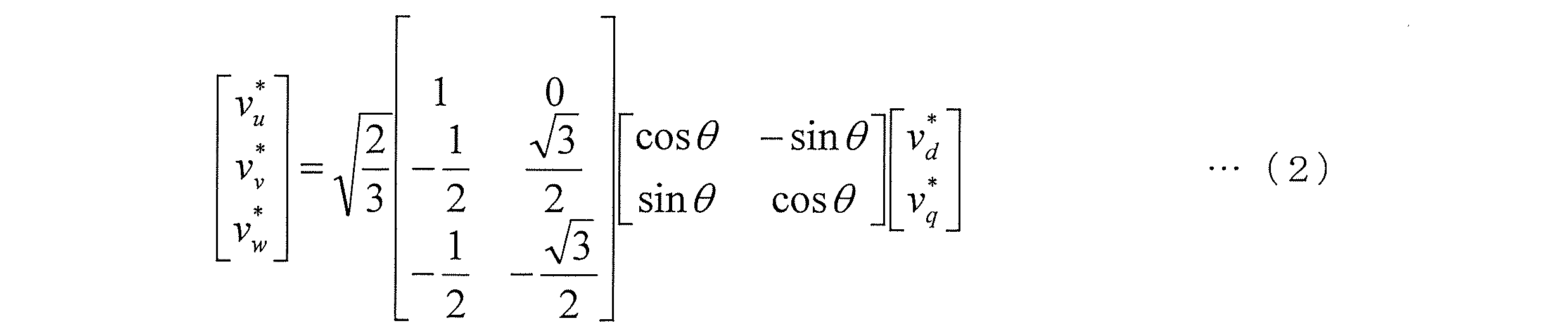
- the two-phase / three-phase conversion unit 203 uses the electrical angle ⁇ of the rotor of the motor 109 detected by the motor angle detection unit 206 to input the input dq axis voltage command value (vd *, vq *) as follows: Based on (2), it is converted into a three-phase voltage command value (vu *, vv *, vw *).
- the 2-phase / 3-phase converter 203 outputs the calculated 3-phase voltage command values (vu *, vv *, vw *) to the switch signal converter 204.
- the switch signal conversion unit 204 Based on the comparison result between the three-phase voltage command values (vu *, vv *, vw *) and the carrier wave (for example, a triangular wave of about several kHz to several tens kHz), the switch signal conversion unit 204 sends the switching element 107 to the inverter 105. A switching signal (PWM signal) for switching the signal is generated. Then, the switch signal conversion unit 204 outputs the switching signal to the inverter 105 to cause the motor 109 to generate a desired torque.
- PWM signal PWM signal
- the switch signal conversion unit 204 of the present embodiment receives the short circuit switching start signal from the short circuit switching control unit 208, the switch signal conversion unit 204 stops the normal switching control based on the switching signal and executes the short circuit switching control.
- a switching signal (on signal) for turning on (closing) the switching element 107 is generated and output to the inverter 105.
- the switch signal conversion unit 204 of the present embodiment receives a short circuit switching stop signal from the short circuit switching control unit 208, the switch signal conversion unit 204 outputs a switching signal (stop signal) to stop the short circuit switching control to the inverter 105. .
- the inverter 105 appropriately executes normal switching control and short-circuit switching control (non-normal switching control) based on the switching signal.
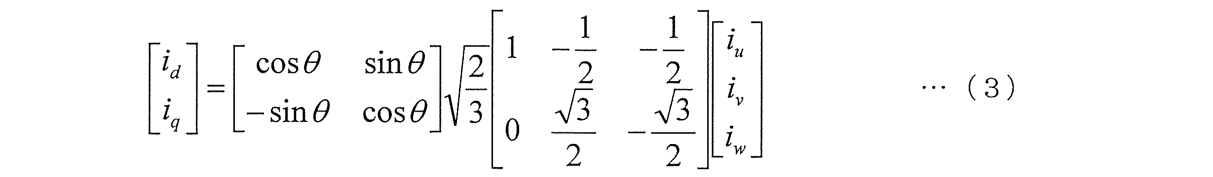
- the three-phase / two-phase conversion unit 205 converts the three-phase actual current values (iu, iv, iw) detected by the current sensor 111 based on the electrical angle ⁇ from the motor angle detection unit 206 to the following formula (3). Based on the motor current value (id, iq).
- the three-phase / two-phase conversion unit 205 outputs the obtained motor current value (id, iq) to the current control unit 202 and the short-circuit switching control unit 208.
- the motor angle detection unit 206 detects the electrical angle ⁇ and the motor electrical angular velocity ⁇ by a rotational position detector 110 such as a resolver provided in the motor 109.
- the motor angle detection unit 206 outputs the detected electrical angle ⁇ to the three-phase / two-phase conversion unit 205, and outputs the detected motor electrical angular velocity ⁇ to the current command value calculation unit 201 and the short-circuit switching control unit 208.
- DC voltage detector 207 detects inverter voltage HV. More specifically, the DC voltage detection unit 207 detects the voltage of the smoothing capacitor 108 of the inverter 105 as the inverter voltage HV. The DC voltage detection unit 207 outputs the detected inverter voltage HV to the current command value calculation unit 201.
- the short-circuit switching control unit 208 determines whether or not to execute the short-circuit switching control based on the relay on / off signal input from the vehicle controller 102. Further, the short-circuit switching control unit 208 determines whether or not to stop the short-circuit switching control according to the state of the motor 109 during the execution of the short-circuit switching control. When it is determined that the short circuit switching control is to be executed, the short circuit switching control unit 208 stops the normal switching control and outputs a short circuit switching start signal for executing the short circuit switching control to the switch signal conversion unit 204. In addition, when it is determined that the short circuit switching control is to be stopped, the short circuit switching control unit 208 outputs a short circuit switching stop signal to the switch signal conversion unit 204. Below, the process by the short circuit switching control part 208 is demonstrated in detail.
- FIG. 2 is a flowchart for explaining the flow of start / stop determination of the short-circuit switching control executed by the short-circuit switching control unit 208. It should be noted that the following control routine is programmed in the controller so as to be repeatedly executed at a predetermined cycle during the startup of the inverter control system.
- step S101 the short circuit switching control unit 208 determines whether or not a relay-off signal output from the vehicle controller 102 when, for example, it is determined that the battery 103 is not normal is received. That is, the short circuit switching control unit 208 determines whether or not the power supply from the battery 103 to the inverter 105 is stopped. When determining that the relay-off signal has been received, the short-circuit switching control unit 208 determines that the power supply from the battery 103 to the inverter 105 has been stopped, and proceeds to the process of step S102.
- the short-circuit switching control unit 208 determines that the relay-off signal has not been received, the short-circuit switching control unit 208 determines that power is being supplied from the battery 103 to the inverter 105, proceeds to step S103, and continues normal switching control. To do.
- step S102 the short circuit switching control unit 208 outputs a switching start signal to the switch signal conversion unit 204 in order to start the short circuit switching control.
- the short-circuit switching control in which the switching elements Supu, Supv, Supw, Sdwu, Sdwv, Sdww of the inverter 105 are all turned on is started.
- the subsequent process of step S104 is executed.
- the short-circuit switching control unit 208 determines whether or not to stop the short-circuit switching control based on a motor state parameter serving as a determination index as to whether or not vibrations occur in the vehicle.
- the motor state parameter of the present embodiment is the rotational speed of the motor 109 (hereinafter referred to as “motor rotational speed”) or an estimated value of the braking torque of the motor 109 (hereinafter referred to as “estimated torque”). That is, the short circuit switching control unit 208 of the present embodiment determines whether or not to stop the short circuit switching control based on the motor rotation speed or the estimated torque.
- step S104 is executed based on the motor rotation speed.
- step S104 the short circuit switching control unit 208 determines whether or not the absolute value of the motor rotational speed (rotational speed) is less than a predetermined rotational speed threshold.
- the motor rotation speed (rpm) as the motor state parameter is obtained by multiplying the motor electrical angular velocity ⁇ (rad / s) output from the motor angle detection unit 206 by 60 / (2 ⁇ ).
- the short circuit switching control unit 208 proceeds to step S105 and stops the short circuit switching control.
- the motor 109 which is a permanent magnet synchronous motor, rotates when the short-circuit switching control is continued.
- a braking torque corresponding to the number is generated.
- This change in braking torque causes torsional vibration of the drive shaft 114.
- the rate of change of the braking torque has a characteristic that increases when the motor speed is low. For this reason, if the braking torque changes greatly in the low rotation region at the time of relay cut, the torsional vibration of the drive shaft 114 is excited.
- step S104 when the absolute value of the motor rotation speed is less than the predetermined rotation speed threshold, it is determined that the short-circuit switching control is stopped. Thereby, generation
- the short circuit switching control unit 208 proceeds to step S106 and continues the short circuit switching control.
- the inverter voltage HV rises to a high voltage due to the generation of the induced voltage due to the stop of the short-circuit switching control.
- a specific method for setting the predetermined rotation speed threshold will be described later.
- step S104 is executed based on the estimated torque.
- step S104 the short circuit switching control unit 208 determines whether or not the absolute value of the estimated torque exceeds a predetermined torque threshold value.
- the braking torque of the motor 109 may be estimated (acquired) by a known method, and the estimation (acquisition) method is not particularly limited.
- the short circuit switching control unit 208 proceeds to step S105 and stops the short circuit switching control. That is, in the process of step S104, braking torque (estimated torque) that is a direct cause of torsional vibration of the drive shaft 114 may be used as a determination index instead of the motor rotation speed. A specific method for setting the predetermined torque threshold will be described later.
- the short circuit switching control unit 208 proceeds to step S106 and continues the short circuit switching control.
- FIG. 3 shows a block configuration including a motor 109 during short-circuit switching control, that is, a three-phase short-circuit, and a vehicle model representing the transmission characteristics of the vehicle on which the motor 109 is mounted.
- the variable gain 301 (gain K) is a gain indicating the characteristics of the motor 109 at the time of a three-phase short circuit.
- the variable gain 301 has characteristics as shown in FIG.
- FIG. 4 is a diagram showing the characteristics of the variable gain 301, that is, the characteristics of the motor 109 when the three-phase is short-circuited.
- the motor 109 at the time of the three-phase short circuit has a characteristic that the torque changes nonlinearly according to the rotational speed.
- the inverter voltage HV of the inverter 105 becomes 0V
- the interphase voltage becomes 0V, so that the motor 109 is in the same state as when the three-phase is short-circuited.
- the characteristics of the motor 109 at the time of the three-phase short circuit are, in other words, the motor 109 when the relay 104 is opened (relay cut), that is, when the power supply from the battery 103 to the inverter 105 is stopped. It can be expressed as a characteristic.
- a vehicle model 302 (Gp (s)) shown in FIG. 3 is a vehicle model obtained by modeling a vehicle driving force transmission system, and shows a transmission characteristic from the vehicle output torque (motor torque Tm) to the motor rotation speed. It is a model.
- the details of the model Gp (s) will be described.
- FIG. 5 is a diagram in which a driving force transmission system of a vehicle is modeled, and each parameter in the figure is as shown below.
- a 4 , a 3 , a 2 , a 1, b 3 , b 2 , b 1 , b 0 in the formula (9) are represented by the following formulas (10) to (17).
- variable gain 301 variable gain K
- vehicle model 302 Gp (s)
- FIG. 6 is a diagram showing a simulation result (time response) using the block configuration shown in FIG.
- the upper part shows the time response of the braking torque (estimated torque), and the lower part shows the time response of the motor speed.
- Dotted lines indicated by A and B in the figure indicate points where the motor rotation speed and the estimated torque start to vibrate in the process in which the motor rotation speed gradually decreases after the three-phase short circuit.
- the “predetermined torque threshold” in the present embodiment is based on A indicating the estimated torque at which the estimated torque starts vibration
- the “predetermined rotational speed threshold” is based on B indicating the motor rotational speed at which the motor rotational speed starts vibration. Is set.
- the torque shown in the upper part of the figure is a braking torque
- at least the torque near the point indicated by A is a negative value in principle. Therefore, the “predetermined torque threshold” is set based on the absolute value of the torque indicated by A.
- the motor 109 which is a permanent magnet synchronous motor continues the short-circuit switching control when the relay 104 is opened and the inverter voltage HV becomes 0 V, the braking torque corresponding to the motor rotational speed is applied. Occur.
- the rate of change of the braking torque has a characteristic that increases when the motor speed is low. For this reason, the torsional vibration of the drive shaft 114 is excited by a large change in the braking torque in the low rotation region at the time of relay cut.
- the “predetermined rotation speed threshold” is set to a value equal to or greater than the absolute value of the rotation speed (see B) at which the motor rotation speed starts to vibrate. Accordingly, when it is determined in step S102 shown in FIG. 2 that the absolute value of the motor rotational speed is less than the predetermined rotational speed threshold value, the short circuit switching control is stopped before the motor rotational speed starts to vibrate. Generation of torsional vibration of the shaft 114 can be avoided.
- the “predetermined torque threshold” is set to a value equal to or less than the absolute value of the torque at which the torque of the motor 109 starts to vibrate. Accordingly, when it is determined in step S102 shown in FIG. 2 that the absolute value of the estimated torque exceeds the predetermined torque threshold, the short-circuit switching control is stopped before the torque of the motor 109 starts to vibrate. Generation of torsional vibration of the shaft 114 can be avoided.
- the short-circuit switching control unit 208 performs short-circuit switching of the inverter 105. In order to stop the control, the process proceeds to step S105.
- step S105 the short circuit switching control unit 208 outputs a short circuit switching stop signal to the switch signal conversion unit 204 in order to release the three-phase short circuit state of the inverter 105. Thereby, the short circuit switching control of the inverter 105 is stopped.
- the switching elements Supu, Supv, Supw, Sdwu, Sdwv, and Sdww included in the inverter 105 are all turned off (opened).
- step S104 when step S104 is NO, the process of step S106 is executed.
- step S ⁇ b> 106 the short circuit switching control unit 208 determines that there is no possibility of the vibration of the drive shaft 114 described above, does not output the switching stop signal, and ends the short circuit switching control start / stop determination process. Thereby, the short circuit switching control of the inverter 105 based on the torque command value T * from the vehicle controller 102 is continued.
- the inverter control method includes a motor 109 that transmits torque to the drive wheels 115, an inverter 105 that converts DC power into AC power and supplies the AC power to the motor 109, and a DC power source that supplies DC power to the inverter 105 ( An inverter control method for controlling switching of the inverter 105 in a vehicle including the battery 103). This inverter control method determines whether or not the power supply to the inverter 105 is stopped, and is a variable that represents the state of the motor 109 and serves as a determination index for whether or not vibrations occur in the vehicle. To get.
- the short-circuit switching control of the inverter 105 is stopped before vibration is generated in the vehicle based on the acquired motor state parameter. Accordingly, since the short-circuit switching control of the inverter 105 can be stopped before the occurrence of the vibration of the vehicle due to the torsional vibration of the drive shaft 114, when the power supply from the battery 103 to the inverter 105 is stopped, Generation of vibration can be avoided.
- the inverter control method of one embodiment stops the short-circuit switching control when the absolute value of the motor rotational speed as the motor state parameter is less than the predetermined rotational speed threshold, and the absolute value of the motor rotational speed is the predetermined rotational speed. If the threshold is greater than or equal to several thresholds, short-circuit switching control is continued. As a result, the short-circuit switching control can be stopped before the occurrence of vibration of the vehicle using the motor rotation speed as a determination index. Further, since the short-circuit switching control is continued when the absolute value of the motor rotational speed is equal to or greater than the predetermined rotational speed threshold, it is possible to avoid the inverter voltage HV from becoming a high voltage due to the induced voltage.
- the predetermined rotation speed threshold is set to a value equal to or larger than the absolute value of the motor rotation speed at the timing when the rotation of the motor rotation speed starts after the power supply to the inverter 105 is stopped. Is done.
- the predetermined rotation speed threshold value to be compared with the motor rotation speed is set to be greater than or equal to the absolute value of the rotation speed at which the vehicle starts to vibrate, so that it is possible to reliably avoid the occurrence of vibration in the vehicle.
- the inverter control method stops the short-circuit switching control when the absolute value of the torque as the motor state parameter exceeds a predetermined torque threshold, and short-circuits when the absolute value of the torque is equal to or less than the predetermined torque threshold. Continue switching control. As a result, the short-circuit switching control of the inverter 105 can be stopped before the occurrence of vehicle vibration, using the estimated torque as a determination index.
- the predetermined torque threshold value is set to a value equal to or less than the absolute value of the torque at the timing when torque vibration starts after the power supply to the inverter 105 is stopped.
- the predetermined torque threshold value to be compared with the estimated torque is set to be equal to or greater than the absolute value of the torque at which the vehicle starts to vibrate, so that it is possible to reliably avoid the occurrence of vibration in the vehicle.
- the short-circuit switching control unit 208 performs short-circuit switching control with the reception of a relay-off signal indicating that the relay 104 is turned off (cut off) as a trigger.
- the short-circuit switching control may be executed with a trigger that the inverter voltage HV exceeds the specification voltage range of the battery 103. That is, as a trigger for executing short-circuit switching control, detection of an arbitrary event indicating that a short-circuit switching control execution request has occurred according to the state of the battery 103 can be employed.
- the inverter control method according to the present invention is not necessarily executed on the basis of the motor control device 100 shown in FIG. 1, and may be executed on the assumption of the motor control device 200 shown in FIG.
- the motor control device 200 detects the motor temperature provided in the motor 109 and the thermistor 112 that detects the motor temperature, and detects the capacitor temperature. And thermistor 113.
- the detected motor temperature and capacitor temperature are output to the short-circuit switching control unit 208. That is, according to the motor control apparatus 200, the short circuit switching control unit 208 can execute the short circuit switching control stop determination in consideration of the detected motor temperature and capacitor temperature. Accordingly, it is possible to execute stop determination with higher accuracy in consideration of the temperature characteristics of at least one of the motor 109 and the inverter 105.
Abstract
This inverter control method controls switching of an inverter in a vehicle provided with: a motor which delivers torques to driving wheels; an inverter which converts DC power into AC power to supply the AC power to the motor; and a DC power supply which supplies DC power to the inverter. The inverter control method includes: determining whether power supplying to the inverter is stopped; executing a short-circuit switching control for putting a switching element included in the inverter in an on-state when the power supplying to the inverter is stopped; and acquiring, as a variable for indicating a state of the motor, a motor state parameter that is a determination index about whether vibration occurs in the vehicle. In addition, when the power supplying to the inverter is stopped, the short-circuit switching control is stopped on the basis of the acquired motor state parameter, before the vibration occurs in the vehicle.
Description
本発明は、インバータ制御方法及びインバータ制御システムに関する。
The present invention relates to an inverter control method and an inverter control system.
JP2006-74841Aには、モータの回転中にモータへの電力供給が停止した場合に、インバータの入力側に接続されたコンデンサ(平滑コンデンサ)の電圧(インバータの直流電圧)が所定値以上になるとモータのコイルを短絡するようにインバータを制御(非通常スイッチング制御)するモータ制御装置が開示されている。
JP 2006-74841A discloses that when the power supply to the motor is stopped during the rotation of the motor, the voltage of the capacitor (smoothing capacitor) connected to the input side of the inverter (DC voltage of the inverter) exceeds a predetermined value. A motor control device that controls an inverter (non-normal switching control) so as to short-circuit the coil is disclosed.
しかしながら、上記モータ制御装置において、モータの回転数が低下してきたときにコイルを短絡するようにインバータを制御すると、モータが発生する制動トルクが大きくなり、車体振動が引き起こされる場合がある。
However, in the above motor control device, when the inverter is controlled so as to short-circuit the coil when the rotational speed of the motor is reduced, the braking torque generated by the motor may increase and cause vehicle body vibration.
本発明は、このような事情に鑑みてなされたものであり、モータが発生する制動トルクが大きくなることに起因する車体振動の発生を回避し得るインバータ制御方法及びインバータ制御システムを提供することを目的とする。
The present invention has been made in view of such circumstances, and provides an inverter control method and an inverter control system capable of avoiding the occurrence of vehicle body vibration caused by an increase in braking torque generated by a motor. Objective.
本発明のある態様によれば、駆動輪にトルクを伝達するモータと、直流電力を交流電力に変換してモータに供給するインバータと、インバータへ直流電力を供給する直流電源と、を備える車両においてインバータのスイッチングを制御するインバータ制御方法であって、インバータへの電力供給が停止されているか否かを判定し、インバータへの電力供給が停止されている場合に、インバータが有するスイッチング素子をオン状態にする短絡スイッチング制御を実行し、モータの状態を表す変数であって車両に振動が発生するか否かの判定指標となるモータ状態パラメータを取得する。そして、インバータへの電力供給が停止されている場合に、取得したモータ状態パラメータに基づいて、車両に振動が発生する以前に短絡スイッチング制御を停止する。
According to an aspect of the present invention, in a vehicle comprising: a motor that transmits torque to drive wheels; an inverter that converts DC power to AC power and supplies the motor; and a DC power source that supplies DC power to the inverter An inverter control method for controlling switching of an inverter, wherein whether or not power supply to the inverter is stopped is determined, and when the power supply to the inverter is stopped, a switching element included in the inverter is turned on The short-circuit switching control is executed to obtain a motor state parameter which is a variable representing the state of the motor and serves as an index for determining whether or not vibrations occur in the vehicle. Then, when the power supply to the inverter is stopped, the short-circuit switching control is stopped before vibration is generated in the vehicle based on the acquired motor state parameter.
(第1実施形態)
以下、図面等を参照して、本発明の一実施形態について説明する。なお、以下の説明においては、記載の簡略化のため、電流及び電圧等の3相成分及びd-q座標成分を、「dq軸電流値(id,iq)」、及び「3相電流値(iu,iv,iw)」等のように必要に応じてまとめて表記する。 (First embodiment)
Hereinafter, an embodiment of the present invention will be described with reference to the drawings. In the following description, for simplification of description, a three-phase component such as current and voltage and a dq coordinate component are expressed as “dq axis current value (id, iq)” and “three-phase current value ( (iu, iv, iw) ”and so on.
図1は、本実施形態のモータ制御装置100の構成を説明する図である。
FIG. 1 is a diagram illustrating the configuration of a motor control device 100 according to the present embodiment.
本実施形態のインバータ制御システムを構成するモータ制御装置100は、電動車両などに搭載されて車両の駆動輪に接続される電動機(永久磁石同期電動機)としてのモータ109の動作をインバータ105を介して制御する装置である。
The motor control device 100 that constitutes the inverter control system of the present embodiment performs the operation of the motor 109 as an electric motor (permanent magnet synchronous motor) mounted on an electric vehicle or the like and connected to a driving wheel of the vehicle via the inverter 105. It is a device to control.
図示のように、モータ制御装置100は、主として、ドライバ操作情報指令部101と、車両コントローラ102と、バッテリ103と、リレー104と、インバータ105と、モータ制御部106と、を有している。
As illustrated, the motor control device 100 mainly includes a driver operation information command unit 101, a vehicle controller 102, a battery 103, a relay 104, an inverter 105, and a motor control unit 106.
ドライバ操作情報指令部101は、EVキー、シフト・ブレーキ、及びアクセルペダルなどにドライバによる操作が行われた場合に、当該操作に基づいた操作検出信号を車両コントローラ102に送信する。
The driver operation information command unit 101 transmits an operation detection signal based on the operation to the vehicle controller 102 when the driver performs an operation on the EV key, the shift / brake, the accelerator pedal, and the like.
車両コントローラ102は、受信した操作検出信号に基づいて、リレー104にオン/オフを指令するオン/オフ指令信号を送信する。また、車両コントローラ102は、上記操作検出信号に応じたトルク指令値T*をモータ制御部106の電流指令値演算部201に出力する。
The vehicle controller 102 transmits an on / off command signal for commanding the relay 104 to turn on / off based on the received operation detection signal. Further, the vehicle controller 102 outputs a torque command value T * corresponding to the operation detection signal to the current command value calculation unit 201 of the motor control unit 106.
さらに、本実施形態の車両コントローラ102は、バッテリ103のSOC(state of charge)などの状態を表すパラメータに基づいて、バッテリ103の充電量が所定の基準値より低下した状態としての電欠状態であるか否かの判断を含むバッテリ103が正常であるか否かを判定するバッテリ診断を実行する。
Further, the vehicle controller 102 according to the present embodiment is in an electric shortage state as a state in which the charge amount of the battery 103 is lower than a predetermined reference value based on a parameter representing a state such as SOC (state of charge) of the battery 103. A battery diagnosis that determines whether or not the battery 103 is normal, including whether or not there is, is executed.
そして、車両コントローラ102は、バッテリ103が正常ではないと判定すると、バッテリ103の充電量の消費を抑制する観点から、トルク指令値T*をゼロに設定して電流指令値演算部201に出力する。さらに、この場合、車両コントローラ102は、リレー104にオフ指令信号を送信する。
If the vehicle controller 102 determines that the battery 103 is not normal, the torque command value T * is set to zero and output to the current command value calculation unit 201 from the viewpoint of suppressing consumption of the charge amount of the battery 103. . Furthermore, in this case, the vehicle controller 102 transmits an off command signal to the relay 104.
バッテリ103は、力行時にインバータ105を介してモータ109に電力を供給する電源として機能する。換言すれば、バッテリ103は、インバータ105に直流電源を供給する直流電源として機能する。また、バッテリ103は、回生時にインバータ105を介してモータ109から供給される電力を蓄電する。
The battery 103 functions as a power source that supplies power to the motor 109 via the inverter 105 during power running. In other words, the battery 103 functions as a DC power supply that supplies DC power to the inverter 105. The battery 103 stores electric power supplied from the motor 109 via the inverter 105 during regeneration.
リレー104は、車両コントローラ102からの上記オン/オフ指令信号に応じて、バッテリ103とインバータ105との間を導通させる状態(オン状態)、及びこれらの間を電気的に遮断する状態(オフ状態)が切り替わるように開閉する。特に、リレー104は、車両コントローラ102からのオフ指令信号を受けると、バッテリ103とインバータ105との間を電気的に遮断するように開放する。
In accordance with the on / off command signal from the vehicle controller 102, the relay 104 is in a state in which the battery 103 and the inverter 105 are electrically connected (on state), and in a state in which they are electrically disconnected (off state). ) To open and close. In particular, when relay 104 receives an off command signal from vehicle controller 102, relay 104 opens so as to electrically disconnect between battery 103 and inverter 105.
インバータ105は、上記トルク指令値T*に基づいて生成されるモータ制御部106からのスイッチング信号に応じて、バッテリ103からの直流電力を3相交流電力に変換してモータ109に供給する。
The inverter 105 converts DC power from the battery 103 into three-phase AC power and supplies it to the motor 109 in accordance with a switching signal from the motor control unit 106 generated based on the torque command value T *.
より具体的に、インバータ105は、直流電力と3相交流電力の間の変換を行うためのスイッチング素子107と、当該インバータ105内部の電圧を平滑化する平滑コンデンサ108と、を有する。
More specifically, the inverter 105 includes a switching element 107 for converting between DC power and three-phase AC power, and a smoothing capacitor 108 that smoothes the voltage inside the inverter 105.
スイッチング素子107は、上アームSupの3相(U相、V相、W相)のスイッチング素子Supu,Supv,Supwと、下アームSdwの3相のスイッチング素子Sdwu,Sdwv,Sdww(U相、V相、W相)とを備える。なお、各スイッチング素子は、例えば、IGBT(Insulated Gate Bipolar Transistor)により構成されるが、他にも、バイポーラトランジスタ、MOSFET、及びGTO(Gate Turn-Off thyristor)などを用いてもよい。また、各スイッチング素子Supu,Supv,Supw,Sdwu,Sdwv,Sdwwには、逆並列にダイオードが接続されている。そして、各スイッチング素子Supu,Supv,Supw,Sdwu,Sdwv,Sdwwは、後述するスイッチ信号変換部204からスイッチング信号としてのPWM(Pulse Wide Modulation)信号を受信すると、当該PWM信号に応じたディーティー比で開閉される。すなわち、スイッチング素子107は、PWM信号に基づいたスイッチング制御(通常スイッチング制御)にしたがって開閉される。
The switching element 107 includes three-phase (U-phase, V-phase, W-phase) switching elements Supu, Supv, Supw of the upper arm Sup and three-phase switching elements Sdwu, Sdwv, Sdww (U-phase, V-phase) of the lower arm Sdw. Phase, W phase). Each switching element is configured by, for example, an IGBT (Insulated Gate Bipolar Transistor), but a bipolar transistor, a MOSFET, a GTO (Gate Turn-Off thyristor), or the like may be used. In addition, a diode is connected in antiparallel to each switching element Supu, Supv, Supw, Sdwu, Sdwv, Sdww. When each switching element Supu, Supv, Supw, Sdwu, Sdwv, Sdww receives a PWM (PulseulWide Modulation) signal as a switching signal from the switch signal conversion unit 204 described later, the duty ratio corresponding to the PWM signal is received. Open and close. That is, the switching element 107 is opened and closed according to switching control (normal switching control) based on the PWM signal.
これにより、モータ109は、トルク指令値T*(>0)に応じたモータ駆動力を発生することとなる。なお、トルク指令値T*が負の場合には、インバータ105は、モータ109の回生電力を直流電力に変換してバッテリ103に充電する。
Thus, the motor 109 generates a motor driving force according to the torque command value T * (> 0). When torque command value T * is negative, inverter 105 converts the regenerative power of motor 109 into DC power and charges battery 103.
また、本実施形態のスイッチング素子107は、後述する短絡スイッチング制御部208からの短絡スイッチング開始信号をスイッチ信号変換部204が受信した場合には、各スイッチング素子Supu,Supv,Supw,Sdwu,Sdwv,Sdwwを全てオン(閉)状態とすることによりインバータ105を三相短絡状態とする短絡スイッチング制御を実行する。またさらに、スイッチング素子107は、短絡スイッチング制御部208からの短絡スイッチング停止信号をスイッチ信号変換部204が受信した場合には、短絡スイッチング制御を停止してインバータ105の三相短絡状態を解除する。短絡スイッチング制御の開始および停止の詳細については後述する。
In addition, when the switch signal conversion unit 204 receives a short circuit switching start signal from a short circuit switching control unit 208 described later, the switching element 107 of the present embodiment has each switching element Supu, Supv, Supw, Sdwu, Sdwv, Short-circuit switching control is performed to place the inverter 105 in a three-phase short-circuit state by setting all Sdww to an on (closed) state. Furthermore, when the switch signal conversion unit 204 receives the short circuit switching stop signal from the short circuit switching control unit 208, the switching element 107 stops the short circuit switching control and releases the three-phase short circuit state of the inverter 105. Details of the start and stop of the short-circuit switching control will be described later.
次に、モータ制御部106は、電流指令値演算部201と、電流制御部202と、2相/3相変換部203と、スイッチ信号変換部204と、3相/2相変換部205と、モータ角検出部206と、直流電圧検出部207と、短絡スイッチング制御部208と、を有している。なお、本実施形態のモータ制御部106の構成は、CPU等の各種演算・制御装置、ROM及びRAM等の各種記憶装置、並びに入出力インターフェース等を備える1又は2以上のコントローラにより実現される。
Next, the motor control unit 106 includes a current command value calculation unit 201, a current control unit 202, a 2-phase / 3-phase conversion unit 203, a switch signal conversion unit 204, a 3-phase / 2-phase conversion unit 205, A motor angle detection unit 206, a DC voltage detection unit 207, and a short circuit switching control unit 208 are included. The configuration of the motor control unit 106 according to the present embodiment is realized by one or more controllers including various arithmetic / control devices such as a CPU, various storage devices such as a ROM and a RAM, and an input / output interface.
電流指令値演算部201は、トルク指令値T*、モータ109の電気角速度(以下では、「モータ電気角速度ω」とも称する)、インバータ105の直流電圧であるインバータ電圧HVに基づいて、d軸電流指令値id*、及びq軸電流指令値iq*を演算する。
The current command value calculation unit 201 uses the d-axis current based on the torque command value T *, the electrical angular velocity of the motor 109 (hereinafter also referred to as “motor electrical angular velocity ω”), and the inverter voltage HV that is the DC voltage of the inverter 105. Command value id * and q-axis current command value iq * are calculated.
より詳細には、電流指令値演算部201は、トルク指令値T*、モータ電気角速度ω、及びインバータ電圧HVの間の関係を定めた所定のテーブルに基づいて、dq軸電流指令値(id*,iq*)を演算する。電流指令値演算部201は、演算したdq軸電流指令値(id*,iq*)を電流制御部202に出力する。
More specifically, the current command value calculation unit 201 determines the dq-axis current command value (id *) based on a predetermined table that defines the relationship between the torque command value T *, the motor electrical angular velocity ω, and the inverter voltage HV. , Iq *). The current command value calculation unit 201 outputs the calculated dq axis current command value (id *, iq *) to the current control unit 202.
電流制御部202は、モータ109に実際に流れるdq軸電流値(id,iq)が、電流指令値演算部201から入力されるdq軸電流指令値(id*,iq*)に近づくように、dq軸電圧指令値(vd*,vq*)を演算する。なお、以下では、モータ109に実際に流れるdq軸電流値を、「モータ電流値(id,iq)」又は「モータ電流値i」とも称する。
The current control unit 202 is configured so that the dq axis current value (id, iq) actually flowing to the motor 109 approaches the dq axis current command value (id *, iq *) input from the current command value calculation unit 201. Calculates the dq axis voltage command value (vd *, vq *). Hereinafter, the dq-axis current value that actually flows through the motor 109 is also referred to as “motor current value (id, iq)” or “motor current value i”.
例えば、電流制御部202は、以下の式(1)に従うPI制御に基づいて、dq軸電圧指令値(vd*,vq*)を演算する。
For example, the current control unit 202 calculates the dq axis voltage command value (vd *, vq *) based on the PI control according to the following equation (1).

なお、式(1)中のKpd及びKpqはそれぞれd軸比例ゲイン及びq軸比例ゲインを意味する。また、Kid及びKiqはそれぞれd軸積分ゲイン及びq軸積分ゲインを意味する。さらに、Ld及びLqはそれぞれd軸インダクタンス及びq軸インダクタンスを意味する。また、φは永久磁石鎖交磁束数を意味する。
In the equation (1), Kpd and Kpq mean d-axis proportional gain and q-axis proportional gain, respectively. Kid and Kiq mean a d-axis integral gain and a q-axis integral gain, respectively. Further, Ld and Lq mean d-axis inductance and q-axis inductance, respectively. Further, φ means the number of permanent magnet linkage magnetic fluxes.
そして、電流制御部202は、演算したdq軸電圧指令値(vd*,vq*)を2相/3相変換部203に出力する。
Then, the current control unit 202 outputs the calculated dq-axis voltage command value (vd *, vq *) to the 2-phase / 3-phase conversion unit 203.
2相/3相変換部203は、モータ角検出部206で検出したモータ109の回転子の電気角θを用いて、入力されたdq軸電圧指令値(vd*,vq*)を以下の式(2)に基づいて3相電圧指令値(vu*,vv*,vw*)に変換する。
The two-phase / three-phase conversion unit 203 uses the electrical angle θ of the rotor of the motor 109 detected by the motor angle detection unit 206 to input the input dq axis voltage command value (vd *, vq *) as follows: Based on (2), it is converted into a three-phase voltage command value (vu *, vv *, vw *).
そして、2相/3相変換部203は、演算した3相電圧指令値(vu*,vv*,vw*)をスイッチ信号変換部204に出力する。
The 2-phase / 3-phase converter 203 outputs the calculated 3-phase voltage command values (vu *, vv *, vw *) to the switch signal converter 204.
スイッチ信号変換部204は、3相電圧指令値(vu*,vv*,vw*)と搬送波(例えば数kHz~10数kHz程度の三角波)との比較結果に基づいて、インバータ105にスイッチング素子107をスイッチングするためのスイッチング信号(PWM信号)を生成する。そして、スイッチ信号変換部204は、このスイッチング信号をインバータ105に出力することによりモータ109に所望のトルクを発生させる。
Based on the comparison result between the three-phase voltage command values (vu *, vv *, vw *) and the carrier wave (for example, a triangular wave of about several kHz to several tens kHz), the switch signal conversion unit 204 sends the switching element 107 to the inverter 105. A switching signal (PWM signal) for switching the signal is generated. Then, the switch signal conversion unit 204 outputs the switching signal to the inverter 105 to cause the motor 109 to generate a desired torque.
さらに、本実施形態のスイッチ信号変換部204は、短絡スイッチング制御部208から短絡スイッチング開始信号を受信した場合には、スイッチング信号に基づく通常スイッチング制御を停止して、短絡スイッチング制御を実行するためにスイッチング素子107をオン(閉)状態にするためのスイッチング信号(オン信号)を生成し、インバータ105に出力する。また、本実施形態のスイッチ信号変換部204は、短絡スイッチング制御部208から短絡スイッチング停止信号を受信した場合には、短絡スイッチング制御の停止を指令するスイッチング信号(停止信号)をインバータ105に出力する。
Furthermore, when the switch signal conversion unit 204 of the present embodiment receives the short circuit switching start signal from the short circuit switching control unit 208, the switch signal conversion unit 204 stops the normal switching control based on the switching signal and executes the short circuit switching control. A switching signal (on signal) for turning on (closing) the switching element 107 is generated and output to the inverter 105. In addition, when the switch signal conversion unit 204 of the present embodiment receives a short circuit switching stop signal from the short circuit switching control unit 208, the switch signal conversion unit 204 outputs a switching signal (stop signal) to stop the short circuit switching control to the inverter 105. .
これにより、インバータ105は、上記スイッチング信号に基づいて、通常スイッチング制御と短絡スイッチング制御(非通常スイッチング制御)とを適宜実行する。
Thereby, the inverter 105 appropriately executes normal switching control and short-circuit switching control (non-normal switching control) based on the switching signal.
3相/2相変換部205は、モータ角検出部206からの電気角θに基づいて、電流センサ111で検出された3相実電流値(iu,iv,iw)を以下の式(3)に基づいてモータ電流値(id,iq)に変換する。
The three-phase / two-phase conversion unit 205 converts the three-phase actual current values (iu, iv, iw) detected by the current sensor 111 based on the electrical angle θ from the motor angle detection unit 206 to the following formula (3). Based on the motor current value (id, iq).
3相/2相変換部205は、得られたモータ電流値(id,iq)を電流制御部202及び短絡スイッチング制御部208に出力する。
The three-phase / two-phase conversion unit 205 outputs the obtained motor current value (id, iq) to the current control unit 202 and the short-circuit switching control unit 208.
モータ角検出部206は、モータ109に設けたレゾルバ等の回転位置検出器110により、電気角θ、及びモータ電気角速度ωを検出する。モータ角検出部206は、検出した電気角θを3相/2相変換部205に出力するとともに、検出したモータ電気角速度ωを電流指令値演算部201及び短絡スイッチング制御部208に出力する。
The motor angle detection unit 206 detects the electrical angle θ and the motor electrical angular velocity ω by a rotational position detector 110 such as a resolver provided in the motor 109. The motor angle detection unit 206 outputs the detected electrical angle θ to the three-phase / two-phase conversion unit 205, and outputs the detected motor electrical angular velocity ω to the current command value calculation unit 201 and the short-circuit switching control unit 208.
直流電圧検出部207は、インバータ電圧HVを検出する。より詳細には、直流電圧検出部207は、インバータ105の平滑コンデンサ108の電圧をインバータ電圧HVとして検出する。直流電圧検出部207は、検出したインバータ電圧HVを電流指令値演算部201に出力する。
DC voltage detector 207 detects inverter voltage HV. More specifically, the DC voltage detection unit 207 detects the voltage of the smoothing capacitor 108 of the inverter 105 as the inverter voltage HV. The DC voltage detection unit 207 outputs the detected inverter voltage HV to the current command value calculation unit 201.
短絡スイッチング制御部208は、車両コントローラ102から入力されるリレーオン/オフ信号に基づいて、短絡スイッチング制御を実行するか否かの判定を行う。また、短絡スイッチング制御部208は、短絡スイッチング制御の実行中に、モータ109の状態に応じて短絡スイッチング制御を停止するか否かの判定を行う。短絡スイッチング制御部208は、短絡スイッチング制御を実行すると判定した場合には、通常スイッチング制御を停止するとともに短絡スイッチング制御を実行する短絡スイッチング開始信号をスイッチ信号変換部204に出力する。また、短絡スイッチング制御部208は、短絡スイッチング制御を停止すると判定した場合には、短絡スイッチング停止信号をスイッチ信号変換部204に出力する。以下では、短絡スイッチング制御部208による処理について詳細に説明する。
The short-circuit switching control unit 208 determines whether or not to execute the short-circuit switching control based on the relay on / off signal input from the vehicle controller 102. Further, the short-circuit switching control unit 208 determines whether or not to stop the short-circuit switching control according to the state of the motor 109 during the execution of the short-circuit switching control. When it is determined that the short circuit switching control is to be executed, the short circuit switching control unit 208 stops the normal switching control and outputs a short circuit switching start signal for executing the short circuit switching control to the switch signal conversion unit 204. In addition, when it is determined that the short circuit switching control is to be stopped, the short circuit switching control unit 208 outputs a short circuit switching stop signal to the switch signal conversion unit 204. Below, the process by the short circuit switching control part 208 is demonstrated in detail.
図2は、短絡スイッチング制御部208により実行される短絡スイッチング制御の開始/停止判定の流れを説明するフローチャートである。なお、以下の制御ルーチンは、インバータ制御システムの起動中に所定周期で繰り返し実行されるように上記コントローラにプログラムされている。
FIG. 2 is a flowchart for explaining the flow of start / stop determination of the short-circuit switching control executed by the short-circuit switching control unit 208. It should be noted that the following control routine is programmed in the controller so as to be repeatedly executed at a predetermined cycle during the startup of the inverter control system.
ステップS101において、短絡スイッチング制御部208は、車両コントローラ102から例えばバッテリ103が正常ではないと判定された場合に出力されるリレーオフ信号を受信したか否かを判定する。すなわち、短絡スイッチング制御部208は、バッテリ103からインバータ105への電力供給が停止されたか否かを判定する。短絡スイッチング制御部208は、リレーオフ信号を受信したと判定すると、バッテリ103からインバータ105への電力供給が停止されたと判断して、ステップS102の処理へ移行する。一方、短絡スイッチング制御部208は、リレーオフ信号を受信していないと判定すると、バッテリ103からインバータ105への電力供給は行われていると判断して、ステップS103へ移行し、通常スイッチング制御を継続する。
In step S101, the short circuit switching control unit 208 determines whether or not a relay-off signal output from the vehicle controller 102 when, for example, it is determined that the battery 103 is not normal is received. That is, the short circuit switching control unit 208 determines whether or not the power supply from the battery 103 to the inverter 105 is stopped. When determining that the relay-off signal has been received, the short-circuit switching control unit 208 determines that the power supply from the battery 103 to the inverter 105 has been stopped, and proceeds to the process of step S102. On the other hand, if the short-circuit switching control unit 208 determines that the relay-off signal has not been received, the short-circuit switching control unit 208 determines that power is being supplied from the battery 103 to the inverter 105, proceeds to step S103, and continues normal switching control. To do.
ステップS102において、短絡スイッチング制御部208は、短絡スイッチング制御を開始するためにスイッチ信号変換部204にスイッチング開始信号を出力する。これにより、インバータ105が有するスイッチング素子Supu,Supv,Supw,Sdwu,Sdwv,Sdwwが全てオン状態となる短絡スイッチング制御が開始される。短絡スイッチング制御が開始され、インバータ105が三相短絡状態になると、続くステップS104の処理が実行される。
In step S102, the short circuit switching control unit 208 outputs a switching start signal to the switch signal conversion unit 204 in order to start the short circuit switching control. As a result, the short-circuit switching control in which the switching elements Supu, Supv, Supw, Sdwu, Sdwv, Sdww of the inverter 105 are all turned on is started. When the short-circuit switching control is started and the inverter 105 is in a three-phase short-circuit state, the subsequent process of step S104 is executed.
ステップS104において、短絡スイッチング制御部208は、車両に振動が発生するか否かの判定指標となるモータ状態パラメータに基づいて、短絡スイッチング制御を停止するか否かを判定する。本実施形態のモータ状態パラメータは、モータ109の回転数(以下、モータ回転数)、又は、モータ109の制動トルクの推定値(以下、推定トルク)である。すなわち、本実施形態の短絡スイッチング制御部208は、モータ回転数、又は、推定トルクに基づいて短絡スイッチング制御を停止するか否かを判定する。
In step S104, the short-circuit switching control unit 208 determines whether or not to stop the short-circuit switching control based on a motor state parameter serving as a determination index as to whether or not vibrations occur in the vehicle. The motor state parameter of the present embodiment is the rotational speed of the motor 109 (hereinafter referred to as “motor rotational speed”) or an estimated value of the braking torque of the motor 109 (hereinafter referred to as “estimated torque”). That is, the short circuit switching control unit 208 of the present embodiment determines whether or not to stop the short circuit switching control based on the motor rotation speed or the estimated torque.
まず、ステップS104の処理がモータ回転数に基づいて実行される場合の詳細について説明する。
First, details of the case where the process of step S104 is executed based on the motor rotation speed will be described.
この場合のステップS104では、短絡スイッチング制御部208は、モータ回転数(回転速度)の絶対値が所定の回転数閾値未満か否かを判定する。なお、モータ状態パラメータとしてのモータ回転数(rpm)はモータ角検出部206から出力されるモータ電気角速度ω(rad/s)に60/(2π)を乗算することによって取得される。
In step S104 in this case, the short circuit switching control unit 208 determines whether or not the absolute value of the motor rotational speed (rotational speed) is less than a predetermined rotational speed threshold. The motor rotation speed (rpm) as the motor state parameter is obtained by multiplying the motor electrical angular velocity ω (rad / s) output from the motor angle detection unit 206 by 60 / (2π).
モータ回転数の絶対値が所定の回転数閾値未満の場合は、短絡スイッチング制御部208は、ステップS105に移行し、短絡スイッチング制御を停止する。
When the absolute value of the motor rotational speed is less than the predetermined rotational speed threshold, the short circuit switching control unit 208 proceeds to step S105 and stops the short circuit switching control.
ここで、永久磁石同期電動機であるモータ109は、リレー104が開放(リレーカット)されインバータ105に供給される電圧(インバータ電圧HV)が0Vになった場合に短絡スイッチング制御を継続すると、モータ回転数に応じた制動トルクを発生する。この制動トルクの変化はドライブシャフト114のねじり振動の原因となる。そして、制動トルクの変化率は、モータ回転数が低回転時に大きくなる特性を持つ。このため、リレーカット時の低回転領域において制動トルクが大きく変化すると、ドライブシャフト114のねじり振動を励起してしまう。
Here, when the relay 109 is opened (relay cut) and the voltage supplied to the inverter 105 (inverter voltage HV) is 0 V, the motor 109, which is a permanent magnet synchronous motor, rotates when the short-circuit switching control is continued. A braking torque corresponding to the number is generated. This change in braking torque causes torsional vibration of the drive shaft 114. The rate of change of the braking torque has a characteristic that increases when the motor speed is low. For this reason, if the braking torque changes greatly in the low rotation region at the time of relay cut, the torsional vibration of the drive shaft 114 is excited.
従って、ステップS104では、モータ回転数の絶対値が所定の回転数閾値未満の場合は短絡スイッチング制御を停止すると判定する。これにより、低回転領域において制動トルクが変化することに起因する上記のドライブシャフト114のねじり振動の発生を抑制することができる。
Therefore, in step S104, when the absolute value of the motor rotation speed is less than the predetermined rotation speed threshold, it is determined that the short-circuit switching control is stopped. Thereby, generation | occurrence | production of said torsional vibration of the drive shaft 114 resulting from a braking torque changing in a low rotation area | region can be suppressed.
一方、モータ回転数の絶対値が所定の回転数閾値以上の場合は、短絡スイッチング制御部208は、ステップS106に移行して短絡スイッチング制御を継続する。これにより、短絡スイッチング制御の停止によって誘起電圧が発生することによりインバータ電圧HVが上昇して高電圧となるリスクを回避することができる。なお、所定の回転数閾値の具体的な設定方法については後述する。
On the other hand, when the absolute value of the motor rotational speed is equal to or greater than the predetermined rotational speed threshold, the short circuit switching control unit 208 proceeds to step S106 and continues the short circuit switching control. As a result, it is possible to avoid the risk that the inverter voltage HV rises to a high voltage due to the generation of the induced voltage due to the stop of the short-circuit switching control. A specific method for setting the predetermined rotation speed threshold will be described later.
次に、ステップS104の処理が推定トルクに基づいて実行される場合の詳細について説明する。
Next, details of the case where the process of step S104 is executed based on the estimated torque will be described.
この場合のステップS104では、短絡スイッチング制御部208は、推定トルクの絶対値が所定のトルク閾値を超えるか否かを判定する。なお、モータ109の制動トルクは、公知の方法で推定(取得)すればよく、推定(取得)方法は特に限定されない。
In step S104 in this case, the short circuit switching control unit 208 determines whether or not the absolute value of the estimated torque exceeds a predetermined torque threshold value. The braking torque of the motor 109 may be estimated (acquired) by a known method, and the estimation (acquisition) method is not particularly limited.
推定トルクの絶対値が所定のトルク閾値を超える場合は、上述のモータ回転数の絶対値が所定の回転数閾値未満の場合と同様に、当該トルクの変化がドライブシャフト114のねじり振動を励起してしまう。従って、推定トルクの絶対値が所定のトルク閾値を超える場合は、短絡スイッチング制御部208は、ステップS105に移行し、短絡スイッチング制御を停止する。すなわち、ステップS104の処理は、上述のモータ回転数に代えて、ドライブシャフト114のねじり振動の直接的な原因である制動トルク(推定トルク)を判定指標として用いてもよい。なお、所定のトルク閾値の具体的な設定方法については後述する。
When the absolute value of the estimated torque exceeds the predetermined torque threshold, the change in the torque excites the torsional vibration of the drive shaft 114 as in the case where the absolute value of the motor rotational speed is less than the predetermined rotational speed threshold. End up. Therefore, when the absolute value of the estimated torque exceeds the predetermined torque threshold, the short circuit switching control unit 208 proceeds to step S105 and stops the short circuit switching control. That is, in the process of step S104, braking torque (estimated torque) that is a direct cause of torsional vibration of the drive shaft 114 may be used as a determination index instead of the motor rotation speed. A specific method for setting the predetermined torque threshold will be described later.
一方、推定トルクの絶対値が所定のトルク閾値以下の場合は、短絡スイッチング制御部208は、ステップS106に移行し、短絡スイッチング制御を継続する。
On the other hand, if the absolute value of the estimated torque is less than or equal to the predetermined torque threshold, the short circuit switching control unit 208 proceeds to step S106 and continues the short circuit switching control.
次に、上述の「所定の回転数閾値」および「所定のトルク閾値」の設定方法について説明する。
Next, a method for setting the above-mentioned “predetermined rotation speed threshold” and “predetermined torque threshold” will be described.
図3は、短絡スイッチング制御中、すなわち三相短絡時のモータ109と、モータ109が搭載される車両の伝達特性を表した車両モデルからなるブロック構成を示す。可変ゲイン301(ゲインK)は、三相短絡時のモータ109の特性を示すゲインである。可変ゲイン301は、図4で示すような特性を有している。
FIG. 3 shows a block configuration including a motor 109 during short-circuit switching control, that is, a three-phase short-circuit, and a vehicle model representing the transmission characteristics of the vehicle on which the motor 109 is mounted. The variable gain 301 (gain K) is a gain indicating the characteristics of the motor 109 at the time of a three-phase short circuit. The variable gain 301 has characteristics as shown in FIG.
図4は、可変ゲイン301の特性、即ち、三相短絡時のモータ109の特性を示す図である。図示のとおり、三相短絡時のモータ109は回転数に応じてトルクが非線形に変化する特性を有している。なお、インバータ105のインバータ電圧HVが0Vになると、相間電圧が0Vになるためモータ109は三相短絡時と同じ状態となる。従って、三相短絡時のモータ109の特性とは、換言すると、リレー104が開放(リレーカット)された場合、すなわち、バッテリ103からインバータ105への電力供給が停止されている場合のモータ109の特性と言い表すことができる。
FIG. 4 is a diagram showing the characteristics of the variable gain 301, that is, the characteristics of the motor 109 when the three-phase is short-circuited. As shown in the figure, the motor 109 at the time of the three-phase short circuit has a characteristic that the torque changes nonlinearly according to the rotational speed. When the inverter voltage HV of the inverter 105 becomes 0V, the interphase voltage becomes 0V, so that the motor 109 is in the same state as when the three-phase is short-circuited. Therefore, the characteristics of the motor 109 at the time of the three-phase short circuit are, in other words, the motor 109 when the relay 104 is opened (relay cut), that is, when the power supply from the battery 103 to the inverter 105 is stopped. It can be expressed as a characteristic.
図3で示す車両モデル302(Gp(s))は、車両の駆動力伝達系をモデル化した車両モデルであって、車両の出力トルク(モータトルクTm)からモータ回転数までの伝達特性を示すモデルである。以下、モデルGp(s)の詳細について説明する。
A vehicle model 302 (Gp (s)) shown in FIG. 3 is a vehicle model obtained by modeling a vehicle driving force transmission system, and shows a transmission characteristic from the vehicle output torque (motor torque Tm) to the motor rotation speed. It is a model. Hereinafter, the details of the model Gp (s) will be described.
図5は、車両の駆動力伝達系をモデル化した図であり、同図における各パラメータは、以下に示すとおりである。
FIG. 5 is a diagram in which a driving force transmission system of a vehicle is modeled, and each parameter in the figure is as shown below.
Jm:モータのイナーシャ
Jw:駆動輪のイナーシャ
M:車両の重量
KD:駆動系のねじり剛性
KT:タイヤと路面の摩擦に関する係数
N:オーバーオールギヤ比
r:タイヤの荷重半径
ωm:モータの角速度(モータ回転数)
Tm:モータのトルク
TD:駆動輪のトルク
F:車両に加えられる力
v:車両の速度
ωw:駆動輪の角速度
そして、図11より、以下の運動方程式を導くことができる。 J m: motor inertia J w: inertia of the driving wheels M: weight K D of the vehicle: driving system of the torsional stiffness K T: coefficient relating to friction of the tire and the road surface N: overall gear ratio r: radius load tire omega m: Motor angular speed (motor speed)
T m : Torque of the motor T D : Torque of the driving wheel F: Force applied to the vehicle v: Vehicle speed ω w : Angular speed of the driving wheel From FIG. 11, the following equation of motion can be derived.

式(4)~(8)で示す運動方程式に基づいて、モータトルクTmからモータ回転数までの伝達特性Gp(s)を求めると、次式(9)で表される。
When the transfer characteristic Gp (s) from the motor torque Tm to the motor rotation speed is obtained based on the equation of motion shown in the equations (4) to (8), it is expressed by the following equation (9).

ただし、式(9)中のa4、a3、a2、a1、b3、b2、b1、b0は、次式(10)~(17)で表される。
However, a 4 , a 3 , a 2 , a 1, b 3 , b 2 , b 1 , b 0 in the formula (9) are represented by the following formulas (10) to (17).
式(9)に示す伝達関数の極と零点を調べると、次式(18)で示す伝達関数に近似することができ、1つの極と1つの零点は極めて近い値を示す。これは、次式(18)のαとβが極めて近い値を示すことに相当する。
When the poles and zeros of the transfer function shown in equation (9) are examined, it can be approximated to the transfer function shown in the following equation (18), and one pole and one zero show extremely close values. This corresponds to the fact that α and β in the following equation (18) show extremely close values.

従って、式(18)における極零相殺(α=βと近似する)を行うことにより、次式(19)に示すように、Gp(s)は、(2次)/(3次)の伝達特性を構成する。
Therefore, by performing pole-zero cancellation (approximate α = β) in equation (18), Gp (s) is transmitted as (second order) / (third order) as shown in the following equation (19). Configure characteristics.

以上、図3で示す可変ゲイン301(可変ゲインK)と車両モデル302(Gp(s))の詳細を説明した。次に、図3で示すブロック構成を用いたシミュレーション結果(時間応答)について説明する。
The details of the variable gain 301 (variable gain K) and the vehicle model 302 (Gp (s)) shown in FIG. 3 have been described above. Next, a simulation result (time response) using the block configuration shown in FIG. 3 will be described.
図6は、図3で示すブロック構成を用いたシミュレーション結果(時間応答)を示す図である。上段は制動トルク(推定トルク)の時間応答を示し、下段はモータ回転数の時間応答を示している。図中のA、Bで示す点線は、三相短絡後にモータ回転数が徐々に低下していく過程において、モータ回転数と推定トルクとが振動を開始するポイントを示している。
FIG. 6 is a diagram showing a simulation result (time response) using the block configuration shown in FIG. The upper part shows the time response of the braking torque (estimated torque), and the lower part shows the time response of the motor speed. Dotted lines indicated by A and B in the figure indicate points where the motor rotation speed and the estimated torque start to vibrate in the process in which the motor rotation speed gradually decreases after the three-phase short circuit.
すなわち、本実施形態の「所定のトルク閾値」は推定トルクが振動を開始する推定トルクを示すA、「所定の回転数閾値」はモータ回転数が振動を開始するモータ回転数を示すBに基づいて設定される。ただし、図上段で示すトルクは制動トルクであるため、少なくともAで示すポイント付近のトルクは原則負の値である。従って、「所定のトルク閾値」はAで示すトルクの絶対値に基づいて設定される。
That is, the “predetermined torque threshold” in the present embodiment is based on A indicating the estimated torque at which the estimated torque starts vibration, and the “predetermined rotational speed threshold” is based on B indicating the motor rotational speed at which the motor rotational speed starts vibration. Is set. However, since the torque shown in the upper part of the figure is a braking torque, at least the torque near the point indicated by A is a negative value in principle. Therefore, the “predetermined torque threshold” is set based on the absolute value of the torque indicated by A.
ここで、上述したように、永久磁石同期電動機であるモータ109は、リレー104が開放され、インバータ電圧HVが0Vになった場合に短絡スイッチング制御を継続すると、モータ回転数に応じた制動トルクを発生する。この制動トルクの変化率は、モータ回転数が低回転時に大きくなる特性を持つ。このため、リレーカット時の低回転領域において制動トルクが大きく変化することによってドライブシャフト114のねじり振動を励起してしまう。
Here, as described above, when the motor 109 which is a permanent magnet synchronous motor continues the short-circuit switching control when the relay 104 is opened and the inverter voltage HV becomes 0 V, the braking torque corresponding to the motor rotational speed is applied. Occur. The rate of change of the braking torque has a characteristic that increases when the motor speed is low. For this reason, the torsional vibration of the drive shaft 114 is excited by a large change in the braking torque in the low rotation region at the time of relay cut.
本実施形態では、「所定の回転数閾値」をモータ回転数が振動を開始する回転数(B参照)の絶対値以上の値に設定する。これにより、図2で示すステップS102においてモータ回転数の絶対値が所定の回転数閾値未満と判定された場合に、モータ回転数が振動を開始する前に短絡スイッチング制御が停止されるので、ドライブシャフト114のねじり振動の発生を回避することができる。
In this embodiment, the “predetermined rotation speed threshold” is set to a value equal to or greater than the absolute value of the rotation speed (see B) at which the motor rotation speed starts to vibrate. Accordingly, when it is determined in step S102 shown in FIG. 2 that the absolute value of the motor rotational speed is less than the predetermined rotational speed threshold value, the short circuit switching control is stopped before the motor rotational speed starts to vibrate. Generation of torsional vibration of the shaft 114 can be avoided.
また、本実施形態では、「所定のトルク閾値」をモータ109のトルクが振動を開始するトルクの絶対値以下の値に設定する。これにより、図2で示すステップS102において推定トルクの絶対値が所定のトルク閾値を超えると判定された場合に、モータ109のトルクが振動を開始する前に短絡スイッチング制御が停止されるので、ドライブシャフト114のねじり振動の発生を回避することができる。
In this embodiment, the “predetermined torque threshold” is set to a value equal to or less than the absolute value of the torque at which the torque of the motor 109 starts to vibrate. Accordingly, when it is determined in step S102 shown in FIG. 2 that the absolute value of the estimated torque exceeds the predetermined torque threshold, the short-circuit switching control is stopped before the torque of the motor 109 starts to vibrate. Generation of torsional vibration of the shaft 114 can be avoided.
以上が本実施形態の「所定の回転数閾値」および「所定のトルク閾値」の設定方法の詳細である。以下、図2のフローチャートに戻って説明を続ける。
The above is the details of the setting method of the “predetermined rotation speed threshold” and the “predetermined torque threshold” of the present embodiment. Hereinafter, the description will be continued by returning to the flowchart of FIG.
上述のとおり、モータ回転数が所定の回転数閾値未満と判定された場合、又は、推定トルクが所定のトルク閾値を超えると判定された場合は、短絡スイッチング制御部208は、インバータ105の短絡スイッチング制御を停止するためにステップS105の処理に移行する。
As described above, when it is determined that the motor rotational speed is less than the predetermined rotational speed threshold, or when it is determined that the estimated torque exceeds the predetermined torque threshold, the short-circuit switching control unit 208 performs short-circuit switching of the inverter 105. In order to stop the control, the process proceeds to step S105.
ステップS105では、短絡スイッチング制御部208は、インバータ105の三相短絡状態を解除するためにスイッチ信号変換部204に短絡スイッチング停止信号を出力する。これにより、インバータ105の短絡スイッチング制御が停止される。なお、短絡スイッチング制御が停止されると、例えばインバータ105が有するスイッチング素子Supu,Supv,Supw,Sdwu,Sdwv,Sdwwは全てオフ(開)状態となる。
In step S105, the short circuit switching control unit 208 outputs a short circuit switching stop signal to the switch signal conversion unit 204 in order to release the three-phase short circuit state of the inverter 105. Thereby, the short circuit switching control of the inverter 105 is stopped. When the short circuit switching control is stopped, for example, the switching elements Supu, Supv, Supw, Sdwu, Sdwv, and Sdww included in the inverter 105 are all turned off (opened).
一方、ステップS104がNO判定の場合は、ステップS106の処理が実行される。
On the other hand, when step S104 is NO, the process of step S106 is executed.
ステップS106では、短絡スイッチング制御部208は、上述したドライブシャフト114の振動が発生する虞はないと判断して、スイッチング停止信号を出力せず、短絡スイッチング制御の開始/停止判定処理を終了する。これにより、車両コントローラ102からのトルク指令値T*に基づくインバータ105の短絡スイッチング制御は継続される。
In step S <b> 106, the short circuit switching control unit 208 determines that there is no possibility of the vibration of the drive shaft 114 described above, does not output the switching stop signal, and ends the short circuit switching control start / stop determination process. Thereby, the short circuit switching control of the inverter 105 based on the torque command value T * from the vehicle controller 102 is continued.
以上説明した一実施形態に係るインバータ制御方法によれば、以下の作用効果を奏する。
According to the inverter control method according to the embodiment described above, the following operational effects are obtained.
一実施形態のインバータ制御方法は、駆動輪115にトルクを伝達するモータ109と、直流電力を交流電力に変換してモータ109に供給するインバータ105と、インバータ105へ直流電力を供給する直流電源(バッテリ103)と、を備える車両においてインバータ105のスイッチングを制御するインバータ制御方法である。このインバータ制御方法は、インバータ105への電力供給が停止されているか否かを判定し、モータ109の状態を表す変数であって車両に振動が発生するか否かの判定指標となるモータ状態パラメータを取得する。そして、インバータ105への電力供給が停止されている場合に、取得したモータ状態パラメータに基づいて、車両に振動が発生する以前にインバータ105の短絡スイッチング制御を停止する。これにより、ドライブシャフト114のねじり振動に起因する車両の振動発生以前にインバータ105の短絡スイッチング制御を停止することができるので、バッテリ103からインバータ105への電力供給が停止している際に車両に振動が発生することを回避することができる。
The inverter control method according to an embodiment includes a motor 109 that transmits torque to the drive wheels 115, an inverter 105 that converts DC power into AC power and supplies the AC power to the motor 109, and a DC power source that supplies DC power to the inverter 105 ( An inverter control method for controlling switching of the inverter 105 in a vehicle including the battery 103). This inverter control method determines whether or not the power supply to the inverter 105 is stopped, and is a variable that represents the state of the motor 109 and serves as a determination index for whether or not vibrations occur in the vehicle. To get. Then, when the power supply to the inverter 105 is stopped, the short-circuit switching control of the inverter 105 is stopped before vibration is generated in the vehicle based on the acquired motor state parameter. Accordingly, since the short-circuit switching control of the inverter 105 can be stopped before the occurrence of the vibration of the vehicle due to the torsional vibration of the drive shaft 114, when the power supply from the battery 103 to the inverter 105 is stopped, Generation of vibration can be avoided.
また、一実施形態のインバータ制御方法は、モータ状態パラメータとしてのモータ回転数の絶対値が所定の回転数閾値未満の場合はの短絡スイッチング制御を停止し、モータ回転数の絶対値が所定の回転数閾値以上の場合は短絡スイッチング制御を継続する。これにより、モータ回転数を判定指標として、車両の振動発生以前に短絡スイッチング制御を停止することができる。また、モータ回転数の絶対値が所定の回転数閾値以上の場合には短絡スイッチング制御を継続するので、誘起電圧によりインバータ電圧HVが高電圧になることを回避することができる。
Further, the inverter control method of one embodiment stops the short-circuit switching control when the absolute value of the motor rotational speed as the motor state parameter is less than the predetermined rotational speed threshold, and the absolute value of the motor rotational speed is the predetermined rotational speed. If the threshold is greater than or equal to several thresholds, short-circuit switching control is continued. As a result, the short-circuit switching control can be stopped before the occurrence of vibration of the vehicle using the motor rotation speed as a determination index. Further, since the short-circuit switching control is continued when the absolute value of the motor rotational speed is equal to or greater than the predetermined rotational speed threshold, it is possible to avoid the inverter voltage HV from becoming a high voltage due to the induced voltage.
また、一実施形態のインバータ制御方法は、所定の回転数閾値は、インバータ105への電力供給が停止された後にモータ回転数の振動が開始するタイミングにおけるモータ回転数の絶対値以上の値が設定される。これにより、モータ回転数と比較する所定の回転数閾値が車両の振動が開始する回転数の絶対値以上に設定されるので、車両に振動が発生することを確実に回避することができる。
In the inverter control method according to the embodiment, the predetermined rotation speed threshold is set to a value equal to or larger than the absolute value of the motor rotation speed at the timing when the rotation of the motor rotation speed starts after the power supply to the inverter 105 is stopped. Is done. As a result, the predetermined rotation speed threshold value to be compared with the motor rotation speed is set to be greater than or equal to the absolute value of the rotation speed at which the vehicle starts to vibrate, so that it is possible to reliably avoid the occurrence of vibration in the vehicle.
また、一実施形態のインバータ制御方法は、モータ状態パラメータとしてのトルクの絶対値が所定のトルク閾値を超える場合は短絡スイッチング制御を停止し、トルクの絶対値が所定のトルク閾値以下の場合は短絡スイッチング制御を継続する。これにより、推定トルクを判定指標として、車両の振動発生以前にインバータ105の短絡スイッチング制御を停止することができる。
Further, the inverter control method according to the embodiment stops the short-circuit switching control when the absolute value of the torque as the motor state parameter exceeds a predetermined torque threshold, and short-circuits when the absolute value of the torque is equal to or less than the predetermined torque threshold. Continue switching control. As a result, the short-circuit switching control of the inverter 105 can be stopped before the occurrence of vehicle vibration, using the estimated torque as a determination index.
また、一実施形態のインバータ制御方法は、所定のトルク閾値は、インバータ105への電力供給が停止された後にトルクの振動が開始するタイミングにおけるトルクの絶対値以下の値が設定される。これにより、推定トルクと比較する所定のトルク閾値が車両の振動が開始するトルクの絶対値以上に設定されるので、車両に振動が発生することを確実に回避することができる。
Also, in the inverter control method of one embodiment, the predetermined torque threshold value is set to a value equal to or less than the absolute value of the torque at the timing when torque vibration starts after the power supply to the inverter 105 is stopped. Thus, the predetermined torque threshold value to be compared with the estimated torque is set to be equal to or greater than the absolute value of the torque at which the vehicle starts to vibrate, so that it is possible to reliably avoid the occurrence of vibration in the vehicle.
以上、本発明の実施形態について説明したが、上記実施形態は本発明の適用例の一部を示したに過ぎず、本発明の技術的範囲を上記実施形態の具体的構成に限定する趣旨ではない。
The embodiment of the present invention has been described above. However, the above embodiment only shows a part of application examples of the present invention, and the technical scope of the present invention is limited to the specific configuration of the above embodiment. Absent.
例えば、上記実施形態では、短絡スイッチング制御部208は、リレー104がオフ(遮断)されたことを示すリレーオフ信号の受信をトリガとして、短絡スイッチング制御を実行している。しかしながら、リレーオフ信号の受信に代えて、インバータ電圧HVがバッテリ103の仕様電圧範囲を超えたことをトリガとして、短絡スイッチング制御を実行するようにしても良い。すなわち、短絡スイッチング制御を実行するトリガとしては、バッテリ103の状態に応じて短絡スイッチング制御の実行要求が生じたことを示す任意のイベントの検出を採用することができる。
For example, in the above-described embodiment, the short-circuit switching control unit 208 performs short-circuit switching control with the reception of a relay-off signal indicating that the relay 104 is turned off (cut off) as a trigger. However, instead of receiving the relay-off signal, the short-circuit switching control may be executed with a trigger that the inverter voltage HV exceeds the specification voltage range of the battery 103. That is, as a trigger for executing short-circuit switching control, detection of an arbitrary event indicating that a short-circuit switching control execution request has occurred according to the state of the battery 103 can be employed.
また、上記各実施形態では、モータ109の状態を表すモータ状態パラメータとしてのモータ回転数、又は、推定トルクに基づいて、短絡スイッチング制御の停止判定を実行する例を説明した。
Further, in each of the above embodiments, the example in which the stop determination of the short-circuit switching control is executed based on the motor rotation number or the estimated torque as the motor state parameter indicating the state of the motor 109 has been described.
しかしながら、バッテリ103からインバータ105への電力供給の停止後における車両の振動発生を示唆し得るものであれば、モータ109の状態を表す他のパラメータ(例えばモータ電気角速度ω)を用いて短絡スイッチング制御の停止判定を実行しても良い。
However, short-circuit switching control using other parameters (for example, motor electrical angular velocity ω) representing the state of the motor 109 is possible as long as it can indicate the occurrence of vehicle vibration after the power supply from the battery 103 to the inverter 105 is stopped. The stop determination may be executed.
また、本発明にかかるインバータ制御方法は、必ずしも図1で示すモータ制御装置100を前提に実行される必要はなく、図7で示すモータ制御装置200を前提に実行されても良い。
Further, the inverter control method according to the present invention is not necessarily executed on the basis of the motor control device 100 shown in FIG. 1, and may be executed on the assumption of the motor control device 200 shown in FIG.
図7で示すように、モータ制御装置200は、モータ制御装置100の構成に加えて、モータ109に設けられてモータ温度を検出するサーミスタ112と、平滑コンデンサ108に設けられてコンデンサ温度を検出するサーミスタ113と、有している。そして、検出されたモータ温度とコンデンサ温度とは、短絡スイッチング制御部208に出力される。すなわち、モータ制御装置200によれば、短絡スイッチング制御部208は、短絡スイッチング制御の停止判定を検出されたモータ温度とコンデンサ温度を考慮して実行することができる。これにより、モータ109とインバータ105の少なくとも一方の温度特性を考慮して、より高精度な停止判定を実行することができる。
As shown in FIG. 7, in addition to the configuration of the motor control device 100, the motor control device 200 detects the motor temperature provided in the motor 109 and the thermistor 112 that detects the motor temperature, and detects the capacitor temperature. And thermistor 113. The detected motor temperature and capacitor temperature are output to the short-circuit switching control unit 208. That is, according to the motor control apparatus 200, the short circuit switching control unit 208 can execute the short circuit switching control stop determination in consideration of the detected motor temperature and capacitor temperature. Accordingly, it is possible to execute stop determination with higher accuracy in consideration of the temperature characteristics of at least one of the motor 109 and the inverter 105.
Claims (6)
- 駆動輪にトルクを伝達するモータと、直流電力を交流電力に変換して前記モータに供給するインバータと、前記インバータへ前記直流電力を供給する直流電源と、を備える車両において前記インバータのスイッチングを制御するインバータ制御方法であって、
前記インバータへの電力供給が停止されているか否かを判定し、
前記インバータへの電力供給が停止されている場合に、前記インバータが有するスイッチング素子をオン状態にする短絡スイッチング制御を実行し、
前記モータの状態を表す変数であって前記車両に振動が発生するか否かの判定指標となるモータ状態パラメータを取得し、
前記インバータへの電力供給が停止されている場合に、取得した前記モータ状態パラメータに基づいて、前記車両に振動が発生する以前に前記短絡スイッチング制御を停止する、
インバータ制御方法。 Controlling switching of the inverter in a vehicle comprising: a motor that transmits torque to the drive wheels; an inverter that converts DC power into AC power and supplies the motor; and a DC power source that supplies the DC power to the inverter An inverter control method for
Determine whether power supply to the inverter is stopped,
When power supply to the inverter is stopped, short-circuit switching control is performed to turn on the switching element of the inverter,
Obtaining a motor state parameter which is a variable representing the state of the motor and serves as a determination index of whether or not vibrations occur in the vehicle;
When the power supply to the inverter is stopped, based on the acquired motor state parameter, to stop the short-circuit switching control before vibration occurs in the vehicle,
Inverter control method. - 請求項1に記載のインバータ制御方法であって、
前記モータ状態パラメータとしてのモータ回転数の絶対値が所定の回転数閾値未満の場合は前記短絡スイッチング制御を停止し、前記モータ回転数の絶対値が所定の回転数閾値以上の場合は前記短絡スイッチング制御を継続する、
インバータ制御方法。 The inverter control method according to claim 1,
The short-circuit switching control is stopped when the absolute value of the motor rotational speed as the motor state parameter is less than a predetermined rotational speed threshold, and the short-circuit switching is performed when the absolute value of the motor rotational speed is equal to or larger than the predetermined rotational speed threshold. Continue control,
Inverter control method. - 請求項2に記載のインバータ制御方法であって、
前記所定の回転数閾値は、前記インバータへの電力供給が停止された後に前記モータ回転数の振動が開始するタイミングにおける前記モータ回転数の絶対値以上の値が設定される、
インバータ制御方法。 The inverter control method according to claim 2,
The predetermined rotation speed threshold is set to a value equal to or greater than the absolute value of the motor rotation speed at a timing at which vibration of the motor rotation speed starts after power supply to the inverter is stopped.
Inverter control method. - 請求項1に記載のインバータ制御方法であって、
前記モータ状態パラメータとしての前記トルクの絶対値が所定のトルク閾値を超える場合は前記短絡スイッチング制御を停止し、前記トルクの絶対値が所定のトルク閾値以下の場合は前記短絡スイッチング制御を継続する、
インバータ制御方法。 The inverter control method according to claim 1,
When the absolute value of the torque as the motor state parameter exceeds a predetermined torque threshold, the short-circuit switching control is stopped, and when the absolute value of the torque is equal to or lower than the predetermined torque threshold, the short-circuit switching control is continued.
Inverter control method. - 請求項4に記載のインバータ制御方法であって、
前記所定のトルク閾値は、前記インバータへの電力供給が停止された後に前記トルクの振動が開始するタイミングにおける前記トルクの絶対値以下の値が設定される、
インバータ制御方法。 The inverter control method according to claim 4,
The predetermined torque threshold value is set to a value equal to or less than the absolute value of the torque at a timing at which vibration of the torque starts after power supply to the inverter is stopped.
Inverter control method. - 駆動輪にトルクを伝達するモータと、直流電力を交流電力に変換して前記モータに供給するインバータと、前記インバータへ前記直流電力を供給する直流電源と、前記インバータのスイッチングを制御するコントローラとを備え、車両に搭載されるインバータ制御システムであって、
前記コントローラは、
前記インバータへの電力供給が停止されているか否かを判定し、
前記インバータへの電力供給が停止されている場合に、前記インバータが有するスイッチング素子をオン状態にする短絡スイッチング制御を実行し、
前記モータの状態を表す変数であって前記車両に振動が発生するか否かの判定指標となるモータ状態パラメータを取得し、
前記インバータへの電力供給が停止されている場合に、取得した前記モータ状態パラメータに基づいて、前記車両に振動が発生する以前に前記短絡スイッチング制御を停止する、
インバータ制御システム。 A motor that transmits torque to the drive wheels, an inverter that converts DC power into AC power and supplies the motor, a DC power source that supplies the DC power to the inverter, and a controller that controls switching of the inverter An inverter control system mounted on a vehicle,
The controller is
Determine whether power supply to the inverter is stopped,
When power supply to the inverter is stopped, short-circuit switching control is performed to turn on the switching element of the inverter,
Obtaining a motor state parameter which is a variable representing the state of the motor and serves as a determination index of whether or not vibrations occur in the vehicle;
When the power supply to the inverter is stopped, based on the acquired motor state parameter, to stop the short-circuit switching control before vibration occurs in the vehicle,
Inverter control system.
Priority Applications (5)
| Application Number | Priority Date | Filing Date | Title |
|---|---|---|---|
| JP2020522558A JP6973641B2 (en) | 2018-06-01 | 2018-06-01 | Inverter control method and inverter control system |
| US17/059,658 US20210213834A1 (en) | 2018-06-01 | 2018-06-01 | An inverter control method and an inverter control system |
| EP18920844.0A EP3805038A4 (en) | 2018-06-01 | 2018-06-01 | Inverter control method and inverter control system |
| CN201880093902.0A CN112166050A (en) | 2018-06-01 | 2018-06-01 | Inverter control method and inverter control system |
| PCT/JP2018/021283 WO2019229999A1 (en) | 2018-06-01 | 2018-06-01 | Inverter control method and inverter control system |
Applications Claiming Priority (1)
| Application Number | Priority Date | Filing Date | Title |
|---|---|---|---|
| PCT/JP2018/021283 WO2019229999A1 (en) | 2018-06-01 | 2018-06-01 | Inverter control method and inverter control system |
Publications (1)
| Publication Number | Publication Date |
|---|---|
| WO2019229999A1 true WO2019229999A1 (en) | 2019-12-05 |
Family
ID=68697945
Family Applications (1)
| Application Number | Title | Priority Date | Filing Date |
|---|---|---|---|
| PCT/JP2018/021283 WO2019229999A1 (en) | 2018-06-01 | 2018-06-01 | Inverter control method and inverter control system |
Country Status (5)
| Country | Link |
|---|---|
| US (1) | US20210213834A1 (en) |
| EP (1) | EP3805038A4 (en) |
| JP (1) | JP6973641B2 (en) |
| CN (1) | CN112166050A (en) |
| WO (1) | WO2019229999A1 (en) |
Citations (4)
| Publication number | Priority date | Publication date | Assignee | Title |
|---|---|---|---|---|
| JP2006074841A (en) | 2004-08-31 | 2006-03-16 | Matsushita Electric Ind Co Ltd | Motor controller of washing machine |
| JP2009220791A (en) * | 2008-03-18 | 2009-10-01 | Toyota Motor Corp | Vehicle and its control method |
| JP2016063597A (en) * | 2014-09-17 | 2016-04-25 | ダイムラー・アクチェンゲゼルシャフトDaimler AG | Drive control device |
| JP2018085844A (en) * | 2016-11-24 | 2018-05-31 | 三菱自動車工業株式会社 | Calibration device |
Family Cites Families (3)
| Publication number | Priority date | Publication date | Assignee | Title |
|---|---|---|---|---|
| JP2016076429A (en) * | 2014-10-08 | 2016-05-12 | 旭硝子株式会社 | Stretchable wire |
| JP6296169B2 (en) * | 2014-11-14 | 2018-03-20 | アイシン・エィ・ダブリュ株式会社 | Inverter control device and vehicle control device |
| DE112017004726T5 (en) * | 2016-11-21 | 2019-06-13 | Aisin Aw Co., Ltd. | Inverter control device |
-
2018
- 2018-06-01 CN CN201880093902.0A patent/CN112166050A/en active Pending
- 2018-06-01 JP JP2020522558A patent/JP6973641B2/en active Active
- 2018-06-01 EP EP18920844.0A patent/EP3805038A4/en not_active Withdrawn
- 2018-06-01 US US17/059,658 patent/US20210213834A1/en not_active Abandoned
- 2018-06-01 WO PCT/JP2018/021283 patent/WO2019229999A1/en active Application Filing
Patent Citations (4)
| Publication number | Priority date | Publication date | Assignee | Title |
|---|---|---|---|---|
| JP2006074841A (en) | 2004-08-31 | 2006-03-16 | Matsushita Electric Ind Co Ltd | Motor controller of washing machine |
| JP2009220791A (en) * | 2008-03-18 | 2009-10-01 | Toyota Motor Corp | Vehicle and its control method |
| JP2016063597A (en) * | 2014-09-17 | 2016-04-25 | ダイムラー・アクチェンゲゼルシャフトDaimler AG | Drive control device |
| JP2018085844A (en) * | 2016-11-24 | 2018-05-31 | 三菱自動車工業株式会社 | Calibration device |
Non-Patent Citations (1)
| Title |
|---|
| See also references of EP3805038A4 * |
Also Published As
| Publication number | Publication date |
|---|---|
| CN112166050A (en) | 2021-01-01 |
| EP3805038A4 (en) | 2021-06-23 |
| EP3805038A1 (en) | 2021-04-14 |
| US20210213834A1 (en) | 2021-07-15 |
| JPWO2019229999A1 (en) | 2021-06-03 |
| JP6973641B2 (en) | 2021-12-01 |
Similar Documents
| Publication | Publication Date | Title |
|---|---|---|
| US9475403B2 (en) | DC bus voltage control | |
| US7888894B2 (en) | Electric motor control system, series hybrid vehicle, electric motor control apparatus, and electric motor control method | |
| US8639405B2 (en) | Electric motor drive system for an electric vehicle | |
| JP5482574B2 (en) | AC motor control system | |
| JP2009131043A (en) | Motor control device | |
| US20140176029A1 (en) | Vehicle and control device for vehicle | |
| JP2006094588A (en) | Driving motor controller | |
| US9656554B2 (en) | Vehicle and control device for vehicle | |
| JP2011050183A (en) | Inverter device | |
| JP4765939B2 (en) | Electric vehicle | |
| JP6863046B2 (en) | Automobile | |
| JP5696607B2 (en) | AC motor control apparatus and control method | |
| JP2018143054A (en) | vehicle | |
| JP3985550B2 (en) | Electric vehicle drive control device, electric vehicle drive control method, and program thereof | |
| JP6973641B2 (en) | Inverter control method and inverter control system | |
| US8148927B2 (en) | Alternating-current motor control apparatus | |
| JP7142719B2 (en) | motor controller | |
| JP5884747B2 (en) | AC motor control device | |
| JP6962462B2 (en) | Inverter control method and inverter control system | |
| WO2023276696A1 (en) | Vehicle control device, and program | |
| WO2023276615A1 (en) | Vehicle control device, and program | |
| JP3742582B2 (en) | Electric vehicle control device | |
| WO2023002809A1 (en) | Control device, and program | |
| JP2010088241A (en) | Ac motor control system | |
| JP2024057278A (en) | Drive unit |
Legal Events
| Date | Code | Title | Description |
|---|---|---|---|
| 121 | Ep: the epo has been informed by wipo that ep was designated in this application |
Ref document number: 18920844 Country of ref document: EP Kind code of ref document: A1 |
|
| WWE | Wipo information: entry into national phase |
Ref document number: 2020522558 Country of ref document: JP |
|
| NENP | Non-entry into the national phase |
Ref country code: DE |
|
| ENP | Entry into the national phase |
Ref document number: 2018920844 Country of ref document: EP Effective date: 20210111 |