WO2019225612A1 - Blood vessel detection device and method therefor - Google Patents
Blood vessel detection device and method therefor Download PDFInfo
- Publication number
- WO2019225612A1 WO2019225612A1 PCT/JP2019/020142 JP2019020142W WO2019225612A1 WO 2019225612 A1 WO2019225612 A1 WO 2019225612A1 JP 2019020142 W JP2019020142 W JP 2019020142W WO 2019225612 A1 WO2019225612 A1 WO 2019225612A1
- Authority
- WO
- WIPO (PCT)
- Prior art keywords
- light
- wavelength
- information
- blood vessel
- light intensity
- Prior art date
Links
- 238000001514 detection method Methods 0.000 title claims abstract description 81
- 210000004204 blood vessel Anatomy 0.000 title claims abstract description 56
- 238000000034 method Methods 0.000 title abstract description 19
- 238000010521 absorption reaction Methods 0.000 claims abstract description 55
- 230000017531 blood circulation Effects 0.000 claims abstract description 45
- 102000001554 Hemoglobins Human genes 0.000 claims abstract description 19
- 108010054147 Hemoglobins Proteins 0.000 claims abstract description 19
- 230000001965 increasing effect Effects 0.000 claims description 6
- 230000002708 enhancing effect Effects 0.000 abstract description 3
- 230000005855 radiation Effects 0.000 abstract 3
- 238000005259 measurement Methods 0.000 description 41
- 210000004369 blood Anatomy 0.000 description 34
- 239000008280 blood Substances 0.000 description 34
- 150000002632 lipids Chemical class 0.000 description 25
- 210000003462 vein Anatomy 0.000 description 17
- 230000006870 function Effects 0.000 description 8
- 239000000126 substance Substances 0.000 description 7
- 238000009792 diffusion process Methods 0.000 description 6
- 210000001519 tissue Anatomy 0.000 description 6
- 208000031226 Hyperlipidaemia Diseases 0.000 description 5
- 108090001030 Lipoproteins Proteins 0.000 description 5
- 102000004895 Lipoproteins Human genes 0.000 description 5
- 230000000694 effects Effects 0.000 description 5
- 230000001678 irradiating effect Effects 0.000 description 5
- 239000000306 component Substances 0.000 description 4
- 230000003287 optical effect Effects 0.000 description 4
- 230000000291 postprandial effect Effects 0.000 description 4
- 238000012545 processing Methods 0.000 description 4
- 238000004458 analytical method Methods 0.000 description 3
- 238000000149 argon plasma sintering Methods 0.000 description 3
- 238000004364 calculation method Methods 0.000 description 3
- 238000010586 diagram Methods 0.000 description 3
- 238000001727 in vivo Methods 0.000 description 3
- 230000031700 light absorption Effects 0.000 description 3
- 230000010349 pulsation Effects 0.000 description 3
- 238000012800 visualization Methods 0.000 description 3
- XLYOFNOQVPJJNP-UHFFFAOYSA-N water Substances O XLYOFNOQVPJJNP-UHFFFAOYSA-N 0.000 description 3
- 108010004103 Chylomicrons Proteins 0.000 description 2
- 210000001367 artery Anatomy 0.000 description 2
- 210000003850 cellular structure Anatomy 0.000 description 2
- 238000004891 communication Methods 0.000 description 2
- 230000001419 dependent effect Effects 0.000 description 2
- 230000007935 neutral effect Effects 0.000 description 2
- 239000002245 particle Substances 0.000 description 2
- 239000007787 solid Substances 0.000 description 2
- 102000006410 Apoproteins Human genes 0.000 description 1
- 108010083590 Apoproteins Proteins 0.000 description 1
- 206010003210 Arteriosclerosis Diseases 0.000 description 1
- 230000005653 Brownian motion process Effects 0.000 description 1
- 208000011775 arteriosclerosis disease Diseases 0.000 description 1
- 238000005311 autocorrelation function Methods 0.000 description 1
- 210000000601 blood cell Anatomy 0.000 description 1
- 239000012503 blood component Substances 0.000 description 1
- 210000001772 blood platelet Anatomy 0.000 description 1
- 238000005537 brownian motion Methods 0.000 description 1
- 230000001413 cellular effect Effects 0.000 description 1
- 238000012790 confirmation Methods 0.000 description 1
- 238000007796 conventional method Methods 0.000 description 1
- 208000029078 coronary artery disease Diseases 0.000 description 1
- 238000003745 diagnosis Methods 0.000 description 1
- 239000003792 electrolyte Substances 0.000 description 1
- 210000003743 erythrocyte Anatomy 0.000 description 1
- 230000005484 gravity Effects 0.000 description 1
- 229910052736 halogen Inorganic materials 0.000 description 1
- 150000002367 halogens Chemical class 0.000 description 1
- 229910052500 inorganic mineral Inorganic materials 0.000 description 1
- 210000000265 leukocyte Anatomy 0.000 description 1
- 235000012054 meals Nutrition 0.000 description 1
- 239000011707 mineral Substances 0.000 description 1
- 239000000203 mixture Substances 0.000 description 1
- 238000012986 modification Methods 0.000 description 1
- 230000004048 modification Effects 0.000 description 1
- 210000003205 muscle Anatomy 0.000 description 1
- 235000020925 non fasting Nutrition 0.000 description 1
- 238000011160 research Methods 0.000 description 1
- 238000005070 sampling Methods 0.000 description 1
- 230000002123 temporal effect Effects 0.000 description 1
- 230000008320 venous blood flow Effects 0.000 description 1
- 238000012795 verification Methods 0.000 description 1
Images


Classifications
-
- G—PHYSICS
- G01—MEASURING; TESTING
- G01N—INVESTIGATING OR ANALYSING MATERIALS BY DETERMINING THEIR CHEMICAL OR PHYSICAL PROPERTIES
- G01N21/00—Investigating or analysing materials by the use of optical means, i.e. using sub-millimetre waves, infrared, visible or ultraviolet light
- G01N21/17—Systems in which incident light is modified in accordance with the properties of the material investigated
- G01N21/47—Scattering, i.e. diffuse reflection
- G01N21/4738—Diffuse reflection, e.g. also for testing fluids, fibrous materials
- G01N21/474—Details of optical heads therefor, e.g. using optical fibres
-
- A—HUMAN NECESSITIES
- A61—MEDICAL OR VETERINARY SCIENCE; HYGIENE
- A61B—DIAGNOSIS; SURGERY; IDENTIFICATION
- A61B5/00—Measuring for diagnostic purposes; Identification of persons
- A61B5/0059—Measuring for diagnostic purposes; Identification of persons using light, e.g. diagnosis by transillumination, diascopy, fluorescence
-
- A—HUMAN NECESSITIES
- A61—MEDICAL OR VETERINARY SCIENCE; HYGIENE
- A61B—DIAGNOSIS; SURGERY; IDENTIFICATION
- A61B5/00—Measuring for diagnostic purposes; Identification of persons
- A61B5/02—Detecting, measuring or recording pulse, heart rate, blood pressure or blood flow; Combined pulse/heart-rate/blood pressure determination; Evaluating a cardiovascular condition not otherwise provided for, e.g. using combinations of techniques provided for in this group with electrocardiography or electroauscultation; Heart catheters for measuring blood pressure
- A61B5/02007—Evaluating blood vessel condition, e.g. elasticity, compliance
-
- A—HUMAN NECESSITIES
- A61—MEDICAL OR VETERINARY SCIENCE; HYGIENE
- A61B—DIAGNOSIS; SURGERY; IDENTIFICATION
- A61B5/00—Measuring for diagnostic purposes; Identification of persons
- A61B5/02—Detecting, measuring or recording pulse, heart rate, blood pressure or blood flow; Combined pulse/heart-rate/blood pressure determination; Evaluating a cardiovascular condition not otherwise provided for, e.g. using combinations of techniques provided for in this group with electrocardiography or electroauscultation; Heart catheters for measuring blood pressure
- A61B5/026—Measuring blood flow
- A61B5/0261—Measuring blood flow using optical means, e.g. infrared light
-
- A—HUMAN NECESSITIES
- A61—MEDICAL OR VETERINARY SCIENCE; HYGIENE
- A61B—DIAGNOSIS; SURGERY; IDENTIFICATION
- A61B5/00—Measuring for diagnostic purposes; Identification of persons
- A61B5/145—Measuring characteristics of blood in vivo, e.g. gas concentration, pH value; Measuring characteristics of body fluids or tissues, e.g. interstitial fluid, cerebral tissue
- A61B5/1455—Measuring characteristics of blood in vivo, e.g. gas concentration, pH value; Measuring characteristics of body fluids or tissues, e.g. interstitial fluid, cerebral tissue using optical sensors, e.g. spectral photometrical oximeters
- A61B5/14551—Measuring characteristics of blood in vivo, e.g. gas concentration, pH value; Measuring characteristics of body fluids or tissues, e.g. interstitial fluid, cerebral tissue using optical sensors, e.g. spectral photometrical oximeters for measuring blood gases
-
- A—HUMAN NECESSITIES
- A61—MEDICAL OR VETERINARY SCIENCE; HYGIENE
- A61B—DIAGNOSIS; SURGERY; IDENTIFICATION
- A61B5/00—Measuring for diagnostic purposes; Identification of persons
- A61B5/72—Signal processing specially adapted for physiological signals or for diagnostic purposes
- A61B5/7235—Details of waveform analysis
-
- A—HUMAN NECESSITIES
- A61—MEDICAL OR VETERINARY SCIENCE; HYGIENE
- A61B—DIAGNOSIS; SURGERY; IDENTIFICATION
- A61B5/00—Measuring for diagnostic purposes; Identification of persons
- A61B5/72—Signal processing specially adapted for physiological signals or for diagnostic purposes
- A61B5/7271—Specific aspects of physiological measurement analysis
- A61B5/7275—Determining trends in physiological measurement data; Predicting development of a medical condition based on physiological measurements, e.g. determining a risk factor
-
- G—PHYSICS
- G01—MEASURING; TESTING
- G01N—INVESTIGATING OR ANALYSING MATERIALS BY DETERMINING THEIR CHEMICAL OR PHYSICAL PROPERTIES
- G01N21/00—Investigating or analysing materials by the use of optical means, i.e. using sub-millimetre waves, infrared, visible or ultraviolet light
- G01N21/17—Systems in which incident light is modified in accordance with the properties of the material investigated
- G01N21/25—Colour; Spectral properties, i.e. comparison of effect of material on the light at two or more different wavelengths or wavelength bands
- G01N21/31—Investigating relative effect of material at wavelengths characteristic of specific elements or molecules, e.g. atomic absorption spectrometry
- G01N21/314—Investigating relative effect of material at wavelengths characteristic of specific elements or molecules, e.g. atomic absorption spectrometry with comparison of measurements at specific and non-specific wavelengths
-
- G—PHYSICS
- G01—MEASURING; TESTING
- G01N—INVESTIGATING OR ANALYSING MATERIALS BY DETERMINING THEIR CHEMICAL OR PHYSICAL PROPERTIES
- G01N21/00—Investigating or analysing materials by the use of optical means, i.e. using sub-millimetre waves, infrared, visible or ultraviolet light
- G01N21/17—Systems in which incident light is modified in accordance with the properties of the material investigated
- G01N21/47—Scattering, i.e. diffuse reflection
- G01N21/4795—Scattering, i.e. diffuse reflection spatially resolved investigating of object in scattering medium
-
- G—PHYSICS
- G01—MEASURING; TESTING
- G01N—INVESTIGATING OR ANALYSING MATERIALS BY DETERMINING THEIR CHEMICAL OR PHYSICAL PROPERTIES
- G01N21/00—Investigating or analysing materials by the use of optical means, i.e. using sub-millimetre waves, infrared, visible or ultraviolet light
- G01N21/17—Systems in which incident light is modified in accordance with the properties of the material investigated
- G01N21/25—Colour; Spectral properties, i.e. comparison of effect of material on the light at two or more different wavelengths or wavelength bands
- G01N21/31—Investigating relative effect of material at wavelengths characteristic of specific elements or molecules, e.g. atomic absorption spectrometry
- G01N21/314—Investigating relative effect of material at wavelengths characteristic of specific elements or molecules, e.g. atomic absorption spectrometry with comparison of measurements at specific and non-specific wavelengths
- G01N2021/3181—Investigating relative effect of material at wavelengths characteristic of specific elements or molecules, e.g. atomic absorption spectrometry with comparison of measurements at specific and non-specific wavelengths using LEDs
-
- G—PHYSICS
- G01—MEASURING; TESTING
- G01N—INVESTIGATING OR ANALYSING MATERIALS BY DETERMINING THEIR CHEMICAL OR PHYSICAL PROPERTIES
- G01N21/00—Investigating or analysing materials by the use of optical means, i.e. using sub-millimetre waves, infrared, visible or ultraviolet light
- G01N21/17—Systems in which incident light is modified in accordance with the properties of the material investigated
- G01N21/25—Colour; Spectral properties, i.e. comparison of effect of material on the light at two or more different wavelengths or wavelength bands
- G01N21/31—Investigating relative effect of material at wavelengths characteristic of specific elements or molecules, e.g. atomic absorption spectrometry
- G01N21/314—Investigating relative effect of material at wavelengths characteristic of specific elements or molecules, e.g. atomic absorption spectrometry with comparison of measurements at specific and non-specific wavelengths
- G01N21/3151—Investigating relative effect of material at wavelengths characteristic of specific elements or molecules, e.g. atomic absorption spectrometry with comparison of measurements at specific and non-specific wavelengths using two sources of radiation of different wavelengths
Definitions
- the present invention relates to a blood vessel detection device and a method thereof.
- Postprandial hyperlipidemia is attracting attention as a risk factor for arteriosclerosis. It has been reported that an increase in non-fasting neutral fat concentration increases the risk of developing coronary artery disease events.
- Patent Document 1 A technique for solving such a problem is disclosed in Patent Document 1. According to the method of Patent Document 1, blood collection can be eliminated by noninvasive lipid measurement. As a result, blood lipids can be measured not only at medical institutions but also at home. By enabling immediate data acquisition, it is possible to measure blood lipids continuous in time.
- noninvasive lipid measurement is biometric measurement composed of a plurality of tissues such as skin and muscle. Therefore, in non-invasive lipid measurement, there may be a case where the theory of a homogeneous system is not effective. Actually, the measurement value on the vein that is visually confirmed is different from the measurement value of the portion where the vein cannot be visually confirmed. From these facts, it is considered that there is an optimal measurement site in noninvasive lipid measurement.
- the present invention has been made to solve such a conventional problem, and provides an apparatus and a method capable of detecting an optimal measurement site for noninvasively measuring blood components. is there.
- the blood vessel detection device of the present invention has a light shielding plate having a direction adjusting unit for enhancing the linearity of irradiation light on the irradiation surface, and from the light of the first wavelength in the absorption band of hemoglobin and the light of the first wavelength,
- An irradiation unit that irradiates the subject with light of a second wavelength, which is light having a small wavelength of absorption of hemoglobin, and a predetermined interval from the irradiation position of the light by the irradiation unit, or continuously disposed
- Scattering information is calculated from a light intensity detector that detects the light intensity at one or more positions emitted from the specimen and the light intensity of the second wavelength light
- the absorption information is calculated from the light intensity of the first wavelength light.
- a control unit that calculates blood flow information from the light intensity of the light of the second wavelength and detects a blood vessel from the scattered information, the absorption information, and the blood flow information.
- the blood vessel detection method of the present invention uses the light having the first wavelength in the absorption band of hemoglobin and the light having the first wavelength through the light-shielding plate having a direction adjusting unit for increasing the linearity of the irradiation light.
- Irradiating the subject with light of a second wavelength which is light having a small absorption, and at least one or more emitted from the subject at a predetermined interval from the light irradiation position or at continuous positions
- the light intensity at the position is detected, the scattering information is calculated from the light intensity of the second wavelength light, the absorption information is calculated from the light intensity of the first wavelength light, and the light intensity of the second wavelength light is calculated.
- Blood flow information is calculated, and blood vessels are detected from the scattered information, absorption information, and blood flow information.
- the blood vessel detection device and method of the present invention it is possible to improve accuracy such as accuracy and precision of measurement values in noninvasive blood measurement.
- FIG. 1 is a diagram illustrating a configuration of a blood vessel detection device according to an embodiment.
- the blood vessel detection device 1 of the embodiment includes an irradiation unit 2, a light intensity detection unit 3, a control unit 4, and a notification unit 5.
- the irradiation unit 2 has a light source 22 for irradiating light to a predetermined irradiation position 21 from outside the living body to a living body at a predetermined part of the living body.
- the light source 22 can adjust the wavelength of the irradiated light.
- the light source 22 can adjust the wavelength range other than the wavelength range in which light is absorbed by the plasma inorganic substance.
- the light source 22 can be adjusted outside the wavelength range in which light is absorbed by cell components of blood.
- the cell components of blood are red blood cells, white blood cells, and platelets in the blood. Plasma minerals are water and electrolytes in the blood.
- the irradiation unit 2 of the embodiment can arbitrarily set the length of time for irradiating light such as continuous irradiation of light or pulsed irradiation of light according to the calculation method of the scattering coefficient ⁇ eff by the control unit 4 described later. Can be adjusted.
- the irradiation unit 2 can arbitrarily modulate the intensity of light to be irradiated or the phase of light.
- the irradiation unit 2 may use a light source 22 with a fixed wavelength.
- the irradiation unit 2 may be a plurality of light sources having different wavelengths or a mixture of light having a plurality of wavelengths.
- the irradiation unit 2 is, for example, a fluorescent lamp, LED, laser, incandescent lamp, HID, halogen lamp, or the like.
- the illuminance of the irradiation unit 2 may be controlled by the control unit 4 or may be controlled by a separately provided control circuit.
- the light source 22 is an LED (Light Emitting Diode).
- the light source 22 has a direction adjusting unit 23 for improving the linearity of the irradiation light from the LED.
- the diffusion during irradiation may give an error to the measurement value as in the so-called disturbance light.
- the irradiated light diffuses on the surface of the living body, it is affected by a substance existing between a vein such as skin and a light source.
- a method for measuring the optimum depth by controlling the arrival depth of the irradiated light was verified.
- the scattering coefficient of tissues such as living body skin is 1.0 / mm, and it is considered that scattering starts when the light reaches a depth of 1 mm.
- a direction adjusting unit 23 including a pinhole 23 a having a diameter of 0.8 mm is installed on the light emitting surface of the LED of the light source 22. Thereby, the diffusion component emitted from the LED of the light source 22 is reduced, and the straightness of light is improved.
- the diameter of the pinhole 23a is preferably 0.4 mm or more and 1.5 mm or less.
- the incident light is suppressed in diffusion.
- the diameter of the pinhole 23a is larger than 1.5 mm, the diffusion component emitted from the LED of the light source 22 becomes large. If the diameter of the pinhole 23a is smaller than 0.4 mm, the incident light intensity required for measurement may not be obtained.
- the diameter of the pinhole 23a is more preferably 0.8 mm or more and 1.2 mm or less. In this numerical range, it becomes pseudo linear light, an effect approximate to the diffusion theory as the measurement principle is obtained, and furthermore, the light intensity necessary for measurement can be maintained.
- the diameter of the pinhole 23a is more preferably 0.8 mm or more and 0.9 mm or less. In this numerical range, more quasi-linear light is obtained, and the effect that a diffusion theory in accordance with the measurement principle can be applied is obtained.
- the incident light diffused to about 1 mm and then diffused (B in FIG. 3).
- the light has diffused on the surface (A in FIG. 3). From this, it was found that the light emitted from the LED passes through the pinhole 23a, and the straightness of the light increases, so that the light can be transmitted to the target depth.
- the direction adjustment part 23 was equipped with the pinhole 23a, it is not restricted to this.
- the direction adjusting unit 23 only needs to have a configuration capable of enhancing the linearity of light by an optical system such as a lens.
- the light source 22 of the embodiment irradiates light having a different first wavelength and light having a second wavelength.
- the light of the first wavelength is light for acquiring absorption information.
- the light of the second wavelength is light for acquiring scattering information and blood flow information.
- the light having the first wavelength for acquiring “absorption information” may be light having a wavelength in the absorption band of hemoglobin in blood.
- the light source 22 may emit visible light as the first wavelength light.
- Absorption information dependent on hemoglobin can be obtained by using the wavelength of the absorption band of hemoglobin.
- the absorption band of hemoglobin is around 400 nm to 700 nm, covering most of the visible light. Therefore, the wavelength range of the light source 22 is preferably 400 nm to 700 nm.
- the light of the second wavelength for acquiring “scattering information” and “blood flow information” may be light having a wavelength in a band in which the absorption of hemoglobin in blood is less than that of light of the first wavelength. 22 is preferably irradiated with near infrared light as the second wavelength light. Near-infrared light has a small amount of absorption related to other tissues such as water, so that it is easy to accurately measure movement information such as blood flow.
- the wavelength range of the light source 22 is about 1400 nm or less and about 1500 nm to about 1860 nm in consideration of the wavelength range in which light is absorbed by the plasma inorganic substance. Preferably there is. Further, the wavelength range of the light source 22 is more preferably about 580 nm to about 1400 nm and about 1500 nm to about 1860 nm in consideration of the wavelength range in which light is absorbed by the cellular components of blood.
- the wavelength range used for the light source 22 By setting the wavelength range used for the light source 22 to the above range, in the light detected by the light intensity detection unit 3 to be described later, the light absorption effect by the inorganic substance of plasma and the light absorption by the blood cell component. To suppress the effects of Thereby, there is no absorption enough to specify the substance, and the light energy loss due to the absorption becomes so small that it can be ignored. For this reason, light in the blood propagates far away by scattering by lipids in the blood and is emitted outside the body.
- the light source 22 of the embodiment emits both visible light and near-infrared light, but the light source 22 includes a plurality of separate light sources, a light source that emits visible light and a light source that emits near-infrared light. May be included.
- a plurality of light sources it is not necessary to distinguish wavelengths when the light intensity detector 3 receives light.
- the light intensity detector 3 receives light emitted from the living body to the outside of the living body and detects the light intensity. When a plurality of light intensity detectors 3 are used, the light intensity detectors 3 are installed at different distances with the irradiation position 21 as a substantial center. As shown in FIG. 1, in the embodiment, the first light intensity detection unit 31 and the second light intensity detection unit 32 are sequentially arranged on the same plane and in a straight line at a predetermined interval from the irradiation position 21.
- the light intensity detector 3 may be a photodiode, CCD, or CMOS.
- the distance from the irradiation position 21 to the first detection position 331 by the first light intensity detection unit 31 is defined as a first irradiation detection distance ⁇ 1.
- the distance from the irradiation position 21 to the second detection position 332 by the second light intensity detection unit 32 is defined as a second irradiation detection distance ⁇ 2.
- a predetermined distance ⁇ is set between an irradiation position 21 for irradiating the living body with light and a detection position 31 for detecting the light intensity emitted from blood (E in the figure) in the living body.
- the irradiated light (A in the figure) is reflected by the scatterer in the surface of the living body and in the vicinity of the surface, and the influence of light (B in the figure) directly emitted from the living body is suppressed. To do. After the irradiated light reaches a depth where lipids such as lipoproteins are present, the light is reflected by lipids in blood (D in the figure).
- the light intensity by backscattered light (C in the figure) emitted from the living body is detected through scattering due to reflection of light by lipid. Further, the optical path length is increased by increasing the distance ⁇ between the irradiation position 21 and the detection position 31. For this reason, the number of collisions with lipids increases, and the detected light is greatly affected by scattering. In this way, by increasing the distance ⁇ , it becomes easier to capture the influence of scattering that has been weak and difficult to detect.
- the living body (E in the figure) may be sandwiched between the irradiation unit 2 and the light intensity detection unit 3, and the light intensity detection unit 3 may detect the light from the irradiation unit 2.
- the lipoprotein to be measured has a spherical structure covered with apoprotein or the like. Lipoprotein exists in a solid state in blood. Lipoprotein has the property of reflecting light. In particular, chylomicron (CM), VLDL, and the like having a large particle size and specific gravity contain a lot of neutral fat (TG) and have a characteristic that light is more easily scattered. Therefore, the light intensity detected by the light intensity detector 3 includes the influence of light scattering by lipoproteins.
- CM chylomicron
- VLDL VLDL
- TG neutral fat
- the arrangement in the case of providing a plurality of detection positions 31 is not limited to a straight line as long as they are arranged at different distances with the irradiation position 21 as a substantial center, and are circular, wavy, zigzag, etc. Can be appropriately selected.
- the first irradiation detection distance ⁇ 1 and the second irradiation detection distance ⁇ 2 from the irradiation position 21 to the detection position 31 and the interval between the detection positions 331 and 332 are not limited to a fixed interval. It may be continuous.
- FIG. 6 is a block diagram of the blood vessel detection device 1 of the embodiment.
- a system bus 42 a CPU (Central Processing Unit) 41, a ROM (Read Only Memory) 43, a RAM (Random Access Memory) 44, a storage unit 45, an external I / F (Interface) 46, an irradiation unit 2, and light intensity
- the CPU 41, the ROM 43, and the RAM 44 constitute a control unit (controller) 4.
- the ROM 43 stores a program executed by the CPU 41 and a threshold value in advance.
- the RAM 44 has various memory areas such as an area for expanding a program executed by the CPU 41 and a work area serving as a work area for data processing by the program.
- the storage unit 45 stores data such as the detected and calculated light intensity and ⁇ eff.
- the storage unit 45 may be an internal memory that stores data in a nonvolatile manner, such as an HDD (Hard Disk Drive), a flash memory, or an SSD (Solid State Drive).
- the external I / F 46 is an interface for communicating with an external device such as a client terminal (PC).
- the external I / F 46 may be an interface that performs data communication with an external device.
- the external I / F 46 may be a device (such as a USB memory) locally connected to the external device, or a network for communicating via a network. It may be an interface.
- the control unit 4 calculates in-vivo scattering information based on the light intensity detected by the light detection intensity 3.
- the scattering information is calculated based on the detection intensity of the light intensity detector 3 in the irradiation light with a predetermined wavelength.
- the scattering information is calculated based on the detection intensity of the light intensity detection unit 3 when the wavelength of the irradiation light of the light source 22 is 810 nm and 970 nm.
- Scattering information is obtained with respect to the scatterer using a wavelength (second wavelength) with little or no absorption with respect to the substance in the living body. This scattered information is information depending on the amount of lipid in the blood.
- the scattering coefficient ⁇ eff is included.
- a method of calculating the scattering coefficient ⁇ eff will be described.
- control unit 4 in the embodiment calculates a light intensity ratio or a light intensity difference.
- the control unit 4 calculates the scattering coefficient ⁇ eff by taking the logarithm of the light intensity at a plurality of positions detected by the light intensity detection unit 3.
- the control unit 4 calculates the scattering coefficient ⁇ eff based on the scattering phenomenon in which the irradiated light attenuates due to scattering as the distance to the detection position 33 increases.
- the irradiation unit 2 emits continuous light with a predetermined light intensity
- the control unit 4 determines the distance ⁇ between the light irradiation unit and the light intensity detection unit detected by the first light intensity detection unit 31 and 2 of ⁇ .
- the scattering coefficient ⁇ eff is calculated from the product of the power and the light intensity R ( ⁇ ) (Formula 1).
- the calculation method of the scattering coefficient ⁇ eff by the control unit 4 is not limited to the above calculation method.
- the control unit 4 calculates absorption information in the living body based on the light intensity detected by the light intensity detection unit 3.
- the absorption information is information dependent on hemoglobin obtained by using the wavelength of the absorption band of hemoglobin (first wavelength).
- This hemoglobin information is used as blood information. It is desirable to use visible light that is an absorption band of hemoglobin in blood as a wavelength for acquiring absorption information used for positioning. On the other hand, when confirming blood flow information, near infrared light is desirable. Near-infrared light has a small absorption with respect to tissues such as water, and therefore, it is easy to accurately measure movement information such as blood flow.
- the absorption information is the detection intensity of the light intensity detector 3 in the irradiation light of a predetermined wavelength.
- the absorption information is the light intensity detected by the light intensity detector 3 when the wavelength of the light emitted from the light source 22 is 660 nm.
- Measured blood is flowing in blood vessels, unlike skin tissue.
- a dynamic parameter obtained by this blood flow is defined as blood flow information.
- blood flow information is calculated by measuring for a certain time in analysis, and the blood vessel position is determined.
- Blood flow information is information obtained with respect to a scatterer using a wavelength (second wavelength) with little or no absorption with respect to in-vivo substances.
- the control unit 4 analyzes using standard deviation, Brownian motion, autocorrelation function, frequency analysis, speckle, Doppler shift, Reynolds number, blood flow, blood volume, pulsation width, etc. Blood flow information, which is an index for measuring blood movement, is calculated.
- the control unit 4 may calculate the blood flow information from the amount of change in the light intensity within the measurement time, with the light intensity measurement time being 20 seconds or less.
- the skin layer is a body part suitable for lipid measurement.
- the pulsation period is not seen, and blood flow information with no periodicity becomes information indicating the position of the vein (at least depends on the vein information), and the vein is a part of a living body suitable for lipid measurement. It can be said.
- the sampling rate of the light intensity detector is desirably 10 msec or less, and the resolution is desirably 16 bits or more.
- the variation coefficient CV of the scattering coefficient ⁇ eff is included.
- the control unit 4 calculates the variation coefficient CV of the scattering coefficient ⁇ eff from the time change of the calculated scattering coefficient ⁇ eff.
- the variation coefficient CV can be calculated by, for example, Equation 2 below.
- the standard deviation of the light intensity is obtained by the following formula 3.
- the time for measuring the scattering coefficient ⁇ eff is 1 msec or more and 30 sec or less, preferably 5 msec or more and 25 sec or less, more preferably 10 msec or more and 20 sec or less.
- the control unit 4 calculates scattering information, absorption information, and blood flow information, and determines a blood vessel position from the scattering information, absorption information, and blood flow information.
- the embodiment provides an apparatus and a method for searching a blood vessel position in a two-dimensional (planar) manner.
- the blood vessel position is detected on the vein because the scattering is stronger than that on other parts.
- the intensity of scattering is related to the thickness of the blood vessel and the depth of the blood vessel, it cannot be measured by absorption alone.
- the positioning function was compared between when the lipid measurement result was actually good and when it was not, there was a difference in the disturbance of the received light intensity. This is assumed to reflect venous blood flow.
- the blood flow information is too deep with respect to the optimum measurement condition, the blood flow information is relaxed by the skin layer or the like.
- a blood vessel position can be detected in advance by using LED, inputting parallel light with improved linearity using a pinhole or a lens, and combining absorption information by blood and blood flow information.
- Measured blood is flowing in blood vessels, unlike skin tissue.
- blood flow information is calculated by measuring for a certain time in the analysis, absorption information indicating all scattering included in the optical path is calculated, and the blood vessel position in each individual is determined from these two parameters. .
- the acquisition of absorption information and blood flow information is not limited to that via a communication line, and may be manually input.
- the control unit 4 detects that the ⁇ eff of 810 nm ( ⁇ eff is an effective scattering coefficient; the same applies hereinafter) is the maximum as the scattering information.
- 810 nm is the wavelength of irradiation light emitted from the light source 22 for blood flow information acquisition.
- the information of ⁇ eff of this wavelength becomes information depending on turbidity in blood.
- ⁇ eff can be obtained from the light intensity detected by the first light intensity detection unit 31 and the second light intensity detection unit 32 according to Equation 1 above.
- ⁇ is the distance from the irradiation position
- R ( ⁇ ) is the light scattering intensity at that distance (measured value of the detection photodiode in this apparatus).
- the control unit 4 performs a process of rewriting the value of ⁇ eff stored when the value of ⁇ eff is higher than the previous value of ⁇ eff. As a result, the control unit 4 automatically stores the maximum value of ⁇ eff of 810 nm in the position search range as a result.
- the control unit 4 detects that the ⁇ eff at 970 nm is the maximum as the scattering information.
- 970 nm is a wavelength of irradiation light emitted from the light source 22 for blood flow information acquisition.
- the information of ⁇ eff of this wavelength becomes information depending on turbidity in blood.
- ⁇ eff can be obtained from the light intensity detected by the first light intensity detection unit 31 and the second light intensity detection unit 32 according to the above formula 2.
- the method for obtaining ⁇ eff has been described above.
- the control unit 4 performs a process of rewriting the value of ⁇ eff stored when the value of ⁇ eff is higher than the previous value of ⁇ eff. As a result, the control unit 4 automatically stores the maximum value of the ⁇ eff value of 970 nm in the position search range.
- the control unit 4 detects that 660 nm AD / 810 nm CV is minimum.
- 660nmAD is absorption information. Specifically, it is a measurement value of the first light intensity detection unit 31 or the second light intensity detection unit 32 that is closest in distance when 660 nm light is irradiated.
- 810nmCV is blood flow information. This is the coefficient of variation CV of ⁇ eff when the wavelength of irradiation light is 810 nm.
- the wavelength of 660 nm is a wavelength for detecting absorption of hemoglobin.
- the control unit 4 performs a process of rewriting the stored value of 660 nmAD / 810 nmCV when the value of 660 nmAD / 810 nmCV is smaller than the previous value of 660 nmAD / 810 nmCV.
- the control unit 4 automatically stores the minimum value of the values of 660 nmAD / 810 nmCV in the position search range as a result.
- the control unit 4 has a maximum value of 810 nm ⁇ eff as scattering information, a maximum value of 970 nm ⁇ eff as scattering information, and a minimum value of the ratio of absorption information to blood flow information 660 nmAD / 810 nmCV. In some cases, in noninvasive lipid measurement, it is determined that the location is a blood vessel position where good data can be acquired.
- the notification unit 5 of the embodiment is a buzzer, a vibrator, a lamp, or the like.
- the control unit 4 determines that the blood vessel is a part suitable for detection, the control unit 4 causes the notification unit 5 to sound a buzzer, vibrate, or turn on a lamp. This notifies the user that it is a blood vessel position.
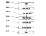
- FIG. 8 is a flowchart of blood vessel detection processing according to the embodiment.
- the irradiation unit 2 irradiates the irradiation position 21 with continuous light through a light shielding plate having a direction adjustment unit for improving the linearity of the irradiation light (step 101).
- the first light intensity detector 31 detects the light intensity at the first detection position 331, and the second light intensity detector 32 detects the light intensity at the second detection position 332 (step 102).
- the control unit 4 calculates in-vivo scattering information based on the light intensity detected by the light detection intensity 3 (step 103).
- control unit 4 calculates the scattering coefficient ⁇ eff by taking the logarithm of the light intensity at a plurality of positions detected by the light intensity detection unit 3.
- the control unit 4 calculates the scattering coefficient ⁇ eff based on the scattering phenomenon in which the irradiated light attenuates due to scattering as the distance to the detection position 33 increases.
- the control unit 4 calculates a light intensity difference or light intensity ratio between the first light intensity at the first detection position 331 and the second light intensity at the second detection position 332, and calculates the light intensity difference or light Absorption information is calculated based on the intensity ratio. Alternatively, the control unit 4 calculates the absorption information from the light intensity at the first detection position 331 or the light intensity at the second detection position 332. (Step 104).
- the control unit 4 calculates blood flow information serving as an index of blood flow from the time change of the absorption information (step 105).
- the control unit 4 may calculate the blood flow information from the amount of change in the light intensity within the measurement time, with the light intensity measurement time being 20 seconds or less.
- the control unit 4 determines that the predetermined part of the living body irradiated with light is the blood vessel position based on the scattering information, the absorption information, and the blood flow information (step 106).
- control unit 4 is a blood vessel position when, for example, the ⁇ eff of 810 nm is the maximum value, the ⁇ eff of 970 nm is the maximum value, and 660 nmAD / 810 nmCV (with respect to ⁇ eff) is the minimum value. Is determined.
- the method for calculating the maximum value of ⁇ eff at 810 nm, the maximum value of ⁇ eff at 970 nm, and the minimum value of 660 nmAD / 810 nmCV has been described above.
- control unit 4 controls the notification unit 5 to sound a buzzer, vibrate, or turn on the lamp (step 106).
- the blood vessel detection device and method of the present embodiment it is possible to determine whether or not the position is a blood vessel based on absorption information and blood flow information.
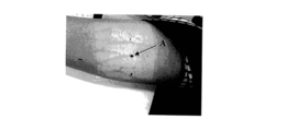
- the blood vessel positioning function in this example was verified.
- a blood vessel detection device was used to mark a place within the reference range of this example, and the vein visualization device was used for confirmation.
- the result is shown in FIG.
- the black point (A in the figure) at the center of the four points indicates the position marked based on the positioning function. As shown in the figure, it was confirmed that the position of the vein was accurately captured.
- FIG. 10 shows a diagram in which the positioning function is applied when no pinhole is used. Compared with FIG. 9, the position of the blood vessel is not accurately detected (B in the figure).
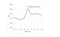
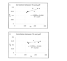
- FIG. 11A shows the result of lipid measurement at a position using the positioning function
- FIG. 11B shows the result of lipid measurement at other positions.
- the correlation coefficient is 0.82, which is a better result than the correlation coefficient of 0.49 in the case of B.
- the above technique can also be used for searching the position of veins and arteries.
Abstract
[Problem] To provide a device and a method that make it possible to identify a blood vessel location. [Solution] The present invention comprises: a radiation unit, which includes a light-blocking plate having a direction adjustment part for enhancing the rectilinearity of radiation light on an irradiated surface, and which irradiates a subject with light of a first wavelength in the absorption band of hemoglobin and with light of a second wavelength that is light of a wavelength the absorption of which by hemoglobin is less than the light of the first wavelength; a light intensity detection unit that detects intensity of light emitted from the subject at one or more locations, the light intensity detection unit being arranged either at a predetermined spacing from a location of light irradiation by the radiation unit or continuously therefrom; and a control unit for calculating scattering information from the light intensity of the light of the second wavelength, calculating absorption information from the light intensity of the light of the first wavelength, calculating blood flow information from the light intensity of the light of the second wavelength, and detecting a blood vessel from the scattering information, the absorption information, and the blood flow information.
Description
本発明は、血管検知装置及びその方法に関する。
The present invention relates to a blood vessel detection device and a method thereof.
食後高脂血症は、動脈硬化のリスクファクターとして注目されている。非空腹時の中性脂肪濃度が高くなると、冠動脈疾患のイベント発症リスクが高くなることが報告されている。
Postprandial hyperlipidemia is attracting attention as a risk factor for arteriosclerosis. It has been reported that an increase in non-fasting neutral fat concentration increases the risk of developing coronary artery disease events.
食後高脂血症の診断は、食後6~8時間の血中の脂質濃度変化を観測する必要がある。つまり、食後の高脂血状態を計測するためには、被験者を6~8時間拘束し、複数回の採血が必要である。そのため、食後高脂血症の診断は臨床研究の域を出ず、食後高脂血症の診断を臨床現場で実施することは、現実的ではなかった。
To diagnose postprandial hyperlipidemia, it is necessary to observe changes in blood lipid levels 6 to 8 hours after meals. In other words, in order to measure the post-meal hyperlipidemia state, the subject must be restrained for 6 to 8 hours, and multiple blood collections are required. For this reason, diagnosis of postprandial hyperlipidemia has not gone out of clinical research, and it has not been realistic to diagnose postprandial hyperlipidemia in the clinical setting.
このような課題を解決する手法が、特許文献1に開示されている。特許文献1の手法によれば、非侵襲脂質計測により、採血を無くすことができる。これにより医療機関のみならず家庭でも血中脂質を計測できるようになる。即時的なデータ取得を可能とすることで、時間的に連続した血中脂質を計測することが可能となる。
A technique for solving such a problem is disclosed in Patent Document 1. According to the method of Patent Document 1, blood collection can be eliminated by noninvasive lipid measurement. As a result, blood lipids can be measured not only at medical institutions but also at home. By enabling immediate data acquisition, it is possible to measure blood lipids continuous in time.
従来の非侵襲脂質計測により血中脂質を計測する手法は、均一系を対象にしている。しかしながら、非侵襲脂質計測は、皮膚や筋肉など、複数の組織から構成される生体計測である。したがって、非侵襲脂質計測において、均一系の理論が有効ではない場合も考えられる。実際に、目視で確認される静脈上での計測値と静脈が目視で確認できない部位の計測値は異なる。これらのことから、非侵襲脂質計測において、最適計測部位が存在すると考えられる。
The conventional method of measuring blood lipids by non-invasive lipid measurement targets a homogeneous system. However, noninvasive lipid measurement is biometric measurement composed of a plurality of tissues such as skin and muscle. Therefore, in non-invasive lipid measurement, there may be a case where the theory of a homogeneous system is not effective. Actually, the measurement value on the vein that is visually confirmed is different from the measurement value of the portion where the vein cannot be visually confirmed. From these facts, it is considered that there is an optimal measurement site in noninvasive lipid measurement.
本発明は、このような従来の問題を解決するためになされたもので、非侵襲的に血中成分を計測するための最適計測部位を検出することが可能な装置及び方法を提供することである。
The present invention has been made to solve such a conventional problem, and provides an apparatus and a method capable of detecting an optimal measurement site for noninvasively measuring blood components. is there.
本発明の血管検知装置は、照射面に照射光の直線性を高めるための方向調整部を有する遮光板を有し、ヘモグロビンの吸収帯の第1波長の光と、第1波長の光より、ヘモグロビンの吸収が小さい波長の光である第2波長の光とを被検体に照射する照射部と、照射部による光の照射位置から所定間隔をあけて、あるいは、連続的に配置されて、被検体から放出される1以上の位置の光強度を検出する光強度検出部と、第2波長の光の光強度から、散乱情報を算出し、第1波長の光の光強度から、吸収情報を算出し、第2波長の光の光強度から、血流情報を算出し、散乱情報と吸収情報と血流情報とから血管を検知する制御部と、を有する。
The blood vessel detection device of the present invention has a light shielding plate having a direction adjusting unit for enhancing the linearity of irradiation light on the irradiation surface, and from the light of the first wavelength in the absorption band of hemoglobin and the light of the first wavelength, An irradiation unit that irradiates the subject with light of a second wavelength, which is light having a small wavelength of absorption of hemoglobin, and a predetermined interval from the irradiation position of the light by the irradiation unit, or continuously disposed, Scattering information is calculated from a light intensity detector that detects the light intensity at one or more positions emitted from the specimen and the light intensity of the second wavelength light, and the absorption information is calculated from the light intensity of the first wavelength light. And a control unit that calculates blood flow information from the light intensity of the light of the second wavelength and detects a blood vessel from the scattered information, the absorption information, and the blood flow information.
また、本発明の血管検知方法は、照射光の直線性を高めるための方向調整部を有する遮光板を介し、ヘモグロビンの吸収帯の第1波長の光と、第1波長の光より、ヘモグロビンの吸収が小さい波長の光である第2波長の光とを被検体に照射し、光の照射位置から所定間隔をあけて、あるいは、連続的な位置での、被検体から放出される1以上の位置の光強度を検出し、第2波長の光の光強度から、散乱情報を算出し、第1波長の光の光強度から、吸収情報を算出し、第2波長の光の光強度から、血流情報を算出し、散乱情報と吸収情報と血流情報とから血管を検知する。
In addition, the blood vessel detection method of the present invention uses the light having the first wavelength in the absorption band of hemoglobin and the light having the first wavelength through the light-shielding plate having a direction adjusting unit for increasing the linearity of the irradiation light. Irradiating the subject with light of a second wavelength, which is light having a small absorption, and at least one or more emitted from the subject at a predetermined interval from the light irradiation position or at continuous positions The light intensity at the position is detected, the scattering information is calculated from the light intensity of the second wavelength light, the absorption information is calculated from the light intensity of the first wavelength light, and the light intensity of the second wavelength light is calculated. Blood flow information is calculated, and blood vessels are detected from the scattered information, absorption information, and blood flow information.
本発明の血管検知装置及び方法によれば、非侵襲血液計測における測定値の正確性、精密性などの精度向上を図ることが可能となる。
According to the blood vessel detection device and method of the present invention, it is possible to improve accuracy such as accuracy and precision of measurement values in noninvasive blood measurement.
以下、実施形態である血管検知装置及びその方法について、図を参照して詳細に説明をする。
Hereinafter, the blood vessel detection apparatus and method according to the embodiment will be described in detail with reference to the drawings.
図1は、実施形態の血管検知装置の構成を示す図である。
FIG. 1 is a diagram illustrating a configuration of a blood vessel detection device according to an embodiment.
図1に示すように、実施形態の血管検知装置1は、照射部2と、光強度検出部3と、制御部4と、通知部5を有する。
As shown in FIG. 1, the blood vessel detection device 1 of the embodiment includes an irradiation unit 2, a light intensity detection unit 3, a control unit 4, and a notification unit 5.
照射部2は、生体の所定の部位の生体外から生体内に向けて、所定の照射位置21に光を照射するための光源22を有する。光源22は、照射する光の波長を調整できる。光源22は、波長範囲を血漿の無機物によって光が吸収される波長範囲以外に調整できる。光源22は、血液の細胞成分によって光が吸収される波長範囲以外に調整できる。ここで、血液の細胞成分とは、血中の赤血球、白血球及び血小板である。血漿の無機物とは、血中の水及び電解質である。
The irradiation unit 2 has a light source 22 for irradiating light to a predetermined irradiation position 21 from outside the living body to a living body at a predetermined part of the living body. The light source 22 can adjust the wavelength of the irradiated light. The light source 22 can adjust the wavelength range other than the wavelength range in which light is absorbed by the plasma inorganic substance. The light source 22 can be adjusted outside the wavelength range in which light is absorbed by cell components of blood. Here, the cell components of blood are red blood cells, white blood cells, and platelets in the blood. Plasma minerals are water and electrolytes in the blood.
実施形態の照射部2は、後述する制御部4による散乱係数μeffの算出方法に応じて、光の連続的な照射や光のパルス状の照射等の光を照射する時間の長さを任意に調整できる。照射部2は、照射する光の強度または光の位相を任意に変調できる。
The irradiation unit 2 of the embodiment can arbitrarily set the length of time for irradiating light such as continuous irradiation of light or pulsed irradiation of light according to the calculation method of the scattering coefficient μeff by the control unit 4 described later. Can be adjusted. The irradiation unit 2 can arbitrarily modulate the intensity of light to be irradiated or the phase of light.
照射部2は、波長が固定された光源22を用いてもよい。照射部2は、波長が異なる複数の光源あるいは複数の波長の光を混合したものであってもよい。照射部2は、例えば、蛍光灯、LED、レーザー、白熱灯、HID、ハロゲンランプ等である。照射部2の照度は、制御部4により制御されてもよいし、別途設けられた制御回路により制御されてもよい。
The irradiation unit 2 may use a light source 22 with a fixed wavelength. The irradiation unit 2 may be a plurality of light sources having different wavelengths or a mixture of light having a plurality of wavelengths. The irradiation unit 2 is, for example, a fluorescent lamp, LED, laser, incandescent lamp, HID, halogen lamp, or the like. The illuminance of the irradiation unit 2 may be controlled by the control unit 4 or may be controlled by a separately provided control circuit.
実施形態では、光源22はLED(Light Emitting Diode)である。光源22は、LEDからの照射光の直線性を高めるための方向調整部23を有する。光源22にLEDをそのまま用いた場合には、照射時における拡散が、いわゆる外乱光と同様に、測定値に誤差を与える可能性がある。さらに、照射光が、生体表面で拡散するため、皮膚などの静脈と光源の間に存在する物質の影響を受けることとなる。
In the embodiment, the light source 22 is an LED (Light Emitting Diode). The light source 22 has a direction adjusting unit 23 for improving the linearity of the irradiation light from the LED. When the LED is used as it is for the light source 22, the diffusion during irradiation may give an error to the measurement value as in the so-called disturbance light. Furthermore, since the irradiated light diffuses on the surface of the living body, it is affected by a substance existing between a vein such as skin and a light source.
実施形態では、照射光の到達深度をコントロールすることで、最適な深さを計測する方法を検証した。生体の皮膚などの組織の散乱係数は1.0/mmとされており、光が1mmの深さに達した時に散乱を開始すると考えられる。図2に示すように、実施形態では、光源22のLEDの発光面に、直径0.8mmのピンホール23aを備えた方向調整部23を設置する。これにより、光源22のLEDから放出される拡散成分を軽減し、光の直進性を高める。
In the embodiment, a method for measuring the optimum depth by controlling the arrival depth of the irradiated light was verified. The scattering coefficient of tissues such as living body skin is 1.0 / mm, and it is considered that scattering starts when the light reaches a depth of 1 mm. As shown in FIG. 2, in the embodiment, a direction adjusting unit 23 including a pinhole 23 a having a diameter of 0.8 mm is installed on the light emitting surface of the LED of the light source 22. Thereby, the diffusion component emitted from the LED of the light source 22 is reduced, and the straightness of light is improved.
なお、ピンホール23aの直径は、好ましくは0.4mm以上1.5mm以下である。この数値範囲とした場合には、拡散を抑制した入射光となる。入射光の光源となるLEDより小さい範囲で照射することで、LED機材の外枠等によるノイズを軽減することができる。1.5mm よりピンホール23aの直径が大きいと、光源22のLEDから放出される拡散成分が大きくなる。0.4mmよりピンホール23aの直径が小さいと、計測上必要とされる入射光強度が得られない可能性がある。
In addition, the diameter of the pinhole 23a is preferably 0.4 mm or more and 1.5 mm or less. In this numerical range, the incident light is suppressed in diffusion. By irradiating in a range smaller than the LED that becomes the light source of incident light, noise caused by the outer frame of the LED equipment can be reduced. When the diameter of the pinhole 23a is larger than 1.5 mm, the diffusion component emitted from the LED of the light source 22 becomes large. If the diameter of the pinhole 23a is smaller than 0.4 mm, the incident light intensity required for measurement may not be obtained.
ピンホール23aの直径は、より好ましくは0.8mm以上1.2mm以下である。この数値範囲とした場合には、擬似的な直線光となり、計測原理となる拡散理論に近似した効果が得られ、さらには計測に必要な光強度を保つことができる。
The diameter of the pinhole 23a is more preferably 0.8 mm or more and 1.2 mm or less. In this numerical range, it becomes pseudo linear light, an effect approximate to the diffusion theory as the measurement principle is obtained, and furthermore, the light intensity necessary for measurement can be maintained.
ピンホール23aの直径は、さらに好ましくは0.8mm以上0.9mm以下である。この数値範囲とした場合には、より擬似的な直線光が得られ、計測原理に則った拡散理論が適用できるという効果が得られる。
The diameter of the pinhole 23a is more preferably 0.8 mm or more and 0.9 mm or less. In this numerical range, more quasi-linear light is obtained, and the effect that a diffusion theory in accordance with the measurement principle can be applied is obtained.
ピンホール23aの効果を確認するため、光学特性を生体と同様に調整(μs=1.0/mm, μa=0.01/mm)した模擬生体を用いて検証した結果を図3に示す。その結果、入射光は約1mmまで侵入した後、光が拡散していることが確認できた(図3のB)。一方、ピンホールが無い場合には、光が表面で拡散してしまっている(図3のA)。このことから、LEDからの照射光が、ピンホール23aを通過し、光の直進性が高まることで、目標とする深度まで光が透過することが可能であることがわかった。
FIG. 3 shows the result of verification using a simulated living body in which the optical characteristics are adjusted in the same manner as the living body (μs = 1.0 / mm, μa = 0.01 / mm) in order to confirm the effect of the pinhole 23a. As a result, it was confirmed that the incident light diffused to about 1 mm and then diffused (B in FIG. 3). On the other hand, when there is no pinhole, the light has diffused on the surface (A in FIG. 3). From this, it was found that the light emitted from the LED passes through the pinhole 23a, and the straightness of the light increases, so that the light can be transmitted to the target depth.
なお、実施形態では、方向調整部23にピンホール23aが備わる態様について説明したが、これに限られない。例えば、方向調整部23は、レンズ等の光学系により光の直線性を高めることが可能な構成を有すればよい。
In addition, although embodiment demonstrated the aspect with which the direction adjustment part 23 was equipped with the pinhole 23a, it is not restricted to this. For example, the direction adjusting unit 23 only needs to have a configuration capable of enhancing the linearity of light by an optical system such as a lens.
実施形態の光源22は、相異なる第1波長の光及び第2波長の光を照射する。第1波長の光は、吸収情報を取得するための光である。第2波長の光は、散乱情報及び血流情報を取得するための光である。
The light source 22 of the embodiment irradiates light having a different first wavelength and light having a second wavelength. The light of the first wavelength is light for acquiring absorption information. The light of the second wavelength is light for acquiring scattering information and blood flow information.
「吸収情報」を取得するための第1波長の光は、血液中のヘモグロビンの吸収帯の波長の光であればよい。例えば、光源22は、第1波長の光として、可視光を照射するのがよい。ヘモグロビンの吸収帯の波長を使用することで、ヘモグロビンに依存した吸収情報が得られる。ヘモグロビンの吸収帯は、400 nm~700nm辺りであり、可視光のほとんどをカバーしている。したがって、光源22の波長範囲は、400 nm~700nmであることが好ましい。
The light having the first wavelength for acquiring “absorption information” may be light having a wavelength in the absorption band of hemoglobin in blood. For example, the light source 22 may emit visible light as the first wavelength light. Absorption information dependent on hemoglobin can be obtained by using the wavelength of the absorption band of hemoglobin. The absorption band of hemoglobin is around 400 nm to 700 nm, covering most of the visible light. Therefore, the wavelength range of the light source 22 is preferably 400 nm to 700 nm.
「散乱情報」及び「血流情報」を取得するための第2波長の光は、第1波長の光より、血液中のヘモグロビンの吸収が少ない帯域の波長の光であればよく、例えば、光源22は、第2波長の光として、近赤外光を照射するのが好ましい。近赤外光は、他にも水など組織に関する吸収が小さいため、血流などの動きの情報を正確に計測しやすい。
The light of the second wavelength for acquiring “scattering information” and “blood flow information” may be light having a wavelength in a band in which the absorption of hemoglobin in blood is less than that of light of the first wavelength. 22 is preferably irradiated with near infrared light as the second wavelength light. Near-infrared light has a small amount of absorption related to other tissues such as water, so that it is easy to accurately measure movement information such as blood flow.
「散乱情報」及び「血流情報」を取得する場合には、光源22の波長範囲は、血漿の無機物により光を吸収する波長範囲を考慮して約1400nm以下、及び、約1500nm~約1860nmであることが好ましい。さらに、光源22の波長範囲は、血液の細胞成分によって光が吸収される波長範囲を考慮して約580nm~約1400nm、及び、約1500nm~約1860nmであることがより好ましい。
When acquiring “scattering information” and “blood flow information”, the wavelength range of the light source 22 is about 1400 nm or less and about 1500 nm to about 1860 nm in consideration of the wavelength range in which light is absorbed by the plasma inorganic substance. Preferably there is. Further, the wavelength range of the light source 22 is more preferably about 580 nm to about 1400 nm and about 1500 nm to about 1860 nm in consideration of the wavelength range in which light is absorbed by the cellular components of blood.
光源22に用いられる波長範囲を、上記範囲とすることにより、後述する光強度検出部3により検出される光において、血漿の無機物による光の吸収の影響、及び、血液の細胞成分により光の吸収の影響を抑制する。これにより、物質を特定するほどの吸収は存在せず、吸収による光エネルギー損失は無視できるほど小さくなる。そのため、血中の光は血中の脂質による散乱によって遠くまで伝搬し、体外へ放出される。
By setting the wavelength range used for the light source 22 to the above range, in the light detected by the light intensity detection unit 3 to be described later, the light absorption effect by the inorganic substance of plasma and the light absorption by the blood cell component. To suppress the effects of Thereby, there is no absorption enough to specify the substance, and the light energy loss due to the absorption becomes so small that it can be ignored. For this reason, light in the blood propagates far away by scattering by lipids in the blood and is emitted outside the body.
実施形態の光源22は、可視光及び近赤外光の双方の光を照射するが、光源22は、可視光を照射する光源と近赤外光を照射する光源との別個の複数の光源を含んでもよい。光源を複数とすることにより、光強度検出部3の受光時に波長の区別を行うことが不要となる。また、光源を複数とする場合には、複数の光源の各々にピンホールを備えた遮光板を設けるのがよい。
The light source 22 of the embodiment emits both visible light and near-infrared light, but the light source 22 includes a plurality of separate light sources, a light source that emits visible light and a light source that emits near-infrared light. May be included. By using a plurality of light sources, it is not necessary to distinguish wavelengths when the light intensity detector 3 receives light. When a plurality of light sources are used, it is preferable to provide a light shielding plate having a pinhole in each of the plurality of light sources.
光強度検出部3は、生体から生体外に放出される光を受光して、その光強度を検出する。複数の光強度検出部3を用いる場合には、光強度検出部3は、照射位置21を略中心として各々異なる距離に設置される。図1に示すように、実施形態では、照射位置21から所定の間隔で同一面上でかつ直線状に、第1の光強度検出部31及び第2の光強度検出部32が順に並べられる。光強度検出部3は、フォトダイオードやCCDやCMOSでよい。
The light intensity detector 3 receives light emitted from the living body to the outside of the living body and detects the light intensity. When a plurality of light intensity detectors 3 are used, the light intensity detectors 3 are installed at different distances with the irradiation position 21 as a substantial center. As shown in FIG. 1, in the embodiment, the first light intensity detection unit 31 and the second light intensity detection unit 32 are sequentially arranged on the same plane and in a straight line at a predetermined interval from the irradiation position 21. The light intensity detector 3 may be a photodiode, CCD, or CMOS.
図1に示すように、実施形態では、照射位置21から第1の光強度検出部31による第1の検出位置331までの距離を第1の照射検出間距離ρ1とする。照射位置21から第2の光強度検出部32による第2の検出位置332までの距離を第2の照射検出間距離ρ2とする。
As shown in FIG. 1, in the embodiment, the distance from the irradiation position 21 to the first detection position 331 by the first light intensity detection unit 31 is defined as a first irradiation detection distance ρ1. The distance from the irradiation position 21 to the second detection position 332 by the second light intensity detection unit 32 is defined as a second irradiation detection distance ρ2.
図4に示すように、光を生体に照射する照射位置21と、生体中の血液(図中のE)から放出される光強度を検出する検出位置31との間に、所定の距離ρを設ける。所定の距離ρを設けることにより、照射した光(図中のA)が生体表面及び表面近傍の散乱体により反射して直接的に生体から放出される光(図中のB)の影響を抑制する。照射した光が、リポ蛋白等の脂質が存在する深さに達したのち、血液中の脂質(図中のD)によって光が反射する。脂質による光の反射による散乱を経て、生体から放出される後方散乱光(図中のC)による光強度を検出する。また、照射位置21と検出位置31との距離ρを長くすることで、光路長は長くなる。このため、脂質との衝突回数が増え、検出される光は散乱の影響を多く受ける。このように、距離ρを長くすることにより、これまでは弱く、検出しにくかった散乱の影響を捉えやすくなる。
As shown in FIG. 4, a predetermined distance ρ is set between an irradiation position 21 for irradiating the living body with light and a detection position 31 for detecting the light intensity emitted from blood (E in the figure) in the living body. Provide. By providing a predetermined distance ρ, the irradiated light (A in the figure) is reflected by the scatterer in the surface of the living body and in the vicinity of the surface, and the influence of light (B in the figure) directly emitted from the living body is suppressed. To do. After the irradiated light reaches a depth where lipids such as lipoproteins are present, the light is reflected by lipids in blood (D in the figure). The light intensity by backscattered light (C in the figure) emitted from the living body is detected through scattering due to reflection of light by lipid. Further, the optical path length is increased by increasing the distance ρ between the irradiation position 21 and the detection position 31. For this reason, the number of collisions with lipids increases, and the detected light is greatly affected by scattering. In this way, by increasing the distance ρ, it becomes easier to capture the influence of scattering that has been weak and difficult to detect.
また、図5に示すように、照射部2と光強度検出部3とで生体(図中のE)を挟み込み、照射部2からの光を光強度検出部3が検出する配置でもよい。
Moreover, as shown in FIG. 5, the living body (E in the figure) may be sandwiched between the irradiation unit 2 and the light intensity detection unit 3, and the light intensity detection unit 3 may detect the light from the irradiation unit 2.
計測対象であるリポ蛋白は、アポ蛋白等に覆われた球状構造をしている。リポ蛋白は血中において固体のような状態で存在する。リポ蛋白は、光を反射する性質を有する。特に、粒子径や比重の大きいカイロミクロン(CM)やVLDL等は中性脂肪(TG)を多く含み、光をより散乱させ易い特性を有する。よって、光強度検出部3により検出される光強度には、リポ蛋白による光の散乱の影響が含まれる。
The lipoprotein to be measured has a spherical structure covered with apoprotein or the like. Lipoprotein exists in a solid state in blood. Lipoprotein has the property of reflecting light. In particular, chylomicron (CM), VLDL, and the like having a large particle size and specific gravity contain a lot of neutral fat (TG) and have a characteristic that light is more easily scattered. Therefore, the light intensity detected by the light intensity detector 3 includes the influence of light scattering by lipoproteins.
なお、複数の検出位置31を設ける場合の配列は、照射位置21を略中心として各々異なる距離に配置されるのであれば、直線状に限定されるものではなく、円状、波状、ジグザグ状など、適宜選択することができる。また、照射位置21から検出位置31までの第1の照射検出間距離ρ1や第2の照射検出間距離ρ2、検出位置331、332同士の間隔は、一定の間隔に限定されるものではなく、連続的でもよい。
Note that the arrangement in the case of providing a plurality of detection positions 31 is not limited to a straight line as long as they are arranged at different distances with the irradiation position 21 as a substantial center, and are circular, wavy, zigzag, etc. Can be appropriately selected. Further, the first irradiation detection distance ρ1 and the second irradiation detection distance ρ2 from the irradiation position 21 to the detection position 31 and the interval between the detection positions 331 and 332 are not limited to a fixed interval. It may be continuous.
次に、血管検知装置1の制御系の構成について説明する。図6は実施形態の血管検知装置1のブロック図である。システムバス42を介して、CPU(Central Processing Unit)41、ROM(Read Only Memory)43、RAM(Random Access Memory)44、記憶部45、外部I/F(Interface)46、照射部2、光強度検出部3、及び、通知部5が接続される。CPU41とROM43とRAM44とで制御部(コントローラー)4を構成する。
Next, the configuration of the control system of the blood vessel detection device 1 will be described. FIG. 6 is a block diagram of the blood vessel detection device 1 of the embodiment. Via a system bus 42, a CPU (Central Processing Unit) 41, a ROM (Read Only Memory) 43, a RAM (Random Access Memory) 44, a storage unit 45, an external I / F (Interface) 46, an irradiation unit 2, and light intensity The detection unit 3 and the notification unit 5 are connected. The CPU 41, the ROM 43, and the RAM 44 constitute a control unit (controller) 4.
ROM43は、CPU41により実行されるプログラムや閾値を予め記憶する。
The ROM 43 stores a program executed by the CPU 41 and a threshold value in advance.
RAM44は、CPU41が実行するプログラムを展開するエリアと、プログラムによるデータ処理の作業領域となるワークエリアなどの様々なメモリエリア等を有する。
The RAM 44 has various memory areas such as an area for expanding a program executed by the CPU 41 and a work area serving as a work area for data processing by the program.
記憶部45は、検知・算出された光強度等やμeff等のデータを記憶する。記憶部45は、HDD(Hard Disk Drive)や、フラッシュメモリや、SSD(Solid State Drive)等の、不揮発性に記憶する内部メモリーでよい。
The storage unit 45 stores data such as the detected and calculated light intensity and μeff. The storage unit 45 may be an internal memory that stores data in a nonvolatile manner, such as an HDD (Hard Disk Drive), a flash memory, or an SSD (Solid State Drive).
外部I/F46は、例えばクライアント端末(PC)などの外部装置と通信するためのインターフェースである。外部I/F46は、外部装置とデータ通信を行うインターフェースであれば良く、たとえば、外部装置にローカルに接続する機器(USBメモリ等)であっても良いし、ネットワークを介して通信するためのネットワークインターフェイスであっても良い。
The external I / F 46 is an interface for communicating with an external device such as a client terminal (PC). The external I / F 46 may be an interface that performs data communication with an external device. For example, the external I / F 46 may be a device (such as a USB memory) locally connected to the external device, or a network for communicating via a network. It may be an interface.
制御部4は、光検出強度3により検出された光強度に基づき生体内における散乱情報を算出する。散乱情報は、所定の波長の照射光における光強度検出部3の検出強度に基づき算出される。実施形態では、散乱情報は、光源22の照射光の波長が810nm及び970nmにおける光強度検出部3の検出強度に基づき算出される。
The control unit 4 calculates in-vivo scattering information based on the light intensity detected by the light detection intensity 3. The scattering information is calculated based on the detection intensity of the light intensity detector 3 in the irradiation light with a predetermined wavelength. In the embodiment, the scattering information is calculated based on the detection intensity of the light intensity detection unit 3 when the wavelength of the irradiation light of the light source 22 is 810 nm and 970 nm.
散乱情報は生体内物質に対する吸収が小さい、もしくは、ほとんどない波長(第2波長)を使用して散乱体に対しての情報を得る。この散乱情報は血中脂質の量に依存した情報である。
Scattering information is obtained with respect to the scatterer using a wavelength (second wavelength) with little or no absorption with respect to the substance in the living body. This scattered information is information depending on the amount of lipid in the blood.
散乱情報の一つとして、散乱係数μeffが含まれる。ここで、散乱係数μeffの算出法を説明する。
As one of the scattering information, the scattering coefficient μeff is included. Here, a method of calculating the scattering coefficient μeff will be described.
図1に示すように、実施形態における制御部4は、光強度比又は光強度差を算出する。
As shown in FIG. 1, the control unit 4 in the embodiment calculates a light intensity ratio or a light intensity difference.
制御部4は、光強度検出部3により検出された複数位置の光強度の対数をとり散乱係数μeffを算出する。制御部4は、照射した光が、検出位置33までの距離を遠くするにつれて散乱により減衰していく散乱現象に基づき散乱係数μeffを算出する。
The control unit 4 calculates the scattering coefficient μeff by taking the logarithm of the light intensity at a plurality of positions detected by the light intensity detection unit 3. The control unit 4 calculates the scattering coefficient μeff based on the scattering phenomenon in which the irradiated light attenuates due to scattering as the distance to the detection position 33 increases.
照射部2により所定の光強度の連続光を照射し、制御部4は、第1の光強度検出部31により検出された光照射部と光強度検出部の間の距離ρと、ρの2乗と光強度R(ρ)の積からから、散乱係数μeffを算出する(数式1)。
The irradiation unit 2 emits continuous light with a predetermined light intensity, and the control unit 4 determines the distance ρ between the light irradiation unit and the light intensity detection unit detected by the first light intensity detection unit 31 and 2 of ρ. The scattering coefficient μeff is calculated from the product of the power and the light intensity R (ρ) (Formula 1).

なお、制御部4による散乱係数μeffの算出方法は、上記の各算出法によるものに限定されない。
In addition, the calculation method of the scattering coefficient μeff by the control unit 4 is not limited to the above calculation method.
制御部4は、光強度検出部3により検出された光強度に基づき生体内における吸収情報を算出する。
The control unit 4 calculates absorption information in the living body based on the light intensity detected by the light intensity detection unit 3.
吸収情報は、ヘモグロビンの吸収帯の波長(第1波長)を使用することで得られた、ヘモグロビンに依存した情報である。このヘモグロビンの情報を、血液の情報として使用する。位置決めに用いる吸収情報の取得のための波長は、血液中のヘモグロビンの吸収帯である可視光を用いることが望ましい。一方、血流情報を確認する場合は、近赤外光が望ましい。近赤外光は、水など組織に関する吸収が小さいため、血流などの動きの情報を正確に計測しやすい。
The absorption information is information dependent on hemoglobin obtained by using the wavelength of the absorption band of hemoglobin (first wavelength). This hemoglobin information is used as blood information. It is desirable to use visible light that is an absorption band of hemoglobin in blood as a wavelength for acquiring absorption information used for positioning. On the other hand, when confirming blood flow information, near infrared light is desirable. Near-infrared light has a small absorption with respect to tissues such as water, and therefore, it is easy to accurately measure movement information such as blood flow.
吸収情報は、所定の波長の照射光における光強度検出部3の検出強度である。実施形態では、吸収情報は、光源22の照射光の波長が660nmである場合に、光強度検出部3が検出した光強度である。
The absorption information is the detection intensity of the light intensity detector 3 in the irradiation light of a predetermined wavelength. In the embodiment, the absorption information is the light intensity detected by the light intensity detector 3 when the wavelength of the light emitted from the light source 22 is 660 nm.
計測対象となる血液は、皮膚組織などと異なり、血管内を流動している。この血流により得られる動的パラメータを血流情報と定義する。実施形態では、分析に当たり一定時間計測することで、血流情報を算出し、血管位置を判定する。
Measured blood is flowing in blood vessels, unlike skin tissue. A dynamic parameter obtained by this blood flow is defined as blood flow information. In the embodiment, blood flow information is calculated by measuring for a certain time in analysis, and the blood vessel position is determined.
血流情報は、生体内物質に対する吸収が小さい、もしくは、ほとんどない波長(第2波長)を使用して、散乱体に対して得られた情報である。
Blood flow information is information obtained with respect to a scatterer using a wavelength (second wavelength) with little or no absorption with respect to in-vivo substances.
制御部4は、標準偏差や、ブラウン運動や、自己相関関数や、周波数解析や、スペックルや、ドップラーシフトや、レイノルズ数や、血流量や、血液量や、脈動幅などを用いて分析し、血液の動きを計測する指標である血流情報を算出する。制御部4は、光強度の計測時間を20sec以下とし、この計測時間内における光強度の変化量から、血流情報を算出してもよい。
The control unit 4 analyzes using standard deviation, Brownian motion, autocorrelation function, frequency analysis, speckle, Doppler shift, Reynolds number, blood flow, blood volume, pulsation width, etc. Blood flow information, which is an index for measuring blood movement, is calculated. The control unit 4 may calculate the blood flow information from the amount of change in the light intensity within the measurement time, with the light intensity measurement time being 20 seconds or less.
従来は、計測対象部位を計測するにあたり、時間による計測値の変動量には着目せず、平均化させた値を採用していた。しかしながら、血液計測において静脈などの血液が豊富な部位や密集している部位を計測した方が、血液情報が多く含まれるため、ノイズ要因が少なくなる。非侵襲計測において、入射した光が静脈を透過したかどうかを判断するには血流により得られる情報を取得することが望ましい。
Conventionally, when measuring a measurement target part, an averaged value is used without paying attention to a fluctuation amount of a measured value with time. However, in blood measurement, measuring blood-rich parts such as veins or dense parts contains a lot of blood information, resulting in fewer noise factors. In non-invasive measurement, it is desirable to acquire information obtained by blood flow in order to determine whether or not incident light has transmitted through a vein.
しかしながら、脈など、心拍による周期性を計測する場合、動脈が望ましいとされる。そのため、静脈を計測対象とする場合の位置決めは、一定時間内における、血流による受光強度の時間変化のばらつきを計測することが望ましい。
However, when measuring periodicity due to a heartbeat, such as a pulse, an artery is desirable. Therefore, it is desirable to measure the variation in the temporal change in the received light intensity due to the blood flow within a certain period of time when positioning the vein as the measurement target.
すなわち、拍動の周期(0.5~2.0Hz程度)が観測される場合は、皮膚層は、脂質計測に適した生体の部位であるといえる。一方、拍動の周期が見られず、周期性のない血流情報が静脈の位置を示す(少なくとも静脈情報に依存している)情報となり、静脈は、脂質計測に適した生体の部位であるといえる。
That is, when the period of pulsation (about 0.5 to 2.0 Hz) is observed, it can be said that the skin layer is a body part suitable for lipid measurement. On the other hand, the pulsation period is not seen, and blood flow information with no periodicity becomes information indicating the position of the vein (at least depends on the vein information), and the vein is a part of a living body suitable for lipid measurement. It can be said.
なお、上記情報を区別するためには、光強度検出部のサンプリングレートは、10msec以下が望ましく、分解能は16bit以上が望ましい。
In order to distinguish the above information, the sampling rate of the light intensity detector is desirably 10 msec or less, and the resolution is desirably 16 bits or more.
血流情報の一つとして、散乱係数μeffの変動係数CVが含まれる。
As one of the blood flow information, the variation coefficient CV of the scattering coefficient μeff is included.
制御部4は、算出された散乱係数μeffの時間変化から、散乱係数μeffの変動係数CVを算出する。変動係数CVについては、例えば、以下の数式2により算出できる。
The control unit 4 calculates the variation coefficient CV of the scattering coefficient μeff from the time change of the calculated scattering coefficient μeff. The variation coefficient CV can be calculated by, for example, Equation 2 below.

光強度の標準偏差は以下の数式3で求められる。
The standard deviation of the light intensity is obtained by the following formula 3.

ここで、<>は、平均を表す
, Where <> represents the average
変動係数CVを算出するために、散乱係数μeffを計測する時間としては、1msec以上30sec以下、好ましくは、5msec以上25sec以下、さらに好ましくは10msec以上20sec以下とするのがよい。(なお、「sec」は「秒」の略である。)
In order to calculate the coefficient of variation CV, the time for measuring the scattering coefficient μeff is 1 msec or more and 30 sec or less, preferably 5 msec or more and 25 sec or less, more preferably 10 msec or more and 20 sec or less. ("Sec" is an abbreviation for "second".)
制御部4は、散乱情報、吸収情報及び血流情報を算出して、散乱情報、吸収情報及び血流情報から血管位置を判定する。
The control unit 4 calculates scattering information, absorption information, and blood flow information, and determines a blood vessel position from the scattering information, absorption information, and blood flow information.
実施形態は、2次元的(平面的)に血管位置を探索する装置・方法を提供する。図7に示したように、静脈上では他の部位に比較し、散乱が強くなるため血管位置として検出することが見込まれる。しかしながら、散乱の強さは、血管の太さや血管の深さも関係していることから、一概に吸収だけで計測することはできない。実際に脂質計測結果が良好であった場合とそうでなかった場合の位置決め機能を比較すると、受光強度の乱れに差異が見られた。これは、静脈の血流を反映していると想定される。また、この血流情報は、最適計測条件に対し深すぎると、皮膚層などにより緩和されてしまう。
The embodiment provides an apparatus and a method for searching a blood vessel position in a two-dimensional (planar) manner. As shown in FIG. 7, it is expected that the blood vessel position is detected on the vein because the scattering is stronger than that on other parts. However, since the intensity of scattering is related to the thickness of the blood vessel and the depth of the blood vessel, it cannot be measured by absorption alone. When the positioning function was compared between when the lipid measurement result was actually good and when it was not, there was a difference in the disturbance of the received light intensity. This is assumed to reflect venous blood flow. In addition, if the blood flow information is too deep with respect to the optimum measurement condition, the blood flow information is relaxed by the skin layer or the like.
実施形態では、LEDを使用し、ピンホールやレンズを使用し直線性を高めた平行光を入射し、血液による吸収情報と血流情報を組み合わせることで、血管位置を事前に検知することができる。
In the embodiment, a blood vessel position can be detected in advance by using LED, inputting parallel light with improved linearity using a pinhole or a lens, and combining absorption information by blood and blood flow information. .
計測対象となる血液は、皮膚組織などと異なり、血管内を流動している。実施形態では、分析に当たり一定時間計測することで、血流情報を算出し、さらに光路に含まれるすべての散乱を示す吸収情報を算出し、これら2つのパラメータから、各個人における血管位置を判定する。
Measured blood is flowing in blood vessels, unlike skin tissue. In the embodiment, blood flow information is calculated by measuring for a certain time in the analysis, absorption information indicating all scattering included in the optical path is calculated, and the blood vessel position in each individual is determined from these two parameters. .
また、吸収情報及び血流情報の取得は、通信回線を介したものに限定されるものではなく、手入力してもよい。
Also, the acquisition of absorption information and blood flow information is not limited to that via a communication line, and may be manually input.
制御部4は、散乱情報として810nmのμeff(μeffは有効散乱係数。以下同じ)が最大であることを検知する。
The control unit 4 detects that the μeff of 810 nm (μeff is an effective scattering coefficient; the same applies hereinafter) is the maximum as the scattering information.
ここで、810nmは、血流情報取得用に光源22から発せられる照射光の波長である。この波長のμeffの情報が血中の濁度に依存した情報になる。
Here, 810 nm is the wavelength of irradiation light emitted from the light source 22 for blood flow information acquisition. The information of μeff of this wavelength becomes information depending on turbidity in blood.
μeffは、第1の光強度検出部31及び第2の光強度検出部32が検出した光強度から上記の数式1により求めることができる。
Μeff can be obtained from the light intensity detected by the first light intensity detection unit 31 and the second light intensity detection unit 32 according to Equation 1 above.
ここで、ρは照射位置からの距離、R(ρ)はその距離における光散乱強度(この装置においては検出フォトダイオードの測定値)である。適用すると上式の傾きがμeffとなる。
Here, ρ is the distance from the irradiation position, and R (ρ) is the light scattering intensity at that distance (measured value of the detection photodiode in this apparatus). When applied, the slope of the above equation becomes μeff.
被験者上での任意の範囲における測定において、光強度を複数回検出すると、μeffの値が測定位置に応じて変化する。制御部4は、前回のμeffの値と比較してμeffの値が高い場合に保存されているμeffの値を書き換える処理を行う。これにより、制御部4は、結果として自動的に位置探索の範囲での810nmのμeffの値の最大値を記憶する。
In measurement in an arbitrary range on the subject, if the light intensity is detected a plurality of times, the value of μeff changes according to the measurement position. The control unit 4 performs a process of rewriting the value of μeff stored when the value of μeff is higher than the previous value of μeff. As a result, the control unit 4 automatically stores the maximum value of μeff of 810 nm in the position search range as a result.
制御部4は、散乱情報として970nmのμeffが最大であることを検知する。
The control unit 4 detects that the μeff at 970 nm is the maximum as the scattering information.
ここで、970nmは、血流情報取得用に光源22から発せられる照射光の波長である。この波長のμeffの情報が血中の濁度に依存した情報になる。
Here, 970 nm is a wavelength of irradiation light emitted from the light source 22 for blood flow information acquisition. The information of μeff of this wavelength becomes information depending on turbidity in blood.
μeffは、第1の光強度検出部31及び第2の光強度検出部32が検出した光強度から上記数式2により求めることができる。μeffの求め方については上記した。
Μeff can be obtained from the light intensity detected by the first light intensity detection unit 31 and the second light intensity detection unit 32 according to the above formula 2. The method for obtaining μeff has been described above.
被験者上での任意の範囲における測定において、光強度を複数回検出すると、μeffの値が測定位置に応じて変化する。制御部4は、前回のμeffの値と比較してμeffの値が高い場合に保存されているμeffの値を書き換える処理を行う。これにより、制御部4は、結果として自動的に位置探索の範囲での970nmのμeffの値の最大値を記憶する。
In measurement in an arbitrary range on the subject, if the light intensity is detected a plurality of times, the value of μeff changes according to the measurement position. The control unit 4 performs a process of rewriting the value of μeff stored when the value of μeff is higher than the previous value of μeff. As a result, the control unit 4 automatically stores the maximum value of the μeff value of 970 nm in the position search range.
制御部4は、660nmAD/810nmCVが最小であることを検知する。
The control unit 4 detects that 660 nm AD / 810 nm CV is minimum.
ここで、660nmADは吸収情報である。具体的には660nmの光が照射された時の、一番距離的に近い第1の光強度検出部31又は第2の光強度検出部32の測定値である。
, Where 660nmAD is absorption information. Specifically, it is a measurement value of the first light intensity detection unit 31 or the second light intensity detection unit 32 that is closest in distance when 660 nm light is irradiated.
810nmCVは血流情報である。照射光の波長が810nmのときのμeffの変動係数CVである。
810nmCV is blood flow information. This is the coefficient of variation CV of μeff when the wavelength of irradiation light is 810 nm.
なお、810nm,970nm波長は、光散乱計測を行い散乱体の粒子サイズによって最適波長を選んだものである。また、660nm波長は、ヘモグロビンの吸収検出用の波長である。
For 810nm and 970nm wavelengths, light scattering measurement was performed and the optimum wavelength was selected according to the particle size of the scatterer. The wavelength of 660 nm is a wavelength for detecting absorption of hemoglobin.
被験者上での任意の範囲における測定において、光強度を複数回検出すると、660nmAD/810nmCVの値が測定位置に応じて変化する。制御部4は、前回の660nmAD/810nmCVの値と比較して660nmAD/810nmCVの値が小さい場合に保存されている660nmAD/810nmCVの値を書き換える処理を行う。これにより、制御部4は、結果として自動的に位置探索の範囲での660nmAD/810nmCVの値の最小値を記憶する。
In measurement in an arbitrary range on the subject, when the light intensity is detected a plurality of times, the value of 660 nmAD / 810 nmCV changes depending on the measurement position. The control unit 4 performs a process of rewriting the stored value of 660 nmAD / 810 nmCV when the value of 660 nmAD / 810 nmCV is smaller than the previous value of 660 nmAD / 810 nmCV. As a result, the control unit 4 automatically stores the minimum value of the values of 660 nmAD / 810 nmCV in the position search range as a result.
制御部4は、散乱情報としての810nmのμeffが最大値であり、かつ、散乱情報としての970nmのμeffが最大値であり、かつ、吸収情報と血流情報の比660nmAD/810nmCVが最小値である場合に、非侵襲脂質計測において、良好なデータが取得できる血管位置である場所と判断する。
The control unit 4 has a maximum value of 810 nm μeff as scattering information, a maximum value of 970 nm μeff as scattering information, and a minimum value of the ratio of absorption information to blood flow information 660 nmAD / 810 nmCV. In some cases, in noninvasive lipid measurement, it is determined that the location is a blood vessel position where good data can be acquired.
実施形態の通知部5は、ブザー、バイブレータ、ランプ等である。制御部4が血管を検知に適した部位であると判別した場合に、制御部4は、通知部5にブザーを鳴らさせる、振動させる、又は、ランプを点灯させる。これにより、血管位置であることをユーザに通知する。
The notification unit 5 of the embodiment is a buzzer, a vibrator, a lamp, or the like. When the control unit 4 determines that the blood vessel is a part suitable for detection, the control unit 4 causes the notification unit 5 to sound a buzzer, vibrate, or turn on a lamp. This notifies the user that it is a blood vessel position.
以上のような構成を備える血管検知装置1において、予め設定されているプログラムに基づいて、血管検知装置1は血管検知処理を実行する。図8は、実施形態の血管検知処理のフローチャートである。
In the blood vessel detection device 1 having the above-described configuration, the blood vessel detection device 1 executes blood vessel detection processing based on a preset program. FIG. 8 is a flowchart of blood vessel detection processing according to the embodiment.
照射部2が、照射光の直線性を高めるための方向調整部を有する遮光板を介し、照射位置21に連続光を照射する(ステップ101)。
The irradiation unit 2 irradiates the irradiation position 21 with continuous light through a light shielding plate having a direction adjustment unit for improving the linearity of the irradiation light (step 101).
第1の光強度検出部31が第1の検出位置331における光強度を検出するとともに、第2の光強度検出部32が第2の検出位置332の光強度を検出する(ステップ102)。
The first light intensity detector 31 detects the light intensity at the first detection position 331, and the second light intensity detector 32 detects the light intensity at the second detection position 332 (step 102).
制御部4は光検出強度3により検出された光強度に基づき生体内における散乱情報を算出する(ステップ103)。
The control unit 4 calculates in-vivo scattering information based on the light intensity detected by the light detection intensity 3 (step 103).
例えば、制御部4は、光強度検出部3により検出された複数位置の光強度の対数をとり散乱係数μeffを算出する。制御部4は、照射した光が、検出位置33までの距離を遠くするにつれて散乱により減衰していく散乱現象に基づき散乱係数μeffを算出する。
For example, the control unit 4 calculates the scattering coefficient μeff by taking the logarithm of the light intensity at a plurality of positions detected by the light intensity detection unit 3. The control unit 4 calculates the scattering coefficient μeff based on the scattering phenomenon in which the irradiated light attenuates due to scattering as the distance to the detection position 33 increases.
制御部4は、第1の検出位置331における第1の光強度と、第2の検出位置332における第2の光強度との光強度差若しくは光強度比を算出し、当該光強度差若しくは光強度比に基づいて吸収情報を算出する。もしくは、制御部4は第1の検出位置331における光強度、もしくは、第2の検出位置332の光強度から吸収情報を算出する。(ステップ104)。
The control unit 4 calculates a light intensity difference or light intensity ratio between the first light intensity at the first detection position 331 and the second light intensity at the second detection position 332, and calculates the light intensity difference or light Absorption information is calculated based on the intensity ratio. Alternatively, the control unit 4 calculates the absorption information from the light intensity at the first detection position 331 or the light intensity at the second detection position 332. (Step 104).
制御部4は、吸収情報の時間変化から血液流動の指標となる血流情報を算出する(ステップ105)。制御部4は、光強度の計測時間を20sec以下とし、この計測時間内における光強度の変化量から、血流情報を算出してもよい。
The control unit 4 calculates blood flow information serving as an index of blood flow from the time change of the absorption information (step 105). The control unit 4 may calculate the blood flow information from the amount of change in the light intensity within the measurement time, with the light intensity measurement time being 20 seconds or less.
制御部4は、散乱情報、吸収情報及び血流情報に基づいて、光を照射した生体の所定の部位は血管位置と判定する(ステップ106)。
The control unit 4 determines that the predetermined part of the living body irradiated with light is the blood vessel position based on the scattering information, the absorption information, and the blood flow information (step 106).
例えば、制御部4は、例えば、810nmのμeffが最大値であり、かつ、970nmのμeffが最大値であり、かつ、660nmAD/810nmCV(μeffに対する)が最小値である場合に、血管位置であると判別する。なお、810nmのμeffの最大値、970nmのμeffの最大値、及び、660nmAD/810nmCVの最小値の算出法については上記した。
For example, the control unit 4 is a blood vessel position when, for example, the μeff of 810 nm is the maximum value, the μeff of 970 nm is the maximum value, and 660 nmAD / 810 nmCV (with respect to μeff) is the minimum value. Is determined. The method for calculating the maximum value of μeff at 810 nm, the maximum value of μeff at 970 nm, and the minimum value of 660 nmAD / 810 nmCV has been described above.
制御部4は、血管位置であると判別した場合に、通知部5に、ブザーを鳴らす、振動させる、又は、ランプを点灯させる制御を行う(ステップ106)。
When it is determined that the position is a blood vessel position, the control unit 4 controls the notification unit 5 to sound a buzzer, vibrate, or turn on the lamp (step 106).
以上説明したように、本実施形態の血管検知装置及び方法によれば、吸収情報及び血流情報に基づいて、血管位置か否かを判定することが可能となる。
As described above, according to the blood vessel detection device and method of the present embodiment, it is possible to determine whether or not the position is a blood vessel based on absorption information and blood flow information.
以下に、本発明の実施例について説明するが、本発明は、下記の実施例に限定されない。
Examples of the present invention will be described below, but the present invention is not limited to the following examples.
市販の静脈可視化装置を使用し、本実施例における血管位置決め機能の検証を行った。まず、血管検知装置を使用し、本実施例の基準範囲に入った場所にマーキングし、静脈可視化装置で確認した。その結果を図9に示す。ここでは4つの点の中心にある黒点(図中のA)が位置決め機能に基づいてマーキングされた位置を示している。図に示すように、静脈の位置が的確にとらえられていることが確認できた。
Using a commercially available vein visualization device, the blood vessel positioning function in this example was verified. First, a blood vessel detection device was used to mark a place within the reference range of this example, and the vein visualization device was used for confirmation. The result is shown in FIG. Here, the black point (A in the figure) at the center of the four points indicates the position marked based on the positioning function. As shown in the figure, it was confirmed that the position of the vein was accurately captured.
また、図10は、ピンホールを用いない場合で位置決め機能を適用した図を示す。図9と比べると血管の位置を正確に検出していない(図中のB)。
FIG. 10 shows a diagram in which the positioning function is applied when no pinhole is used. Compared with FIG. 9, the position of the blood vessel is not accurately detected (B in the figure).
また、図11のAは、位置決め機能を用いたポジションで脂質計測を行った結果を示し、図11のBは、それ以外のポジションで脂質計測を行った結果を示す図である。Aに示すように、相関係数0.82であり、Bの場合の相関係数0.49に比べて良好な結果が得られた。
FIG. 11A shows the result of lipid measurement at a position using the positioning function, and FIG. 11B shows the result of lipid measurement at other positions. As shown in A, the correlation coefficient is 0.82, which is a better result than the correlation coefficient of 0.49 in the case of B.
上記技術は、静脈や動脈の位置を探索することにも利用可能である。
The above technique can also be used for searching the position of veins and arteries.
また受光部を、受光素子をアレイ状やCCDカメラ、CMOSカメラなどにすることで、二次元情報を取得し、上記条件1,2に記載の最適位置をプログラムで自動検出することも可能である。
It is also possible to obtain two-dimensional information by using a light receiving element in the form of an array, a CCD camera, a CMOS camera, etc., and automatically detect the optimum position described in the above conditions 1 and 2 with a program. .
以上、実施形態を説明したが、この実施形態は、例として提示したものであり、発明の範囲を限定することは意図していない。この新規な実施形態は、その他の様々な形態で実施されることが可能であり、発明の要旨を逸脱しない範囲で、種々の省略、置き換え、変更を行うことができる。この実施形態やその変形は、発明の範囲や要旨に含まれるとともに、特許請求の範囲に記載された発明とその均等の範囲に含まれる。
As mentioned above, although embodiment was described, this embodiment is shown as an example and is not intending limiting the range of invention. The novel embodiment can be implemented in various other forms, and various omissions, replacements, and changes can be made without departing from the spirit of the invention. This embodiment and its modifications are included in the scope and gist of the invention, and are included in the invention described in the claims and the equivalents thereof.
1 血管検知装置
2 照射部
3 光強度検出部
4 制御部
5 通知部 DESCRIPTION OFSYMBOLS 1 Blood vessel detection apparatus 2 Irradiation part 3 Light intensity detection part 4 Control part 5 Notification part
2 照射部
3 光強度検出部
4 制御部
5 通知部 DESCRIPTION OF
Claims (10)
- 照射面に照射光の直線性を高めるための方向調整部を有する遮光板を有し、ヘモグロビンの吸収帯の第1波長の光と、前記第1波長の光より、ヘモグロビンの吸収が小さい波長の光である第2波長の光と、を被検体に照射する照射部と、
前記照射部による光の照射位置から所定間隔をあけて、あるいは、連続的に配置されて、前記被検体から放出される1以上の位置の光強度を検出する光強度検出部と、
前記第2波長の光の光強度から、散乱情報を算出し、
前記第1波長の光の光強度から、吸収情報を算出し、
前記第2波長の光の光強度から、血流情報を算出し、
前記散乱情報と前記吸収情報と前記血流情報とから血管を検知する制御部と、
を有する血管検知装置。 A light-shielding plate having a direction adjustment unit for increasing the linearity of the irradiation light on the irradiation surface, the light having the first wavelength in the absorption band of hemoglobin and the light having a smaller absorption of hemoglobin than the light having the first wavelength An irradiation unit that irradiates the subject with light of a second wavelength that is light;
A light intensity detector that detects the light intensity at one or more positions emitted from the subject at a predetermined interval from the irradiation position of the light by the irradiation unit or continuously arranged;
Scatter information is calculated from the light intensity of the second wavelength light,
Absorption information is calculated from the light intensity of the light of the first wavelength,
Blood flow information is calculated from the light intensity of the second wavelength light;
A control unit for detecting blood vessels from the scattering information, the absorption information, and the blood flow information;
A blood vessel detection device having - 前記第1波長の光は可視光であり、前記第2波長の光は近赤外光である、ことを特徴とする請求項1に記載の血管検知装置。 The blood vessel detection device according to claim 1, wherein the first wavelength light is visible light, and the second wavelength light is near infrared light.
- 前記制御部は、
前記散乱情報が最大値であり、前記吸収情報を前記血流情報で除した値が最小値である場合に、血管検知と判定する請求項1または2に記載の血管検知装置。 The controller is
The blood vessel detection device according to claim 1, wherein blood vessel detection is determined when the scattering information is a maximum value and a value obtained by dividing the absorption information by the blood flow information is a minimum value. - 前記散乱情報は、散乱係数であり、
前記制御部は、
前記光強度検出部により検出された複数位置の光強度の比、又は、複数位置の光強度の差、に基づいて生体内における前記散乱係数を算出する、請求項1から3のいずれかに記載の血管検知装置。 The scattering information is a scattering coefficient,
The controller is
4. The scattering coefficient in the living body is calculated based on a ratio of light intensities at a plurality of positions detected by the light intensity detector or a difference in light intensities at a plurality of positions. 5. Blood vessel detection device. - 前記制御部は、
前記第1波長の照射光における前記光強度検出部の検出強度に基づいて前記吸収情報を算出する請求項1から4のいずれかに記載の血管検知装置。 The controller is
The blood vessel detection device according to claim 1, wherein the absorption information is calculated based on a detection intensity of the light intensity detection unit in the irradiation light of the first wavelength. - 前記血流情報は、前記散乱係数の変動係数であり、
前記制御部は、
前記散乱係数の所定時間における変化から、前記変動係数を算出する、請求項4に記載の血管検知装置。 The blood flow information is a variation coefficient of the scattering coefficient,
The controller is
The blood vessel detection device according to claim 4, wherein the variation coefficient is calculated from a change in the scattering coefficient at a predetermined time. - 前記所定時間は、10msec以上20sec以下である請求項6に記載の血管検知装置。 The blood vessel detection device according to claim 6, wherein the predetermined time is 10 msec or more and 20 sec or less.
- 前記方向調整部は、ピンホールまたはレンズを有することを特徴とする請求項1から7のいずれかに記載の血管検知装置。 The blood vessel detection device according to any one of claims 1 to 7, wherein the direction adjustment unit includes a pinhole or a lens.
- 前記ピンホールの直径は、0.4mm以上1.5mm以下である請求項8に記載の血管検知装置。 The blood vessel detection device according to claim 8, wherein the pinhole has a diameter of 0.4 mm or more and 1.5 mm or less.
- 照射光の直線性を高めるための方向調整部を有する遮光板を介し、ヘモグロビンの吸収帯の第1波長の光と、前記第1波長の光より、ヘモグロビンの吸収が小さい波長の光である第2波長の光とを被検体に照射し、
前記光の照射位置から所定間隔をあけて、あるいは、連続的な位置での、前記被検体から放出される1以上の位置の光強度を検出し、
前記第2波長の光の光強度から、散乱情報を算出し、
前記第1波長の光の光強度から、吸収情報を算出し、
前記第2波長の光の光強度から、血流情報を算出し、
前記散乱情報と前記吸収情報と前記血流情報とから血管を検知する、血管検知方法。 The light having the first wavelength in the absorption band of hemoglobin and the light having a wavelength that has less absorption of hemoglobin than the light of the first wavelength through a light shielding plate having a direction adjusting unit for increasing the linearity of the irradiation light. Irradiate the subject with light of two wavelengths,
Detecting the light intensity at one or more positions emitted from the subject at a predetermined interval from the irradiation position of the light or at continuous positions;
Scatter information is calculated from the light intensity of the second wavelength light,
Absorption information is calculated from the light intensity of the light of the first wavelength,
Blood flow information is calculated from the light intensity of the second wavelength light;
A blood vessel detection method for detecting a blood vessel from the scattered information, the absorption information, and the blood flow information.
Priority Applications (3)
| Application Number | Priority Date | Filing Date | Title |
|---|---|---|---|
| CN201980034273.9A CN112153940A (en) | 2018-05-22 | 2019-05-21 | Blood vessel detection device and method thereof |
| EP19807340.5A EP3797687A4 (en) | 2018-05-22 | 2019-05-21 | Blood vessel detection device and method therefor |
| US17/050,880 US20210196135A1 (en) | 2018-05-22 | 2019-05-21 | Blood vessel detection device and method therefor |
Applications Claiming Priority (2)
| Application Number | Priority Date | Filing Date | Title |
|---|---|---|---|
| JP2018097589A JP7093963B2 (en) | 2018-05-22 | 2018-05-22 | Blood vessel detector |
| JP2018-097589 | 2018-05-22 |
Publications (1)
| Publication Number | Publication Date |
|---|---|
| WO2019225612A1 true WO2019225612A1 (en) | 2019-11-28 |
Family
ID=68617002
Family Applications (1)
| Application Number | Title | Priority Date | Filing Date |
|---|---|---|---|
| PCT/JP2019/020142 WO2019225612A1 (en) | 2018-05-22 | 2019-05-21 | Blood vessel detection device and method therefor |
Country Status (6)
| Country | Link |
|---|---|
| US (1) | US20210196135A1 (en) |
| EP (1) | EP3797687A4 (en) |
| JP (1) | JP7093963B2 (en) |
| KR (1) | KR20190133107A (en) |
| CN (1) | CN112153940A (en) |
| WO (1) | WO2019225612A1 (en) |
Cited By (1)
| Publication number | Priority date | Publication date | Assignee | Title |
|---|---|---|---|---|
| WO2021153490A1 (en) * | 2020-01-28 | 2021-08-05 | メディカルフォトニクス株式会社 | Blood vessel detection device and method therefor |
Families Citing this family (2)
| Publication number | Priority date | Publication date | Assignee | Title |
|---|---|---|---|---|
| WO2021145375A1 (en) * | 2020-01-17 | 2021-07-22 | メディカルフォトニクス株式会社 | Device and method for measuring blood lipid level |
| CN113349767B (en) * | 2021-05-26 | 2024-02-23 | 北京麦邦光电仪器有限公司 | Detection probe, electronic device and blood component detection method |
Citations (7)
| Publication number | Priority date | Publication date | Assignee | Title |
|---|---|---|---|---|
| JP2013544151A (en) * | 2010-11-16 | 2013-12-12 | ギブン イメージング リミテッド | In vivo imaging apparatus and method for performing spectral analysis |
| WO2014087825A1 (en) | 2012-12-06 | 2014-06-12 | 国立大学法人北海道大学 | Non-invasive biolipid concentration meter, non-invasive biolipid metabolism measuring device, non-invasive method for measuring biolipid concentration, and non-invasive method for examining biolipid metabolism |
| WO2016208010A1 (en) * | 2015-06-24 | 2016-12-29 | 浜松ホトニクス株式会社 | Scattering absorber measurement device and scattering absorber measurement method |
| JP2017113461A (en) * | 2015-12-25 | 2017-06-29 | 株式会社東芝 | Measuring device, measurement method, and program |
| WO2017119130A1 (en) * | 2016-01-08 | 2017-07-13 | 株式会社三菱ケミカルホールディングス | Non-invasive biological lipid measuring instrument and non-invasive biological lipid measuring method |
| WO2017141895A1 (en) * | 2016-02-18 | 2017-08-24 | メディカルフォトニクス株式会社 | Physical condition management device and method for same |
| WO2017199492A1 (en) * | 2016-05-18 | 2017-11-23 | メディカルフォトニクス株式会社 | Blood lipid level measurement device and method for operating same |
Family Cites Families (9)
| Publication number | Priority date | Publication date | Assignee | Title |
|---|---|---|---|---|
| US6939310B2 (en) * | 2001-10-10 | 2005-09-06 | Lifescan, Inc. | Devices for physiological fluid sampling and methods of using the same |
| JP4061409B2 (en) * | 2004-11-09 | 2008-03-19 | 国立大学法人九州大学 | Sensor unit and biosensor |
| US11253198B2 (en) * | 2006-01-10 | 2022-02-22 | Accuvein, Inc. | Stand-mounted scanned laser vein contrast enhancer |
| US9445766B1 (en) * | 2009-07-08 | 2016-09-20 | Vioptix, Inc. | Methods for locating a blood vessel |
| JP5990906B2 (en) * | 2011-12-19 | 2016-09-14 | ソニー株式会社 | Measuring device, measuring method, program, and recording medium |
| WO2013148753A1 (en) * | 2012-03-28 | 2013-10-03 | Wayne State University | Sensor and method for continuous health monitoring |
| US20160235303A1 (en) * | 2013-10-11 | 2016-08-18 | The Trustees Of Columbia University In The City Of New York | System, method and computer-accessible medium for characterization of tissue |
| US10165955B2 (en) | 2014-02-06 | 2019-01-01 | Reuven Gladshtein | Obtaining cardiovascular parameters using arterioles related transient time |
| JP6907475B2 (en) * | 2016-07-15 | 2021-07-21 | 富士フイルムビジネスイノベーション株式会社 | Biometric information measuring device and biometric information measuring program |
-
2018
- 2018-05-22 JP JP2018097589A patent/JP7093963B2/en active Active
-
2019
- 2019-05-20 KR KR1020190058891A patent/KR20190133107A/en unknown
- 2019-05-21 CN CN201980034273.9A patent/CN112153940A/en not_active Withdrawn
- 2019-05-21 EP EP19807340.5A patent/EP3797687A4/en not_active Withdrawn
- 2019-05-21 WO PCT/JP2019/020142 patent/WO2019225612A1/en unknown
- 2019-05-21 US US17/050,880 patent/US20210196135A1/en active Pending
Patent Citations (7)
| Publication number | Priority date | Publication date | Assignee | Title |
|---|---|---|---|---|
| JP2013544151A (en) * | 2010-11-16 | 2013-12-12 | ギブン イメージング リミテッド | In vivo imaging apparatus and method for performing spectral analysis |
| WO2014087825A1 (en) | 2012-12-06 | 2014-06-12 | 国立大学法人北海道大学 | Non-invasive biolipid concentration meter, non-invasive biolipid metabolism measuring device, non-invasive method for measuring biolipid concentration, and non-invasive method for examining biolipid metabolism |
| WO2016208010A1 (en) * | 2015-06-24 | 2016-12-29 | 浜松ホトニクス株式会社 | Scattering absorber measurement device and scattering absorber measurement method |
| JP2017113461A (en) * | 2015-12-25 | 2017-06-29 | 株式会社東芝 | Measuring device, measurement method, and program |
| WO2017119130A1 (en) * | 2016-01-08 | 2017-07-13 | 株式会社三菱ケミカルホールディングス | Non-invasive biological lipid measuring instrument and non-invasive biological lipid measuring method |
| WO2017141895A1 (en) * | 2016-02-18 | 2017-08-24 | メディカルフォトニクス株式会社 | Physical condition management device and method for same |
| WO2017199492A1 (en) * | 2016-05-18 | 2017-11-23 | メディカルフォトニクス株式会社 | Blood lipid level measurement device and method for operating same |
Non-Patent Citations (1)
| Title |
|---|
| See also references of EP3797687A4 |
Cited By (1)
| Publication number | Priority date | Publication date | Assignee | Title |
|---|---|---|---|---|
| WO2021153490A1 (en) * | 2020-01-28 | 2021-08-05 | メディカルフォトニクス株式会社 | Blood vessel detection device and method therefor |
Also Published As
| Publication number | Publication date |
|---|---|
| US20210196135A1 (en) | 2021-07-01 |
| JP2019201760A (en) | 2019-11-28 |
| EP3797687A1 (en) | 2021-03-31 |
| EP3797687A4 (en) | 2022-01-26 |
| CN112153940A (en) | 2020-12-29 |
| KR20190133107A (en) | 2019-12-02 |
| JP7093963B2 (en) | 2022-07-01 |
Similar Documents
| Publication | Publication Date | Title |
|---|---|---|
| US20240057883A1 (en) | Deep tissue flowmetry using diffuse speckle contrast analysis | |
| WO2019225612A1 (en) | Blood vessel detection device and method therefor | |
| JP6700042B2 (en) | Real-time tumor perfusion imaging during radiotherapy procedures | |
| TWI770119B (en) | Scatter measurement device and method thereof | |
| JP6894088B2 (en) | Scatterer concentration measuring device and its method | |
| TWI773713B (en) | Lipid measurement device and method therefor | |
| WO2015174273A1 (en) | Breast measurement method and measurement device | |
| JP5420163B2 (en) | Biological measuring device | |
| US20230058347A1 (en) | Blood vessel detection device and method therefor | |
| US20200245929A1 (en) | Lipid measuring apparatus and lipid measuring method | |
| RU2545814C1 (en) | Method of determining physical-biological parameters of skin and concentration of haemoglobin derivatives in blood | |
| RU2622997C1 (en) | Method for blood oxygenation measurement | |
| WO2020080409A1 (en) | Particle concentration measurement device, particle concentration measurement program, and particle concentration measurement method | |
| WO2019208718A1 (en) | Lipid concentration measurement device and method therefor |
Legal Events
| Date | Code | Title | Description |
|---|---|---|---|
| 121 | Ep: the epo has been informed by wipo that ep was designated in this application |
Ref document number: 19807340 Country of ref document: EP Kind code of ref document: A1 |
|
| NENP | Non-entry into the national phase |
Ref country code: DE |
|
| ENP | Entry into the national phase |
Ref document number: 2019807340 Country of ref document: EP Effective date: 20201222 |