WO2019220790A1 - 受信装置、および通信システム - Google Patents
受信装置、および通信システム Download PDFInfo
- Publication number
- WO2019220790A1 WO2019220790A1 PCT/JP2019/014070 JP2019014070W WO2019220790A1 WO 2019220790 A1 WO2019220790 A1 WO 2019220790A1 JP 2019014070 W JP2019014070 W JP 2019014070W WO 2019220790 A1 WO2019220790 A1 WO 2019220790A1
- Authority
- WO
- WIPO (PCT)
- Prior art keywords
- adjustment value
- adjustment
- transmission
- compensation circuit
- circuit
- Prior art date
- Legal status (The legal status is an assumption and is not a legal conclusion. Google has not performed a legal analysis and makes no representation as to the accuracy of the status listed.)
- Ceased
Links
Images




Classifications
-
- H—ELECTRICITY
- H04—ELECTRIC COMMUNICATION TECHNIQUE
- H04L—TRANSMISSION OF DIGITAL INFORMATION, e.g. TELEGRAPHIC COMMUNICATION
- H04L25/00—Baseband systems
- H04L25/02—Details ; arrangements for supplying electrical power along data transmission lines
- H04L25/03—Shaping networks in transmitter or receiver, e.g. adaptive shaping networks
- H04L25/03006—Arrangements for removing intersymbol interference
- H04L25/03012—Arrangements for removing intersymbol interference operating in the time domain
- H04L25/03114—Arrangements for removing intersymbol interference operating in the time domain non-adaptive, i.e. not adjustable, manually adjustable, or adjustable only during the reception of special signals
- H04L25/03146—Arrangements for removing intersymbol interference operating in the time domain non-adaptive, i.e. not adjustable, manually adjustable, or adjustable only during the reception of special signals with a recursive structure
-
- H—ELECTRICITY
- H04—ELECTRIC COMMUNICATION TECHNIQUE
- H04B—TRANSMISSION
- H04B3/00—Line transmission systems
- H04B3/02—Details
- H04B3/04—Control of transmission; Equalising
-
- H—ELECTRICITY
- H04—ELECTRIC COMMUNICATION TECHNIQUE
- H04B—TRANSMISSION
- H04B3/00—Line transmission systems
- H04B3/02—Details
- H04B3/04—Control of transmission; Equalising
- H04B3/10—Control of transmission; Equalising by pilot signal
-
- H—ELECTRICITY
- H04—ELECTRIC COMMUNICATION TECHNIQUE
- H04J—MULTIPLEX COMMUNICATION
- H04J3/00—Time-division multiplex systems
-
- H—ELECTRICITY
- H04—ELECTRIC COMMUNICATION TECHNIQUE
- H04L—TRANSMISSION OF DIGITAL INFORMATION, e.g. TELEGRAPHIC COMMUNICATION
- H04L12/00—Data switching networks
- H04L12/28—Data switching networks characterised by path configuration, e.g. LAN [Local Area Networks] or WAN [Wide Area Networks]
- H04L12/40—Bus networks
- H04L12/40143—Bus networks involving priority mechanisms
-
- H—ELECTRICITY
- H04—ELECTRIC COMMUNICATION TECHNIQUE
- H04L—TRANSMISSION OF DIGITAL INFORMATION, e.g. TELEGRAPHIC COMMUNICATION
- H04L25/00—Baseband systems
- H04L25/02—Details ; arrangements for supplying electrical power along data transmission lines
- H04L25/03—Shaping networks in transmitter or receiver, e.g. adaptive shaping networks
- H04L25/03006—Arrangements for removing intersymbol interference
- H04L25/03012—Arrangements for removing intersymbol interference operating in the time domain
-
- H—ELECTRICITY
- H04—ELECTRIC COMMUNICATION TECHNIQUE
- H04L—TRANSMISSION OF DIGITAL INFORMATION, e.g. TELEGRAPHIC COMMUNICATION
- H04L25/00—Baseband systems
- H04L25/02—Details ; arrangements for supplying electrical power along data transmission lines
- H04L25/03—Shaping networks in transmitter or receiver, e.g. adaptive shaping networks
- H04L25/03006—Arrangements for removing intersymbol interference
- H04L25/03178—Arrangements involving sequence estimation techniques
- H04L25/03248—Arrangements for operating in conjunction with other apparatus
- H04L25/03254—Operation with other circuitry for removing intersymbol interference
- H04L25/03267—Operation with other circuitry for removing intersymbol interference with decision feedback equalisers
-
- H—ELECTRICITY
- H04—ELECTRIC COMMUNICATION TECHNIQUE
- H04L—TRANSMISSION OF DIGITAL INFORMATION, e.g. TELEGRAPHIC COMMUNICATION
- H04L25/00—Baseband systems
- H04L25/02—Details ; arrangements for supplying electrical power along data transmission lines
- H04L25/03—Shaping networks in transmitter or receiver, e.g. adaptive shaping networks
- H04L25/03878—Line equalisers; line build-out devices
- H04L25/03885—Line equalisers; line build-out devices adaptive
-
- H—ELECTRICITY
- H04—ELECTRIC COMMUNICATION TECHNIQUE
- H04L—TRANSMISSION OF DIGITAL INFORMATION, e.g. TELEGRAPHIC COMMUNICATION
- H04L25/00—Baseband systems
- H04L25/02—Details ; arrangements for supplying electrical power along data transmission lines
- H04L25/03—Shaping networks in transmitter or receiver, e.g. adaptive shaping networks
- H04L25/03891—Spatial equalizers
- H04L25/03949—Spatial equalizers equalizer selection or adaptation based on feedback
-
- H—ELECTRICITY
- H04—ELECTRIC COMMUNICATION TECHNIQUE
- H04L—TRANSMISSION OF DIGITAL INFORMATION, e.g. TELEGRAPHIC COMMUNICATION
- H04L25/00—Baseband systems
- H04L25/02—Details ; arrangements for supplying electrical power along data transmission lines
- H04L25/14—Channel dividing arrangements, i.e. in which a single bit stream is divided between several baseband channels and reassembled at the receiver
Definitions
- the present disclosure relates to a receiving device and a communication system.
- the transmission line connected to the reception device Is required by the number of transmission devices.
- a configuration in which the transmission device and the reception device are connected by a transmission line a configuration in which a plurality of transmission devices and one reception device are connected to the transmission line and a data signal is transmitted in a time-division manner (hereinafter, This configuration is referred to as a “multipoint bus”).
- a multipoint bus When using a multipoint bus to connect each of a plurality of transmitting devices and one receiving device with a transmission line, the number of transmission lines connected to the receiving device can be reduced from the number of transmitting devices. It is.
- the transmission line impedance and the delay amount between each transmitting device and the receiving device are different. Therefore, when a data signal is transmitted using a multipoint bus, “every time a transmission device that transmits a data signal is switched, an adjustment amount in a compensation circuit such as an equalizer provided in the reception device is changed. “Adjusting according to the transmitting device to be transmitted” is performed. As described above, by “adjusting the compensation circuit according to the transmission device that transmits the data signal”, the signal quality is reduced due to the difference in the transmission line impedance and the delay amount between the transmission device and the reception device. It is possible to prevent.
- a compensation circuit that is connected to a transmission line to which a plurality of transmission devices are respectively connected, compensates for a signal transmitted in a time division manner from each of the transmission devices, and an adjustment circuit that adjusts the operation of the compensation circuit. And the adjustment circuit adjusts the operation of the compensation circuit according to the first adjustment value read from the recording medium storing the first adjustment value for adjusting the operation of the compensation circuit.
- the reception device includes a plurality of transmission devices that are respectively connected to the transmission line, and a reception device that is connected to the transmission line and receives a signal transmitted from each of the transmission devices.
- An apparatus includes a compensation circuit that is connected to the transmission line and compensates a signal transmitted in a time division manner from each of the transmission apparatuses, and an adjustment circuit that adjusts an operation of the compensation circuit, and the adjustment circuit includes the compensation circuit.
- a communication system is provided that adjusts the operation of the compensation circuit according to the first adjustment value read from a recording medium in which a first adjustment value for adjusting the operation of the circuit is stored.
- Communication system Decrease in signal transmission efficiency that occurs in a communication system using an existing multipoint bus [2] To improve signal transmission efficiency in the communication system according to the present embodiment [3] Example of configuration of receiving apparatus according to this embodiment [4] Example of processing in communication system according to this embodiment [5] Performance achieved by using communication system having receiving apparatus according to this embodiment [6] Application example of communication system, transmission device, and reception device according to this embodiment
- the transmitting device may be indicated as “TX” and the receiving device may be indicated as “RX”.
- FIG. 1 is an explanatory diagram illustrating an example of a configuration of a communication system 1000 according to the present embodiment.
- Examples of the communication system 1000 include a drone (a device that can be operated by a remote operation or an autonomous operation), a moving body such as an automobile, and the like. Note that the application example of the communication system 1000 is not limited to the example described above. Other application examples of the communication system 1000 will be described later.
- the communication system 1000 includes, for example, transmission devices 100A, 100B, 100C, 100D, 100E,.
- the receiving device 200 includes power supplied from an internal power source (not shown) such as a battery, or the communication system 1000. It is driven by power supplied from an external power source.
- the transmitting devices 100A, 100B, 100C, 100D, 100E,... are collectively referred to, or one of the transmitting devices 100A, 100B, 100C, 100D, 100E,. 100 ”.
- the number of transmission devices included in the communication system according to the present embodiment is not limited to the example shown in FIG.
- the communication system according to the present embodiment may include two or more arbitrary numbers of transmission apparatuses 100.
- the transmission line is a transmission path for one signal that connects each of the transmission device 100 and the reception device 200.
- each transmission device 100 transmits a data signal in a time division manner, and is transmitted from each transmission device 100 to the reception device 200 via a transmission line. That is, the transmission line is a multipoint bus that connects each of the plurality of transmission devices 100 and the reception device 200.
- the transmitting device 100 is a device having a function of transmitting a data signal through at least a transmission path.
- the transmission apparatus 100 includes a device according to an application example of a transmission apparatus according to this embodiment described later, such as a sensor device, and has a function according to the application example of the transmission apparatus according to this embodiment described later. You may do it.
- examples of the sensor device according to the present embodiment include imaging devices such as a digital still camera, a digital video camera, and a stereo camera, an infrared sensor, and a distance image sensor.
- the transmission device 100 functions as an image sensor.
- the transmission device 100 functions as an image sensor and transmits image data as a data signal will be described as an example.
- the receiving device 200 is a device having a function of receiving a data signal through at least a transmission path.
- the receiving device 200 may have a function according to an application example of the receiving device according to the present embodiment described later. An example of the configuration of the receiving device 200 will be described later.
- each of the transmission devices transmits a data signal in a time division manner in order to avoid collision of data output from each of the plurality of transmission devices. That is, when a multipoint bus is used, each transmission device transmits a data signal at a different timing.
- the transmission line impedance and delay amount between each transmitting device and receiving device are different.
- a training signal and a data signal are transmitted each time a transmission apparatus that transmits a data signal is switched. That is, a transmission device that constitutes a communication system using an existing multipoint bus transmits a training signal each time a data signal is transmitted.
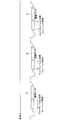
- FIG. 2 is an explanatory diagram showing an example of a signal transmitted in a communication system using an existing multipoint bus.
- a shown in FIG. 2 shows an example of a signal transmitted by a transmitting apparatus connected to the same position as the transmitting apparatus 100A shown in FIG. B shown in FIG. 2 shows an example of a signal transmitted by a transmitting apparatus connected to the same position as the transmitting apparatus 100B shown in FIG. C shown in FIG. 2 shows an example of a signal transmitted by a transmitting apparatus connected to the same position as the transmitting apparatus 100C shown in FIG.
- FIG. 2 shows an example in which each of transmission apparatuses that constitute a communication system using an existing multipoint bus transmits a signal indicating image data as a data signal.
- each transmission apparatus transmits a training signal and a data signal in a time division manner.
- each time a receiving device receives a training signal the receiving device calibrates a compensation circuit (described later) using the received training signal, and receives the signal after calibration.
- the processed data signal is processed.
- FIG. 3 is a block diagram illustrating an example of a configuration of the receiving device 20 that configures a communication system in which an existing multipoint bus is used.
- the receiving device 20 includes, for example, a compensation circuit 22, an adjustment circuit 24, and a processing circuit 26.
- the compensation circuit 22 is a circuit having a function of compensating a received signal.
- the compensation circuit 22 includes, for example, a CTLE (Continuous Time Linear Equalizer) 28 and a DFE (Decision Feedback Equalizer) 30.
- the CTLE 28 is an amplifier circuit having a frequency characteristic that compensates for the frequency characteristic of the transmission line, for example.
- the CTLE 28 can cleanly shape the signal waveform by adjusting the frequency characteristics.
- the DFE 30 includes, for example, a determination unit (hereinafter referred to as “sampler”) that determines a logical value of a received signal, and a circuit (tap) that gives a delay and a weight to the sampled signal.
- the delay and weight applied to the sampled signal is adjusted by one or both of the tap coefficient and the tap number.
- the DFE 30 can finely compensate the received signal by adjusting the number of taps to increase the number of taps, for example.
- the adjustment circuit 24 is a circuit having a function of adjusting the operation of the compensation circuit 22.
- the adjustment circuit 24 adjusts the operation of the compensation circuit 22 by adjusting the frequency characteristic of the CTLE 28 and adjusting one or both of the tap coefficient and the number of taps of the DFE 30, for example.
- the adjustment circuit 24 sets an adjustment value for adjusting the operation of the compensation circuit 22 based on the training signal compensated by the compensation circuit 22. For example, the adjustment circuit 24 detects an eye opening from an eye diagram based on the compensated training signal, and sets an adjustment value based on the detection result of the eye opening.
- the adjustment circuit 24 adjusts the frequency characteristic of the CTLE 28 according to the adjustment value for adjusting the set CTLE 28, and the tap coefficient of the DFE 30 according to the adjustment value for adjusting the set DFE 30. Adjust one or both with the number of taps.
- the processing circuit 26 is a circuit having a function of processing the data signal compensated by the compensation circuit 22.
- the processing circuit 26 includes, for example, a sampler and a processor that performs arbitrary processing on the sampled data signal.
- the receiving device 20 constituting the communication system using the existing multipoint bus has the configuration shown in FIG. 3, for example, and calibrates the compensation circuit 22 using the received training signal. Process the signal.
- the receiving device 20 must calibrate the compensation circuit 22 using the received training signal every time the transmitting device that transmits the data signal is switched. For this reason, in a communication system using an existing multipoint bus, it takes time to switch between transmission apparatuses that transmit data signals, and the total bandwidth in which data signals can be transmitted in a certain period is reduced.
- the receiving device 200 switches the compensation circuit every time the transmitting device 100 that transmits the data signal is switched.
- the calibration of the compensation circuit (described later) included in the receiving apparatus 200 is performed using the adjustment value stored in the recording medium.
- the adjustment value according to the present embodiment includes, for example, an adjustment value for adjusting the operation of the compensation circuit.
- the adjustment value for adjusting the operation of the compensation circuit among the adjustment values according to the present embodiment may be referred to as “first adjustment value”.
- an adjustment value for waveform correction in the receiving device 200 can be cited.
- an adjustment value for waveform correction for example, one of a value for adjusting capacitance / resistance value (high frequency boost amount) constituting CTLE and a value for setting the number of tap stages of DFE or Both are mentioned.
- the first adjustment value may be an equalizer adjustment value itself for waveform correction, such as a value indicating the number of DFE taps, or a value associated with the adjustment value by a table or the like. (For example, ID etc.) may be sufficient.
- the example of the first adjustment value is not limited to the example shown above.
- the first adjustment value may include a value for performing delay setting in a PDC (Programmable Delay Controller).
- a value for performing delay setting in the PDC can be specified based on, for example, a value indicating a BER (Bit Error Rate) of a sampled signal.
- BER Bit Error Rate
- the adjustment value according to the present embodiment is not limited to the first adjustment value (the adjustment value for adjusting the operation of the compensation circuit).
- the adjustment value according to the present embodiment may include an adjustment value for adjusting the operation of the transmission device 100. That is, the receiving apparatus 200 can adjust the operation of the transmitting apparatus 100.
- the adjustment value for adjusting the operation of the transmission device 100 among the adjustment values according to the present embodiment may be referred to as a “second adjustment value”.
- the second adjustment value (adjustment value for adjusting the operation of the transmission device 100) according to the present embodiment, for example, an adjustment value of an FIR (Finite Impulse Response) filter that constitutes the transmission device 100 may be cited.
- the adjustment value of the FIR filter there is a value for setting the number of taps of the FIR filter.
- the example of the second adjustment value is not limited to the example shown above.
- the adjustment value according to the present embodiment is an eye based on a training signal transmitted from the transmission apparatus 100, similarly to the adjustment value in the communication system using the existing multipoint bus described with reference to FIGS. -It is set based on the detection result of the eye opening detected from the diagram. Since the adjustment value is set based on the training signal, the adjustment value is set for each transmission device 100 that transmits the training signal. An example of processing related to the adjustment value setting will be described later.
- the adjustment value according to the present embodiment may be a value set at the time of manufacturing the receiving device 200, for example.
- Examples of the recording medium in which the adjustment value is stored include a recording medium included in the receiving apparatus 200, or a recording medium external to the receiving apparatus 200 that can be read by the receiving apparatus 200.
- the training signal is transmitted in a time-sharing manner from each of the transmission devices 100 during a period in which the data signal is not transmitted (first period).
- Examples of the period in which the data signal is not transmitted in the communication system 1000 according to the present embodiment include an invalid data period in which an adjustment value can be set based on a training signal (an invalid data period in which a training time can be secured).
- Specific examples of the period during which the data signal is not transmitted include, for example, “a predetermined period set from the time when power supply to each device of the communication system 1000 is started (so-called power-on time)”, “ Vertical blanking period (V blank) "and the like.
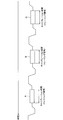
- FIG. 4 is an explanatory diagram showing an example of training signal transmission in the communication system 1000 according to the present embodiment.
- a shown in FIG. 4 shows an example of a training signal transmitted by the transmitting apparatus 100A, for example.
- B illustrated in FIG. 4 illustrates an example of a training signal transmitted by the transmission device 100B, for example.
- C illustrated in FIG. 4 illustrates an example of a training signal transmitted by the transmission device 100C, for example.
- a training signal is transmitted in a time division manner from each of the transmission devices 100.
- FIG. 4 an example in which the training signal is transmitted in order from the transmission device 100 having a short communication distance with the reception device 200 in the multipoint bus is shown.
- the order of the transmission device 100 that transmits the training signal is as described above. It is not restricted to the example shown in.
- the training signals may be transmitted in an arbitrary order in which transmission of the training signals in time division can be realized.
- the receiving device 200 that receives a training signal transmitted in time division from each of the transmitting devices 100 receives an adjustment value ("first adjustment value” or, based on the received training signal, every time a training signal is received. “First adjustment value and second adjustment value”) is set. That is, for example, as indicated by “calibration section” in FIG. 4, a section corresponding to the training signal corresponds to a period for setting the adjustment value based on the training signal.
- the data signal is transmitted in a time-sharing manner from each of the transmission devices 100, as in the communication system using the existing multipoint bus described with reference to FIGS.
- FIG. 5 is an explanatory diagram showing an example of data signal transmission in the communication system 1000 according to the present embodiment.
- a illustrated in FIG. 5 illustrates an example of a data signal transmitted by the transmission device 100A, for example.
- B illustrated in FIG. 5 illustrates an example of a data signal transmitted by the transmission device 100B, for example.
- C illustrated in FIG. 5 illustrates an example of a data signal transmitted by the transmission device 100C, for example.
- FIG. 5 illustrates an example in which each transmission apparatus 100 transmits a signal indicating image data as a data signal.
- the receiving apparatus 200 that receives the data signal transmitted in a time-sharing manner from each of the transmitting apparatuses 100, for example, receives the first adjustment value from the recording medium in a period corresponding to the section indicated as “recording medium read setting section” in FIG. (Adjustment value for adjusting the operation of the compensation circuit) is read.
- the receiving apparatus 200 adjusts the operation of the compensation circuit based on the first adjustment value read from the recording medium.
- a period corresponding to a section indicated as “recording medium read setting section” in FIG. 5 corresponds to a period before the data signal transmitted from the transmission apparatus 100 is received (second period). That is, for example, the reception device 200 reads the first adjustment value (the adjustment value for adjusting the operation of the compensation circuit) from the recording medium in a period before the data signal transmitted from the transmission device 100 is received. It is possible.
- the timing at which the receiving apparatus 200 reads the first adjustment value (the adjustment value for adjusting the operation of the compensation circuit) from the recording medium is not limited to the example illustrated with reference to FIG.
- the receiving apparatus 200 can read out the first adjustment value (adjustment value for adjusting the operation of the compensation circuit) from the recording medium when a predetermined reading timing is detected.
- the first adjustment value adjustment value for adjusting the operation of the compensation circuit
- Examples of the predetermined read timing according to the present embodiment include the following examples. Needless to say, the example of the predetermined read timing is not limited to the example shown below. Timing when switching to a predetermined operation mode such as the LP (Low Power) mode in the D-PHY standard of MIPI Alliance is detected.
- LP Low Power
- Reception device based on reception of synchronization signal (vertical synchronization signal, horizontal synchronization signal, etc.) The timing at which the counter value of the internal counter 200 reaches a predetermined value; the timing at which a known code is received; the timing at which the transmission device 100 transmitting the data signal detects the end of transmission of the data signal; The timing at which transmission of the data signal is detected in the transmission device 100 that transmits the data signal next to the transmission device 100 that is transmitting the data signal;
- the compensation circuit is based on the first adjustment value (adjustment value for adjusting the operation of the compensation circuit) read from the recording medium in the period corresponding to the section indicated as “recording medium readout setting section” in FIG.
- the compensation circuit is calibrated.
- the receiving apparatus 200 processes a data signal received after calibration.
- the second adjustment value adjustment value for adjusting the operation of the transmission device 100
- the data transmitted by the adjusted transmission device 100 in the reception device 200 is adjusted.
- the signal can be processed.
- the receiving device 200 constituting the communication system 1000 is “calibrating the compensation circuit every time the transmitting device that transmits the data signal is switched, such as the receiving device 20 constituting the communication system using the existing multipoint bus”. ”Is not performed. Therefore, in the communication system 1000 including the receiving device 200, signal transmission efficiency can be improved as compared with a communication system using an existing multipoint bus.
- the receiving device 200 “in the case where a data signal is transmitted through a transmission line to which the plurality of transmitting devices 100 and the receiving device 200 are connected, prevention of signal quality degradation and signal transmission efficiency”. A communication system that can improve the performance is realized.
- FIG. 6 is a block diagram illustrating an example of the configuration of the receiving device 200 that configures the communication system 1000 according to the present embodiment.
- FIG. 7 is an explanatory diagram illustrating an example of a signal waveform processed in the receiving apparatus 200 according to the present embodiment, and the signal waveform is represented by an eye diagram.
- Each of the signal waveforms shown in A of FIG. 7, B of FIG. 7, and C of FIG. 7 is an example of a signal waveform of a signal at each of the positions of A of FIG. 6, B of FIG. 6, and C of FIG.
- the receiving apparatus 200 includes, for example, a compensation circuit 202, an adjustment circuit 204, a processing circuit 106, and a recording medium 208.
- the compensation circuit 202 is a circuit having a function of compensating a received signal.
- the compensation circuit 202 includes, for example, a CTLE 210, a DFE 212, a PDC 214, and a PDC 216.
- Each of CTLE 210 and DFE 212 compensates for a signal in the same manner as CTLE 28 and DFE 30 included in compensation circuit 22 shown in FIG. As shown in FIG. 7B and FIG. 7C, it can be seen that the signal is compensated in the compensation circuit 202 to widen the eye opening and improve the signal reception characteristics.
- the PDC 214 delays the signal transmitted from the DFE 212 according to the delay setting.
- the PDC 216 delays the clock signal CLK according to the delay setting.
- the receiving apparatus 200 can perform DeSkew adjustment. Note that when the receiving apparatus 200 does not have a function of performing DeSkew adjustment, the compensation circuit 202 may not include the PDC 214 and the PDC 216.
- Adjustment circuit 204 is a circuit having a function of adjusting the operation of the compensation circuit 202.
- the adjustment circuit 204 adjusts the operation of the compensation circuit 202 by adjusting the frequency characteristic of the CTLE 210 and adjusting one or both of the tap coefficient and the number of taps of the DFE 212, for example, similarly to the adjustment circuit 24 shown in FIG. To do.
- the adjustment circuit 204 adjusts the operation of the compensation circuit 202 by adjusting the delay settings of the PDC 214 and the PDC 216, respectively.
- an adjustment value for adjusting the operation of the compensation circuit 22 is set based on the training signal compensated in the compensation circuit 22.
- the adjustment circuit 204 adjusts the operation of the compensation circuit 202 based on the first adjustment value read from the recording medium 208 (adjustment value for adjusting the operation of the compensation circuit 202).
- the adjustment circuit 204 reads from the recording medium 208 a first adjustment value (an adjustment value for adjusting the operation of the compensation circuit 202) corresponding to the transmission device 100 that transmits the data signal. Then, for example, the adjustment circuit 204 adjusts the frequency characteristic of the CTLE 210 according to the first adjustment value corresponding to the read CTLE 210 and adjusts the frequency characteristic of the DFE 212 according to the first adjustment value corresponding to the read DFE 212. Adjust one or both of the tap coefficient and the number of taps. For example, the adjustment circuit 204 adjusts the delay settings of the PDC 214 and the PDC 216 according to the first adjustment values corresponding to the read PDC 214 and the PDC 216, respectively.
- a first adjustment value an adjustment value for adjusting the operation of the compensation circuit 202
- the adjustment circuit 204 determines a first adjustment value (an adjustment value for adjusting the operation of the compensation circuit 202) corresponding to the transmission device 100 that transmits the data signal when the above-described predetermined read timing is detected. Read from the recording medium 208.
- processing in the adjustment circuit 204 is not limited to the example shown above.
- the adjustment circuit 204 can adjust the operation of the transmission device 100 based on the second adjustment value (adjustment value for adjusting the operation of the transmission device 100).
- the adjustment circuit 204 adjusts the second adjustment value (adjustment for adjusting the operation of the transmission device 100) based on a training signal transmitted from the transmission device 100 during a period in which the data signal is not transmitted (first period). Value). Then, the adjustment circuit 204 adjusts the operation of the transmission device based on the second adjustment value. For example, the adjustment circuit 204 records the second adjustment value on a recording medium such as a register included in the transmission device 100 via a communication path capable of bidirectional communication such as an “I2C (Inter-Integrated Circuit) bus”. The operation of the transmitting apparatus 100 is adjusted according to the above. Needless to say, the adjustment example of the operation of the transmission device 100 in the adjustment circuit 204 is not limited to the example described above. The adjustment circuit 204 is not limited to a period in which no data signal is transmitted, and can adjust the operation of the transmission device 100 at an arbitrary timing.
- the adjustment circuit 204 sets a first adjustment value (an adjustment value for adjusting the operation of the compensation circuit 202) based on a training signal transmitted from each of the transmission devices 100 as illustrated in FIG.
- the set adjustment value may be recorded on the recording medium 208.
- the adjustment circuit 204 can also record the adjustment value acquired from the transmission device 100 on the recording medium 208, for example.
- the adjustment circuit 204 acquires the adjustment value from the transmission device 100 via an arbitrary communication path such as a communication path capable of bidirectional communication such as an I2C bus.
- Processing circuit 206 is a circuit having a function of processing the data signal compensated by the compensation circuit 202.
- the processing circuit 206 includes a sampler and a processor that performs arbitrary processing on the sampled data signal, for example, similarly to the processing circuit 26 shown in FIG.
- the processing circuit 206 when the receiving apparatus 200 has a function of performing DeSkew adjustment, the processing circuit 206, for example, a data signal corresponding to a training signal or a result of performing a BER determination based on the data signal (for example, a value indicating BER) Is transmitted to the adjustment circuit 204.
- the adjustment circuit 204 When the data signal corresponding to the training signal is transmitted, the adjustment circuit 204 performs, for example, BER determination, and sets the first adjustment value corresponding to each of the PDC 214 and the PDC 216 based on the result of the BER determination.
- the adjustment circuit 204 sets a first adjustment value corresponding to each of the PDC 214 and the PDC 216 based on the result of the BER determination. Then, the adjustment circuit 204 records the first adjustment values corresponding to the PDC 214 and the PDC 216 on the recording medium 208, respectively.
- the recording medium 208 is a recording medium included in the receiving device 200.
- first adjustment values (adjustment values for adjusting the operation of the compensation circuit 202) corresponding to the respective transmission devices 100 are stored.
- the first adjustment value stored in the recording medium 208 may be a value stored in advance at an arbitrary timing such as when the receiving apparatus 200 is manufactured, or may be a value recorded by the adjustment circuit 204. Good.
- the data recorded on the recording medium 208 is not limited to data indicating the first adjustment value, and arbitrary data can be stored in the recording medium 208.
- Examples of the recording medium 208 include a non-volatile memory such as a flash memory and a magnetic recording medium such as a hard disk. Note that the recording medium 208 may be detachable from the receiving device 200.
- the receiving device 200 constituting the communication system 1000 has a configuration shown in FIG. 6, for example.
- the operation of the compensation circuit 202 is adjusted by the first adjustment value (adjustment value for adjusting the operation of the compensation circuit 202) read from the recording medium 208, and the calibration of the compensation circuit 202 is performed. Is performed. That is, the receiving apparatus 200 does not perform “calibration of a compensation circuit every time a transmitting apparatus that transmits a data signal is switched, such as the receiving apparatus 20 that configures a communication system using an existing multipoint bus”.
- signal transmission efficiency can be improved as compared with a communication system using an existing multipoint bus.
- the processing circuit 206 provided in the receiving apparatus 200 processes the data signal received after the calibration.
- the reception device 200 can adjust the operation of the transmission device 100 by the second adjustment value (adjustment value for adjusting the operation of the transmission device 100).
- the receiving device 200 can receive the data signal transmitted by the adjusted transmitting device 100 and process the received data signal.
- the receiving apparatus 200 having the configuration shown in FIG. 6, in the case where a data signal is transmitted via a transmission line to which the plurality of transmitting apparatuses 100 and the receiving apparatus 200 are connected, prevention of signal quality deterioration is prevented. And a communication system that can improve the signal transmission efficiency.
- the receiving apparatus when an adjustment value stored in an external recording medium can be read, the receiving apparatus according to the present embodiment may not include the recording medium 208 illustrated in FIG.
- the receiving apparatus 200 when a signal received by the receiving apparatus 200 is processed by an external processing circuit having the same function as the processing circuit 206 illustrated in FIG. 6, the receiving apparatus according to the present embodiment is illustrated in FIG. 6.
- the processing circuit 206 shown in FIG. Even in a configuration that does not include the processing circuit 206, the above-described “method for improving signal transmission efficiency in the communication system according to the present embodiment” may be applied to the receiving device according to the present embodiment. Is possible. Therefore, even if the configuration does not include the processing circuit 206, the receiving apparatus according to the present embodiment has the same effects as the receiving apparatus 200 illustrated in FIG.
- FIGS. 8A and 8B are flowcharts showing an example of processing in the communication system 1000 according to the present embodiment, and show an example of processing related to setting of an adjustment value based on a training signal.
- the series of processes shown in A of FIG. 8A is an example of “a process related to setting of the second adjustment value (adjustment value for adjusting the operation of the transmission apparatus 100) and adjustment of the operation of the transmission apparatus 100”.
- a series of processes shown in B of FIG. 8A is a first process of “a process related to setting of the first adjustment value (adjustment value for adjusting the operation of the compensation circuit 202) and adjustment of the operation of the compensation circuit 202”. It is an example.
- a series of processing shown in C of FIG. 8A is a second example of “processing related to setting of first adjustment value and adjustment of operation of compensation circuit 202”.
- FIG. 8B is a third example of “processing related to setting of first adjustment value and adjustment of operation of compensation circuit 202”.
- step S100 the receiving device 200 that has received the training signal transmitted from the transmitting device 100 detects an eye opening from an eye diagram based on the training signal, and performs opening determination (S102).
- the receiving apparatus 200 records the aperture value (jitter, amplitude, etc.) obtained as a result of the process of step S102 on the recording medium 208 (S104). Further, the receiving device 200 changes the adjustment value of the FIR filter constituting the transmitting device 100 based on the aperture value obtained as a result of the process of step S102 (S106).
- the receiving apparatus 200 repeats the processes of steps S102 to S106 while the training signal is received.
- the reception device 200 determines the optimum value of the FIR filter constituting the transmission device 100 (S108).
- the optimum value determined in step S108 corresponds to the second adjustment value (adjustment value for adjusting the operation of the transmission apparatus 100) corresponding to the transmission apparatus 100 that transmitted the training signal in step S100.
- the receiving apparatus 200 writes the optimum value determined in step S108 into a register included in the transmitting apparatus 100 via a communication path capable of bidirectional communication such as an I2C bus (S110).
- the process of step S110 corresponds to an example of a process for adjusting the operation of the transmission apparatus 100 that has transmitted the training signal in step S100.
- the operations of the transmission apparatus 100 are adjusted by repeatedly performing the processes of steps S100 to S110 for the number of transmission apparatuses 100.
- the example of the process for adjusting the operation of the transmission apparatus 100 in the communication system 1000 is not limited to the processes in steps S100 to S110.
- the receiving device 200 that has received the training signal transmitted from the transmitting device 100 in step S112 detects an eye opening from the eye diagram based on the training signal, and performs an opening determination (S114).
- the receiving apparatus 200 records the aperture value (jitter, amplitude, etc.) obtained as a result of the process of step S114 on the recording medium 208 (S116).
- the receiving apparatus 200 changes the adjustment value of the CTLE 210 based on the aperture value obtained as a result of the process of step S114 (S118).
- the receiving apparatus 200 repeats the processes of steps S112 to S118 while the training signal is received.
- the reception device 200 determines the optimum value of the CTLE 210 (S120).
- the optimum value determined in step S120 corresponds to the first example of the first adjustment value (adjustment value for adjusting the operation of the compensation circuit 202) corresponding to the transmission device 100 that has transmitted the training signal in step S112. To do.
- the receiving apparatus 200 records the optimum value of the CTLE 210 determined in step S120 on the recording medium 208 (S122).
- the processing of steps S112 to S122 is repeatedly performed for the number of transmission apparatuses 100, whereby a first adjustment value (adjustment value for adjusting the operation of the compensation circuit 202) corresponding to the CTLE 210 is obtained.
- the information is recorded on the recording medium 208 for each transmission device 100.
- the example of the process related to the setting of the first adjustment value corresponding to the CTLE 210 in the communication system 1000 is not limited to the process of steps S112 to S122.
- the receiving device 200 that has received the training signal transmitted from the transmitting device 100 in step S124 detects the eye opening from the eye diagram based on the training signal, and performs the opening determination (S126).
- the receiving apparatus 200 records the aperture value (jitter, amplitude, etc.) obtained as a result of the process of step S126 on the recording medium 208 (S128). Further, the receiving apparatus 200 changes the adjustment value of the DFE 212 based on the aperture value obtained as a result of the process of step S126 (S130).
- the receiving apparatus 200 repeats the processes of steps S126 to S130 while the training signal is received.
- the reception device 200 determines the optimum value of the DFE 212 (S132).
- the optimum value determined in step S132 corresponds to the second example of the first adjustment value (adjustment value for adjusting the operation of the compensation circuit 202) corresponding to the transmission device 100 that has transmitted the training signal in step S124. To do.
- the receiving apparatus 200 records the optimum value of the DFE 212 determined in step S132 on the recording medium 208 (S134).
- the processing of steps S124 to S134 is repeated for the number of transmission apparatuses 100, whereby the first adjustment value (adjustment value for adjusting the operation of the compensation circuit 202) corresponding to the DFE 212 is obtained.
- the information is recorded on the recording medium 208 for each transmission device 100.
- the example of processing relating to the setting of the first adjustment value corresponding to the DFE 212 in the communication system 1000 is not limited to the processing of steps S124 to S134.
- the receiving apparatus 200 that has received the training signal transmitted from the transmitting apparatus 100 in step S136 performs BER determination (S138).
- the receiving apparatus 200 specifies a value for performing delay setting in the PDC based on the value indicating the BER obtained as a result of the process in step S138, and changes the adjustment value corresponding to each of the PDC 214 and the PDC 216 (S140).
- the receiving apparatus 200 repeats the processes of steps S138 and S140 while the training signal is received.
- the reception device 200 determines the optimum values of the PDC 214 and the PDC 216 (S142).
- the optimum value determined in step S142 corresponds to the third example of the first adjustment value (adjustment value for adjusting the operation of the compensation circuit 202) corresponding to the transmission device 100 that has transmitted the training signal in step S136. To do.
- the receiving apparatus 200 records the optimum values of the PDC 214 and the PDC 216 determined in step S142 on the recording medium 208 (S144).
- the processes in steps S136 to S144 are repeated for the number of transmission apparatuses 100, whereby the first adjustment values (adjustment values for adjusting the operation of the compensation circuit 202) corresponding to the PDC 214 and the PDC 216, respectively. ) Is recorded on the recording medium 208 for each transmission device 100.
- the example of the process related to the setting of the first adjustment value corresponding to each of the PDC 214 and the PDC 216 in the communication system 1000 is not limited to the process of steps S136 to S144.
- a second adjustment value (an adjustment value for adjusting the operation of the transmission device 100) is set based on the training signal, and the second adjustment value is set based on the training signal.
- 1 adjustment value (adjustment value for adjusting the operation of the compensation circuit 202) is set.
- FIG. 8A shows an example in which processing is performed in the order of the series of processing shown in A of FIG. 8A, the series of processing shown in B of FIG. 8A, and the series of processing shown in C of FIG. In 1000, processing may be performed in any order.
- the receiving apparatus 200 does not have a function of performing DeSkew adjustment
- the communication system 1000 does not have to perform a series of processes indicated by D in FIG. 8B.
- the reception device At the time of switching of the transmission device 100 that transmits the data signal, the reception device reads the optimum value corresponding to the transmission device from the recording medium and adjusts the operation of the compensation circuit. Therefore, in the communication system according to the present embodiment, calibration is not required for each output switching of each transmission device, and the switching time is shortened, so that the total bandwidth reduction of the data signal that can be transmitted in a certain period is reduced. It is suppressed.
- the present embodiment is not limited to such a form.
- This embodiment is mounted on the user's body such as “drone”, “mobile body such as an automobile”, “head mounted display, eyeglass-type eyewear, watch-type device, bracelet-type device, etc.
- various electronic devices such as “various wearable devices used”, “communication devices such as smartphones”, “computers such as PCs (Personal Computers)”, “tablet devices”, “game machines”, etc. it can.
- the transmission apparatus has been described as an element constituting the communication system, the present embodiment is not limited to such a form.
- the present embodiment can be applied to various electronic devices that can transmit data according to functions, such as an image sensor, a motion sensor such as an acceleration sensor and an angular velocity sensor, via a transmission line. it can.
- the present embodiment may be a communication device that is connected to an external sensor device such as an image sensor or a motion sensor and transmits data indicating a detection result of the sensor device via a transmission line.
- the receiving apparatus has been described as an element constituting the communication system, the present embodiment is not limited to such a form.
- processing device such as a processor
- arbitrary processing capable of processing data output from each of a plurality of transmission devices connected to the transmission line via the transmission line It can be applied to a circuit or any device ".
- a compensation circuit that is connected to a transmission line to which a plurality of transmission devices are connected, and compensates a signal transmitted in a time division manner from each of the transmission devices;
- An adjustment circuit for adjusting the operation of the compensation circuit Prepared, The receiving device, wherein the adjustment circuit adjusts the operation of the compensation circuit according to the first adjustment value read from a recording medium storing a first adjustment value for adjusting the operation of the compensation circuit.
- the adjustment circuit sets the first adjustment value based on a training signal transmitted from each of the transmission devices, and records the set first adjustment value on the recording medium.
- the receiving apparatus wherein the training signal is transmitted in a time division manner from each of the transmitting apparatuses in a first period in which no data signal is transmitted.
- the adjustment circuit reads the first adjustment value corresponding to the transmission device that transmits a data signal from the recording medium, and adjusts the operation of the compensation circuit based on the read first adjustment value.
- the receiving device any one of (3).
- the receiving device (4), wherein the adjustment circuit reads the first adjustment value from the recording medium when a predetermined reading timing is detected.
- the receiving device (4) or (5), wherein the first adjustment value is read from the recording medium in a second period before the data signal is received.
- the adjustment circuit sets a second adjustment value for adjusting the operation of the transmission device based on a training signal transmitted from each of the transmission devices, and controls the operation of the transmission device based on the second adjustment value.
- the receiving device according to any one of (1) to (6) to be adjusted.
Landscapes
- Engineering & Computer Science (AREA)
- Computer Networks & Wireless Communication (AREA)
- Signal Processing (AREA)
- Power Engineering (AREA)
- Physics & Mathematics (AREA)
- Mathematical Physics (AREA)
- Cable Transmission Systems, Equalization Of Radio And Reduction Of Echo (AREA)
- Time-Division Multiplex Systems (AREA)
- Dc Digital Transmission (AREA)
Abstract
【課題】複数の送信装置と受信装置とが接続される伝送線路を介してデータ信号が伝送される場合において、信号品質の低下の防止と信号の伝送効率の向上とを図ることが可能な、受信装置、および通信システムを提供する。 【解決手段】複数の送信装置がそれぞれ接続される伝送線路に接続され、送信装置それぞれから時分割で送信される信号を補償する補償回路と、補償回路の動作を調整する調整回路と備え、調整回路は、補償回路の動作を調整する第1の調整値が記憶されている記録媒体から読み出した第1の調整値により補償回路の動作を調整する、受信装置が、提供される。
Description
本開示は、受信装置、および通信システムに関する。
例えばプロセッサとセンサと間の接続などの、デバイス間の接続に係る技術が開発されている。デバイス間の接続に係る技術としては、例えば下記の特許文献1に記載の技術が挙げられる。
送信装置と受信装置とを伝送線路により接続する構成としては、送信装置と受信装置とを伝送線路で1対1で接続する構成(いわゆる、Point to Point接続の構成)がある。送信装置と受信装置とを伝送線路で1対1で接続する構成に係る規格としては、例えばMIPI(Mobile Industry Processor Interface)アライアンスのCSI-2(Camera Serial Interface 2)規格がある。
送信装置と受信装置とを伝送線路で1対1で接続する構成を用いて、複数の送信装置それぞれと1つの受信装置とを伝送線路で接続する場合には、受信装置に接続される伝送線路の数は、送信装置の数分必要となる。
一方、送信装置と受信装置とを伝送線路により接続する他の構成としては、複数の送信装置と1つの受信装置とを伝送線路に接続し、データ信号が時分割で伝送される構成(以下、この構成を「マルチポイントバス」と示す。)が、ある。マルチポイントバスを用いて、複数の送信装置それぞれと1つの受信装置とを伝送線路で接続する場合には、受信装置に接続される伝送線路の数を、送信装置の数よりも減らすことが可能である。
ここで、マルチポイントバスを用いてデータ信号の伝送を行う場合、各送信装置と受信装置との間の伝送路インピーダンス、および遅延量が異なる。そのため、マルチポイントバスを用いてデータ信号の伝送が行われる場合には、“データ信号を送信する送信装置が切り替わるごとに、受信装置が備えるイコライザなどの補償回路における調整量などを、データ信号を送信する送信装置に合わせて調整すること”が、行われている。上記のように“補償回路をデータ信号を送信する送信装置に合わせて調整すること”によって、送信装置と受信装置との間の伝送路インピーダンスおよび遅延量が異なることに起因する信号品質の低下を、防止することが可能である。
しかしながら、受信装置において、データ信号を送信する送信装置が切り替わるごとに補償回路における調整量などが調整される場合には、データ信号を送信する送信装置の切り替えに時間を要し、ある期間にデータ信号を送信することが可能な総帯域が低下する。
本開示では、複数の送信装置と受信装置とが接続される伝送線路を介してデータ信号が伝送される場合において、信号品質の低下の防止と信号の伝送効率の向上とを図ることが可能な、新規かつ改良された受信装置、および通信システムを提案する。
本開示によれば、複数の送信装置がそれぞれ接続される伝送線路に接続され、上記送信装置それぞれから時分割で送信される信号を補償する補償回路と、上記補償回路の動作を調整する調整回路と、備え、上記調整回路は、上記補償回路の動作を調整する第1の調整値が記憶されている記録媒体から読み出した上記第1の調整値により上記補償回路の動作を調整する、受信装置が、提供される。
また、本開示によれば、伝送線路にそれぞれ接続される複数の送信装置と、上記伝送線路に接続され、上記送信装置それぞれから送信される信号を受信する受信装置と、を有し、上記受信装置は、上記伝送線路に接続され、上記送信装置それぞれから時分割で送信される信号を補償する補償回路と、上記補償回路の動作を調整する調整回路と、備え、上記調整回路は、上記補償回路の動作を調整する第1の調整値が記憶されている記録媒体から読み出した上記第1の調整値により上記補償回路の動作を調整する、通信システムが、提供される。
本開示によれば、複数の送信装置と受信装置とが接続される伝送線路を介してデータ信号が伝送される場合において、信号品質の低下の防止と信号の伝送効率の向上とを図ることができる。
なお、上記の効果は必ずしも限定的なものではなく、上記の効果とともに、または上記の効果に代えて、本明細書に示されたいずれかの効果、または本明細書から把握されうる他の効果が奏されてもよい。
以下に添付図面を参照しながら、本開示の好適な実施の形態について詳細に説明する。なお、本明細書及び図面において、実質的に同一の機能構成を有する構成要素については、同一の符号を付することにより重複説明を省略する。
また、以下では、下記に示す順序で説明を行う。
1.本実施形態に係る通信システム
[1]既存のマルチポイントバスが用いられる通信システムにおいて生じる信号の伝送効率の低下について
[2]本実施形態に係る通信システムにおける信号の伝送効率の向上を図るための方法について
[3]本実施形態に係る受信装置の構成の一例
[4]本実施形態に係る通信システムにおける処理の一例
[5]本実施形態に係る受信装置を有する通信システムが用いられることにより奏される効果の一例
[6]本実施形態に係る通信システム、送信装置、受信装置の適用例
1.本実施形態に係る通信システム
[1]既存のマルチポイントバスが用いられる通信システムにおいて生じる信号の伝送効率の低下について
[2]本実施形態に係る通信システムにおける信号の伝送効率の向上を図るための方法について
[3]本実施形態に係る受信装置の構成の一例
[4]本実施形態に係る通信システムにおける処理の一例
[5]本実施形態に係る受信装置を有する通信システムが用いられることにより奏される効果の一例
[6]本実施形態に係る通信システム、送信装置、受信装置の適用例
また、以下では、送信装置を「TX」と示し、受信装置を「RX」と示す場合がある。
(本実施形態に係る通信システム)
図1は、本実施形態に係る通信システム1000の構成の一例を示す説明図である。
図1は、本実施形態に係る通信システム1000の構成の一例を示す説明図である。
通信システム1000としては、例えば、ドローン(遠隔操作による動作、または、自律的な動作が可能な機器)や、自動車などの移動体などが挙げられる。なお、通信システム1000の適用例は、上記に示す例に限られない。通信システム1000の他の適用例については、後述する。
通信システム1000は、例えば、送信装置100A、100B、100C、100D、100E、…と、1つの受信装置200とを有する。送信装置100A、100B、100C、100D、100E、…それぞれと、受信装置200とは、バッテリなどの通信システム1000を構成する内部電源(図示せず)から供給される電力、または、通信システム1000の外部電源から供給される電力によって、駆動する。以下では、送信装置100A、100B、100C、100D、100E、…を総称して、または、送信装置100A、100B、100C、100D、100E、…のうちの1つの送信装置を指して、「送信装置100」と示す場合がある。
なお、図1では、5つ以上の送信装置100を有する通信システム1000を示しているが、本実施形態に係る通信システムが有する送信装置の数は、図1に示す例に限られない。例えば、本実施形態に係る通信システムは、2つ以上の任意の数の送信装置100を有していてもよい。
複数の送信装置100それぞれと受信装置200とは、1つの伝送線路により電気的に接続される。伝送線路は、送信装置100それぞれと受信装置200とを接続する、一つの信号の伝送路である。例えば、送信装置100それぞれからは、時分割でデータ信号が送信されることにより、送信装置100それぞれから受信装置200へと伝送線路を介して伝送される。つまり、伝送線路は、複数の送信装置100それぞれと受信装置200とを接続するマルチポイントバスである。
送信装置100は、少なくとも伝送路を介してデータ信号を送信する機能を有する装置である。
また、送信装置100は、例えばセンサデバイスなどの、後述する本実施形態に係る送信装置の適用例に応じたデバイスを備え、後述する本実施形態に係る送信装置の適用例に応じた機能を有していてもよい。ここで、本実施形態に係るセンサデバイスとしては、例えば、デジタルスチルカメラやデジタルビデオカメラ、ステレオカメラなどの撮像デバイスや、赤外線センサ、距離画像センサなどが挙げられる。上記のようなセンサデバイスを備える場合、送信装置100は、画像センサとして機能する。
以下では、送信装置100が画像センサとして機能し、画像データをデータ信号として送信する場合を例に挙げる。
受信装置200は、少なくとも伝送路を介してデータ信号を受信する機能を有する装置である。また、受信装置200は、例えば後述する本実施形態に係る受信装置の適用例に応じた機能を有していてもよい。受信装置200の構成の一例については、後述する。
[1]既存のマルチポイントバスが用いられる通信システムにおいて生じる信号の伝送効率の低下について
通信システム1000における信号の伝送効率の向上を図るための方法について説明する前に、既存のマルチポイントバスが用いられる通信システムにおいて生じる信号の伝送効率の低下について、説明する。なお、「既存のマルチポイントバスが用いられる通信システム」という表現は、“以下に例示する既存のマルチポイントバスが用いられる通信システムが、実際に存在する”ことを指し示すものではない。以下では、説明の便宜上、既存のマルチポイントバスが用いられる通信システムが、図1に示す通信システム1000と同様の構成を有するものとする。
通信システム1000における信号の伝送効率の向上を図るための方法について説明する前に、既存のマルチポイントバスが用いられる通信システムにおいて生じる信号の伝送効率の低下について、説明する。なお、「既存のマルチポイントバスが用いられる通信システム」という表現は、“以下に例示する既存のマルチポイントバスが用いられる通信システムが、実際に存在する”ことを指し示すものではない。以下では、説明の便宜上、既存のマルチポイントバスが用いられる通信システムが、図1に示す通信システム1000と同様の構成を有するものとする。
マルチポイントバスを用いてデータ信号の伝送が行われる場合、複数の送信装置それぞれから出力されるデータの衝突を回避するために、送信装置それぞれが時分割でデータ信号を送信する。つまり、マルチポイントバスが用いられる場合、送信装置それぞれは、異なるタイミングでデータ信号を送信する。
また、上述したように、マルチポイントバスを用いてデータ信号の伝送が行われる場合には、各送信装置と受信装置との間の伝送路インピーダンス、および遅延量が異なる。
そのため、既存のマルチポイントバスが用いられる通信システムでは、データ信号を送信する送信装置が切り替わるごとに、トレーニング信号とデータ信号とが送信される。つまり、既存のマルチポイントバスが用いられる通信システムを構成する送信装置は、データ信号を送信するごとに、トレーニング信号を送信する。
図2は、既存のマルチポイントバスが用いられる通信システムにおいて送信される信号の一例を示す説明図である。図2に示すAは、例えば図1に示す送信装置100Aと同様の位置に接続されている送信装置が送信する信号の一例を示している。図2に示すBは、例えば図1に示す送信装置100Bと同様の位置に接続されている送信装置が送信する信号の一例を示している。図2に示すCは、例えば図1に示す送信装置100Cと同様の位置に接続されている送信装置が送信する信号の一例を示している。図2では、既存のマルチポイントバスが用いられる通信システムを構成する送信装置それぞれが、画像データを示す信号をデータ信号として送信する例を示している。
図2に示すように、既存のマルチポイントバスが用いられる通信システムでは、各送信装置が、時分割でトレーニング信号とデータ信号とを送信する。
そして、既存のマルチポイントバスが用いられる通信システムでは、受信装置が、トレーニング信号を受信するごとに、受信されたトレーニング信号を用いて補償回路(後述する)のキャリブレーションを行い、キャリブレーション後に受信されたデータ信号を処理する。
図3は、既存のマルチポイントバスが用いられる通信システムを構成する受信装置20の構成の一例を示すブロック図である。受信装置20は、例えば、補償回路22と、調整回路24と、処理回路26とを備える。
補償回路22は、受信される信号を補償する機能を有する回路である。補償回路22は、例えば、CTLE(Continuous Time Linear Equalizer)28と、DFE(Decision Feedback Equalizer)30とで構成される。
CTLE28は、例えば、伝送路の周波数特性を補償するような周波数特性を有する増幅回路である。CTLE28は、周波数特性が調整されることにより信号波形をきれいに整形することが可能である。
DFE30は、例えば、受信された信号の論理値を決定する判定器(以下、「サンプラー」と示す。)と、サンプリングされた信号に対して遅延および重み付けを与える回路(タップ)で構成される。上記サンプリングされた信号に対して与えられる遅延および重み付けは、タップ係数とタップ数との一方または双方により調整される。DFE30は、例えばタップ数を増やすようにタップの数が調整されることによって、受信された信号をきめ細かく補償することが可能である。
調整回路24は、補償回路22の動作を調整する機能を有する回路である。調整回路24は、例えば、CTLE28の周波数特性を調整し、DFE30のタップ係数とタップ数との一方または双方を調整することによって、補償回路22の動作を調整する。
調整回路24は、補償回路22において補償されたトレーニング信号に基づいて、補償回路22の動作を調整する調整値を設定する。調整回路24は、例えば、補償されたトレーニング信号に基づくアイ・ダイアグラムからアイ開口部を検出し、アイ開口部の検出結果に基づいて調整値を設定する。
そして、調整回路24は、例えば、設定されたCTLE28を調整するための調整値に応じてCTLE28の周波数特性を調整し、設定されたDFE30を調整するための調整値に応じてDFE30のタップ係数とタップ数との一方または双方を調整する。
処理回路26は、補償回路22において補償されたデータ信号を処理する機能を有する回路である。処理回路26は、例えば、サンプラーと、サンプリングされたデータ信号に対して任意の処理を行うプロセッサとを有する。
既存のマルチポイントバスが用いられる通信システムを構成する受信装置20は、例えば図3に示す構成を有することによって、受信されたトレーニング信号を用いて補償回路22のキャリブレーションを行い、キャリブレーション後にデータ信号を処理する。
よって、既存のマルチポイントバスが用いられる通信システムでは、各送信装置と受信装置との間の伝送路インピーダンスおよび遅延量が異なることに起因する信号品質の低下が、防止される。
しかしながら、受信装置20は、データ信号を送信する送信装置が切り替わるごとに、受信されたトレーニング信号を用いて補償回路22のキャリブレーションを行わなければならない。そのため、既存のマルチポイントバスが用いられる通信システムでは、データ信号を送信する送信装置の切り替えに時間を要し、ある期間にデータ信号を送信することが可能な総帯域が低下する。
[2]本実施形態に係る通信システム1000における信号の伝送効率の向上を図るための方法について
そこで、通信システム1000では、受信装置200が、データ信号を送信する送信装置100が切り替わるごとに補償回路のキャリブレーションを行うのではなく、記録媒体に記憶されている調整値を用いて、受信装置200が備える補償回路(後述する)のキャリブレーションを行う。
そこで、通信システム1000では、受信装置200が、データ信号を送信する送信装置100が切り替わるごとに補償回路のキャリブレーションを行うのではなく、記録媒体に記憶されている調整値を用いて、受信装置200が備える補償回路(後述する)のキャリブレーションを行う。
本実施形態に係る調整値には、例えば、補償回路の動作を調整するための調整値が含まれる。以下では、本実施形態に係る調整値のうちの補償回路の動作を調整するための調整値を、「第1の調整値」と示す場合がある。
本実施形態に係る第1の調整値(補償回路の動作を調整するための調整値)としては、例えば、受信装置200における波形補正のための調整値が、挙げられる。波形補正のための調整値としては、例えば、CTLEを構成する静電容量/抵抗値調整(高周波ブースト量)を行うための値と、DFEのタップの段数設定を行うための値との一方または双方が、挙げられる。第1の調整値は、例えばDFEのタップの段数を示す値のように、波形補正のためのイコライザの調整値そのものであってもよいし、テーブルなどにより当該調整値に対応付けられている値(例えば、IDなど)であってもよい。なお、第1の調整値の例は、上記に示す例に限られない。例えば、受信装置200がDeSkew調整を行う機能を有する場合、第1の調整値には、PDC(Programmable Delay Controller)における遅延設定を行うための値が含まれていてもよい。PDCにおける遅延設定を行うための値は、例えば、サンプリングされた信号のBER(Bit Error Rate)を示す値に基づき特定することが可能である。DeSkew調整が行われることによって、より適したクロック信号CLKの位相値が設定される。
なお、本実施形態に係る調整値は、第1の調整値(補償回路の動作を調整するための調整値)に限られない。例えば、本実施形態に係る調整値には、送信装置100の動作を調整する調整値が含まれていてもよい。つまり、受信装置200は、送信装置100の動作を調整することも可能である。以下では、本実施形態に係る調整値のうちの送信装置100の動作を調整する調整値を、「第2の調整値」と示す場合がある。
本実施形態に係る第2の調整値(送信装置100の動作を調整する調整値)としては、例えば、送信装置100を構成するFIR(Finite Impulse Response)フィルタの調整値などが挙げられる。FIRフィルタの調整値の一例としては、FIRフィルタのタップの段数設定を行うための値が挙げられる。なお、第2の調整値の例が、上記に示す例に限られないことは、言うまでもない。
本実施形態に係る調整値は、例えば図2、図3を参照して説明した既存のマルチポイントバスが用いられる通信システムにおける調整値と同様に、送信装置100から送信されるトレーニング信号に基づくアイ・ダイアグラムから検出されるアイ開口部の検出結果に基づいて設定される。調整値は、トレーニング信号に基づき設定されるので、トレーニング信号を送信する送信装置100ごとに設定される。調整値の設定に係る処理の一例については、後述する。なお、本実施形態に係る調整値は、例えば受信装置200の製造時などにおいて設定される値であってもよい。
調整値が記憶される記録媒体としては、例えば、受信装置200が備える記録媒体、または、受信装置200が読み出すことが可能な受信装置200の外部の記録媒体が、挙げられる。
“トレーニング信号に基づき調整値を設定する処理”、“設定された第1の調整値(補償回路の動作を調整するための調整値)を記録媒体に記録する処理”、および“記録媒体から第1の調整値を読み出して補償回路の動作を調整する処理”は、受信装置200が備える調整回路(後述する)により行われる。また、受信装置200が、送信装置100の動作を調整する機能を有している場合、第2の調整値(送信装置100の動作を調整する調整値)により送信装置100の動作を調整する処理”は、受信装置200が備える調整回路(後述する)により行われる。なお、上記設定する処理、上記記録する処理、上記調整する処理の一部の処理は、調整回路(後述する)とは別体の回路で行われてもよい。
通信システム1000においてトレーニング信号は、データ信号が送信されない期間(第1期間)に、送信装置100それぞれから時分割で送信される。
本実施形態に係る通信システム1000におけるデータ信号が送信されない期間としては、トレーニング信号に基づく調整値の設定が可能な無効データ期間(トレーニング時間の確保が可能な無効データ期間)が、挙げられる。データ信号が送信されない期間の具体例としては、例えば、“通信システム1000の各装置に対して電力の供給が開始された時点(いわゆる、電源投入時点)から設定されている所定の期間”、“垂直ブランキング期間(Vブランク)”などが、挙げられる。
図4は、本実施形態に係る通信システム1000におけるトレーニング信号の伝送の一例を示す説明図である。図4に示すAは、例えば送信装置100Aが送信するトレーニング信号の一例を示している。図4に示すBは、例えば送信装置100Bが送信するトレーニング信号の一例を示している。図4に示すCは、例えば送信装置100Cが送信するトレーニング信号の一例を示している。
図4に示すように、通信システム1000では、例えば、送信装置100それぞれから時分割でトレーニング信号が送信される。なお、図4では、マルチポイントバスにおいて受信装置200との通信距離が短い送信装置100から順番にトレーニング信号が送信される例を示したが、トレーニング信号を送信する送信装置100の順番は、上記に示す例に限られない。例えば、通信システム1000では、時分割でのトレーニング信号の伝送を実現することが可能な任意の順番で、トレーニング信号が送信されてもよい。
送信装置100それぞれから時分割で送信されるトレーニング信号を受信する受信装置200は、トレーニング信号を受信するごとに、受信されたトレーニング信号に基づいて調整値(“第1の調整値”、または、“第1の調整値および第2の調整値”)を設定する。つまり、例えば図4において“キャリブレーション区間”と示されるように、トレーニング信号に該当する区間が、トレーニング信号に基づき調整値を設定する期間に該当する。
通信システム1000においてデータ信号は、例えば図2、図3を参照して説明した既存のマルチポイントバスが用いられる通信システムと同様に、送信装置100それぞれから時分割で送信される。
図5は、本実施形態に係る通信システム1000におけるデータ信号の伝送の一例を示す説明図である。図5に示すAは、例えば送信装置100Aが送信するデータ信号の一例を示している。図5に示すBは、例えば送信装置100Bが送信するデータ信号の一例を示している。図5に示すCは、例えば送信装置100Cが送信するデータ信号の一例を示している。図5では、送信装置100それぞれが、画像データを示す信号をデータ信号として送信する例を示している。
送信装置100それぞれから時分割で送信されるデータ信号を受信する受信装置200は、例えば図5において“記録媒体読み出し設定区間”と示される区間に対応する期間に、記録媒体から第1の調整値(補償回路の動作を調整するための調整値)を読み出す。そして、受信装置200は、記録媒体から読み出した第1の調整値により補償回路の動作を調整する。
ここで、図5において“記録媒体読み出し設定区間”と示される区間に対応する期間は、送信装置100から送信されるデータ信号が受信される前の期間(第2期間)に該当する。つまり、受信装置200は、例えば、送信装置100から送信されるデータ信号が受信される前の期間に、記録媒体から第1の調整値(補償回路の動作を調整するための調整値)を読み出すことが可能である。
なお、受信装置200が、記録媒体から第1の調整値(補償回路の動作を調整するための調整値)を読み出すタイミングは、図5を参照して示した例に限られない。
例えば、受信装置200は、所定の読み出しタイミングが検出された場合に、第1の調整値(補償回路の動作を調整するための調整値)を、記録媒体から読み出すことが可能である。
本実施形態に係る所定の読み出しタイミングとしては、例えば下記に示す例が挙げられる。なお、所定の読み出しタイミングの例が、下記に示す例に限られないことは、言うまでもない。
・MIPIアライアンスのD-PHY規格におけるLP(Low Power)モードのような、所定の動作モードへの切り替えが検出されたタイミング
・同期信号(垂直同期信号、水平同期信号など)の受信に基づく受信装置200の内部カウンタのカウンタ値が、所定の値となったタイミング
・既知のコードが受信されたタイミング
・データ信号を送信している送信装置100における、データ信号の送信の終了が検出されたタイミング、
・上記データ信号を送信している送信装置100の次にデータ信号を送信する送信装置100における、データ信号の送信の開始が検出されたタイミング、
・MIPIアライアンスのD-PHY規格におけるLP(Low Power)モードのような、所定の動作モードへの切り替えが検出されたタイミング
・同期信号(垂直同期信号、水平同期信号など)の受信に基づく受信装置200の内部カウンタのカウンタ値が、所定の値となったタイミング
・既知のコードが受信されたタイミング
・データ信号を送信している送信装置100における、データ信号の送信の終了が検出されたタイミング、
・上記データ信号を送信している送信装置100の次にデータ信号を送信する送信装置100における、データ信号の送信の開始が検出されたタイミング、
例えば、図5において“記録媒体読み出し設定区間”と示される区間に対応する期間に、記録媒体から読み出された第1の調整値(補償回路の動作を調整するための調整値)により補償回路の動作が調整されることによって、受信装置200では、補償回路のキャリブレーションが行われる。また、受信装置200は、キャリブレーション後に受信されたデータ信号を処理する。
また、例えば、第2の調整値(送信装置100の動作を調整する調整値)により送信装置100の動作が調整されることによって、受信装置200では、調整された送信装置100により送信されるデータ信号を処理することができる。
よって、通信システム1000では、各送信装置100と受信装置200との間の伝送路インピーダンスおよび遅延量が異なることに起因する信号品質の低下が、防止される。
また、通信システム1000を構成する受信装置200は、“既存のマルチポイントバスが用いられる通信システムを構成する受信装置20のような、データ信号を送信する送信装置が切り替わるごとの補償回路のキャリブレーション”を、行わない。よって、受信装置200を有する通信システム1000では、既存のマルチポイントバスが用いられる通信システムよりも、信号の伝送効率の向上を図ることができる。
したがって、受信装置200を有することによって、“複数の送信装置100と受信装置200とが接続される伝送線路を介してデータ信号が伝送される場合において、信号品質の低下の防止と信号の伝送効率の向上とを図ることが可能な、通信システム”が、実現される。
[3]本実施形態に係る受信装置200の構成の一例
次に、受信装置200の構成および処理の一例を説明する。
次に、受信装置200の構成および処理の一例を説明する。
図6は、本実施形態に係る通信システム1000を構成する受信装置200の構成の一例を示すブロック図である。図7は、本実施形態に係る受信装置200において処理される信号波形の一例を示す説明図であり、信号波形をアイ・ダイアグラムで表している。図7のA、図7のB、および図7のCに示す信号波形それぞれは、図6のA、図6のB、および図6のCそれぞれの箇所における信号の信号波形の一例である。
受信装置200は、例えば、補償回路202と、調整回路204と、処理回路106と、記録媒体208とを備える。
[3-1]補償回路202
補償回路202は、受信される信号を補償する機能を有する回路である。補償回路202は、例えば、CTLE210と、DFE212と、PDC214と、PDC216とで構成される。
補償回路202は、受信される信号を補償する機能を有する回路である。補償回路202は、例えば、CTLE210と、DFE212と、PDC214と、PDC216とで構成される。
CTLE210およびDFE212それぞれは、図3に示す補償回路22が備えるCTLE28およびDFE30と同様に、信号を補償する。図7のB、図7のCに示すように、補償回路202において信号が補償されることによってアイ開口が広がり、信号の受信特性が向上していることが分かる。
PDC214は、遅延設定に応じてDFE212から伝達される信号を遅延させる。PDC216は、遅延設定に応じてクロック信号CLKを遅延させる。PDC214およびPDC216を有することによって、受信装置200ではDeSkew調整が可能となる。なお、受信装置200がDeSkew調整を行う機能を有さない場合、補償回路202は、PDC214とPDC216とを有していなくてもよい。
[3-2]調整回路204
調整回路204は、補償回路202の動作を調整する機能を有する回路である。
調整回路204は、補償回路202の動作を調整する機能を有する回路である。
調整回路204は、例えば図3に示す調整回路24と同様に、CTLE210の周波数特性を調整し、DFE212のタップ係数とタップ数との一方または双方を調整することによって、補償回路202の動作を調整する。また、調整回路204は、PDC214およびPDC216それぞれの遅延設定を調整することによって、補償回路202の動作を調整する。
ここで、図3に示す調整回路24では、補償回路22において補償されたトレーニング信号に基づいて、補償回路22の動作を調整する調整値を設定した。これに対して、調整回路204は、記録媒体208から読み出した第1の調整値(補償回路202の動作を調整するための調整値)により、補償回路202の動作を調整する。
より具体的には、調整回路204は、データ信号を送信する送信装置100に対応する、第1の調整値(補償回路202の動作を調整するための調整値)を、記録媒体208から読み出す。そして、調整回路204は、例えば、読み出されたCTLE210に対応する第1の調整値に応じてCTLE210の周波数特性を調整し、読み出されたDFE212に対応する第1調整値に応じてDFE212のタップ係数とタップ数との一方または双方を調整する。また、調整回路204は、例えば、読み出されたPDC214およびPDC216それぞれに対応する第1調整値に応じて、PDC214およびPDC216それぞれの遅延設定を調整する。
調整回路204は、上述した所定の読み出しタイミングが検出された場合に、データ信号を送信する送信装置100に対応する第1の調整値(補償回路202の動作を調整するための調整値)を、記録媒体208から読み出す。
なお、調整回路204における処理は、上記に示す例に限られない。
例えば、調整回路204は、第2の調整値(送信装置100の動作を調整する調整値)に基づいて、送信装置100の動作を調整することも可能である。
より具体的には、調整回路204は、例えばデータ信号が送信されない期間(第1期間)に送信装置100から送信されるトレーニング信号に基づき第2の調整値(送信装置100の動作を調整する調整値)を設定する。そして、調整回路204は、第2の調整値に基づいて送信装置の動作を調整する。例えば、調整回路204は、例えば“I2C(Inter-Integrated Circuit)バスなどの双方向通信が可能な通信路を介して、送信装置100が備えるレジスタなどの記録媒体に、第2調整値を記録させること”などによって、送信装置100の動作を調整する。なお、調整回路204における送信装置100の動作の調整例が、上記に示す例に限られないことは、言うまでもない。また、調整回路204は、データ信号が送信されない期間に限られず、任意のタイミングで送信装置100の動作を調整することも可能である。
また、調整回路204は、例えば図4に示すように送信装置100それぞれから送信されるトレーニング信号に基づいて第1の調整値(補償回路202の動作を調整するための調整値)を設定し、設定された調整値を記録媒体208に記録してもよい。
なお、調整回路204は、例えば送信装置100から取得される調整値を記録媒体208に記録することも可能である。ここで、調整回路204は、例えばI2Cバスなどの双方向通信が可能な通信路などの任意の通信路を介して、調整値を送信装置100から取得する。
[3-3]処理回路206
処理回路206は、補償回路202において補償されたデータ信号を処理する機能を有する回路である。処理回路206は、例えば図3に示す処理回路26と同様に、サンプラーと、サンプリングされたデータ信号に対して任意の処理を行うプロセッサとを有する。
処理回路206は、補償回路202において補償されたデータ信号を処理する機能を有する回路である。処理回路206は、例えば図3に示す処理回路26と同様に、サンプラーと、サンプリングされたデータ信号に対して任意の処理を行うプロセッサとを有する。
また、受信装置200がDeSkew調整を行う機能を有する場合、処理回路206は、例えば、トレーニング信号に対応するデータ信号、または、当該データ信号に基づきBER判定を行った結果(例えばBERを示す値)を、調整回路204へ伝達する。トレーニング信号に対応するデータ信号が伝達される場合、調整回路204は、例えば、BER判定を行い、BER判定を行った結果に基づいてPDC214およびPDC216それぞれに対応する第1調整値を設定する。また、BER判定を行った結果が伝達される場合、調整回路204は、当該BER判定を行った結果に基づいてPDC214およびPDC216それぞれに対応する第1調整値を設定する。そして、調整回路204は、PDC214およびPDC216それぞれに対応する第1調整値を記録媒体208に記録する。
[3-4]記録媒体208
記録媒体208は、受信装置200が備える記録媒体である。
記録媒体208は、受信装置200が備える記録媒体である。
記録媒体208には、例えば送信装置100それぞれに対応する第1の調整値(補償回路202の動作を調整するための調整値)が、記憶される。記録媒体208に記憶される第1の調整値は、受信装置200の製造時などの任意のタイミングにおいて予め記憶された値であってもよいし、調整回路204により記録された値であってもよい。
なお、記録媒体208に記録されるデータは、第1の調整値を示すデータに限られず、記録媒体208には、任意のデータが記憶されうる。
記録媒体208としては、例えば、フラッシュメモリなどの不揮発性メモリや、ハードディスクなどの磁気記録媒体などが挙げられる。なお、記録媒体208は、受信装置200から着脱可能であってもよい。
通信システム1000を構成する受信装置200は、例えば図6に示す構成を有する。
ここで、受信装置200では、記録媒体208から読み出された第1の調整値(補償回路202の動作を調整するための調整値)により補償回路202の動作が調整され、補償回路202のキャリブレーションが行われる。つまり、受信装置200は、“既存のマルチポイントバスが用いられる通信システムを構成する受信装置20のような、データ信号を送信する送信装置が切り替わるごとの補償回路のキャリブレーション”を、行わない。
よって、受信装置200を有する通信システム1000では、既存のマルチポイントバスが用いられる通信システムよりも、信号の伝送効率の向上を図ることができる。
また、上記のように補償回路202のキャリブレーションが行われることによって、受信装置200が備える処理回路206では、キャリブレーション後に受信されたデータ信号が処理される。
さらに、受信装置200は、第2の調整値(送信装置100の動作を調整する調整値)によって、送信装置100の動作を調整することが可能である。よって、受信装置200は、調整された送信装置100により送信されるデータ信号を受信して、受信されたデータ信号を処理することができる。
よって、受信装置200を有する通信システム1000では、各送信装置100と受信装置200との間の伝送路インピーダンスおよび遅延量が異なることに起因する信号品質の低下が、防止される。
したがって、例えば図6に示す構成を有する受信装置200によって、“複数の送信装置100と受信装置200とが接続される伝送線路を介してデータ信号が伝送される場合において、信号品質の低下の防止と信号の伝送効率の向上とを図ることが可能な、通信システム”を、実現することができる。
なお、本実施形態に係る受信装置の構成は、図6に示す例に限られない。
例えば、外部の記録媒体に記憶されている調整値を読み出すことが可能な場合、本実施形態に係る受信装置は、図6に示す記録媒体208を備えていなくてもよい。
また、例えば、図6に示す処理回路206と同様の機能を有する外部の処理回路により、受信装置200において受信された信号が処理される場合には、本実施形態に係る受信装置は、図6に示す処理回路206を備えていなくてもよい。処理回路206を備えない構成であっても、本実施形態に係る受信装置には、上述した“本実施形態に係る通信システムにおける信号の伝送効率の向上を図るための方法”を適用することが可能である。よって、処理回路206を備えない構成であっても、本実施形態に係る受信装置では、図6に示す受信装置200と同様の効果が奏される。
[4]本実施形態に係る通信システム1000における処理の一例
次に、本実施形態に係る通信システム1000における処理の一例として、トレーニング信号に基づく調整値の設定に係る処理の一例を説明する。図4を参照して説明したように、通信システム1000では、トレーニング信号が送信装置100から時分割で送信される。
次に、本実施形態に係る通信システム1000における処理の一例として、トレーニング信号に基づく調整値の設定に係る処理の一例を説明する。図4を参照して説明したように、通信システム1000では、トレーニング信号が送信装置100から時分割で送信される。
図8A、図8Bは、本実施形態に係る通信システム1000における処理の一例を示す流れ図であり、トレーニング信号に基づく調整値の設定に係る処理の一例を示している。
図8AのAに示す一連の処理は、“第2の調整値(送信装置100の動作を調整する調整値)の設定、および送信装置100の動作の調整に係る処理”の一例である。図8AのBに示す一連の処理は、“第1の調整値(補償回路202の動作を調整するための調整値)の設定、および補償回路202の動作の調整に係る処理”の第1の例である。図8AのCに示す一連の処理は、“第1の調整値の設定、および補償回路202の動作の調整に係る処理”の第2の例である。図8BのDに示す一連の処理は、“第1の調整値の設定、および補償回路202の動作の調整に係る処理”の第3の例である。図8AのAに示す一連の処理、図8AのBに示す一連の処理、図8AのCに示す一連の処理、および図8BのDに示す一連の処理は、それぞれ送信装置100の個数分繰り返される。
[4-1]“第2の調整値の設定、および送信装置100の動作の調整に係る処理”の一例(図8AのA)
送信装置100は、トレーニング信号を送信する(S100)。
送信装置100は、トレーニング信号を送信する(S100)。
ステップS100において送信装置100から送信されたトレーニング信号を受信した受信装置200は、トレーニング信号に基づくアイ・ダイアグラムからアイ開口部を検出し、開口判定を行う(S102)。受信装置200は、ステップS102の処理の結果得られる開口値(ジッタ、振幅など)を、記録媒体208に記録する(S104)。また、受信装置200は、ステップS102の処理の結果得られる開口値に基づいて、送信装置100を構成するFIRフィルタの調整値を変更する(S106)。受信装置200は、トレーニング信号が受信されている間、ステップS102~S106の処理を繰り返す。
ステップS100において送信装置100から送信されたトレーニング信号が受信が終了すると、受信装置200は、送信装置100を構成するFIRフィルタの最適値を決定する(S108)。ステップS108において決定された最適値が、ステップS100においてトレーニング信号を送信した送信装置100に対応する第2の調整値(送信装置100の動作を調整する調整値)に該当する。
受信装置200は、I2Cバスなどの双方向通信が可能な通信路を介して、送信装置100が備えるレジスタに、ステップS108において決定された最適値を書き込む(S110)。ステップS110の処理は、ステップS100においてトレーニング信号を送信した送信装置100の動作を調整する処理の一例に該当する。
通信システム1000では、ステップS100~S110の処理が、送信装置100の個数分繰り返し行われることによって、送信装置100の動作が調整される。なお、通信システム1000における送信装置100の動作を調整する処理の例が、ステップS100~S110の処理に限られないことは、言うまでもない。
[4-2]“第1の調整値の設定、および補償回路202の動作の調整に係る処理”の第1の例
送信装置100は、トレーニング信号を送信する(S112)。
送信装置100は、トレーニング信号を送信する(S112)。
ステップS112において送信装置100から送信されたトレーニング信号を受信した受信装置200は、トレーニング信号に基づくアイ・ダイアグラムからアイ開口部を検出し、開口判定を行う(S114)。受信装置200は、ステップS114の処理の結果得られる開口値(ジッタ、振幅など)を、記録媒体208に記録する(S116)。また、受信装置200は、ステップS114の処理の結果得られる開口値に基づいて、CTLE210の調整値を変更する(S118)。受信装置200は、トレーニング信号が受信されている間、ステップS112~S118の処理を繰り返す。
ステップS112において送信装置100から送信されたトレーニング信号が受信が終了すると、受信装置200は、CTLE210の最適値を決定する(S120)。ステップS120において決定された最適値が、ステップS112においてトレーニング信号を送信した送信装置100に対応する第1の調整値(補償回路202の動作を調整するための調整値)の第1の例に該当する。
受信装置200は、ステップS120において決定されたCTLE210の最適値を、記録媒体208に記録する(S122)。
通信システム1000では、ステップS112~S122の処理が、送信装置100の個数分繰り返し行われることによって、CTLE210に対応する第1の調整値(補償回路202の動作を調整するための調整値)が、送信装置100ごとに記録媒体208に記録される。なお、通信システム1000におけるCTLE210に対応する第1の調整値の設定に係る処理の例が、ステップS112~S122の処理に限られないことは、言うまでもない。
[4-3]“第1の調整値の設定、および補償回路202の動作の調整に係る処理”の第2の例
送信装置100は、トレーニング信号を送信する(S124)。
送信装置100は、トレーニング信号を送信する(S124)。
ステップS124において送信装置100から送信されたトレーニング信号を受信した受信装置200は、トレーニング信号に基づくアイ・ダイアグラムからアイ開口部を検出し、開口判定を行う(S126)。受信装置200は、ステップS126の処理の結果得られる開口値(ジッタ、振幅など)を、記録媒体208に記録する(S128)。また、受信装置200は、ステップS126の処理の結果得られる開口値に基づいて、DFE212の調整値を変更する(S130)。受信装置200は、トレーニング信号が受信されている間、ステップS126~S130の処理を繰り返す。
ステップS124において送信装置100から送信されたトレーニング信号が受信が終了すると、受信装置200は、DFE212の最適値を決定する(S132)。ステップS132において決定された最適値が、ステップS124においてトレーニング信号を送信した送信装置100に対応する第1の調整値(補償回路202の動作を調整するための調整値)の第2の例に該当する。
受信装置200は、ステップS132において決定されたDFE212の最適値を、記録媒体208に記録する(S134)。
通信システム1000では、ステップS124~S134の処理が、送信装置100の個数分繰り返し行われることによって、DFE212に対応する第1の調整値(補償回路202の動作を調整するための調整値)が、送信装置100ごとに記録媒体208に記録される。なお、通信システム1000におけるDFE212に対応する第1の調整値の設定に係る処理の例が、ステップS124~S134の処理に限られないことは、言うまでもない。
[4-4]“第1の調整値の設定、および補償回路202の動作の調整に係る処理”の第3の例
送信装置100は、トレーニング信号を送信する(S136)。
送信装置100は、トレーニング信号を送信する(S136)。
ステップS136において送信装置100から送信されたトレーニング信号を受信した受信装置200は、BER判定を行う(S138)。受信装置200は、ステップS138の処理の結果得られるBERを示す値に基づいてPDCにおける遅延設定を行うための値を特定し、PDC214およびPDC216それぞれに対応する調整値を変更する(S140)。受信装置200は、トレーニング信号が受信されている間、ステップS138、S140の処理を繰り返す。
ステップS136において送信装置100から送信されたトレーニング信号が受信が終了すると、受信装置200は、PDC214およびPDC216それぞれの最適値を決定する(S142)。ステップS142において決定された最適値が、ステップS136においてトレーニング信号を送信した送信装置100に対応する第1の調整値(補償回路202の動作を調整するための調整値)の第3の例に該当する。
受信装置200は、ステップS142において決定されたPDC214およびPDC216それぞれの最適値を、記録媒体208に記録する(S144)。
通信システム1000では、ステップS136~S144の処理が、送信装置100の個数分繰り返し行われることによって、PDC214およびPDC216それぞれに対応する第1の調整値(補償回路202の動作を調整するための調整値)が、送信装置100ごとに記録媒体208に記録される。なお、通信システム1000におけるPDC214およびPDC216それぞれに対応する第1の調整値の設定に係る処理の例が、ステップS136~S144の処理に限られないことは、言うまでもない。
通信システム1000では、例えば図8A、図8Bに示す処理が行われることによって、トレーニング信号に基づき第2の調整値(送信装置100の動作を調整する調整値)が設定され、トレーニング信号に基づき第1の調整値(補償回路202の動作を調整するための調整値)が設定される。
なお、トレーニング信号に基づく調整値の設定に係る処理の例は、図8A、図8Bに示す例に限られない。例えば、図8Aでは、図8AのAに示す一連の処理、図8AのBに示す一連の処理、および図8AのCに示す一連の処理の順に処理が行われる例を示したが、通信システム1000では、任意の順序で処理が行われてもよい。また、受信装置200がDeSkew調整を行う機能を有さない場合、通信システム1000では、図8BのDに示す一連の処理が行われていなくてもよい。
[5]本実施形態に係る受信装置を有する通信システムが用いられることにより奏される効果の一例
本実施形態に係る受信装置を有する通信システムが用いられることによって、例えば下記に示す効果が奏される。なお、本実施形態に係る受信装置を有する通信システムが用いられることにより奏される効果が、下記に示す例に限られないことは、言うまでもない。
・本実施形態に係る通信システムでは、通信システムの各装置に対して電力の供給が開始された時点(いわゆる、電源投入時点)などのデータ信号が送信されない期間に、受信装置において、送信装置それぞれに対応する補償回路の最適値(第1の調整値)が探索され、当該最適値が記録媒体に記憶される。そして、データ信号を送信する送信装置100の切り替え時に、受信装置は、記録媒体から送信装置に対応する最適値を読み出して、補償回路の動作をを調整する。したがって、本実施形態に係る通信システムでは、各送信装置の出力切替ごとのキャリブレーションが不要となり、切替時間が短縮されるので、ある期間に送信することが可能なデータ信号の総帯域低下が、抑制される。
本実施形態に係る受信装置を有する通信システムが用いられることによって、例えば下記に示す効果が奏される。なお、本実施形態に係る受信装置を有する通信システムが用いられることにより奏される効果が、下記に示す例に限られないことは、言うまでもない。
・本実施形態に係る通信システムでは、通信システムの各装置に対して電力の供給が開始された時点(いわゆる、電源投入時点)などのデータ信号が送信されない期間に、受信装置において、送信装置それぞれに対応する補償回路の最適値(第1の調整値)が探索され、当該最適値が記録媒体に記憶される。そして、データ信号を送信する送信装置100の切り替え時に、受信装置は、記録媒体から送信装置に対応する最適値を読み出して、補償回路の動作をを調整する。したがって、本実施形態に係る通信システムでは、各送信装置の出力切替ごとのキャリブレーションが不要となり、切替時間が短縮されるので、ある期間に送信することが可能なデータ信号の総帯域低下が、抑制される。
[6]本実施形態に係る通信システム、送信装置、受信装置の適用例
以上、本実施形態として、通信システムを挙げて説明したが、本実施形態は、かかる形態に限られない。本実施形態は、例えば、“ドローン”や、“自動車などの移動体”、“ヘッドマウントディスプレイ、眼鏡型のアイウェア、時計型の装置、腕輪型の装置などのようなユーザの身体に装着して用いられる様々なウェアラブル装置”、“スマートフォンなどの通信装置”、“PC(Personal Computer)などのコンピュータ”、“タブレット型の装置”、“ゲーム機”など、様々な電子機器に適用することができる。
以上、本実施形態として、通信システムを挙げて説明したが、本実施形態は、かかる形態に限られない。本実施形態は、例えば、“ドローン”や、“自動車などの移動体”、“ヘッドマウントディスプレイ、眼鏡型のアイウェア、時計型の装置、腕輪型の装置などのようなユーザの身体に装着して用いられる様々なウェアラブル装置”、“スマートフォンなどの通信装置”、“PC(Personal Computer)などのコンピュータ”、“タブレット型の装置”、“ゲーム機”など、様々な電子機器に適用することができる。
また、通信システムを構成する要素として、送信装置を挙げて説明したが、本実施形態は、かかる形態に限られない。本実施形態は、例えば、画像センサや、加速度センサや角速度センサなどの動きセンサなど、有する機能に応じたデータを伝送線路を介して送信することが可能な、様々な電子機器に適用することができる。また、本実施形態は、例えば、画像センサや動きセンサなどの外部のセンサデバイスと接続され、当該センサデバイスにおける検出結果を示すデータを伝送線路を介して送信する、通信デバイスであってもよい。
また、通信システムを構成する要素として、受信装置を挙げて説明したが、本実施形態は、かかる形態に限られない。本実施形態は、例えば、“プロセッサなどの処理装置”や、“伝送線路に接続される複数の送信装置それぞれから当該伝送線路を介して出力されるデータを処理することが可能な、任意の処理回路、または、任意のデバイス”に適用することができる。
以上、添付図面を参照しながら本開示の好適な実施形態について詳細に説明したが、本開示の技術的範囲はかかる例に限定されない。本開示の技術分野における通常の知識を有する者であれば、特許請求の範囲に記載された技術的思想の範疇内において、各種の変更例または修正例に想到し得ることは明らかであり、これらについても、当然に本開示の技術的範囲に属するものと了解される。
また、本明細書に記載された効果は、あくまで説明的または例示的なものであって限定的ではない。つまり、本開示に係る技術は、上記の効果とともに、または上記の効果に代えて、本明細書の記載から当業者には明らかな他の効果を奏しうる。
なお、以下のような構成も本開示の技術的範囲に属する。
(1)
複数の送信装置がそれぞれ接続される伝送線路に接続され、前記送信装置それぞれから時分割で送信される信号を補償する補償回路と、
前記補償回路の動作を調整する調整回路と、
備え、
前記調整回路は、前記補償回路の動作を調整する第1の調整値が記憶されている記録媒体から読み出した前記第1の調整値により前記補償回路の動作を調整する、受信装置。
(2)
前記調整回路は、前記送信装置それぞれから送信されるトレーニング信号に基づいて前記第1の調整値を設定し、設定された前記第1の調整値を前記記録媒体に記録する、(1)に記載の受信装置。
(3)
前記トレーニング信号は、データ信号が送信されない第1期間に、前記送信装置それぞれから時分割で送信される、(2)に記載の受信装置。
(4)
前記調整回路は、データ信号を送信する前記送信装置に対応する前記第1の調整値を前記記録媒体から読み出し、読み出された前記第1の調整値により前記補償回路の動作を調整する、(1)~(3)のいずれか1つに記載の受信装置。
(5)
前記調整回路は、所定の読み出しタイミングが検出された場合に、前記第1の調整値を前記記録媒体から読み出す、(4)に記載の受信装置。
(6)
前記第1の調整値は、前記データ信号が受信される前の第2期間に前記記録媒体から読み出される、(4)または(5)に記載の受信装置。
(7)
前記調整回路は、前記送信装置それぞれから送信されるトレーニング信号に基づいて前記送信装置の動作を調整する第2の調整値を設定し、前記第2の調整値に基づいて前記送信装置の動作を調整する、(1)~(6)のいずれか1つに記載の受信装置。
(8)
伝送線路にそれぞれ接続される複数の送信装置と、
前記伝送線路に接続され、前記送信装置それぞれから送信される信号を受信する受信装置と、
を有し、
前記受信装置は、
前記伝送線路に接続され、前記送信装置それぞれから時分割で送信される信号を補償する補償回路と、
前記補償回路の動作を調整する調整回路と、
備え、
前記調整回路は、前記補償回路の動作を調整する第1の調整値が記憶されている記録媒体から読み出した前記第1の調整値により前記補償回路の動作を調整する、通信システム。
(1)
複数の送信装置がそれぞれ接続される伝送線路に接続され、前記送信装置それぞれから時分割で送信される信号を補償する補償回路と、
前記補償回路の動作を調整する調整回路と、
備え、
前記調整回路は、前記補償回路の動作を調整する第1の調整値が記憶されている記録媒体から読み出した前記第1の調整値により前記補償回路の動作を調整する、受信装置。
(2)
前記調整回路は、前記送信装置それぞれから送信されるトレーニング信号に基づいて前記第1の調整値を設定し、設定された前記第1の調整値を前記記録媒体に記録する、(1)に記載の受信装置。
(3)
前記トレーニング信号は、データ信号が送信されない第1期間に、前記送信装置それぞれから時分割で送信される、(2)に記載の受信装置。
(4)
前記調整回路は、データ信号を送信する前記送信装置に対応する前記第1の調整値を前記記録媒体から読み出し、読み出された前記第1の調整値により前記補償回路の動作を調整する、(1)~(3)のいずれか1つに記載の受信装置。
(5)
前記調整回路は、所定の読み出しタイミングが検出された場合に、前記第1の調整値を前記記録媒体から読み出す、(4)に記載の受信装置。
(6)
前記第1の調整値は、前記データ信号が受信される前の第2期間に前記記録媒体から読み出される、(4)または(5)に記載の受信装置。
(7)
前記調整回路は、前記送信装置それぞれから送信されるトレーニング信号に基づいて前記送信装置の動作を調整する第2の調整値を設定し、前記第2の調整値に基づいて前記送信装置の動作を調整する、(1)~(6)のいずれか1つに記載の受信装置。
(8)
伝送線路にそれぞれ接続される複数の送信装置と、
前記伝送線路に接続され、前記送信装置それぞれから送信される信号を受信する受信装置と、
を有し、
前記受信装置は、
前記伝送線路に接続され、前記送信装置それぞれから時分割で送信される信号を補償する補償回路と、
前記補償回路の動作を調整する調整回路と、
備え、
前記調整回路は、前記補償回路の動作を調整する第1の調整値が記憶されている記録媒体から読み出した前記第1の調整値により前記補償回路の動作を調整する、通信システム。
20、200 受信装置
22、202 補償回路
24、204 調整回路
26、206 処理回路
28、210 CTLE
30、212 DFE
100、100A、100B、100C、100D、100E 送信装置
208 記録媒体
1000 通信システム
22、202 補償回路
24、204 調整回路
26、206 処理回路
28、210 CTLE
30、212 DFE
100、100A、100B、100C、100D、100E 送信装置
208 記録媒体
1000 通信システム
Claims (8)
- 複数の送信装置がそれぞれ接続される伝送線路に接続され、前記送信装置それぞれから時分割で送信される信号を補償する補償回路と、
前記補償回路の動作を調整する調整回路と、
備え、
前記調整回路は、前記補償回路の動作を調整する第1の調整値が記憶されている記録媒体から読み出した前記第1の調整値により前記補償回路の動作を調整する、受信装置。 - 前記調整回路は、前記送信装置それぞれから送信されるトレーニング信号に基づいて前記第1の調整値を設定し、設定された前記第1の調整値を前記記録媒体に記録する、請求項1に記載の受信装置。
- 前記トレーニング信号は、データ信号が送信されない第1期間に、前記送信装置それぞれから時分割で送信される、請求項2に記載の受信装置。
- 前記調整回路は、データ信号を送信する前記送信装置に対応する前記第1の調整値を前記記録媒体から読み出し、読み出された前記第1の調整値により前記補償回路の動作を調整する、請求項1に記載の受信装置。
- 前記調整回路は、所定の読み出しタイミングが検出された場合に、前記第1の調整値を前記記録媒体から読み出す、請求項4に記載の受信装置。
- 前記第1の調整値は、前記データ信号が受信される前の第2期間に前記記録媒体から読み出される、請求項4に記載の受信装置。
- 前記調整回路は、前記送信装置それぞれから送信されるトレーニング信号に基づいて前記送信装置の動作を調整する第2の調整値を設定し、前記第2の調整値に基づいて前記送信装置の動作を調整する、請求項1に記載の受信装置。
- 伝送線路にそれぞれ接続される複数の送信装置と、
前記伝送線路に接続され、前記送信装置それぞれから送信される信号を受信する受信装置と、
を有し、
前記受信装置は、
前記伝送線路に接続され、前記送信装置それぞれから時分割で送信される信号を補償する補償回路と、
前記補償回路の動作を調整する調整回路と、
備え、
前記調整回路は、前記補償回路の動作を調整する第1の調整値が記憶されている記録媒体から読み出した前記第1の調整値により前記補償回路の動作を調整する、通信システム。
Priority Applications (3)
| Application Number | Priority Date | Filing Date | Title |
|---|---|---|---|
| US17/052,632 US11528054B2 (en) | 2018-05-15 | 2019-03-29 | Reception device and communication system |
| CN201980029611.XA CN112055940B (zh) | 2018-05-15 | 2019-03-29 | 接收设备和通信系统 |
| US18/064,806 US11923914B2 (en) | 2018-05-15 | 2022-12-12 | Reception device and communication system |
Applications Claiming Priority (2)
| Application Number | Priority Date | Filing Date | Title |
|---|---|---|---|
| JP2018-093857 | 2018-05-15 | ||
| JP2018093857A JP2021132239A (ja) | 2018-05-15 | 2018-05-15 | 受信装置、および通信システム |
Related Child Applications (2)
| Application Number | Title | Priority Date | Filing Date |
|---|---|---|---|
| US17/052,632 A-371-Of-International US11528054B2 (en) | 2018-05-15 | 2019-03-29 | Reception device and communication system |
| US18/064,806 Continuation US11923914B2 (en) | 2018-05-15 | 2022-12-12 | Reception device and communication system |
Publications (1)
| Publication Number | Publication Date |
|---|---|
| WO2019220790A1 true WO2019220790A1 (ja) | 2019-11-21 |
Family
ID=68540101
Family Applications (1)
| Application Number | Title | Priority Date | Filing Date |
|---|---|---|---|
| PCT/JP2019/014070 Ceased WO2019220790A1 (ja) | 2018-05-15 | 2019-03-29 | 受信装置、および通信システム |
Country Status (4)
| Country | Link |
|---|---|
| US (2) | US11528054B2 (ja) |
| JP (1) | JP2021132239A (ja) |
| CN (1) | CN112055940B (ja) |
| WO (1) | WO2019220790A1 (ja) |
Cited By (2)
| Publication number | Priority date | Publication date | Assignee | Title |
|---|---|---|---|---|
| WO2022105468A1 (zh) * | 2020-11-17 | 2022-05-27 | 中兴通讯股份有限公司 | 模拟均衡器的校正方法、控制芯片、接收机及存储介质 |
| JP2023139897A (ja) * | 2022-03-22 | 2023-10-04 | キオクシア株式会社 | 受信装置および受信方法 |
Families Citing this family (1)
| Publication number | Priority date | Publication date | Assignee | Title |
|---|---|---|---|---|
| EP4513488A4 (en) * | 2022-09-15 | 2025-08-13 | Changxin Memory Tech Inc | DATA RECEIVING CIRCUIT, DATA RECEIVING SYSTEM AND STORAGE APPARATUS |
Citations (2)
| Publication number | Priority date | Publication date | Assignee | Title |
|---|---|---|---|---|
| JP2003101444A (ja) * | 2001-09-20 | 2003-04-04 | Fujitsu General Ltd | 波形等化方式 |
| JP2008503929A (ja) * | 2004-06-16 | 2008-02-07 | インターナショナル・ビジネス・マシーンズ・コーポレーション | 高速シリアル伝送リンク用の自動適応型等化方法及びシステム |
Family Cites Families (8)
| Publication number | Priority date | Publication date | Assignee | Title |
|---|---|---|---|---|
| US4759035A (en) * | 1987-10-01 | 1988-07-19 | Adtran | Digitally controlled, all rate equalizer |
| DE4032067A1 (de) * | 1990-10-10 | 1992-04-16 | Standard Elektrik Lorenz Ag | Leitungseinrichtung zur kompensation von nebensprechen |
| US20070098058A1 (en) | 2005-10-31 | 2007-05-03 | Frisch Arnold M | Method and apparatus for compensating a signal for transmission media attenuation |
| TW200934154A (en) * | 2007-12-28 | 2009-08-01 | Panasonic Corp | Communication device and communication system |
| US9086966B2 (en) | 2013-03-15 | 2015-07-21 | Intel Corporation | Systems, apparatuses, and methods for handling timeouts |
| JP6032247B2 (ja) | 2013-10-09 | 2016-11-24 | 株式会社デンソー | 歪み補償システム及び通信装置 |
| JP6281387B2 (ja) * | 2014-04-07 | 2018-02-21 | 富士通株式会社 | デジタルコヒーレント受信器および受信方法 |
| JP6267570B2 (ja) * | 2014-04-23 | 2018-01-24 | 株式会社アドバンテスト | 補償回路、情報処理装置、補償方法、およびプログラム |
-
2018
- 2018-05-15 JP JP2018093857A patent/JP2021132239A/ja active Pending
-
2019
- 2019-03-29 US US17/052,632 patent/US11528054B2/en active Active
- 2019-03-29 WO PCT/JP2019/014070 patent/WO2019220790A1/ja not_active Ceased
- 2019-03-29 CN CN201980029611.XA patent/CN112055940B/zh active Active
-
2022
- 2022-12-12 US US18/064,806 patent/US11923914B2/en active Active
Patent Citations (2)
| Publication number | Priority date | Publication date | Assignee | Title |
|---|---|---|---|---|
| JP2003101444A (ja) * | 2001-09-20 | 2003-04-04 | Fujitsu General Ltd | 波形等化方式 |
| JP2008503929A (ja) * | 2004-06-16 | 2008-02-07 | インターナショナル・ビジネス・マシーンズ・コーポレーション | 高速シリアル伝送リンク用の自動適応型等化方法及びシステム |
Cited By (3)
| Publication number | Priority date | Publication date | Assignee | Title |
|---|---|---|---|---|
| WO2022105468A1 (zh) * | 2020-11-17 | 2022-05-27 | 中兴通讯股份有限公司 | 模拟均衡器的校正方法、控制芯片、接收机及存储介质 |
| JP2023139897A (ja) * | 2022-03-22 | 2023-10-04 | キオクシア株式会社 | 受信装置および受信方法 |
| JP7739213B2 (ja) | 2022-03-22 | 2025-09-16 | キオクシア株式会社 | 受信装置および受信方法 |
Also Published As
| Publication number | Publication date |
|---|---|
| CN112055940B (zh) | 2023-02-17 |
| US20230116378A1 (en) | 2023-04-13 |
| JP2021132239A (ja) | 2021-09-09 |
| US20210184726A1 (en) | 2021-06-17 |
| US11528054B2 (en) | 2022-12-13 |
| US11923914B2 (en) | 2024-03-05 |
| CN112055940A (zh) | 2020-12-08 |
Similar Documents
| Publication | Publication Date | Title |
|---|---|---|
| US11923914B2 (en) | Reception device and communication system | |
| CN107153629B (zh) | 用于重定时器的显示数据信道窥探方案 | |
| EP1901508B1 (en) | Parameter scanning for equalisation of over-sampled signals | |
| US20050201454A1 (en) | System and method for automatically calibrating two-tap and multi-tap equalization for a communications link | |
| CN114079600A (zh) | 执行自适应均衡的接收器电路和包括该接收器电路的系统 | |
| US20190386859A1 (en) | Electronic devices including equalizers operating based on coefficients adjusted in training operations | |
| US20060176988A1 (en) | Receiving apparatus and method thereof | |
| US20100295591A1 (en) | Inter-pair skew adjustment | |
| WO2014071732A1 (zh) | 视频信号的衰减均衡电路、处理设备、控制装置及方法 | |
| US8457186B2 (en) | Transceiver system and associated methods and systems | |
| US10447506B1 (en) | Dual-duplex link with independent transmit and receive phase adjustment | |
| CN102081588B (zh) | 信号摆动修整装置以及信号摆动修整方法 | |
| CN115457897B (zh) | 显示装置及信号品质调整方法 | |
| US8941411B2 (en) | Signal transmission circuit | |
| US12449878B2 (en) | Exiting of low power modes of redrivers and retimers | |
| CN112148657A (zh) | 通信系统、控制电路以及均衡器的接收信号的调节方法 | |
| KR101232057B1 (ko) | 이중 모드 리시버 | |
| US20140062612A1 (en) | Signal transmission circuit having crosstalk cancellation unit | |
| US12362970B2 (en) | Adaptive preset-based feed-forward equalization | |
| TWM608896U (zh) | 多媒體中繼裝置 | |
| KR102619488B1 (ko) | 연결 상태의 변화에 따른 화면 배열의 불안정과 메인 링크의 재설정으로 인한 지연이 방지되는 디스플레이 포트용 광 링크 | |
| KR102677570B1 (ko) | 최적화된 메인 링크의 설정을 위한 디스플레이 포트용 광 링크 | |
| KR102619487B1 (ko) | 이중화 통신을 지원하는 디스플레이 포트용 광 링크 | |
| US12578909B2 (en) | Optical link supporting display port | |
| JP2008060768A (ja) | 終端抵抗調整方法、及び終端抵抗調整回路 |
Legal Events
| Date | Code | Title | Description |
|---|---|---|---|
| 121 | Ep: the epo has been informed by wipo that ep was designated in this application |
Ref document number: 19802735 Country of ref document: EP Kind code of ref document: A1 |
|
| NENP | Non-entry into the national phase |
Ref country code: DE |
|
| 122 | Ep: pct application non-entry in european phase |
Ref document number: 19802735 Country of ref document: EP Kind code of ref document: A1 |
|
| NENP | Non-entry into the national phase |
Ref country code: JP |