WO2019220705A1 - 蓄熱装置 - Google Patents
蓄熱装置 Download PDFInfo
- Publication number
- WO2019220705A1 WO2019220705A1 PCT/JP2019/004557 JP2019004557W WO2019220705A1 WO 2019220705 A1 WO2019220705 A1 WO 2019220705A1 JP 2019004557 W JP2019004557 W JP 2019004557W WO 2019220705 A1 WO2019220705 A1 WO 2019220705A1
- Authority
- WO
- WIPO (PCT)
- Prior art keywords
- heat storage
- heat
- storage material
- material container
- storage device
- Prior art date
- Legal status (The legal status is an assumption and is not a legal conclusion. Google has not performed a legal analysis and makes no representation as to the accuracy of the status listed.)
- Ceased
Links
Images

Classifications
-
- F—MECHANICAL ENGINEERING; LIGHTING; HEATING; WEAPONS; BLASTING
- F28—HEAT EXCHANGE IN GENERAL
- F28D—HEAT-EXCHANGE APPARATUS, NOT PROVIDED FOR IN ANOTHER SUBCLASS, IN WHICH THE HEAT-EXCHANGE MEDIA DO NOT COME INTO DIRECT CONTACT
- F28D20/00—Heat storage plants or apparatus in general; Regenerative heat-exchange apparatus not covered by groups F28D17/00 or F28D19/00
-
- Y—GENERAL TAGGING OF NEW TECHNOLOGICAL DEVELOPMENTS; GENERAL TAGGING OF CROSS-SECTIONAL TECHNOLOGIES SPANNING OVER SEVERAL SECTIONS OF THE IPC; TECHNICAL SUBJECTS COVERED BY FORMER USPC CROSS-REFERENCE ART COLLECTIONS [XRACs] AND DIGESTS
- Y02—TECHNOLOGIES OR APPLICATIONS FOR MITIGATION OR ADAPTATION AGAINST CLIMATE CHANGE
- Y02E—REDUCTION OF GREENHOUSE GAS [GHG] EMISSIONS, RELATED TO ENERGY GENERATION, TRANSMISSION OR DISTRIBUTION
- Y02E60/00—Enabling technologies; Technologies with a potential or indirect contribution to GHG emissions mitigation
- Y02E60/14—Thermal energy storage
Definitions
- the present invention relates to a heat storage device.
- the present invention relates to a chemical heat storage device that stores heat using a chemical reaction.
- Patent Document 1 discloses a chemical heat storage reactor in which heat is stored in a heat storage material that stores heat energy from the outside, and the stored heat storage material is stored or transferred to a place where heat energy is required and used.
- Patent Document 1 describes, as a specific example of chemical heat storage, a system using a calcium hydroxide heat storage material as a chemical heat storage material in order to efficiently store high-temperature waste heat exceeding 400 degrees.
- heat is transferred from the heat source to the heat storage material via the thermal fluid, and after the heat storage operation, heat is released to the outside as it is.
- heat loss occurs due to heat dissipation from the container holding the heat storage material to the outside environment (normal temperature portion) to the atmosphere or the like.
- the effect of heat loss due to heat release increases because the temperature difference from the outside environment to the atmosphere and the like is large.
- an object of the present invention is to provide a heat storage device capable of suppressing heat radiation from the heat storage device to the external environment and further improving heat storage efficiency.
- this invention is the following heat storage apparatuses.
- the heat storage device of the present invention for solving the above problems is a heat storage device that stores heat to a heat storage material, and supplies a thermal fluid to the heat storage material container in which the heat storage material is stored and the heat storage material container.
- a supply part for discharging, a discharge part for discharging the thermal fluid from the heat storage material container, and a heat insulating part connected to the discharge part for keeping the heat storage material container warm by the discharged thermal fluid It is what.
- the heat storage part is provided outside the heat storage material container in which the heat storage material is stored, and the heat fluid after heat exchange is introduced into the heat storage part without using an additional heat source. It is possible to increase the temperature of the heat retaining unit using the thermal energy of the thermal fluid. Thereby, it becomes possible to significantly suppress heat loss from the heat storage material container by providing a high temperature layer between the heat storage material container and the external environment such as the atmosphere.
- the heat retaining section is a jacket-like member that covers the periphery of the heat storage material container. According to this feature, heat loss from the heat storage material container can be significantly suppressed with a relatively simple structure.
- the heat retaining section is a flow path surrounding the periphery of the heat storage material container. According to this feature, by introducing the thermal fluid continuously around the heat storage material container, it is possible to improve the temperature maintenance effect of the heat storage material container and greatly suppress heat loss from the heat storage material container. Become.
- the temperature of the heat retaining unit is maintained lower than the temperature of the heat storage material and higher than the temperature of the external environment of the heat storage device. According to this characteristic, the heat storage efficiency to the heat storage material by a thermal fluid can be maintained, and the temperature reduction of the heat storage material can be suppressed.
- the temperature difference between the heat storage material container that stores the heat storage material and the heat retaining part is considerably smaller than the temperature difference between the heat storage material container and the external environment such as the atmosphere. Therefore, it is possible to suppress the temperature drop of the heat storage material container and to greatly suppress the heat loss of the heat storage material.
- the present invention it is possible to provide a heat storage device capable of suppressing heat radiation from the heat storage device to the external environment and further improving the heat storage efficiency.
- the heat storage device of the present invention relates to a heat storage device that stores heat to the heat storage material.
- the heat storage technology in such a heat storage device includes sensible heat storage using a temperature difference that does not change the state of the substance, latent heat storage using a phase change of a substance such as solid, liquid, and gas, and chemical heat storage using a chemical reaction.
- chemical heat storage using the chemical reaction of a substance has a very large heat storage density compared to sensible heat storage or latent heat storage, and if the substance before and after the chemical reaction is stable, there is almost no heat dissipation loss. It is known that no heat loss occurs.
- the thing concerning chemical heat storage is illustrated as a heat storage apparatus in this embodiment, it is not limited to this, You may relate to sensible heat storage or latent heat storage.
- the heat storage device of the present invention is a chemical heat storage device that heats a heat storage material during heat storage and separates it into a heat storage product and a generated fluid, and generates a heat storage material by reacting the heat storage product with a reaction fluid during heat dissipation.
- it is a device that can store waste heat generated from factories, waste incinerators, etc. in a heat storage material and transport it to heat demand areas that require heat.
- a heat storage material As a configuration of the heat storage device of the present invention, a heat storage material, a heat storage material container in which the heat storage material is accommodated, a supply unit for supplying a thermal fluid to the heat storage material container, and a heat fluid from the heat storage material container A heat-retaining part connected to the discharge part and for keeping the heat storage material container warm by the discharged heat fluid.
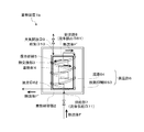
- FIG. 1 is a schematic explanatory diagram showing the structure of a heat storage device 1a according to the first embodiment of the present invention.
- the heat storage device 1 a includes a heat storage material 4, a holding member 5 that holds the heat storage material 4, and a heat storage material container 2 that houses the heat storage material 4 and the holding member 5.
- a heat exchanging section 3 through which a heat fluid F from the outside that exchanges heat with the air passes is provided.
- the heat storage material container 2 is provided with a fluid supply port 71 as a supply unit 7 for supplying the thermal fluid F from the outside, and a fluid discharge port 81 as a discharge unit 8 for discharging the heat fluid F ′ after heat exchange to the outside. Is provided.
- a heat retaining unit 6 is provided outside the heat storage material container 2 to keep the heat storage material container 2 warm by the heat fluid F ′ after the heat exchange discharged from the discharge unit 8.
- each configuration will be described in detail.
- the heat storage material 4 is a chemical substance that is separated into a heat storage product and a generated fluid during heating, and releases heat by the reverse reaction.
- a heat storage product and a production fluid calcium oxide (CaO) and water vapor (H 2 O), calcium chloride (CaCl 2 ) and water vapor (H 2 O), calcium bromide (CaBr 2 ) and water vapor (H 2 O) ), Calcium iodide (CaI 2 ) and water vapor (H 2 O), magnesium oxide (MgO) and water vapor (H 2 O), magnesium chloride (MgCl 2 ) and water vapor (H 2 O), zinc chloride (ZnCl 2 ) And water vapor (H 2 O), strontium chloride (SrCl 2 ) and ammonia (NH 3 ), strontium bromide (SrBr 2 ) and ammonia (NH 3 ), calcium oxide (CaO) and carbon dioxide (CO 2 ), magnesium oxide (CaO) and carbon dioxide
- the heat storage material 4 preferably uses water vapor as a product fluid and a reaction fluid.
- the heat storage device in the present invention is a configuration that particularly exhibits the effect at the time of chemical heat storage at high temperature
- the heat storage material 4 in the present invention as a heat storage product and a product fluid capable of chemical heat storage at high temperature, It is preferable to use a combination of calcium oxide and water vapor (400 to 500 degrees) or a combination of magnesium oxide and water vapor (300 to 400 degrees).
- the structure and shape of the heat storage material 4 in the present invention are not particularly limited, and may be a powder, a molded body obtained by molding the powder, or a material in which the heat storage material 4 is supported on a porous body.
- the structure of the holding member 5 that holds the heat storage material 4 is a structure that holds the heat storage material 4 in the heat storage material container 2 and enables heat exchange between the heat storage material 4 and the heat exchange unit 3.
- FIG. 1 illustrates a structure in which the heat storage material 4 is stored in one container, but is not limited to this. For example, a configuration in which a plurality of box-shaped containers or tray-shaped containers in which the heat storage material 4 is stored is stacked. It is good.
- the material of the holding member 5 is not particularly limited as long as it can withstand high temperature processing.
- the heat storage material container 2 is a structure for accommodating the heat storage material 4 and is made of a sealable structure.
- a heat exchange part 3 through which a heat fluid F for transferring heat between the heat storage material 4 housed inside and the outside passes, and a heat fluid F from the outside is supplied to the heat exchange part 3.
- It has a fluid supply port 71 for supply and a fluid discharge port 81 for discharging the fluid F ′ after heat exchange from the heat exchange unit 3.
- the heat storage material container 2 has pressure resistance.
- the inside of the heat storage material container 2 is depressurized, and it is possible to facilitate the movement of the reaction fluid generated from the heat storage material 4 and the reaction fluid that reacts with the heat storage product, and to enhance the heat storage effect of the heat storage material container 2.
- the shape of the heat storage material container 2 is not particularly limited, and examples thereof include a box shape and a cylindrical shape.
- the heat exchanging unit 3 may have any shape as long as it can transfer heat between the heat storage material 4 housed inside the holding member 5 and the heat fluid F from the outside. It is constituted by a heat exchange tube installed meandering inside, a double cylindrical inner cylinder portion with respect to the holding member 5 or the like.
- the fluid supply port 71 and the fluid discharge port 81 may be arranged on different surfaces with respect to the heat storage material container 2, or may be arranged on the same surface.
- a fluid supply port 71 is provided in the lower part of the heat storage material container 2
- a fluid discharge port 81 is provided in the upper part of the heat storage material container 2. It is good also as a structure to provide. Moreover, it is good also as a structure which provides the fluid supply port 71 and the fluid discharge port 81 in the same surface of the thermal storage material container 2, and performs supply and discharge
- the heat storage material container 2 has an air opening 9 for releasing the generated fluid generated from the heat storage material 4 during heat storage to the atmosphere, and an air supply port 10 for supplying a reaction fluid that reacts with the heat storage product during heat dissipation. It has. Moreover, as shown in FIG. 1, the air release port 9 and the air supply port 10 penetrate the heat retaining section 6 described later and communicate with the atmosphere (external environment). In the heat storage device 1a of the first embodiment, the air opening 9 and the air supply port 10 use the same vent, but may be provided at different positions.
- the air opening 9 is configured to discharge the generated fluid generated from the heat storage material 4 to the outside of the heat storage material container 2 during heat storage, and is a liquid receiving tank (not shown) that aggregates and collects the generated fluid. ) May be provided. Since the generated fluid is released to the outside by having the air opening 9, there is no need to provide a liquid receiving tank for aggregating and collecting the generated fluid, and the generated fluid is transferred from the heat supply area to the heat demand area. There is no need to transport. Therefore, there are advantages such as downsizing of the apparatus and reduction in transportation cost.
- the air supply port 10 is configured to be opened at the time of heat dissipation and supply the reaction fluid to the heat storage material container 2, and is connected to a supply unit (not shown) for supplying the reaction fluid at the time of heat dissipation.
- the heat fluid F may be of a temperature that can supply heat to the heat storage material 4, and is preferably a fluid such as gas or liquid. Furthermore, it is particularly preferable to use a gas from the viewpoint of excellent handleability.
- the heat retaining unit 6 is configured to keep the heat storage material container 2 warm by using the thermal fluid F ′ discharged from the heat storage material container 2, and is provided so as to cover the periphery of the heat storage material container 2. As shown in FIG. 1, the heat retaining section 6 is connected to the discharge section 8 of the heat storage material container 2, and is a discharge member made of a jacket-like member having a space for introducing the thermal fluid F ′ discharged from the discharge section 8. A thermal fluid introduction container 61 is provided, and a discharge port 62 for discharging the thermal fluid F ′ to the outside is provided.
- the temperature of the thermal fluid F ′ discharged from the heat storage material container 2 is lower than the temperature of the heat fluid F before heat exchange, but is higher than the temperature of the heat storage material 4 and further the external environment (atmosphere) of the heat storage device 1a. It is at a sufficiently high temperature. Therefore, by introducing the thermal fluid F ′ into the heat retaining unit 6, the temperature inside the heat retaining unit 6 can be made higher than that in the external environment. Thereby, heat release from the heat storage material container 2 to the external environment such as the atmosphere is suppressed, and the heat storage material 4 in the heat storage material container 2 can be maintained at a high temperature without using an additional heat source. In particular, chemical heat storage can contribute to an improvement in reaction rate.
- the shape of the exhaust heat fluid introduction container 61 is not particularly limited as long as it has a space for introducing the thermal fluid F ′ discharged from the heat storage material container 2.
- it may be a box shape or a cylindrical shape, and may be adapted to the shape of the heat storage material container 2. Thereby, it becomes possible to use a comparatively simple structure as what has the function of the heat retention part 6.
- FIG. 1 A block shape or a cylindrical shape, and may be adapted to the shape of the heat storage material container 2.
- the position of the discharge port 62 provided in the heat retaining unit 6 is not particularly limited. For example, it may be provided on the side surface or the bottom surface of the exhaust heat fluid introduction container 61 or may be provided on the same surface as the fluid supply port 71 of the heat storage material container 2. In addition, when the discharge port 62 is provided on the same surface as the fluid supply port 71 to the heat storage material container 2, the structure of the heat storage device 1a as a whole becomes compact, so the options for the installation location of the heat storage device 1a can be expanded. It becomes. Further, when the discharge port 62 is provided at the lower side or bottom of the side surface of the exhaust heat fluid introduction container 61, when the liquid is used as the heat fluid F, the heat fluid F ′ can be easily discharged from the heat storage device 1a. .
- a heat radiation suppressing material 63 such as a heat insulating material or a heat reflecting member may be provided on the side surface of the exhaust heat fluid introducing container 61. Further, the heat radiation suppressing material 63 may be provided on either the inner side surface or the outer side surface of the exhaust heat fluid introduction container 61. Thereby, it is possible to further suppress heat dissipation from the heat storage device 1a to increase heat storage efficiency.
- a heat insulating material if it consists of a material which suppresses releasing the heat
- the heat storage apparatus 1a whole can be covered with a heat insulating material by providing in the outer surface of the exhaust heat fluid introduction
- the heat reflecting member is not particularly limited as long as it is made of a material that can reflect the radiant heat emitted from the heat storage material container 2 and the heat in the exhaust heat fluid introduction container 61. Examples of such materials include aluminum, iron, copper, brass, silver, gold, platinum, nickel, stainless steel, chromium, tungsten, and the like. Non-metals include quartz glass, alumina ceramics, magnesia ceramics, refractory bricks and the like.
- released from the thermal storage material container 2 can be performed efficiently by providing in the inner surface of the exhaust heat fluid introduction
- the heat fluid F ′ after heat exchange with the heat storage material 4 is introduced into the heat retaining portion 6 provided outside the heat storage material container 2 in which the heat storage material 4 is stored.
- the temperature in the heat retaining unit 6 can be increased without requiring another heat source.
- T0 the external environment temperature such as the atmosphere
- T1 the temperature of the heat storage material 4 in the heat storage material container 2
- T2 the temperature in the heat retaining unit 6
- T0 ⁇ T2 ⁇ T1 is established.
- the heat storage efficiency to the heat storage material 4 by F can be maintained, and the temperature drop of the heat storage material 4 can be suppressed.
- the temperature of the thermal fluid F ′ after heat exchange also exceeds several hundred degrees, so the temperature T2 of the heat retaining unit 6 is also 100. It becomes a high temperature exceeding the degree. Therefore, T0 ⁇ T2 ⁇ T1.
- the temperature difference between the heat storage material container 2 housing the heat storage material 4 and the heat retaining section 6 provided outside the heat storage material container 2 is larger than the temperature difference between the heat storage material container 2 and the external environment such as the atmosphere. Since it becomes considerably small, it becomes possible to suppress the temperature drop of the heat storage material container 2 and to greatly suppress the heat loss of the heat storage material 4.
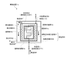
- FIG. 2 is a schematic explanatory view showing the structure of the heat storage device 1b according to the second embodiment of the present invention.
- This heat storage device 1b is the heat storage device 1a of the first embodiment, in which the heat retaining section 6 is a flow path 64 surrounding the heat storage material container 2.
- the flow path 64 is directly connected to the discharge unit 8, and the heat fluid F ′ after heat exchange is introduced into the flow path 64.
- description is abbreviate
- the heat storage device 1b since the heat fluid F ′ after heat exchange continuously passes through the heat retaining section 6, the heat energy of the heat fluid F ′ is efficiently maintained at the temperature of the heat storage material container 2. It becomes possible to use it.
- the flow path 64 surrounds the heat storage material container 2 in a spiral shape.
- a configuration in which a plurality of linear flow paths are provided from the upper part to the lower part of the heat storage material container 2 may be used.
- the heat retaining section 6 in the present embodiment is preferably configured as a flow path that spirally surrounds the heat storage material container 2 as shown in FIG.
- FIG. 3 is a schematic explanatory view showing the structure of the heat storage device 1c according to the third embodiment of the present invention.
- This heat storage device 1c includes a plurality of heat storage material containers in the heat storage device 1a of the first embodiment, and stores the heat storage material in each of them. At this time, it is assumed that the heat retaining section 6 is provided around the outermost heat storage material container.
- a plurality of heat storage material containers 2a and 2b are provided, and the heat storage materials 4a and 4b are respectively stored therein.
- thermoelectric layer composed of a plurality of temperature zones is formed between the innermost heat storage material container and the external environment such as the atmosphere, and heat loss due to heat radiation from the heat storage material in the heat storage material container is reduced. Further suppression is possible.
- the heat storage material container 2b is provided outside the heat storage material container 2a, and the heat storage material container 2b is provided outside.
- the thing which provides the heat retention part 6 is mentioned.
- the heat storage material 4a stored in the heat storage material container 2a and the heat storage material 4b stored in the heat storage material container 2b may be made of the same material or different materials.
- the temperature at which each heat storage material can store heat is different.
- the heat storage material 4a arranged on the inner side in the heat storage device 1c is made of a material having a higher temperature capable of storing heat than the heat storage material 4b. Thereby, it becomes possible to maintain the temperature of the heat storage material 4a at the innermost side of the heat storage device 1c high and to significantly suppress heat loss until reaching the external environment of the heat storage device 1c.
- the embodiment described above shows an example of a heat storage device.
- the heat storage device according to the present invention is not limited to the above-described embodiment, and the heat storage device according to the above-described embodiment may be modified without changing the gist described in the claims.
- a heat radiation suppressing material such as a heat insulating material or a heat reflecting member may be provided not only in the heat retaining unit but also in the heat storage material container.
- a plurality of heat retaining units may be provided, and the temperature of the heat retaining unit may be lowered step by step.
- a plurality of temperature zone layers are formed between the heat storage material container and an external environment such as the atmosphere, and heat loss of the heat storage material in the heat storage material container can be suppressed.
- the heat storage device of the present invention is used to effectively use waste heat generated from factories, garbage incineration plants, and the like.
- the heat storage device of the present invention is stored in a heat supply area where waste heat is generated, and the heat storage device is used for transporting and radiating heat to a heat demand place where heat is required. It can also be used to store heat during the time when waste heat is generated and to dissipate heat during the time when heat is required, such as storing heat during the day and radiating at night. it can.
Landscapes
- Engineering & Computer Science (AREA)
- Physics & Mathematics (AREA)
- Thermal Sciences (AREA)
- Mechanical Engineering (AREA)
- General Engineering & Computer Science (AREA)
- Packages (AREA)
- Cooling Or The Like Of Electrical Apparatus (AREA)
Abstract
本発明の課題は、蓄熱装置から外部環境への放熱を抑制し、より蓄熱効率を向上させることが可能な蓄熱装置を提供することにある。 上記課題を解決するために、蓄熱材が収納される蓄熱材容器と、蓄熱材容器に対して熱流体を供給するための供給部と、蓄熱材容器から熱流体を排出するための排出部と、排出部と接続され、排出された熱流体によって蓄熱材容器を保温するための保温部とを備えた蓄熱装置を提供する。この蓄熱装置によれば、蓄熱材を収納した蓄熱材容器の外側に保温部を設け、保温部に熱交換後の熱流体を導入することで、追加の熱源を用いることなく、熱交換後の熱流体が有する熱エネルギーを用いて保温部の温度を上げることが可能となる。これにより、蓄熱材容器と大気等の外部環境の間に高温の層を設けることで、蓄熱材容器からの熱損失を大幅に抑制することが可能となる。
Description
本発明は、蓄熱装置に関する。特に、化学反応を利用して蓄熱を行う化学蓄熱装置に関する。
工場やごみ焼却場等においては、膨大な量の廃熱が発生するため、省エネルギー化や未利用エネルギーの有効活用の観点から、これらの廃熱を蓄熱して利用する蓄熱システムに関する研究開発が進められている。
例えば、特許文献1には、外部からの熱エネルギーを貯蔵する蓄熱材に蓄熱し、蓄熱した蓄熱材を保管又は熱エネルギーが必要な場所に移送して利用する化学蓄熱反応器が開示されている。特許文献1には、化学蓄熱の具体例として、400度を超える高温の廃熱を効率よく蓄熱するために、化学蓄熱材として水酸化カルシウム系蓄熱材を用いた系が記載されている。
このような蓄熱装置では、熱源から熱流体を介して蓄熱材に熱移動させ、蓄熱操作後、そのまま装置外へと熱放出される。しかしながら、蓄熱材を保持する容器から大気等への外部環境(常温部分)への熱放散による熱損失が起こる。特に、高温廃熱を蓄熱する場合、大気等への外部環境との温度差が大きいことから、熱放出による熱損失の影響が大きくなる。
そこで、本発明の課題は、蓄熱装置から外部環境への放熱を抑制し、より蓄熱効率を向上させることが可能な蓄熱装置を提供することにある。
上記の課題について鋭意検討した結果、蓄熱装置において、蓄熱操作を終えた熱流体を利用する保温部を設けることにより、蓄熱装置の蓄熱効率を向上させることができることを見出して、本発明を完成した。
すなわち、本発明は、以下の蓄熱装置である。
すなわち、本発明は、以下の蓄熱装置である。
上記課題を解決するための本発明の蓄熱装置は、蓄熱材に対して熱を蓄熱する蓄熱装置であって、蓄熱材が収納される蓄熱材容器と、蓄熱材容器に対して熱流体を供給するための供給部と、蓄熱材容器から熱流体を排出するための排出部と、排出部と接続され、排出された熱流体によって蓄熱材容器を保温するための保温部とを備えることを特徴とするものである。
この蓄熱装置によれば、蓄熱材を収納した蓄熱材容器の外側に保温部を設け、保温部に熱交換後の熱流体を導入することで、追加の熱源を用いることなく、熱交換後の熱流体が有する熱エネルギーを用いて保温部の温度を上げることが可能となる。これにより、蓄熱材容器と大気等の外部環境の間に高温の層を設けることで、蓄熱材容器からの熱損失を大幅に抑制することが可能となる。
更に、本発明の蓄熱装置の一実施態様としては、保温部は、蓄熱材容器の周囲を覆うジャケット状の部材であることを特徴とするものである。
この特徴によれば、比較的簡易な構造で蓄熱材容器からの熱損失を大幅に抑制することが可能となる。
この特徴によれば、比較的簡易な構造で蓄熱材容器からの熱損失を大幅に抑制することが可能となる。
更に、本発明の蓄熱装置の一実施態様としては、保温部は、蓄熱材容器の周囲を囲む流路であることを特徴とするものである。
この特徴によれば、熱流体を連続的に蓄熱材容器の周囲に導入することで、蓄熱材容器の温度維持効果を向上させ、蓄熱材容器からの熱損失を大幅に抑制することが可能となる。
この特徴によれば、熱流体を連続的に蓄熱材容器の周囲に導入することで、蓄熱材容器の温度維持効果を向上させ、蓄熱材容器からの熱損失を大幅に抑制することが可能となる。
更に、本発明の蓄熱装置の一実施態様としては、保温部の温度は、蓄熱材の温度よりも低く、蓄熱装置の外部環境の温度よりも高く維持されることを特徴とするものである。
この特徴によれば、熱流体による蓄熱材への蓄熱効率を維持し、かつ蓄熱材の温度低下を抑制することができる。また、特に高温の蓄熱操作を行う際に、蓄熱材を収納する蓄熱材容器と保温部との温度差は、蓄熱材容器と大気等の外部環境との間の温度差よりもかなり小さくなることから、蓄熱材容器の温度低下を抑え、蓄熱材の熱損失を大幅に抑制することが可能となる。
この特徴によれば、熱流体による蓄熱材への蓄熱効率を維持し、かつ蓄熱材の温度低下を抑制することができる。また、特に高温の蓄熱操作を行う際に、蓄熱材を収納する蓄熱材容器と保温部との温度差は、蓄熱材容器と大気等の外部環境との間の温度差よりもかなり小さくなることから、蓄熱材容器の温度低下を抑え、蓄熱材の熱損失を大幅に抑制することが可能となる。
本発明によると、蓄熱装置から外部環境への放熱を抑制し、より蓄熱効率を向上させることが可能な蓄熱装置を提供することができる。
以下、図面を参照しつつ本発明に係る好適な実施態様について詳細に説明する。
なお、実施態様に記載する蓄熱装置については、本発明に係る蓄熱装置を説明するために例示したにすぎず、これに限定されるものではない。
なお、実施態様に記載する蓄熱装置については、本発明に係る蓄熱装置を説明するために例示したにすぎず、これに限定されるものではない。
本発明の蓄熱装置は、蓄熱材に対して熱を蓄熱する蓄熱装置に係るものである。このような蓄熱装置における蓄熱技術としては、物質の状態変化を伴わない温度差を利用した顕熱蓄熱、固体・液体・気体といった物質の相変化を利用した潜熱蓄熱、化学反応を利用した化学蓄熱が挙げられる。特に、物質の化学反応を利用した化学蓄熱は、顕熱蓄熱や潜熱蓄熱に比べて蓄熱密度が非常に大きく、化学反応前後の物質が安定であれば放熱ロスもほとんどなく、長期間の蓄熱において熱損失が生じないことが知られている。
なお、本実施態様における蓄熱装置としては化学蓄熱に係るものを例示しているが、これに限定されるものではなく、顕熱蓄熱や潜熱蓄熱に係るものであってもよい。
なお、本実施態様における蓄熱装置としては化学蓄熱に係るものを例示しているが、これに限定されるものではなく、顕熱蓄熱や潜熱蓄熱に係るものであってもよい。
[蓄熱装置]
本発明の蓄熱装置は、蓄熱時には、蓄熱材を加熱して蓄熱生成物と生成流体に分離し、放熱時には、前記蓄熱生成物と反応流体を反応させて前記蓄熱材を生成する化学蓄熱装置であり、工場やごみ焼却場等から発生する廃熱を蓄熱材に貯蔵して、熱を必要とする熱需要地まで輸送が可能な装置である。
本発明の蓄熱装置は、蓄熱時には、蓄熱材を加熱して蓄熱生成物と生成流体に分離し、放熱時には、前記蓄熱生成物と反応流体を反応させて前記蓄熱材を生成する化学蓄熱装置であり、工場やごみ焼却場等から発生する廃熱を蓄熱材に貯蔵して、熱を必要とする熱需要地まで輸送が可能な装置である。
本発明の蓄熱装置の構成としては、蓄熱材と、蓄熱材が収容される蓄熱材容器と、前記蓄熱材容器に対して熱流体を供給するための供給部と、前記蓄熱材容器から熱流体を排出するための排出部と、前記排出部と接続され、排出された熱流体によって前記蓄熱材容器を保温するための保温部を備えている。
〔第一の実施態様〕
図1は、本発明の第一の実施態様の蓄熱装置1aの構造を示す概略説明図である。この蓄熱装置1aは、蓄熱材4と、蓄熱材4を保持する保持部材5と、蓄熱材4及び保持部材5を収納する蓄熱材容器2を備え、蓄熱材容器2の内部には蓄熱材4と熱交換を行う外部からの熱流体Fが通過する熱交換部3が設けられている。また、蓄熱材容器2には、熱流体Fを外部から供給する供給部7として流体供給口71が設けられ、熱交換後の熱流体F′を外部に排出する排出部8として流体排出口81が設けられている。更に、蓄熱材容器2の外側には、排出部8から排出された熱交換後の熱流体F′によって蓄熱材容器2を保温する保温部6が配設されている。
以下、各構成について詳細に説明する。
図1は、本発明の第一の実施態様の蓄熱装置1aの構造を示す概略説明図である。この蓄熱装置1aは、蓄熱材4と、蓄熱材4を保持する保持部材5と、蓄熱材4及び保持部材5を収納する蓄熱材容器2を備え、蓄熱材容器2の内部には蓄熱材4と熱交換を行う外部からの熱流体Fが通過する熱交換部3が設けられている。また、蓄熱材容器2には、熱流体Fを外部から供給する供給部7として流体供給口71が設けられ、熱交換後の熱流体F′を外部に排出する排出部8として流体排出口81が設けられている。更に、蓄熱材容器2の外側には、排出部8から排出された熱交換後の熱流体F′によって蓄熱材容器2を保温する保温部6が配設されている。
以下、各構成について詳細に説明する。
(蓄熱材)
蓄熱材4とは、加熱時に蓄熱生成物と生成流体に分離され、また、この逆の反応により熱を放出する化学物質である。例えば、蓄熱生成物と生成流体として、酸化カルシウム(CaO)と水蒸気(H2O)、塩化カルシウム(CaCl2)と水蒸気(H2O)、臭化カルシウム(CaBr2)と水蒸気(H2O)、ヨウ化カルシウム(CaI2)と水蒸気(H2O)、酸化マグネシウム(MgO)と水蒸気(H2O)、塩化マグネシウム(MgCl2)と水蒸気(H2O)、塩化亜鉛(ZnCl2)と水蒸気(H2O)、塩化ストロンチウム(SrCl2)とアンモニア(NH3)、臭化ストロンチウム(SrBr2)とアンモニア(NH3)、酸化カルシウム(CaO)と二酸化炭素(CO2)、酸化マグネシウム(MgO)と二酸化炭素等(CO2)が挙げられる。取り扱いが容易であるという観点から、蓄熱材4は、生成流体及び反応流体として水蒸気を利用するものであることが好ましい。
また、本発明における蓄熱装置は、高温での化学蓄熱時に特に効果を発揮する構成であるため、本発明における蓄熱材4としては、高温での化学蓄熱が可能な蓄熱生成物と生成流体として、酸化カルシウムと水蒸気の組み合わせ(400~500度)や酸化マグネシウムと水蒸気の組み合わせ(300~400度)を用いることが好ましい。
蓄熱材4とは、加熱時に蓄熱生成物と生成流体に分離され、また、この逆の反応により熱を放出する化学物質である。例えば、蓄熱生成物と生成流体として、酸化カルシウム(CaO)と水蒸気(H2O)、塩化カルシウム(CaCl2)と水蒸気(H2O)、臭化カルシウム(CaBr2)と水蒸気(H2O)、ヨウ化カルシウム(CaI2)と水蒸気(H2O)、酸化マグネシウム(MgO)と水蒸気(H2O)、塩化マグネシウム(MgCl2)と水蒸気(H2O)、塩化亜鉛(ZnCl2)と水蒸気(H2O)、塩化ストロンチウム(SrCl2)とアンモニア(NH3)、臭化ストロンチウム(SrBr2)とアンモニア(NH3)、酸化カルシウム(CaO)と二酸化炭素(CO2)、酸化マグネシウム(MgO)と二酸化炭素等(CO2)が挙げられる。取り扱いが容易であるという観点から、蓄熱材4は、生成流体及び反応流体として水蒸気を利用するものであることが好ましい。
また、本発明における蓄熱装置は、高温での化学蓄熱時に特に効果を発揮する構成であるため、本発明における蓄熱材4としては、高温での化学蓄熱が可能な蓄熱生成物と生成流体として、酸化カルシウムと水蒸気の組み合わせ(400~500度)や酸化マグネシウムと水蒸気の組み合わせ(300~400度)を用いることが好ましい。
本発明における蓄熱材4の構造及び形状については、特に限定するものではなく、粉体、粉体を成形した成形体、または蓄熱材4を多孔質体に担持させたものであってもよい。
蓄熱材4を保持する保持部材5の構造は、蓄熱材容器2内で蓄熱材4を保持し、かつ蓄熱材4と熱交換部3との間で熱交換を可能とする構造のものであれば、特に限定されない。図1には、1つの容器内に蓄熱材4を収納した構造を例示したが、これに限定されるものではなく、例えば、蓄熱材4を収納した箱状容器やトレイ状容器を複数積み重ねる構成としてもよい。
また、保持部材5の材質は、高温処理に耐えられるものであれば、特に限定されない。
また、保持部材5の材質は、高温処理に耐えられるものであれば、特に限定されない。
(蓄熱材容器)
蓄熱材容器2は、蓄熱材4を収納するための構成であり、密閉可能な構造物からなる。蓄熱材容器2には、内部に収納された蓄熱材4と外部との熱の伝達を行うための熱流体Fが通過する熱交換部3、該熱交換部3に外部からの熱流体Fを供給するための流体供給口71、熱交換部3から熱交換後の流体F′を排出するための流体排出口81を有する。なお、蓄熱材容器2は、耐圧性を有することが好ましい。これにより、蓄熱材容器2内を減圧し、蓄熱材4から発生する生成流体や蓄熱生成物と反応する反応流体の移動を容易にするとともに、蓄熱材容器2の蓄熱効果を高めることが可能となる。
また、蓄熱材容器2の形状は、特に限定されず、例えば箱状や筒型とすることが挙げられる。
蓄熱材容器2は、蓄熱材4を収納するための構成であり、密閉可能な構造物からなる。蓄熱材容器2には、内部に収納された蓄熱材4と外部との熱の伝達を行うための熱流体Fが通過する熱交換部3、該熱交換部3に外部からの熱流体Fを供給するための流体供給口71、熱交換部3から熱交換後の流体F′を排出するための流体排出口81を有する。なお、蓄熱材容器2は、耐圧性を有することが好ましい。これにより、蓄熱材容器2内を減圧し、蓄熱材4から発生する生成流体や蓄熱生成物と反応する反応流体の移動を容易にするとともに、蓄熱材容器2の蓄熱効果を高めることが可能となる。
また、蓄熱材容器2の形状は、特に限定されず、例えば箱状や筒型とすることが挙げられる。
熱交換部3は、保持部材5内部に収納された蓄熱材4と外部からの熱流体Fとの熱の伝達を行うことができれば、どのような形状のものでもよく、例えば、保持部材5の内部に蛇行して設置された熱交換チューブや、保持部材5に対する2重円筒型の内筒部などにより構成される。
流体供給口71と流体排出口81は、それぞれ蓄熱材容器2に対して異なる面に配置してもよいし、同一面に配置してもよい。例えば、図1に示すように、蓄熱材容器2の中心軸に沿って、蓄熱材容器2の下方部には流体供給口71を設け、蓄熱材容器2の上方部には流体排出口81を設ける構成としてもよい。また、蓄熱材容器2の同一面に流体供給口71と流体排出口81を設ける構成とし、熱流体の供給、排出を1つの面で行うものとしてもよい。
また、蓄熱材容器2には、蓄熱時に蓄熱材4から発生した生成流体を大気に放出するための大気開放口9、放熱時に蓄熱生成物と反応する反応流体を供給するための給気口10を備えている。また、図1に示すように、大気開放口9と給気口10は、後述する保温部6を貫通し、大気(外部環境)に連通するものである。なお、第一の実施態様の蓄熱装置1aでは、大気開放口9と給気口10は同一の通気口を使用しているが、別の位置に設けてもよい。
大気開放口9は、蓄熱時に開放され、蓄熱材4から発生した生成流体を蓄熱材容器2の外部に排出するための構成であるが、生成流体を凝集して回収する受液槽(不図示)を設ける構成としてもよい。該大気開放口9を有することにより、生成流体は外部に放出されるため、生成流体を凝集して回収する受液槽を設ける必要がなく、また、生成流体を熱供給地から熱需要地に輸送する必要もない。そのため、装置のコンパクト化、輸送コストの低下等の利点がある。
給気口10は、放熱時に開放され、反応流体を蓄熱材容器2に供給するための構成であり、放熱時には、反応流体を供給するための供給部(不図示)と連結する。
熱流体Fとしては、蓄熱材4に熱を供給することができる温度のものであればよく、気体や液体等の流体が好ましい。更に取り扱い性に優れるという観点から、気体を使用することが特に好ましい。
(保温部)
保温部6は、蓄熱材容器2から排出された熱流体F′を用いて蓄熱材容器2を保温するための構成であり、蓄熱材容器2の周囲を覆うように設けられるものである。
図1に示すように、保温部6は、蓄熱材容器2の排出部8と接続し、排出部8から排出される熱流体F′を導入するための空間を有するジャケット状の部材からなる排熱流体導入容器61を備え、熱流体F′を外部に放出する放出口62を備えている。
保温部6は、蓄熱材容器2から排出された熱流体F′を用いて蓄熱材容器2を保温するための構成であり、蓄熱材容器2の周囲を覆うように設けられるものである。
図1に示すように、保温部6は、蓄熱材容器2の排出部8と接続し、排出部8から排出される熱流体F′を導入するための空間を有するジャケット状の部材からなる排熱流体導入容器61を備え、熱流体F′を外部に放出する放出口62を備えている。
排熱流体導入容器61と排出部8の接続手段は、特に限定されない。例えば、流体排出口81から排熱流体導入容器61内に熱流体F′を直接排出する構成としてもよく、流体排出口81にラインLを設け、排熱流体導入容器61内の任意の位置から熱流体F′が導入されるように構成するものであってもよい。
蓄熱材容器2から排出される熱流体F′の温度は、熱交換前の熱流体Fの温度よりも低くなるが、蓄熱材4の温度よりは高く、さらに蓄熱装置1aの外部環境(大気)より十分高い温度にある。したがって、この熱流体F′を保温部6に導入することで保温部6内を外部環境よりも高温とすることができる。これにより、蓄熱材容器2から大気等の外部環境への熱放出が抑制され、追加の熱源を用いることなく蓄熱材容器2内の蓄熱材4を高温に維持することが可能となる。特に、化学蓄熱においては反応速度の向上にも寄与することが可能となる。
排熱流体導入容器61の形状としては、蓄熱材容器2から排出された熱流体F′を導入する空間を有するものであればよく、特に制限されない。例えば、箱状や筒型であってもよく、蓄熱材容器2の形状に合わせたものとしてもよい。これにより、保温部6の機能を有するものとして、比較的簡易な構造を用いることが可能となる。
保温部6に設ける放出口62の位置は、特に限定されない。例えば、排熱流体導入容器61の側面又は底面に設けることとしてもよく、蓄熱材容器2の流体供給口71と同一面に設けることとしてもよい。なお、放出口62を蓄熱材容器2への流体供給口71と同一面に設けた場合、蓄熱装置1a全体としての構造がコンパクトになるため、蓄熱装置1aの設置箇所の選択肢を広げることが可能となる。また、放出口62を排熱流体導入容器61の側面下方部又は底部に設けた場合、熱流体Fとして液体を用いた際に、蓄熱装置1a内からの熱流体F′の排出が容易となる。
排熱流体導入容器61の側面に、断熱材又は熱反射部材のような放熱抑制材63を設けるものとしてもよい。また、放熱抑制材63は、排熱流体導入容器61の内側面あるいは外側面のいずれに設けてもよい。これにより、蓄熱装置1aから外部への放熱をより一層抑制し、蓄熱効率を高めることが可能となる。
なお、断熱材としては、排熱流体導入容器61内の熱を外部に放出させることを抑制する材質からなるものであれば、特に限定されない。例えば、発泡ポリエチレンや発泡スチロールなどの発泡樹脂、合成樹脂、無機材などが挙げられる。また、断熱材を用いる場合、排熱流体導入容器61の外側面に設けることで、蓄熱装置1a全体を断熱材で覆うことができ、蓄熱装置1a全体の蓄熱効率を向上させることができる。
一方、熱反射部材としては、蓄熱材容器2から放出される輻射熱や排熱流体導入容器61内の熱を反射可能な材質からなるものであれば、特に限定されない。このような材質は、例えば、金属としては、アルミニウム、鉄、銅、黄銅、銀、金、白金、ニッケル、ステンレス、クロム、タングステンなどが挙げられる。また、非金属としては、石英ガラス、アルミナセラミクス、マグネシアセラミクス、耐火レンガなどが挙げられる。また、熱反射部材を用いる場合、排熱流体導入容器61の内側面に設けることで蓄熱材容器2から放出される熱の反射を効率よく行うことができ、蓄熱材容器2の熱損失を大幅に抑制することが可能となる。
なお、断熱材としては、排熱流体導入容器61内の熱を外部に放出させることを抑制する材質からなるものであれば、特に限定されない。例えば、発泡ポリエチレンや発泡スチロールなどの発泡樹脂、合成樹脂、無機材などが挙げられる。また、断熱材を用いる場合、排熱流体導入容器61の外側面に設けることで、蓄熱装置1a全体を断熱材で覆うことができ、蓄熱装置1a全体の蓄熱効率を向上させることができる。
一方、熱反射部材としては、蓄熱材容器2から放出される輻射熱や排熱流体導入容器61内の熱を反射可能な材質からなるものであれば、特に限定されない。このような材質は、例えば、金属としては、アルミニウム、鉄、銅、黄銅、銀、金、白金、ニッケル、ステンレス、クロム、タングステンなどが挙げられる。また、非金属としては、石英ガラス、アルミナセラミクス、マグネシアセラミクス、耐火レンガなどが挙げられる。また、熱反射部材を用いる場合、排熱流体導入容器61の内側面に設けることで蓄熱材容器2から放出される熱の反射を効率よく行うことができ、蓄熱材容器2の熱損失を大幅に抑制することが可能となる。
以上のように、本実施態様における蓄熱装置1aにおいては、蓄熱材4を収納した蓄熱材容器2の外側に設けた保温部6に、蓄熱材4と熱交換後の熱流体F′を導入することで、他の熱源を必要とすることなく、保温部6内の温度を高めることができる。このとき、大気等の外部環境温度をT0、蓄熱材容器2内の蓄熱材4の温度をT1、保温部6内の温度をT2とした場合、T0<T2<T1が成り立つことで、熱流体Fによる蓄熱材4への蓄熱効率を維持し、かつ蓄熱材4の温度低下を抑制することができる。特に、化学蓄熱のように蓄熱材4の温度T1が数百度となるような高温である場合、熱交換後の熱流体F′の温度も数百度を超えるため、保温部6の温度T2も100度を超える高温となる。したがって、T0<<T2<T1となる。これにより、蓄熱材4を収納した蓄熱材容器2と、蓄熱材容器2外側に備えた保温部6との温度差は、蓄熱材容器2と大気等の外部環境との間の温度差よりもかなり小さくなることから、蓄熱材容器2の温度低下を抑え、蓄熱材4の熱損失を大幅に抑制することが可能となる。
[蓄熱装置のその他の態様]
以下に、蓄熱装置の別の態様について例示する。
〔第二の実施態様〕
図2は、本発明の第二の実施態様の蓄熱装置1bの構造を示す概略説明図である。
この蓄熱装置1bは、第一の実施態様の蓄熱装置1aにおいて、保温部6を蓄熱材容器2の周囲を囲む流路64としたものである。ここで、流路64は排出部8と直接接続されており、流路64内に熱交換後の熱流体F′が導入される。なお、本実施態様における蓄熱装置1bの構成のうち、第一の実施態様における蓄熱装置1aの構造と同じものについては説明を省略する。
この蓄熱装置1bによれば、保温部6内を熱交換後の熱流体F′が連続的に通過していくため、熱流体F′が有する熱エネルギーを効率的に蓄熱材容器2の温度維持に利用することが可能となる。
以下に、蓄熱装置の別の態様について例示する。
〔第二の実施態様〕
図2は、本発明の第二の実施態様の蓄熱装置1bの構造を示す概略説明図である。
この蓄熱装置1bは、第一の実施態様の蓄熱装置1aにおいて、保温部6を蓄熱材容器2の周囲を囲む流路64としたものである。ここで、流路64は排出部8と直接接続されており、流路64内に熱交換後の熱流体F′が導入される。なお、本実施態様における蓄熱装置1bの構成のうち、第一の実施態様における蓄熱装置1aの構造と同じものについては説明を省略する。
この蓄熱装置1bによれば、保温部6内を熱交換後の熱流体F′が連続的に通過していくため、熱流体F′が有する熱エネルギーを効率的に蓄熱材容器2の温度維持に利用することが可能となる。
第二の実施態様の蓄熱装置1bにおける保温部6としての流路64の具体的な構成の一例として、図2に示すように、蓄熱材容器2の周囲を螺旋状に囲む流路とする構成や、蓄熱材容器2の上方部から下方部に向けて直線状の流路を複数設ける構成などが挙げられる。
特に、本実施態様における保温部6としては、図2に示すような蓄熱材容器2の周囲を螺旋状に囲む流路とする構成とすることが好ましい。この構成とすることで、蓄熱材容器2と保温部6との接触面が広くなるため、保温部6による温度維持効果を高めることで、蓄熱材容器2内の蓄熱材4からの熱損失をより一層抑制することが可能となる。
特に、本実施態様における保温部6としては、図2に示すような蓄熱材容器2の周囲を螺旋状に囲む流路とする構成とすることが好ましい。この構成とすることで、蓄熱材容器2と保温部6との接触面が広くなるため、保温部6による温度維持効果を高めることで、蓄熱材容器2内の蓄熱材4からの熱損失をより一層抑制することが可能となる。
〔第三の実施態様〕
図3は、本発明の第三の実施態様の蓄熱装置1cの構造を示す概略説明図である。
この蓄熱装置1cは、第一の実施態様の蓄熱装置1aにおいて、複数の蓄熱材容器を備え、それぞれに蓄熱材を収納するものである。また、このとき、最も外側にある蓄熱材容器の周囲に保温部6を設けるものとする。図3には、本実施態様における蓄熱装置1cの一例として、複数の蓄熱材容器2a、2bを備え、それぞれに蓄熱材4a、4bを収納するものを示している。なお、本実施態様における蓄熱装置1cの構成のうち、第一の実施態様における蓄熱装置1aの構造と同じものについては説明を省略する。
この蓄熱装置1cによれば、最も内側にある蓄熱材容器と大気等の外部環境との間に複数の温度帯からなる層が形成され、蓄熱材容器内の蓄熱材からの放熱による熱損失をより一層抑制することが可能となる。
図3は、本発明の第三の実施態様の蓄熱装置1cの構造を示す概略説明図である。
この蓄熱装置1cは、第一の実施態様の蓄熱装置1aにおいて、複数の蓄熱材容器を備え、それぞれに蓄熱材を収納するものである。また、このとき、最も外側にある蓄熱材容器の周囲に保温部6を設けるものとする。図3には、本実施態様における蓄熱装置1cの一例として、複数の蓄熱材容器2a、2bを備え、それぞれに蓄熱材4a、4bを収納するものを示している。なお、本実施態様における蓄熱装置1cの構成のうち、第一の実施態様における蓄熱装置1aの構造と同じものについては説明を省略する。
この蓄熱装置1cによれば、最も内側にある蓄熱材容器と大気等の外部環境との間に複数の温度帯からなる層が形成され、蓄熱材容器内の蓄熱材からの放熱による熱損失をより一層抑制することが可能となる。
第三の実施態様における蓄熱装置1cにおける蓄熱材容器の具体的構造の例としては、図3に示すように、蓄熱材容器2aの外側に蓄熱材容器2bを設け、蓄熱材容器2bの外側に保温部6を設けるものが挙げられる。また、蓄熱材容器2a内に収納された蓄熱材4aと蓄熱材容器2b内に収納された蓄熱材4bは、同一材質からなるものであってもよく、異なる材質からなるものであってもよいが、それぞれの蓄熱材の蓄熱可能な温度が異なるものとすることが好ましい。このとき、蓄熱装置1cにおいてより内側に配されている蓄熱材4aのほうが蓄熱材4bよりも蓄熱可能な温度が高い材質からなることが好ましい。これにより、蓄熱装置1cの最内側にある蓄熱材4aの温度を高く維持し、かつ蓄熱装置1cの外部環境に至るまでの熱損失を大幅に抑制することが可能となる。
なお、上述した実施態様は蓄熱装置の一例を示すものである。本発明に係る蓄熱装置は、上述した実施態様に限られるものではなく、請求項に記載した要旨を変更しない範囲で、上述した実施態様に係る蓄熱装置を変形してもよい。
例えば、本実施態様における蓄熱装置において、保温部だけではなく、蓄熱材容器内においても、断熱材や熱反射部材などの放熱抑制材を設けることとしてもよい。これにより、蓄熱材容器自体の熱損失を抑制することで、保温部による温度維持効果をより一層高めることができ、蓄熱装置全体としての熱損失を大幅に抑制することが可能となる。
また、例えば、本実施態様における蓄熱装置において、複数の保温部を設け、段階的に保温部の温度を下げていくような構成とするものであってもよい。これにより、蓄熱材容器と大気等の外部環境との間に複数の温度帯の層を形成し、蓄熱材容器内の蓄熱材の熱損失を抑制することが可能となる。
本発明の蓄熱装置は、工場やごみ焼却場等から発生する廃熱の有効利用することに用いられる。例えば、廃熱が発生する熱供給地において本発明の蓄熱装置を蓄熱し、熱が必要な熱需要地に蓄熱装置を輸送して放熱することに利用する。また、昼に蓄熱して、夜に放熱するというように、同一の設置場所において、廃熱が発生する時間帯に蓄熱して、熱が要求される時間帯に放熱することに利用することもできる。
1a,1b,1c…蓄熱装置、2,2a,2b…蓄熱材容器、3…熱交換部、4,4a,4b…蓄熱材、5…保持部材、6…保温部、61…排熱流体導入容器、62…放出口、63…放熱抑制材、64…流路、7…供給部、71…流体供給口、8…排出部、81…流体排出口、9…大気開放口、10…給気口、F…熱流体、F′…熱交換後の熱流体、L…ライン
Claims (4)
- 蓄熱材に対して熱を蓄熱する蓄熱装置であって、
蓄熱材が収納される蓄熱材容器と、
前記蓄熱材容器に対して熱流体を供給するための供給部と、
前記蓄熱材容器から熱流体を排出するための排出部と、
前記排出部と接続され、排出された熱流体によって前記蓄熱材容器を保温するための保温部と、を備えることを特徴とする、蓄熱装置。 - 前記保温部は、前記蓄熱材容器の周囲を覆うジャケット状の部材であることを特徴とする、請求項1に記載の蓄熱装置。
- 前記保温部は、前記蓄熱材容器の周囲を囲む流路であることを特徴とする、請求項1に記載の蓄熱装置。
- 前記保温部の温度は、前記蓄熱材の温度よりも低く、蓄熱装置の外部環境の温度よりも高く維持されることを特徴とする、請求項1~3のいずれか一項に記載の蓄熱装置。
Applications Claiming Priority (2)
| Application Number | Priority Date | Filing Date | Title |
|---|---|---|---|
| JP2018-094926 | 2018-05-16 | ||
| JP2018094926A JP6992227B2 (ja) | 2018-05-16 | 2018-05-16 | 蓄熱装置 |
Publications (1)
| Publication Number | Publication Date |
|---|---|
| WO2019220705A1 true WO2019220705A1 (ja) | 2019-11-21 |
Family
ID=68540091
Family Applications (1)
| Application Number | Title | Priority Date | Filing Date |
|---|---|---|---|
| PCT/JP2019/004557 Ceased WO2019220705A1 (ja) | 2018-05-16 | 2019-02-08 | 蓄熱装置 |
Country Status (2)
| Country | Link |
|---|---|
| JP (1) | JP6992227B2 (ja) |
| WO (1) | WO2019220705A1 (ja) |
Families Citing this family (1)
| Publication number | Priority date | Publication date | Assignee | Title |
|---|---|---|---|---|
| JP2023135059A (ja) * | 2022-03-15 | 2023-09-28 | 日新電機株式会社 | 蓄熱器 |
Citations (3)
| Publication number | Priority date | Publication date | Assignee | Title |
|---|---|---|---|---|
| JP2017219234A (ja) * | 2016-06-06 | 2017-12-14 | 古河電気工業株式会社 | 蓄熱容器及び蓄熱容器を備えた蓄熱装置 |
| WO2018051951A1 (ja) * | 2016-09-13 | 2018-03-22 | 住友重機械工業株式会社 | 蓄熱装置、放熱システム及びその使用方法 |
| JP2018105602A (ja) * | 2016-12-28 | 2018-07-05 | 日本ペイントホールディングス株式会社 | 蓄放熱装置 |
-
2018
- 2018-05-16 JP JP2018094926A patent/JP6992227B2/ja active Active
-
2019
- 2019-02-08 WO PCT/JP2019/004557 patent/WO2019220705A1/ja not_active Ceased
Patent Citations (3)
| Publication number | Priority date | Publication date | Assignee | Title |
|---|---|---|---|---|
| JP2017219234A (ja) * | 2016-06-06 | 2017-12-14 | 古河電気工業株式会社 | 蓄熱容器及び蓄熱容器を備えた蓄熱装置 |
| WO2018051951A1 (ja) * | 2016-09-13 | 2018-03-22 | 住友重機械工業株式会社 | 蓄熱装置、放熱システム及びその使用方法 |
| JP2018105602A (ja) * | 2016-12-28 | 2018-07-05 | 日本ペイントホールディングス株式会社 | 蓄放熱装置 |
Also Published As
| Publication number | Publication date |
|---|---|
| JP6992227B2 (ja) | 2022-01-13 |
| JP2019199993A (ja) | 2019-11-21 |
Similar Documents
| Publication | Publication Date | Title |
|---|---|---|
| JP7682076B2 (ja) | 化学蓄熱装置 | |
| US7721750B2 (en) | Modified heat pipe for activation of a pressure relief device | |
| JP6647223B2 (ja) | 蓄熱容器及び蓄熱容器を備えた蓄熱装置 | |
| JPH03294763A (ja) | 冷却器 | |
| US10451323B2 (en) | Chemical heat pump | |
| JP6992227B2 (ja) | 蓄熱装置 | |
| JP2016008744A (ja) | 可逆的反応により蓄熱と放熱を繰り返す化学蓄熱体を用いる熱輸送システム | |
| JP7069648B2 (ja) | 熱交換型反応器 | |
| JP2016118315A (ja) | 化学蓄熱反応器及びこれを利用した熱輸送システム | |
| CN102753907B (zh) | 具有集成的化学热泵的太阳能板 | |
| GB2513990A (en) | Device for thermally insulating one or more elements of a subsea installation from ambient cold sea water | |
| JP6215048B2 (ja) | 蓄熱管理システム | |
| JP6674378B2 (ja) | 蓄熱材を収容する容器 | |
| CN118575052A (zh) | 筒式化学蓄热反应器、筒式化学蓄热反应器连结体、绝热件、换热配管连结件及化学蓄热方法 | |
| CN115031559A (zh) | 化学蓄热装置、化学蓄热材料的容纳容器及配置方法 | |
| JP7490341B2 (ja) | 化学蓄熱装置、及び化学蓄熱材の蓄熱方法 | |
| JP2020153614A (ja) | 蓄熱装置、カートリッジ、カートリッジの保管方法 | |
| JP5041356B2 (ja) | 耐火容器の蓋体および耐火容器 | |
| JP7797470B2 (ja) | 化学蓄熱反応器 | |
| KR200246702Y1 (ko) | 수소저장합금 수소저장탱크 | |
| JPH04272458A (ja) | 熱電併給システム | |
| JPH0655065U (ja) | 蓄熱器 | |
| JP2017219234A (ja) | 蓄熱容器及び蓄熱容器を備えた蓄熱装置 | |
| HK40112417A (zh) | 一种用於增强温跃层火用的方法 | |
| WO2021246429A1 (ja) | 蓄熱体カートリッジおよび蓄熱器 |
Legal Events
| Date | Code | Title | Description |
|---|---|---|---|
| 121 | Ep: the epo has been informed by wipo that ep was designated in this application |
Ref document number: 19803093 Country of ref document: EP Kind code of ref document: A1 |
|
| NENP | Non-entry into the national phase |
Ref country code: DE |
|
| 122 | Ep: pct application non-entry in european phase |
Ref document number: 19803093 Country of ref document: EP Kind code of ref document: A1 |