WO2019220558A1 - ナビゲーション装置およびナビゲーション方法 - Google Patents
ナビゲーション装置およびナビゲーション方法 Download PDFInfo
- Publication number
- WO2019220558A1 WO2019220558A1 PCT/JP2018/018904 JP2018018904W WO2019220558A1 WO 2019220558 A1 WO2019220558 A1 WO 2019220558A1 JP 2018018904 W JP2018018904 W JP 2018018904W WO 2019220558 A1 WO2019220558 A1 WO 2019220558A1
- Authority
- WO
- WIPO (PCT)
- Prior art keywords
- altitude
- route
- destination
- current position
- difference
- Prior art date
- Legal status (The legal status is an assumption and is not a legal conclusion. Google has not performed a legal analysis and makes no representation as to the accuracy of the status listed.)
- Ceased
Links
Images













Classifications
-
- G—PHYSICS
- G01—MEASURING; TESTING
- G01C—MEASURING DISTANCES, LEVELS OR BEARINGS; SURVEYING; NAVIGATION; GYROSCOPIC INSTRUMENTS; PHOTOGRAMMETRY OR VIDEOGRAMMETRY
- G01C21/00—Navigation; Navigational instruments not provided for in groups G01C1/00 - G01C19/00
- G01C21/26—Navigation; Navigational instruments not provided for in groups G01C1/00 - G01C19/00 specially adapted for navigation in a road network
Definitions
- the present invention relates to a navigation apparatus and a navigation method for guiding to a destination in consideration of an altitude difference between the destination and the current position or the final guidance location.
- the in-vehicle navigation device creates a route from the current position to the destination using position information acquired from GPS (Global Positioning System), and guides the destination according to the route.
- GPS Global Positioning System
- the altitude may be greatly different between the destination set by the user and the final guidance location.
- the final guide point refers to the final point where the vehicle is guided to reach.
- the distance on the map is short if the difference between the latitude and longitude between the final guide and the destination is small, but the distance traveled may actually be long because the stairs are actually up.
- the altitude difference between the final guide and the destination is large, it may be difficult for the driver to visually recognize the destination when arriving at the final guide.
- the difference in altitude between the final guidance point and the destination is large, it is useful for the driver to present the destination information in consideration of the difference in altitude to the driver.
- Patent Document 1 Conventionally, a technique for expressing an altitude difference by displaying a three-dimensional map has been disclosed (see, for example, Patent Document 1).
- Patent Document 1 does not clearly indicate the difference in altitude between the destination and the current position or the final guide. Therefore, when there is a large difference in altitude between the final guidance point and the destination, there is a problem that when the driver arrives at the final guidance point, it is difficult to visually recognize the destination. Moreover, in patent document 1, there exists a problem that the processing load for displaying a three-dimensional map is large.
- the present invention has been made to solve such a problem, and presents a navigation apparatus and navigation capable of presenting destination information in consideration of altitude difference and reducing the processing load related to the presenting. It aims to provide a method.
- a navigation device includes a current position acquisition unit that acquires the current position of a vehicle and its altitude, a map information acquisition unit that acquires map information including the position and its altitude, and a map.
- a route calculation unit that calculates a route from the current position acquired by the current position acquisition unit to a preset destination based on the map information acquired by the information acquisition unit, and a route guidance that guides the route calculated by the route calculation unit
- the route guidance unit is a first altitude difference that is an altitude difference between the altitude of the destination and the altitude of the current position, or a final guidance area where the destination altitude and the vehicle are finally guided to reach Based on the second altitude difference, which is the altitude difference from the altitude, information on the first altitude difference or the second altitude difference is displayed on a two-dimensional map.
- the navigation device is based on the current position acquisition unit that acquires the current position of the vehicle, the map information acquisition unit that acquires map information including the position and its altitude, and the map information acquired by the map information acquisition unit.
- a route calculation unit that calculates a route from the current position acquired by the current position acquisition unit to a preset destination, and a route guide unit that guides the route calculated by the route calculation unit.
- the navigation method acquires the current position of the vehicle and its altitude, acquires map information including the position and its altitude, and based on the acquired map information, the destination set in advance from the acquired current position
- the route to the vehicle is calculated, and the calculated route is guided and guided to the first altitude difference that is the altitude difference between the altitude of the destination and the altitude of the current position, or the altitude of the destination and the vehicle are finally determined. Displaying information on the first altitude difference or the second altitude difference on a two-dimensional map based on the second altitude difference, which is an altitude difference from the altitude of the final guidance location to be reached.
- the navigation device includes a current position acquisition unit that acquires the current position of the vehicle and its altitude, a map information acquisition unit that acquires map information including the position and its altitude, and a map acquired by the map information acquisition unit.
- a route calculation unit that calculates a route from the current position acquired by the current position acquisition unit to a preset destination based on the information, and a route guide unit that guides the route calculated by the route calculation unit; Is the first altitude difference that is the altitude difference between the altitude of the destination and the altitude of the current position, or the altitude difference between the altitude of the destination and the altitude of the final guidance location where the vehicle is finally guided to reach.
- a certain second height difference in order to display information on the first height difference or the second height difference on a two-dimensional map, information on the destination considering the height difference is presented, and processing related to the presentation Reduce load Theft is possible.
- the navigation device also includes a current position acquisition unit that acquires the current position of the vehicle, a map information acquisition unit that acquires map information including the position and its altitude, and the map information acquired by the map information acquisition unit.
- the route calculation unit includes a route calculation unit that calculates a route from the current position acquired by the position acquisition unit to a preset destination, and a route guidance unit that guides the route calculated by the route calculation unit.
- the navigation method acquires the current position of the vehicle and its altitude, acquires map information including the position and its altitude, and based on the acquired map information, routes from the acquired current position to a preset destination Is calculated, and the calculated route is guided to guide the first altitude difference that is the altitude difference between the altitude of the destination and the altitude of the current position, or the destination altitude and the vehicle finally reach Since the information about the first altitude difference or the second altitude difference is displayed on a two-dimensional map based on the second altitude difference, which is an altitude difference from the altitude of the final guidance location to be guided, It is possible to present information on the considered destination and reduce the processing load related to the presentation.
- FIG. 1 is a block diagram showing an example of a configuration of a navigation device 1 according to Embodiment 1 of the present invention.
- the navigation apparatus 1 shall be installed in the vehicle.
- the navigation device 1 includes a current position acquisition unit 2, a map information acquisition unit 3, a route calculation unit 4, and a route guidance unit 5.
- the current position acquisition unit 2 is connected to the GPS receiver 6.
- the map information acquisition unit 3 is connected to the map information database 7.
- the route guide unit 5 is connected to the display device 8 and the speaker 9.
- the current position acquisition unit 2 acquires the current position of the vehicle and its altitude from the GPS receiver 6.
- the GPS receiver 6 is installed in the vehicle and receives a GPS signal including the current position of the vehicle in which the GPS receiver 6 is installed and its altitude from a GPS satellite. Note that the current position acquisition unit 2 may obtain a more accurate current position of the vehicle based on the current position acquired from the GPS receiver 6 and the speed, moving distance, steering direction, and the like of the vehicle.
- the GPS receiver 6 may be included in the navigation device 1.
- the map information acquisition unit 3 acquires map information including the position and its altitude from the map information database 7.
- the map information database 7 is composed of a storage device such as a hard disk drive or a semiconductor memory, for example, and stores map information including at least an arbitrary position and its altitude.
- the map information database 7 may be installed on the vehicle or outside the vehicle.
- the map information database 7 may be included in the navigation device 1.
- the route calculation unit 4 calculates a route from the current position acquired by the current position acquisition unit 2 to a preset destination based on the map information acquired by the map information acquisition unit 3.
- a user such as a driver sets a destination using an input device (not shown).
- the route guidance unit 5 guides the route calculated by the route calculation unit 4. Specifically, the route guidance unit 5 displays the route on the display device 8 and outputs guidance related to the route from the speaker 9. In addition, the route guide unit 5 sets the first altitude difference that is the altitude difference between the altitude of the destination and the altitude of the current position, or the second altitude difference that is the altitude difference between the altitude of the destination and the altitude of the final guidance destination. Based on this, information on the first altitude difference or the second altitude difference is displayed on a two-dimensional map.
- Examples of the display device 8 include HUD (Head Up Display), CID (Central Information Display), and a display provided in the instrument panel.
- the display device 8 may be configured by any one of these, or may be configured by any combination.
- FIG. 2 is a block diagram illustrating an example of a hardware configuration of the navigation device 1.
- the functions of the current position acquisition unit 2, the map information acquisition unit 3, the route calculation unit 4, and the route guidance unit 5 in the navigation device 1 are realized by a processing circuit. That is, the navigation device 1 acquires the current position of the vehicle and its altitude, acquires map information including the position and its altitude, calculates a route, guides the route, and notifies information related to the altitude difference.
- the processing circuit is a processor 10 (also called a central processing unit, processing unit, arithmetic unit, microprocessor, microcomputer, DSP (Digital Signal Processor)) that executes a program stored in the memory 11.
- the functions of the current position acquisition unit 2, the map information acquisition unit 3, the route calculation unit 4, and the route guidance unit 5 in the navigation device 1 are realized by software, firmware, or a combination of software and firmware.
- Software or firmware is described as a program and stored in the memory 11.
- the processing circuit reads out and executes the program stored in the memory 11, thereby realizing the function of each unit. That is, the navigation device 1 notifies the current position of the vehicle and its altitude, the step of acquiring map information including the position and its altitude, the step of calculating the route, the step of guiding the route, and the information regarding the altitude difference.
- the memory is, for example, non-volatile or volatile such as RAM (Random Access Memory), ROM (Read Only Memory), flash memory, EPROM (Erasable Programmable Read Only Memory), EEPROM (Electrically Erasable Programmable Read Only Memory), etc. May be any semiconductor memory, magnetic disk, flexible disk, optical disk, compact disk, mini disk, DVD, or any other storage medium used in the future.
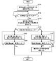
- FIG. 3 is a flowchart showing an example of the operation of the navigation device 1.
- step S101 the route calculation unit 4 calculates a route from the current position to the destination. Specifically, the route calculation unit 4 calculates the route from the current position acquired by the current position acquisition unit 2 to the destination set by the driver using the map information acquired by the map information acquisition unit 3. .
- step S102 the route calculation unit 4 determines whether or not the vehicle has approached the destination. Specifically, the route calculation unit 4 determines whether the vehicle has approached the destination based on the current position acquired by the current position acquisition unit 2 and the map information acquired by the map information acquisition unit 3. .
- that the vehicle has approached the destination means that the vehicle exists within 30 m from the destination, for example. At this time, the distance from the destination is not limited to 30 m, but is preferably in the vicinity of the destination.
- the process of step S102 is repeated until the vehicle approaches the destination. When the vehicle approaches the destination, the process proceeds to step S103.
- step S103 the route calculation unit 4 calculates an altitude difference between the altitude of the destination and the altitude of the current position. Specifically, the route calculation unit 4 calculates a difference between the altitude of the destination acquired by the map information acquisition unit 3 and the altitude of the current position acquired by the current position acquisition unit 2 as an altitude difference.
- step S104 the route calculation unit 4 determines whether the altitude difference calculated in step S103 is greater than or equal to a set value.
- the set value for the altitude difference may be 10 m, for example, but is not limited thereto. If the altitude difference is not greater than or equal to the set value, the process proceeds to step S105. On the other hand, if the altitude difference is greater than or equal to the set value, the process proceeds to step S107.
- step S105 the route guidance unit 5 displays the destination information not considering the altitude difference on the display device 8.
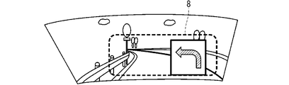
- the route guide unit 5 displays, for example, an arrow indicating the direction of the destination on the HUD.
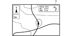
- the route guidance unit 5 displays, for example, an arrow indicating the direction of the destination on the CID.
- the arrow is displayed on the map.
- the route guidance part 5 may display the arrow which shows the direction of the destination on HUD and CID simultaneously.
- step S106 the route calculation unit 4 determines whether or not the vehicle has arrived at the final guide point. Since it is determined in step S104 that the altitude difference is not greater than or equal to the set value, the final guidance destination may coincide with the destination. That is, determining that the vehicle has arrived at the final guidance location in step S106 includes the arrival of the vehicle at the destination. If the vehicle has arrived at the final guide point, the process is terminated. On the other hand, if the vehicle has not arrived at the final guide point, the process returns to step S105.
- the route guidance unit 5 displays the destination information in consideration of the altitude difference on the display device 8. Specifically, when the display device 8 is a HUD as shown in FIG. 6, the route guidance unit 5 displays, for example, an arrow indicating the direction of the destination and an altitude difference on the HUD. When the display device 8 has a CID as shown in FIG. 7, the route guidance unit 5 displays, for example, an arrow indicating the direction of the destination and an altitude difference on the CID. In FIG. 7, the arrow is displayed on the map. In addition, the route guidance part 5 may display simultaneously the arrow which shows the direction of a destination, and an altitude difference on HUD and CID.
- step S108 the route calculation unit 4 determines whether or not the vehicle has arrived at the final guidance point. Since it is determined in step S104 that the altitude difference is greater than or equal to the set value, the final guidance destination and the destination do not match. That is, even if it is determined in step S106 that the vehicle has arrived at the final guidance location, the vehicle has not arrived at the destination. If the vehicle has arrived at the final guidance location, the process proceeds to step S109. On the other hand, if the vehicle has not arrived at the final guide point, the process returns to step S107.
- step S109 the route guidance unit 5 displays the final destination information on the display device 8.
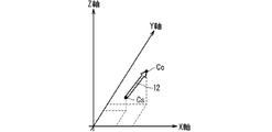
- the route guidance unit 5 displays an arrow object 12 as shown in FIG. 8 on the HUD that is the display device 8.
- the arrow object 12 corresponds to final destination information.
- an arrow object 12 is a straight line connecting the final guidance location Cs and the destination Ce, and indicates that the destination exists in the direction of the arrow.
- the inclination of the arrow object 12 with respect to the plane corresponds to the elevation angle when the destination Ce is viewed from the final guidance location Cs.
- the length of the arrow object 12 may be changed according to the distance between the final guidance location Cs and the destination Ce, such as increasing the length of the arrow object 12 as the distance between the final guidance location Cs and the destination Ce is longer.
- a numerical value indicating the distance between the final guidance location Cs and the destination Ce may be displayed. In this case, the combination of the arrow object 12 and the numerical value indicating the distance corresponds to final destination information.
- FIGS. 9 and 10 are diagrams illustrating an example of the arrow object 12.
- the arrow object 12 may be a curve.
- the arrow object 12 shown in FIG. 10 indicates that the altitude difference is larger than that of the arrow object 12 shown in FIG.
- the route guide unit 5 increases the (Z-axis direction distance
- the object 12 is displayed.
- a numerical object 13 as shown in FIG. 11 may be displayed together with the arrow object 12 shown in FIGS. In this case, the combination of the arrow object 12 and the numerical object 13 corresponds to final destination information.
- the numerical object 13 may be the distance between the final guidance location Cs and the destination Ce, or the altitude difference between the final guidance location Cs and the destination Ce.
- you may display the comparison object 14 as shown in FIG. 12 with the arrow object 12 shown in FIG.
- the combination of the arrow object 12 and the comparison object 14 corresponds to final destination information.
- the comparison object 14 is, for example, a person, but is not limited thereto.
- FIG. 13 is a diagram showing an example of final destination information, which is a deformation of a destination higher than the final guidance location Cs.
- the host vehicle object 15 is shown at the final guidance location Cs.
- a destination object 16 is shown at the destination Ce.
- a walking route object 17 is shown so as to connect the final guide point Cs and the destination Ce.
- a numerical object 13 indicating the distance or altitude difference between the final guidance location Cs and the destination Ce is shown together with the walking route object 17.
- FIGS. 14 to 16 are diagrams showing an example of final destination information displayed on the HUD that is the display device 8 when the destination cannot be seen from the final guidance point.
- HUD shall respond
- FIG. 14 shows a case where final destination information is not displayed. The driver sees the mountain 18-20 over the HUD.
- FIG. 15 shows a case where there is a destination on the mountain 18 and the destination cannot be seen by the trees of the mountain 18.
- the destination object 16 is displayed at a position corresponding to the destination in the mountain 18.
- the destination object 16 may have a shape based on the destination attribute or a photographic image of the destination.
- the shape based on the attribute of the destination is a shape reminiscent of the destination. For example, when the destination is a shrine, the destination object 16 has a shape representing the shrine.
- FIG. 16 shows a case where there is a destination on the mountain 19 and the destination is hidden behind the mountain 18 in front.
- the destination object 16 is displayed at a position corresponding to the destination in the mountain 19.
- the destination object 16 shown in FIG. 16 has a different display form from the destination object 16 shown in FIG.
- the destination object 16 shown in FIG. 16 may have a different shape or a different color from the destination object 16 shown in FIG.
- the destination object 16 shown in FIG. 16 may be blinked.
- the route calculation unit 4 determines whether or not the altitude difference is greater than or equal to a set value, but is not limited thereto.
- the route calculation unit 4 may determine whether the elevation angle when viewing the destination from the current position is greater than or equal to a set value.
- the set value of the elevation angle may be, for example, 30 degrees, but is not limited thereto.
- FIG. 17 is a diagram for explaining an elevation angle when the destination is viewed from the current position.
- P1, P2, and P3 indicate current positions with respect to the destination D.
- P1 indicates that the position is 50 m away from the destination D and 30 m lower than the destination D.
- P2 indicates that the position is 30 m away from the destination D and 25 m lower than the destination D.
- P3 indicates that the position is 10 m away from the destination D and 20 m lower than the destination D.
- the elevation angle when viewing the destination D from P1 is ⁇ 1, the elevation angle when viewing the destination D from P2, is ⁇ 2, and the elevation angle when viewing the destination D from P3 is ⁇ 3.
- the relationship ⁇ 3> ⁇ 2> ⁇ 1 is established.
- the route calculation unit 4 determines whether the elevation angle when viewing the destination from the current position is equal to or greater than a set value when the elevation angle when viewing the destination from the current position is ⁇ 1, for example.
- the destination information is displayed on the display device 8 by the route guidance unit 5 in step S107 of FIG.
- the arrow shown in FIG. 18 is the destination information displayed at P1 shown in FIG. 17, for example.
- the arrow shown in FIG. 19 is the destination information displayed at P2 shown in FIG. 17, for example.
- the arrow shown in FIG. 20 is the destination information displayed at P3 shown in FIG. 17, for example.
- the color tone of the arrow may be changed according to the elevation angle. For example, it may be expressed in a cool color when the elevation angle is small, and may be expressed in a warm color when the elevation angle is large.
- Each arrow may change its shape according to the elevation angle.
- FIGS. 18 to 20 have described changing the color tone of the arrow in accordance with the elevation angle, the present invention is not limited to this.
- the color tone of the arrow may be changed according to the altitude difference between the current position and the destination.
- ⁇ Modification 2> Although the operation when the vehicle approaches the destination has been described with reference to FIG. 3, the present invention is not limited to this. For example, the same operation can be performed when the vehicle approaches the waypoint. That is, when the vehicle approaches the waypoint and the altitude difference between the waypoint and the current position is greater than or equal to the set value, the destination information considering the altitude difference may be displayed. Moreover, you may apply an elevation angle like the modification 1 not only in an altitude difference.
- the route guide unit 5 may display the information shown in FIGS.
- Cs in FIGS. 8 to 12 corresponds to the current position.
- the information shown in FIGS. 8 to 12 may be displayed in a pseudo three-dimensional manner on a two-dimensional plane, or in a three-dimensional view that can be stereoscopically viewed with the naked eye.
- FIG. 3 the case where the destination is higher than the current position has been described, but the present invention is not limited to this. Even when the destination is lower than the current position, FIG. 3 can be applied.
- step S104 of FIG. 3 the case has been described in which the altitude difference serving as a determination criterion is set in advance, but is not limited thereto.
- the reference altitude difference may be corrected according to the terrain type near the destination. For example, since the mountainous area has better visibility than the urban area, the standard altitude difference may be increased by 5 m, and the standard altitude difference may be decreased by 5 m in residential dense areas.
- the standard altitude difference may be lowered. Further, when the destination cannot be visually recognized from the final guidance point, the reference altitude difference may be lowered.
- the timing at which the destination can be visually recognized means when there is no block between the current position and the destination based on the current position and the map information.
- an object indicating the destination may be displayed at a position corresponding to the destination in the HUD that is the display device 8.
- ⁇ Modification 7> Although the case where a two-dimensional map is displayed has been described above, the present invention is not limited to this. For example, a three-dimensional map, a map represented by a bird's eye view, a cruising view map representing a driver's eyes, and the like may be used. However, if the map is expressed in three dimensions, the processing load for drawing the map increases. Particularly, when the scale is small near the destination and the screen is frequently updated, there is a demerit that it takes time to process drawing.
- a landmark may be displayed when guiding a left or right turn at an intersection or the like before approaching the destination. At this time, the altitude difference between the current position and the landmark may be displayed so that the driver can easily grasp the location of the landmark.
- step S ⁇ b> 108 of FIG. 3 the route guide unit 5 may output a sound considering the altitude difference from the speaker 9 when displaying the final destination information on the display device 8.
- the route guide unit 5 when the destination is higher than the final guide point, the route guide unit 5 outputs a sound notifying that the vehicle has arrived at the final guide point from the speaker 9 installed in the upper part of the vehicle. Further, when the destination is lower than the final guidance point, the route guidance unit 5 outputs a sound notifying that the vehicle has arrived at the final guidance point from the speaker 9 installed in the lower part of the vehicle. Thereby, the driver can grasp the direction of the destination from the voice.
- sound localization may be used so that the driver can hear the sound from the direction of the destination.
- Sound image localization can be realized by a well-known method using two or more speakers 9.
- Known methods include a stereo method, a surround method, and a pseudo surround method.
- the sound image localization may be temporally changed according to the shape of the arrows shown in FIGS.
- the destination information indicating the altitude difference between the current position and the destination Is displayed. Thereafter, when arriving at the final guidance point, final destination information indicating the difference in altitude between the final guidance point and the destination is displayed.
- the two-dimensional map is displayed together with the destination information, it is possible to reduce the processing load when presenting the destination information considering the altitude difference.
- FIG. 21 is a block diagram showing an example of the configuration of the navigation device 21 according to the second embodiment of the present invention.
- the navigation device 21 includes a communication unit 22 and a route calculation unit 23. Since the other configuration is the same as that of the navigation device 1 according to the first embodiment, detailed description thereof is omitted here.
- the communication unit 22 communicates with the outside to obtain transportation information.
- the transportation information includes information such as the position of a station such as a railway, a bus, and a ropeway, and a timetable.
- the route calculation unit 23 calculates a route including moving means other than the vehicle from the final guidance point to the destination when the difference in height between the destination height and the final guidance point is equal to or greater than a predetermined threshold. .
- the navigation device 21 includes a processing circuit for acquiring transportation means information and calculating a route including a moving means other than the vehicle from the final guidance point to the destination.
- the processing circuit is a processor 10 that executes a program stored in the memory 11 as shown in FIG.
- Each function of the communication unit 22 and the route calculation unit 23 in the navigation device 21 is realized by software, firmware, or a combination of software and firmware.
- the software or firmware is described as a program and stored in the memory 11 as shown in FIG.
- the processing circuit reads out and executes the program stored in the memory 11, thereby realizing the function of each unit. That is, the navigation device 21 stores a program that results in the steps of acquiring transportation information and calculating the route including the moving means other than the vehicle from the final guidance point to the destination.
- the memory 11 is provided.
- FIG. 22 is a flowchart showing an example of the operation of the navigation device 21.
- step S201 the communication unit 22 acquires transportation information from the outside.
- step S202 the route calculation unit 23 acquires destination information, which is information related to the destination set by a user such as a driver, from the map information acquisition unit 3.
- the destination information includes the location of the destination and its altitude.
- step S203 the route calculation unit 23 obtains a final guidance place when only the vehicle is used for movement. Specifically, the route calculation unit 23 uses the map information acquired by the map information acquisition unit 3 as a final guide point for a location that is near the set destination and that is guided to reach by vehicle. .
- step S ⁇ b> 204 the route calculation unit 23 acquires final guidance location information that is information related to the final guidance location from the map information acquisition unit 3.
- the final guide location information includes the location of the final guide location and its altitude.
- step S205 the route calculation unit 23 calculates the difference in altitude between the destination altitude and the final guidance destination altitude.
- step S206 the route calculation unit 23 determines whether the altitude difference calculated in step S205 is greater than or equal to a set value. If the altitude difference is greater than or equal to the set value, the process proceeds to step S208. On the other hand, if the altitude difference is not greater than the set value, the process proceeds to step S207.
- step S207 the route calculation unit 23 calculates a route from the current position to the destination.
- step S208 the route calculation unit 23 searches for transportation information around the destination from the transportation information acquired by the communication unit 22.
- step S209 the route calculation unit 23 calculates a route from the current position to the destination in consideration of transportation.
- step S210 the route guidance unit 5 presents the route calculated by the route calculation unit 23 on the display device 8, and causes the driver to select it.
- FIG. 23 shows an example in which the route guide unit 5 presents a plurality of routes.
- FIG. 23 shows a case where the route calculation unit 23 calculates route A and route B. Route A indicates that it takes 27 minutes on foot from the final guide to the destination. Route B shows that it takes 45 minutes by ropeway and 2 minutes on foot from the final guide to the destination. The driver selects route A or route B displayed on the display device 8.
- the process of step S210 may be omitted.
- step S211 the route guidance unit 5 starts guidance of the route calculated by the route calculation unit 23 in step S207 or the route selected by the driver in step S210.
- the route to the destination is not optimal.
- a route including other transportation is proposed to the driver. For example, by using a ropeway in a mountainous area, if you can get closer to the destination than the final guide that you can reach only by car, you can use not only the “car + walking” route but also the “car + ropeway + walking” This route is also presented to the driver.
- the driver can select a route in consideration of the cost, time, labor on foot, and the like required to arrive at the destination.
- each modification in the first embodiment may be applied to the second embodiment as long as there is no contradiction.
- FIG. 24 is a block diagram showing an example of the configuration of the navigation device 24 according to the third embodiment of the present invention.
- the navigation device 24 includes a disaster information acquisition unit 25 and a route calculation unit 26. Since the other configuration is the same as that of the navigation device 1 according to the first embodiment, detailed description thereof is omitted here.
- the disaster information acquisition unit 25 acquires disaster information included in the dynamic map.
- the disaster information includes the location of the disaster and its altitude.
- the dynamic map is a digital map that incorporates dynamic information such as disaster information, accident information, traffic jam information, and weather information.
- disasters assumed in the third embodiment for example, disasters that can be estimated from the altitude at the location of the disaster, such as floods, landslides, pyroclastic flows, lava flow from eruptions, and tsunamis Is mentioned.
- the route calculation unit 26 calculates a route from the current position acquired by the current position acquisition unit 2 to a destination set by a user such as a driver. Further, the route calculation unit 26, based on the height of the current position acquired by the current position acquisition unit 2 and the height of the position at the time of the disaster acquired by the disaster information acquisition unit 25 when a disaster occurs near the route. To calculate a route that avoids the effects of disasters.
- Each function of the disaster information acquisition unit 25 and the route calculation unit 26 in the navigation device 24 is realized by a processing circuit. That is, the navigation device 24 includes a processing circuit for acquiring disaster information and calculating a route that avoids the influence of the disaster.
- the processing circuit is a processor 10 that executes a program stored in the memory 11 as shown in FIG.
- the functions of the disaster information acquisition unit 25 and the route calculation unit 26 in the navigation device 24 are realized by software, firmware, or a combination of software and firmware.
- the software or firmware is described as a program and stored in the memory 11 as shown in FIG.
- the processing circuit reads out and executes the program stored in the memory 11, thereby realizing the function of each unit. That is, the navigation device 24 includes a memory 11 for storing a program in which a step of acquiring disaster information and a step of calculating a route that avoids the influence of the disaster are executed as a result. These programs can be said to cause the computer to execute the procedures or methods of the disaster information acquisition unit 25 and the route calculation unit 26.
- FIG. 25 is a flowchart showing an example of the operation of the navigation device 24. As shown in FIG. 26, it is assumed that the vehicle is traveling on a route 27.
- step S301 the disaster information acquisition unit 25 determines whether disaster information has been acquired. The process of step S301 is repeated until disaster information is acquired. When disaster information is acquired, the process proceeds to step S302.
- step S302 the route calculation unit 26 acquires disaster location information including the location and height of the disaster from the map information acquisition unit 3.
- the location of the disaster occurrence is also referred to as the disaster occurrence location.
- step S303 the route calculation unit 26 estimates a range in which a future disaster affects based on the altitude of the disaster occurrence area and the altitude around the disaster occurrence area.
- FIG. 27 shows the result of estimating the range affected by the disaster. In the example of FIG. 27, it is shown that a flood damage has occurred at the flood occurrence point 29 of the river 28.
- the route calculation unit 26 estimates an influence range 30 that is a range in which a future disaster affects based on the altitude of the disaster occurrence place and the altitude around the disaster occurrence place. For example, in the case of a flood, the route calculation unit 26 estimates that a place where the altitude is lower than the flood occurrence point 29 or the same altitude as the flood occurrence point 29 is an area affected by the flood.
- step S304 the route calculation unit 26 determines whether the route being guided is included in the estimated range. Specifically, the route calculation unit 26 refers to the guidance route 27 shown in FIG. 26 and the influence range 30 shown in FIG. 27, and whether or not the guidance route 27 is included in the influence range 30. Determine whether. In the example of FIGS. 26 and 27, the route 27 being guided is included in the influence range 30. When the route being guided is included in the estimated range, the process proceeds to step S305. On the other hand, when the route being guided is not included in the estimated range, the process is terminated.
- step S305 the route calculation unit 26 recalculates a route that avoids the estimated range.
- the route calculation unit 26 recalculates a new route 31 that avoids the influence range 30.
- the route guidance unit 5 may display a message such as “I will change the route because of a disaster” as shown in FIG.
- step S306 the route guidance unit 5 starts guidance for a new route recalculated by the route calculation unit 26.
- the route guidance unit 5 starts guidance for the new route 31 recalculated by the route calculation unit 26.
- a range that is affected by a future disaster is estimated from the acquired disaster information, and a route that avoids the estimated range is recalculated. Thereby, the driver can avoid the influence of the disaster.
- Embodiment 3 may be combined with at least one of Embodiment 1 and Embodiment 2. Further, each modification in the first embodiment may be applied to the third embodiment as long as there is no contradiction.
- the navigation device described above is constructed not only as a vehicle navigation device, that is, a car navigation device, but also as a system by appropriately combining a PND (Portable Navigation Device) that can be mounted on a vehicle and a server provided outside the vehicle.
- PND Portable Navigation Device
- the present invention can also be applied to a navigation apparatus. In this case, each function or each component of the navigation device is distributed and arranged in each function for constructing the system.
- the function of the navigation device can be arranged in the server.
- the user side includes a GPS receiver 6, a display device 8, and a speaker 9.
- the server 32 includes a current position acquisition unit 2, a map information acquisition unit 3, a route calculation unit 4, and a route guide unit 5.
- the map information database 7 may be provided in the server 32 or may be provided outside the server 32. With such a configuration, a navigation system can be constructed. The same applies to FIGS.
- software for executing the operation in the above-described embodiment may be incorporated in a server, for example.
- the navigation method realized by the server executing this software acquires the current position of the vehicle and its altitude, acquires map information including the position and its altitude, and acquires the current position based on the acquired map information.
- the route from the position to the preset destination is calculated, the calculated route is guided, and the guidance is that the first altitude difference that is the altitude difference between the altitude of the destination and the altitude of the current position, or the destination
- the second altitude difference which is the altitude difference between the altitude and the altitude of the final guide where the vehicle is finally reached, information on the first altitude difference or the second altitude difference is displayed on a two-dimensional map. Including displaying.
- 1 navigation device 2 current position acquisition unit, 3 map information acquisition unit, 4 route calculation unit, 5 route guidance unit, 6 GPS receiver, 7 map information database, 8 display device, 9 speaker, 10 processor, 11 memory, 12 Arrow object, 13 numerical object, 14 comparison object, 15 own vehicle object, 16 destination object, 17 walking route object, 18, 19, 20 mountain, 21 navigation device, 22 communication unit, 23 route calculation unit, 24 navigation device , 25 disaster information acquisition unit, 26 route calculation unit, 27 route, 28 river, 29 flood occurrence point, 30 affected area, 31 new route, 32 server.
Landscapes
- Engineering & Computer Science (AREA)
- Radar, Positioning & Navigation (AREA)
- Remote Sensing (AREA)
- Automation & Control Theory (AREA)
- Physics & Mathematics (AREA)
- General Physics & Mathematics (AREA)
- Navigation (AREA)
Abstract
本発明は、高度差を考慮した目的地の情報を提示し、かつ当該提示に係る処理負荷を低減することが可能なナビゲーション装置およびナビゲーション方法を提供することを目的とする。本発明によるナビゲーション装置は、車両の現在位置およびその高度を取得する現在位置取得部と、位置およびその高度を含む地図情報を取得する地図情報取得部と、地図情報取得部が取得した地図情報に基づいて、現在位置取得部が取得した現在位置から予め設定した目的地までの経路を算出する経路算出部と、経路算出部が算出した経路を案内する経路案内部とを備え、経路案内部は、目的地の高度と現在位置の高度との高度差である第1高度差、または目的地の高度と車両が最終的に到達するよう案内される最終案内地の高度との高度差である第2高度差に基づいて、第1高度差または第2高度差に関する情報を2次元の地図上に表示する。
Description
本発明は、目的地と現在位置または最終案内地との高度差を考慮した目的地への案内を行うナビゲーション装置およびナビゲーション方法に関する。
車載のナビゲーション装置は、GPS(Global Positioning System)から取得した位置情報を用いて現在位置から目的地までの経路を作成し、当該経路に従って目的地まで案内する。このようなナビゲーション装置において、ユーザが設定した目的地と最終案内地とで高度が大きく異なることがある。ここで、最終案内地とは、車両が到達するよう案内される最終的な地点のことをいう。
例えば、山間部に神社がある場合、最終案内地である駐車場に車両を駐車し、そこから徒歩で階段を上って目的地である神社に行くことがある。この場合、最終案内地と目的地との緯度および経度の差が小さければ地図上の距離は短いが、実際には階段を上っているため移動距離が長いことがある。最終案内地と目的地との高度差が大きいと、運転者は最終案内地に到着したときにそこから目的地を視認しづらいことがある。最終案内地と目的地との高度差が大きい場合、高度差を考慮した目的地の情報を運転者に提示することは、運転者にとって有用である。
従来、3次元地図を表示することによって高度差を表現する技術が開示されている(例えば、特許文献1参照)。
特許文献1では、目的地と現在位置または最終案内地との高度差を明示していない。従って、最終案内地と目的地との高度差が大きい場合、運転者は最終案内地に到着したときにそこから目的地を視認しづらいという問題がある。また、特許文献1では、3次元地図を表示するための処理負荷が大きいという問題がある。
本発明は、このような問題を解決するためになされたものであり、高度差を考慮した目的地の情報を提示し、かつ当該提示に係る処理負荷を低減することが可能なナビゲーション装置およびナビゲーション方法を提供することを目的とする。
上記の課題を解決するために、本発明によるナビゲーション装置は、車両の現在位置およびその高度を取得する現在位置取得部と、位置およびその高度を含む地図情報を取得する地図情報取得部と、地図情報取得部が取得した地図情報に基づいて、現在位置取得部が取得した現在位置から予め設定した目的地までの経路を算出する経路算出部と、経路算出部が算出した経路を案内する経路案内部とを備え、経路案内部は、目的地の高度と現在位置の高度との高度差である第1高度差、または目的地の高度と車両が最終的に到達するよう案内される最終案内地の高度との高度差である第2高度差に基づいて、第1高度差または第2高度差に関する情報を2次元の地図上に表示する。
また、本発明によるナビゲーション装置は、車両の現在位置を取得する現在位置取得部と、位置およびその高度を含む地図情報を取得する地図情報取得部と、地図情報取得部が取得した地図情報に基づいて、現在位置取得部が取得した現在位置から予め設定した目的地までの経路を算出する経路算出部と、経路算出部が算出した経路を案内する経路案内部とを備え、経路算出部は、目的地の高度と車両が最終的に到達するよう案内される最終案内地の高度との高度差が予め定められた閾値以上であるとき、最終案内地から目的地までの車両以外の移動手段を含む経路を算出する。
また、本発明によるナビゲーション方法は、車両の現在位置およびその高度を取得し、位置およびその高度を含む地図情報を取得し、取得した地図情報に基づいて、取得した現在位置から予め設定した目的地までの経路を算出し、算出した経路を案内し、案内することは、目的地の高度と現在位置の高度との高度差である第1高度差、または目的地の高度と車両が最終的に到達するよう案内される最終案内地の高度との高度差である第2高度差に基づいて、第1高度差または第2高度差に関する情報を2次元の地図上に表示することを含む。
本発明によると、ナビゲーション装置は、車両の現在位置およびその高度を取得する現在位置取得部と、位置およびその高度を含む地図情報を取得する地図情報取得部と、地図情報取得部が取得した地図情報に基づいて、現在位置取得部が取得した現在位置から予め設定した目的地までの経路を算出する経路算出部と、経路算出部が算出した経路を案内する経路案内部とを備え、経路案内部は、目的地の高度と現在位置の高度との高度差である第1高度差、または目的地の高度と車両が最終的に到達するよう案内される最終案内地の高度との高度差である第2高度差に基づいて、第1高度差または第2高度差に関する情報を2次元の地図上に表示するため、高度差を考慮した目的地の情報を提示し、かつ当該提示に係る処理負荷を低減することが可能となる。
また、ナビゲーション装置は、車両の現在位置を取得する現在位置取得部と、位置およびその高度を含む地図情報を取得する地図情報取得部と、地図情報取得部が取得した地図情報に基づいて、現在位置取得部が取得した現在位置から予め設定した目的地までの経路を算出する経路算出部と、経路算出部が算出した経路を案内する経路案内部とを備え、経路算出部は、目的地の高度と車両が最終的に到達するよう案内される最終案内地の高度との高度差が予め定められた閾値以上であるとき、最終案内地から目的地までの車両以外の移動手段を含む経路を算出するため、高度差を考慮した目的地の情報を提示し、かつ当該提示に係る処理負荷を低減することが可能となる。
また、ナビゲーション方法は、車両の現在位置およびその高度を取得し、位置およびその高度を含む地図情報を取得し、取得した地図情報に基づいて、取得した現在位置から予め設定した目的地までの経路を算出し、算出した経路を案内し、案内することは、目的地の高度と現在位置の高度との高度差である第1高度差、または目的地の高度と車両が最終的に到達するよう案内される最終案内地の高度との高度差である第2高度差に基づいて、第1高度差または第2高度差に関する情報を2次元の地図上に表示することを含むため、高度差を考慮した目的地の情報を提示し、かつ当該提示に係る処理負荷を低減することが可能となる。
本発明の目的、特徴、態様、および利点は、以下の詳細な説明と添付図面とによって、より明白となる。
本発明の実施の形態について、図面に基づいて以下に説明する。
<実施の形態1>
<構成>
図1は、本発明の実施の形態1によるナビゲーション装置1の構成の一例を示すブロック図である。なお、ナビゲーション装置1は、車両に設置されているものとする。
<構成>
図1は、本発明の実施の形態1によるナビゲーション装置1の構成の一例を示すブロック図である。なお、ナビゲーション装置1は、車両に設置されているものとする。
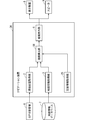
図1に示すように、ナビゲーション装置1は、現在位置取得部2と、地図情報取得部3と、経路算出部4と、経路案内部5とを備えている。現在位置取得部2は、GPS受信機6に接続されている。地図情報取得部3は、地図情報データベース7に接続されている。経路案内部5は、表示装置8およびスピーカ9に接続されている。
現在位置取得部2は、GPS受信機6から、車両の現在位置およびその高度を取得する。GPS受信機6は、車両に設置されており、GPS衛星から、GPS受信機6を設置している車両の現在位置およびその高度を含むGPS信号を受信する。なお、現在位置取得部2は、GPS受信機6から取得した現在位置と、車両の速度、移動距離、および操舵方向などとに基づいて、車両のより正確な現在位置を求めてもよい。GPS受信機6は、ナビゲーション装置1が備えてもよい。
地図情報取得部3は、地図情報データベース7から、位置およびその高度を含む地図情報を取得する。地図情報データベース7は、例えばハードディスクドライブまたは半導体メモリなどの記憶装置から構成されており、少なくとも任意の位置およびその高度を含む地図情報を記憶している。なお、地図情報データベース7は、車両に設置してもよく、車両外に設置してもよい。また、地図情報データベース7は、ナビゲーション装置1が備えてもよい。
経路算出部4は、地図情報取得部3が取得した地図情報に基づいて、現在位置取得部2が取得した現在位置から予め設定した目的地までの経路を算出する。運転者などのユーザは、図示しない入力装置を用いて目的地を設定する。
経路案内部5は、経路算出部4が算出した経路を案内する。具体的には、経路案内部5は、経路を表示装置8に表示したり、経路に関する案内をスピーカ9から音声出力したりする。また、経路案内部5は、目的地の高度と現在位置の高度との高度差である第1高度差、または目的地の高度と最終案内地の高度との高度差である第2高度差に基づいて、第1高度差または第2高度差に関する情報を2次元の地図上に表示する。
表示装置8としては、例えばHUD(Head Up Display)、CID(Central Information Display)、およびインストルメントパネル内に設けられた表示器などが挙げられる。表示装置8は、これらはいずれか1つで構成されてもよく、任意の組み合わせで構成されてもよい。
図2は、ナビゲーション装置1のハードウェア構成の一例を示すブロック図である。
ナビゲーション装置1における現在位置取得部2、地図情報取得部3、経路算出部4、および経路案内部5の各機能は、処理回路により実現される。すなわち、ナビゲーション装置1は、車両の現在位置およびその高度を取得し、位置およびその高度を含む地図情報を取得し、経路を算出し、経路を案内し、高度差に関する情報を通知するための処理回路を備える。処理回路は、メモリ11に格納されたプログラムを実行するプロセッサ10(中央処理装置、処理装置、演算装置、マイクロプロセッサ、マイクロコンピュータ、DSP(Digital Signal Processor)ともいう)である。
ナビゲーション装置1における現在位置取得部2、地図情報取得部3、経路算出部4、および経路案内部5の各機能は、ソフトウェア、ファームウェア、またはソフトウェアとファームウェアとの組み合わせにより実現される。ソフトウェアまたはファームウェアは、プログラムとして記述され、メモリ11に格納される。処理回路は、メモリ11に記憶されたプログラムを読み出して実行することにより、各部の機能を実現する。すなわち、ナビゲーション装置1は、車両の現在位置およびその高度を取得するステップ、位置およびその高度を含む地図情報を取得するステップ、経路を算出するステップ、経路を案内するステップ、高度差に関する情報を通知するステップが結果的に実行されることになるプログラムを格納するためのメモリ11を備える。また、これらのプログラムは、現在位置取得部2、地図情報取得部3、経路算出部4、および経路案内部5の手順または方法をコンピュータに実行させるものであるともいえる。ここで、メモリとは、例えば、RAM(Random Access Memory)、ROM(Read Only Memory)、フラッシュメモリ、EPROM(Erasable Programmable Read Only Memory)、EEPROM(Electrically Erasable Programmable Read Only Memory)等の不揮発性または揮発性の半導体メモリ、磁気ディスク、フレキシブルディスク、光ディスク、コンパクトディスク、ミニディスク、DVD等、または、今後使用されるあらゆる記憶媒体であってもよい。
<動作>
図3は、ナビゲーション装置1の動作の一例を示すフローチャートである。
図3は、ナビゲーション装置1の動作の一例を示すフローチャートである。
ステップS101において、経路算出部4は、現在位置から目的地までの経路を算出する。具体的には、経路算出部4は、地図情報取得部3が取得した地図情報を用いて、現在位置取得部2が取得した現在位置から運転者などが設定した目的地までの経路を算出する。
ステップS102において、経路算出部4は、車両が目的地に近づいたか否かを判断する。具体的には、経路算出部4は、現在位置取得部2が取得した現在位置と、地図情報取得部3が取得した地図情報とに基づいて、車両が目的地に近づいたか否かを判断する。ここで、車両が目的地に近づいたとは、例えば車両が目的地から30m以内に存在することをいう。このとき、目的地からの距離は30mに限らないが、目的地近傍であることが望ましい。車両が目的地に近づくまでステップS102の処理を繰り返し、車両が目的地に近づくとステップS103に移行する。
ステップS103において、経路算出部4は、目的地の高度と現在位置の高度との高度差を算出する。具体的には、経路算出部4は、地図情報取得部3が取得した目的地の高度と、現在位置取得部2が取得した現在位置の高度との差を高度差として算出する。
ステップS104において、経路算出部4は、ステップS103で算出した高度差が設定値以上であるか否かを判断する。高度差の設定値は、例えば10mでもよいが、これに限るものではない。高度差が設定値以上でない場合は、ステップS105に移行する。一方、高度差が設定値以上である場合は、ステップS107に移行する。
ステップS105において、経路案内部5は、高度差を考慮しない目的地情報を表示装置8に表示する。具体的には、表示装置8が図4に示すようなHUDである場合において、経路案内部5は、例えば目的地の方向を示す矢印をHUDに表示する。また、表示装置8が図5に示すようなCIDである場合において、経路案内部5は、例えば目的地の方向を示す矢印をCIDに表示する。図5において、矢印は地図上に表示されている。なお、経路案内部5は、HUDおよびCIDに目的地の方向を示す矢印を同時に表示してもよい。
ステップS106において、経路算出部4は、車両が最終案内地に到着したか否かを判断する。ステップS104で高度差が設定値以上でないと判断されているため、最終案内地と目的地とは一致する場合がある。すなわち、ステップS106で車両が最終案内地に到着したと判断することには、車両が目的地に到着したことが含まれる。車両が最終案内地に到着した場合は、処理を終了する。一方、車両が最終案内地に到着していない場合は、ステップS105に戻る。
ステップS107において、経路案内部5は、高度差を考慮した目的地情報を表示装置8に表示する。具体的には、表示装置8が図6に示すようなHUDである場合において、経路案内部5は、例えば目的地の方向および高度差を示す矢印をHUDに表示する。また、表示装置8が図7に示すようなCIDである場合において、経路案内部5は、例えば目的地の方向および高度差を示す矢印をCIDに表示する。図7において、矢印は地図上に表示されている。なお、経路案内部5は、HUDおよびCIDに目的地の方向および高度差を示す矢印を同時に表示してもよい。
ステップS108において、経路算出部4は、車両が最終案内地に到着したか否かを判断する。ステップS104で高度差が設定値以上であると判断されているため、最終案内地と目的地とは一致しない。すなわち、ステップS106で車両が最終案内地に到着したと判断されても、車両は目的地に到着しているわけではない。車両が最終案内地に到着した場合は、ステップS109に移行する。一方、車両が最終案内地に到着していない場合は、ステップS107に戻る。
ステップS109において、経路案内部5は、最終的な目的地情報を表示装置8に表示する。例えば、経路案内部5は、図8に示すような矢印オブジェクト12を表示装置8であるHUDに表示する。矢印オブジェクト12は、最終的な目的地情報に相当する。図8において、矢印オブジェクト12は、最終案内地Csと目的地Ceとを結ぶ直線であり、矢印の方向に目的地が存在することを示している。平面に対する矢印オブジェクト12の傾きは、最終案内地Csから目的地Ceを見たときの仰角に相当する。なお、最終案内地Csと目的地Ceとの距離が長いほど矢印オブジェクト12を長くするなど、最終案内地Csと目的地Ceとの距離に応じて矢印オブジェクト12の長さを変えてもよい。また、矢印オブジェクト12とともに、最終案内地Csと目的地Ceとの距離を示す数値を表示してもよい。この場合、矢印オブジェクト12と距離を示す数値との組み合わせが、最終的な目的地情報に相当する。
図9,10は、矢印オブジェクト12の一例を示す図である。図9,10に示すように、矢印オブジェクト12は曲線であってもよい。図10に示す矢印オブジェクト12は、図9に示す矢印オブジェクト12よりも高度差が大きいことを示している。すなわち、経路案内部5は、最終案内地と目的地との高度差が大きいほど、(Z軸方向の距離|Ce-Cs|)/(XY平面における距離|Ce-Cs|)を大きくした矢印オブジェクト12を表示する。なお、図9,10に示す矢印オブジェクト12とともに、図11に示すような数値オブジェクト13を表示してもよい。この場合、矢印オブジェクト12および数値オブジェクト13の組み合わせが、最終的な目的地情報に相当する。数値オブジェクト13は、最終案内地Csと目的地Ceとの距離でもよく、最終案内地Csと目的地Ceとの高度差でもよい。また、図9,10に示す矢印オブジェクト12とともに、図12に示すような比較物オブジェクト14を表示してもよい。この場合、矢印オブジェクト12および比較物オブジェクト14の組み合わせが、最終的な目的地情報に相当する。比較物オブジェクト14は、例えば人物であるが、これに限るものではない。矢印オブジェクト12とともに比較物オブジェクト14を表示することによって、最終案内地Csと目的地Ceとの高度差を容易に知ることができる。
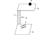
図13は、最終的な目的地情報の一例を示す図であり、最終案内地Csよりも高い場所に目的地が存在することをデフォルメしたものである。図13において、最終案内地Csには自車両オブジェクト15が示されている。目的地Ceには目的地オブジェクト16が示されている。最終案内地Csと目的地Ceとを結ぶように歩行経路オブジェクト17が示されている。歩行経路オブジェクト17とともに、最終案内地Csと目的地Ceとの距離または高度差を示す数値オブジェクト13が示されている。
図14~16は、最終案内地から目的地が見えないときに表示装置8であるHUDに表示する、最終的な目的地情報の一例を示す図である。なお、HUDは、車両のフロントガラスの全面に対応しているものとする。
図14は、最終的な目的地情報を表示していない場合を示している。運転者は、HUD越しに山18~20を見ている。
図15は、山18に目的地があり、当該目的地が山18の木々などによって見えない場合を示している。この場合、目的地オブジェクト16は、山18における目的地に対応する位置に表示される。なお、目的地オブジェクト16は、目的地の属性に基づく形状でもよく、目的地の写真画像であってもよい。目的地の属性に基づく形状とは、目的地を連想する形状のことであり、例えば目的地が神社である場合、目的地オブジェクト16は神社を表す形状となる。
図16は、山19に目的地があり、当該目的地が手前の山18に隠れて見えない場合を示している。この場合、目的地オブジェクト16は、山19における目的地に対応する位置に表示される。なお、図16に示す目的地オブジェクト16は、図15に示す目的地オブジェクト16とは異なる表示形態である。例えば、図16に示す目的地オブジェクト16は、図15に示す目的地オブジェクト16とは異なる形状でもよく、異なる色でもよい。また、図16に示す目的地オブジェクト16は、点滅させてもよい。
<変形例1>
図3のステップS104において、経路算出部4は、高度差が設定値以上であるか否かを判断したが、これに限るものではない。例えば、経路算出部4は、現在位置から目的地を見たときの仰角が設定値以上であるか否かを判断してもよい。なお、仰角の設定値は、例えば30度でもよいが、これに限るものではない。
図3のステップS104において、経路算出部4は、高度差が設定値以上であるか否かを判断したが、これに限るものではない。例えば、経路算出部4は、現在位置から目的地を見たときの仰角が設定値以上であるか否かを判断してもよい。なお、仰角の設定値は、例えば30度でもよいが、これに限るものではない。
図17は、現在位置から目的地を見たときの仰角を説明するための図である。図17において、P1、P2、およびP3は、目的地Dに対する現在位置を示している。P1は、目的地Dから50m離れており、かつ目的地Dよりも30m低い位置であることを示している。P2は、目的地Dから30m離れており、かつ目的地Dよりも25m低い位置であることを示している。P3は、目的地Dから10m離れており、かつ目的地Dよりも20m低い位置であることを示している。また、P1から目的地Dを見たときの仰角はθ1、P2から目的地Dを見たときの仰角はθ2、P3から目的地Dを見たときの仰角はθ3である。図17の例では、θ3>θ2>θ1の関係が成り立っている。
経路算出部4は、現在位置から目的地を見たときの仰角が例えばθ1になったとき、現在位置から目的地を見たときの仰角が設定値以上であるか否かを判断する。
図18~20は、仰角に応じた目的地情報の一例を示す図である。目的地情報は、図3のステップS107において、経路案内部5によって表示装置8に表示される。図18に示す矢印は、例えば図17に示すP1のときに表示される目的地情報である。図19に示す矢印は、例えば図17に示すP2のときに表示される目的地情報である。図20に示す矢印は、例えば図17に示すP3のときに表示される目的地情報である。このように、仰角に応じて矢印の色調を変えてもよい。例えば、仰角が小さいときは寒色で表現し、仰角が大きいときは暖色で表現してもよい。また、各矢印は、仰角に応じて形状を変えてもよい。
なお、図18~20では、仰角に応じて矢印の色調を変えることについて説明したが、これに限るものではない。例えば、現在位置と目的地との高度差に応じて矢印の色調を変えてもよい。
<変形例2>
図3では、車両が目的地に近づいたときの動作について説明したが、これに限るものではない。例えば、車両が経由地に近づいたときも同様の動作を行うことができる。すなわち、車両が経由地に近づき、経由地と現在位置との高度差が設定値以上であるとき、高度差を考慮した目的地情報を表示すればよい。また、高度差に限らず、変形例1のような仰角を適用してもよい。
図3では、車両が目的地に近づいたときの動作について説明したが、これに限るものではない。例えば、車両が経由地に近づいたときも同様の動作を行うことができる。すなわち、車両が経由地に近づき、経由地と現在位置との高度差が設定値以上であるとき、高度差を考慮した目的地情報を表示すればよい。また、高度差に限らず、変形例1のような仰角を適用してもよい。
<変形例3>
図3のステップS107において、経路案内部5は、図8~12に示す情報を表示装置8に表示してもよい。この場合、図8~12におけるCsは現在位置に相当する。図8~12に示す情報は、2次元平面で擬似的な3次元で表示してもよく、裸眼で立体視可能な3次元で表示してもよい。
図3のステップS107において、経路案内部5は、図8~12に示す情報を表示装置8に表示してもよい。この場合、図8~12におけるCsは現在位置に相当する。図8~12に示す情報は、2次元平面で擬似的な3次元で表示してもよく、裸眼で立体視可能な3次元で表示してもよい。
<変形例4>
図3では、現在位置よりも目的地が高い位置にある場合について説明したが、これに限るものではない。現在位置よりも目的地が低い位置にある場合であっても図3を適用することができる。
図3では、現在位置よりも目的地が高い位置にある場合について説明したが、これに限るものではない。現在位置よりも目的地が低い位置にある場合であっても図3を適用することができる。
<変形例5>
図3のステップS104では、判断基準となる高度差を予め設定している場合について説明したが、これに限るものではない。目的地近傍の地形種別によって基準となる高度差を修正してもよい。例えば、山間部は市街地よりも見通しが良いため基準となる高度差を5m高くし、住宅密集地では基準となる高度差を5m低くしてもよい。
図3のステップS104では、判断基準となる高度差を予め設定している場合について説明したが、これに限るものではない。目的地近傍の地形種別によって基準となる高度差を修正してもよい。例えば、山間部は市街地よりも見通しが良いため基準となる高度差を5m高くし、住宅密集地では基準となる高度差を5m低くしてもよい。
目的地の地物が他の地物に隠れて視認できないときは、基準となる高度差を低くしてもよい。また、最終案内地から目的地が視認できないときは、基準となる高度差を低くしてもよい。
<変形例6>
図3では、車両が目的に近づいたときに最終的な目的地情報を表示することについて説明したが、これに限るものではない。例えば、経路を算出して運転者に経路を提示するタイミング、経路案内中の任意のタイミング、運転者が要求する任意のタイミング、または目的地を視認することができるタイミングで最終的な目的地情報を表示してもよい。
図3では、車両が目的に近づいたときに最終的な目的地情報を表示することについて説明したが、これに限るものではない。例えば、経路を算出して運転者に経路を提示するタイミング、経路案内中の任意のタイミング、運転者が要求する任意のタイミング、または目的地を視認することができるタイミングで最終的な目的地情報を表示してもよい。
ここで、目的地を視認することができるタイミングとは、現在位置と地図情報とに基づいて、現在位置から目的地の間に遮るものがないときのことをいう。この場合、表示装置8であるHUDにおける目的地に対応する位置に、目的地を示すオブジェクトを表示してもよい。
<変形例7>
上記では、2次元の地図を表示する場合について説明したがこれに限るものではない。例えば、3次元の地図、鳥瞰図で表現した地図、運転者目線を表現したクルージングビューの地図などでもよい。ただし、地図を3次元で表現すると地図を描画するための処理負荷が大きくなる。特に、目的地付近で縮尺が小さく画面更新が頻繁に発生する場合、描画を処理するための時間がかかるなどのデメリットがある。
上記では、2次元の地図を表示する場合について説明したがこれに限るものではない。例えば、3次元の地図、鳥瞰図で表現した地図、運転者目線を表現したクルージングビューの地図などでもよい。ただし、地図を3次元で表現すると地図を描画するための処理負荷が大きくなる。特に、目的地付近で縮尺が小さく画面更新が頻繁に発生する場合、描画を処理するための時間がかかるなどのデメリットがある。
<変形例8>
図3において、目的地に近づくまでの間に、交差点などで右左折の案内する際にランドマークを表示することがある。このとき、運転者が容易にランドマークの場所を把握することができるように、現在位置とランドマークとの高度差を表示してもよい。
図3において、目的地に近づくまでの間に、交差点などで右左折の案内する際にランドマークを表示することがある。このとき、運転者が容易にランドマークの場所を把握することができるように、現在位置とランドマークとの高度差を表示してもよい。
<変形例9>
図3のステップS108において、経路案内部5は、最終的な目的地情報を表示装置8に表示するときに、高度差を考慮した音声をスピーカ9から出力してもよい。
図3のステップS108において、経路案内部5は、最終的な目的地情報を表示装置8に表示するときに、高度差を考慮した音声をスピーカ9から出力してもよい。
例えば、最終案内地よりも目的地が高い場所にあるとき、経路案内部5は、車両が最終案内地に到着したことを知らせる音声を、車両内の上部に設置されたスピーカ9から出力する。また、最終案内地よりも目的地が低い場所にあるとき、経路案内部5は、車両が最終案内地に到着したことを知らせる音声を、車両内の下部に設置されたスピーカ9から出力する。これにより、運転者は、音声から目的地の方向を把握することができる。
また、運転者が目的地の方向から音声が聞こえるようにするために音像定位を用いてもよい。音像定位は、2個以上のスピーカ9による周知の方法で実現することができる。周知の方法としては、ステレオ方式、サラウンド方式、または擬似サラウンド方式などがある。また、例えば図8~12に示す矢印の形状に従って、音像定位を時間的に変化させるようにしてもよい。
以上のことから、本実施の形態1によれば、目的地に近づき、現在位置と目的地との高度差が設定値以上であるとき、現在位置と目的地との高度差を示す目的地情報を表示する。その後、最終案内地に到着したとき、最終案内地と目的地との高度差を示す最終的な目的地情報を表示する。これにより、現在位置または最終案内地と目的地との高度差を考慮した目的地情報を提示することができるため、最終案内地から目的地が視認しづらいときも容易に目的地の場所を知ることができる。また、目的地情報とともに2次元の地図を表示しているため、高度差を考慮した目的地情報を提示する際の処理負荷を低減することができる。
<実施の形態2>
<構成>
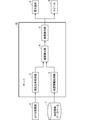
図21は、本発明の実施の形態2によるナビゲーション装置21の構成の一例を示すブロック図である。
<構成>
図21は、本発明の実施の形態2によるナビゲーション装置21の構成の一例を示すブロック図である。
図21に示すように、ナビゲーション装置21は、通信部22および経路算出部23を備えることを特徴としている。その他の構成は、実施の形態1によるナビゲーション装置1と同様であるため、ここでは詳細な説明を省略する。
通信部22は、外部と通信して交通機関情報を取得する。交通機関情報は、鉄道、バス、ロープウェイなどの駅の位置、時刻表などの情報を含む。
経路算出部23は、目的地の高度と最終案内地の高度との高度差が予め定められた閾値以上であるとき、最終案内地から目的地までの車両以外の移動手段を含む経路を算出する。
ナビゲーション装置21における通信部22および経路算出部23の各機能は、処理回路により実現される。すなわち、ナビゲーション装置21は、交通機関情報を取得し、最終案内地から目的地までの車両以外の移動手段を含む経路を算出するための処理回路を備える。処理回路は、図2に示すような、メモリ11に格納されたプログラムを実行するプロセッサ10である。
ナビゲーション装置21における通信部22および経路算出部23の各機能は、ソフトウェア、ファームウェア、またはソフトウェアとファームウェアとの組み合わせにより実現される。ソフトウェアまたはファームウェアは、プログラムとして記述され、図2に示すようなメモリ11に格納される。処理回路は、メモリ11に記憶されたプログラムを読み出して実行することにより、各部の機能を実現する。すなわち、ナビゲーション装置21は、交通機関情報を取得するステップ、最終案内地から目的地までの車両以外の移動手段を含む経路を算出するステップが結果的に実行されることになるプログラムを格納するためのメモリ11を備える。また、これらのプログラムは、通信部22および経路算出部23の手順または方法をコンピュータに実行させるものであるともいえる。
<動作>
図22は、ナビゲーション装置21の動作の一例を示すフローチャートである。
図22は、ナビゲーション装置21の動作の一例を示すフローチャートである。
ステップS201において、通信部22は、外部から交通機関情報を取得する。
ステップS202において、経路算出部23は、地図情報取得部3から、運転者などのユーザが設定した目的地に関する情報である目的地情報を取得する。目的地情報には、目的地の位置およびその高度が含まれている。
ステップS203において、経路算出部23は、移動に車両のみを用いたときの最終案内地を求める。具体的には、経路算出部23は、地図情報取得部3が取得した地図情報を用いて、設定した目的地の近くであり、かつ車両で到達するよう案内される地点を最終案内地とする。
ステップS204において、経路算出部23は、地図情報取得部3から、最終案内地に関する情報である最終案内地情報を取得する。最終案内地情報には、最終案内地の位置およびその高度が含まれている。
ステップS205において、経路算出部23は、目的地の高度と最終案内地の高度との高度差を算出する。
ステップS206において、経路算出部23は、ステップS205で算出した高度差が設定値以上であるか否かを判断する。高度差が設定値以上である場合は、ステップS208に移行する。一方、高度差が設定値以上でない場合は、ステップS207に移行する。
ステップS207において、経路算出部23は、現在位置から目的地までの経路を算出する。
ステップS208において、経路算出部23は、通信部22が取得した交通機関情報から、目的地周辺の交通機関情報を検索する。
ステップS209において、経路算出部23は、交通機関を考慮した現在位置から目的地までの経路を算出する。
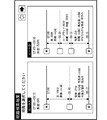
ステップS210において、経路案内部5は、経路算出部23が算出した経路を表示装置8に提示し、運転者に選択させる。図23は、経路案内部5が複数の経路を提示している一例を示している。図23では、経路算出部23がルートAおよびルートBを算出した場合を示している。ルートAは、最終案内地から目的地まで、徒歩で27分かかることを示している。ルートBは、最終案内地から目的地まで、ロープウェイで45分、および徒歩で2分かかることを示している。運転者は、表示装置8に表示されたルートAまたはルートBを選択する。なお、経路算出部23が算出した経路が1つである場合、ステップS210の処理は省略してもよい。
ステップS211において、経路案内部5は、ステップS207で経路算出部23が算出した経路、またはステップS210で運転者が選択した経路の案内を開始する。
地図上で最終案内地と目的地との距離が近い場合であっても、最終案内地と目的地との間に高度差があれば徒歩で移動するための労力がかかる。この場合、目的地までの経路としては最適であるとはいえない。このような問題を解決するために、本実施の形態2では、最終案内地と目的地との間に高度差がある場合、他の交通機関を含めた経路を運転者に提案する。例えば、山地でロープウェイを利用することによって、車のみで到達する最終案内地よりも目的地に接近することができる場合は、「車+徒歩」の経路だけでなく、「車+ロープウェイ+徒歩」の経路も運転者に提示する。これにより、運転者は、目的地に到着するまでに要する費用、時間、および徒歩による労力などを考慮して経路を選択することができる。
なお、本実施の形態2は、実施の形態1と組み合わせてもよい。また、実施の形態1における各変形例は、矛盾しない範囲で本実施の形態2に適用してもよい。
<実施の形態3>
<構成>
図24は、本発明の実施の形態3によるナビゲーション装置24の構成の一例を示すブロック図である。
<構成>
図24は、本発明の実施の形態3によるナビゲーション装置24の構成の一例を示すブロック図である。
図24に示すように、ナビゲーション装置24は、災害情報取得部25および経路算出部26を備えることを特徴としている。その他の構成は、実施の形態1によるナビゲーション装置1と同様であるため、ここでは詳細な説明を省略する。
災害情報取得部25は、ダイナミックマップに含まれている災害情報を取得する。当該災害情報には、災害発生の位置およびその高度が含まれている。ダイナミックマップは、災害情報、事故情報、渋滞情報、および気象情報などの動的な情報を組み込んだデジタル地図である。本実施の形態3で想定している災害としては、例えば、水害、地滑り、火砕流、噴火による溶岩流出、津波など、災害発生の位置の高度から災害が影響する範囲を推定することが可能な災害が挙げられる。
経路算出部26は、現在位置取得部2が取得した現在位置から、運転者などのユーザが設定した目的地までの経路を算出する。また、経路算出部26は、経路付近で災害が発生した場合において、現在位置取得部2が取得した現在位置の高度と、災害情報取得部25が取得した災害発生時の位置の高度とに基づいて、災害の影響を回避した経路を算出する。
ナビゲーション装置24における災害情報取得部25および経路算出部26の各機能は、処理回路により実現される。すなわち、ナビゲーション装置24は、災害情報を取得し、災害の影響を回避した経路を算出するための処理回路を備える。処理回路は、図2に示すような、メモリ11に格納されたプログラムを実行するプロセッサ10である。
ナビゲーション装置24における災害情報取得部25および経路算出部26の各機能は、ソフトウェア、ファームウェア、またはソフトウェアとファームウェアとの組み合わせにより実現される。ソフトウェアまたはファームウェアは、プログラムとして記述され、図2に示すようなメモリ11に格納される。処理回路は、メモリ11に記憶されたプログラムを読み出して実行することにより、各部の機能を実現する。すなわち、ナビゲーション装置24は、災害情報を取得するステップ、災害の影響を回避した経路を算出するステップが結果的に実行されることになるプログラムを格納するためのメモリ11を備える。また、これらのプログラムは、災害情報取得部25および経路算出部26の手順または方法をコンピュータに実行させるものであるともいえる。
<動作>
図25は、ナビゲーション装置24の動作の一例を示すフローチャートである。なお、図26に示すように、車両は経路27を走行中であるものとする。
図25は、ナビゲーション装置24の動作の一例を示すフローチャートである。なお、図26に示すように、車両は経路27を走行中であるものとする。
ステップS301において、災害情報取得部25は、災害情報を取得したか否かを判断する。災害情報を取得するまでステップS301の処理を繰り返し、災害情報を取得するとステップS302に移行する。
ステップS302において、経路算出部26は、地図情報取得部3から、災害発生の位置およびその高度を含む災害発生地情報を取得する。以下では、災害発生の位置のことを災害発生地ともいう。
ステップS303において、経路算出部26は、災害発生地の高度と、災害発生地周辺の高度とに基づいて、今後の災害が影響する範囲を推定する。図27は、災害が影響する範囲を推定した結果を示している。図27の例では、川28の水害発生地点29で水害が発生したことを示している。経路算出部26は、災害発生地の高度と、災害発生地周辺の高度とに基づいて、今後の災害が影響する範囲である影響範囲30を推定する。例えば水害の場合、経路算出部26は、水害発生地点29よりも高度が低い、あるいは水害発生地点29と高度が同じ場所は水害が影響する範囲であると推定する。
ステップS304において、経路算出部26は、推定した範囲内に案内中の経路が含まれているか否かを判断する。具体的には、経路算出部26は、図26に示す案内中の経路27と、図27に示す影響範囲30とを参照し、影響範囲30内に案内中の経路27が含まれているか否かを判断する。図26,27の例では、影響範囲30内に案内中の経路27が含まれている。推定した範囲内に案内中の経路が含まれている場合は、ステップS305に移行する。一方、推定した範囲内に案内中の経路が含まれていない場合は、処理を終了する。
ステップS305において、経路算出部26は、推定した範囲を回避する経路を再算出する。図27の例では、経路算出部26は、影響範囲30を回避する新経路31を再算出する。このとき、経路案内部5は、図27に示すような「災害発生のため、経路を変更します」といったメッセージを表示装置8に表示してもよい。
ステップS306において、経路案内部5は、経路算出部26が再算出した新たな経路の案内を開始する。図27の例では、経路案内部5は、経路算出部26が再算出した新経路31の案内を開始する。
以上のことから、本実施の形態3によれば、取得した災害情報から今後の災害が影響する範囲を推定し、当該推定した範囲を回避する経路を再算出する。これにより、運転者は災害の影響を回避することができる。
なお、本実施の形態3は、実施の形態1および実施の形態2のうちの少なくとも一方と組み合わせてもよい。また、実施の形態1における各変形例は、矛盾しない範囲で本実施の形態3に適用してもよい。
以上で説明したナビゲーション装置は、車載用ナビゲーション装置、すなわちカーナビゲーション装置だけでなく、車両に搭載可能なPND(Portable Navigation Device)、および車両の外部に設けられるサーバなどを適宜に組み合わせてシステムとして構築されるナビゲーション装置にも適用することができる。この場合、ナビゲーション装置の各機能あるいは各構成要素は、上記システムを構築する各機能に分散して配置される。
具体的には、一例として、ナビゲーション装置の機能をサーバに配置することができる。例えば、図28に示すように、ユーザ側は、GPS受信機6、表示装置8、およびスピーカ9を備えている。サーバ32は、現在位置取得部2、地図情報取得部3、経路算出部4、および経路案内部5を備えている。地図情報データベース7は、サーバ32が備えてもよく、サーバ32の外部に設けてもよい。このような構成とすることによって、ナビゲーションシステムを構築することができる。図21,24についても同様である。
このように、ナビゲーション装置の各機能を、システムを構築する各機能に分散して配置した構成であっても、上記の実施の形態と同様の効果が得られる。
また、上記の実施の形態における動作を実行するソフトウェアを、例えばサーバに組み込んでもよい。このソフトウェアをサーバが実行することにより実現されるナビゲーション方法は、車両の現在位置およびその高度を取得し、位置およびその高度を含む地図情報を取得し、取得した地図情報に基づいて、取得した現在位置から予め設定した目的地までの経路を算出し、算出した経路を案内し、案内することは、目的地の高度と現在位置の高度との高度差である第1高度差、または目的地の高度と車両が最終的に到達するよう案内される最終案内地の高度との高度差である第2高度差に基づいて、第1高度差または第2高度差に関する情報を2次元の地図上に表示することを含むことである。
このように、上記の実施の形態における動作を実行するソフトウェアをサーバに組み込んで動作させることによって、上記の実施の形態と同様の効果が得られる。
なお、本発明は、その発明の範囲内において、各実施の形態を自由に組み合わせたり、各実施の形態を適宜、変形、省略することが可能である。
本発明は詳細に説明されたが、上記した説明は、すべての態様において、例示であって、この発明がそれに限定されるものではない。例示されていない無数の変形例が、この発明の範囲から外れることなく想定され得るものと解される。
1 ナビゲーション装置、2 現在位置取得部、3 地図情報取得部、4 経路算出部、5 経路案内部、6 GPS受信機、7 地図情報データベース、8 表示装置、9 スピーカ、10 プロセッサ、11 メモリ、12 矢印オブジェクト、13 数値オブジェクト、14 比較物オブジェクト、15 自車両オブジェクト、16 目的地オブジェクト、17 歩行経路オブジェクト、18,19,20 山、21 ナビゲーション装置、22 通信部、23 経路算出部、24 ナビゲーション装置、25 災害情報取得部、26 経路算出部、27 経路、28 川、29 水害発生地点、30 影響範囲、31 新経路、32 サーバ。
Claims (10)
- 車両の現在位置およびその高度を取得する現在位置取得部と、
位置およびその高度を含む地図情報を取得する地図情報取得部と、
前記地図情報取得部が取得した前記地図情報に基づいて、前記現在位置取得部が取得した前記現在位置から予め設定した目的地までの経路を算出する経路算出部と、
前記経路算出部が算出した前記経路を案内する経路案内部と、
を備え、
前記経路案内部は、前記目的地の高度と前記現在位置の高度との高度差である第1高度差、または前記目的地の高度と前記車両が最終的に到達するよう案内される最終案内地の高度との高度差である第2高度差に基づいて、前記第1高度差または前記第2高度差に関する情報を2次元の地図上に表示することを特徴とする、ナビゲーション装置。 - 前記経路案内部は、前記第1高度差または第2高度差が予め定められた閾値以上であるとき、前記第1高度差または第2高度差に関する情報を表示することを特徴とする、請求項1に記載のナビゲーション装置。
- 前記経路案内部は、前記第1高度差または第2高度差に応じて前記第1高度差または第2高度差に関する情報の表示形態を異ならせることを特徴とする、請求項2に記載のナビゲーション装置。
- 災害発生の位置およびその高度を含む災害情報を取得する災害情報取得部をさらに備え、
前記経路算出部は、前記現在位置取得部が取得した前記現在位置の高度と、前記災害情報取得部が取得した前記災害発生の位置の高度とに基づいて、前記経路を算出することを特徴とする、請求項1に記載のナビゲーション装置。 - 前記経路算出部は、前記災害発生の位置の高度よりも低い高度の位置を回避した前記経路を算出することを特徴とする、請求項4に記載のナビゲーション装置。
- 前記目的地は、経由地を含むことを特徴とする、請求項1に記載のナビゲーション装置。
- 車両の現在位置を取得する現在位置取得部と、
位置およびその高度を含む地図情報を取得する地図情報取得部と、
前記地図情報取得部が取得した前記地図情報に基づいて、前記現在位置取得部が取得した前記現在位置から予め設定した目的地までの経路を算出する経路算出部と、
前記経路算出部が算出した前記経路を案内する経路案内部と、
を備え、
前記経路算出部は、前記目的地の高度と前記車両が最終的に到達するよう案内される最終案内地の高度との高度差が予め定められた閾値以上であるとき、前記最終案内地から前記目的地までの前記車両以外の移動手段を含む前記経路を算出することを特徴とする、ナビゲーション装置。 - 前記経路算出部が複数の経路を算出したとき、前記経路案内部は、選択された一の前記経路を案内することを特徴とする、請求項7に記載のナビゲーション装置。
- 前記移動手段は、徒歩および交通機関の利用のうちの少なくとも1つを含むことを特徴とする、請求項7に記載のナビゲーション装置。
- 車両の現在位置およびその高度を取得し、
位置およびその高度を含む地図情報を取得し、
取得した前記地図情報に基づいて、取得した前記現在位置から予め設定した目的地までの経路を算出し、
算出した前記経路を案内し、
前記案内することは、前記目的地の高度と前記現在位置の高度との高度差である第1高度差、または前記目的地の高度と前記車両が最終的に到達するよう案内される最終案内地の高度との高度差である第2高度差に基づいて、前記第1高度差または前記第2高度差に関する情報を2次元の地図上に表示することを含む、ナビゲーション方法。
Priority Applications (1)
| Application Number | Priority Date | Filing Date | Title |
|---|---|---|---|
| PCT/JP2018/018904 WO2019220558A1 (ja) | 2018-05-16 | 2018-05-16 | ナビゲーション装置およびナビゲーション方法 |
Applications Claiming Priority (1)
| Application Number | Priority Date | Filing Date | Title |
|---|---|---|---|
| PCT/JP2018/018904 WO2019220558A1 (ja) | 2018-05-16 | 2018-05-16 | ナビゲーション装置およびナビゲーション方法 |
Publications (1)
| Publication Number | Publication Date |
|---|---|
| WO2019220558A1 true WO2019220558A1 (ja) | 2019-11-21 |
Family
ID=68539787
Family Applications (1)
| Application Number | Title | Priority Date | Filing Date |
|---|---|---|---|
| PCT/JP2018/018904 Ceased WO2019220558A1 (ja) | 2018-05-16 | 2018-05-16 | ナビゲーション装置およびナビゲーション方法 |
Country Status (1)
| Country | Link |
|---|---|
| WO (1) | WO2019220558A1 (ja) |
Cited By (1)
| Publication number | Priority date | Publication date | Assignee | Title |
|---|---|---|---|---|
| JP2024017516A (ja) * | 2022-07-28 | 2024-02-08 | 日本精機株式会社 | 表示制御装置、表示システム、及び表示制御方法 |
Citations (3)
| Publication number | Priority date | Publication date | Assignee | Title |
|---|---|---|---|---|
| JP2002350169A (ja) * | 2001-05-30 | 2002-12-04 | Alpine Electronics Inc | ナビゲーション装置 |
| JP2005189713A (ja) * | 2003-12-26 | 2005-07-14 | Kazuharu Seki | 道路地図 |
| JP2016075499A (ja) * | 2014-10-03 | 2016-05-12 | 株式会社ゼンリンデータコム | 駐車場決定支援装置、注意喚起装置、およびコンピュータプログラム |
-
2018
- 2018-05-16 WO PCT/JP2018/018904 patent/WO2019220558A1/ja not_active Ceased
Patent Citations (3)
| Publication number | Priority date | Publication date | Assignee | Title |
|---|---|---|---|---|
| JP2002350169A (ja) * | 2001-05-30 | 2002-12-04 | Alpine Electronics Inc | ナビゲーション装置 |
| JP2005189713A (ja) * | 2003-12-26 | 2005-07-14 | Kazuharu Seki | 道路地図 |
| JP2016075499A (ja) * | 2014-10-03 | 2016-05-12 | 株式会社ゼンリンデータコム | 駐車場決定支援装置、注意喚起装置、およびコンピュータプログラム |
Cited By (1)
| Publication number | Priority date | Publication date | Assignee | Title |
|---|---|---|---|---|
| JP2024017516A (ja) * | 2022-07-28 | 2024-02-08 | 日本精機株式会社 | 表示制御装置、表示システム、及び表示制御方法 |
Similar Documents
| Publication | Publication Date | Title |
|---|---|---|
| RU2389976C1 (ru) | Навигационное устройство, навигационный сервер и навигационная система | |
| KR100821503B1 (ko) | 차량 항법 시스템에서의 동적 디스플레이 모드 변경 방법및 그 장치 | |
| CN102047302B (zh) | 在三维路径导航系统中改变视角的设备与方法 | |
| US20090240426A1 (en) | Navigation device and navigation method | |
| JP6758516B2 (ja) | 運転支援装置および運転支援方法 | |
| US9026353B2 (en) | Method and apparatus for displaying guidance for navigation system | |
| US11186293B2 (en) | Method and system for providing assistance to a vehicle or driver thereof | |
| US9506764B2 (en) | System and method of generating a route across an electronic map | |
| JP2013104871A (ja) | ナビゲーションシステムおよびその表示方法 | |
| US8862392B2 (en) | Digital map landmarking system | |
| WO2014020887A1 (ja) | ナビゲーション装置 | |
| US20130069941A1 (en) | Navigational aid having improved processing of display data | |
| US11828613B2 (en) | Superimposed-image display device | |
| US10168176B2 (en) | Visualizing unidirectional traffic information | |
| JP2011158281A (ja) | 経路探索装置、経路探索方法、経路探索プログラムおよび記録媒体 | |
| CN103278172A (zh) | 一种路口诱导方法及定位导航设备 | |
| JP5451428B2 (ja) | ナビゲーション装置およびネットワークデータのデータ構造 | |
| JP3428275B2 (ja) | 車両用ナビゲーション装置 | |
| CN117693665A (zh) | 用于提供限速信息的技术 | |
| WO2019220558A1 (ja) | ナビゲーション装置およびナビゲーション方法 | |
| EP3992582B1 (en) | Method, apparatus and computer program product for temporally based dynamic audio shifting | |
| JP2023164659A (ja) | 情報処理装置、情報出力方法、プログラム及び記憶媒体 | |
| JP7145007B2 (ja) | 経路案内システムおよび経路案内プログラム | |
| JP3955482B2 (ja) | 車載ナビゲーションシステム | |
| US20120253666A1 (en) | Movement guidance display system, movement guidance display method, and computer program |
Legal Events
| Date | Code | Title | Description |
|---|---|---|---|
| 121 | Ep: the epo has been informed by wipo that ep was designated in this application |
Ref document number: 18919147 Country of ref document: EP Kind code of ref document: A1 |
|
| NENP | Non-entry into the national phase |
Ref country code: DE |
|
| 122 | Ep: pct application non-entry in european phase |
Ref document number: 18919147 Country of ref document: EP Kind code of ref document: A1 |
|
| NENP | Non-entry into the national phase |
Ref country code: JP |