WO2019218396A1 - 一种智能马桶喷头性能测试系统和测试方法 - Google Patents
一种智能马桶喷头性能测试系统和测试方法 Download PDFInfo
- Publication number
- WO2019218396A1 WO2019218396A1 PCT/CN2018/088938 CN2018088938W WO2019218396A1 WO 2019218396 A1 WO2019218396 A1 WO 2019218396A1 CN 2018088938 W CN2018088938 W CN 2018088938W WO 2019218396 A1 WO2019218396 A1 WO 2019218396A1
- Authority
- WO
- WIPO (PCT)
- Prior art keywords
- nozzle
- water
- grid
- rod
- jet
- Prior art date
- Legal status (The legal status is an assumption and is not a legal conclusion. Google has not performed a legal analysis and makes no representation as to the accuracy of the status listed.)
- Ceased
Links
Images

Classifications
-
- G—PHYSICS
- G01—MEASURING; TESTING
- G01M—TESTING STATIC OR DYNAMIC BALANCE OF MACHINES OR STRUCTURES; TESTING OF STRUCTURES OR APPARATUS, NOT OTHERWISE PROVIDED FOR
- G01M99/00—Subject matter not provided for in other groups of this subclass
- G01M99/005—Testing of complete machines, e.g. washing-machines or mobile phones
Definitions
- the invention relates to the technical field of water jet testing, in particular to a smart toilet nozzle performance testing system and a testing method.
- China Open No. CN204008062U patent provides an integrated test system system for jet flow characteristics of underwater self-inhalation nozzles, which is characterized by not only observing and testing the gas-liquid two-phase flow characteristics of self-suction nozzles. Moreover, the impact flow characteristics of the gas-liquid two-phase jet of the nozzle can be observed and tested to understand the impact performance, but the technical solution cannot obtain the test data scientifically.
- the present invention provides a smart toilet nozzle performance testing system and testing method, which can combine the mechanical property data analysis and the image processing technology to test the mechanical properties, cleaning performance and flow state of the nozzle.
- the present invention achieves the above technical objects by the following technical means.
- a smart toilet nozzle performance testing system comprising a mechanical performance testing device, a cleaning performance testing device, a jet water flow rate testing device, a computer, a water tank, an electronic water pump, a base, a fixed rod A and a fixed rod B mounted on the base;
- the nozzle to be tested is mounted on the fixed rod A, and the electronic water pump draws water from the water tank and adjusts the supply pressure to the nozzle;
- the mechanical property testing device includes a force sensor, a waterproof cover and a signal analysis device, the waterproof cover is mounted on the fixing rod B, the force sensor is installed in the waterproof cover, and the stress sensor is fixed on the force sensor, The spray head is opposite to the stress piece, the force sensor is electrically connected to the signal analysis device, and the signal analysis device is electrically connected to the computer;
- the cleaning performance testing device comprises a grid and an image collecting device.
- the nozzle is facing the grid, and the image collecting device is used for collecting a picture of the grid after the nozzle cleaning, and the image collecting device Electrically connected to the computer to transfer the picture to the image analysis software in the computer;
- the jet hydraulic testing device comprises a high speed camera for photographing the flow pattern of the washing water jet sprayed by the nozzle, the high speed camera is electrically connected with the computer, the photograph is transmitted to a computer, and the computer analyzes the jet water flow rate and the jet. Movement pattern.
- the utility model further comprises a water shield, the waterproof cover is located in the water shield, the water shield is a hollow cube, and the water shield has an upper water barrier and three side water flaps which are sequentially connected vertically, The end of the side flap is fixed to the lower surface of the upper flap, and the water shield is mounted on the base by the support rod.
- one end of the grid is hinged to an end of the upper baffle near the nozzle, and the grid is placed on the upper baffle plate.
- the grid can be folded to the block.
- the side of the water hood is facing the nozzle.
- each square of the grid has a size of 3 mm x 3 mm and a depth of 8 mm, and the length of the grid is greater than the distance between two opposite side flaps on the water shield.
- one side of the force sensor is provided with a stud A, and the stress piece is mounted on the other side opposite to the stud A;
- the waterproof cover has a hollow cylindrical shape, and the waterproof cover is horizontally disposed, and one end surface is provided with a threaded hole D that cooperates with the stud A, and the other end surface is open, and the stress piece is located outside the other end surface of the waterproof cover.
- the stress piece is a circular aluminum plate having a diameter of 25 mm and a thickness of 0.7 mm.
- the base is a rectangular parallelepiped, the upper surface of the base is provided with a groove along the length direction, and the bottom wall of the groove is provided with two rows of threaded holes A;
- the bottom end of the fixing rod A is fixed with a first gasket, and the first gasket is provided with a through hole, and is connected to the threaded hole A through the through hole through the through hole, and the fixing rod B is fixed on the upper surface of the base And close to the groove.
- the fixing rod B comprises a hollow cylindrical rod and a threaded rod, and the inner wall of the hollow cylindrical rod is provided with an internal thread matched with the threaded rod, and the bottom end of the threaded rod is screwed with the hollow cylindrical rod by adjusting the thread
- the rod extends into the hollow cylindrical rod to adjust the height of the fixed rod B, and the top of the threaded rod is fixed with a grip for mounting a waterproof cover, and the fixed rod A and the fixed rod B have the same structure.
- a test method using a smart toilet head performance system specifically:
- the force sensor is zeroed, the parameters of the signal analysis device are set, and the electronic water pump is started. After the nozzle is stabilized, the force sensor transmits the collected signal to the signal analysis device, and the mechanical properties of the nozzle are obtained through computer analysis. parameter;
- the jet water flow rate test can be simultaneously performed, the high-speed camera is adjusted to the focal length, the motion pattern of the washing water is photographed, the picture taken by the high-speed camera is transmitted to the computer, and the jet water flow rate is obtained by the image processing software;
- the jam is applied to the grid and the nozzle is facing the nozzle.
- the electronic water pump is turned off, the grid is photographed by the camera, and the photograph of the photographed grid is transmitted to the image analysis software in the computer to obtain the nozzle. Area cleaning rate and volume cleaning rate.
- the invention controls the distance from the nozzle to the force sensor by moving the position of the fixed rod A to the left and right, thereby obtaining the jet flow mechanical performance data at different distances, and simultaneously shooting the flow pattern of the water jet by high-speed photography, and visually observing the self-mixing gas pulse.
- the jet flow performance of the nozzle can be obtained by using the displacement of the water flow in the two photographs taken by the high speed camera.
- the area cleaning rate of the nozzle and the volume cleaning rate can be measured by the cleaning performance test device.
- the base of the invention has a groove on the base, and two rows of threaded holes A are arranged in the groove, so that the fixed rod A can be conveniently moved, and the fixing rod A can be conveniently installed, so that the nozzle and the force sensor can be conveniently and quickly adjusted. the distance.
- the fixing rod A and the fixing rod B of the invention can be adjusted by the threaded column, and can adapt to the performance requirements of different nozzle structures.
- the water shield of the present invention can prevent the jet water from being splashed into the surrounding environment after hitting the stress piece, and can also be used to fix the grid to prevent the grid from being shaken by the jet water striking force.
- the waterproof cover of the present invention can effectively protect the force sensor from the spatter damage force sensor.
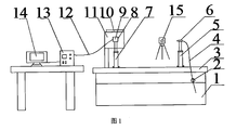
- FIG. 1 is a schematic structural diagram 1 of a smart toilet nozzle performance testing system according to the present invention.
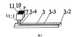
- FIG. 2 is a schematic structural view of the base, the water shield and the grid according to the present invention.
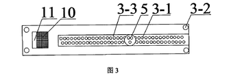
- Figure 3 is a top plan view of the base of the present invention.
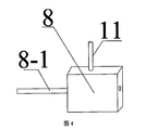
- FIG. 4 is a schematic structural view of the mechanical sensor of the present invention.
- Figure 5 is a schematic view showing the connection of the mechanical sensor and the stress piece according to the present invention.
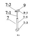
- Figure 6 is a schematic view showing the structure of the fixing rod B of the present invention.
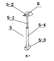
- Figure 7 is a schematic view showing the structure of the fixing rod A of the present invention.
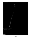
- Figure 8 shows the movement pattern of the washing water obtained by the high speed camera.
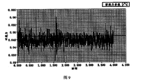
- FIG. 9 is a test parameter of a nozzle obtained according to an embodiment of the present invention.
- a smart toilet nozzle performance testing system includes a mechanical performance testing device, a cleaning performance testing device, a jet water flow rate testing device, a computer 14, a base 3, a water tank 1, and an electronic water pump 2.
- the size of the water tank 1 is 800mm*500mm*600mm, and a threaded hole E is opened at the middle of the upper ends of the water tank 1.
- the base 3 is a rectangular parallelepiped, and the upper surface of the base 3 is opened in the longitudinal direction.
- the groove 3-3, the bottom wall of the groove 3-3 is provided with two rows of second threaded holes A3-1, and the spacing of each of the two threaded holes A in each row of the threaded holes A3-1 is 15 mm, and the base 3
- the threaded holes B3-2 are opened on the four corners, and are fixed to the upper end of the water tank 1 through the studs.
- the fixing rod B7 includes a second hollow cylindrical rod 7-4, a second threaded rod 7-1 and a second spacer 7-3, and the second hollow cylindrical rod 7-4 is provided with an inner wall
- the second threaded rod 7-1 is fitted with an internal thread
- the bottom end of the second threaded rod 7-1 is screwed to the second hollow cylindrical rod 7-4
- the second threaded rod 7-1 is adjusted to extend into the hollow cylindrical rod
- the length of 7-4 adjusts the height of the fixing rod B7
- the top of the second threaded rod 7-1 fixes the second grip 7-2
- the bottom of the second hollow cylindrical rod 7-4 is fixed with the second spacer 7- 3.
- the fixing rod A5 and the fixing rod B7 are identical in structure, and include a first hollow cylindrical rod 5-4, a first threaded column 5-1, a first clamping hand 5-2, and a first spacer 5- 3.
- a through hole is formed in each of the first spacer 5-3 and the second spacer 7-3.
- the upper surface of the base 3 is further provided with three threaded holes C3-4 corresponding to the through holes on the second spacer 7-3, and the second spacer 7-3 of the fixing rod B7 is attached to the upper surface of the base 3.
- the screw is fixedly connected to the threaded hole C3-4 through the stud, and the fixing rod A is connected to the threaded hole A3-1 through the through hole through the stud.
- the nozzle 6 to be tested is mounted on the first clamp 5-2, one end of the electronic water pump 2 is connected to the nozzle 6 through the hose 4, and the other end of the electronic water pump 2 is connected to the water tank 1 through the hose 4, and the electronic water pump 2 is from the water tank 1
- the water is pumped and the supply pressure is adjusted to be delivered to the spray head 6.
- the mechanical property testing device includes a force sensor 8, a waterproof cover 9, and a signal analyzing device 13, as shown in FIG. 4 and FIG. 5, a side of the force sensor 8 is provided with a stud A8-1 having a diameter of 3 mm.
- the stress piece 8-3 is attached to the other side opposite to the stud A8-1 by a bolt 8-2 having a diameter of 3 mm, and the stress piece 8-3 is a circular aluminum plate having a diameter of 25 mm and a thickness of 0.7 mm.
- the force sensor 8 is installed in the waterproof cover 9, and the waterproof cover 9 is installed in the second clamp 7-2.
- the waterproof cover 9 is a hollow cylindrical shape, and the waterproof cover 9 is horizontally disposed, and the side cover of the waterproof cover 9 is provided with a screw.
- the screw hole D9-1 of the column A8-1 is fitted, the other end surface of the waterproof cover 9 is open, and the stress piece 8-3 is located outside the other end surface of the waterproof cover 9.
- the head 6 is facing the stress piece 8-3, the force sensor 8 is electrically connected to the signal analyzing device 13, and the signal analyzing device 13 is electrically connected to the computer 14.
- the waterproof cover 9 is located in the water retaining cover 11, as shown in FIG. 2, the water retaining cover 11 is a hollow cube, and the water retaining cover 11 has an upper water retaining plate and three side water blocking plates vertically connected in series, and a side water retaining plate end The portion is fixed to the lower surface of the upper flap, and the water shield 11 is mounted on the base 3 via the support rod 11-1.
- the cleaning performance testing device includes a grid 10 and an image capturing device.
- the image capturing device in this embodiment is a high-definition camera.
- Each square of the grid 10 has a size of 3 mm ⁇ 3 mm and a depth of 8 mm.
- One end of the grid 10 and the The end of the upper baffle near the nozzle is hinged.
- the grid 10 is placed on the upper baffle plate.
- the grid 10 can be folded in the F direction to the block.
- the side of the water hood 11 faces the nozzle 6, and the length of the grid 10 is greater than the distance between the two opposite side water shields on the water barrier 11 to prevent the grid 10 from shaking.
- the head 6 is facing the grid 10, and the high-definition camera is used to collect the picture of the grid 10 cleaned by the head 6, and the picture of the grid 10 is transmitted to the image analysis software in the computer 14.
- the jet water flow rate testing device includes a high speed camera 15 for taking a picture of the flow pattern of the washing water jet ejected from the head 6, the high speed camera 15 being connected to the computer 14, and transmitting the photographed image to the computer 14 for analyzing the jet water flow rate and the jet motion. form.
- a test method for a smart toilet nozzle performance system specifically:
- the force sensor 8 When the mechanical performance test is performed, the force sensor 8 is zeroed, the parameters of the signal analysis device 13 are set, and the electronic water pump 2 is activated. After the ejection of the nozzle 6 is stabilized, the force sensor 8 transmits the collected signal to the signal analysis device 13 through the computer. 14 analysis shows the water jet mechanical performance parameters of the nozzle 6. As shown in Fig. 9, the tensile force sensor can be used to obtain the relationship between the impact force and the time. The numerical simulation software can perform the wavelet transform and the Fourier transform to obtain the upper and lower amplitude and pulse frequency of the water jet impact force of the nozzle. And cycle.
- the jet water flow rate test can be simultaneously performed, the high-speed camera 15 is adjusted to the focal length, and the movement pattern of the washing water is photographed, as shown in Fig. 8, the shape of the jet can be seen, and the continuous shape due to the action of the bubble
- the jet becomes a water droplet form flow, and forms a large water drop in a certain period, and the picture taken by the high speed camera 15 is transmitted to the computer 14, and the image analysis software is used to obtain the displacement amount of the water drop in the adjacent picture according to the time difference of the adjacent picture, thereby The water jet flow rate is obtained.
- the jam is applied to the grid 10 and facing the nozzle 6, the nozzle 6 is operated for 30 seconds, the electronic water pump 2 is turned off, the grid 10 is photographed by the camera, and the image is transmitted to the image analysis software in the computer 14 to obtain the nozzle.
- the area cleaning rate of 6 and the volume cleaning rate compare the rinsing effects of the different heads 6.
Landscapes
- Physics & Mathematics (AREA)
- General Physics & Mathematics (AREA)
- Nozzles (AREA)
- Testing Of Devices, Machine Parts, Or Other Structures Thereof (AREA)
Abstract
一种智能马桶喷头性能测试系统,测试系统包括力学性能测试装置、清洗性能测试装置、射流水流速测试装置、计算机(14)、水箱(1)、电子水泵(2)、底座(3)、安装于底座(3)上的第一固定杆(5)和第二固定杆(7),其中,力学性能测试装置包括力传感器(8)、防水罩(9)和信号分析装置(13),力传感器(8)与喷头(6)正对,并与信号分析装置(13)连接,清洗性能测试装置包括栅格(10)和图像采集装置,射流水流速测试装置包括高速相机(15),高速相机(15)用于拍摄喷头(6)喷出的清洗水射流的流动形态,信号分析装置(13)、图像采集装置和高速相机(15)均与计算机(14)电连接。还涉及一种智能马桶喷头性能测试方法。
Description
本发明涉及水射流测试技术领域,尤其涉及一种智能马桶喷头性能测试系统和测试方法。
目前,水射流喷射技术在清洗、冲刷等领域应用非常广泛。食品加工清洗、农产品清洗、厨房厨具冲刷等大多采用低压水射流进行清洗、冲刷。喷头性能对清洗效果有着直接影响,搭建喷头性能测试系统具有现实意义。然而,目前市场上用于智能马桶的低压小流量混气脉冲喷头击打力小、脉冲频率大,对实验数据采集精度要求很高,另外,现有的测试技术只是从力学性能数据来判断喷头性能的优劣,缺少考虑喷头的清洗效果。
经检索,中国公开号为CN204008062U的专利,提供了一种水下自吸气喷嘴射流流动特性一体化测试系统系统,特点是不仅可以对自吸气喷嘴内部气液两相流动特性进行观察和测试,而且可以对喷嘴气液两相射流的冲击流动特性进行观察和测试,了解其冲击性能,但是该技术方案无法科学的得到测试数据。
发明内容
针对现有技术中存在不足,本发明提供了一种智能马桶喷头性能测试系统和测试方法,通过力学性能数据分析与图像处理技术相结合,能够测试喷头的力学性能、清洗性能和流动状态。
本发明是通过以下技术手段实现上述技术目的的。
一种智能马桶喷头性能测试系统,包括力学性能测试装置、清洗性能测试装置、射流水流速测试装置、计算机、水箱、电子水泵、底座、安装于底座上的固定杆A和固定杆B;
待测喷头安装于所述固定杆A上,所述电子水泵从水箱中抽取水并调节供液压力输送到喷头;
所述力学性能测试装置包括力传感器、防水罩和信号分析装置,所述防水罩安装于所述固定杆B上,所述力传感器安装于防水罩内,力传感器上固定有应力片,所述喷头正对所述应力片,所述力传感器与信号分析装置电连接,所述信号分析装置与计算机电连接;
所述清洗性能测试装置包括栅格和图像采集装置,进行清洗性能测试试验时,所述喷头正对栅格,所述图像采集装置用于采集经喷头清洗后的栅格的图片,图像采集装置与计算机电连接,将图片传递给计算机中的图像分析软件;
所述射流水力学测试装置包括高速相机,所述高速相机用于拍摄喷头喷出的清洗水射流的流动形态,高速相机与计算机电连接,将拍摄照片传送至计算机,计算机分析射流水流速及射流运动形态。
优选地,还包括挡水罩,所述防水罩位于挡水罩内,所述挡水罩为中空立方体,挡水罩具有上挡水板和三个依次垂直连接的侧挡水板,所述侧挡水板的端部固连于所述上挡水板下表面,所述挡水罩通过支撑杆安装在底座上。
优选地,所述栅格的一端与所述上挡水板上靠近喷头的一端端部铰接,栅格放置于上挡水板上,进行清洗性能测试试验时,栅格可翻折到位于挡水罩的侧面并正对喷头。
优选地,所述栅格中每一方格尺寸为3mm×3mm,深度为8mm,栅格的长度大于挡水罩上两个相对的侧挡水板之间的距离。
优选地,所述力传感器的一侧面设有螺柱A,应力片安装在与所述螺柱A相对的另一侧面上;
所述防水罩为中空圆柱状,所述防水罩水平设置,一侧端面上设有与螺柱A配合的螺纹孔D,另一端面开口,所述应力片位于防水罩另一端面的外侧。
优选地,所述应力片为直径为25mm、厚度为0.7mm的圆形铝板。
优选地,所述底座为长方体,底座的上表面上沿长度方向开设有凹槽,所述凹槽的底壁上开设有两行螺纹孔A;
所述固定杆A的底端固定有第一垫片,所述第一垫片上设有通孔,通过螺柱穿过通孔与螺纹孔A连接,固定杆B固定于底座的上表面上并靠近凹槽。
优选地,所述固定杆B包括中空圆柱杆和螺纹杆,所述中空圆柱杆内壁上设有与螺纹杆配合的内螺纹,所述螺纹杆的底端与中空圆柱杆螺纹连接,通过调节螺纹杆伸入中空圆柱杆内的长度调节固定杆B的高度,所述螺纹杆的顶部固定有用于安装防水罩的夹手,所述固定杆A和固定杆B的结构相同。
一种利用智能马桶喷头性能系统的测试方法,具体为:
进行力学性能测试试验时,将力传感器校零,设置信号分析装置的参数,启动电子水泵,喷头喷射稳定后,力传感器将采集到的信号传送至信号分析装置,经过计算机分析得到喷头的力学性能参数;
进行射流水力学性能测试试验时可同时进行射流水流速测试,将高速相机调整好焦距,拍摄清洗水的运动形态,将高速相机拍摄的图片传递至计算机,通过图片处理软件得到射流水流速;
进行清洗性能测试试验时,将果酱涂满栅格并正对喷头,喷头运行30s后关闭电子水泵,利用照机拍摄栅格,将拍摄的栅格的照片传递给计算机中的图像分析软件得到喷头的面积清洗率以及体积清洗率。
本发明的有益效果:
1)本发明通过左右移动固定杆A位置来控制喷头到力传感器距离,从而得到不同距离下的喷头射流力学性能数据,同时通过高速摄影拍摄此时水射流流动形态,直观的观察自混气脉冲喷头的射流性能,利用高速相机拍摄的两张相片中水流的位移量可以得到射流水流速。并且可通过清洗性能测试装置测得喷头的面积清洗率以及体积清洗率。
2)本发明底座上开有凹槽,凹槽内设有两行螺纹孔A,既可以方便移动固定杆A,又可以方便的安装固定杆A,从而可以方便快速调节喷头和力传感器之间的距离。
3)本发明固定杆A和固定杆B可通过螺纹柱来调节高度,可以适应不同的喷头结构性能要求。
4)本发明所述的挡水罩既能防止射流水击打到应力片后喷溅到周围环境中,也可以用于固定栅格,防止栅格受到射流水击打力而产生晃动。
5)本发明所述的防水罩可以有效防护力传感器,防止射流喷溅损坏力传感器。
图1为本发明所述一种智能马桶喷头性能测试系统的结构示意图一。
图2为本发明所述底座、挡水罩及栅格的结构示意图。
图3为本发明所述底座的俯视图。
图4为本发明所述力学传感器的结构示意图一。
图5为本发明所述的力学传感器和应力片的连接示意图。
图6为本发明所述固定杆B的结构示意图。
图7为本发明所述固定杆A的结构示意图。
图8为高速相机得到的清洗水运动形态。
图9为本发明实施例得到的喷头测试参数。
其中:
1.水箱;2.电机;3.支架;3-1.螺纹孔A;3-2.螺纹孔B;3-3.凹槽;3-4.螺纹孔C;4. 软管;5.固定杆A;5-1.第一螺纹柱;5-2.第一夹手;5-3.第一垫片;5-4.第一中空圆柱杆;6.喷头;7.固定杆B;7-1.第二螺纹柱;7-2.第二夹手;7-3.第二垫片;7-4.第二中空圆柱杆;8.力传感器;8-1.螺柱A;8-2.螺栓;8-3.应力片;9.防水罩;9-1.螺纹孔D;10.栅格;11.挡水罩;12.线路;13.信号分析装置;14.计算机;15.高速相机。
下面结合附图以及具体实施例对本发明作进一步的说明,但本发明的保护范围并不限于此。
如图1所示,本发明所述的一种智能马桶喷头性能测试系统,包括力学性能测试装置、清洗性能测试装置、射流水流速测试装置、计算机14、底座3、水箱1、电子水泵2、安装于底座3上的固定杆A5和固定杆B7。
水箱1的尺寸为为800mm*500mm*600mm,水箱1上部两端中间处开有螺纹孔E,如图2和图3所示,底座3为长方体,底座3的上表面上沿长度方向开设有凹槽3-3,所述凹槽3-3的底壁上开设有两行第二螺纹孔A3-1,每行螺纹孔A3-1中每两个螺纹孔A的间距是15mm,底座3的四个角上均开螺纹孔B3-2,通过螺柱固定在水箱1上端。
如图6所示,固定杆B7包括第二中空圆柱杆7-4、第二螺纹杆7-1和第二垫片7-3,所述第二中空圆柱杆7-4内壁上设有与第二螺纹杆7-1配合的内螺纹,所述第二螺纹杆7-1的底端与第二中空圆柱杆7-4螺纹连接,通过调节第二螺纹杆7-1伸入中空圆柱杆7-4的长度调节固定杆B7的高度,所述第二螺纹杆7-1的顶部固定第二夹手7-2,第二中空圆柱杆7-4的底部固定有第二垫片7-3。如图7所示,所述固定杆A5和固定杆B7结构相同,包括第一中空圆柱杆5-4、第一螺纹柱5-1、第一夹手5-2和第一垫片5-3,第一垫片5-3和第二垫片7-3上均设有通孔。
底座3的上表面上还设有三个螺纹孔C3-4,与第二垫片7-3上的通孔一一对应,固定杆B7的第二垫片7-3与底座3的上表面贴合,通过螺柱与螺纹孔C3-4固定连接,固定杆A通过螺柱穿过通孔与螺纹孔A3-1连接。
待测喷头6安装于第一夹手5-2上,电子水泵2的一端通过软管4与喷头6连通,电子水泵2的另一端通过软管4与水箱1连通,电子水泵2从水箱1中抽取水并调节供液压力输送到喷头6。
如图1所示,力学性能测试装置包括力传感器8、防水罩9和信号分析装置13,如图4和图5所示,力传感器8的一侧面设有直径为3mm的螺柱A8-1,应力片8-3通过直径为3mm的螺栓8-2安装在与螺柱A8-1相对的另一侧面上,应力片8-3采用直径为 25mm、厚度为0.7mm的圆形铝板。力传感器8安装于防水罩9内,防水罩9安装在第二夹手7-2中,防水罩9为中空圆柱状,防水罩9水平设置,防水罩9的一侧端面上设有与螺柱A8-1配合的螺纹孔D9-1,防水罩9的另一侧端面开口,应力片8-3位于防水罩9另一侧端面的外侧。喷头6正对所述应力片8-3,力传感器8与信号分析装置13电连接,信号分析装置13与计算机14电连接。
防水罩9位于挡水罩11内,如图2所示,挡水罩11为中空立方体,挡水罩11具有上挡水板和三个依次垂直连接的侧挡水板,侧挡水板端部固连于所述上挡水板下表面,挡水罩11通过支撑杆11-1安装在底座3上。
清洗性能测试装置包括栅格10和图像采集装置,本实施例中的图像采集装置为高清相机,栅格10中每一方格尺寸为3mm×3mm,深度为8mm,栅格10的一端与所述上挡水板上靠近喷头的一端端部铰接,不进行清洗性能测试试验时,栅格10放置于上挡水板上,进行清洗性能测试试验时,栅格10可沿F方向翻折至挡水罩11的侧面并正对喷头6,栅格10的长度大于挡水罩11上两个相对的侧挡水板之间的距离,防止栅格10摇晃。进行清洗性能测试试验时,喷头6正对栅格10,高清相机用于采集经喷头6清洗后的栅格10的图片,将栅格10的图片传递给计算机14中的图像分析软件。
射流水流速测试装置包括高速相机15,高速相机15用于拍摄喷头6喷出的清洗水射流的流动形态,高速相机15与计算机14连接,将拍摄照片传送至计算机14分析射流水流速及射流运动形态。
一种智能马桶喷头性能系统的测试方法,具体为:
进行力学性能测试试验时,将力传感器8校零,设置信号分析装置13的参数,启动电子水泵2,喷头6喷射稳定后,力传感器8将采集到的信号传送至信号分析装置13,经过计算机14分析得到喷头6的水射流力学性能参数。如图9所示,利用拉伸力传感器可以得到击打力随时间关系,通过数值分析软件将测试数据进行小波变换和傅里叶变化可以得到喷头水射流击打力的上下幅值、脉冲频率及周期。
进行射流水力学性能测试试验时可同时进行射流水流速测试,将高速相机15调整好焦距,拍摄清洗水的运动形态,如图8所示,可以看出射流的形态,由于气泡的作用,连续射流变为水滴形态流动,并在一定的周期内形成大水滴,将高速相机15拍摄的图片传递至计算机14,根据相邻图片的时间差,运用图片分析软件得到相邻图片中水滴位移量,从而得到水射流流速。
进行清洗性能测试试验时,将果酱涂满栅格10并正对喷头6,喷头6运行30s后关 闭电子水泵2,利用照相机拍摄栅格10,将照片传递给计算机14中的图像分析软件得到喷头6的面积清洗率以及体积清洗率,从而比较不同喷头6的冲洗效果。
所述实施例为本发明的优选的实施方式,但本发明并不限于上述实施方式,在不背离本发明的实质内容的情况下,本领域技术人员能够做出的任何显而易见的改进、替换或变型均属于本发明的保护范围。
Claims (9)
- 一种智能马桶喷头性能测试系统,其特征在于,包括力学性能测试装置、清洗性能测试装置、射流水流速测试装置、计算机(14)、底座(3)、水箱(1)、电子水泵(2)、安装于底座(3)上的固定杆A(5)和固定杆B(7);待测喷头(6)安装于所述固定杆A(5)上,所述电子水泵(2)从水箱(1)中抽取水并调节供液压力输送到喷头(6);所述力学性能测试装置包括力传感器(8)、防水罩(9)和信号分析装置(13),所述防水罩(9)安装于所述固定杆B(7)上,所述力传感器(8)安装于防水罩(9)内,力传感器(8)上固定有应力片(8-3),所述喷头(6)正对所述应力片(8-3),所述力传感器(8)与信号分析装置(13)电连接,所述信号分析装置(13)与计算机(14)电连接;所述清洗性能测试装置包括栅格(10)和图像采集装置,进行清洗性能测试试验时,所述喷头(6)正对栅格(10),所述图像采集装置用于采集经喷头(6)清洗后的栅格(10)的图片,图像采集装置与计算机(14)电连接,将图片传递给计算机(14)中的图像分析软件;所述射流水力学测试装置包括高速相机(15),所述高速相机(15)用于拍摄喷头(6)喷出的清洗水射流的流动形态,高速相机(15)与计算机(14)电连接,将拍摄照片传送至计算机(14),计算机(14)分析射流水流速及射流运动形态。
- 根据权利要求1所述的智能马桶喷头性能测试系统,其特征在于,还包括挡水罩(11),所述防水罩(9)位于挡水罩(11)内,所述挡水罩(11)为中空立方体,挡水罩(11)具有上挡水板和三个依次垂直连接的侧挡水板,所述侧挡水板的端部固连于所述上挡水板下表面,所述挡水罩(11)通过支撑杆(11-1)安装在底座(3)上。
- 根据权利要求2所述的智能马桶喷头性能测试系统,其特征在于,所述栅格(10)的一端与所述上挡水板上靠近喷头的一端端部铰接,栅格(10)放置于上挡水板上,进行清洗性能测试试验时,栅格(10)可翻折到位于挡水罩(11)的侧面并正对喷头(6)。
- 根据权利要求3所述的智能马桶喷头性能测试系统,其特征在于,所述栅格(10)中每一方格尺寸为3mm×3mm,深度为8mm,栅格(10)的长度大于挡水罩(11)上两个相对的侧挡水板之间的距离。
- 根据权利要求1所述的智能马桶喷头性能测试系统,其特征在于,所述力传感器 (8)的一侧面设有螺柱A(8-1),应力片(8-3)安装在与所述螺柱A(8-1)相对的另一侧面上;所述防水罩(9)为中空圆柱状,所述防水罩(9)水平设置,一侧端面上设有与螺柱A(8-1)配合的螺纹孔D(9-1),另一端面开口,所述应力片(8-3)位于防水罩(9)另一端面的外侧。
- 根据权利要求1所述的智能马桶喷头性能测试系统,其特征在于,所述应力片(8-3)为直径为25mm、厚度为0.7mm的圆形铝板。
- 根据权利要求1所述的智能马桶喷头性能测试系统,其特征在于,所述底座(3)为长方体,底座(3)的上表面上沿长度方向开设有凹槽(3-3),所述凹槽(3-3)的底壁上开设有两行螺纹孔A(3-1);所述固定杆A(5)的底端固定有第一垫片(5-3),所述第一垫片(5-3)上设有通孔,通过螺柱穿过通孔与螺纹孔A(3-1)连接,固定杆B(7)固定于底座(3)的上表面上并靠近凹槽(3-3)。
- 根据权利要求1所述的智能马桶喷头性能测试系统,其特征在于,所述固定杆B(7)包括中空圆柱杆(7-4)和螺纹杆(7-1),所述中空圆柱杆(7-4)内壁上设有与螺纹杆(7-1)配合的内螺纹,所述螺纹杆(7-1)的底端与中空圆柱杆(7-4)螺纹连接,通过调节螺纹杆(7-1)伸入中空圆柱杆(7-4)内的长度调节固定杆B(7)的高度,所述螺纹杆(7-1)的顶部固定有用于安装防水罩(9)的夹手(7-2),所述固定杆A(5)和固定杆B(7)的结构相同。
- 一种利用权利要求1所述的智能马桶喷头性能系统的测试方法,其特征在于,具体为:进行力学性能测试试验时,将力传感器(8)校零,设置信号分析装置(13)的参数,启动电子水泵(2),喷头(6)喷射稳定后,力传感器(8)将采集到的信号传送至信号分析装置(13),经过计算机(14)分析得到喷头(6)的水射流力学性能参数;进行射流水力学性能测试试验时可同时进行射流水流速测试,将高速相机(15)调整好焦距,拍摄清洗水的运动形态,将高速相机(15)拍摄的图片传递至计算机(14),通过图片处理软件得到射流水流速;进行清洗性能测试试验时,将果酱涂满栅格(10)并正对喷头(6),喷头(6)运行30s后关闭电子水泵(2),利用照相机拍摄栅格(10),将拍摄的栅格(10)的照片传递给计算机(14)中的图像分析软件得到喷头(6)的面积清洗率以及体积清洗率。
Applications Claiming Priority (2)
| Application Number | Priority Date | Filing Date | Title |
|---|---|---|---|
| CN201810473755.1A CN108760364A (zh) | 2018-05-17 | 2018-05-17 | 一种智能马桶喷头性能测试系统和测试方法 |
| CN201810473755.1 | 2018-05-17 |
Publications (1)
| Publication Number | Publication Date |
|---|---|
| WO2019218396A1 true WO2019218396A1 (zh) | 2019-11-21 |
Family
ID=64008527
Family Applications (1)
| Application Number | Title | Priority Date | Filing Date |
|---|---|---|---|
| PCT/CN2018/088938 Ceased WO2019218396A1 (zh) | 2018-05-17 | 2018-05-30 | 一种智能马桶喷头性能测试系统和测试方法 |
Country Status (2)
| Country | Link |
|---|---|
| CN (1) | CN108760364A (zh) |
| WO (1) | WO2019218396A1 (zh) |
Cited By (4)
| Publication number | Priority date | Publication date | Assignee | Title |
|---|---|---|---|---|
| CN112880998A (zh) * | 2021-02-06 | 2021-06-01 | 寿远飞 | 一种消防水枪喷射性能自动测试装置 |
| CN113984112A (zh) * | 2021-09-30 | 2022-01-28 | 浙江大学台州研究院 | 智能坐便器关键零部件性能自动测试系统 |
| CN114265342A (zh) * | 2021-11-10 | 2022-04-01 | 三门康创电子科技有限公司 | 采集卡控制电路、产线检测系统及控制方法 |
| WO2026037434A1 (zh) * | 2024-08-12 | 2026-02-19 | 天津航天瑞莱科技有限公司 | 一种航空发动机机匣包容性试验装置 |
Families Citing this family (4)
| Publication number | Priority date | Publication date | Assignee | Title |
|---|---|---|---|---|
| CN110220684A (zh) * | 2019-06-10 | 2019-09-10 | 江苏大学 | 一种自吸气脉冲喷头试验优化方法 |
| CN111964884A (zh) * | 2020-07-27 | 2020-11-20 | 江苏大学 | 一种旋流喷嘴性能测试系统 |
| CN113266064B (zh) * | 2021-04-30 | 2022-05-17 | 中国标准化研究院 | 用于测试智能马桶温水清洗设备舒适度的装置和方法 |
| CN117347039B (zh) * | 2023-11-06 | 2024-03-12 | 中国标准化研究院 | 一种冲洗孔式有挡水堰小便器冲洗阀水效测试装置 |
Citations (5)
| Publication number | Priority date | Publication date | Assignee | Title |
|---|---|---|---|---|
| JPH05126826A (ja) * | 1991-11-08 | 1993-05-21 | Inax Corp | 健康判定用の便器 |
| CN204008062U (zh) * | 2014-06-24 | 2014-12-10 | 华北水利水电大学 | 水下自吸气喷嘴射流流动特性一体化测试装置系统 |
| CN105890888A (zh) * | 2016-04-14 | 2016-08-24 | 山东科技大学 | 混凝土湿喷机喷头射流结构测试平台 |
| CN206740296U (zh) * | 2017-02-27 | 2017-12-12 | 中交疏浚技术装备国家工程研究中心有限公司 | 一种超高压淹没水射流压力测量装置及多向测试用机构 |
| CN107843408A (zh) * | 2017-12-05 | 2018-03-27 | 北京科技大学 | 基于管道流体信号的水射流自振喷嘴性能检测装置与方法 |
Family Cites Families (13)
| Publication number | Priority date | Publication date | Assignee | Title |
|---|---|---|---|---|
| CN1105216C (zh) * | 1995-02-28 | 2003-04-09 | 东陶机器株式会社 | 便座装置 |
| JP3050537B2 (ja) * | 1997-12-25 | 2000-06-12 | 東陶機器株式会社 | 健康管理装置 |
| CN101464206B (zh) * | 2009-01-20 | 2010-08-11 | 西安交通大学 | 横流中湍流气液掺混流场测试装置 |
| CN102032987A (zh) * | 2010-12-14 | 2011-04-27 | 西北工业大学 | 一种研究喷嘴喷注雾化特性的实验装置 |
| CN102288503B (zh) * | 2011-07-12 | 2013-08-14 | 中国石油大学(北京) | 一种模拟高压管汇的冲蚀试验机 |
| CN103712784B (zh) * | 2012-09-29 | 2016-08-03 | 北京航天发射技术研究所 | 阀门、气动装置负载性能与喷水水动力学特性检测装置 |
| CN103792079A (zh) * | 2014-01-25 | 2014-05-14 | 内蒙古科技大学 | 一种喷嘴特性的测试装置 |
| CN104181083B (zh) * | 2014-08-27 | 2016-10-19 | 天津商业大学 | 一种喷雾特性参数检测装置及方法 |
| CN104535440A (zh) * | 2014-12-23 | 2015-04-22 | 西安交通大学 | 一种大直径高速液体射流撞击试验装置 |
| CN104569482B (zh) * | 2014-12-31 | 2018-01-16 | 江苏大学 | 一种高速液体射流表面速度测量装置和方法 |
| CN105158251A (zh) * | 2015-09-01 | 2015-12-16 | 西南科技大学 | 一种缺陷导爆管爆速的测试方法 |
| CN107014588B (zh) * | 2017-05-27 | 2023-06-06 | 湖南科技大学 | 一种基于pvdf的水射流瞬态冲击压力测试方法及装置 |
| CN107830995B (zh) * | 2017-09-27 | 2020-04-28 | 山东科技大学 | 雾化喷嘴综合性能测试装置 |
-
2018
- 2018-05-17 CN CN201810473755.1A patent/CN108760364A/zh active Pending
- 2018-05-30 WO PCT/CN2018/088938 patent/WO2019218396A1/zh not_active Ceased
Patent Citations (5)
| Publication number | Priority date | Publication date | Assignee | Title |
|---|---|---|---|---|
| JPH05126826A (ja) * | 1991-11-08 | 1993-05-21 | Inax Corp | 健康判定用の便器 |
| CN204008062U (zh) * | 2014-06-24 | 2014-12-10 | 华北水利水电大学 | 水下自吸气喷嘴射流流动特性一体化测试装置系统 |
| CN105890888A (zh) * | 2016-04-14 | 2016-08-24 | 山东科技大学 | 混凝土湿喷机喷头射流结构测试平台 |
| CN206740296U (zh) * | 2017-02-27 | 2017-12-12 | 中交疏浚技术装备国家工程研究中心有限公司 | 一种超高压淹没水射流压力测量装置及多向测试用机构 |
| CN107843408A (zh) * | 2017-12-05 | 2018-03-27 | 北京科技大学 | 基于管道流体信号的水射流自振喷嘴性能检测装置与方法 |
Cited By (6)
| Publication number | Priority date | Publication date | Assignee | Title |
|---|---|---|---|---|
| CN112880998A (zh) * | 2021-02-06 | 2021-06-01 | 寿远飞 | 一种消防水枪喷射性能自动测试装置 |
| CN112880998B (zh) * | 2021-02-06 | 2023-05-12 | 广东瑞霖消防科技有限公司 | 一种消防水枪喷射性能自动测试装置 |
| CN113984112A (zh) * | 2021-09-30 | 2022-01-28 | 浙江大学台州研究院 | 智能坐便器关键零部件性能自动测试系统 |
| CN114265342A (zh) * | 2021-11-10 | 2022-04-01 | 三门康创电子科技有限公司 | 采集卡控制电路、产线检测系统及控制方法 |
| CN114265342B (zh) * | 2021-11-10 | 2024-04-16 | 三门康创电子科技有限公司 | 采集卡控制电路、产线检测系统及控制方法 |
| WO2026037434A1 (zh) * | 2024-08-12 | 2026-02-19 | 天津航天瑞莱科技有限公司 | 一种航空发动机机匣包容性试验装置 |
Also Published As
| Publication number | Publication date |
|---|---|
| CN108760364A (zh) | 2018-11-06 |
Similar Documents
| Publication | Publication Date | Title |
|---|---|---|
| WO2019218396A1 (zh) | 一种智能马桶喷头性能测试系统和测试方法 | |
| CN106073551B (zh) | 一种果蔬清洗机 | |
| CN105890888A (zh) | 混凝土湿喷机喷头射流结构测试平台 | |
| CN112657570A (zh) | 一种水下空化射流清洗实验台 | |
| CN212708574U (zh) | 喷头清洗设备 | |
| CN210304835U (zh) | 一种pcba板洗板机 | |
| CN105983552B (zh) | 一种防掉落的半导体清洗装置 | |
| CN215005072U (zh) | 应用于高温试验的设备及高温试验系统 | |
| CN112293463A (zh) | 一种用于食品阿胶的加工设备 | |
| CN216116807U (zh) | 用于灭火器喷射性能测试的装置 | |
| CN105078394B (zh) | 槽式清洗设备 | |
| CN212418817U (zh) | 一种彩超探头快速清洁装置 | |
| CN113194248A (zh) | 应用于高温试验的设备及高温试验的视频抖动消除方法 | |
| CN211413086U (zh) | 一种水质检测用的试管清洗装置 | |
| CN209089986U (zh) | 水槽式清洗机 | |
| CN222035999U (zh) | 一种免疫印迹试验用洗膜装置 | |
| CN220742446U (zh) | 一种网板夹紧装置 | |
| CN208928686U (zh) | 多工位喷头自动清洗设备 | |
| CN206701835U (zh) | 一种超声波清洗器 | |
| CN217121025U (zh) | 一种电子配件清洗设备 | |
| CN222903398U (zh) | 一种机床喷雾水箱 | |
| CN221882515U (zh) | 一种汽车前后保险杠总成表面完整度质量检测 | |
| CN209438103U (zh) | 一种超声提取处理装置 | |
| CN211247587U (zh) | 超声波精密光学部件清洗设备 | |
| CN221785243U (zh) | 一种不流失营养的果蔬清洗装置 |
Legal Events
| Date | Code | Title | Description |
|---|---|---|---|
| 121 | Ep: the epo has been informed by wipo that ep was designated in this application |
Ref document number: 18919113 Country of ref document: EP Kind code of ref document: A1 |
|
| NENP | Non-entry into the national phase |
Ref country code: DE |
|
| 122 | Ep: pct application non-entry in european phase |
Ref document number: 18919113 Country of ref document: EP Kind code of ref document: A1 |