WO2019216350A1 - 無垂直尾翼機 - Google Patents
無垂直尾翼機 Download PDFInfo
- Publication number
- WO2019216350A1 WO2019216350A1 PCT/JP2019/018422 JP2019018422W WO2019216350A1 WO 2019216350 A1 WO2019216350 A1 WO 2019216350A1 JP 2019018422 W JP2019018422 W JP 2019018422W WO 2019216350 A1 WO2019216350 A1 WO 2019216350A1
- Authority
- WO
- WIPO (PCT)
- Prior art keywords
- fuselage
- corner
- negative pressure
- vertical tail
- aircraft
- Prior art date
- Legal status (The legal status is an assumption and is not a legal conclusion. Google has not performed a legal analysis and makes no representation as to the accuracy of the status listed.)
- Ceased
Links
Images


Classifications
-
- B—PERFORMING OPERATIONS; TRANSPORTING
- B64—AIRCRAFT; AVIATION; COSMONAUTICS
- B64C—AEROPLANES; HELICOPTERS
- B64C5/00—Stabilising surfaces
-
- B—PERFORMING OPERATIONS; TRANSPORTING
- B64—AIRCRAFT; AVIATION; COSMONAUTICS
- B64C—AEROPLANES; HELICOPTERS
- B64C1/00—Fuselages; Constructional features common to fuselages, wings, stabilising surfaces or the like
- B64C1/0009—Aerodynamic aspects
-
- B—PERFORMING OPERATIONS; TRANSPORTING
- B64—AIRCRAFT; AVIATION; COSMONAUTICS
- B64C—AEROPLANES; HELICOPTERS
- B64C39/00—Aircraft not otherwise provided for
- B64C39/10—All-wing aircraft
-
- B—PERFORMING OPERATIONS; TRANSPORTING
- B64—AIRCRAFT; AVIATION; COSMONAUTICS
- B64C—AEROPLANES; HELICOPTERS
- B64C7/00—Structures or fairings not otherwise provided for
-
- B—PERFORMING OPERATIONS; TRANSPORTING
- B64—AIRCRAFT; AVIATION; COSMONAUTICS
- B64C—AEROPLANES; HELICOPTERS
- B64C39/00—Aircraft not otherwise provided for
- B64C39/10—All-wing aircraft
- B64C2039/105—All-wing aircraft of blended wing body type
-
- B—PERFORMING OPERATIONS; TRANSPORTING
- B64—AIRCRAFT; AVIATION; COSMONAUTICS
- B64C—AEROPLANES; HELICOPTERS
- B64C2230/00—Boundary layer controls
- B64C2230/20—Boundary layer controls by passively inducing fluid flow, e.g. by means of a pressure difference between both ends of a slot or duct
Definitions
- the present invention relates to a non-vertical tail aircraft that is an aircraft that does not have a vertical tail.
- the no-tail aircraft of Patent Document 1 As a conventional non-vertical tail aircraft that does not have a vertical tail, the no-tail aircraft of Patent Document 1 is known.
- the body of this tailless airplane has a left trunk and a right trunk that project obliquely from the side of the main trunk to the left and right rear outside.
- An elevator is disposed at the rear end of each of the left and right trunks.
- the tailless airplane of Patent Document 1 improves directional stability by utilizing the difference in velocity between the airflow flowing on the upper surface of the aircraft and the airflow flowing on the lower surface during a skid. For this reason, it is necessary to make the upper surface and lower surface of an airframe into a curvilinear shape, and it cannot be said that manufacturing cost is low.
- the present invention has been made to solve such a problem, and an object thereof is to provide a non-vertical tail aircraft capable of improving directional stability with a simple configuration while suppressing an increase in cost.
- a non-vertical tail aircraft includes a fuselage extending in an axial direction, a main wing provided on a side surface of the fuselage, and a negative pressure that generates a negative pressure on a side surface at a rear portion of the fuselage against a side slip.
- a generator is
- the present invention has the configuration described above, and has an effect that it is possible to provide a non-vertical tail aircraft that can improve directional stability with a simple configuration while suppressing an increase in cost.
- FIG. 2 is a cross-sectional view of a non-vertical tail machine cut along line A-A ′ in FIG. 1. It is sectional drawing which shows the non-vertical tail aircraft which concerns on the modification of embodiment.
- FIG. 5A and FIG. 5B are cross-sectional views showing a non-vertical tail aircraft according to another modification of the embodiment.
- FIG. 6A and FIG. 6B are cross-sectional views showing a non-vertical tail aircraft according to another modification of the embodiment.
- a non-vertical tail aircraft includes a fuselage extending in an axial direction, a main wing provided on a side surface of the fuselage, and a negative pressure generating unit that generates a negative pressure on a side surface of a rear portion of the fuselage against a side slip. It is equipped with.
- the rear portion of the fuselage may have a corner portion formed between the top surface or the bottom surface and the side surface, and the negative pressure generating portion may be the corner portion.
- angular part a negative pressure is efficiently generated on a side surface, and direction stability can be improved.
- the negative pressure generating part is formed here by providing the rear corner part, the structure can be simplified and the increase in cost can be suppressed.
- the inner angle of the corner in the cross section perpendicular to the axis of the rear of the fuselage may be 60 degrees or more and 150 degrees or less. According to this configuration, negative pressure is efficiently generated at the corners of such an angle, and the directional stability can be improved.
- the rear part of the fuselage may have a polygonal cross section perpendicular to the axis. According to this configuration, the negative pressure is efficiently generated in the negative pressure generating section, and the directional stability can be improved. Further, since the negative pressure generating portion is formed by the shape of the rear portion, the configuration can be simplified and the cost increase can be suppressed.
- the rear part of the fuselage may have a shape in which the cross-sectional area perpendicular to the aircraft axis decreases toward the rear. According to this configuration, the negative pressure is more efficiently generated in the negative pressure generating section, and the directional stability can be improved.
- At least one of the top and bottom surfaces of the rear of the fuselage may be a flat surface. According to this configuration, since the airflow flowing along the top and / or bottom of the flat surface is easily separated at the corners, the directional stability can be improved by the negative pressure generated thereby.
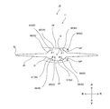
- the non-vertical tail aircraft 10 As shown in FIGS. 1 to 3, the non-vertical tail aircraft 10 according to the embodiment is an airplane such as an all-wing aircraft having no horizontal tail and no vertical tail, and includes a body 11 and a power unit (not shown). ). In the following, a non-vertical tail aircraft without a horizontal tail will be described. However, the non-vertical tail aircraft 10 may have a horizontal tail as long as it does not have a vertical tail.
- the fuselage 11 has a fuselage 20, a main wing 30, and a negative pressure generator 40.
- a direction parallel to the axis 12 of the body 11 extending in the front-rear direction is referred to as an axis direction, and directions perpendicular to the axis direction are referred to as an up-down direction and a left-right direction.
- the direction of the non-vertical tailplane 10 is not limited to this direction.
- the fuselage 20 has a substantially cylindrical shape and extends in the axis direction.
- the fuselage 20 has a front part (front fuselage 21) and a rear part (rear fuselage 50) in the axial direction.
- the dimension of the rear fuselage 50 in the direction of the axis is at least 5% to 60%, more preferably 20% to 50% with respect to the dimension of the fuselage 20.
- the front fuselage 21 has a circular or elliptical cross section perpendicular to the axle 12, and is formed with a curve in the circumferential direction.
- the front fuselage 21 is inclined in a curved shape in the direction of the axis so that the area of the cross section perpendicular to the axis 12 decreases toward the front, and the front end 22 is closed.
- the rear body 50 is, for example, 50% or more with respect to the vertical dimension of the body 20. Further, the rear body 50 has a vertical dimension shorter than a horizontal dimension. However, the rear body 50 may have a vertical dimension that is the same as the horizontal dimension or longer than the horizontal dimension.
- the rear fuselage 50 is squeezed so that the cross-sectional area perpendicular to the axle 12 decreases toward the rear, and the rear end 51 opens as a nozzle outlet of a jet engine that is a power unit of the non-vertical tail aircraft 10. .
- the size of the rear fuselage 50 squeezed toward the rear is longer than the size of the front fuselage 21 squeezed toward the front, for example, over the entire rear fuselage 50.
- the aperture shape may be formed in a part of the rear body 50 and is typically formed in the rear portion including the rear end portion 51 in the rear body 50.
- the top surface 56 and the bottom surface 57 are linearly inclined in the direction of the axis so that the dimension of the rear fuselage 50 in the vertical direction becomes shorter toward the rear.
- the top surface 56 and the bottom surface 57 may be inclined in a curved shape in the axis direction so that the dimension of the rear body 50 in the vertical direction becomes shorter toward the rear.
- the rear body 50 may have a dimension in the left-right direction that is shorter toward the rear so that the cross-sectional area becomes smaller toward the rear.
- the rear body 50 is narrowed toward the rear so that the dimensions of the top surface 56 and the bottom surface 57 in the left-right direction become shorter toward the rear.
- both ends of the top surface 56 and the bottom surface 57 are inclined linearly with respect to the axle 12.
- the inclination angle changes at a predetermined portion 50b at a predetermined distance rearward from the front end 50a connected to the front body 21 in the rear body 50.
- the inclination angle in the rear portion 50d from the predetermined portion 50b to the rear end portion 51 is larger than the inclination angle in the front portion 50c from the front end 50a to the predetermined portion 50b.
- the dimension of the front part 50c is larger than the dimension of the rear part 50d in the machine axis direction.
- the rear body 50 has, for example, a polygonal cross-sectional shape perpendicular to the axle 12, and has an end face 54, a side face 55, and a corner between them.
- the rear body 50 is hexagonal and has two end faces 54 and four side faces 55.
- the two end surfaces 54 are a top surface 56 and a bottom surface 57.
- the four side surfaces 55 are an upper right side surface 58, a lower right side surface 59, an upper left side surface 60 and a lower left side surface 61, and connect the top surface 56 and the bottom surface 57.
- the bottom surface 57 is provided substantially parallel to the top surface 56 and is disposed below the top surface 56.
- the top surface 56 is a flat surface extending linearly in the left-right direction
- the bottom surface 57 is a curved surface extending in a curved shape in the left-right direction so as to be separated from the axle 12.
- the top surface 56 may be a curved surface.
- the bottom surface 57 may be a flat surface. Note that the flat surface may extend linearly in the left-right direction, or may be curved or inclined linearly in the axis direction.
- the upper right side 58 has an upper end connected to the right end of the top surface 56 and a lower end connected to the upper end of the lower right side 59.
- the lower right side 59 has a lower end connected to the right end of the bottom 57. It is connected.
- the upper left side surface 60 has an upper end connected to the left end of the top surface 56 and a lower end connected to the upper end of the lower left side 61.
- the lower left side 61 has a lower end connected to the left end of the bottom 57. ing.
- Each side surface 55 is a flat surface extending linearly in a predetermined direction orthogonal to the machine shaft 12. However, each side surface 55 may be curved in the axis direction or may be inclined linearly.
- each of the upper right side surface 58 and the upper left side surface 60 the dimension between the end connected to the top surface 56 and the end connected to the main wing 30 increases toward the rear in the front portion 50c of the rear fuselage 50, and the rear side
- the rear portion 50d of the body 50 has a shape that becomes smaller toward the rear.
- the dimension between the end connected to the bottom surface 57 and the end connected to the main wing 30 increases toward the rear in the front portion 50c of the rear fuselage 50.
- the rear portion 50d of the body 50 has a shape that becomes smaller toward the rear.
- the corners are an upper right corner 62 between the upper right side 58 and the top surface 56, an upper left corner 63 between the upper left side 60 and the top surface 56, and a lower right corner between the lower right side 59 and the bottom surface 57. 64 and a lower left corner 65 between the lower left side surface 61 and the bottom surface 57.
- the angle ⁇ 1 of the upper right corner portion 62, the angle ⁇ 1 of the upper left corner portion 63, the angle ⁇ 2 of the lower right corner portion 64, and the angle ⁇ 2 of the lower left corner portion 65 are 150 degrees or less from the viewpoint of generating negative pressure. More preferably, the angle is 90 degrees or more and 150 degrees or less.
- the angle of the corner means the inner angle of the corner in the cross section orthogonal to the axis 12 of the rear fuselage 50.
- the main wing 30 is provided on the side surface 55 of the fuselage 20 and extends linearly from the fuselage 20 in the left-right direction.
- the main wing 30 has a shape in which the dimension in the left-right direction increases toward the rear, and is, for example, a substantially triangular delta wing.
- the main wing 30 has a blade root 31 connected to the fuselage 20 and a blade tip 32 farthest from the blade root 31 in the left-right direction.
- the main wing 30 is not limited to a delta wing.
- the leading edge of the main wing 30 between the front end portion 22 and the wing tip 32 is inclined in a substantially straight line so as to move away from the blade root 31 toward the rear in the axial direction, and the wing tip 32 is positioned at a predetermined position of the rear fuselage 50. Extends linearly from the machine axis direction. Further, the rear end of the main wing 30 is formed in a curved shape so that the dimension of the main wing 30 in the axis direction becomes longer as it approaches the blade root 31 from the wing tip 32.
- the blade root 31 is provided from the front fuselage 21 to the rear end of the rear fuselage 50 and extends in the axial direction.
- the blade root 31 is disposed between the upper right side surface 58 and the lower right side surface 59 and between the upper left side surface 60 and the lower left side surface 61 in the vertical direction.
- the negative pressure generating part 40 is a part where a negative pressure NP is generated against a side slip on the side surface 55 of the rear side body 50, and is constituted by, for example, a corner part of the rear side body 50.
- Each corner portion forming the negative pressure generating portion 40 is provided behind the center of gravity of the airframe 11, and the dimension in the axial direction is at least 5% to 60%, more preferably 20%, of the axial direction dimension of the fuselage 20. It is 50% or less.
- the airflow AF flows toward the fuselage 20 in the direction opposite to the flight direction FD.
- the airflow AF indicated by the dotted line in FIG. 3 flows along the top surface 56 in a direction intersecting the axis 12, and peels off at the upper right corner 62.
- a negative pressure NP is generated on the upper right side surface 58 connected to the top surface 56 with the upper right corner 62 interposed therebetween.
- the airflow AF flows along the bottom surface 57 in the direction intersecting the axis 12 and peels off at the lower right corner 64.
- a negative pressure NP is generated on the lower right side surface 59 connected to the bottom surface 57 with the lower right corner 64 interposed therebetween.
- the non-vertical tail aircraft 10 is not provided with a tail, it is possible to reduce the air resistance during flight, the weight, and the cost reduction by reducing the number of parts. .
- the decrease in the stability of the direction due to the absence of the tail can be reduced by the negative pressure generated by the negative pressure generator 40. Further, since the side surface 55 and the top surface 56 are formed as flat surfaces, the negative pressure NP is easily generated, and the decrease in the stability of the direction can be further reduced.
- the angles ⁇ 1 and ⁇ 2 of the corners constituting the negative pressure generating unit 40 are 150 degrees or less, the negative pressure NP is easily generated, and the decrease in the stability of the direction can be further reduced. Further, since the plurality of negative pressure generating portions 40 are provided in the rear body 50 by the four corner portions, it is possible to further reduce the decrease in the direction stability.
- the side surface 55 and the top surface 56 adjacent to the negative pressure generating part 40 for improving the directional stability are constituted by planes, and the productivity is superior compared to those constituted by curved surfaces.
- the rear body 150 includes an end surface 54, a side surface 55, and a corner portion therebetween.
- the end surface 54 has a top surface 56 and a bottom surface 57
- the side surface 55 has a right side surface 156 and a left side surface 157.
- the right side surface 156 has an upper end connected to the right end of the top surface 56 and a lower end connected to the right end of the bottom surface 57.
- the left side surface 157 has an upper end connected to the left end of the top surface 56 and a lower end connected to the left end of the bottom surface 57.
- the blade root 31 is provided at the center in the vertical direction.
- the corners are an upper right corner 162 between the right side 156 and the top surface 56, an upper left corner 163 between the left side 157 and the top surface 56, and a lower right corner 164 between the right side 156 and the bottom surface 57. And a lower left corner 165 between the left side surface 157 and the bottom surface 57.
- the angle ⁇ 3 of the upper right corner 162, the angle ⁇ 3 of the upper left corner 163, the angle ⁇ 4 of the lower right corner 164, and the angle ⁇ 4 of the lower left corner 165 are 90 degrees.
- the top surface 56 is a flat surface extending linearly in the left-right direction
- the right side surface 156 and the left side surface 157 are flat surfaces extending linearly in the up-down direction
- the bottom surface 57 is a curved surface extending in a curved shape in the left-right direction.
- at least one of the top surface 56, the right side surface 156, and the left side surface 157 may be a curved surface.
- the bottom surface 57 may be a flat surface. In the case where these surfaces are formed as flat surfaces, the directional stability by the negative pressure generating unit 40 is superior to the case where these surfaces are formed as curved surfaces.
- the negative pressure generating unit 40 includes an upper right corner 162, an upper left corner 163, a lower right corner 164, and a lower left corner 165.
- the negative pressure NP is generated on the right side surface 156.
- the upper left corner portion 163 and the lower left corner portion 65 are on the downstream side of the airflow AF, a negative pressure NP is generated on the left side surface 157.
- the cross-sectional area of the rear fuselage 150 orthogonal to the machine axis 12 does not change in the machine axis direction and is constant. Even in this case, it is possible to reduce a decrease in direction stability due to the absence of the tail.
- the rear fuselage 150 may be narrowed so that at least one of the dimensions in the up-down direction and the left-right direction becomes shorter toward the rear and the cross-sectional area perpendicular to the axle 12 becomes smaller toward the rear.
- the top body 256 and the bottom surface 257 of the rear fuselage 250 are polygons that are recessed toward the machine shaft 12 side.
- the top surface 256 has a shape bent in two planes at the bent portion 256a
- the bottom surface 257 has a shape bent in two planes at the bent portion 257a.
- the corners 262 and 263 formed between the top surface 256 and the side surface 55 and the corners 264 and 265 formed between the bottom surface 257 and the side surface 55 are connected to the negative pressure generating unit 40.
- the angles ⁇ 21, ⁇ 22 of the corner portions 262, 263, 264, 265 are angles of 60 degrees or more and 150 degrees or less.
- the corners 362 and 363 formed between the top surface 56 and the side surfaces 356 and 357 and the corner portions 364 and 365 formed between the bottom surface 57 and the side surfaces 356 and 357 are negative pressure.
- the generator 40 is configured.
- the angles ⁇ 33 and ⁇ 34 of the corner portions 362, 363, 364, and 365 are angles of 60 degrees or more and 90 degrees or less.
- the rear side body 450 may contain the curve in part in the polygonal cross section orthogonal to the axis 12.
- the top surface 456 is formed by a curved surface that curves so as to be recessed toward the axle 12 side
- the bottom surface 457 is formed by a curved surface that curves so as to be recessed toward the axle 12 side.
- the corner portions 462 and 463 formed between the top surface 456 and the side surface 55 and the corner portions 464 and 465 formed between the bottom surface 457 and the side surface 55 are connected to the negative pressure generating portion 40.
- the angles ⁇ 41, ⁇ 42 of the corner portions 462, 463, 464, 465 are angles of 60 degrees or more and 150 degrees or less.
- the corner portion where the rear body 50 is formed in a polygonal shape is the negative pressure generating portion 40, but is not limited thereto.
- Other configurations may be employed as long as negative pressure is generated on the side of the rear fuselage 50 facing the nose when the aircraft 11 slides.
- the side surfaces 156, 157 of the rear fuselage 550 are recessed toward the axle 12, and the left and right end portions 556a, 556b of the top surface 556 are more than the side surfaces 156, 157. You may form so that it may protrude to the side.
- the end portions 556a and 556b constitute the negative pressure generating unit 40.
- the left and right end portions of the bottom surface 557 are formed so as to protrude from the side surfaces 156 and 157 to the side, and the negative pressure generating portion 40 may be configured. Further, the direction in which the end portions 556a and 556b protrude is not limited to the side, and may be diagonal directions of the upper and upper left and right sides.
- the non-vertical tail aircraft of the present invention is useful as a non-vertical tail aircraft capable of improving directional stability with a simple configuration while suppressing an increase in cost.
- Non-vertical tail aircraft 20 Body 30: Main wing 40: Negative pressure generating part 50: Rear fuselage (rear part) 54: End surface 55: Side surface 56: Top surface 57: Bottom surface 58: Upper right side surface (side surface) 59: lower right side (side) 60: Upper left side surface (side surface) 61: Lower left side (side) 62: Upper right corner (corner) 63: Upper left corner (corner) 64: Lower right corner (corner) 65: Lower left corner (corner) 150: Rear fuselage (rear part) 156: Right side (side) 157: Left side (side) 162: upper right corner (corner) 163: Upper left corner (corner) 164: Lower right corner (corner) 165: Lower left corner (corner) 250: Rear fuselage (rear part) 256: Top surface 257: Bottom surface 262: Upper right corner (corner) 263: Upper left corner (corner) 264: Lower right corner (corner) 265: Lower left corner (corner)
Landscapes
- Engineering & Computer Science (AREA)
- Aviation & Aerospace Engineering (AREA)
- Physics & Mathematics (AREA)
- Fluid Mechanics (AREA)
- Mechanical Engineering (AREA)
- Toys (AREA)
- Structures Of Non-Positive Displacement Pumps (AREA)
Priority Applications (2)
| Application Number | Priority Date | Filing Date | Title |
|---|---|---|---|
| EP19800174.5A EP3792176B1 (en) | 2018-05-10 | 2019-05-08 | Aircraft with no vertical tail |
| US17/092,553 US20210053683A1 (en) | 2018-05-10 | 2020-11-09 | Vertical-tailless aircraft |
Applications Claiming Priority (2)
| Application Number | Priority Date | Filing Date | Title |
|---|---|---|---|
| JP2018-091662 | 2018-05-10 | ||
| JP2018091662A JP7474025B2 (ja) | 2018-05-10 | 2018-05-10 | 無垂直尾翼機 |
Related Child Applications (1)
| Application Number | Title | Priority Date | Filing Date |
|---|---|---|---|
| US17/092,553 Continuation US20210053683A1 (en) | 2018-05-10 | 2020-11-09 | Vertical-tailless aircraft |
Publications (1)
| Publication Number | Publication Date |
|---|---|
| WO2019216350A1 true WO2019216350A1 (ja) | 2019-11-14 |
Family
ID=68467512
Family Applications (1)
| Application Number | Title | Priority Date | Filing Date |
|---|---|---|---|
| PCT/JP2019/018422 Ceased WO2019216350A1 (ja) | 2018-05-10 | 2019-05-08 | 無垂直尾翼機 |
Country Status (4)
| Country | Link |
|---|---|
| US (1) | US20210053683A1 (https=) |
| EP (1) | EP3792176B1 (https=) |
| JP (1) | JP7474025B2 (https=) |
| WO (1) | WO2019216350A1 (https=) |
Families Citing this family (1)
| Publication number | Priority date | Publication date | Assignee | Title |
|---|---|---|---|---|
| RU2758872C1 (ru) * | 2021-05-04 | 2021-11-02 | Федеральное государственное унитарное предприятие "Российский федеральный ядерный центр - Всероссийский научно-исследовательский институт технической физики имени академика Е.И. Забабахина" | Летательный аппарат с повышенной маневренностью |
Citations (5)
| Publication number | Priority date | Publication date | Assignee | Title |
|---|---|---|---|---|
| JPH0495600A (ja) * | 1990-08-13 | 1992-03-27 | Mitsubishi Heavy Ind Ltd | 飛行機体 |
| US5255881A (en) * | 1992-03-25 | 1993-10-26 | Vigyan, Inc. | Lift augmentation for highly swept wing aircraft |
| US5909858A (en) * | 1997-06-19 | 1999-06-08 | Mcdonnell Douglas Corporation | Spanwise transition section for blended wing-body aircraft |
| US6378803B1 (en) * | 1999-12-20 | 2002-04-30 | Manuel Munoz Saiz | Aircraft lift arrangement |
| JP2017019322A (ja) | 2015-07-08 | 2017-01-26 | 株式会社ベルシオン | 無尾翼飛行機 |
Family Cites Families (5)
| Publication number | Priority date | Publication date | Assignee | Title |
|---|---|---|---|---|
| JPH062480B2 (ja) * | 1989-12-08 | 1994-01-12 | 科学技術庁航空宇宙技術研究所長 | 翼端にフィン操舵面を有するデルタ翼構造 |
| US6068219A (en) | 1998-04-13 | 2000-05-30 | Northrop Grumman Corporation | Single surface multi axis aircraft control |
| FR2929591B1 (fr) * | 2008-04-02 | 2010-12-24 | Airbus France | Avion a controle en tangage et en lacet par un ensemble propulsif. |
| DE102010023938A1 (de) * | 2010-06-16 | 2011-12-22 | Eads Deutschland Gmbh | Angetriebenes Fluggerät, insbesondere als Nurflügler und/oder mit geringer Radarsignatur ausgebildetes Fluggerät |
| CN103287576A (zh) | 2013-05-24 | 2013-09-11 | 北京航空航天大学 | 一种无尾布局单人尾坐式垂直起降飞行器 |
-
2018
- 2018-05-10 JP JP2018091662A patent/JP7474025B2/ja active Active
-
2019
- 2019-05-08 EP EP19800174.5A patent/EP3792176B1/en active Active
- 2019-05-08 WO PCT/JP2019/018422 patent/WO2019216350A1/ja not_active Ceased
-
2020
- 2020-11-09 US US17/092,553 patent/US20210053683A1/en not_active Abandoned
Patent Citations (5)
| Publication number | Priority date | Publication date | Assignee | Title |
|---|---|---|---|---|
| JPH0495600A (ja) * | 1990-08-13 | 1992-03-27 | Mitsubishi Heavy Ind Ltd | 飛行機体 |
| US5255881A (en) * | 1992-03-25 | 1993-10-26 | Vigyan, Inc. | Lift augmentation for highly swept wing aircraft |
| US5909858A (en) * | 1997-06-19 | 1999-06-08 | Mcdonnell Douglas Corporation | Spanwise transition section for blended wing-body aircraft |
| US6378803B1 (en) * | 1999-12-20 | 2002-04-30 | Manuel Munoz Saiz | Aircraft lift arrangement |
| JP2017019322A (ja) | 2015-07-08 | 2017-01-26 | 株式会社ベルシオン | 無尾翼飛行機 |
Non-Patent Citations (1)
| Title |
|---|
| See also references of EP3792176A4 |
Also Published As
| Publication number | Publication date |
|---|---|
| JP2019196123A (ja) | 2019-11-14 |
| EP3792176A4 (en) | 2022-01-26 |
| EP3792176B1 (en) | 2023-07-19 |
| US20210053683A1 (en) | 2021-02-25 |
| JP7474025B2 (ja) | 2024-04-24 |
| EP3792176A1 (en) | 2021-03-17 |
Similar Documents
| Publication | Publication Date | Title |
|---|---|---|
| CN107074350B (zh) | 一种用于飞行器的机翼以及包括这种机翼的飞行器 | |
| CN104144853B (zh) | 机翼的翼尖装置和具有这种翼尖装置的机翼 | |
| EP3031713B1 (en) | Aircraft wing rib | |
| KR101723666B1 (ko) | 진보된 피치 스태빌라이저를 갖는 회전날개 항공기 | |
| EP3269635A1 (en) | Airplane wing | |
| CN101896401A (zh) | 用于减小飞机的尾涡的翼尖延长部 | |
| US9789955B1 (en) | High-lift device of air vehicle | |
| CN107428410A (zh) | 与机身集成的螺旋桨驱动的推进系统 | |
| JP7608063B2 (ja) | 飛行体 | |
| US8827201B2 (en) | Rotorcraft structural element for reducing aerodynamic drag | |
| JP2011513118A (ja) | ショックバンプアレイ | |
| CN106741922A (zh) | 一种基于后掠桨尖开孔的旋翼噪声抑制方法 | |
| KR102279988B1 (ko) | 스테빌라이저 윙이 있는 회전익기 | |
| CN106184710B (zh) | 飞机机翼的翼尖装置 | |
| KR101888593B1 (ko) | 꼬리 덮개를 지닌 회전익 항공기 | |
| US10562606B2 (en) | Wing, flap, and aircraft | |
| US20190161164A1 (en) | Hybrid type rotorcraft having a horizontal stabilizer and two fins arranged on the horizontal stabilizer | |
| WO2019216350A1 (ja) | 無垂直尾翼機 | |
| CN102762454A (zh) | 用于飞行器的空气动力学辅助面的装置 | |
| US11858622B2 (en) | Aircraft | |
| US9242713B2 (en) | Aerodynamic, blunt aft body | |
| CN115298091B (zh) | 直升机、直升机套件及相关联的重新配置方法 | |
| JP2005335621A (ja) | ヘリコプタのロータブレード | |
| US20240174354A1 (en) | A rotorcraft with a tail boom and an integral stabilizer arrangement | |
| CN121716885A (zh) | 翼梢小翼 |
Legal Events
| Date | Code | Title | Description |
|---|---|---|---|
| 121 | Ep: the epo has been informed by wipo that ep was designated in this application |
Ref document number: 19800174 Country of ref document: EP Kind code of ref document: A1 |
|
| NENP | Non-entry into the national phase |
Ref country code: DE |
|
| WWE | Wipo information: entry into national phase |
Ref document number: 2019800174 Country of ref document: EP |
|
| ENP | Entry into the national phase |
Ref document number: 2019800174 Country of ref document: EP Effective date: 20201210 |