WO2019216350A1 - Aircraft with no vertical tail - Google Patents
Aircraft with no vertical tail Download PDFInfo
- Publication number
- WO2019216350A1 WO2019216350A1 PCT/JP2019/018422 JP2019018422W WO2019216350A1 WO 2019216350 A1 WO2019216350 A1 WO 2019216350A1 JP 2019018422 W JP2019018422 W JP 2019018422W WO 2019216350 A1 WO2019216350 A1 WO 2019216350A1
- Authority
- WO
- WIPO (PCT)
- Prior art keywords
- fuselage
- corner
- negative pressure
- vertical tail
- aircraft
- Prior art date
Links
- 230000007423 decrease Effects 0.000 claims description 11
- 230000004048 modification Effects 0.000 description 4
- 238000012986 modification Methods 0.000 description 4
- 238000013459 approach Methods 0.000 description 2
- 230000003247 decreasing effect Effects 0.000 description 1
- 230000000694 effects Effects 0.000 description 1
- 230000005484 gravity Effects 0.000 description 1
- 238000004519 manufacturing process Methods 0.000 description 1
Images


Classifications
-
- B—PERFORMING OPERATIONS; TRANSPORTING
- B64—AIRCRAFT; AVIATION; COSMONAUTICS
- B64C—AEROPLANES; HELICOPTERS
- B64C5/00—Stabilising surfaces
-
- B—PERFORMING OPERATIONS; TRANSPORTING
- B64—AIRCRAFT; AVIATION; COSMONAUTICS
- B64C—AEROPLANES; HELICOPTERS
- B64C1/00—Fuselages; Constructional features common to fuselages, wings, stabilising surfaces or the like
- B64C1/0009—Aerodynamic aspects
-
- B—PERFORMING OPERATIONS; TRANSPORTING
- B64—AIRCRAFT; AVIATION; COSMONAUTICS
- B64C—AEROPLANES; HELICOPTERS
- B64C39/00—Aircraft not otherwise provided for
- B64C39/10—All-wing aircraft
-
- B—PERFORMING OPERATIONS; TRANSPORTING
- B64—AIRCRAFT; AVIATION; COSMONAUTICS
- B64C—AEROPLANES; HELICOPTERS
- B64C7/00—Structures or fairings not otherwise provided for
-
- B—PERFORMING OPERATIONS; TRANSPORTING
- B64—AIRCRAFT; AVIATION; COSMONAUTICS
- B64C—AEROPLANES; HELICOPTERS
- B64C39/00—Aircraft not otherwise provided for
- B64C39/10—All-wing aircraft
- B64C2039/105—All-wing aircraft of blended wing body type
-
- B—PERFORMING OPERATIONS; TRANSPORTING
- B64—AIRCRAFT; AVIATION; COSMONAUTICS
- B64C—AEROPLANES; HELICOPTERS
- B64C2230/00—Boundary layer controls
- B64C2230/20—Boundary layer controls by passively inducing fluid flow, e.g. by means of a pressure difference between both ends of a slot or duct
Definitions
- the present invention relates to a non-vertical tail aircraft that is an aircraft that does not have a vertical tail.
- the no-tail aircraft of Patent Document 1 As a conventional non-vertical tail aircraft that does not have a vertical tail, the no-tail aircraft of Patent Document 1 is known.
- the body of this tailless airplane has a left trunk and a right trunk that project obliquely from the side of the main trunk to the left and right rear outside.
- An elevator is disposed at the rear end of each of the left and right trunks.
- the tailless airplane of Patent Document 1 improves directional stability by utilizing the difference in velocity between the airflow flowing on the upper surface of the aircraft and the airflow flowing on the lower surface during a skid. For this reason, it is necessary to make the upper surface and lower surface of an airframe into a curvilinear shape, and it cannot be said that manufacturing cost is low.
- the present invention has been made to solve such a problem, and an object thereof is to provide a non-vertical tail aircraft capable of improving directional stability with a simple configuration while suppressing an increase in cost.
- a non-vertical tail aircraft includes a fuselage extending in an axial direction, a main wing provided on a side surface of the fuselage, and a negative pressure that generates a negative pressure on a side surface at a rear portion of the fuselage against a side slip.
- a generator is
- the present invention has the configuration described above, and has an effect that it is possible to provide a non-vertical tail aircraft that can improve directional stability with a simple configuration while suppressing an increase in cost.
- FIG. 2 is a cross-sectional view of a non-vertical tail machine cut along line A-A ′ in FIG. 1. It is sectional drawing which shows the non-vertical tail aircraft which concerns on the modification of embodiment.
- FIG. 5A and FIG. 5B are cross-sectional views showing a non-vertical tail aircraft according to another modification of the embodiment.
- FIG. 6A and FIG. 6B are cross-sectional views showing a non-vertical tail aircraft according to another modification of the embodiment.
- a non-vertical tail aircraft includes a fuselage extending in an axial direction, a main wing provided on a side surface of the fuselage, and a negative pressure generating unit that generates a negative pressure on a side surface of a rear portion of the fuselage against a side slip. It is equipped with.
- the rear portion of the fuselage may have a corner portion formed between the top surface or the bottom surface and the side surface, and the negative pressure generating portion may be the corner portion.
- angular part a negative pressure is efficiently generated on a side surface, and direction stability can be improved.
- the negative pressure generating part is formed here by providing the rear corner part, the structure can be simplified and the increase in cost can be suppressed.
- the inner angle of the corner in the cross section perpendicular to the axis of the rear of the fuselage may be 60 degrees or more and 150 degrees or less. According to this configuration, negative pressure is efficiently generated at the corners of such an angle, and the directional stability can be improved.
- the rear part of the fuselage may have a polygonal cross section perpendicular to the axis. According to this configuration, the negative pressure is efficiently generated in the negative pressure generating section, and the directional stability can be improved. Further, since the negative pressure generating portion is formed by the shape of the rear portion, the configuration can be simplified and the cost increase can be suppressed.
- the rear part of the fuselage may have a shape in which the cross-sectional area perpendicular to the aircraft axis decreases toward the rear. According to this configuration, the negative pressure is more efficiently generated in the negative pressure generating section, and the directional stability can be improved.
- At least one of the top and bottom surfaces of the rear of the fuselage may be a flat surface. According to this configuration, since the airflow flowing along the top and / or bottom of the flat surface is easily separated at the corners, the directional stability can be improved by the negative pressure generated thereby.
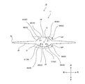
- the non-vertical tail aircraft 10 As shown in FIGS. 1 to 3, the non-vertical tail aircraft 10 according to the embodiment is an airplane such as an all-wing aircraft having no horizontal tail and no vertical tail, and includes a body 11 and a power unit (not shown). ). In the following, a non-vertical tail aircraft without a horizontal tail will be described. However, the non-vertical tail aircraft 10 may have a horizontal tail as long as it does not have a vertical tail.
- the fuselage 11 has a fuselage 20, a main wing 30, and a negative pressure generator 40.
- a direction parallel to the axis 12 of the body 11 extending in the front-rear direction is referred to as an axis direction, and directions perpendicular to the axis direction are referred to as an up-down direction and a left-right direction.
- the direction of the non-vertical tailplane 10 is not limited to this direction.
- the fuselage 20 has a substantially cylindrical shape and extends in the axis direction.
- the fuselage 20 has a front part (front fuselage 21) and a rear part (rear fuselage 50) in the axial direction.
- the dimension of the rear fuselage 50 in the direction of the axis is at least 5% to 60%, more preferably 20% to 50% with respect to the dimension of the fuselage 20.
- the front fuselage 21 has a circular or elliptical cross section perpendicular to the axle 12, and is formed with a curve in the circumferential direction.
- the front fuselage 21 is inclined in a curved shape in the direction of the axis so that the area of the cross section perpendicular to the axis 12 decreases toward the front, and the front end 22 is closed.
- the rear body 50 is, for example, 50% or more with respect to the vertical dimension of the body 20. Further, the rear body 50 has a vertical dimension shorter than a horizontal dimension. However, the rear body 50 may have a vertical dimension that is the same as the horizontal dimension or longer than the horizontal dimension.
- the rear fuselage 50 is squeezed so that the cross-sectional area perpendicular to the axle 12 decreases toward the rear, and the rear end 51 opens as a nozzle outlet of a jet engine that is a power unit of the non-vertical tail aircraft 10. .
- the size of the rear fuselage 50 squeezed toward the rear is longer than the size of the front fuselage 21 squeezed toward the front, for example, over the entire rear fuselage 50.
- the aperture shape may be formed in a part of the rear body 50 and is typically formed in the rear portion including the rear end portion 51 in the rear body 50.
- the top surface 56 and the bottom surface 57 are linearly inclined in the direction of the axis so that the dimension of the rear fuselage 50 in the vertical direction becomes shorter toward the rear.
- the top surface 56 and the bottom surface 57 may be inclined in a curved shape in the axis direction so that the dimension of the rear body 50 in the vertical direction becomes shorter toward the rear.
- the rear body 50 may have a dimension in the left-right direction that is shorter toward the rear so that the cross-sectional area becomes smaller toward the rear.
- the rear body 50 is narrowed toward the rear so that the dimensions of the top surface 56 and the bottom surface 57 in the left-right direction become shorter toward the rear.
- both ends of the top surface 56 and the bottom surface 57 are inclined linearly with respect to the axle 12.
- the inclination angle changes at a predetermined portion 50b at a predetermined distance rearward from the front end 50a connected to the front body 21 in the rear body 50.
- the inclination angle in the rear portion 50d from the predetermined portion 50b to the rear end portion 51 is larger than the inclination angle in the front portion 50c from the front end 50a to the predetermined portion 50b.
- the dimension of the front part 50c is larger than the dimension of the rear part 50d in the machine axis direction.
- the rear body 50 has, for example, a polygonal cross-sectional shape perpendicular to the axle 12, and has an end face 54, a side face 55, and a corner between them.
- the rear body 50 is hexagonal and has two end faces 54 and four side faces 55.
- the two end surfaces 54 are a top surface 56 and a bottom surface 57.
- the four side surfaces 55 are an upper right side surface 58, a lower right side surface 59, an upper left side surface 60 and a lower left side surface 61, and connect the top surface 56 and the bottom surface 57.
- the bottom surface 57 is provided substantially parallel to the top surface 56 and is disposed below the top surface 56.
- the top surface 56 is a flat surface extending linearly in the left-right direction
- the bottom surface 57 is a curved surface extending in a curved shape in the left-right direction so as to be separated from the axle 12.
- the top surface 56 may be a curved surface.
- the bottom surface 57 may be a flat surface. Note that the flat surface may extend linearly in the left-right direction, or may be curved or inclined linearly in the axis direction.
- the upper right side 58 has an upper end connected to the right end of the top surface 56 and a lower end connected to the upper end of the lower right side 59.
- the lower right side 59 has a lower end connected to the right end of the bottom 57. It is connected.
- the upper left side surface 60 has an upper end connected to the left end of the top surface 56 and a lower end connected to the upper end of the lower left side 61.
- the lower left side 61 has a lower end connected to the left end of the bottom 57. ing.
- Each side surface 55 is a flat surface extending linearly in a predetermined direction orthogonal to the machine shaft 12. However, each side surface 55 may be curved in the axis direction or may be inclined linearly.
- each of the upper right side surface 58 and the upper left side surface 60 the dimension between the end connected to the top surface 56 and the end connected to the main wing 30 increases toward the rear in the front portion 50c of the rear fuselage 50, and the rear side
- the rear portion 50d of the body 50 has a shape that becomes smaller toward the rear.
- the dimension between the end connected to the bottom surface 57 and the end connected to the main wing 30 increases toward the rear in the front portion 50c of the rear fuselage 50.
- the rear portion 50d of the body 50 has a shape that becomes smaller toward the rear.
- the corners are an upper right corner 62 between the upper right side 58 and the top surface 56, an upper left corner 63 between the upper left side 60 and the top surface 56, and a lower right corner between the lower right side 59 and the bottom surface 57. 64 and a lower left corner 65 between the lower left side surface 61 and the bottom surface 57.
- the angle ⁇ 1 of the upper right corner portion 62, the angle ⁇ 1 of the upper left corner portion 63, the angle ⁇ 2 of the lower right corner portion 64, and the angle ⁇ 2 of the lower left corner portion 65 are 150 degrees or less from the viewpoint of generating negative pressure. More preferably, the angle is 90 degrees or more and 150 degrees or less.
- the angle of the corner means the inner angle of the corner in the cross section orthogonal to the axis 12 of the rear fuselage 50.
- the main wing 30 is provided on the side surface 55 of the fuselage 20 and extends linearly from the fuselage 20 in the left-right direction.
- the main wing 30 has a shape in which the dimension in the left-right direction increases toward the rear, and is, for example, a substantially triangular delta wing.
- the main wing 30 has a blade root 31 connected to the fuselage 20 and a blade tip 32 farthest from the blade root 31 in the left-right direction.
- the main wing 30 is not limited to a delta wing.
- the leading edge of the main wing 30 between the front end portion 22 and the wing tip 32 is inclined in a substantially straight line so as to move away from the blade root 31 toward the rear in the axial direction, and the wing tip 32 is positioned at a predetermined position of the rear fuselage 50. Extends linearly from the machine axis direction. Further, the rear end of the main wing 30 is formed in a curved shape so that the dimension of the main wing 30 in the axis direction becomes longer as it approaches the blade root 31 from the wing tip 32.
- the blade root 31 is provided from the front fuselage 21 to the rear end of the rear fuselage 50 and extends in the axial direction.
- the blade root 31 is disposed between the upper right side surface 58 and the lower right side surface 59 and between the upper left side surface 60 and the lower left side surface 61 in the vertical direction.
- the negative pressure generating part 40 is a part where a negative pressure NP is generated against a side slip on the side surface 55 of the rear side body 50, and is constituted by, for example, a corner part of the rear side body 50.
- Each corner portion forming the negative pressure generating portion 40 is provided behind the center of gravity of the airframe 11, and the dimension in the axial direction is at least 5% to 60%, more preferably 20%, of the axial direction dimension of the fuselage 20. It is 50% or less.
- the airflow AF flows toward the fuselage 20 in the direction opposite to the flight direction FD.
- the airflow AF indicated by the dotted line in FIG. 3 flows along the top surface 56 in a direction intersecting the axis 12, and peels off at the upper right corner 62.
- a negative pressure NP is generated on the upper right side surface 58 connected to the top surface 56 with the upper right corner 62 interposed therebetween.
- the airflow AF flows along the bottom surface 57 in the direction intersecting the axis 12 and peels off at the lower right corner 64.
- a negative pressure NP is generated on the lower right side surface 59 connected to the bottom surface 57 with the lower right corner 64 interposed therebetween.
- the non-vertical tail aircraft 10 is not provided with a tail, it is possible to reduce the air resistance during flight, the weight, and the cost reduction by reducing the number of parts. .
- the decrease in the stability of the direction due to the absence of the tail can be reduced by the negative pressure generated by the negative pressure generator 40. Further, since the side surface 55 and the top surface 56 are formed as flat surfaces, the negative pressure NP is easily generated, and the decrease in the stability of the direction can be further reduced.
- the angles ⁇ 1 and ⁇ 2 of the corners constituting the negative pressure generating unit 40 are 150 degrees or less, the negative pressure NP is easily generated, and the decrease in the stability of the direction can be further reduced. Further, since the plurality of negative pressure generating portions 40 are provided in the rear body 50 by the four corner portions, it is possible to further reduce the decrease in the direction stability.
- the side surface 55 and the top surface 56 adjacent to the negative pressure generating part 40 for improving the directional stability are constituted by planes, and the productivity is superior compared to those constituted by curved surfaces.
- the rear body 150 includes an end surface 54, a side surface 55, and a corner portion therebetween.
- the end surface 54 has a top surface 56 and a bottom surface 57
- the side surface 55 has a right side surface 156 and a left side surface 157.
- the right side surface 156 has an upper end connected to the right end of the top surface 56 and a lower end connected to the right end of the bottom surface 57.
- the left side surface 157 has an upper end connected to the left end of the top surface 56 and a lower end connected to the left end of the bottom surface 57.
- the blade root 31 is provided at the center in the vertical direction.
- the corners are an upper right corner 162 between the right side 156 and the top surface 56, an upper left corner 163 between the left side 157 and the top surface 56, and a lower right corner 164 between the right side 156 and the bottom surface 57. And a lower left corner 165 between the left side surface 157 and the bottom surface 57.
- the angle ⁇ 3 of the upper right corner 162, the angle ⁇ 3 of the upper left corner 163, the angle ⁇ 4 of the lower right corner 164, and the angle ⁇ 4 of the lower left corner 165 are 90 degrees.
- the top surface 56 is a flat surface extending linearly in the left-right direction
- the right side surface 156 and the left side surface 157 are flat surfaces extending linearly in the up-down direction
- the bottom surface 57 is a curved surface extending in a curved shape in the left-right direction.
- at least one of the top surface 56, the right side surface 156, and the left side surface 157 may be a curved surface.
- the bottom surface 57 may be a flat surface. In the case where these surfaces are formed as flat surfaces, the directional stability by the negative pressure generating unit 40 is superior to the case where these surfaces are formed as curved surfaces.
- the negative pressure generating unit 40 includes an upper right corner 162, an upper left corner 163, a lower right corner 164, and a lower left corner 165.
- the negative pressure NP is generated on the right side surface 156.
- the upper left corner portion 163 and the lower left corner portion 65 are on the downstream side of the airflow AF, a negative pressure NP is generated on the left side surface 157.
- the cross-sectional area of the rear fuselage 150 orthogonal to the machine axis 12 does not change in the machine axis direction and is constant. Even in this case, it is possible to reduce a decrease in direction stability due to the absence of the tail.
- the rear fuselage 150 may be narrowed so that at least one of the dimensions in the up-down direction and the left-right direction becomes shorter toward the rear and the cross-sectional area perpendicular to the axle 12 becomes smaller toward the rear.
- the top body 256 and the bottom surface 257 of the rear fuselage 250 are polygons that are recessed toward the machine shaft 12 side.
- the top surface 256 has a shape bent in two planes at the bent portion 256a
- the bottom surface 257 has a shape bent in two planes at the bent portion 257a.
- the corners 262 and 263 formed between the top surface 256 and the side surface 55 and the corners 264 and 265 formed between the bottom surface 257 and the side surface 55 are connected to the negative pressure generating unit 40.
- the angles ⁇ 21, ⁇ 22 of the corner portions 262, 263, 264, 265 are angles of 60 degrees or more and 150 degrees or less.
- the corners 362 and 363 formed between the top surface 56 and the side surfaces 356 and 357 and the corner portions 364 and 365 formed between the bottom surface 57 and the side surfaces 356 and 357 are negative pressure.
- the generator 40 is configured.
- the angles ⁇ 33 and ⁇ 34 of the corner portions 362, 363, 364, and 365 are angles of 60 degrees or more and 90 degrees or less.
- the rear side body 450 may contain the curve in part in the polygonal cross section orthogonal to the axis 12.
- the top surface 456 is formed by a curved surface that curves so as to be recessed toward the axle 12 side
- the bottom surface 457 is formed by a curved surface that curves so as to be recessed toward the axle 12 side.
- the corner portions 462 and 463 formed between the top surface 456 and the side surface 55 and the corner portions 464 and 465 formed between the bottom surface 457 and the side surface 55 are connected to the negative pressure generating portion 40.
- the angles ⁇ 41, ⁇ 42 of the corner portions 462, 463, 464, 465 are angles of 60 degrees or more and 150 degrees or less.
- the corner portion where the rear body 50 is formed in a polygonal shape is the negative pressure generating portion 40, but is not limited thereto.
- Other configurations may be employed as long as negative pressure is generated on the side of the rear fuselage 50 facing the nose when the aircraft 11 slides.
- the side surfaces 156, 157 of the rear fuselage 550 are recessed toward the axle 12, and the left and right end portions 556a, 556b of the top surface 556 are more than the side surfaces 156, 157. You may form so that it may protrude to the side.
- the end portions 556a and 556b constitute the negative pressure generating unit 40.
- the left and right end portions of the bottom surface 557 are formed so as to protrude from the side surfaces 156 and 157 to the side, and the negative pressure generating portion 40 may be configured. Further, the direction in which the end portions 556a and 556b protrude is not limited to the side, and may be diagonal directions of the upper and upper left and right sides.
- the non-vertical tail aircraft of the present invention is useful as a non-vertical tail aircraft capable of improving directional stability with a simple configuration while suppressing an increase in cost.
- Non-vertical tail aircraft 20 Body 30: Main wing 40: Negative pressure generating part 50: Rear fuselage (rear part) 54: End surface 55: Side surface 56: Top surface 57: Bottom surface 58: Upper right side surface (side surface) 59: lower right side (side) 60: Upper left side surface (side surface) 61: Lower left side (side) 62: Upper right corner (corner) 63: Upper left corner (corner) 64: Lower right corner (corner) 65: Lower left corner (corner) 150: Rear fuselage (rear part) 156: Right side (side) 157: Left side (side) 162: upper right corner (corner) 163: Upper left corner (corner) 164: Lower right corner (corner) 165: Lower left corner (corner) 250: Rear fuselage (rear part) 256: Top surface 257: Bottom surface 262: Upper right corner (corner) 263: Upper left corner (corner) 264: Lower right corner (corner) 265: Lower left corner (corner)
Landscapes
- Engineering & Computer Science (AREA)
- Aviation & Aerospace Engineering (AREA)
- Physics & Mathematics (AREA)
- Fluid Mechanics (AREA)
- Mechanical Engineering (AREA)
- Toys (AREA)
- Structures Of Non-Positive Displacement Pumps (AREA)
Abstract
An aircraft (10) with no vertical tail is provided with: a fuselage (20) extending in the aircraft axis direction; primary wings (30) provided to lateral surfaces (55) of the fuselage (20); and a negative pressure generating section (40) for generating negative pressure over the lateral surfaces (55) at the rear of the fuselage (20) with respect to sideslip.
Description
本発明は、垂直尾翼を備えない航空機である無垂直尾翼機に関する。
The present invention relates to a non-vertical tail aircraft that is an aircraft that does not have a vertical tail.
垂直尾翼を備えない従来の無垂直尾翼機として、特許文献1の無尾翼飛行機が知られている。この無尾翼飛行機の機体は、主胴部の側面から左右の後外側へ斜めに突出する左側胴部及び右側胴部を有している。この左側胴部及び右側胴部のそれぞれの後端部に昇降舵が配設されている。
As a conventional non-vertical tail aircraft that does not have a vertical tail, the no-tail aircraft of Patent Document 1 is known. The body of this tailless airplane has a left trunk and a right trunk that project obliquely from the side of the main trunk to the left and right rear outside. An elevator is disposed at the rear end of each of the left and right trunks.
上記特許文献1の無尾翼飛行機では、横滑り時に機体の上面を流れる気流と下面を流れる気流との速度差を利用して、方向安定性を向上させている。このため、機体の上面及び下面を曲線的な形状とする必要があり、製造コストが低いとは言い難い。
The tailless airplane of Patent Document 1 improves directional stability by utilizing the difference in velocity between the airflow flowing on the upper surface of the aircraft and the airflow flowing on the lower surface during a skid. For this reason, it is necessary to make the upper surface and lower surface of an airframe into a curvilinear shape, and it cannot be said that manufacturing cost is low.
本発明はこのような課題を解決するためになされたものであり、コスト上昇を抑えながら、簡易な構成により方向安定性を向上することができる無垂直尾翼機を提供することを目的としている。
The present invention has been made to solve such a problem, and an object thereof is to provide a non-vertical tail aircraft capable of improving directional stability with a simple configuration while suppressing an increase in cost.
本発明のある態様に係る無垂直尾翼機は、機軸方向に延びる胴体と、前記胴体の側面に設けられた主翼と、横滑りに対して前記胴体の後部における側面上に負圧を発生させる負圧発生部と、を備えている。
A non-vertical tail aircraft according to an aspect of the present invention includes a fuselage extending in an axial direction, a main wing provided on a side surface of the fuselage, and a negative pressure that generates a negative pressure on a side surface at a rear portion of the fuselage against a side slip. A generator.
この構成によれば、側面上に発生した負圧によって横滑りによる機軸と飛行方向とのズレを減少する方向に力が発生する。このため、コスト上昇を抑えながら、簡易な構成により方向安定性を向上することができる。
れ ば According to this configuration, a force is generated in a direction that reduces the deviation between the axis and the flight direction due to skidding due to the negative pressure generated on the side surface. For this reason, it is possible to improve the directional stability with a simple configuration while suppressing an increase in cost.
本発明は、以上に説明した構成を有し、コスト上昇を抑えながら、簡易な構成により方向安定性を向上することができる無垂直尾翼機を提供することができるという効果を奏する。
The present invention has the configuration described above, and has an effect that it is possible to provide a non-vertical tail aircraft that can improve directional stability with a simple configuration while suppressing an increase in cost.
本発明の上記目的、他の目的、特徴、及び利点は、添付図面参照の下、以下の好適な実施態様の詳細な説明から明らかにされる。
The above object, other objects, features, and advantages of the present invention will become apparent from the following detailed description of preferred embodiments with reference to the accompanying drawings.
ある態様に係る無垂直尾翼機は、機軸方向に延びる胴体と、前記胴体の側面に設けられた主翼と、横滑りに対して前記胴体の後部における側面上に負圧を発生させる負圧発生部と、を備えている。
A non-vertical tail aircraft according to an aspect includes a fuselage extending in an axial direction, a main wing provided on a side surface of the fuselage, and a negative pressure generating unit that generates a negative pressure on a side surface of a rear portion of the fuselage against a side slip. It is equipped with.
この構成によれば、側面上に発生した負圧によって横滑りによる機軸と飛行方向とのズレを減少する方向に力が発生する。このため、コスト上昇を抑えながら、簡易な構成により方向安定性を向上することができる。
れ ば According to this configuration, a force is generated in a direction that reduces the deviation between the axis and the flight direction due to skidding due to the negative pressure generated on the side surface. For this reason, it is possible to improve the directional stability with a simple configuration while suppressing an increase in cost.
この無垂直尾翼機では、前記胴体の後部は、天面又は底面と前記側面との間に形成された角部を有し、前記負圧発生部は前記角部であってもよい。この構成によれば、横滑りにより端面に沿って流れる気流が角部において剥離し、側面上に負圧が効率的に発生し、方向安定性を向上することができる。また、後部の角部を設けることによりここに負圧発生部が形成されるため、構成の簡易化及びコスト上昇の抑制を図ることができる。
In this non-vertical tailplane, the rear portion of the fuselage may have a corner portion formed between the top surface or the bottom surface and the side surface, and the negative pressure generating portion may be the corner portion. According to this structure, the airflow which flows along an end surface by side slip peels in a corner | angular part, a negative pressure is efficiently generated on a side surface, and direction stability can be improved. Moreover, since the negative pressure generating part is formed here by providing the rear corner part, the structure can be simplified and the increase in cost can be suppressed.
この無垂直尾翼機では、前記胴体の後部の前記機軸に直交する断面における前記角部の内角が60度以上150度以下であってもよい。この構成によれば、このような角度の角部において負圧が効率的に発生し、方向安定性を向上することができる。
In this non-vertical tail aircraft, the inner angle of the corner in the cross section perpendicular to the axis of the rear of the fuselage may be 60 degrees or more and 150 degrees or less. According to this configuration, negative pressure is efficiently generated at the corners of such an angle, and the directional stability can be improved.
この無垂直尾翼機では、前記胴体の後部は、前記機軸に直交する断面が多角形であってもよい。この構成によれば、負圧発生部において負圧が効率的に発生し、方向安定性を向上することができる。また、後部の形状により負圧発生部が形成されるため、構成の簡易化及びコスト上昇の抑制を図ることができる。
In this non-vertical tail aircraft, the rear part of the fuselage may have a polygonal cross section perpendicular to the axis. According to this configuration, the negative pressure is efficiently generated in the negative pressure generating section, and the directional stability can be improved. Further, since the negative pressure generating portion is formed by the shape of the rear portion, the configuration can be simplified and the cost increase can be suppressed.
この無垂直尾翼機では、前記胴体の後部は、前記機軸に直交する断面の面積が後方ほど小さくなる形状を有していてもよい。この構成によれば、負圧発生部においてより効率的に負圧が発生し方向安定性を向上することができる。
In this non-vertical tail aircraft, the rear part of the fuselage may have a shape in which the cross-sectional area perpendicular to the aircraft axis decreases toward the rear. According to this configuration, the negative pressure is more efficiently generated in the negative pressure generating section, and the directional stability can be improved.
この無垂直尾翼機では、前記胴体の後部の天面及び底面の少なくともいずれか一方の面が平坦面であってもよい。この構成によれば、平坦面の天面及び/又は底面に沿って流れる気流が角部において剥離し易いため、これにより発生する負圧によって方向安定性を向上することができる。
In this non-vertical tailplane, at least one of the top and bottom surfaces of the rear of the fuselage may be a flat surface. According to this configuration, since the airflow flowing along the top and / or bottom of the flat surface is easily separated at the corners, the directional stability can be improved by the negative pressure generated thereby.
以下、実施の形態を、図面を参照しながら具体的に説明する。なお、以下では全ての図面を通じて同一又は相当する要素には同一の参照符号を付して、その重複する説明を省略する。
Hereinafter, embodiments will be specifically described with reference to the drawings. In the following description, the same or corresponding elements are denoted by the same reference symbols throughout all the drawings, and redundant description thereof is omitted.
(実施の形態)
実施の形態に係る無垂直尾翼機10は、図1~図3に示すように、水平尾翼及び垂直尾翼を有さない全翼機等の飛行機であって、機体11及び動力装置(図示せず)を備えている。なお、以下では、水平尾翼を有さない無垂直尾翼機について説明するが、無垂直尾翼機10は垂直尾翼を有していなければ水平尾翼を有していてもよい。 (Embodiment)
As shown in FIGS. 1 to 3, thenon-vertical tail aircraft 10 according to the embodiment is an airplane such as an all-wing aircraft having no horizontal tail and no vertical tail, and includes a body 11 and a power unit (not shown). ). In the following, a non-vertical tail aircraft without a horizontal tail will be described. However, the non-vertical tail aircraft 10 may have a horizontal tail as long as it does not have a vertical tail.
実施の形態に係る無垂直尾翼機10は、図1~図3に示すように、水平尾翼及び垂直尾翼を有さない全翼機等の飛行機であって、機体11及び動力装置(図示せず)を備えている。なお、以下では、水平尾翼を有さない無垂直尾翼機について説明するが、無垂直尾翼機10は垂直尾翼を有していなければ水平尾翼を有していてもよい。 (Embodiment)
As shown in FIGS. 1 to 3, the
機体11は、胴体20、主翼30及び負圧発生部40を有している。なお、前後方向に延びる機体11の機軸12に平行な方向を機軸方向と称し、機軸方向に対して互いに直交する方向を上下方向及び左右方向と称する。ただし、無垂直尾翼機10の向きはこの方向に限定されない。
The fuselage 11 has a fuselage 20, a main wing 30, and a negative pressure generator 40. A direction parallel to the axis 12 of the body 11 extending in the front-rear direction is referred to as an axis direction, and directions perpendicular to the axis direction are referred to as an up-down direction and a left-right direction. However, the direction of the non-vertical tailplane 10 is not limited to this direction.
胴体20は、略筒形状であって、機軸方向に延びている。胴体20は、機軸方向において、前部(前側胴体21)及び後部(後側胴体50)を有している。機軸方向における後側胴体50の寸法は、胴体20の寸法に対して少なくとも5%以上60%以下であり、より好ましくは20%以上50%以下である。
The fuselage 20 has a substantially cylindrical shape and extends in the axis direction. The fuselage 20 has a front part (front fuselage 21) and a rear part (rear fuselage 50) in the axial direction. The dimension of the rear fuselage 50 in the direction of the axis is at least 5% to 60%, more preferably 20% to 50% with respect to the dimension of the fuselage 20.
前側胴体21は、機軸12に直交する断面が円形状又は楕円形状であって、周方向において曲線で形成されている。前側胴体21は、機軸12に直交する断面の面積が前方ほど小さくなるように機軸方向において曲線状に傾斜し、前端部22が閉じている。
The front fuselage 21 has a circular or elliptical cross section perpendicular to the axle 12, and is formed with a curve in the circumferential direction. The front fuselage 21 is inclined in a curved shape in the direction of the axis so that the area of the cross section perpendicular to the axis 12 decreases toward the front, and the front end 22 is closed.
後側胴体50は、例えば、胴体20の上下方向の寸法に対して50%以上である。また、後側胴体50は、上下方向の寸法が左右方向の寸法よりも短い。ただし、後側胴体50は、上下方向の寸法が左右方向の寸法と同じ又は左右方向の寸法より長くてもよい。
The rear body 50 is, for example, 50% or more with respect to the vertical dimension of the body 20. Further, the rear body 50 has a vertical dimension shorter than a horizontal dimension. However, the rear body 50 may have a vertical dimension that is the same as the horizontal dimension or longer than the horizontal dimension.
後側胴体50は、機軸12に直交する断面の面積が後方ほど小さくなるように絞られ、後端部51は、無垂直尾翼機10の動力装置であるジェットエンジンのノズル出口として開口している。機軸方向において、後方ほど絞られる後側胴体50の寸法は、前方ほど絞られる前側胴体21の寸法よりも長く、例えば、後側胴体50の全体に亘っている。ただし、この絞り形状は後側胴体50の一部に形成されていてもよく、典型的には後側胴体50において後端部51を含む後部に形成する。
The rear fuselage 50 is squeezed so that the cross-sectional area perpendicular to the axle 12 decreases toward the rear, and the rear end 51 opens as a nozzle outlet of a jet engine that is a power unit of the non-vertical tail aircraft 10. . In the direction of the axis, the size of the rear fuselage 50 squeezed toward the rear is longer than the size of the front fuselage 21 squeezed toward the front, for example, over the entire rear fuselage 50. However, the aperture shape may be formed in a part of the rear body 50 and is typically formed in the rear portion including the rear end portion 51 in the rear body 50.
この実施の形態では、上下方向における後側胴体50の寸法が後方ほど短くなるように、天面56及び底面57が機軸方向に直線状に傾斜している。機軸方向において後側胴体50が傾斜する角度は2箇所52、53で角度が変化し、この傾斜角度は後方ほど大きくなっている。なお、上下方向における後側胴体50の寸法が後方ほど短くなるように、天面56及び底面57が機軸方向に曲線状に傾斜していてもよい。また、後側胴体50は、断面の面積が後方ほど小さくなるように、左右方向における寸法が後方ほど短くなっていてもよい。
In this embodiment, the top surface 56 and the bottom surface 57 are linearly inclined in the direction of the axis so that the dimension of the rear fuselage 50 in the vertical direction becomes shorter toward the rear. The angle at which the rear body 50 inclines in the direction of the axis changes at two locations 52 and 53, and the inclination angle increases toward the rear. It should be noted that the top surface 56 and the bottom surface 57 may be inclined in a curved shape in the axis direction so that the dimension of the rear body 50 in the vertical direction becomes shorter toward the rear. Further, the rear body 50 may have a dimension in the left-right direction that is shorter toward the rear so that the cross-sectional area becomes smaller toward the rear.
また、左右方向における天面56及び底面57の寸法が後方ほど短くなるように、後側胴体50が後方ほど絞られている。例えば、天面56及び底面57の両端は機軸12に対して直線状に傾斜している。この傾斜角度は、後側胴体50において前側胴体21に接続される前端50aから後方へ所定距離にある所定箇所50bで変化している。この後側胴体50において前端50aから所定箇所50bまでの前側部分50cにおける傾斜角度よりも、所定箇所50bから後端部51までの後側部分50dにおける傾斜角度は大きい。なお、機軸方向においてこの前側部分50cの寸法は後側部分50dの寸法よりも大きい。
Also, the rear body 50 is narrowed toward the rear so that the dimensions of the top surface 56 and the bottom surface 57 in the left-right direction become shorter toward the rear. For example, both ends of the top surface 56 and the bottom surface 57 are inclined linearly with respect to the axle 12. The inclination angle changes at a predetermined portion 50b at a predetermined distance rearward from the front end 50a connected to the front body 21 in the rear body 50. In the rear body 50, the inclination angle in the rear portion 50d from the predetermined portion 50b to the rear end portion 51 is larger than the inclination angle in the front portion 50c from the front end 50a to the predetermined portion 50b. Note that the dimension of the front part 50c is larger than the dimension of the rear part 50d in the machine axis direction.
後側胴体50は、機軸12に直交する断面の形状が、例えば、多角形であって、端面54、側面55及びこれらの間の角部を有している。この実施の形態では、後側胴体50は六角形であって、2つの端面54及び4つの側面55を有している。2つの端面54は、天面56及び底面57である。4つの側面55は、右上側面58、右下側面59、左上側面60及び左下側面61であり、天面56と底面57とを接続する。
The rear body 50 has, for example, a polygonal cross-sectional shape perpendicular to the axle 12, and has an end face 54, a side face 55, and a corner between them. In this embodiment, the rear body 50 is hexagonal and has two end faces 54 and four side faces 55. The two end surfaces 54 are a top surface 56 and a bottom surface 57. The four side surfaces 55 are an upper right side surface 58, a lower right side surface 59, an upper left side surface 60 and a lower left side surface 61, and connect the top surface 56 and the bottom surface 57.
底面57は、天面56に略平行に設けられ、天面56よりも下側に配置されている。この実施の形態では、天面56は左右方向に直線状に延びる平坦面であって、底面57は機軸12から離れるように左右方向に曲線状に延びる湾曲面である。ただし、天面56は湾曲面であってもよい。また、底面57は平坦面であってもよい。なお、平坦面は、左右方向において直線状に延びていても、機軸方向においては曲線状に湾曲したり、直線状に傾斜したりしていてもよい。
The bottom surface 57 is provided substantially parallel to the top surface 56 and is disposed below the top surface 56. In this embodiment, the top surface 56 is a flat surface extending linearly in the left-right direction, and the bottom surface 57 is a curved surface extending in a curved shape in the left-right direction so as to be separated from the axle 12. However, the top surface 56 may be a curved surface. Further, the bottom surface 57 may be a flat surface. Note that the flat surface may extend linearly in the left-right direction, or may be curved or inclined linearly in the axis direction.
右上側面58は、上端部が天面56の右端部に接続され、かつ、下端部が右下側面59の上端部に接続されており、右下側面59は下端部が底面57の右端部に接続されている。左上側面60は、上端部が天面56の左端部に接続され、かつ、下端部が左下側面61の上端部に接続されており、左下側面61は下端部が底面57の左端部に接続されている。
The upper right side 58 has an upper end connected to the right end of the top surface 56 and a lower end connected to the upper end of the lower right side 59. The lower right side 59 has a lower end connected to the right end of the bottom 57. It is connected. The upper left side surface 60 has an upper end connected to the left end of the top surface 56 and a lower end connected to the upper end of the lower left side 61. The lower left side 61 has a lower end connected to the left end of the bottom 57. ing.
機軸12を通る上下方向の線に対して右上側面58と左上側面60とが互いに線対称であって、かつ、右下側面59と左下側面61とも互いに線対称である。各側面55は、機軸12に直交する所定の方向において直線状に延びる平坦面である。ただし、各側面55は、機軸方向においては曲線状に湾曲したり、直線状に傾斜したりしていてもよい。
The upper right side surface 58 and the upper left side surface 60 are line symmetric with respect to the vertical line passing through the machine shaft 12, and the lower right side surface 59 and the lower left side surface 61 are also line symmetric with each other. Each side surface 55 is a flat surface extending linearly in a predetermined direction orthogonal to the machine shaft 12. However, each side surface 55 may be curved in the axis direction or may be inclined linearly.
右上側面58及び左上側面60のそれぞれは、天面56に接続される端と主翼30に接続される端との間の寸法が、後側胴体50の前側部分50cでは後方ほど大きくなり、後側胴体50の後側部分50dでは後方ほど小さくなる形状を有している。右下側面59及び左下側面61のそれぞれは、底面57に接続される端と主翼30に接続される端との間の寸法が、後側胴体50の前側部分50cでは後方ほど大きくなり、後側胴体50の後側部分50dでは後方ほど小さくなる形状を有している。
In each of the upper right side surface 58 and the upper left side surface 60, the dimension between the end connected to the top surface 56 and the end connected to the main wing 30 increases toward the rear in the front portion 50c of the rear fuselage 50, and the rear side The rear portion 50d of the body 50 has a shape that becomes smaller toward the rear. In each of the lower right side surface 59 and the lower left side surface 61, the dimension between the end connected to the bottom surface 57 and the end connected to the main wing 30 increases toward the rear in the front portion 50c of the rear fuselage 50. The rear portion 50d of the body 50 has a shape that becomes smaller toward the rear.
角部は、右上側面58と天面56との間の右上角部62、左上側面60と天面56との間の左上角部63、右下側面59と底面57との間の右下角部64、及び、左下側面61と底面57との間の左下角部65を有している。この右上角部62の角度θ1、左上角部63の角度θ1、右下角部64の角度θ2、及び、左下角部65の角度θ2は、150度以下であって、負圧を発生させる観点から、より好ましくは90度以上150度以下の角度である。なお、角部の角度というときは、後側胴体50の機軸12に直交する断面における角部の内角を意味している。
The corners are an upper right corner 62 between the upper right side 58 and the top surface 56, an upper left corner 63 between the upper left side 60 and the top surface 56, and a lower right corner between the lower right side 59 and the bottom surface 57. 64 and a lower left corner 65 between the lower left side surface 61 and the bottom surface 57. The angle θ1 of the upper right corner portion 62, the angle θ1 of the upper left corner portion 63, the angle θ2 of the lower right corner portion 64, and the angle θ2 of the lower left corner portion 65 are 150 degrees or less from the viewpoint of generating negative pressure. More preferably, the angle is 90 degrees or more and 150 degrees or less. The angle of the corner means the inner angle of the corner in the cross section orthogonal to the axis 12 of the rear fuselage 50.
主翼30は、胴体20の側面55に設けられており、胴体20から左右方向に直線状に延びている。主翼30は、左右方向における寸法が後方ほど大きくなる形状であって、例えば、略三角形のデルタ翼である。主翼30は、胴体20に接続する翼根31、及び、左右方向において翼根31から最も離れた翼端32を有している。なお、主翼30はデルタ翼に限定されない。
The main wing 30 is provided on the side surface 55 of the fuselage 20 and extends linearly from the fuselage 20 in the left-right direction. The main wing 30 has a shape in which the dimension in the left-right direction increases toward the rear, and is, for example, a substantially triangular delta wing. The main wing 30 has a blade root 31 connected to the fuselage 20 and a blade tip 32 farthest from the blade root 31 in the left-right direction. The main wing 30 is not limited to a delta wing.
前端部22と翼端32との間の主翼30の前縁は、機軸方向において後方ほど翼根31から離れるように略直線状に傾斜し、翼端32は、後側胴体50の所定の位置から機軸方向に直線状に延びている。また、主翼30の後端は、機軸方向の主翼30の寸法が翼端32から翼根31に近づくほど長くなるように曲線状に形成されている。
The leading edge of the main wing 30 between the front end portion 22 and the wing tip 32 is inclined in a substantially straight line so as to move away from the blade root 31 toward the rear in the axial direction, and the wing tip 32 is positioned at a predetermined position of the rear fuselage 50. Extends linearly from the machine axis direction. Further, the rear end of the main wing 30 is formed in a curved shape so that the dimension of the main wing 30 in the axis direction becomes longer as it approaches the blade root 31 from the wing tip 32.
翼根31は、前側胴体21から後側胴体50の後端に亘って設けられ、機軸方向に延びている。この実施の形態では、上下方向において、翼根31は、右上側面58と右下側面59との間、及び、左上側面60と左下側面61との間に配置されている。
The blade root 31 is provided from the front fuselage 21 to the rear end of the rear fuselage 50 and extends in the axial direction. In this embodiment, the blade root 31 is disposed between the upper right side surface 58 and the lower right side surface 59 and between the upper left side surface 60 and the lower left side surface 61 in the vertical direction.
負圧発生部40は、後側胴体50における側面55上に横滑りに対して負圧NPが生じる部分であって、例えば、後側胴体50の角部により構成されている。負圧発生部40を成す各角部は機体11の重心位置より後方に設けられ、その機軸方向寸法は、胴体20の機軸方向寸法の少なくとも5%以上60%以下であり、より好ましくは20%以上50%以下である。
The negative pressure generating part 40 is a part where a negative pressure NP is generated against a side slip on the side surface 55 of the rear side body 50, and is constituted by, for example, a corner part of the rear side body 50. Each corner portion forming the negative pressure generating portion 40 is provided behind the center of gravity of the airframe 11, and the dimension in the axial direction is at least 5% to 60%, more preferably 20%, of the axial direction dimension of the fuselage 20. It is 50% or less.
例えば、図1の二点鎖線で示す無垂直尾翼機10の飛行方向FDと破線で示す機軸12とが一致しない横滑り状態では、この間に横滑り角θsが発生する。この場合、飛行方向FDと反対方向に向かって気流AFが胴体20に対して流れる。
For example, in a skid state in which the flight direction FD of the non-vertical tail aircraft 10 indicated by the two-dot chain line in FIG. In this case, the airflow AF flows toward the fuselage 20 in the direction opposite to the flight direction FD.
ここで、図3の点線で示す気流AFは、機軸12に対して交差する方向へ天面56に沿って流れ、右上角部62において剥離する。これにより、右上角部62を挟んで天面56と接続される右上側面58上において負圧NPが発生する。また、同様に、気流AFは、機軸12に対して交差する方向へ底面57に沿って流れ、右下角部64において剥離する。これにより、右下角部64を挟んで底面57と接続される右下側面59上において負圧NPが発生する。
Here, the airflow AF indicated by the dotted line in FIG. 3 flows along the top surface 56 in a direction intersecting the axis 12, and peels off at the upper right corner 62. Thus, a negative pressure NP is generated on the upper right side surface 58 connected to the top surface 56 with the upper right corner 62 interposed therebetween. Similarly, the airflow AF flows along the bottom surface 57 in the direction intersecting the axis 12 and peels off at the lower right corner 64. As a result, a negative pressure NP is generated on the lower right side surface 59 connected to the bottom surface 57 with the lower right corner 64 interposed therebetween.
このように、図1に示すように、飛行方向FDに対して機首(前端部22)が向いている側と同一側の側面55上であって、機軸12よりも気流AFの下流側の側面55に負圧NPが発生する。この負圧NPによって機軸12の向きを気流AFの方向に向けようとする力が発生する。このため、横滑り角θsが減少し、機軸12が飛行方向FDへ近づくように向きを変える。よって、ヨーイングが制御されることにより、方向の安定性を向上させることができる。
Thus, as shown in FIG. 1, on the side surface 55 on the same side as the nose (front end portion 22) with respect to the flight direction FD, and on the downstream side of the airflow AF from the axle 12. A negative pressure NP is generated on the side surface 55. The negative pressure NP generates a force that tends to direct the axis 12 toward the airflow AF. For this reason, the side slip angle θs is decreased, and the direction is changed so that the axle 12 approaches the flight direction FD. Therefore, the direction stability can be improved by controlling the yawing.
上記実施の形態では、無垂直尾翼機10には尾翼が設けられないことにより、飛行時の空気抵抗の低減化、重量の低減化、及び、部品点数の削減による低コスト化を図ることができる。
In the above-described embodiment, since the non-vertical tail aircraft 10 is not provided with a tail, it is possible to reduce the air resistance during flight, the weight, and the cost reduction by reducing the number of parts. .
また、尾翼がないことによる方向の安定性の低下を、負圧発生部40により発生する負圧によって低減することができる。さらに、側面55及び天面56が平坦面で形成されていることにより、負圧NPが発生し易く、方向の安定性の低下をさらに低減することができる。
Moreover, the decrease in the stability of the direction due to the absence of the tail can be reduced by the negative pressure generated by the negative pressure generator 40. Further, since the side surface 55 and the top surface 56 are formed as flat surfaces, the negative pressure NP is easily generated, and the decrease in the stability of the direction can be further reduced.
しかも、負圧発生部40を構成する角部の角度θ1、θ2が150度以下であることにより、負圧NPが発生し易く、方向の安定性の低下をさらに低減することができる。また、4つの角部により複数の負圧発生部40が後側胴体50に設けられることにより、方向の安定性の低下をさらに低減することができる。
Moreover, when the angles θ1 and θ2 of the corners constituting the negative pressure generating unit 40 are 150 degrees or less, the negative pressure NP is easily generated, and the decrease in the stability of the direction can be further reduced. Further, since the plurality of negative pressure generating portions 40 are provided in the rear body 50 by the four corner portions, it is possible to further reduce the decrease in the direction stability.
機軸12に直交する後側胴体50の断面積が後方ほど小さくなるように、左右方向において後側胴体50が後方に絞られているため、より効率的に負圧が発生する。さらに、左右方向において後側胴体50が後方に絞られていることにより、負圧の発生領域が拡大し、方向の安定性の低下をさらに低減することができる。
Since the rear fuselage 50 is squeezed rearward in the left-right direction so that the cross-sectional area of the rear fuselage 50 perpendicular to the axle 12 decreases toward the rear, negative pressure is generated more efficiently. Further, since the rear body 50 is narrowed rearward in the left-right direction, a negative pressure generation region is expanded, and a decrease in directional stability can be further reduced.
また、方向安定性を向上する負圧発生部40に隣接する側面55及び天面56が平面で構成されており、これらが曲面で構成されているものに比べて製造性に優れている。
Further, the side surface 55 and the top surface 56 adjacent to the negative pressure generating part 40 for improving the directional stability are constituted by planes, and the productivity is superior compared to those constituted by curved surfaces.
<変形例>
変形例に係る無垂直尾翼機10では、図4に示すように、機軸12に直交する後側胴体150の断面は四角形であってもよい。この場合、後側胴体150は、端面54、側面55及びこの間の角部を備えている。端面54は天面56及び底面57を有し、側面55は右側面156及び左側面157を有している。 <Modification>
In thenon-vertical tail aircraft 10 according to the modified example, as shown in FIG. In this case, the rear body 150 includes an end surface 54, a side surface 55, and a corner portion therebetween. The end surface 54 has a top surface 56 and a bottom surface 57, and the side surface 55 has a right side surface 156 and a left side surface 157.
変形例に係る無垂直尾翼機10では、図4に示すように、機軸12に直交する後側胴体150の断面は四角形であってもよい。この場合、後側胴体150は、端面54、側面55及びこの間の角部を備えている。端面54は天面56及び底面57を有し、側面55は右側面156及び左側面157を有している。 <Modification>
In the
上下方向において、右側面156は、上端部が天面56の右端部に接続され、かつ、下端部が底面57の右端部に接続されている。左側面157は、上端部が天面56の左端部に接続され、かつ、下端部が底面57の左端部に接続されている。この右側面156及び左側面157において、上下方向の中心に翼根31が設けられている。
In the vertical direction, the right side surface 156 has an upper end connected to the right end of the top surface 56 and a lower end connected to the right end of the bottom surface 57. The left side surface 157 has an upper end connected to the left end of the top surface 56 and a lower end connected to the left end of the bottom surface 57. In the right side 156 and the left side 157, the blade root 31 is provided at the center in the vertical direction.
角部は、右側面156と天面56との間の右上角部162、左側面157と天面56との間の左上角部163、右側面156と底面57との間の右下角部164、及び、左側面157と底面57との間の左下角部165を有している。この右上角部162の角度θ3、左上角部163の角度θ3、右下角部164の角度θ4、及び、左下角部165の角度θ4は、90度である。
The corners are an upper right corner 162 between the right side 156 and the top surface 56, an upper left corner 163 between the left side 157 and the top surface 56, and a lower right corner 164 between the right side 156 and the bottom surface 57. And a lower left corner 165 between the left side surface 157 and the bottom surface 57. The angle θ3 of the upper right corner 162, the angle θ3 of the upper left corner 163, the angle θ4 of the lower right corner 164, and the angle θ4 of the lower left corner 165 are 90 degrees.
天面56は左右方向に直線状に延びる平坦面であり、右側面156及び左側面157は上下方向に直線状に延びる平坦面であり、底面57は左右方向に曲線状に延びる湾曲面である。なお、天面56、右側面156及び左側面157の少なくともいずれかの面は湾曲面であってもよい。また、底面57は平坦面であってもよい。これらの面が湾曲面で形成されている場合よりも、これらの面が平坦面で形成されている場合は、負圧発生部40による方向安定性に優れている。
The top surface 56 is a flat surface extending linearly in the left-right direction, the right side surface 156 and the left side surface 157 are flat surfaces extending linearly in the up-down direction, and the bottom surface 57 is a curved surface extending in a curved shape in the left-right direction. . Note that at least one of the top surface 56, the right side surface 156, and the left side surface 157 may be a curved surface. Further, the bottom surface 57 may be a flat surface. In the case where these surfaces are formed as flat surfaces, the directional stability by the negative pressure generating unit 40 is superior to the case where these surfaces are formed as curved surfaces.
負圧発生部40は、右上角部162、左上角部163、右下角部164及び左下角部165により構成されている。例えば、右上角部162及び右下角部164が気流AFの下流側にある場合、右側面156上に負圧NPが発生する。一方、左上角部163及び左下角部65が気流AFの下流側にある場合、左側面157上に負圧NPが発生する。これにより、方向の安定性を向上することができる。
The negative pressure generating unit 40 includes an upper right corner 162, an upper left corner 163, a lower right corner 164, and a lower left corner 165. For example, when the upper right corner portion 162 and the lower right corner portion 164 are on the downstream side of the airflow AF, the negative pressure NP is generated on the right side surface 156. On the other hand, when the upper left corner portion 163 and the lower left corner portion 65 are on the downstream side of the airflow AF, a negative pressure NP is generated on the left side surface 157. Thereby, the stability of a direction can be improved.
機軸12に直交する後側胴体150の断面積は、機軸方向において変化せず一定である。この場合であっても、尾翼がないことによる方向の安定性の低下を低減することができる。ただし、後側胴体150は、上下方向及び左右方向の少なくともいずれか一方の寸法が後方ほど短くなり、機軸12に直交する断面積が後方ほど小さくなるように絞られていてもよい。
The cross-sectional area of the rear fuselage 150 orthogonal to the machine axis 12 does not change in the machine axis direction and is constant. Even in this case, it is possible to reduce a decrease in direction stability due to the absence of the tail. However, the rear fuselage 150 may be narrowed so that at least one of the dimensions in the up-down direction and the left-right direction becomes shorter toward the rear and the cross-sectional area perpendicular to the axle 12 becomes smaller toward the rear.
(その他の変形例)
上記実施の形態では、機軸12に直交する断面が六角形及び四角形の多角形である後側胴体50、150について説明したが、後側胴体50、150の形状はこれに限定されない。 (Other variations)
In the above-described embodiment, the description has been given of the rear body 50, 150 having a hexagonal and quadrangular polygonal cross section perpendicular to the axle 12, but the shape of the rear body 50, 150 is not limited thereto.
上記実施の形態では、機軸12に直交する断面が六角形及び四角形の多角形である後側胴体50、150について説明したが、後側胴体50、150の形状はこれに限定されない。 (Other variations)
In the above-described embodiment, the description has been given of the
例えば、図5(a)に示すように、図3に示した機軸12に直交する六角形の断面において、後側胴体250の天面256及び底面257を機軸12側に窪ませた多角形であってもよい。例えば、天面256は、屈曲部256aにおいて2つの平面に屈曲した形状を有し、底面257は、屈曲部257aにおいて2つの平面に屈曲した形状を有している。この場合も、天面256と側面55との間に形成された角部262、263、及び、底面257と側面55との間に形成された角部264、265は、負圧発生部40を構成する。この角部262、263、264、265の角度θ21、θ22は、60度以上150度以下の角度である。
For example, as shown in FIG. 5A, in the hexagonal cross section orthogonal to the machine shaft 12 shown in FIG. 3, the top body 256 and the bottom surface 257 of the rear fuselage 250 are polygons that are recessed toward the machine shaft 12 side. There may be. For example, the top surface 256 has a shape bent in two planes at the bent portion 256a, and the bottom surface 257 has a shape bent in two planes at the bent portion 257a. Also in this case, the corners 262 and 263 formed between the top surface 256 and the side surface 55 and the corners 264 and 265 formed between the bottom surface 257 and the side surface 55 are connected to the negative pressure generating unit 40. Constitute. The angles θ21, θ22 of the corner portions 262, 263, 264, 265 are angles of 60 degrees or more and 150 degrees or less.
例えば、図5(b)に示すように、図4に示した機軸12に直交する四角形の断面において、後側胴体350の側面356、357を機軸12側に窪ませた多角形であってもよい。この場合も、天面56と側面356、357との間に形成された角部362、363、及び、底面57と側面356、357との間に形成された角部364、365は、負圧発生部40を構成する。この角部362、363、364、365の角度θ33、θ34は、60度以上90度以下の角度である。
For example, as shown in FIG. 5 (b), a polygonal shape in which the side surfaces 356 and 357 of the rear fuselage 350 are recessed toward the axle 12 in the rectangular cross section orthogonal to the axle 12 shown in FIG. Good. Also in this case, the corners 362 and 363 formed between the top surface 56 and the side surfaces 356 and 357 and the corner portions 364 and 365 formed between the bottom surface 57 and the side surfaces 356 and 357 are negative pressure. The generator 40 is configured. The angles θ33 and θ34 of the corner portions 362, 363, 364, and 365 are angles of 60 degrees or more and 90 degrees or less.
なお、図6(a)に示すように、後側胴体450は、機軸12に直交する多角形の断面において一部に曲線を含んでいてもよい。例えば、天面456は機軸12側に窪むように湾曲する湾曲面により形成され、底面457は機軸12側に窪むように湾曲する湾曲面で形成されている。この場合も、天面456と側面55との間に形成された角部462、463、及び、底面457と側面55との間に形成された角部464、465は、負圧発生部40を構成する。この角部462、463、464、465の角度θ41、θ42は、60度以上150度以下の角度である。
In addition, as shown to Fig.6 (a), the rear side body 450 may contain the curve in part in the polygonal cross section orthogonal to the axis 12. For example, the top surface 456 is formed by a curved surface that curves so as to be recessed toward the axle 12 side, and the bottom surface 457 is formed by a curved surface that curves so as to be recessed toward the axle 12 side. Also in this case, the corner portions 462 and 463 formed between the top surface 456 and the side surface 55 and the corner portions 464 and 465 formed between the bottom surface 457 and the side surface 55 are connected to the negative pressure generating portion 40. Constitute. The angles θ41, θ42 of the corner portions 462, 463, 464, 465 are angles of 60 degrees or more and 150 degrees or less.
また、上記実施の形態では、後側胴体50を多角形状として形成した角部を負圧発生部40としたが、これに限られない。機体11が横滑りした場合に、後側胴体50において機首が向く方の側面上に負圧が生じる構成であれば、他の構成も採用し得る。例えば、図6(b)に示すように、後側胴体550の側面156、157を機軸12側に窪ませるようにして、天面556の左右の端部556a、556bが側面156、157よりも側方へ突出するように形成されてもよい。この端部556a、556bが負圧発生部40を構成する。なお、天面556と同様に、底面557の左右の端部が側面156、157よりも側方へ突出するように形成されており、負圧発生部40を構成してもよい。また、端部556a、556bが突出する方向は側方に限定されず、上方及び上側左右の斜め方向であってもよい。
Further, in the above-described embodiment, the corner portion where the rear body 50 is formed in a polygonal shape is the negative pressure generating portion 40, but is not limited thereto. Other configurations may be employed as long as negative pressure is generated on the side of the rear fuselage 50 facing the nose when the aircraft 11 slides. For example, as shown in FIG. 6B, the side surfaces 156, 157 of the rear fuselage 550 are recessed toward the axle 12, and the left and right end portions 556a, 556b of the top surface 556 are more than the side surfaces 156, 157. You may form so that it may protrude to the side. The end portions 556a and 556b constitute the negative pressure generating unit 40. Similarly to the top surface 556, the left and right end portions of the bottom surface 557 are formed so as to protrude from the side surfaces 156 and 157 to the side, and the negative pressure generating portion 40 may be configured. Further, the direction in which the end portions 556a and 556b protrude is not limited to the side, and may be diagonal directions of the upper and upper left and right sides.
なお、上記全実施の形態は、互いに相手を排除しない限り、互いに組み合わせてもよい。また、上記説明は、例示としてのみ解釈されるべきであり、本発明は実行する最良の態様を当業者に教示する目的で提供されたものである。本発明の精神を逸脱することなくその構造及び/又は機能の詳細を実質的に変更できる。
Note that all of the above embodiments may be combined with each other as long as they do not exclude each other. Also, the above description should be construed as illustrative only, and the present invention is provided for the purpose of teaching those skilled in the art the best mode of carrying out. The details of the structure and / or function may be substantially changed without departing from the spirit of the invention.
本発明の無垂直尾翼機は、コスト上昇を抑えながら、簡易な構成により方向安定性を向上することができる無垂直尾翼機等として有用である。
The non-vertical tail aircraft of the present invention is useful as a non-vertical tail aircraft capable of improving directional stability with a simple configuration while suppressing an increase in cost.
10 :無垂直尾翼機
20 :胴体
30 :主翼
40 :負圧発生部
50 :後側胴体(後部)
54 :端面
55 :側面
56 :天面
57 :底面
58 :右上側面(側面)
59 :右下側面(側面)
60 :左上側面(側面)
61 :左下側面(側面)
62 :右上角部(角部)
63 :左上角部(角部)
64 :右下角部(角部)
65 :左下角部(角部)
150 :後側胴体(後部)
156 :右側面(側面)
157 :左側面(側面)
162 :右上角部(角部)
163 :左上角部(角部)
164 :右下角部(角部)
165 :左下角部(角部)
250 :後側胴体(後部)
256 :天面
257 :底面
262 :右上角部(角部)
263 :左上角部(角部)
264 :右下角部(角部)
265 :左下角部(角部)
350 :後側胴体(後部)
356 :右側面(側面)
357 :左側面(側面)
362 :右上角部(角部)
363 :左上角部(角部)
364 :右下角部(角部)
365 :左下角部(角部)
450 :後側胴体(後部)
456 :天面
457 :底面
462 :右上角部(角部)
463 :左上角部(角部)
464 :右下角部(角部)
465 :左下角部(角部)
550 :後側胴体(後部)
556 :右側面(側面)
556a:端部(負圧発生部)
556b:端部(負圧発生部)
557 :左側面(側面) 10: Non-vertical tail aircraft 20: Body 30: Main wing 40: Negative pressure generating part 50: Rear fuselage (rear part)
54: End surface 55: Side surface 56: Top surface 57: Bottom surface 58: Upper right side surface (side surface)
59: lower right side (side)
60: Upper left side surface (side surface)
61: Lower left side (side)
62: Upper right corner (corner)
63: Upper left corner (corner)
64: Lower right corner (corner)
65: Lower left corner (corner)
150: Rear fuselage (rear part)
156: Right side (side)
157: Left side (side)
162: upper right corner (corner)
163: Upper left corner (corner)
164: Lower right corner (corner)
165: Lower left corner (corner)
250: Rear fuselage (rear part)
256: Top surface 257: Bottom surface 262: Upper right corner (corner)
263: Upper left corner (corner)
264: Lower right corner (corner)
265: Lower left corner (corner)
350: Rear fuselage (rear part)
356: Right side surface (side surface)
357: Left side (side)
362: Upper right corner (corner)
363: Upper left corner (corner)
364: Lower right corner (corner)
365: Lower left corner (corner)
450: Rear fuselage (rear part)
456: Top surface 457: Bottom surface 462: Upper right corner (corner)
463: Upper left corner (corner)
464: Lower right corner (corner)
465: Lower left corner (corner)
550: Rear fuselage (rear part)
556: Right side (side)
556a: End portion (negative pressure generating portion)
556b: End (negative pressure generating part)
557: Left side (side)
Claims (6)
- 機軸方向に延びる胴体と、
前記胴体の側面に設けられた主翼と、
横滑りに対して前記胴体の後部における側面上に負圧を発生させる負圧発生部と、を備えている、無垂直尾翼機。 A fuselage extending in the axial direction;
A main wing provided on a side surface of the fuselage;
A non-vertical tail aircraft, comprising: a negative pressure generating unit that generates a negative pressure on a side surface of a rear portion of the fuselage against a side slip. - 前記胴体の後部は、天面又は底面と前記側面との間に形成された角部を有し、
前記負圧発生部は前記角部である、請求項1に記載の無垂直尾翼機。 The rear part of the fuselage has a corner formed between the top or bottom surface and the side surface,
The non-vertical tail aircraft according to claim 1, wherein the negative pressure generating portion is the corner portion. - 前記胴体の後部の前記機軸に直交する断面における前記角部の内角が60度以上150度以下である、請求項2に記載の無垂直尾翼機。 The non-vertical tail aircraft according to claim 2, wherein an inner angle of the corner in a cross section perpendicular to the axis of the rear portion of the fuselage is 60 degrees or more and 150 degrees or less.
- 前記胴体の後部は、前記機軸に直交する断面が多角形である、請求項1~3のいずれか一項に記載の無垂直尾翼機。 The non-vertical tail machine according to any one of claims 1 to 3, wherein a cross section orthogonal to the axis of the rear part of the fuselage is a polygon.
- 前記胴体の後部は、前記機軸に直交する断面の面積が後方ほど小さくなる形状を有している、請求項1~4のいずれか一項に記載の無垂直尾翼機。 The non-vertical tail aircraft according to any one of claims 1 to 4, wherein a rear portion of the fuselage has a shape in which a cross-sectional area perpendicular to the axis of the fuselage decreases toward the rear.
- 前記胴体の後部の天面及び底面の少なくともいずれか一方の面が平坦面である、請求項1~5のいずれか一項に記載の無垂直尾翼機。 The non-vertical tailplane according to any one of claims 1 to 5, wherein at least one of a top surface and a bottom surface of a rear portion of the fuselage is a flat surface.
Priority Applications (2)
| Application Number | Priority Date | Filing Date | Title |
|---|---|---|---|
| EP19800174.5A EP3792176B1 (en) | 2018-05-10 | 2019-05-08 | Aircraft with no vertical tail |
| US17/092,553 US20210053683A1 (en) | 2018-05-10 | 2020-11-09 | Vertical-tailless aircraft |
Applications Claiming Priority (2)
| Application Number | Priority Date | Filing Date | Title |
|---|---|---|---|
| JP2018091662A JP7474025B2 (en) | 2018-05-10 | 2018-05-10 | Non-vertical tail aircraft |
| JP2018-091662 | 2018-05-10 |
Related Child Applications (1)
| Application Number | Title | Priority Date | Filing Date |
|---|---|---|---|
| US17/092,553 Continuation US20210053683A1 (en) | 2018-05-10 | 2020-11-09 | Vertical-tailless aircraft |
Publications (1)
| Publication Number | Publication Date |
|---|---|
| WO2019216350A1 true WO2019216350A1 (en) | 2019-11-14 |
Family
ID=68467512
Family Applications (1)
| Application Number | Title | Priority Date | Filing Date |
|---|---|---|---|
| PCT/JP2019/018422 WO2019216350A1 (en) | 2018-05-10 | 2019-05-08 | Aircraft with no vertical tail |
Country Status (4)
| Country | Link |
|---|---|
| US (1) | US20210053683A1 (en) |
| EP (1) | EP3792176B1 (en) |
| JP (1) | JP7474025B2 (en) |
| WO (1) | WO2019216350A1 (en) |
Families Citing this family (1)
| Publication number | Priority date | Publication date | Assignee | Title |
|---|---|---|---|---|
| RU2758872C1 (en) * | 2021-05-04 | 2021-11-02 | Федеральное государственное унитарное предприятие "Российский федеральный ядерный центр - Всероссийский научно-исследовательский институт технической физики имени академика Е.И. Забабахина" | Aircraft with increased maneuverability |
Citations (5)
| Publication number | Priority date | Publication date | Assignee | Title |
|---|---|---|---|---|
| JPH0495600A (en) * | 1990-08-13 | 1992-03-27 | Mitsubishi Heavy Ind Ltd | Airplane body |
| US5255881A (en) * | 1992-03-25 | 1993-10-26 | Vigyan, Inc. | Lift augmentation for highly swept wing aircraft |
| US5909858A (en) * | 1997-06-19 | 1999-06-08 | Mcdonnell Douglas Corporation | Spanwise transition section for blended wing-body aircraft |
| US6378803B1 (en) * | 1999-12-20 | 2002-04-30 | Manuel Munoz Saiz | Aircraft lift arrangement |
| JP2017019322A (en) | 2015-07-08 | 2017-01-26 | 株式会社ベルシオン | Tail-less aircraft |
Family Cites Families (5)
| Publication number | Priority date | Publication date | Assignee | Title |
|---|---|---|---|---|
| JPH062480B2 (en) * | 1989-12-08 | 1994-01-12 | 科学技術庁航空宇宙技術研究所長 | Delta Wing Structure with Fin Steering Surface at the Tip |
| US6068219A (en) * | 1998-04-13 | 2000-05-30 | Northrop Grumman Corporation | Single surface multi axis aircraft control |
| FR2929591B1 (en) * | 2008-04-02 | 2010-12-24 | Airbus France | AIRPLANE CONTROLLED IN BLOCK AND LACET BY A PROPULSIVE ASSEMBLY. |
| DE102010023938A1 (en) * | 2010-06-16 | 2011-12-22 | Eads Deutschland Gmbh | Driven aircraft, in particular as a flying wing and / or with a low radar signature trained aircraft |
| CN103287576A (en) * | 2013-05-24 | 2013-09-11 | 北京航空航天大学 | Tailless layout single tail seat type vertical take-off and landing aircraft |
-
2018
- 2018-05-10 JP JP2018091662A patent/JP7474025B2/en active Active
-
2019
- 2019-05-08 WO PCT/JP2019/018422 patent/WO2019216350A1/en active Application Filing
- 2019-05-08 EP EP19800174.5A patent/EP3792176B1/en active Active
-
2020
- 2020-11-09 US US17/092,553 patent/US20210053683A1/en not_active Abandoned
Patent Citations (5)
| Publication number | Priority date | Publication date | Assignee | Title |
|---|---|---|---|---|
| JPH0495600A (en) * | 1990-08-13 | 1992-03-27 | Mitsubishi Heavy Ind Ltd | Airplane body |
| US5255881A (en) * | 1992-03-25 | 1993-10-26 | Vigyan, Inc. | Lift augmentation for highly swept wing aircraft |
| US5909858A (en) * | 1997-06-19 | 1999-06-08 | Mcdonnell Douglas Corporation | Spanwise transition section for blended wing-body aircraft |
| US6378803B1 (en) * | 1999-12-20 | 2002-04-30 | Manuel Munoz Saiz | Aircraft lift arrangement |
| JP2017019322A (en) | 2015-07-08 | 2017-01-26 | 株式会社ベルシオン | Tail-less aircraft |
Non-Patent Citations (1)
| Title |
|---|
| See also references of EP3792176A4 |
Also Published As
| Publication number | Publication date |
|---|---|
| EP3792176A1 (en) | 2021-03-17 |
| EP3792176B1 (en) | 2023-07-19 |
| EP3792176A4 (en) | 2022-01-26 |
| US20210053683A1 (en) | 2021-02-25 |
| JP7474025B2 (en) | 2024-04-24 |
| JP2019196123A (en) | 2019-11-14 |
Similar Documents
| Publication | Publication Date | Title |
|---|---|---|
| EP3269635A1 (en) | Airplane wing | |
| EP3031713B1 (en) | Aircraft wing rib | |
| US9789955B1 (en) | High-lift device of air vehicle | |
| KR101723666B1 (en) | A rotorcraft having an advanced pitch stabilizer | |
| JP2013212834A (en) | Performance-enhancing winglet system and method therefor | |
| US20010030264A1 (en) | Method and apparatus for reducing trailing vortices in the wake of an aircraft | |
| JP2011513118A (en) | Shock bump array | |
| US10988235B2 (en) | Hybrid type rotorcraft having a horizontal stabilizer and two fins arranged on the horizontal stabilizer | |
| US8827201B2 (en) | Rotorcraft structural element for reducing aerodynamic drag | |
| JP7608063B2 (en) | Aircraft | |
| KR20200125906A (en) | A rotorcraft with a stabilizer wing | |
| WO2019216350A1 (en) | Aircraft with no vertical tail | |
| US10562606B2 (en) | Wing, flap, and aircraft | |
| KR101888593B1 (en) | Rotary wing aircraft with a tail shroud | |
| JP2011513117A (en) | Aerodynamic structure with asymmetric shock bumps | |
| US9242713B2 (en) | Aerodynamic, blunt aft body | |
| US11858622B2 (en) | Aircraft | |
| JP2004210266A (en) | Airplane | |
| JP2005335621A (en) | Helicopter rotor blades | |
| RU2743306C1 (en) | Rotary-winged aircraft with stabilizer wing | |
| US20240174354A1 (en) | A rotorcraft with a tail boom and an integral stabilizer arrangement | |
| JP3207691U (en) | Model airplane | |
| JPH06312697A (en) | Resistance reducing vertical rudder | |
| CN115298091A (en) | Helicopter, helicopter kit and associated reconfiguration method | |
| JPS5813397B2 (en) | USB-type high-lift device |
Legal Events
| Date | Code | Title | Description |
|---|---|---|---|
| 121 | Ep: the epo has been informed by wipo that ep was designated in this application |
Ref document number: 19800174 Country of ref document: EP Kind code of ref document: A1 |
|
| NENP | Non-entry into the national phase |
Ref country code: DE |
|
| WWE | Wipo information: entry into national phase |
Ref document number: 2019800174 Country of ref document: EP |
|
| ENP | Entry into the national phase |
Ref document number: 2019800174 Country of ref document: EP Effective date: 20201210 |