WO2019208663A1 - Injection molding method and injection molding machine using said method, and injection molding screw used therewith - Google Patents
Injection molding method and injection molding machine using said method, and injection molding screw used therewith Download PDFInfo
- Publication number
- WO2019208663A1 WO2019208663A1 PCT/JP2019/017520 JP2019017520W WO2019208663A1 WO 2019208663 A1 WO2019208663 A1 WO 2019208663A1 JP 2019017520 W JP2019017520 W JP 2019017520W WO 2019208663 A1 WO2019208663 A1 WO 2019208663A1
- Authority
- WO
- WIPO (PCT)
- Prior art keywords
- solid
- screw groove
- screw
- injection molding
- tributary
- Prior art date
Links
Images


Classifications
-
- B—PERFORMING OPERATIONS; TRANSPORTING
- B29—WORKING OF PLASTICS; WORKING OF SUBSTANCES IN A PLASTIC STATE IN GENERAL
- B29C—SHAPING OR JOINING OF PLASTICS; SHAPING OF MATERIAL IN A PLASTIC STATE, NOT OTHERWISE PROVIDED FOR; AFTER-TREATMENT OF THE SHAPED PRODUCTS, e.g. REPAIRING
- B29C45/00—Injection moulding, i.e. forcing the required volume of moulding material through a nozzle into a closed mould; Apparatus therefor
- B29C45/17—Component parts, details or accessories; Auxiliary operations
- B29C45/46—Means for plasticising or homogenising the moulding material or forcing it into the mould
- B29C45/47—Means for plasticising or homogenising the moulding material or forcing it into the mould using screws
- B29C45/50—Axially movable screw
-
- B—PERFORMING OPERATIONS; TRANSPORTING
- B29—WORKING OF PLASTICS; WORKING OF SUBSTANCES IN A PLASTIC STATE IN GENERAL
- B29C—SHAPING OR JOINING OF PLASTICS; SHAPING OF MATERIAL IN A PLASTIC STATE, NOT OTHERWISE PROVIDED FOR; AFTER-TREATMENT OF THE SHAPED PRODUCTS, e.g. REPAIRING
- B29C45/00—Injection moulding, i.e. forcing the required volume of moulding material through a nozzle into a closed mould; Apparatus therefor
- B29C45/17—Component parts, details or accessories; Auxiliary operations
- B29C45/46—Means for plasticising or homogenising the moulding material or forcing it into the mould
- B29C45/58—Details
- B29C45/60—Screws
Definitions
- the present invention relates to an injection molding method based on a novel kneading / melting model, an injection molding machine having a novel configuration using the method, and an injection molding screw having a novel configuration used therefor.
- the invention of the present application introduces a part of the supplied resin material into the solid phase part or the kneading zone of the liquid phase part in the spiral screw groove at an early stage of the plasticizing process, thereby forcing the solid-liquid both phases.
- the present invention relates to an injection molding method for forcibly kneading a solid-liquid phase of a supplied resin material through a kneaded / molten state to promote melting of a solid phase part.
- the present invention relates to an injection molding machine used in the method, and an injection molding screw having a novel configuration used for them.
- a part of the supplied resin material is a part of a liquid phase part (melt pool MP: Melt Pool) in a molten state in a screw groove, or a solid phase part (solid bed SB) in an unmelted state. : Solid Bed).
- the present invention specifically relates to an injection molding method based on a novel solid-liquid both phase kneading / melting model at an early stage of the plasticization process when the supplied resin pellets are kneaded and melted by rotating a screw.
- the new solid-liquid both-phase kneading / melting model is a method in which a part of the supplied resin material is formed as a branch flow with respect to the molten resin flow as the main flow by the rotation of the screw.
- a part of the liquid phase part (MP) is introduced into the solid phase kneading zone of the solid phase part (SB) in an unmelted state in the spiral screw groove, or a more advanced spiral screw groove
- a solid phase portion (SB) is partially introduced or a solid phase that forcibly kneads both the solid phase and the liquid phase. This constitutes a liquid phase kneading zone.
- the solid phase part (SB) in the melted state in the screw groove is forcibly kneaded with the liquid phase part (MP) in the molten state to melt the solid phase part. It is possible to provide an injection molding method that promotes the above.
- the present invention also provides an injection molding machine used for the novel method and an injection molding screw having a novel configuration used for them.
- the present invention is specifically plasticized when the resin pellets supplied by the rotation of the screw are kneaded and melted to form a molten resin flow as the main flow in the spiral screw groove.
- a tributary formation opening is provided in a part of the flight portion between the spiral screw grooves so as to form a tributary with respect to the resin flow as the main flow.
- MP melt pool
- SB solid bed
- the resin material in an unmelted state is forcibly kneaded with a part of the liquid phase portion at an early stage of the plasticizing process to promote melting of the solid phase portion. It is possible to provide an injection molding method, an injection molding machine used in the method, and an injection molding screw used for them.
- the present invention is different from the above, depending on the difference in the resin to be injection-molded and the difference in the injection conditions, as another embodiment, the resin pellet supplied at the time of injection molding is kneaded and melted with a screw to form a spiral shape.
- a part of the unmelted solid bed (SB) in the screw groove passes through the above-described branch flow forming opening (notch), and the preceding screw groove
- the solid-liquid phase kneading zone can be configured to be introduced into the melted melt pool (MP) and forcibly kneaded as both solid-liquid phases.
- the molten resin material is rapidly and forcibly kneaded with the unmelted solid phase portion at an early stage of the plasticizing process, and the melting of the solid phase portion is promoted. It is possible to provide an injection molding method, an injection molding machine used in the method, and an injection molding screw used for them.
- the present invention forms a tributary to the molten resin flow as the main flow, and at an early stage of the plasticizing process, a part of the liquid phase part in the molten state (melt pool MP) or the solid state in the unmolten state.
- An injection molding method based on a new kneading / melting model in which a part of a phase portion (solid bed SB) is introduced into a kneading zone in a screw groove in which the respective phase states are different, and an injection molding machine used for the method
- the present invention relates to an injection molding method and an injection molding screw used in an injection molding machine.
- tributary formation opening for forming the above-mentioned tributary of either a part of the solid phase part (solid bed SB) or a part of the liquid phase part (melt pool MP) in the molten state in the screw groove preceding it.
- the present invention flows as a melt pool (MP) in a solid phase part that stays as a solid bed (SB) in a spiral screw groove formed on the outer periphery of the screw, and in a screw groove preceding it.
- a solid-liquid phase kneading zone is formed by forcibly introducing a part of the liquid phase to be introduced through the above-described branch flow forming opening.
- the present invention relates to an injection molding method in which both solid and liquid phases of a resin material are rapidly kneaded at an early stage of a plasticizing process to promote melting of a solid phase portion.
- the resin material is forcibly and rapidly kneaded a part of the liquid phase part (melt pool MP) into the solid phase part (solid bed SB) at an early stage of the plasticization process.
- this can be achieved by forming a notch as a branch forming opening in the flight.
- the solid phase staying as a solid bed (SB) in the screw groove formed on the outer periphery of the screw, contrary to the plasticizing process, depending on the difference in the resin to be injection-molded and the difference in the injection conditions.
- a solid-liquid phase kneading zone is also formed by forcibly introducing a part of the part into a melt pool (MP) that flows as a liquid phase part in a screw groove preceding the part.
- MP melt pool
- the present invention relates to an injection molding method for forcibly kneading a solid-liquid resin material at an early stage of the plasticizing process and promoting melting of the solid phase.
- the solid phase part (solid bed SB) is forcibly kneaded in the liquid phase part (melt pool MP) and the solid phase part is formed.
- this can be achieved by forming a tributary formation opening (notch) as a tributary formation portion in the flight.
- the present invention relates to an injection molding machine used in the above method, and further relates to an injection molding screw used in the injection molding machine.
- Solid Liquid Mixing Zone is a model of resin material kneading and melting in an injection molding machine that forms a tributary in a spiral flight between a screw groove and the adjacent screw groove. Forcibly forming both solid and liquid phases by introducing a part of the phase of either the solid bed (SB) or melt pool (MP) into the other phase.
- the “kneading zone” configured in the screw groove is referred to as follows depending on the phase state of the resin to be kneaded.
- Solid bed mixing zone refers to a kneading zone in which a solid bed (SB) of a solid phase portion is kneaded in a screw groove in a resin material kneading / melting model in an injection molding machine.
- the “liquid phase kneading zone: Melt Pool Mixing Zone” refers to a kneading zone in which the melt pool (MP) of the liquid phase portion is kneaded in the screw groove in a resin material kneading / melting model in an injection molding machine.
- the present invention is a solid bed formed by a lump of unmelted solid particles in the screw groove, contrary to the above-described form, depending on the difference in resin to be injection molded and the difference in injection conditions.
- a part of (SB) is forcibly introduced into the melt pool (MP) through a tributary toward the solid-phase kneading zone in the screw groove that precedes it, and the solid-phase part (solid bed SB) and the liquid-phase state
- the (melt pool MP) portion of the material is forcibly kneaded to promote melting in the solid phase (solid bed SB).
- “Screw groove” and “screw groove preceding it” are a single continuous groove formed around the injection molding screw, but are used when referring to spiral adjacent grooves. “Resin flow as main flow” and “branch flow” means “main flow” of “melt resin flow flowing from the resin supply hopper side toward the nozzle side in the spiral groove of the screw for injection molding” and “screw groove” It refers to a flow as a “branch” through a tributary formation opening (notch) formed in the flight part between the “screw groove preceding it”.
- Patent Document 1 discloses a conventional screw used in an injection molding machine.
- This screw has a rotating shaft portion and a spiral flight projecting from the outer periphery of the rotating shaft portion, and is rotated from the proximal end side (hopper side) to the distal end side (nozzle side) by the rotation of the rotating shaft portion.
- the material is melted while feeding the resin material along the axial direction. For that purpose, it is necessary to make the molten state of the resin material uniform.
- a screw (full length L) used in an injection molding machine has a structure of a supply unit, a compression unit, and a metering unit in order from the resin inlet side (hopper side) to the resin discharge port side (nozzle side). ing.
- the supplied resin material was thought to be efficiently kneaded and melted.
- Many studies have been made on the model in which resin pellets are melted by the screw rotating in the cylinder.
- Non-Patent Document 1 the Tadmor model described in Non-Patent Document 1 is known. This is common in the present invention and will be described in detail below.
- a general injection molding screw 130 has screw grooves M formed by spiral flights 133 protruding from the outer peripheral portion of the rotating shaft portion.
- the flight 133 is spirally formed on the outer periphery of the screw 130 with a predetermined flight pitch (FP: Flight Pitch), a predetermined flight width (FW: Flight Width), and a predetermined flight depth (FD: Flight Depth). Is formed.
- FP Flight Pitch
- FW Flight Width
- FD Flight Depth
- FIG. 9B schematically shows the kneading and melting mechanism of the resin material in the screw groove of the injection molding screw represented by the Tadmor model when such an injection molding screw 130 is used.
- the solid resin material introduced from the hopper is directed toward the injection nozzle side (left side in FIG. 9) in the screw groove M formed between the flights 133 by the rotation of the screw 130. Then, it is pumped as the main flow of the molten resin flow.
- a shearing force acts on the resin material and is heated from the heating cylinder 121, and the resin is sequentially melted.
- the state of the solid-liquid phase of the resin material in the screw groove M is a melt film (MF) in contact with the solid phase portion of the unmelted resin material called a solid bed (SB) and the inner peripheral surface 121a of the heating cylinder 121.
- melt ⁇ ⁇ Film Melt ⁇ ⁇ Film
- a rotating flight 133 form a liquid circulating molten phase called a melt pool (MP) in which the melt film (MF) is scraped.
- MP melt pool
- the ratio of the melt pool (MP) increases and melting progresses. It is a waste.
- melt film (MF) in contact with the inner peripheral surface 121a of the heating cylinder 121 is formed, heat generated by shearing energy is applied by the rotation of the screw 130, and the solid bed (SB) in the screw groove M is sequentially melted.
- a melt film (MF) grows in the radial direction of the screw.
- the melt film (MF) is moved forward by the flight 133. Is scraped off.
- the melt film (MF) scraped off is collected at the resin inlet side (hopper side) of the screw groove M, and a circulating melt pool (MP) grows, and is kneaded while refluxing as indicated by an arrow. Is done.
- Patent Document 1 Japanese Patent Laid-Open No. 2016-182687
- Patent Document 1 Japanese Patent Laid-Open No. 2016-182687
- Patent Document 1 discloses an injection device having a cylinder for heating a molding material and a screw rotatably disposed in the cylinder.
- the screw has a rotating shaft portion and a spiral flight protruding from the outer periphery of the rotating shaft portion, and the molding material is moved from the upstream side to the downstream side along the rotating shaft portion by the rotation of the rotating shaft portion. To send.
- the flight has a spiral first flight part and a spiral second flight part arranged on the downstream side of the first flight part, and the second flight part has an upstream end at the top.
- This is a different-diameter flight portion in which the height of the downstream end portion of the top portion is lower than the height of the portion.
- the ratio of the flight width of the second flight part to the pitch of the second flight part is larger than the ratio of the flight width of the first flight part to the pitch of the first flight part.
- the inventors of the present application conducted extensive experimental studies on the melting mechanism of various resin materials, and as a result, formed a tributary flow in the flight portion between the screw groove and the preceding screw groove.
- An opening (notch) is formed, and a part of the solid bed (SB) or a part of the melt pool (MP) is introduced into the solid-liquid phase kneading zone, and at an early stage of the plasticization process, the solid phase It has been found that it is preferable to provide a zone for forcibly kneading the liquid phase and promoting melting of the solid phase.
- the inventors of the present application more specifically, by forming a tributary formation opening (notch) in the flight portion constituting the wall between the screw groove and the preceding screw groove adjacent thereto, We have found a structure that accelerates melting of the solid bed (SB) early by introducing a part of the melt pool (MP) of the preceding screw groove into the unmelted solid bed (SB) region that stays in the screw groove. Is.
- a part of the unmelted solid bed (SB) region staying in the screw groove may be adjacent to the melt of the preceding screw groove. It has been found that it is desirable to have a configuration in which the solid bed (SB) is accelerated to be melted at an early stage by introducing it into the pool (MP).
- the solid bed (SB) in the solid-liquid phase kneading zone in the screw groove, regardless of which process (see FIGS. 4 (a) (b) and 5 (a) (b)).
- the melt pool (MP) are forcibly kneaded and melted to promote melting of the solid bed (SB). From the viewpoint of the same problem of promoting kneading and melting of the supplied resin material, The configuration of an injection molding screw as one embodiment is shown in FIGS.
- the rotary shaft portion and the spiral flight provided on the outer peripheral surface thereof are provided, and the angle formed between the axis of the rotary shaft portion and the base end side surface of the flight is These are formed so as to gradually become larger on the nozzle side than on the hopper side.
- it has the compression part formed so that the depth of the screw groove M between flights or the length of the axial direction of a screw groove may become small as it goes to a nozzle side from a hopper side.
- the flight angle gradually and continuously increase from the hopper side toward the nozzle side.
- the flight when forming a flight, the flight is formed such that the angle of the section disposed on the tip side from the compression section is larger than the angle of the section disposed on the hopper side from the compression section. It is preferable.
- At least a part of the flight is such that the tip side (nozzle side) portion of the flight and the axis of the rotating shaft portion are in flight with the base side (hopper side) portion. It is formed such that the angle formed with the base end side surface of the is large.
- the molten resin material stays near the hopper and the unmelted resin material stays near the nozzle.
- a spiral screw groove and a preceding one are adjacent thereto.
- a tributary formation opening (notch) is formed in the flight part between the screw grooves, and a part of the solid bed (SB) or a part of the melt pool (MP) is forcibly introduced into the solid-liquid phase kneading zone.
- SB solid bed
- MP melt pool
- FIGS. 4A and 4B a branch forming opening is formed in the flight 33 between the spiral screw groove M and the preceding screw groove M adjacent thereto.
- (Notch) 37 is formed to forcibly introduce a part of the melt pool (MP) in the preceding screw groove M into the solid phase portion as the solid bed (SB) in the screw groove M It is.
- FIG. 4B shows a state in which a part of the melted part jumps into the unmelted part through the tributary formation opening (notch part) 37.
- FIGS. 5 (a) and 5 (b) a spiral screw groove A tributary formation opening (notch) 37 is formed in a flight 33 between M and the preceding screw groove M adjacent thereto, so that a part of the solid phase portion as a solid bed (SB) is replaced with the preceding screw groove. It is forcibly introduced into the melt pool (MP) in M.
- FIG. 5B shows a state in which a part of the unmelted portion jumps into the melted portion through the tributary flow forming opening (notched portion) 37.
- an injection molding method comprising a novel kneading / melting model in which both solid-liquid phases are rapidly kneaded in an early stage of the plasticizing process of the resin material, and melting of the solid phase is promoted can be achieved.
- the present invention proposes an injection molding machine and an injection molding nozzle used in the method of the present invention.
- the injection molding method of the present invention comprises: The resin material is supplied from the hopper into the heating cylinder, the screw having the spiral flight is rotated in the heating cylinder, and the resin material supplied from the hopper is kneaded in the screw groove formed by the spiral flight.
- a part of the pool (MP) into the solid-liquid phase kneading zone, both the solid-liquid phases of the resin material are kneaded at an early stage of the plasticization process to promote melting of the solid phase.
- the screw is moved backward while rotating by a predetermined number of revolutions, and the kneaded and melted resin material is weighed, After the metering operation, the screw is advanced, and the measured molten resin material is injected through the injection nozzle into the mold cavity closed.
- the injection molding method of the present invention comprises: Forced introduction of a portion of the solid bed (SB) in the screw groove through the tributary opening or a portion of the melt pool (MP) in the preceding screw groove may result in a solid bed (SB) in the screw groove.
- a part of the melt pool (MP) in the preceding screw groove is forcedly introduced into the solid-liquid phase kneading zone through the tributary formation opening and kneaded to thereby obtain a solid-liquid both-phase resin material. Is kneaded at an early stage of the plasticizing process to promote melting of the solid phase.
- the injection molding method of the present invention comprises: Forced introduction of a portion of the solid bed (SB) in the screw groove through the tributary opening or a portion of the melt pool (MP) in the preceding screw groove may result in a solid bed (SB) in the screw groove.
- SB solid bed
- the injection molding method of the present invention comprises: Forcing a portion of the solid bed (SB) in the screw groove or a portion of the melt pool (MP) in the preceding screw groove into the solid-liquid phase kneading zone through the tributary opening.
- the screw groove is introduced at an intermediate position of the entire length of the screw groove or at a position ahead of the intermediate position, and knead the resin material of both solid-liquid phases at an early stage of the plasticizing process to promote melting of the solid phase.
- the injection molding machine of the present invention is A heating cylinder having a plurality of heaters, a hopper for supplying a resin material to the heating cylinder, and an injection molding screw accommodated in the heating cylinder so as to be able to rotate and move forward and backward are provided.
- the injection molding screw has a helical flight, the resin material supplied from the hopper is accommodated in a screw groove formed by the helical flight, and the resin material in the screw groove is kneaded by rotation.
- An injection molding machine configured to feed forward while melting, A spiral flight between the screw groove and the screw groove preceding the groove is provided with a branch forming opening that forms a tributary, and a part of the solid bed (SB) in the screw groove through the branch forming opening.
- the resin material of both solid-liquid phases is kneaded and solidified at an early stage of the plasticization process. It is configured to promote melting of the phase.
- the injection molding machine of the present invention is Forcing the introduction of a portion of the solid bed (SB) in the screw groove through the tributary opening or a portion of the melt pool (MP) into the preceding screw groove, the solid bed ( SB) has a tributary formation opening for forming a tributary for forcibly introducing a part of the melt pool (MP) in the preceding screw groove into the solid-liquid phase kneading zone. It is characterized in that solid phase and liquid phase resin materials are kneaded at an early stage of the process to promote solid phase melting.
- the injection molding machine of the present invention is Forcing the introduction of a portion of the solid bed (SB) in the screw groove through the tributary opening or a portion of the melt pool (MP) into the preceding screw groove, the solid bed ( SB) has a tributary opening that forms a tributary to force a portion of the SB) into the melt pool (MP) in the preceding screw groove.
- a resin material is kneaded to promote melting of the solid phase.
- the injection molding machine of the present invention is
- the injection molding screw has a tributary opening for forming a tributary for forcibly introducing a part of the solid bed (SB) in the screw groove or a part of the melt pool (MP) in the preceding screw groove.
- SB solid bed
- MP melt pool
- the screw for injection molding of the present invention is A rotating shaft, and a spiral flight provided protruding from the outer peripheral surface of the rotating shaft,
- a solid-liquid phase kneading zone can be constructed at an early stage of the plasticizing process through a tributary formation opening that forms a tributary in a partial section of the spiral flight from the central portion of the spiral flight toward the tip of the screw.
- a branch flow forming opening is formed so as to force a part of the solid bed (SB) in the screw groove or a part of the melt pool (MP) in the preceding screw groove into the solid-liquid phase kneading zone. It is characterized by comprising.
- the screw for injection molding of the present invention is A plurality of the spiral flights are provided at least in a partial section in the axial direction of the rotating shaft, A tributary formation opening that forms the tributary is provided in at least one of the plurality of flights, and a screw groove on the rear side and a preceding screw groove on the front side across the spiral flight. It is a notch part connected, It is characterized by the above-mentioned.
- the screw for injection molding of the present invention is A tributary formation opening that forms the tributary is provided in a spiral flight between two adjacent screw grooves, and a tributary formation opening provided in the helical flight between these adjacent grooves is in the circumferential direction. It is characterized by being displaced.
- the invention of the present application has been achieved by injection molding by the obtained new plasticization process as a result of examination by empirical experiments.
- the present invention forms a tributary flow in addition to the molten resin flow as the main flow, and a part of the solid phase part of the supplied synthetic resin or a part of the liquid phase part at an early stage of the plasticization process. Is introduced into the solid-liquid phase kneading zone of the screw groove M adjacent thereto and forcibly kneaded, whereby the melting of the solid phase portion can be promoted.
- a part of an unmelted solid bed (SB) staying in a screw groove or a part of a melt pool (MP) in a screw groove preceding the screw bed is introduced into a solid-liquid phase kneading zone.
- the present invention is specifically a mainstream in which the resin material supplied from the hopper supply port is kneaded, melted and pumped from the hopper side to the nozzle side.
- a tributary is formed by a tributary formation opening (notch) provided in the spiral flight.
- notch a tributary formation opening
- the mainstream molten resin flow is pumped while kneading and melting the resin material supplied from the hopper supply port in the screw groove formed by the spiral flight from the proximal end side to the distal end side of the heating cylinder.
- a tributary formation opening is formed in the middle of the spiral flight.
- FIG. 1 It is a top view which shows schematic structure of the injection molding machine which concerns on one Embodiment of this invention. It is a side view which shows the screw for injection molding with which the injection molding machine which concerns on one Embodiment of this invention is equipped, (a) is the whole screw, (b) is what equipped the screw with the screw head, (c) is (b) ) With a nozzle and a heating cylinder. It is a fragmentary sectional view which shows the detail of the kneading
- FIG. 1 is a diagram showing a schematic configuration of an injection molding machine according to an embodiment of the present invention.
- FIG. 2 is a side view of an injection molding screw provided in the injection molding machine of FIG.
- FIG. 3 is a partial detail view of the injection molding screw of FIG.
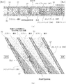
- FIG. 4 is a diagram schematically illustrating the behavior of the resin in the kneading / melting mechanism in the screw groove of the injection molding screw shown in FIG. 2 as one embodiment.
- FIG. 4 (a) shows one continuous virtual screw groove as one embodiment of the present invention, and shows a continuous transition of the kneading / melting state in the screw groove.
- FIG. 4 shows one continuous virtual screw groove as one embodiment of the present invention, and shows a continuous transition of the kneading / melting state in the screw groove.
- FIG. 4 (b) is a development of three adjacent flights, and a tributary flow is formed by providing a tributary formation opening (notch) in the flight section of the screw groove and the preceding screw groove adjacent thereto.
- FIG. 5 is a diagram corresponding to FIG. 4, and is a diagram schematically illustrating the behavior of the resin in the melting mechanism in the screw groove of the screw used in the injection molding method according to another embodiment of the present invention.
- FIG. 5A shows, as another embodiment of the present invention, a single continuous virtual screw groove, and shows a continuous transition of the kneading / melting state in the screw groove.
- FIG. 5 (b) is an expanded view of three adjacent flights, and a tributary flow is formed by providing a tributary formation opening (notch) in the flight section of the screw groove and the preceding screw groove adjacent to the screw groove.
- notch a tributary formation opening
- FIG.6 and FIG.7 is a screw which consists of one aspect for solving the same subject as this invention
- FIG. 8 is a conceptual diagram which illustrates the melting mechanism typically.
- FIG. 9 is a diagram schematically illustrating the behavior of the molten resin in the conventionally considered resin melting mechanism.
- An injection molding machine 1 according to an embodiment of the present invention shown in FIG. 1 is for molding a molded body using a thermoplastic granular resin material (resin pellet) as a raw material.
- the injection molding machine 1 has a mold clamping unit 10 and an injection unit 20 disposed on a machine base 2.
- the mold clamping unit 10 moves the movable die plate 12 forward and backward with respect to the fixed die plate 14 by bending the toggle link mechanism 11 using a driving force of a motor (not shown) as a driving source. Thereby, the movable mold 13 attached to the movable die plate 12 is subjected to the mold closing operation and the mold opening operation with respect to the fixed mold 15 attached to the fixed die plate 14.
- the injection unit 20 includes a cylindrical heating cylinder 21, an injection nozzle 22 provided at the tip of the heating cylinder 21, and a resin material that is accommodated in the heating cylinder 21 and supplied to the heating cylinder 21.
- An injection molding screw (hereinafter sometimes simply referred to as “screw 30”) that is kneaded and melted and pumped toward the nozzle side, a support member 23 that supports the screw 30 so as to be able to rotate and move forward and backward, and a heating cylinder 21 It has a hopper 24 for introducing a resin material therein, a hopper block 25 provided with the hopper 24, and a plurality of heaters 26 disposed outside the heating cylinder 21.
- the resin material is heated by the shearing force acting on the resin material when the screw 30 accommodated in the heating cylinder 21 is rotated, and the heating cylinder 21 is heated.
- the heater 26 is heated to a high temperature.
- the resin material supplied from the supply port 24a of the hopper 24 is kneaded and melted while being fed from the proximal end side (hopper side) to the distal end side (nozzle side) of the heating cylinder 21, and from the rear to the front.
- a molten resin flow is formed as a main flow toward the vehicle. In the molten resin flow as the main flow, solid resin pellets are kneaded and melted during the pressure feeding from the rear to the front.
- the kneaded and melted resin material is weighed by rotating the screw 30 back at a predetermined rotation speed by a rotational driving means such as a metering motor (not shown).
- a rotational driving means such as a metering motor (not shown).
- the screw 30 is advanced by an advancing / retracting drive means including an injection motor and a ball screw mechanism (not shown), whereby a predetermined amount of molten resin material is mold-closed through the injection nozzle 22.
- the product is molded by being injected into the inside.
- the injection nozzle 22 side is referred to as “front”, and the hopper side is referred to as “rear”.
- the screw 30 accommodated in the heating cylinder 21 will be described in detail. Since the configuration of the screw is the same as that of the present invention, first, the configuration of the screw shown in FIGS. 6 and 7 will be described as one embodiment in consideration of promotion of kneading / melting.
- the screw 30 is sequentially provided with a supply unit (A), a compression unit (B), and a measurement unit (C) from the base end side (rear side: hopper side) to the front end side (front side: nozzle side). Further, the screw 30 is provided so as to protrude from the outer peripheral surface of the rotary shaft portion 31 and the screw head 32 functioning as a backflow suppression valve provided at the tip of the rotary shaft portion 31.
- the spiral flight 33 is provided.
- the rotation shaft portion 31 is formed to have the same diameter throughout the supply portion (A), and the compression portion (B) has a continuous diameter from the base end side (hopper side) to the tip end side (nozzle side).
- the measuring portion (C) is formed to have the same diameter throughout, and has a larger diameter than the portion serving as the supply portion (A).
- the flights 33 formed on the outer periphery of the rotary shaft portion 31 are formed so that the distance from the axis L of the rotary shaft portion 31 to the outer peripheral tip surface is constant and the entire pitch is a spiral.
- the diameter of the rotating shaft part 31 increases from the base end side (hopper side) to the front end side (nozzle side), so that the compression part (B) has a base end side (hopper side).
- the depth of the screw groove M formed between the flights 33 decreases from the side) toward the tip side (nozzle side).
- the flight pitch (the length of the screw groove M in the axis L direction) continuously decreases from the proximal end (hopper side) toward the distal end (nozzle side). You may form.
- the flight 33 has a flight part 34 of the supply part (A), a flight part 35 of the compression part (B), and a flight part 36 of the weighing part (C).
- the flight part 34 of the supply part (A) is formed so that the angle ⁇ formed between the axis L of the rotary shaft part 31 and the base end side face 34a is constant throughout.
- the flight portion 34 of the supply unit (A) is a section arranged in the supply unit (A) on the proximal end side with respect to the compression unit (B) in the flight 33.
- the flight part 35 of the compression part (B) is connected to the flight part 34 of the supply part (A), and is connected to the axis L and the base of the rotary shaft part 31 from the base end side (hopper side) toward the tip end side (nozzle side).
- the angle ⁇ formed with the end side (hopper side) surface 35a is formed to be continuously increased.
- the flight part 35 of the compression part (B) is a section arranged in the compression part (B) in the flight 33.
- the flight portion 36 of the measuring portion (C) is connected to the flight portion 35 of the compression portion (B), and an angle ⁇ (where ⁇ ⁇ ⁇ ) formed between the axis L of the rotary shaft portion 31 and the base end side (hopper side) surface 36a. ) Is constant throughout.
- the flight part 36 of the measuring unit (C) is a section arranged in the measuring unit (C) on the tip side (nozzle side) of the compression unit (B) in the flight 33.
- the angle ⁇ is 20 degrees
- the angle ⁇ continuously changes from 20 degrees to 80 degrees
- the angle ⁇ is 80 degrees.
- the angles ⁇ , ⁇ , and ⁇ are other than these. It may be a size.
- the flight 33 includes the axis L of the rotating shaft 31, the flight part 34 of the supply part (A), the flight part 35 of the compression part (B), and the front end side surface of the flight part 36 of the weighing part (C) (on the left side in FIG. 7).
- the angle formed with the (facing surface) is constant, for example, 90 degrees.
- the axis line L of the rotating shaft part 31 and the flight 33 (specifically, compression) Part of the flight part 35) has a small angle with the base end side surface 35a, and thus there are many portions where the distance between the base end side surface 35a and the inner surface 21a of the heating cylinder 21 is narrow, and therefore, with respect to the solid bed (SB) Has a relatively strong shear force. Therefore, melting of the solid bed (SB) in the screw groove M can be promoted.
- the axis L of the rotary shaft portion 31 and the flight 33 (specifically, the compression portion Since the angle formed by the base end side surface 35a of the flight part 35) is large, the distance between the base end side surface 35a and the inner surface 21a of the heating cylinder 21 is wide, so that the molten resin material refluxed as shown by the arrows. The working shear force is suppressed.
- the flight portion 35 in a partial section of the compression portion (B) is located on the tip side (nozzle side) portion from the base end side (hopper side) portion.
- the angle ⁇ formed between the axis L of the rotating shaft portion 31 and the base end side surface 35a is increased.
- the molten resin material (melt pool MP) stays near the base end (hopper side) in the screw groove M formed between the flights 33, and is not near the tip end (nozzle side).
- Molten resin material (solid bed SB) stays.
- the shearing force acting on the resin material (solid bed SB) staying near the tip is strengthened on the base end side (hopper side) of the flight portion 35 of the compression portion (B) and weak on the tip side (nozzle side). can do. Therefore, since a strong shearing force can be applied to unmelted resin material (solid bed SB) at an early stage to promote melting, the molten state of the resin material can be achieved at an early stage and effectively melted. Can do.
- the angle ⁇ of the flight part 36 of the weighing unit (C) is larger than the angle ⁇ of the flight part 34 of the supply unit (A). Accordingly, a strong shearing force is applied to the unmelted resin material (solid bed SB) in the supply section (A) to promote melting, and the molten resin material (melt pool MP) in the measuring section (C). The molten state can be effectively leveled.
- the depth of the screw groove M of the flight portion 35 of the compression portion (B) is formed so as to become shallower from the base end side (hopper side) toward the tip end side (nozzle side), and the angle ⁇ is set to the base end side. It is formed so as to increase from the (hopper side) toward the tip side (nozzle side). Since it did in this way, the shear force which acts on the resin material which stagnates near the front-end
- tip in the screw groove M can be made comparatively strong initially, and can be gradually weakened as it progresses from the base end side to the front end side. . Therefore, the molten state of the resin material can be made more effective.
- the angle range is relatively large, and the shearing force can be changed in a wide range.
- the angle ⁇ of the flight portion 35 of the compression unit (B) is continuously changed from 20 degrees to 80 degrees, but is not limited thereto.
- the flight portion 35 of the compression section (B) is formed so that the angle ⁇ is constant over the whole, for example, 50 degrees, and the relationship between the angle ⁇ , the angle ⁇ , and the angle ⁇ is You may make it change in steps as it progresses to a supply part (A), a compression part (B), and a measurement part (C) so that it may become (gamma)> (beta)> (alpha).
- the kneading / melting model in the injection molding machine has been described in, for example, the conventionally known Tadmor model, but in the field of the injection molding machine, it has been verified that it is the same as the actual operation. Yes.
- the portion of the solid body called the solid bed (SB) has a relatively low temperature and is difficult to melt compared to the temperature of the portion called the melt pool (MP) in the molten state. Therefore, at an early stage of the injection molding model, the solid-phase solid bed (SB) portion, which is relatively low in temperature and hardly melted, is forcibly replaced with the molten liquid-phase melt pool (MP) portion. By kneading, melting of the solid phase portion can be promoted.
- the screw configuration of the above aspect is effective as a means for accelerating the kneading / melting of the molten resin material as the mainstream, but the present invention is an early stage of the plasticizing process according to a further novel aspect.
- the solid phase solid bed (SB) of the solid phase in the screw groove by introducing a part of the melt pool (MP) of the liquid phase in the preceding screw groove, or the solid bed (SB) of the solid phase
- MP melt pool
- SB solid bed
- the temperature of the unmelted portion is relatively low with respect to the melted portion of the resin material (melt pool portion MP), and when the solid bed (SB) is generated, it is difficult to melt. is there. Therefore, the inventors introduce a part of the melt pool (MP) having a higher temperature than the generated solid bed (SB) into the unmelted solid bed (SB) and forcibly knead (FIG. 4). (See (b)) or forcibly kneading by introducing a part of the unmelted solid bed (SB) into the melt pool (MP) where the temperature is high (see FIG. 5 (b)). As a result, various trial and error experiments and verifications were conducted to efficiently knead and dissolve both the solid and liquid phases of the resin material in the solid-liquid phase kneading zone at an early stage of the plasticization process.
- FIG. 2 and FIG. 3 As a specific injection molding machine for that purpose, what type of screw is adopted is shown in FIG. 2 and FIG. 3 as the flight configuration of the part called the compression part and the measurement part in the conventional screw. It is comprised as follows. This is because a notch 37 is provided as a branch flow forming opening in a part of the multi-threaded thread, and a part of the melt pool (MP) in the screw groove M preceding the part of the solid bed (SB) in the screw groove M. In other words, a tributary flow is formed in the notch portion of the flight so that the molten phase of the liquid phase jumps into the unmelted portion of the solid phase.
- MP melt pool
- SB solid bed
- a screw generally called a subflight screw has been known as a screw for promoting melting. This is intended to speed up melting by providing a plurality of flights in a plurality of measuring sections, but the unmelted part and the melted part are separated by the flight.
- a part of the unmelted portion (solid bed SB) in the screw groove M is replaced with a portion of the melted portion (melt pool MP) in the preceding screw groove M. It is set as the structure which forms a tributary so that it can introduce into.
- a part of the melted part (melt pool MP) in the preceding screw groove M or a part of the unmelted part (solid bed SB) in the screw groove M was formed in the spiral flight 33. It is possible to forcibly knead in the solid-liquid phase kneading zone through the branch forming opening 37, and to send it forward without dividing the melted portion and the unmelted portion.
- the formation of the tributary can be achieved by forming a notch 37 as a tributary forming opening in the spiral flight 33, which promotes the kneading and melting of both the solid and liquid phases in the solid and liquid phase kneading zone. Is.
- the conventional screw is composed of a continuous single thread, but a plurality of flights may be provided in order to make a structure in which a portion not melted is ground.
- the solid phase resin material solid bed SB staying in the first part of the screw groove M is sent forward, but the ability to melt at a certain region is reduced. End up. This is because the ability to melt by the rotation of the screw cannot keep up with the ability to pump.
- the transport speed seems to be relatively slow, but the molten resin flow as the mainstream Since there are few undissolved parts of the solid phase, stable plasticization can be achieved from an early stage of the plasticization process. This has been confirmed by experiments, and according to such a configuration, the amount of the resin material is increased or decreased, but the plasticizing ability is not affected.
- An injection molding method and an injection molding machine having a screw configuration include a flight that forms a screw groove M in addition to a molten resin flow as a main flow from a proximal end (hopper side) to a distal end side (nozzle side). Constructing a tributary through the tributary formation opening 37 (notch) between the flight 33 and the flight 33 is novel. In addition, this also makes it possible for the resin material to go back and forth. In the conventional parallel flight configuration, the resin material is pumped along the same screw groove. However, in the present invention, in addition to the molten resin flow as the main flow, a tributary formation opening that forms a tributary in a part of the flight 33.
- a notch 37 is provided as a part. As a result, it is possible to form a tributary that allows the resin material to move back and forth between the first lead and the second lead of the screw groove M, and kneading both solid-liquid phases. It will be promoted.
- the formation of the notch in the flight itself was a shape that has been conventionally known as a shape in which a melted resin material is agitated in a dalmage screw.
- the conventional dull image portion is formed on the relatively distal end side of the screw.
- a solid bed (SB) can be formed in a form in which a resin material melts, and is melted and liquefied in a molten resin flow as a main stream. That is, in the conventional kneading / melting model, there is no idea that the dull image is applied at the position of the screw where the resin material is not melted.
- a tributary formation opening 37 is formed in the spiral flight 33, and the solid-phase solid bed (SB) is formed from a relatively early stage in the plasticizing process.
- the solid and liquid phases are forcibly kneaded to melt the solid bed (SB).
- the present invention forces both solid and liquid phases by forcing a portion of a solid phase solid bed (SB) into a liquid phase melt pool (MP) in a preceding screw groove M. To promote melting of the solid bed (SB).
- a branch forming opening 37 is formed so as to form a tributary of the resin flow in the flight 33 between one screw groove M and the preceding screw groove M. (Notch portion) and a solid phase solid bed (SB) portion in one screw groove M, a part of the liquid phase melt pool (MP) in the preceding screw groove M It is forcibly introduced to knead the undissolved solid phase portion and the melted liquid phase portion from an early stage of the plasticizing process to promote melting.
- SB solid phase solid bed
- a notch portion 37 as a branch flow forming portion is provided in a flight portion called a compression portion arranged in a central portion of a conventional screw, and a melt pool (SB) is formed in a solid bed (SB) portion in the screw groove M.
- MP is introduced to promote melting of a solid phase in which both solid-liquid phases are forcibly kneaded.
- the solid bed (SB) and the melt pool (MP) are forcibly kneaded so as to enter and mix at an early stage of the plasticizing process.
- the present invention promotes melting of a solid phase in which a part of a solid bed (SB) is introduced into a melt pool (MP) in a preceding screw groove M to forcibly knead both solid and liquid phases.
- the position where the notch 37 is formed can be selected as appropriate, and is not limited by whether or not it is the compression part of the screw.
- the concept relating to the kneading / melting behavior is completely different between the injection molding method using the conventional injection molding model and the injection molding method using the injection molding model of the present invention.
- the present invention is a part of the solid bed (SB) of the solid phase of the single screw groove M or a part of the melt pool (MP) of the liquid phase of the preceding screw groove M.
- a good result can be obtained by being introduced into the kneading zone freely through the tributary opening 37 (notch) and forcibly kneading so that both the solid phase and the liquid phase dance.
- a part of the melt pool (MP) in the preceding screw groove is introduced into the kneading zone of the solid bed (SB) portion in the screw groove to force the solid phase solid bed (SB). It stirs and promotes melting of the solid phase part and does not stay as a large solid bed (SB).
- a part of the solid bed (SB) in one adjacent screw groove is introduced into the kneading zone of the melt pool (MP) part in the preceding screw groove to force both solid-liquid phases. Kneading to promote melting of the solid phase part.
- the solid bed (SB) part melts gradually along the molten resin flow as the main stream.
- the melted resin material (melt pool MP) and the unmelted resin material (solid bed SB) are forcibly mixed in the same flight to knead and solidify It consists of the idea of promoting the melting of
- the concept of the conventional subflight is an idea of applying excessive pressure to crush and melt by force by narrowing the flight interval sequentially.
- the screw 30 used in the injection molding method and injection molding machine of the present invention comprises a rear hopper side supply unit 30-1 and a front nozzle side kneading unit 30-2.
- the screw 30 has a supply portion 30-1 at the rear half of the total length of the screw and a kneading portion 30-2 at a front half.
- the transition part from the supply part 30-1 to the kneading part 30-2 is preferably the central part of the entire length of the screw.
- the central portion does not mean the position of exactly 1/2 of the total length of the screw, but the position of the intermediate portion of the total length of the screw.
- Reference numeral 32 in FIG. 2B denotes a screw head
- reference numeral 21 in FIG. 2C denotes a heating cylinder
- reference numeral 32 denotes a screw head.
- the resin material supplied from the hopper into the heating cylinder 21 is melted by the rotation of the screw 30 while being heated by the plurality of heaters 26 and is transferred to the front side on the nozzle side.
- the details of the kneading part 30-2 of the screw 30 of the present invention are shown in FIG. 3, and the kneading groove depth changing part 30-3 in which the dalmage is formed and the kneading groove depth in which the dalmage is formed are constant. It consists of part 30-4.
- the axial lengths of the kneading groove depth changing portion 30-3 and the kneading groove depth constant portion 30-4 are substantially equal. Although it is formed, it can be appropriately changed depending on the material used for molding.
- the screw shaft diameter D of the screw 30 is D1 at the rear of the kneading groove depth changing portion 30-3 on the hopper side, and at the transition portion between the kneading groove depth changing portion 30-3 and the kneading groove depth constant portion 30-4.
- the flight 33 is entirely formed from the central portion of the screw 30 toward the front side of the nozzle, and the flight 33 has a notch 37 as a branch forming portion. Is formed and constitutes a dalmage.
- the injection molding screw 30 of the present invention includes a rotary shaft portion 31 and a spiral flight 33 provided so as to project from the outer peripheral surface of the rotary shaft portion 31.
- a tributary formation opening (notch) 37 serving as a tributary formation portion is formed in a partial section of the flight 33 from the central portion of 30 toward the tip of the screw 30.
- a plurality of flights 33 are provided at least in a partial section in the axial direction of the rotating shaft portion 31, and the branch flow forming opening 37 is formed of the plurality of flights 33.
- the tributary formation opening 37 communicates the screw groove M on the rear side (hopper side) and the screw groove M on the front side (nozzle side) with the one flight 33 interposed therebetween. 37.
- the branch flow forming openings 37 are provided in two adjacent flights 33, and the branch flow forming openings 37 provided in the adjacent flights 33 are circumferentially connected to each other. They are offset.
- the solid bed (SB) in the screw groove M is sent in contact with the flight 33 because the resin material is pumped forward along the mainstream molten resin flow by the rotation of the screw.
- the notch 37 as the branch forming opening in the flight 33
- the melted portion (melt pool MP) in the screw groove M of another flight preceding the solid bed (SB) portion is mixed. It is done. Further, a part of the solid bed (SB) is mixed with the melted part (melt pool MP) in the screw groove M of another preceding flight.
- the melt film (MF) is sequentially grown along the main flow of the molten resin flow and scraped off to form a melt pool (MP), which is an unmelted part (solid
- MP melt pool
- the kneading / melting model of the present invention has a solid portion (solid) that is not melted from an early stage of the plasticizing process by a notch 37 as a tributary formation opening formed in a part of the flight 33.
- a part of the melted liquid phase part (melt film MF) in the screw groove M preceding the bed SB) is kneaded to rapidly melt the undissolved solid phase part (solid bed SB).
- the undissolved solid phase portion (solid bed SB) is introduced into the melted liquid phase portion (melt film MF) in the preceding screw groove M and kneaded.
- the solid phase portion (solid bed SB) that is not melted is rapidly melted. This approach is performed from a compression section located in the central part of the screw.
- the present invention relates to an injection molding method and injection capable of forming a forced solid-liquid phase kneading zone by coexisting both solid-liquid phases in the kneading zone of the screw groove M from an early stage of the plasticizing process. It relates to a molding machine. That is, this relates to an injection molding method and an injection molding machine based on a completely new injection molding model. Specifically, in the case of an injection molding machine using a 20 pitch screw over the entire length of the screw, a notched portion 37 is formed from a position about 1/2 (10 pitch) from the base end portion, and solid-liquid phase kneading is performed. It creates a state.
- the screw used in the injection molding method and the injection molding machine of the present invention has a main flight portion formed in the supply portion (30-1) of the base end portion, and a position close to about a half of the central portion of the total length of the screw.
- a multi-strip flight is formed, and a notch 37 as a branch forming opening is formed in the multi-strip flight.
- the formation position of the solid-liquid phase kneading zone is preferably approximately in the vicinity of half the central portion of the entire screw, but the optimum position varies depending on the type of resin material.
- the position is preferably formed from the position where the resin starts melting by the rotation of the screw.
- the present invention relates to an injection molding method based on a novel resin kneading / melting model, an injection molding machine, and a screw used in the injection molding method. It is also possible to form.
- the formation of the notch portion 37 as the flight tributary formation opening may be formed in the flight of only the solid-liquid phase kneading zone. You can have no flight.
- the notch 37 as a branch forming opening of the flight is forcibly forming a solid-liquid phase kneading zone, and the starting position for forming the notch 37 is the base end of the full length of the screw. A position in the vicinity of 1 ⁇ 2 from the portion is desirable.
- one of the specific embodiments of the present invention is notched in a multi-threaded flight formed from a position 1/2 to 3/4 from the base end of the entire length of the screw.
- the part 37 is formed.
- a notch portion 37 as a branch flow forming portion is formed in a multi-thread flight formed from a position 1/2 to a position 3/4 from the base end of the entire length of the screw.
- the notch part may be provided in the flight of the compression part of the screw shown in FIGS. 5 and 6.
Landscapes
- Engineering & Computer Science (AREA)
- Manufacturing & Machinery (AREA)
- Mechanical Engineering (AREA)
- Injection Moulding Of Plastics Or The Like (AREA)
Abstract
[Problem] To forcibly knead both solid and liquid phases at the early stage of a plasticization process and promote melting of a solid bed (SB) in a screw groove.
[Solution] Some of a solid phase part serving as a solid bed (SB) in a screw groove or some of a melt pool (MP) in a preceding screw groove is forcibly introduced into a solid-liquid phase kneading zone via a branch stream formation opening part forming a branch stream. As a result, resin materials of both solid and liquid phases are kneaded at an early stage to promote melting of the solid phase, and the kneaded and melted resin materials are measured. After the measurement operation, a screw is advanced by an advancing/retracting driving means provided with an injection motor and a ball screw mechanism to inject a measured amount of the melted resin materials into the cavity of closed molds via an injection nozzle.
Description
本願発明は、新規な混練・溶融モデルによる射出成形方法と、その方法を使用する新規な構成の射出成形機、及びそれらに用いられる新規な構成の射出成形用スクリューに関する。
The present invention relates to an injection molding method based on a novel kneading / melting model, an injection molding machine having a novel configuration using the method, and an injection molding screw having a novel configuration used therefor.
特に、本願発明は、可塑化プロセスの早い段階で、供給された樹脂材料の一部分を螺旋状スクリュー溝内の固相部或いは液相部の混練帯域に導入して固液両相の強制的な混練・溶融状態を経ることにより、供給樹脂材料の固液両相を強制的に混練して、固相部の溶融を促進する射出成形方法に関する。更には、その方法に使用される射出成形機、及びそれらに用いられる新規な構成の射出成形用スクリューに関する。本願発明において、供給された樹脂材料の一部分とは、スクリュー溝内の溶融状態にある液相部(メルトプール MP:Melt Pool)の一部分、或いは、未溶融状態にある固相部(ソリッドベッド SB:Solid Bed)の一部分である。
In particular, the invention of the present application introduces a part of the supplied resin material into the solid phase part or the kneading zone of the liquid phase part in the spiral screw groove at an early stage of the plasticizing process, thereby forcing the solid-liquid both phases. The present invention relates to an injection molding method for forcibly kneading a solid-liquid phase of a supplied resin material through a kneaded / molten state to promote melting of a solid phase part. Furthermore, the present invention relates to an injection molding machine used in the method, and an injection molding screw having a novel configuration used for them. In the present invention, a part of the supplied resin material is a part of a liquid phase part (melt pool MP: Melt Pool) in a molten state in a screw groove, or a solid phase part (solid bed SB) in an unmelted state. : Solid Bed).
本願発明は、具体的には、供給された樹脂ペレットをスクリューの回転により混練して溶融する際に、可塑化プロセスの早い段階での新規な固液両相の混練・溶融モデルによる射出成形方法に関する。ここで、新規な固液両相の混練・溶融モデルとは、スクリューの回転による主流としての溶融樹脂流れに対して、供給された樹脂材料の一部分を支流として形成するものである。つまり、螺旋状のスクリュー溝内の未溶融状態にある固相部(SB)の固相混練帯域内に、液相部(MP)の一部分を導入するか、或いは、より先行する螺旋状スクリュー溝内の溶融状態にある液相部(MP)の液相混練帯域内に、固相部(SB)の一部分を導入するかして、固相及び液相の両相を強制的に混練する固液相混練帯域を構成するものである。これにより、可塑化プロセスの早期の段階で、スクリュー溝内の未溶融状態にある固相部分(SB)を溶融状態にある液相部分(MP)と強制的に混練して固相部の溶融を促進する射出成形方法の提供が可能となる。また、その新規な方法に使用される射出成形機、及びそれらに用いられる新規な構成の射出成形用スクリューを提供する。
The present invention specifically relates to an injection molding method based on a novel solid-liquid both phase kneading / melting model at an early stage of the plasticization process when the supplied resin pellets are kneaded and melted by rotating a screw. About. Here, the new solid-liquid both-phase kneading / melting model is a method in which a part of the supplied resin material is formed as a branch flow with respect to the molten resin flow as the main flow by the rotation of the screw. In other words, a part of the liquid phase part (MP) is introduced into the solid phase kneading zone of the solid phase part (SB) in an unmelted state in the spiral screw groove, or a more advanced spiral screw groove In the liquid phase kneading zone of the liquid phase portion (MP) that is in the molten state, a solid phase portion (SB) is partially introduced or a solid phase that forcibly kneads both the solid phase and the liquid phase. This constitutes a liquid phase kneading zone. As a result, in the early stage of the plasticization process, the solid phase part (SB) in the melted state in the screw groove is forcibly kneaded with the liquid phase part (MP) in the molten state to melt the solid phase part. It is possible to provide an injection molding method that promotes the above. The present invention also provides an injection molding machine used for the novel method and an injection molding screw having a novel configuration used for them.
本願発明は、更に一つの実施態様として具体的には、スクリューの回転により供給された樹脂ペレットを混練・溶融して螺旋状スクリュー溝内の主流としての溶融樹脂流れを形成する際に、可塑化プロセスの早い段階で、螺旋状スクリュー溝間のフライト部の一部に、主流としての樹脂流れに対して支流を形成するように支流形成開口部(切欠き部)を設けるものである。それにより、スクリュー溝内の未溶融状態にある固相部のソリッドベッド(SB)に対して、それに先行するスクリュー溝内の溶融状態にある液相部のメルトプール(MP)の一部分を導入して、固液両相を強制的に混練するように構成したものである。このように、固液相混練帯域を経ることにより、未溶融状態の樹脂材料を可塑化プロセスの早期の段階で、強制的に液相部の一部分と混練して固相部の溶融を促進する射出成形方法と、その方法に使用される射出成形機、及びそれらに用いられる射出成形用スクリューを提供することができる。
In another embodiment, the present invention is specifically plasticized when the resin pellets supplied by the rotation of the screw are kneaded and melted to form a molten resin flow as the main flow in the spiral screw groove. In an early stage of the process, a tributary formation opening (notch) is provided in a part of the flight portion between the spiral screw grooves so as to form a tributary with respect to the resin flow as the main flow. As a result, a part of the melt pool (MP) in the liquid phase portion in the molten state in the screw groove preceding the solid bed (SB) in the solid phase portion in the unmelted state in the screw groove is introduced. Thus, both solid-liquid phases are forcibly kneaded. In this way, by going through the solid-liquid phase kneading zone, the resin material in an unmelted state is forcibly kneaded with a part of the liquid phase portion at an early stage of the plasticizing process to promote melting of the solid phase portion. It is possible to provide an injection molding method, an injection molding machine used in the method, and an injection molding screw used for them.
また、本願発明は、射出成形する樹脂の相違や射出条件の相違によっては、上記とは反対に、他の実施態様として、射出成形時に供給された樹脂ペレットをスクリューにより混練・溶融して螺旋状スクリュー溝内の主流としての溶融樹脂流れを形成する際に、上述した支流形成開口部(切欠き部)を通して、スクリュー溝内の未溶融状態のソリッドベッド(SB)の一部分を、先行するスクリュー溝内の溶融状態のメルトプール(MP)内に導入して、固液両相として強制的に混練するように固液相混練帯域を構成することができる。このような固液相混練帯域を経ることにより、溶融状態の樹脂材料を可塑化プロセスの早期の段階で急速に強制的に未溶融の固相部と混練し、固相部の溶融を促進する射出成形方法と、その方法に使用される射出成形機、及びそれらに用いられる射出成形用スクリューを提供することができる。
In addition, the present invention is different from the above, depending on the difference in the resin to be injection-molded and the difference in the injection conditions, as another embodiment, the resin pellet supplied at the time of injection molding is kneaded and melted with a screw to form a spiral shape. When forming a molten resin flow as a main flow in the screw groove, a part of the unmelted solid bed (SB) in the screw groove passes through the above-described branch flow forming opening (notch), and the preceding screw groove The solid-liquid phase kneading zone can be configured to be introduced into the melted melt pool (MP) and forcibly kneaded as both solid-liquid phases. By passing through such a solid-liquid phase kneading zone, the molten resin material is rapidly and forcibly kneaded with the unmelted solid phase portion at an early stage of the plasticizing process, and the melting of the solid phase portion is promoted. It is possible to provide an injection molding method, an injection molding machine used in the method, and an injection molding screw used for them.
何れも本願発明は、主流としての溶融樹脂流れに対して支流を形成して、可塑化プロセスの早い段階で、溶融状態の液相部分(メルトプール MP)の一部分、或いは、未溶融状態の固相部分(ソリッドベッド SB)の一部分を、夫々の相状態が相違するスクリュー溝内の混練帯域内に導入する新規な混練・溶融モデルによる射出成形方法と、その方法に使用される射出成形機に係り、更には、その射出成形方法及び射出成形機に用いられる射出成形用スクリューに関する。
In any case, the present invention forms a tributary to the molten resin flow as the main flow, and at an early stage of the plasticizing process, a part of the liquid phase part in the molten state (melt pool MP) or the solid state in the unmolten state. An injection molding method based on a new kneading / melting model in which a part of a phase portion (solid bed SB) is introduced into a kneading zone in a screw groove in which the respective phase states are different, and an injection molding machine used for the method Further, the present invention relates to an injection molding method and an injection molding screw used in an injection molding machine.
以上のとおり、本願発明は、供給された樹脂材料を混練して溶融する際に、可塑化プロセスの初期段階のスクリューによる供給樹脂の圧縮が始まるタイミングにおいて、螺旋状のスクリュー溝内の未溶融状態の固相部(ソリッドベッド SB)の一部分、或いは、それに先行するスクリュー溝内の溶融状態の液相部(メルトプール MP)の一部分の何れか一方を、上述の支流を形成する支流形成開口部(切欠き部)を通して固液相混練帯域内に導入して、固状態のソリッドベッド(SB)の一部分、或いは、液状態のメルトプール(MP)の一部分を強制的に混練し、固相部の溶融を促進して射出成形するものである。
As described above, in the present invention, when the supplied resin material is kneaded and melted, the unmelted state in the spiral screw groove at the timing when the supply resin is compressed by the screw at the initial stage of the plasticizing process. A tributary formation opening for forming the above-mentioned tributary of either a part of the solid phase part (solid bed SB) or a part of the liquid phase part (melt pool MP) in the molten state in the screw groove preceding it. It is introduced into the solid-liquid phase kneading zone through the (notch portion), forcibly kneading a part of the solid bed (SB) in the solid state or a part of the melt pool (MP) in the liquid state, The injection molding is promoted by promoting the melting of the resin.
本願発明は、より具体的には、スクリュー外周に形成された螺旋状のスクリュー溝内でソリッドベッド(SB)として滞留する固相部内に、それに先行するスクリュー溝内でメルトプール(MP)として流動する液相の一部分を、上述の支流形成開口部を通して強制的に導入させることにより、固液相混練帯域を形成するものである。それによって、可塑化プロセスの早期の段階で、樹脂材料の固液両相を急速に混練し、固相部の溶融を促進する射出成形方法に関するものである。本願発明の新規な可塑化プロセスは、樹脂材料を可塑化プロセスの早期の段階で、固相部 (ソリッドベッド SB)内に液相部(メルトプール MP)の一部分を強制的に急速に混練し、固相部の溶融を促進するために、フライトに支流形成開口部としての切欠き部を形成することにより達成できる。
More specifically, the present invention flows as a melt pool (MP) in a solid phase part that stays as a solid bed (SB) in a spiral screw groove formed on the outer periphery of the screw, and in a screw groove preceding it. A solid-liquid phase kneading zone is formed by forcibly introducing a part of the liquid phase to be introduced through the above-described branch flow forming opening. Accordingly, the present invention relates to an injection molding method in which both solid and liquid phases of a resin material are rapidly kneaded at an early stage of a plasticizing process to promote melting of a solid phase portion. In the novel plasticization process of the present invention, the resin material is forcibly and rapidly kneaded a part of the liquid phase part (melt pool MP) into the solid phase part (solid bed SB) at an early stage of the plasticization process. In order to promote melting of the solid phase portion, this can be achieved by forming a notch as a branch forming opening in the flight.
また、本願発明は、射出成形する樹脂の相違や射出条件の相違によっては、上記の可塑化プロセスとは反対に、スクリュー外周に形成されたスクリュー溝内でソリッドベッド(SB)として滞留する固相部の一部分を、それに先行するスクリュー溝内で液相部分として流動するメルトプール(MP)内に強制的に導入させることにより、固液相混練帯域を形成するものでもある。それによって、可塑化プロセスの早期の段階で、固液両相の樹脂材料を強制的に混練し、固相の溶融を促進する射出成形方法に関するものである。このような本願発明の可塑化プロセスは、樹脂材料を可塑化プロセスの早期の段階で、液相部内(メルトプール MP)に固相部分(ソリッドベッド SB)を強制的に混練して固相の溶融を促進するために、フライトに支流形成部としての支流形成開口部(切欠き部)を形成することにより達成できる。
Further, according to the present invention, the solid phase staying as a solid bed (SB) in the screw groove formed on the outer periphery of the screw, contrary to the plasticizing process, depending on the difference in the resin to be injection-molded and the difference in the injection conditions. A solid-liquid phase kneading zone is also formed by forcibly introducing a part of the part into a melt pool (MP) that flows as a liquid phase part in a screw groove preceding the part. Accordingly, the present invention relates to an injection molding method for forcibly kneading a solid-liquid resin material at an early stage of the plasticizing process and promoting melting of the solid phase. In such a plasticization process of the present invention, in the early stage of the plasticization process, the solid phase part (solid bed SB) is forcibly kneaded in the liquid phase part (melt pool MP) and the solid phase part is formed. In order to promote melting, this can be achieved by forming a tributary formation opening (notch) as a tributary formation portion in the flight.
さらに、本願発明は、以上の方法に使用される射出成形機に係り、更には、その射出成形機に用いられる射出成形用スクリューに関する。
Further, the present invention relates to an injection molding machine used in the above method, and further relates to an injection molding screw used in the injection molding machine.
本願明細書において、用語の意義は以下のとおりとする。
「混練・溶融モデル」とは、可塑化プロセスにおいて、スクリューの回転により供給された樹脂材料が、射出成形機内で加熱され、混練され、溶融される際の樹脂材料の主流としての樹脂流れの挙動の変化の形態をいう。
「固液相混練帯域:Solid Liquid Mixing Zone」とは、射出成形機における樹脂材料の混練・溶融モデルにおいて、スクリュー溝とそれに隣接して先行するスクリュー溝の間の螺旋状フライトに支流を形成するための支流形成開口部(切欠き部)を設け、ソリッドベッド(SB)或いは、メルトプール(MP)の何れかの相の一部分を他の相内に導入して固液両相を強制的に混練して、ソリッドベッド(SB)の溶融を促進させるスクリュー溝内での混練帯域をいう。スクリュー溝内に構成される「混練帯域」は、混練する樹脂の相状態により以下のように称する。
「固相混練帯域:Solid bed Mixing Zone」とは、射出成形機における樹脂材料の混練・溶融モデルにおいて、固相部のソリッドベッド(SB)がスクリュー溝内で混練される混練帯域をいう。
「液相混練帯域:Melt Pool Mixing Zone」とは、射出成形機における樹脂材料の混練・溶融モデルにおいて、液相部のメルトプール(MP)がスクリュー溝内で混練される混練帯域をいう。 In the present specification, the meanings of terms are as follows.
The “kneading / melting model” is the behavior of the resin flow as the main flow of the resin material when the resin material supplied by the rotation of the screw is heated, kneaded and melted in the plasticizing process in the plasticizing process. The form of change.
“Solid Liquid Mixing Zone” is a model of resin material kneading and melting in an injection molding machine that forms a tributary in a spiral flight between a screw groove and the adjacent screw groove. Forcibly forming both solid and liquid phases by introducing a part of the phase of either the solid bed (SB) or melt pool (MP) into the other phase. A kneading zone in the screw groove that kneads and promotes melting of the solid bed (SB). The “kneading zone” configured in the screw groove is referred to as follows depending on the phase state of the resin to be kneaded.
“Solid bed mixing zone” refers to a kneading zone in which a solid bed (SB) of a solid phase portion is kneaded in a screw groove in a resin material kneading / melting model in an injection molding machine.
The “liquid phase kneading zone: Melt Pool Mixing Zone” refers to a kneading zone in which the melt pool (MP) of the liquid phase portion is kneaded in the screw groove in a resin material kneading / melting model in an injection molding machine.
本願発明において、より具体的に、固液相混練帯域においては、スクリュー溝内の未溶融の固形粒の塊により形成されるソリッドベッド(SB)の混練帯域(固相混練帯域)内に、それに先行するスクリュー溝内からの支流を形成して、メルトプール(MP)の一部分を強制的に導入し、固相状態(ソリッドベッドSB)の部分と液相状態の部分(メルトプールMP)とを強制的に混練して固相部の溶融を促進させる。
また、他の実施態様として、本願発明は、射出成形する樹脂の相違や射出条件の相違によっては上述の形態とは反対に、スクリュー溝内の未溶融の固形粒の塊により形成されるソリッドベッド(SB)の一部分を、それに先行するスクリュー溝内の固相混練帯域へ向けた支流を通してメルトプール(MP)内に強制的に導入し、固相状態(ソリッドベッドSB)の部分と液相状態の(メルトプールMP)部分とを強制的に混練して固相状態(ソリッドベッドSB)の溶融を促進させるものでもある。 In the present invention, more specifically, in the solid-liquid phase kneading zone, in the kneading zone (solid phase kneading zone) of the solid bed (SB) formed by the lump of unmelted solid particles in the screw groove, A tributary from the preceding screw groove is formed, a part of the melt pool (MP) is forcibly introduced, and a part in the solid phase (solid bed SB) and a part in the liquid phase (melt pool MP) Forced kneading to promote melting of the solid phase part.
As another embodiment, the present invention is a solid bed formed by a lump of unmelted solid particles in the screw groove, contrary to the above-described form, depending on the difference in resin to be injection molded and the difference in injection conditions. A part of (SB) is forcibly introduced into the melt pool (MP) through a tributary toward the solid-phase kneading zone in the screw groove that precedes it, and the solid-phase part (solid bed SB) and the liquid-phase state The (melt pool MP) portion of the material is forcibly kneaded to promote melting in the solid phase (solid bed SB).
「スクリュー溝」と「それに先行するスクリュー溝」とは、射出成形用スクリューの周りに形成される繋がった一本の溝部であるが、螺旋状に隣り合う溝部を指していう場合に用いる。
「主流としての樹脂流れ」と「支流」とは、「射出成形用スクリューの螺旋溝内を樹脂供給ホッパ側からノズル側に向かって流れる溶融樹脂流れ」の「主流」と、「スクリュー溝」と「それに先行するスクリュー溝」との間のフライト部に形成された支流形成開口部(切欠き部)を通した「支流」としての流れをいう。 “Screw groove” and “screw groove preceding it” are a single continuous groove formed around the injection molding screw, but are used when referring to spiral adjacent grooves.
“Resin flow as main flow” and “branch flow” means “main flow” of “melt resin flow flowing from the resin supply hopper side toward the nozzle side in the spiral groove of the screw for injection molding” and “screw groove” It refers to a flow as a “branch” through a tributary formation opening (notch) formed in the flight part between the “screw groove preceding it”.
特許文献1には、射出成形機に用いられる従来のスクリューが開示されている。このスクリューは、回転軸部と、該回転軸部の外周から突出する螺旋状のフライトとを有しており、回転軸部の回転により、基端側(ホッパ側)から先端側(ノズル側)に向けて、軸線方向に沿って樹脂材料を送りながら材料を溶融するように構成されている。そのためには、樹脂材料の溶融状態を均一にすることが必要である。
Patent Document 1 discloses a conventional screw used in an injection molding machine. This screw has a rotating shaft portion and a spiral flight projecting from the outer periphery of the rotating shaft portion, and is rotated from the proximal end side (hopper side) to the distal end side (nozzle side) by the rotation of the rotating shaft portion. The material is melted while feeding the resin material along the axial direction. For that purpose, it is necessary to make the molten state of the resin material uniform.
この点に関して、従来技術では、スクリューのフライト間のスクリュー溝の深さを調整することにより、樹脂材料にはたらくせん断力を変えて、樹脂材料の溶融状態をならしていた。
In this regard, in the prior art, by adjusting the depth of the screw groove between the flights of the screw, the shearing force acting on the resin material is changed to smooth the molten state of the resin material.
射出成形において、成形品の品質を安定させるためには、前述のとおり、主流としての溶融樹脂流れにおける固液両相の樹脂材料の溶融状態を均一にすることが必要である。そこで、本願発明者等は、樹脂材料を可塑化プロセスの比較的早い段階で全体的に混練・溶融して溶融状態を均一にすることが、射出成形において重要な要素の一つであるとの知見を得たものである。
In injection molding, in order to stabilize the quality of a molded product, as described above, it is necessary to make the molten state of the solid-liquid both phase resin material uniform in the molten resin flow as the main stream. Therefore, the inventors of the present application said that it is one of the important elements in injection molding that the resin material is kneaded and melted overall at a relatively early stage of the plasticizing process to make the molten state uniform. We have obtained knowledge.
一般的に射出成形機に用いられるスクリュー(全長L)は、樹脂投入口側(ホッパ側)から樹脂吐出口側(ノズル側)に向け、順に、供給部・圧縮部・計量部という構成となっている。このようなスクリューの形状及び構成とすることにより、供給された樹脂材料は、効率よく混練され、溶融されると考えられていた。そして、このシリンダ内で回転するスクリューにより樹脂ペレットが溶融していくモデルについては多くの研究がなされて明らかになっている。
Generally, a screw (full length L) used in an injection molding machine has a structure of a supply unit, a compression unit, and a metering unit in order from the resin inlet side (hopper side) to the resin discharge port side (nozzle side). ing. By adopting such a screw shape and configuration, the supplied resin material was thought to be efficiently kneaded and melted. Many studies have been made on the model in which resin pellets are melted by the screw rotating in the cylinder.
これらは、主に、スクリューを用いた押出機における樹脂材料の可塑化の過程のモデルとして検討されたものであるが、現在では、スクリューを用いた射出成形機における樹脂材料の可塑化モデルとしても知られて一般化されている。例えば、非特許文献1に説明されているTadmorモデルが知られている。これは本願発明においても共通する技術が多いので以下に詳細に説明する。
These were mainly studied as a model of the plasticization process of resin material in an extruder using a screw, but at present, as a model of plasticization of a resin material in an injection molding machine using a screw. Known and generalized. For example, the Tadmor model described in Non-Patent Document 1 is known. This is common in the present invention and will be described in detail below.
一般的な射出成形用スクリュー130は、図9(a)に示すように、回転軸部の外周部から突出する螺旋状のフライト133によりスクリュー溝Mが形成されている。つまり、フライト133は、スクリュー130の外周に、所定のフライトピッチ(FP:Flight Pitch)により、所定のフライト幅(FW:Flight Width)で、所定のフライト深さ(FD:Flight Depth)をもって螺旋状に形成されている。これにより、スクリュー130の外周に螺旋状のスクリュー溝Mが連続して形成される。このような射出成形用スクリュー130を用いた際のTadmorモデルに代表される射出成形用スクリューのスクリュー溝内における樹脂材料の混練・溶融メカニズムを図9(b)に模式的に示す。
As shown in FIG. 9A, a general injection molding screw 130 has screw grooves M formed by spiral flights 133 protruding from the outer peripheral portion of the rotating shaft portion. In other words, the flight 133 is spirally formed on the outer periphery of the screw 130 with a predetermined flight pitch (FP: Flight Pitch), a predetermined flight width (FW: Flight Width), and a predetermined flight depth (FD: Flight Depth). Is formed. As a result, a spiral screw groove M is continuously formed on the outer periphery of the screw 130. FIG. 9B schematically shows the kneading and melting mechanism of the resin material in the screw groove of the injection molding screw represented by the Tadmor model when such an injection molding screw 130 is used.
このような射出成形用スクリュー130において、ホッパから投入された固形の樹脂材料は、スクリュー130の回転により、フライト133間に形成されたスクリュー溝M内を射出ノズル側(図9の左側)に向けて、溶融樹脂流れの主流として圧送される。このスクリュー130の回転による樹脂材料の圧送の際に、樹脂材料には剪断力が作用し、加熱シリンダ121からも加熱されて、樹脂は順次溶融される。それにより、スクリュー溝M内の樹脂材料の固液相の状態は、ソリッドベッド(SB)と呼ばれる未溶融樹脂材料の固相部と、加熱シリンダ121の内周面121aに接したメルトフィルム(MF:Melt Film)と呼ばれる液状の溶融層部と、回転するフライト133により、メルトフィルム(MF)が掻き集められたメルトプール(MP)と呼ばれる液状の循環溶融相とが形成される。供給された樹脂ペレットは、スクリュー130の回転により、樹脂投入口側(ホッパ側)から樹脂吐出口側(ノズル側)に向けて圧送されるにつれてメルトプール(MP)の割合が多くなり溶融が進むものである。
In such an injection molding screw 130, the solid resin material introduced from the hopper is directed toward the injection nozzle side (left side in FIG. 9) in the screw groove M formed between the flights 133 by the rotation of the screw 130. Then, it is pumped as the main flow of the molten resin flow. When the resin material is pumped by the rotation of the screw 130, a shearing force acts on the resin material and is heated from the heating cylinder 121, and the resin is sequentially melted. Thereby, the state of the solid-liquid phase of the resin material in the screw groove M is a melt film (MF) in contact with the solid phase portion of the unmelted resin material called a solid bed (SB) and the inner peripheral surface 121a of the heating cylinder 121. : Melt 溶 融 Film) and a rotating flight 133 form a liquid circulating molten phase called a melt pool (MP) in which the melt film (MF) is scraped. As the supplied resin pellets are pumped from the resin charging port side (hopper side) toward the resin discharge port side (nozzle side) by the rotation of the screw 130, the ratio of the melt pool (MP) increases and melting progresses. It is a waste.
加熱シリンダ121の内周面121aに接したメルトフィルム(MF)が形成されると、スクリュー130の回転により、剪断エネルギーによる発熱が加わり、スクリュー溝M内のソリッドベッド(SB)が順次溶融されてメルトフィルム(MF)がスクリューの径方向に成長する。そして、メルトフィルム(MF)の厚さがフライト133の外周面と加熱シリンダ121の内周面121aで形成されるクリアランスC以上の厚みに成長すると、前進してくるフライト133によってメルトフィルム(MF)が掻き取られる。掻き取られた、メルトフィルム(MF)は、スクリュー溝Mの樹脂投入口側(ホッパ側)に集められて循環するメルトプール(MP)が成長していき、矢印で示すように還流しながら混練される。
When the melt film (MF) in contact with the inner peripheral surface 121a of the heating cylinder 121 is formed, heat generated by shearing energy is applied by the rotation of the screw 130, and the solid bed (SB) in the screw groove M is sequentially melted. A melt film (MF) grows in the radial direction of the screw. When the thickness of the melt film (MF) grows to a thickness equal to or greater than the clearance C formed by the outer peripheral surface of the flight 133 and the inner peripheral surface 121a of the heating cylinder 121, the melt film (MF) is moved forward by the flight 133. Is scraped off. The melt film (MF) scraped off is collected at the resin inlet side (hopper side) of the screw groove M, and a circulating melt pool (MP) grows, and is kneaded while refluxing as indicated by an arrow. Is done.
また、従来の射出成形機のスクリューである特許文献1(特開2016-182687号公報)は、スクリューの振れ回りを抑制し、スクリューとシリンダとの摩擦を低減した射出装置の提供することを課題としている。
この特許文献1には、成形材料を加熱するシリンダと、前記シリンダ内に回転自在に配設されるスクリューとを有する、射出装置が開示されている。前記スクリューは、回転軸部と、前記回転軸部の外周から突出する螺旋状のフライトとを有し、前記回転軸部の回転によって前記回転軸部に沿って上流側から下流側に成形材料を送るものである。前記フライトは、螺旋状の第1フライト部と、前記第1フライト部よりも下流側に配される螺旋状の第2フライト部とを有し、前記第2フライト部は、頂部の上流側端部の高さよりも頂部の下流側端部の高さが低い異径フライト部である。前記第2フライト部のピッチに対する前記第2フライト部のフライト幅の割合が、前記第1フライト部のピッチに対する前記第1フライト部のフライト幅の割合よりも大きい。 Further, Patent Document 1 (Japanese Patent Laid-Open No. 2016-182687), which is a screw of a conventional injection molding machine, provides an injection device that suppresses the swirling of the screw and reduces the friction between the screw and the cylinder. It is said.
Patent Document 1 discloses an injection device having a cylinder for heating a molding material and a screw rotatably disposed in the cylinder. The screw has a rotating shaft portion and a spiral flight protruding from the outer periphery of the rotating shaft portion, and the molding material is moved from the upstream side to the downstream side along the rotating shaft portion by the rotation of the rotating shaft portion. To send. The flight has a spiral first flight part and a spiral second flight part arranged on the downstream side of the first flight part, and the second flight part has an upstream end at the top. This is a different-diameter flight portion in which the height of the downstream end portion of the top portion is lower than the height of the portion. The ratio of the flight width of the second flight part to the pitch of the second flight part is larger than the ratio of the flight width of the first flight part to the pitch of the first flight part.
この特許文献1には、成形材料を加熱するシリンダと、前記シリンダ内に回転自在に配設されるスクリューとを有する、射出装置が開示されている。前記スクリューは、回転軸部と、前記回転軸部の外周から突出する螺旋状のフライトとを有し、前記回転軸部の回転によって前記回転軸部に沿って上流側から下流側に成形材料を送るものである。前記フライトは、螺旋状の第1フライト部と、前記第1フライト部よりも下流側に配される螺旋状の第2フライト部とを有し、前記第2フライト部は、頂部の上流側端部の高さよりも頂部の下流側端部の高さが低い異径フライト部である。前記第2フライト部のピッチに対する前記第2フライト部のフライト幅の割合が、前記第1フライト部のピッチに対する前記第1フライト部のフライト幅の割合よりも大きい。 Further, Patent Document 1 (Japanese Patent Laid-Open No. 2016-182687), which is a screw of a conventional injection molding machine, provides an injection device that suppresses the swirling of the screw and reduces the friction between the screw and the cylinder. It is said.
以上に説明したように、樹脂材料を射出成形する場合に、樹脂材料の溶融・混練を均一にするためにスクリューにフライトを設けることは、従来から一般的に行われている。しかしながら、樹脂材料は種類ごとに特性が異なることから、樹脂材料に合わせてスクリュー溝の仕様(ピッチ、幅、深さ等)を調整するためには高度の技術や経験が必要である。その際、不十分な調整によりスクリュー溝が浅すぎたりすると、樹脂材料に働くせん断力が強くなり過ぎてヤケが生じたり、逆に、スクリュー溝が深過ぎると樹脂材料に働くせん断力が弱くなり過ぎて溶け残りが生じたりしてしまう。そのため、樹脂材料の溶融状態を均一にすることが困難であった。
As described above, when a resin material is injection-molded, it has been conventionally performed to provide a screw with a flight in order to make the resin material melt and kneaded uniformly. However, since resin materials have different characteristics depending on the type, advanced technology and experience are required to adjust the screw groove specifications (pitch, width, depth, etc.) according to the resin material. At that time, if the screw groove is too shallow due to insufficient adjustment, the shearing force acting on the resin material becomes too strong, causing burns. Conversely, if the screw groove is too deep, the shearing force acting on the resin material becomes weak. It will pass too much and melt away. Therefore, it has been difficult to make the molten state of the resin material uniform.
特に、従来の一般的な形状のスクリューで見られる溶融形態では、着色材を添加したものなどといった材料を均一に混練しなければならないものに対しては、効率的な混練・溶融が達成できてはいなかった。
In particular, in the melted form found in conventional general-purpose screws, efficient kneading and melting can be achieved for materials that must be uniformly kneaded, such as those with added colorants. I didn't.
このような状況で、本願発明者等は、種々の樹脂材料の溶融メカニズムについて鋭意実験的な検討を行った結果、スクリュー溝とそれに隣接して先行するスクリュー溝との間のフライト部に支流形成開口部(切欠き部)を形成して、ソリッドベッド(SB)の一部分又はメルトプール(MP)の一部分を、固液相混練帯域内に導き入れて、可塑化プロセスの早期に、固相と液相とを強制的に混練し、固相の溶融を促進させる帯域を設けることが好ましいことを見いだしたものである。
In such a situation, the inventors of the present application conducted extensive experimental studies on the melting mechanism of various resin materials, and as a result, formed a tributary flow in the flight portion between the screw groove and the preceding screw groove. An opening (notch) is formed, and a part of the solid bed (SB) or a part of the melt pool (MP) is introduced into the solid-liquid phase kneading zone, and at an early stage of the plasticization process, the solid phase It has been found that it is preferable to provide a zone for forcibly kneading the liquid phase and promoting melting of the solid phase.
つまり、本願発明者らは、より具体的には、スクリュー溝とそれに隣接して先行するスクリュー溝との間の壁を構成するフライト部に支流形成開口部(切欠き部)を形成して、スクリュー溝内に滞留する未溶融のソリッドベッド(SB)領域へ、先行するスクリュー溝のメルトプール(MP)の一部分を導き入れることにより、ソリッドベッド(SB)を早期に溶融促進させる構成を見いだしたものである。また、それとは反対に、射出成形する樹脂の相違や射出条件の相違によっては、スクリュー溝内に滞留する未溶融のソリッドベッド(SB)領域の一部を、隣接して先行するスクリュー溝のメルトプール(MP)内に導き入れることにより、ソリッドベッド(SB)を早期に溶融促進させる構成が望ましいことを見いだしたものである。
That is, the inventors of the present application, more specifically, by forming a tributary formation opening (notch) in the flight portion constituting the wall between the screw groove and the preceding screw groove adjacent thereto, We have found a structure that accelerates melting of the solid bed (SB) early by introducing a part of the melt pool (MP) of the preceding screw groove into the unmelted solid bed (SB) region that stays in the screw groove. Is. On the other hand, depending on the difference in the resin to be injection-molded and the difference in the injection conditions, a part of the unmelted solid bed (SB) region staying in the screw groove may be adjacent to the melt of the preceding screw groove. It has been found that it is desirable to have a configuration in which the solid bed (SB) is accelerated to be melted at an early stage by introducing it into the pool (MP).
本願発明では、何れのプロセス(図4(a)(b)、及び図5(a)(b)参照)に拠っても、スクリュー溝内の固液相混練帯域内でのソリッドベッド(SB)とメルトプール(MP)との強制的な混練・溶融により、ソリッドベッド(SB)の溶融を促進するものであるが、供給樹脂材料の混練・溶融を促進するという同一の課題の観点から、その一態様としての射出成形用スクリューの構成を図6及び図7に示す。
In the present invention, the solid bed (SB) in the solid-liquid phase kneading zone in the screw groove, regardless of which process (see FIGS. 4 (a) (b) and 5 (a) (b)). And the melt pool (MP) are forcibly kneaded and melted to promote melting of the solid bed (SB). From the viewpoint of the same problem of promoting kneading and melting of the supplied resin material, The configuration of an injection molding screw as one embodiment is shown in FIGS.
この図6及び図7に示すスクリューの実施態様では、回転軸部とその外周面に突出して設けられた螺旋状フライトを有し、回転軸部の軸線とフライトの基端側面とのなす角度が、ホッパ側よりノズル側で漸次大きくなるように形成したものである。その際は、フライト間のスクリュー溝Mの深さ又はスクリュー溝の軸線方向の長さがホッパ側からノズル側に向かうにしたがって小さくなるように形成された圧縮部を有している。フライトを形成した区間内の圧縮部区間においては、ホッパ側からノズル側に向かうにしたがってフライトの角度が漸次連続的に大きくなるようにすることが好ましい。
In the embodiment of the screw shown in FIGS. 6 and 7, the rotary shaft portion and the spiral flight provided on the outer peripheral surface thereof are provided, and the angle formed between the axis of the rotary shaft portion and the base end side surface of the flight is These are formed so as to gradually become larger on the nozzle side than on the hopper side. In that case, it has the compression part formed so that the depth of the screw groove M between flights or the length of the axial direction of a screw groove may become small as it goes to a nozzle side from a hopper side. In the compression section in the section in which the flight is formed, it is preferable that the flight angle gradually and continuously increase from the hopper side toward the nozzle side.
このように、フライトを形成する場合には、圧縮部より先端側に配置された区間の角度が、圧縮部よりホッパ側に配置された区間の角度よりも大きくなるようにフライトが形成されていることが好ましい。
Thus, when forming a flight, the flight is formed such that the angle of the section disposed on the tip side from the compression section is larger than the angle of the section disposed on the hopper side from the compression section. It is preferable.
このような態様を採用することにより、フライトの少なくとも一部の区間が、当該区間における基端側(ホッパ側)の部分より先端側(ノズル側)の部分の方が回転軸部の軸線とフライトの基端側面とのなす角度が大きくなるように形成される。その際、フライト間に形成されるスクリュー溝M内ではホッパ寄りに溶融された樹脂材料が滞留しかつノズル寄りに未溶融の樹脂材料が滞留する。そして、このように構成したことにより、ノズル寄りに滞留する樹脂材料にはたらくせん断力を、フライトの一部の区間または全体において、ホッパ側の部分で強く、ノズル先端側の部分で弱くすることができる。
By adopting such a mode, at least a part of the flight is such that the tip side (nozzle side) portion of the flight and the axis of the rotating shaft portion are in flight with the base side (hopper side) portion. It is formed such that the angle formed with the base end side surface of the is large. At that time, in the screw groove M formed between the flights, the molten resin material stays near the hopper and the unmelted resin material stays near the nozzle. With this configuration, the shearing force acting on the resin material staying closer to the nozzle can be strong at the hopper side portion and weak at the nozzle tip side portion in a partial section or the whole of the flight. it can.
そのために、早い段階で未溶融の樹脂材料に対して強いせん断力を働かせて溶融を促進するとともに、溶融後の樹脂材料に過度のせん断力がはたらくことを抑制することができるので、樹脂材料の溶融状態を早期に効果的にならすことができる。
For this reason, a strong shearing force is applied to an unmelted resin material at an early stage to promote melting, and an excessive shearing force can be prevented from acting on the resin material after melting. The molten state can be effectively leveled at an early stage.
本願発明では、このような態様に加えて、可塑化プロセスの早期の段階での混練・溶融の達成までのプロセスを考慮した具体的な態様として、螺旋状のスクリュー溝とそれに隣接して先行するスクリュー溝の間のフライト部に支流形成開口部(切欠き部)を形成して、ソリッドベッド(SB)の一部分又はメルトプール(MP)の一部分を固液相混練帯域内に強制的に導き入れることにより、可塑化プロセスの早期に固液両相を強制的に混練し、固相の溶融を促進させる帯域を設けることが好ましいことを見いだしたものである(図4,5参照)。なお、図4及び図5では支流形成開口部の図示形態が相違しているが、これらはフライトの一部分に切欠き開口部が形成されていることを概念的に示しているものである。
In the present invention, in addition to such a mode, as a specific mode in consideration of the process up to the achievement of kneading / melting at an early stage of the plasticizing process, a spiral screw groove and a preceding one are adjacent thereto. A tributary formation opening (notch) is formed in the flight part between the screw grooves, and a part of the solid bed (SB) or a part of the melt pool (MP) is forcibly introduced into the solid-liquid phase kneading zone. Thus, it has been found that it is preferable to provide a zone for forcibly kneading both solid-liquid phases and promoting melting of the solid phase at an early stage of the plasticization process (see FIGS. 4 and 5). 4 and 5, the illustration forms of the branch flow forming opening are different, but these conceptually show that a notch opening is formed in a part of the flight.
より具体的には、本願発明は、図4(a),(b)に示すように、螺旋状のスクリュー溝Mとそれに隣接して先行するスクリュー溝Mの間のフライト33に支流形成開口部(切欠き部)37を形成して、スクリュー溝M内のソリッドベッド(SB)としての固相部分内に、先行するスクリュー溝M内のメルトプール(MP)の一部分を強制的に導き入れるものである。図4(b)には、未溶融部に溶融部の一部が支流形成開口部(切欠き部)37を通して飛び込む状態が示されている。これにより、樹脂材料を可塑化プロセスの早期の段階において、固液相が急速に混練され固相部の溶融が促進される新規な混練・溶融モデルから成る射出成形方法が達成できるものである。
More specifically, according to the present invention, as shown in FIGS. 4A and 4B, a branch forming opening is formed in the flight 33 between the spiral screw groove M and the preceding screw groove M adjacent thereto. (Notch) 37 is formed to forcibly introduce a part of the melt pool (MP) in the preceding screw groove M into the solid phase portion as the solid bed (SB) in the screw groove M It is. FIG. 4B shows a state in which a part of the melted part jumps into the unmelted part through the tributary formation opening (notch part) 37. This makes it possible to achieve an injection molding method comprising a novel kneading / melting model in which the solid-liquid phase is rapidly kneaded and the melting of the solid phase part is promoted at an early stage of the plasticizing process of the resin material.
また、このような射出成形モデルの樹脂の挙動とは反対に、射出成形する樹脂の相違や射出条件の相違によっては、図5(a),(b)に示すように、螺旋状のスクリュー溝Mとそれに隣接して先行するスクリュー溝Mの間のフライト33に支流形成開口部(切欠き部)37を形成して、ソリッドベッド(SB)としての固相部分の一部分を、先行するスクリュー溝M内のメルトプール(MP)内に強制的に導き入れるものである。図5(b)には、溶融部に未溶融部の一部が支流形成開口部(切欠き部)37を通して飛び込む状態が示されている。これにより、樹脂材料を可塑化プロセスの早期の段階において急速に固液両相が混練され、固相の溶融が促進される新規な混練・溶融モデルから成る射出成形方法が達成できるものである。
Further, contrary to the resin behavior of such an injection molding model, depending on the difference in the resin to be injection molded and the difference in the injection conditions, as shown in FIGS. 5 (a) and 5 (b), a spiral screw groove A tributary formation opening (notch) 37 is formed in a flight 33 between M and the preceding screw groove M adjacent thereto, so that a part of the solid phase portion as a solid bed (SB) is replaced with the preceding screw groove. It is forcibly introduced into the melt pool (MP) in M. FIG. 5B shows a state in which a part of the unmelted portion jumps into the melted portion through the tributary flow forming opening (notched portion) 37. As a result, an injection molding method comprising a novel kneading / melting model in which both solid-liquid phases are rapidly kneaded in an early stage of the plasticizing process of the resin material, and melting of the solid phase is promoted can be achieved.
さらに、本願発明は、本願発明の方法に使用される射出成形機及び射出成形用ノズルを提案するものである。
Furthermore, the present invention proposes an injection molding machine and an injection molding nozzle used in the method of the present invention.
本発明の射出成形方法は、
樹脂材料をホッパから加熱シリンダ内に供給し、該加熱シリンダ内で螺旋状フライトを有するスクリューを回転して、ホッパから供給された樹脂材料を前記螺旋状フライトにより形成されたスクリュー溝内で混練・溶融しながら前方に送る際に、
前記スクリュー溝とその溝に先行するスクリュー溝との間の螺旋状フライトに支流を形成する支流形成開口部を通して、スクリュー溝内のソリッドベッド(SB)の一部分、又は、先行するスクリュー溝内のメルトプール(MP)の一部分を固液相混練帯域内に強制的に導き入れることにより、樹脂材料の固液両相を可塑化プロセスの早期に混練して固相の溶融を促進させ、
その後、前記スクリューを所定回転数だけ回転させつつ後退させて、前記混練・溶融された樹脂材料を計量し、
この計量動作の後に、前記スクリューを前進させて、計量された溶融樹脂材料が射出ノズルを通じして型閉された金型のキャビティ内へ射出することを特徴とする。 The injection molding method of the present invention comprises:
The resin material is supplied from the hopper into the heating cylinder, the screw having the spiral flight is rotated in the heating cylinder, and the resin material supplied from the hopper is kneaded in the screw groove formed by the spiral flight. When sending forward while melting,
A portion of the solid bed (SB) in the screw groove or the melt in the preceding screw groove through a tributary opening that forms a tributary to the spiral flight between the screw groove and the screw groove preceding the groove. By forcibly introducing a part of the pool (MP) into the solid-liquid phase kneading zone, both the solid-liquid phases of the resin material are kneaded at an early stage of the plasticization process to promote melting of the solid phase.
Thereafter, the screw is moved backward while rotating by a predetermined number of revolutions, and the kneaded and melted resin material is weighed,
After the metering operation, the screw is advanced, and the measured molten resin material is injected through the injection nozzle into the mold cavity closed.
さらに、本発明の射出成形方法は、
前記支流形成開口部を通してのスクリュー溝内のソリッドベッド(SB)の一部分、又は、先行するスクリュー溝内のメルトプール(MP)の一部分の強制的な導入は、スクリュー溝内のソリッドベッド(SB)の部分に、先行するスクリュー溝内のメルトプール(MP)の一部分を、前記支流形成開口部を通して前記固液相混練帯域に強制的に導き入れて混練することにより、固液両相の樹脂材料を可塑化プロセスの早期に混練して固相の溶融を促進することを特徴とする。 Furthermore, the injection molding method of the present invention comprises:
Forced introduction of a portion of the solid bed (SB) in the screw groove through the tributary opening or a portion of the melt pool (MP) in the preceding screw groove may result in a solid bed (SB) in the screw groove. In this part, a part of the melt pool (MP) in the preceding screw groove is forcedly introduced into the solid-liquid phase kneading zone through the tributary formation opening and kneaded to thereby obtain a solid-liquid both-phase resin material. Is kneaded at an early stage of the plasticizing process to promote melting of the solid phase.
さらに、本発明の射出成形方法は、
前記支流形成開口部を通してのスクリュー溝内のソリッドベッド(SB)の一部分、又は、先行するスクリュー溝内のメルトプール(MP)の一部分の強制的な導入は、スクリュー溝内のソリッドベッド(SB)の一部分を、先行するスクリュー溝内のメルトプール(MP)内へ、前記支流形成開口部を通して前記固液相混練帯域に強制的に導き入れて混練することにより、固液両相の樹脂材料を可塑化プロセスの早期に混練して固相の溶融を促進することを特徴とする。 Furthermore, the injection molding method of the present invention comprises:
Forced introduction of a portion of the solid bed (SB) in the screw groove through the tributary opening or a portion of the melt pool (MP) in the preceding screw groove may result in a solid bed (SB) in the screw groove. Is forced into the melt-pool (MP) in the preceding screw groove through the tributary opening and introduced into the solid-liquid phase kneading zone to knead the resin material in both the solid and liquid phases. It is characterized by kneading at an early stage of the plasticizing process to promote melting of the solid phase.
さらに、本発明の射出成形方法は、
前記スクリュー溝内のソリッドベッド(SB)の一部分、又は先行するスクリュー溝内のメルトプール(MP)内の一部分を、前記支流形成開口部を通して前記固液相混練帯域に強制的に導き入れるのは、前記スクリュー溝全長の中間部位置又は中間部位置よりも前方側の位置において導入され、可塑化プロセスの早期に固液両相の樹脂材料を混練して固相の溶融を促進することを特徴とする。 Furthermore, the injection molding method of the present invention comprises:
Forcing a portion of the solid bed (SB) in the screw groove or a portion of the melt pool (MP) in the preceding screw groove into the solid-liquid phase kneading zone through the tributary opening. The screw groove is introduced at an intermediate position of the entire length of the screw groove or at a position ahead of the intermediate position, and knead the resin material of both solid-liquid phases at an early stage of the plasticizing process to promote melting of the solid phase. And
本発明の射出成形機は、
複数の加熱ヒータを備えた加熱シリンダと、前記加熱シリンダに樹脂材料を供給するホッパと、前記加熱シリンダ内に回転および前後進可能に収容された射出成形用スクリューと、を備えた射出ユニットを備え、前記射出成形用スクリューは、螺旋状フライトを有し、前記ホッパから供給された樹脂材料を螺旋状フライトにより形成されたスクリュー溝内に収容し、回転により前記スクリュー溝内の樹脂材料を混練・溶融しながら前方に送るように構成された射出成形機であって、
前記スクリュー溝とその溝に先行するスクリュー溝との間の螺旋状フライトには、支流を形成する支流形成開口部を設け、当該支流形成開口部を通して、スクリュー溝内のソリッドベッド(SB)の一部分、又は、先行するスクリュー溝内のメルトプール(MP)の一部分を固液相混練帯域内に強制的に導き入れることにより、可塑化プロセスの早期に固液両相の樹脂材料を混練して固相の溶融を促進するように構成したことを特徴とする。 The injection molding machine of the present invention is
A heating cylinder having a plurality of heaters, a hopper for supplying a resin material to the heating cylinder, and an injection molding screw accommodated in the heating cylinder so as to be able to rotate and move forward and backward are provided. The injection molding screw has a helical flight, the resin material supplied from the hopper is accommodated in a screw groove formed by the helical flight, and the resin material in the screw groove is kneaded by rotation. An injection molding machine configured to feed forward while melting,
A spiral flight between the screw groove and the screw groove preceding the groove is provided with a branch forming opening that forms a tributary, and a part of the solid bed (SB) in the screw groove through the branch forming opening. Alternatively, by forcibly introducing a part of the melt pool (MP) in the preceding screw groove into the solid-liquid phase kneading zone, the resin material of both solid-liquid phases is kneaded and solidified at an early stage of the plasticization process. It is configured to promote melting of the phase.
さらに、本発明の射出成形機は、
前記支流形成開口部を通してのスクリュー溝内のソリッドベッド(SB)の一部分、又は、先行するスクリュー溝内へのメルトプール(MP)の一部分の強制的な導入は、前記スクリュー溝内のソリッドベッド(SB)の部分内に、先行するスクリュー溝内のメルトプール(MP)の一部分を前記固液相混練帯域に強制的に導き入れるための支流を形成する支流形成開口部を有することにより、可塑化プロセスの早期に固液両相の樹脂材料を混練して固相の溶融を促進することを特徴とする。 Furthermore, the injection molding machine of the present invention is
Forcing the introduction of a portion of the solid bed (SB) in the screw groove through the tributary opening or a portion of the melt pool (MP) into the preceding screw groove, the solid bed ( SB) has a tributary formation opening for forming a tributary for forcibly introducing a part of the melt pool (MP) in the preceding screw groove into the solid-liquid phase kneading zone. It is characterized in that solid phase and liquid phase resin materials are kneaded at an early stage of the process to promote solid phase melting.
さらに、本発明の射出成形機は、
前記支流形成開口部を通してのスクリュー溝内のソリッドベッド(SB)の一部分、又は、先行するスクリュー溝内へのメルトプール(MP)の一部分の強制的な導入は、前記スクリュー溝内のソリッドベッド(SB)の一部分を、先行するスクリュー溝内のメルトプール(MP)内に強制的に導き入れるための支流を形成する支流形成開口部を有することにより、可塑化プロセスの早期に固液両相の樹脂材料を混練して固相の溶融を促進することを特徴とする。 Furthermore, the injection molding machine of the present invention is
Forcing the introduction of a portion of the solid bed (SB) in the screw groove through the tributary opening or a portion of the melt pool (MP) into the preceding screw groove, the solid bed ( SB) has a tributary opening that forms a tributary to force a portion of the SB) into the melt pool (MP) in the preceding screw groove. A resin material is kneaded to promote melting of the solid phase.
さらに、本発明の射出成形機は、
前記射出成形用スクリューは、前記スクリュー溝内のソリッドベッド(SB)の一部分、又は、先行するスクリュー溝内のメルトプール(MP)の一部分を強制的に導き入れるための支流を形成する支流形成開口部を、前記スクリュー溝全長の中間部位置又は中間部位置より前方側の位置において設けることにより、可塑化プロセスの早期に固液両相の樹脂材料を混練して固相の溶融を促進することを特徴とする。 Furthermore, the injection molding machine of the present invention is
The injection molding screw has a tributary opening for forming a tributary for forcibly introducing a part of the solid bed (SB) in the screw groove or a part of the melt pool (MP) in the preceding screw groove. By providing a part at an intermediate position of the entire length of the screw groove or a position in front of the intermediate position, the solid-liquid and double-phase resin materials are kneaded at an early stage of the plasticizing process to promote solid phase melting. It is characterized by.
本発明の射出成形用スクリューは、
回転軸と、該回転軸の外周面に突設して設けられた螺旋状フライトとを備えており、
該螺旋状フライトの中央部分からスクリューの先端部に向けて、当該螺旋状フライトの一部区間に支流を形成する支流形成開口部を通して、可塑化プロセスの早期に固液相混練帯域を構成できるように、スクリュー溝内のソリッドベッド(SB)の一部分、又は、先行するスクリュー溝内のメルトプール(MP)の一部分を、当該固液相混練帯域に強制的に導き入れるように支流形成開口部を構成したことを特徴とする。 The screw for injection molding of the present invention is
A rotating shaft, and a spiral flight provided protruding from the outer peripheral surface of the rotating shaft,
A solid-liquid phase kneading zone can be constructed at an early stage of the plasticizing process through a tributary formation opening that forms a tributary in a partial section of the spiral flight from the central portion of the spiral flight toward the tip of the screw. In addition, a branch flow forming opening is formed so as to force a part of the solid bed (SB) in the screw groove or a part of the melt pool (MP) in the preceding screw groove into the solid-liquid phase kneading zone. It is characterized by comprising.
さらに、本発明の射出成形用スクリューは、
前記螺旋状フライトが、少なくとも前記回転軸の軸方向の一部区間において複数条設けられ、
前記支流を形成する支流形成開口部が、複数条のフライトのうちの少なくとも1つフライトに設けられ、該螺旋状フライトを挟んで後方側にあるスクリュー溝と前方側にある先行するスクリュー溝とを連通する切欠き部であることを特徴とする。 Furthermore, the screw for injection molding of the present invention is
A plurality of the spiral flights are provided at least in a partial section in the axial direction of the rotating shaft,
A tributary formation opening that forms the tributary is provided in at least one of the plurality of flights, and a screw groove on the rear side and a preceding screw groove on the front side across the spiral flight. It is a notch part connected, It is characterized by the above-mentioned.
さらに、本発明の射出成形用スクリューは、
前記支流を形成する支流形成開口部が、互いに隣り合う2つのスクリュー溝間の螺旋状フライトに設けられ、これら隣り合う溝間の螺旋状フライトに設けられた支流形成開口部が、互いに周方向にずれて配置されていることを特徴とする。 Furthermore, the screw for injection molding of the present invention is
A tributary formation opening that forms the tributary is provided in a spiral flight between two adjacent screw grooves, and a tributary formation opening provided in the helical flight between these adjacent grooves is in the circumferential direction. It is characterized by being displaced.
本願発明は、実証的な実験による検討を行った結果、得られた新規な可塑化プロセスによる射出成形が達成できたものである。そのためには、本願発明は、主流としての溶融樹脂流れに加えて支流を形成して、可塑化プロセスの早い段階で、供給された合成樹脂の固相部の一部分、或いは、液相部の一部分を、それに隣り合うスクリュー溝Mの固液相混練帯域内に導入して強制的に混練することにより、固相部の溶融を促進することができるものである。
The invention of the present application has been achieved by injection molding by the obtained new plasticization process as a result of examination by empirical experiments. For this purpose, the present invention forms a tributary flow in addition to the molten resin flow as the main flow, and a part of the solid phase part of the supplied synthetic resin or a part of the liquid phase part at an early stage of the plasticization process. Is introduced into the solid-liquid phase kneading zone of the screw groove M adjacent thereto and forcibly kneaded, whereby the melting of the solid phase portion can be promoted.
本願発明は、スクリュー溝内に滞留する未溶融のソリッドベッド(SB)の一部分、又は、それに先行するスクリュー溝内のメルトプール(MP)の一部分を固液相混練帯域内に導き入れて、可塑化プロセスの早期の段階で、固液両相の混練・溶融を促進させることにより、樹脂材料の効率的で均一な混練・溶融が達成できるものである。
In the present invention, a part of an unmelted solid bed (SB) staying in a screw groove or a part of a melt pool (MP) in a screw groove preceding the screw bed is introduced into a solid-liquid phase kneading zone. By promoting the kneading / melting of both solid-liquid phases at an early stage of the conversion process, the resin material can be efficiently and uniformly kneaded / melted.
本願発明は、上記のような混練・溶融メカニズムを実現するために、具体的には、ホッパ供給口から供給された樹脂材料を、ホッパ側からノズル側に、混練・溶融して圧送する主流としての溶融樹脂の流れに加えて、螺旋状フライトに設けた支流形成開口部(切欠き部)により支流を形成したものである。この支流を通して、スクリュー溝内に滞留する未溶融のソリッドベッド(SB)の一部分、又は、それに先行するスクリュー溝内のメルトプール(MP)の一部分を、隣接したスクリュー溝内の固液相混練帯域内に導き入れて強制的に混練することにより、固相部の溶融を促進できる。
In order to realize the kneading / melting mechanism as described above, the present invention is specifically a mainstream in which the resin material supplied from the hopper supply port is kneaded, melted and pumped from the hopper side to the nozzle side. In addition to the molten resin flow, a tributary is formed by a tributary formation opening (notch) provided in the spiral flight. Through this tributary, a part of the unmelted solid bed (SB) staying in the screw groove, or a part of the melt pool (MP) in the screw groove preceding the solid bed is mixed with the solid-liquid phase kneading zone in the adjacent screw groove. It is possible to promote melting of the solid phase portion by introducing the mixture into the inside and forcibly kneading.
つまり、スクリュー溝内を加熱シリンダの基端側から先端側に向かって樹脂を混練・溶融しながら主流としての溶融樹脂流れを圧送し、螺旋状溝を形成する螺旋状フライトの途中に支流形成開口部(切欠き部)を形成し、スクリュー溝内のソリッドベッド(SB)としての固相部分に、隣接して先行するスクリュー溝からのメルトプール(MP)の一部分の支流を形成して、該メルトプール(MP)の一部分を固液相混練帯域内に強制的に導き入れて混練することにより、固液両相の樹脂材料を可塑化プロセスの早期の段階から混練・溶融して均一化することが可能となる。
In other words, while the resin is kneaded and melted in the screw groove from the proximal end side to the distal end side of the heating cylinder, the molten resin flow as the main flow is pumped, and a branch flow forming opening is formed in the middle of the spiral flight forming the spiral groove. Forming a part of the melt pool (MP) from the adjacent preceding screw groove in the solid phase portion as a solid bed (SB) in the screw groove, By forcibly introducing a part of the melt pool (MP) into the solid-liquid phase kneading zone and kneading, the resin material of both solid-liquid phases is kneaded and melted from the early stage of the plasticizing process to make it uniform. It becomes possible.
本願発明では、ホッパ供給口から供給された樹脂材料を螺旋状フライトにより形成されたスクリュー溝内を加熱シリンダの基端側から先端側に向かって混練・溶融しながら主流の溶融樹脂流れを圧送する際に、螺旋状フライトの途中に支流形成開口部(切欠き部)を形成している。これにより、上述の可塑化プロセスでの混練・溶融メカニズムでの樹脂の挙動とは反対に、スクリュー溝内のソリッドベッド(SB)としての固相部分の一部分を、先行するスクリュー溝内のメルトプール(MP)内への支流を形成して固液相混練帯域内に強制的に導き入れることにより、樹脂材料を可塑化プロセスの早期の段階から混練・溶融して均一化することが可能となる。
In the present invention, the mainstream molten resin flow is pumped while kneading and melting the resin material supplied from the hopper supply port in the screw groove formed by the spiral flight from the proximal end side to the distal end side of the heating cylinder. At this time, a tributary formation opening (notch) is formed in the middle of the spiral flight. As a result, contrary to the behavior of the resin in the kneading and melting mechanism in the plasticization process described above, a part of the solid phase portion as a solid bed (SB) in the screw groove is replaced with a melt pool in the preceding screw groove. By forming a tributary into (MP) and forcibly introducing it into the solid-liquid phase kneading zone, it becomes possible to homogenize the resin material by kneading and melting from an early stage of the plasticization process. .
さらに、本願発明の射出成形方法及び射出成形機及びスクリュー構成は、スクリュー溝M内で混ざり難くなるソリッドベッド(SB)が形成し難いことから、色付け、混練の効果もあり、色むらの改善にも効果がある。
Furthermore, since the injection molding method, injection molding machine and screw configuration of the present invention are difficult to form a solid bed (SB) that is difficult to mix in the screw groove M, there is also an effect of coloring and kneading, which improves color unevenness. Is also effective.
以下、本願発明の一実施形態に係る射出成形方法、その方法に使用される射出成形機、及びこの射出成形機のスクリューについて、図面を参照して説明する。しかしながら、図面は、本願発明の実施態様に沿って具体的に説明しているが、それは本願発明の理解を容易にするためのものであり、技術的範囲を減縮するためのものではない。
Hereinafter, an injection molding method according to an embodiment of the present invention, an injection molding machine used in the method, and a screw of the injection molding machine will be described with reference to the drawings. However, although the drawings are specifically described along the embodiments of the present invention, they are for facilitating the understanding of the present invention and not for reducing the technical scope.
図1は、本願発明の一実施形態に係る射出成形機の概略構成を示す図である。図2は、図1の射出成形機が備えている射出成形用スクリューの側面図である。図3は、図2の射出成形用スクリューの部分詳細図である。
図4は、一つの実施形態として、図2に示す射出成形用スクリューのスクリュー溝内の混練・溶融メカニズムでの樹脂の挙動を模式的に説明する図である。図4(a)は、本発明の一つの実施態様として、1条の連続した仮想的なスクリュー溝として示し、そのスクリュー溝内での混練・溶融状態の連続的な変遷を示している。図4(b)は、隣接した3条のフライトを展開したものであり、スクリュー溝とそれに隣接した先行するスクリュー溝のフライト部に支流形成開口部(切欠き部)が設けられて支流が形成されて、メルトプール(MP)の一部分がソリッドベッド(SB)の固相内に導き入れられる状況を示す概念図である。
図5は、図4に対応した図であり、本願発明の別の実施形態に係る射出成形方法に用いられるスクリューのスクリュー溝内の溶融メカニズムでの樹脂の挙動を模式的に説明する図である。図5(a)は、本発明の別の実施態様として、1条の連続した仮想的なスクリュー溝として示し、そのスクリュー溝内での混練・溶融状態の連続的な変遷を示している。図5(b)は、隣接した3条のフライトを展開したものであり、スクリュー溝とそれに隣接した先行するスクリュー溝のフライト部に支流形成開口部(切欠き部)が設けられて支流が形成されて、ソリッドベッド(SB)の一部分がメルトプール(MP)の液相内に導き入れられる状況を示す概念図である。
また、図6及び図7に示すスクリューは、本願発明と同じ課題を解決するための一つの態様から成るスクリューであり、図8はその溶融メカニズムを模式的に説明する概念図である。図9は、従来考えられていた樹脂の溶融メカニズムでの溶融樹脂の挙動を模式的に説明する図である。 FIG. 1 is a diagram showing a schematic configuration of an injection molding machine according to an embodiment of the present invention. FIG. 2 is a side view of an injection molding screw provided in the injection molding machine of FIG. FIG. 3 is a partial detail view of the injection molding screw of FIG.
FIG. 4 is a diagram schematically illustrating the behavior of the resin in the kneading / melting mechanism in the screw groove of the injection molding screw shown in FIG. 2 as one embodiment. FIG. 4 (a) shows one continuous virtual screw groove as one embodiment of the present invention, and shows a continuous transition of the kneading / melting state in the screw groove. FIG. 4 (b) is a development of three adjacent flights, and a tributary flow is formed by providing a tributary formation opening (notch) in the flight section of the screw groove and the preceding screw groove adjacent thereto. It is a conceptual diagram showing a situation where a part of the melt pool (MP) is introduced into the solid phase of the solid bed (SB).
FIG. 5 is a diagram corresponding to FIG. 4, and is a diagram schematically illustrating the behavior of the resin in the melting mechanism in the screw groove of the screw used in the injection molding method according to another embodiment of the present invention. . FIG. 5A shows, as another embodiment of the present invention, a single continuous virtual screw groove, and shows a continuous transition of the kneading / melting state in the screw groove. FIG. 5 (b) is an expanded view of three adjacent flights, and a tributary flow is formed by providing a tributary formation opening (notch) in the flight section of the screw groove and the preceding screw groove adjacent to the screw groove. It is a conceptual diagram showing a situation where a part of the solid bed (SB) is introduced into the liquid phase of the melt pool (MP).
Moreover, the screw shown in FIG.6 and FIG.7 is a screw which consists of one aspect for solving the same subject as this invention, and FIG. 8 is a conceptual diagram which illustrates the melting mechanism typically. FIG. 9 is a diagram schematically illustrating the behavior of the molten resin in the conventionally considered resin melting mechanism.
図1に示す本願発明の一実施形態の射出成形機1は、熱可塑性の粒状の樹脂材料(樹脂ペレット)を原料として成形体を成形するものである。射出成形機1は、機台2上に配設された型締ユニット10及び射出ユニット20を有している。
An injection molding machine 1 according to an embodiment of the present invention shown in FIG. 1 is for molding a molded body using a thermoplastic granular resin material (resin pellet) as a raw material. The injection molding machine 1 has a mold clamping unit 10 and an injection unit 20 disposed on a machine base 2.
型締ユニット10は、図示しないモータの駆動力を駆動源としてトグルリンク機構11を屈曲作動させることで可動ダイプレート12を固定ダイプレート14に対して進退させる。これにより、可動ダイプレート12に取り付けられた可動金型13を、固定ダイプレート14に取り付けられた固定金型15に対して型閉動作及び型開動作をする。
The mold clamping unit 10 moves the movable die plate 12 forward and backward with respect to the fixed die plate 14 by bending the toggle link mechanism 11 using a driving force of a motor (not shown) as a driving source. Thereby, the movable mold 13 attached to the movable die plate 12 is subjected to the mold closing operation and the mold opening operation with respect to the fixed mold 15 attached to the fixed die plate 14.
射出ユニット20は、筒型の加熱シリンダ21と、該加熱シリンダ21の先端に設けられた射出ノズル22と、加熱シリンダ21内に収容され、当該加熱シリンダ21内に供給された樹脂材料を加熱・混練・溶融し、ノズル側に向けて圧送する射出成形用スクリュー(以下、単に「スクリュー30」という場合もある)と、スクリュー30を回転および前後進可能に支持する支持部材23と、加熱シリンダ21内に樹脂材料を投入するホッパ24と、ホッパ24が設けられたホッパブロック25と、加熱シリンダ21の外側に配設された複数の加熱ヒータ26と、を有している。
The injection unit 20 includes a cylindrical heating cylinder 21, an injection nozzle 22 provided at the tip of the heating cylinder 21, and a resin material that is accommodated in the heating cylinder 21 and supplied to the heating cylinder 21. An injection molding screw (hereinafter sometimes simply referred to as “screw 30”) that is kneaded and melted and pumped toward the nozzle side, a support member 23 that supports the screw 30 so as to be able to rotate and move forward and backward, and a heating cylinder 21 It has a hopper 24 for introducing a resin material therein, a hopper block 25 provided with the hopper 24, and a plurality of heaters 26 disposed outside the heating cylinder 21.
この射出成形機1の射出成形動作では、樹脂材料は、加熱シリンダ21内に収容されたスクリュー30が回転されることにより、樹脂材料に作用する剪断力により加熱されるとともに、加熱シリンダ21の加熱ヒータ26によりにより高温に加熱される。これにより、ホッパ24の供給口24aから供給された樹脂材料が加熱シリンダ21の基端側(ホッパ側)から先端側(ノズル側)に向かい、圧送されながら混練され溶融されて、後方から前方に向かう主流としての溶融樹脂流れを形成する。この主流としての溶融樹脂流れは、後方から前方への圧送の途中で固体状の樹脂ペレットが混練・溶融される。そして、混練・溶融された樹脂材料は、図示しない計量用モータ等から成る回転駆動手段によりスクリュー30が所定回転数で回転されつつ後退されることで計量される。この計量動作の後、図示しない射出用モータ及びボールネジ機構等からなる進退駆動手段によりスクリュー30が前進されることで、所定量の溶融樹脂材料が、射出ノズル22を通じて型閉された金型のキャビティ内へ射出され、製品が成形される。なお、本明細書においては、射出ノズル22側を「前方」と称し、ホッパ側を「後方」と称している。
In the injection molding operation of the injection molding machine 1, the resin material is heated by the shearing force acting on the resin material when the screw 30 accommodated in the heating cylinder 21 is rotated, and the heating cylinder 21 is heated. The heater 26 is heated to a high temperature. As a result, the resin material supplied from the supply port 24a of the hopper 24 is kneaded and melted while being fed from the proximal end side (hopper side) to the distal end side (nozzle side) of the heating cylinder 21, and from the rear to the front. A molten resin flow is formed as a main flow toward the vehicle. In the molten resin flow as the main flow, solid resin pellets are kneaded and melted during the pressure feeding from the rear to the front. The kneaded and melted resin material is weighed by rotating the screw 30 back at a predetermined rotation speed by a rotational driving means such as a metering motor (not shown). After the metering operation, the screw 30 is advanced by an advancing / retracting drive means including an injection motor and a ball screw mechanism (not shown), whereby a predetermined amount of molten resin material is mold-closed through the injection nozzle 22. The product is molded by being injected into the inside. In the present specification, the injection nozzle 22 side is referred to as “front”, and the hopper side is referred to as “rear”.
次に、加熱シリンダ21内に収容されたスクリュー30ついて詳細に説明する。スクリューの構成に関しては、本願発明とも共通するので、まずは混練・溶融の促進を考慮した一つの態様として、図6、図7に示すスクリューの構成を説明する。
Next, the screw 30 accommodated in the heating cylinder 21 will be described in detail. Since the configuration of the screw is the same as that of the present invention, first, the configuration of the screw shown in FIGS. 6 and 7 will be described as one embodiment in consideration of promotion of kneading / melting.
このスクリューは、可塑化プロセスの早期の段階で混練・溶融を達成するとした本願発明の作用効果を直接的に達成するものではないが、本願発明のスクリューにも共通する構成が多いので、これによりスクリューの構成及び機能を説明する。スクリュー30は、基端側(後方:ホッパ側)から先端側(前方:ノズル側)に向けて順に供給部(A)、圧縮部(B)及び計量部(C)が順に設けられている。また、スクリュー30は、全体的に円柱状の回転軸部31と、回転軸部31の先端に設けられた逆流抑止弁として機能するスクリューヘッド32と、回転軸部31の外周面に突出して設けられた螺旋状のフライト33とを有している。
This screw does not directly achieve the effect of the present invention, which is intended to achieve kneading and melting at an early stage of the plasticizing process, but there are many configurations common to the screw of the present invention. The configuration and function of the screw will be described. The screw 30 is sequentially provided with a supply unit (A), a compression unit (B), and a measurement unit (C) from the base end side (rear side: hopper side) to the front end side (front side: nozzle side). Further, the screw 30 is provided so as to protrude from the outer peripheral surface of the rotary shaft portion 31 and the screw head 32 functioning as a backflow suppression valve provided at the tip of the rotary shaft portion 31. The spiral flight 33 is provided.
回転軸部31は、供給部(A)では、全体に渡り同一径に形成され、圧縮部(B)では、基端側(ホッパ側)から先端側(ノズル側)に向かって径が連続的に大きくなるように形成され、計量部(C)では、全体に渡り同一径に形成され、供給部(A)としての部分よりも大径である。
The rotation shaft portion 31 is formed to have the same diameter throughout the supply portion (A), and the compression portion (B) has a continuous diameter from the base end side (hopper side) to the tip end side (nozzle side). The measuring portion (C) is formed to have the same diameter throughout, and has a larger diameter than the portion serving as the supply portion (A).
回転軸部31の外周に形成されたフライト33は、回転軸部31の軸線Lから外周先端面までの距離が一定でかつ全体にわたって等ピッチの螺旋状となるように形成されている。ここで、圧縮部(B)では基端側(ホッパ側)から先端側(ノズル側)に向かうにしたがい回転軸部31の径が大きくなることから、圧縮部(B)では基端側(ホッパ側)から先端側(ノズル側)に向かうにしたがいフライト33間に形成されるスクリュー溝Mの深さは浅くなる。また、圧縮部(B)においては、基端側(ホッパ側)から先端側(ノズル側)に向かうにしたがってフライトのピッチ(スクリュー溝Mの軸線L方向の長さ)が連続的に小さくなるように形成していてもよい。
The flights 33 formed on the outer periphery of the rotary shaft portion 31 are formed so that the distance from the axis L of the rotary shaft portion 31 to the outer peripheral tip surface is constant and the entire pitch is a spiral. Here, in the compression part (B), the diameter of the rotating shaft part 31 increases from the base end side (hopper side) to the front end side (nozzle side), so that the compression part (B) has a base end side (hopper side). The depth of the screw groove M formed between the flights 33 decreases from the side) toward the tip side (nozzle side). In the compression section (B), the flight pitch (the length of the screw groove M in the axis L direction) continuously decreases from the proximal end (hopper side) toward the distal end (nozzle side). You may form.
フライト33は、供給部(A)のフライト部分34と、圧縮部(B)のフライト部分35と、計量部(C)のフライト部分36とを有している。
The flight 33 has a flight part 34 of the supply part (A), a flight part 35 of the compression part (B), and a flight part 36 of the weighing part (C).
供給部(A)のフライト部分34は、回転軸部31の軸線Lと基端側面34aとのなす角αが全体にわたって一定となるように形成されている。供給部(A)のフライト部分34は、フライト33における圧縮部(B)より基端側の供給部(A)に配置された区間である。
The flight part 34 of the supply part (A) is formed so that the angle α formed between the axis L of the rotary shaft part 31 and the base end side face 34a is constant throughout. The flight portion 34 of the supply unit (A) is a section arranged in the supply unit (A) on the proximal end side with respect to the compression unit (B) in the flight 33.
圧縮部(B)のフライト部分35は、供給部(A)のフライト部分34に連なり、基端側(ホッパ側)から先端側(ノズル側)に向かうにしたがって回転軸部31の軸線Lと基端側(ホッパ側)面35aとのなす角βが連続的に大きくなるように形成されている。ここで、β7>β6>β5>β4>β3>β2>β1≧αである。圧縮部(B)のフライト部分35は、フライト33における圧縮部(B)に配置された区間である。
The flight part 35 of the compression part (B) is connected to the flight part 34 of the supply part (A), and is connected to the axis L and the base of the rotary shaft part 31 from the base end side (hopper side) toward the tip end side (nozzle side). The angle β formed with the end side (hopper side) surface 35a is formed to be continuously increased. Here, β7> β6> β5> β4> β3> β2> β1 ≧ α. The flight part 35 of the compression part (B) is a section arranged in the compression part (B) in the flight 33.
計量部(C)のフライト部分36は、圧縮部(B)のフライト部分35に連なり、回転軸部31の軸線Lと基端側(ホッパ側)面36aとのなす角γ(ただしγ≧β)が全体にわたって一定となるように形成されている。計量部(C)のフライト部分36は、フライト33における圧縮部(B)より先端側(ノズル側)の計量部(C)に配置された区間である。
The flight portion 36 of the measuring portion (C) is connected to the flight portion 35 of the compression portion (B), and an angle γ (where γ ≧ β) formed between the axis L of the rotary shaft portion 31 and the base end side (hopper side) surface 36a. ) Is constant throughout. The flight part 36 of the measuring unit (C) is a section arranged in the measuring unit (C) on the tip side (nozzle side) of the compression unit (B) in the flight 33.
本実施態様においては、角αが20度であり、角βが20度から80度まで連続的に変化し、角γが80度であるが、角α、角β、角γはこれら以外の大きさとしてもよい。
In this embodiment, the angle α is 20 degrees, the angle β continuously changes from 20 degrees to 80 degrees, and the angle γ is 80 degrees. However, the angles α, β, and γ are other than these. It may be a size.
フライト33は、回転軸部31の軸線Lと供給部(A)のフライト部分34、圧縮部(B)のフライト部分35及び計量部(C)のフライト部分36の先端側面(図7において左側を向く面)とのなす角が一定で、例えば、90度となるように形成されている。
The flight 33 includes the axis L of the rotating shaft 31, the flight part 34 of the supply part (A), the flight part 35 of the compression part (B), and the front end side surface of the flight part 36 of the weighing part (C) (on the left side in FIG. 7). The angle formed with the (facing surface) is constant, for example, 90 degrees.
次に、このようなスクリュー30を用いた本発明の射出成形方法における、圧縮部(B)のスクリュー溝M内における樹脂材料の溶融メカニズムにおける溶融樹脂の溶融状態での挙動について説明する。このような態様の射出成形方法では、スクリュー溝M内の主流としての溶融樹脂流れにおいては、固相としてのソリッドベッド(SB)及び、そのソリッドベッド(SB)に重なるように、液相としてのメルトフィルム(MF)が形成される。加熱シリンダ21の内周に沿って溶融した液状相のメルトフィルム(MF)は、フライト33に掻き取られてなるメルトプール(MP)がスクリュー溝Mの後方寄り、すなわち基端寄り(ホッパ寄り)に形成される。このような樹脂の挙動は、図4,5及び図9にも示すように、本願発明においても従来技術においても類似した挙動である。
Next, the behavior of the molten resin in the molten state in the melting mechanism of the resin material in the screw groove M of the compression portion (B) in the injection molding method of the present invention using such a screw 30 will be described. In the injection molding method of this aspect, in the molten resin flow as the main flow in the screw groove M, the solid bed (SB) as the solid phase and the liquid phase so as to overlap the solid bed (SB). A melt film (MF) is formed. In the melt film (MF) in the liquid phase melted along the inner periphery of the heating cylinder 21, the melt pool (MP) scraped by the flight 33 is closer to the rear of the screw groove M, that is, closer to the base end (closer to the hopper). Formed. Such behavior of the resin is similar in both the present invention and the prior art as shown in FIGS.
そして、圧縮部(B)における基端側(ホッパ側)の部分のスクリュー溝Mでは、図8(a)に示すように、回転軸部31の軸線Lとフライト33(具体的には、圧縮部のフライト部分35)の基端側面35aとのなす角が小さいので、当該基端側面35aと加熱シリンダ21の内面21aとの間隔が狭い部分が多く、そのため、ソリッドベッド(SB)に対しては比較的強い剪断力が働く。そのために、スクリュー溝M内のソリッドベッド(SB)の溶融を促進することができる。
And in the screw groove M of the base end side (hopper side) part in a compression part (B), as shown to Fig.8 (a), the axis line L of the rotating shaft part 31 and the flight 33 (specifically, compression) Part of the flight part 35) has a small angle with the base end side surface 35a, and thus there are many portions where the distance between the base end side surface 35a and the inner surface 21a of the heating cylinder 21 is narrow, and therefore, with respect to the solid bed (SB) Has a relatively strong shear force. Therefore, melting of the solid bed (SB) in the screw groove M can be promoted.
また、圧縮部(B)における先端側(ノズル側)の部分のスクリュー溝Mでは、図8(b)に示すように、回転軸部31の軸線Lとフライト33(具体的には圧縮部のフライト部分35)の基端側面35aとのなす角が大きいので、当該基端側面35aと加熱シリンダ21の内面21aとの間隔が広く、そのため、矢印で示すように還流する溶融後の樹脂材料に働くせん断力は抑制される。
Further, in the screw groove M on the tip side (nozzle side) of the compression portion (B), as shown in FIG. 8B, the axis L of the rotary shaft portion 31 and the flight 33 (specifically, the compression portion Since the angle formed by the base end side surface 35a of the flight part 35) is large, the distance between the base end side surface 35a and the inner surface 21a of the heating cylinder 21 is wide, so that the molten resin material refluxed as shown by the arrows. The working shear force is suppressed.
このようなスクリュー30を備えた射出成形機1によれば、圧縮部(B)の一部区間のフライト部分35が、基端側(ホッパ側)の部分より先端側(ノズル側)の部分の方が回転軸部31の軸線Lと基端側面35aとのなす角βが大きくなるように形成されている。このようにしたことから、フライト33間に形成されるスクリュー溝M内では基端(ホッパ側)寄りに溶融された樹脂材料(メルトプール MP)が滞留し、かつ先端(ノズル側)寄りに未溶融の樹脂材料(ソリッドベッド SB)が滞留する。これにより、先端寄りに滞留する樹脂材料(ソリッドベッド SB)にはたらくせん断力を、圧縮部(B)のフライト部分35の基端側(ホッパ側)で強くし、先端側(ノズル側)で弱くすることができる。そのため、早い段階で未溶融の樹脂材料(ソリッドベッド SB)に対して強いせん断力をはたらかせて溶融を促進することができるので、樹脂材料の溶融状態を早期に達成できて効果的に溶融することができる。
According to the injection molding machine 1 provided with such a screw 30, the flight portion 35 in a partial section of the compression portion (B) is located on the tip side (nozzle side) portion from the base end side (hopper side) portion. The angle β formed between the axis L of the rotating shaft portion 31 and the base end side surface 35a is increased. As a result, the molten resin material (melt pool MP) stays near the base end (hopper side) in the screw groove M formed between the flights 33, and is not near the tip end (nozzle side). Molten resin material (solid bed SB) stays. As a result, the shearing force acting on the resin material (solid bed SB) staying near the tip is strengthened on the base end side (hopper side) of the flight portion 35 of the compression portion (B) and weak on the tip side (nozzle side). can do. Therefore, since a strong shearing force can be applied to unmelted resin material (solid bed SB) at an early stage to promote melting, the molten state of the resin material can be achieved at an early stage and effectively melted. Can do.
スクリュー30の全体の構成を見たときに、計量部(C)のフライト部分36の角γが供給部(A)のフライト部分34の角αより大きい。それにより、供給部(A)において未溶融の樹脂材料(ソリッドベッド SB)に対して強いせん断力を働かせて溶融を促進するとともに、計量部(C)において溶融後の樹脂材料(メルトプール MP)の溶融状態とを効果的にならすことができる。
When the overall configuration of the screw 30 is viewed, the angle γ of the flight part 36 of the weighing unit (C) is larger than the angle α of the flight part 34 of the supply unit (A). Accordingly, a strong shearing force is applied to the unmelted resin material (solid bed SB) in the supply section (A) to promote melting, and the molten resin material (melt pool MP) in the measuring section (C). The molten state can be effectively leveled.
また、圧縮部(B)のフライト部分35のスクリュー溝Mの深さが基端側(ホッパ側)から先端側(ノズル側)に向かうにしたがって浅くなるように形成され、角度βが基端側(ホッパ側)から先端側(ノズル側)に向かうにしたがって大きくなるように形成されている。このようにしたことから、スクリュー溝M内の先端寄りに滞留する樹脂材料にはたらく剪断力を当初は比較的強くするとともに基端側から先端側に進むにしたがって徐々に弱くしていくことができる。そのため、樹脂材料の溶融状態をより効果的にならすことができる。
Further, the depth of the screw groove M of the flight portion 35 of the compression portion (B) is formed so as to become shallower from the base end side (hopper side) toward the tip end side (nozzle side), and the angle β is set to the base end side. It is formed so as to increase from the (hopper side) toward the tip side (nozzle side). Since it did in this way, the shear force which acts on the resin material which stagnates near the front-end | tip in the screw groove M can be made comparatively strong initially, and can be gradually weakened as it progresses from the base end side to the front end side. . Therefore, the molten state of the resin material can be made more effective.
また、上記角α、上記角β及び上記角γが、20度~80度の範囲内であるので、比較的大きい角度範囲であり、剪断力を広い範囲で変化させることができる。
Further, since the angle α, the angle β, and the angle γ are within a range of 20 degrees to 80 degrees, the angle range is relatively large, and the shearing force can be changed in a wide range.
上述の態様では、圧縮部(B)のフライト部分35の角βが20度から80度まで連続的に変化する構成であるが、これに限定されるものではない。例えば、圧縮部(B)のフライト部分35は、上記角βが全体にわたって一定、例えば、50度となるように形成されており、上記角α、上記角β及び上記角γとの関係が、γ>β>αとなるようして、供給部(A)、圧縮部(B)及び計量部(C)に進むにしたがって段階的に変化するようにしてもよい。
In the above-described aspect, the angle β of the flight portion 35 of the compression unit (B) is continuously changed from 20 degrees to 80 degrees, but is not limited thereto. For example, the flight portion 35 of the compression section (B) is formed so that the angle β is constant over the whole, for example, 50 degrees, and the relationship between the angle α, the angle β, and the angle γ is You may make it change in steps as it progresses to a supply part (A), a compression part (B), and a measurement part (C) so that it may become (gamma)> (beta)> (alpha).
射出成形機での混練・溶融モデルは、例えば、従来から知られているTadmorモデルにおいても説明したが、射出成形機の分野においても、可視化して実際の動作と同一であることが検証されている。この混練・溶融モデルにおいて、固形状体のソリッドベッド(SB)と呼ばれる部分は、溶融した状態のメルトプール(MP)と呼ばれる部分の温度と比較すると、比較的温度が低く溶けにくいものである。従って、射出成形モデルの早い段階において、比較的温度が低く溶けにくい固相のソリッドベッド(SB)の部分を、溶融した状態の温度の高い液相のメルトプール(MP)の部分と強制的に混練することによって、固相部分の溶融を促進することができる。
The kneading / melting model in the injection molding machine has been described in, for example, the conventionally known Tadmor model, but in the field of the injection molding machine, it has been verified that it is the same as the actual operation. Yes. In this kneading / melting model, the portion of the solid body called the solid bed (SB) has a relatively low temperature and is difficult to melt compared to the temperature of the portion called the melt pool (MP) in the molten state. Therefore, at an early stage of the injection molding model, the solid-phase solid bed (SB) portion, which is relatively low in temperature and hardly melted, is forcibly replaced with the molten liquid-phase melt pool (MP) portion. By kneading, melting of the solid phase portion can be promoted.
上記態様のスクリュー構成のものは、主流としての溶融樹脂材料の混練・溶融を促進させるための手段として有効なものであるが、本願発明は、さらなる新規な態様により、可塑化プロセスの早期の段階において、スクリュー溝内の固体相のソリッドベッド(SB)の部分に、先行するスクリュー溝内の液相のメルトプール(MP)の一部分を導き入れることにより、或いは、固体相のソリッドベッド(SB)の一部分を、先行するスクリュー溝内の液相のメルトプール(MP)内に導き入れることにより、固液両相の樹脂材料を強制的に急速に混練させて溶融し、固相の溶融を促進する射出成形方法及び射出成形機を提供できるものである。
The screw configuration of the above aspect is effective as a means for accelerating the kneading / melting of the molten resin material as the mainstream, but the present invention is an early stage of the plasticizing process according to a further novel aspect. The solid phase solid bed (SB) of the solid phase in the screw groove, by introducing a part of the melt pool (MP) of the liquid phase in the preceding screw groove, or the solid bed (SB) of the solid phase By introducing a part of the resin into the liquid phase melt pool (MP) in the preceding screw groove, the resin material in both solid and liquid phases is forced to knead rapidly and melt, thereby promoting solid phase melting. It is possible to provide an injection molding method and an injection molding machine.
しかし、前述したように、樹脂材料の溶けている部分(メルトプール部 MP)に対して、溶けていない部分の温度は相対的に低く、ソリッドベッド(SB)が生成すると、なかなか溶けにくいものである。そこで、発明者等は、生成したソリッドベッド(SB)と比較して温度が高いメルトプール(MP)の一部分を、未溶融のソリッドベッド(SB)へ導入して強制的に混練する(図4(b)参照)ことによって、或いは、温度が高いメルトプール(MP)の部分へ、未溶融のソリッドベッド(SB)の一部分を導入して強制的に混練する(図5(b)参照)ことによって可塑化プロセスの早期に固液相混練帯域内で効率よく樹脂材料の固液両相を混練・溶解することを試行錯誤的にいろいろと実験し、検証したものである。
However, as described above, the temperature of the unmelted portion is relatively low with respect to the melted portion of the resin material (melt pool portion MP), and when the solid bed (SB) is generated, it is difficult to melt. is there. Therefore, the inventors introduce a part of the melt pool (MP) having a higher temperature than the generated solid bed (SB) into the unmelted solid bed (SB) and forcibly knead (FIG. 4). (See (b)) or forcibly kneading by introducing a part of the unmelted solid bed (SB) into the melt pool (MP) where the temperature is high (see FIG. 5 (b)). As a result, various trial and error experiments and verifications were conducted to efficiently knead and dissolve both the solid and liquid phases of the resin material in the solid-liquid phase kneading zone at an early stage of the plasticization process.
そのための具体的な射出成形機として、どのような構成のスクリューを採用したかというと、従来のスクリューにおいて圧縮部と計量部と称されていた部分のフライト構成を、図2及び図3に示すように構成したものである。これは、多条ネジ部の一部に切欠き部37を支流形成開口部として設け、スクリュー溝M内のソリッドベッド(SB)の部分に先行するスクリュー溝M内のメルトプール(MP)の一部分を強制的に導くように、つまり、固体相の未溶融部に液体相の溶融部が飛び込めるように、フライトの切欠き部に支流を形成する構成としたものである。また、フライトに支流形成部としての切欠き部の構成を備えることにより、スクリュー溝M内のソリッドベッド(SB)の一部分を先行するスクリュー溝M内のメルトプール(MP)の部分に強制的に導くようにして、固液両相の樹脂材料を可塑化プロセスの早期の段階で早期に混練し、容易に溶融できる構成とすることができたものである。
As a specific injection molding machine for that purpose, what type of screw is adopted is shown in FIG. 2 and FIG. 3 as the flight configuration of the part called the compression part and the measurement part in the conventional screw. It is comprised as follows. This is because a notch 37 is provided as a branch flow forming opening in a part of the multi-threaded thread, and a part of the melt pool (MP) in the screw groove M preceding the part of the solid bed (SB) in the screw groove M. In other words, a tributary flow is formed in the notch portion of the flight so that the molten phase of the liquid phase jumps into the unmelted portion of the solid phase. Further, by providing the flight with a notch configuration as a tributary forming section, a part of the solid bed (SB) in the screw groove M is forced to a portion of the melt pool (MP) in the preceding screw groove M. In this way, the solid-liquid both-phase resin material can be kneaded at an early stage of the plasticizing process and can be easily melted.
従来から、溶融を促進するスクリューとしては、一般的にサブフライトスクリューと称するスクリューが知られていた。これは、複数の計量部に複数条のフライトを設けることにより溶融を早めようとしているが、フライトにより溶けていない部分と溶けている部分とが分かれてしまうものだった。
Conventionally, a screw generally called a subflight screw has been known as a screw for promoting melting. This is intended to speed up melting by providing a plurality of flights in a plurality of measuring sections, but the unmelted part and the melted part are separated by the flight.
そこで、本願発明において、図4(a),(b)に示すように、スクリュー溝M内の溶けていない部分(ソリッドベッドSB)内へ、先行するスクリュー溝M内の溶融部(メルトプールMP)の一部分を導入できるように支流を形成する構成とする。また、図5(a),(b)に示すように、スクリュー溝M内の溶けていない部分(ソリッドベッドSB)の一部分を、先行するスクリュー溝M内の溶融部(メルトプールMP)の部分に導入できるように支流を形成する構成とする。このように、先行するスクリュー溝M内の溶融部(メルトプールMP)の一部分、或いは、スクリュー溝M内の溶けていない部分(ソリッドベッドSB)の一部分を、螺旋状のフライト33に形成された支流形成開口部37を通して固液相混練帯域内で強制的に混練させ、溶けた部分と溶けていない部分を分けることなく前方に送ることができる。支流の形成は、螺旋状のフライト33に支流形成開口部としての切欠き部37を形成することにより達成でき、これにより固液相混練帯域内での固液両相の混練・溶融が促進されるものである。
Therefore, in the present invention, as shown in FIGS. 4A and 4B, the melted portion (melt pool MP) in the preceding screw groove M into the unmelted portion (solid bed SB) in the screw groove M. ) To form a tributary so that a part of it can be introduced. Further, as shown in FIGS. 5A and 5B, a part of the unmelted portion (solid bed SB) in the screw groove M is replaced with a portion of the melted portion (melt pool MP) in the preceding screw groove M. It is set as the structure which forms a tributary so that it can introduce into. Thus, a part of the melted part (melt pool MP) in the preceding screw groove M or a part of the unmelted part (solid bed SB) in the screw groove M was formed in the spiral flight 33. It is possible to forcibly knead in the solid-liquid phase kneading zone through the branch forming opening 37, and to send it forward without dividing the melted portion and the unmelted portion. The formation of the tributary can be achieved by forming a notch 37 as a tributary forming opening in the spiral flight 33, which promotes the kneading and melting of both the solid and liquid phases in the solid and liquid phase kneading zone. Is.
従来のスクリューは、連続した1条ネジで構成するが、途中から溶けていない部分をすり潰すような構造にするために複数条のフライトを設けることがある。そのようなスクリューを使った場合には、スクリュー溝Mの最初の部分では滞留している固相の樹脂材料(ソリッドベッドSB)が前方に送られるのだが、ある領域を境に溶かす能力は落ちてしまう。それは、スクリューの回転による溶かす能力が圧送する能力に追い付かないが故である。これに比して、図2及び図3に示した本願発明を実施したスクリューを用いた射出成形方法及び射出成形機では、相対的に搬送速度は遅いように見えるが、主流としての溶融樹脂流れに固相の溶けていない部分が少なくて、可塑化プロセスの早期の段階から安定した可塑化の達成が可能である。これは実験により確認されており、このような構成によると、樹脂材料の量を増やそうが減らそうが、可塑化能力には影響が無かった。
The conventional screw is composed of a continuous single thread, but a plurality of flights may be provided in order to make a structure in which a portion not melted is ground. When such a screw is used, the solid phase resin material (solid bed SB) staying in the first part of the screw groove M is sent forward, but the ability to melt at a certain region is reduced. End up. This is because the ability to melt by the rotation of the screw cannot keep up with the ability to pump. In contrast, in the injection molding method and the injection molding machine using the screw according to the present invention shown in FIG. 2 and FIG. 3, the transport speed seems to be relatively slow, but the molten resin flow as the mainstream Since there are few undissolved parts of the solid phase, stable plasticization can be achieved from an early stage of the plasticization process. This has been confirmed by experiments, and according to such a configuration, the amount of the resin material is increased or decreased, but the plasticizing ability is not affected.
可塑化の安定化とは別に、色の配合、或いは樹脂材料の混練機能と云う点に注目すると、樹脂材料に色を付ける数%の顔料を混ぜ合わせると、ソリッドベッド(SB)内ではかき混ぜる能力が小さいので混練能力は小さくなり、色が混ざり難くなり、それを解決するために各社各様に混練機能を考えたスクリューを作っている。
In addition to stabilizing plasticization, paying attention to the color mixing or kneading function of the resin material, the ability to stir in the solid bed (SB) when mixed with a few percent of pigment that adds color to the resin material Therefore, the kneading ability becomes small and the color becomes difficult to mix, and in order to solve the problem, each company has made a screw considering the kneading function.
本願発明のスクリュー構成を備えた射出成形方法及び射出成形機は、基端側(ホッパ側)から先端側(ノズル側)に向かう主流としての溶融樹脂流れに加えて、スクリュー溝Mを構成するフライト33とフライト33の間の支流形成開口部37(切欠き部)を通る支流を構成することは新規なものである。また、これにより樹脂材料が行ったり来たりすることも可能としている点も新規なものである。従来の平行フライト構成だと、樹脂材料は同じスクリュー溝を辿って圧送されていくが、本願発明では、主流としての溶融樹脂流れに加えて、フライト33の一部に支流を形成する支流形成開口部としての切欠き37を設けるものである。これによって、スクリュー溝Mの第1リードと第2リードの間を樹脂材料が行ったり来たりして踊るような動作も可能な支流を形成することが可能であり、固液両相の混練が促進されるものである。
An injection molding method and an injection molding machine having a screw configuration according to the present invention include a flight that forms a screw groove M in addition to a molten resin flow as a main flow from a proximal end (hopper side) to a distal end side (nozzle side). Constructing a tributary through the tributary formation opening 37 (notch) between the flight 33 and the flight 33 is novel. In addition, this also makes it possible for the resin material to go back and forth. In the conventional parallel flight configuration, the resin material is pumped along the same screw groove. However, in the present invention, in addition to the molten resin flow as the main flow, a tributary formation opening that forms a tributary in a part of the flight 33. A notch 37 is provided as a part. As a result, it is possible to form a tributary that allows the resin material to move back and forth between the first lead and the second lead of the screw groove M, and kneading both solid-liquid phases. It will be promoted.
異なるピッチの複数条のスクリュー溝Mを備えたスクリューを用いる場合には、スクリュー溝M間に上述の支流が形成されるように構成すれば、スクリュー溝M内の未溶融部(ソリッドベッドSB)の部分に隣り合って先行するスクリュー溝M内のメルトプール(MP)の一部分が飛び込めるように、或いは、それと逆方向に、スクリュー溝M内の未溶融部(ソリッドベッドSB)の一部分が隣り合って先行するスクリュー溝M内のメルトプール(MP)の部分に飛び込めるように、フライト33に支流形成部としての切欠き部37が形成されているものである。
When a screw having a plurality of screw grooves M having different pitches is used, if the above-described tributary flow is formed between the screw grooves M, an unmelted portion (solid bed SB) in the screw groove M is formed. A part of the melt pool (MP) in the preceding screw groove M jumps in adjacent to the part of the screw groove M, or a part of the unmelted part (solid bed SB) in the screw groove M is adjacent to the opposite direction. A notch portion 37 as a tributary formation portion is formed in the flight 33 so as to jump into the melt pool (MP) portion in the preceding screw groove M.
フライトに切欠き部を形成すること自体は、ダルメージスクリューにおいて、溶けた樹脂材料を掻き混ぜる形状として従来から知られている形状であった。しかし、従来は、溶けた樹脂材料を溶けた後に掻き混ぜようとするために、従来のダルメージ部は、スクリューの比較的先端側に形成されていた。従来の混練・溶融モデルにおいては、樹脂材料が溶けて行く形態の中でソリッドベッド(SB)ができるものであり、それを主流としての溶融樹脂流れの中で溶融させて液化するものである。つまり、従来の混練・溶融モデルでは、樹脂材料が溶けていないスクリューの位置でダルメージを付けるとした発想はないものである。
The formation of the notch in the flight itself was a shape that has been conventionally known as a shape in which a melted resin material is agitated in a dalmage screw. However, conventionally, in order to stir after the molten resin material is melted, the conventional dull image portion is formed on the relatively distal end side of the screw. In a conventional kneading / melting model, a solid bed (SB) can be formed in a form in which a resin material melts, and is melted and liquefied in a molten resin flow as a main stream. That is, in the conventional kneading / melting model, there is no idea that the dull image is applied at the position of the screw where the resin material is not melted.
それに対して、本願発明は、螺旋状のフライト33に支流形成開口部37(切欠き部)を形成し、可塑化プロセスの中で比較的早期の段階から、固相のソリッドベッド(SB)の混練帯域内に、先行するスクリュー溝M内の液相のメルトプール(MP)の一部分を強制的に導き入れることにより、固液両相を強制的に混練してソリッドベッド(SB)の溶融を促進するものである。或いは、本願発明は、固相のソリッドベッド(SB)の一部分を、先行するスクリュー溝M内の液相のメルトプール(MP)内に強制的に導き入れることにより、固液両相を強制的に混練してソリッドベッド(SB)の溶融を促進するものでもある。
On the other hand, in the present invention, a tributary formation opening 37 (notch) is formed in the spiral flight 33, and the solid-phase solid bed (SB) is formed from a relatively early stage in the plasticizing process. By forcibly introducing a part of the melt pool (MP) of the liquid phase in the preceding screw groove M into the kneading zone, the solid and liquid phases are forcibly kneaded to melt the solid bed (SB). To promote. Alternatively, the present invention forces both solid and liquid phases by forcing a portion of a solid phase solid bed (SB) into a liquid phase melt pool (MP) in a preceding screw groove M. To promote melting of the solid bed (SB).
更により具体的には、本願発明の一つの態様においては、1条のスクリュー溝Mとそれに先行するスクリュー溝Mの間のフライト33に、樹脂流れの支流を形成するように支流形成開口部37(切欠き部)を構成し、1条のスクリュー溝M内の固相状態のソリッドベッド(SB)部分に対して、先行するスクリュー溝M内の液相状態のメルトプール(MP)の一部分を強制的に導き入れて、溶けていない固相部分と溶けている液相部分を可塑化プロセスの早期の段階から混練させて溶融を促進するものである。つまり、従来のスクリューの中央部分に配置される圧縮部と称されるフライト部分に支流形成部としての切欠き部37を設けて、スクリュー溝M内にソリッドベッド(SB)の部分にメルトプール(MP)の一部分を導入して固液両相を強制的に混練した固相の溶融を促進するようにしたものである。これにより、可塑化プロセスの早い段階でソリッドベッド(SB)とメルトプール(MP)とが入り混じるように強制的に混練するものである。また、本願発明は、先行するスクリュー溝M内のメルトプール(MP)の部分にソリッドベッド(SB)の一部分を導入して固液両相を強制的に混練した固相の溶融を促進するようにしても良い。
More specifically, in one aspect of the present invention, a branch forming opening 37 is formed so as to form a tributary of the resin flow in the flight 33 between one screw groove M and the preceding screw groove M. (Notch portion) and a solid phase solid bed (SB) portion in one screw groove M, a part of the liquid phase melt pool (MP) in the preceding screw groove M It is forcibly introduced to knead the undissolved solid phase portion and the melted liquid phase portion from an early stage of the plasticizing process to promote melting. That is, a notch portion 37 as a branch flow forming portion is provided in a flight portion called a compression portion arranged in a central portion of a conventional screw, and a melt pool (SB) is formed in a solid bed (SB) portion in the screw groove M. MP) is introduced to promote melting of a solid phase in which both solid-liquid phases are forcibly kneaded. Thus, the solid bed (SB) and the melt pool (MP) are forcibly kneaded so as to enter and mix at an early stage of the plasticizing process. Further, the present invention promotes melting of a solid phase in which a part of a solid bed (SB) is introduced into a melt pool (MP) in a preceding screw groove M to forcibly knead both solid and liquid phases. Anyway.
しかし、切欠き部37を形成する位置は適宜選択できるものであり、スクリューの圧縮部か否かにとらわれるものではない。このように、従来の射出成形モデルでの射出成形方法と本願発明の射出成形モデルでの射出成形方法では混練・溶融の挙動に関した考え方が全く相違するものである。
However, the position where the notch 37 is formed can be selected as appropriate, and is not limited by whether or not it is the compression part of the screw. As described above, the concept relating to the kneading / melting behavior is completely different between the injection molding method using the conventional injection molding model and the injection molding method using the injection molding model of the present invention.
本願発明は、別の言い方で表現するとすれば、1条のスクリュー溝Mの固相のソリッドベッド(SB)の一部分、或いは、先行するスクリュー溝Mの液相のメルトプール(MP)の一部分が、支流形成開口部37(切欠き部)を通して混練帯域内に自由に導入されて固相・液相の両相が踊るように強制的に混練されることによって良い結果が得られる。このような構成により、スクリュー溝内のソリッドベッド(SB)部の混練帯域内に、先行するスクリュー溝内のメルトプール(MP)の一部分を導入して固相のソリッドベッド(SB)に強制的にかき混ぜて固相部の溶融を促進して、大きなソリッドベッド(SB)として滞留させることがないものである。また或いは、先行するスクリュー溝内のメルトプール(MP)部の混練帯域内に、隣接する1条のスクリュー溝内のソリッドベッド(SB)の一部分を導入して、固液両相を強制的に混練して固相部の溶融を促進するものである。
In other words, the present invention is a part of the solid bed (SB) of the solid phase of the single screw groove M or a part of the melt pool (MP) of the liquid phase of the preceding screw groove M. A good result can be obtained by being introduced into the kneading zone freely through the tributary opening 37 (notch) and forcibly kneading so that both the solid phase and the liquid phase dance. With such a configuration, a part of the melt pool (MP) in the preceding screw groove is introduced into the kneading zone of the solid bed (SB) portion in the screw groove to force the solid phase solid bed (SB). It stirs and promotes melting of the solid phase part and does not stay as a large solid bed (SB). Alternatively, a part of the solid bed (SB) in one adjacent screw groove is introduced into the kneading zone of the melt pool (MP) part in the preceding screw groove to force both solid-liquid phases. Kneading to promote melting of the solid phase part.
従来の混練・溶融モデルにおいては、主流としての溶融樹脂流れに沿って、ソリッドベッド(SB)の部分がだんだん小さくなるように溶けていくものであるが、本願発明の混練・溶融モデルでは、可塑化プロセスの早期の段階から、溶けている樹脂材料(メルトプールMP)と、溶けていない樹脂材料(ソリッドベッドSB)とを同じフライトの中で強制的に混ぜ合せることにより、混練して固相の溶融を促進するとの考え方から成るものである。これに対して、従来のサブフライトの考え方は、順次フライトの間隔を狭くしていくことにより過度に圧力を掛けてすり潰して強引に溶かすという考え方である。
In the conventional kneading / melting model, the solid bed (SB) part melts gradually along the molten resin flow as the main stream. From the early stage of the composting process, the melted resin material (melt pool MP) and the unmelted resin material (solid bed SB) are forcibly mixed in the same flight to knead and solidify It consists of the idea of promoting the melting of On the other hand, the concept of the conventional subflight is an idea of applying excessive pressure to crush and melt by force by narrowing the flight interval sequentially.
本願発明の射出成形方法及び射出成形機に用いられるスクリュー30は、図2に示すように、後方のホッパ側の供給部30-1と前方のノズル側の混練部30-2から成る。このスクリュー30は、図2に示すように、スクリュー全長の後方の約1/2が供給部30-1であり、前方の約1/2が混練部30-2である。この供給部30-1から混練部30-2への遷移部は、スクリュー全長の中央部分が望ましい。ここで、中央部分とは、スクリュー全長の正確に1/2の位置との意味ではなく、スクリュー全長の中間部分の位置であり、中間部分の位置であれば、樹脂の種類や成形条件によって、遷移部の位置を前後に変更することは可能である。しかし、略中央部分に位置することが望ましい。それにより、可塑化プロセスの早期の段階で急速に混練・溶融を達成できる。図2(b)の符号32はスクリューヘッドであり、図2(c)の符号21は加熱シリンダであり、符号32はスクリューヘッドである。ホッパから加熱シリンダ21内に供給された樹脂材料は、複数の加熱ヒータ26により加熱されながら、スクリュー30の回転により溶融されてノズル側の前方に移送される。
As shown in FIG. 2, the screw 30 used in the injection molding method and injection molding machine of the present invention comprises a rear hopper side supply unit 30-1 and a front nozzle side kneading unit 30-2. As shown in FIG. 2, the screw 30 has a supply portion 30-1 at the rear half of the total length of the screw and a kneading portion 30-2 at a front half. The transition part from the supply part 30-1 to the kneading part 30-2 is preferably the central part of the entire length of the screw. Here, the central portion does not mean the position of exactly 1/2 of the total length of the screw, but the position of the intermediate portion of the total length of the screw. If the position of the intermediate portion, depending on the type of resin and molding conditions, It is possible to change the position of the transition part back and forth. However, it is desirable to be located at a substantially central portion. Thereby, kneading and melting can be achieved rapidly at an early stage of the plasticizing process. Reference numeral 32 in FIG. 2B denotes a screw head, reference numeral 21 in FIG. 2C denotes a heating cylinder, and reference numeral 32 denotes a screw head. The resin material supplied from the hopper into the heating cylinder 21 is melted by the rotation of the screw 30 while being heated by the plurality of heaters 26 and is transferred to the front side on the nozzle side.
更に、本願発明のスクリュー30の混練部30-2の詳細は図3に示されており、ダルメージが形成された混練溝深さ変化部30-3と、ダルメージが形成された混練溝深さ一定部30-4とから成っている。図2及び図3に示した本願発明のスクリュー30の実施例では、混練溝深さ変化部30-3と混練溝深さ一定部30-4との軸方向の長さは略等しい長さに形成しているが、成形に用いる材料等により適宜変更することは可能である。
Further, the details of the kneading part 30-2 of the screw 30 of the present invention are shown in FIG. 3, and the kneading groove depth changing part 30-3 in which the dalmage is formed and the kneading groove depth in which the dalmage is formed are constant. It consists of part 30-4. In the embodiment of the screw 30 of the present invention shown in FIGS. 2 and 3, the axial lengths of the kneading groove depth changing portion 30-3 and the kneading groove depth constant portion 30-4 are substantially equal. Although it is formed, it can be appropriately changed depending on the material used for molding.
スクリュー30のスクリュー軸径Dは、混練溝深さ変化部30-3のホッパ側の後方でD1、混練溝深さ変化部30-3と混練溝深さ一定部30-4との遷移部でD2、混練溝深さ一定部30-4のノズル側の前方でD3とすると、
D1<D2
D2=D3 である。
これにより、混練溝深さ変化部30-3での溝底までの深さが変化し、混練溝深さ一定部30-4での溝底までの深さが一定に形成される。混練溝深さ変化部30-3での溝底までの深さの変化は一定の傾斜角で連続的に変化させるのが望ましい。勿論、この変化率(傾斜角)を連続的、或いは段階的に変化するように変えることも可能である。 The screw shaft diameter D of thescrew 30 is D1 at the rear of the kneading groove depth changing portion 30-3 on the hopper side, and at the transition portion between the kneading groove depth changing portion 30-3 and the kneading groove depth constant portion 30-4. When D3 is D3 in front of the nozzle side of the constant kneading groove depth portion 30-4,
D1 <D2
D2 = D3.
As a result, the depth to the groove bottom in the kneading groove depth changing portion 30-3 changes, and the depth to the groove bottom in the kneading groove depth constant portion 30-4 is formed constant. It is desirable that the change in depth to the groove bottom in the kneading groove depth changing portion 30-3 is continuously changed at a constant inclination angle. Of course, it is also possible to change the rate of change (inclination angle) so as to change continuously or stepwise.
D1<D2
D2=D3 である。
これにより、混練溝深さ変化部30-3での溝底までの深さが変化し、混練溝深さ一定部30-4での溝底までの深さが一定に形成される。混練溝深さ変化部30-3での溝底までの深さの変化は一定の傾斜角で連続的に変化させるのが望ましい。勿論、この変化率(傾斜角)を連続的、或いは段階的に変化するように変えることも可能である。 The screw shaft diameter D of the
D1 <D2
D2 = D3.
As a result, the depth to the groove bottom in the kneading groove depth changing portion 30-3 changes, and the depth to the groove bottom in the kneading groove depth constant portion 30-4 is formed constant. It is desirable that the change in depth to the groove bottom in the kneading groove depth changing portion 30-3 is continuously changed at a constant inclination angle. Of course, it is also possible to change the rate of change (inclination angle) so as to change continuously or stepwise.
このように、本願発明のスクリュー30では、スクリュー30の中央部分からノズル側の前方に向けて全体的にフライト33が形成されており、そのフライト33には、支流形成部としての切欠き部37が形成され、ダルメージを構成している。
As described above, in the screw 30 of the present invention, the flight 33 is entirely formed from the central portion of the screw 30 toward the front side of the nozzle, and the flight 33 has a notch 37 as a branch forming portion. Is formed and constitutes a dalmage.
本願発明の射出成形用スクリュー30は、回転軸部31と、該回転軸部31の外周面に突設して設けられた螺旋状のフライト33とを備えており、該フライト33には、スクリュー30の中央部分からスクリュー30の先端部に向けて、フライト33の一部区間に支流形成部としての支流形成開口部(切欠き部)37を構成している。これにより、1条のスクリュー溝Mと、それに先行するスクリュー溝Mとの間に樹脂の一部を導き入れる支流を形成することができる。
The injection molding screw 30 of the present invention includes a rotary shaft portion 31 and a spiral flight 33 provided so as to project from the outer peripheral surface of the rotary shaft portion 31. A tributary formation opening (notch) 37 serving as a tributary formation portion is formed in a partial section of the flight 33 from the central portion of 30 toward the tip of the screw 30. Thereby, the tributary which introduce | transduces a part of resin between the one screw groove M and the screw groove M preceding it can be formed.
さらに、本願発明の射出成形用スクリュー30は、フライト33が、少なくとも前記回転軸部31の軸方向の一部区間において複数条設けられ、支流形成開口部37が、複数条のフライト33のうちの少なくとも1つのフライト33に設けられる。この場合は、この支流形成開口部37が、該1つのフライト33を挟んで後方側(ホッパ側)にあるスクリュー溝Mと前方側(ノズル側)にあるスクリュー溝Mとを連通する切欠き部37である。さらに、本願発明の射出成形用スクリュー30では、支流形成開口部37が、互いに隣り合う2つのフライト33に設けられ、これら隣り合うフライト33に設けられた支流形成開口部37が、互いに周方向にずれて配置されている。
Furthermore, in the injection molding screw 30 of the present invention, a plurality of flights 33 are provided at least in a partial section in the axial direction of the rotating shaft portion 31, and the branch flow forming opening 37 is formed of the plurality of flights 33. Provided on at least one flight 33. In this case, the tributary formation opening 37 communicates the screw groove M on the rear side (hopper side) and the screw groove M on the front side (nozzle side) with the one flight 33 interposed therebetween. 37. Further, in the injection molding screw 30 of the present invention, the branch flow forming openings 37 are provided in two adjacent flights 33, and the branch flow forming openings 37 provided in the adjacent flights 33 are circumferentially connected to each other. They are offset.
本願発明においては、スクリュー溝M内のソリッドベッド(SB)は、スクリューの回転により樹脂材料を主流の溶融樹脂流れに沿って前方に圧送されるので、フライト33に接しながら送られ、その際に、フライト33に支流形成開口部としての切欠き部37が形成されていることにより、ソリッドベッド(SB)部分に先行する別のフライトのスクリュー溝M内の溶けた部分(メルトプールMP)が混ぜられる。また、ソリッドベッド(SB)の一部分が、先行する別のフライトのスクリュー溝M内の溶けた部分(メルトプールMP)に混ぜられる。
In the present invention, the solid bed (SB) in the screw groove M is sent in contact with the flight 33 because the resin material is pumped forward along the mainstream molten resin flow by the rotation of the screw. By forming the notch 37 as the branch forming opening in the flight 33, the melted portion (melt pool MP) in the screw groove M of another flight preceding the solid bed (SB) portion is mixed. It is done. Further, a part of the solid bed (SB) is mixed with the melted part (melt pool MP) in the screw groove M of another preceding flight.
このように、従来方法の混練・溶融モデルでは、溶融樹脂流れの主流に沿って、順次メルトフィルム(MF)を成長させ、それを掻き取ってメルトプール(MP)として、溶けていない部分(ソリッドベッドSB)をだんだん小さくするものであった。これに対して、本願発明の混練・溶融モデルは、フライト33の一部分に形成した支流形成開口部としての切欠き部37により、可塑化プロセスの早期の段階から、溶けていない固相部分(ソリッドベッドSB)に先行するスクリュー溝M内の溶けている液相部(メルトフィルムMF)の一部分を混練させて、溶けていない固相部分(ソリッドベッドSB)を急速に溶かすものである。また、可塑化プロセスの早期の段階から、溶けていない固相部分(ソリッドベッドSB)を、先行するスクリュー溝M内の溶けている液相部部(メルトフィルムMF)に導入して混練して、溶けていない固相部分(ソリッドベッドSB)を急速に溶かすものである。この手法は、スクリューの中央部分に配置された圧縮部から実行される。
As described above, in the kneading / melting model of the conventional method, the melt film (MF) is sequentially grown along the main flow of the molten resin flow and scraped off to form a melt pool (MP), which is an unmelted part (solid The bed SB) was gradually made smaller. On the other hand, the kneading / melting model of the present invention has a solid portion (solid) that is not melted from an early stage of the plasticizing process by a notch 37 as a tributary formation opening formed in a part of the flight 33. A part of the melted liquid phase part (melt film MF) in the screw groove M preceding the bed SB) is kneaded to rapidly melt the undissolved solid phase part (solid bed SB). Also, from an early stage of the plasticizing process, the undissolved solid phase portion (solid bed SB) is introduced into the melted liquid phase portion (melt film MF) in the preceding screw groove M and kneaded. The solid phase portion (solid bed SB) that is not melted is rapidly melted. This approach is performed from a compression section located in the central part of the screw.
本願発明は、可塑化プロセスの早期の段階から、スクリュー溝Mの混練帯域内で強制的に固液両相を共存させ、強制的な固液相混練帯域を作ることができる射出成形方法及び射出成形機に関するものである。つまり、これは全く新規な射出成形モデルに基づいた射出成形方法及び射出成形機に関するものである。具体的には、スクリュー全長に渡って20ピッチのスクリューによる射出成形機の場合は、基端部から1/2(10ピッチ)程度の位置から切欠き部37を形成して、固液相混練状態を作るものである。本願発明の射出成形方法及び射出成形機に用いられるスクリューは、基端部の供給部(30-1)ではメインフライト部が形成されており、スクリュー全長の中央部分の1/2程度近くの位置からの混練部(30-2)では多条のフライトを形成し、その多条のフライトに支流形成開口部としての切欠き部37を形成する。これにより、可塑化プロセスの早期の段階から固液相混練帯域を作るものである。この固液相混練帯域の形成位置は、大よそスクリュー全体の中央部分の1/2の位置近傍が好ましいが、最適位置は、樹脂材料の種類によって違うものである。その位置は、スクリューの回転による樹脂の溶融開始位置から形成するのが良い。
The present invention relates to an injection molding method and injection capable of forming a forced solid-liquid phase kneading zone by coexisting both solid-liquid phases in the kneading zone of the screw groove M from an early stage of the plasticizing process. It relates to a molding machine. That is, this relates to an injection molding method and an injection molding machine based on a completely new injection molding model. Specifically, in the case of an injection molding machine using a 20 pitch screw over the entire length of the screw, a notched portion 37 is formed from a position about 1/2 (10 pitch) from the base end portion, and solid-liquid phase kneading is performed. It creates a state. The screw used in the injection molding method and the injection molding machine of the present invention has a main flight portion formed in the supply portion (30-1) of the base end portion, and a position close to about a half of the central portion of the total length of the screw. In the kneading section (30-2), a multi-strip flight is formed, and a notch 37 as a branch forming opening is formed in the multi-strip flight. This creates a solid-liquid phase kneading zone from an early stage of the plasticization process. The formation position of the solid-liquid phase kneading zone is preferably approximately in the vicinity of half the central portion of the entire screw, but the optimum position varies depending on the type of resin material. The position is preferably formed from the position where the resin starts melting by the rotation of the screw.
本願発明は、新規な樹脂の混練・溶融モデルによる射出成形方法、射出成形機、及びそれに使用するスクリューに関するものであるが、スクリューの外周のフライトの形成は、供給部分の最初から多条ネジを形成することも可能である。また、フライトの支流形成開口部としての切欠き部37の形成は、固液相混練帯域だけのフライトに形成する態様でも良く、また、図示はしていないが、計量部では切欠き部37のないフライトにしても良い。
The present invention relates to an injection molding method based on a novel resin kneading / melting model, an injection molding machine, and a screw used in the injection molding method. It is also possible to form. In addition, the formation of the notch portion 37 as the flight tributary formation opening may be formed in the flight of only the solid-liquid phase kneading zone. You can have no flight.
本願発明において、フライトの支流形成開口部としての切欠き部37は、強制的に固液相混練帯域を形成するものであり、その切欠き部37を形成する開始位置は、スクリュー全長の基端部から1/2近傍の位置が望ましい。本願発明の具体的実施例の一つとして示すものは、具体的には、スクリュー全長の基端部から1/2の位置から3/4の位置において形成された多条ネジのフライトに切欠き部37を形成するものである。
In the present invention, the notch 37 as a branch forming opening of the flight is forcibly forming a solid-liquid phase kneading zone, and the starting position for forming the notch 37 is the base end of the full length of the screw. A position in the vicinity of ½ from the portion is desirable. Specifically, one of the specific embodiments of the present invention is notched in a multi-threaded flight formed from a position 1/2 to 3/4 from the base end of the entire length of the screw. The part 37 is formed.
従来の考え方からすれば、サブフライト部をスクリューの圧縮部から形成するなどとする考え方は、当業者のスクリューメーカーからすると、非常識のものであり、このようなスクリューでは計量が不可能であるとされていたものである。
From the conventional viewpoint, the idea of forming the subflight part from the compression part of the screw is insane from the screw manufacturer of those skilled in the art, and such a screw cannot be measured. It was what was said.
本願発明の具体的実施態様としては、スクリュー全長の基端部から1/2の位置から3/4の位置において形成された多条ネジのフライトに、支流形成部としての切欠き部37を形成するものであるが、図5及び図6に示したスクリューの圧縮部のフライトに切欠き部を設けたものでも良い。
As a specific embodiment of the present invention, a notch portion 37 as a branch flow forming portion is formed in a multi-thread flight formed from a position 1/2 to a position 3/4 from the base end of the entire length of the screw. However, the notch part may be provided in the flight of the compression part of the screw shown in FIGS. 5 and 6.
上記で実施形態を説明したが、本願発明はこれらの例に限定されるものではない。前述の実施形態に対して、当業者が適宜、構成要素の追加、削除、設計変更を行ったものや、実施形態の特徴を適宜組み合わせたものも、本願発明の要旨を備えている限り、本願発明の範囲に含まれる。勿論、本願発明は押出し装置においても同じに適用可能である。
Although the embodiment has been described above, the present invention is not limited to these examples. As long as a person skilled in the art appropriately adds, deletes, and changes the design of the above-described embodiment, and appropriately combines the features of the embodiment, the present application It is included in the scope of the invention. Of course, the present invention can also be applied to an extrusion apparatus.
1…射出成形機、2…機台、10…型締ユニット、11…トグルリンク機構、12…可動ダイプレート、13…可動金型、14…固定ダイプレート、15…固定金型、20…射出ユニット、21…加熱シリンダ、21a…内面、22…射出ノズル、23…支持部材、24…ホッパ、24a…供給口、25…ホッパブロック、26…加熱ヒータ、30…スクリュー(射出成形用スクリュー)、30-1…供給部、30-2…混練部、30-3…混練溝深さ変化部、30-4…混練溝深さ一定部、31…回転軸部、32…スクリューヘッド、33…フライト、34…供給部のフライト部分、34a…基端側面、35…圧縮部のフライト部分、35a…基端側面、36…計量部のフライト部分、36a…基端側面、37…支流形成部としての切欠き部、121…加熱シリンダ、130…射出成形用スクリュー、133…フライト、L…軸線、M…スクリュー溝、SB…ソリッドベッド、MF…メルトフィルム、MP…メルトプール。
DESCRIPTION OF SYMBOLS 1 ... Injection molding machine, 2 ... Machine stand, 10 ... Clamping unit, 11 ... Toggle link mechanism, 12 ... Movable die plate, 13 ... Movable die, 14 ... Fixed die plate, 15 ... Fixed die, 20 ... Injection Unit: 21 ... Heating cylinder, 21a ... Inner surface, 22 ... Injection nozzle, 23 ... Support member, 24 ... Hopper, 24a ... Supply port, 25 ... Hopper block, 26 ... Heating heater, 30 ... Screw (screw for injection molding), 30-1 ... Supply section, 30-2 ... Kneading section, 30-3 ... Kneading groove depth changing section, 30-4 ... Kneading groove depth constant section, 31 ... Rotating shaft section, 32 ... Screw head, 33 ... Flight 34 ... Flight part of supply part, 34a ... Base end side, 35 ... Flight part of compression part, 35a ... Base end side, 36 ... Flight part of measuring part, 36a ... Base end side, 37 ... Tributary forming part Notch Part 121, heating cylinder 130, screw for injection molding, 133, flight, L, axis, M, screw groove, SB, solid bed, MF, melt film, MP, melt pool.
Claims (11)
- 樹脂材料をホッパから加熱シリンダ内に供給し、該加熱シリンダ内で螺旋状フライトを有するスクリューを回転して、ホッパから供給された樹脂材料を前記螺旋状フライトにより形成されたスクリュー溝内で混練・溶融しながら前方に送る際に、
前記スクリュー溝とその溝に先行するスクリュー溝との間の螺旋状フライトに支流を形成する支流形成開口部を通して、スクリュー溝内のソリッドベッド(SB)の一部分、又は、先行するスクリュー溝内のメルトプール(MP)の一部分を固液相混練帯域内に強制的に導き入れることにより、樹脂材料の固液両相を可塑化プロセスの早期に混練して固相の溶融を促進させ、
その後、前記スクリューを所定回転数だけ回転させつつ後退させて、前記混練・溶融された樹脂材料を計量し、
この計量動作の後に、前記スクリューを前進させて、計量された溶融樹脂材料を射出ノズルを通して型閉された金型のキャビティ内へ射出することを特徴とする射出成形方法。 The resin material is supplied from the hopper into the heating cylinder, the screw having the spiral flight is rotated in the heating cylinder, and the resin material supplied from the hopper is kneaded in the screw groove formed by the spiral flight. When sending forward while melting,
A portion of the solid bed (SB) in the screw groove or the melt in the preceding screw groove through a tributary opening that forms a tributary to the spiral flight between the screw groove and the screw groove preceding the groove. By forcibly introducing a part of the pool (MP) into the solid-liquid phase kneading zone, both the solid-liquid phases of the resin material are kneaded at an early stage of the plasticization process to promote melting of the solid phase.
Thereafter, the screw is moved backward while rotating by a predetermined number of revolutions, and the kneaded and melted resin material is weighed,
After this metering operation, the screw is advanced to inject the weighed molten resin material through the injection nozzle into a mold cavity closed. - 前記支流形成開口部を通してのスクリュー溝内のソリッドベッド(SB)の一部分、又は、先行するスクリュー溝内のメルトプール(MP)の一部分の強制的な導入は、スクリュー溝内のソリッドベッド(SB)の部分に、先行するスクリュー溝内のメルトプール(MP)の一部分を、前記支流形成開口部を通して前記固液相混練帯域に強制的に導き入れて混練することにより、固液両相の樹脂材料を可塑化プロセスの早期に混練して固相の溶融を促進することを特徴とする請求項1記載の射出成形方法。 Forced introduction of a portion of the solid bed (SB) in the screw groove through the tributary opening or a portion of the melt pool (MP) in the preceding screw groove may result in a solid bed (SB) in the screw groove. In this part, a part of the melt pool (MP) in the preceding screw groove is forcedly introduced into the solid-liquid phase kneading zone through the tributary formation opening and kneaded to thereby obtain a solid-liquid both-phase resin material. The injection molding method according to claim 1, wherein the melting of the solid phase is promoted by kneading at an early stage of the plasticizing process.
- 前記支流形成開口部を通してのスクリュー溝内のソリッドベッド(SB)の一部分、又は、先行するスクリュー溝内のメルトプール(MP)の一部分の強制的な導入は、スクリュー溝内のソリッドベッド(SB)の一部分を、先行するスクリュー溝内のメルトプール(MP)内へ、前記支流形成開口部を通して前記固液相混練帯域に強制的に導き入れて混練することにより、固液両相の樹脂材料を可塑化プロセスの早期に混練して固相の溶融を促進することを特徴とする請求項1記載の射出成形方法。 Forced introduction of a portion of the solid bed (SB) in the screw groove through the tributary opening or a portion of the melt pool (MP) in the preceding screw groove may result in a solid bed (SB) in the screw groove. Is forced into the melt-pool (MP) in the preceding screw groove through the tributary opening and introduced into the solid-liquid phase kneading zone to knead the resin material in both the solid and liquid phases. The injection molding method according to claim 1, wherein melting of the solid phase is promoted by kneading at an early stage of the plasticizing process.
- 前記スクリュー溝内のソリッドベッド(SB)の一部分、又は先行するスクリュー溝内のメルトプール(MP)内の一部分を、前記支流形成開口部を通して前記固液相混練帯域に強制的に導き入れるのは、前記スクリュー溝全長の中間部位置又は中間部位置よりも前方側の位置において導入され、可塑化プロセスの早期に固液両相の樹脂材料を混練して固相の溶融を促進することを特徴とする請求項1乃至3の内の一つの請求項に記載の射出成形方法。 Forcing a portion of the solid bed (SB) in the screw groove or a portion of the melt pool (MP) in the preceding screw groove into the solid-liquid phase kneading zone through the tributary opening. The screw groove is introduced at an intermediate position of the entire length of the screw groove or at a position ahead of the intermediate position, and knead the resin material of both solid-liquid phases at an early stage of the plasticizing process to promote melting of the solid phase. The injection molding method according to one of claims 1 to 3.
- 複数の加熱ヒータを備えた加熱シリンダと、前記加熱シリンダに樹脂材料を供給するホッパと、前記加熱シリンダ内に回転および前後進可能に収容された射出成形用スクリューと、を備えた射出ユニットを備え、前記射出成形用スクリューは、螺旋状フライトを有し、前記ホッパから供給された樹脂材料を螺旋状フライトにより形成されたスクリュー溝内に収容し、回転により前記スクリュー溝内の樹脂材料を混練・溶融しながら前方に送るように構成された射出成形機であって、
前記スクリュー溝とその溝に先行するスクリュー溝との間の螺旋状フライトには、支流を形成する支流形成開口部を設け、当該支流形成開口部を通して、スクリュー溝内のソリッドベッド(SB)の一部分、又は、先行するスクリュー溝内のメルトプール(MP)の一部分を固液相混練帯域内に強制的に導き入れることにより、可塑化プロセスの早期に固液両相の樹脂材料を混練して固相の溶融を促進するように構成したことを特徴とする射出成形機。 A heating cylinder having a plurality of heaters, a hopper for supplying a resin material to the heating cylinder, and an injection molding screw accommodated in the heating cylinder so as to be able to rotate and move forward and backward are provided. The injection molding screw has a helical flight, the resin material supplied from the hopper is accommodated in a screw groove formed by the helical flight, and the resin material in the screw groove is kneaded by rotation. An injection molding machine configured to feed forward while melting,
A spiral flight between the screw groove and the screw groove preceding the groove is provided with a branch forming opening that forms a tributary, and a part of the solid bed (SB) in the screw groove through the branch forming opening. Alternatively, by forcibly introducing a part of the melt pool (MP) in the preceding screw groove into the solid-liquid phase kneading zone, the resin material of both solid-liquid phases is kneaded and solidified at an early stage of the plasticization process. An injection molding machine configured to promote melting of a phase. - 前記支流形成開口部を通してのスクリュー溝内のソリッドベッド(SB)の一部分、又は、先行するスクリュー溝内へのメルトプール(MP)の一部分の強制的な導入は、前記スクリュー溝内のソリッドベッド(SB)の部分内に、先行するスクリュー溝内のメルトプール(MP)の一部分を前記固液相混練帯域に強制的に導き入れるための支流を形成する支流形成開口部を有することにより、可塑化プロセスの早期に固液両相の樹脂材料を混練して固相の溶融を促進することを特徴とする請求項5記載の射出成形機。 Forcing the introduction of a portion of the solid bed (SB) in the screw groove through the tributary opening or a portion of the melt pool (MP) into the preceding screw groove, the solid bed ( SB) has a tributary formation opening for forming a tributary for forcibly introducing a part of the melt pool (MP) in the preceding screw groove into the solid-liquid phase kneading zone. 6. An injection molding machine according to claim 5, wherein the resin material of both phases of solid and liquid is kneaded at an early stage of the process to promote melting of the solid phase.
- 前記支流形成開口部を通してのスクリュー溝内のソリッドベッド(SB)の一部分、又は、先行するスクリュー溝内へのメルトプール(MP)の一部分の強制的な導入は、前記スクリュー溝内のソリッドベッド(SB)の一部分を、先行するスクリュー溝内のメルトプール(MP)内に強制的に導き入れるための支流を形成する支流形成開口部を有することにより、可塑化プロセスの早期に固液両相の樹脂材料を混練して固相の溶融を促進することを特徴とする請求項5記載の射出成形機。 Forcing the introduction of a portion of the solid bed (SB) in the screw groove through the tributary opening or a portion of the melt pool (MP) into the preceding screw groove, the solid bed ( SB) has a tributary opening that forms a tributary to force a portion of the SB) into the melt pool (MP) in the preceding screw groove. 6. The injection molding machine according to claim 5, wherein the resin material is kneaded to promote melting of the solid phase.
- 前記射出成形用スクリューは、前記スクリュー溝内のソリッドベッド(SB)の一部分、又は、先行するスクリュー溝内のメルトプール(MP)の一部分を強制的に導き入れるための支流を形成する支流形成開口部を、前記スクリュー溝全長の中間部位置又は中間部位置より前方側の位置において設けることにより、可塑化プロセスの早期に固液両相の樹脂材料を混練して固相の溶融を促進することを特徴とする請求項5乃至7の内の一つの請求項に記載の射出成形機。 The injection molding screw has a tributary opening for forming a tributary for forcibly introducing a part of the solid bed (SB) in the screw groove or a part of the melt pool (MP) in the preceding screw groove. By providing a part at an intermediate position of the entire length of the screw groove or a position in front of the intermediate position, the solid-liquid and double-phase resin materials are kneaded at an early stage of the plasticizing process to promote solid phase melting. The injection molding machine according to one of claims 5 to 7.
- 回転軸と、該回転軸の外周面に突設して設けられた螺旋状フライトとを備えており、
該螺旋状フライトの中央部分からスクリューの先端部に向けて、当該螺旋状フライトの一部区間に支流を形成する支流形成開口部を通して、可塑化プロセスの早期に固液相混練帯域を構成できるように、スクリュー溝内のソリッドベッド(SB)の一部分、又は、先行するスクリュー溝内のメルトプール(MP)の一部分を、当該固液相混練帯域に強制的に導き入れるように支流形成開口部を構成したことを特徴とする射出成形用スクリュー。 A rotating shaft, and a spiral flight provided protruding from the outer peripheral surface of the rotating shaft,
A solid-liquid phase kneading zone can be constructed at an early stage of the plasticizing process through a tributary formation opening that forms a tributary in a partial section of the spiral flight from the central portion of the spiral flight toward the tip of the screw. In addition, a branch flow forming opening is formed so as to force a part of the solid bed (SB) in the screw groove or a part of the melt pool (MP) in the preceding screw groove into the solid-liquid phase kneading zone. The screw for injection molding characterized by comprising. - 前記螺旋状フライトが、少なくとも前記回転軸の軸方向の一部区間において複数条設けられ、
前記支流を形成する支流形成開口部が、複数条のフライトのうちの少なくとも1つフライトに設けられ、該螺旋状フライトを挟んで後方側にあるスクリュー溝と前方側にある先行するスクリュー溝とを連通する切欠き部であることを特徴とする請求項9に記載の射出成形用スクリュー。 A plurality of the spiral flights are provided at least in a partial section in the axial direction of the rotating shaft,
A tributary formation opening that forms the tributary is provided in at least one of the plurality of flights, and a screw groove on the rear side and a preceding screw groove on the front side across the spiral flight. The injection molding screw according to claim 9, wherein the injection molding screw is a notch portion that communicates. - 前記支流を形成する支流形成開口部が、互いに隣り合う2つのスクリュー溝間の螺旋状フライトに設けられ、これら隣り合う溝間の螺旋状フライトに設けられた支流形成開口部が、互いに周方向にずれて配置されていることを特徴とする請求項10に記載の射出成形用スクリュー。 A tributary formation opening that forms the tributary is provided in a spiral flight between two adjacent screw grooves, and a tributary formation opening provided in the helical flight between these adjacent grooves is in the circumferential direction. The injection molding screw according to claim 10, wherein the injection molding screw is displaced.
Applications Claiming Priority (4)
| Application Number | Priority Date | Filing Date | Title |
|---|---|---|---|
| JP2018-087458 | 2018-04-27 | ||
| JP2018087458 | 2018-04-27 | ||
| JP2019-080572 | 2019-04-20 | ||
| JP2019080572A JP7257235B2 (en) | 2018-04-27 | 2019-04-20 | Injection molding method, injection molding machine using the method, and injection molding screw used therefor |
Publications (1)
| Publication Number | Publication Date |
|---|---|
| WO2019208663A1 true WO2019208663A1 (en) | 2019-10-31 |
Family
ID=68293589
Family Applications (1)
| Application Number | Title | Priority Date | Filing Date |
|---|---|---|---|
| PCT/JP2019/017520 WO2019208663A1 (en) | 2018-04-27 | 2019-04-24 | Injection molding method and injection molding machine using said method, and injection molding screw used therewith |
Country Status (1)
| Country | Link |
|---|---|
| WO (1) | WO2019208663A1 (en) |
Citations (4)
| Publication number | Priority date | Publication date | Assignee | Title |
|---|---|---|---|---|
| JPS5314761A (en) * | 1976-07-28 | 1978-02-09 | Yazaki Ind Chem Co Ltd | Extruder and injection molding machine screw |
| JPS6094922U (en) * | 1983-12-02 | 1985-06-28 | 三菱重工業株式会社 | Skrill |
| JPH08103926A (en) * | 1994-10-06 | 1996-04-23 | Mazda Motor Corp | Screw structure for molding machine of liquid crystal resin composite material |
| JP2009096072A (en) * | 2007-10-17 | 2009-05-07 | Sekisui Chem Co Ltd | Screw for resin molding |
-
2019
- 2019-04-24 WO PCT/JP2019/017520 patent/WO2019208663A1/en active Application Filing
Patent Citations (4)
| Publication number | Priority date | Publication date | Assignee | Title |
|---|---|---|---|---|
| JPS5314761A (en) * | 1976-07-28 | 1978-02-09 | Yazaki Ind Chem Co Ltd | Extruder and injection molding machine screw |
| JPS6094922U (en) * | 1983-12-02 | 1985-06-28 | 三菱重工業株式会社 | Skrill |
| JPH08103926A (en) * | 1994-10-06 | 1996-04-23 | Mazda Motor Corp | Screw structure for molding machine of liquid crystal resin composite material |
| JP2009096072A (en) * | 2007-10-17 | 2009-05-07 | Sekisui Chem Co Ltd | Screw for resin molding |
Similar Documents
| Publication | Publication Date | Title |
|---|---|---|
| JP5614686B2 (en) | High shear device and high shear method | |
| JP5458376B2 (en) | High shear method using high shear device | |
| JP5729587B2 (en) | High shear device and high shear method | |
| KR20090094341A (en) | Screw and injection apparatus | |
| CN107206651B (en) | Injection molding machine and injection molding method | |
| JP5894349B1 (en) | Injection molding method, screw, and injection molding machine | |
| JP2007230087A (en) | Method and apparatus for injection foaming | |
| KR100827251B1 (en) | Screw of injection machine | |
| WO2019208663A1 (en) | Injection molding method and injection molding machine using said method, and injection molding screw used therewith | |
| JP2019194013A (en) | Injection molding method, and injection molding machine using the method, and, injection molding screw used therewith | |
| TW201910094A (en) | Method for forming reinforcing fiber-contained resin molded article to feed the molding material into the distribution and mixture Check Valve (Backflow Prevention Valve) to have the reinforcing fibers of the resin material distributed and mixed | |
| JPS58108118A (en) | Screw for uniaxial extruder | |
| JP3741953B2 (en) | Screw for resin molding machine | |
| JP4254626B2 (en) | Injection device for injection molding machine and foam injection molding method | |
| WO2018092862A1 (en) | Injection molding screw and injection molding machine | |
| JP2020059204A (en) | Injection molding machine | |
| JPH03121823A (en) | Screw for injection molding machine | |
| JP7089970B2 (en) | Screw, extruder and kneading auxiliary element | |
| JP5822120B2 (en) | Rotational speed control device and rotational speed control method for high shearing machine | |
| JP2017042942A (en) | Injection molding system | |
| JPH07205232A (en) | Screw for injection molding machine | |
| JPH0222269Y2 (en) | ||
| JPH07205233A (en) | Screw for injection molding machine | |
| JPH08118439A (en) | Injection molding screw | |
| JP4779397B2 (en) | Pre-plastic injection molding equipment |
Legal Events
| Date | Code | Title | Description |
|---|---|---|---|
| 121 | Ep: the epo has been informed by wipo that ep was designated in this application |
Ref document number: 19793643 Country of ref document: EP Kind code of ref document: A1 |
|
| NENP | Non-entry into the national phase |
Ref country code: DE |
|
| 122 | Ep: pct application non-entry in european phase |
Ref document number: 19793643 Country of ref document: EP Kind code of ref document: A1 |