WO2019207883A1 - 電極接続構造体および電極接続方法 - Google Patents
電極接続構造体および電極接続方法 Download PDFInfo
- Publication number
- WO2019207883A1 WO2019207883A1 PCT/JP2019/003172 JP2019003172W WO2019207883A1 WO 2019207883 A1 WO2019207883 A1 WO 2019207883A1 JP 2019003172 W JP2019003172 W JP 2019003172W WO 2019207883 A1 WO2019207883 A1 WO 2019207883A1
- Authority
- WO
- WIPO (PCT)
- Prior art keywords
- base material
- electrode layer
- fastening member
- electrode
- connection structure
- Prior art date
- Legal status (The legal status is an assumption and is not a legal conclusion. Google has not performed a legal analysis and makes no representation as to the accuracy of the status listed.)
- Ceased
Links
Images










Classifications
-
- G—PHYSICS
- G01—MEASURING; TESTING
- G01V—GEOPHYSICS; GRAVITATIONAL MEASUREMENTS; DETECTING MASSES OR OBJECTS; TAGS
- G01V3/00—Electric or magnetic prospecting or detecting; Measuring magnetic field characteristics of the earth, e.g. declination, deviation
- G01V3/08—Electric or magnetic prospecting or detecting; Measuring magnetic field characteristics of the earth, e.g. declination, deviation operating with magnetic or electric fields produced or modified by objects or geological structures or by detecting devices
- G01V3/088—Electric or magnetic prospecting or detecting; Measuring magnetic field characteristics of the earth, e.g. declination, deviation operating with magnetic or electric fields produced or modified by objects or geological structures or by detecting devices operating with electric fields
-
- H—ELECTRICITY
- H01—ELECTRIC ELEMENTS
- H01R—ELECTRICALLY-CONDUCTIVE CONNECTIONS; STRUCTURAL ASSOCIATIONS OF A PLURALITY OF MUTUALLY-INSULATED ELECTRICAL CONNECTING ELEMENTS; COUPLING DEVICES; CURRENT COLLECTORS
- H01R4/00—Electrically-conductive connections between two or more conductive members in direct contact, i.e. touching one another; Means for effecting or maintaining such contact; Electrically-conductive connections having two or more spaced connecting locations for conductors and using contact members penetrating insulation
- H01R4/06—Riveted connections
-
- H—ELECTRICITY
- H01—ELECTRIC ELEMENTS
- H01R—ELECTRICALLY-CONDUCTIVE CONNECTIONS; STRUCTURAL ASSOCIATIONS OF A PLURALITY OF MUTUALLY-INSULATED ELECTRICAL CONNECTING ELEMENTS; COUPLING DEVICES; CURRENT COLLECTORS
- H01R4/00—Electrically-conductive connections between two or more conductive members in direct contact, i.e. touching one another; Means for effecting or maintaining such contact; Electrically-conductive connections having two or more spaced connecting locations for conductors and using contact members penetrating insulation
- H01R4/28—Clamped connections, spring connections
- H01R4/30—Clamped connections, spring connections utilising a screw or nut clamping member
-
- B—PERFORMING OPERATIONS; TRANSPORTING
- B62—LAND VEHICLES FOR TRAVELLING OTHERWISE THAN ON RAILS
- B62D—MOTOR VEHICLES; TRAILERS
- B62D1/00—Steering controls, i.e. means for initiating a change of direction of the vehicle
- B62D1/02—Steering controls, i.e. means for initiating a change of direction of the vehicle vehicle-mounted
- B62D1/04—Hand wheels
- B62D1/046—Adaptations on rotatable parts of the steering wheel for accommodation of switches
-
- B—PERFORMING OPERATIONS; TRANSPORTING
- B62—LAND VEHICLES FOR TRAVELLING OTHERWISE THAN ON RAILS
- B62D—MOTOR VEHICLES; TRAILERS
- B62D1/00—Steering controls, i.e. means for initiating a change of direction of the vehicle
- B62D1/02—Steering controls, i.e. means for initiating a change of direction of the vehicle vehicle-mounted
- B62D1/04—Hand wheels
- B62D1/06—Rims, e.g. with heating means; Rim covers
-
- H—ELECTRICITY
- H01—ELECTRIC ELEMENTS
- H01R—ELECTRICALLY-CONDUCTIVE CONNECTIONS; STRUCTURAL ASSOCIATIONS OF A PLURALITY OF MUTUALLY-INSULATED ELECTRICAL CONNECTING ELEMENTS; COUPLING DEVICES; CURRENT COLLECTORS
- H01R11/00—Individual connecting elements providing two or more spaced connecting locations for conductive members which are, or may be, thereby interconnected, e.g. end pieces for wires or cables supported by the wire or cable and having means for facilitating electrical connection to some other wire, terminal, or conductive member, blocks of binding posts
- H01R11/11—End pieces or tapping pieces for wires, supported by the wire and for facilitating electrical connection to some other wire, terminal or conductive member
- H01R11/12—End pieces terminating in an eye, hook, or fork
-
- H—ELECTRICITY
- H01—ELECTRIC ELEMENTS
- H01R—ELECTRICALLY-CONDUCTIVE CONNECTIONS; STRUCTURAL ASSOCIATIONS OF A PLURALITY OF MUTUALLY-INSULATED ELECTRICAL CONNECTING ELEMENTS; COUPLING DEVICES; CURRENT COLLECTORS
- H01R12/00—Structural associations of a plurality of mutually-insulated electrical connecting elements, specially adapted for printed circuits, e.g. printed circuit boards [PCB], flat or ribbon cables, or like generally planar structures, e.g. terminal strips, terminal blocks; Coupling devices specially adapted for printed circuits, flat or ribbon cables, or like generally planar structures; Terminals specially adapted for contact with, or insertion into, printed circuits, flat or ribbon cables, or like generally planar structures
- H01R12/50—Fixed connections
- H01R12/59—Fixed connections for flexible printed circuits, flat or ribbon cables or like structures
- H01R12/592—Fixed connections for flexible printed circuits, flat or ribbon cables or like structures connections to contact elements
-
- H—ELECTRICITY
- H01—ELECTRIC ELEMENTS
- H01R—ELECTRICALLY-CONDUCTIVE CONNECTIONS; STRUCTURAL ASSOCIATIONS OF A PLURALITY OF MUTUALLY-INSULATED ELECTRICAL CONNECTING ELEMENTS; COUPLING DEVICES; CURRENT COLLECTORS
- H01R2201/00—Connectors or connections adapted for particular applications
- H01R2201/26—Connectors or connections adapted for particular applications for vehicles
Definitions
- the present disclosure relates to an electrode connection structure for connecting a connection terminal to an electrode.
- an electrode connection structure for connecting a connection terminal to an electrode has been provided (see, for example, Patent Document 1).
- the connection terminal is electrically and mechanically connected to a base member having a conductive cloth-like antenna electrode formed on the surface.
- the cable is electrically and mechanically connected to the connection terminal.
- the electrode portion that is a part of the antenna electrode that protrudes from the end of the base member is folded back to the back surface of the base member, and the antenna electrode, the base member, and the electrode portion.
- the superposed portion composed of the layers is elastically held between the connection terminals.
- the connection terminal has a pin portion inserted in a hole penetrating in the overlapping direction of the overlapping portion.
- the electrode connection structure of Patent Document 1 has a problem that when the cable is pulled, the superposed portion is easily damaged.
- the antenna electrode may be locally applied to a part of the antenna electrode around the pin portion connected to the cable. Tension is generated. As a result, the antenna electrode or the like may be cracked or damaged.
- the present disclosure provides an electrode connection structure that is not easily damaged.
- An electrode connection structure includes a first base material, a first electrode layer and a second electrode layer formed on one surface of the first base material, and the one surface of the first base material.
- a second base material disposed on a surface opposite to the first base member, a first fastening member for fastening one end of the first electric wire to the first base material and the second base material, and an end of the second electric wire
- a second fastening member for fastening to the first base material and the second base material
- the first fastening member comprises the first electrode layer, the first base material, and the second base material.
- the base and the first shaft portion inserted into the first through-hole penetrating the insulating member, the first electrode layer, the first base material, the second base material, and the insulating member, respectively.
- Two first clamping portions arranged on the first shaft portion so as to sandwich the periphery of the first through hole in the axial direction of the first shaft portion.
- the second fastening member includes a second shaft portion that is inserted into a second through hole that penetrates the second electrode layer, the first base material, the second base material, and the insulating member, and the second electrode.
- the second shaft portion is sandwiched in the axial direction of the second shaft portion around the second through hole in each of the layer, the first base material, the second base material, and the insulating member.
- Two first clamping portions to be arranged, one end of the first electric wire being fixed to the first fastening member in a state of being electrically connected to the first electrode layer, One end is fixed to the second fastening member while being electrically connected to the second electrode layer
- the electrode connection structure of the present disclosure can be hardly damaged.
- FIG. 1 is a diagram showing an example of a vehicle compartment in which a grip sensor according to Embodiment 1 is arranged.
- FIG. 2 is a diagram illustrating an example of how the sensor unit is wound around the rim in the first embodiment.
- FIG. 3A is a front view of the grip sensor in the first exemplary embodiment.
- FIG. 3B is a rear view of the grip sensor according to the first exemplary embodiment.
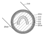
- FIG. 4 is a diagram illustrating an example of a cross section of a rim to which the sensor unit according to the first embodiment is attached.
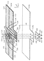
- FIG. 5 is an exploded perspective view of the electrode connection structure according to the first exemplary embodiment.
- FIG. 6 is a diagram showing a central portion of the sensor unit in the first embodiment.
- FIG. 7 is a cross-sectional view showing a cross section of the sensor section taken along line AA of FIG.
- FIG. 8 is a diagram illustrating an example of a portion where the metal wire is sandwiched in the first embodiment.
- FIG. 9 is a diagram illustrating another example of a portion where the metal wire is sandwiched in the first embodiment.
- FIG. 10 is a diagram illustrating another example of the portion where the metal wire is sandwiched in the first embodiment.
- FIG. 11 is a rear view of the grip sensor according to the second embodiment.
- FIG. 12 is an exploded perspective view of the electrode connection structure according to the second embodiment.
- FIG. 13 is a diagram illustrating a central portion of the sensor unit according to the second embodiment.
- FIG. 14 is a cross-sectional view showing a cross section of the sensor section taken along line BB in FIG.
- FIG. 15 is a diagram illustrating an example of a portion where a metal wire is sandwiched in the second embodiment.
- FIG. 16 is a diagram illustrating another example of a portion where a metal wire is sandwiched in the second embodiment.
- FIG. 17 is a diagram illustrating another example of a portion where a metal wire is sandwiched in the second embodiment.
- FIG. 18 is a front view of the grip sensor in the third embodiment.
- FIG. 19 is a rear view of the grip sensor according to the third embodiment.
- FIG. 20 is an exploded perspective view of the electrode connection structure according to the third embodiment.
- FIG. 21 is a diagram illustrating a central portion of the sensor unit according to the third embodiment.
- 22 is a cross-sectional view showing a cross section of the sensor section taken along the line CC of FIG.
- FIG. 23 is a diagram illustrating a part of the electrode connection
- An electrode connection structure includes a first base material, a first electrode layer and a second electrode layer formed on one surface of the first base material, and the one surface of the first base material.
- a second base material disposed on a surface opposite to the first base member, a first fastening member for fastening one end of the first electric wire to the first base material and the second base material, and an end of the second electric wire
- a second fastening member for fastening to the first base material and the second base material
- the first fastening member comprises the first electrode layer, the first base material, and the second base material.
- the base and the first shaft portion inserted into the first through-hole penetrating the insulating member, the first electrode layer, the first base material, the second base material, and the insulating member, respectively.
- Two first clamping portions arranged on the first shaft portion so as to sandwich the periphery of the first through hole in the axial direction of the first shaft portion.
- the second fastening member includes a second shaft portion that is inserted into a second through hole that penetrates the second electrode layer, the first base material, the second base material, and the insulating member, and the second electrode.
- the second shaft portion is sandwiched in the axial direction of the second shaft portion around the second through hole in each of the layer, the first base material, the second base material, and the insulating member.
- the insulating member may be a resin sheet.
- the insulating member may be a rubber sheet.
- the insulating member may be a nonwoven fabric.
- the insulating member may be a metal sheet having an insulating surface.
- the insulating member is sandwiched together with the first base member and the second base member by the two first sandwiching portions of the first fastening member and the two second sandwiching portions of the second fastening member,
- the mechanical connection strength of the electrode connection structure can be increased, and the electrode connection structure can be made difficult to break.
- the insulating member is held together with the first base material and the like by the two first holding portions of the first fastening member fixed to one end (specifically, the cable terminal) of the first electric wire such as a cable.
- the insulating member is held together with the first base material by the two second holding portions of the second fastening member fixed to one end (specifically, the cable terminal) of the second electric wire such as another cable.
- the insulating member is pulled.
- the first electric wire for example, cable
- the first base material and the second base material are reinforced, and the first electric wire is provided.
- the insulating member can suppress the movement of the first shaft portion of the first fastening member fixed to one end of the first fastening member. Even if the second electric wire is pulled, the insulating member can similarly suppress the movement of the second shaft portion of the second fastening member fixed to one end of the second electric wire.
- the insulating member may be disposed between the second base material, one of the two first sandwiching portions, and one of the two second sandwiching portions.
- an insulating member is arrange
- the electrode connection structure further includes a first metal wire and a second metal wire that are fixed to the second base material, respectively, and the two first sandwiching portions include the first electrode layer, Along with the first base material, the second base material, and the insulating member, the first metal wire fixed to the second base material is sandwiched in the axial direction of the first shaft portion, and the two second The two sandwiching portions include the second electrode layer, the first base material, the second base material, and the insulating member together with the second metal wire fixed to the second base material in the second axis. You may clamp in the axial direction of a part.
- the 1st metal wire currently fixed to the 2nd substrate is pinched with the 1st substrate etc. by the 1st fastening member, the mechanical connection strength of an electrode connection structure can be raised further. It is possible to make the electrode connection structure difficult to break. That is, the first metal wire fixed to the second base material is clamped by the two first clamping portions of the first fastening member fixed to one end (specifically, the cable terminal) of the first electric wire such as a cable. Has been. Therefore, for example, when a force is applied to the first shaft portion of the first fastening member fixed to one end of the first electric wire by pulling the first electric wire (for example, a cable), the first metal wire is The tensile stress is received.
- the 2nd substrate will be reinforced and the 1st axis part of the 1st fastening member currently fixed to the end of the 1st electric wire
- the movement of the first metal wire can be suppressed.
- it can suppress that the periphery of the through-hole in a 1st electrode layer, a 1st base material, and a 2nd base material is torn by the 1st axial part.
- the second metal wire fixed to the second base material is also held together with the first base material by the second fastening member. Therefore, the mechanical connection strength of the electrode connection structure can be further increased by the second metal wire, and the electrode connection structure can be hardly damaged.
- first metal wire and the second metal wire may be the same metal wire or different metal wires that are electrically insulated from each other.
- the first base material includes a first main base material and a first convex portion protruding from the first main base material, and the second base material faces the first main base material.
- the second convex portion is inserted into the first through hole penetrating the insulating member, and the second shaft portion of the second fastening member includes the second electrode layer, the first convex portion, and the second convex portion.
- the first metal wire and the second metal wire may be fixed to the second main base material, inserted into the second through hole penetrating the insulating member.
- the 1st metal wire and the 2nd metal wire are being fixed to the 2nd main substrate, even if the 1st electric wire or the 2nd electric wire is pulled, the 1st convex part and the 2nd convex part are the 1st It is possible to suppress tearing from the first main base material and the second main base material.
- Each of the first metal wire and the second metal wire has a substantially U-shaped folded portion, and both ends of the folded portion are fixed to the second main base material, and a central portion of the folded portion. Is fixed to the second convex portion, and the first shaft portion of the first fastening member or the second shaft portion of the second fastening member may be disposed inside the folded portion.
- the 1st axis part or the 2nd axis part is arranged inside the return part, when the 1st electric wire or the 2nd electric wire is pulled, it is outside with respect to the 1st axis part or the 2nd axis part. Even if a strong force is applied to the arm, the substantially U-shaped folded portion can sufficiently withstand the force. As a result, the mechanical connection strength of the electrode connection structure can be further increased.
- Each of the first metal wire and the second metal wire whose surfaces are electrically insulated is a heater element that generates heat when current flows through the metal wire and warms the electrode connection structure. Also good.
- the electrode connection structure when the electrode connection structure is attached to the rim of the steering wheel, for example, the rim can be warmed. As a result, a driver of a vehicle equipped with the steering wheel can comfortably grip the rim even when the interior of the vehicle is cold.
- first metal line and the second metal line are each a disturbance for detecting disturbance noise with respect to a signal detected in the first electrode layer and the second electrode layer. It may be a noise detection electrode.
- one of the two first sandwiching portions sandwiches the conductive first nonwoven fabric with the first electrode layer, and one of the two second sandwiching portions is electrically conductive.
- a second nonwoven fabric may be sandwiched between the second electrode layers.
- a 1st nonwoven fabric is arrange
- the 1st nonwoven fabric is electroconductivity, the electrical signal from a 1st electrode layer can be appropriately transmitted to 1st electric wires, such as a cable, via a 1st nonwoven fabric.
- the second nonwoven fabric is arranged as a buffer material, so that the occurrence of breakage of the second electrode layer can be suppressed, and the electric signal from the second electrode layer is appropriately transmitted to the second electric wire. Can do.
- an electrode connection structure includes a first base material, an electrode layer formed on one surface of the first base material, and a side opposite to the one surface of the first base material.
- a second base material disposed on the surface; a metal wire fixed to the second base material; and a fastening member for fastening one end of the electric wire to the first base material and the second base material.
- the fastening member includes: a shaft portion inserted into a through-hole penetrating the electrode layer, the first base material, and the second base material; and the electrode layer, the first base material, and the second base material.
- Each of the electric wires is electrically connected to the electrode layer, and the two ends of the wire are electrically connected to the electrode layer.
- the two clamping portions are fixed to the fastening member in a connected state, and the two clamping portions are shared with the electrode layer, the first base material, and the second base material.
- the metal wire is fixed to the second substrate, sandwiched in the axial direction.
- the metal wire fixed to the 2nd base material is clamped with the 1st base material etc. by two clamping parts of a fastening member, the mechanical connection strength of an electrode connection structure can be raised. It is possible to make the electrode connection structure difficult to break. That is, the metal wire fixed to the second base material is clamped by two clamping portions of the fastening member that is fixed to one end (specifically, a cable terminal) of an electric wire such as a cable. Therefore, for example, when the electric wire (for example, cable) is pulled and a force is applied to the shaft portion of the fastening member fixed to one end of the electric wire, the metal wire receives the tensile stress.
- the electric wire for example, cable
- the metal wire is fixed to the second base material, the second base material is reinforced, and the metal wire suppresses the movement of the shaft portion of the fastening member fixed to one end of the electric wire. be able to. As a result, it can suppress that the periphery of the through-hole in an electrode layer, a 1st base material, and a 2nd base material is torn by the axial part.
- the electrode connection structure may further include an insulating member that is disposed between the metal wire and one of the two sandwiching portions and is sandwiched in the axial direction by the two sandwiching portions.
- the insulating member may be a resin sheet.
- the insulating member may be a metal washer having an insulating surface.
- the insulating member is arranged as a cushioning material between the metal wire and one of the two holding portions, even if the holding portion strongly presses the metal wire to hold the metal wire, the metal The occurrence of wire breakage can be suppressed. As a result, even if the metal wire is covered, it can be suppressed that the coating is peeled off.
- the electrode connection structure further includes a third fastening member for fastening one end of the third electric wire to the first base material and the second base material, and the first electric wire and the second electric wire. And a binding member that binds at least one of the third electric wire and the third electric wire.
- the electrode connection structure further includes a metal wire fixed to the second base material, and the third fastening member is electrically and structurally configured so that one end of the third electric wire is connected to one end of the metal wire.
- the third electric wire may be fastened to the first base material and the second base material by being connected to each other.
- the binding member thereby, at least one of the first electric wire and the second electric wire and the third electric wire are bound by the binding member. Therefore, even if the third electric wire is pulled, the tensile force is prevented from being transmitted to the third fastening member, and the tensile force is transmitted to the first fastening member and the second fastening member having high mechanical strength. Can do. As a result, the second base material can be prevented from being torn by the third fastening member and the metal wire.
- the electrode connection structure further includes another fastening member for fastening one end of another electric wire different from the electric wire to the first base material and the second base material, the electric wire and the other electric wire.
- the other fastening member fastens the other electric wire to the first base material and the second base material by electrically and structurally connecting one end of the other electric wire to one end of the metal wire. May be.
- the electric wire and the other electric wire are bound by the binding member. Therefore, even if another electric wire is pulled, the tensile force can be prevented from being transmitted to the other fastening member, and the tensile force can be transmitted to the fastening member having a high mechanical strength. As a result, the second base material can be prevented from being torn by other fastening members and metal wires.
- the second base material is disposed on a surface opposite to the one surface of the first base material having the one surface on which the first electrode layer and the second electrode layer are formed. Then, an insulating member is disposed on the second base material, and a first fastening member having a first shaft portion and two first holding portions disposed on the first shaft portion is used to connect one end of the first electric wire. One end of the second electric wire by a second fastening member fastened to the first base material and the second base material and having a second shaft portion and two second sandwiching portions disposed on the second shaft portion.
- the first shaft portion is inserted into the first through hole, and the first electrode layer, the first base material, the second base material, and the insulating member are inserted.
- the periphery of the first through hole in each is sandwiched in the axial direction of the first shaft portion by the two first sandwiching portions, and one end of the first electric wire is electrically connected to the first electrode layer
- the second penetration member that is fixed to the first fastening member in a state where the second fastening member is engaged, and penetrates the second electrode layer, the first base material, the second base material, and the insulating member in the fastening by the second fastening member.
- the second shaft portion is inserted into the hole, and the two second through holes in each of the second electrode layer, the first base material, the second base material, and the insulating member are inserted into the two second holes.
- the two clamping parts are clamped in the axial direction of the second shaft part, and one end of the second electric wire is fixed to the second fastening member while being electrically connected to the second electrode layer.
- the second base material is disposed on a surface opposite to the one surface of the first base material having the one surface on which the electrode layer is formed, and the metal wire is disposed on the surface Fastening one end of the electric wire to the first base material and the second base material by a fastening member fixed to the second base material and having a shaft portion and two sandwiching portions disposed on the shaft portion, In fastening by a fastening member, the shaft portion is inserted into a through hole that penetrates the electrode layer, the first base material, and the second base material, and the electrode layer, the first base material, and the second base material are inserted.
- the periphery of the through hole in each of the two is clamped in the axial direction of the shaft portion by the two clamping portions, and one end of the electric wire is fixed to the fastening member in a state of being electrically connected to the electrode layer And the two clamping parts together with the electrode layer, the first base material and the second base material The metal wire is fixed to the second substrate, sandwiched in the axial direction.
- each figure is a schematic diagram and is not necessarily shown strictly. Moreover, in each figure, the same code
- expressions such as a substantially T-shape are used. For example, substantially the same not only means that they are completely the same, but also means that they are substantially the same, that is, they contain an error of, for example, a few percent. Moreover, substantially the same means in the range which can show the effect by this indication. The same applies to expressions using other “abbreviations”.
- FIG. 1 is a diagram showing an example of a vehicle compartment in which a grip sensor having an electrode connection structure according to the present embodiment is arranged.
- the vehicle 1 includes a steering wheel 200, a speaker 301, and a display device 302 such as a liquid crystal display.
- the speaker 301 and the display device 302 are configured as an alerting device, for example.
- the steering wheel 200 is for steering the vehicle 1.
- the steering wheel 200 includes a rim 210 having a ring shape, a substantially T-shaped spoke 202 integrally formed on the inner peripheral surface of the rim 210, and a horn switch (not shown) disposed at the center of the spoke 202. And a horn switch cover 203 for covering the above.
- the grip sensor 100 is a device that detects gripping of the steering wheel 200 by a hand, and is provided in the steering wheel 200 of the vehicle 1 as shown in FIG. Specifically, the grip sensor 100 includes a sensor unit 110 embedded in the rim 210 of the steering wheel 200, a control circuit unit 120 that detects gripping based on a signal from the sensor unit 110, and a control circuit that controls the sensor unit 110. And a harness 130 that is electrically connected to the portion 120. The control circuit unit 120 is embedded in the spoke 202, for example. Such a grip sensor 100 detects the grip of the rim 210 of the steering wheel 200.
- Part or all of the sensor unit 110 in the present embodiment is configured as an electrode connection structure.
- the sensor unit 110 has at least one electrode. With this electrode, the capacitance changes depending on whether or not the driver of the vehicle 1 is holding the rim 210 of the steering wheel 200.
- the control circuit unit 120 measures a value corresponding to the capacitance of the electrode, and detects gripping of the rim 210 by the driver's hand based on the value.
- control circuit part 120 makes a warning device perform a warning to a driver, when grasping is not detected although vehicles 1 are driven.
- the speaker 301 of the alerting device alerts the driver with a warning sound or voice.
- the display device 302 displays a warning message that prompts the driver to hold the steering wheel 200 firmly. Thereby, a traffic accident can be reduced.
- FIG. 2 is a diagram illustrating an example of how the sensor unit 110 is wound around the rim 210 in the present embodiment.
- the sensor part 110 is a sheet-like structure having elasticity, flexibility and ductility as a whole, and is formed in a long shape.
- the longitudinal direction of the sensor unit 110 is referred to as a Y-axis direction, and a direction perpendicular to the Y-axis direction on a plane parallel to the sensor unit 110 is referred to as an X-axis direction.
- one end side (left end side in FIG. 2) of the sensor unit 110 in the Y-axis direction is referred to as a negative side, and the other end side (right end side in FIG. 2) is referred to as a positive side.
- one end side (lower end side in FIG. 2) of the sensor unit 110 in the X-axis direction is referred to as a negative side
- the other end side (upper end side in FIG. 2) is referred to as a positive side.
- a direction perpendicular to the surface of the sensor unit 110 is referred to as a Z-axis direction.
- One in the Z-axis direction (the back side in FIG. 2) is referred to as a negative side, and the other in the Z-axis direction (the front side in FIG. 2) is referred to as a positive side.
- the sensor unit 110 is attached to the rim 210 of the steering wheel 200. At this time, the sensor unit 110 is wound around the rim 210 so that a ring is formed by the sensor unit 110. And both ends Ea and Eb of the sensor unit 110 are disposed so as to be substantially opposed to each other.
- the sensor unit 110 when the sensor unit 110 is wound around the rim 210 of the steering wheel 200, the sensor unit 110 can be wound while being stretched. Therefore, as described above, the sensor unit 110 has elasticity, flexibility, and ductility, and is stretched by about 15%, for example.
- FIG. 3A is a front view of the grip sensor 100 in the present embodiment.
- FIG. 3B is a rear view of the grip sensor 100 according to the present embodiment.
- the grip sensor 100 includes the sensor unit 110, the control circuit unit 120, and the harness 130 as described above.
- the sensor unit 110 includes a first base material 111, a second base material 112, four electrode layers 113, four fastening members 114, and two metal wires 115. And.
- the first substrate 111 is formed in a long sheet shape by a material having elasticity, flexibility and ductility.
- the first substrate 111 is made of a synthetic resin such as polyethylene terephthalate (PET).
- Each of the four electrode layers 113 is formed on one surface, for example, the surface of the first base material 111, as shown in FIG. 3A. Note that the surface is, for example, a positive surface of the first base material 111 in the Z-axis direction. These electrode layers 113 are formed on the surface of the first base material 111 by, for example, nickel plating.
- the sensor unit 110 includes four electrode layers 113.
- the number of the electrode layers 113 may be one, two, or three, and four or more. Also good.
- the electrode layer 113 may have any form as long as it functions as an electrode. That is, the electrode layer 113 may be a solid electrode, a sheet-like or plate-like electrode, or a wiring pattern.
- the shape, number, arrangement pattern, and the like of the electrode layer 113 shown in FIGS. 3A and 3B are examples, and any shape, number, and arrangement pattern may be used.
- the first base material 111 may be separated into four parts.
- the electrode layer 113 is formed in each of the four portions. Further, the electrode layer 113 may be formed not only on the respective surfaces of the four separated parts but also on the whole.
- the electrode layer 113 may be formed on the entire fibers of the woven fabric. In this case, the first base material 111 on which the electrode layer 113 is formed is configured as a conductive cloth.
- the second base material 112 is disposed on the surface opposite to the one surface of the first base material 111, that is, on the back surface.
- the second base material 112 is configured as a long mat made of a material having elasticity, flexibility, and ductility (for example, polyethylene).
- the first base material 111 and the second base material 112 are stacked such that, for example, when viewed from the front or the back, the peripheral edges thereof coincide with each other, and a tape having an adhesive layer such as a double-sided tape, or an adhesive or an adhesive. Is glued by. In the following description, a configuration using a double-sided tape will be described.
- Each of the four fastening members 114 is connected to one end (for example, a cable terminal) of the cable 116 that is an electric wire for electrically connecting to the electrode layer 113 corresponding to the fastening member 114 with the first base member 111 and the second base member. It is a member for fastening to the material 112.
- These fastening members 114 are, for example, rivets.
- the fastening member 114 is not limited to a rivet, and may be a member made of a bolt and a nut as long as the first base material 111 and the second base material 112 can be fastened together. May be.
- the electrode layer 113 is electrically connected to the control circuit unit 120 via the cable 116 by the fastening member 114. As shown in FIGS. 3A and 3B, a bundle of a plurality of (here, four) cables 116 and metal wires 115 is a harness 130.
- Each of the two metal wires 115 is fixed to the surface of the second substrate 112 opposite to the first substrate 111.
- the metal wire 115 is sewn to the second base material 112 so that a zigzag pattern is formed.
- the metal wire 115 is, for example, a resin-coated conductive wire and is used as a heater element. That is, the surface of the metal wire 115 is electrically insulated, and both ends of the metal wire 115 are electrically connected to the control circuit unit 120.
- the metal wire 115 When a current flows through the metal wire 115 by the control circuit unit 120, the metal wire 115 generates heat. Due to this heat generation, the metal wire 115 warms the sensor unit 110. As a result, the rim 210 of the steering wheel 200 can be warmed. Therefore, the driver of the vehicle 1 can comfortably grip the rim 210 even when the inside of the vehicle is cold.
- the electrode connection structure in the present embodiment may be the entire sensor unit 110 or a part of the sensor unit 110.
- a part of the sensor unit 110 is a structure including, for example, a fastening member 114 in the sensor unit 110 and a periphery where the fastening member 114 is disposed.
- FIG. 4 is a diagram illustrating an example of a cross section of the rim 210 to which the sensor unit 110 is attached.
- the rim 210 includes a metal core 201b that is a metal annular core, and a resin layer 201a made of urethane resin or the like that covers the metal core 201b.
- each component of the sensor unit 110 is arranged in the order of the metal wire 115, the second base material 112, the first base material 111, and the electrode layer 113 from the resin layer 201a side to the outside.
- the surface on the electrode layer 113 side of the sensor unit 110 wound in this way is covered with a surface layer 201c made of leather, wood, resin, or the like.
- the electrode layer 113 disposed on the rim 210 forms a capacitance with the core bar 201b.
- a capacitance is also formed between the electrode layer 113 and the hand. Therefore, the control circuit unit 120 can detect the grip of the rim 210 by the hand from the signal output from the electrode layer 113 according to the electrostatic capacity.
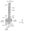
- FIG. 5 is an exploded perspective view of the sensor unit 110.
- the first base material 111 on which the four electrode layers 113 are formed has an elongated first main base material 111a and four first convex portions 111b protruding from the first main base material 111a.
- each of the four first protrusions 111b is arranged along the Y-axis direction at the approximate center of the X-axis direction negative side of the first main base material 111a, and on the X-axis direction negative side. It protrudes.
- Each of the four electrode layers 113 is formed in a range including a part of the first main base material 111 a and at least a part of the first convex part 111 b corresponding to the electrode layer 113. Further, a through hole 105 is formed in a portion where the electrode layer 113 of each of the four first protrusions 111b is formed.
- the 2nd base material 112 protrudes from the 2nd main base material 112a which opposes the 1st main base material 111a, and the 2nd main base material 112a, and the 4th 2nd convexity which counters each of the four 1st convex parts 111b.
- Part 112b each of the four second convex portions 112b is along the Y-axis direction at the approximate center of the X-axis direction negative side of the second main base material 112a, like the four first convex portions 111b. And protrudes to the X axis direction negative side. Further, a through hole 105 is formed in each of the four second convex portions 112b.
- 1st base material 111 and 2nd base material 112 are piled up via a double-sided tape in the state arranged so that through-hole 105 currently formed in each base material may connect.
- the back surface of the first base material 111 that is, the surface on which the electrode layer 113 is not formed
- the back surface of the second base material 112 that is, the surface on which the metal wire 115 is not sewn are formed by the double-sided tape. Glued.
- the 1st base material 111 and the 2nd base material 112 are joined.
- the through-hole 105 may be formed by making a hole after the first base material 111 and the second base material 112 are overlapped via a double-sided tape.
- the set is referred to as an electrode extraction unit 10. That is, the sensor unit 110 has four electrode extraction units 10.
- the cable 116 that is an electric wire, and the cable 116
- a cable terminal 117 connected to one end is used.
- the cable 116 is, for example, an insulation-coated copper wire.
- the cable terminal 117 is a ring-shaped (or round) crimp terminal.
- the cable terminal 117 is fastened to the first base material 111 and the second base material 112 by the fastening member 114.
- a conductive nonwoven fabric 102 and a pair of washers 101 are used.
- the conductive nonwoven fabric 102 is a conductive nonwoven fabric.
- the conductive nonwoven fabric 102 has elasticity, flexibility, and ductility, and is configured by performing nickel plating on a synthetic resin nonwoven fabric.
- the conductive nonwoven fabric 102 is also formed with a through hole 105.
- Such a conductive nonwoven fabric 102 is disposed for each of the four electrode lead portions 10. That is, the conductive nonwoven fabric 102 is disposed so as to overlap the electrode layer 113 of the electrode leading portion 10 so that the conductive nonwoven fabric 102 and each through hole 105 of the electrode leading portion 10 communicate with each other.
- the pair of washers 101 are arranged so that each of the four electrode lead-out portions 10 sandwiches the electrode lead-out portion 10 and the conductive nonwoven fabric 102 in the Z-axis direction.
- the washer 101 is made of metal and is formed by applying nickel plating to copper.
- the cable terminal 117 is arranged for each of the four electrode lead portions 10. That is, the cable terminal 117 is disposed on the positive side in the Z-axis direction of the washer 101 so that the conductive nonwoven fabric 102 and the washer 101 are sandwiched between the electrode layer 113 of the electrode lead-out portion 10. At this time, the cable terminal 117 is disposed so that the hole of the ring of the cable terminal 117, the hole of the pair of washers 101, and the through holes 105 of the conductive nonwoven fabric 102 and the electrode lead-out portion 10 communicate with each other.
- the fastening member 114 is arrange
- the tip of the inserted fastening member 114 is caulked in a state of protruding from the washer 101 on the negative side in the Z-axis direction. That is, by this caulking, the tip of the fastening member 114 is plastically deformed and crushed.
- the cable terminal 117 which is one end of an electric wire is electrically connected to the electrode layer 113 of the electrode lead-out part 10 via the conductive nonwoven fabric 102 and the washer 101.
- the electrode connection structure in the present embodiment includes such an electrode lead-out portion 10, a fastening member 114 corresponding to the electrode lead-out portion 10, a conductive nonwoven fabric 102, a cable terminal 117, a pair of washers 101, and a metal wire 115. including.
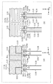
- FIG. 6 is a diagram showing a central portion of the sensor unit 110. Specifically, FIG. 6A shows a front center portion of the sensor unit 110, and FIG. 6B shows a back center portion of the sensor unit 110.
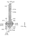
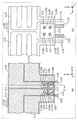
- FIG. 7 is a cross-sectional view showing a cross section taken along line AA of the sensor unit 110 shown in FIG.
- the fastening member 114 has a shaft portion 114c and two sandwiching portions 114a and 114b disposed on the shaft portion 114c.
- the shaft portion 114 c is inserted into the through hole 105 of the electrode lead-out portion 10, that is, the through hole 105 that penetrates the electrode layer 113, the first base material 111, and the second base material 112.
- the two sandwiching portions 114a and 114b are arranged so that the shaft portion 114c is sandwiched in the axial direction of the shaft portion 114c around the through hole 105 in each of the electrode layer 113, the first base material 111, and the second base material 112. Is arranged.
- the clamping portion 114a is a rivet head
- the shaft portion 114c is a rivet barrel
- the clamping portion 114b is crimped at the tip of the barrel. It is a part formed like a head.
- the first base material 111 and the second base material 112 are bonded by a double-sided tape 103.
- the clamping portions 114a and 114b of the fastening member 114 are, as shown in FIGS. 6 and 7, the electrode layer 113, the first base material 111, and the second base material 112.
- the metal wire 115 fixed to the second base material 112 is sandwiched in the Z-axis direction. That is, the sandwiching portions 114a and 114b sandwich the metal wire 115 sewn to the second base material 112 together with the electrode layer 113, the first base material 111, and the like.
- the fastening member 114 fastens the metal wire 115 together with the electrode layer 113, the first base material 111, and the like.
- the mechanical connection strength of the electrode connection structure including the electrode lead-out portion 10 can be increased.
- the metal wire 115 receives the tensile stress. It will be. Therefore, as shown in FIG. 3B, the metal wire 115 is firmly fixed over the entire second base material 112, so that the second base material 112 is reinforced and fastened to the cable terminal 117.
- the movement of the shaft portion 114c of the member 114 can be suppressed by the metal wire 115. As a result, it is possible to suppress the periphery of the through hole 105 in the electrode layer 113, the first base material 111, and the second base material 112 from being torn by the shaft portion 114c.
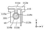
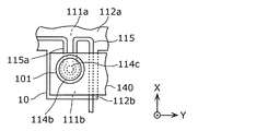
- the portion of the metal wire 115 sandwiched by the sandwiching portions 114a and 114b is in the second convex portion 112b as shown in FIG. 6B.
- the other part of the metal wire 115 is fixed to the second main base material 112a as shown in FIG.
- the metal wire 115 is fixed to the second main base material 112a, even if the cable 116 connected to the cable terminal 117 is pulled, the first convex portion 111b and the second convex portion 112b are It is possible to suppress tearing from the main base material 111a and the second main base material 112a.
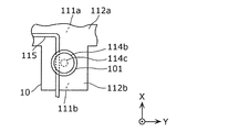
- FIG. 8 is a diagram illustrating an example of a portion where the metal wire 115 is sandwiched. Specifically, FIG. 8 shows an enlarged view of the portion of the metal wire 115 around the clamping portion 114b of the fastening member 114 shown in FIG.
- the metal wire 115 in the present embodiment has a substantially U-shaped folded portion 115a. Both ends of the folded portion 115a are fixed to the second main base material 112a. Moreover, the center part of the folding
- the substantially U-shaped folded portion 115a of the metal wire 115 is used. It can withstand that force. As a result, the mechanical connection strength of the electrode connection structure can be further increased.
- FIG. 9 is a diagram showing another example of a portion where the metal wire 115 is sandwiched.
- the metal wire 115 in the present embodiment has a substantially U-shaped folded portion 115a as shown in FIG. 8, but may not have such a folded portion 115a.
- the portion where the metal wire 115 is sandwiched may be formed in a substantially I shape as shown in FIG. Even in such a shape, the metal wire 115 reinforces the second convex portion 112b, and the metal wire 115 is sandwiched between the sandwiching portions 114a and 114b. Connection strength can be increased.
- FIG. 10 is a diagram showing another example of a portion where the metal wire 115 is sandwiched.
- the metal wire 115 in the present embodiment has a substantially U-shaped folded portion 115a as shown in FIG. 8, but the substantially U-shape is, for example, as shown in FIG. It may be. That is, it is defined that the substantially U-shaped folded portion 115a includes the shape of FIG. Even in such a shape, the substantially U-shaped folded portion 115a of the metal wire 115 can sufficiently withstand the force. As a result, the mechanical connection strength of the electrode connection structure can be further increased.
- the metal wire 115 fixed to the second base material 112 is moved together with the first base material 111 and the like by the two clamping portions 114a and 114b of the fastening member 114. It is pinched. Therefore, the mechanical connection strength of the electrode connection structure can be increased. As a result, the electrode connection structure can be hardly damaged.
- the electrode layer 113 it is not necessary to cause the electrode layer 113 to protrude from the ends of the first base material 111 and the second base material 112 when the sensor part 110 is viewed from the front or the back surface. 110 can be generated efficiently. Specifically, a number of electrode layers 113 required for the plurality of sensor units 110 are formed on a base material for cutting out the plurality of first base materials 111, and a plurality of first substrates are formed from the base material. If the material 111 is cut out, a plurality of sensor units 110 can be efficiently generated.
- the number of metal wires 115 required for the plurality of sensor units 110 is sewn to the base material for cutting out the plurality of second base materials 112, and each of the portions corresponding to the metal wires 115 is sewn.
- the first base material 111 on which the electrode layer 113 is formed may be attached. And if the some 2nd base material is cut out from the base material, the some sensor part 110 can be produced
- the surface of the washer 101 disposed on the clamping portion 114b side of the fastening member 114 may be covered with an insulating material.
- the electrode connection structure in the present embodiment further includes an insulating member with respect to the configuration of the electrode connection structure in the first embodiment.
- an insulating member with respect to the configuration of the electrode connection structure in the first embodiment.
- FIG. 11 is a rear view of the grip sensor 100 according to the present embodiment.
- the grip sensor 100 includes a sensor unit 110, a control circuit unit 120, and a harness 130 as in the first embodiment.
- the sensor unit 110 includes two insulating members 140.
- Each of the two insulating members 140 is disposed on the surface of the second base material 112 so as to cover a part of the metal wire 115 around the two fastening members 114.
- the surface of the second substrate 112 is the surface of the second substrate 112 opposite to the first substrate 111 side.
- Such an insulating member 140 is an electrically insulating member, for example, a resin sheet, a rubber sheet, a non-woven fabric, or a metal sheet having an insulating surface.
- FIG. 12 is an exploded perspective view of the sensor unit 110 in the present embodiment.
- Each of the two insulating members 140 is disposed so as to cover the surfaces (that is, the surfaces on the negative side in the Z-axis direction) of the two second convex portions 112b of the second base material 112. At this time, the insulating member 140 is disposed such that the two through holes 105 formed in the insulating member 140 communicate with the through holes 105 of the two second convex portions 112b adjacent to each other. The insulating member 140 is held together with the two electrode lead portions 10 by the two fastening members 114.
- the pair of washers 101 corresponding to the electrode lead-out portion 10 is connected to the conductive nonwoven fabric 102, the electrode lead-out portion 10, and the insulating member in each of the two electrode lead-out portions 10.
- 140 is arranged so as to be sandwiched in the Z-axis direction.
- the cable terminal 117 and the fastening member 114 are arranged for each of the two electrode lead portions 10.
- the axis of the fastening member 114 used for one of the two electrode lead-out portions 10 is inserted into the through hole 105 penetrating the electrode layer 113, the first convex portion 111b, the second convex portion 112b, and the insulating member 140. Is done.
- the axis of the fastening member 114 used for the other of the two electrode lead-out portions 10 is another through-hole penetrating the other electrode layer 113, the first convex portion 111b, the second convex portion 112b, and the insulating member 140. 105 is inserted.
- the axis of the fastening member 114 extends from the positive side to the negative side in the Z-axis direction, the hole of the ring of the cable terminal 117, the hole of the pair of washers 101, the conductive nonwoven fabric 102, the electrode lead-out portion 10 and the respective through holes 105 of the insulating member 140. Further, the tip of the inserted fastening member 114 is crimped in a state of protruding from the washer 101 on the Z axis direction negative side.
- the cable terminal 117 which is one end of an electric wire is electrically connected to the electrode layer 113 of the electrode lead-out part 10 via the conductive nonwoven fabric 102 and the washer 101.
- the electrode connection structure according to the present embodiment includes such an electrode lead-out portion 10, a fastening member 114 corresponding to the electrode lead-out portion 10, a conductive nonwoven fabric 102, a cable terminal 117, a pair of washers 101, an insulating member 140, and a metal Line 115.
- FIG. 13 is a diagram showing a central portion of the sensor unit 110 in the present embodiment. Specifically, FIG. 13A shows the front center portion of the sensor unit 110, and FIG. 13B shows the back center portion of the sensor unit 110.
- FIG. 14 is a cross-sectional view showing a cross section taken along line BB of the sensor unit 110 shown in FIG.
- the shaft portion 114 c of the fastening member 114 is inserted into the conductive nonwoven fabric 102, the electrode lead-out portion 10, and the through hole 105 of the insulating member 140.
- the two sandwiching portions 114a and 114b are arranged on the shaft portion 114c so as to sandwich the periphery of the through hole 105 in each of the conductive nonwoven fabric 102, the electrode lead-out portion 10, and the insulating member 140 in the axial direction of the shaft portion 114c. ing.
- the fastening member 114 is a rivet
- the clamping portion 114a is a rivet head
- the shaft portion 114c is a rivet trunk
- the clamping portion 114b is a trunk thereof. It is a part that is formed like a head when the tip of is crimped.
- the clamping portions 114 a and 114 b of the fastening member 114 are attached to the second base material 112 together with the electrode lead-out portion 10 as shown in FIGS. 13 and 14.
- the fixed metal wire 115 is clamped in the Z-axis direction.
- the metal wire 115 is formed by the washer 101 disposed on the sandwiching portion 114 b side of the pair of washers 101. It is strongly pressed against the second base material 112 side. As a result, when the washer 101 strongly hits the metal wire 115, the insulating coating formed on the surface of the metal wire 115 may be peeled off.
- the insulating member 140 is disposed so as to cover the metal wire 115, it is possible to suppress the washer 101 from coming into direct contact with the metal wire 115. As a result, the metal wire 115 can be prevented from being peeled off.
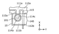
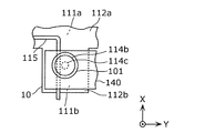
- FIG. 15 is a diagram illustrating an example of a portion where the metal wire 115 is sandwiched. Specifically, FIG. 15 shows an enlarged view of the portion of the metal wire 115 around the clamping portion 114b of the fastening member 114 shown in FIG. 16 and 17 are diagrams showing another example of a portion where the metal wire 115 is sandwiched.
- the metal wire 115 is sandwiched by the fastening member 114 as in the first embodiment, so that the mechanical connection strength of the electrode connection structure is increased. Can be raised. Furthermore, in this embodiment, since the insulating member 140 is disposed so as to cover the metal wire 115, it is possible to prevent the metal wire 115 from being peeled off. That is, the electrode connection structure in the present embodiment is disposed between the metal wire 115 and one of the two sandwiching portions 114a and 114b, and is insulated in the axial direction by the two sandwiching portions 114a and 114b. A member 140 is provided.
- the holding portion 114a or 114b holds the metal wire so as to hold the metal wire. Even if the 115 is strongly pressed, the occurrence of breakage of the metal wire 115 can be suppressed. As a result, even if the metal wire 115 is covered, it can be suppressed that the coating is peeled off.
- the electrode connection structure in the present embodiment further includes an insulating member 140 in addition to the configuration of the first embodiment.
- the insulating member 140 is held together with the two electrode lead portions 10 by the two fastening members 114. Therefore, the mechanical connection strength of the electrode connection structure can be further increased, and the electrode connection structure can be further prevented from being damaged. That is, the insulating member 140 is held together with the first base material 111 and the like by the two holding portions 114a and 114b of the fastening member 114 fixed to one end of the cable 116. Further, the insulating member 140 is sandwiched together with the first base material 111 and the like by the two sandwiching portions 114a and 114b of the other fastening member 114 fixed to one end of the other cable 116.
- the insulating member 140 receives the tensile stress. become.
- the insulating member 140 is held together with the first base material 111 and the second base material 112 by the other fastening members 114.
- the first base material 111 and the second base material 112 are reinforced. Therefore, the movement of the shaft portion 114 c of the fastening member 114 fixed to one end of the one cable 116 can be suppressed by the insulating member 140.
- the insulating member 140 can suppress the movement of the shaft portion 114 c of the other fastening member 114 fixed to one end of the cable 116. As a result, it is possible to suppress the periphery of the first through hole 105 in the electrode layer 113, the first base material, and the second base material from being torn by the shaft portion 114c.
- the electrode connection structure in the present embodiment includes the first metal wire 115 and the second metal wire 115 fixed to the second base material 112, respectively, as in the first embodiment.
- the two sandwiching portions 114 a and 114 b include the electrode layer 113, the first base material 111, the second base material 112, and the insulating member 140.
- the first metal wire 115 fixed to the second base material 112 is sandwiched in the axial direction of the shaft portion 114c.
- the two clamping portions 114a and 114b are fixed to the second base material 112 together with the other electrode layers 113, the first base material 111, the second base material 112, and the insulating member 140.
- the second metal wire 115 is sandwiched in the axial direction of the shaft portion 114c.
- the first metal line 115 and the second metal line 115 may be the same metal line, or may be mutually different metal lines that are electrically insulated.
- the first metal wire 115 fixed to the second base material 112 is sandwiched together with the first base material 111 by the one fastening member 114. Therefore, the mechanical connection strength of the electrode connection structure can be increased, and the electrode connection structure can be made difficult to break.
- the second metal wire 115 fixed to the second base material 112 is also held by the other fastening member 114 together with the first base material 111 and the like. Therefore, the second metal wire 115 can also increase the mechanical connection strength of the electrode connection structure and make it difficult to damage the electrode connection structure.
- the insulating member 140 is sandwiched between the two fastening members 114, but may be sandwiched between only one fastening member 114.
- the insulating member 140 may be a metal washer having an insulating surface.
- the electrode connection structure in this Embodiment is equipped with all the components of the electrode connection structure of Embodiment 1, not only the effect in the present Embodiment but the Embodiment 1 is included. There are also the same effects.
- Electrode connection structure in the present embodiment instead of clamping the metal wire 115 by the fastening member 114 as in the first embodiment, the insulating member 140 by the plurality of fastening members 114 is the same as in the second embodiment.
- the mechanical connection strength of the electrode connection structure is increased by clamping.
- FIG. 18 is a front view of the grip sensor 100 in the present embodiment.
- FIG. 19 is a rear view of the grip sensor 100 according to the present embodiment.
- the grip sensor 100 includes a sensor unit 110, a control circuit unit 120, and a harness 130 as in the first and second embodiments.
- the sensor unit 110 as shown in FIG. 18, two fastening members 114 are arranged in each of the X-axis direction and the Y-axis direction.
- the four fastening members 114 are arranged in a matrix composed of two columns in the X-axis direction and two rows in the Y-axis direction.
- one end side of each of the four electrode layers 113 formed on the first base material 111 protrudes to the negative side in the X-axis direction so that the four fastening members 114 are arranged in the above-described matrix shape. .
- the insulating member 140 is disposed on the surface of the second base material 112 (the surface on the Z axis direction negative side).
- the insulating member 140 is sandwiched by the four fastening members 114 together with the electrode layer 113, the first base material 111 and the second base material 112.
- the metal wire 115 is not sandwiched between the fastening members 114. Therefore, it can suppress that the coating
- FIG. 20 is an exploded perspective view of the sensor unit 110 in the present embodiment.
- the first base 111 has only one first convex portion 111b without including the four first convex portions 111b as in the first and second embodiments. That is, the 1st base material 111 has the elongate 1st main base material 111a and the 1st 1st convex part 111b which protrudes from the 1st main base material 111a. Specifically, the one first protrusion 111b protrudes from the approximate center of the X-axis direction negative side of the first main base material 111a to the X-axis direction negative side. One end side of each of the four electrode layers 113 is formed on the one first convex portion 111b. A through-hole 105 is formed in the four portions of the first convex portion 111b, that is, in the portion where one end of each of the four electrode layers 113 is formed.
- the second base material 112 has only one second convex portion 112b, like the first base material 111. That is, the second base material 112 includes a second main base material 112a that faces the first main base material 111a, and one second protrusion that protrudes from the second main base material 112a and faces one first convex portion 111b. Part 112b. Specifically, the one second convex portion 112b protrudes from the approximate center of the X-axis direction negative side of the second main base material 112a to the X-axis direction negative side, like the first convex portion 111b. Yes. Further, four through holes 105 are formed in the second convex portion 112b.
- the first base material 111 and the second base material 112 are overlapped with a double-sided tape in a state where the through holes 105 formed in the base materials are arranged to communicate with each other.
- the back surface of the first base material 111 and the back surface of the second base material 112 (that is, the surface on which the metal wire 115 is not sewn) are bonded with a double-sided tape.
- the 1st base material 111 and the 2nd base material 112 are joined.
- the through-hole 105 may be formed by making a hole after the first base material 111 and the second base material 112 are overlapped via a double-sided tape.
- these members are stacked in the order of the conductive nonwoven fabric 102, the washer 101, and the cable terminal 117 from the electrode layer 113 side. At this time, these members are arranged so that the respective holes communicate with each other.
- the insulating member 140 is disposed on the surface of the second convex portion 112 b of the second base material 112. Also at this time, the insulating member 140 is disposed such that the four through holes 105 of the insulating member 140 communicate with the four through holes 105 of the second convex portion 112b. And the washer 101 is arrange
- the shafts of the four fastening members 114 pass through the holes of the cable terminal 117 and the pair of washers 101, the electrode lead-out portion 10 and the insulating member 140, for example, from the positive side to the negative side in the Z-axis direction. It is inserted into the hole 105. Further, the tip of the inserted fastening member 114 is crimped in a state of protruding from the washer 101 on the Z axis direction negative side.
- FIG. 21 is a diagram showing a central portion of the sensor unit 110 in the present embodiment. Specifically, FIG. 21A shows the front center portion of the sensor unit 110, and FIG. 21B shows the back center portion of the sensor unit 110.
- FIG. 22 is a cross-sectional view showing a cross section taken along line CC of the sensor unit 110 shown in FIG.
- the shaft portion 114 c of the fastening member 114 is inserted into the respective holes of the cable terminal 117 and the washer 101, and further inserted into the conductive nonwoven fabric 102, the electrode lead-out portion 10, and the through hole 105 of the insulating member 140. Is done. Further, the shaft portion 114 c is inserted into a hole of the washer 101 disposed on the insulating member 140.
- the two sandwiching portions 114a and 114b are disposed on the shaft portion 114c. These two sandwiching portions 114a and 114b are arranged around the through hole 105 in the conductive nonwoven fabric 102, the electrode lead-out portion 10 and the insulating member 140 in the axial direction of the shaft portion 114c via the cable terminal 117 and the pair of washers 101. Pinch.
- the fastening member 114 is a rivet
- the clamping portion 114a is a rivet head
- the shaft portion 114c is a rivet trunk
- the clamping portion 114b is a trunk thereof. It is a part that is formed like a head when the tip of is crimped.
- the clamping portions 114a and 114b of the fastening member 114 are attached to the second base material 112 as shown in FIG. 21B and FIG.
- the fixed metal wire 115 is not sandwiched. That is, the metal wire 115 is not strongly pressed against the second base material 112 side by the sandwiching portion 114b and the washer 101. Thereby, it can suppress that the coating
- the insulating member 140 is sandwiched by the four fastening members 114 together with the electrode lead-out portion 10.
- the insulating member 140 is fastened together with the electrode lead-out portion 10 by four fastening members.
- the mechanical connection strength of the electrode connection structure including the electrode lead-out portion 10 can be increased.
- the insulating member 140 receives the tensile stress. It will be. Since the insulating member 140 is fastened together with the electrode lead-out portion 10 by the four fastening members 114 as described above, the second base material 112 is reinforced and fastened to the cable terminal 117.
- the insulating member 140 can suppress the movement of the shaft portion 114 c of the member 114. As a result, it is possible to suppress the periphery of the through hole 105 in the electrode layer 113, the first base material 111, and the second base material 112 from being torn by the shaft portion 114c.
- the electrode connection structure includes the four electrode layers 113 and the four fastening members 114.
- the number is not limited to four, and any number may be used as long as the number is two or more. It may be. That is, the electrode connection structure in the present embodiment includes at least two electrode layers 113, at least two fastening members 114 corresponding to the electrode layers 113, and an insulating member 140 sandwiched between the fastening members 114. Is provided.
- the at least two electrode layers 113 include, for example, the first electrode layer 113 and the second electrode layer 113 out of the four electrode layers 113 described above.
- the at least two fastening members 114 include, for example, the first fastening member 114 and the second fastening member 114 among the above-described four fastening members 114. By these fastening members 114, one ends of the cables 116 that are the first electric wire and the second electric wire are fastened to the first base material 111 and the second base material 112, respectively.
- the electrode connection structure in the present embodiment includes the first base 111, the first electrode layer 113 and the second electrode layer 113 formed on one surface of the first base 111, and the first base.
- the first fastening member 114 includes a first shaft portion 114c inserted into a first through hole 105 penetrating the first electrode layer 113, the first base material 111, the second base material 112, and the insulating member 140, and a first The first shaft portion so as to sandwich the periphery of the first through hole 105 in each of the electrode layer 113, the first base material 111, the second base material 112, and the insulating member 140 in the axial direction of the first shaft portion 114c. It has two 1st clamping parts 114a and 114b arrange
- the second fastening member 114 includes a second shaft portion 114c inserted into the second through hole 105 penetrating the second electrode layer 113, the first base material 111, the second base material 112, and the insulating member 140.
- the second electrode layer 113, the first base material 111, the second base material 112, and the insulating member 140 are each sandwiched around the second through hole 105 in the axial direction of the second shaft portion 114 c. It has two 2nd clamping parts 114a and 114b arrange
- One end of the cable 116 that is the first electric wire is fixed to the first fastening member 114 while being electrically connected to the first electrode layer 113, and one end of the cable 116 that is the second electric wire is fixed to the second electrode layer 113.
- the second fastening member 114 is fixed to the second fastening member 114 while being electrically connected to the second fastening member 114.
- the insulating member 140 includes the first base member 111 and the second base member 114 by the two first sandwiching portions 114a and 114b of the first fastening member 114 and the two second sandwiching portions 114a and 114b of the second fastening member 114. It is sandwiched together with the base material 112 and the like. Therefore, the mechanical connection strength of the electrode connection structure can be increased, and the electrode connection structure can be made difficult to break. That is, the insulating member 140 is made to be the first base material 111 by the two first holding portions 114a and 114b of the first fastening member 114 fixed to one end of the first electric wire such as the cable 116 (specifically, the cable terminal 117). Etc.
- the insulating member 140 is also formed by the two second clamping portions 114a and 114b of the second fastening member 114 fixed to one end (specifically, the cable terminal 117) of the second electric wire such as the other cable 116. It is sandwiched together with the base material 111 and the like. Therefore, for example, when the cable 116 which is the first electric wire is pulled and a force is applied to the first shaft portion 114c of the first fastening member 114 fixed to one end of the cable 116, the insulating member 140 is The tensile stress is received.
- the insulating member 140 is held together with the first base material 111 and the second base material 112 by the second fastening member 114.
- the insulating member 140 can suppress the movement of the first shaft portion 114c of the first fastening member 114 fixed to one end of the cable 116 that is the first electric wire. Even if the second electric wire as the other cable 116 is pulled, the insulating member 140 can similarly suppress the movement of the second shaft portion 114c of the second fastening member 114 fixed to one end of the second electric wire. it can. As a result, it is possible to suppress the periphery of the first through hole 105 in the first electrode layer 113, the first base material, and the second base material from being torn by the first shaft portion 114c. Similarly, it is possible to prevent the second electrode layer 113, the first base material, and the second base material from being torn around the second through-hole 105 by the second shaft portion 114c.
- the insulating member 140 is disposed between the second base material 112 and the four sandwiching portions 114b. That is, the insulating member 140 is disposed between the second base 112 and one of the two first holding portions 114a and 114b and one of the two second holding portions 114a and 114b.
- the insulating member 140 is disposed as a buffer material between the second base material 112 and the sandwiching portion 114b, the second base material 112 is placed in order for the sandwiching portion 114b to sandwich the second base material 112. Even if it presses strongly, the local pressure to the 2nd base material 112 can be relieved.
- the insulating member 140 is disposed on the front surface (Z-axis direction negative side surface) of the second base material 112, but the back surface (Z-axis direction positive side surface) of the second base material 112. ).
- the mechanical connection strength can be increased as described above. That is, the insulating member 140 is held together with the first base material 111 and the like by the two holding portions 114a and 114b of the four fastening members 114, respectively. Therefore, even if the cable 116 fixed to the fastening member 114 is pulled, the periphery of the first through hole 105 in the electrode layer 113, the first base material 111, and the second base material 112 is the shaft portion of the fastening member 114. It is possible to suppress tearing by 114c.
- the metal wire 115 is not sandwiched by the fastening member 114 together with the insulating member 140, the first base material 111, and the like. Therefore, when the metal wire 115 is pulled, the portion of the second base material 112 to which the metal wire 115 is sewn may be torn by the metal wire 115. Or the part may be deformed or damaged.
- the electrode connection structure in the present embodiment includes a binding member for suppressing the metal wire 115 from being pulled. Thereby, it can suppress that the 2nd base material 112 is torn.
- FIG. 23 is a diagram illustrating a part of the electrode connection structure according to the fourth embodiment.
- the electrode connection structure in the present embodiment further includes four fastening members 151 each corresponding to a third fastening member and a bundling member 150 with respect to the electrode connection structure in the third embodiment.
- Each of the four fastening members 151 is a member for fastening one end of the cable 152 corresponding to the third electric wire to the first base material 111 and the second base material 112.
- the binding member 150 is a member that binds the cable 152 and at least one of the four cables 116 corresponding to either the first electric wire or the second electric wire.
- protruding portions that protrude to the negative side in the X-axis direction are formed at both ends in the Y-axis direction of the electrode lead portions 10 of the first base material 111 and the second base material 112. Yes. That is, the protruding portions 112c that protrude to the X axis direction negative side are formed at both ends in the Y axis direction of the second protrusion 112b of the second base material 112. Both end sides of the two metal wires 115 are fixed by being sewn to the projecting portion 112c. Each end of the metal wire 115 is electrically and structurally connected to the cable 152 by a fastening member 151. That is, the fastening member 151 fastens the cable 152 to the first base material 111 and the second base material 112 by electrically and structurally connecting one end of the cable 152 to one end of the metal wire 115.
- each of the two cables 152 includes a trunk cable 152b and two end cables 152a formed by branching the distal end side of the trunk cable 152b.
- Each of the two end cables 152a is connected to the end of the metal wire 115 sewn to the protruding portion 112c via a fastening member 151.
- the fastening member 151 is configured by a crimp terminal for connecting the end of the metal wire 115 and the end of the end cable 152a, and solder for electrically connecting and fixing these ends.
- the base end side of the main cable 152 b opposite to the front end side is connected to the control circuit unit 120.
- both end sides of the metal wire 115 are not sewn to the second base material 112 and are directly connected to the control circuit unit 120. Both ends of the line 115 are sewn to the second base material 112 in the same manner as other portions other than the both ends. Then, both ends of the metal wire 115 are connected to the control circuit unit 120 via the cable 152.
- the binding member 150 binds the cable 116 connected to each of the two fastening members 114 on the Y axis direction negative side and the backbone cables 152b of the two cables 152.
- a binding member 150 may be, for example, a binding band, a vinyl tape, or a heat shrinkable tube.
- two cables 116 and two trunk cables 152 b are used in the final process of manufacturing the electrode connection structure or the grip sensor 100 using the binding band. Can be easily bundled.
- the binding strength is high, it is possible to effectively suppress the deviation between the two cables 116 and the two basic cables 152b that are bound together.
- variety of a binding band is shorter than the width
- the distance from the portion of the cable 116 bound by the binding member 150 to the fastening member 114 is shorter than the distance from the portion of the cable 152 bound by the binding member 150 to the fastening member 151.
- the electrode connection structure in the present embodiment covers the cover member 153a that covers the two fastening members 151 disposed on the protruding portion 112c of the second base material 112, and the respective branched portions of the two cables 152.
- a covering member 153b may be provided. These covering members 153a and 153b can protect the fastening member 151 and the branched portion.
- FIG. 23 only the simplified outer peripheral edges of the covering members 153a and 153b are indicated by a one-dot chain line in order to facilitate understanding of the fastening member 151 and the branched portion.
- the four fastening members 114 fasten the insulating member 140 together with the electrode lead-out portion 10 as in the case of the third embodiment.
- the mechanical strength of each peripheral part of the two fastening members 114 is high. Therefore, even if the four cables 116 are pulled, it is possible to suppress the peripheral portions of the four fastening members 114 in the electrode lead-out portion 10 from being torn by the fastening members 114.
- the mechanical strength of the peripheral portion of each of the two fastening members 151 in the protruding portion 112c of the second base material 112 is weaker than the mechanical strength of the peripheral portion of the fastening member 114 in the second base material 112. That is, by pulling the end cable 152 a, the tensile force is transmitted to the end of the metal wire 115 via the fastening member 151. As a result, the metal wire 115 sewn on the protrusion 112c may be pulled by the tensile force, and the protrusion 112c may be torn by the metal wire 115.
- the tensile force is transmitted to the peripheral portions of the two fastening members 151 in the protrusion 112c.
- the bundling member 150 is provided so as not to exist.
- the tensile force is transmitted to the fastening member 114 via the binding member 150 and the cable 116. That is, when the portion of the main cable 152b on the control circuit unit 120 side is pulled, the tensile force is transmitted to the fastening member 114 without being transmitted to the fastening member 151 on the metal wire 115 side.
- the trunk cable 152b when the trunk cable 152b is pulled, even if the tensile force is transmitted to the fastening member 114, the mechanical strength in the peripheral portion of the fastening member 114 in the electrode lead-out portion 10 is strong, so that the peripheral portion is torn. Can be suppressed. That is, even if the main cables 152b of the two cables 152 are pulled, the tensile force is not transmitted to the fastening member 151 on the metal wire 115 side, and the protruding portion 112c of the second base material 112 is protected. be able to.
- the electrode connection structure according to the present embodiment has a configuration in which the electrode connection structure according to the third embodiment includes the binding member 150, but the electrode connection structure according to the first or second embodiment includes the binding member 150.
- the electrode connection structure includes, for example, the configuration of the electrode connection structure of Embodiment 1, another fastening member, and a binding member.
- the other fastening member is a member for fastening one end of another electric wire different from the cable 116 (that is, the electric wire) to the first base material 111 and the second base material 112.
- the binding member is a member that binds the cable 116 and another electric wire.
- the other fastening member electrically and structurally connects one end of the other electric wire to one end of the metal wire 115, thereby connecting the other electric wire to the first base material 111 and the second base material 112. Conclude.
- Other electric wires and other fastening members correspond to the cable 152 and the fastening member 151 in the present embodiment.
- the metal wire 115 in each of the above embodiments is used as a heater element, but may be used for other purposes.
- the metal wire 115 may be used as a disturbance noise detection electrode. That is, the metal wire 115 whose surface is electrically insulated is a disturbance noise detection electrode for detecting disturbance noise with respect to a signal detected in the electrode layer 113.
- the control circuit unit 120 acquires a disturbance noise signal from the metal wire 115 which is a disturbance noise detection electrode.
- the control circuit unit 120 corrects the output signal of the electrode layer 113 by subtracting the value indicated by the disturbance noise signal from the value indicated by the output signal of the electrode layer 113.
- the control circuit unit 120 can more accurately detect gripping of the rim 210 by the hand.
- the two holding portions 114a and 114b may hold only one of the metal wire of the heater element and the metal wire of the disturbance noise detection electrode, or may hold both of them.
- the metal wire 115 may be used as a functional element other than the heater element and the disturbance noise detection electrode.
- the metal wire 115 in each of the above embodiments is used as a heater element, but may be provided exclusively for reinforcing the second base material 112 separately from the heater element or separately from the disturbance noise detection electrode. . Furthermore, when neither the heater element nor the disturbance noise detection electrode is required, the metal wire 115 may be provided only in the electrode lead-out portion 10 where the second base material 112 needs to be reinforced and its periphery. In these cases, the length of the metal wire 115 may be minimized.
- the metal wire 115 in each of the above embodiments is fixed to the second base material 112 by being sewn to the second base material 112, but is fixed to the second base material 112 by other methods. It may be.
- the metal wire 115 in each of the above embodiments is used as a heater element or a disturbance noise detection electrode, in each of the above embodiments, the metal wire 115 is directly controlled as shown in FIG. 19, for example.
- the configuration connected to the circuit unit 120 is shown, the configuration is not limited to such a configuration. That is, the heater element or the disturbance noise detection electrode may be connected to an external circuit such as the control circuit unit 120 by the electrode connection structure described in each of the above embodiments.
- the electrode connection structure in each of the above embodiments is provided in the grip sensor 100.
- the device is not limited to the grip sensor 100 as long as the device is used by connecting one end of the electric wire to the electrode. It may be provided in the apparatus.
- the electrode connection structure of the present disclosure has an effect that it is difficult to break, and can be applied to, for example, a grip sensor disposed on a steering wheel or door handle of a vehicle, a grip of a motorcycle, or the like.
- Electrode extraction part 100 Grip sensor 101 Washer 102 Conductive nonwoven fabric 103 Double-sided tape 105 Through-hole 110 Sensor part 111 1st base material 111a 1st main base material 111b 1st convex part 112 2nd base material 112a 2nd main base material 112b 2nd convex part 113 Electrode layer 114, 151 Fastening member 114a, 114b Holding part 114c Shaft part 115 Metal wire 116, 152 Cable 117 Cable terminal 120 Control circuit part 130 Harness 140 Insulating member 150 Bundling member 200 Steering wheel 202 Spoke 210 Rim 301 Speaker 302 Display Device
Landscapes
- Life Sciences & Earth Sciences (AREA)
- Engineering & Computer Science (AREA)
- Physics & Mathematics (AREA)
- Remote Sensing (AREA)
- Geology (AREA)
- Environmental & Geological Engineering (AREA)
- Electromagnetism (AREA)
- General Life Sciences & Earth Sciences (AREA)
- General Physics & Mathematics (AREA)
- Geophysics (AREA)
- Clamps And Clips (AREA)
- Connections Effected By Soldering, Adhesion, Or Permanent Deformation (AREA)
- Connection Of Plates (AREA)
Abstract
破損し難い電極接続構造体は、第1基材(111)と、第1基材(111)に形成されている第1電極層(113)および第2電極層(113)と、第2基材(112)と、第1締結部材(114)および第2締結部材(114)と、絶縁部材(140)とを備え、第1締結部材(114)は、第1電極層(113)および絶縁部材(140)を貫通する第1貫通孔(105)に挿入される軸部(114c)と、第1電極層(113)および絶縁部材(140)のそれぞれにおける第1貫通孔(105)の周囲を挟持する2つの挟持部(114a、114b)とを有し、第2締結部材(114)は、第2電極層(113)および絶縁部材(140)を貫通する第2貫通孔(105)に挿入される軸部(114c)と、第2電極層(113)および絶縁部材(140)のそれぞれにおける第2貫通孔(105)の周囲を挟持する2つの挟持部(114a、114b)とを有する。
Description
本開示は、電極に接続端子を接続するための電極接続構造体などに関する。
従来、電極に接続端子を接続するための電極接続構造体が提供されている(例えば、特許文献1参照)。例えば、特許文献1における電極接続構体(すなわち電極接続構造体)では、表面に導電布状のアンテナ電極が形成されているベース部材に、接続端子が電気的かつ機械的に接続されている。そして、その接続端子に、ケーブルが電気的かつ機械的に接続される。ここで、ベース部材と接続端子との接続では、ベース部材の端からはみ出ているアンテナ電極の一部である電極部が、ベース部材の裏面に折り返され、アンテナ電極、ベース部材および電極部の三層からなる重合部分が、接続端子に弾性挟持される。さらに、接続端子は、その重合部分の重なり方向に貫通する孔に挿入されているピン部を有する。
しかし、上記特許文献1の電極接続構造体では、ケーブルが引っ張られた場合には、重合部分などが破損し易いという課題がある。例えば、車両のステアリングホイールに、電極接続構造体を有するセンサを取り付ける場合に、ケーブルが引っ張られると、そのケーブルに接続されているピン部の周囲にあるアンテナ電極の一部の領域などに、局所的な張力が発生する。その結果、アンテナ電極などに亀裂が生じたり、破損したりする可能性がある。
そこで、本開示は、破損し難い電極接続構造体などを提供する。
本開示の一態様に係る電極接続構造体は、第1基材と、前記第1基材の一面に形成されている第1電極層および第2電極層と、前記第1基材の前記一面と反対側の面に配置される第2基材と、第1電線の一端を前記第1基材および前記第2基材に締結するための第1締結部材と、第2電線の一端を前記第1基材および前記第2基材に締結するための第2締結部材と、絶縁部材と、を備え、前記第1締結部材は、前記第1電極層、前記第1基材、前記第2基材、および前記絶縁部材を貫通する第1貫通孔に挿入される第1軸部と、前記第1電極層、前記第1基材、前記第2基材、および前記絶縁部材のそれぞれにおける前記第1貫通孔の周囲を、前記第1軸部の軸方向に挟持するように、前記第1軸部に配置される2つの第1挟持部とを有し、前記第2締結部材は、前記第2電極層、前記第1基材、前記第2基材、および前記絶縁部材を貫通する第2貫通孔に挿入される第2軸部と、前記第2電極層、前記第1基材、前記第2基材、および前記絶縁部材のそれぞれにおける前記第2貫通孔の周囲を、前記第2軸部の軸方向に挟持するように、前記第2軸部に配置される2つの第2挟持部とを有し、前記第1電線の一端は、前記第1電極層に電気的に接続された状態で前記第1締結部材に固定され、前記第2電線の一端は、前記第2電極層に電気的に接続された状態で前記第2締結部材に固定される。
なお、これらの包括的または具体的な態様は、システム、方法、または集積回路の任意な組み合わせで実現されてもよい。
本開示の電極接続構造体は、破損し難くすることができる。
本開示の一態様に係る電極接続構造体は、第1基材と、前記第1基材の一面に形成されている第1電極層および第2電極層と、前記第1基材の前記一面と反対側の面に配置される第2基材と、第1電線の一端を前記第1基材および前記第2基材に締結するための第1締結部材と、第2電線の一端を前記第1基材および前記第2基材に締結するための第2締結部材と、絶縁部材と、を備え、前記第1締結部材は、前記第1電極層、前記第1基材、前記第2基材、および前記絶縁部材を貫通する第1貫通孔に挿入される第1軸部と、前記第1電極層、前記第1基材、前記第2基材、および前記絶縁部材のそれぞれにおける前記第1貫通孔の周囲を、前記第1軸部の軸方向に挟持するように、前記第1軸部に配置される2つの第1挟持部とを有し、前記第2締結部材は、前記第2電極層、前記第1基材、前記第2基材、および前記絶縁部材を貫通する第2貫通孔に挿入される第2軸部と、前記第2電極層、前記第1基材、前記第2基材、および前記絶縁部材のそれぞれにおける前記第2貫通孔の周囲を、前記第2軸部の軸方向に挟持するように、前記第2軸部に配置される2つの第2挟持部とを有し、前記第1電線の一端は、前記第1電極層に電気的に接続された状態で前記第1締結部材に固定され、前記第2電線の一端は、前記第2電極層に電気的に接続された状態で前記第2締結部材に固定される。例えば、前記絶縁部材は、樹脂シートであってもよい。または、前記絶縁部材は、ゴムシートであってもよい。または、前記絶縁部材は、不織布であってもよい。または、前記絶縁部材は、表面が絶縁性を有する金属シートであってもよい。
これにより、絶縁部材が、第1締結部材の2つの第1挟持部と第2締結部材の2つの第2挟持部とによって、第1基材および第2基材などと共に挟持されているため、電極接続構造体の機械的な接続強度を上げることができ、電極接続構造体を破損し難くすることができる。つまり、ケーブルなどの第1電線の一端(具体的にはケーブル端子)に固定される第1締結部材の2つの第1挟持部によって、絶縁部材が第1基材などと共に挟持されている。さらに、他のケーブルなどの第2電線の一端(具体的にはケーブル端子)に固定される第2締結部材の2つの第2挟持部によっても、絶縁部材が第1基材などと共に挟持されている。したがって、例えば、その第1電線(例えばケーブル)が引っ張られることによって、その第1電線の一端に固定されている第1締結部材の第1軸部に力が加えられると、絶縁部材がその引っ張り応力を受けることになる。ここで、絶縁部材は、第2締結部材によっても第1基材および第2基材などと共に挟持されているので、第1基材および第2基材を補強することになり、その第1電線の一端に固定されている第1締結部材の第1軸部の動きを、絶縁部材が抑えることができる。第2電線が引っ張られても、同様に、第2電線の一端に固定されている第2締結部材の第2軸部の動きを、絶縁部材が抑えることができる。その結果、第1電極層、第1基材および第2基材における第1貫通孔の周辺がその第1軸部によって引き裂かれることを抑制することができる。同様に、第2電極層、第1基材および第2基材における第2貫通孔の周辺がその第2軸部によって引き裂かれることを抑制することができる。
また、前記絶縁部材は、前記第2基材と、前記2つの第1挟持部のうちの一方、および前記2つの第2挟持部のうちの一方との間に配置されてもよい。
これにより、第2基材と第1挟持部および第2挟持部との間には絶縁部材が緩衝材として配置されるため、第1挟持部および第2挟持部が第2基材を挟持するためにその第2基材を強く押し付けても、第2基材への局所的な圧力を和らげることができる。
また、前記電極接続構造体は、さらに、それぞれ前記第2基材に固定されている第1金属線および第2金属線を備え、前記2つの第1挟持部は、前記第1電極層、前記第1基材、前記第2基材、および前記絶縁部材と共に、前記第2基材に固定されている前記第1金属線を、前記第1軸部の軸方向に挟持し、前記2つの第2挟持部は、前記第2電極層、前記第1基材、前記第2基材、および前記絶縁部材と共に、前記第2基材に固定されている前記第2金属線を、前記第2軸部の軸方向に挟持してもよい。
これにより、第2基材に固定されている第1金属線が、第1締結部材によって第1基材などと共に挟持されているため、電極接続構造体の機械的な接続強度をさらに上げることができ、電極接続構造体を破損し難くすることができる。つまり、ケーブルなどの第1電線の一端(具体的にはケーブル端子)に固定される第1締結部材の2つの第1挟持部によって、第2基材に固定されている第1金属線が挟持されている。したがって、例えば、その第1電線(例えばケーブル)が引っ張られることによって、その第1電線の一端に固定されている第1締結部材の第1軸部に力が加えられると、第1金属線がその引っ張り応力を受けることになる。ここで、第1金属線は第2基材に固定されているので、第2基材を補強することになり、その第1電線の一端に固定されている第1締結部材の第1軸部の動きを、第1金属線が抑えることができる。その結果、第1電極層、第1基材および第2基材における貫通孔の周辺がその第1軸部によって引き裂かれることを抑制することができる。また、第1金属線と同様に、第2基材に固定されている第2金属線も、第2締結部材によって第1基材などと共に挟持されている。したがって、この第2金属線によっても、電極接続構造体の機械的な接続強度をさらに上げることができ、電極接続構造体を破損し難くすることができる。
なお、第1金属線および第2金属線は、同一の金属線であってもよく、電気的に絶縁された互いに異なる金属線であってもよい。
また、前記第1基材は、第1主基材と、前記第1主基材から突出する第1凸部とを有し、前記第2基材は、前記第1主基材に対向する第2主基材と、前記第2主基材から突出し、前記第1凸部に対向する第2凸部とを有し、前記第1電極層および第2電極層のそれぞれは、前記第1主基材の少なくとも一部と前記第1凸部の少なくとも一部とを含む範囲に形成され、前記第1締結部材の第1軸部は、前記第1電極層、前記第1凸部、前記第2凸部、および前記絶縁部材を貫通する前記第1貫通孔に挿入され、前記第2締結部材の第2軸部は、前記第2電極層、前記第1凸部、前記第2凸部、および前記絶縁部材を貫通する前記第2貫通孔に挿入され、前記第1金属線および第2金属線は、前記第2主基材に固定されていてもよい。
これにより、第1金属線および第2金属線が第2主基材に固定されているため、第1電線または第2電線が引っ張られても、第1凸部および第2凸部が、第1主基材および第2主基材から引き裂かれることを抑制することができる。
また、前記第1金属線および第2金属線のそれぞれは、略U字状の折り返し部を有し、前記折り返し部の両端は、前記第2主基材に固定され、前記折り返し部の中央部は、前記第2凸部に固定され、前記第1締結部材の前記第1軸部または前記第2締結部材の前記第2軸部は、前記折り返し部の内側に配置されていてもよい。
これにより、第1軸部または第2軸部が折り返し部の内側に配置されているため、第1電線または第2電線が引っ張られることによって、第1軸部または第2軸部に対して外側への強い力が加えられても、略U字状の折り返し部によってその力に十分耐えることができる。その結果、電極接続構造体の機械的な接続強度をさらに上げることができる。
また、表面が電気的に絶縁されている前記第1金属線および前記第2金属線のそれぞれは、当該金属線に電流が流れることによって発熱し、前記電極接続構造体を温めるヒータエレメントであってもよい。
これにより、電極接続構造体が、例えばステアリングホイールのリムに取り付けられる場合には、そのリムを温めることができる。その結果、そのステアリングホイールが装備された車両の運転者は、車内が寒くても、そのリムを快適に把持することができる。
また、表面が電気的に絶縁されている前記第1金属線および前記第2金属線のそれぞれは、前記第1電極層および第2電極層において検出される信号に対する外乱ノイズを検出するための外乱ノイズ検知電極であってもよい。
これにより、外乱ノイズの影響を抑えて第1電極層および第2電極層に生じる静電容量に基づく計測値を適切に取得することができる。
また、前記2つの第1挟持部のうちの一方は、導電性の第1不織布を前記第1電極層との間で挟持し、前記2つの第2挟持部のうちの一方は、導電性の第2不織布を前記第2電極層との間で挟持してもよい。
これにより、2つの第1挟持部のうちの一方と第1電極層との間に第1不織布が緩衝材として配置されるため、第1電極層にクラックなどの破損の発生を抑えることができる。また、第1不織布は導電性であるため、第1電極層からの電気信号を、第1不織布を介して適切にケーブルなどの第1電線に伝達することができる。第1不織布と同様、第2不織布が緩衝材として配置されるため、第2電極層の破損の発生を抑えることができ、第2電極層からの電気信号を第2電線に適切に伝達することができる。
また、本開示の他の態様に係る電極接続構造体は、第1基材と、前記第1基材の一面に形成されている電極層と、前記第1基材の前記一面と反対側の面に配置される第2基材と、前記第2基材に固定されている金属線と、電線の一端を前記第1基材および前記第2基材に締結するための締結部材とを備え、前記締結部材は、前記電極層、前記第1基材および前記第2基材を貫通する貫通孔に挿入される軸部と、前記電極層、前記第1基材および前記第2基材のそれぞれにおける前記貫通孔の周囲を、前記軸部の軸方向に挟持するように、前記軸部に配置される2つの挟持部とを有し、前記電線の一端は、前記電極層に電気的に接続された状態で前記締結部材に固定され、前記2つの挟持部は、前記電極層、前記第1基材および第2基材と共に、前記第2基材に固定されている前記金属線を、前記軸方向に挟持する。
これにより、第2基材に固定されている金属線が、締結部材の2つの挟持部によって第1基材などと共に挟持されているため、電極接続構造体の機械的な接続強度を上げることができ、電極接続構造体を破損し難くすることができる。つまり、ケーブルなどの電線の一端(具体的にはケーブル端子)に固定される締結部材の2つの挟持部によって、第2基材に固定されている金属線が挟持されている。したがって、例えば、その電線(例えばケーブル)が引っ張られることによって、その電線の一端に固定されている締結部材の軸部に力が加えられると、金属線がその引っ張り応力を受けることになる。ここで、金属線は第2基材に固定されているので、第2基材を補強することになり、その電線の一端に固定されている締結部材の軸部の動きを、金属線が抑えることができる。その結果、電極層、第1基材および第2基材における貫通孔の周辺がその軸部によって引き裂かれることを抑制することができる。
また、前記電極接続構造体は、さらに、前記金属線と前記2つの挟持部のうちの一方との間に配置され、前記2つの挟持部によって前記軸方向に挟持される絶縁部材を備えてもよい。例えば、前記絶縁部材は、樹脂シートであってもよい。または、前記絶縁部材は、表面が絶縁性を有する金属製のワッシャーであってもよい。
これにより、金属線と2つの挟持部のうちの一方との間に絶縁部材が緩衝材として配置されるため、挟持部が金属線を挟持するためにその金属線を強く押し付けても、その金属線の破損の発生を抑えることができる。その結果、金属線が被覆されていても、その被覆が剥がれてしまうことを抑えることができる。
また、前記電極接続構造体は、さらに、第3電線の一端を前記第1基材および前記第2基材に締結するための第3締結部材と、前記第1電線および前記第2電線のうちの少なくとも一方と、前記第3電線とを結束する結束部材とを備えてもよい。例えば、前記電極接続構造体は、さらに、前記第2基材に固定されている金属線を備え、前記第3締結部材は、前記第3電線の一端を前記金属線の一端に電気的および構造的に接続することによって、前記第3電線を前記第1基材および第2基材に締結してもよい。
これにより、第1電線および第2電線のうちの少なくとも一方と第3電線とが結束部材によって結束されている。したがって、第3電線が引っ張られても、その引張力が第3締結部材に伝わってしまうことを抑えて、その引張力を、機械的強度の強い第1締結部材および第2締結部材に伝えることができる。その結果、第3締結部材および金属線によって第2基材が引き裂かれることを抑制することができる。
また、前記電極接続構造体は、さらに、前記電線と異なる他の電線の一端を、前記第1基材および前記第2基材に締結するための他の締結部材と、前記電線と前記他の電線とを結束する結束部材とを備えてもよい。例えば、前記他の締結部材は、前記他の電線の一端を前記金属線の一端に電気的および構造的に接続することによって、前記他の電線を前記第1基材および第2基材に締結してもよい。
これにより、電線と他の電線とが結束部材によって結束されている。したがって、他の電線が引っ張られても、その引張力が他の締結部材に伝わってしまうことを抑えて、その引張力を、機械的強度の強い締結部材に伝えることができる。その結果、他の締結部材および金属線によって第2基材が引き裂かれることを抑制することができる。
また、本開示の一態様に係る電極接続方法は、第1電極層および第2電極層が形成された一面を有する第1基材における前記一面と反対側の面に、第2基材を配置し、絶縁部材を前記第2基材に配置し、第1軸部と、前記第1軸部に配置される2つの第1挟持部とを有する第1締結部材によって、第1電線の一端を前記第1基材および前記第2基材に締結し、第2軸部と、前記第2軸部に配置される2つの第2挟持部とを有する第2締結部材によって、第2電線の一端を前記第1基材および前記第2基材に締結し、前記第1締結部材による締結では、前記第1電極層、前記第1基材、前記第2基材、および前記絶縁部材を貫通する第1貫通孔に、前記第1軸部を挿入し、前記第1電極層、前記第1基材、前記第2基材、および前記絶縁部材のそれぞれにおける前記第1貫通孔の周囲を、前記2つの第1挟持部によって、前記第1軸部の軸方向に挟持し、前記第1電線の一端は、前記第1電極層に電気的に接続された状態で前記第1締結部材に固定され、前記第2締結部材による締結では、前記第2電極層、前記第1基材、前記第2基材、および前記絶縁部材を貫通する第2貫通孔に、前記第2軸部を挿入し、前記第2電極層、前記第1基材、前記第2基材、および前記絶縁部材のそれぞれにおける前記第2貫通孔の周囲を、前記2つの第2挟持部によって、前記第2軸部の軸方向に挟持し、前記第2電線の一端は、前記第2電極層に電気的に接続された状態で前記第2締結部材に固定される。
また、本開示の他の態様に係る電極接続方法は、電極層が形成された一面を有する第1基材における前記一面と反対側の面に、第2基材を配置し、金属線を前記第2基材に固定し、軸部と、前記軸部に配置される2つの挟持部とを有する締結部材によって、電線の一端を前記第1基材および前記第2基材に締結し、前記締結部材による締結では、前記電極層、前記第1基材および前記第2基材を貫通する貫通孔に、前記軸部を挿入し、前記電極層、前記第1基材および前記第2基材のそれぞれにおける前記貫通孔の周囲を、前記2つの挟持部によって、前記軸部の軸方向に挟持し、前記電線の一端は、前記電極層に電気的に接続された状態で前記締結部材に固定され、前記2つの挟持部は、前記電極層、前記第1基材および第2基材と共に、前記第2基材に固定されている前記金属線を、前記軸方向に挟持する。
これにより、上述の電極接続構造体と同様の作用効果を奏することができる。
以下、実施の形態について、図面を参照しながら具体的に説明する。
なお、以下で説明する実施の形態は、いずれも包括的または具体的な例を示すものである。以下の実施の形態で示される数値、形状、材料、構成要素、構成要素の配置位置及び接続形態、ステップ、ステップの順序などは、一例であり、本開示を限定する主旨ではない。また、以下の実施の形態における構成要素のうち、最上位概念を示す独立請求項に記載されていない構成要素については、任意の構成要素として説明される。
また、各図は、模式図であり、必ずしも厳密に図示されたものではない。また、各図において、同じ構成部材については同じ符号を付している。また、以下の実施の形態において、略T字などの表現を用いている。例えば、略同じは、完全に同じであることを意味するだけでなく、実質的に同じである、すなわち、例えば数%程度の誤差を含むことも意味する。また、略同じは、本開示による効果を奏し得る範囲において同じという意味である。他の「略」を用いた表現についても同様である。
(実施の形態1)
図1は、本実施の形態における電極接続構造体を有するグリップセンサが配置された車両の車室の一例を示す図である。
図1は、本実施の形態における電極接続構造体を有するグリップセンサが配置された車両の車室の一例を示す図である。
車両1は、ステアリングホイール200、スピーカ301、および液晶ディスプレイ等の表示装置302を備えている。スピーカ301および表示装置302は例えば注意喚起装置として構成される。
ステアリングホイール200は、車両1を操舵するためのものである。ステアリングホイール200は、リング形状を有するリム210と、リム210の内周面に一体的に形成された略T字状のスポーク202と、スポーク202の中央部に配置されたホーンスイッチ(図示せず)を覆うホーンスイッチカバー203とを有している。
グリップセンサ100は、手によるステアリングホイール200の把持を検出する装置であって、図1に示すように、車両1のステアリングホイール200に備えられている。具体的には、グリップセンサ100は、ステアリングホイール200のリム210に埋設されるセンサ部110と、センサ部110からの信号に基づいて把持を検出する制御回路部120と、センサ部110を制御回路部120に電気的に接続するハーネス130とを備えている。制御回路部120は、例えばスポーク202に埋設されている。このようなグリップセンサ100は、ステアリングホイール200のリム210の把持を検出する。
本実施の形態におけるセンサ部110の一部または全ては、電極接続構造体として構成されている。また、センサ部110は、少なくとも1つの電極を有する。この電極では、車両1の運転者がステアリングホイール200のリム210を把持しているか否かに応じて静電容量が変化する。制御回路部120は、その電極の静電容量に応じた値を計測し、その値に基づいて、運転者の手によるリム210の把持を検出する。そして、制御回路部120は、車両1が運転されているにもかかわらず、把持を検出していない場合には、運転者への注意喚起を注意喚起装置に実行させる。例えば、注意喚起装置のスピーカ301は、警告音または音声によって、運転者に注意を喚起する。表示装置302は、運転者にステアリングホイール200をしっかり握るように促す注意喚起のメッセージを表示する。これにより、交通事故を減少させることができる。
図2は、本実施の形態におけるセンサ部110のリム210への巻き付け方の一例を示す図である。
センサ部110は、全体的に弾性、柔軟性および延性を有するシート状の構造体であって、長尺に形成されている。
なお、本実施の形態では、そのセンサ部110の長手方向をY軸方向と称し、センサ部110に平行な面においてY軸方向と垂直な方向をX軸方向と称す。また、Y軸方向における、センサ部110の一端側(図2の左端側)を負側と称し、他端側(図2の右端側)を正側と称す。同様に、X軸方向における、センサ部110の一端側(図2の下端側)を負側と称し、他端側(図2の上端側)を正側と称す。さらに、センサ部110の面に対して垂直な方向をZ軸方向と称す。また、Z軸方向における一方(図2の紙面奥側)を負側と称し、Z軸方向における他方(図2の紙面手前側)を正側と称す。
センサ部110は、ステアリングホイール200のリム210に取り付けられる。このとき、そのセンサ部110によって輪が形成されるように、センサ部110がリム210に巻き付けられる。そして、センサ部110の両端EaおよびEbは互いに略対向するように配置される。
ここで、センサ部110は、ステアリングホイール200のリム210に巻き付けられるときには、引き伸ばされながら巻き付けらえる。したがって、上述のように、センサ部110は、弾性、柔軟性および延性を有し、例えば、約15%だけ引き伸ばされる。
図3Aは、本実施の形態におけるグリップセンサ100の正面図である。図3Bは、本実施の形態におけるグリップセンサ100の背面図である。
グリップセンサ100は、上述のように、センサ部110と、制御回路部120と、ハーネス130とを備える。
センサ部110は、例えば、図3Aおよび図3Bに示すように、第1基材111と、第2基材112と、4つの電極層113と、4つの締結部材114と、2つの金属線115とを備えている。
第1基材111は、弾性、柔軟性および延性を有する材質によって長尺のシート状に形成されている。例えば、第1基材111は、ポリエチレンテレフタレート(PET)などの合成樹脂によって構成されている。
4つの電極層113のそれぞれは、図3Aに示すように、第1基材111の一面、例えば表面に形成されている。なお、表面は、例えば、第1基材111におけるZ軸方向の正側の面である。これらの電極層113は、例えば、ニッケルメッキによって第1基材111の表面に形成されている。
なお、本実施の形態では、センサ部110は、4つの電極層113を有するが、その電極層113の数は、1つ、2つまたは3つであってもよく、4つ以上であってもよい。また、電極層113は、電極として機能すれば、どのような形態であってもよい。つまり、電極層113は、べた電極、シート状もしくは板状の電極、または、配線パターンなどであってもよい。言い換えると、図3Aおよび図3Bに示す電極層113の形状、数、および配列パターンなどは一例であって、どのような形状、数および配列パターンであってもよい。
また、第1基材111は、4つの部分に分離されていてもよい。この場合には、4つの部分のそれぞれに電極層113が形成される。さらに、電極層113は、その分離された4つの部分のそれぞれの表面だけでなく全体に形成されていてもよい。また、第1基材111の4つの部分のそれぞれがPETの織物として形成されている場合には、電極層113はその織物の繊維全体に対して形成されていてもよい。この場合、電極層113が形成されている第1基材111は、導電布として構成される。
第2基材112は、図3Bに示すように、第1基材111の一面と反対側の面、つまり背面に配置されている。この第2基材112は、第1基材111と同様に、弾性、柔軟性および延性を有する材質(例えば、ポリエチレン)によって長尺のマットとして構成されている。第1基材111と第2基材112とは、例えば、正面または背面から見て、それぞれの周縁が一致するように重ねられ、両面テープなどの粘着層を有するテープ、もしくは接着剤や粘着剤によって接着されている。なお、以後の説明では両面テープを用いた構成について述べる。
4つの締結部材114のそれぞれは、その締結部材114に対応する電極層113に電気的に接続するための電線であるケーブル116の一端(例えばケーブル端子)を、第1基材111および第2基材112に締結するための部材である。これらの締結部材114は、例えばリベットである。なお、締結部材114は、リベットに限らず、第1基材111および第2基材112などを共締めできるものであれば、ボルトおよびナットからなる部材であってもよく、その他の部材であってもよい。また、この締結部材114によって、電極層113は、ケーブル116を介して、制御回路部120に電気的に接続される。なお、図3Aおよび図3Bに示すように、それぞれ複数の(ここでは4本の)ケーブル116および金属線115を束ねたものが、ハーネス130となる。
2つの金属線115のそれぞれは、第2基材112における第1基材111と反対側の面に固定されている。例えば、金属線115は、ジグザグ形状のパターンが形成されるように、第2基材112に縫い付けられている。金属線115は、例えば、樹脂被覆された導線であって、ヒータエレメントとして用いられる。つまり、金属線115の表面は電気的に絶縁されてあって、その金属線115の両端は、制御回路部120に電気的に接続されている。制御回路部120によって金属線115に電流が流れると、金属線115は発熱する。この発熱によって、金属線115は、センサ部110を温める。その結果、ステアリングホイール200のリム210を温めることができる。したがって、車両1の運転者は、車内が寒くても、そのリム210を快適に把持することができる。
本実施の形態における電極接続構造体は、センサ部110の全体であってもよく、センサ部110の一部であってもよい。そのセンサ部110の一部は、例えば、センサ部110における締結部材114と、その締結部材114が配置されている周囲とを含む構造体である。
図4は、センサ部110が取り付けられたリム210の断面の一例を示す図である。
リム210は、金属製の円環状の芯である芯金201bと、その芯金201bを覆うウレタン樹脂などからなる樹脂層201aとを有する。
図3Aおよび図3Bに示すセンサ部110は、第2基材112が樹脂層201aに向くように、その樹脂層201aに巻き付けられる。その結果、センサ部110の各構成要素は、樹脂層201a側から外側に向かって、金属線115、第2基材112、第1基材111、電極層113の順に配列される。なお、このように巻き付けられたセンサ部110における電極層113側の面は、革、木材、または樹脂等からなる表層201cによって覆われる。
リム210に配置される電極層113は、芯金201bとの間に静電容量を形成する。ここで、リム210において電極層113が配置されている部位が、運転者の手によって把持されると、電極層113とその手との間にも静電容量が形成される。したがって、制御回路部120は、その静電容量に応じて電極層113から出力される信号から、手によるリム210の把持を検出することができる。
図5は、センサ部110の分解斜視図である。
4つの電極層113が形成されている第1基材111は、長尺状の第1主基材111aと、その第1主基材111aから突出する4つの第1凸部111bとを有する。具体的には、4つの第1凸部111bのそれぞれは、第1主基材111aにおけるX軸方向負側の辺の略中央に、Y軸方向に沿って配列され、X軸方向負側に突出している。
4つの電極層113のそれぞれは、第1主基材111aの一部と、その電極層113に対応する第1凸部111bの少なくとも一部とを含む範囲に形成されている。さらに、4つの第1凸部111bのそれぞれの電極層113が形成されている部分には、貫通孔105が形成されている。
第2基材112は、第1主基材111aに対向する第2主基材112aと、第2主基材112aから突出し、4つの第1凸部111bのそれぞれに対向する4つの第2凸部112bとを有する。具体的には、4つの第2凸部112bのそれぞれは、4つの第1凸部111bと同様、第2主基材112aにおけるX軸方向負側の辺の略中央に、Y軸方向に沿って配列され、X軸方向負側に突出している。さらに、4つの第2凸部112bのそれぞれには、貫通孔105が形成されている。
第1基材111と第2基材112とは、それぞれの基材に形成されている貫通孔105が連通するように配置された状態で、両面テープを介して重ねられる。このとき、第1基材111の背面、すなわち、電極層113が形成されていない面と、第2基材112の背面、すなわち、金属線115が縫い付けられていない面とが、両面テープによって接着される。これにより、第1基材111と第2基材112とが接合される。なお、貫通孔105は、第1基材111と第2基材112とが両面テープを介して重ねられたあとで鑽孔することにより形成されてもよい。
ここで、第1基材111における電極層113が形成されている第1凸部111bと、その第1凸部111bに対向して接着された第2基材112の第2凸部112bとの組を、以下、電極引出部10という。つまり、センサ部110には、4つの電極引出部10がある。
本実施の形態では、4つの電極引出部10のそれぞれについて、その電極引出部10の電極層113を制御回路部120に電気的に接続するために、電線であるケーブル116と、そのケーブル116の一端に接続されているケーブル端子117とが用いられる。ケーブル116は、例えば絶縁被覆された銅線である。ケーブル端子117は、リング状(または丸型)の圧着端子である。このケーブル端子117は、締結部材114によって、第1基材111および第2基材112に締結される。この締結には、導電不織布102と、1対のワッシャー101とが用いられる。
導電不織布102は、導電性を有する不織布である。例えば、導電不織布102は、弾性、柔軟性および延性を有し、合成樹脂の不織布に対してニッケルメッキを施すことによって構成されている。また、この導電不織布102にも貫通孔105が形成されている。
このような導電不織布102は、4つの電極引出部10のそれぞれに対して配置される。つまり、導電不織布102は、導電不織布102およびその電極引出部10のそれぞれの貫通孔105が連通するように、その電極引出部10の電極層113に重ねて配置される。
そして、1対のワッシャー101は、4つの電極引出部10のそれぞれに対して、その電極引出部10と導電不織布102とをZ軸方向に挟むように配置される。なお、ワッシャー101は、金属製であって、銅にニッケルメッキを施すこと等によって構成されている。
さらに、ケーブル端子117は、4つの電極引出部10のそれぞれに対して配置される。つまり、ケーブル端子117は、電極引出部10の電極層113との間に、導電不織布102およびワッシャー101が挟まれるように、そのワッシャー101のZ軸方向正側に配置される。このとき、ケーブル端子117のリングの孔と、1対のワッシャー101の孔と、導電不織布102および電極引出部10のそれぞれの貫通孔105とが連通するように、ケーブル端子117が配置される。
そして、締結部材114は、4つの電極引出部10のそれぞれに対して配置される。つまり、締結部材114の軸(後述の軸部114c)は、電極層113、第1凸部111bおよび第2凸部112bを貫通する貫通孔105に挿入される。より具体的には、締結部材114は、Z軸方向正側から負側に向けて、ケーブル端子117のリングの孔と、1対のワッシャー101の孔と、導電不織布102および電極引出部10のそれぞれの貫通孔105とに挿入される。さらに、挿入された締結部材114の先端は、Z軸方向負側のワッシャー101から突き出された状態でかしめられる。すなわち、このかしめによって、締結部材114の先端は塑性変形して押しつぶされる。
これにより、4つの電極引出部10のそれぞれにおいて、電線の一端であるケーブル端子117は、その電極引出部10の電極層113に、導電不織布102およびワッシャー101を介して電気的に接続された状態で締結部材114に固定される。本実施の形態における電極接続構造体は、このような電極引出部10と、その電極引出部10に対応する締結部材114、導電不織布102、ケーブル端子117、一対のワッシャー101、および金属線115とを含む。
図6は、センサ部110の中央部分を示す図である。具体的には、図6の(a)は、センサ部110の正面中央部分を示し、図6の(b)は、センサ部110の背面中央部分を示す。図7は、図6の(a)に示すセンサ部110のA-A線における断面を示す断面図である。
図7に示すように、締結部材114は、軸部114cと、その軸部114cに配置される2つの挟持部114aおよび114bとを有する。軸部114cは、電極引出部10の貫通孔105、すなわち、電極層113、第1基材111および第2基材112を貫通する貫通孔105に挿入される。2つの挟持部114aおよび114bは、電極層113、第1基材111および第2基材112のそれぞれにおける貫通孔105の周囲を、軸部114cの軸方向に挟持するように、その軸部114cに配置されている。なお、締結部材114がリベットである場合、挟持部114aは、リベットの頭部であり、軸部114cは、リベットの胴部であり、挟持部114bは、その胴部の先端がかしめられたことによって頭部のように形成される部分である。また、図7に示すように、第1基材111と第2基材112とは、両面テープ103によって接着されている。
ここで、本実施の形態における電極引出部10では、締結部材114の挟持部114aおよび114bは、図6および図7に示すように、電極層113、第1基材111および第2基材112と共に、第2基材112に固定されている金属線115を、Z軸方向に挟持する。つまり、挟持部114aおよび114bは、第2基材112に縫い付けられている金属線115を、電極層113および第1基材111などと共に挟持する。言い換えれば、締結部材114は、その金属線115を電極層113および第1基材111などと共締めしている。
これにより、本実施の形態では、電極引出部10を含む電極接続構造体の機械的な接続強度を上げることができる。例えば、ケーブル端子117に接続されているケーブル116が引っ張られることによって、そのケーブル端子117に固定されている締結部材114の軸部114cに力が加えられると、金属線115がその引っ張り応力を受けることになる。したがって、金属線115は図3Bに示すように第2基材112の全体にわたって強固に固定されているので、第2基材112を補強することになり、そのケーブル端子117に固定されている締結部材114の軸部114cの動きを、金属線115が抑えることができる。その結果、電極層113、第1基材111および第2基材112における貫通孔105の周辺がその軸部114cによって引き裂かれることを抑制することができる。
また、挟持部114aおよび114bによって挟持される金属線115の部位は、図6の(b)に示すように、第2凸部112bにある。その金属線115の他の部位は、図6の(b)に示すように、第2主基材112aに固定されている。
したがって、金属線115が第2主基材112aに固定されているため、ケーブル端子117に接続されているケーブル116が引っ張られても、第1凸部111bおよび第2凸部112bが、第1主基材111aおよび第2主基材112aから引き裂かれることを抑制することができる。
図8は、金属線115の挟持される部位の一例を示す図である。具体的には、図8は、図6の(b)に示す締結部材114の挟持部114bの周囲にある金属線115の部位を拡大して示す。
本実施の形態における金属線115は、図8に示すように、略U字状の折り返し部115aを有する。この折り返し部115aの両端は、第2主基材112aに固定されている。また、折り返し部115aの中央部は、第2凸部112bに固定されている。そして、締結部材114の軸部114cは、折り返し部115aの内側に配置されている。また、折り返し部115aの中央部は、締結部材114の挟持部114bに内包される。
これにより、ケーブル116が引っ張られることによって、軸部114cに対して外側(例えば、X軸方向負側)への強い力が加えられても、金属線115の略U字状の折り返し部115aによってその力に十分耐えることができる。その結果、電極接続構造体の機械的な接続強度をさらに上げることができる。
図9は、金属線115の挟持される部位の他の例を示す図である。
本実施の形態における金属線115は、図8に示すように、略U字状の折り返し部115aを有するが、このような折り返し部115aを有していなくてもよい。例えば、金属線115が挟持される部位は、図9に示すように、略I字状に形成されてもよい。このような形状であっても、金属線115が第2凸部112bを補強することになり、さらに金属線115が挟持部114aおよび114bによって挟持されているため、電極接続構造体の機械的な接続強度を上げることができる。
図10は、金属線115の挟持される部位の他の例を示す図である。
本実施の形態における金属線115は、図8に示すように、略U字状の折り返し部115aを有するが、略U字の形状は、例えば図10に示すように、上部が窄まった形状であってもよい。つまり、略U字状の折り返し部115aには、図10の形状も含まれるものと定義する。このような形状であっても、金属線115の略U字状の折り返し部115aによってその力に十分耐えることができる。その結果、電極接続構造体の機械的な接続強度をさらに上げることができる。
以上のように、本実施の形態における電極接続構造体では、第2基材112に固定されている金属線115が、締結部材114の2つの挟持部114aおよび114bによって第1基材111などと共に挟持されている。したがって、電極接続構造体の機械的な接続強度を上げることができる。その結果、電極接続構造体を破損し難くすることができる。
つまり、金属線115を第2基材112に固定することにより、電極引出部10およびその周囲における局所的な引っ張り応力への耐力を増大させることができる。したがって、ケーブル116に張力の負荷がかかった場合でも、電極引出部10およびその周囲における機械的接続強度を上げることができる。また、本実施の形態では、締結部材114として、リベットのような一般的な部材を用いることができるため、ケーブル端子117、電極層113、第1基材111および第2基材112を簡単に挟持することができる。
また、上記特許文献1の電極接続構造体では、重合部分を形成するために、アンテナ電極をベース部材の端からはみ出させる必要がある。したがって、アンテナ電極とベース部材とを別々に準備し、それらを張り合わせなければならない。
しかし、本実施の形態では、センサ部110を正面または背面から見て、電極層113を、第1基材111および第2基材112の端からはみ出させる必要がないため、例えば複数のセンサ部110を効率的に生成することができる。具体的には、複数の第1基材111を切り出すための母材に、複数のセンサ部110に必要とされる数の電極層113を形成しておき、その母材から複数の第1基材111を切り出せば、複数のセンサ部110を効率的に生成することができる。また、複数の第2基材112を切り出すための母材に、複数のセンサ部110に必要とされる数の金属線115を縫い付けておき、それらの金属線115に対応する箇所のそれぞれに、電極層113が形成されている第1基材111を貼り付けてもよい。そして、その母材から複数の第2基材を切り出せば、複数のセンサ部110を効率的に生成することができる。
ここで、本実施の形態では、一対のワッシャー101のうち、締結部材114の挟持部114b側に配置されるワッシャー101の表面は、絶縁性の材質で覆われていてもよい。これにより、そのワッシャー101が金属線115に強く当接することによって、その金属線115の絶縁被覆が裂けても、その金属線115と電極層113とがワッシャー101および締結部材114を介して電気的に導通してしまうことを抑えることができる。
(実施の形態2)
本実施の形態における電極接続構造体は、上記実施の形態1における電極接続構造体が有する構成に対して、さらに、絶縁部材を備える。以下、本実施の形態における電極接続構造体の実施の形態1と異なる点について説明し、実施の形態1と同一の構成についての詳細な説明を省略する。
本実施の形態における電極接続構造体は、上記実施の形態1における電極接続構造体が有する構成に対して、さらに、絶縁部材を備える。以下、本実施の形態における電極接続構造体の実施の形態1と異なる点について説明し、実施の形態1と同一の構成についての詳細な説明を省略する。
図11は、本実施の形態におけるグリップセンサ100の背面図である。
グリップセンサ100は、図11に示すように、実施の形態1と同様、センサ部110と、制御回路部120と、ハーネス130とを備える。ここで、本実施の形態では、センサ部110は、2つの絶縁部材140を備える。
2つの絶縁部材140のそれぞれは、2つの締結部材114の周囲にある金属線115の一部を覆うように、第2基材112の表面に配置される。なお、第2基材112の表面は、第2基材112の第1基材111側と反対側の面である。
このような絶縁部材140は、電気的に絶縁性を有する部材であって、例えば、樹脂シート、ゴムシート、不織布、または、表面が絶縁性を有する金属シートである。
図12は、本実施の形態におけるセンサ部110の分解斜視図である。
2つの絶縁部材140のそれぞれは、第2基材112の2つの第2凸部112bの表面(すなわちZ軸方向負側の面)を覆うように配置される。このとき、絶縁部材140は、その絶縁部材140に形成されている2つの貫通孔105が互いに隣り合う2つの第2凸部112bの貫通孔105に連通するように配置される。そして、絶縁部材140は、2つの締結部材114によって2つの電極引出部10と共に挟持される。
具体的には、その絶縁部材140の挟持では、2つの電極引出部10のそれぞれで、その電極引出部10に対応する1対のワッシャー101が、導電不織布102とその電極引出部10と絶縁部材140とをZ軸方向に挟むように配置される。さらに、2つの電極引出部10のそれぞれに対して、ケーブル端子117および締結部材114が配置される。このとき、2つの電極引出部10のうちの一方に用いられる締結部材114の軸は、電極層113、第1凸部111b、第2凸部112bおよび絶縁部材140を貫通する貫通孔105に挿入される。さらに、2つの電極引出部10のうちの他方に用いられる締結部材114の軸は、他の電極層113、第1凸部111b、第2凸部112bおよび絶縁部材140を貫通する他の貫通孔105に挿入される。
より具体的には、締結部材114の軸は、Z軸方向正側から負側に向けて、ケーブル端子117のリングの孔と、1対のワッシャー101の孔と、導電不織布102、電極引出部10および絶縁部材140のそれぞれの貫通孔105とに挿入される。さらに、挿入された締結部材114の先端は、Z軸方向負側のワッシャー101から突き出された状態でかしめられる。
これにより、4つの電極引出部10のそれぞれにおいて、電線の一端であるケーブル端子117は、その電極引出部10の電極層113に、導電不織布102およびワッシャー101を介して電気的に接続された状態で締結部材114に固定される。本実施の形態における電極接続構造体は、このような電極引出部10と、その電極引出部10に対応する締結部材114、導電不織布102、ケーブル端子117、一対のワッシャー101、絶縁部材140および金属線115とを含む。
図13は、本実施の形態におけるセンサ部110の中央部分を示す図である。具体的には、図13の(a)は、センサ部110の正面中央部分を示し、図13の(b)は、センサ部110の背面中央部分を示す。図14は、図13の(a)に示すセンサ部110のB-B線における断面を示す断面図である。
図14に示すように、締結部材114の軸部114cは、導電不織布102、電極引出部10および絶縁部材140の貫通孔105に挿入される。2つの挟持部114aおよび114bは、導電不織布102、電極引出部10および絶縁部材140のそれぞれにおける貫通孔105の周囲を、軸部114cの軸方向に挟持するように、その軸部114cに配置されている。なお、実施の形態1と同様、締結部材114がリベットである場合、挟持部114aは、リベットの頭部であり、軸部114cは、リベットの胴部であり、挟持部114bは、その胴部の先端がかしめられたことによって頭部のように形成される部分である。
また、本実施の形態においても、実施の形態1と同様に、締結部材114の挟持部114aおよび114bは、図13および図14に示すように、電極引出部10と共に、第2基材112に固定されている金属線115を、Z軸方向に挟持する。これにより、本実施の形態でも、電極引出部10を含む電極接続構造体の機械的な接続強度を上げることができる。
ここで、実施の形態1では、締結部材114の挟持部114aおよび114bが金属線115を挟持するときには、一対のワッシャー101のうちの挟持部114b側に配置されるワッシャー101によって、金属線115が第2基材112側に強く押し付けられる。その結果、ワッシャー101が金属線115に強く当たることによって、金属線115の表面に形成されている絶縁性の被覆が剥がれる可能性がある。
しかし、本実施の形態では、その金属線115を覆うように絶縁部材140が配置されているため、ワッシャー101が金属線115に直接当接することを抑えることができる。その結果、金属線115の被覆が剥がれることを抑制することができる。
図15は、金属線115の挟持される部位の一例を示す図である。具体的には、図15は、図13の(b)に示す締結部材114の挟持部114bの周囲にある金属線115の部位を拡大して示す。図16および図17は、金属線115の挟持される部位の他の例を示す図である。
この図15~図17に示すように、本実施の形態においても実施の形態1と同様に、締結部材114によって金属線115が挟持されているため、電極接続構造体の機械的な接続強度を上げることができる。さらに、本実施の形態では、その金属線115を覆うように絶縁部材140が配置されているため、金属線115の被覆が剥がれることを抑えることができる。つまり、本実施の形態における電極接続構造体は、金属線115と2つの挟持部114aおよび114bのうちの一方との間に配置され、2つの挟持部114aおよび114bによって軸方向に挟持される絶縁部材140を備える。これにより、金属線115と2つの挟持部114aおよび114bのうちの一方との間に絶縁部材140が緩衝材として配置されるため、挟持部114aまたは114bが金属線を挟持するためにその金属線115を強く押し付けても、その金属線115の破損の発生を抑えることができる。その結果、金属線115が被覆されていても、その被覆が剥がれてしまうことを抑えることができる。
また、本実施の形態における電極接続構造体は、実施の形態1の構成に対してさらに絶縁部材140を備える。この絶縁部材140は、2つの締結部材114によって2つの電極引出部10と共に挟持される。したがって、電極接続構造体の機械的な接続強度をさらに上げることができ、電極接続構造体をさらに破損し難くすることができる。つまり、ケーブル116の一端に固定される締結部材114の2つの挟持部114aおよび114bによって、絶縁部材140が第1基材111などと共に挟持されている。さらに、他のケーブル116の一端に固定される他の締結部材114の2つの挟持部114aおよび114bによっても、その絶縁部材140が第1基材111などと共に挟持されている。したがって、例えば、一方のケーブル116が引っ張られることによって、その一方のケーブル116の一端に固定されている締結部材114の軸部114cに力が加えられると、絶縁部材140がその引っ張り応力を受けることになる。ここで、絶縁部材140は、他の締結部材114によっても第1基材111および第2基材112などと共に挟持されている。これによって、第1基材111および第2基材112は補強されている。したがって、その一方のケーブル116の一端に固定されている締結部材114の軸部114cの動きを、その絶縁部材140が抑えることができる。他方のケーブル116が引っ張られても、同様に、そのケーブル116の一端に固定されている他の締結部材114の軸部114cの動きを、絶縁部材140が抑えることができる。その結果、電極層113、第1基材および第2基材における第1貫通孔105の周辺がその軸部114cによって引き裂かれることを抑制することができる。
また、本実施の形態における電極接続構造体は、実施の形態1と同様、それぞれ第2基材112に固定されている第1金属線115および第2金属線115を備える。絶縁部材140を挟持する2つの締結部材114のうちの一方の締結部材114では、2つの挟持部114aおよび114bは、電極層113、第1基材111、第2基材112、および絶縁部材140と共に、第2基材112に固定されている第1金属線115を、軸部114cの軸方向に挟持する。また、他方の締結部材114でも、2つの挟持部114aおよび114bは、他の電極層113、第1基材111、第2基材112、および絶縁部材140と共に、第2基材112に固定されている第2金属線115を、軸部114cの軸方向に挟持する。なお、第1金属線115および第2金属線115は、同一の金属線であってもよく、電気的に絶縁された互いに異なる金属線であってもよい。
これにより、本実施の形態においても、実施の形態1と同様、第2基材112に固定されている第1金属線115が、一方の締結部材114によって第1基材111などと共に挟持されているため、電極接続構造体の機械的な接続強度を上げることができ、電極接続構造体を破損し難くすることができる。また、第1金属線115と同様に、第2基材112に固定されている第2金属線115も、他方の締結部材114によって第1基材111などと共に挟持されている。したがって、この第2金属線115によっても、電極接続構造体の機械的な接続強度を上げることができ、電極接続構造体を破損し難くすることができる。
また、本実施の形態では、絶縁部材140は2つの締結部材114によって挟持されるが、1つの締結部材114だけで挟持されてもよい。この場合、絶縁部材140は、表面が絶縁性を有する金属製のワッシャーであってもよい。
なお、本実施の形態における電極接続構造体は、実施の形態1の電極接続構造体の全ての構成要素を備えているため、本実施の形態における特有の作用効果だけでなく、実施の形態1と同様の作用効果も奏する。
(実施の形態3)
本実施の形態における電極接続構造体では、上記実施の形態1のような締結部材114による金属線115の挟持の代わりに、実施の形態2と同様に、複数の締結部材114による絶縁部材140の挟持によって電極接続構造体の機械的な接続強度を上げる。以下、本実施の形態における電極接続構造体の実施の形態1と異なる点について説明し、実施の形態1または2と同一の構成についての詳細な説明を省略する。
本実施の形態における電極接続構造体では、上記実施の形態1のような締結部材114による金属線115の挟持の代わりに、実施の形態2と同様に、複数の締結部材114による絶縁部材140の挟持によって電極接続構造体の機械的な接続強度を上げる。以下、本実施の形態における電極接続構造体の実施の形態1と異なる点について説明し、実施の形態1または2と同一の構成についての詳細な説明を省略する。
図18は、本実施の形態におけるグリップセンサ100の正面図である。図19は、本実施の形態におけるグリップセンサ100の背面図である。
グリップセンサ100は、図18および図19に示すように、実施の形態1および2と同様、センサ部110と、制御回路部120と、ハーネス130とを備える。ここで、本実施の形態におけるセンサ部110では、図18に示すように、X軸方向およびY軸方向のそれぞれに2つの締結部材114が配列されている。つまり、4つの締結部材114は、X軸方向の2列とY軸方向の2行とからなるマトリクス状に配置されている。また、第1基材111に形成されている4つの電極層113のそれぞれの一端側は、4つの締結部材114が上述のマトリクス状に配置されるように、X軸方向負側に突出している。
さらに、本実施の形態では、図19に示すように、絶縁部材140が第2基材112の表面(Z軸方向負側の面)に配置される。この絶縁部材140は、電極層113、第1基材111および第2基材112と共に、4つの締結部材114によって挟持されている。ここで、本実施の形態では、金属線115は、締結部材114によって挟持されていない。したがって、金属線115の被覆が、締結部材114による挟持によって剥がれることを抑えることができる。
図20は、本実施の形態におけるセンサ部110の分解斜視図である。
本実施の形態では、第1基材111は、実施の形態1および2のように4つの第1凸部111bを備えることなく、第1凸部111bを1つだけ有する。つまり、第1基材111は、長尺状の第1主基材111aと、その第1主基材111aから突出する1つの第1凸部111bとを有する。具体的には、その1つの第1凸部111bは、第1主基材111aにおけるX軸方向負側の辺の略中央から、X軸方向負側に突出している。4つの電極層113のそれぞれの一端側は、この1つの第1凸部111bに形成されている。その第1凸部111bの4つの部分、すなわち、4つの電極層113の一端がそれぞれ形成されている部分には、貫通孔105が形成されている。
第2基材112は、第1基材111と同様、第2凸部112bを1つだけ有する。つまり、第2基材112は、第1主基材111aに対向する第2主基材112aと、第2主基材112aから突出し、1つの第1凸部111bに対向する1つの第2凸部112bとを有する。具体的には、その1つの第2凸部112bは、第1凸部111bと同様、第2主基材112aにおけるX軸方向負側の辺の略中央から、X軸方向負側に突出している。また、その第2凸部112bには、4つの貫通孔105が形成されている。
このような第1基材111と第2基材112とは、それぞれの基材に形成されている貫通孔105が連通するように配置された状態で、両面テープを介して重ねられる。このとき、第1基材111の背面と、第2基材112の背面(すなわち、金属線115が縫い付けられていない面)とが、両面テープによって接着される。これにより、第1基材111と第2基材112とが接合される。なお、貫通孔105は、第1基材111と第2基材112とが両面テープを介して重ねられたあとで鑽孔することにより形成されてもよい。このような接合によって、電極層113が形成されている第1凸部111bと、その第1凸部111bに対向して接着された第2凸部112bとからなる、電極引出部10が構成される。
また、4つの電極層113のそれぞれにおける貫通孔105の周辺には、電極層113側から導電不織布102、ワッシャー101、ケーブル端子117の順に、これらの部材が重ねて配置される。このとき、これらの部材は、それぞれの孔が連通するように配置される。
さらに、本実施の形態では、絶縁部材140が第2基材112の第2凸部112bの表面に配置される。このときも、絶縁部材140は、その絶縁部材140の4つの貫通孔105が第2凸部112bの4つの貫通孔105にそれぞれ連通するように配置される。そして、その絶縁部材140の第2基材112側と反対側の面(すなわち表面)における、4つの貫通孔105のそれぞれの周囲には、ワッシャー101が配置される。このときにも、ワッシャー101は、そのワッシャー101の孔が貫通孔105と連通するように配置される。
そして、4つの締結部材114のそれぞれの軸が、例えばZ軸方向正側から負側に向けて、ケーブル端子117および一対のワッシャー101の孔と、電極引出部10および絶縁部材140のそれぞれの貫通孔105とに挿入される。さらに、挿入された締結部材114の先端は、Z軸方向負側のワッシャー101から突き出された状態でかしめられる。
図21は、本実施の形態におけるセンサ部110の中央部分を示す図である。具体的には、図21の(a)は、センサ部110の正面中央部分を示し、図21の(b)は、センサ部110の背面中央部分を示す。図22は、図21の(a)に示すセンサ部110のC-C線における断面を示す断面図である。
図22に示すように、締結部材114の軸部114cは、ケーブル端子117およびワッシャー101のそれぞれの孔に挿入され、さらに、導電不織布102、電極引出部10および絶縁部材140の貫通孔105に挿入される。さらに、その軸部114cは、絶縁部材140に配置されるワッシャー101の孔に挿入される。
2つの挟持部114aおよび114bは、その軸部114cに配置されている。これらの2つの挟持部114aおよび114bは、導電不織布102、電極引出部10および絶縁部材140のそれぞれにおける貫通孔105の周囲を、ケーブル端子117および一対のワッシャー101を介して軸部114cの軸方向に挟持する。なお、実施の形態1と同様、締結部材114がリベットである場合、挟持部114aは、リベットの頭部であり、軸部114cは、リベットの胴部であり、挟持部114bは、その胴部の先端がかしめられたことによって頭部のように形成される部分である。
ここで、本実施の形態では、実施の形態1および2とは異なり、締結部材114の挟持部114aおよび114bは、図21の(b)および図22に示すように、第2基材112に固定されている金属線115を挟持していない。つまり、金属線115は、挟持部114bおよびワッシャー101によって第2基材112側に強く押し付けられていない。これにより、金属線115の被覆が剥がれることを抑えることができる。
また、本実施の形態では、絶縁部材140が電極引出部10と共に4つの締結部材114によって挟持されている。言い換えれば、絶縁部材140は、4つの締結部材によって電極引出部10と共締めされている。
これにより、本実施の形態では、電極引出部10を含む電極接続構造体の機械的な接続強度を上げることができる。例えば、ケーブル端子117に接続されているケーブル116が引っ張られることによって、そのケーブル端子117に固定されている締結部材114の軸部114cに力が加えられると、絶縁部材140がその引っ張り応力を受けることになる。この絶縁部材140は、上述のように4つの締結部材114によって電極引出部10と共締めされているため、第2基材112を補強することになり、そのケーブル端子117に固定されている締結部材114の軸部114cの動きを、絶縁部材140が抑えることができる。その結果、電極層113、第1基材111および第2基材112における貫通孔105の周辺がその軸部114cによって引き裂かれることを抑制することができる。
本実施の形態では、電極接続構造体は、4つの電極層113と、4つの締結部材114とを備えるが、これらの数は4つに限らず、2つ以上であれば、どのような数であってもよい。つまり、本実施の形態における電極接続構造体は、少なくとも2つの電極層113と、それらの電極層113に対応する少なくとも2つの締結部材114と、それらの締結部材114によって挟持される絶縁部材140とを備える。その少なくとも2つの電極層113は、上述の4つの電極層113のうちの例えば第1電極層113および第2電極層113からなる。また、その少なくとも2つの締結部材114は、上述の4つの締結部材114のうちの例えば第1締結部材114および第2締結部材114からなる。これらの締結部材114によって、それぞれ第1電線および第2電線であるケーブル116の一端が第1基材111および第2基材112に締結される。
したがって、本実施の形態における電極接続構造体は、第1基材111と、その第1基材111の一面に形成されている第1電極層113および第2電極層113と、その第1基材111の一面と反対側の面に配置される第2基材112と、第1電線であるケーブル116の一端を第1基材111および第2基材112に締結するための第1締結部材114と、第2電線であるケーブル116の一端を第1基材111および第2基材112に締結するための第2締結部材114と、絶縁部材140とを備える。
第1締結部材114は、第1電極層113、第1基材111、第2基材112、および絶縁部材140を貫通する第1貫通孔105に挿入される第1軸部114cと、第1電極層113、第1基材111、第2基材112、および絶縁部材140のそれぞれにおける第1貫通孔105の周囲を、第1軸部114cの軸方向に挟持するように、第1軸部114cに配置される2つの第1挟持部114aおよび114bとを有する。
同様に、第2締結部材114は、第2電極層113、第1基材111、第2基材112、および絶縁部材140を貫通する第2貫通孔105に挿入される第2軸部114cと、第2電極層113、第1基材111、第2基材112、および絶縁部材140のそれぞれにおける第2貫通孔105の周囲を、第2軸部114cの軸方向に挟持するように、第2軸部114cに配置される2つの第2挟持部114aおよび114bとを有する。
第1電線であるケーブル116の一端は、第1電極層113に電気的に接続された状態で第1締結部材114に固定され、第2電線であるケーブル116の一端は、第2電極層113に電気的に接続された状態で第2締結部材114に固定される。
これにより、絶縁部材140が、第1締結部材114の2つの第1挟持部114aおよび114bと第2締結部材114の2つの第2挟持部114aおよび114bとによって、第1基材111および第2基材112などと共に挟持されている。したがって、電極接続構造体の機械的な接続強度を上げることができ、電極接続構造体を破損し難くすることができる。つまり、ケーブル116などの第1電線の一端(具体的にはケーブル端子117)に固定される第1締結部材114の2つの第1挟持部114aおよび114bによって、絶縁部材140が第1基材111などと共に挟持されている。さらに、他のケーブル116などの第2電線の一端(具体的にはケーブル端子117)に固定される第2締結部材114の2つの第2挟持部114aおよび114bによっても、絶縁部材140が第1基材111などと共に挟持されている。したがって、例えば、その第1電線であるケーブル116が引っ張られることによって、そのケーブル116の一端に固定されている第1締結部材114の第1軸部114cに力が加えられると、絶縁部材140がその引っ張り応力を受けることになる。ここで、絶縁部材140は、第2締結部材114によっても第1基材111および第2基材112などと共に挟持されている。これによって、第1基材111および第2基材112は補強されている。したがって、その第1電線であるケーブル116の一端に固定されている第1締結部材114の第1軸部114cの動きを、絶縁部材140が抑えることができる。他のケーブル116である第2電線が引っ張られても、同様に、第2電線の一端に固定されている第2締結部材114の第2軸部114cの動きを、絶縁部材140が抑えることができる。その結果、第1電極層113、第1基材および第2基材における第1貫通孔105の周辺がその第1軸部114cによって引き裂かれることを抑制することができる。同様に、第2電極層113、第1基材および第2基材における第2貫通孔105の周辺がその第2軸部114cによって引き裂かれることを抑制することができる。
ここで、本実施の形態では、絶縁部材140は、第2基材112と、4つの挟持部114bとの間に配置される。つまり、絶縁部材140は、第2基材112と、2つの第1挟持部114aおよび114bのうちの一方、および2つの第2挟持部114aおよび114bのうちの一方との間に配置される。
これにより、第2基材112と挟持部114bとの間には絶縁部材140が緩衝材として配置されるため、挟持部114bが第2基材112を挟持するためにその第2基材112を強く押し付けても、第2基材112への局所的な圧力を和らげることができる。
なお、実施の形態3では、絶縁部材140は、第2基材112の表面(Z軸方向負側の面)に配置されるが、第2基材112の裏面(Z軸方向正側の面)に配置されてもよい。
(実施の形態4)
実施の形態3の電極接続構造体では、上述のように機械的な接続強度を上げることができる。つまり、4つの締結部材114のそれぞれの2つの挟持部114aおよび114bによって、絶縁部材140が第1基材111などと共に挟持されている。したがって、その締結部材114に固定されているケーブル116が引っ張られても、電極層113、第1基材111および第2基材112における第1貫通孔105の周辺がその締結部材114の軸部114cによって引き裂かれることを抑制することができる。しかし、金属線115は、締結部材114によって絶縁部材140および第1基材111などと共に挟持されていない。したがって、金属線115が引っ張られると、第2基材112におけるその金属線115が縫い付けられている部分が、その金属線115によって引き裂かれる可能性がある。または、その部分が変形したり破損する可能性がある。
実施の形態3の電極接続構造体では、上述のように機械的な接続強度を上げることができる。つまり、4つの締結部材114のそれぞれの2つの挟持部114aおよび114bによって、絶縁部材140が第1基材111などと共に挟持されている。したがって、その締結部材114に固定されているケーブル116が引っ張られても、電極層113、第1基材111および第2基材112における第1貫通孔105の周辺がその締結部材114の軸部114cによって引き裂かれることを抑制することができる。しかし、金属線115は、締結部材114によって絶縁部材140および第1基材111などと共に挟持されていない。したがって、金属線115が引っ張られると、第2基材112におけるその金属線115が縫い付けられている部分が、その金属線115によって引き裂かれる可能性がある。または、その部分が変形したり破損する可能性がある。
そこで、本実施の形態における電極接続構造体は、金属線115が引っ張られることを抑えるための結束部材を備える。これにより、第2基材112が引き裂かれることを抑制することができる。
図23は、実施の形態4における電極接続構造体の一部を示す図である。
本実施の形態における電極接続構造体は、実施の形態3の電極接続構造体に対して、さらに、それぞれ第3締結部材に相当する4つの締結部材151と、結束部材150とを備える。
4つの締結部材151のそれぞれは、第3電線に相当するケーブル152の一端を第1基材111および第2基材112に締結するための部材である。
結束部材150は、それぞれ第1電線および第2電線の何れかに相当する4つのケーブル116のうちの少なくとも1つと、ケーブル152とを結束する部材である。
具体的には、本実施の形態では、第1基材111および第2基材112の電極引出部10におけるY軸方向の両端には、X軸方向負側に突出する突出部が形成されている。つまり、第2基材112の第2凸部112bにおけるY軸方向の両端には、X軸方向負側に突出する突出部112cが形成されている。2つの金属線115のそれぞれの両端側は、この突出部112cに縫い付けられることによって固定されている。そして、金属線115の両端のそれぞれは、締結部材151によって、ケーブル152に電気的および構造的に接続されている。つまり、締結部材151は、ケーブル152の一端を金属線115の一端に電気的および構造的に接続することによって、そのケーブル152を第1基材111および第2基材112に締結する。
また、本実施の形態では、2本のケーブル152のそれぞれは、基幹ケーブル152bと、その基幹ケーブル152bの先端側が分岐することによって形成された2本の末端ケーブル152aとを有する。その2本の末端ケーブル152aのそれぞれは、突出部112cに縫い付けられている金属線115の端に、締結部材151を介して接続される。例えば、締結部材151は、金属線115の端と末端ケーブル152aの端とを接続するための圧着端子と、それらの端を電気的に十分に接続して固定するためのはんだとによって構成される。また、基幹ケーブル152bの先端側とは反対側の基端側は、制御回路部120に接続される。つまり、上記実施の形態1~3では、金属線115の両端側は、第2基材112に縫い付けられておらず、制御回路部120に直接接続されるが、本実施の形態では、金属線115の両端側は、その両端側以外の他の部分と同様に、第2基材112に縫い付けられている。そして、金属線115の両端のそれぞれは、ケーブル152を介して制御回路部120に接続される。
結束部材150は、Y軸方向負側の2つの締結部材114のそれぞれに接続するケーブル116と、2本のケーブル152のそれぞれの基幹ケーブル152bとを結束する。このような結束部材150は、例えば、結束バンド、ビニールテープ、または熱収縮チューブであってもよい。結束部材150に結束バンドが使用される場合には、この電極接続構造体またはグリップセンサ100の製造における最終工程で、その結束バンドを用いて、2本のケーブル116と2本の基幹ケーブル152bとを簡単に結束することができる。また、その結束強度が高いため、結束されている2本のケーブル116および2本の基幹ケーブル152bのずれを効果的に抑制することができる。また、2本のケーブル116および2本の基幹ケーブル152bの何れかが引っ張られても、結束部材150のスライドおよび変形を抑えることができる。また、一般的に、結束バンドの幅はビニールテープの幅よりも短い。したがって、2本のケーブル116と2本の基幹ケーブル152bとのうちの、それらを束ねることが可能な部分の幅が短くても、結束部材150に結束バンドを使えば、それらのケーブルを簡単に結束することができる。
なお、ケーブル116における、結束部材150によって結束される部位から締結部材114に至るまでの距離は、ケーブル152における、結束部材150によって結束される部位から締結部材151に至るまでの距離よりも短い。
また、本実施の形態における電極接続構造体は、第2基材112の突出部112cに配置される2つの締結部材151を覆う被覆部材153aと、2本のケーブル152のそれぞれの分岐部分を覆う被覆部材153bとを備えていてもよい。これらの被覆部材153aおよび153bによって、それらの締結部材151および分岐部分を保護することができる。なお、図23では、締結部材151および分岐部分を分かり易くするために、被覆部材153aおよび153bの簡略化された外周縁のみが一点鎖線によって示されている。
このような本実施の形態における電極接続構造体では、実施の形態3と同様、4つの締結部材114は、絶縁部材140を電極引出部10と共締めしているため、電極引出部10における4つの締結部材114のそれぞれの周辺部分の機械的な強度は強い。したがって、4本のケーブル116がそれぞれ引っ張られても、電極引出部10における4つの締結部材114のそれぞれの周辺部分がその締結部材114によって引き裂かれることを抑制することができる。
一方、第2基材112の突出部112cにおける2つの締結部材151のそれぞれの周辺部分の機械的な強度は、第2基材112における締結部材114周辺部分の機械的な強度よりも弱い。つまり、末端ケーブル152aが引っ張られることによって、その引張力が締結部材151を介して金属線115の端に伝われる。その結果、その引張力によって、突出部112cに縫い付けられている金属線115が引っ張られて、突出部112cが金属線115によって引き裂かれる可能性がある。
そこで、本実施の形態における電極接続構造体は、それらの締結部材151に接続するケーブル152が引っ張られても、その引張力が、突出部112cにおける2つの締結部材151のそれぞれの周辺部分に伝わらないように、結束部材150を備えている。
具体的には、2本のケーブル152のそれぞれの基幹ケーブル152bが引っ張られると、その引張力は、結束部材150およびケーブル116を介して締結部材114に伝えられる。つまり、基幹ケーブル152bにおける制御回路部120側の部位が引っ張られると、その引張力は、金属線115側の締結部材151に伝わらずに、締結部材114に伝わる。
したがって、基幹ケーブル152bが引っ張られることによって、その引張力が締結部材114に伝わっても、電極引出部10における締結部材114周辺部分における機械的な強度は強いため、その周辺部分が引き裂かれることを抑制することができる。つまり、2本のケーブル152のそれぞれの基幹ケーブル152bが引っ張られても、その引張力が金属線115側の締結部材151に伝わることを抑えて、第2基材112の突出部112cを保護することができる。
本実施の形態における電極接続構造体は、実施の形態3の電極接続構造体に結束部材150を備えた構成を有するが、実施の形態1または2の電極接続構造体に結束部材150を備えた構成を有していてもよい。この場合、電極接続構造体は、例えば、実施の形態1の電極接続構造体の構成と、他の締結部材と、結束部材とを備える。他の締結部材は、ケーブル116(すなわち電線)と異なる他の電線の一端を、第1基材111および第2基材112に締結するための部材である。結束部材は、そのケーブル116と他の電線とを結束する部材である。具体的には、他の締結部材は、他の電線の一端を金属線115の一端に電気的および構造的に接続することによって、他の電線を第1基材111および第2基材112に締結する。なお、他の電線および他の締結部材は、本実施の形態におけるケーブル152および締結部材151に相当する。
このような構成であっても、本実施の形態と同様の効果を奏することができる。
(その他の変形例)
以上、本開示に係る電極接続構造体について、上記各実施の形態に基づいて説明したが、本開示は、これらの実施の形態に限定されるものではない。本開示の趣旨を逸脱しない限り、当業者が思いつく各種変形を実施の形態に施したものも、本開示の範囲内に含まれてもよい。
以上、本開示に係る電極接続構造体について、上記各実施の形態に基づいて説明したが、本開示は、これらの実施の形態に限定されるものではない。本開示の趣旨を逸脱しない限り、当業者が思いつく各種変形を実施の形態に施したものも、本開示の範囲内に含まれてもよい。
例えば、上記各実施の形態における金属線115は、ヒータエレメントとして用いられるが、他の用途に用いられてもよい。例えば、金属線115は、外乱ノイズ検知電極として用いられてもよい。つまり、表面が電気的に絶縁されている金属線115は、電極層113において検出される信号に対する外乱ノイズを検出するための外乱ノイズ検知電極である。この場合、制御回路部120は、外乱ノイズ検知電極である金属線115から外乱ノイズ信号を取得する。そして、制御回路部120は、例えば、電極層113の出力信号によって示される値から、その外乱ノイズ信号によって示される値を差し引くことによって、電極層113の出力信号を補正する。これにより、外乱ノイズの影響を抑えて電極層113に生じる静電容量に基づく計測値を適切に取得することができる。その結果、制御回路部120は、手によるリム210の把持をより正確に検出することができる。なお、第2基材112には、ヒータエレメントおよび外乱ノイズ検知電極のうちの一方だけでなく、両方が配置されていてもよい。この場合には、2つの挟持部114aおよび114bは、ヒータエレメントの金属線と、外乱ノイズ検知電極の金属線とのうちの一方だけを挟持してもよく、両方を挟持してもよい。また、金属線115は、ヒータエレメントおよび外乱ノイズ検知電極以外の機能要素として用いられてもよい。
また、上記各実施の形態における金属線115は、ヒータエレメントとして用いられるが、ヒータエレメントとは別に、あるいは外乱ノイズ検知電極とも別に、第2基材112を補強するために専用に設けてもよい。さらに、ヒータエレメントも外乱ノイズ検知電極も不要な場合は、第2基材112の補強が必要な電極引出部10およびその周囲にのみ金属線115を設けてもよい。これらの場合、金属線115の長さは必要最低限とすればよい。
また、上記各実施の形態における金属線115は、第2基材112に縫い付けられることによって、その第2基材112に固定されているが、他の方法によって第2基材112に固定されていてもよい。
また、上記各実施の形態における金属線115が、ヒータエレメントとして、もしくは外乱ノイズ検知電極として用いられる場合、上記各実施の形態では、例えば図19に示すように、金属線115が、直接、制御回路部120と接続される構成を示したが、このような構成に限定されるものではない。すなわち、ヒータエレメントもしくは外乱ノイズ検知電極が、上記各実施の形態で説明した電極接続構造体により、制御回路部120などの外部回路と接続される構成としてもよい。
また、上記各実施の形態における電極接続構造体は、グリップセンサ100に設けられているが、電線の一端を電極に接続して用いられる装置であれば、グリップセンサ100に限らず、どのような装置に設けられていてもよい。
本開示の電極接続構造体は、破損し難いという効果を奏し、例えば、車両のステアリングホイールもしくはドアハンドル、またはバイクのグリップなどに配置されるグリップセンサなどに適用可能である。
1 車両
10 電極引出部
100 グリップセンサ
101 ワッシャー
102 導電不織布
103 両面テープ
105 貫通孔
110 センサ部
111 第1基材
111a 第1主基材
111b 第1凸部
112 第2基材
112a 第2主基材
112b 第2凸部
113 電極層
114、151 締結部材
114a、114b 挟持部
114c 軸部
115 金属線
116、152 ケーブル
117 ケーブル端子
120 制御回路部
130 ハーネス
140 絶縁部材
150 結束部材
200 ステアリングホイール
202 スポーク
210 リム
301 スピーカ
302 表示装置
10 電極引出部
100 グリップセンサ
101 ワッシャー
102 導電不織布
103 両面テープ
105 貫通孔
110 センサ部
111 第1基材
111a 第1主基材
111b 第1凸部
112 第2基材
112a 第2主基材
112b 第2凸部
113 電極層
114、151 締結部材
114a、114b 挟持部
114c 軸部
115 金属線
116、152 ケーブル
117 ケーブル端子
120 制御回路部
130 ハーネス
140 絶縁部材
150 結束部材
200 ステアリングホイール
202 スポーク
210 リム
301 スピーカ
302 表示装置
Claims (19)
- 第1基材と、
前記第1基材の一面に形成されている第1電極層および第2電極層と、
前記第1基材の前記一面と反対側の面に配置される第2基材と、
第1電線の一端を前記第1基材および前記第2基材に締結するための第1締結部材と、
第2電線の一端を前記第1基材および前記第2基材に締結するための第2締結部材と、
絶縁部材と、を備え、
前記第1締結部材は、
前記第1電極層、前記第1基材、前記第2基材、および前記絶縁部材を貫通する第1貫通孔に挿入される第1軸部と、
前記第1電極層、前記第1基材、前記第2基材、および前記絶縁部材のそれぞれにおける前記第1貫通孔の周囲を、前記第1軸部の軸方向に挟持するように、前記第1軸部に配置される2つの第1挟持部とを有し、
前記第2締結部材は、
前記第2電極層、前記第1基材、前記第2基材、および前記絶縁部材を貫通する第2貫通孔に挿入される第2軸部と、
前記第2電極層、前記第1基材、前記第2基材、および前記絶縁部材のそれぞれにおける前記第2貫通孔の周囲を、前記第2軸部の軸方向に挟持するように、前記第2軸部に配置される2つの第2挟持部とを有し、
前記第1電線の一端は、前記第1電極層に電気的に接続された状態で前記第1締結部材に固定され、
前記第2電線の一端は、前記第2電極層に電気的に接続された状態で前記第2締結部材に固定される、
電極接続構造体。 - 前記絶縁部材は、樹脂シート、ゴムシート、不織布、または、表面が絶縁性を有する金属シートである、
請求項1に記載の電極接続構造体。 - 前記絶縁部材は、前記第2基材と、前記2つの第1挟持部のうちの一方、および前記2つの第2挟持部のうちの一方との間に配置される、
請求項1または2に記載の電極接続構造体。 - 前記電極接続構造体は、さらに、
それぞれ前記第2基材に固定されている第1金属線および第2金属線を備え、
前記2つの第1挟持部は、前記第1電極層、前記第1基材、前記第2基材、および前記絶縁部材と共に、前記第2基材に固定されている前記第1金属線を、前記第1軸部の軸方向に挟持し、
前記2つの第2挟持部は、前記第2電極層、前記第1基材、前記第2基材、および前記絶縁部材と共に、前記第2基材に固定されている前記第2金属線を、前記第2軸部の軸方向に挟持する、
請求項1~3の何れか1項に記載の電極接続構造体。 - 前記第1基材は、第1主基材と、前記第1主基材から突出する第1凸部とを有し、
前記第2基材は、前記第1主基材に対向する第2主基材と、前記第2主基材から突出し、前記第1凸部に対向する第2凸部とを有し、
前記第1電極層および第2電極層のそれぞれは、前記第1主基材の少なくとも一部と前記第1凸部の少なくとも一部とを含む範囲に形成され、
前記第1締結部材の第1軸部は、前記第1電極層、前記第1凸部、前記第2凸部、および前記絶縁部材を貫通する前記第1貫通孔に挿入され、
前記第2締結部材の第2軸部は、前記第2電極層、前記第1凸部、前記第2凸部、および前記絶縁部材を貫通する前記第2貫通孔に挿入され、
前記第1金属線および第2金属線は、前記第2主基材に固定されている、
請求項4に記載の電極接続構造体。 - 前記第1金属線および第2金属線のそれぞれは、略U字状の折り返し部を有し、
前記折り返し部の両端は、前記第2主基材に固定され、
前記折り返し部の中央部は、前記第2凸部に固定され、
前記第1締結部材の前記第1軸部または前記第2締結部材の前記第2軸部は、前記折り返し部の内側に配置されている、
請求項5に記載の電極接続構造体。 - 表面が電気的に絶縁されている前記第1金属線および前記第2金属線のそれぞれは、当該金属線に電流が流れることによって発熱し、前記電極接続構造体を温めるヒータエレメントである、
請求項4~6の何れか1項に記載の電極接続構造体。 - 表面が電気的に絶縁されている前記第1金属線および前記第2金属線のそれぞれは、前記第1電極層および第2電極層において検出される信号に対する外乱ノイズを検出するための外乱ノイズ検知電極である、
請求項4~6の何れか1項に記載の電極接続構造体。 - 前記2つの第1挟持部のうちの一方は、導電性の第1不織布を前記第1電極層との間で挟持し、
前記2つの第2挟持部のうちの一方は、導電性の第2不織布を前記第2電極層との間で挟持する、
請求項1~8の何れか1項に記載の電極接続構造体。 - 第1基材と、
前記第1基材の一面に形成されている電極層と、
前記第1基材の前記一面と反対側の面に配置される第2基材と、
前記第2基材に固定されている金属線と、
電線の一端を前記第1基材および前記第2基材に締結するための締結部材とを備え、
前記締結部材は、
前記電極層、前記第1基材および前記第2基材を貫通する貫通孔に挿入される軸部と、
前記電極層、前記第1基材および前記第2基材のそれぞれにおける前記貫通孔の周囲を、前記軸部の軸方向に挟持するように、前記軸部に配置される2つの挟持部とを有し、
前記電線の一端は、前記電極層に電気的に接続された状態で前記締結部材に固定され、
前記2つの挟持部は、前記電極層、前記第1基材および第2基材と共に、前記第2基材に固定されている前記金属線を、前記軸方向に挟持する、
電極接続構造体。 - 前記電極接続構造体は、さらに、
前記金属線と前記2つの挟持部のうちの一方との間に配置され、前記2つの挟持部によって前記軸方向に挟持される絶縁部材を備える、
請求項10に記載の電極接続構造体。 - 前記絶縁部材は、樹脂シートである、
請求項11に記載の電極接続構造体。 - 前記絶縁部材は、表面が絶縁性を有する金属製のワッシャーである、
請求項12に記載の電極接続構造体。 - 前記電極接続構造体は、さらに、
第3電線の一端を前記第1基材および前記第2基材に締結するための第3締結部材と、
前記第1電線および前記第2電線のうちの少なくとも一方と、前記第3電線とを結束する結束部材とを備える、
請求項1に記載の電極接続構造体。 - 前記電極接続構造体は、さらに、
前記第2基材に固定されている金属線を備え、
前記第3締結部材は、前記第3電線の一端を前記金属線の一端に電気的および構造的に接続することによって、前記第3電線を前記第1基材および第2基材に締結する、
請求項14に記載の電極接続構造体。 - 前記電極接続構造体は、さらに、
前記電線と異なる他の電線の一端を、前記第1基材および前記第2基材に締結するための他の締結部材と、
前記電線と前記他の電線とを結束する結束部材とを備える、
請求項10に記載の電極接続構造体。 - 前記他の締結部材は、前記他の電線の一端を前記金属線の一端に電気的および構造的に接続することによって、前記他の電線を前記第1基材および第2基材に締結する、
請求項16に記載の電極接続構造体。 - 第1電極層および第2電極層が形成された一面を有する第1基材における前記一面と反対側の面に、第2基材を配置し、
絶縁部材を前記第2基材に配置し、
第1軸部と、前記第1軸部に配置される2つの第1挟持部とを有する第1締結部材によって、第1電線の一端を前記第1基材および前記第2基材に締結し、
第2軸部と、前記第2軸部に配置される2つの第2挟持部とを有する第2締結部材によって、第2電線の一端を前記第1基材および前記第2基材に締結し、
前記第1締結部材による締結では、
前記第1電極層、前記第1基材、前記第2基材、および前記絶縁部材を貫通する第1貫通孔に、前記第1軸部を挿入し、
前記第1電極層、前記第1基材、前記第2基材、および前記絶縁部材のそれぞれにおける前記第1貫通孔の周囲を、前記2つの第1挟持部によって、前記第1軸部の軸方向に挟持し、
前記第1電線の一端は、前記第1電極層に電気的に接続された状態で前記第1締結部材に固定され、
前記第2締結部材による締結では、
前記第2電極層、前記第1基材、前記第2基材、および前記絶縁部材を貫通する第2貫通孔に、前記第2軸部を挿入し、
前記第2電極層、前記第1基材、前記第2基材、および前記絶縁部材のそれぞれにおける前記第2貫通孔の周囲を、前記2つの第2挟持部によって、前記第2軸部の軸方向に挟持し、
前記第2電線の一端は、前記第2電極層に電気的に接続された状態で前記第2締結部材に固定される、
電極接続方法。 - 電極層が形成された一面を有する第1基材における前記一面と反対側の面に、第2基材を配置し、
金属線を前記第2基材に固定し、
軸部と、前記軸部に配置される2つの挟持部とを有する締結部材によって、電線の一端を前記第1基材および前記第2基材に締結し、
前記締結部材による締結では、
前記電極層、前記第1基材および前記第2基材を貫通する貫通孔に、前記軸部を挿入し、
前記電極層、前記第1基材および前記第2基材のそれぞれにおける前記貫通孔の周囲を、前記2つの挟持部によって、前記軸部の軸方向に挟持し、
前記電線の一端は、前記電極層に電気的に接続された状態で前記締結部材に固定され、
前記2つの挟持部は、前記電極層、前記第1基材および第2基材と共に、前記第2基材に固定されている前記金属線を、前記軸方向に挟持する、
電極接続方法。
Priority Applications (3)
| Application Number | Priority Date | Filing Date | Title |
|---|---|---|---|
| JP2020516036A JP6937481B2 (ja) | 2018-04-23 | 2019-01-30 | 電極接続構造体および電極接続方法 |
| DE112019002093.5T DE112019002093T5 (de) | 2018-04-23 | 2019-01-30 | Elektrodenverbindungsstruktur und Elektrodenverbindungsverfahren |
| US17/073,895 US11145996B2 (en) | 2018-04-23 | 2020-10-19 | Electrode connection structure and electrode connection method |
Applications Claiming Priority (4)
| Application Number | Priority Date | Filing Date | Title |
|---|---|---|---|
| JP2018-082375 | 2018-04-23 | ||
| JP2018082375 | 2018-04-23 | ||
| JP2018204579 | 2018-10-31 | ||
| JP2018-204579 | 2018-10-31 |
Related Child Applications (1)
| Application Number | Title | Priority Date | Filing Date |
|---|---|---|---|
| US17/073,895 Continuation US11145996B2 (en) | 2018-04-23 | 2020-10-19 | Electrode connection structure and electrode connection method |
Publications (1)
| Publication Number | Publication Date |
|---|---|
| WO2019207883A1 true WO2019207883A1 (ja) | 2019-10-31 |
Family
ID=68295251
Family Applications (1)
| Application Number | Title | Priority Date | Filing Date |
|---|---|---|---|
| PCT/JP2019/003172 Ceased WO2019207883A1 (ja) | 2018-04-23 | 2019-01-30 | 電極接続構造体および電極接続方法 |
Country Status (4)
| Country | Link |
|---|---|
| US (1) | US11145996B2 (ja) |
| JP (1) | JP6937481B2 (ja) |
| DE (1) | DE112019002093T5 (ja) |
| WO (1) | WO2019207883A1 (ja) |
Cited By (1)
| Publication number | Priority date | Publication date | Assignee | Title |
|---|---|---|---|---|
| JP2023119418A (ja) * | 2022-02-16 | 2023-08-28 | 豊田合成株式会社 | ハンドル |
Families Citing this family (9)
| Publication number | Priority date | Publication date | Assignee | Title |
|---|---|---|---|---|
| US11220284B2 (en) * | 2019-01-25 | 2022-01-11 | Panasonic Intellectual Property Management Co., Ltd. | Steering wheel heater |
| JP7698948B2 (ja) * | 2020-10-29 | 2025-06-26 | オートリブ ディベロップメント エービー | ステアリングホイール |
| US11791597B2 (en) * | 2021-02-05 | 2023-10-17 | Aptiv Technologies (2) S.À R.L. | Flexible electrical bus bar and method of manufacturing the same |
| JP2023105693A (ja) * | 2022-01-19 | 2023-07-31 | 株式会社東海理化電機製作所 | ステアリング |
| JP7601023B2 (ja) * | 2022-02-15 | 2024-12-17 | 豊田合成株式会社 | ハンドル |
| DE102022131516A1 (de) | 2022-11-29 | 2024-05-29 | Valeo Schalter Und Sensoren Gmbh | Vorrichtung und Verfahren zur Handkontakterkennung und zum Beheizen eines Lenkrads eines Kraftfahrzeugs |
| DE102023203774A1 (de) | 2023-04-25 | 2024-10-31 | Joyson Safety Systems Acquisition Llc | Verfahren zum herstellen einer elektrischen verbindung im rahmen der herstellung eines fahrzeuglenkrads |
| DE102024102094A1 (de) | 2024-01-25 | 2025-07-31 | Valeo Schalter Und Sensoren Gmbh | Lenkhandhabe, eine Anschlusseinheit, ein Verfahren und eine Lenkeinrichtung für ein Kraftfahrzeug mit einem einstellbaren Arbeitspunkt für einen Sensor |
| DE102024106828A1 (de) | 2024-03-11 | 2025-09-11 | Valeo Schalter Und Sensoren Gmbh | Handkontakterkennung für ein Lenkrad eines Fahrzeugs |
Citations (2)
| Publication number | Priority date | Publication date | Assignee | Title |
|---|---|---|---|---|
| JPS63105277U (ja) * | 1986-12-25 | 1988-07-07 | ||
| JP2018063761A (ja) * | 2016-10-11 | 2018-04-19 | 株式会社東海理化電機製作所 | 接続構造体及びタッチセンサ |
Family Cites Families (9)
| Publication number | Priority date | Publication date | Assignee | Title |
|---|---|---|---|---|
| JP3398714B2 (ja) | 1998-07-13 | 2003-04-21 | 株式会社ホンダエレシス | 乗員検知センサの電極接続構体 |
| US6310407B1 (en) | 1998-07-13 | 2001-10-30 | Nec Corporation | Passenger detecting system and air bag system using the same |
| WO2017004176A1 (en) * | 2015-06-29 | 2017-01-05 | E Ink Corporation | Method for mechanical and electrical connection to display electrodes |
| FR3043381B1 (fr) * | 2015-11-11 | 2018-04-27 | Autoliv Development Ab | Volant de vehicule |
| DE202016001419U1 (de) * | 2016-03-07 | 2017-06-12 | I.G. Bauerhin Gmbh | Kapazitiver Flächensensor |
| IT201700048117A1 (it) * | 2017-05-04 | 2018-11-04 | Irca Spa | Dispositivo di riscaldamento e rilevamento capacitivo per il volante di un veicolo |
| US11211931B2 (en) * | 2017-07-28 | 2021-12-28 | Joyson Safety Systems Acquisition Llc | Sensor mat providing shielding and heating |
| KR102534668B1 (ko) * | 2018-01-05 | 2023-05-22 | 현대자동차주식회사 | 스티어링 휠 |
| US11203372B2 (en) * | 2018-08-03 | 2021-12-21 | Tesla, Inc. | Steering wheel assembly |
-
2019
- 2019-01-30 JP JP2020516036A patent/JP6937481B2/ja active Active
- 2019-01-30 WO PCT/JP2019/003172 patent/WO2019207883A1/ja not_active Ceased
- 2019-01-30 DE DE112019002093.5T patent/DE112019002093T5/de active Pending
-
2020
- 2020-10-19 US US17/073,895 patent/US11145996B2/en active Active
Patent Citations (2)
| Publication number | Priority date | Publication date | Assignee | Title |
|---|---|---|---|---|
| JPS63105277U (ja) * | 1986-12-25 | 1988-07-07 | ||
| JP2018063761A (ja) * | 2016-10-11 | 2018-04-19 | 株式会社東海理化電機製作所 | 接続構造体及びタッチセンサ |
Cited By (2)
| Publication number | Priority date | Publication date | Assignee | Title |
|---|---|---|---|---|
| JP2023119418A (ja) * | 2022-02-16 | 2023-08-28 | 豊田合成株式会社 | ハンドル |
| JP7626082B2 (ja) | 2022-02-16 | 2025-02-04 | 豊田合成株式会社 | ハンドル |
Also Published As
| Publication number | Publication date |
|---|---|
| JPWO2019207883A1 (ja) | 2021-01-14 |
| US11145996B2 (en) | 2021-10-12 |
| JP6937481B2 (ja) | 2021-09-22 |
| US20210036438A1 (en) | 2021-02-04 |
| DE112019002093T5 (de) | 2021-04-22 |
Similar Documents
| Publication | Publication Date | Title |
|---|---|---|
| WO2019207883A1 (ja) | 電極接続構造体および電極接続方法 | |
| US8991917B2 (en) | Conductive fiber connecting method and structure | |
| JP4676521B2 (ja) | 着座検出スイッチ | |
| US11482999B2 (en) | Capacitive sensor and method of manufacturing the same | |
| CN109791818B (zh) | 扁平电线、扁平电线层积体以及扁平电线的固定结构 | |
| JP2016149249A (ja) | 外装ワイヤーハーネス | |
| JP7513140B2 (ja) | 配線部材 | |
| CN113196868B (zh) | 静电型换能器 | |
| CN107004970A (zh) | 带端子的电线 | |
| JP2014068521A (ja) | ワイヤーハーネス | |
| JP2020064737A (ja) | 電線の接続構造、および、電線の接続方法 | |
| JP2019196101A (ja) | 配線部材の取付構造 | |
| CN220865475U (zh) | 一种方向盘 | |
| JP2023000316A (ja) | 電極接続構造体 | |
| WO2018030151A1 (ja) | ワイヤーハーネス及びワイヤーハーネスの製造方法 | |
| JP2018125149A (ja) | 導電モジュール | |
| JP6556513B2 (ja) | 接続構造、及び、ワイヤハーネス | |
| JP2019220134A (ja) | 静電検出装置 | |
| JP2005038828A (ja) | 着座検出スイッチ | |
| US20210335521A1 (en) | Wiring member | |
| JP4704588B2 (ja) | 導体薄膜シート及びシールドハーネス | |
| JP2025104453A (ja) | 配線部材及び配線部材の製造方法 | |
| JP2020075543A (ja) | ワイヤーハーネス及びその梱包構造 | |
| US20250237532A1 (en) | Sensor sheet | |
| JP2025104449A (ja) | 配線部材及び配線部材の製造方法 |
Legal Events
| Date | Code | Title | Description |
|---|---|---|---|
| 121 | Ep: the epo has been informed by wipo that ep was designated in this application |
Ref document number: 19792211 Country of ref document: EP Kind code of ref document: A1 |
|
| ENP | Entry into the national phase |
Ref document number: 2020516036 Country of ref document: JP Kind code of ref document: A |
|
| 122 | Ep: pct application non-entry in european phase |
Ref document number: 19792211 Country of ref document: EP Kind code of ref document: A1 |