WO2019203316A1 - Packaging method for polycrystalline silicon, double-packaging method for polycrystalline silicon, and production method for raw material for monocrystalline silicon - Google Patents
Packaging method for polycrystalline silicon, double-packaging method for polycrystalline silicon, and production method for raw material for monocrystalline silicon Download PDFInfo
- Publication number
- WO2019203316A1 WO2019203316A1 PCT/JP2019/016660 JP2019016660W WO2019203316A1 WO 2019203316 A1 WO2019203316 A1 WO 2019203316A1 JP 2019016660 W JP2019016660 W JP 2019016660W WO 2019203316 A1 WO2019203316 A1 WO 2019203316A1
- Authority
- WO
- WIPO (PCT)
- Prior art keywords
- polycrystalline silicon
- rod
- welding
- packaging
- seal
- Prior art date
Links
Images


Classifications
-
- B—PERFORMING OPERATIONS; TRANSPORTING
- B65—CONVEYING; PACKING; STORING; HANDLING THIN OR FILAMENTARY MATERIAL
- B65D—CONTAINERS FOR STORAGE OR TRANSPORT OF ARTICLES OR MATERIALS, e.g. BAGS, BARRELS, BOTTLES, BOXES, CANS, CARTONS, CRATES, DRUMS, JARS, TANKS, HOPPERS, FORWARDING CONTAINERS; ACCESSORIES, CLOSURES, OR FITTINGS THEREFOR; PACKAGING ELEMENTS; PACKAGES
- B65D77/00—Packages formed by enclosing articles or materials in preformed containers, e.g. boxes, cartons, sacks or bags
- B65D77/003—Articles enclosed in rigid or semi-rigid containers, the whole being wrapped
-
- B—PERFORMING OPERATIONS; TRANSPORTING
- B65—CONVEYING; PACKING; STORING; HANDLING THIN OR FILAMENTARY MATERIAL
- B65B—MACHINES, APPARATUS OR DEVICES FOR, OR METHODS OF, PACKAGING ARTICLES OR MATERIALS; UNPACKING
- B65B51/00—Devices for, or methods of, sealing or securing package folds or closures; Devices for gathering or twisting wrappers, or necks of bags
- B65B51/10—Applying or generating heat or pressure or combinations thereof
-
- B—PERFORMING OPERATIONS; TRANSPORTING
- B29—WORKING OF PLASTICS; WORKING OF SUBSTANCES IN A PLASTIC STATE IN GENERAL
- B29C—SHAPING OR JOINING OF PLASTICS; SHAPING OF MATERIAL IN A PLASTIC STATE, NOT OTHERWISE PROVIDED FOR; AFTER-TREATMENT OF THE SHAPED PRODUCTS, e.g. REPAIRING
- B29C65/00—Joining or sealing of preformed parts, e.g. welding of plastics materials; Apparatus therefor
- B29C65/02—Joining or sealing of preformed parts, e.g. welding of plastics materials; Apparatus therefor by heating, with or without pressure
- B29C65/18—Joining or sealing of preformed parts, e.g. welding of plastics materials; Apparatus therefor by heating, with or without pressure using heated tools
-
- B—PERFORMING OPERATIONS; TRANSPORTING
- B29—WORKING OF PLASTICS; WORKING OF SUBSTANCES IN A PLASTIC STATE IN GENERAL
- B29C—SHAPING OR JOINING OF PLASTICS; SHAPING OF MATERIAL IN A PLASTIC STATE, NOT OTHERWISE PROVIDED FOR; AFTER-TREATMENT OF THE SHAPED PRODUCTS, e.g. REPAIRING
- B29C65/00—Joining or sealing of preformed parts, e.g. welding of plastics materials; Apparatus therefor
- B29C65/02—Joining or sealing of preformed parts, e.g. welding of plastics materials; Apparatus therefor by heating, with or without pressure
- B29C65/38—Impulse heating
-
- B—PERFORMING OPERATIONS; TRANSPORTING
- B29—WORKING OF PLASTICS; WORKING OF SUBSTANCES IN A PLASTIC STATE IN GENERAL
- B29C—SHAPING OR JOINING OF PLASTICS; SHAPING OF MATERIAL IN A PLASTIC STATE, NOT OTHERWISE PROVIDED FOR; AFTER-TREATMENT OF THE SHAPED PRODUCTS, e.g. REPAIRING
- B29C66/00—General aspects of processes or apparatus for joining preformed parts
- B29C66/01—General aspects dealing with the joint area or with the area to be joined
- B29C66/05—Particular design of joint configurations
- B29C66/10—Particular design of joint configurations particular design of the joint cross-sections
- B29C66/11—Joint cross-sections comprising a single joint-segment, i.e. one of the parts to be joined comprising a single joint-segment in the joint cross-section
- B29C66/112—Single lapped joints
- B29C66/1122—Single lap to lap joints, i.e. overlap joints
-
- B—PERFORMING OPERATIONS; TRANSPORTING
- B29—WORKING OF PLASTICS; WORKING OF SUBSTANCES IN A PLASTIC STATE IN GENERAL
- B29C—SHAPING OR JOINING OF PLASTICS; SHAPING OF MATERIAL IN A PLASTIC STATE, NOT OTHERWISE PROVIDED FOR; AFTER-TREATMENT OF THE SHAPED PRODUCTS, e.g. REPAIRING
- B29C66/00—General aspects of processes or apparatus for joining preformed parts
- B29C66/40—General aspects of joining substantially flat articles, e.g. plates, sheets or web-like materials; Making flat seams in tubular or hollow articles; Joining single elements to substantially flat surfaces
- B29C66/41—Joining substantially flat articles ; Making flat seams in tubular or hollow articles
- B29C66/43—Joining a relatively small portion of the surface of said articles
- B29C66/431—Joining the articles to themselves
- B29C66/4312—Joining the articles to themselves for making flat seams in tubular or hollow articles, e.g. transversal seams
- B29C66/43121—Closing the ends of tubular or hollow single articles, e.g. closing the ends of bags
-
- B—PERFORMING OPERATIONS; TRANSPORTING
- B29—WORKING OF PLASTICS; WORKING OF SUBSTANCES IN A PLASTIC STATE IN GENERAL
- B29C—SHAPING OR JOINING OF PLASTICS; SHAPING OF MATERIAL IN A PLASTIC STATE, NOT OTHERWISE PROVIDED FOR; AFTER-TREATMENT OF THE SHAPED PRODUCTS, e.g. REPAIRING
- B29C66/00—General aspects of processes or apparatus for joining preformed parts
- B29C66/70—General aspects of processes or apparatus for joining preformed parts characterised by the composition, physical properties or the structure of the material of the parts to be joined; Joining with non-plastics material
- B29C66/71—General aspects of processes or apparatus for joining preformed parts characterised by the composition, physical properties or the structure of the material of the parts to be joined; Joining with non-plastics material characterised by the composition of the plastics material of the parts to be joined
-
- B—PERFORMING OPERATIONS; TRANSPORTING
- B29—WORKING OF PLASTICS; WORKING OF SUBSTANCES IN A PLASTIC STATE IN GENERAL
- B29C—SHAPING OR JOINING OF PLASTICS; SHAPING OF MATERIAL IN A PLASTIC STATE, NOT OTHERWISE PROVIDED FOR; AFTER-TREATMENT OF THE SHAPED PRODUCTS, e.g. REPAIRING
- B29C66/00—General aspects of processes or apparatus for joining preformed parts
- B29C66/70—General aspects of processes or apparatus for joining preformed parts characterised by the composition, physical properties or the structure of the material of the parts to be joined; Joining with non-plastics material
- B29C66/73—General aspects of processes or apparatus for joining preformed parts characterised by the composition, physical properties or the structure of the material of the parts to be joined; Joining with non-plastics material characterised by the intensive physical properties of the material of the parts to be joined, by the optical properties of the material of the parts to be joined, by the extensive physical properties of the parts to be joined, by the state of the material of the parts to be joined or by the material of the parts to be joined being a thermoplastic or a thermoset
- B29C66/733—General aspects of processes or apparatus for joining preformed parts characterised by the composition, physical properties or the structure of the material of the parts to be joined; Joining with non-plastics material characterised by the intensive physical properties of the material of the parts to be joined, by the optical properties of the material of the parts to be joined, by the extensive physical properties of the parts to be joined, by the state of the material of the parts to be joined or by the material of the parts to be joined being a thermoplastic or a thermoset characterised by the optical properties of the material of the parts to be joined, e.g. fluorescence, phosphorescence
- B29C66/7336—General aspects of processes or apparatus for joining preformed parts characterised by the composition, physical properties or the structure of the material of the parts to be joined; Joining with non-plastics material characterised by the intensive physical properties of the material of the parts to be joined, by the optical properties of the material of the parts to be joined, by the extensive physical properties of the parts to be joined, by the state of the material of the parts to be joined or by the material of the parts to be joined being a thermoplastic or a thermoset characterised by the optical properties of the material of the parts to be joined, e.g. fluorescence, phosphorescence at least one of the parts to be joined being opaque, transparent or translucent to visible light
- B29C66/73365—General aspects of processes or apparatus for joining preformed parts characterised by the composition, physical properties or the structure of the material of the parts to be joined; Joining with non-plastics material characterised by the intensive physical properties of the material of the parts to be joined, by the optical properties of the material of the parts to be joined, by the extensive physical properties of the parts to be joined, by the state of the material of the parts to be joined or by the material of the parts to be joined being a thermoplastic or a thermoset characterised by the optical properties of the material of the parts to be joined, e.g. fluorescence, phosphorescence at least one of the parts to be joined being opaque, transparent or translucent to visible light at least one of the parts to be joined being transparent or translucent to visible light
- B29C66/73366—General aspects of processes or apparatus for joining preformed parts characterised by the composition, physical properties or the structure of the material of the parts to be joined; Joining with non-plastics material characterised by the intensive physical properties of the material of the parts to be joined, by the optical properties of the material of the parts to be joined, by the extensive physical properties of the parts to be joined, by the state of the material of the parts to be joined or by the material of the parts to be joined being a thermoplastic or a thermoset characterised by the optical properties of the material of the parts to be joined, e.g. fluorescence, phosphorescence at least one of the parts to be joined being opaque, transparent or translucent to visible light at least one of the parts to be joined being transparent or translucent to visible light both parts to be joined being transparent or translucent to visible light
-
- B—PERFORMING OPERATIONS; TRANSPORTING
- B29—WORKING OF PLASTICS; WORKING OF SUBSTANCES IN A PLASTIC STATE IN GENERAL
- B29C—SHAPING OR JOINING OF PLASTICS; SHAPING OF MATERIAL IN A PLASTIC STATE, NOT OTHERWISE PROVIDED FOR; AFTER-TREATMENT OF THE SHAPED PRODUCTS, e.g. REPAIRING
- B29C66/00—General aspects of processes or apparatus for joining preformed parts
- B29C66/70—General aspects of processes or apparatus for joining preformed parts characterised by the composition, physical properties or the structure of the material of the parts to be joined; Joining with non-plastics material
- B29C66/73—General aspects of processes or apparatus for joining preformed parts characterised by the composition, physical properties or the structure of the material of the parts to be joined; Joining with non-plastics material characterised by the intensive physical properties of the material of the parts to be joined, by the optical properties of the material of the parts to be joined, by the extensive physical properties of the parts to be joined, by the state of the material of the parts to be joined or by the material of the parts to be joined being a thermoplastic or a thermoset
- B29C66/739—General aspects of processes or apparatus for joining preformed parts characterised by the composition, physical properties or the structure of the material of the parts to be joined; Joining with non-plastics material characterised by the intensive physical properties of the material of the parts to be joined, by the optical properties of the material of the parts to be joined, by the extensive physical properties of the parts to be joined, by the state of the material of the parts to be joined or by the material of the parts to be joined being a thermoplastic or a thermoset characterised by the material of the parts to be joined being a thermoplastic or a thermoset
- B29C66/7392—General aspects of processes or apparatus for joining preformed parts characterised by the composition, physical properties or the structure of the material of the parts to be joined; Joining with non-plastics material characterised by the intensive physical properties of the material of the parts to be joined, by the optical properties of the material of the parts to be joined, by the extensive physical properties of the parts to be joined, by the state of the material of the parts to be joined or by the material of the parts to be joined being a thermoplastic or a thermoset characterised by the material of the parts to be joined being a thermoplastic or a thermoset characterised by the material of at least one of the parts being a thermoplastic
- B29C66/73921—General aspects of processes or apparatus for joining preformed parts characterised by the composition, physical properties or the structure of the material of the parts to be joined; Joining with non-plastics material characterised by the intensive physical properties of the material of the parts to be joined, by the optical properties of the material of the parts to be joined, by the extensive physical properties of the parts to be joined, by the state of the material of the parts to be joined or by the material of the parts to be joined being a thermoplastic or a thermoset characterised by the material of the parts to be joined being a thermoplastic or a thermoset characterised by the material of at least one of the parts being a thermoplastic characterised by the materials of both parts being thermoplastics
-
- B—PERFORMING OPERATIONS; TRANSPORTING
- B29—WORKING OF PLASTICS; WORKING OF SUBSTANCES IN A PLASTIC STATE IN GENERAL
- B29C—SHAPING OR JOINING OF PLASTICS; SHAPING OF MATERIAL IN A PLASTIC STATE, NOT OTHERWISE PROVIDED FOR; AFTER-TREATMENT OF THE SHAPED PRODUCTS, e.g. REPAIRING
- B29C66/00—General aspects of processes or apparatus for joining preformed parts
- B29C66/80—General aspects of machine operations or constructions and parts thereof
- B29C66/81—General aspects of the pressing elements, i.e. the elements applying pressure on the parts to be joined in the area to be joined, e.g. the welding jaws or clamps
- B29C66/818—General aspects of the pressing elements, i.e. the elements applying pressure on the parts to be joined in the area to be joined, e.g. the welding jaws or clamps characterised by the cooling constructional aspects, or by the thermal or electrical insulating or conducting constructional aspects of the welding jaws or of the clamps ; comprising means for compensating for the thermal expansion of the welding jaws or of the clamps
- B29C66/8181—General aspects of the pressing elements, i.e. the elements applying pressure on the parts to be joined in the area to be joined, e.g. the welding jaws or clamps characterised by the cooling constructional aspects, or by the thermal or electrical insulating or conducting constructional aspects of the welding jaws or of the clamps ; comprising means for compensating for the thermal expansion of the welding jaws or of the clamps characterised by the cooling constructional aspects
- B29C66/81815—General aspects of the pressing elements, i.e. the elements applying pressure on the parts to be joined in the area to be joined, e.g. the welding jaws or clamps characterised by the cooling constructional aspects, or by the thermal or electrical insulating or conducting constructional aspects of the welding jaws or of the clamps ; comprising means for compensating for the thermal expansion of the welding jaws or of the clamps characterised by the cooling constructional aspects of the clamps
-
- B—PERFORMING OPERATIONS; TRANSPORTING
- B29—WORKING OF PLASTICS; WORKING OF SUBSTANCES IN A PLASTIC STATE IN GENERAL
- B29C—SHAPING OR JOINING OF PLASTICS; SHAPING OF MATERIAL IN A PLASTIC STATE, NOT OTHERWISE PROVIDED FOR; AFTER-TREATMENT OF THE SHAPED PRODUCTS, e.g. REPAIRING
- B29C66/00—General aspects of processes or apparatus for joining preformed parts
- B29C66/80—General aspects of machine operations or constructions and parts thereof
- B29C66/83—General aspects of machine operations or constructions and parts thereof characterised by the movement of the joining or pressing tools
- B29C66/832—Reciprocating joining or pressing tools
-
- B—PERFORMING OPERATIONS; TRANSPORTING
- B65—CONVEYING; PACKING; STORING; HANDLING THIN OR FILAMENTARY MATERIAL
- B65B—MACHINES, APPARATUS OR DEVICES FOR, OR METHODS OF, PACKAGING ARTICLES OR MATERIALS; UNPACKING
- B65B31/00—Packaging articles or materials under special atmospheric or gaseous conditions; Adding propellants to aerosol containers
- B65B31/04—Evacuating, pressurising or gasifying filled containers or wrappers by means of nozzles through which air or other gas, e.g. an inert gas, is withdrawn or supplied
- B65B31/046—Evacuating, pressurising or gasifying filled containers or wrappers by means of nozzles through which air or other gas, e.g. an inert gas, is withdrawn or supplied the nozzles co-operating, or being combined, with a device for opening or closing the container or wrapper
- B65B31/048—Evacuating, pressurising or gasifying filled containers or wrappers by means of nozzles through which air or other gas, e.g. an inert gas, is withdrawn or supplied the nozzles co-operating, or being combined, with a device for opening or closing the container or wrapper specially adapted for wrappers or bags
-
- B—PERFORMING OPERATIONS; TRANSPORTING
- B65—CONVEYING; PACKING; STORING; HANDLING THIN OR FILAMENTARY MATERIAL
- B65B—MACHINES, APPARATUS OR DEVICES FOR, OR METHODS OF, PACKAGING ARTICLES OR MATERIALS; UNPACKING
- B65B51/00—Devices for, or methods of, sealing or securing package folds or closures; Devices for gathering or twisting wrappers, or necks of bags
- B65B51/10—Applying or generating heat or pressure or combinations thereof
- B65B51/14—Applying or generating heat or pressure or combinations thereof by reciprocating or oscillating members
- B65B51/146—Closing bags
-
- B—PERFORMING OPERATIONS; TRANSPORTING
- B65—CONVEYING; PACKING; STORING; HANDLING THIN OR FILAMENTARY MATERIAL
- B65B—MACHINES, APPARATUS OR DEVICES FOR, OR METHODS OF, PACKAGING ARTICLES OR MATERIALS; UNPACKING
- B65B55/00—Preserving, protecting or purifying packages or package contents in association with packaging
-
- B—PERFORMING OPERATIONS; TRANSPORTING
- B65—CONVEYING; PACKING; STORING; HANDLING THIN OR FILAMENTARY MATERIAL
- B65B—MACHINES, APPARATUS OR DEVICES FOR, OR METHODS OF, PACKAGING ARTICLES OR MATERIALS; UNPACKING
- B65B7/00—Closing containers or receptacles after filling
- B65B7/02—Closing containers or receptacles deformed by, or taking-up shape, of, contents, e.g. bags, sacks
- B65B7/06—Closing containers or receptacles deformed by, or taking-up shape, of, contents, e.g. bags, sacks by collapsing mouth portion, e.g. to form a single flap
- B65B7/08—Closing containers or receptacles deformed by, or taking-up shape, of, contents, e.g. bags, sacks by collapsing mouth portion, e.g. to form a single flap and folding
-
- B—PERFORMING OPERATIONS; TRANSPORTING
- B65—CONVEYING; PACKING; STORING; HANDLING THIN OR FILAMENTARY MATERIAL
- B65D—CONTAINERS FOR STORAGE OR TRANSPORT OF ARTICLES OR MATERIALS, e.g. BAGS, BARRELS, BOTTLES, BOXES, CANS, CARTONS, CRATES, DRUMS, JARS, TANKS, HOPPERS, FORWARDING CONTAINERS; ACCESSORIES, CLOSURES, OR FITTINGS THEREFOR; PACKAGING ELEMENTS; PACKAGES
- B65D77/00—Packages formed by enclosing articles or materials in preformed containers, e.g. boxes, cartons, sacks or bags
- B65D77/04—Articles or materials enclosed in two or more containers disposed one within another
-
- C—CHEMISTRY; METALLURGY
- C01—INORGANIC CHEMISTRY
- C01B—NON-METALLIC ELEMENTS; COMPOUNDS THEREOF; METALLOIDS OR COMPOUNDS THEREOF NOT COVERED BY SUBCLASS C01C
- C01B33/00—Silicon; Compounds thereof
- C01B33/02—Silicon
- C01B33/021—Preparation
-
- B—PERFORMING OPERATIONS; TRANSPORTING
- B29—WORKING OF PLASTICS; WORKING OF SUBSTANCES IN A PLASTIC STATE IN GENERAL
- B29C—SHAPING OR JOINING OF PLASTICS; SHAPING OF MATERIAL IN A PLASTIC STATE, NOT OTHERWISE PROVIDED FOR; AFTER-TREATMENT OF THE SHAPED PRODUCTS, e.g. REPAIRING
- B29C65/00—Joining or sealing of preformed parts, e.g. welding of plastics materials; Apparatus therefor
- B29C65/02—Joining or sealing of preformed parts, e.g. welding of plastics materials; Apparatus therefor by heating, with or without pressure
- B29C65/04—Dielectric heating, e.g. high-frequency welding, i.e. radio frequency welding of plastic materials having dielectric properties, e.g. PVC
-
- B—PERFORMING OPERATIONS; TRANSPORTING
- B29—WORKING OF PLASTICS; WORKING OF SUBSTANCES IN A PLASTIC STATE IN GENERAL
- B29C—SHAPING OR JOINING OF PLASTICS; SHAPING OF MATERIAL IN A PLASTIC STATE, NOT OTHERWISE PROVIDED FOR; AFTER-TREATMENT OF THE SHAPED PRODUCTS, e.g. REPAIRING
- B29C65/00—Joining or sealing of preformed parts, e.g. welding of plastics materials; Apparatus therefor
- B29C65/02—Joining or sealing of preformed parts, e.g. welding of plastics materials; Apparatus therefor by heating, with or without pressure
- B29C65/08—Joining or sealing of preformed parts, e.g. welding of plastics materials; Apparatus therefor by heating, with or without pressure using ultrasonic vibrations
-
- B—PERFORMING OPERATIONS; TRANSPORTING
- B29—WORKING OF PLASTICS; WORKING OF SUBSTANCES IN A PLASTIC STATE IN GENERAL
- B29C—SHAPING OR JOINING OF PLASTICS; SHAPING OF MATERIAL IN A PLASTIC STATE, NOT OTHERWISE PROVIDED FOR; AFTER-TREATMENT OF THE SHAPED PRODUCTS, e.g. REPAIRING
- B29C66/00—General aspects of processes or apparatus for joining preformed parts
- B29C66/001—Joining in special atmospheres
- B29C66/0012—Joining in special atmospheres characterised by the type of environment
- B29C66/0014—Gaseous environments
- B29C66/00145—Vacuum, e.g. partial vacuum
-
- B—PERFORMING OPERATIONS; TRANSPORTING
- B65—CONVEYING; PACKING; STORING; HANDLING THIN OR FILAMENTARY MATERIAL
- B65B—MACHINES, APPARATUS OR DEVICES FOR, OR METHODS OF, PACKAGING ARTICLES OR MATERIALS; UNPACKING
- B65B2220/00—Specific aspects of the packaging operation
- B65B2220/16—Packaging contents into primary and secondary packaging
- B65B2220/20—Packaging contents into primary and secondary packaging the primary packaging being bags, the secondary packaging being further bags, the primary bags being either finished or formed concurrently with the secondary bags
-
- C—CHEMISTRY; METALLURGY
- C01—INORGANIC CHEMISTRY
- C01B—NON-METALLIC ELEMENTS; COMPOUNDS THEREOF; METALLOIDS OR COMPOUNDS THEREOF NOT COVERED BY SUBCLASS C01C
- C01B33/00—Silicon; Compounds thereof
- C01B33/02—Silicon
-
- C—CHEMISTRY; METALLURGY
- C01—INORGANIC CHEMISTRY
- C01P—INDEXING SCHEME RELATING TO STRUCTURAL AND PHYSICAL ASPECTS OF SOLID INORGANIC COMPOUNDS
- C01P2002/00—Crystal-structural characteristics
- C01P2002/60—Compounds characterised by their crystallite size
Definitions
- the present invention relates to a polycrystalline silicon packaging method, a polycrystalline silicon double packaging method, and a single crystal silicon raw material production method for packaging bulk polycrystalline silicon or the like used as a melting raw material when producing single crystal silicon or the like.
- polycrystalline silicon used for silicon semiconductor raw materials, solar cell raw materials, etc. is manufactured in a rod shape by a vapor phase method called, for example, a Siemens method, and then cut or crushed so that it can be easily used as a raw material.
- a bulk polycrystalline silicon having a predetermined size hereinafter referred to as a bulk polycrystalline silicon
- the bulk polycrystalline silicon is subjected to processing such as washing and drying, and is packed in a predetermined amount, and further packed in a case for shipping.
- Patent Document 1 discloses a problem of organic impurity concentration on the surface of a polycrystalline silicon lump and a method for reducing the volatile component from the polycrystalline silicon containing jig.
- Non-Patent Document 1 discloses information about outgas generation in various resin materials. As described above, outgas (volatile component) generated from the material constituting the resin material or the like due to the influence of temperature may cause contamination by surface organic impurities, particularly surface carbon impurities, when adhering to surrounding substances.
- Such massive polycrystalline silicon is packaged by a packaging material (plastic bag) made of a polyethylene film in order to avoid metal contamination, for example, as shown in Patent Document 2.
- a packaging material plastic bag
- the plastic bag is pulse-sealed with a constant contact pressure using a welding jaw.
- the sealing temperature in this sealing operation is adjusted by detecting the electrical resistance measurement of the sealing wire.
- Bulk polycrystalline silicon is strongly required to reduce its contamination level. In sealing packaging materials, insufficient sealing can cause contamination, so it is necessary to seal it securely. Adhesives that cause contamination after filling are not used. Is sealed by welding.
- Patent Document 3 when heat-sealing a bag, the package body is degassed and preliminarily sealed for the purpose of long-term storage of the bag-stuff body by deaeration of residual air in the bag. It is disclosed that the filling port is sealed and the filling port is cooled. Although it is conceivable to apply such a method to a packaging bag filled with massive polycrystalline silicon, although there is an effect of suppressing the adhesion of outgas to the filling, the consideration of outgas after sealing is finally There is no sufficient measure. The degree of outgas during sealing by welding of such packaging bags varies depending on the sealing conditions (for example, temperature and time), and the generation amount is considered to be small. Since there is a possibility of affecting the characteristics of semiconductors and the like manufactured by using polycrystal silicon, it cannot be ignored.
- the present invention has been made in view of such circumstances, and relates to a packaging method for polycrystalline silicon such as bulk polycrystalline silicon, and relates to a packaging method for polycrystalline silicon that reduces surface contamination due to the above-described organic impurities, particularly carbon impurities.
- Another object of the present invention is to provide a double packaging method for polycrystalline silicon and a raw material manufacturing method for single crystal silicon.
- the method for packaging polycrystalline silicon according to the present invention is such that after filling a packaging bag with polycrystalline silicon, the opening portion of the packaging bag is closer to the filling portion formed by filling the polycrystalline silicon and the packaging bag is welded.
- the portion closer to the filling portion than the planned seal portion for sealing is sandwiched with a clamping rod so that no gas flows into the filling portion, and the planned welding seal portion is sealed in a state of being sandwiched by the clamping rod. It is sandwiched and welded with a rod, and the welding rod is removed after welding.
- the welding seal planned portion when the welding seal planned portion is welded, the welding seal planned portion is welded by the seal rod in a state where the packaging bag is sandwiched by the sandwiching rod so that gas does not flow into the filling portion of the weld seal planned portion. Is done. At this time, the gas generated at the time of welding of the packaging bag is generated from the welding seal portion toward the opening and the filling portion, but the portion closer to the filling portion than the welding seal scheduled portion is sandwiched by the sandwiching rod. Sometimes the gas generated does not flow into the filling section.
- the gas generation region between the weld seal part and the sandwich part can be restricted to a small size and can be kept away from the filling part, and the sandwich bar is removed. Thereafter, the amount of impurities flowing into the filling portion of the polycrystalline silicon can be suppressed, and the surface contamination of the polycrystalline silicon due to carbon impurities can be suppressed.
- the weld portion welded by the seal rod and the unwelded portion capable of gas circulation are packaged. Formed continuously in the width direction of the opening of the bag, and the gas between the welded portion and the portion sandwiched by the sandwiching rod from the small opening configured by the unwelded portion outside the packaging bag After discharging, the unwelded portion may be welded.
- the gas is sucked from the small opening by a method of sucking the gas from the outside of the packaging bag through the small opening or by pressing between the welded portion and the sandwiching portion.
- a method of extruding and discharging can be exemplified.
- the gas generated between the welded portion and the sandwiching portion at the time of welding is reduced by the unwelded portion. It can be discharged from the opening to the outside of the packaging bag.
- the gas generated when welding the unwelded portion may remain, but by reducing the width of the unwelded portion to be smaller than the width of the entire welded portion, the amount of gas generated is reduced, so that carbon impurities The surface contamination of polycrystalline silicon due to can be further suppressed. Also in this case, it is preferable to remove the clamping rod after the temperature of the welded seal portion is lowered.
- the packaging bag may be sandwiched in a state where the sandwiching rod or its periphery is cooled.
- the temperature of the sandwiching portion or the periphery thereof is lowered by sandwiching the packaging bag in a state where the sandwiching rod or the periphery thereof is cooled, the temperature between the welded seal portion and the sandwiching portion is also increased. It is difficult to go up and the amount of gas generated is also suppressed. Further, since the space between the welding seal part and the sandwiching part is cooled, the adsorption of the gas component generated during the welding to the inner surface of the packaging bag can be promoted, and the adhesion of the gas component to the filling can be further suppressed.
- the packaging bag is folded between the portion sandwiched by the sandwiching rod and the filling portion. Good.
- the region where the gas component generated during welding adheres on the inner surface of the packaging bag can be prevented from coming into contact with the polycrystalline silicon, and the surface contamination of the polycrystalline silicon due to carbon impurities can be reliably suppressed. Further, this folding is preferably performed a plurality of times.
- the holding bar may be removed after the sealing bar is removed.
- the first packaging body in which the polycrystalline silicon is packaged in the packaging bag by the polycrystalline silicon packaging method is used as a second packaging bag different from the packaging bag.
- the accommodating portion is located closer to the opening side of the second packaging bag than the accommodating portion accommodating the first package body, and from the welding seal planned portion for welding and sealing the second packaging bag.
- the portion on the part side is sandwiched by a sandwiching rod so that gas does not flow into the housing portion, and the welding seal planned portion is sandwiched by a seal rod in a state of being sandwiched by the sandwiching rod, and then the sandwiching rod is welded Remove.
- the polycrystalline silicon is double-packaged by the two packaging bags, for example, even when the inner packaging bag is torn, the outer packaging bag and the inner packaging bag Polycrystalline silicon can be stored between the two, and it can be suppressed that they are exposed to the external atmosphere and contaminated.
- the first packaging body in the second packaging bag of the gas component generated when the second packaging bag is welded is provided. Suppressing the flow into the housed part, thereby preventing the generated gas component from adhering to the outer surface of the first package, and contamination of organic impurities caused by contact with the first package when opened on the use side Can be suppressed. Thereby, contamination in the production of single crystal silicon can also be suppressed.
- polycrystalline silicon is processed or crushed to form bulk polycrystalline silicon, and the bulk polycrystalline silicon is packed into the polycrystalline silicon or double-coated with the polycrystalline silicon.
- Packaging is carried out by a packaging method, and the packaged bulk polycrystalline silicon is opened from the package to obtain a raw material for producing single crystal silicon.
- the present invention carbon impurity contamination on the surface of the polycrystalline silicon due to the gas generated when the packaging bag is welded can be suppressed, and the carbon impurity concentration of the single crystal silicon produced using this polycrystalline silicon can be reduced. Furthermore, on the use side where the packaging bag is handled by the double packaging method of polycrystalline silicon, contamination of organic impurities due to contact when the packaging bag is opened can be suppressed.
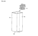
- FIG. 1 is a perspective view showing a silicon packaging bag 1 of the present embodiment.
- silicone is comprised from transparent films, such as synthetic resins, such as polyethylene, for example, and as shown in FIG. 1, four side surface parts 2,2,3,3 and the bottom face part 4 are comprised.
- the packaging bag 1 can be folded small into a pair of opposing side surface portions 3 and 3 among the four side surface portions 2, 2, 3 and 3. For this purpose, a fold line that can be bent inward is provided at the center in the width direction. When not in use, the silicon packaging bag 1 is folded along this crease and is compact, and is formed into a bag shape by being unfolded during use.
- the bottom surface portion 4 is in the end of the other pair of side surface portions 2 and 2 with the pair of side surface portions 3 and 3 folded along the crease at one end of the film.
- the side seals are overlapped and sealed with a sealing device to form the bottom seal 7.
- bulk polycrystalline silicon W that is a raw material of single crystal silicon is mainly targeted for packaging.
- the massive polycrystalline silicon W is produced in a rod shape by a vapor phase method called a Siemens method, and then manufactured by being processed (for example, cut) or crushed so as to be easily used as a raw material.
- FIG. 2A the inside of the inner bag 1a is filled with a predetermined amount of massive polycrystalline silicon W as the inner bag 1a (packaging bag).
- FIG. 2B in the opening at the upper end of the inner bag 1a, the inner side surfaces of the pair of side surface portions 2a, 2a that are not creased are overlapped to form an overlapping portion 8a.
- the inner bag 1a is sealed by heat-sealing the upper end of the overlapping portion 8a along the horizontal direction (the width direction of the inner bag 1a).
- FIG. 2C the strip
- FIG. 3 is a diagram showing a welding seal planned portion H11, a planned sandwiching portion H12, and a surplus length portion H13 in the sealing region H1 of the inner bag 1a filled with the bulk polycrystalline silicon W
- FIG. 4 is a planned welding seal. It is a figure which shows the example by which the stick 30 is arrange
- the inner bag 1a filled with the bulk polycrystalline silicon W includes a filling portion J1 filled with the bulk polycrystalline silicon W and a sealing region H1 (overlapping portion 8a) located on the opening side of the inner bag 1a.
- region H1 is clamped by each of the clamping stick
- the planned portion to be sandwiched and welded by the seal rod 30 is referred to as a welding seal planned portion H11
- the planned portion to be sandwiched by the sandwiching rod 20 is referred to as a planned sandwich portion H12.
- a welding seal planned portion H ⁇ b> 11 is disposed in the vicinity of the opening of the inner bag 1 a along the width direction of the inner bag 1 a, and the filling portion J ⁇ b> 1 from the welding seal planned portion H ⁇ b> 1.
- a planned holding portion H12 is disposed along the width direction of the inner bag 1a, and an extra length portion is provided between the welding seal scheduled portion H1 (the welded seal portion S1 after being welded by the seal rod 30) and the filling portion J1. H13 is formed. Then, the sandwiching rod 20 sandwiches the planned sandwiching portion H12, and the seal rod 30 sandwiches the planned welding seal portion H12.
- the seal rod 30 and the sandwiching rod 20 are arranged parallel to each other along the width direction of the inner bag 1a.
- the width direction of the inner bag 1a is not necessarily limited. It does not need to be arranged in parallel with the case, and includes a case of being arranged obliquely with respect to the width direction of the inner bag 1a. Further, the seal rod 30 and the sandwiching rod 20 may not be arranged parallel to each other.
- the width and length of the seal rod 30 and the sandwiching rod 20 are also appropriately set according to the material, width dimension, and the like of the inner bag 1a.
- the welding seal planned portion H11 and the sandwiched planned portion H12 are arranged with a certain interval, but it is desirable that this interval is narrow. Since the gas component generated when the welding seal scheduled portion H11 is welded adheres to the inner surface of the inner bag 1a between the scheduled portions H11 and H12, the interval is reduced (the distance is shortened). The region to which the gas component is attached can be limited to a small size, and can be kept away from the bulk polycrystalline silicon W, and contamination of the filled bulk polycrystalline silicon W can be suppressed.
- the extra length part H13 provided between the sandwiching scheduled part H12 and the filling part J1 is a part that is bent after the welding seal scheduled part H11 is welded.
- a region where the gas component generated between the welding seal part S1 and the sandwiching part H121 during welding adheres to the inner surface of the inner bag 1a is held in the bent part of the extra length H13. This prevents the region from coming into contact with the bulk polycrystalline silicon W.
- the welding device 40 is constituted by, for example, an impulse sealer or the like, and is heated and welded in a state in which the sandwiching rod 20 that sandwiches the sandwiching planned portion H12 and the welding seal planned portion H11 are sandwiched so that gas does not flow into the filling portion J1.
- one of the seal rods 30 is a fixed receiving portion, and the other is configured by a pressurizing portion that is disposed to face the receiving portion and moves toward the receiving portion.
- sticker scheduled part H11 is provided in one or both of a receiving part and a pressurization part.
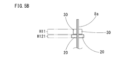
- Such welding (heat sealing) processing by the welding apparatus 40 is performed, for example, in the order of steps shown in FIG. In FIG. 5, a part of the overlapping portion 8a (the vicinity of the welding seal planned portion H11 and the sandwiched planned portion H12) is shown in an enlarged manner.
- the sandwiched portion H12 of the inner bag 1a filled with the bulk polycrystalline silicon W is sandwiched by being pressed from both sides with a sandwiched rod 20 that has been cooled in advance so that gas cannot flow. .
- the sandwiching rod 20 since the sandwiching rod 20 has been cooled in advance, the temperature of the sandwiching portion (portion sandwiched by the sandwiching rod 20) H121 and its surroundings is lowered.
- the welding seal planned portion H11 is sandwiched by the seal rod 30 as shown in FIG. 5B.
- a large current instantaneously flows to a heater (not shown) attached to one of the seal rods 30 and the heater generates heat
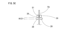
- the heat-conducting heat causes the welding seal scheduled portion H11 to be heated as shown in FIG. 5C. It welds and becomes welding seal part S1.
- the welding seal planned portion H11 is welded, a gas accompanying the welding is generated, but the clamping portion H121 on the lower side (opposite to the opening) of the welding seal planned portion H11 is held by the holding rod 20. Therefore, the gas generated from the welding seal part S1 on the side opposite to the opening side does not flow into the filling part J1 (on the side opposite to the opening part).
- the sealing is performed by the clamping rod 20 cooled in advance.
- the sealing may be performed in a state in which cold air is blown to the clamping rod 20 and its surroundings.
- the sealing rod 30 is clamped to the welding seal planned portion H11 while performing cold sealing while blowing cold air around the clamping rod 20 or the periphery of the clamping rod 20 (between the clamping portion H121 and the welding planned portion H12).
- the same effect as in the case of performing the welding seal using the pre-cooled holding rod 20 is obtained, and the gas generated when welding the welding seal scheduled portion H11 is cooled by the cold air.
- the temperature between the part S1 and the sandwiching part H121 is also difficult to increase, the amount of gas generated is suppressed, and contamination to the bulk polycrystalline silicon W is suppressed.
- the seal rod 30 is removed from the weld seal portion S1, as shown in FIG. 5D.
- the temperature of welding seal part S1 falls to normal temperature (for example, 25 degreeC)
- rod 20 is removed from the clamping part H121, and it will be in the state shown in FIG.
- the filling portion J1 is prevented from being contaminated by the gas component even if the clamping rod 20 is removed.
- the extra length H13 on the filling portion J1 side is bent a plurality of times from the portion held by the holding rod 20, so that the portion between the portion held by the holding rod 20 and the welding seal portion S1 is bent. Fold it so that it wraps around.
- the inner bag 1a is in a state in which the extra length H13 is folded and filled with the bulk polycrystalline silicon W. Since the surplus length portion H13 is bent, the surplus length portion H13 that is bent is interposed between the region where the gas component adheres on the inner surface of the inner bag 1a and the filling portion J1, and the bulk polycrystal in the filling portion J1. The contact of the gas component with the silicon W is further suppressed.
- the inner side bag packaging body 10a (1st packaging body) with which the inside bag 1a was filled and sealed with the lump polycrystal silicon W is accommodated in the outer side bag 1b (2nd packaging bag).
- the outer bag 1b has the same shape as the packaging bag 1 described above, like the inner bag 1a, but its outer diameter is slightly larger than the outer diameter of the inner bag 1a.
- the outer bag 1b that accommodates the inner bag packaging body 10a in this way is similar to the inner bag 1a in that the inner side surfaces of the pair of side surface portions 2b, 2b that are not creased at the opening at the upper end of the outer bag 1b are connected.
- the overlapping portion 8b is formed by overlapping, and the vicinity of the upper end portion of the overlapping portion 8b is sealed by heat sealing in the same manner as the inner bag 1a, and the inner bag packaging body 10a is packaged.
- a portion of the outer bag 1b that houses the inner bag package 10a is referred to as a housing portion J2.
- the procedure is the same as the packaging method for the inner bag 1a described above. Therefore, referring to FIGS. 2 to 5 as necessary, the common portion includes the inner bag 1a. It demonstrates using the same code
- the filling part J1 in FIGS. 2 to 5 is read as the accommodating part J2.
- the welding located on the opening side of the outer bag 1b with respect to the housing portion J2 containing the inner bag packaging body 10a.
- the sandwiched portion H12 located on the side of the housing portion J2 of the inner bag package 10a from the planned seal portion H11 is sandwiched by the sandwiching rod 20 so that no gas can flow, and the sandwiched portion H121 is sandwiched by the sandwiching rod 20
- a weld seal scheduled portion H11 is sandwiched between the seal rods 30 and welded, and after the temperature of the weld seal portion S1 has dropped to room temperature, the seal rod 30 and the sandwiching rod 20 are removed to perform heat sealing.
- a double-structured silicon package 10 containing the massive polycrystalline silicon W shown in FIG. 7 is formed.
- the part by the side of the accommodating part J2 is bend
- a band-like folded part (not shown) is formed, and the substantially rectangular parallelepiped package 10 is obtained.
- the outer bag 1b is sealed in a state of being sandwiched by the cooled sandwiching bar 20 in the same manner as the inner bag 1a, so that the gas generated when welding the welding seal scheduled portion H11 of the outer bag 1b is retained.
- the temperature around the sandwiching portion H121 also decreases, so that the temperature between the welded seal portion S1 and the sandwiching portion H121 is also unlikely to rise, and the amount of gas generated is also suppressed.
- the adhesion seal portion prevents the gas component generated during welding from adsorbing to the inner surface of the outer bag 1b.
- the acceleration can be promoted within a limited range between S1 and the sandwiching portion H121, and adhesion of the gas component to the outer surface of the inner bag package 10a can be suppressed.
- the holding rod 20 holds the holding portion H121 until the temperature of the welding seal portion S1 is lowered to the normal temperature, that is, after the temperature of the welding seal portion S1 is lowered to the normal temperature, the holding rod 20 is removed. It is possible to suppress the gas component generated during welding from flowing into the outer bag 1b.
- the portion on the housing portion J2 side is bent from the portion held by the holding rod 20 in the extra length portion H13 of the outer bag 1b, and welded to the portion held by the holding rod 20
- the surplus portion H13 so as to wrap between the seal portions S1
- the adhesion of the gas component to 10a is suppressed.
- such a package 10 is conveyed to a manufacturing plant or the like that manufactures single crystal silicon, and the packaged bulk polycrystalline silicon W is opened from the package 10 to become a raw material for manufacturing single crystal silicon.
- the gas component generated when the outer bag 1b is welded is the inner bag in the outer bag 1b. It suppresses flowing into the portion in which the packaging body 10a is accommodated, thereby suppressing the adhesion of gas components to the outer surface of the inner bag packaging body 10a, and contacts the inner bag packaging body 10a when opened on the use side. Can prevent contact contamination. Thereby, contamination in the production of single crystal silicon can also be suppressed.
- the housing portion J2 (in the inner bag 1a) is located in the outer bag 1b rather than the portion sandwiched by the sandwiching rod 20 so as to remove the portion sandwiched by the welding seal portion S1 and the sandwiching rod 20.
- the outer bag 1b and the inner bag 1a are cut at the position of the filling part J1 (hereinafter referred to simply as “accommodating part J2 (filling part J1)” or “filling part J1 (accommodating part J2)”)).
- a display indicating a cutting suitable position at a position closer to the housing portion J2 (filling portion J1) than the sandwiching portion 121 may be attached.
- the clamping rod H12 located on the filling portion J1 (accommodating portion J2) side of the planned welding seal portion H11 is prevented from flowing gas.
- the welding seal scheduled portion H ⁇ b> 11 is welded by the seal rod 30.
- the gas generated when the packaging bag 1 is welded is generated on both sides of the welding seal portion S1, but the sandwiching portion H121 located on the filling portion J1 (accommodating portion J2) side is sandwiched by the sandwiching rod 20.
- the gas generated from the welding seal part S1 on the side opposite to the opening does not flow into the filling part J1 (accommodating part J2) (on the side opposite to the opening).
- the holding rod 20 is removed after the temperature of the welding seal portion S1 reaches room temperature, the amount of impurities flowing into the filling portion J1 (housing portion J2) of the bulk polycrystalline silicon W can be suppressed, and the bulk polycrystalline silicon due to the above gas. Contamination due to W surface carbon impurities can be suppressed.
- the temperature of the clamping part H121 falls by clamping the clamping planned part H12 with the cooled clamping rod 20, the heat generated when the welding seal scheduled part H11 is welded spreads to the clamping part H121. It is suppressed.
- the gas generated when welding the welding seal scheduled portion H11 is cooled by the sandwiching rod 20 the temperature around the sandwiching portion H121 also decreases, so the portion between the welding seal portion S1 and the sandwiching portion H121. However, the temperature is difficult to rise and the amount of gas generated is also suppressed.
- the adhesion seal portion prevents adsorption of the gas component generated during welding to the inner surface of the inner bag 1a. It can be promoted within a limited range between S1 and the sandwiching portion H121, and adhesion of the gas component to the bulk polycrystalline silicon W can be suppressed.
- the region to which the gas component generated at the time of welding on the inner surface of the inner bag 1a adheres is a massive Contact with the crystalline silicon W can be suppressed, and surface contamination of the bulk polycrystalline silicon W due to carbon impurities can be reliably suppressed.
- the bulk polycrystalline silicon is double-packaged by the two packaging bags 1 (the inner bag 1a and the outer bag 1b), for example, even if the inner bag 1a is torn when being transported, the outer bag Lumped polycrystalline silicon W can be stored between 1b and inner bag 1a, and these can be prevented from being exposed to the outside atmosphere and being contaminated.
- the gas component accompanying the welding seal adheres to the inner surface of the inner bag 1a (or outer bag 1b) closer to the filling portion J1 (accommodating portion J2) than the welding seal portion S1. Therefore, when the inner bag 1a (or the outer bag 1b) is opened, a certain length is separated from the welding seal portion S1 to the filling portion J1 (accommodating portion J2) (at least to the portion held by the holding rod 20). After cutting off the extra length H13 (including removal), the bulk polycrystalline silicon W (or the inner bag package 10a) is taken out from the inner bag 1a (or the outer bag 1b), so that the gas components adhere at the time of removal. Can be avoided.
- the seal rod 30 is disposed so as to cover the entire region in the width direction of the welding seal planned portion H11, and the weld seal planned portion H11 is welded at one time.
- the welding seal portion S1 is formed, but not limited to this, a part of the welding seal scheduled portion H11 is welded and an unwelded portion is formed in a part of the packaging bag 1 in the width direction, and is generated at the time of welding. After discharging the gas to be welded from the unwelded portion, the weld seal portion S1 may be formed by welding the remainder (unwelded portion) of the weld seal scheduled portion H11.
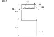
- FIG. 8 is a diagram showing an example in which a part of the welding seal scheduled portion H11 of the silicon packaging bag 1a filled with the bulk polycrystalline silicon W according to the modification of the embodiment is heat-sealed.
- the inner bag 1a will be described as an example, but the same applies to the outer bag 1b in the case of double packaging.
- the planned welding seal portion H11 when the planned welding seal portion H11 is welded by the seal rod 30 with the planned sandwiching portion H12 held by the clamping rod 20, gas can be circulated with the welded portion S21 welded by the seal rod 30.
- the unsealed portion is continuously formed along the sandwiched portion H121, and the gas between the welded portion S21 and the planned sandwiched portion H12 is opened from the small opening portion 81 constituted by the unwelded portion to the opening portion of the inner bag 1a. After discharging to the side, the unwelded portion (small opening portion 81) of the welding seal scheduled portion H11 is welded.
- the gas from the small opening 81 is discharged out of the packaging bag 1a by being sucked from the outside of the inner bag 1a or pushed out by pressing between the welding portion S21 and the sandwiching portion H121.
- the said gas is a gas produced when welding a part of welding seal scheduled part H11.
- the welded portion S21 and the unwelded portion welded by the seal rod 30 are continuously formed along the sandwiching portion H121. Therefore, when a part of the welded seal scheduled portion H11 is welded, the welded portion S21 is formed. And the gas generated between the holding portion H121 can be discharged to the outside from the small opening 81 constituted by the unwelded portion.
- the width of the unwelded portion is smaller than the entire width of the welded portion S1
- the gas generated when the unwelded portion is welded does not form the unwelded portion and the entire width of the packaging bag 1 Since the amount thereof is smaller than that of the welding method of the above-described embodiment, the contamination by the surface carbon impurities of the massive polycrystalline silicon W can be further suppressed.
- the small opening 81 constituted by the unwelded portion is provided at the right end portion of FIG. 8.
- the present invention is not limited to this, and the welding seal portion may be provided on the left side of FIG. 8. Any one of them may be sufficient.
- a plurality of small openings 81 may be provided. In these cases as well, it is desirable to remove the clamping rod after the temperature of the welded seal portion has dropped.
- each method of the above-described modification can also be applied when the outer bag 1b that houses the inner bag package 10a is welded. In this case, it is possible to further suppress contamination of the outer surface of the inner bag package 10a due to the gas generated when the outer bag 1b is welded.
- the sandwiching rod 20 is cooled in advance, but is not limited thereto. For example, it is good also as cooling after clamping the clamping planned part H12.
- the temperature of the planned welding seal portion is likely to be lower than when the clamping rod 20 is not cooled.
- the width dimension of the welding seal scheduled portion H11 may be set to such an extent that the welding strength of the portion S1 does not decrease.
- the welding device 40 may separately provide a cooling rod between the sandwiching rod 20 and the seal rod 30, and the cooling rod may cool between the planned sandwiching portion H12 and the planned welding seal portion H11.
- the sandwiching rod 20 may not be cooled.
- the sandwiching rod 20 may be removed after the temperature of the welding seal portion S1 is lowered to room temperature.
- the welding apparatus 40 is composed of an impulse sealer.
- the method of the present invention is possible even when welding is performed using a hot plate sealer, hand sealer, high frequency sealer, ultrasonic sealer, or the like.
- the welding apparatus 40 is configured to include the seal rod 30 and the sandwiching rod 20, but the welding apparatus may be configured so that the sealing rod and the sandwiching bar are separate apparatus configurations and sealed. Good.
- the silicon packaging bag 1 can be a low-density polyethylene bag, and other bags such as bags made of other materials such as polypropylene can also be used. Conditions such as the welding temperature in the welding apparatus are appropriately set according to the material of the packaging bag, the welding width, the welding strength, and the like.
- a polyethylene bag having a thickness of about 0.3 mm and a width of about 140 mm was used as a packaging bag, filled with massive polycrystalline silicon, and welded and sealed using an impulse sealer (MTB-25 manufactured by Enomoto Kogyo Co., Ltd.).
- Bulk polycrystalline silicon having a maximum side length of 20 mm to 50 mm was placed on a glass petri dish and stored in a packaging bag.
- the cleaned petri dish is placed in an electric furnace, and at about 500 ° C. for about 120 minutes. Heat-treated. Thereby, when impurities derived from organic substances adhere to the surface of the massive polycrystalline silicon, most of them are volatilized and removed.
- the pre-treated bulk polycrystalline silicon was housed in the packaging bag together with the petri dish so as not to contact the inner surface of the packaging bag.
- the reason why the petri dish is accommodated is to eliminate adhesion of carbon impurities from the packaging bag from the contact portion with the packaging bag.
- the sealing rod of the impulse sealer was set to a temperature of about 160 ° C. with the planned sandwiching portion of the packaging bag held by the sandwiching rod, and the opening was welded.
- a plastic plate material having a flat surface with a width of about 10 mm was used as the holding bar, and the packaging bag was held on the flat surface so that no gas could flow.
- the distance between the portion sandwiched by the sandwiching rod and the welded portion was 20 mm.
- Example 3 the position of the welding planned portion is shifted with respect to the position of the seal rod, and the length of 3 mm at the end of the width of the packaging bag is not welded.
- the remaining portion was welded, and then the portion between the welded portion and the sandwiching portion was pressed to discharge the gas between them from the small opening of the unwelded portion, and then the unwelded portion was welded. Thereafter, in the same manner as in Example 1 and Example 2, one in which the extra length was folded (Example 3) and one that was not folded (Example 4) was produced.
- Example 3 and Example 4 the above-described welding was performed while the planned sandwiching portion was sandwiched from the stage of forming the unwelded portion to the welding of the unwelded portion.
- the other handling procedures and methods of the sandwiching rod and the welding seal rod at the time of welding seal were the same as those in Example 1 and Example 2.
- the sandwiching rod for sandwiching the packaging bag was stored in an atmosphere at about 5 ° C. before use, and the packaging bag was sandwiched and welded with the sandwiching rod.
- the temperature of the sandwiched portion and its surroundings at the time of welding was 5 ° C. to 10 ° C. Thereafter, in the same manner as in Example 1 and Example 2, one in which the extra length was folded (Example 5) and one that was not folded (Example 6) were produced.
- Example 5 and Example 6 the handling procedure and method of the sandwiching rod and the welding seal rod at the time of welding and sealing were the same as those in the above examples.
- Comparative Example 1 a packaging bag that was not clamped by a clamping rod during welding (Comparative Example 1) was prepared, and as a reference example, the opening was not welded and closed with a clip so that gas could not be circulated ( Reference Example 1) was also produced.
- the heating at the time of welding sealing was 2.1 seconds
- the cooling after heating (temperature drop) was 5 seconds
- the sealing rod was removed from the welding portion.
- the package containing the bulk polycrystalline silicon as described above was stored at room temperature (about 25 ° C.) for about 5 hours.
- the above packaging and storage were performed in a clean room (Fed-Std209E class 1000 of the US federal standard).
- the packaging bodies of the examples and comparative examples thus obtained were opened, the packed polycrystalline silicon was taken out, and the impurity concentration on the surface thereof was measured using a thermal desorption gas chromatograph mass spectrometer (TD-GC). / MS). The results are shown in Table 1.
- the main components of the measured carbon impurities were 1-Butanol, Toluene, 1,3,5,7-Cyclooctatetrain, 1-Hexanol, 2-ethyl-, Alkane, and other components (other components were oxidized by Alkane) It seems).
- the bulk polycrystalline silicon packaged by the packaging method of the example is less contaminated with carbon impurities on the surface than the comparative example 1 in which no sandwiching bar is used, and the carbon impurity concentration is 4.3 ppbw.
- the level was the same as that of Reference Example 1 which was not welded.
- produces at the time of welding by forming an unwelded part was also confirmed. It has also been confirmed that the impurity concentration is reduced by suppressing the temperature around the welded portion by the cooled sandwiching rod.
- the carbon impurity concentration on the surface of the bulk polycrystalline silicon was reduced in the example 1 in which the surplus part was folded after welding compared to the example 2 in which the surplus part was not folded.
- the surface carbon impurities were reduced as compared to Examples 4 and 6 in which the surplus portion was not folded.
- the packaging method of the present invention shows a reduction in carbon impurities (organic impurities) that are considered to be components of the packaging bag generated at the time of welding and sealing the opening.
- carbon impurities organic impurities
- Lump-like polycrystalline silicon used as a melting raw material when producing single crystal silicon or the like can be packaged with reduced surface contamination by organic impurities, particularly carbon impurities.
- Packaging bag for silicon (packaging bag) 1a Inner bag (packaging bag) 1b Outer bag (packaging bag) 2 2a 2b 3 3a 3b Side face part 4 Bottom face part 7 Bottom seal part 8a 8b Overlapping part 9a Folding part 10 Packaging body 10a Inner bag packaging body 20 Holding bar 30 Sealing bar 40 Welding device 81 Small opening (unwelded part) H1 sealing region H11 planned weld seal portion H12 planned sandwich portion H121 sandwiched portion H13 extra length portion J1 filling portion J2 housing portion S1 weld seal portion S21 weld portion W massive polycrystalline silicon
Abstract
Description
が可能な未溶着部とを前記包装袋の開口部の幅方向に連続するように形成し、前記溶着部と前記挟持棒により挟持されている部分との間の気体を前記未溶着部により構成される小開口部から前記包装袋外に排出した後、前記未溶着部を溶着するとよい。 As a preferred aspect of the method for packaging polycrystalline silicon, when the weld seal planned portion is welded by the seal rod, the weld portion welded by the seal rod and the unwelded portion capable of gas circulation are packaged. Formed continuously in the width direction of the opening of the bag, and the gas between the welded portion and the portion sandwiched by the sandwiching rod from the small opening configured by the unwelded portion outside the packaging bag After discharging, the unwelded portion may be welded.
本実施形態では、シリコン用包装袋1は、例えばポリエチレンなどの合成樹脂等の透明フィルムから構成され、図1に示すように、4つの側面部2,2,3,3と底面部4とを備えた横断面略長方形状の形状を有しており、4つの側面部2,2,3,3のうち対向する一対の側面部3,3には、該包装袋1を小さく折り畳むことができるようにするため、幅方向の中央位置に内側に向かって屈曲可能な折り目が設けられている。未使用時においては、シリコン用包装袋1はこの折り目に沿って畳まれてコンパクトなものであり、使用時に広げることによって袋状になる。 FIG. 1 is a perspective view showing a
In this embodiment, the
次に、塊状多結晶シリコンWの包装方法の具体的手順について説明する。上記の構成の包装袋1を内側袋1a(包装袋)として、図2Aに示すように、まず該内側袋1aの内部に塊状多結晶シリコンWを所定量充填する。次に、図2Bに示すように、内側袋1aの上端の開口部において、折り目のついていない一対の側面部2a,2aの内側面同士を重ね合わせて重ね合わせ部8aを形成する。その後、重ね合わせ部8aの上端部を水平方向(内側袋1aの幅方向)に沿って熱シールすることで、内側袋1aは封止される。そして、図2Cに示すように、帯状の折り畳み部9aを形成する。これにより、塊状多結晶シリコンWの内側袋1aへの充填手順が終了する。 [Packaging method for bulk polycrystalline silicon]
Next, a specific procedure of the packaging method for the bulk polycrystalline silicon W will be described. As shown in FIG. 2A, the inside of the
なお、外側袋1bも内側袋1aと同様に、前述した包装袋1と同一形状とされているが、その外径寸法は内側袋1aの外径寸法よりも僅かに大きなものとされている。
内側袋包装体10aを外側袋1bに収容する際には、断面形状である略正方形の辺を揃えるようにして収容する。 And the inner side
The
When the inner

1a 内側袋(包装袋)
1b 外側袋(包装袋)
2 2a 2b 3 3a 3b 側面部
4 底面部
7 底シール部
8a 8b 重ね合わせ部
9a 折り畳み部
10 包装体
10a 内側袋包装体
20 挟持棒
30 シール棒
40 溶着装置
81 小開口部(未溶着部)
H1 封止領域
H11 溶着シール予定部
H12 挟持予定部
H121 挟持部
H13 余長部
J1 充填部
J2 収容部
S1 溶着シール部
S21 溶着部
W 塊状多結晶シリコン 1 Packaging bag for silicon (packaging bag)
1a Inner bag (packaging bag)
1b Outer bag (packaging bag)
2
H1 sealing region H11 planned weld seal portion H12 planned sandwich portion H121 sandwiched portion H13 extra length portion J1 filling portion J2 housing portion S1 weld seal portion S21 weld portion W massive polycrystalline silicon
Claims (8)
- 包装袋に多結晶シリコンを充填した後、前記多結晶シリコンが充填されてなる充填部よりも前記包装袋の開口部側でありかつ前記包装袋を溶着してシールするための溶着シール予定部より前記充填部側の部位を、前記充填部に気体が流れ込まない様に挟持棒で挟持し、該挟持棒により挟持した状態で前記溶着シール予定部をシール棒により挟んで溶着し、溶着後に前記挟持棒を取り外すことを特徴とする多結晶シリコンの包装方法。 After filling the packaging bag with polycrystalline silicon, from the welding seal planned portion for welding and sealing the packaging bag that is closer to the opening side of the packaging bag than the filling portion filled with the polycrystalline silicon The portion on the filling portion side is sandwiched by a sandwiching rod so that no gas flows into the filling portion, and the welding seal planned portion is sandwiched by a sealing rod in a state of being sandwiched by the sandwiching rod, and the sandwiched portion is held after the welding. A method for packaging polycrystalline silicon, comprising removing a rod.
- 前記溶着シール予定部を前記シール棒により溶着する際に、前記シール棒により溶着された溶着部と気体の流通が可能な未溶着部とを前記包装袋の開口部の幅方向に連続するように形成し、前記溶着部と前記挟持棒により挟持されている部分との間の気体を前記未溶着部により構成される小開口部から前記包装袋外に排出した後、前記未溶着部を溶着することを特徴とする請求項1に記載の多結晶シリコンの包装方法。 When welding the weld seal planned portion with the seal rod, the weld portion welded with the seal rod and the unwelded portion where gas can be circulated are continued in the width direction of the opening of the packaging bag. Forming and discharging the gas between the welded portion and the portion clamped by the clamping rod out of the packaging bag from the small opening formed by the unwelded portion, and then welding the unwelded portion The method for packaging polycrystalline silicon according to claim 1.
- 前記挟持棒またはその周辺が冷却された状態で前記包装袋を挟持することを特徴とする請求項1又は2に記載の多結晶シリコンの包装方法。 3. The method for packaging polycrystalline silicon according to claim 1, wherein the packaging bag is sandwiched in a state where the sandwiching rod or its periphery is cooled.
- 前記溶着シール予定部が前記シール棒により溶着された後、前記挟持棒により挟持されていた部位と前記充填部との間で前記包装袋を折り曲げることを特徴とする請求項1から3のいずれか一項に記載の多結晶シリコンの包装方法。 4. The packaging bag according to claim 1, wherein the packaging bag is folded between a portion sandwiched by the sandwiching rod and the filling portion after the welding seal planned portion is welded by the seal rod. The method for packaging polycrystalline silicon according to one item.
- 前記挟持棒は、前記シール棒を取り外した後に取り外されることを特徴とする請求項1から4のいずれか一項に記載の多結晶シリコンの包装方法。 5. The polycrystalline silicon packaging method according to any one of claims 1 to 4, wherein the sandwiching rod is removed after the sealing rod is removed.
- 請求項1から5のいずれか一項に記載の多結晶シリコンの包装方法により前記多結晶シリコンが前記包装袋に包装された第1包装体を、前記包装袋とは異なる第2包装袋に収容した後、
前記第1包装体を収容してなる収容部よりも前記第2包装袋の開口部側でありかつ前記第2包装袋を溶着してシールするための溶着シール予定部より前記収容部側の部位を、前記収容部に気体が流れ込まない様に挟持棒で挟持し、該挟持棒により挟持した状態で前記溶着シール予定部をシール棒により挟んで溶着し、溶着した後に前記挟持棒を取り外すことを特徴とする多結晶シリコンの二重包装方法。 The first packaging body in which the polycrystalline silicon is packaged in the packaging bag by the polycrystalline silicon packaging method according to any one of claims 1 to 5 is accommodated in a second packaging bag different from the packaging bag. After
A portion closer to the housing portion than a welding seal planned portion for welding and sealing the second packaging bag, closer to the opening portion of the second packaging bag than the housing portion containing the first packaging body. Is held by a sandwiching rod so that gas does not flow into the housing portion, and the welding seal planned portion is sandwiched by a seal rod in a state of being sandwiched by the sandwiching rod, and after the welding, the sandwiching rod is removed. Characteristic double packing method for polycrystalline silicon. - 前記挟持棒は、前記シール棒を取り外した後に取り外されることを特徴とする請求項6に記載の多結晶シリコンの二重包装方法。 The double-wrapping method for polycrystalline silicon according to claim 6, wherein the sandwiching rod is removed after the sealing rod is removed.
- 多結晶シリコンを加工または破砕して塊状多結晶シリコンを形成し、該塊状多結晶シリコンを請求項1から請求項5のいずれか一項に記載の多結晶シリコンの包装方法、又は請求項6又は7に記載の多結晶シリコンの二重包装方法により包装し、包装された前記塊状多結晶シリコンを包装袋から取り出して、単結晶シリコンを製造する原料とすることを特徴とする単結晶シリコン用原料製造方法。 The polycrystalline silicon is processed or crushed to form bulk polycrystalline silicon, and the polycrystalline silicon packaging method according to any one of claims 1 to 5, or claim 6 or A raw material for single crystal silicon, characterized in that it is packaged by the double packaging method of polycrystalline silicon according to claim 7, and the packed polycrystalline silicon is taken out from a packaging bag and used as a raw material for producing single crystal silicon Production method.
Priority Applications (5)
| Application Number | Priority Date | Filing Date | Title |
|---|---|---|---|
| US17/048,242 US20210070484A1 (en) | 2018-04-18 | 2019-04-18 | Packaging method for polycrystalline silicon, double-packaging method for polycrystalline silicon, and producing method of raw material for monocrystalline silicon |
| EP19789357.1A EP3782917B1 (en) | 2018-04-18 | 2019-04-18 | Packaging method for polycrystalline silicon, double-packaging method for polycrystalline silicon, and production method for raw material for monocrystalline silicon |
| JP2020514442A JP7131608B2 (en) | 2018-04-18 | 2019-04-18 | Polycrystalline silicon packaging method, polycrystalline silicon double packaging method, and single crystal silicon raw material manufacturing method |
| CN201980026289.5A CN111989267B (en) | 2018-04-18 | 2019-04-18 | Method for packaging polycrystalline silicon, method for double-packaging polycrystalline silicon, and method for producing raw material for single-crystal silicon |
| KR1020207031636A KR102656754B1 (en) | 2018-04-18 | 2019-04-18 | Packaging method for polycrystalline silicon, double packaging method for polycrystalline silicon, and raw material manufacturing method for single crystal silicon |
Applications Claiming Priority (2)
| Application Number | Priority Date | Filing Date | Title |
|---|---|---|---|
| JP2018079562 | 2018-04-18 | ||
| JP2018-079562 | 2018-04-18 |
Publications (1)
| Publication Number | Publication Date |
|---|---|
| WO2019203316A1 true WO2019203316A1 (en) | 2019-10-24 |
Family
ID=68239548
Family Applications (1)
| Application Number | Title | Priority Date | Filing Date |
|---|---|---|---|
| PCT/JP2019/016660 WO2019203316A1 (en) | 2018-04-18 | 2019-04-18 | Packaging method for polycrystalline silicon, double-packaging method for polycrystalline silicon, and production method for raw material for monocrystalline silicon |
Country Status (6)
| Country | Link |
|---|---|
| US (1) | US20210070484A1 (en) |
| EP (1) | EP3782917B1 (en) |
| JP (1) | JP7131608B2 (en) |
| KR (1) | KR102656754B1 (en) |
| CN (1) | CN111989267B (en) |
| WO (1) | WO2019203316A1 (en) |
Cited By (2)
| Publication number | Priority date | Publication date | Assignee | Title |
|---|---|---|---|---|
| JP7148762B1 (en) * | 2021-04-28 | 2022-10-05 | 株式会社トクヤマ | SEALING APPARATUS, MANUFACTURING APPARATUS FOR POLYCRYSTALLINE SILICON FILLING, AND METHOD FOR MANUFACTURING POLYCRYSTALLINE SILICON FILLING |
| WO2022230497A1 (en) * | 2021-04-28 | 2022-11-03 | 株式会社トクヤマ | Sealing device, device for producing polycrystalline silicon filler, and method for producing polycrystalline silicon filler |
Families Citing this family (1)
| Publication number | Priority date | Publication date | Assignee | Title |
|---|---|---|---|---|
| CN115610727A (en) * | 2022-11-10 | 2023-01-17 | 内蒙古大全新能源有限公司 | Packaging method for irregular polycrystalline silicon lump material |
Citations (9)
| Publication number | Priority date | Publication date | Assignee | Title |
|---|---|---|---|---|
| JPS5161392A (en) | 1974-11-22 | 1976-05-27 | Yokohama Jidoki Kk | Fukurozumetaino kanzendatsukishiiruhoho oyobi sochi |
| JPH01124528A (en) * | 1987-10-29 | 1989-05-17 | Nomura Sangyo Kk | Sealing method for opening of bag |
| JPH06227519A (en) * | 1993-02-03 | 1994-08-16 | Ishida Co Ltd | Lateral seal mechanism in bag-making packaging machine |
| JP2010036981A (en) * | 2007-08-27 | 2010-02-18 | Mitsubishi Materials Corp | Packaging method and packaging body of silicon |
| JP2013166557A (en) * | 2012-02-14 | 2013-08-29 | Toyo Jidoki Co Ltd | Bag degassing and sealing method and apparatus |
| JP2014108829A (en) | 2012-12-04 | 2014-06-12 | Wacker Chemie Ag | Packing of polysilicon |
| JP2014122153A (en) * | 2012-12-14 | 2014-07-03 | Wacker Chemie Ag | Packaging of polycrystalline silicon |
| JP2017057119A (en) | 2015-09-17 | 2017-03-23 | 信越化学工業株式会社 | Housing jig of polycrystalline silicon, examination method of housing jig of polycrystalline silicon and manufacturing method of polycrystalline silicon |
| JP2018079562A (en) | 2006-04-10 | 2018-05-24 | フランツ・ハイマー・マシーネンバウ・カーゲー | Means for preventing tool from pulling out from tool holder having tool holding fixture |
Family Cites Families (12)
| Publication number | Priority date | Publication date | Assignee | Title |
|---|---|---|---|---|
| DE2102493A1 (en) * | 1971-01-20 | 1972-08-03 | W.R. Grace & Co., New Yorfc, N. Y. (V.StA.) | Vacuum packaging - in sealed thin film envelope with mouth supported by clamp allowing air escape |
| JPS5437418Y2 (en) * | 1975-02-24 | 1979-11-09 | ||
| US5311111A (en) | 1991-05-29 | 1994-05-10 | Orbotech Ltd. | Method of calibrating a step motor |
| JP3158021B2 (en) * | 1995-10-13 | 2001-04-23 | 株式会社クボタ | Packaging equipment |
| DE10023308A1 (en) * | 2000-05-15 | 2001-12-06 | Werner Kallweit | Vacuum packing machine has welding bar which can move up and down in base and rubber strip on hinged lid positioned over bar when it is closed, support blocks being mounted in front of or behind bar whose tops are level with edge of base |
| US6862867B2 (en) * | 2003-01-16 | 2005-03-08 | Pack-Tech, L.L.C. | Bag sealing system and method |
| US20090038273A1 (en) * | 2007-08-09 | 2009-02-12 | Rennco Llc | Sealing System for a Packaging Apparatus |
| US20090264363A1 (en) * | 2008-03-26 | 2009-10-22 | Ward Loren S | Leucine-Rich Peptide Compositions and Methods for Isolation |
| DE102008019625A1 (en) * | 2008-04-18 | 2009-10-29 | Multivac Sepp Haggenmüller Gmbh & Co. Kg | Method and device for packing a bulk material in bags |
| JP5779291B1 (en) * | 2014-08-22 | 2015-09-16 | 一夫 菱沼 | Composite heat seal structure adaptable to overlapping step |
| US20170081062A1 (en) * | 2015-09-21 | 2017-03-23 | Rethceif Enterprises, Llc | Apparatus for Pulling Vertically Positioned Horizontally Traversing Plastic Film Bag Walls and Heat Fusing the Walls and Closing the Bag |
| EP3630624B1 (en) * | 2017-06-01 | 2024-01-24 | Automated Packaging Systems, LLC. | Bagger safety system |
-
2019
- 2019-04-18 CN CN201980026289.5A patent/CN111989267B/en active Active
- 2019-04-18 WO PCT/JP2019/016660 patent/WO2019203316A1/en unknown
- 2019-04-18 KR KR1020207031636A patent/KR102656754B1/en active IP Right Grant
- 2019-04-18 EP EP19789357.1A patent/EP3782917B1/en active Active
- 2019-04-18 US US17/048,242 patent/US20210070484A1/en active Pending
- 2019-04-18 JP JP2020514442A patent/JP7131608B2/en active Active
Patent Citations (9)
| Publication number | Priority date | Publication date | Assignee | Title |
|---|---|---|---|---|
| JPS5161392A (en) | 1974-11-22 | 1976-05-27 | Yokohama Jidoki Kk | Fukurozumetaino kanzendatsukishiiruhoho oyobi sochi |
| JPH01124528A (en) * | 1987-10-29 | 1989-05-17 | Nomura Sangyo Kk | Sealing method for opening of bag |
| JPH06227519A (en) * | 1993-02-03 | 1994-08-16 | Ishida Co Ltd | Lateral seal mechanism in bag-making packaging machine |
| JP2018079562A (en) | 2006-04-10 | 2018-05-24 | フランツ・ハイマー・マシーネンバウ・カーゲー | Means for preventing tool from pulling out from tool holder having tool holding fixture |
| JP2010036981A (en) * | 2007-08-27 | 2010-02-18 | Mitsubishi Materials Corp | Packaging method and packaging body of silicon |
| JP2013166557A (en) * | 2012-02-14 | 2013-08-29 | Toyo Jidoki Co Ltd | Bag degassing and sealing method and apparatus |
| JP2014108829A (en) | 2012-12-04 | 2014-06-12 | Wacker Chemie Ag | Packing of polysilicon |
| JP2014122153A (en) * | 2012-12-14 | 2014-07-03 | Wacker Chemie Ag | Packaging of polycrystalline silicon |
| JP2017057119A (en) | 2015-09-17 | 2017-03-23 | 信越化学工業株式会社 | Housing jig of polycrystalline silicon, examination method of housing jig of polycrystalline silicon and manufacturing method of polycrystalline silicon |
Non-Patent Citations (2)
| Title |
|---|
| "Organic contaminant/ out-gas generation mechanism and trouble countermeasure case collection", 31 January 2008, TECHNICAL INFORMATION INSTITUTE CO., LTD |
| See also references of EP3782917A4 |
Cited By (4)
| Publication number | Priority date | Publication date | Assignee | Title |
|---|---|---|---|---|
| JP7148762B1 (en) * | 2021-04-28 | 2022-10-05 | 株式会社トクヤマ | SEALING APPARATUS, MANUFACTURING APPARATUS FOR POLYCRYSTALLINE SILICON FILLING, AND METHOD FOR MANUFACTURING POLYCRYSTALLINE SILICON FILLING |
| WO2022230497A1 (en) * | 2021-04-28 | 2022-11-03 | 株式会社トクヤマ | Sealing device, device for producing polycrystalline silicon filler, and method for producing polycrystalline silicon filler |
| KR20240004277A (en) | 2021-04-28 | 2024-01-11 | 가부시끼가이샤 도꾸야마 | Sealing device, manufacturing device for polycrystalline silicon filling, and manufacturing method for polycrystalline silicon filling |
| DE112022002337T5 (en) | 2021-04-28 | 2024-02-08 | Tokuyama Corporation | Closure device, device for producing a polycrystalline silicon filling and method for producing a polycrystalline silicon filling |
Also Published As
| Publication number | Publication date |
|---|---|
| JP7131608B2 (en) | 2022-09-06 |
| KR20200144105A (en) | 2020-12-28 |
| EP3782917B1 (en) | 2023-04-26 |
| CN111989267B (en) | 2022-06-03 |
| EP3782917A4 (en) | 2022-01-05 |
| EP3782917A1 (en) | 2021-02-24 |
| CN111989267A (en) | 2020-11-24 |
| JPWO2019203316A1 (en) | 2021-02-18 |
| KR102656754B1 (en) | 2024-04-11 |
| US20210070484A1 (en) | 2021-03-11 |
Similar Documents
| Publication | Publication Date | Title |
|---|---|---|
| WO2019203316A1 (en) | Packaging method for polycrystalline silicon, double-packaging method for polycrystalline silicon, and production method for raw material for monocrystalline silicon | |
| EP3130547B1 (en) | Compound heat seal structure capable of being fitted to level difference of stacked area and method of sealing a package | |
| JP5726984B2 (en) | Polycrystalline silicon packaging | |
| JP2009078537A (en) | Apparatus and method for filling continuous air filling type air enclosure with air | |
| CN109094861A (en) | A kind of packing method of chunk polysilicon | |
| JP2009202927A (en) | Double bag package and its manufacturing method | |
| JP7211154B2 (en) | Silicone packaging bag, silicone package, and silicone packaging method | |
| JP5303963B2 (en) | Package having release film and method for producing the same | |
| US20100247823A1 (en) | Molten Material and Package Combination and Method for Packaging Hot Melt Material | |
| JP3992487B2 (en) | Semiconductor wafer packaging method | |
| JP2002337820A (en) | Sealer and sealing method | |
| TWI498257B (en) | A method for hermetically closing an air-tight bag for pellicle | |
| KR102487247B1 (en) | Apparatus for packaging steel coil and method of packaging steel coil | |
| WO2015156085A1 (en) | Accommodating bag, container accommodating same accommodating bag, and composite film for forming same accommodating bag | |
| JP6644644B2 (en) | Vacuum packaging method and vacuum packaging machine | |
| JPH10194206A (en) | Method and device for bag packing | |
| JP3711037B2 (en) | Paper bag with film bag | |
| JPH0632330A (en) | Packaging film fusion/welding device | |
| JPH11170405A (en) | Manufacture of package with spout and device therefor | |
| JP2000153807A (en) | Device for winding up sealing-strip formed of weldable material on at least one article | |
| WO2022107852A1 (en) | Pouch for simple coffee extraction implement and simple coffee extraction implement bag | |
| WO2021241035A1 (en) | Content-filled film packing bag, vertical-type bag filling and packing device, method for manufacturing content-filled film packing bag | |
| US20240043153A1 (en) | Sealing device, device for producing polycrystalline silicon filler, and method for producing polycrystalline silicon filler | |
| JP7115674B2 (en) | Packaging method using film sheet | |
| JP2006335431A (en) | Bag sealing device and its method |
Legal Events
| Date | Code | Title | Description |
|---|---|---|---|
| 121 | Ep: the epo has been informed by wipo that ep was designated in this application |
Ref document number: 19789357 Country of ref document: EP Kind code of ref document: A1 |
|
| ENP | Entry into the national phase |
Ref document number: 2020514442 Country of ref document: JP Kind code of ref document: A |
|
| NENP | Non-entry into the national phase |
Ref country code: DE |
|
| ENP | Entry into the national phase |
Ref document number: 20207031636 Country of ref document: KR Kind code of ref document: A |
|
| ENP | Entry into the national phase |
Ref document number: 2019789357 Country of ref document: EP Effective date: 20201118 |