WO2019198409A1 - 植物用照明器具及び植物用照明装置 - Google Patents
植物用照明器具及び植物用照明装置 Download PDFInfo
- Publication number
- WO2019198409A1 WO2019198409A1 PCT/JP2019/010320 JP2019010320W WO2019198409A1 WO 2019198409 A1 WO2019198409 A1 WO 2019198409A1 JP 2019010320 W JP2019010320 W JP 2019010320W WO 2019198409 A1 WO2019198409 A1 WO 2019198409A1
- Authority
- WO
- WIPO (PCT)
- Prior art keywords
- reflecting member
- light
- plant
- light source
- inclined surface
- Prior art date
- Legal status (The legal status is an assumption and is not a legal conclusion. Google has not performed a legal analysis and makes no representation as to the accuracy of the status listed.)
- Ceased
Links
Images









Classifications
-
- A—HUMAN NECESSITIES
- A01—AGRICULTURE; FORESTRY; ANIMAL HUSBANDRY; HUNTING; TRAPPING; FISHING
- A01G—HORTICULTURE; CULTIVATION OF VEGETABLES, FLOWERS, RICE, FRUIT, VINES, HOPS OR SEAWEED; FORESTRY; WATERING
- A01G7/00—Botany in general
-
- Y—GENERAL TAGGING OF NEW TECHNOLOGICAL DEVELOPMENTS; GENERAL TAGGING OF CROSS-SECTIONAL TECHNOLOGIES SPANNING OVER SEVERAL SECTIONS OF THE IPC; TECHNICAL SUBJECTS COVERED BY FORMER USPC CROSS-REFERENCE ART COLLECTIONS [XRACs] AND DIGESTS
- Y02—TECHNOLOGIES OR APPLICATIONS FOR MITIGATION OR ADAPTATION AGAINST CLIMATE CHANGE
- Y02P—CLIMATE CHANGE MITIGATION TECHNOLOGIES IN THE PRODUCTION OR PROCESSING OF GOODS
- Y02P60/00—Technologies relating to agriculture, livestock or agroalimentary industries
- Y02P60/14—Measures for saving energy, e.g. in green houses
Definitions
- the present invention relates to a lighting technology for plants, and more particularly to a lighting device for plants and a lighting device for plants for removing pests that cause harm to plants.
- Patent Document 1 proposes to use UV-B light, which is a kind of ultraviolet light effective as a measure against plant pests. More specifically, in Patent Document 1, the light distribution can be easily controlled according to the growth of the plant, and when the plant grows and approaches the device, the lighting can prevent the plant from burning into the leaves. An apparatus is disclosed.
- Patent Document 2 similarly, in an apparatus for reducing plant diseases using UV-B light, the light emitted from the light source 2 is not directly applied to the plant P as shown in FIG. Thus, it has been proposed that all the light emitted from the light source 2 is reflected by the reflector 4.
- the light source 2 that irradiates the plant P with light including ultraviolet light the semi-elliptical cylindrical reflector 3 that reflects the light from the light source 2 in the direction of the plant P, and the light source 2
- an illuminating device including an optical member 4 having an ultraviolet light blocking property that is disposed on an optical path of light that is directly reflected on the plant P without being reflected by the reflecting plate 3.
- Patent Document 4 is a document related to irradiation restriction of infrared rays, not UV-B light, and the technical field is different, but it is directly below a plant planted side by side so as to spread on a horizontal plane.
- limits the irradiation amount of the infrared rays with respect to a plant is disclosed.
- JP 2012-170361 A JP 2005-328734 A JP 2011-24504 A JP 2008-22812 A
- Patent Document 3 in plant cultivation, generally, a plurality of plant rows (same for straw and the like) are often planted horizontally. For example, in cultivation in a strawberry greenhouse, it is common that a plurality of planters extending along a passage where a person can walk are juxtaposed across the passage.
- the present invention has been made in view of an example of solving such a problem, and can irradiate UV-B light extensively even when installed at a relatively low height, and yet it is applied to a plant immediately below.
- Another object of the present invention is to provide a plant lighting device and a plant lighting device capable of suppressing excessive UV-B light irradiation.
- a plant lighting apparatus is (1) disposed on one side in a first direction with respect to a light source that irradiates UV-B light, and the UV-B A first reflecting member that guides light to the other side in the first direction; and a first reflecting member that is disposed on the opposite side of the first reflecting member with respect to the first direction so as to sandwich the light source. And a second reflecting member for guiding a part of the received UV-B light to the rear side while guiding a part thereof to the first reflecting member side.
- the first reflecting member includes a first inclined surface that protrudes downward toward the light source, and the second reflecting member is formed. It is preferable that the UV-B light guided from the member is reflected by the first inclined surface.
- the second reflecting member is inclined by crossing the first inclined surface in a mountainous manner at the outer edge of the first inclined surface.
- the UV-B light guided from at least one of the second reflecting member and the first inclined surface is further reflected by the second inclined surface and applied to the back side of the second reflecting member. It is preferable.
- the first reflecting member is orthogonal to the first direction and the second direction in which the first inclined surface and the second inclination are aligned.
- an end portion on a side away from the light source includes a third inclined surface folded downward.
- the first reflecting member is a cone that opens downward to face the second reflecting member, and the center of the cone is at the center. It is preferable that a connection opening into which the light source can be inserted is formed.
- the first reflecting member has a circular shape in plan view, and a first inclined surface that is recessed downward, It is good to have and comprise the 2nd inclined surface which spreads toward the said downward direction on the outer side of 1 inclined surface.
- the outer diameter of the lower end of the first reflecting member and the outer diameter of the second reflecting member are substantially equal to each other. It is preferable that it is comprised so that it may become.
- the second reflecting member is a polygon or a circle having one interior angle of 108 ° or more in plan view. It is preferable that there is a certain configuration.
- At least the surface of the first reflecting member on the side facing the light source receives the received UV-B light. It is preferable that a surface treatment for diffusively reflecting is performed.
- the second reflecting member has a restriction region that prohibits the passage of the UV-B light as it is. It is preferable that an adjustment region that is disposed so as to face the light source and that allows at least a part of the received UV-B light to pass directly is disposed outside the restriction region.
- the adjustment region has a plurality of through holes formed therein, and the restriction region has no through holes formed therein and receives the UV-B. It is preferable that a reflecting surface for reflecting light is formed.
- the UV-B that is disposed below the second reflecting member and has passed through the second reflecting member. It is preferable to further include a third reflecting member that diffuses light downward.
- a plurality of through holes that allow at least a part of the received UV-B light to pass therethrough are formed in the second reflecting member, and It is preferable that a plurality of through holes are formed in the third reflecting member so as not to overlap with the through holes of the second reflecting member in the vertical direction.
- the first reflecting member is rectangular in plan view, and the long side direction of the rectangle is A first convexly inclined surface having a position directly above the light source as a bottom, and a second inclined surface inclined so as to be folded at an outer edge of the first inclined surface;
- the length of the second reflecting member in the side direction is preferably larger than the length from one outer edge to the other outer edge of the first inclined surface.
- the distance from the light source from the light source in a plane orthogonal to the first direction passing through 0.75 m is 30 ⁇ W / cm 2 or less, and the average intensity is 5 to 10 ⁇ W / it is preferable that the cm 2.
- a plant lighting device includes (16) the plant lighting apparatus according to any one of (1) to (15) above, and the UV. And a light bulb type light source that emits B light.
- the present invention even if it is installed at a relatively low height, it is possible to diffuse and irradiate UV-B light as widely and as homogeneously as possible by the first and second reflecting members, and yet directly below by the second reflecting member. It is possible to irradiate the plant located without excessive UV-B light.
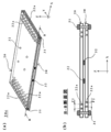
- FIG. 1 It is a schematic diagram which shows the external appearance of the plant illuminating device 100 containing the plant lighting fixture which concerns on 1st Embodiment. It is a schematic diagram which shows typically the side surface at the time of cutting the plant lighting apparatus 100 by XZ plane. It is a schematic diagram which shows light source LS among the illuminating devices 100 for plants. It is a perspective view which shows typically the external appearance of the 1st reflection member 10 among the illuminating devices 100 for plants. It is a perspective view which shows typically the external appearance of the 2nd reflective member 20a among the illuminating devices 100 for plants. It is a schematic diagram explaining the structure of each site
- FIG. 3 is an irradiation schematic diagram schematically showing a state in which a plant is irradiated with UV-B light. It is a schematic diagram which shows the external appearance of the plant illuminating device 100 containing the plant lighting fixture which concerns on 2nd Embodiment. It is a schematic diagram which shows the external appearance of the plant illuminating device 100 containing the plant lighting fixture which concerns on 3rd Embodiment. It is a schematic diagram which shows the external appearance of the plant illuminating device 100 containing the plant lighting fixture which concerns on 4th Embodiment. It is a schematic diagram which shows the detailed structure of the 1st reflection member 10 of the plant illuminating devices 100 containing the plant lighting fixture which concerns on 4th Embodiment.
- FIG. 10 is a perspective view schematically showing the appearance of a second reflecting member 20 and a third reflecting member 30 according to Modification 2.
- FIG. 10 is a perspective view schematically showing the appearance of a second reflecting member 20, a third reflecting member 30, and an optical plate 40 according to Modification 3.
- FIG. FIG. 10 is a perspective view schematically showing the appearance of a second reflecting member 20, a third reflecting member 30, and an optical plate 40 according to Modification 3.
- FIG. 14 is a perspective view schematically showing the appearance of second reflecting members 20d to 20f according to Modification 4. It is a perspective view showing typically the appearance of the 2nd reflective member 20g concerning modification 5. It is a perspective view showing typically the appearance of the 2nd reflective member 20h concerning modification 6 respectively. It is a schematic diagram which shows the structural example of lighting system IS for plants. It is a figure and graph explaining the irradiation simulation which concerns on an Example.
- FIG. 1 is a diagram schematically showing the appearance of a plant lighting device 100 according to the present embodiment.
- the plant lighting device 100 includes at least a light source LS and a plant lighting fixture.
- the lighting fixture for plants in this embodiment is comprised including the 1st reflective member 10 and the 2nd reflective member 20 which are explained in full detail later.
- the light source LS suitable for the present embodiment has a function of irradiating light capable of removing pests that inhibit plant growth.
- the light emitted from the light source LS for example, ultraviolet light is exemplified.
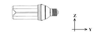
- UV-B light it is desirable that light in the UV-B region (hereinafter also referred to as “UV-B light”) having a wavelength effective for removing the above-mentioned pests be used in the present embodiment.
- UV-B light is used as the light emitted from the light source LS to remove pests.
- the present invention is not limited to this.
- the light in the UV-A region which is a wavelength region that promotes the growth of plants
- light in other wavelength ranges may be used.
- the specific structure of the light source LS is not particularly limited and can be variously applied, such as a lamp or a light bulb having a known shape, but considering the cost and availability, the light bulb type light source illustrated in FIG. (A bulb-type UV lamp having a wavelength of UV-B) is preferable.
- a light bulb type light source may have a light bulb shape.
- a light bulb incandescent bulb
- a light bulb type halogen lamp a light bulb type fluorescent tube
- compact type fluorescent tube a compact type fluorescent tube
- a light bulb type LED etc.
- Various structures may be applied.
- the first reflecting member 10 has one side in the first direction (in the ⁇ Z direction in FIG. 1) with respect to the light source LS that irradiates the UV-B light L. It is arranged on the side (upper side).
- the first reflecting member 10 has a function of reflecting the UV-B light L and guiding it to the other side in the first direction (below the light source LS with respect to the Z direction).
- the “first direction” can also be said to be a direction in which the first reflecting member 10, the light source LS, and the second reflecting member 20 are arranged toward the plant.
- the ⁇ Z direction is the first direction.
- the plant is either in the horizontal direction with respect to the plant lighting device 100.
- the horizontal direction is the first direction.
- the first reflecting member 10 As a specific material of the first reflecting member 10, a material that efficiently reflects the UV-B light L emitted from the light source LS is desirable.
- an aluminum plate material having a high UV-B light reflectance is used.
- the first reflecting member 10 of this embodiment may have a reflectance of UV-B light of 80% or more. This is because when the reflectance of UV-B light is less than 80%, the function of removing pests on plants cannot be sufficiently exhibited.
- aluminum can be used as the material of the first reflecting member 10 from the viewpoint of high reflectivity of UV-B light.
- this material is used. It is not limited to.
- An Al vapor-deposited plate material or an Al-coated plate material obtained by vapor-depositing or coating aluminum may be used.
- a nickel plating layer, a chromium plating layer, a galvanization layer, or the like may be further formed on the surface of the steel plate (the lower layer of the Al layer) to provide an anticorrosion function.
- the surface treatment ST as exemplified above is performed on the surface of the first reflecting member 10 facing the light source LS. It can be said that it is preferable to have been applied.
- specular reflection processing such as mirror finish is exemplified as an example of the surface treatment ST.
- rough surface processing that diffusely reflects the UV-B light L to the surroundings or diffusion coating in which aluminum particles are dispersed.
- a light diffusion treatment such as is further performed. That is, the surface treatment ST suitable for this embodiment may be a surface treatment that causes not only regular reflection but also diffuse reflection.
- the first reflecting member 10 in the present embodiment is required to distribute the UV-B light L so as to be as homogeneous as possible even when installed at a height relatively close to the plant. .
- the first reflecting member 10 has an optimal shape.
- the first reflecting member 10 includes a first inclined surface 11 that is convex downward (the cross section in the X direction is V-shaped) toward the light source LS. It is preferable that the UV-B light L guided from the second reflecting member 20 described later is reflected by the first inclined surface 11.
- the first reflecting member 10 has the convex first inclined surface 11 under the slope that climbs up to the respective outer edges 11b on both sides in the X direction with the central portion 11a as the bottom. is doing.
- the first reflecting member 10 in the present embodiment is obliquely downwardly intersecting with the first inclined surface 11 at each outer edge 11b of the first inclined surface 11 described above. It is further preferable to further include a second inclined surface 12 that is inclined in the direction.
- the first reflecting member 10 in the present embodiment has two peaks such that the central portion 11a is a valley and the two outer edges 11b are ridges in the XZ cross section. It has an articulated shape. Thereby, the UV-B light L guided from at least one of the second reflecting member 20 and the first inclined surface 11 is reflected by the second inclined surface 12 and reaches the back side BS (described later) of the second reflecting member 20. Irradiation is possible.
- the first reflecting member 10 relates to the first direction (Z direction) and the third direction (Y direction) orthogonal to the second direction (X direction). It is more preferable that the end portion 11c on the side away from the light source LS includes the third inclined surface 13 that is folded downward. Also according to this aspect, the UV-B light L guided from at least one of the second reflecting member 20, the first inclined surface 11, and the second inclined surface 12 is reflected by the third inclined surface 13 and is reflected by the second reflecting member 20. It is possible to irradiate up to the back side BS.
- the light source LS of the present embodiment is supported by being suspended from the first inclined surface 11 of the first reflecting member 10 via the mounting plate 14. More specifically, as shown in FIG. 2B and the like, the bottom portion (base portion) of the light source LS is fixed to the mounting plate 14 via the fixing portion 14b.
- the fixing portion 14b there is no restriction
- the power supplied to the light source LS is also wired through the mounting plate 14, and the light source LS is also electrically connected to a commercial power source and a battery (not shown).
- the light bulb-type light source LS is disposed sideways (in a state where the insertion direction of the base with respect to the socket is horizontal).
- the light bulb-type light source LS is installed on the mounting plate 14 so as to lie down so that the insertion direction of the base is the Y direction (in other words, crosses the first direction (Z direction)).
- the 2nd reflection member 20 is explained in full detail among the lighting fixtures for plants in embodiment.
- the second reflecting member 20 is disposed on the opposite side of the first reflecting member 10 in the first direction (Z direction) so as to sandwich the light source LS.
- the light source LS is positioned so as to be sandwiched between the first reflecting member 10 and the second reflecting member 20 in the Z direction.
- the 2nd reflection member 20 in this embodiment is a rectangular plate-shaped body with which the X direction becomes the long side (Hereinafter, this form is described as "the 2nd reflection member 20a.”).
- the second reflecting member 20a of the present embodiment is connected so as to be suspended from the first reflecting member 10 via the connecting member 23 at the lower end periphery of the first reflecting member 10, for example.
- a known fixing means such as screwing or welding may be used.
- the connection mode is more preferably a fixing method such as screwing that is easy to attach and detach.
- the second reflecting member 20a guides a part of the UV-B light L received on its light receiving surface (for example, the surface facing the light source LS) to the first reflecting member 10 side, and receives the light.
- a function of guiding the other part of the UV-B light to the back side BS is provided. That is, as shown in FIG. 5 and the like, the second reflecting member 20a of the present embodiment is arranged so that the above-described restriction region 21 that prohibits the passage of the UV-B light L as it is is opposed to the light source LS. .
- the limited region 21 described above is positioned in a region centered on the center of the second reflecting member 20a.
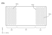
- an adjustment region 22 that allows at least a part of the received UV-B light L to pass directly is arranged outside the restriction region 21 (adjacent region in the ⁇ X direction). More specifically, a plurality of through holes 22a are formed in the adjustment region 22 in the present embodiment.
- the limited region 21 is a through hole non-formed region without forming the through hole 22a, and a reflective surface for reflecting the received UV-B light L is formed.
- the plurality of through holes 22a in the adjustment region 22 are formed in a plurality of rows with a plurality of through holes arranged linearly in the Y direction at a predetermined distance.
- the centers of the through-holes 22a between adjacent rows are shifted in a staggered manner so that the centers are not aligned with each other in the Y direction. Therefore, the UV-B light L guided from the light source LS side to the second reflecting member 20a is reflected by the restriction region 21 and reflected to the first reflecting member 10 side and the like, while the adjustment region 22 The light passes through the inside of the through-hole 22a and does not appear periodically, and is guided to the back side BS of the second reflecting member 20a.
- the “back side BS” is a side opposite to the back side opposite to the surface receiving the UV-B light L from the light source LS, and becomes a shadow when the light source LS emits light. This corresponds to a region (see FIG. 2 and the like).
- the “back side BS” in the present embodiment is directly below the second reflecting member 20 in the vertical direction. It becomes an area to include.
- the limited region 21 in the second reflecting member 20a has a mode in which the UV-B light L is specularly reflected by mirror finishing as described above, and a mode in which the UV-B light L is diffusely reflected by roughing or the like. It may be. Further, as apparent from FIG. 5, the length of the restriction region 21 in the X direction is set to be larger than the length of the adjustment region 22.
- the light guided to the back side BS through the adjustment region 22 can be adjusted as appropriate depending on the number of through holes 22a (area ratio of the through hole portion and the non-through hole portion). Therefore, it is not limited to the above-described mode, and for example, the length of the restriction region 21 in the X direction may be set to be smaller than the length of the adjustment region 22 in the X direction. Alternatively, the length of the restriction region 21 in the X direction may be twice the length of the adjustment region 22. Although the number of through holes 22a varies depending on the size of the second reflecting member 20, the number of through holes 22a in this embodiment may be about 40 to 300 as an example.
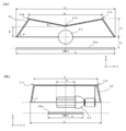
- FIG. 6A shows the size and positional relationship of each member in the X direction and the Z direction. As shown in the figure, the X direction in which the first inclined surface 11 and the second inclined surface 12 are arranged is symmetrical with respect to the central portion 11a.
- the length connecting the two outer edges 11b located on both sides is l 1
- the length l 2 connecting both ends of the first reflecting member 10 and the length of the second reflecting member 20 Is defined as l 3 .
- the distance from the center of the light source LS to the outer edge 11b is h 1
- the length of the perpendicular from the center of the light source LS to the second reflecting member 20 is h 2
- the center of the light source LS the distance to the central portion 11a defined respectively h 3 from.
- an angle formed by the first inclined surface 11 with respect to a horizontal plane (the horizontal plane is parallel to the main surface of the second reflecting member 20 in the present embodiment) is ⁇ , and an angle formed by the second inclined surface 12 with respect to the horizontal plane is ⁇ . It is defined as
- FIG. 6B shows the size and positional relationship of each member in the Y direction and the Z direction. As shown in the figure, in the Y direction, the mounting plate 14 and the light source LS are excluded, and the shape is symmetrical with respect to the center line when the light source LS is regarded as a point light source.
- the length of the second reflecting member 20 is l 4
- the substantial length of the light source LS (the portion irradiated with light)
- both ends of the first reflecting member 10 are connected.
- the connecting length l 6 and the length between the end portions 11c located on both sides are defined as l 7 .
- an angle formed by the third inclined surface 13 with respect to the horizontal plane is defined as ⁇ .
- size is good also as the following range. 275 mm ⁇ l 1 ⁇ 325 mm 375 mm ⁇ l 2 ⁇ 425 mm 195 mm ⁇ l 3 ⁇ 425 mm 120mm ⁇ l 4 ⁇ 250mm 140 mm ⁇ l 5 ⁇ 160 mm 270 mm ⁇ l 6 ⁇ 370 mm 220 mm ⁇ l 7 ⁇ 320 mm 25 ° ⁇ ⁇ 35 ° 55 ° ⁇ ⁇ ⁇ 65 ° 75 ° ⁇ ⁇ ⁇ 85 ° 70 mm ⁇ h 1 ⁇ 80 mm, 40 mm ⁇ h 2 ⁇ 50 mm 30 mm ⁇ h 3 ⁇ 60 mm 30 mm ⁇ h 1 ⁇ h 3 ⁇ 50 mm
- the first reflecting member 10 and the second reflecting member are used. 20 can diffuse and irradiate UV-B light as widely and as homogeneously as possible with respect to a plant located on the back side (directly below) of the second reflecting member 20 by the second reflecting member 20 Also, UV-B light can be irradiated without an excessive amount.
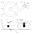
- FIG. 7 is used to schematically show a state in which UV-B light is irradiated to the plant P being cultivated.
- the plant P suitable for the present invention it is suitable for various plants grown in various breeding forms such as soil cultivation and hydroponics.
- Examples of such plants P include leafy vegetables such as lettuce, green leaf, salad vegetables, mizuna, spinach and herbs, fruit vegetables such as eggplant and tomatoes, and fruits that can be cultivated indoors such as strawberries, melons and watermelons. Is suitable.
- the plant P When actual UV-B light is irradiated, the plant P is irradiated with UV-B light from the light source LS in the absence of a person such as at night.
- the UV-B light emitted from the light source LS reaches the plant P through various reflections.
- the following optical path can be exemplified.
- the UV-B light emitted from the light source LS is reflected by the second inclined surface 12 of the first reflecting member 10, and then the adjustment region 22 of the second reflecting member 20.
- the plant P located on the back side BS of the second reflecting member 20 is irradiated.
- the UV-B light emitted from the light source LS is first reflected by the second reflecting member 20, then reflected again by the first reflecting member 10, and then the second reflecting member.
- the plant P is irradiated after reaching the adjustment region 22 of the member 20.
- the UV-B light emitted from the light source LS is reflected by the first inclined surface 11 of the first reflecting member 10 and then enters the adjustment region 22 of the second reflecting member 20. It reaches and is irradiated to the plant P.
- the light emitted from the light source LS repeatedly reflects between the first reflecting member 10 and the second reflecting member 20 or reaches the adjustment region 22 of the second reflecting member 20 as it is.
- the UV-B light received by the second reflecting member 20 the light irradiated to the adjustment region 22 is directed toward the plant P while diffusing to the back side BS of the second reflecting member 20 through the through hole 22a. Irradiated.
- the UV-B light emitted from the light source LS is reflected by the first reflecting member 10 and then is located on the back side BS of the second reflecting member 20. Reach P. Further, as shown by the solid line in FIG. 7B, the UV-B light emitted from the light source LS is first reflected by the second reflecting member 20 and then reflected again by the first reflecting member 10 and then reflected by the plant P. To reach. In addition, as shown by the dotted line in FIG. 7A, the light is first reflected by the first reflecting member 10, then reflected by the second reflecting member 20, and then again reflected by the first reflecting member 10, Thereafter, the plant P is reached.
- the present embodiment is mainly characterized in that it has an outer frame 50 that houses the first reflector 10.
- the length in the X direction of the second reflecting member 20 in the present embodiment is shorter than the length in the X direction of the second reflecting member 20 in the first embodiment.
- the plant lighting apparatus in the present embodiment has an outer frame 50 that functions as a cover member so as to cover the back side of the first reflecting member 10 (the side opposite to the side facing the light source LS). It is comprised including. However, also in the present embodiment, there is no difference in the reflection function of the UV-B light L by the first reflecting member 10 as compared with the first embodiment. Further, as shown in the figure, the length of the first reflecting member 10 and the length of the second reflecting member 20 in the X direction in the first embodiment are substantially the same, but in this embodiment, the outer frame 50 and the second reflecting member 20 are the same. The length in the X direction of 1 reflective member 10 is substantially equal. In the present embodiment, the length of the second reflecting member 20 in the X direction is set to be shorter than the length of the first reflecting member 10 in the X direction.
- the 1st reflection member 10 is being fixed in the form accommodated in the outer frame 50 via the fixed connection parts 51 and 52, as shown in FIG.8 (b).
- the specific fixing method of the fixed connection portions 51 and 52 is not particularly limited, and various known fixing means such as screwing and welding may be used.
- the second reflecting member 20 is connected via the connection portions 53 provided at the four corners of the outer frame 51.
- the specific fixing method of the connecting portion 53 is not particularly limited, and various known fixing means such as screwing or welding a shaft member such as an elongated wire or a round bar at both ends may be used.
- the plant lighting device according to the second embodiment described above and the plant lighting device 100 including the plant lighting device are installed indoors, for example, in a greenhouse or a plant cultivation factory, in addition to the effects of the first embodiment described above. It can be easily installed on the ceiling.
- the second reflecting plate 20a is connected to be suspended from the first reflecting member 10 via the connecting member 23.
- the height changing device 60 and the flexible connection are connected.
- the main feature is that it is suspended from the first reflecting member 10 via the material 61. Note that this feature is not limited to this embodiment, and can be shared by other embodiments and modifications without departing from the spirit of the present invention.
- the position and posture of the second reflecting member 20 with respect to the first reflecting member 10 can be varied at an arbitrary timing.
- the height changing device 60 is installed corresponding to the number of the flexible connecting members 61 and has a function of changing the length of the flexible connecting members 61.
- a known electric reel mechanism can be exemplified.
- the height change apparatus 60 is installed in the four corners of the 1st reflection member 20, it is not restricted to such an installation location. For example, like the connection member 23 of 1st Embodiment, you may install in places other than the four corners of the 1st reflection member 10. FIG.
- the height changing device 60 when such a height changing device 60 requires electric power, for example, a wiring (not shown) is connected to a commercial power source or a battery via the mounting plate 14.
- a wiring (not shown) is connected to a commercial power source or a battery via the mounting plate 14.
- the height changing device 60 is not necessarily limited to the electric type, and may be a manual type that does not require electric power.
- the height changing device 60 if the height changing device 60 is electrically operated, it is preferable in that a plurality of height changing devices 60 can be controlled simultaneously and accurately.
- the flexible connecting member 61 is a flexible wire that can be wound by the height changing device 60, and examples thereof include a known flexible wire and chain. From the viewpoint of preventing the weight from being bulky, the flexible connecting member 61 may be made of a lightweight resin material.
- the height changing device 60 is attached to the four corners of the first reflecting member 10. However, for example, when the outer frame 50 is provided, the height changing device 60 is attached to the outer frame 50.
- the following adjusting method can be adopted.
- an operator installs the plant lighting 100 in an indoor environment such as a greenhouse so that the light source LS is positioned at a specified installation height (for example, a distance of 100 cm or less from the plant P as described later).
- an ultraviolet measurement sensor (not shown) is arranged in an irradiation surface corresponding to the height of the plant P (for example, a surface of 400 cm ⁇ 300 cm, which will be described later), and the intensity and amount of UV-B light are monitored.
- the operator adjusts the distance of the second reflecting member 20a with respect to the first reflecting member 10 by controlling the height changing device 60 via a controller (not shown) while referring to the value of the monitor. At this time, for example, by winding or unwinding the flexible connecting member 61 via the height changing device 60, the second reflecting member 20a is moved closer to or away from the first reflecting member 10.
- the operator fixes the distance of the second reflecting member 20a with respect to the first reflecting member 10 when the best irradiation state is obtained while monitoring the measurement value from the ultraviolet ray measuring sensor.
- the flexible connecting member 61 is simultaneously wound by the same length by the plurality of height changing devices 60, so that the second reflecting member 20a can be moved up and down while maintaining the horizontal posture.
- the posture of the second reflecting member 20a does not necessarily have to be kept horizontal, and the second reflecting member 20a may be controlled to be inclined with respect to the first reflecting member 10 according to the value indicated by the monitor.
- the plant lighting apparatus according to the third embodiment described above and the plant lighting device 100 including the same are, for example, the first reflection member 10 and the second reflection at an arbitrary timing.
- the interval between the members 20 and the posture of the second reflecting member 20 with respect to the first reflecting member 10 can be adjusted.
- the first reflecting member 10 and the second reflecting member 20 having a rectangular shape in plan view are used.
- the first reflecting member 10 is a cone opened downward (on the second reflecting member 20 side when the first reflecting member 10 is used as a reference), the second reflecting member 20.
- main features such as a point or polygonal shape with one interior angle of 108 ° or more in a plan view, and a point that the light source LS is placed vertically rather than horizontally.
- dedicated equipment such as a dedicated suspension wire for the outer frame 50 and the first reflecting member 10 in an installation facility such as a greenhouse.
- the outer frame 50 may be omitted depending on the case in that it can suspend the 20, and it has a form excellent in installation property and cost control while making the above-described dedicated equipment unnecessary as much as possible. .
- the plant lighting apparatus according to the present embodiment and the plant lighting apparatus 100 including the plant lighting fixture are opened downward and directed to the second reflecting member 20a ′ so that the concave cone is recessed at the center.
- a second reflecting member 20 a ′ having a size substantially equal to the outer diameter (described later) of the first reflecting member 10.
- the material of the first reflecting member 10 is not particularly limited, and the same material as in the first embodiment described above can be applied. As will be described later, since the first reflecting member 10 is connected to the mounting portion ST of the light source LS, it is desirable that it be as light as possible. From such a viewpoint, for example, as the material of the first reflecting member 10, a metal foil having a specular reflectivity such as an aluminum foil (further, the inner edge and the outer edge of the first reflecting member 10 are each made of a known reinforcing material such as a wire. It may be reinforced).
- the form of the first reflecting member 10 may be a composite material such as a form in which an aluminum foil is fixed to a lightweight plastic base or a form in which an aluminum foil is fixed to a heat-resistant vinyl sheet, or a lightweight plastic.
- a material in which a specular reflection film such as aluminum or silver is formed on a heat-resistant vinyl sheet may be used.
- the light source LS is preferably used by being suspended from a socket of an electric cord provided in a facility such as a greenhouse. Therefore, in the case where the light source LS is the light bulb type light source shown in FIG. 3, it is preferable that the base portion is vertically upward and the light bulb portion is arranged vertically downward.
- the attachment portion ST provided on the light source LS side may be integrally formed with the light source LS (bulb-type light source), for example, but is not limited to this form, and may be installed on the socket side of the illumination cord, for example. .
- the attachment portion ST similarly to the structure disclosed in Japanese Patent Application Laid-Open No. 2016-131526, a configuration in which the mounting portion ST is provided in a part of the light source LS (bulb-type light source) is employed.
- the specific connection form between the attachment portion ST and the connection member FM is not limited to the attachment method disclosed in the above-mentioned Japanese Patent Application Laid-Open No. 2016-131526, and other known attachments such as press-fitting and fitting. Techniques can be applied.
- connection member FM is a ring-shaped flat plate in which an opening OP into which a light source LS (bulb-type light source) can be inserted is formed.
- the material of such a connection member FM is not particularly limited as long as it is strong enough to support the first reflecting member 10, and examples thereof include known metals such as aluminum and steel plates or known resin materials.
- the light source LS-side mounting portion ST is connected to the inner peripheral side FM 1 of the connection member FM, and the first reflecting member 10 is connected to the outer peripheral side FM 2 .
- An opening 15 (diameter: l 13 ) is connected.
- the connection between the connection member FM and the attachment portion ST is as described above, but the connection between the connection member FM and the first reflecting member 10 is a known non-detachable connection using, for example, welding or an adhesive. A fixing method can be adopted.
- the first reflecting member 10 in the present embodiment has a circular shape in plan view, and a first inclined surface 11 that is recessed downward, and is directed downward on the outside of the first inclined surface 11. And a second inclined surface 12 that spreads out.
- the 1st reflective member 10 of this embodiment also has the convex 1st inclined surface 11 on the bottom which became the climbing slope from the center part to the outer edge 11b similarly to 1st Embodiment. It can be said that.
- connection opening 15 for connecting to the attachment portion ST provided on the light source LS side is formed in the bottom portion (center in the first inclined surface 11) of the center of the first reflecting member 10.
- the connection opening 15 is a circular hole having a size into which the above-described light source can be inserted.
- the connection opening 15 is a circular hole.
- the connection opening 15 is not necessarily circular and may be, for example, a rectangular opening.
- the second inclined surface 12 arranged outside the first inclined surface 11 is a downward inclined surface that spreads outward from the outer edge 11b of the first inclined surface 11 in the radial direction. It is connected to the outer edge 11b.
- the second inclined surface 12 has a mortar-shaped form in which the opening is widened toward the second reflecting member 20a ′ starting from the outer edge 11b. Therefore, in this embodiment, as shown in FIG. 11, the inner diameter l 14 formed by the outer edge 11 b is configured to be smaller than the outer diameter l 11 formed by the lower end 12 e of the second inclined surface 12.
- the outer diameter l 11 at the lower end 12 e of the second inclined surface 12 in the first reflecting member 10 is larger than the outer diameter l 10 of the second reflecting member 20 a ′. It is preferable to be configured to be slightly smaller. In other words, as shown in FIG. 10B, the second reflecting member 20a ′ of the present embodiment is configured to be inscribed in the first reflecting member 10 in plan view.
- the second reflecting member 20a ′ of the present embodiment has a polygonal or circular structure in plan view. Therefore, the above-mentioned “outer diameter of the second reflecting member 20a ′” is “l 10 ” defined by a diagonal line passing through the center when the second reflecting member 20a ′ has a polygonal shape in plan view. Defined. More specifically the second reflecting member 20a' of this embodiment is a planar view octagonal, length of a perpendicular from the center to the sides is almost a half of the outer diameter l 11 (FIG. 10 (See (b)).
- the first reflecting member 10 and the second reflecting member 20a ′ can diffuse and irradiate UV-B light as widely and as homogeneously as possible, and yet the second reflecting member 20a ′.
- the first reflecting member 10 and the second reflecting member 20a ′ can diffuse and irradiate UV-B light as widely and as homogeneously as possible, and yet the second reflecting member 20a ′.
- the second reflecting member 20a ′ is arranged so as to face the opening defined by the lower end 12 e of the second inclined surface 12 in the first reflecting member 10.
- the material and thickness of such 2nd reflection member 20a ' it can apply similarly to the said 1st Embodiment etc., respectively.
- the second reflecting member 20 a ′ is suspended via the connecting member 23 so as to be detachable from the first reflecting member 10 at an arbitrary timing. More specifically, the first reflecting member 10 is suspended from the lower end 12 e of the second inclined surface 12 via the connecting member 23. Therefore, for example, when only the second reflecting member 20a ′ is deteriorated due to an unintended factor, a new second reflecting member 20a ′ may be prepared and appropriately replaced.
- Fig.10 (a) although 2nd reflection member 20a 'is connected with the 1st reflection member 10 via the total three connection members 23 in this embodiment, it is not restricted to this form. .
- the second reflecting member 20 a ′ may be suspended by three or more connecting members 23, or by a single connecting member 23. It may be suspended. Furthermore, in order to finely adjust the irradiation distribution, it is preferable that the hanging position of the second reflecting member 20a ′ can be adjusted.
- the second reflecting member 20a ′ of the present embodiment is provided with a restriction region 21 and an adjustment region 22 as in the first embodiment.
- an adjustment region 22 having a plurality of through holes 22a is formed on the peripheral side of the second reflecting member 20a ′ in plan view.
- the center O of the second reflecting member 20a' as standards, restricted area 21 or the length of at least l 8 is formed.
- the distance between the first reflecting member 10 and the second reflecting member 20a ′ can be set according to the irradiation characteristics of the UV-B light irradiated to the plant P.
- the outside diameter of the first reflecting member 10 corresponding to the outer diameter l 11 of the lower end 12e
- placing a second reflecting member 20a' to the distance from the lower end 12e of about 120mm Can be illustrated.
- the distance of the second reflecting member 20a ′ with respect to the first reflecting member 10 or the light source LS may be set in view of the following viewpoints. That is, the illuminance of the UV-B light irradiated from the light source LS to the central portion (near the second reflecting member 20a ′) increases as the distance between the second reflecting member 20a ′ and the light source LS decreases. Conversely, if the distance from the light source LS is increased, the illuminance at the center tends to decrease.
- the irradiation distribution of the UV-B light can also be adjusted by the aperture ratio of the second reflecting member 20a ′ by the through-hole 22a and the width of the restricted region 21 of the second reflecting member 20a ′. For this reason, it is desirable to adjust the distance from the light source LS (center) to the second reflecting member 20a ′ within a range of 50 mm to 150 mm, for example.
- the size of the through hole 22a in the adjustment region 22 is excessively large, the intensity of light toward the center on the back side of the second reflecting member 20a ′ becomes too strong, and therefore, depending on the characteristics of the plant P to be irradiated. It is preferable to adjust appropriately.
- the density of the through holes 22a in the adjustment region 22 is substantially uniform in the circumferential direction, but is not limited to this form.
- the size (hole diameter) of the through holes 22a may be varied with respect to the circumferential direction, or the number of the through holes 22a may be changed.
- the outer shape of the second reflecting member 20 a ′ of the present embodiment is preferably a polygonal shape or a circular shape in plan view corresponding to the first reflecting member 10. More specifically, the second reflecting member 20a ′ may be a polygon having one interior angle ⁇ i of 108 ° or more in plan view, and the interior angles thereof may be equal to each other. As a result of intensive studies from such a point of view, in the present embodiment, a configuration in which the external shape of the second reflecting member 20a ′ is a regular octagon in plan view with an internal angle of 135 ° is employed.
- a regular quadrangle or a regular hexagon may be applied as the outer shape of the second reflecting member 20a ′, and the inner angles of the second reflecting member 20a ′ may be completely matched without departing from the spirit of the present embodiment. It does not have to be.
- the outer diameter D 1 of the first reflecting member 10 (corresponding to the outer diameter l 11 at the lower end 12e) and the minimum diameter D 2 of the limiting region 21 of the second reflecting member 20a ′ (l 11 ⁇ (2 ⁇ l 9 ) , or for the relationship between the equivalent) to l 8, it can be set based on the following aspects. That is, the irradiation distribution of the UV-B light varies depending on the distance between the second reflecting member 20a ′ and the light source LS, the aperture ratio due to the through hole 22a, and the like, but the illuminance at the center is not extremely high. As an example, (D 2 / D 1 )> 1/2 is preferably satisfied, and (D 2 / D 1 )> 2/3 is more preferable.
- the second reflecting plate 20 a ′ is connected so as to be suspended from the first reflecting member 10 via the connecting member 23 having a fixed length, but is not limited to this form. That is, as described in addition to being applicable to other embodiments, the second reflecting member 20a of the present embodiment is replaced by the height changing device 60 and the flexible connecting member 61 of the third embodiment instead of the connecting member 23. ' May be configured to be suspended from the first reflecting member 10.
- the outer shape of the second reflecting member 20a ′ of the present embodiment is a polygonal shape or a circular shape in plan view, but for example, the same shape as the outer shape in plan view of the first reflecting member 10 (in this example, (Circle shape) is good.
- the light source LS inserted in the socket of the illumination cord is as if the conventional lamp shade. (Lamp shade) can be installed simply as if attached. Therefore, the user only has to wire a known lighting cord in a facility such as a greenhouse, and the installation cost and labor can be greatly reduced.
- the second reflecting member 20a or 20a 'in the first to fourth embodiments described above guides a part of the received UV-B light to the first reflecting member 10 side and receives the received UV-B light. The other part is guided to the back side of the second reflecting member 20a or 20a '.
- the UV-B light can be diffused and irradiated as uniformly as possible in a wide range, and the second reflecting member 20 can also irradiate the plant P located immediately below without excessive UV-B light. It has become.
- FIG. 14 shows a modification of the second reflecting member 20 that can be applied to each of the above-described embodiments.
- the second reflecting member 20b shown in the figure has the same structure of the restriction region 21 as the second reflecting member 20 described in the first to fourth embodiments, but the structure of the adjustment region 22 is different. Yes.
- an optical member 24 that incorporates a part of the UV-B light L that can be transmitted while the other part is transmitted.
- a half mirror, soda-lime glass, quartz glass, fluorite, or the like can be used. That is, as the material of the optical member 24, an optimal glass material can be selected according to the degree of reflection, transmission, or attenuation.
- the limited region 21 may be subjected to a surface treatment ST that allows efficient diffusion and regular reflection, as in the above-described embodiment.
- the amount of passing light is controlled by the area ratio of the through-hole forming region and the through-hole non-forming region by forming the through-hole 22a in the adjustment region 22.
- the passing light amount is adjusted by the attenuation amount of the UV-B light in the region 22.
- the width of the restriction region 21 in the X direction is set to be wider than the width of the adjustment region 22. However, these may be the same width or the width of the adjustment region 22. May be set to be wider.
- FIG. 15 shows another modification that can be applied to the above-described embodiments. That is, the present modification 2 is mainly characterized in that the third reflecting member 30 is further provided below the second reflecting member 20 described in the first to fourth embodiments.
- the plant lighting fixture further includes a third reflecting member 30 that is disposed below the second reflecting member 20 and diffuses the UV-B light that has passed through the second reflecting member 20 downward. May be.
- the third reflecting member 30 of the present modification has substantially the same shape with respect to the second reflecting member 20 except that the formation position of the through hole 22a is different.
- the second reflecting member 20 and the third reflecting member 30 are connected to each other through a known fastening means 31 such as a combination of a bolt and a nut, and the distance between them is made constant via a spacer 32.
- a known fastening means 31 such as a combination of a bolt and a nut, and the distance between them is made constant via a spacer 32.
- the specific material of the spacer 32 is not particularly limited, and various known materials such as a resin material and a metal material may be used.
- the second reflecting member 20 and the third reflecting member 30 when the second reflecting member 20 and the third reflecting member 30 are arranged to face each other with a predetermined gap (the thickness of the spacer 32) in the Z direction,
- the plurality of through holes 22a formed in the adjustment region 22 are arranged so as not to overlap each other in the Z direction.
- the through holes 22a of the second reflecting member 20 and the third reflecting member 30 are arranged so as not to partially overlap each other.
- the present invention is not limited to this example, and at least one through hole in the Z direction is the other. It may overlap partially on the condition that it is not completely included in the through hole.
- the light that has passed through the adjustment region 22 of the second reflecting member 20 is further irradiated to the back side BS via the adjustment region 22 of the third reflecting member 30.
- the light that has passed through the adjustment region 22 of the second reflecting member 20 passes through the adjustment region 22 of the third reflecting member 30 after being repeatedly reflected between the second reflecting member 20 and the third reflecting member 30.
- the intensity of the UV-B light since the optical path of the UV-B light becomes relatively long, the intensity of the UV-B light also decreases accordingly, and the UV-B light whose intensity is appropriately reduced becomes the back side BS.
- the plant P located at is reached.
- region 21 may exist and may be abbreviate
- the third reflecting member 30 has substantially the same shape as the second reflecting member 20 except that the formation position of the through-hole 22a is different. May be made smaller and the size of the adjustment region 22 may be enlarged accordingly. As a result, the light that has passed through the adjustment region 22 of the second reflecting member 20 repeatedly reflects with the third reflecting member 30 and reaches the vicinity of the center, and then passes through the adjustment region 22 of the third reflecting member 30. The back side BS is irradiated.
- the pitch P1 between the through holes 22a of the second reflecting member 20 may be the same as the pitch P2 between the through holes 22a of the third reflecting member 30, or may be different from each other.
- the second reflecting member 20 may be the above-described second reflecting member 20a or the second reflecting member 20b.
- the inner diameter of the through hole 22a of the third reflecting member 30 may be the same as the inner diameter of the through hole 22a of the second reflecting member 20, or may be different from each other.
- the third reflecting member 30 may not have the through hole 22a as long as it has a function of diffusing UV-B light received via the second reflecting member 20 to the back side BS.
- the third reflecting member 30 for example, a known optical material plate such as a half mirror having a transmission function and a reflection function or a fluorine sheet capable of efficiently transmitting ultraviolet rays may be applied.
- the spacer 32 was used in this modification, you may abbreviate
- FIG. 16 shows another modification that can be applied to each of the above-described embodiments. That is, the present modification 3 is mainly characterized in that the spacer 32 is excluded from the modification 2 described above and an optical plate 40 is further provided.
- the optical plates 40 are connected to each other via the fastening means 31 so as to be sandwiched between the second reflecting member 20 and the third reflecting member 30.
- the optical plate 40 is a plate-like body having substantially the same outer shape as the second reflecting member 20 described above.
- the thickness of the optical plate 40 may be substantially the same as that of the second reflecting member 20 or the third reflecting member 30 described above, may be set thinner than these, or may be set to be thicker. .
- Such an optical plate 40 can be made of various materials as long as UV-B light can be transmitted, and examples thereof include glass materials and transparent resin materials.
- the glass material is preferably quartz glass or fluorite from the viewpoint of transmitting UV-B light as much as possible, but it may be a glass material that partially transmits in view of cost.
- the resin material include acrylic resin that can transmit UV-B light.
- This modification 3 can also achieve the same effect as the modification 2 described above, and even if the spacer 32 is omitted, the gap between the second reflecting member 20 and the third reflecting member 30 is maintained uniformly. It is possible.
- FIG. 17 shows another modification that can be applied to the above-described embodiments. That is, in the fourth modification, an arrangement form of the through holes 22a that can be applied as the second reflecting member 20 and other examples that can be applied as the outer shape of the second reflecting member 20 are shown.
- the through hole 22 a may be formed not only in the adjustment region 22 but also in the vicinity of the outer edge of the restriction region 21 (near the end in the ⁇ Y direction). In this case, it becomes the form arrange
- the second reflecting member 20 may be a plate-like body having a square plan view. That is, the second reflecting member 20 can be in a plate state having a polygonal shape or a circular shape in plan view such as the octagon described in the fourth embodiment.
- the second reflecting member 20 is not limited to a polygonal shape or a circular shape in plan view, and may be in an elliptical plate state as shown in FIG. Also, in FIGS. 17B and 17C, the through hole 22a may be formed on the outer edge of the restriction region 21 as in the case of FIG.
- FIG. 18 shows another modification that can be applied to the above-described embodiments.
- the second reflecting member 20 has a flat plate shape.
- the second reflecting member 20 has a main feature in that it is a plate-like body that is bent. .
- That second reflecting member 20h in first FIG. 18 (a), has a convex bent plate inclined obliquely laterally from the top 20h 1 becomes end 20h 2.
- the second reflecting member 20h when viewed in the XZ plane, and has a chevron shape that the top 20h 1 and ridge.
- the vicinity of the center is the restriction region 21 while the periphery is the adjustment region 22.
- the through-holes 22a formed in the adjustment region 22, the hole diameter is adapted to expand toward the end 20h 2.
- the plurality of through-holes 22a formed in the adjustment region 22 in the above-described embodiments and modifications may not necessarily have the same hole diameter, but may have different hole diameters so as to gradually expand toward the end or the outer edge. can do.
- the second reflection member 20h in FIG. 18 (b), inclined obliquely has a concave bent plate comprising an end portion 20h 2 laterally from the bottom 20h 1.
- the second reflecting member 20h when viewed in the XZ plane, and has a valley shape the bottom 20h 1 was a valley.
- the 2nd reflection member 20 does not necessarily need to be a flat board, for example, may be a bending board like this modification.
- the 2nd reflection member 20h of this modification was a board which bends one place of a center part, it is good also as a bending board (W shape or M shape) which has a bending part twice or more.
- the top 20h 1 and the bottom 20h 1 are formed as many times as the number of times of folding.
- FIG. 19 shows another modification that can be applied to each of the above-described embodiments.
- the second reflecting member 20 i shown in the figure is characterized in that a light scattering plate 22 b is further provided for the through hole 22 a formed in the adjustment region 22.
- the light scattering plate 22b is formed with a slit having a contour shape to be the light scattering plate 22b in the adjustment region 22 of the second reflecting member 20, and the light is emitted simultaneously with the through-hole 22a by raising an inner portion of the slit.
- the scattering plate 22b can be formed.
- JP-A-2016-225292 may be referred to as appropriate.
- FIG. 20 shows a configuration example of the plant lighting system IS.
- plants P cultivated in an indoor environment such as a greenhouse are often cultivated in a plurality of rows at a predetermined distance. Therefore, rather than being used alone in the indoor environment described above, a plurality of plant lighting devices 100 are used such that a part of each irradiation range IR overlaps.
- a plurality of plant illumination devices 100 having the same irradiation range are used, but not limited to this, illumination characteristics (for example, orientation and intensity, Alternatively, a plurality of plant lighting devices 100 having an irradiation range or the like may be used.
- FIG. 21 (a) shows a graph of the amount of light by simulation of the plant illumination system IS in a state where nine plant illumination devices 100 are prepared and suspended.
- the area of the measurement surface in the plant illumination system IS was set to 1080000 cm 2 with 1200 cm in the horizontal direction (X direction) and 900 cm in the vertical direction (Y direction).
- the maximum illuminance in the above-described measurement surface was about 240 lux (lx), and the average illuminance was about 65 lux (lx).
- FIG. 21B shows a graph of the amount of light by simulation of the plant lighting device 100 alone.
- the area of the measurement surface in the plant lighting device 100 alone was set to 1200 cm 2 with 400 cm in the horizontal direction (X direction) and 300 cm in the vertical direction (Y direction).
- the maximum illuminance in the above-described measurement surface was about 220 lux (lx), and the average illuminance was about 50 lux (lx).
- the maximum intensity (estimated) of approximately 22 ⁇ W / cm 2, mean intensity in the measuring plane (estimated) it became 5 W / cm 2.
- the plant lighting device 100 capable of solving the above-described problems is a UV-B light in an irradiation range of 400 cm ⁇ 300 cm separated by 75 cm downward from the light source LS.
- the maximum intensity was 30 ⁇ W / cm 2 or less and the average intensity was 5 to 10 ⁇ W / cm 2 . This is because if the maximum intensity of the UV-B light exceeds 30 ⁇ W, the intensity of the UV-B light guided to the back side of the second reflecting member 20 is too strong, and there is a high possibility of causing leaf burning.
- the average intensity of UV-B light is less than 5 ⁇ W, a region where the intensity of UV-B light necessary for the removal of pests cannot be obtained in the above-mentioned irradiation range occurs, whereas if it exceeds 10 ⁇ W. This is because the intensity of the UV-B light is so strong that a region where leaf burning occurs can occur.
- the desirable intensity of UV-B light capable of removing pests is 2.5 ⁇ W / cm 2 or more (from International Publication No. WO2017 / 208906).
- the horizontal direction XY plane direction
- UV-B light from the light source LS is diffused in all directions so as to be as homogeneous as possible, and a necessary and sufficient amount of UV-B light can be supplied to the plant to be cultivated. Proved.
- the plant lighting apparatus, the plant lighting apparatus, and the plant lighting system of the present invention can be widely applied in the plant cultivation field regardless of the type of plant.
Landscapes
- Life Sciences & Earth Sciences (AREA)
- Biodiversity & Conservation Biology (AREA)
- Botany (AREA)
- Ecology (AREA)
- Forests & Forestry (AREA)
- Environmental Sciences (AREA)
- Cultivation Of Plants (AREA)
Abstract
【課題】比較的低い高さに設置しても広範で可能な限り均質にUV-B光を照射でき、それでいて直下の植物に対しても過度にUV-B光が照射されることを抑制可能な植物用照明器具及び植物用照明装置を提供する。 【解決手段】本発明の植物用照明器具は、UV-B光を照射する光源に対して第1方向における一方の側に配置され、前記UV-B光を前記第1方向における他方の側に導く第1反射部材と、前記光源を挟むように前記第1方向に関して前記第1反射部材とは反対側に配置され、受光した前記UV-B光のうちの一部を前記第1反射部材の側へ導くとともに、前記受光したUV-B光のうちの他部を裏側へ導く前記第2反射部材と、を含む。
Description
本発明は、植物用照明技術に関し、より詳細には植物に対して害を為す病害虫を除去するための植物用照明器具及び植物用照明装置に関する。
近年では、自然環境に大きく依存した従来型の農業に対し、エレクトロニクスを融合させることで農作物の生産効率を飛躍的に向上させる開発が進んでいる。例えば植物の成長に対して病害虫は脅威であるが、従来の薬剤散布に代えて人工的な光を用いてこの病害虫を除去するシステムなどが提案されつつある。
例えば特許文献1では、植物の病害虫対策として有効な紫外光の一種であるUV-B光を用いることが提案されている。より具体的にこの特許文献1では、植物の成長に応じて配光を容易に制御できるとともに植物が成長して装置に近づいた場合に植物に葉焼け障害を生じないようにすることができる照明装置が開示されている。
また、特許文献2では、同様にUV-B光を利用して植物病害を低減する装置において、その図3に示されるように、光源2から放出される光を植物Pに直接あたらないようにして光源2から放出される光は全て反射板4で反射されるように構成することが提案されている。同様に特許文献3においても、植物Pに対して紫外光を含む光を照射する光源2と、光源2からの光を植物Pの方向に反射する半楕円筒の反射板3と、光源2から反射板3に反射されずに植物Pに直接照射される光の光路上に配置される紫外光遮断性を有した光学部材4とを備える照明装置が提案されている。
一方で特許文献4では、UV-B光でなく赤外線の照射制限に関する文献であってその技術分野が異なるのではあるが、水平面上に広がるように並置して植えられた植物に対して直下の植物に対する赤外線の照射量を制限する構成が開示されている。
しかしながら、上記した特許文献を含む既存の技術では、植物の病害虫除去としてある程度の効果は挙げているものの、少なくとも下記の点においては未解決であって改善の余地は未だにあると言える。
すなわち、例えば上記特許文献3などにも開示されているように、植物育成では一般的に複数の植物列(畝なども同様)が水平に並んで植えられることが多い。また、例えばイチゴのビニールハウス内での栽培においては、人が歩行可能な通路に沿って延びるプランターが当該通路を挟んで複数並置されることが一般的である。
すなわち、例えば上記特許文献3などにも開示されているように、植物育成では一般的に複数の植物列(畝なども同様)が水平に並んで植えられることが多い。また、例えばイチゴのビニールハウス内での栽培においては、人が歩行可能な通路に沿って延びるプランターが当該通路を挟んで複数並置されることが一般的である。
そして上記のようなハウス栽培ではイチゴ狩りなど植物を気軽に採取できる状態とすることもニーズとしてあることから、上記した特許文献などの照明装置を用いて農薬を極力使用せずに病害虫を除去することは有意義であることは間違いない。
しかしながらこのようなハウス栽培を含む屋内栽培においては、スペース効率を向上させ又は維持コストを節約する観点などから、照明器具の設置高さに制限が設けられることがある。一方で屋内栽培では出来るだけ植物を並置させたいニーズも強く、水平面上に出来るだけ広範囲にUV-B光が届くように照射して病害虫を除去しつつ、加えて直下の植物に対しては葉焼けを防止するため過度な照射は避けねばならない。
しかしながらこのようなハウス栽培を含む屋内栽培においては、スペース効率を向上させ又は維持コストを節約する観点などから、照明器具の設置高さに制限が設けられることがある。一方で屋内栽培では出来るだけ植物を並置させたいニーズも強く、水平面上に出来るだけ広範囲にUV-B光が届くように照射して病害虫を除去しつつ、加えて直下の植物に対しては葉焼けを防止するため過度な照射は避けねばならない。
このように照明の設置高さが低くなると照射範囲は狭くなってしまうが、このような場合でも植物の葉焼けを回避しながら直下を含めて広範にUV-B光を照射できる構成は未だに提案されておらず、上記した特許文献に記載の技術をそのまま適用することができないという課題がある。
本発明は、かような課題を解決することを一例に鑑みてなされたものであり、比較的低い高さに設置しても広範にUV-B光を照射でき、それでいて直下の植物に対しても過度にUV-B光が照射されることを抑制可能な植物用照明器具及び植物用照明装置を提供することを目的とする。
上記課題を解決するため、本発明の一実施形態にかかる植物用照明器具は、(1)UV-B光を照射する光源に対して第1方向における一方の側に配置され、前記UV-B光を前記第1方向における他方の側に導く第1反射部材と、前記光源を挟むように前記第1方向に関して前記第1反射部材とは反対側に配置され、受光した前記UV-B光のうちの一部を前記第1反射部材の側へ導くとともに、前記受光したUV-B光のうちの他部を裏側へ導く前記第2反射部材と、を含むことを特徴とする。
なお上記した(1)に記載の植物用照明器具においては、(2)前記第1反射部材は、前記光源に向けて下に凸状の第1傾斜面を含んで構成され、前記第2反射部材から導かれた前記UV-B光が前記第1傾斜面で反射されることが好ましい。
また上記した(2)に記載の植物用照明器具においては、(3)前記第1反射部材は、前記第1傾斜面の外縁で当該第1傾斜面と山なりに交差して傾斜する第2傾斜面をさらに有し、前記第2反射部材と前記第1傾斜面の少なくとも一方から導かれた前記UV-B光が前記第2傾斜面で反射されて前記第2反射部材の裏側に照射されることが好ましい。
また上記した(3)に記載の植物用照明器具においては、(4)前記第1反射部材は、前記第1方向及び前記第1傾斜面と前記第2傾斜が並ぶ第2方向と直交する第3方向に関し、前記光源から離間した側の端部が前記下方に折り返された第3傾斜面を含んで構成されていることが好ましい。
また上記した(3)に記載の植物用照明器具においては、(5)前記第1反射部材は、前記第2反射部材に向けるよう下方に開口した錐体であり、前記錐体における中央には前記光源が挿入可能な接続用開口が形成されてなることが好ましい。
このとき上記した(5)に記載の植物用照明器具においては、(6)前記第1反射部材は、平面視が円形であって、前記下方に向けて窪んだ第1傾斜面と、この第1傾斜面の外側で前記下方に向けて据え広がる第2傾斜面と、を有して構成されているとよい。
さらに上記した(5)又は(6)に記載の植物用照明器具においては、(7)前記第1反射部材の下端における外径と、前記第2反射部材の外径は、互いに実質的に等しくなるように構成されていることが好ましい。
また、上記した(5)~(7)のいずれかに記載の植物用照明器具においては、(8)前記第2反射部材は、平面視において1つの内角が108°以上の多角形又は円形であるように構成されていることが好ましい。
また上記した(1)~(8)のいずれかに記載の植物用照明器具においては、(9)少なくとも前記光源と向く側における前記第1反射部材の表面には、受光した前記UV-B光を拡散反射させる表面処理が施されてなることが好ましい。
また上記した(1)~(9)のいずれかに記載の植物用照明器具においては、(10)前記第2反射部材は、前記UV-B光がそのまま通過することを禁止する制限領域が前記光源と対向するように配置され、前記制限領域の外側には、受光した前記UV-B光の少なくとも一部が直接通過することを許容する調整領域が配置されていることが好ましい。
また上記した(10)に記載の植物用照明器具においては、(11)前記調整領域には複数の貫通孔が形成され、前記制限領域には前記貫通孔が形成されず受光した前記UV-B光を反射する反射面が形成されていることが好ましい。
また上記した(1)~(11)のいずれかに記載の植物用照明器具においては、(12)前記第2反射部材の下方に配置されて、前記第2反射部材を通過した前記UV-B光を前記下方に向けて拡散させる第3反射部材をさらに含むことが好ましい。
また上記した(12)に記載の植物用照明器具においては、(13)受光した前記UV-B光の少なくとも一部を通過させる複数の貫通孔が前記第2反射部材に形成されるとともに、前記鉛直方向に関して前記第2反射部材の貫通孔と重ならないように複数の貫通孔が前記第3反射部材に形成されていることが好ましい。
また上記した(1)~(4)のいずれかに記載の植物用照明器具においては、(15)前記第1反射部材は、平面視が長方形であって、当該長方形の長辺方向に関し、前記光源に対して直上の位置を底部とした下に凸状の第1傾斜面と、前記第1傾斜面の外縁で折り返されるように傾斜する第2傾斜面と、を含んで構成され、前記長辺方向に関する前記第2反射部材の長さは、前記第1傾斜面の一方の外縁から他方の外縁までの長さよりも大きいことが好ましい。
また上記した(1)~(14)のいずれかに記載の植物用照明器具においては、(15)前記光源からの距離が0.75mを通る前記第1方向と直交する平面における前記光源からの距離が0.75mを通る前記第1方向と直交する平面における400cm×300cmの照射範囲における前記UV-B光の最大強度が30μW/cm2以下であって、且つその平均強度が5~10μW/cm2であることが好ましい。
また、上記した課題を解決するため、本発明の一実施形態にかかる植物用照明装置は、(16)上記した(1)~(15)のいずれかに記載の植物用照明器具と、前記UV-B光を照射する電球型光源と、を含むことを特徴とする。
本発明によれば、比較的低い高さに設置したとしても第1反射部材と第2反射部材によって広範で可能な限り均質にUV-B光を拡散照射でき、それでいて第2反射部材によって直下に位置する植物に対してもUV-B光を過度とならずに照射することが可能となる。
以下、本発明を実施するための実施形態について説明する。なお説明の便宜上、X、YおよびZ軸をそれぞれの図中で設定したが、これら方向付けは本発明の技術的範囲を何ら制限するものではない。
≪第1実施形態≫
図1~図6を用いて本発明の第1実施形態について説明する。
図1は、本実施形態に係る植物用照明装置100の外観を模式的に示した図である。同図に示すように、植物用照明装置100は、光源LSと、植物用照明器具とを少なくとも含んでいる。このうち本実施形態における植物用照明器具は、後に詳述する第1反射部材10及び第2反射部材20を少なくとも含んで構成されている。
図1~図6を用いて本発明の第1実施形態について説明する。
図1は、本実施形態に係る植物用照明装置100の外観を模式的に示した図である。同図に示すように、植物用照明装置100は、光源LSと、植物用照明器具とを少なくとも含んでいる。このうち本実施形態における植物用照明器具は、後に詳述する第1反射部材10及び第2反射部材20を少なくとも含んで構成されている。
図3などに示すように、本実施形態に好適な光源LSは、植物の成長を阻害する病害虫を除去可能な光を照射する機能を備えている。この光源LSが照射する光としては、例えば紫外光が例示される。このうち、特に上記した病害虫を除去するために有効な波長を有するUV-B領域の光(以下、「UV-B光」とも称する)が本実施形態で使用されることが望ましい。
なお、本実施形態では病害虫除去のため光源LSから照射される光はUV-B光を用いたが、この形態に限られず、例えば植物の成長を助長する波長域であるUV-A領域の光やその他の波長域の光を用いてもよい。
なお、本実施形態では病害虫除去のため光源LSから照射される光はUV-B光を用いたが、この形態に限られず、例えば植物の成長を助長する波長域であるUV-A領域の光やその他の波長域の光を用いてもよい。
また、具体的な光源LSの構造としては、特に制限はなく公知の形状を備えたランプや電球など種々適用可能であるが、コストや入手の容易さを考慮すると図3に例示した電球型光源(UV-Bの波長を有する電球型UVランプ)が好適である。また、かような電球型光源としては、外形が電球状であればよく、例えば電球(白熱球)の他に、電球型ハロゲンランプ、電球型蛍光管、コンパクト形蛍光管、電球型LEDなど公知の種々の構造を適用してもよい。
次に、図を適宜参照しつつ本実施形態における植物用照明器具の各構成要素について説明する。
まず第1反射部材10は、図1、2及び4などに示されるように、UV-B光Lを照射する光源LSに対して第1方向(図1の場合は-Z方向)における一方の側(上方の側)に配置される。かような第1反射部材10は、UV-B光Lを反射して第1方向における他方の側(Z方向に関して光源LSよりも下方)に導く機能を有している。
ここで「第1方向」とは、上記した第1反射部材10、光源LS及び第2反射部材20が植物に向けて並ぶ方向とも言える。本実施形態では植物用照明装置100の鉛直方向下方に植物が配置されることから-Z方向が第1方向となっているが、仮に植物が植物用照明装置100に対して水平方向のいずれか側(図1のX方向やY方向)に配置される場合には当該水平方向が第1方向となる。
まず第1反射部材10は、図1、2及び4などに示されるように、UV-B光Lを照射する光源LSに対して第1方向(図1の場合は-Z方向)における一方の側(上方の側)に配置される。かような第1反射部材10は、UV-B光Lを反射して第1方向における他方の側(Z方向に関して光源LSよりも下方)に導く機能を有している。
ここで「第1方向」とは、上記した第1反射部材10、光源LS及び第2反射部材20が植物に向けて並ぶ方向とも言える。本実施形態では植物用照明装置100の鉛直方向下方に植物が配置されることから-Z方向が第1方向となっているが、仮に植物が植物用照明装置100に対して水平方向のいずれか側(図1のX方向やY方向)に配置される場合には当該水平方向が第1方向となる。
具体的な第1反射部材10の材質としては、光源LSから照射されるUV-B光Lを効率的に反射させる材料が望ましく、本実施形態ではUV-B光の反射率が高いアルミニウム板材を採用することができる。例えば本実施形態の第1反射部材10は、特にUV-B光の反射率が80%以上であってもよい。UV-B光の反射率が80%未満であると植物に対する病害虫除去としての機能が充分に発揮できないからである。
なお本実施形態では第1反射部材10の材質としてUV-B光の反射率が高いという観点からアルミニウムを用いることができるが、UV-B光の反射率が80%以上確保する限りにおいてこの材質に限定されない。また、第1反射部材10は、少なくとも表面がUV-B光の反射率を80%以上確保できていればよいので、例えば鏡面処理などした金属材や鋼板などの面(光源LSと対向する面)にアルミニウムを蒸着やコーティングしたAl蒸着板材やAlコーティング板材を用いてもよい。この場合、さらに鋼板の表面(Al層の下層)にはニッケルめっき層やクロムめっき層あるいは亜鉛めっき層などを形成して防食機能を持たせてもよい。
このような観点から、本実施形態の第1反射部材10自体の反射率が充分でない場合には、この第1反射部材10における光源LSと対向する面に、上記で例示したような表面処理STが施されていることが好ましいと言える。
なお本実施形態では、表面処理STの例として鏡面仕上げなどの正反射処理加工を例示したが、後述するとおりUV-B光Lを周囲に拡散反射させる粗面加工やアルミニウム粒子が分散した拡散コーティングなどの光拡散処理がさらに施されていることが好ましい。すなわち、本実施形態に好適な表面処理STとしては、正反射だけでなく拡散反射も生じる表面処理であるとよい。
なお本実施形態では、表面処理STの例として鏡面仕上げなどの正反射処理加工を例示したが、後述するとおりUV-B光Lを周囲に拡散反射させる粗面加工やアルミニウム粒子が分散した拡散コーティングなどの光拡散処理がさらに施されていることが好ましい。すなわち、本実施形態に好適な表面処理STとしては、正反射だけでなく拡散反射も生じる表面処理であるとよい。
本実施形態における第1反射部材10には、植物から相対的に近い高さで設置した場合においてもUV-B光Lを出来るだけ周囲に均質となるように配光することが求められている。かような要請に対応すべく本発明者らが鋭意検討した結果、第1反射部材10に最適な形状があることに帰結した。
すなわちこの第1反射部材10は、図1及び2などに示されるように、光源LSに向けて下に凸状(X方向における断面がV字状)の第1傾斜面11を含んで構成され、後述する第2反射部材20から導かれたUV-B光Lが第1傾斜面11で反射される形態であることが好ましい。換言すれば、X方向に関し、第1反射部材10は、中央部11aを底部としてX方向の両側におけるそれぞれの外縁11bに至るまで登り斜面となった下に凸状の第1傾斜面11を有している。
さらに同図に示されるとおり、本実施形態における第1反射部材10は、上記した第1傾斜面11のそれぞれの外縁11bで当該第1傾斜面11と山なりに交差して下方に向けて斜めに傾斜する第2傾斜面12をさらに有していることが更に好ましい。換言すれば、本実施形態における第1反射部材10は、図2(a)に示されるように、XZ断面において中央部11aが谷となり2つの外縁11bがそれぞれ尾根となるように2つの山を連接した形状を有している。
これにより、第2反射部材20と第1傾斜面11の少なくとも一方から導かれたUV-B光Lが第2傾斜面12で反射されて第2反射部材20の裏側BS(後述する)にまで照射することが可能とされている。
これにより、第2反射部材20と第1傾斜面11の少なくとも一方から導かれたUV-B光Lが第2傾斜面12で反射されて第2反射部材20の裏側BS(後述する)にまで照射することが可能とされている。
一方、例えば図2(b)にも示されるとおり、第1反射部材10は、上記した第1方向(Z方向)及び第2方向(X方向)と直交する第3方向(Y方向)に関し、光源LSから離間した側の端部11cが下方に折り返された第3傾斜面13を含んで構成されているものが尚好ましい。この態様によっても、第2反射部材20、第1傾斜面11及び第2傾斜面12の少なくとも1つから導かれたUV-B光Lが第3傾斜面13で反射されて第2反射部材20の裏側BSにまで照射することが可能とされている。
なお図1に示すとおり、本実施形態の光源LSは、取り付け板14を介して第1反射部材10の第1傾斜面11から吊り下げ支持されている。より具体的には、図2(b)などに示すとおり、光源LSの底部(口金部分)が固定部14bを介して取り付け板14に固定される。この固定部14bの構造に特に制限はないが、取り外しなどメンテナンス性を考慮すると、公知のビスによる締結が好ましい。なお図示では省略したが、光源LSに供給する電力も取り付け板14を介して配線されており、光源LSは同じく不図示の商用電源やバッテリーと電気的に接続される。
そして本実施形態においては、図1などに示すとおり、電球型光源LSが横倒し(口金のソケットに対する挿入方向が水平となる状態)で配置されることが好ましい。換言すれば、電球型光源LSは、口金の差し込み方向がY方向となるように(換言すれば第1方向(Z方向)と交差するように)横倒しとなって取り付け板14に設置される。
次に、実施形態における植物用照明器具のうち第2反射部材20について詳述する。
第2反射部材20は、図1、2及び5などに示されるように、光源LSを挟むように第1方向(Z方向)に関して第1反射部材10とは反対側に配置される。換言すれば、Z方向に関して光源LSは第1反射部材10と第2反射部材20とで挟まれるように位置付けられる。この第2反射部材20の具体的な材質に特に制限はないが、上記した第1反射部材10と同様の素材を適用してもよい。
第2反射部材20は、図1、2及び5などに示されるように、光源LSを挟むように第1方向(Z方向)に関して第1反射部材10とは反対側に配置される。換言すれば、Z方向に関して光源LSは第1反射部材10と第2反射部材20とで挟まれるように位置付けられる。この第2反射部材20の具体的な材質に特に制限はないが、上記した第1反射部材10と同様の素材を適用してもよい。
なお本実施形態における第2反射部材20については、X方向がその長辺となる長方形の板状体となっている(以下、この形態を「第2反射部材20a」と記載する)。
かような本実施形態の第2反射部材20aは、例えば第1反射部材10の下端周縁において接続部材23を介して第1反射部材10に吊り下げられるように接続される。かような接続部材23の端部における具体的な接続態様は、例えばネジ止めや溶着など公知の固定手段を用いてもよい。ただし第2反射部材20aの取り換え作業などを考慮すると、上記接続態様は着脱が容易なネジ止めなどの固定方法がより好ましい。
かような本実施形態の第2反射部材20aは、例えば第1反射部材10の下端周縁において接続部材23を介して第1反射部材10に吊り下げられるように接続される。かような接続部材23の端部における具体的な接続態様は、例えばネジ止めや溶着など公知の固定手段を用いてもよい。ただし第2反射部材20aの取り換え作業などを考慮すると、上記接続態様は着脱が容易なネジ止めなどの固定方法がより好ましい。
そしてこの第2反射部材20aは、自身の受光面(例えば光源LSと対向する側の面)で受光したUV-B光Lのうちの一部を第1反射部材10の側へ導くとともに、受光したUV-B光のうちの他部を裏側BSへ導く機能を備えている。
すなわち本実施形態の第2反射部材20aは、図5などに示されるように、上記したUV-B光Lがそのまま通過することを禁止する制限領域21が光源LSと対向するように配置される。本実施形態では光源LSは第2反射板20aのほぼ中央に対向して配置されるため、上記した制限領域21は、第2反射部材20aの中央を中心とした領域に位置付けられることになる。
すなわち本実施形態の第2反射部材20aは、図5などに示されるように、上記したUV-B光Lがそのまま通過することを禁止する制限領域21が光源LSと対向するように配置される。本実施形態では光源LSは第2反射板20aのほぼ中央に対向して配置されるため、上記した制限領域21は、第2反射部材20aの中央を中心とした領域に位置付けられることになる。
一方でこの制限領域21の外側(±X方向における隣接領域)には、受光したUV-B光Lの少なくとも一部が直接通過することを許容する調整領域22が配置されている。より具体的には、本実施形態における調整領域22には複数の貫通孔22aが形成されている。なお、制限領域21は貫通孔22aが形成されずに貫通孔非形成領域となっており、受光したUV-B光Lを反射する反射面が形成されている。
図示から明らかなとおり、調整領域22における複数の貫通孔22aは、Y方向に直線状に並ぶ複数の貫通孔がX方向に所定の距離を隔てて複数列形成されている。そして本実施形態においては、隣り合う列間の貫通孔22aの中心がY方向で一致しないように互いの中心をズラして千鳥状に配置されている。
従って光源LSの側から第2反射部材20aへ導かれたUV-B光Lは、制限領域21で反射して第1反射部材10の側などへ反射して導かれる一方で、調整領域22の貫通孔22aの内部を通過して周期的に強弱が現れず第2反射部材20aの裏側BSへと導光されることになる。
従って光源LSの側から第2反射部材20aへ導かれたUV-B光Lは、制限領域21で反射して第1反射部材10の側などへ反射して導かれる一方で、調整領域22の貫通孔22aの内部を通過して周期的に強弱が現れず第2反射部材20aの裏側BSへと導光されることになる。
ここで上記した「裏側BS」とは、光源LSからのUV-B光Lを受光する表面とは反対側の裏面と対抗する側であり、該光源LSが光を照射した場合に影となってしまう領域(図2など参照)に相当する。なお本実施形態では光源LSに対してZ方向の下方に第2反射部材20が配置されていることから、本実施形態での「裏側BS」とは第2反射部材20の鉛直方向における直下を含む領域となる。
なお第2反射部材20aにおける制限領域21は、上記したとおり鏡面仕上げなどによってUV-B光Lが正反射する態様の他、粗面加工などが施されてUV-B光Lが拡散反射する態様となっていてもよい。
また、図5から明らかなとおり、X方向における制限領域21の長さは、調整領域22の長さよりも大きくなるように設定されている。
また、図5から明らかなとおり、X方向における制限領域21の長さは、調整領域22の長さよりも大きくなるように設定されている。
なお、調整領域22を介して裏側BSに導かれる光は、貫通孔22aの個数(貫通孔部分と非貫通孔部分の面積比)によって適宜調整可能である。従って、上記した態様に限られず、例えば制限領域21のX方向における長さが調整領域22のX方向における長さよりも小さくなるように設定されていてもよい。または、X方向における制限領域21の長さが、調整領域22の長さの二倍となっていてもよい。なお貫通孔22aの個数は第2反射部材20の大きさなどによって変化するが、一例として本実施形態における貫通孔22aの個数は40~300個程度であってもよい。
<第1反射部材10と第2反射部材20の位置関係>
次に図6を主として用いつつ、本実施形態における第1反射部材10と第2反射部材20における大きさの比較や位置関係について説明する。なお説明の便宜上、接続部材23は図示を省略している。
まず図6(a)では、X方向及びZ方向における上記各部材の大きさや位置関係を示している。同図に示すとおり、第1傾斜面11と第2傾斜面12とが並ぶX方向においては、中央部11aを基準に対称形状となっている。
次に図6を主として用いつつ、本実施形態における第1反射部材10と第2反射部材20における大きさの比較や位置関係について説明する。なお説明の便宜上、接続部材23は図示を省略している。
まず図6(a)では、X方向及びZ方向における上記各部材の大きさや位置関係を示している。同図に示すとおり、第1傾斜面11と第2傾斜面12とが並ぶX方向においては、中央部11aを基準に対称形状となっている。
ここで本実施形態では、X方向に関し、両側に位置する2ヶ所の外縁11bを結ぶ長さをl1、第1反射部材10の両端を結ぶ長さl2、第2反射部材20の長さをl3と定義する。また、Z方向に関し、光源LSの中心から外縁11bまでの距離をh1、光源LSの中心から垂下して第2反射部材20に至るまでの垂線の長さをh2、及び光源LSの中心から中央部11aまでの距離をh3とそれぞれ定義する。また、水平面(当該水平面は本実施形態では第2反射部材20の主面と平行)に対して第1傾斜面11がなす角度をα、水平面に対して第2傾斜面12がなす角度をβと定義する。
このとき、必須ではないが、本実施形態では以下の条件のうち少なくとも1つが満足されることが好ましい。
l2>l1
l1≧l3
h1>h2
h1>h3
h3≧h2
α>β
l2>l1
l1≧l3
h1>h2
h1>h3
h3≧h2
α>β
また図6(b)では、Y方向及びZ方向における上記各部材の大きさや位置関係を示している。同図に示すとおり、Y方向においては取り付け板14と光源LSを除き、光源LSを点光源と見立てた場合の中心線を基準に対称形状となっている。
そして本実施形態では、Y方向に関し、第2反射部材20の長さをl4、実質的な光源LSの長さ(光が照射される部分)をl5、第1反射部材10の両端を結ぶ長さl6、両側に位置する端部11cの間の長さをl7と定義する。また、上記した水平面に対して第3傾斜面13がなす角度をγと定義する。
このとき、必須ではないが、本実施形態では以下の条件のうち少なくとも1つが満足されることが好ましい。
l3>l4
l4>l5
l7>l4
l6>l7
γ≧β
γ<90
l3>l4
l4>l5
l7>l4
l6>l7
γ≧β
γ<90
以上をふまえると、あくまでも一例ではあるが、それぞれの大きさは次の範囲としてもよい。
275mm≦l1≦325mm
375mm≦l2≦425mm
195mm≦l3≦425mm
120mm≦l4≦250mm
140mm≦l5≦160mm
270mm≦l6≦370mm
220mm≦l7≦320mm
25°≦α≦35°
55°≦β≦65°
75°≦γ≦85°
70mm≦h1≦80mm、
40mm≦h2≦50mm
30mm≦h3≦60mm
30mm≦h1-h3≦50mm
275mm≦l1≦325mm
375mm≦l2≦425mm
195mm≦l3≦425mm
120mm≦l4≦250mm
140mm≦l5≦160mm
270mm≦l6≦370mm
220mm≦l7≦320mm
25°≦α≦35°
55°≦β≦65°
75°≦γ≦85°
70mm≦h1≦80mm、
40mm≦h2≦50mm
30mm≦h3≦60mm
30mm≦h1-h3≦50mm
以上説明した第1実施形態によれば、スペース上の問題など何らかの都合で比較的低い高さに植物用照明装置100を設置せざるを得ない場合でも、第1反射部材10と第2反射部材20によって広範で可能な限り均質にUV-B光を拡散して照射することができ、且つ、それでいて第2反射部材20によって当該第2反射部材20の裏側(直下)に位置する植物に対してもUV-B光を過度な量とならずに照射することができる。
次に図7を用いて、栽培中の植物PにUV-B光が照射される状態を模式的に示す。
ここで本発明に好適な植物Pとしては、土壌栽培や水耕栽培など種々の育成形態によって育成される様々な植物に好適である。かような植物Pとして、例えばレタス、グリーンリーフ、サラダ菜、水菜、ほうれん草、ハーブ類などの葉物野菜、ナスやトマトなどの果菜、あるいはイチゴ、メロン、スイカなど室内栽培が可能な果物類が特に適している。
ここで本発明に好適な植物Pとしては、土壌栽培や水耕栽培など種々の育成形態によって育成される様々な植物に好適である。かような植物Pとして、例えばレタス、グリーンリーフ、サラダ菜、水菜、ほうれん草、ハーブ類などの葉物野菜、ナスやトマトなどの果菜、あるいはイチゴ、メロン、スイカなど室内栽培が可能な果物類が特に適している。
なお実際のUV-B光が照射されるときは、例えば夜間など人が居ない状態で植物Pに光源LSからUV-B光が照射される。そして光源LSから照射されるUV-B光は、様々な反射を経て植物Pに到達するが、一例として以下の光路が例示できる。
まず図7(a)の一点鎖線で示すように、光源LSから出たUV-B光は、第1反射部材10の第2傾斜面12で反射した後に、第2反射部材20の調整領域22に到達して第2反射部材20の裏側BSに位置する植物Pへ照射される。また、図7(a)の点線で示すように、光源LSから出たUV-B光は、まず第2反射部材20で反射した後に第1反射部材10で再び反射し、その後に第2反射部材20の調整領域22に到達して植物Pに照射される。また、図7(a)の実線で示すように、光源LSから出たUV-B光は、第1反射部材10の第1傾斜面11で反射した後に第2反射部材20の調整領域22に到達して植物Pに照射される。
このように光源LSから照射された光は、第1反射部材10と第2反射部材20の間で反射を繰り返したりして、あるいはそのまま第2反射部材20の調整領域22に到達する。そして第2反射部材20に受光されるUV-B光のうち調整領域22に照射される光は、貫通孔22aを介して当該第2反射部材20の裏側BSへ拡散しながら植物Pに向けて照射される。
このように光源LSから照射された光は、第1反射部材10と第2反射部材20の間で反射を繰り返したりして、あるいはそのまま第2反射部材20の調整領域22に到達する。そして第2反射部材20に受光されるUV-B光のうち調整領域22に照射される光は、貫通孔22aを介して当該第2反射部材20の裏側BSへ拡散しながら植物Pに向けて照射される。
一方で図7(b)においては、一点鎖線で示すように、光源LSから出たUV-B光は、第1反射部材10で反射した後に、第2反射部材20の裏側BSに位置する植物Pへ到達する。また、図7(b)の実線で示すように、光源LSから出たUV-B光は、まず第2反射部材20で反射した後に第1反射部材10で再び反射し、その後に植物Pに到達する。また、図7(a)の点線で示すように、最初に第1反射部材10で反射してから第2反射部材20で反射し、さらにその後に第1反射部材10で再び反射してから、その後に植物Pに到達する。
≪第2実施形態≫
次に図8を用いて本実施形態の第2実施形態について説明する。
上記した第1実施形態では第1反射板10は実質的にむき出しの状態であったが、本実施形態では第1反射部材10を収容する外枠50を有する点に主とした特徴がある。また、本実施形態における第2反射部材20のX方向における長さは、第1実施形態における第2反射部材20のX方向における長さよりも短くなっている。なお、これらの特徴は本実施形態に限らず、本発明の趣旨を逸脱しない範囲で他の実施形態や変形例においても共通して有することができる。
よって、以下では既述した実施形態と異なる点を主として説明し、既述の実施形態と同様な機能を持つ部材については同じ番号を付してその説明は適宜省略する(続く変形例でも同様)。
次に図8を用いて本実施形態の第2実施形態について説明する。
上記した第1実施形態では第1反射板10は実質的にむき出しの状態であったが、本実施形態では第1反射部材10を収容する外枠50を有する点に主とした特徴がある。また、本実施形態における第2反射部材20のX方向における長さは、第1実施形態における第2反射部材20のX方向における長さよりも短くなっている。なお、これらの特徴は本実施形態に限らず、本発明の趣旨を逸脱しない範囲で他の実施形態や変形例においても共通して有することができる。
よって、以下では既述した実施形態と異なる点を主として説明し、既述の実施形態と同様な機能を持つ部材については同じ番号を付してその説明は適宜省略する(続く変形例でも同様)。
図8に示すとおり、本実施形態における植物用照明器具は、上記した第1反射部材10の背面側(光源LSと対向する側とは反対側)を覆うようにカバー部材として機能する外枠50を含んで構成されている。ただし本実施形態においても、第1実施形態に比して第1反射部材10によるUV-B光Lの反射機能に差異はない。
また同図に示すとおり、第1実施形態でのX方向における第1反射部材10の長さと第2反射部材20の長さはほぼ同じとなっていたが、本実施形態では外枠50と第1反射部材10のX方向における長さはほぼ等しくなっている。また、本実施形態で第2反射部材20のX方向における長さは、第1反射部材10のX方向における長さよりも短くなるように設定されている。
また同図に示すとおり、第1実施形態でのX方向における第1反射部材10の長さと第2反射部材20の長さはほぼ同じとなっていたが、本実施形態では外枠50と第1反射部材10のX方向における長さはほぼ等しくなっている。また、本実施形態で第2反射部材20のX方向における長さは、第1反射部材10のX方向における長さよりも短くなるように設定されている。
なお第1反射部材10は、図8(b)に示すとおり、固定接続部51および52を介して外枠50に収容される形で固定されている。固定接続部51および52の具体的な固定方法に特に限定はなく、例えばネジ止めや溶着など公知の種々の固定手段を用いてもよい。
また、第1実施形態と異なり、本実施形態では外枠51の四隅に設けられた接続部53を介して第2反射部材20が接続される。この接続部53の具体的な固定方法にも、特に限定はなく、例えば細長い針金や丸棒などのシャフト部材を両端でネジ止めや溶着など公知の種々の固定手段を用いてもよい。
また、第1実施形態と異なり、本実施形態では外枠51の四隅に設けられた接続部53を介して第2反射部材20が接続される。この接続部53の具体的な固定方法にも、特に限定はなく、例えば細長い針金や丸棒などのシャフト部材を両端でネジ止めや溶着など公知の種々の固定手段を用いてもよい。
以上説明した第2実施形態に係る植物用照明器具及びこれを具備する植物用照明装置100は、上記した第1実施形態の効果に加え、例えばビニールハウスや植物栽培工場などの屋内に設置するときに天井などに簡易的に設置することが可能となっている。
≪第3実施形態≫
次に図9を用いて本実施形態の第3実施形態について説明する。
上記した第1実施形態では第2反射板20aは接続部材23を介して第1反射部材10に吊り下げられるように接続されていたが、本実施形態では高さ変更装置60と可撓性連結材61を介して第1反射部材10に吊り下げられる点に主とした特徴がある。なお、この特徴は本実施形態に限らず、本発明の趣旨を逸脱しない範囲で他の実施形態や変形例においても共通して有することができる。
次に図9を用いて本実施形態の第3実施形態について説明する。
上記した第1実施形態では第2反射板20aは接続部材23を介して第1反射部材10に吊り下げられるように接続されていたが、本実施形態では高さ変更装置60と可撓性連結材61を介して第1反射部材10に吊り下げられる点に主とした特徴がある。なお、この特徴は本実施形態に限らず、本発明の趣旨を逸脱しない範囲で他の実施形態や変形例においても共通して有することができる。
換言すれば、本実施形態では任意のタイミングで第1反射部材10に対する第2反射部材20の位置や姿勢を可変することが可能となっている。
すなわち、高さ変更装置60は、可撓性連結材61の個数に対応して設置され、当該可撓性連結材61の長さを可変させる機能を有している。高さ変更装置60の例としては、例えば公知の電動リール機構などが例示できる。
なお本実施形態においては、高さ変更装置60は第1反射部材20の四隅に設置されているが、このような設置個所に限られない。例えば第1実施形態の接続部材23のように、第1反射部材10の四隅以外の個所に設置されていてもよい。
すなわち、高さ変更装置60は、可撓性連結材61の個数に対応して設置され、当該可撓性連結材61の長さを可変させる機能を有している。高さ変更装置60の例としては、例えば公知の電動リール機構などが例示できる。
なお本実施形態においては、高さ変更装置60は第1反射部材20の四隅に設置されているが、このような設置個所に限られない。例えば第1実施形態の接続部材23のように、第1反射部材10の四隅以外の個所に設置されていてもよい。
なお、かような高さ変更装置60が電力を要する場合には、例えば取り付け板14を経由して不図示の配線が商用電源やバッテリーと接続される。しかしながら本実施形態においては、高さ変更装置60は必ずしも電動式に限られず、電力を要しない手動式であってもよい。ただし高さ変更装置60が電動であれば、複数個の高さ変更装置60を同時に且つ正確に制御できる点で好ましい。
また、可撓性連結材61は、高さ変更装置60によって巻き取りが可能な程度の可撓性を有する線材であり、例えば公知の可撓性ワイヤーやチェーンなどが例示できる。重量がかさばらないようにする観点からは、軽量の樹脂製材料で可撓性連結材61が構成されていてもよい。
また、図示において高さ変更装置60は第1反射部材10の四隅に取り付けられているが、例えば外枠50を備える場合には当該外枠50に高さ変更装置60が取り付けられる。
また、図示において高さ変更装置60は第1反射部材10の四隅に取り付けられているが、例えば外枠50を備える場合には当該外枠50に高さ変更装置60が取り付けられる。
第2反射部材20aの高さ調整に際しては、例えば以下のような調整方法が採用できる。
まず作業者は、ビニールハウスなどの屋内環境下で、植物用照明100を規定された設置高さ(例えば後述ごとき植物Pから100cm以下の距離)に光源LSが位置するように設置する。
ついで植物Pの高さに相当する照射面(例えば後述する400cm×300cmの面)内に不図示の紫外線測定センサーを配置してUV-B光の強さや光量などをモニターする。
まず作業者は、ビニールハウスなどの屋内環境下で、植物用照明100を規定された設置高さ(例えば後述ごとき植物Pから100cm以下の距離)に光源LSが位置するように設置する。
ついで植物Pの高さに相当する照射面(例えば後述する400cm×300cmの面)内に不図示の紫外線測定センサーを配置してUV-B光の強さや光量などをモニターする。
次いで作業者は、上記モニターの値を参照しつつ、不図示のコントローラーを介して高さ変更装置60を制御して第1反射部材10に対する第2反射部材20aの距離を調整する。
このとき例えば高さ変更装置60を介して可撓性連結材61を巻いたり巻き戻したりすることで、第2反射部材20aを第1反射部材10に対して近接又は離間させる作業を行う。
このとき例えば高さ変更装置60を介して可撓性連結材61を巻いたり巻き戻したりすることで、第2反射部材20aを第1反射部材10に対して近接又は離間させる作業を行う。
なお紫外線測定センサーは、上記照射面内で複数設置することが好ましく、これにより照射面内で可能な限り均質な照射状況を作り出すことが可能となる。
そして作業者は、この紫外線測定センサーからの測定値をモニターしつつ、最良の照射状態となったときの第1反射部材10に対する第2反射部材20aの距離を固定する。
そして作業者は、この紫外線測定センサーからの測定値をモニターしつつ、最良の照射状態となったときの第1反射部材10に対する第2反射部材20aの距離を固定する。
なお上記調整に際しては、複数の高さ変更装置60で同時に同じ長さだけ可撓性連結材61を巻いたりすることで、第2反射部材20aの姿勢を水平に保ったまま昇降させることができる。しかしながら第2反射部材20aの姿勢は必ずしも水平に維持する必要はなく、上記したモニターで示される値に応じて第1反射部材10に対して傾きを付与するように制御してもよい。
以上説明した第3実施形態に係る植物用照明器具及びこれを具備する植物用照明装置100は、上記した第1実施形態の効果に加え、例えば任意のタイミングで第1反射部材10と第2反射部材20の間隔や第1反射部材10に対する第2反射部材20の姿勢を調整することが可能となっている。
≪第4実施形態≫
次に図10~13を用いて本実施形態の第4実施形態について説明する。
上記した第1実施形態~第3実施形態においては平面視が矩形状の第1反射部材10や第2反射部材20が用いられていた。これに対して本実施形態では、第1反射部材10が下方(当該第1反射部材10を基準とした場合の第2反射部材20側)に開口した錐体である点、第2反射部材20が平面視において1つの内角が108°以上の多角形又は円形である点、光源LSが横置きでなく鉛直方向に立設する縦置きされる点などに主とした特徴がある。
次に図10~13を用いて本実施形態の第4実施形態について説明する。
上記した第1実施形態~第3実施形態においては平面視が矩形状の第1反射部材10や第2反射部材20が用いられていた。これに対して本実施形態では、第1反射部材10が下方(当該第1反射部材10を基準とした場合の第2反射部材20側)に開口した錐体である点、第2反射部材20が平面視において1つの内角が108°以上の多角形又は円形である点、光源LSが横置きでなく鉛直方向に立設する縦置きされる点などに主とした特徴がある。
また、上記した第1実施形態~第3実施形態における植物用照明装置100では、ビニールハウスなどの設置施設内で専用の設備(外枠50や第1反射部材10に対する専用の吊下用ワイヤーなど)が必要となる場合もある。これに対して本実施形態では、後述のとおり通常の電照コード(電照ケーブルとも称される)に取り付けられた光源LS(電球型光源)に対して第1反射部材10や第2反射部材20を吊り下げ可能な点で、場合に応じて外枠50は省略してもよく、上記した専用の設備を可能な限り追加不要としつつ設置性やコスト抑制にも優れた形態となっている。
まず図10に示すように、本実施形態における係る植物用照明器具及びこれを具備する植物用照明装置100は、第2反射部材20a´に向けるよう下方に開口して中央が窪んだ凹状錐体を呈する第1反射部材10と、この第1反射部材10の外径(後述する)と実質的に等しい大きさの第2反射部材20a´と、を含んで構成されている。
かような第1反射部材10の材質には特に制限はなく上記した第1実施形態などと同様な材質を適用できる。なお後述のとおり第1反射部材10は光源LSの取り付け部STと接続されることから、出来るだけ軽量であることが望ましい。かような観点から、例えば第1反射部材10の材質として、アルミ箔等の鏡面反射性を有する金属箔(さらには、第1反射部材10の内縁と外縁などはそれぞれワイヤーなど公知の補強材で補強されていてもよい)がより好ましい。あるいは、第1反射部材10の形態として、軽量プラスチックのベースにアルミ箔を固着させる形態や、耐熱性ビニールシートにアルミ箔を固着させる形態などの複合材料によるものであってもよいし、軽量プラスチックや耐熱ビニールシートにアルミや銀等の鏡面反射膜を形成した材料であってもよい。
上述のとおり本実施形態では光源LSは、ビニールハウスなどの施設内で施設された電照コードのソケットに吊り下げて使用される形態が好ましい。したがって光源LSが図3で示した電球型光源の場合には、口金部分が鉛直上方となるとともに電球部分が鉛直下方に配置される形態で用いられるとよい。
このとき光源LS側に設けられる取り付け部STは、例えば光源LS(電球型光源)と一体形成されていてもよいが、この形態に限られず例えば電照コードのソケット側に設置されていてもよい。本実施形態では、特開2016-131526号公報などに開示された構造と同様に、光源LS(電球型光源)の一部に取り付け部STが設けられる形態が採用されている。なお、この取り付け部STと接続部材FMとの具体的な接続形態については、上記した特開2016-131526号公報などに開示された取り付け手法のほか、例えば圧入や嵌合など他の公知の取り付け手法が適用できる。
図10及び図12に示すとおり、接続部材FMは、光源LS(電球型光源)が挿入可能な開口OPが形成されたリング状平板である。かような接続部材FMの材質については、第1反射部材10を支持できる程度の強度があれば特に制限はないが、例えばアルミニウムや鋼板など公知の金属あるいは公知の樹脂材料が例示できる。また、第1反射部材10の強度をある程度確保できる限り、この接続部材FMを省略しつつ第1反射部材10の一部で当該接続部材FMを代用してもよい。
また、図11及び12からも明らかなとおり、接続部材FMの内周側FM1には光源LS側の取り付け部STが接続されるとともに、外周側FM2には第1反射部材10の接続用開口15(直径:l13)が接続される。このとき、接続部材FMと取り付け部STとの接続は上述のとおりであるが、接続部材FMと第1反射部材10との接続については、例えば溶着や接着剤などを用いた着脱不能な公知の固定手法が採用できる。
次に図11及び図12も参照しつつ、本実施形態における第1反射部材10の構造をさらに詳述する。
図11に示すとおり、本実施形態における第1反射部材10は、平面視が円形であって、下方に向けて窪んだ第1傾斜面11と、この第1傾斜面11の外側で下方に向けて据え広がる第2傾斜面12と、を有して構成されている。このように本実施形態の第1反射部材10も、第1実施形態と同様に、中央部を底部として外縁11bに至るまで登り斜面となった下に凸状の第1傾斜面11を有していると言える。
図11に示すとおり、本実施形態における第1反射部材10は、平面視が円形であって、下方に向けて窪んだ第1傾斜面11と、この第1傾斜面11の外側で下方に向けて据え広がる第2傾斜面12と、を有して構成されている。このように本実施形態の第1反射部材10も、第1実施形態と同様に、中央部を底部として外縁11bに至るまで登り斜面となった下に凸状の第1傾斜面11を有していると言える。
また、第1反射部材10における中央の窪んだ底部(第1傾斜面11における中央)には、光源LS側に設けられた取り付け部STと接続するための接続用開口15が形成されてなる。
接続用開口15は、上記した光源が挿入可能な大きさの円孔である。なお本例では接続用開口15は円孔となっているが、光源が挿入可能であれば円状である必要は必ずしもなく例えば矩形の開孔であってもよい。
接続用開口15は、上記した光源が挿入可能な大きさの円孔である。なお本例では接続用開口15は円孔となっているが、光源が挿入可能であれば円状である必要は必ずしもなく例えば矩形の開孔であってもよい。
図12などから明らかなとおり、第1傾斜面11の外側に配置された第2傾斜面12は、第1傾斜面11の外縁11bから径方向外側に向けて末広がりの下り斜面となるように当該外縁11bと接続されている。換言すれば、第2傾斜面12は、上記した外縁11bを起点として第2反射部材20a´に向けて開口が広がるすり鉢状の形態を有しているとも言える。したがって本実施形態では、図11に示すとおり、外縁11bが形成する内径l14は、第2傾斜面12の下端12eが形成する外径l11よりも小さくなるように構成されている。
また図10及び図11に示すとおり、本実施形態では、第1反射部材10のうち第2傾斜面12の下端12eにおける外径l11が、第2反射部材20a´の外径l10よりも若干小さくなるように構成されていることが好ましい。換言すれば、図10(b)のとおり、本実施形態の第2反射部材20a´は、平面視で第1反射部材10に内接する関係となるように構成されている。
なお後述するとおり本実施形態の第2反射部材20a´は平面視が多角形又は円形の構造を適用した。よって上記した「第2反射部材20a´の外径」とは、第2反射部材20a´が平面視で多角形状である場合には、中心を通る対角線で規定された「l10」であると定義した。より具体的に本実施形態の第2反射部材20a´は平面視が八角形であり、その中心から各辺までの垂線の長さが上記外径l11のほぼ半分となっている(図10(b)参照)。
これにより、上記した第1実施形態などと同様に、第1反射部材10と第2反射部材20a´によって広範で可能な限り均質にUV-B光を拡散照射でき、それでいて第2反射部材20a´によって直下に位置する植物Pに対してもUV-B光を過度とならずに照射することが可能となっている。
次に図13も参照しつつ、本実施形態における第2反射部材20a´の構造をさらに詳述する。同図に示すとおり、第2反射部材20a´は、第1反射部材10のうち第2傾斜面12の下端12eが規定する開口と対向するように配置されている。かような第2反射部材20a´の材質や厚みについては、それぞれ上記第1実施形態などと同様に適用することができる。
この第2反射部材20a´は、接続部材23を介して、任意のタイミングで第1反射部材10に対して脱着可能なように吊り下げられている。より具体的には第1反射部材10における第2傾斜面12の下端12eから接続部材23を介して吊り下げられている。したがって、例えば意図しない要因などで第2反射部材20a´だけが劣化した場合などは、新たな第2反射部材20a´を用意して適宜交換するようにしてもよい。
なお図10(a)に示すとおり、本実施形態では合計3本の接続部材23を介して第2反射部材20a´が第1反射部材10と接続されているが、この形態には限られない。すなわち第2反射部材20a´が第1反射部材10に対して安定して固定可能であれば、3本以上の複数の接続部材23によって吊り下げされていてもよいし、単数の接続部材23によって吊り下げされていてもよい。さらに、照射分布を微調整するために、第2反射部材20a´の吊り下げ位置を調整可能とするようにすることが好ましい。
なお図10(a)に示すとおり、本実施形態では合計3本の接続部材23を介して第2反射部材20a´が第1反射部材10と接続されているが、この形態には限られない。すなわち第2反射部材20a´が第1反射部材10に対して安定して固定可能であれば、3本以上の複数の接続部材23によって吊り下げされていてもよいし、単数の接続部材23によって吊り下げされていてもよい。さらに、照射分布を微調整するために、第2反射部材20a´の吊り下げ位置を調整可能とするようにすることが好ましい。
また同図に示すとおり、本実施形態の第2反射部材20a´では、第1実施形態などと同様に制限領域21と調整領域22とが設けられている。本実施形態では、第2反射部材20a´の平面視における周縁側には複数の貫通孔22aを有する調整領域22が形成されている。一方で第2反射部材20a´の中心Oを基準として、少なくともl8の長さ以上の制限領域21が形成されている。
この第1反射部材10と第2反射部材20a´との距離は、植物Pへ照射するUV-B光の照射特性に応じて設定できる。一例として、第1反射部材10の外径(下端12eにおける外径l11に相当)がφ400mm程度の場合には、例えばこの下端12eから120mm程度の距離に第2反射部材20a´を設置することが例示できる。
ここで、第1反射部材10又は光源LSに対する第2反射部材20a´の距離については、以下の観点を鑑みて設定してもよい。
すなわち光源LSから照射されるUV-B光の中心部(第2反射部材20a´直下付近)への照度は、第2反射部材20a´と光源LSとの間の距離が近くなれば高くなり、逆に光源LSからの距離が遠くなれば上記中心部の照度は低下する傾向にある。また、上記UV-B光の照射分布は、第2反射部材20a´の貫通孔22aによる開口率や第2反射部材20a´の制限領域21の広狭によっても調整可能である。
このことから、光源LS(の中心)から第2反射部材20a´までの距離は、例えば50mm~150mmの範囲で調整するのが望ましい。
すなわち光源LSから照射されるUV-B光の中心部(第2反射部材20a´直下付近)への照度は、第2反射部材20a´と光源LSとの間の距離が近くなれば高くなり、逆に光源LSからの距離が遠くなれば上記中心部の照度は低下する傾向にある。また、上記UV-B光の照射分布は、第2反射部材20a´の貫通孔22aによる開口率や第2反射部材20a´の制限領域21の広狭によっても調整可能である。
このことから、光源LS(の中心)から第2反射部材20a´までの距離は、例えば50mm~150mmの範囲で調整するのが望ましい。
なお調整領域22における貫通孔22aの大きさが過度に大きい場合には、第2反射部材20a´の裏側中央に向かう光の強度が強くなり過ぎてしまうため、照射する植物Pの特性に応じて適宜調整することが好ましい。同様に調整領域22における貫通孔22aの数についても、照射する植物Pの特性に応じて適宜調整することができる。
かような観点から、本実施形態では、中心Oから調整領域22までの幅(l8/2)が、調整領域22の幅l9よりも大きくなるように設定されている。なお図10及び図13より、本実施形態では、l11=l8+(2×l9)の関係が成立している。
かような観点から、本実施形態では、中心Oから調整領域22までの幅(l8/2)が、調整領域22の幅l9よりも大きくなるように設定されている。なお図10及び図13より、本実施形態では、l11=l8+(2×l9)の関係が成立している。
また、本実施形態では、調整領域22における貫通孔22aの密度(貫通孔非形成領域に対する貫通孔形成領域の割合)は周方向でほぼ均一としているが、この形態には限られない。例えば周方向に関して、貫通孔22aの大きさ(孔径)を異ならせたりしてもよく、あるいは貫通孔22aの数を変化させてもよい。
本実施形態の第2反射部材20a´の外形は、第1反射部材10に対応して平面視が多角形状又は円形状であることが好ましい。より具体的に第2反射部材20a´は、平面視において1つの内角θiが108°以上の多角形であって、互いの内角が互いに等しくなるように構成されていてもよい。かような観点から鋭意検討した結果、本実施形態では、第2反射部材20a´の外形は、内角がそれぞれ135°の平面視が正八角形という構成が採用されている。なお第2反射部材20a´の外形は、上記した正八角形のほか、例えば正四角形や正六角形などを適用してもよし、本実施形態の趣旨を逸脱しない限りで互いの内角が完全に一致しておらずともよい。
なお、第1反射部材10の外径D1(下端12eにおける外径l11に相当)と、第2反射部材20a´の制限領域21の最小径D2(l11―(2×l9)、又はl8に相当)の関係については、以下の観点に基づいて設定することができる。
すなわち、上記UV-B光の照射分布は、第2反射部材20a´と光源LSとの距離や貫通孔22aによる開口率等によって変化するが、上記した中心部の照度が極端に高くならないためには、一例として、(D2/D1)>1/2を満足することがよく、さらには(D2/D1)>2/3であることが好ましい。
すなわち、上記UV-B光の照射分布は、第2反射部材20a´と光源LSとの距離や貫通孔22aによる開口率等によって変化するが、上記した中心部の照度が極端に高くならないためには、一例として、(D2/D1)>1/2を満足することがよく、さらには(D2/D1)>2/3であることが好ましい。
なお図10では、第2反射板20a´は、長さが固定された接続部材23を介して第1反射部材10に吊り下げられるように接続されているが、この形態に限られない。すなわち他の実施形態に応用可能であると付記したとおり、接続部材23に代えて第3実施形態の高さ変更装置60と可撓性連結材61を介して本実施形態の第2反射部材20a´が第1反射部材10に吊り下げられる構成にしてもよい。
また、上述のとおり本実施形態の第2反射部材20a´の外形は平面視が多角形状又は円形状としたが、例えば第1反射部材10の平面視における外形と同じ形(本例の場合は円状)としてもよい。また、第1反射部材10の上部(少なくとも第1傾斜面11)を上から覆うように外枠50を具備していてもよい。
以上説明した第4実施形態における植物用照明装置100によれば、上記した第1実施形態などと同等の効果に加え、電照コードのソケットに挿入された光源LSに対し、あたかも従前のランプシェード(ランプ笠)を取り付けるかのごとく簡易に設置することが可能となっている。したがって使用者は、公知の電照コードをビニールハウスなどの施設内で配線すればよく、設置コストや手間を大幅に抑制することが可能となっている。
以上説明した第1~第4実施形態における第2反射部材20a又は20a´は、受光したUV-B光のうちの一部を第1反射部材10の側へ導くとともに、受光したUV-B光のうちの他部を当該第2反射部材20a又は20a´の裏側へ導く機能を有している。これにより広範で可能な限り均質にUV-B光を拡散照射でき、それでいて第2反射部材20によって直下に位置する植物Pに対してもUV-B光を過度とならずに照射することが可能となっている。
以上説明した各実施形態は一例であって、本発明の趣旨を逸脱しない限りにおいて種々の変形が可能である。
以下、本発明に適用が可能な種々の変形例について説明する。
以上説明した各実施形態は一例であって、本発明の趣旨を逸脱しない限りにおいて種々の変形が可能である。
以下、本発明に適用が可能な種々の変形例について説明する。
<変形例1>
図14に、上記した各実施形態に適用が可能な第2反射部材20の変形例を示す。
同図に示される第2反射部材20bは、上記第1~第4実施形態で説明した第2反射部材20に比して制限領域21の構造は同様であるが調整領域22の構造が異なっている。
図14に、上記した各実施形態に適用が可能な第2反射部材20の変形例を示す。
同図に示される第2反射部材20bは、上記第1~第4実施形態で説明した第2反射部材20に比して制限領域21の構造は同様であるが調整領域22の構造が異なっている。
すなわち、本変形例1における調整領域22においては、UV-B光Lの一部を反射させつつ他の一部を透過可能な光学部材24が組み込まれている。かような光学部材24の例としては、ハーフミラー、ソーダ石灰ガラス、あるいは石英ガラスや蛍石などを用いることができる。すなわち光学部材24の材質としては、反射、透過または減衰させたい程度に応じて最適な材質のガラス材料を選定することができる。
一方で制限領域21については、上記した実施形態と同様に、拡散や正反射を効率的に行えるような表面処理STが施されていてもよい。
一方で制限領域21については、上記した実施形態と同様に、拡散や正反射を効率的に行えるような表面処理STが施されていてもよい。
このように上記実施形態などでは、調整領域22において貫通孔22aを形成することで貫通孔形成領域と貫通孔非形成領域の面積比で通過光量を制御していたが、本変形例2では調整領域22におけるUV-B光の減衰量で通過光量を調整している。
なお本変形例1では、X方向における制限領域21の幅は、調整領域22の幅よりも広くなるように設定されていたが、これらが同じ幅であってもよいし、調整領域22の幅のほうが広くなるよう設定されていてもよい。
なお本変形例1では、X方向における制限領域21の幅は、調整領域22の幅よりも広くなるように設定されていたが、これらが同じ幅であってもよいし、調整領域22の幅のほうが広くなるよう設定されていてもよい。
<変形例2>
図15に上記した各実施形態などに適用が可能な他の変形例を示す。
すなわち本変形例2においては、上記第1~第4実施形態で説明した第2反射部材20の下方に更に第3反射部材30を備えている点に主とした特徴がある。換言すれば植物用照明器具は、第2反射部材20の下方に配置されて、この第2反射部材20を通過したUV-B光を下方に向けて拡散させる第3反射部材30をさらに含んでいてもよい。
図15に上記した各実施形態などに適用が可能な他の変形例を示す。
すなわち本変形例2においては、上記第1~第4実施形態で説明した第2反射部材20の下方に更に第3反射部材30を備えている点に主とした特徴がある。換言すれば植物用照明器具は、第2反射部材20の下方に配置されて、この第2反射部材20を通過したUV-B光を下方に向けて拡散させる第3反射部材30をさらに含んでいてもよい。
本変形例の第3反射部材30は、上記した第2反射部材20に対して貫通孔22aの形成位置が異なる点を除いてほぼ同様の形状となっている。そしてこれら第2反射部材20と第3反射部材30とは、ボルトとナットの組み合わせなど公知の締結手段31を介して互いに接続されるとともに、スペーサー32を介して互いの間隔が一定となるように維持されている。なおスペーサー32の具体的な材質に特に制限はなく、樹脂材料や金属材料など公知の種々の材料を用いてもよい。
そして図15(b)に示すとおり、Z方向に関して所定の間隙(スペーサー32の厚み分)を有して第2反射部材20と第3反射部材30とが対向して配置されたとき、互いの調整領域22に形成された複数の貫通孔22a同士がZ方向に関して重ならないように配置されている。
なお図示では第2反射部材20と第3反射部材30の貫通孔22a同士が一部も重ならないように配置されているが、この例に限定されず、少なくともZ方向に関して一方の貫通孔が他方の貫通孔に完全包含されない条件で部分的に重なっていてもよい。
なお図示では第2反射部材20と第3反射部材30の貫通孔22a同士が一部も重ならないように配置されているが、この例に限定されず、少なくともZ方向に関して一方の貫通孔が他方の貫通孔に完全包含されない条件で部分的に重なっていてもよい。
このように本変形例においては、第2反射部材20の調整領域22を通過した光が、更に第3反射部材30の調整領域22を経由して裏側BSに照射される。このとき第2反射部材20の調整領域22を通過した光は、第2反射部材20と第3反射部材30の間でいくつか反射を繰り返した後に第3反射部材30の調整領域22を通過する。かような場合にはUV-B光の光路が相対的に長くなることから、その分だけUV-B光の強さも減退することになり、強さが適宜減少したUV-B光が裏側BSに位置する植物Pへ到達する。
なお第3反射部材30については、制限領域21があってもよいし省略されていてもよい。
なお第3反射部材30については、制限領域21があってもよいし省略されていてもよい。
なお本変形例では第3反射部材30は、貫通孔22aの形成位置が異なる点を除いてほぼ第2反射部材20と同様の形状としたが、この形態に限定されず制限領域21の大きさを小さくして調整領域22の大きさをその分だけ拡大するようにしてもよい。これにより第2反射部材20の調整領域22を通過した光は、第3反射部材30との間で反射を繰り返して中央付近まで到達した後に、第3反射部材30の調整領域22を通過して裏側BSへ照射されることになる。
また、第2反射部材20の貫通孔22a間のピッチP1は、第3反射部材30の貫通孔22a間のピッチP2と同じでもよいし、互いに異なる値となっていてもよい。さらに第2反射部材20としては、上記した第2反射部材20aでもよいし、第2反射部材20bでもよい。また、第3反射部材30の貫通孔22aの内径は、第2反射部材20の貫通孔22aの内径と同じでもよいし、互いに異なる値となっていてもよい。
なお第3反射部材30は、第2反射部材20を経由して受光したUV-B光を裏側BSへ拡散させる機能を有していれば、貫通孔22aが形成されておらずともよい。かような第3反射部材30として、例えば透過機能と反射機能を有するハーフミラーや紫外線を効率的に透過可能なフッ素シートなどの公知の光学材料の板材が適用されていてもよい。
また、本変形例ではスペーサー32を用いたが、締結手段31によって第2反射部材20と第3反射部材30の間隙を維持するように互いを固定することでスペーサー32を省略してもよい。
また、本変形例ではスペーサー32を用いたが、締結手段31によって第2反射部材20と第3反射部材30の間隙を維持するように互いを固定することでスペーサー32を省略してもよい。
<変形例3>
図16に上記した各実施形態などに適用が可能な他の変形例を示す。
すなわち本変形例3においては、上記した変形例2に対してスペーサー32が除外されて光学板40をさらに備えている点に主とした特徴がある。
図16に上記した各実施形態などに適用が可能な他の変形例を示す。
すなわち本変形例3においては、上記した変形例2に対してスペーサー32が除外されて光学板40をさらに備えている点に主とした特徴がある。
より具体的に本変形例においては、光学板40が第2反射部材20と第3反射部材30とに挟持されるようにして、締結手段31を介して互いに接続されている。光学板40は、上記した第2反射部材20などとほぼ同様の外形を有する板状体である。なお光学板40の厚みは、上記した第2反射部材20や第3反射部材30とほぼ同様でもよいし、これらよりも薄く設定されていてもよいし、その逆に厚く設定されていてもよい。
かような光学板40は、UV-B光を透過可能な限りにおいて種々の材料を用いることができ、例えばガラス材や透明な樹脂材などが例示できる。このうちガラス材としては、可能な限りUV-B光を透過させる点では石英ガラスや蛍石が好ましいが、コストを鑑みれば一部が透過する程度のガラス材でもよい。また、樹脂材としては、例えばUV-B光が透過可能なアクリル樹脂などが例示できる。
この変形例3によっても、上記した変形例2と同様な効果を奏することができ、さらにスペーサー32を省略しても第2反射部材20と第3反射部材30との間隙を一様に維持することが可能となっている。
<変形例4>
次に図17に上記した各実施形態などに適用が可能な他の変形例を示す。
すなわち本変形例4では、第2反射部材20として適用が可能な貫通孔22aの配置形態や第2反射部材20の外形として適用可能なその他の例を示している。
次に図17に上記した各実施形態などに適用が可能な他の変形例を示す。
すなわち本変形例4では、第2反射部材20として適用が可能な貫通孔22aの配置形態や第2反射部材20の外形として適用可能なその他の例を示している。
すなわち図17(a)のように、貫通孔22aは調整領域22に加え、制限領域21の外縁付近(±Y方向の端部付近)にも形成されていてもよい。この場合には、中央に位置する制限領域21の周囲を貫通孔22aが囲むように配置される形態となる。
また、図17(b)のように、第2反射部材20は、平面視が正方形の板状体でもよい。すなわち第2反射部材20は、上記第4実施形態で説明した八角形など平面視が多角形状又は円形状の板状態とすることができる。
また、図17(b)のように、第2反射部材20は、平面視が正方形の板状体でもよい。すなわち第2反射部材20は、上記第4実施形態で説明した八角形など平面視が多角形状又は円形状の板状態とすることができる。
さらに第2反射部材20は、平面視が多角形状又は円形状に限られず、図17(c)に示すように楕円状の板状態であってもよい。
また、図17(b)や(c)においても、図17(a)の場合と同様に制限領域21の外縁に貫通孔22aを形成してもよい。
また、図17(b)や(c)においても、図17(a)の場合と同様に制限領域21の外縁に貫通孔22aを形成してもよい。
<変形例5>
図18に上記した各実施形態などに適用が可能な他の変形例を示す。
上記した各実施形態や変形例において第2反射部材20は平板状であったが、本変形例5では第2反射部材20が曲げ加工された板状体である点に主とした特徴がある。
図18に上記した各実施形態などに適用が可能な他の変形例を示す。
上記した各実施形態や変形例において第2反射部材20は平板状であったが、本変形例5では第2反射部材20が曲げ加工された板状体である点に主とした特徴がある。
すなわちまず図18(a)における第2反射部材20hは、頂部20h1から側方に斜めに傾斜して端部20h2となる凸状の折り曲げ板となっている。換言すれば、この第2反射部材20hは、XZ平面で見た場合に、頂部20h1を尾根とする山形の形状を有している。
また、上記実施形態と同様に中心付近が制限領域21となる一方で周縁が調整領域22となっている。
そして調整領域22に形成される貫通孔22aは、端部20h2に近づくに従って孔径が拡大するようになっている。換言すれば上記した実施形態や変形例における調整領域22に形成される複数の貫通孔22aは、必ずしも互いに同じ孔径とせずともよく、端部や外縁に向けて徐々に拡大するように異なる孔径とすることができる。
また、上記実施形態と同様に中心付近が制限領域21となる一方で周縁が調整領域22となっている。
そして調整領域22に形成される貫通孔22aは、端部20h2に近づくに従って孔径が拡大するようになっている。換言すれば上記した実施形態や変形例における調整領域22に形成される複数の貫通孔22aは、必ずしも互いに同じ孔径とせずともよく、端部や外縁に向けて徐々に拡大するように異なる孔径とすることができる。
他方、図18(b)における第2反射部材20hは、底部20h1から側方に斜めに傾斜して端部20h2となる凹状の折り曲げ板となっている。換言すれば、この第2反射部材20hは、XZ平面で見た場合に、底部20h1を谷とした谷形の形状を有している。
このように第2反射部材20は、必ずしも平らな板とする必要はなく、例えば本変形例のごとき折り曲げ板となっていてもよい。
また、本変形例の第2反射部材20hは、中央部分の一ヶ所を折り曲げる板であったが、二回以上折り曲げ箇所を有する折り曲げ板(W形状またはM形状)としてもよい。この場合においては、頂部20h1や底部20h1は、折り曲げた回数分だけ形成されることになる。
このように第2反射部材20は、必ずしも平らな板とする必要はなく、例えば本変形例のごとき折り曲げ板となっていてもよい。
また、本変形例の第2反射部材20hは、中央部分の一ヶ所を折り曲げる板であったが、二回以上折り曲げ箇所を有する折り曲げ板(W形状またはM形状)としてもよい。この場合においては、頂部20h1や底部20h1は、折り曲げた回数分だけ形成されることになる。
<変形例6>
図19に上記した各実施形態などに適用が可能な他の変形例を示す。
同図に示す第2反射部材20iでは、調整領域22に形成される貫通孔22aに対してさらに光散乱板22bが設けられている点に特徴がある。
図19に上記した各実施形態などに適用が可能な他の変形例を示す。
同図に示す第2反射部材20iでは、調整領域22に形成される貫通孔22aに対してさらに光散乱板22bが設けられている点に特徴がある。
この光散乱板22bは、例えば第2反射部材20の調整領域22に光散乱板22bとなる輪郭形状をなすスリットを形成し、該スリットの内側の部分を立ち上げることによって貫通孔22aと同時に光散乱板22bを形成することができる。より詳細な形成方法などは、例えば特開2016-225292号公報などを適宜参照してもよい。
≪照明シミュレーション≫
以下では、上記で詳述した植物用照明器具および植物用照明装置100を組み込んだ植物用照明システムISを説明するとともに、植物用照明装置100による照射状態をシミュレーションにより調べた結果を示す。
以下では、上記で詳述した植物用照明器具および植物用照明装置100を組み込んだ植物用照明システムISを説明するとともに、植物用照明装置100による照射状態をシミュレーションにより調べた結果を示す。
図20に植物用照明システムISの構成例を示す。同図に示すように、例えばビニールハウスなど屋内環境で栽培される植物Pは所定の距離を隔てて複数の列を形成して栽培されることが多い。従って、植物用照明装置100は上記した屋内環境において単体で使用されるよりは、互いの照射範囲IRの一部が重複するように複数用いられる。
なお同図に示す植物用照明システムISにおいては、照射範囲が互いに同じ植物用照明装置100を複数用いたが、これに限らず少なくとも一部の装置について互いに異なる照明特性(例えば向きや強さ、あるいは照射範囲など)を有する植物用照明装置100を複数用いてもよい。
そこで、ビニールハウスや植物栽培工場を想定して植物用照明装置100を9つ準備してそれぞれ吊り下げた状態として植物用照明システムISを構成し、この植物用照明装置ISから下方に100cm以内(本例では一例として75cmとした)の範囲で離間した位置に植物Pを想定した測定面を置き、この面での光量をシミュレーションで算出した。
なおシミュレーションは、INTEGRA社製lumicept(ルミセプト)を用いて行った。
なおシミュレーションは、INTEGRA社製lumicept(ルミセプト)を用いて行った。
このシミュレーションで算出した光量のグラフを図21に示す。
より具体的に図21(a)は、植物用照明装置100を9つ準備してそれぞれ吊り下げた状態として植物用照明システムISのシミュレーションによる光量のグラフを示す。なお植物用照明システムISにおける測定面の面積は、横方向(X方向)に1200cm、縦方向(Y方向)に900cmとして、1080000cm2と設定した。このとき、上記した測定面(光源LSから下方に75cm離れた1080000cm2の面)内での最大照度は約240ルクス(lx)であり、平均照度は約65ルクス(lx)となった。
より具体的に図21(a)は、植物用照明装置100を9つ準備してそれぞれ吊り下げた状態として植物用照明システムISのシミュレーションによる光量のグラフを示す。なお植物用照明システムISにおける測定面の面積は、横方向(X方向)に1200cm、縦方向(Y方向)に900cmとして、1080000cm2と設定した。このとき、上記した測定面(光源LSから下方に75cm離れた1080000cm2の面)内での最大照度は約240ルクス(lx)であり、平均照度は約65ルクス(lx)となった。
また、図21(b)は、植物用照明装置100単体のシミュレーションによる光量のグラフを示している。なお植物用照明装置100単体における測定面の面積は、横方向(X方向)に400cm、縦方向(Y方向)に300cmとして、1200cm2と設定した。このとき、上記した測定面(光源LSから下方に75cm離れた1200cm2の面)内での最大照度は約220ルクス(lx)であり、平均照度は約50ルクス(lx)となった。この結果に基づいてUV-B光の強さを換算すると、最大強度(推定)がおよそ22μW/cm2であり、測定面内における平均強度(推定)が5μW/cm2となった。
その他条件を変更して種々のシミュレーションや実測を行った結果、上記した課題を解決可能な植物用照明装置100は、光源LSから下方に75cmだけ離間した400cm×300cmの照射範囲におけるUV-B光の最大強度が30μW/cm2以下であって、且つその平均強度が5~10μW/cm2であるとよいことに帰結した。
UV-B光の最大強度が30μWを超えてしまうと第2反射部材20の裏側に導かれるUV-B光の強度が強過ぎて葉焼けを生じてしまう可能性が高くなるからである。
また、UV-B光の平均強度が5μW未満では上記照射範囲の中で病害虫の除去に必要なUV-B光の強度が得られない領域が発生してしまい、一方で10μWを超えてしまうとUV-B光の強度が強過ぎて葉焼けの生じる領域が発生し得るからである。
UV-B光の最大強度が30μWを超えてしまうと第2反射部材20の裏側に導かれるUV-B光の強度が強過ぎて葉焼けを生じてしまう可能性が高くなるからである。
また、UV-B光の平均強度が5μW未満では上記照射範囲の中で病害虫の除去に必要なUV-B光の強度が得られない領域が発生してしまい、一方で10μWを超えてしまうとUV-B光の強度が強過ぎて葉焼けの生じる領域が発生し得るからである。
一般的な指標として病害虫を除去可能なUV-B光の望ましい強度は2.5μW/cm2以上とされている(国際公開WO2017/208906号公報より)。これらのシミュレーション結果からも明らかなとおり、測定面の隅々までUV-B光が到達しているばかりでなく、さらには水平方向(XY平面方向)にも充分な広がりを見せている。さらには光源LS直下の位置でUV-B光が過度に強くなることも抑制されており、これにより葉焼けなどが充分に抑制される。
換言すれば、光源LSからのUV-B光は、可能な限り均質となるように四方へ拡散しており、栽培される植物に対して必要充分な量のUV-B光を供給可能なことが証明された。
換言すれば、光源LSからのUV-B光は、可能な限り均質となるように四方へ拡散しており、栽培される植物に対して必要充分な量のUV-B光を供給可能なことが証明された。
以上説明したように、本発明の植物用照明器具及び植物用照明装置並びに植物用照明システムは、植物の種類を問わず植物栽培分野で広く適用が可能である。
P 植物
IS 植物用照明システム
LS 光源
ST 取り付け部
100 植物用照明装置
10 第1反射部材
20 第2反射部材
30 第3反射部材
40 光学板
50 外枠
60 高さ変更装置
IS 植物用照明システム
LS 光源
ST 取り付け部
100 植物用照明装置
10 第1反射部材
20 第2反射部材
30 第3反射部材
40 光学板
50 外枠
60 高さ変更装置
Claims (16)
- UV-B光を照射する光源に対して第1方向における一方の側に配置され、前記UV-B光を前記第1方向における他方の側に導く第1反射部材と、
前記光源を挟むように前記第1方向に関して前記第1反射部材とは反対側に配置され、受光した前記UV-B光のうちの一部を前記第1反射部材の側へ導くとともに、前記受光したUV-B光のうちの他部を裏側へ導く前記第2反射部材と、
を含むことを特徴とする植物用照明器具。 - 前記第1反射部材は、前記光源に向けて下に凸状の第1傾斜面を含んで構成され、
前記第2反射部材から導かれた前記UV-B光が前記第1傾斜面で反射される請求項1に記載の植物用照明器具。 - 前記第1反射部材は、前記第1傾斜面の外縁で当該第1傾斜面と山なりに交差して傾斜する第2傾斜面をさらに有し、
前記第2反射部材と前記第1傾斜面の少なくとも一方から導かれた前記UV-B光が前記第2傾斜面で反射されて前記第2反射部材の裏側に照射される請求項2に記載の植物用照明器具。 - 前記第1反射部材は、前記第1方向及び前記第1傾斜面と前記第2傾斜が並ぶ第2方向と直交する第3方向に関し、前記光源から離間した側の端部が前記下方に折り返された第3傾斜面を含んで構成されている請求項3に記載の植物用照明器具。
- 前記第1反射部材は、前記第2反射部材に向けるよう下方に開口した錐体であり、
前記錐体における中央には前記光源が挿入可能な接続用開口が形成されてなる請求項3に記載の植物用照明器具。 - 前記第1反射部材は、平面視が円形であって、前記下方に向けて窪んだ第1傾斜面と、この第1傾斜面の外側で前記下方に向けて据え広がる第2傾斜面と、を有して構成されている請求項5に記載の植物用照明器具。
- 前記第1反射部材の下端における外径と、前記第2反射部材の外径は、互いに実質的に等しくなるように構成されている請求項5又は6に記載の植物用照明器具。
- 前記第2反射部材は、平面視において1つの内角が108°以上の多角形又は円形であるように構成されている請求項5~7のいずれか一項に記載の植物用照明器具。
- 少なくとも前記光源と向く側における前記第1反射部材の表面には、受光した前記UV-B光を拡散反射させる表面処理が施されてなる請求項1~8のいずれか一項に記載の植物用照明器具。
- 前記第2反射部材は、
前記UV-B光がそのまま通過することを禁止する制限領域が前記光源と対向するように配置され、
前記制限領域の外側には、受光した前記UV-B光の少なくとも一部が直接通過することを許容する調整領域が配置されている請求項1~9のいずれか一項に記載の植物用照明器具。 - 前記調整領域には複数の貫通孔が形成され、
前記制限領域には前記貫通孔が形成されず受光した前記UV-B光を反射する反射面が形成されている請求項10に記載の植物用照明器具。 - 前記第2反射部材の下方に配置されて、前記第2反射部材を通過した前記UV-B光を前記下方に向けて拡散させる第3反射部材をさらに含む請求項1~11のいずれか一項に記載の植物用照明器具。
- 受光した前記UV-B光の少なくとも一部を通過させる複数の貫通孔が前記第2反射部材に形成されるとともに、
前記鉛直方向に関して前記第2反射部材の貫通孔と重ならないように複数の貫通孔が前記第3反射部材に形成されている請求項12に記載の植物用照明器具。 - 前記第1反射部材は、平面視が長方形であって、当該長方形の長辺方向に関し、前記光源に対して直上の位置を底部とした下に凸状の第1傾斜面と、前記第1傾斜面の外縁で折り返されるように傾斜する第2傾斜面と、を含んで構成され、
前記長辺方向に関する前記第2反射部材の長さは、前記第1傾斜面の一方の外縁から他方の外縁までの長さよりも大きい請求項1~4のいずれか一項に記載の植物用照明器具。 - 前記光源からの距離が0.75mを通る前記第1方向と直交する平面における400cm×300cmの照射範囲における前記UV-B光の最大強度が30μW/cm2以下であって、且つその平均強度が5~10μW/cm2である請求項1~14のいずれか一項に記載の植物用照明器具。
- 請求項1~15のいずれか一項に記載の植物用照明器具と、
前記UV-B光を照射する電球型光源と、
を含むことを特徴とする植物用照明装置。
Priority Applications (2)
| Application Number | Priority Date | Filing Date | Title |
|---|---|---|---|
| CN201980020116.2A CN111867361B (zh) | 2018-04-11 | 2019-03-13 | 植物用照明器具以及植物用照明装置 |
| JP2019554572A JP6698957B2 (ja) | 2018-04-11 | 2019-03-13 | 植物用照明器具及び植物用照明装置 |
Applications Claiming Priority (2)
| Application Number | Priority Date | Filing Date | Title |
|---|---|---|---|
| JP2018076464 | 2018-04-11 | ||
| JP2018-076464 | 2018-04-11 |
Publications (1)
| Publication Number | Publication Date |
|---|---|
| WO2019198409A1 true WO2019198409A1 (ja) | 2019-10-17 |
Family
ID=68162944
Family Applications (1)
| Application Number | Title | Priority Date | Filing Date |
|---|---|---|---|
| PCT/JP2019/010320 Ceased WO2019198409A1 (ja) | 2018-04-11 | 2019-03-13 | 植物用照明器具及び植物用照明装置 |
Country Status (3)
| Country | Link |
|---|---|
| JP (1) | JP6698957B2 (ja) |
| CN (1) | CN111867361B (ja) |
| WO (1) | WO2019198409A1 (ja) |
Cited By (1)
| Publication number | Priority date | Publication date | Assignee | Title |
|---|---|---|---|---|
| JP2022033033A (ja) * | 2020-08-11 | 2022-02-25 | 株式会社森久エンジニアリング | 植物栽培装置 |
Citations (3)
| Publication number | Priority date | Publication date | Assignee | Title |
|---|---|---|---|---|
| US20080148630A1 (en) * | 2006-12-20 | 2008-06-26 | Institute For Technology Development | Methods and systems for growing plants using diffuse scattering illumination |
| JP2012170361A (ja) * | 2011-02-18 | 2012-09-10 | Panasonic Corp | 照明装置 |
| JP2013126379A (ja) * | 2011-12-16 | 2013-06-27 | Panasonic Corp | 植物病害防除用照明器具 |
Family Cites Families (6)
| Publication number | Priority date | Publication date | Assignee | Title |
|---|---|---|---|---|
| JP4038136B2 (ja) * | 2003-01-13 | 2008-01-23 | シーシーエス株式会社 | パワーledを利用したスポット照明装置 |
| JP4594158B2 (ja) * | 2005-04-25 | 2010-12-08 | 株式会社エス・テー・アイ・ジャパン | 光源用反射体、光源装置及び照明装置 |
| US8714774B2 (en) * | 2011-09-08 | 2014-05-06 | GE Lighting Solutions, LLC | Light emitting diode (LED) light fixture for a greenhouse and a greenhouse incorporating a LED light fixture |
| US9618178B1 (en) * | 2013-10-07 | 2017-04-11 | Michael Chappell | Grow light system |
| JP5873067B2 (ja) * | 2013-11-19 | 2016-03-01 | 株式会社オーディーシー | Led照明管及び植物栽培用照明装置 |
| CN103953865A (zh) * | 2014-04-30 | 2014-07-30 | 深圳慧盈生态科技有限公司 | 可调光型植物生长灯 |
-
2019
- 2019-03-13 CN CN201980020116.2A patent/CN111867361B/zh not_active Expired - Fee Related
- 2019-03-13 JP JP2019554572A patent/JP6698957B2/ja active Active
- 2019-03-13 WO PCT/JP2019/010320 patent/WO2019198409A1/ja not_active Ceased
Patent Citations (3)
| Publication number | Priority date | Publication date | Assignee | Title |
|---|---|---|---|---|
| US20080148630A1 (en) * | 2006-12-20 | 2008-06-26 | Institute For Technology Development | Methods and systems for growing plants using diffuse scattering illumination |
| JP2012170361A (ja) * | 2011-02-18 | 2012-09-10 | Panasonic Corp | 照明装置 |
| JP2013126379A (ja) * | 2011-12-16 | 2013-06-27 | Panasonic Corp | 植物病害防除用照明器具 |
Cited By (2)
| Publication number | Priority date | Publication date | Assignee | Title |
|---|---|---|---|---|
| JP2022033033A (ja) * | 2020-08-11 | 2022-02-25 | 株式会社森久エンジニアリング | 植物栽培装置 |
| JP7748702B2 (ja) | 2020-08-11 | 2025-10-03 | 株式会社森久エンジニアリング | 植物栽培装置 |
Also Published As
| Publication number | Publication date |
|---|---|
| JPWO2019198409A1 (ja) | 2020-04-30 |
| CN111867361B (zh) | 2022-11-22 |
| JP6698957B2 (ja) | 2020-05-27 |
| CN111867361A (zh) | 2020-10-30 |
Similar Documents
| Publication | Publication Date | Title |
|---|---|---|
| US11873974B2 (en) | Plant growth lighting systems | |
| AU2010328228B2 (en) | Direct and indirect light diffusing devices and methods | |
| JP6033458B2 (ja) | 植物を照明するための照明装置 | |
| JP5676674B2 (ja) | 照明システム | |
| US8568011B2 (en) | Daylighting devices with auxiliary lighting system and light turning features | |
| JP6814589B2 (ja) | 植物生育促進装置、該植物生育促進装置を用いた植物生育促進システム、及び植物生育促進方法 | |
| US20120320570A1 (en) | Optical device, lighting device and system for intercanopy lighting | |
| US20210059122A1 (en) | Method of illuminating a horticultural intracanopy space | |
| JP6698957B2 (ja) | 植物用照明器具及び植物用照明装置 | |
| KR101569420B1 (ko) | 다단 적층형 재배장치용 태양광 공급 시스템 | |
| US20040095771A1 (en) | Reduced shadow system for illuminating an activity area | |
| US20120327653A1 (en) | Luminaire and louver | |
| US20100027267A1 (en) | Refractor and lighting apparatus | |
| JP6769742B2 (ja) | 光反射パネル | |
| JP6663613B2 (ja) | 植物用照明器具及び植物用照明装置 | |
| JP6872063B1 (ja) | 栽培設備、及び植物の栽培方法 | |
| US20230372559A1 (en) | Ultraviolet downlight for use in disinfecting an environment for human occupation | |
| CN217382673U (zh) | 一种适应于动植物的宽范围照明装置 | |
| JP5253270B2 (ja) | 採光システム | |
| RU2575016C2 (ru) | Оптическое устройство, осветительное устройство и система для освещения межлистового полога растений | |
| US20200292148A1 (en) | Systems and Methods to Produce a Linear Batwing Profile for LED Luminaires | |
| EP4492965A1 (en) | A plant illumination device arranged to be positioned above a plant tray such as to illuminate plants in the plant tray | |
| CN113678271B (zh) | Led照明装置、栽培棚以及栽培方法 | |
| JP2008022812A (ja) | 植物育成用照明装置 | |
| JP2007312631A (ja) | 夜行性害虫抑制装置及び夜行性害虫抑制方法 |
Legal Events
| Date | Code | Title | Description |
|---|---|---|---|
| ENP | Entry into the national phase |
Ref document number: 2019554572 Country of ref document: JP Kind code of ref document: A |
|
| 121 | Ep: the epo has been informed by wipo that ep was designated in this application |
Ref document number: 19784571 Country of ref document: EP Kind code of ref document: A1 |
|
| NENP | Non-entry into the national phase |
Ref country code: DE |
|
| 122 | Ep: pct application non-entry in european phase |
Ref document number: 19784571 Country of ref document: EP Kind code of ref document: A1 |