WO2019198399A1 - 画像処理装置および方法 - Google Patents
画像処理装置および方法 Download PDFInfo
- Publication number
- WO2019198399A1 WO2019198399A1 PCT/JP2019/009588 JP2019009588W WO2019198399A1 WO 2019198399 A1 WO2019198399 A1 WO 2019198399A1 JP 2019009588 W JP2019009588 W JP 2019009588W WO 2019198399 A1 WO2019198399 A1 WO 2019198399A1
- Authority
- WO
- WIPO (PCT)
- Prior art keywords
- image
- distance
- dimensional object
- conversion
- unit
- Prior art date
- Legal status (The legal status is an assumption and is not a legal conclusion. Google has not performed a legal analysis and makes no representation as to the accuracy of the status listed.)
- Ceased
Links
Images






Classifications
-
- B—PERFORMING OPERATIONS; TRANSPORTING
- B60—VEHICLES IN GENERAL
- B60R—VEHICLES, VEHICLE FITTINGS, OR VEHICLE PARTS, NOT OTHERWISE PROVIDED FOR
- B60R1/00—Optical viewing arrangements; Real-time viewing arrangements for drivers or passengers using optical image capturing systems, e.g. cameras or video systems specially adapted for use in or on vehicles
- B60R1/20—Real-time viewing arrangements for drivers or passengers using optical image capturing systems, e.g. cameras or video systems specially adapted for use in or on vehicles
- B60R1/22—Real-time viewing arrangements for drivers or passengers using optical image capturing systems, e.g. cameras or video systems specially adapted for use in or on vehicles for viewing an area outside the vehicle, e.g. the exterior of the vehicle
- B60R1/23—Real-time viewing arrangements for drivers or passengers using optical image capturing systems, e.g. cameras or video systems specially adapted for use in or on vehicles for viewing an area outside the vehicle, e.g. the exterior of the vehicle with a predetermined field of view
- B60R1/27—Real-time viewing arrangements for drivers or passengers using optical image capturing systems, e.g. cameras or video systems specially adapted for use in or on vehicles for viewing an area outside the vehicle, e.g. the exterior of the vehicle with a predetermined field of view providing all-round vision, e.g. using omnidirectional cameras
-
- G—PHYSICS
- G06—COMPUTING OR CALCULATING; COUNTING
- G06T—IMAGE DATA PROCESSING OR GENERATION, IN GENERAL
- G06T1/00—General purpose image data processing
-
- G—PHYSICS
- G06—COMPUTING OR CALCULATING; COUNTING
- G06T—IMAGE DATA PROCESSING OR GENERATION, IN GENERAL
- G06T3/00—Geometric image transformations in the plane of the image
-
- G—PHYSICS
- G06—COMPUTING OR CALCULATING; COUNTING
- G06T—IMAGE DATA PROCESSING OR GENERATION, IN GENERAL
- G06T7/00—Image analysis
-
- G—PHYSICS
- G08—SIGNALLING
- G08G—TRAFFIC CONTROL SYSTEMS
- G08G1/00—Traffic control systems for road vehicles
- G08G1/16—Anti-collision systems
-
- H—ELECTRICITY
- H04—ELECTRIC COMMUNICATION TECHNIQUE
- H04N—PICTORIAL COMMUNICATION, e.g. TELEVISION
- H04N7/00—Television systems
- H04N7/18—Closed-circuit television [CCTV] systems, i.e. systems in which the video signal is not broadcast
Definitions
- the present invention relates to an image processing apparatus and method.
- An image display system in which a camera installed in a vehicle is used to take an image of the surroundings of the vehicle, generate a viewpoint-converted image by deforming and synthesizing the taken images, and display the image in the vehicle.
- the driver can confirm the state around the vehicle with high visibility.
- a peripheral overhead image generation unit that generates a peripheral overhead image from a captured image using the first projective transformation, and a solid object existing in the field of view of the in-vehicle camera are detected, and the position of the solid object is determined.
- a three-dimensional object detection unit that outputs three-dimensional object information, a three-dimensional object extraction unit that extracts a three-dimensional object image that is an image region in which a three-dimensional object is captured from a captured image based on the three-dimensional object information;
- a three-dimensional object overhead image generation unit that generates a three-dimensional object overhead image from a three-dimensional object image using a second projective transformation that reduces distortion of the image, and an image composition that combines the three-dimensional object overhead image with the surrounding overhead image based on the three-dimensional object information
- the present invention has been made in view of the above-described problems, and an object thereof is to provide an image processing apparatus and method capable of obtaining a viewpoint conversion image with higher accuracy.
- an image processing apparatus includes an image recognition unit that extracts a three-dimensional object region corresponding to a range of a three-dimensional object from a flat image acquired from a flat image acquisition unit, and the three-dimensional object.
- a distance correction unit that calculates depth information of a region based on a distance image having depth information acquired from a distance image acquisition unit, and depth information corresponding to a partial region in the planar image in a part of the distance image
- An associating unit that identifies the area
- a table correction unit that corrects coordinate conversion information for converting the plane image into a viewpoint conversion image that can be seen from a predetermined viewpoint based on the calculated depth information of the three-dimensional object area
- An image conversion unit that generates the viewpoint conversion image by performing coordinate conversion of the planar image using the corrected coordinate conversion information.
- the depth information of the three-dimensional object region extracted from the planar image can be calculated based on the distance image, and the coordinate conversion information can be corrected based on the calculated depth information.
- a suppressed viewpoint conversion image can be obtained.
- FIG. 2 is an explanatory diagram illustrating a hardware configuration of an image processing apparatus and an outline of processing.
- FIGS. 2A and 2B are explanatory diagrams schematically showing a relationship between a camera shooting range and a measurement range of a distance detection unit, in which FIG. 2A is a conceptual diagram of the camera shooting range, and FIG. FIG. 2 (3) is a conceptual diagram of the measurement range of the narrow distance detection unit compared with the photographing range of the camera.
- the functional block diagram of an image processing apparatus Explanatory drawing which looked down at the vehicle carrying an image processing device from the upper part. Explanatory drawing which looked at the vehicle from the side. Explanatory drawing which shows the definition of a camera coordinate system, a virtual viewpoint coordinate system, and a world coordinate system.
- FIG. 10 (2) is a diagram illustrating the outline
- FIG. 10 (2) is a diagram illustrating the boundary of the measurement range of the distance detection unit with respect to the three-dimensional object
- FIG. 10 (3) is a diagram in which coordinates corresponding pixels of table data are superimposed
- FIG. It is the figure which correct
- FIG. 11 (1) is a diagram illustrating an example of segment division
- FIG. 11 (2) is a diagram in which an identifier is assigned to each segment.
- 6 is a flowchart showing the operation of the image processing apparatus. The figure which shows the example of the table data which concerns on a modification.
- the image processing apparatus according to the present embodiment can be used in, for example, automobiles such as passenger cars, buses, and trucks, construction machines such as wheel loaders and hydraulic excavators, railway vehicles, flying robots (so-called drones), and humanoid robots.
- the image processing apparatus according to the present embodiment can be applied to a security system that monitors the periphery of buildings such as houses, commercial facilities, factories, and warehouses.
- a case where the present invention is applied to an automobile will be described as an example.
- this embodiment can also be applied to products other than automobiles.
- FIG. 1 is an explanatory diagram showing a hardware configuration of an image processing apparatus 10 mounted on the vehicle 1 and an outline of image processing.
- the vehicle 1 has, for example, a vehicle body, a drive mechanism, a control mechanism, and the like.
- the image processing apparatus 10 according to the present embodiment is mounted on the vehicle 1 as a part of the control mechanism.
- the vehicle 1 includes, for example, an image processing device 10, a front camera 20a provided in front of the vehicle 1, a left camera 20b provided on the left side of the vehicle 1, and a right camera 20c provided on the right side of the vehicle 1.
- a rear camera 20d provided at the rear of the vehicle 1, a distance detection unit 30, and a user interface unit (UI unit) 40 are provided.
- the distance detection unit 30 is disposed at, for example, the four front and rear corners of the vehicle 1 so as to detect front and rear objects and side objects of the vehicle 1.
- the camera 20 is an example of an “image acquisition unit”.
- the camera 20 includes, for example, an image sensor that mainly detects a visible range, such as a CCD (Charge-Coupled Device) camera or a CMOS (Complementary Metal-Oxide Semiconductor) camera, an image memory that records a signal detected by the image sensor, and a detection signal. And a processing circuit (both not shown) for amplifying the signal.
- the vehicle 1 can also be equipped with a camera having an image sensor that can detect infrared rays.
- the image processing apparatus 10 may capture a signal from the infrared camera and process it as an image.
- the captured image is an example of a “planar image”.
- the resolution of the captured image is determined by, for example, the number of image sensors incorporated in the camera 20.
- the camera 20 has a resolution of 1920 ⁇ 1080, for example.
- the resolution is also referred to as spatial resolution.
- the shooting range of the camera is determined by, for example, the size of the image sensor incorporated in the camera 20 and the focal length of the lens. In this embodiment, for example, it is assumed that photographing can be performed at an angle of 180 degrees in the horizontal direction.
- the shootable angle is also referred to as a measurement range.
- the camera 20 and the distance detection unit 30 operate in synchronization, and acquire surrounding information at the same timing.
- the image processing apparatus 10 uses the captured image of the camera 20 to generate an image (hereinafter referred to as a viewpoint conversion image) when looking around the vehicle 1 from the virtual viewpoint 53 (see FIG. 5).
- the virtual viewpoint 53 is set at a location different from the installation position of the camera 20 (for example, above the vehicle 1).
- the viewpoint conversion image generated by the image processing apparatus 10 is sent to the user interface unit 40 and displayed.
- the user (driver) can grasp the situation around the vehicle 1 at a glance by looking at the viewpoint conversion image displayed on the user interface unit 40.
- the mounting position and mounting posture of the camera 20 on the vehicle 1 are known and stored in the storage unit 14.
- the distance detection unit 30 that is an example of the “distance image acquisition unit” is a device that detects depth information of objects around the vehicle 1 as information having resolution in the horizontal direction and the vertical direction (that is, two-dimensionally). .
- the distance detection unit 30 is, for example, LiDAR (Light Detection and Ranging). You may use the apparatus which can measure distance information other than LiDAR.
- distance information having a two-dimensional resolution acquired by the distance detection unit 30 is referred to as a “distance image”.
- the measurement range of the distance detection unit 30 overlaps at least a part of the shooting range of the camera 20.
- the measurement range (distance image acquisition range) of the distance image acquired by the distance detection unit 30 is narrower than the measurement range (planar image acquisition range) of the camera 20.
- the camera 20 has a measurement range of 180 degrees x 160 degrees in the horizontal direction x vertical direction
- the distance detection unit 30 has a measurement range of 120 degrees x 120. That is, when the measurement range of the camera 20 is called a first measurement range and the measurement range of the distance detection unit 30 is called a second measurement range, the second measurement range is lower than the first measurement range.
- the mounting position and mounting posture of the distance detection unit 30 on the vehicle 1 are known and stored in the storage unit 14.
- the user interface unit 40 is a device that exchanges information with the user.
- the user interface unit 40 can include an information input unit that the user instructs the image processing apparatus 10 and an information output unit that the image processing apparatus 10 provides information to the user.
- the information input unit for example, a touch panel, a keyboard, a voice input device, a manual switch, a brain-machine interface (BMI), or the like can be used.
- the information output unit for example, an LCD (Liquid Crystal Display) display, a projector, a display unit of a car navigation device mounted on the vehicle 1, a head mounted display, or the like can be used.
- LCD Liquid Crystal Display
- the user interface unit 40 can be connected to the image processing apparatus 10 in a wired or wireless manner.
- a mobile information terminal such as a mobile phone (including a so-called smartphone), a notebook type or a tablet type, a bracelet type, or a spectacle type is used as the user interface unit 40. It can also be used.
- the image processing apparatus 10 includes, for example, a microprocessor (CPU: Central Processing Unit) 11, a ROM (Read Only Memory) 12, a RAM (Random access memory) 13, a storage unit 14, a communication interface 15, and a user interface (UI-IF). 16 can be provided.
- a microprocessor CPU: Central Processing Unit
- ROM Read Only Memory
- RAM Random access memory
- storage unit 14 a storage unit 14
- UI-IF user interface
- UI-IF user interface
- a GPU Graphics Processing Unit
- FPGA Field-Programmable Gate Array
- the ROM 12 stores a computer program for executing an image processing operation described later.
- the storage unit 14 is configured as a non-volatile storage device such as a flash memory device or a hard disk drive.
- the storage unit 14 stores a table used for image conversion, the mounting position and angle of the camera 20, the mounting position and angle of the distance detection unit 30, and the like.
- the communication interface 15 is an entrance for the image processing apparatus 10 and other apparatuses to exchange information. Data from the camera 20 and the distance detection unit 30 are input to the image processing apparatus 10 via the communication interface 15.
- the communication interface 15 may be configured as a serial port, for example, or may include an A / D (Analog / Digital) converter.
- the outline of image processing by the image processing apparatus 10 is shown at the bottom of FIG. Description will be made assuming that objects (three-dimensional objects) Ob1 and Ob2 such as traffic lights and trees are present in front of the vehicle 1.
- objects three-dimensional objects
- Ob1 and Ob2 such as traffic lights and trees are present in front of the vehicle 1.
- the image processing apparatus 10 acquires a planar image (captured image) 21 from the camera 20 (S1), and acquires a distance image 31 from the distance detection unit 30 (S2).
- the image processing apparatus 10 extracts segments SG1 and SG2 corresponding to the range of the objects Ob1 and Ob2 that are solid objects from the planar image (S3).
- the planar image 21 is divided into a plurality of segments, parts other than the three-dimensional objects Ob1 and Ob2 are also divided as segments, but this process is omitted in FIG.
- the image processing apparatus 10 obtains the distances of the regions corresponding to the segments SG1 and SG2 in the distance image 31 by comparing the segments SG1 and SG2 as the “three-dimensional object region” with the distance image 31 (S4).
- the image processing apparatus 10 corrects (interpolates) the unknown distance in the segments SG1 and SG2 based on the known distance obtained from the corresponding portion of the distance image 31 (S5).
- the image processing apparatus 10 converts the planar image 21 into a viewpoint conversion image when viewed from the virtual viewpoint 53 (S6).
- the segments SG1 and SG2 indicating the outlines of the objects Ob1 and Ob2 are converted into the objects PG1 and PG2 spreading on a predetermined curved surface and displayed on the user interface unit 40.
- the viewpoint conversion image is described as being generated from one plane image, but in reality, the distance could not be detected for each of the plane images captured by the front, rear, left, and right cameras 20a to 20d.
- a viewpoint conversion image is obtained by correcting the distance information of the region and synthesizing and converting the corrected planar images. This will be described in more detail below.
- FIG. 2 (1) is a conceptual diagram of the measurement range A20 taken by the camera 20.
- FIG. 2 (2) is a conceptual diagram of the measurement range A30r of the ideal distance detection unit 30r.
- the measurement range A30r is sufficiently wider than the measurement range A20 of the camera 20.
- the distance detection unit 30r having a sufficiently wide measurement range is shown for explanation, and is not mounted on the actual vehicle 1.
- FIG. 2 (3) is a conceptual diagram of the measurement range A 30 of the distance detection unit 30 that is actually mounted on the vehicle 1.
- the measurement range A30 is narrower than the measurement range A20 of the camera 20.
- FIG. 2 (4) is a plan view comparing the measurement range A20 of the camera 20 with the measurement range A30r of the ideal distance detection unit 30r.
- FIG. 2 (5) is a plan view comparing the measurement range A20 of the camera 20 with the measurement range A30 of the actual distance detection unit 30.
- a line connecting the camera 20 in FIG. 2 (1) and the measurement range A 20 in FIG. 2 (5) is omitted in order to improve visibility.
- FIGS. 2 (1) to 2 (3) are examples in which the measurement range when the camera 20 or the distance detection unit 30 is installed in the horizontal direction is shown as a top view.
- ⁇ x_cam, ⁇ x_range1, and ⁇ x_range2 indicate horizontal measurement ranges of the camera 20 or the distance detection unit 30, respectively.
- the horizontal measurement range of the camera 20 is both ⁇ x_cam.
- the measurement range A30r of the ideal distance detector 30r is sufficiently wider than the measurement range A20 of the camera 20.
- the actual measurement range A 30 of the distance detector 30 is smaller than the measurement range A 20 of the camera 20.
- a part of the measurement range A 20 of the camera 20 cannot be covered by the distance detection unit 30. That is, the distance detection unit 30 can acquire only a part of distance information in the measurement range A20 of the camera 20, and cannot acquire distance information for the remaining part.
- the distance detection unit 30 having a narrow measurement range is used as compared with the camera 20, but is close to the case of using the distance detection unit 30r having a wide measurement range shown in FIG. The result can be obtained.
- FIG. 3 is a functional block diagram illustrating functions of the image processing apparatus 10.
- the image processing apparatus 10 includes, for example, an image recognition unit 101, a distance correction unit 102, a table correction unit 103, an association unit 104, an image conversion unit 105, and a user interface control unit 106 as functions thereof. .
- the table data 107 as an example of “coordinate conversion information” is information stored in the storage unit 14.
- the table data 107 is a look-up table used when generating viewpoint conversion images such as a bird's-eye view image and a bird's-eye view image.
- the table data 107 is created in advance at the design stage of the system including the image processing apparatus 10 based on the position and angle of the camera 20 installed in the vehicle 1, the position and angle of the virtual viewpoint 53, and the imaging conditions.
- the table data 107 exists for each virtual viewpoint that performs viewpoint conversion for each of the cameras 20.
- a certain virtual viewpoint 53 for one camera for example, the front camera 20a
- the image recognizing unit 101 uses an image (planar image) captured by the camera 20 as a processing target, extracts a contour (three-dimensional object region) for each subject included in the captured image, and divides the captured image into a plurality of regions. Split processing is performed.
- each region set in the captured image by the segment division processing performed by the image recognition unit 101 is referred to as a “segment”.
- the contour extraction of the subject in this process may be based on a known contour detection method.
- the distance image recognizing unit 108 performs segment division processing for dividing the distance image into a plurality of regions by using the distance image detected by the distance detecting unit 30 as a processing target and extracting a change in distance information from the distance image.
- each region set in the distance image by the segment division processing performed by the distance image recognition unit 108 is referred to as a “distance image segment”.
- a method for dividing the distance image segment for example, a method of estimating a plane or a three-dimensional shape by analyzing three-dimensional information obtained from distance information and extracting each region from the shape can be employed.
- the distance correction unit 102 corrects the distance for a segment corresponding to the three-dimensional object included in the recognition result of the image recognition unit 101, that is, a region where the subject is a three-dimensional object.
- the distance correction unit 102 corrects the distance that is a measurement value of the distance detection unit 30 for each coordinate corresponding point described later.
- the distance corrected by the distance correcting unit 102 is hereinafter referred to as “three-dimensional object distance”.
- the table correction unit 103 rewrites the table data 107 using the three-dimensional object distance calculated by the distance correction unit 102.
- the associating unit 104 associates the captured image with the distance image based on the mounting position and mounting posture of the camera 20 and the distance detecting unit 30 with respect to each vehicle 1. For example, the association unit 104 calculates a region on the distance image corresponding to a certain region on the captured image, or calculates a region on the captured image corresponding to a certain region on the distance image.
- the image conversion unit 105 converts the captured image of the camera 20 using the table data 107 rewritten by the table correction unit 103, thereby generating a viewpoint converted image at the virtual viewpoint 53 by combining the captured images of the camera 20.
- the user interface control unit 106 outputs the viewpoint conversion image generated by the image conversion unit 105 to the user interface unit 40 for display.
- FIG. 4 is a view of the vehicle 1 on which the image processing apparatus 10 is mounted as viewed from above.
- FIG. 5 is a view of the vehicle 1 as viewed from the side.
- the vehicle 1 exists in a region sandwiched between straight lines LL and LR that are white lines indicating a vehicle traffic zone.
- a marker 52 is installed on the ground in front of the vehicle 1.
- On the front left side of the vehicle 1 is a three-dimensional object 51 such as a tree.
- the front camera 20a is installed in the front part of the vehicle 1.
- the optical axis of the front camera 20a is directed to the road surface in front of the vehicle 1, and the three-dimensional object 51 and the marker 52 are captured within the imaging range.
- a left camera 20b, a right camera 20c, and a rear camera 20d are installed on the left, right, and rear of the vehicle 1, respectively.
- the optical axes of the cameras 20b, 20c, and 20d are respectively directed to the left, right, and rear road surfaces of the vehicle 1.
- the camera 20 of the present embodiment includes a wide-angle lens and has an angle of view of about 180 degrees.
- the installation position and installation angle of the camera 20 and the distance detection unit 30 are determined in advance at the design stage of the vehicle 1 and are known. The value is stored in the storage unit 14.
- a virtual viewpoint 53 shown in FIG. 5 is a viewpoint in which the front of the vehicle 1 is looked down by capturing an image directly below the front of the vehicle 1.
- the image processing apparatus 10 includes the cameras 20a to 20d on the front, rear, left, and right sides of the vehicle 1, respectively, but here, a case where the captured image of the front camera 20a is mainly converted will be described as a representative.
- FIG. 6 is an explanatory diagram showing definitions of a camera coordinate system, a virtual viewpoint coordinate system, and a world coordinate system.
- the camera coordinate system is a coordinate system based on the camera 20 that captures an image.
- FIG. 6 shows three axes of the camera coordinate system R with respect to the front camera 20a, that is, Xr, Yr, Zr.
- the virtual viewpoint coordinate system is a coordinate system based on a predetermined virtual viewpoint 53.
- FIG. 6 shows three axes of the virtual viewpoint coordinate system V based on the virtual viewpoint 53, that is, Xv, Yv, and Zv.
- the world coordinate system is a coordinate system set based on the road surface on which the vehicle 1 travels.
- FIG. 6 shows three axes of the world coordinate system W, that is, Xw, Yw, and Zw.
- One axis Zr of the camera coordinate system R coincides with the optical axis of the front camera 20a, that is, is orthogonal to the image sensor.
- the other axis Xr and axis Yr are parallel to the long side and the short side of the image sensor of the front camera 20a.
- the axis Zv of the virtual viewpoint coordinate system coincides with the optical axis of the virtual camera placed at the virtual viewpoint 53, that is, is orthogonal to the virtual imaging device.
- the other axis Xv and axis Yv are parallel to the long side and the short side of the virtual image sensor.
- a certain point P is called a point Pw in the world coordinate system W, and its coordinates are represented as (xw, yw, zw).
- a point in the captured image when the point Pw is captured by the front camera 20a is referred to as a point Pr, and the coordinates of the point Pr are represented as (xr, yr, zr).
- a point in the image obtained from the virtual viewpoint 53 is referred to as a point Pv, and the coordinates of Pv are represented as (xv, yv, zv).
- Mr is a 4 ⁇ 4 perspective projection transformation matrix as shown in Equation 2.
- Rr is a 3 ⁇ 3 rotation matrix
- Tr is a 1 ⁇ 3 translation matrix
- 0 is a 3 ⁇ 1 zero matrix.
- the rotation matrix Rr and the translation matrix Tr are a well-known method based on the installation position and installation angle of the camera 20a on the world coordinate system, the focal length that is an internal parameter of the camera 20a, the effective pixel size of the image sensor, and the like. Calculated.
- Mv is a 4 ⁇ 4 perspective projection transformation matrix as shown in Equation 4.
- Equation 4 Rv is a 3 ⁇ 3 rotation matrix, Tv is a 1 ⁇ 3 translation matrix, and 0 is a 3 ⁇ 1 zero matrix.
- the rotation matrix Rv and the translation matrix Tv are calculated by a known method based on the position and angle of the virtual viewpoint 53 on the world coordinate system, the virtual focal length of the virtual viewpoint 53, the effective pixel size of the image sensor, and the like.
- Equation 5 for coordinate conversion of the coordinates of the point Pr in the camera coordinate system R to the coordinates of the point Pv in the virtual viewpoint coordinate system V.
- Equation 5 the coordinate of the point Pr in the camera coordinate system R is transformed into the coordinate of the point Pw in the world coordinate system by the inverse matrix of the perspective projection transformation matrix Mr, and the coordinate of the point Pw is converted into a virtual viewpoint by the perspective projection transformation matrix Mv.
- the coordinates are converted to the coordinates (xv, yv, zv) of the point Pv in the coordinate system V.
- the pixel value of the point Pv of the viewpoint conversion image 503 can be calculated from the pixel value of the point Pr of the corresponding captured image 502.
- the pixel of the point Pv of the viewpoint conversion image 503 is assumed. A value can be calculated. Then, the pixel value of the point Pv of the viewpoint conversion image 503 is calculated again only in the area where the subject that is not on the road surface is photographed.
- the corresponding point in the viewpoint conversion image 503 is not the point Pv. Pv1.
- the subject of the image captured by the camera 20 exists on the road surface can be determined from the distance to the subject.
- the corresponding point in the viewpoint conversion image 503 can be calculated by using the distance information.
- the image processing apparatus 10 uses the geometrical relationship between the origin position of the camera coordinate system R in the world coordinate system, the coordinates of the point Pr, and the distance information to the subject calculated by the distance correction unit 102, and The height from the reference height plane 501, that is, the value of zw1 that is the Z coordinate of the point Pw1 is calculated.
- the image processing apparatus 10 calculates the position of the point Pw1 on the reference height plane, that is, the X coordinate and the Y coordinate of the point Pw1. Then, the image processing apparatus 10 calculates the coordinates of the corresponding point Pv1 in the viewpoint conversion image 503 from the position of the camera 53 and the calculated position of the point Pw1, and corrects the table data 107.
- Each table data 107 stored in the storage unit 14 indicates the correspondence between the point Pr on the captured image and the point Pv on the viewpoint conversion image, which is calculated on the assumption that all the subjects are present on the road surface. Describes multiple sets. In other words, the table data 107 is calculated on the assumption that the subject exists in the reference height plane 501.
- the coordinates (xr1, yr1) of the predetermined point Pr1 in the camera coordinate system R, the coordinates (xr2, yr2) of Pr2, etc. are respectively set to the coordinates to the corresponding point in the virtual viewpoint coordinate system V in the above equation 5. It was obtained by conversion.
- the correspondence between the points corresponding to each other in the two coordinate systems that is, the correspondence between the pixels is referred to as coordinate correspondence information, and this coordinate correspondence information is created as table data 107.
- the Zr coordinate information is omitted assuming that the focal length of the camera 20a is fixed.
- a pixel whose coordinate correspondence information is stored in the table data 107 is referred to as a coordinate correspondence pixel or a coordinate correspondence point. That is, a plurality of coordinate corresponding points are set in advance in the captured image 502 and the viewpoint conversion image 503.
- the amount of data in the table data 107 increases as the coordinate correspondence information stored in advance in the table data 107 increases. Therefore, in order to reduce the data amount of the table data 107, the coordinate correspondence information may be stored in advance only for some of the pixels of the captured image 502, and the pixel value of the point Pv may be calculated by interpolation processing for other pixels. .
- the table data 107 may be created in consideration of lens distortion of the camera 20 and the like.
- the table data 107 is calculated in advance under the assumption that all subjects are present on the road surface. Therefore, when the subject does not exist on the road surface, that is, when the subject is a solid object having a height, it is necessary to perform calculation based on the distance information and rewrite the table data 107.
- this rewriting of the table data 107 is also referred to as correction of the table data 107.
- the table correction unit 103 corrects the table data 107. That is, the table correction unit 103 corrects the coordinate corresponding points included in the area of the three-dimensional object 51 in the table data 107.
- the coordinate corresponding point to be corrected is referred to as “correction target coordinate corresponding point”.
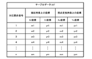
- FIG. 7 shows an example of the table data 107.
- the table data 107 is a coordinate correspondence table that defines a correspondence relationship between the coordinates of discrete pixels of the captured image 502 and the coordinates of pixels of the viewpoint conversion image 503 corresponding to the coordinates.
- coordinate correspondence information of each pixel indicated by “correspondence relation number” is shown.
- the image processing apparatus 10 refers to the table data 107 for each pixel coordinate of the captured image 502 to calculate the corresponding pixel coordinate of the viewpoint conversion image 503.
- FIG. 8 is a table 107a in which correction target coordinate corresponding points are extracted from the table data 107 and the coordinates before and after correction are shown.
- the table 107a the three-dimensional object distance necessary for correcting the table data 107 is also shown.
- the table 107a shown in FIG. 8 is merely illustrated for explanation, and need not be stored in the RAM 13 or the storage unit 14.
- the table correction unit 103 corrects the table data 107 by correcting the coordinate correspondence information related to the correction target coordinate corresponding point among the coordinate corresponding information related to each coordinate corresponding point of the table data 107.
- the correction target coordinate corresponding points o1, o2, o3,..., Oi are coordinates on these viewpoint conversion images, that is, coordinates in the virtual viewpoint coordinate system V, (xv_o1, yv_o1), ( xv_o2, yv_o2), (xv_o3, yv_o3), ..., (xv_oi, yv_oi), (xv_o1 ', yv_o1'), (xv_o2 ', yv_o2'), (xv_o3 ', yv_o3'), Corrections are made to (xv_oi ′, yv_oi ′), respectively. As described above, the table correction unit 103 performs correction using the three-dimensional object distance.
- FIG. 9 (1) shows a captured image 505 of the front camera 20a.
- FIG. 9B is a diagram showing a distance image 506 acquired by the distance detection unit 30, and
- FIG. 9C is a diagram showing a distance image 507 acquired by an ideal distance detection unit.
- the distance is represented by shading.
- the captured image 505 includes a three-dimensional object 51 located on the left hand and white lines LL and LR extending upward from below the center.
- the marker 52 is at the lower part of FIG. 9 (1), and the horizon 54 is at the upper part of FIG.
- a distance image 507 shown in FIG. 9 (3) is obtained.
- the entire shape of the three-dimensional object 51 is measured as indicated by reference numeral 511.
- FIG. 10A is an enlarged view of the vicinity of the reference numeral 510 in FIG. 9B and the outline of the three-dimensional object 51 is superimposed.
- FIG. 10 (2) is a diagram showing the boundaries of the measurement range in FIG. 10 (1).
- FIG. 10 (3) is a diagram in which coordinates corresponding pixels of the table data 107 are superimposed on the diagram of FIG. 10 (2).
- the coordinate corresponding pixels in FIG. 10 (3) are indicated by three types of cross marks ( ⁇ ), circle marks ( ⁇ ), and triangle marks ( ⁇ ).
- the cross mark indicates a point where distance information is obtained.
- a circle indicates a point corresponding to the three-dimensional object 51 and a point for which distance information is not obtained.
- the triangle mark indicates a point corresponding to the ground and the distance information is not obtained.
- the circle indicated by reference numeral 512 is a part of the three-dimensional object 51, it should be recognized at substantially the same distance as other parts of the three-dimensional object 51. Since the point indicated by the triangle indicated by reference numeral 513 is included in the ground, it should be recognized at substantially the same distance as the ground portion indicated by reference numeral 55.
- the distance correction unit 102 corrects the distance information as shown in FIG. That is, the distance correction unit 102 calculates the three-dimensional object distance shown in FIG.
- the table correction unit 103 corrects the table data 107 using the calculated three-dimensional object distance. As a result, appropriate conversion is performed on all coordinate-corresponding pixels in the table data 107.
- the image recognition unit 101 divides the photographed image into a plurality of regions, that is, segments by the segmentation process using the method using the color information described above with the photographed image 505 of the camera 20a shown in FIG. To do.
- the three-dimensional object 51 is recognized as one area indicated by reference numeral 601 and the marker 52 is recognized as four areas as indicated by reference numeral 603.
- Reference numerals 602 and 604 correspond to white road lines.
- Reference numeral 600 corresponds to the horizon.
- FIG. 11 (2) is a diagram in which symbols are attached to the respective segments shown in FIG. 11 (1) for convenience. As shown in FIG. 11 (2), the captured image is divided into nine segments SG11 to SG19 by the image recognition unit 101. However, in this segment division, it is not distinguished whether each segment is a three-dimensional object or a road surface.
- the distance correcting unit 102 corrects the distance of the coordinate corresponding point in the segment for each segment by any one of the following three methods.
- the first method is a simple average.
- the distance correction unit 102 calculates the average value of the distance information of all the coordinate corresponding points in the segment, and sets this average value as the three-dimensional object distance of all the coordinate corresponding points in the processing target segment. That is, according to the first method, all coordinate corresponding points in the segment have the same three-dimensional object distance.
- Circle mark 512 gives ⁇ dn / n which is an average value of distance information.
- the second method is a first order approximation.
- the distance correction unit 102 approximates the correlation between each coordinate value and distance information with a linear function for the coordinate corresponding points in the segment.
- the distance correction unit 102 determines the three-dimensional object distance of each coordinate corresponding point based on the approximate expression. That is, according to the second method, for example, the distance of the wall that faces the vehicle 1 diagonally can be accurately calculated.
- the least square method is used for the distance information dn (n is the number of cross marks included in the solid object 51) corresponding to the solid object 51 among the cross marks in FIG.
- the distance information of the circle 512 in FIG. 10 (3) is also obtained after using f (x, y). It becomes.
- the third method is multidimensional approximation.
- the approximation in the second method is a second-order or higher-order multidimensional function. According to the third method, the distance of an object having a complicated shape can also be accurately calculated.
- the coordinates of the point Pw1 indicating the distance information corresponding to the point Pr in the captured image 502 are as follows. Can be asking.
- xw1 d ⁇ cos ⁇ e ⁇ sin ⁇ a + xs
- yw1 d ⁇ cos ⁇ e ⁇ cos ⁇ a + ys
- zw1 R ⁇ sin ⁇ e + zs.
- the affine transformations shown in Equations 1 and 3 can be expressed as Equations 6 and 7 using the coordinate values shown in FIG.
- Equation 8 an equation for coordinate-converting the point Pr of the captured image 502 to the point of the viewpoint conversion image 503 is obtained.
- the point Pr in the captured image 502 is corrected from the point Pv to the point Pv1 in the viewpoint conversion image 503.
- the operation of the image processing apparatus 10 when the viewpoint conversion image is displayed on the user interface unit 40 will be described.
- the operation of the image processing apparatus 10 described below is executed every predetermined time.
- the execution subject of each step described below is the CPU 11.
- the step diagram shown in FIG. 12 is an example, and the order of S11 and S12 may be reversed if the processing described below can be realized.
- the CPU 11 acquires a distance image from the distance detection unit 30 (S11).
- the CPU 11 acquires a captured image from the camera 20 (S12).
- the CPU 11 causes the image recognition unit 101 to process the distance image acquired in step S12 to execute segment division (S13).
- the example of step S13 is as described in FIG.
- the CPU 11 sequentially executes steps S15 to S18 described below for each segment calculated in step S13 (S14).
- the processing of S15 to S18 may be executed in parallel for all segments.
- an example will be described in which the processing target is changed and the segments are processed in order one by one.
- a segment to be processed is called a process target segment.
- the CPU 11 determines whether the processing target segment is a region corresponding to a three-dimensional object or a region corresponding to a road surface based on the distance information in the processing target segment (S15).
- Judgment whether the processing target segment is a three-dimensional object can be performed as follows, for example. That is, since the mounting position and mounting posture of the camera 20 are known, the associating unit 104 can calculate the relationship between the position in the captured image and the distance in advance by assuming that the imaging target is a road surface. Therefore, by comparing the difference between the distance information in the segment and the above-described distance calculated from the position in the captured image of the segment, it can be determined whether or not the subject in the segment is a road surface.
- the CPU 11 proceeds to step S16 when determining that the subject in the processing target segment is a three-dimensional object, and proceeds to step S18 when determining that the subject in the segment is a road surface. If it is determined that the distance is infinite or cannot be measured, and if it is determined that the subject of the processing target segment is empty, the process proceeds to step S18.
- step S16 the CPU 11 corrects the distance information of all coordinate corresponding points in the processing target segment using the distance correction unit 102. That is, the CPU 11 calculates a three-dimensional object distance.
- the CPU 11 causes the table correction unit 103 to rewrite all coordinate corresponding points in the processing target segment in the table data 107 (S17), and then proceeds to step S19.
- step S17 the table data 107 corrected in step S17 is discarded after execution of step S19 described later is completed. That is, the process of step S17 is correction for temporary copying of the table data 107.
- step S18 is executed. In this case, the CPU 11 proceeds to step S19 without causing the table correction unit 103 to correct the table data 107. That is, since no special process is performed in step S18, if it is determined that the road surface is in step S15 (S15: NO), the process may proceed to step S19 as it is.
- step S18 the CPU 11 determines whether all segments have been processed. When determining that there is an unprocessed segment, the CPU 11 sets the segment as a processing target and returns to step S15. If the CPU 11 determines that all segments have been processed, the process proceeds to step S19.
- step S19 the CPU 11 converts the photographed image of the camera 20 into a viewpoint converted image viewed from the virtual viewpoint 53 by using the table data 107 corrected by the image conversion unit 105 in step S17.
- step S19 the user interface control unit 106 outputs the viewpoint conversion image to the user interface unit 40, and the process ends.
- the image processing apparatus 10 includes a camera 20 that acquires a captured image, a distance detection unit 30 that acquires a distance image, and image recognition that extracts a region including a three-dimensional object region corresponding to the three-dimensional object in the captured image.
- Unit 101 distance correction unit 102 that calculates depth information of a three-dimensional object region based on a distance image, and three-dimensional object region calculated by distance correction unit 102 that is table data 107 that is coordinate conversion information for performing coordinate conversion of a captured image
- a table correction unit 103 that corrects the image based on the depth information
- an image conversion unit 105 that generates a viewpoint conversion image obtained by coordinate-converting the captured image using the table data 107 corrected by the table correction unit 103. Therefore, according to the present embodiment, the viewpoint conversion image can be obtained by processing the three-dimensional object region in the planar image three-dimensionally using the value of the distance image.
- the distance image acquisition range A30 in which the distance detection unit 30 acquires a distance image is smaller than the plane image acquisition range A20 in which the camera 20 acquires a plane image, and the plane image acquisition. It is set to overlap a part of the range A20. Therefore, according to the image processing apparatus 10 of the present embodiment, even when a distance image having a narrow measurement range compared to the camera 20 is used, a highly accurate viewpoint conversion image for a wide range of three-dimensional objects exceeding the measurement range of the distance image. Can be generated.
- the image recognition unit 101 extracts outlines of a plurality of segments including a three-dimensional object region based on at least one of brightness, brightness, saturation, and brightness of a captured image. Therefore, the image recognition unit 101 can easily divide the captured image into a plurality of segments including the three-dimensional object region.
- the table data 107 includes a plurality of combinations of conversion source coordinates on the captured image and conversion destination coordinates on the viewpoint conversion image. Based on the distance information of the three-dimensional object region in the distance image, the table correction unit 103 corrects the conversion destination coordinates, that is, the coordinates on the viewpoint conversion image, as shown in FIG. Thereby, in this embodiment, distance information can be given even outside the measurement range in which no distance image is acquired.
- the table data 107 is created in advance on the assumption that the subject in the captured image is an area on the road surface.
- the image recognition unit 101 divides the captured image into a plurality of segments for each subject included in the captured image.
- the table correction unit 103 determines whether or not the plurality of segments are solid object areas based on the distance image (S15 in FIG. 12), and corresponds to the conversion source coordinates in the segments determined to be solid object areas.
- the conversion destination coordinates are corrected in the table data 107 (S17).
- the table data 107 is calculated on the assumption that the subject of the photographed image exists within the reference height plane.
- the table correction unit 103 calculates the height of the subject from the reference height plane 501 and the position of the subject on the reference height plane using the depth information of the three-dimensional object region calculated by the distance correction unit 102. Further, the table correction unit 103 corrects the table data 107 using the viewpoint conversion reference position, the calculated height of the subject from the reference height plane, and the calculated position of the subject on the reference height plane.
- the table data 107 in the first embodiment indicates a correspondence relationship between the point Pr on the captured image and the point Pv on the viewpoint conversion image represented by the above-described Expression 5.
- table data 107 may indicate the correspondence between the point Pr on the photographed image represented by Equation 1 and the point Pw on the three-dimensional space.
- table data 107b it will be referred to as table data 107b below.
- the captured image projected on the three-dimensional section is deformed by correcting the table data 107b.
- the image conversion unit 105 creates an image obtained by capturing a captured image projected on the three-dimensional space from a virtual viewpoint, that is, a viewpoint converted image.
- FIG. 13 shows an example of the table data 107b.
- the table data 107b indicates the correspondence between the point Pr on the photographed image 502 expressed by Equation 1 and the point Pw in the three-dimensional space.
- a viewpoint conversion image can be created using the table data 107b even when a virtual viewpoint that is not assumed in advance is set by the user.
- the table data 107 of the first embodiment was created in advance under the assumption that all subjects are on the road surface. However, the table data 107 may be created at any time without being created in advance. In this case, table data 107 is created in the process shown in FIG. That is, in step S17, a corresponding portion of the table data 107 is created. By creating the table data 107 as needed, the amount of storage area used can be reduced.
- the vehicle 1 includes four cameras: a front camera 20a, a left camera 20b, a right camera 20c, and a rear camera 20d. However, the vehicle 1 may be provided with at least one camera. The vehicle 1 may include five or more cameras.
- the image recognition unit 101 divides a captured image into a plurality of regions by performing segment division processing.
- the table correction unit 103 corrects the table data 107 using the coordinate corresponding point of the region corresponding to the three-dimensional object as a processing target.
- the image recognition unit 101 may specify only the area corresponding to the three-dimensional object in the captured image. For example, by extracting a part of the depth image where the depth information does not change stepwise, and specifying the area of the same subject corresponding to that part in the photographed image, the area corresponding to the three-dimensional object is identified in the photographed image. Is possible.
- the table data 107 is created in advance under the assumption that all subjects are present on the road surface.
- the table data 107 may be created in advance under the assumption that it exists along a certain three-dimensional shape.
- the table data 107 may be created by setting a sphere with the vehicle center as the origin.
- the above components, functions, and the like may be realized by software by interpreting and executing a program that realizes each function by the processor.
- Information such as programs, tables, and files for realizing each function can be stored in a memory, a recording device such as a hard disk or SSD, or a recording medium such as an IC card, SD card, or DVD.
- control lines and information lines indicate what is considered necessary for the explanation, and not all control lines and information lines on the product are necessarily shown. Actually, it may be considered that almost all the components are connected to each other.
Landscapes
- Engineering & Computer Science (AREA)
- Multimedia (AREA)
- Physics & Mathematics (AREA)
- General Physics & Mathematics (AREA)
- Theoretical Computer Science (AREA)
- Mechanical Engineering (AREA)
- Computer Vision & Pattern Recognition (AREA)
- Signal Processing (AREA)
- Image Processing (AREA)
- Closed-Circuit Television Systems (AREA)
- Traffic Control Systems (AREA)
- Image Analysis (AREA)
Abstract
より精度の高い視点変換画像を得ることができるようにした画像処理装置および方法を提供すること。 画像処理装置10は、平面画像を取得する平面画像取得部20と、奥行き情報を有する距離画像を取得する距離画像取得部30と、平面画像から立体物の範囲に相当する立体物領域Ob1,Ob2を抽出する画像認識部と、立体物領域の奥行き情報を距離画像に基づいて算出する距離修正部と、平面画像を所定の視点から見える視点変換画像に座標変換する座標変換情報を、算出された立体物領域の奥行き情報に基づいて補正するテーブル補正部と、補正された座標変換情報を用いて平面画像を座標変換することにより、視点変換画像PG1,PG2を生成する画像変換部と、を備える。
Description
本発明は、画像処理装置および方法に関する。
車両に設置されたカメラで車両の周囲を撮影し、撮影された画像を変形合成して視点変換画像を生成し、車内に表示する画像表示システムが知られている。このような画像表示システムを利用することにより、運転者は、車両周辺の様子を視認性高く確認することができる。
特許文献1には、第1射影変換を用いて撮影画像から周辺俯瞰画像を生成する周辺俯瞰画像生成部と、車載カメラの視野内に存在する立体物を検知して、当該立体物の位置を含む立体物情報を出力する立体物検知部と、立体物情報に基づいて撮影画像から立体物が写っている画像領域である立体物画像を抽出する立体物抽出部と、周辺俯瞰画像における立体物の歪みを低減する第2射影変換を用いて立体物画像から立体物俯瞰画像を生成する立体物俯瞰画像生成部と、立体物情報に基づき周辺俯瞰画像に立体物俯瞰画像を画像合成する画像合成部を備えた画像生成装置が開示されている。
特許文献1に記載の発明では、カメラと立体物を検出するモジュールとで測定する範囲が異なる場合、視点変換画像において立体物の形状に歪みが発生する。距離センサを併用することにより立体形状を再現する手法も考えられるが、歪みの少ない視点変換画像を生成することは困難である。
本発明は上記の課題に鑑みてなされたもので、その目的は、より精度の高い視点変換画像を得ることができるようにした画像処理装置および方法を提供することにある。
上記課題を解決すべく、本発明の一つの観点に従う画像処理装置は、平面画像取得部から取得する平面画像から立体物の範囲に相当する立体物領域を抽出する画像認識部と、前記立体物領域の奥行き情報を、距離画像取得部から取得する奥行き情報を有する距離画像に基づいて算出する距離修正部と、前記平面画像中の一部領域に該当する奥行き情報を前記距離画像中の一部領域から特定する対応付け部と、前記平面画像を所定の視点から見える視点変換画像に座標変換する座標変換情報を、前記算出された前記立体物領域の奥行き情報に基づいて補正するテーブル補正部と、前記補正された座標変換情報を用いて前記平面画像を座標変換することにより、前記視点変換画像を生成する画像変換部と、を備える。
本発明によれば、平面画像から抽出される立体物領域の奥行き情報を距離画像に基づいて算出し、算出された奥行き情報に基づいて座標変換情報を補正することができるため、歪みの発生を抑制した視点変換画像を得ることができる。
以下、図面に基づいて、本発明の実施の形態を説明する。本実施形態に係る画像処理装置は、例えば、乗用車、バス、トラックなどの自動車、ホイールローダや油圧ショベルなどの建設機械、鉄道車両、飛行ロボット(いわゆるドローン)、人型ロボットなどに用いることができる。さらに、本実施形態に係る画像処理装置は、例えば、住宅、商業施設、工場、倉庫などの建築物の周辺を監視するセキュリティシステムにも適用することができる。以下の説明では、自動車に適用する場合を例に挙げるが、本実施形態は上述のように、自動車以外の製品にも適用可能である。
図1~図12を用いて第1実施例を説明する。図1は、車両1に搭載される画像処理装置10のハードウェア構成と画像処理の概要とを示す説明図である。
車両1は、例えば、車体、駆動機構、制御機構などを有する。本実施例に係る画像処理装置10は、制御機構の一部として車両1に搭載される。
車両1は、例えば、画像処理装置10と、車両1の前方に設けられる前カメラ20aと、車両1の左側面に設けられる左カメラ20bと、車両1の右側面に設けられる右カメラ20cと、車両1の後方に設けられる後カメラ20dと、距離検出部30と、ユーザインターフェース部(UI部)40とを備える。距離検出部30は、例えば、車両1の前後方および側方の物体を検出できるように、車両1の前後の四隅に配置される。
以下、前カメラ20aと左カメラ20bと右カメラ20cと後カメラ20dとを区別しない場合、カメラ20と呼ぶ。カメラ20は、「画像取得部」の例である。カメラ20は、例えば、CCD(Charge Coupled Device)カメラまたはCMOS(Complementary Metal Oxide Semiconductor)カメラなどの主に可視域を検出する撮像素子と、撮像素子で検出した信号を記録する画像メモリと、検出信号を増幅等する処理回路(いずれも不図示)とを含むことができる。車両1は、さらに、赤外線を検出可能な撮像素子を有するカメラを搭載することもできる。画像処理装置10は、赤外線カメラからの信号を取り込んで画像として処理してもよい。
カメラ20により撮影して得られた画像を撮影画像と呼ぶ。撮影画像は「平面画像」の例である。撮影画像の解像度は、例えばカメラ20に内蔵される撮像素子の数により決定される。カメラ20は、例えば1920×1080の解像度を有する。以下、解像度を空間解像度とも呼ぶ。
カメラの撮影範囲は、例えば、カメラ20に内蔵される撮像素子の大きさとレンズの焦点距離とにより決定される。本実施例では、例えば水平方向に180度の角度で撮影可能であるとする。以下、撮影可能な角度を測定範囲とも呼ぶ。
カメラ20と距離検出部30とは同期して動作しており、同一タイミングで周囲の情報を取得する。画像処理装置10は、カメラ20の撮影画像を用いて、仮想視点53(図5参照)から車両1の周囲を見渡した場合の画像(以下、視点変換画像)を生成する。仮想視点53は、カメラ20の設置位置とは異なる場所(例えば、車両1の上方など)に設定される。
画像処理装置10の生成した視点変換画像は、ユーザインターフェース部40に送られて表示される。ユーザ(ドライバ)は、ユーザインターフェース部40に表示された視点変換画像を見ることにより、車両1の周囲の状況を一目で把握することができる。
カメラ20の車両1への取付位置、および取付姿勢は既知であり、記憶部14に格納されている。
「距離画像取得部」の例である距離検出部30は、車両1の周囲の物体の奥行き情報を、水平方向および垂直方向に(すなわち2次元に)分解能を持った情報として検出する装置である。距離検出部30は、例えば、LiDAR(Light Detection and Ranging)である。LiDAR以外に距離情報を測定可能な装置を用いてもよい。以下、距離検出部30が取得する2次元に分解能を有する距離情報を「距離画像」と呼ぶ。
距離検出部30の測定範囲は、カメラ20の撮影範囲の少なくとも一部と重複する。ただし距離検出部30が取得する距離画像の測定範囲(距離画像取得範囲)は、カメラ20の測定範囲(平面画像取得範囲)よりも狭い。例えば、カメラ20は水平方向x垂直方向が180度x160度の測定範囲を有するのに対して、距離検出部30は120度x120の測定範囲を有する。すなわちカメラ20の測定範囲を第1の測定範囲、距離検出部30の測定範囲を第2の測定範囲と呼ぶと、第2の測定範囲は第1の測定範囲よりも低い。距離検出部30の車両1への取付位置および取付姿勢は既知であり、記憶部14に格納される。
ユーザインターフェース部40は、ユーザとの間で情報を交換する装置である。ユーザインターフェース部40は、ユーザが画像処理装置10へ指示する情報入力部と、画像処理装置10がユーザへ情報を提供する情報出力部とを有することができる。
情報入力部としては、例えば、タッチパネル、キーボード、音声入力装置、手動スイッチ、ブレイン・マシン・インターフェース(Brain-machine Interface:BMI)などを用いることができる。情報出力部としては、例えば、LCD(Liquid Crystal Display)ディスプレイ、プロジェクタ、車両1に搭載されたカーナビゲーション装置の表示部、ヘッドマウントディスプレイなどを用いることができる。
ユーザインターフェース部40は、画像処理装置10と有線または無線で接続されることができる。ユーザインターフェース部40が無線で画像処理装置10と接続される場合には、携帯電話(いわゆるスマートフォンを含む)、ノート型またはタブレット型、ブレスレット型、眼鏡型などの携帯情報端末をユーザインターフェース部40として用いることもできる。
画像処理装置10は、例えば、マイクロプロセッサ(CPU:Central Processing Unit)11、ROM(Read Only Memory)12、RAM(Random access memory)13、記憶部14、通信インターフェース15、ユーザインターフェース(UI-IF)16を備えることができる。図示は省略するが、GPU(Graphics Processing Unit)、特定の処理に特化した専用回路、FPGA(Field-Programmable Gate Array)などを備えてもよい。
ROM12には、後述の画像処理動作を実行するコンピュータプログラムなどが記憶されている。記憶部14は、例えば、フラッシュメモリデバイスやハードディスクドライブのように、不揮発性の記憶装置として構成される。記憶部14には、画像変換に使用するテーブルや、カメラ20の取付位置および角度、距離検出部30の取付位置および角度などが記憶されている。
通信インターフェース15は、画像処理装置10と他の装置が情報を交換するための出入り口である。カメラ20および距離検出部30からのデータは、通信インターフェース15を介して、画像処理装置10へ入力される。通信インターフェース15は、例えば、シリアルポートとして構成してもよいし、A/D(Analog / Digital)コンバータなどを含んでもよい。
図1の下側に画像処理装置10による画像処理の概要を示す。車両1の前方に、例えば信号機や樹木などのオブジェクト(三次元対象物)Ob1,Ob2が存在するものとして説明する。
画像処理装置10は、カメラ20から平面画像(撮影画像)21を取得するとともに(S1)、距離検出部30から距離画像31を取得する(S2)。画像処理装置10は、平面画像から立体物であるオブジェクトOb1,Ob2の範囲に相当するセグメントSG1,SG2を抽出する(S3)。平面画像21を複数のセグメントに分割する場合、立体的なオブジェクトOb1,Ob2以外の部分もセグメントとして分割されるが、図1ではその過程を省略して示す。
画像処理装置10は、「立体物領域」としてのセグメントSG1,SG2と距離画像31とを比較することにより、距離画像31のうちセグメントSG1,SG2に対応する領域の距離を求める(S4)。
画像処理装置10は、セグメントSG1,SG2内の未知の距離を、距離画像31の対応部分から得られる既知の距離に基づいて補正(補間)する(S5)。
最後に、画像処理装置10は、平面画像21を仮想視点53から見た場合の視点変換画像に変換する(S6)。オブジェクトOb1,Ob2の輪郭を示すセグメントSG1,SG2は、所定の曲面上に広がるオブジェクトPG1,PG2に変換されて、ユーザインターフェース部40に表示される。
図1では、1つの平面画像から視点変換画像を生成するかのように説明したが、実際には、前後左右の各カメラ20a~20dで撮影した平面画像のそれぞれについて、距離を検知できなかった領域の距離情報を補正し、補正後の各平面画像を合成して変換することにより視点変換画像を得る。以下、さらに詳細に説明する。
図2(1)は、カメラ20により撮影される測定範囲A20の概念図である。図2(2)は、理想的な距離検出部30rの測定範囲A30rの概念図である。測定範囲A30rは、カメラ20の測定範囲A20と比較して十分に広い。十分に広い測定範囲を持つ距離検出部30rは、説明のために示しており、実際の車両1には搭載されない。図2(3)は、実際に車両1に搭載されている距離検出部30の測定範囲A30の概念図である。測定範囲A30は、カメラ20の測定範囲A20と比較して狭い。
図2(4)は、カメラ20の測定範囲A20と理想的な距離検出部30rの測定範囲A30rとを比較する平面図である。同様に、図2(5)は、カメラ20の測定範囲A20と実際の距離検出部30の測定範囲A30とを比較する平面図である。図2では、視認性向上のために、図2(1)のカメラ20と図2(5)の測定範囲A20とを結ぶ線を省略している。
図2(1)~(3)は、カメラ20もしくは距離検出部30を水平方向に向けて設置したときの測定範囲を上面図として示した例である。図中のθx_cam、θx_range1、θx_range2はそれぞれ、カメラ20もしくは距離検出部30の水平方向の測定範囲を示す。
ここで、図2(4),(5)では、カメラ20の水平方向の測定範囲は、いずれもθx_camである。しかし、図2(4)では、カメラ20の測定範囲A20よりも理想的な距離検出部30rの測定範囲A30rの方が十分に広い。これに対し、図2(5)では、実際の距離検出部30の測定範囲A30は、カメラ20の測定範囲A20よりも小さい。このため、図2(5)では、カメラ20の測定範囲A20の一部が距離検出部30で網羅できていない。つまり、距離検出部30は、カメラ20の測定範囲A20のうち一部の距離情報のみ取得することができ、残りの部分については距離情報を取得できない。
図2(5)の場合、カメラ20で撮影される立体物の一部は、距離検出部30により距離画像を取得することができないため、その立体形状を検出することができない。本実施例では、カメラ20と比較して測定範囲の狭い距離検出部30を使用するが、後述する手法により、図2(2)に示す測定範囲の広い距離検出部30rを使用する場合と近い結果を得ることができる。
図3は、画像処理装置10の有する機能を示す機能ブロック図である。画像処理装置10は、その機能として、例えば、画像認識部101と、距離修正部102と、テーブル補正部103と、対応付け部104と、画像変換部105と、ユーザインターフェース制御部106とを備える。
「座標変換情報」の例であるテーブルデータ107は、記憶部14に格納される情報である。テーブルデータ107は、俯瞰画像や鳥瞰画像などの視点変換画像を生成する際に用いられるルックアップテーブルである。テーブルデータ107は、画像処理装置10を含むシステムの設計段階において、車両1に設置するカメラ20の位置および角度と、仮想視点53の位置および角度と、撮像条件とにより予め作成される。テーブルデータ107は、カメラ20のそれぞれについて視点変換を行う仮想視点ごとに存在する。以下では、主に一つのカメラ(例えば前カメラ20a)についての、或る1つの仮想視点53を例に挙げて説明する。
画像認識部101は、カメラ20の撮影した画像(平面画像)を処理対象とし、撮影画像に含まれる被写体ごとの輪郭(立体物領域)を抽出して、撮影画像を複数の領域に分割するセグメント分割処理を行う。
以下の説明では、画像認識部101が行うセグメント分割処理によって撮影画像内に設定される各領域を「セグメント」と称する。本処理における被写体の輪郭抽出は、既知の輪郭検出法に基づいてもよい。あるいは、撮影画像の色情報を解析し、輝度、色相、彩度、および明度の類似性から撮影画像を複数の領域に分割して各領域の輪郭を抽出する方法を採用することもできる。
距離画像認識部108は、距離検出部30の検出した距離画像を処理対象とし、距離画像から距離情報の変化を抽出することにより、距離画像を複数の領域に分割するセグメント分割処理を行う。以下の説明では、距離画像認識部108が行うセグメント分割処理によって距離画像内に設定される各領域を「距離画像セグメント」と称する。距離画像セグメントの分割方法としては、例えば、距離情報から得られる3次元情報を解析して平面、立体形状を推測し、形状から各領域を抽出する方法を採用することができる。
距離修正部102は、画像認識部101の認識結果に含まれる立体物に対応するセグメント、すなわち被写体が立体物である領域が存在する場合に、当該セグメントについて、距離を補正する。距離修正部102は、後述するそれぞれの座標対応点を対象として、距離検出部30の測定値である距離を補正する。距離修正部102により補正された距離を、以後は「立体物距離」と呼ぶ。
テーブル補正部103は、距離修正部102が算出した立体物距離を用いて、テーブルデータ107を書き換える。
対応付け部104は、カメラ20および距離検出部30の、それぞれの車両1への取付位置および取付姿勢に基づいて、撮影画像と距離画像とを対応付ける。例えば、対応付け部104は、撮影画像上の或る領域に対応する距離画像上の領域を算出し、あるいは、距離画像上の或る領域に対応する撮影画像上の領域を算出する。
画像変換部105は、テーブル補正部103により書き換えられたテーブルデータ107を用いてカメラ20の撮影画像を変換することにより、カメラ20の撮影画像を組み合わせて仮想視点53における視点変換画像を生成する。
ユーザインターフェース制御部106は、画像変換部105により生成された視点変換画像をユーザインターフェース部40に出力して表示させる。
(動作環境)
図4および図5は、画像処理装置10の動作環境を説明する。図4は、画像処理装置10を搭載する車両1を上部から見下ろした図である。図5は、車両1を側面から見た図である。
車両1は、車両通行帯を示す白線である直線LL,LRに挟まれた領域に存在する。車両1の前方正面の地面にはマーカ52が設置されている。車両1の前方左には、樹木のような立体物51がある。
車両1の前部には前カメラ20aが設置されている。前カメラ20aの光軸は、車両1の前方の路面に向けられており、立体物51およびマーカ52をその撮影範囲内に捉えている。
同様に、車両1の左部、右部および後部には、それぞれ左カメラ20b、右カメラ20c、および後カメラ20dが設置されている。各カメラ20b,20c,20dの光軸は、それぞれ車両1の左方、右方、後方の路面に向けられている。
本実施例のカメラ20は、広角レンズを備えており、約180度の画角を有する。カメラ20および距離検出部30の、設置位置および設置角度は、車両1の設計段階において予め定められており、既知である。その値は記憶部14に格納されている。
図5に示す仮想視点53は、車両1の前方上部から真下を撮像することにより、車両1の前方を俯瞰する視点である。以下、図5に示す状況において、仮想視点53から得られる画像の作成方法を説明する。図1でも述べたように、画像処理装置10は車両1の前後左右にそれぞれカメラ20a~20dを備えるが、ここでは、主に前カメラ20aの撮影画像を変換する場合を代表して説明する。
(座標変換)
図6は、カメラ座標系、仮想視点座標系、およびワールド座標系の定義を示す説明図である。
カメラ座標系とは、画像を撮影するカメラ20を基準とする座標系である。図6には、前カメラ20aを基準とするカメラ座標系Rの3軸、すなわちXr,Yr,Zrが示されている。
仮想視点座標系とは、予め定められた仮想視点53を基準とする座標系である。図6には、仮想視点53を基準とする仮想視点座標系Vの3軸、すなわちXv,Yv,Zvが示されている。
ワールド座標系とは、車両1が走行する路面を基準に設定された座標系である。図6には、ワールド座標系Wの3軸、すなわちXw,Yw,Zwが示されている。XwおよびYwは路面に平行であり、Zw=0の基準高さ平面501に路面が含まれる。
カメラ座標系Rの1つの軸Zrは、前カメラ20aの光軸と一致しており、すなわち撮像素子と直交する。他の軸Xrおよび軸Yrは、前カメラ20aの撮像素子の長辺および短辺と平行である。カメラの焦点距離zrを用いて表すと、撮影画像502を構成する各画素の位置は、Zr=zrに位置するXrYr平面上の座標データで表現される。すなわち、カメラ座標系Rは、撮影画像502の座標系と等しい。
仮想視点座標系の軸Zvは、仮想視点53に置かれた仮想的なカメラの光軸と一致しており、すなわち仮想的な撮像素子と直交する。他の軸Xvおよび軸Yvは、仮想的な撮像素子の長辺および短辺と平行である。仮想視点53に置かれるカメラの焦点距離zvを用いて表すと、視点変換画像503を構成する各画素の位置は、Zv=zvに位置するXvYv平面上の座標データで表現される。すなわち、仮想視点座標系Vは、視点変換画像503の座標系と等しい。
ここで、或る点Pをワールド座標系Wでは点Pwと呼び、その座標を(xw、yw、zw)と表す。前カメラ20aにより点Pwを撮影した際の撮影画像における点を点Prと呼び、点Prの座標を(xr、yr、zr)と表す。仮想視点53から得られる画像における点を点Pvと呼び、Pvの座標を(xv、yv、zv)と表す。
ワールド座標系Wにおける点Pwの座標(xw、yw、zw)をカメラ座標系Rの点Prの座標(xr、yr、zr)に座標変換するには、例えば、数1に示すようなアフィン変換が用いられる。

ここで、Mrは、数2に示されるような4×4の透視投影変換行列である。

数2において、Rrは3×3の回転行列、Trは1×3の平行移動行列、0は3×1の零行列である。回転行列Rrおよび平行移動行列Trは、ワールド座標系上でのカメラ20aの設置位置および設置角度、カメラ20aの内部パラメータである焦点距離および撮像素子の有効画素サイズなどに基づいて、周知な方法で算出される。
ワールド座標系Wの点Pwの座標(xw、yw、zw)を仮想視点座標系Vの点Pvの座標(xv、yv、zv)に座標変換するには、例えば、数3に示すようなアフィン変換が用いられる。
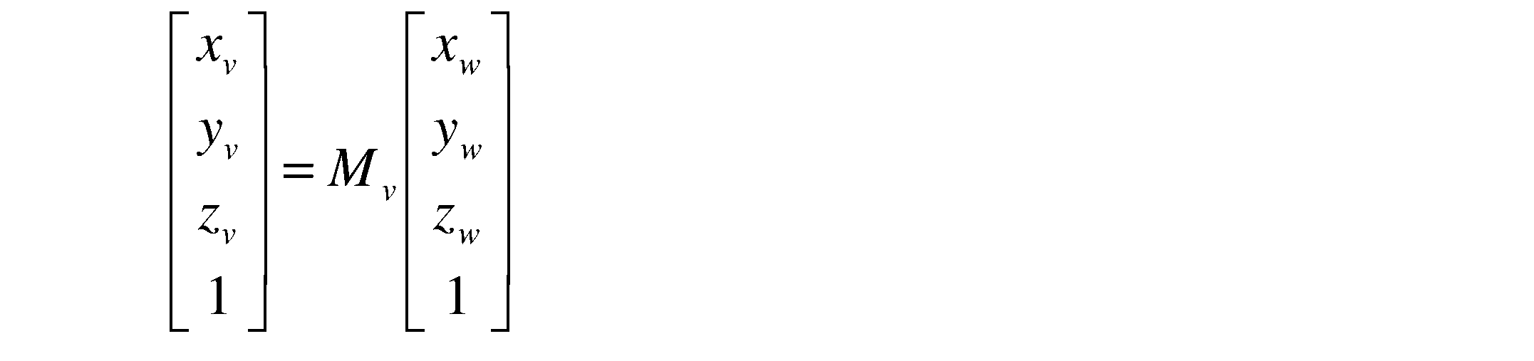
ここで、Mvは、数4に示されるような4×4の透視投影変換行列である。

数4において、Rvは3×3の回転行列、Tvは1×3の平行移動行列、0は3×1の零行列である。回転行列Rvおよび平行移動行列Tvは、ワールド座標系上での仮想視点53の位置および角度、仮想視点53の仮想的な焦点距離および撮像素子の有効画素サイズなどに基づいて周知な方法で算出される。
上述した数1と数3とを組み合わせると、カメラ座標系Rの点Prの座標を仮想視点座標系Vの点Pvの座標に座標変換するための式(数5)が得られる。

数5では、透視投影変換行列Mrの逆行列によりカメラ座標系Rの点Prの座標をワールド座標系の点Pwの座標に座標変換し、その点Pwの座標を透視投影変換行列Mvにより仮想視点座標系Vの点Pvの座標(xv,yv,zv)に座標変換している。数5による座標変換結果を用いて、視点変換画像503の点Pvの画素値を、対応する撮影画像502の点Prの画素値から算出することができる。
ただしカメラ20の撮影画像からは、被写体までの距離情報が得られないので、例えば点Pwが路面上、すなわちzw=0の平面上にあると仮定することで視点変換画像503の点Pvの画素値を算出することができる。そして路面上にない被写体が撮影された領域のみ視点変換画像503の点Pvの画素値を改めて計算する。
例えば撮影画像502における点Prが路面上の点Pwではなく、Zw=zw1(≠0)の平面上に存在する点Pw1であった場合は、視点変換画像503における対応点は点Pvではなく点Pv1となる。カメラ20の撮影画像の被写体が路面上に存在するか否かは、被写体までの距離により判断可能である。また被写体が路面上に存在しない場合は、その距離情報を用いることで視点変換画像503における対応点を算出可能である。
図6を参照して対応点の算出の例を説明する。まず画像処理装置10は、ワールド座標系におけるカメラ座標系Rの原点位置と、点Prの座標の幾何的な関係と、距離修正部102が算出した被写体までの距離情報とを用いて、被写体の基準高さ平面501からの高さ、すなわち点Pw1のZ座標であるzw1の値を算出する。
画像処理装置10は、点Pw1の基準高さ平面上の位置、すなわち点Pw1のX座標およびY座標を算出する。そして、画像処理装置10は、カメラ53の位置と、算出した点Pw1の位置から視点変換画像503における対応点Pv1の座標とを算出して、テーブルデータ107を補正する。
(テーブルデータ)
記憶部14に格納される各テーブルデータ107は、予め被写体がすべて路面上に存在するとの仮定の下で計算された、撮影画像上の点Prと視点変換画像上の点Pvとの対応関係を複数組について記述したものである。換言すると、テーブルデータ107は、被写体が基準高さ平面501内に存在することを前提に算出されている。
すなわち、カメラ座標系Rの所定の点Pr1の座標(xr1,yr1)、Pr2の座標(xr2,yr2)、・・・をそれぞれ上述の数5で仮想視点座標系Vの対応点への座標に変換して得られたものである。
ここで、2つの座標系で対応する点同士、すなわち画素同士の対応関係を座標対応情報と呼び、この座標対応情報がテーブルデータ107として作成されている。なお、テーブルデータ107においては、カメラ20aの焦点距離等が固定されているものとして、Zr座標の情報は省略されている。
以降の説明では、撮影画像502および視点変換画像503の画素のうち、テーブルデータ107に座標対応情報が記憶されている画素を座標対応画素、あるいは座標対応点と呼ぶ。すなわち、撮影画像502および視点変換画像503には、複数の座標対応点が予め設定されている。
テーブルデータ107を予め記憶部14に記憶しておき、視点変換画像503を作成する際に参照することで、上述した数5の演算回数を低減することができ、座標変換に要する処理時間を短縮することができる。
なお、テーブルデータ107に予め記憶しておく座標対応情報が増加するほど、テーブルデータ107のデータ量が増加する。そこで、テーブルデータ107のデータ量を削減するため、撮影画像502の一部の画素についてのみ座標対応情報を予め記憶し、他の画素については補間処理により点Pvの画素値を算出してもよい。テーブルデータ107は、カメラ20のレンズの歪みなどを考慮して作成されてもよい。
上述の通り、テーブルデータ107は、予め被写体がすべて路面上に存在するとの仮定の下で計算されている。そのため、被写体が路面上に存在しない場合、すなわち高さを有する立体物である場合は、距離情報に基づき計算を行いテーブルデータ107を書き換える必要がある。以下では、このテーブルデータ107の書き換えを、テーブルデータ107の補正とも呼ぶ。
本実施例では、テーブル補正部103がテーブルデータ107を補正する。すなわちテーブル補正部103は、テーブルデータ107における立体物51の領域に含まれる座標対応点を補正する。以下、補正対象の座標対応点を「補正対象座標対応点」と呼ぶ。
図7は、テーブルデータ107の一例を示す。テーブルデータ107は、撮影画像502の離散的な画素の座標と、その座標に対応する視点変換画像503の画素の座標との対応関係を定義する座標対応テーブルである。図7では、「対応関係番号」で示す各画素の座標対応情報が示されている。画像処理装置10は、撮影画像502の各画素の座標ごとにテーブルデータ107を参照することにより、対応する視点変換画像503の画素の座標を演算する。
図8は、テーブルデータ107から補正対象座標対応点を抽出し、補正前後の座標を示したテーブル107aである。テーブル107aでは、テーブルデータ107の補正に必要な立体物距離も併記している。図8に示すテーブル107aは、説明のために例示したにすぎず、RAM13や記憶部14に格納される必要はない。
本実施例では、テーブル補正部103がテーブルデータ107の各座標対応点に関する座標対応情報のうち、上記の補正対象座標対応点に関する座標対応情報を補正することで、テーブルデータ107を補正する。
具体的には、補正対象座標対応点o1、o2、o3、・・・、oiについて、これらの視点変換画像上の座標、すなわち仮想視点座標系Vにおける座標である、(xv_o1,yv_o1)、(xv_o2,yv_o2)、(xv_o3,yv_o3)、・・・、(xv_oi,yv_oi)を、(xv_o1’,yv_o1’)、(xv_o2’,yv_o2’)、(xv_o3’,yv_o3’)、・・・、(xv_oi’,yv_oi’)にそれぞれ補正する。前述の通り、テーブル補正部103は、立体物距離を用いて補正する。
仮に、カメラ20aの撮影画像の全領域に立体物が撮影されていた場合は、テーブルデータ107の全ての座標対応点について、視点変換画像上の座標が書き換えられることとなる。しかしこの場合でも、テーブルデータ107における撮影画像上の座標は書き換えられない。
(距離画像と補正の必要性)
図9(1)は、前カメラ20aの撮影画像505を示す。図9(2)は、距離検出部30が取得した距離画像506を示す図、図9(3)は理想的な距離検出部で取得した距離画像507を示す図である。図9(2),(3)では、距離を濃淡で表している。
図9(1)に示すように、撮影画像505には、左手に位置する立体物51と、中央の下から上へ延びる白線LL,LRとが含まれている。図9(1)の下部には、マーカ52があり、図9(1)の上部には地平線54がある。
図9(2)に示すように、距離検出部30が取得した距離画像506では、図2にて示したように撮影画像505のうちの一部が測定されている。立体物51は、符号510で示すようにその一部が欠けて示されている。これは、距離検出部30の測定範囲が前カメラ20aの測定範囲(撮影範囲、平面画像取得範囲)よりも狭いためである。
もしも仮に、図2(2)で述べた理想的な距離検出部30rを用いることができるならば、図9(3)に示す距離画像507が得られる。理想的な距離画像507では、符号511で示すように、立体物51の全体形状が測定される。
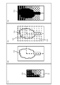
図10(1)は、図9(2)の符号510付近を拡大し、立体物51の輪郭を重畳した図である。図10(2)は、図10(1)において測定範囲の境界を示す図である。図10(3)は、図10(2)の図に対して、テーブルデータ107の座標対応画素を重畳した図である。
図10(3)における座標対応画素は、バツ印(×)、丸印(○)、三角印(△)の3種類で示している。バツ印は、距離情報が得られている点を示す。丸印は、立体物51に該当する箇所であって、距離情報が得られていない点を示す。三角印は、地面に該当する箇所であって、距離情報が得られていない点を示す。
例えば符号512で示す丸印は、立体物51の一部なので、立体物51の他の部位と略同一の距離に認識されるべきである。符号513で示す三角印の点は、地面に含まれる点であるため、符号55で示す地面部分と略同一の距離に認識されるべきである。
そこで、距離修正部102は、後述する処理により、図10(4)に示すように、距離情報を補正する。すなわち、距離修正部102により、図8に示した立体物距離が算出される。テーブル補正部103は、算出された立体物距離を用いて、テーブルデータ107を補正する。これにより、テーブルデータ107の全ての座標対応画素において、適切な変換が行われる。
(画像認識部の動作例)
図9(1)および図11を参照して、画像認識部101の動作例を説明する。画像認識部101は、図9(1)に示すカメラ20aの撮影画像505を処理対象として、前述の色情報を用いた手法等によるセグメント分割処理により、撮影画像を複数の領域、すなわちセグメントに分割する。
図11(1)では、立体物51が符号601で示す1つの領域と認識されており、マーカ52が符号603で示すように4つの領域に認識されている。符号602,604は、道路の白線に対応する。符号600は地平線に対応する。
図11(2)は、図11(1)に示すそれぞれのセグメントに便宜的に記号を付した図である。図11(2)に示すように、画像認識部101により撮影画像はSG11~SG19の9セグメントに分割されている。ただし、このセグメント分割では、各セグメントが立体物と路面のどちらであるかは区別されていない。
(距離修正部の動作)
距離修正部102は、セグメントごとに、そのセグメント内の座標対応点の距離を、次の3つのいずれかの方法で修正する。
第1の方法は、単純平均である。距離修正部102は、セグメント内の全ての座標対応点の距離情報の平均値を算出し、この平均値を処理対象セグメント内の全ての座標対応点の立体物距離とする。すなわち第1の方法によれば、セグメント内の全ての座標対応点は同一の立体物距離を有する。第1の方法を用いると、図10(3)のバツ印のうち立体物51に該当する距離情報がdn(nは立体物51に含まれるバツ印の個数)であるとき、図10(3)の丸印512には距離情報の平均値であるΣdn/nを与えることとなる。
第2の方法は、1次近似である。距離修正部102は、セグメント内の座標対応点について、それぞれの座標値と距離情報の相関を一次関数で近似する。距離修正部102は、その近似式に基づき、それぞれの座標対応点の立体物距離を決定する。すなわち第2の方法によれば、例えば、車両1に対して斜めに正対する壁の距離などを正確に算出することができる。第2の方法を用いると、図10(3)のバツ印のうち立体物51に該当する距離情報dn(nは立体物51に含まれるバツ印の個数)に対し最小二乗法を用いて、座標値(x,y)に対する距離情報dをd=f(x,y)として近似できるとき、図10(3)の丸印512の距離情報もf(x,y)を用いてから求めることとなる。
第3の方法は、多次元近似である。第3の方法は、第2の方法における近似を2次以上の多次元関数とするものである。第3の方法によれば、複雑な形状を有する物体の距離も正確に算出できる。
たとえば、図6に示すワールド座標系において距離検出部30を点S(xs,ys,zs)に設置したとき、撮影画像502中の点Prに対応する距離情報を示す点Pw1の座標は次のように求めることができる。点Sから点Pw1に引く線分がなす方位角をθa(Yx軸と平行のときα=0)、仰角をθeとすると、線分の長さである距離情報dを用いてxw1=d・cosθe・sinθa+xs、yw1=d・cosθe・cosθa+ys、zw1=R・sinθe+zsとして得ることができる。このとき、数1、数3に示すアフィン変換は、図6に示す各座標値を用いて、それぞれ数6、数7のように表すことができる。

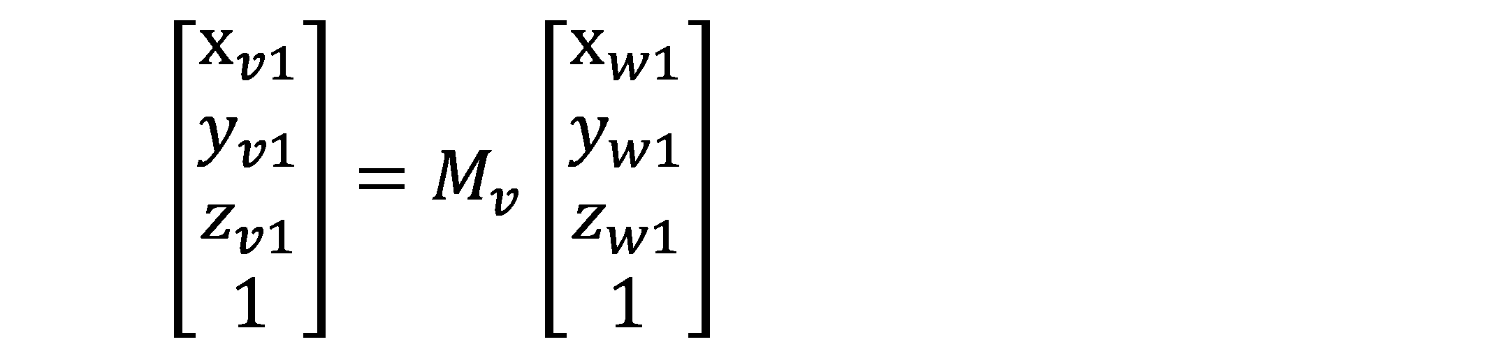
数6と数7を組み合わせて、撮影画像502の点Prを視点変換画像503の点に座標変換する式(数8)が得られる。
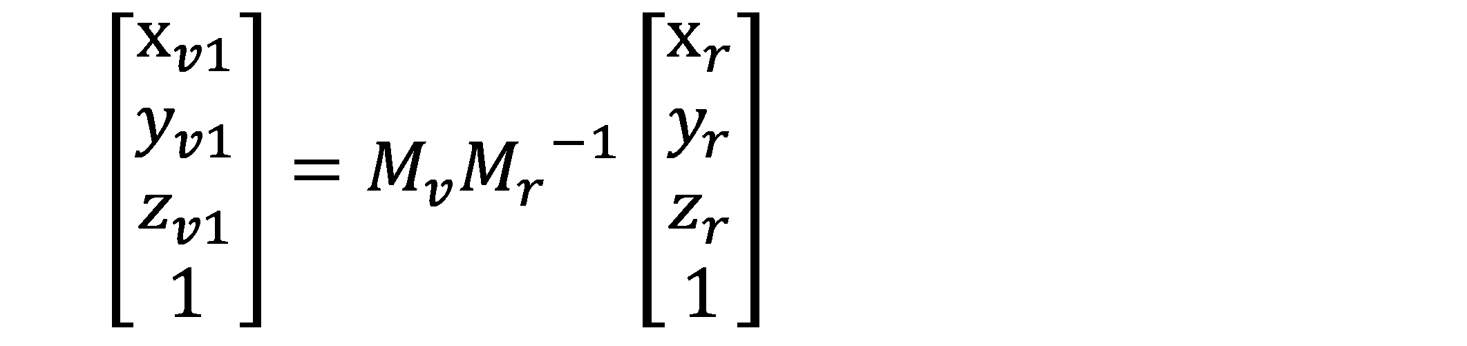
以上より、距離情報を用いることにより、撮影画像502中の点Prは視点変換画像503において、点Pvから点Pv1に補正されることとなる。
(画像処理装置の動作)
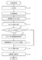
図12を参照して、視点変換画像をユーザインターフェース部40に表示する際の画像処理装置10の動作を説明する。以下に説明する画像処理装置10の動作は、所定の時間ごとに実行される。以下に説明する各ステップの実行主体は、CPU11である。但し、図12に示すステップ図は一例であり、以下に記載する処理が実現できるのであれば例えばS11とS12の順番が逆であってもよい。
まず始めに、CPU11は、距離検出部30から距離画像を取得する(S11)。CPU11は、カメラ20から撮影画像を取得する(S12)。CPU11は、ステップS12で取得した距離画像を画像認識部101に処理させることにより、セグメント分割を実行させる(S13)。ステップS13の例は、図11で説明したとおりである。
CPU11は、以下に説明するステップS15~S18を、ステップS13で算出された各セグメントに対して順番に実行する(S14)。全てのセグメントについて、平行してS15~S18の処理を実行してもよい。ここでは、処理対象を変化させて1つずつ順番にセグメントを処理する例を説明する。処理対象のセグメントを処理対象セグメントと呼ぶ。
CPU11は、処理対象セグメント内の距離情報に基づいて、その処理対象セグメントが立体物に対応する領域であるか、それとも路面に対応する領域であるかを判断する(S15)。
処理対象セグメントが立体物であるか否かの判断は、例えば以下のように行うことができる。すなわち、カメラ20の取付位置および取付姿勢は既知なので、対応付け部104は、撮影対象を路面と仮定することにより、撮影画像内の位置と距離との関係を予め算出できる。したがって、セグメント内の距離情報と、そのセグメントの撮影画像内の位置から算出される前述の距離との差を比較することにより、そのセグメントにおける被写体が路面であるか否か判断できる。
CPU11は、処理対象セグメントにおける被写体が立体物であると判断する場合はステップS16に進み、そのセグメントにおける被写体が路面であると判断する場合はステップS18に進む。距離が無限大または測定不能であると判定された場合および処理対象セグメントの被写体が空であると判断する場合は、ステップS18に進む。
ステップS16において、CPU11は、距離修正部102を用いて処理対象セグメント内の全ての座標対応点の距離情報を修正する。すなわちCPU11は、立体物距離を算出する。
続いてCPU11は、テーブル補正部103に対し、テーブルデータ107における処理対象セグメント内の全ての座標対応点について書き換えさせ(S17)、その後ステップS19へ進む。
ただしステップS17において補正されたテーブルデータ107は、後述するステップS19の実行完了後に破棄されるものである。すなわち、ステップS17の処理は、テーブルデータ107の一時的なコピーに対する補正である。
ステップS15において、処理対象セグメントが路面であると判断されると、ステップS18が実行される。この場合、CPU11は、テーブル補正部103にテーブルデータ107を補正させることなく、ステップS19へ進む。すなわちステップS18では、特段の処理を行わないので、ステップS15において路面であると判断された場合(S15:NO)、そのままステップS19へ進んでもよい。
ステップS18では、CPU11は、全てのセグメントを処理対象としたか否かを判断する。CPU11は、未処理のセグメントが存在すると判断すると、そのセグメントを処理対象に設定してステップS15へ戻る。CPU11は、全てのセグメントを処理対象にしたと判断すると、ステップS19へ進む。
ステップS19において、CPU11は、ステップS17で画像変換部105により補正されたテーブルデータ107を用いることにより、カメラ20の撮影画像を仮想視点53から見た視点変換画像に変換する。そして、ステップS19では、ユーザインターフェース制御部106が視点変換画像をユーザインターフェース部40に出力し、本処理を終了する。
このように構成される本実施例によれば、以下の作用効果を奏する。
本実施例に係る画像処理装置10は、撮影画像を取得するカメラ20と、距離画像を取得する距離検出部30と、撮影画像において立体物に対応する立体物領域を含む領域を抽出する画像認識部101と、距離画像に基づき立体物領域の奥行き情報を算出する距離修正部102と、撮影画像を座標変換するための座標変換情報であるテーブルデータ107を距離修正部102が算出した立体物領域の奥行き情報に基づき補正するテーブル補正部103と、テーブル補正部103により補正されたテーブルデータ107を用いて撮影画像を座標変換した視点変換画像を生成する画像変換部105と、を備える。したがって、本実施例によれば、距離画像の値を利用して平面画像中の立体物領域を立体的に処理し、視点変換画像を得ることができる。
本実施例に係る画像処理装置10では、距離検出部30が距離画像を取得する距離画像取得範囲A30は、カメラ20が平面画像を取得する平面画像取得範囲A20よりも小さく、かつ、平面画像取得範囲A20の一部に重なるように設定されている。したがって、本実施例の画像処理装置10によれば、カメラ20と比較して測定範囲が狭い距離画像を用いる場合でも、距離画像の測定範囲を超えた広範囲の立体物について高精度な視点変換画像を生成することができる。
本実施例に係る画像認識部101は、撮影画像の輝度、明度、彩度、および明度の少なくとも1つに基づき立体物領域を含む複数のセグメントの輪郭を抽出する。そのため画像認識部101は撮影画像を容易に立体物領域を含む複数のセグメントに分割することができる。
本実施例では、テーブルデータ107は、撮影画像上の変換元座標と視点変換画像上の変換先座標との組み合わせを複数含む。テーブル補正部103は、距離画像における立体物領域の距離情報に基づき、図8に示すように変換先座標、すなわち視点変換画像上の座標を補正する。これにより本実施例では、距離画像を取得していない測定範囲外についても距離情報を与えることができる。
本実施例では、テーブルデータ107は、撮影画像における被写体が路面上の領域であることを前提として予め作成される。画像認識部101は、撮影画像に含まれる被写体ごとに撮影画像を複数のセグメントに分割する。テーブル補正部103は、距離画像に基づき複数のセグメントが立体物領域であるか否かをそれぞれ判断し(図12のS15)、立体物領域であると判断したセグメント内の変換元座標に対応する変換先座標をテーブルデータ107において補正する(S17)。これにより本実施例では、立体物ではない領域についてはテーブルデータ107の補正を行う必要がなく、処理時間を短縮することができる。
本実施例では、テーブルデータ107は、撮影画像の被写体が基準高さ平面内に存在することを前提に算出される。テーブル補正部103は、距離修正部102が算出した立体物領域の奥行き情報を用いて被写体の基準高さ平面501からの高さ、および被写体の基準高さ平面上の位置を算出する。さらにテーブル補正部103は、視点変換の基準位置、算出した被写体の基準高さ平面からの高さ、および算出した被写体の基準高さ平面上の位置を用いてテーブルデータ107を補正する。
(変形例1)
第1実施例の変形例を説明する。以下、第1実施例との相違を中心に述べる。第1実施例におけるテーブルデータ107は、上述した数5により表される撮影画像上の点Prと視点変換画像上の点Pvとの対応関係を示すものであった。
しかし、テーブルデータ107は、数1により表される撮影画像上の点Prと三次元空間上の点Pwとの対応関係を示すものであってもよい。本変形例におけるテーブルデータを第1実施例におけるテーブルデータ107と区別するために、以下ではテーブルデータ107bと呼ぶ。
本変形例においては、テーブルデータ107bを補正することにより、3次元区間上に投影される撮影画像が変形される。画像変換部105は、3次元空間上に投影された撮影画像を仮想視点から撮影した画像、すなわち視点変換画像を作成する。
図13は、テーブルデータ107bの一例を示す。テーブルデータ107bは、数1により表される撮影画像502上の点Prと三次元空間上の点Pwとの対応関係を示すものである。ただし本変形例では、補正前のテーブルデータ107bにおいて、3次元空間上の点PwのZw座標の値は全てゼロである。すなわち補正前のテーブルデータ107bは、撮影画像502上の点Prと三次元空間上のZw=0の平面上の点Pwとの対応関係を示す。
このように構成される本変形例によれば、事前に想定していない仮想視点がユーザにより設定された場合であっても、テーブルデータ107bを用いて視点変換画像を作成することができる。
(変形例2)
第2の変形例を説明する。第1実施例のテーブルデータ107は、被写体がすべて路面上に存在するとの仮定の下で予め作成されていた。しかし、テーブルデータ107を予め作成せず随時作成してもよい。この場合、図12に示す処理において、テーブルデータ107が作成される。すなわちステップS17において、テーブルデータ107のうち該当する箇所が作成される。テーブルデータ107を随時作成することにより、記憶領域の使用量を低減することができる。
(変形例3)
第3変形例を説明する。第1実施例では、車両1は前カメラ20a、左カメラ20b、右カメラ20c、および後カメラ20dの4つのカメラを備えた。しかし車両1は少なくとも1つのカメラを備えればよい。車両1は、5つ以上のカメラを備えてもよい。
(変形例4)
第4変形例を説明する。第1実施例では、画像認識部101がセグメント分割処理を行うことで撮影画像を複数の領域に分割する。そして、第1実施例では、立体物に対応する領域の座標対応点を処理対象として、テーブル補正部103がテーブルデータ107の補正を行う。
これに代えて、画像認識部101は、撮影画像内で立体物に対応する領域のみを特定してもよい。例えば、距離画像において奥行き情報が段階的に変化していない部分を抽出し、その部分に対応する同一被写体の領域を撮影画像において特定することで、立体物に対応する領域を撮影画像内で特定することが可能である。
(変形例5)
第5変形例を説明する。第1実施例では、テーブルデータ107は、被写体がすべて路面上に存在するとの仮定の下で予め作成されていた。しかし、一定の立体形状に沿って存在するとの仮定の下でテーブルデータ107を予め作成してもよい。例えば、車両中心を原点とした球を設定して、テーブルデータ107を作成しても良い。
なお、本発明は上記各実施例に限定されるものではなく、様々な変形例が含まれる。例えば、上記各実施例は本発明を分かりやすく説明するために詳細に記載したものであり、必ずしも説明した全ての構成を備えるものに限定されるものではない。
上記の各構成、機能、処理部、および処理手段等は、それらの一部または全部を、例えば集積回路で設計する等によりハードウェアで実現してもよい。
上記の各構成、および機能等は、プロセッサがそれぞれの機能を実現するプログラムを解釈し、実行することによりソフトウェアで実現してもよい。 各機能を実現するプログラム、テーブル、ファイル等の情報は、メモリや、ハードディスク、SSD等の記録装置、または、ICカード、SDカード、DVD等の記録媒体に置くことができる。
制御線や情報線は説明上必要と考えられるものを示しており、製品上必ずしも全ての制御線や情報線を示しているとは限らない。実際には殆ど全ての構成が相互に接続されていると考えてもよい。
本発明の各構成要素は、任意に取捨選択することができ、取捨選択した構成を具備する発明も本発明に含まれる。さらに特許請求の範囲に記載された構成は、特許請求の範囲で明示している組合せ以外にも組み合わせることができる。
1:車両、10:画像処理装置、20a~20d,20:カメラ、30:距離検出部、40:ユーザインターフェース部、101:画像認識部、102:距離修正部、103:テーブル補正部、104:対応付け部、105:画像変換部、106:ユーザインターフェース制御部、107:テーブルデータ、108:距離画像認識部
Claims (13)
- 平面画像取得部から取得する平面画像から立体物の範囲に相当する立体物領域を抽出する画像認識部と、
前記立体物領域の奥行き情報を、距離画像取得部から取得する奥行き情報を有する距離画像に基づいて算出する距離修正部と、
前記平面画像中の一部領域に該当する奥行き情報を前記距離画像中の一部領域から特定する対応付け部と、
前記平面画像を所定の視点から見える視点変換画像に座標変換する座標変換情報を、前記算出された前記立体物領域の奥行き情報に基づいて補正するテーブル補正部と、
前記補正された座標変換情報を用いて前記平面画像を座標変換することにより、前記視点変換画像を生成する画像変換部と、
を備える画像処理装置。 - 前記距離画像取得部が前記距離画像を取得する距離画像取得範囲は、前記平面画像取得部が前記平面画像を取得する平面画像取得範囲よりも小さく、かつ、前記平面画像取得範囲の一部に重なるように設定されている、
請求項1に記載の画像処理装置。 - 前記画像認識部は、前記平面画像の輝度、明度、彩度、または明度のうち少なくとも1つに基づいて、前記立体物領域を含む複数の領域の輪郭を抽出する、
請求項1または2のいずれか一項に記載の画像処理装置。 - 前記座標変換情報は、前記平面画像上の変換元座標と前記視点変換画像上の変換先座標との組み合わせを複数含み、
前記テーブル補正部は、前記算出された立体物領域の奥行き情報に基づいて、前記変換先座標を補正する、
請求項1または2のいずれか一項に記載の画像処理装置。 - 前記座標変換情報は、前記平面画像が地面の被写体を写した画像であるとして予め作成されており、
前記画像認識部は、前記平面画像に含まれる前記被写体ごとに、前記平面画像を複数の領域に分割し、
前記テーブル補正部は、前記距離画像に基づいて、前記分割された複数の領域が前記立体物領域であるか否かを判断し、前記立体物領域であると判断した領域について、当該領域内の前記変換元座標に対応する前記変換先座標を補正する、
請求項4に記載の画像処理装置。 - 前記座標変換情報は、前記平面画像上の変換元座標と前記視点変換画像上の変換先座標との組み合わせを複数含み、
前記テーブル補正部は、前記変換元座標を前記立体物領域の輪郭の所定範囲内に位置するように補正する、
請求項1または2のいずれか一項に記載の画像処理装置。 - 前記テーブル補正部は、前記立体物領域の輪郭の前記所定範囲内であって、前記立体物領域の外部または内部の少なくともいずれかに前記変換元座標を配置する、
請求項6に記載の画像処理装置。 - 前記座標変換情報は、前記平面画像内の被写体が予め設定される基準高さを持つ基準高さ平面内に存在することを前提に算出されており、
前記テーブル補正部は、
前記距離修正部が算出した前記立体物領域の奥行き情報を用いることにより、前記被写体の前記基準高さ平面からの高さ、および前記被写体の前記基準高さ平面上での位置を算出し、
視点変換の基準位置と、算出した前記被写体の前記基準高さ平面からの高さと、算出した前記被写体の前記基準高さ平面上での位置とを用いることにより、前記座標変換情報を補正する、
請求項1または2のいずれか一項に記載の画像処理装置。 - 前記所定の視点は、前記平面画像取得部の視点と異なるように設定される仮想的な視点である、
請求項1または2のいずれか一項に記載の画像処理装置。 - 前記平面画像取得部が前記平面画像を取得する際の解像度は、前記距離画像取得部が前記距離画像を取得する際の解像度よりも大きく設定されており、
前記距離修正部は、前記立体物領域の奥行き情報を前記距離画像に基づいて補間して算出する、
請求項1または2のいずれか一項に記載の画像処理装置。 - 前記視点変換画像を表示部に表示させる表示制御部をさらに備える、
請求項1または2のいずれか一項に記載の画像処理装置。 - 画像を処理する画像処理方法であって、
カメラを用いて平面画像を取得し、
距離検出部を用いて奥行き情報を有する距離画像を取得し、
前記平面画像から立体物の範囲に相当する立体物領域を抽出し、
前記立体物領域の奥行き情報を前記距離画像に基づいて算出し、
前記算出された前記立体物領域の奥行き情報に基づいて前記平面画像を座標変換することにより、所定の視点から見える視点変換画像を生成する、
画像処理方法。 - 前記距離画像を取得する距離画像取得範囲は、前記平面画像を取得する平面画像取得範囲よりも小さく、かつ、前記平面画像取得範囲の一部に重なるように設定される、
請求項12に記載の画像処理方法。
Applications Claiming Priority (2)
| Application Number | Priority Date | Filing Date | Title |
|---|---|---|---|
| JP2018077449A JP7074546B2 (ja) | 2018-04-13 | 2018-04-13 | 画像処理装置および方法 |
| JP2018-077449 | 2018-04-13 |
Publications (1)
| Publication Number | Publication Date |
|---|---|
| WO2019198399A1 true WO2019198399A1 (ja) | 2019-10-17 |
Family
ID=68163565
Family Applications (1)
| Application Number | Title | Priority Date | Filing Date |
|---|---|---|---|
| PCT/JP2019/009588 Ceased WO2019198399A1 (ja) | 2018-04-13 | 2019-03-11 | 画像処理装置および方法 |
Country Status (2)
| Country | Link |
|---|---|
| JP (1) | JP7074546B2 (ja) |
| WO (1) | WO2019198399A1 (ja) |
Cited By (3)
| Publication number | Priority date | Publication date | Assignee | Title |
|---|---|---|---|---|
| CN113436241A (zh) * | 2021-06-25 | 2021-09-24 | 兰剑智能科技股份有限公司 | 一种采用深度信息的干涉校验方法及系统 |
| CN115434519A (zh) * | 2022-09-29 | 2022-12-06 | 中铁八局集团第一工程有限公司 | 电动式钢筋预绑扎台车 |
| CN119761310A (zh) * | 2024-12-27 | 2025-04-04 | 北京市测绘设计研究院 | 三维数据的基准转换方法、装置、计算机设备和存储介质 |
Families Citing this family (2)
| Publication number | Priority date | Publication date | Assignee | Title |
|---|---|---|---|---|
| JP2024089707A (ja) * | 2022-12-22 | 2024-07-04 | 株式会社Jvcケンウッド | 三次元情報補正装置及び三次元情報補正方法 |
| KR102893481B1 (ko) * | 2024-10-21 | 2025-12-01 | 케이엠아이에스 주식회사 | 카메라 영상을 이용한 지표면과 장애물 인식 단말 및 인식 방법 |
Citations (4)
| Publication number | Priority date | Publication date | Assignee | Title |
|---|---|---|---|---|
| JP2009118415A (ja) * | 2007-11-09 | 2009-05-28 | Alpine Electronics Inc | 鳥瞰画像生成装置および方法 |
| JP2011188335A (ja) * | 2010-03-10 | 2011-09-22 | Clarion Co Ltd | 車両用周囲監視装置 |
| JP2012147149A (ja) * | 2011-01-11 | 2012-08-02 | Aisin Seiki Co Ltd | 画像生成装置 |
| JP2018014583A (ja) * | 2016-07-20 | 2018-01-25 | クラリオン株式会社 | 画像処理装置 |
-
2018
- 2018-04-13 JP JP2018077449A patent/JP7074546B2/ja not_active Expired - Fee Related
-
2019
- 2019-03-11 WO PCT/JP2019/009588 patent/WO2019198399A1/ja not_active Ceased
Patent Citations (4)
| Publication number | Priority date | Publication date | Assignee | Title |
|---|---|---|---|---|
| JP2009118415A (ja) * | 2007-11-09 | 2009-05-28 | Alpine Electronics Inc | 鳥瞰画像生成装置および方法 |
| JP2011188335A (ja) * | 2010-03-10 | 2011-09-22 | Clarion Co Ltd | 車両用周囲監視装置 |
| JP2012147149A (ja) * | 2011-01-11 | 2012-08-02 | Aisin Seiki Co Ltd | 画像生成装置 |
| JP2018014583A (ja) * | 2016-07-20 | 2018-01-25 | クラリオン株式会社 | 画像処理装置 |
Cited By (4)
| Publication number | Priority date | Publication date | Assignee | Title |
|---|---|---|---|---|
| CN113436241A (zh) * | 2021-06-25 | 2021-09-24 | 兰剑智能科技股份有限公司 | 一种采用深度信息的干涉校验方法及系统 |
| CN115434519A (zh) * | 2022-09-29 | 2022-12-06 | 中铁八局集团第一工程有限公司 | 电动式钢筋预绑扎台车 |
| CN115434519B (zh) * | 2022-09-29 | 2023-08-22 | 中铁八局集团第一工程有限公司 | 电动式钢筋预绑扎台车 |
| CN119761310A (zh) * | 2024-12-27 | 2025-04-04 | 北京市测绘设计研究院 | 三维数据的基准转换方法、装置、计算机设备和存储介质 |
Also Published As
| Publication number | Publication date |
|---|---|
| JP2019185520A (ja) | 2019-10-24 |
| JP7074546B2 (ja) | 2022-05-24 |
Similar Documents
| Publication | Publication Date | Title |
|---|---|---|
| JP5491235B2 (ja) | カメラキャリブレーション装置 | |
| US9858639B2 (en) | Imaging surface modeling for camera modeling and virtual view synthesis | |
| JP6891954B2 (ja) | 物体検知装置、物体検知方法、及びプログラム | |
| JP5944687B2 (ja) | 外因パラメータのみのサラウンドビューカメラ自動較正 | |
| JP3284190B2 (ja) | ステレオカメラの画像補正装置 | |
| JP7074546B2 (ja) | 画像処理装置および方法 | |
| US20100246901A1 (en) | Operation Support System, Vehicle, And Method For Estimating Three-Dimensional Object Area | |
| US20080181488A1 (en) | Camera calibration device, camera calibration method, and vehicle having the calibration device | |
| JP5456330B2 (ja) | 画像表示装置及びそのカメラ取り付け角度算出方法 | |
| KR20220113781A (ko) | 환경의 지형을 측정하는 방법 | |
| CN106464847A (zh) | 影像合成系统和用于其的影像合成装置与影像合成方法 | |
| JPWO2009119110A1 (ja) | 死角表示装置 | |
| JP7247173B2 (ja) | 画像処理方法及び装置 | |
| JP2011215063A (ja) | カメラ姿勢パラメータ推定装置 | |
| JP2022547531A (ja) | センサフュージョンに基づく知覚的に向上したサラウンドビュー | |
| JP2019012915A (ja) | 画像処理装置、画像変換方法 | |
| JP5178454B2 (ja) | 車両周囲監視装置及び車両周囲監視方法 | |
| KR20170001765A (ko) | Avm 시스템의 공차 보정 장치 및 방법 | |
| JP7196920B2 (ja) | 運転支援装置および運転支援方法、プログラム | |
| JP2009077022A (ja) | 運転支援システム及び車両 | |
| WO2015182771A1 (ja) | 撮像装置、画像処理装置、画像処理方法およびコンピュータプログラム | |
| TWM591940U (zh) | 全景停車輔助系統及其裝置 | |
| JP6734136B2 (ja) | 画像処理装置 | |
| JP2013200840A (ja) | 映像処理装置、映像処理方法、映像処理プログラム、及び映像表示装置 | |
| KR20110082873A (ko) | 복수개의 영상을 합성한 합성 영상에서 거리 정보를 제공하는 기능을 구비하는 영상 처리 장치 및 방법 |
Legal Events
| Date | Code | Title | Description |
|---|---|---|---|
| 121 | Ep: the epo has been informed by wipo that ep was designated in this application |
Ref document number: 19784991 Country of ref document: EP Kind code of ref document: A1 |
|
| NENP | Non-entry into the national phase |
Ref country code: DE |
|
| 122 | Ep: pct application non-entry in european phase |
Ref document number: 19784991 Country of ref document: EP Kind code of ref document: A1 |