WO2019196398A1 - 一种轨道式大跨度可折展加工机器人 - Google Patents
一种轨道式大跨度可折展加工机器人 Download PDFInfo
- Publication number
- WO2019196398A1 WO2019196398A1 PCT/CN2018/114135 CN2018114135W WO2019196398A1 WO 2019196398 A1 WO2019196398 A1 WO 2019196398A1 CN 2018114135 W CN2018114135 W CN 2018114135W WO 2019196398 A1 WO2019196398 A1 WO 2019196398A1
- Authority
- WO
- WIPO (PCT)
- Prior art keywords
- link
- hinge point
- freedom
- branch
- degree
- Prior art date
- Legal status (The legal status is an assumption and is not a legal conclusion. Google has not performed a legal analysis and makes no representation as to the accuracy of the status listed.)
- Ceased
Links
Images




Classifications
-
- B—PERFORMING OPERATIONS; TRANSPORTING
- B25—HAND TOOLS; PORTABLE POWER-DRIVEN TOOLS; MANIPULATORS
- B25J—MANIPULATORS; CHAMBERS PROVIDED WITH MANIPULATION DEVICES
- B25J5/00—Manipulators mounted on wheels or on carriages
-
- B—PERFORMING OPERATIONS; TRANSPORTING
- B25—HAND TOOLS; PORTABLE POWER-DRIVEN TOOLS; MANIPULATORS
- B25J—MANIPULATORS; CHAMBERS PROVIDED WITH MANIPULATION DEVICES
- B25J5/00—Manipulators mounted on wheels or on carriages
- B25J5/02—Manipulators mounted on wheels or on carriages travelling along a guideway
-
- B—PERFORMING OPERATIONS; TRANSPORTING
- B25—HAND TOOLS; PORTABLE POWER-DRIVEN TOOLS; MANIPULATORS
- B25J—MANIPULATORS; CHAMBERS PROVIDED WITH MANIPULATION DEVICES
- B25J18/00—Arms
-
- B—PERFORMING OPERATIONS; TRANSPORTING
- B25—HAND TOOLS; PORTABLE POWER-DRIVEN TOOLS; MANIPULATORS
- B25J—MANIPULATORS; CHAMBERS PROVIDED WITH MANIPULATION DEVICES
- B25J9/00—Program-controlled manipulators
-
- B—PERFORMING OPERATIONS; TRANSPORTING
- B25—HAND TOOLS; PORTABLE POWER-DRIVEN TOOLS; MANIPULATORS
- B25J—MANIPULATORS; CHAMBERS PROVIDED WITH MANIPULATION DEVICES
- B25J9/00—Program-controlled manipulators
- B25J9/0009—Constructional details, e.g. manipulator supports, bases
-
- B—PERFORMING OPERATIONS; TRANSPORTING
- B25—HAND TOOLS; PORTABLE POWER-DRIVEN TOOLS; MANIPULATORS
- B25J—MANIPULATORS; CHAMBERS PROVIDED WITH MANIPULATION DEVICES
- B25J9/00—Program-controlled manipulators
- B25J9/003—Program-controlled manipulators having parallel kinematics
- B25J9/0033—Program-controlled manipulators having parallel kinematics with kinematics chains having a prismatic joint at the base
-
- B—PERFORMING OPERATIONS; TRANSPORTING
- B25—HAND TOOLS; PORTABLE POWER-DRIVEN TOOLS; MANIPULATORS
- B25J—MANIPULATORS; CHAMBERS PROVIDED WITH MANIPULATION DEVICES
- B25J9/00—Program-controlled manipulators
- B25J9/003—Program-controlled manipulators having parallel kinematics
- B25J9/0072—Program-controlled manipulators having parallel kinematics of the hybrid type, i.e. having different kinematics chains
-
- B—PERFORMING OPERATIONS; TRANSPORTING
- B25—HAND TOOLS; PORTABLE POWER-DRIVEN TOOLS; MANIPULATORS
- B25J—MANIPULATORS; CHAMBERS PROVIDED WITH MANIPULATION DEVICES
- B25J9/00—Program-controlled manipulators
- B25J9/02—Program-controlled manipulators characterised by movement of the arms, e.g. cartesian coordinate type
- B25J9/04—Program-controlled manipulators characterised by movement of the arms, e.g. cartesian coordinate type by rotating at least one arm, excluding the head movement itself, e.g. cylindrical coordinate type or polar coordinate type
-
- B—PERFORMING OPERATIONS; TRANSPORTING
- B25—HAND TOOLS; PORTABLE POWER-DRIVEN TOOLS; MANIPULATORS
- B25J—MANIPULATORS; CHAMBERS PROVIDED WITH MANIPULATION DEVICES
- B25J9/00—Program-controlled manipulators
- B25J9/10—Program-controlled manipulators characterised by positioning means for manipulator elements
- B25J9/106—Program-controlled manipulators characterised by positioning means for manipulator elements with articulated links
- B25J9/1065—Program-controlled manipulators characterised by positioning means for manipulator elements with articulated links with parallelograms
Definitions
- the invention belongs to the field of mechanical design and manufacture, and particularly relates to a track type long-span foldable processing robot which can be applied in the field of numerical control processing.
- the object of the present invention is to provide a better principle configuration and solution for large-scale component processing, and propose a track-type long-span foldable processing robot.
- the novel processing robot proposed by the present invention utilizes two parallelogram structures coupled. As well as the track, the space of the five-degree-of-freedom end attitude adjusting device can be moved and positioned in a large range, and the large working space requirement of the large-scale structural parts for the processing equipment is required, and the functions of large-scale positioning and partial flexible posture adjustment are easily realized.
- a track type long-span foldable processing robot includes: a track, a five-degree-of-freedom end attitude adjusting device, and a two-degree-of-freedom foldable mechanism, the two-degree-of-freedom foldable mechanism comprising: a base a first parallelogram structure, a second parallelogram structure, an intermediate triangular plate, a first drive assembly and a second drive assembly, the first parallelogram structure being mounted on the base, the first parallelogram structure and the second stage a parallelogram structure is coupled by the intermediate triangular plate, the base is fitted on the rail, the base has spaced apart first hinge points and second hinge points, and the middle triangular plate has a third hinge which is triangularly distributed a first parallel joint structure, wherein the first parallel link structure includes: a first link and a second link, wherein two ends of the first link are respectively hingedly connected to the first hinge point And the fourth hinge point, the two ends of the second link are respectively hingedly connected to the second hinge point and the third
- a track type long-span foldable processing robot realizes three rotational degrees of freedom and two degrees of freedom by providing three branch structures to form a five-degree-of-freedom end attitude adjusting device, which is the mechanism
- the moving platform can realize large rotational output capability;
- the two-degree-of-freedom foldable mechanism adopting two-stage parallelogram structure can drive the two-degree-of-freedom foldable mechanism by controlling two inputs. Movement can guarantee a higher normal stiffness of the machined surface, which is not possible with ordinary robots.
- the two-degree-of-freedom foldable mechanism can be moved on the track to achieve three degrees of rotational freedom in the plane.
- the rail type long-span foldable processing robot proposed by the invention can cope with the working space requirement of large structural parts for processing equipment, and is easy to realize functions of large-scale positioning and local flexible posture adjustment, and can complete numerical control of complex free-form surfaces of large structural parts. machining.
- the first-order parallelogram structure and the second-order parallelogram structure are parallelograms, and the two parallelograms are coupled through the intermediate triangular plate, thereby controlling two sides of the two parallelograms by
- the angle between the bases gives the unique position of the five-degree-of-freedom end attitude adjustment device, enabling a wide range of movement and positioning of the end five-degree-of-freedom end attitude adjustment device.
- the two-degree-of-freedom foldable mechanism is mounted on the track, and the two-degree-of-freedom foldable mechanism can be adjusted along the track large-span position, thereby finally realizing the wide-range movement and positioning capability of the five-degree-of-freedom end attitude adjusting device.
- the orbital long-span foldable machining robot further includes: a converted parallelogram structure including a sixth link and a seventh link, one end of the sixth link being hingedly connected On the first hinge point, the other end of the sixth link is hingedly connected to one end of the seventh link, and the other end of the seventh link is hingedly connected to the third link a portion of the first link, the sixth link, the seventh link, and the third link form a quadrangle, and the second drive assembly rotates by driving the sixth link Driving the third link to rotate.
- a converted parallelogram structure including a sixth link and a seventh link, one end of the sixth link being hingedly connected On the first hinge point, the other end of the sixth link is hingedly connected to one end of the seventh link, and the other end of the seventh link is hingedly connected to the third link a portion of the first link, the sixth link, the seventh link, and the third link form a quadrangle, and the second drive assembly rotates by driving the sixth link Driving the third link to rotate.
- the track includes two parallel disposed, the bottom of the base being fitted to the two tracks by a slider, and each of the tracks is provided with a plurality of the sliders.
- the first drive assembly and the second drive assembly are respectively cylinder drive mechanisms.
- the first drive component and the second drive component are respectively motor drive mechanisms.
- the first driving component includes: a first top block, the first top block is rotatably coupled to the first link; and the first branch block, the first branch block is Rotatingly coupled to the base; a first driving rod, one end of the first driving rod is connected to the first top block, and the other end of the first driving rod is connected to the first branch block a first driving rod, a partial section of the first link, the base forming a triangle; a first driver, the first driver for driving the first driving rod relative to the first top block or the The first block is stretched.
- the second drive assembly includes: a second top block rotatably coupled to the third link; and a second block, the second block Rotatingly connected to the intermediate triangular plate; a second driving rod, one end of the second driving rod is connected to the second top block, and the other end of the second driving rod is connected to the second branch
- the second branch is telescopic.
- the second drive assembly includes: a third top block rotatably coupled to the sixth link; a third branch, the third block Rotatablely coupled to the base; a third driving rod, one end of the third driving rod is connected to the third top block, and the other end of the third driving rod is connected to the third branch
- the third driving rod, a portion of the sixth connecting rod, the base constitutes a triangle; a third driver, the third driver is configured to drive the third driving rod relative to the third top block or Said third block expansion and contraction.
- the intermediate triangular plates are two disposed in parallel, two of the intermediate triangular plates are sandwiched on two sides of the first connecting rod and the third connecting rod, and the second connecting rod is Two parallelly arranged, the fourth link is two disposed in parallel, two of the second links are respectively hinged with two of the intermediate triangular plates, and the two of the fourth links are respectively connected to two The middle triangular plate is hinged.
- the base includes a bottom plate and a boss, the bottom plate is horizontally disposed, and the bottom plate is formed in a frame shape with an open rear side, and the bosses are two and are respectively disposed on the left and right sides of the bottom plate, the one A level parallelogram structure is attached to the two bosses.
- FIG. 1 is a perspective view of a track type long span foldable machining robot according to an embodiment of the present invention
- Figure 2 is a side view of the orbital long-span foldable machining robot shown in Figure 1;
- Figure 3 is a front elevational view of the two-degree-of-freedom foldable mechanism shown in Figure 1;
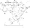
- Figure 4 is a schematic configuration diagram of the two-degree-of-freedom foldable mechanism shown in Figure 3;
- FIG. 5 is a perspective view of another orbital long-span foldable machining robot according to an embodiment of the present invention.
- Figure 6 is a side view of the rail type long-span foldable machining robot shown in Figure 5;
- Figure 7 is a front elevational view of the two-degree-of-freedom foldable mechanism shown in Figure 5;
- Figure 8 is a schematic configuration diagram of the two-degree-of-freedom foldable mechanism shown in Figure 7;
- FIG. 9 is a plan view of a five-degree-of-freedom end attitude adjusting device according to an embodiment of the present invention.
- Figure 10 is a perspective view of a five-degree-of-freedom end attitude adjusting device in accordance with an embodiment of the present invention.
- first parallelogram structure 12 a first link 121, a pole 1211, a second link 122,
- a second parallelogram structure 13 a third link 131, a fourth link 132, a fifth link 133,
- the first driving component 16 the first top block 161, the first branch block 162, the first driving rod 163,
- a second driving component 17 a second top block 171, a second branch 172, a second driving rod 173, a third top block 175, a third branch 176, a third driving rod 177,
- first hinge point j1 a first hinge point j1, a second hinge point j2, a third hinge point j3, a fourth hinge point j4, a fifth hinge point j5,
- connection In the description of the present invention, it should be noted that the terms “installation”, “connected”, and “connected” are to be understood broadly, and may be fixed or detachable, for example, unless otherwise explicitly defined and defined. Connected, or integrally connected; can be mechanical or electrical; can be directly connected, or indirectly connected through an intermediate medium, can be the internal communication of the two components.
- Connected, or integrally connected can be mechanical or electrical; can be directly connected, or indirectly connected through an intermediate medium, can be the internal communication of the two components.
- the specific meaning of the above terms in the present invention can be understood in a specific case by those skilled in the art.
- a rail type long span foldable machining robot 100 will now be described with reference to Figs.
- a track type long-span foldable processing robot 100 includes: a track 30, a five-degree-of-freedom end attitude adjusting device 2, and a two-degree-of-freedom folding mechanism 1 .
- the five-degree-of-freedom end posture adjusting device 2 is for adjusting the posture of the actuator 6, and the actuator 6 is an execution terminal of the processing device.
- the actuator 6 may be a cutter, a laser emitter, a nozzle, etc., and the type of the actuator 6 is not used here. Specific restrictions.
- the five-degree-of-freedom end attitude adjusting device 2 itself has the actuator 6 having an attitude adjustment capability in five degrees of freedom, specifically, the actuator 6 having rotational freedom in three directions and freedom of movement in both directions.
- the five-degree-of-freedom end posture adjusting device 2 can only adjust the posture of the actuator 6 within a small range.
- the processing of the actuator 6 is adjusted only by the five-degree-of-freedom end posture adjusting device 2. The space is limited, and it is impossible to realize the processing of large structural parts.
- the five-degree-of-freedom end attitude adjusting device 2 is mounted on the two-degree-of-freedom foldable mechanism 1, and the two-degree-of-freedom foldable mechanism 1 is similar to the structure of an industrial robot.
- the amplitude shifts the five-degree-of-freedom end attitude adjusting device 2.
- the two-degree-of-freedom foldable mechanism 1 is disposed on the rail 30, and an active driving structure (not shown) is disposed between the two-degree-of-freedom deflectable mechanism 1 and the rail 30, and the active driving structure can drive two degrees of freedom.
- the foldable mechanism 1 moves along the track 30, and the two-degree-of-freedom foldable mechanism 1 can have three degrees of freedom of rotation with the track 30 to achieve a wide range of positioning, and the five-degree-of-freedom end attitude adjusting device 2 after a large range of positioning Perform partial attitude adjustment.
- the combination of the two is equivalent to combining the macroscopic positioning and microscopic positioning of the processing, increasing the macroscopic positioning range and ensuring the microscopic positioning accuracy. Therefore, the problem that the two-degree-of-freedom foldable mechanism 1 and the five-degree-of-freedom end posture adjusting device 2 can not process the long-shaped parts can be solved, so that the applicable range of the orbital-type long-span foldable processing robot 100 of the embodiment of the present invention is solved. More extensive.
- the two-degree-of-freedom foldable mechanism 1 includes a base 11, a first-order parallelogram structure 12, a second-order parallelogram structure 13, an intermediate triangular plate 15, a first drive assembly 16, and a second drive assembly 17,
- the first parallelogram structure 12 is mounted on the base 11, and the first parallelogram structure 12 and the second parallelogram structure 13 are coupled by a middle triangular plate 15.
- the base 11 is fitted to the rail 30.
- the base 11 has a first hinge point j1 and a second hinge point j2 which are spaced apart, and the intermediate triangle plate 15 has a third hinge point j3 and a fourth portion which are triangularly distributed. Hinge point j4 and fifth hinge point j5.
- the first parallel link structure 12 includes a first link 121 and a second link 122.
- the two ends of the first link 121 are hingedly connected to the first hinge point j1 and the fourth hinge point j4, respectively.
- the second link 122 The two ends are hingedly connected to the second hinge point j2 and the third hinge point j3, respectively.
- the distance between the first hinge point j1 and the fourth hinge point j4 is equal to the distance between the second hinge point j2 and the third hinge point j3, and the line connecting the first hinge point j1 and the fourth hinge point j4 is the same as the second hinge point j2 and
- the lines of the third hinge point j3 are parallel to each other.
- the second parallelogram structure 13 includes: a third link 131, a fourth link 132 and a fifth link 133, the third link 131 is hingedly connected to the fourth hinge point j4, and the fourth link 132 is hingedly connected On the five-hinge point j5, both ends of the fifth link 133 pass through the sixth hinge point j6, the seventh hinge point j7, and the third link 131 and the fourth link 132, respectively.
- the distance between the fourth hinge point j4 and the sixth hinge point j6 is equal to the distance between the fifth hinge point j5 and the seventh hinge point j7, and the line connecting the fourth hinge point j4 and the sixth hinge point j6 is the same as the fifth hinge point j5 and The lines of the seventh hinge point j7 are parallel to each other.
- the third link 131, the fourth link 132, the fifth link 133, and the intermediate triangular plate 15 constitute another parallelogram.
- the intermediate triangle is a common component of the first parallelogram structure 12 and the second parallelogram structure 13, so that the action of the first parallelogram structure 12 is interlocked to the second parallelogram structure 13.
- the first driving assembly 16 is for driving one of the first link 121 and the second link 122 to rotate relative to the base 11, and the second driving assembly 17 is for driving one of the third link 131 and the fourth link 132 to be opposite.
- the intermediate triangular plate 15 is rotated, and the five-degree-of-freedom end posture adjustment device is coupled to the fifth link 133.
- the five-degree-of-freedom end attitude adjusting device 2 includes a fixed platform 21, a movable platform 22, a first branch 23, a second branch 24, and a third branch 25.
- the fixed platform 21 is fixedly connected to the fifth.
- the movable platform 22 is used for mounting the actuator 6, and the first branch 23, the second branch 24 and the third branch 25 are circumferentially disposed and connected between the fixed platform 21 and the movable platform 22, and the movable platform 22 It has three rotational degrees of freedom and two degrees of freedom of movement.
- the first branch 23 and the second branch 24 are identical in structure, each of which has two actively driven motion pairs, and the third branch 25 includes an actively driven motion pair;
- the branch 23, the second branch 24 and the third branch 25 are respectively connected with the fixed platform 21 and the movable platform 22 to form a spatial parallel closed-loop mechanism, and the spatial parallel closed-loop mechanism drives the moving platform through five input motions to realize three Rotation degrees of freedom and two degrees of freedom of movement.
- the parallel mechanism is a closed loop composed of two or more kinematic branches and can control the terminal to achieve a certain output motion. It has compact structure, small moving parts, high rigidity, good dynamic response characteristics, and large load capacity per unit weight. Easy to achieve high-speed motion. Therefore, the five-degree-of-freedom end attitude adjusting device 2 is an ideal choice for innovative design of processing equipment.
- the first-order parallelogram structure 12 and the second-order parallelogram structure 13 are parallelograms, and two parallelograms are coupled through the intermediate triangular plate 15.
- first parallelogram structure 12 is a parallelogram with the opposite sides of the same length, the angle of the swing of one of the first link 121 and the second link 122 is controlled, and the pose of the intermediate set 15 can be uniquely determined.
- the secondary parallelogram structure 13 is a parallelogram having the opposite sides of the same length, in the case where the posture of the intermediate triangular plate 15 is uniquely determined, one of the third link 131 and the fourth link 132 is controlled.
- the position of the five-degree-of-freedom end posture adjusting device 2 can be uniquely determined by the swing angle.
- a prominent effect of the coupling of the first parallelogram structure 12 and the second parallelogram structure 13 is that the position change is realized by the control of the swing angle of the two rods, and the effect is double superimposed, so that the five-degree-of-freedom end posture
- the adjustment device 2 is capable of large movement and positioning in the plane of the parallelogram.
- the combination of the rails 30 makes the two-degree-of-freedom foldable mechanism 1 also have the possibility of large-span movement in the Y-axis direction, and the combination of the two can realize all-round position and large-span adjustment.
- a rail type long-span foldable processing robot 100 is configured by forming three branch structures to form a five-degree-of-freedom end attitude adjusting device 2, thereby realizing three rotational degrees of freedom and two degrees of freedom of movement.
- the mechanism is distinguished from other similar mechanisms in that the dynamic platform 22 can realize a large rotational output capability; the two-degree-of-freedom foldable mechanism 1 adopting a two-stage parallelogram structure drives two degrees of freedom by controlling two inputs.
- the foldable mechanism 1 moves, and the two-degree-of-freedom foldable mechanism 1 moves on the track 30 to achieve three degrees of rotational freedom in the plane.
- Such a robot can ensure a high normal stiffness of the machined surface, which is not possible with ordinary robots.
- Such a track-type long-span foldable processing robot 100 can cope with the working space requirement of large structural parts for processing equipment, and is easy to realize functions of large-scale positioning and local flexible posture adjustment, and can complete numerical control processing of complex free-form surfaces of large structural parts. .
- the first branch 23 and the second branch 24 are identical in structure, each of which contains two actively driven motion pairs, and the third branch 25 contains an active drive pair.
- the first chain 23, the second branch 24 and the third branch 25 are respectively connected with the fixed platform 21 and the movable platform 22 to form a spatial parallel closed-loop mechanism, and the spatial parallel closed-loop mechanism drives the movable platform 22 through five input motions. Achieve three rotational degrees of freedom and two degrees of freedom of movement.
- the first branch 23 and the second branch 24 are symmetrically disposed with respect to the moving surface of the two-degree-of-freedom foldable mechanism 1. That is, in the example of FIG. 1, the two-degree-of-freedom foldable mechanism 1 has a symmetry plane in the left-right direction, and the first branch 23 and the second branch 24 are disposed opposite to the symmetry plane, and can maintain left-right balance under static conditions, and are placed for a long time. stable.
- the five-degree-of-freedom end attitude adjusting device 2 comprises: a fixed platform 21, a moving platform 22 and a first branch 23, a second branch 24, a third branch 25, and three branches.
- the chain is respectively connected between the fixed platform 21 and the movable platform 22, and forms a space closed loop mechanism with the fixed platform 21 and the movable platform 22.
- the first chain 23 and the second branch 24 each include: an upper connecting member 201, a lower connecting member 202, an upper sliding block 203, a sliding fast 204, an upper connecting rod 205, a lower connecting rod 206, a U-shaped member 207, and a connecting block. 208 and the sports officer.
- There are ten movement pairs one is a rotating pair connected between the fixed platform 21 and the lower connecting member 202, one is a rotating pair connected between the lower connecting member 202 and the lower sliding member 110, and the other is connected to the lower sliding block.
- a pair of movements between the 110 and the lower link 206 one is a rotating pair connected between the fixed platform 21 and the upper connecting member 201, and the other is a rotating pair connected between the upper connecting member 201 and the upper slider 203, one Is a moving pair connected between the upper slider 203 and the upper link 205, one is a rotating pair connected between the upper link 205 and the lower link 206, and one is connected to the upper link 205 and the U-shaped member 207
- a pair of rotations one is a rotating pair connected between the U-shaped member 207 and the connecting block 208, and the other is a rotating pair connected between the connecting block 208 and the movable platform 22.
- the moving pair connected between the upper slider 203 and the upper link 205 and the moving pair connected between the lower slider 110 and the lower link 206 are driven; connected to the fixed platform 21 and the upper connecting member 201
- the two rotating pairs between and connected between the upper connecting member 201 and the upper slider 203 may be replaced by a Hooke hinge or a ball joint; connected between the fixed platform 21 and the lower connecting member 202 and connected to the lower connecting member
- the two rotating pairs between the 202 and the lower slider 110 may be replaced by a Hooke hinge or a ball joint; connected between the upper link 205 and the U-shaped member 207, between the U-shaped member 207 and the connecting block 208.
- the three rotating pairs connected between the connecting block 208 and the moving platform 22 can be replaced by a ball joint; the branch is a space six degree of freedom unconstrained branch.
- the third branch 25 includes a connector 251, a slider 252, a link 253, and a motion pair.
- There are four movement pairs one is a rotating pair connected between the fixed platform 21 and the connecting member 251, one is a rotating pair connected between the connecting member 251 and the slider 252, and one is connected to the slider 252 and the connecting rod.
- the cylindrical pair between 253 and the other is a rotating pair connected between the link 253 and the movable platform 22.
- the telescopic movement between the slider 252 and the link 253 in the longitudinal direction of the rod is driven; the two rotations connected between the fixed platform 21 and the connecting member 251 and connected between the connecting member 251 and the slider 252
- the pair may be replaced by a Hooke hinge or a ball joint;
- the cylinder pair connected between the slider 252 and the link 253 may be replaced by a moving pair and a rotating pair, and the moving pair is driven;
- the branch has A space-free five-degree-of-freedom branch with a rotational constraint.
- the five-degree-of-freedom end attitude adjusting device 2 can realize five-axis linkage control of three rotational degrees of freedom and two degrees of freedom of movement.
- the third branch may also include a connector, a slider, a link, a U-shaped member, and a motion pair.
- There are three movement pairs one is a rotating pair connected between the connecting piece and the slider, one is a moving pair connected between the sliding block and the connecting rod, and the other is a rotation connected between the connecting rod and the U-shaped piece. vice. Among them, the moving pair connected between the slider and the connecting rod is driven.
- the track 30 includes two parallel disposed, and the bottom of the base 11 is fitted to the two rails 30 by a slider 31, and each of the rails 30 is provided with a plurality of sliders 31. This arrangement increases the smoothness of sliding along the track 30.
- the track 30 is a straight track extending in the horizontal direction.
- the extending direction of the track 30 may also be an arc shape or other curved shape, which is not limited herein.
- the intermediate triangular plates 15 are two disposed in parallel, and the two intermediate triangular plates 15 are sandwiched between the first link 121 and the third link 131.
- the second link 122 is two disposed in parallel
- the fourth link 132 is two disposed in parallel
- the two second links 122 are respectively hinged with the two intermediate triangular plates 15 and the two fourth links 132 is hinged to the two intermediate triangular plates 15, respectively.
- first link 121 and the third link 131 are set to be thick, and then the intermediate triangular plate 15, the second link 122, and the fourth link 132 are set flat, which can fully utilize the space and reduce the two degrees of freedom.
- the intermediate triangular plate 15, the second connecting rod 122, and the fourth connecting rod 132 are disposed in parallel and are located on both sides of the first connecting rod 121 and the third connecting rod 131, so that the first connecting rod 121 and the third connecting unit
- the rods 131 are evenly biased on both sides in the left-right direction, and the two-degree-of-freedom foldable mechanism 1 is prevented from swaying from side to side, further improving the dynamic characteristics of the mechanism.
- the base 11 includes a bottom plate 111 and a boss 112.
- the bottom plate 111 is horizontally disposed, and the bottom plate 111 is formed in a frame shape with an open rear side, and the boss 112 is two.
- the first parallelogram structure 12 is connected to the two bosses 112.
- the hinge shaft is disposed between the two bosses 112, thereby widening the width of the bottom left and right, improving structural stability and improving installation. Convenience.
- the first drive assembly 16 and the second drive assembly 17 are respectively cylinder drive mechanisms.
- the first drive assembly 16 and the second drive assembly 17 may employ an electric cylinder drive mechanism, a cylinder drive mechanism, or a hydraulic cylinder.
- the drive mechanism which has a large driving torque and a relatively low cost.
- the first driving component 16 and the second driving component 17 are motor driving mechanisms respectively, and the motor driving mechanism is adopted.
- the motor characteristics can be used to improve the control precision, and on the other hand, the vibration of the motor during operation is small, and Improve the stability of the overall mechanism when driving.
- the driving manner of the two-degree-of-freedom foldable mechanism 1 can be divided into two types, one is as shown in FIG. 5-8, that is, two actively driven motion pairs are respectively arranged in the first-order parallelogram.
- the structure 12 and the second parallelogram structure 13 are arranged to reduce the interference between the actively driven motion pairs to enhance the working space of the mechanism; and the other as shown in Figures 1 to 4, that is, two actively driven motion pairs. They are all disposed in the first-order parallelogram structure 12 to achieve the end lightening requirement and improve the dynamic characteristics of the mechanism.
- the two actively driven motion pairs are disposed in the first parallelogram structure 12, wherein the two actively driven motion pairs are located at the first parallelogram structure 12, that is, adjacent to the two degrees of freedom foldable mechanism 1
- the bottom is set, so the smoothness is better.
- the second driving component 17 for driving the rotation of the third link 131 or the fourth link 132 is realized by indirect driving using the converted parallelogram structure 14, instead of referring to the second driving component 17 and the first-order parallelogram structure. 12 directly connected to the drive.
- the structure of the orbital long-span foldable processing robot 100 in two specific embodiments according to an embodiment of the present invention will be described with reference to FIGS. 1-8, and the two-degree-of-freedom foldable mechanism 1 of the two embodiments will be mainly described. structure.
- 1 to 4 show a rail type long span foldable machining robot 100 of the first embodiment.
- the orbital long-span foldable machining robot 100 includes a five-degree-of-freedom end attitude adjusting device 2 and a two-degree-of-freedom foldable mechanism 1.
- the two-degree-of-freedom foldable mechanism 1 includes a base 11, a first-order parallelogram structure 12, a second-order parallelogram structure 13, an intermediate triangular plate 15, a first drive assembly 16, and a second drive assembly 17.
- the base 11 includes a bottom plate 111 and a boss 112.
- the bottom plate 111 is horizontally disposed.
- the boss 112 is provided with a first hinge point j1 and a second hinge point j2.
- the first hinge point j1 is in front and the second hinge point j2 is in the front. Thereafter, and the second hinge point j2 is higher than the first hinge point j1.
- the bottom plate 111 is formed in a frame shape with an open rear side, and the bosses 112 are two and respectively disposed on the left and right sides of the bottom plate 111, and the hinge points on the two bosses 112 are the same.
- the intermediate triangular plate 15 is located above the base 11, and the intermediate triangular plate 15 has a third hinge point j3, a fourth hinge point j4 and a fifth hinge point j5 which are triangularly distributed.
- the first parallel link structure 12 includes a first link 121 and a second link 122.
- the upper and lower ends of the first link 121 are hingedly connected to the fourth hinge point j4 and the first hinge point j1, respectively.
- the upper and lower ends of 122 are hingedly connected to the third hinge point j3 and the second hinge point j2, respectively, and the first link 121 is located at the front side of the second link 122.
- the second parallelogram structure 13 includes: a third link 131, a fourth link 132, and a fifth link 133.
- the fifth link 133 is located in front of the intermediate triangular plate 15, and the fourth link 132 is located in the third Above the link 131.
- the two ends of the fifth link 133 are respectively a sixth hinge point j6 and a seventh hinge point j7.
- the intermediate position of the third link 131 is hingedly connected to the fourth hinge point j4, and the front end of the third link 131 is hinged at On the sixth hinge point j6, the front end of the fourth link 132 is hingedly connected to the seventh hinge point j7, and the rear end of the fourth link 132 is hingedly connected to the fifth hinge point j5.
- the five-degree-of-freedom end posture adjusting device 2 is fixed to the fifth link 133.
- the orbital long-span foldable machining robot 100 further includes: a converted parallelogram structure 14 including a sixth link 141 and a seventh link 142, one end of the sixth link 141 The other end of the sixth link 141 is hingedly connected to one end of the seventh link 142, and the other end of the seventh link 142 is hingedly connected to the third link 131.
- a converted parallelogram structure 14 including a sixth link 141 and a seventh link 142, one end of the sixth link 141
- the other end of the sixth link 141 is hingedly connected to one end of the seventh link 142, and the other end of the seventh link 142 is hingedly connected to the third link 131.
- the hinge point connecting the sixth link 141 and the seventh link 142 is referred to as an eighth hinge point j8, and the hinge connecting the seventh link 142 and the third link 131 is hinged.
- the point is called the ninth hinge point j9.
- the partial segments of the first link 121, the sixth link 141, the seventh link 142, and the third link 131 form a quadrangle, and the second drive assembly 17 drives the third link 141 to rotate to drive the third link 131 to rotate. .
- one end of the sixth link 141 is hingedly connected to the first hinge point j1, so that the first link 121 and the sixth link 141 can be simultaneously connected at the same hinge point on the base 11, reducing the hinge point on the base 11. Set to avoid excessive hinge points resulting in reduced stiffness.
- one end of the sixth link 141 can also be hingedly connected to other positions of the base 11 under the precondition of the condition, and the converted parallelogram structure 14 is equivalent to a five-bar structure, and one of the rods is fixed. Constant rod (ie base 11).
- the upper end of the seventh link 142 is the ninth hinge point j9
- the lower end is the eighth hinge point j8
- the seventh link 142 is located at the rear side of the first link 121
- the sixth link 141 The front end is hinged on the first hinge point j1
- the rear end of the sixth link 141 is hinged on the eighth hinge point j8, and the rear end of the third link 131 is hinged on the ninth hinge point j9.
- the first driving component 16 includes: a first top block 161, a first branch block 162, a first driving rod 163, and a first driver (not shown), the first top
- the block 161 is rotatably coupled to the first link 121.
- the first block 162 is rotatably coupled to the base 11.
- One end of the first drive rod 163 is coupled to the first top block 161, and the first drive rod 163 is further One end is connected to the first branch block 162, the first driving rod 163, the partial segment of the first connecting rod 121, and the base 11 form a triangle, and the first driver is used to drive the first driving rod 163 relative to the first top block 161 or the first branch Block 162 is telescopic.
- the rotational connection point of the first top block 161 on the first link 121 is referred to as q1, and the rotational connection point of the first support block 162 on the base 11 is referred to as q2.
- the three points of j1, q1 and q2 identified in 3 are triangularly distributed.
- the second driving component 17 includes: a third top block 175, a third branch block 176, a third driving rod 177 and a third driver (not shown), and a third top
- the block 175 is rotatably coupled to the sixth link 141
- the third block 176 is rotatably coupled to the base 11
- one end of the third drive rod 177 is coupled to the third top block 175
- the third drive rod 177 is One end is connected to the third branch block 176, the third drive rod 177, the partial section of the sixth link 141, the base 11 form a triangle
- the third driver is used to drive the third drive rod 177 relative to the third top block 175 or the third branch.
- Block 176 is telescopic.
- the rotational connection point of the third top block 175 on the sixth link 141 is referred to as q3, and the rotational connection point of the third branch block 176 on the base 11 is referred to as q4.
- the three points of j1, q3 and q4 identified in 3 are triangularly distributed.
- the lower half of the first link 121 is divided into two parallel struts 1211, and the two struts 1211 are respectively hinged with the two bosses 112 to form a first A hinge point j1, two first hinge points j1 are coaxially disposed, and the first top block 161 is connected between the two struts 1211 via a rotating shaft.
- the sixth link 141 is provided with a rotation groove 1411, and the third top block 175 is coupled to the rotation groove 1411 via a rotation shaft. Since the lower half of the first link 121 is divided into two spaced apart struts 1211, the sixth link 141 and the third drive lever 177 rotate or expand and contract without interfering with the first link 121.
- the intermediate triangular plates 15 are two disposed in parallel on the left and right sides, and the two intermediate triangular plates 15 are interposed on both sides of the first link 121 and the third link 131.
- the second link 122 is two disposed in parallel in the left and right directions, and the two second links 122 are sandwiched on both sides of the sixth link 141 and the third link 131.
- the fourth link 132 is two disposed in parallel, and the two fourth links 132 are sandwiched on both sides of the fifth link 133.
- the two second links 122 are respectively hinged to the two intermediate triangular plates 15, and the two fourth links 132 are respectively hinged to the two intermediate triangular plates 15.
- a straight rail extending in the Y-axis direction is connected below the base 11.
- the end of the two-degree-of-freedom foldable mechanism 1 can realize the degree of freedom of movement in the X-axis direction, the Y-axis direction, and the Z-axis direction.
- the five-degree-of-freedom end posture adjusting device 2 can realize the degree of freedom of movement in the X-axis, the Y-axis, and the Z-axis direction, and can realize the degree of freedom of rotation about the X-axis and the Y-axis.
- the first-order parallelogram structure 12 and the second-order parallelogram structure 13 are two parallelograms coupled by the intermediate triangular plate 15, and the five-degree-of-freedom end posture adjusting device 2 is connected in the second-order parallel
- the swing angle of the first link 121 is controlled by the first drive assembly 16
- the swing angle of the third link 131 is controlled by the conversion parallelogram structure 14 and the second drive assembly 17, so that the intermediate triangle 15 can be uniquely determined.
- the position can also uniquely determine the position of the five-degree-of-freedom end posture adjusting device 2 on the XZ plane, and can realize large-scale movement and positioning of the five-degree-of-freedom end posture adjusting device 2 in the XZ plane.
- the five-degree-of-freedom end attitude adjusting device 2 can be adjusted over a large span along the Y-axis, and the X-axis, the Y-axis, and the Z-axis can be adjusted in all directions.
- the orbital long-span flexible folding processing robot 100 can realize large-scale positioning and localization when processing large structural members. Flexible attitude adjustment and other functions.
- FIG. 5-8 show a rail type long span foldable machining robot 100 of the second embodiment.
- the structure of the orbital large-span foldable processing robot 100 is substantially the same as that of the first embodiment, and the same portions will not be described again.
- the difference is that in the second embodiment, as shown in FIGS. 5-8, the position of the first driving component 16 is different from that of the first embodiment.
- the present embodiment can be understood by referring to FIG. 7.
- the rotational connection point of the first top block 161 on the first link 121 is referred to as k1
- the rotational connection point of the first branch block 162 on the base 11 is the second hinge point.
- J2 the three points j1, j2, and k1 identified in FIG. 3 are triangularly distributed, and k1 is located between j1 and j4.
- the distance between the k1 point and the j2 point of the first driving rod 163 changes, thereby driving the angle change of the triangle, thereby driving the first connection.
- the rod 121 rotates relative to the first hinge point j1.
- the two-degree-of-freedom foldable mechanism 1 does not include the converted parallelogram structure 14, in which the second drive assembly 17 directly drives the third link 131 to rotate relative to the intermediate triangular plate 15.
- the second driving component 17 includes: a second top block 171, a second branch block 172, a second driving rod 173, and a second driver (not shown), and the second top
- the block 171 is rotatably coupled to the third link 131
- the second block 172 is rotatably coupled to the intermediate triangular plate 15
- one end of the second drive rod 173 is coupled to the second top block 171
- the second drive rod 173 is The other end is connected to the second branch block 172, the second driving rod 173, the partial section of the third connecting rod 131, the intermediate triangular plate 15 form a triangle
- the second driver is used for driving the second driving rod 173 with respect to the second top block 171 or the first
- the two blocks 172 are telescopic.
- the rotational connection point of the second top block 171 on the third link 131 is referred to as k2, and the rotational connection point of the second branch block 172 on the intermediate triangular plate 15 is the fifth hinge.
- Point j5, the three points k2, j4, and j5 identified in Fig. 7 are triangularly distributed.
- the end of the two-degree-of-freedom foldable mechanism 1 can realize the degree of freedom of movement in the X-axis direction, the Y-axis direction, and the Z-axis direction.
- the five-degree-of-freedom end posture adjusting device 2 can realize the degree of freedom of movement in the X-axis, the Y-axis, and the Z-axis direction, and can realize the degree of freedom of rotation about the X-axis and the Y-axis.
- the first-order parallelogram structure 12 and the second-order parallelogram structure 13 are two parallelograms coupled by the intermediate triangular plate 15, and the five-degree-of-freedom end posture adjusting device 2 is connected in the second-order parallel
- the quadrilateral structure 13 can not only uniquely determine the posture of the intermediate triangular plate 15 but also the five-degree-of-freedom end posture adjusting device 2 by controlling the swing angle of the first link 121 and the swing angle of the third link 131. In the position on the XZ plane, a large movement and positioning of the five-degree-of-freedom end attitude adjusting device 2 in the XZ plane can be achieved.
- the five-degree-of-freedom end attitude adjusting device 2 can be adjusted over a large span along the Y-axis, and the X-axis, the Y-axis, and the Z-axis can be adjusted in all directions.
- the orbital long-span flexible folding processing robot 100 can realize large-scale positioning and localization when processing large structural members. Flexible attitude adjustment and other functions.
- the orbital long-span foldable processing robot 100 of the embodiment of the present invention can cope with the working space requirement of large structural parts for processing equipment, and can easily realize functions of large-scale positioning and partial flexible posture adjustment, and can complete large structural parts. CNC machining of complex free-form surfaces.
- the description of the terms “embodiment”, “example” and the like means that a specific feature, structure, material or characteristic described in connection with the embodiment or example is included in at least one embodiment or example of the present invention. .
- the schematic representation of the above terms does not necessarily mean the same embodiment or example.
- the particular features, structures, materials, or characteristics described may be combined in a suitable manner in any one or more embodiments or examples.
Landscapes
- Engineering & Computer Science (AREA)
- Robotics (AREA)
- Mechanical Engineering (AREA)
- Manipulator (AREA)
- Transmission Devices (AREA)
Abstract
一种轨道式大跨度可折展加工机器人(100),包括:轨道(30)、五自由度末端姿态调整装置(2)和二自由度可折展机构(1);二自由度可折展机构(1)包括:底座(11)、一级平行四边形结构(12)、二级平行四边形结构(13)、中间三角板(15)、第一驱动组件(16)和第二驱动组件(17);一级平行四边形结构(12)安装在底座(11)上,两个平行四边形结构通过中间三角板(15)耦合,五自由度末端姿态调整装置(2)连接二级平行四边形结构,底座(11)移动配合在轨道(30)上。
Description
本发明属于机械设计与制造领域,特别涉及能够应用于数控加工领域的一种轨道式大跨度可折展加工机器人。
在机械设计与制造领域,随着工业水平的发展,机械零部件的服役要求和设计水平不断提高,其加工制造工艺也变得更加严苛和复杂,对现代加工装备提出新的挑战。伴随国家重大项目和工程的实施,大型复杂结构件及大型设备已被广泛应用于各关键领域,如航空航天、船舶舰艇、电力设施等,针对此类结构件对超大工作空间的需求,“大”机床加工“小”工件的传统思维模式显然不再适用。
针对以上应用需求,设计一款轨道式大跨度可折展多轴联动加工装置,成为满足所述需求的一种有效途径。在大型结构件移动加工方面,德国KUKA Moiros采用OmniMove移动平台,搭载KMR QUANTEC机械臂构成移动加工机器人系统,展示了其在大型结构件加工领域的应用前景。然而,其机械臂采用串联形式实现,存在误差积累、运动部件惯量大等问题。与串联机构不同,并联机构是由两个或多个运动学支链构成的闭环并能够控制终端实现一定输出运动的机构,具有结构紧凑、运动部件质量小、刚度高、动态响应特性好、单位重量上承载能力大、易于实现高速运动等优点,因此成为加工装备创新设计的理想选择。
发明内容
本发明的目的是为大型零部件加工提供更好的原理构型及解决方案,提出一种轨道式大跨度可折展加工机器人,本发明提出的新型加工机器人,利用耦合的两个平行四边形结构以及轨道,可实现五自由度末端姿态调整装置的空间大范围移动并定位,应对大型结构件对加工装备的大工作空间需求,易实现大范围定位及局部灵活姿态调整等功能。
根据本发明实施例的一种轨道式大跨度可折展加工机器人,包括:轨道、五自由度末端姿态调整装置和二自由度可折展机构,所述二自由度可折展机构包括:底座、一级平行四边形结构、二级平行四边形结构、中间三角板、第一驱动组件和第二驱动组件, 所述一级平行四边形结构安装在底座上,所述一级平行四边形结构和所述二级平行四边形结构通过所述中间三角板耦合链接,所述底座配合在所述轨道上,所述底座具有间隔开的第一铰点、第二铰点,所述中间三角板具有呈三角分布的第三铰点、第四铰点和第五铰点,所述一级平行四边形结构包括:第一连杆、第二连杆,所述第一连杆的两端分别铰接连接在所述第一铰点和所述第四铰点上,所述第二连杆的两端分别铰接连接在所述第二铰点和所述第三铰点上,所述第一铰点和所述第四铰点的距离与第二铰点和所述第三铰点的距离相等,所述第一铰点和所述第四铰点的连线与第二铰点和所述第三铰点的连线相互平行;所述二级平行四边形结构包括:第三连杆、第四连杆和第五连杆,所述第三连杆铰接连接在所述第四铰点上,所述第四连杆铰接连接在所述第五铰点上,所述第五连杆的两端分别通过第六铰点和第七铰点铰接连接在所述第三连杆和所述第四连杆上,所述第四铰点和所述第六铰点的距离与第五铰点和所述第七铰点的距离相等,所述第四铰点和所述第六铰点的连线与所述第五铰点和所述第七铰点的连线相互平行;所述第一驱动组件用于驱动所述第一连杆和所述第二连杆中的一个相对所述底座转动,所述第二驱动组件用于驱动所述第三连杆和所述第四连杆中的一个相对所述中间三角板转动,所述第一驱动组件和所述第二驱动组件是所述二自由度可折展机构仅有的两个主动驱动副,所述五自由度末端姿态调整装连接所述第五连杆;所述五自由度末端姿态调整装置包括:定平台、动平台、第一支链、第二支链和第三支链,所述定平台固定连接在所述第五连杆上,所述动平台用于安装执行器,所述第一支链、第二支链和第三支链环绕设置且连接在所述定平台和所述动平台之间,所述动平台具有三个转动自由度和两个移动自由度。
根据本发明实施例的一种轨道式大跨度可折展加工机器人,通过设置三个支链结构形成五自由度末端姿态调整装置,实现三个转动自由度和两个移动自由度,是该机构区别于其它同类机构的显著特点,其动平台可实现较大的转动输出能力;采用双级平行四边形结构的二自由度可折展机构,通过控制两个输入来驱动二自由度可折展机构运动,可保证较高的加工面法向刚度,这是普通的机械手不能实现的。二自由度可折展机构可在轨道上移动,可实现平面内三个转动自由度。本发明提出的轨道式大跨度可折展加工机器人,可应对大型结构件对加工装备的工作空间需求,易实现大范围定位及局部灵活姿态调整等功能,可完成大型结构件复杂自由曲面的数控加工。
其中,在二自由度可折展机构中,一级平行四边形结构和二级平行四边形结构均为平行四边形,两个平行四边形通过中间三角板相耦合,因此通过控制两个平行四边形的两条边与底座之间的角度,可得到五自由度末端姿态调整装置的唯一位置,从而实现末 端五自由度末端姿态调整装置的大范围移动和定位。将二自由度可折展机构安装在轨道上,可实现二自由度可折展机构沿轨道大跨度位置调整,最终实现五自由度末端姿态调整装置的大范围移动和定位能力。
在一些实施例中,轨道式大跨度可折展加工机器人还包括:转换平行四边形结构,所述转换平行四边形结构包括第六连杆和第七连杆,所述第六连杆的一端铰接连接在所述第一铰点上,所述第六连杆的另一端铰接连接在所述第七连杆的一端上,所述第七连杆的另一端铰接连接在所述第三连杆上,所述第一连杆、所述第六连杆、所述第七连杆及所述第三连杆的部分段构成四边形,所述第二驱动组件通过驱动所述第六连杆转动而带动所述第三连杆转动。
在一些实施例中,所述轨道包括平行设置的两条,所述底座的底部通过滑块配合在两条所述轨道上,每条所述轨道上设置有多个所述滑块。
在一些实施例中,所述第一驱动组件和第二驱动组件分别为缸体驱动机构。
在一些实施例中,所述第一驱动组件和第二驱动组件分别为电机驱动机构。
在一些实施例中,所述第一驱动组件包括:第一顶块,所述第一顶块可转动地连接在所述第一连杆上;第一支块,所述第一支块可转动地连接在所述底座上;第一驱动杆,所述第一驱动杆的一端与所述第一顶块相连,所述第一驱动杆的另一端与所述第一支块相连,所述第一驱动杆、所述第一连杆的部分段、所述底座构成三角形;第一驱动器,所述第一驱动器用于驱动所述第一驱动杆相对所述第一顶块或者所述第一支块伸缩。
在一些实施例中,所述第二驱动组件包括:第二顶块,所述第二顶块可转动地连接在所述第三连杆上;第二支块,所述第二支块可转动地连接在所述中间三角板上;第二驱动杆,所述第二驱动杆的一端与所述第二顶块相连,所述第二驱动杆的另一端与所述第二支块相连,所述第二驱动杆、所述第三连杆的部分段、所述中间三角板构成三角形;第二驱动器,所述第二驱动器用于驱动所述第二驱动杆相对所述第二顶块或者所述第二支块伸缩。
在另一些实施例中,所述第二驱动组件包括:第三顶块,所述第三顶块可转动地连接在所述第六连杆上;第三支块,所述第三支块可转动地连接在所述底座上;第三驱动杆,所述第三驱动杆的一端与所述第三顶块相连,所述第三驱动杆的另一端与所述第三支块相连,所述第三驱动杆、所述第六连杆的部分段、所述底座构成三角形;第三驱动器,所述第三驱动器用于驱动所述第三驱动杆相对所述第三顶块或者所述第三支块伸缩。
在一些实施例中,所述中间三角板为平行设置的两个,两个所述中间三角板夹设在 所述第一连杆、所述第三连杆的两侧,所述第二连杆为平行设置的两个,所述第四连杆为平行设置的两个,两个所述第二连杆分别与两个所述中间三角板铰接,两个所述第四连杆分别与两个所述中间三角板铰接。
具体地,所述底座包括底板和凸台,所述底板水平设置,所述底板形成为后侧敞开的框形,所述凸台为两个且分别设在底板的左右两侧,所述一级平行四边形结构连接在所述两个凸台上。
本发明的附加方面和优点将在下面的描述中部分给出,部分将从下面的描述中变得明显,或通过本发明的实践了解到。
本发明的上述和/或附加的方面和优点从结合下面附图对实施例的描述中将变得明显和容易理解,其中:
图1是根据本发明实施例的一种轨道式大跨度可折展加工机器人的一个立体图;
图2是图1所示轨道式大跨度可折展加工机器人的侧视图;
图3是图1所示的二自由度可折展机构的主视图;
图4是图3所示的二自由度可折展机构的原理构型图;
图5是根据本发明实施例的另一种轨道式大跨度可折展加工机器人的一个立体图;
图6是图5所示轨道式大跨度可折展加工机器人的侧视图;
图7是图5所示的二自由度可折展机构的主视图;
图8是图7所示的二自由度可折展机构的原理构型图;
图9是根据本发明实施例的五自由度末端姿态调整装置的俯视图;
图10是根据本发明实施例的五自由度末端姿态调整装置的立体图。
附图标记:
轨道式大跨度可折展加工机器人100、
二自由度可折展机构1、
底座11、底板111、凸台112、
一级平行四边形结构12、第一连杆121、支杆1211、第二连杆122、
二级平行四边形结构13、第三连杆131、第四连杆132、第五连杆133、
转换平行四边形结构14、第六连杆141、转动槽1411、第七连杆142、
中间三角板15、
第一驱动组件16、第一顶块161、第一支块162、第一驱动杆163、
第二驱动组件17、第二顶块171、第二支块172、第二驱动杆173、第三顶块175、第三支块176、第三驱动杆177、
第一铰点j1、第二铰点j2、第三铰点j3、第四铰点j4、第五铰点j5、
第六铰点j6、第七铰点j7、第八铰点j8、第九铰点j9、
五自由度末端姿态调整装置2、
定平台21、动平台22、第一支链23、第二支链24、第三支链25、
上连接件201、下连接件202、上滑块203、下滑快204、上连杆205、下连杆206、U型件207、连接块208、连接件251、滑块252、连杆253、
轨道30、滑块31、
执行器6。
下面详细描述本发明的实施例,所述实施例的示例在附图中示出,其中自始至终相同或类似的标号表示相同或类似的元件或具有相同或类似功能的元件。下面通过参考附图描述的实施例是示例性的,仅用于解释本发明,而不能理解为对本发明的限制。
在本发明的描述中,需要理解的是,术语“中心”、“上”、“下”、“前”、“后”、“左”、“右”、“竖直”、“水平”、“顶”、“底”“内”、“外”、“周向”等指示的方位或位置关系为基于附图所示的方位或位置关系,仅是为了便于描述本发明和简化描述,而不是指示或暗示所指的装置或元件必须具有特定的方位、以特定的方位构造和操作,因此不能理解为对本发明的限制。此外,限定有“第一”、“第二”的特征可以明示或者隐含地包括一个或者更多个该特征。在本发明的描述中,除非另有说明,“多个”的含义是两个或两个以上。
在本发明的描述中,需要说明的是,除非另有明确的规定和限定,术语“安装”、“相连”、“连接”应做广义理解,例如,可以是固定连接,也可以是可拆卸连接,或一体地连接;可以是机械连接,也可以是电连接;可以是直接相连,也可以通过中间媒介间接相连,可以是两个元件内部的连通。对于本领域的普通技术人员而言,可以具体情况理解上述术语在本发明中的具体含义。
下面参考图1-图10描述根据本发明实施例的一种轨道式大跨度可折展加工机器人100。
根据本发明实施例的一种轨道式大跨度可折展加工机器人100,如图1和图5所示,包括:轨道30、五自由度末端姿态调整装置2和二自由度可折展机构1。
五自由度末端姿态调整装置2用于调整执行器6的姿态,执行器6是加工设备的执行终端,例如执行器6可以是刀具、激光发射器、喷嘴等,这里对执行器6的类型不作具体限制。
五自由度末端姿态调整装置2本身使执行器6具有五个自由度方向上的姿态调整能力,具体为使执行器6具有三个方向的转动自由度和两个方向的移动自由度。但是五自由度末端姿态调整装置2对于执行器6的姿态只能在小范围内进行调整,当对大型结构件进行加工时,只靠五自由度末端姿态调整装置2调整的话执行器6的加工空间受限大,甚至无法实现大型结构件的加工作业。
为解决这一问题,本发明实施例中,将五自由度末端姿态调整装置2安装在二自由度可折展机构1上,二自由度可折展机构1类似于工业机械手的结构,可大幅度移动五自由度末端姿态调整装置2。另外,二自由度可折展机构1设置在轨道30上,二自由度可折展机构1与轨道30之间设有主动驱动结构(图未示出),该主动驱动结构可以驱动二自由度可折展机构1沿轨道30移动,二自由度可折展机构1配合轨道30可具有三个转动自由度,实现大范围定位,而在大范围定位后再由五自由度末端姿态调整装置2进行局部姿态调整。二者的结合,相当于将加工的宏观定位和微观定位相结合,增加了宏观定位范围,同时也保证微观定位精度。由此,解决了二自由度可折展机构1及五自由度末端姿态调整装置2配合无法加工长型零件的问题,使得本发明实施例的轨道式大跨度可折展加工机器人100的适用范围更广。
参照图1和图5,二自由度可折展机构1包括:底座11、一级平行四边形结构12、二级平行四边形结构13、中间三角板15、第一驱动组件16和第二驱动组件17,一级平行四边形结构12安装在底座11上,一级平行四边形结构12和二级平行四边形结构13通过中间三角板15耦合链接。底座11配合在轨道30上。
具体如图3和图4、图7和图8所示,底座11具有间隔开的第一铰点j1、第二铰点j2,中间三角板15具有呈三角分布的第三铰点j3、第四铰点j4和第五铰点j5。
一级平行四边形结构12包括:第一连杆121、第二连杆122,第一连杆121的两端分别铰接连接在第一铰点j1和第四铰点j4上,第二连杆122的两端分别铰接连接在第二铰点j2和第三铰点j3上。第一铰点j1和第四铰点j4的距离与第二铰点j2和第三铰点j3的距离相等,第一铰点j1和第四铰点j4的连线与第二铰点j2和第三铰点j3的连线相互平行。由此,第一连杆121、底座11、第二连杆122和中间三角板15构成 一个平行四边形。
二级平行四边形结构13包括:第三连杆131、第四连杆132和第五连杆133,第三连杆131铰接连接在第四铰点j4上,第四连杆132铰接连接在第五铰点j5上,第五连杆133的两端分别通过第六铰点j6、第七铰点j7及连接在第三连杆131和第四连杆132上。第四铰点j4和第六铰点j6的距离与第五铰点j5和第七铰点j7的距离相等,第四铰点j4和第六铰点j6的连线与第五铰点j5和第七铰点j7的连线相互平行。
由此,第三连杆131、第四连杆132、第五连杆133和中间三角板15构成另一个平行四边形。
其中,中间三角形是一级平行四边形结构12和二级平行四边形结构13的共同构成件,因此一级平行四边形结构12的动作会连锁传递至二级平行四边形结构13。
第一驱动组件16用于驱动第一连杆121和第二连杆122中的一个相对底座11转动,第二驱动组件17用于驱动第三连杆131和第四连杆132中的一个相对中间三角板15转动,五自由度末端姿态调整装连接第五连杆133。
如图9所示,五自由度末端姿态调整装置2包括:定平台21、动平台22、第一支链23、第二支链24和第三支链25,定平台21固定连接在第五连杆133上,动平台22用于安装执行器6,第一支链23、第二支链24和第三支链25环绕设置且连接在定平台21和动平台22之间,动平台22具有三个转动自由度和两个移动自由度。
五自由度末端姿态调整装置2中,该第一支链23、第二支链24结构相同,均含有两个主动驱动的运动副,第三支链25含有一个主动驱动的运动副;第一支链23、第二支链24和第三支链25分别与定平台21以及动平台22连接形成一个空间并联闭环机构,该空间并联闭环机构通过五个输入运动驱动动平台运动,实现三个转动自由度和两个移动自由度。
并联机构是由两个或多个运动学支链构成的闭环并能够控制终端实现一定输出运动的机构,具有结构紧凑、运动部件质量小、刚度高、动态响应特性好、单位重量上承载能力大、易于实现高速运动等优点。因此五自由度末端姿态调整装置2成为加工装备创新设计的理想选择。
在二自由度可折展机构1中,一级平行四边形结构12和二级平行四边形结构13均为平行四边形,两个平行四边形通过中间三角板15相耦合。
由于一级平行四边形结构12为平行四边形,其相对边长度相等,因此控制第一连杆121和第二连杆122中的一个的摆动角度,就能唯一确定中间三角板15的位姿。
同样的,由于二级平行四边形结构13为平行四边形,其相对边长度相等,因此在中间三角板15的位姿唯一确定的情况下,控制第三连杆131和第四连杆132中的一个的摆动角度,就能唯一确定五自由度末端姿态调整装置2的位置。
可以看出,一级平行四边形结构12和二级平行四边形结构13相耦合的一个突出效果是,通过两杆摆动角度的控制实现位置的变化,效果是双倍叠加的,使得五自由度末端姿态调整装置2能够在平行四边形所在平面内大幅度移动和定位。
而轨道30的结合,使二自由度可折展机构1在Y轴方向也具有大跨度移动的可能,二者结合能够实现全方位的位置大跨度调整。
根据本发明实施例的一种轨道式大跨度可折展加工机器人100,通过设置三个支链结构形成五自由度末端姿态调整装置2,实现三个转动自由度和两个移动自由度,是该机构区别于其它同类机构的显著特点,其动平台22可实现较大的转动输出能力;采用双级平行四边形结构的二自由度可折展机构1,通过控制两个输入来驱动二自由度可折展机构1运动,且二自由度可折展机构1在轨道30上移动,可实现平面内三个转动自由度。这样的机器人,可保证加工面法向刚度较高,这是普通的机械手不能实现的。这样的轨道式大跨度可折展加工机器人100,可应对大型结构件对加工装备的工作空间需求,易实现大范围定位及局部灵活姿态调整等功能,可完成大型结构件复杂自由曲面的数控加工。
在一些实施例中,如图10所示,五自由度末端姿态调整装置2中,第一支链23和第二支链24结构相同,均含有两个主动驱动的运动副,第三支链25含有一个主动驱动的运动副。
第一支链23、第二支链24和第三支链25分别与定平台21以及动平台22连接形成一个空间并联闭环机构,该空间并联闭环机构通过五个输入运动驱动动平台22运动,实现三个转动自由度和两个移动自由度。
可选地,第一支链23、第二支链24相对二自由度可折展机构1的移动面对称设置。即在图1的示例中,二自由度可折展机构1在左右方向具有对称面,第一支链23、第二支链24相对该对称面设置,在静态下可保持左右平衡,长久放置稳定。
在图10所示的一个具体实施例中,五自由度末端姿态调整装置2包括:定平台21、动平台22及第一支链23、第二支链24、第三支链25,三条支链分别连接于定平台21和动平台22之间,并与该定平台21、和动平台22构成空间闭环机构。
第一支链23、第二支链24均包括:上连接件201、下连接件202、上滑块203、下滑快204、上连杆205、下连杆206、U型件207、连接块208以及运动副。运动副有十 个,一个是连接于定平台21和下连接件202之间的转动副,一个是连接于下连接件202和下滑块110之间的转动副,一个是连接于下滑块110和下连杆206之间的移动副,一个是连接于定平台21和上连接件201之间的转动副,一个是连接于上连接件201和上滑块203之间的转动副,一个是连接于上滑块203和上连杆205之间的移动副,一个是连接于上连杆205和下连杆206之间的转动副,一个是连接于上连杆205和U型件207之间的转动副,一个是连接于U型件207和连接块208之间的转动副,另一个是连接于连接块208和动平台22之间的转动副。其中,连接于上滑块203和上连杆205之间的移动副以及连接于下滑块110和下连杆206之间的移动副是被驱动的;连接于定平台21和上连接件201之间以及连接于上连接件201和上滑块203之间的两个转动副可由一个虎克铰或者一个球铰代替;连接于定平台21和下连接件202之间以及连接于下连接件202和下滑块110之间的两个转动副可由一个虎克铰或者一个球铰代替;连接于上连杆205和U型件207之间、连接于U型件207和连接块208之间以及连接于连接块208和动平台22之间的三个转动副可由一个球铰代替;该支链为空间六自由度无约束支链。
第三支链25包括:连接件251、滑块252、连杆253以及运动副。运动副有四个,一个是连接于定平台21和连接件251之间的转动副,一个是连接于连接件251和滑块252之间的转动副,一个是连接于滑块252和连杆253之间的圆柱副,另一个是连接于连杆253和动平台22之间的转动副。其中,滑块252和连杆253之间沿杆长方向的伸缩运动是被驱动的;连接于定平台21和连接件251之间以及连接于连接件251和滑块252之间的两个转动副可由一个虎克铰或者一个球铰代替;连接于滑块252和连杆253之间的圆柱副可由一个移动副和一个转动副代替,且该移动副是被驱动的;该支链为具有一个转动约束的空间五自由度支链。
该五自由度末端姿态调整装置2可实现三个转动自由度和两个移动自由度的五轴联动控制。
在本发明的其他实施例中,第三支链也可以包括连接件、滑块、连杆、U型件以及运动副。运动副有三个,一个是连接于连接件和滑块之间的转动副,一个是连接于滑块和连杆之间的移动副,另一个是连接于连杆和U型件之间的转动副。其中,连接于滑块和连杆之间的移动副是被驱动的。
在一些实施例中,如图1所示,轨道30包括平行设置的两条,底座11的底部通过滑块31配合在两条轨道30上,每条轨道30上设置有多个滑块31。这样设置可增加沿轨道30滑行的平稳性。
可选地,轨道30为水平方向延伸的直轨道,当然,在有的实施例中,轨道30的延伸方向也可以是弧形或者其他曲线形状,这里不作限制。
在一些实施例中,如图1和图2、图5和图6所示,中间三角板15为平行设置的两个,两个中间三角板15夹设在第一连杆121、第三连杆131的两侧,第二连杆122为平行设置的两个,第四连杆132为平行设置的两个,两个第二连杆122分别与两个中间三角板15铰接,两个第四连杆132分别与两个中间三角板15铰接。
这里,将第一连杆121、第三连杆131设置得较厚重,然后将中间三角板15、第二连杆122、第四连杆132设置得扁平,可充分利用空间,减少二自由度可折展机构1的尺寸。而将中间三角板15、第二连杆122、第四连杆132设置成平行的两个并位于第一连杆121、第三连杆131的两侧,使第一连杆121、第三连杆131在左右方向上的两侧受力均匀,避免二自由度可折展机构1左右摇摆晃动,进一步提升机构的动态特性。
具体地,如图1和图2、图5和图6所示,底座11包括底板111和凸台112,底板111水平设置,底板111形成为后侧敞开的框形,凸台112为两个且分别设在底板111的左右两侧,一级平行四边形结构12连接在两个凸台112上。这样在将一级平行四边形结构12或者其他结构铰接连接在底座11上时,铰轴设置在两个凸台112之间,这样加宽了底部左右宽度,提高了结构稳定性,也提高了安装便利性。
在一些实施例中,第一驱动组件16和第二驱动组件17分别为缸体驱动机构,例如,第一驱动组件16和第二驱动组件17可以采用电缸驱动机构、气缸驱动机构或者液压缸驱动机构,这种驱动机构驱动力矩大,成本相对要低。
在一些实施例中,第一驱动组件16和第二驱动组件17分别为电机驱动机构,采用电机驱动机构,一方面可以利用电机特性提高控制精度,另一方面电机在运转时振动较小,能提高驱动时整体机构的平稳性。
在本发明实施例中,二自由度可折展机构1的驱动方式可分为两种,一种如图5-图8所示,即两个主动驱动的运动副分别设置在一级平行四边形结构12和二级平行四边形结构13内,以减小主动驱动的运动副之间的干涉,提升机构的工作空间;另一种如图1-图4所示,即两个主动驱动的运动副均设置在一级平行四边形结构12内,以实现末端轻量化需求,提升机构的动态特性。
这里,两个主动驱动的运动副均设置在一级平行四边形结构12内指的是,两个主动驱动的运动副均位于一级平行四边形结构12处,即邻近二自由度可折展机构1的底部设置,因此平稳性要好。而其中用于驱动第三连杆131或者第四连杆132转动的第二 驱动组件17,是利用转换平行四边形结构14间接驱动实现的,而不是指第二驱动组件17与一级平行四边形结构12直接相连驱动。
下面参照图1-图8,描述根据本发明实施例中两个具体实施例中轨道式大跨度可折展加工机器人100的结构,重点介绍两个实施例中二自由度可折展机构1的结构。
实施例一
图1-图4展示的是实施例一的轨道式大跨度可折展加工机器人100。
在实施例一中,轨道式大跨度可折展加工机器人100包括:五自由度末端姿态调整装置2和二自由度可折展机构1。
二自由度可折展机构1包括:底座11、一级平行四边形结构12、二级平行四边形结构13、中间三角板15、第一驱动组件16和第二驱动组件17。
底座11包括底板111和凸台112,底板111水平设置,凸台112上设有间隔开的第一铰点j1、第二铰点j2,第一铰点j1在前,第二铰点j2在后,且第二铰点j2高于第一铰点j1。具体地,底板111形成为后侧敞开的框形,凸台112为两个且分别设在底板111的左右两侧,两个凸台112上的铰点是相同的。
中间三角板15位于底座11的上方,中间三角板15具有呈三角分布的第三铰点j3、第四铰点j4和第五铰点j5。
一级平行四边形结构12包括:第一连杆121、第二连杆122,第一连杆121的上下两端分别铰接连接在第四铰点j4和第一铰点j1上,第二连杆122的上下两端分别铰接连接在第三铰点j3和第二铰点j2上,第一连杆121位于第二连杆122的前侧。
二级平行四边形结构13包括:第三连杆131、第四连杆132和第五连杆133,通常情况下,第五连杆133位于中间三角板15的前方,第四连杆132位于第三连杆131的上方。第五连杆133的两端分别为第六铰点j6、第七铰点j7,第三连杆131的中间位置处铰接连接在第四铰点j4上,第三连杆131的前端铰接在第六铰点j6上,第四连杆132的前端铰接连接在第七铰点j7上,第四连杆132的后端铰接连接在第五铰点j5上。五自由度末端姿态调整装置2固定在第五连杆133上。
在实施例一中,轨道式大跨度可折展加工机器人100还包括:转换平行四边形结构14,转换平行四边形结构14包括第六连杆141和第七连杆142,第六连杆141的一端铰接连接在第一铰点j1上,第六连杆141的另一端铰接连接在第七连杆142的一端上,第七连杆142的另一端铰接连接在第三连杆131上。为方便能够参照附图4理解本方案,将第六连杆141与第七连杆142相连的铰点称为第八铰点j8,将第七连杆142与第三 连杆131相连的铰点称为第九铰点j9。
第一连杆121、第六连杆141、第七连杆142及第三连杆131的部分段构成四边形,第二驱动组件17通过驱动第六连杆141转动而带动第三连杆131转动。
这里,将第六连杆141的一端铰接连接在第一铰点j1上,使底座11上同一铰点处可以同时连接第一连杆121和第六连杆141,减少底座11上铰点的设置,避免过多铰点导致刚度的减弱。当然,在条件允许的前提下,第六连杆141的一端也可以铰接连接在底座11的其他位置处,此时转换平行四边形结构14相当于变成了五杆结构,且其中一杆为固定不变杆(即底座11)。
具体地,实施例一中,第七连杆142的上端为第九铰点j9,下端为第八铰点j8,第七连杆142位于第一连杆121的后侧,第六连杆141的前端铰接在第一铰点j 1上,第六连杆141的后端铰接在第八铰点j8上,第三连杆131的后端铰接在第九铰点j9上。
在实施例一中,如图3所示,第一驱动组件16包括:第一顶块161、第一支块162、第一驱动杆163以及第一驱动器(图未示出),第一顶块161可转动地连接在第一连杆121上,第一支块162可转动地连接在底座11上,第一驱动杆163的一端与第一顶块161相连,第一驱动杆163的另一端与第一支块162相连,第一驱动杆163、第一连杆121的部分段、底座11构成三角形,第一驱动器用于驱动第一驱动杆163相对第一顶块161或者第一支块162伸缩。
为方便能够参照附图3理解本方案,将第一顶块161在第一连杆121上的转动连接点称为q1,第一支块162在底座11上的转动连接点称为q2,图3中标识的j1、q1、q2三点呈三角分布。当第一驱动杆163相对第一顶块161或者第一支块162伸缩,即第一驱动杆163在q1点、q2点之间的距离变化,从而带动三角形的角度变化,进而驱动第一连杆121相对第一铰点j1转动。
在实施例一中,如图3所示,第二驱动组件17包括:第三顶块175、第三支块176、第三驱动杆177和第三驱动器(图未示出),第三顶块175可转动地连接在第六连杆141上,第三支块176可转动地连接在底座11上,第三驱动杆177的一端与第三顶块175相连,第三驱动杆177的另一端与第三支块176相连,第三驱动杆177、第六连杆141的部分段、底座11构成三角形,第三驱动器用于驱动第三驱动杆177相对第三顶块175或者第三支块176伸缩。
为方便能够参照附图3理解本方案,将第三顶块175在第六连杆141上的转动连接点称为q3,第三支块176在底座11上的转动连接点称为q4,图3中标识的j1、q3、 q4三点呈三角分布。当第三驱动杆177相对第三顶块175或者第三支块176伸缩,即第三驱动杆177在q3点、q4点之间的距离变化,从而带动三角形的角度变化,进而驱动第六连杆141相对第一铰点j1转动。
在实施例一中,如图1和图3所示,第一连杆121的下半段分成平行的两个支杆1211,两个支杆1211分别与两个凸台112铰接以分别形成第一铰点j1,两个第一铰点j1同轴设置,第一顶块161通过转轴连接在两个支杆1211之间。
如图1和图3所示,第六连杆141上设有转动槽1411,第三顶块175通过转轴连接在转动槽1411内。由于第一连杆121的下半段分成间隔开的两个支杆1211,因此第六连杆141、第三驱动杆177转动或者伸缩,不会干涉到第一连杆121。
在实施例一中,中间三角板15为左右平行设置的两个,两个中间三角板15夹设在第一连杆121、第三连杆131的两侧。第二连杆122为左右平行设置的两个,两个第二连杆122夹设在第六连杆141、第三连杆131的两侧。第四连杆132为平行设置的两个,两个第四连杆132夹设在第五连杆133的两侧。两个第二连杆122分别与两个中间三角板15铰接,两个第四连杆132分别与两个中间三角板15铰接。
实施例一中,底座11下方连接沿Y轴方向延伸的直轨。二自由度可折展机构1的末端可实现沿X轴方向、Y轴方向、Z轴方向的移动自由度。五自由度末端姿态调整装置2可实现沿X轴、Y轴、Z轴方向的移动自由度,且可实现绕X轴、Y轴的转动自由度。
在二自由度可折展机构1中,一级平行四边形结构12和二级平行四边形结构13是通过中间三角板15相耦合的两个平行四边形,五自由度末端姿态调整装置2连接在二级平行四边形结构13上,通过第一驱动组件16控制第一连杆121的摆动角度,通过转换平行四边形结构14、第二驱动组件17控制第三连杆131的摆动角度,不仅能唯一确定中间三角板15的位姿,也能唯一确定五自由度末端姿态调整装置2在XZ平面上的位置,可实现五自由度末端姿态调整装置2在XZ平面内的大幅度移动和定位。
通过将二自由度可折展机构1安装在轨道30上,使五自由度末端姿态调整装置2沿Y轴可以大跨度调整,实现X轴、Y轴、Z轴全方位调整。
由于五自由度末端姿态调整装置2在小范围内能够唯一确定执行器6的位姿,因此轨道式大跨度可折展加工机器人100在对大型结构件进行加工时,可以实现大范围定位及局部灵活姿态调整等功能。
实施例二
图5-图8展示的是实施例二的轨道式大跨度可折展加工机器人100。
在实施例二中,轨道式大跨度可折展加工机器人100与实施例一的结构基本相同,相同部分不再赘述。
所不同的是,在实施例二中,如图5-图8所示,第一驱动组件16的位置与实施例一不同。为方便能够参照附图7理解本方案,将第一顶块161在第一连杆121上的转动连接点称为k1,第一支块162在底座11上的转动连接点为第二铰点j2,图3中标识的j1、j2、k1三点呈三角分布,k1位于j1和j4之间。当第一驱动杆163相对第一顶块161或者第一支块162伸缩,即第一驱动杆163在k1点、j2点之间的距离变化,从而带动三角形的角度变化,进而驱动第一连杆121相对第一铰点j1转动。
在实施例二中,二自由度可折展机构1不包括转换平行四边形结构14,该实施例中第二驱动组件17直接驱动第三连杆131相对中间三角板15转动。
在实施例二中,如图7所示,第二驱动组件17包括:第二顶块171、第二支块172、第二驱动杆173和第二驱动器(图未示出),第二顶块171可转动地连接在第三连杆131上,第二支块172可转动地连接在中间三角板15上,第二驱动杆173的一端与第二顶块171相连,第二驱动杆173的另一端与第二支块172相连,第二驱动杆173、第三连杆131的部分段、中间三角板15构成三角形,第二驱动器用于驱动第二驱动杆173相对第二顶块171或者第二支块172伸缩。
为方便能够参照附图7理解本方案,将第二顶块171在第三连杆131上的转动连接点称为k2,第二支块172在中间三角板15上的转动连接点为第五铰点j5,图7中标识的k2、j4、j5三点呈三角分布。当第二驱动杆173相对第二顶块171或者第二支块172伸缩,即第二驱动杆173在k2点、j5点之间的距离变化,从而带动三角形的角度变化,进而驱动第三连杆131相对第四铰点j4转动。
在实施例二中,二自由度可折展机构1的末端可实现沿X轴方向、Y轴方向、Z轴方向的移动自由度。五自由度末端姿态调整装置2可实现沿X轴、Y轴、Z轴方向的移动自由度,且可实现绕X轴、Y轴的转动自由度。
在二自由度可折展机构1中,一级平行四边形结构12和二级平行四边形结构13是通过中间三角板15相耦合的两个平行四边形,五自由度末端姿态调整装置2连接在二级平行四边形结构13上,可通过控制第一连杆121的摆动角度、以及第三连杆131的摆动角度,不仅能唯一确定中间三角板15的位姿,也能唯一确定五自由度末端姿态调整装置2在XZ平面上的位置,可实现五自由度末端姿态调整装置2在XZ平面内的大幅度移动和定位。
通过将二自由度可折展机构1安装在轨道30上,使五自由度末端姿态调整装置2沿Y轴可以大跨度调整,实现X轴、Y轴、Z轴全方位调整。
由于五自由度末端姿态调整装置2在小范围内能够唯一确定执行器6的位姿,因此轨道式大跨度可折展加工机器人100在对大型结构件进行加工时,可以实现大范围定位及局部灵活姿态调整等功能。
综上,本发明实施例的轨道式大跨度可折展加工机器人100,可应对大型结构件对加工装备的工作空间需求,易实现大范围定位及局部灵活姿态调整等功能,可完成大型结构件复杂自由曲面的数控加工。
在本说明书的描述中,参考术语“实施例”、“示例”等的描述意指结合该实施例或示例描述的具体特征、结构、材料或者特点包含于本发明的至少一个实施例或示例中。在本说明书中,对上述术语的示意性表述不一定指的是相同的实施例或示例。而且,描述的具体特征、结构、材料或者特点可以在任何的一个或多个实施例或示例中以合适的方式结合。
尽管已经示出和描述了本发明的实施例,本领域的普通技术人员可以理解:在不脱离本发明的原理和宗旨的情况下可以对这些实施例进行多种变化、修改、替换和变型,本发明的范围由权利要求及其等同物限定。
Claims (10)
- 一种轨道式大跨度可折展加工机器人,其特征在于,包括:轨道、五自由度末端姿态调整装置和二自由度可折展机构,所述二自由度可折展机构包括:底座、一级平行四边形结构、二级平行四边形结构、中间三角板、第一驱动组件和第二驱动组件,所述一级平行四边形结构安装在所述底座上,所述一级平行四边形结构和所述二级平行四边形结构通过所述中间三角板耦合链接,所述底座配合在所述轨道上,所述底座具有间隔开的第一铰点、第二铰点,所述中间三角板具有呈三角分布的第三铰点、第四铰点和第五铰点,所述一级平行四边形结构包括:第一连杆、第二连杆,所述第一连杆的两端分别铰接连接在所述第一铰点和所述第四铰点上,所述第二连杆的两端分别铰接连接在所述第二铰点和所述第三铰点上,所述第一铰点和所述第四铰点的距离与第二铰点和所述第三铰点的距离相等,所述第一铰点和所述第四铰点的连线与第二铰点和所述第三铰点的连线相互平行;所述二级平行四边形结构包括:第三连杆、第四连杆和第五连杆,所述第三连杆铰接连接在所述第四铰点上,所述第四连杆铰接连接在所述第五铰点上,所述第五连杆的两端分别通过第六铰点和第七铰点铰接连接在所述第三连杆和所述第四连杆上,所述第四铰点和所述第六铰点的距离与第五铰点和所述第七铰点的距离相等,所述第四铰点和所述第六铰点的连线与所述第五铰点和所述第七铰点的连线相互平行;所述第一驱动组件用于驱动所述第一连杆和所述第二连杆中的一个相对所述底座转动,所述第二驱动组件用于驱动所述第三连杆和所述第四连杆中的一个相对所述中间三角板转动,所述第一驱动组件和所述第二驱动组件是所述二自由度可折展机构仅有的两个主动驱动副,所述五自由度末端姿态调整装置连接所述第五连杆;所述五自由度末端姿态调整装置包括:定平台、动平台、第一支链、第二支链和第三支链,所述定平台固定连接在所述第五连杆上,所述动平台用于安装执行器,所述第一支链、第二支链和第三支链环绕设置且连接在所述定平台和所述动平台之间,所述动平台具有三个转动自由度和两个移动自由度。
- 根据权利要求1所述的轨道式大跨度可折展加工机器人,其特征在于,还包括:转换平行四边形结构,所述转换平行四边形结构包括第六连杆和第七连杆,所述第六连杆的一端铰接连接在所述第一铰点上,所述第六连杆的另一端铰接连接在所述第七连杆 的一端上,所述第七连杆的另一端铰接连接在所述第三连杆上,所述第一连杆、所述第六连杆、所述第七连杆及所述第三连杆的部分段构成四边形,所述第二驱动组件通过驱动所述第六连杆转动而带动所述第三连杆转动。
- 根据权利要求1或2所述的轨道式大跨度可折展加工机器人,其特征在于,所述轨道包括平行设置的两条,所述底座的底部通过滑块配合在两条所述轨道上,每条所述轨道上设置有多个所述滑块。
- 根据权利要求1-3中任一项所述的轨道式大跨度可折展加工机器人,其特征在于,所述第一驱动组件和第二驱动组件分别为缸体驱动机构。
- 根据权利要求1-4中任一项所述的轨道式大跨度可折展加工机器人,其特征在于,所述第一驱动组件和第二驱动组件分别为电机驱动机构。
- 根据权利要求1-5中任一项所述的轨道式大跨度可折展加工机器人,其特征在于,所述第一驱动组件包括:第一顶块,所述第一顶块可转动地连接在所述第一连杆上;第一支块,所述第一支块可转动地连接在所述底座上;第一驱动杆,所述第一驱动杆的一端与所述第一顶块相连,所述第一驱动杆的另一端与所述第一支块相连,所述第一驱动杆、所述第一连杆的部分段、所述底座构成三角形;第一驱动器,所述第一驱动器用于驱动所述第一驱动杆相对所述第一顶块或者所述第一支块伸缩。
- 根据权利要求1-6中任一项所述的轨道式大跨度可折展加工机器人,其特征在于,所述第二驱动组件包括:第二顶块,所述第二顶块可转动地连接在所述第三连杆上;第二支块,所述第二支块可转动地连接在所述中间三角板上;第二驱动杆,所述第二驱动杆的一端与所述第二顶块相连,所述第二驱动杆的另一端与所述第二支块相连,所述第二驱动杆、所述第三连杆的部分段、所述中间三角板构成三角形;第二驱动器,所述第二驱动器用于驱动所述第二驱动杆相对所述第二顶块或者所述第二支块伸缩。
- 根据权利要求2所述的轨道式大跨度可折展加工机器人,其特征在于,所述第二驱动组件包括:第三顶块,所述第三顶块可转动地连接在所述第六连杆上;第三支块,所述第三支块可转动地连接在所述底座上;第三驱动杆,所述第三驱动杆的一端与所述第三顶块相连,所述第三驱动杆的另一端与所述第三支块相连,所述第三驱动杆、所述第六连杆的部分段、所述底座构成三角形;第三驱动器,所述第三驱动器用于驱动所述第三驱动杆相对所述第三顶块或者所述第三支块伸缩。
- 根据权利要求1-8中任一项所述的轨道式大跨度可折展加工机器人,其特征在于,所述中间三角板为平行设置的两个,两个所述中间三角板夹设在所述第一连杆、所述第三连杆的两侧,所述第二连杆为平行设置的两个,所述第四连杆为平行设置的两个,两个所述第二连杆分别与两个所述中间三角板铰接,两个所述第四连杆分别与两个所述中间三角板铰接。
- 根据权利要求1-9中任一项所述的轨道式大跨度可折展加工机器人,其特征在于,所述底座包括底板和凸台,所述底板水平设置,所述底板形成为后侧敞开的框形,所述凸台为两个且分别设在底板的左右两侧,所述一级平行四边形结构连接在所述两个凸台上。
Applications Claiming Priority (2)
| Application Number | Priority Date | Filing Date | Title |
|---|---|---|---|
| CN201810319665.7 | 2018-04-11 | ||
| CN201810319665.7A CN108608401B (zh) | 2018-04-11 | 2018-04-11 | 一种轨道式大跨度可折展加工机器人 |
Publications (1)
| Publication Number | Publication Date |
|---|---|
| WO2019196398A1 true WO2019196398A1 (zh) | 2019-10-17 |
Family
ID=63659672
Family Applications (1)
| Application Number | Title | Priority Date | Filing Date |
|---|---|---|---|
| PCT/CN2018/114135 Ceased WO2019196398A1 (zh) | 2018-04-11 | 2018-11-06 | 一种轨道式大跨度可折展加工机器人 |
Country Status (2)
| Country | Link |
|---|---|
| CN (1) | CN108608401B (zh) |
| WO (1) | WO2019196398A1 (zh) |
Cited By (1)
| Publication number | Priority date | Publication date | Assignee | Title |
|---|---|---|---|---|
| CN112847427A (zh) * | 2021-02-02 | 2021-05-28 | 昆明理工大学 | 一种五自由度折叠机械臂 |
Families Citing this family (3)
| Publication number | Priority date | Publication date | Assignee | Title |
|---|---|---|---|---|
| CN108608401B (zh) * | 2018-04-11 | 2020-12-01 | 清华大学 | 一种轨道式大跨度可折展加工机器人 |
| CN110397254B (zh) * | 2019-08-19 | 2022-05-06 | 广东博智林机器人有限公司 | 一种四自由度运动机构和铺贴机器人 |
| CN118060586A (zh) * | 2024-04-09 | 2024-05-24 | 东莞市昌盛电子制品有限公司 | 一种金属制品加工用钻床 |
Citations (14)
| Publication number | Priority date | Publication date | Assignee | Title |
|---|---|---|---|---|
| EP0700665A1 (en) * | 1994-09-12 | 1996-03-13 | Olympus Optical Co., Ltd. | Surgical microscope unit |
| CN203003890U (zh) * | 2012-12-27 | 2013-06-19 | 广西大学 | 一种多自由度可控机构式码垛机器人 |
| CN104476535A (zh) * | 2014-12-10 | 2015-04-01 | 广西大学 | 一种多自由度可控轮式移动码垛机器人机构 |
| CN105459109A (zh) * | 2016-01-11 | 2016-04-06 | 安徽工业大学 | 一种可移动五轴机器人 |
| CN107159936A (zh) * | 2017-06-23 | 2017-09-15 | 东北大学 | 用于飞机蒙皮钻孔的装置 |
| CN107553470A (zh) * | 2017-10-11 | 2018-01-09 | 清华大学 | 具有五自由度的并联机构及其拓展多轴联动装置 |
| CN108544475A (zh) * | 2018-06-05 | 2018-09-18 | 清华大学 | 一种基于平面两自由度混联机械臂的大行程力控加工机器人 |
| CN108608401A (zh) * | 2018-04-11 | 2018-10-02 | 清华大学 | 一种轨道式大跨度可折展加工机器人 |
| CN108608407A (zh) * | 2018-04-11 | 2018-10-02 | 清华大学 | 一种可折展式多轴联动机器人 |
| CN108621128A (zh) * | 2018-04-11 | 2018-10-09 | 清华大学 | 一种大范围定位及姿态灵活调整的移动式加工机器人 |
| CN108621114A (zh) * | 2018-04-11 | 2018-10-09 | 清华大学 | 一种面向大型结构件加工的移动式机器人 |
| CN108748086A (zh) * | 2018-06-05 | 2018-11-06 | 清华大学 | 一种面向复杂曲面的大行程混联加工机器人装置 |
| CN108789357A (zh) * | 2018-06-05 | 2018-11-13 | 清华大学 | 一种基于力控混联机器人的大型结构件加工装置 |
| CN108789358A (zh) * | 2018-06-05 | 2018-11-13 | 清华大学 | 一种基于三自由度力控并联模块的移动式混联加工机器人 |
Family Cites Families (5)
| Publication number | Priority date | Publication date | Assignee | Title |
|---|---|---|---|---|
| CN102699894A (zh) * | 2012-02-01 | 2012-10-03 | 昆山华恒焊接股份有限公司 | 搬运机器人系统 |
| CN103753234B (zh) * | 2014-01-03 | 2018-04-10 | 清华大学 | 一种多轴联动装置 |
| CN104858861A (zh) * | 2015-06-09 | 2015-08-26 | 洛阳理工学院 | 一种码垛机械手 |
| CN206568159U (zh) * | 2017-03-02 | 2017-10-20 | 成都信息工程大学 | 机械搬运系统 |
| CN207058550U (zh) * | 2017-08-07 | 2018-03-02 | 深圳泛宇自动化有限公司 | 一种机器人移动行走轴 |
-
2018
- 2018-04-11 CN CN201810319665.7A patent/CN108608401B/zh active Active
- 2018-11-06 WO PCT/CN2018/114135 patent/WO2019196398A1/zh not_active Ceased
Patent Citations (14)
| Publication number | Priority date | Publication date | Assignee | Title |
|---|---|---|---|---|
| EP0700665A1 (en) * | 1994-09-12 | 1996-03-13 | Olympus Optical Co., Ltd. | Surgical microscope unit |
| CN203003890U (zh) * | 2012-12-27 | 2013-06-19 | 广西大学 | 一种多自由度可控机构式码垛机器人 |
| CN104476535A (zh) * | 2014-12-10 | 2015-04-01 | 广西大学 | 一种多自由度可控轮式移动码垛机器人机构 |
| CN105459109A (zh) * | 2016-01-11 | 2016-04-06 | 安徽工业大学 | 一种可移动五轴机器人 |
| CN107159936A (zh) * | 2017-06-23 | 2017-09-15 | 东北大学 | 用于飞机蒙皮钻孔的装置 |
| CN107553470A (zh) * | 2017-10-11 | 2018-01-09 | 清华大学 | 具有五自由度的并联机构及其拓展多轴联动装置 |
| CN108621128A (zh) * | 2018-04-11 | 2018-10-09 | 清华大学 | 一种大范围定位及姿态灵活调整的移动式加工机器人 |
| CN108608401A (zh) * | 2018-04-11 | 2018-10-02 | 清华大学 | 一种轨道式大跨度可折展加工机器人 |
| CN108608407A (zh) * | 2018-04-11 | 2018-10-02 | 清华大学 | 一种可折展式多轴联动机器人 |
| CN108621114A (zh) * | 2018-04-11 | 2018-10-09 | 清华大学 | 一种面向大型结构件加工的移动式机器人 |
| CN108544475A (zh) * | 2018-06-05 | 2018-09-18 | 清华大学 | 一种基于平面两自由度混联机械臂的大行程力控加工机器人 |
| CN108748086A (zh) * | 2018-06-05 | 2018-11-06 | 清华大学 | 一种面向复杂曲面的大行程混联加工机器人装置 |
| CN108789357A (zh) * | 2018-06-05 | 2018-11-13 | 清华大学 | 一种基于力控混联机器人的大型结构件加工装置 |
| CN108789358A (zh) * | 2018-06-05 | 2018-11-13 | 清华大学 | 一种基于三自由度力控并联模块的移动式混联加工机器人 |
Cited By (1)
| Publication number | Priority date | Publication date | Assignee | Title |
|---|---|---|---|---|
| CN112847427A (zh) * | 2021-02-02 | 2021-05-28 | 昆明理工大学 | 一种五自由度折叠机械臂 |
Also Published As
| Publication number | Publication date |
|---|---|
| CN108608401B (zh) | 2020-12-01 |
| CN108608401A (zh) | 2018-10-02 |
Similar Documents
| Publication | Publication Date | Title |
|---|---|---|
| CN108621114B (zh) | 一种面向大型结构件加工的移动式机器人 | |
| CN108621128B (zh) | 一种大范围定位及姿态灵活调整的移动式加工机器人 | |
| CN108608407B (zh) | 一种可折展式多轴联动机器人 | |
| US11312005B2 (en) | Two-degree-of-freedom parallel robot with spatial kinematic chain | |
| CN101844307B (zh) | 一种驱动冗余三自由度并联机构 | |
| CN100488735C (zh) | 二自由度平面并联机器人机构 | |
| CN112873266B (zh) | 仿人机器人及其二自由度模块化仿人机器人关节 | |
| CN107553470B (zh) | 具有五自由度的并联机构及其拓展多轴联动装置 | |
| CN201693552U (zh) | 三转动自由度并联机器人 | |
| CN108608401B (zh) | 一种轨道式大跨度可折展加工机器人 | |
| CN109048987B (zh) | 一种并联式柔性手腕机构 | |
| CN102632499B (zh) | 一种用于Par4并联机器人的工作机构 | |
| CN102626871B (zh) | 一种具有高灵活特性的三自由度空间并联机构 | |
| CN110216658B (zh) | 一种具有四支链的五自由度并联加工机器人 | |
| US11420341B2 (en) | Five-degree-of-freedom parallel mechanism and its extended equipment | |
| CN109352631B (zh) | 三分支五自由度并联平台 | |
| CN221936746U (zh) | 四自由度曲柄连杆运动平台 | |
| CN115889044B (zh) | 多自由度冗余驱动喷涂装备 | |
| CN115771135B (zh) | 一种大工作空间少支链五自由度的并联加工机器人 | |
| CN114274120B (zh) | 一种分支含闭环的冗余驱动六自由度调姿台 | |
| CN112621717B (zh) | 一种基于环形导轨的冗余支链并联机构 | |
| CN110815187B (zh) | 一种无伴随运动的三自由度并联机构 | |
| CN115741638A (zh) | 一种六支链五自由度并联加工机器人 | |
| CN117140487A (zh) | 一种搅拌摩擦增材刚柔耦合冗余驱动并联机器人 | |
| CN115741639A (zh) | 一种面向复杂曲面的六支链五自由度并联加工机器人 |
Legal Events
| Date | Code | Title | Description |
|---|---|---|---|
| 121 | Ep: the epo has been informed by wipo that ep was designated in this application |
Ref document number: 18914798 Country of ref document: EP Kind code of ref document: A1 |
|
| NENP | Non-entry into the national phase |
Ref country code: DE |
|
| 122 | Ep: pct application non-entry in european phase |
Ref document number: 18914798 Country of ref document: EP Kind code of ref document: A1 |