WO2019194232A1 - 仮封止フィルム、電池調整方法、及び缶電池の製造方法 - Google Patents
仮封止フィルム、電池調整方法、及び缶電池の製造方法 Download PDFInfo
- Publication number
- WO2019194232A1 WO2019194232A1 PCT/JP2019/014836 JP2019014836W WO2019194232A1 WO 2019194232 A1 WO2019194232 A1 WO 2019194232A1 JP 2019014836 W JP2019014836 W JP 2019014836W WO 2019194232 A1 WO2019194232 A1 WO 2019194232A1
- Authority
- WO
- WIPO (PCT)
- Prior art keywords
- sealing film
- temporary sealing
- battery
- surface layer
- electrolyte
- Prior art date
- Legal status (The legal status is an assumption and is not a legal conclusion. Google has not performed a legal analysis and makes no representation as to the accuracy of the status listed.)
- Ceased
Links
Images





Classifications
-
- H—ELECTRICITY
- H01—ELECTRIC ELEMENTS
- H01M—PROCESSES OR MEANS, e.g. BATTERIES, FOR THE DIRECT CONVERSION OF CHEMICAL ENERGY INTO ELECTRICAL ENERGY
- H01M50/00—Constructional details or processes of manufacture of the non-active parts of electrochemical cells other than fuel cells, e.g. hybrid cells
- H01M50/60—Arrangements or processes for filling or topping-up with liquids; Arrangements or processes for draining liquids from casings
- H01M50/609—Arrangements or processes for filling with liquid, e.g. electrolytes
- H01M50/627—Filling ports
-
- Y—GENERAL TAGGING OF NEW TECHNOLOGICAL DEVELOPMENTS; GENERAL TAGGING OF CROSS-SECTIONAL TECHNOLOGIES SPANNING OVER SEVERAL SECTIONS OF THE IPC; TECHNICAL SUBJECTS COVERED BY FORMER USPC CROSS-REFERENCE ART COLLECTIONS [XRACs] AND DIGESTS
- Y02—TECHNOLOGIES OR APPLICATIONS FOR MITIGATION OR ADAPTATION AGAINST CLIMATE CHANGE
- Y02E—REDUCTION OF GREENHOUSE GAS [GHG] EMISSIONS, RELATED TO ENERGY GENERATION, TRANSMISSION OR DISTRIBUTION
- Y02E60/00—Enabling technologies; Technologies with a potential or indirect contribution to GHG emissions mitigation
- Y02E60/10—Energy storage using batteries
Definitions
- the present invention relates to a temporary sealing film, a battery adjustment method, and a can battery manufacturing method.
- can batteries such as lithium ion batteries have been widely used in various applications such as electric vehicles, hybrid electric vehicles, personal computers, cameras, and mobile phones.
- electrolyte solution is inject
- battery adjustment such as an aging process and an initial charging process is performed.
- the electrolyte solution may spill from the electrolyte solution inlet. Further, gas is generated during battery adjustment.
- the electrolyte inlet is temporarily sealed with a temporary sealing member, and after the battery is adjusted, the temporary sealing member is removed, gas is released from the electrolyte inlet, and then the electrolyte inlet is It is necessary to perform main sealing with a sealing member (see Patent Document 1).
- a rubber member having elasticity for example, a rubber plug
- elasticity for example, a rubber plug
- the inventors examined using a resin sheet as a temporary sealing member as in Patent Document 1. Specifically, since the present inventors have what has high adhesive force, it examined using the adhesive film using adhesives, such as an acrylic resin, as a temporary sealing film.
- the temporary sealing film be suitably peeled after battery adjustment.
- an adhesive film using an adhesive such as an acrylic resin for example, a film having a high adhesive strength is excellent in initial adhesion, but after peeling off after battery adjustment, it adheres around the electrolyte inlet. It has been found that the agent component remains, and the subsequent main sealing of the electrolyte injection port by the main sealing member may be hindered.
- the present invention is an application in which an electrolyte is injected from an electrolyte inlet of the can battery, and then pasted so as to cover the electrolyte inlet, and then peeled off
- a temporary sealing film provided to the battery which can suitably temporarily seal the electrolyte injection port during battery adjustment, and has excellent resistance to electrolytic solution when exposed to a high temperature environment. It can be suitably peeled after adjustment (that is, after battery adjustment, after peeling the temporary sealing film covering the electrolytic solution injection port, a part of the temporary sealing film hardly remains around the electrolytic solution injection port,
- the main object is to provide a temporary sealing film that can be suitably peeled off from the electrolyte inlet.
- the present inventors have intensively studied to solve the above problems.
- the temporary sealing film having a surface layer containing polyolefin can suitably temporarily seal the electrolyte injection port provided in the outer casing of the can battery during battery adjustment, It has been found that it is excellent in resistance to electrolytic solution when exposed to the environment and can be suitably peeled off after battery adjustment.
- the present invention has been completed by further studies based on these findings.
- this invention provides the invention of the aspect hung up below.
- Item 1 In the production of a can battery, after the electrolyte solution is injected from the electrolyte solution inlet provided in the outer body of the can battery, it is pasted so as to cover the electrolyte solution inlet, and then used for peeling off.
- a temporary sealing film The temporary sealing film includes a surface layer, The surface layer is a temporary sealing film containing polyolefin.
- Item 2. Item 2. The temporary sealing film according to Item 1, wherein when the surface layer is analyzed by infrared spectroscopy, a peak derived from maleic anhydride is detected.
- Item 3. Item 3.
- Item 4. The temporary sealing film according to any one of Items 1 to 3, wherein the resin constituting the surface layer has a polyolefin skeleton.
- Item 5. The temporary sealing film according to any one of Items 1 to 4, wherein the polyolefin contains at least one of acid-modified polyolefin and very low density polyethylene.
- Item 6. Item 6.
- Item 7. Item 7.
- the surface layer is an acid-modified polyethylene resin layer
- the base material layer is constituted by a laminate in which an acid-modified polypropylene resin layer, a polyethylene naphthalate resin layer, and an acid-modified polypropylene resin layer are laminated in this order.
- Item 7. A temporary sealing film according to Item 6.
- Item 9. The temporary surface according to item 6, wherein the surface layer is an acid-modified polypropylene resin layer, and the base material layer is constituted by a laminate in which an aluminum alloy foil and a polyethylene terephthalate resin layer are laminated in order from the surface layer side. Sealing film.
- Item 11. Item 10. The temporary layer according to any one of Items 1 to 10, wherein the surface layer can be attached to the exterior body in a peelable manner so as to cover the electrolyte solution injection port by at least one of heating and pressurization. Sealing film.
- Item 12. In the production of a can battery, after injecting an electrolyte from the electrolyte inlet of the can battery, a method of adjusting the battery, A battery adjustment method comprising at least the following steps (A), (B), and (C). Process (A): The temporary sealing film provided with the surface layer containing polyolefin is prepared.
- a method for manufacturing a can battery comprising at least the following steps (A), (B), (C), (D), and (E).
- the electrolyte solution injection port is temporarily sealed by applying the surface layer of the temporary sealing film so as to cover the electrolyte solution injection port by at least one of heating and pressurization.
- the method for producing a can battery according to 13. Item 15.
- Item 15. The method for producing a can battery according to Item 13 or 14, further comprising a step of peeling the temporary sealing film from the electrolyte solution inlet after the step (C).
- Item 16. In the production of a can battery, after injecting an electrolytic solution from an electrolytic solution injection port provided in the outer body of the can battery, a method of adjusting the battery, A battery adjustment method comprising at least the following steps (A), (B), and (C).
- Item 18. Having a surface layer containing polyolefin, The said surface layer is a temporary sealing film which can be affixed with respect to the exterior body of a can battery so that peeling is possible so that an electrolyte solution injection port may be covered by at least one of a heating and pressurization.
- the electrolyte solution in the manufacture of a can battery, after the electrolyte solution is injected from the electrolyte solution inlet provided in the outer body of the can battery, the electrolyte solution is applied to cover the electrolyte solution inlet, and then peeled off.
- It is a temporary sealing film for use in the application, and can suitably temporarily seal the electrolyte injection port during battery adjustment, and has excellent resistance to electrolytic solution when exposed to a high temperature environment.
- Can be suitably peeled after battery adjustment ie, after battery adjustment, after removing the temporary sealing film covering the electrolyte injection port, part of the temporary sealing film remains around the electrolyte injection port
- the temporary sealing film of the present invention is an aspect in which the temporary sealing film is peeled off during adjustment of the can battery, the can battery is degassed, and the temporary sealing film is temporarily sealed with the temporary sealing film in the production of the can battery. Can also be used.
- the temporary sealing film is covered so as to cover the electrolyte solution inlet.
- a method can be provided in which the battery is adjusted by sticking and temporarily sealing the electrolyte injection port.
- the temporary sealing film is covered so as to cover the electrolyte solution inlet. It is possible to provide a method for manufacturing a can battery, which is attached, temporarily seals the electrolyte inlet, performs battery adjustment, then peels off the temporary sealing film, and finally seals the electrolyte inlet.
- the temporary sealing film of the present invention is pasted so as to cover the electrolyte injection port after the electrolyte solution is injected from the electrolyte injection port provided in the outer body of the can battery in the production of the can battery. It is a temporary sealing film provided for a use to be peeled off.
- the temporary sealing film of this invention is equipped with the surface layer, The said surface layer contains polyolefin, It is characterized by the above-mentioned.
- the battery adjustment method using the said temporary sealing film and the manufacturing method of a can battery are explained in full detail.
- the numerical range indicated by “to” means “above” or “below”.
- the notation of 2 to 15 mm means 2 mm or more and 15 mm or less.
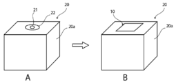
- the temporary sealing film of the present invention covers the electrolytic solution injection port after the electrolytic solution is injected from the electrolytic solution injection port provided in the outer body 20a of the can battery in the manufacture of the can battery. By sticking, the can battery is temporarily sealed, and after battery adjustment, the can battery is peeled off from the electrolyte solution inlet.
- the temporary sealing film of the present invention is attached to the periphery 22 of the electrolytic solution injection port so as to cover the opening 21 of the electrolytic solution injection port, whereby the electrolytic solution injection port is temporarily sealed.
- the surface layer 2 is stuck so as to be in direct contact with the periphery of the electrolytic solution injection port.
- the temporary sealing film of the present invention is less likely to remain around the electrolytic solution injection port after the temporary sealing film covering the electrolytic solution injection port is peeled off.
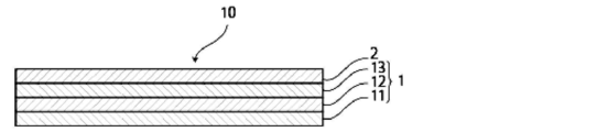
- the temporary sealing film of the present invention can be composed of a single layer or a plurality of layers, for example, as shown in FIGS.
- the temporary sealing film is comprised by the surface layer 2 (single layer), and the surface layer 2 contains polyolefin.
- any surface of the surface layer 2 may be attached so as to be in direct contact with the periphery of the electrolyte solution inlet.
- the temporary sealing film shown in FIGS. 2 to 4 includes a base material layer 1 and a surface layer 2.
- the base material layer 1 may be either a single layer or multiple layers (two or more layers).
- the base material layer 1 is composed of a single layer.
- the base material layer 1 is composed of two layers of a first base material layer 11 and a second base material layer 12.
- the base material layer 1 is composed of three layers of a first base material layer 11, a second base material layer 12, and a third base material layer 13.
- the number of layers is not particularly limited, but preferably about 2 or 3 layers.
- the surface layer 2 may be either a single layer or a multilayer, but the surface layer 2 is usually a single layer.
- the base material layer 1 and the surface layer 2 may be composed of the same resin.
- the base material layer 1 is a layer provided as necessary in order to exhibit the function of improving the barrier property and shape retention of the temporary sealing film.
- the temporary sealing film has the base material layer 1, it is possible to prevent moisture from entering from the outside during the adjustment of the can battery, and it is possible to suppress adverse effects on the electrolytic solution.
- the shape retention property of a temporary sealing film improves and the handleability at the time of sticking and peeling a temporary sealing film around an electrolyte solution injection port can be improved.
- the base material layer 1 can be made of, for example, metal or resin, and is preferably made of metal.
- the metal include an aluminum alloy, copper, and stainless steel.
- the base material layer 1 is metal foils, such as aluminum alloy foil, copper foil, and stainless steel foil.
- resin polyolefin, polyester, polyamide, epoxy resin, acrylic resin, fluorine resin, polyurethane, silicon resin, phenol resin, polyetherimide, polyimide, and a mixture or copolymer thereof. It can be composed of at least one resin such as a product.
- a rubber member having elasticity is used as a temporary sealing member in battery adjustment.
- the rubber member has a drawback of low barrier properties.
- barrier property becomes still better.
- the base material layer 1 is made of a metal, a metal foil is preferable in terms of cost, handleability, and light weight.
- the base material layer 1 is comprised with resin, it is preferable that it is a film, it is more preferable that it is a stretched film, and it is further more preferable that it is a biaxially stretched film.
- the substrate layer 1 may be formed of at least one of a metal vapor deposition film, an inorganic oxide vapor deposition film, a carbon-containing inorganic oxide vapor deposition film, and a resin film provided with these vapor deposition films, A resin coated film provided with a resin layer having a high barrier property such as vinylidene chloride can be used.
- a minimum Preferably it is about 10 micrometers or more. More preferably, it is about 15 ⁇ m or more, more preferably about 25 ⁇ m or more, particularly preferably about 27 ⁇ m or more, and the upper limit is preferably about 80 ⁇ m or less, more preferably about 50 ⁇ m or less, further preferably about 40 ⁇ m or less.
- Preferred ranges are about 10 to 80 ⁇ m, about 10 to 50 ⁇ m, about 10 to 40 ⁇ m, about 15 to 80 ⁇ m, about 15 to 50 ⁇ m, about 15 to 40 ⁇ m, about 25 to 80 ⁇ m, about 25 to 50 ⁇ m, and about 25 to 40 ⁇ m.
- each layer is preferably about 7 to 35 ⁇ m, more preferably about 7 to 20 ⁇ m, and further preferably about 9 to 18 ⁇ m from the same viewpoint. Can be mentioned.
- the temporary sealing film of the present invention may be composed only of the surface layer 2. That is, when the temporary sealing film of this invention is comprised by the single layer, the said layer exhibits the function as a surface layer.
- the surface layer 2 is provided on the base material layer 1, and is a layer provided with adhesiveness around the electrolyte solution inlet.
- the surface layer 2 is a layer that is in close contact with the outer casing 20a of the can battery and is peelable from the outer casing.
- the surface layer 2 has adhesiveness to such an extent that the temporary sealing film has “initial adhesion strength” and “adhesion strength after high-temperature storage” described later. Can be peeled off.
- the surface layer 2 is preferably a layer that can be peelably attached to the exterior body 20a so as to cover the electrolyte solution inlet of the exterior body 20a by at least one of heating and pressurization.
- the surface layer 2 contains polyolefin.
- the base material layer 1 and the surface layer 2 may be made of the same resin. In this case, it is preferable that both the base material layer 1 and the surface layer 2 of the temporary sealing film of the present invention contain polyolefin.
- the base material layer 1 may contain an elastomer exemplified by the surface layer 2 described later.
- the electrolyte inlet is preferably temporarily sealed during battery adjustment, and is excellent in resistance to electrolyte when exposed to a high-temperature environment.
- polyolefin is present on the surface of the surface layer 2.
- Examples of the polyolefin contained in the surface layer 2 include the following. In addition, it can confirm that the surface layer 2 contains polyolefin by infrared spectroscopy, for example.
- polyolefin examples include polyethylene such as very low density polyethylene (ultra low density polyethylene), low density polyethylene, medium density polyethylene, high density polyethylene, linear low density polyethylene; homopolypropylene, polypropylene block copolymer (eg, propylene) And ethylene block copolymer), polypropylene random copolymers (eg, propylene and ethylene random copolymers) and the like; ethylene-butene-propylene terpolymers, and the like.
- polyethylene and polypropylene are preferable, and polyethylene is more preferable.
- polyethylenes very low density polyethylene and low density polyethylene are preferable, and very low density polyethylene is particularly preferable.
- the extremely low density polyethylene is, for example, polyethylene having a specific gravity of about 0.9 or less, and the low density polyethylene is, for example, polyethylene having a specific gravity of about 0.91 to 0.93.
- the polypropylene a random copolymer of polypropylene is preferable.
- 50 mass% or more is mentioned normally.
- the polyolefin may be a cyclic polyolefin.
- the cyclic polyolefin is a copolymer of an olefin and a cyclic monomer.
- Examples of the olefin that is a constituent monomer of the cyclic polyolefin include ethylene, propylene, 4-methyl-1-pentene, butadiene, and isoprene.
- examples of the cyclic monomer that is a constituent monomer of the cyclic polyolefin include cyclic alkenes such as norbornene; specifically, cyclic dienes such as cyclopentadiene, dicyclopentadiene, cyclohexadiene, norbornadiene, and the like.
- cyclic alkene is preferable, and norbornene is more preferable.
- styrene is also mentioned as a monomer.
- the polyolefin may be an acid-modified polyolefin.
- the acid-modified polyolefin is a polymer modified by block polymerization or graft polymerization of polyolefin with carboxylic acid or carboxylic anhydride.
- carboxylic acid or carboxylic anhydride that modifies the polyolefin include maleic acid, acrylic acid, itaconic acid, crotonic acid, maleic anhydride, itaconic anhydride, and the like.
- Examples of the polyolefin to be modified include the above-mentioned polyolefins, and preferably polyethylene.
- the surface layer 2 preferably contains an acid-modified polyolefin.
- the polyolefin may be an acid-modified cyclic polyolefin.
- the acid-modified cyclic polyolefin is a copolymer obtained by copolymerizing a part of the monomer constituting the cyclic polyolefin in place of the ⁇ , ⁇ -unsaturated carboxylic acid or its anhydride, or ⁇ , ⁇ -unsaturated with respect to the cyclic polyolefin. It is a polymer obtained by block polymerization or graft polymerization of a saturated carboxylic acid or its anhydride.
- the cyclic polyolefin to be modified is the same as described above. Examples of the carboxylic acid or carboxylic acid anhydride used for modification include the same as those described above.
- polyethylene polyethylene, polypropylene, and acid-modified polyethylene are preferable.
- Polyolefin may be used individually by 1 type and may be used in combination of 2 or more types.
- the resin constituting the surface layer 2 preferably contains a polyolefin skeleton.
- the fact that the resin constituting the surface layer 2 contains a polyolefin skeleton can be analyzed by, for example, infrared spectroscopy, gas chromatography mass spectrometry, etc., and the analysis method is not particularly limited.
- infrared spectroscopy when measuring the infrared spectroscopy at a maleic anhydride-modified polyolefin, a peak derived from maleic acid is detected in the vicinity of the wave number of 1760 cm -1 and near the wave number 1780 cm -1.
- the peak may be small and may not be detected. In that case, it can be analyzed by nuclear magnetic resonance spectroscopy.
- the surface layer 2 may contain a resin other than polyolefin.
- the resin other than polyolefin include polyester, polyamide, epoxy resin, acrylic resin, fluorine resin, polyurethane, silicon resin, phenol resin, polyetherimide, polyimide, and mixtures and copolymers thereof.
- the ratio of the polyolefin contained in the surface layer 2 is not particularly limited, but is preferably 50% by mass or more, more preferably about 50 to 100% by mass, and further preferably about 60 to 100% by mass. Further, if the surface layer 2 further contains an elastomer described later, the ratio of the polyolefin is not particularly limited, but is preferably 50% by mass or more, more preferably about 50 to 90% by mass, and still more preferably 60%. About 90% by mass can be mentioned.
- Whether the surface layer 2 contains an elastomer can be determined, for example, by confirming that it has adhesiveness (tackiness) at room temperature.
- the surface layer 2 preferably has adhesiveness (tackiness).
- adhesiveness means a property of joining a plurality of objects, is a concept included in a broad sense, and means a property of sticking (tackiness).
- the surface of the surface layer 2 is preferably temporarily sealed at the electrolyte inlet during battery adjustment, has excellent resistance to electrolyte when exposed to a high temperature environment, and is preferably peeled off after battery adjustment. With characteristics. From such a viewpoint, the surface layer 2 preferably contains an elastomer in addition to the polyolefin.
- the acid-modified polyolefin is particularly preferably used together with an elastomer.
- the elastomer is not particularly limited as long as it is blended with polyolefin and exhibits adhesiveness.
- an elastomer (thermoplastic elastomer) composed of a thermoplastic resin is preferable.
- elastomer examples include styrene elastomers, olefin elastomers, acrylic elastomers, silicone elastomers, urethane elastomers, polyester elastomers, polyamide elastomers, and rubber elastomers.
- One type of elastomer may be used alone, or two or more types may be used in combination.
- styrenic elastomer is not particularly limited, but specific examples include styrene-butadiene-styrene block copolymer, styrene-isoprene-styrene block copolymer, styrene-ethylene-butylene-styrene block copolymer, and styrene-ethylene-propylene. -Styrene block copolymers and the like.
- olefin elastomer examples include copolymers of ⁇ -olefins having 2 to 20 carbon atoms such as ethylene, propylene, 1-butene, 1-hexene and 4-methyl-pentene.
- a copolymer of an ⁇ -olefin with a non-conjugated diene having 2 to 20 carbon atoms such as dicyclopentadiene, 1,4-hexadiene, cyclooctadiene, methylene norbornene, ethylidene norbornene, butadiene and isoprene.
- a carboxy-modified nitrile rubber obtained by copolymerizing methacrylic acid with a butadiene-acrylonitrile copolymer can be used.
- the acrylic elastomer has an acrylic ester as a main component, and specifically, ethyl acrylate, butyl acrylate, methoxyethyl acrylate, ethoxyethyl acrylate, and the like are preferably used. Moreover, glycidyl methacrylate, allyl glycidyl ether, etc. are used as a crosslinking point monomer. Furthermore, acrylonitrile and ethylene can be copolymerized.
- acrylonitrile-butyl acrylate copolymer examples include acrylonitrile-butyl acrylate copolymer, acrylonitrile-butyl acrylate-ethyl acrylate copolymer, acrylonitrile-butyl acrylate-glycidyl methacrylate copolymer, and the like.
- the silicone elastomer is mainly composed of organopolysiloxane, and examples thereof include polydimethylsiloxane, polymethylphenylsiloxane, and polydiphenylsiloxane elastomers.
- the urethane-based elastomer is composed of structural units of a hard segment composed of low molecular weight ethylene glycol and diisocyanate and a soft segment composed of a polymer (long chain) diol and diisocyanate.
- a polymer (long chain) diol polypropylene glycol, Polytetramethylene oxide, poly (1,4-butylene adipate), poly (ethylene-1,4-butylene adipate), polycaprolactone, poly (1,6-hexylene carbonate), poly (1,6-hexylene Neopentylene adipate) and the like.
- the polyester elastomer is obtained by polycondensation of dicarboxylic acid or its derivative and diol compound or its derivative.
- dicarboxylic acid include aromatic dicarboxylic acids such as terephthalic acid, isophthalic acid, and naphthalenedicarboxylic acid, and aromatic dicarboxylic acids in which hydrogen atoms of these aromatic nuclei are substituted with methyl groups, ethyl groups, phenyl groups, and the like, Examples thereof include aliphatic dicarboxylic acids having 2 to 20 carbon atoms such as adipic acid, sebacic acid and dodecanedicarboxylic acid, and alicyclic dicarboxylic acids such as cyclohexanedicarboxylic acid. These compounds can be used individually by 1 type or in mixture of 2 or more types.
- diol compound examples include aliphatic diols such as ethylene glycol, 1,3-propanediol, 1,4-butanediol, 1,6-hexanediol, 1,10-decanediol, and 1,4-cyclohexanediol.
- Bisphenol A bis- (4-hydroxyphenyl) -methane, bis- (4-hydroxy-3-methylphenyl) -propane, resorcin, and the like. These compounds can be used individually by 1 type or in mixture of 2 or more types.
- polyamide is a hard segment component, polybutadiene, butadiene-acrylonitrile copolymer, styrene-butadiene copolymer, polyisoprene, ethylene-propylene copolymer, polyether, polyester, polybutadiene, polycarbonate, polyacrylate, Examples thereof include block copolymers containing polymethacrylate, polyurethane, silicone rubber or the like as a soft segment component.
- Examples of rubber elastomers include polyisobutylene.
- the electrolyte inlet is preferably temporarily sealed, and is excellent in resistance to electrolyte when exposed to a high-temperature environment.
- Styrene elastomers and olefin elastomers are preferred, and olefin elastomers are particularly preferred.
- the ratio of the elastomer contained in the surface layer 2 is not particularly limited, but is preferably about 50% by mass or less, more preferably about 10 to 50% by mass, and still more preferably from the viewpoint of effectively improving the above-described characteristics. Is about 10 to 40% by mass.
- the thickness of the surface layer 2 is not particularly limited, but during the battery adjustment, the electrolyte inlet is preferably temporarily sealed, and is excellent in the resistance to electrolyte when exposed to a high temperature environment. Is preferably 3 ⁇ m or more, about 3 to 55 ⁇ m, about 3 to 35 ⁇ m, or about 3 to 25 ⁇ m from the viewpoint of suitably peeling.
- the surface layer 2 is an acid-modified polyethylene resin layer
- the base material layer 1 is an acid-modified polypropylene resin layer, a polyethylene naphthalate resin layer, and an acid-modified polypropylene resin layer.
- stacked in this order is mentioned.
- the acid-modified polypropylene resin layer contributes to the improvement of excellent electrolytic solution resistance and adhesion
- the polyethylene naphthalate resin layer contributes to the improvement of heat resistance, water vapor barrier property, airtightness, and electrolytic solution resistance.
- the modified polyethylene resin layer contributes to improvement in adhesion.
- the acid-modified polyethylene resin layer constituting the surface layer 2 preferably contains acid-modified polyethylene and the elastomer.
- the ratio of the elastomer contained in the surface layer 2 is also as described above.
- the thickness of the acid-modified polyethylene resin layer constituting the surface layer 2 is preferably about 10 to 50 ⁇ m, more preferably about 20 to 40 ⁇ m, and further preferably 25 to 35 ⁇ m.
- the thickness of the laminate constituting 1 is preferably about 30 to 100 ⁇ m, more preferably about 50 to 90 ⁇ m, and still more preferably about 70 to 80 ⁇ m.
- the surface layer 2 is an acid-modified polypropylene resin layer
- the base material layer 1 is an aluminum alloy foil and a polyethylene terephthalate resin layer in an order from the surface layer 2 side.
- stacked is mentioned.
- the polyethylene terephthalate resin layer contributes to improvement in heat resistance and electrolytic solution resistance
- the aluminum alloy foil contributes to improvement in water vapor barrier properties and airtightness
- the acid-modified polypropylene resin layer contributes to improvement in adhesion.
- the aluminum alloy foil preferably has a corrosion-resistant film on the surface in order to prevent dissolution and corrosion.
- the aluminum alloy foil may have a corrosion-resistant film on both sides.
- the corrosion-resistant film is, for example, a hydrothermal modification treatment such as boehmite treatment, a chemical conversion treatment, an anodizing treatment, a plating treatment such as nickel or chrome, and a corrosion prevention treatment for applying a coating agent.
- the treatment for forming the corrosion-resistant film one type may be performed, or two or more types may be combined. In addition to the single layer, a multi-layer structure can be used.
- the hydrothermal alteration treatment and the anodizing treatment are treatments in which the surface of the aluminum alloy foil is dissolved by a treating agent to form a metal compound having excellent corrosion resistance. Note that these processes may be included in the definition of the chemical conversion process.
- the aluminum alloy foil has a corrosion-resistant film
- the aluminum alloy foil including the corrosion-resistant film is used.
- Various types of corrosion-resistant films formed by chemical conversion treatment are known, and mainly at least one of phosphate, chromate, fluoride, triazine thiol compound, and rare earth oxide. Corrosion-resistant film containing
- the polyethylene terephthalate resin layer can be laminated with an aluminum alloy foil via an adhesive, for example.
- the adhesive is not particularly limited, and is a polyester such as polyethylene terephthalate, polybutylene terephthalate, polyethylene naphthalate, polybutylene naphthalate, polyethylene isophthalate, or copolyester; polyether; polyurethane (for example, polyester polyol as a main agent and , Epoxy resin; phenol resin; polyamide such as nylon 6, nylon 66, nylon 12, copolymerized polyamide; polyolefin, cyclic polyolefin, acid-modified polyolefin Polyolefin resins such as acid-modified cyclic polyolefins, polyvinyl acetate, cellulose, (meth) acrylic resins, polyimides, polycarbonates, urea resins, melamine trees Amino resins and the like; - chloroprene rubbers, nitrile rubbers,
- the thickness of the adhesive after curing includes about 1 to 10 ⁇ m, about 1 to 5 ⁇ m, about 2 to 10 ⁇ m, and about 2 to 5 ⁇ m.
- the acid-modified polypropylene resin layer constituting the surface layer 2 preferably contains acid-modified polypropylene and the elastomer.
- the ratio of the elastomer contained in the surface layer 2 is also as described above.
- the thickness of the acid-modified polypropylene resin layer constituting the surface layer 2 is preferably about 10 to 50 ⁇ m, more preferably about 20 to 40 ⁇ m, still more preferably 25 to 35 ⁇ m.
- the thickness of the laminate constituting 1 is preferably about 30 to 60 ⁇ m, more preferably about 40 to 55 ⁇ m.
- the side opposite to the side attached around the electrolyte inlet (if the temporary sealing film of the present invention has the base material layer 1 and the surface layer 2, A support may be laminated on the material layer 1 on the side opposite to the surface layer 2.
- a support that can be peeled off from the temporary sealing film when the temporary sealing film of the present invention is applied so as to cover the electrolyte injection hole can be used.
- the support include a film, paper, and non-woven fabric.
- the thickness of the support is not particularly limited, and can usually be about 10 to 100 ⁇ m.
- the surfaces on both sides of the support are preferably provided with releasability.
- the temporary sealing film of this invention is a winding body, it is preferable to provide a support body.
- the side opposite to the side attached around the electrolyte inlet (if the temporary sealing film of the present invention has the base material layer 1 and the surface layer 2, On the opposite side of the material layer 1 from the surface layer 2, an absorption layer capable of absorbing the electrolytic solution may be laminated.
- the absorption layer By providing the absorption layer, even when the electrolytic solution drops from the electrolytic solution injection nozzle and adheres to the temporary sealing film, the electrolytic solution flows out or scatters around the temporary sealing film. This can be suppressed.
- the absorbing layer include paper and nonwoven fabric.
- the side affixed around the electrolyte solution inlet (if the temporary sealing film of this invention has the base material layer 1 and the surface layer 2, the surface layer 2 A release film may be provided on the side opposite to the base material layer 1).
- the thickness of the temporary sealing film of the present invention is not particularly limited, but during battery adjustment, the electrolyte inlet is preferably temporarily sealed, and is excellent in resistance to electrolytic solution when exposed to a high temperature environment. Further, from the viewpoint of suitably peeling after the battery is adjusted, it is preferably about 25 ⁇ m or more, about 25 to 120 ⁇ m, about 30 to 120 ⁇ m, about 30 to 105 ⁇ m, or about 30 to 90 ⁇ m.
- the area of the temporary sealing film of the present invention is not particularly limited, and varies depending on the size of the can battery, but is usually 0.07 to 10 cm 2 from the viewpoint of being applied so as to cover the electrolyte solution inlet. Degree.
- the internal pressure of the can battery is usually about 0.2 to 0.4 MPa, and the size of the electrolyte injection port is generally about ⁇ 2 to 6 mm.
- the temporary sealing film of the present invention preferably has an initial adhesion strength measured under the following conditions of 2.0 N / 15 mm. As mentioned above, More preferably, it is 3.0 N / 15mm or more, More preferably, it is 5.0 N / 15mm or more. Preferred ranges of the initial adhesion strength are about 2.0 to 40.0 N / 15 mm, about 2.0 to 35.0 N / 15 mm, about 2.0 to 20.0 N / 15 mm, and 2.0 to 16.0 N.
- the shape of the temporary sealing film of the present invention is not particularly limited as long as the electrolyte injection port can be temporarily sealed, and various shapes as illustrated in FIG. Among the various shapes of temporary sealing films shown in FIGS. 7A to 7K, for example, temporary sealing as shown in the shapes shown in (a), (d), (g), and (k). Temporary sealing, such as shapes with protruding points that facilitate film peeling, and shapes shown in (b), (e), (f), (h), (i), and (j) A shape having corners that facilitate peeling of the film is preferable.
- ⁇ Measurement conditions for initial adhesion strength In the method for measuring the initial adhesion strength, first, the temporary sealing film is cut to produce a strip-shaped test piece having a width of 15 mm and a length of 50 mm. Next, under conditions of a temperature of 200 ° C. and a pressure of 1 MPa for 1 second, a test piece (a surface layer side in the case of having a base material layer and a surface layer) is placed on an aluminum plate (material is A3003, thickness is 1.5 mm). , The width is 25 mm and the length is 70 mm) (the portion to be bonded to the aluminum plate is the portion of the test piece having a length of 7 mm and a width of 15 mm).
- the end of the test piece that is not bonded to the aluminum plate and the aluminum plate are placed between the chucks using a tensile tester (for example, Tensilon Universal Tester RTG-1210, A & D Corporation).
- the initial adhesion strength is measured by pulling at a distance of 50 mm, a pulling speed of 300 mm / min, and a pulling angle of 180 °, and measuring the load at the time of peeling between the test piece and the aluminum plate.
- a tensile tester for example, Tensilon Universal Tester RTG-1210, A & D Corporation.
- the temporary sealing film of the present invention has the same value as the initial adhesion strength as the adhesion strength after high-temperature storage measured under the following conditions after being stored at 80 ° C. for 12 hours. Is preferred. That is, the temporary sealing film of the present invention has an adhesion strength after high-temperature storage measured under the following conditions, preferably 2.0 N / 15 mm or more, more preferably 3.0 N / 15 mm or more, and still more preferably 5. 0 N / 15 mm or more.
- Preferred ranges of the adhesion strength after the warm storage are about 2.0 to 40.0 N / 15 mm, about 2.0 to 20.0 N / 15 mm, about 2.0 to 16.0 N / 15 mm, and about 2.0 to About 10.0N / 15mm, about 3.0-40.0N / 15mm, about 3.0-20.0N / 15mm, about 3.0-16.0N / 15mm, about 3.0-10.0N / 15mm.
- about 5.0 to 40.0 N / 15 mm is particularly preferable.
- ⁇ Measurement conditions for adhesion strength after high-temperature storage In the method for measuring the adhesion strength after high-temperature storage, first, the temporary sealing film is cut to produce a strip-shaped test piece having a width of 15 mm and a length of 50 mm. Next, under conditions of a temperature of 200 ° C. and a pressure of 1 MPa for 1 second, a test piece (a surface layer side in the case of having a base material layer and a surface layer) is placed on an aluminum plate (material is A3003, thickness is 1.5 mm). , The width is 25 mm and the length is 70 mm) (the portion to be bonded to the aluminum plate is the portion of the test piece having a length of 7 mm and a width of 15 mm).
- the end of the test piece that is not bonded to the aluminum plate and the aluminum plate are placed between the chucks using a tensile tester (for example, Tensilon Universal Tester RTG-1210, A & D Corporation).
- the adhesion strength after high-temperature storage is measured by pulling at a distance of 50 mm, a pulling speed of 300 mm / min, and a pulling angle of 180 °, and measuring the load at the time of peeling between the test piece and the aluminum plate.
- a tensile tester for example, Tensilon Universal Tester RTG-1210, A & D Corporation.
- the adhesion strength after high-temperature storage is measured by pulling at a distance of 50 mm, a pulling speed of 300 mm / min, and a pulling angle of 180 °, and measuring the load at the time of peeling between the test piece and the aluminum plate.
- the shape of said test piece cannot be prepared due to circumstances such as a small sample, it is measured in a size that can be measured, and
- the temporary sealing film of the present invention is applied so as to cover the electrolytic solution injection port after the electrolytic solution is injected from the electrolytic solution injection port provided in the outer casing 20a of the can battery in the manufacture of the can battery, and thereafter It is a temporary sealing film peeled off.
- the temporary sealing film 10 of the present invention is formed around the electrolyte inlet 21 so as to cover the electrolyte inlet 21 of the can battery 20.
- the electrolyte injection port 21 is temporarily sealed.
- 6A and 6B are schematic cross-sectional views at this time.
- the diameter Wa of the opening of the electrolyte solution injection port 21 of the can battery 20 is not particularly limited and is usually about 2 to 6 mm, although it varies depending on the size of the can battery.
- the distance Wb from the end portion of the opening to the end portion around the electrolyte injection port (a peripheral portion, and at least the end portion is attached with a temporary sealing film) is particularly limited. However, although it depends on the size of the can battery, it is usually about 0.5 to 50 mm.
- surroundings of electrolyte solution injection hole may be lower than the outer side, and may have the shape in which the level
- the step t is not particularly limited and is usually about 0.1 to 10 mm, although it varies depending on the size of the can battery.
- one or more steps may exist in the portion to which the temporary sealing film of the present invention is attached.
- the temporary sealing film 10 of the present invention may be molded in advance and have a shape corresponding to the step t around the electrolyte injection port. Furthermore, at least a part of the temporary sealing film 10 of the present invention may be colored. Further, at least a part of the temporary sealing film 10 may be transparent. When the temporary sealing film 10 has a transparent part, when sticking the temporary sealing film 10 to an electrolyte solution injection port, alignment is easy and it becomes easy to carry out temporary sealing reliably.
- the electrolyte inlet is preferably temporarily sealed during battery adjustment, and is excellent in resistance to electrolyte when exposed to a high-temperature environment.
- the sealing film is preferably pasted so as to cover the electrolyte inlet by at least one of heating and pressurization, and more preferably pasted so as to cover the electrolyte inlet by both heating and pressurization.
- the heating temperature is preferably 110 ° C. or higher, more preferably about 110 to 130 ° C., and still more preferably about 120 to 130 ° C.
- the pressure applied at the time of application is preferably 1 MPa or more, more preferably about 1 to 3 MPa, and still more preferably about 2 to 3 MPa.
- the material around the electrolyte injection port of the outer package 20a to which the temporary sealing film of the present invention is attached is not particularly limited, and examples thereof include metals and plastics.
- the temporary sealing film of this invention is excellent also in the adhesiveness with respect to a metal, it can be used especially suitably with respect to the can battery using a metal case as the exterior body 20a.
- the exterior body 20a is mainly composed of a metal material, and the periphery of the electrolyte inlet of the exterior body 20a to which the temporary sealing film of the present invention is attached. Is also made of a metal material.
- the metal constituting the periphery of the electrolyte injection port is not particularly limited, but preferably includes an aluminum alloy, copper, stainless steel, and the like. Among these, an aluminum alloy is preferable. Examples of the aluminum alloy include those having a composition in which the alloy number defined by JIS is in the 3000s or 1000s.
- the surface roughness (Ra) around the electrolyte inlet is not particularly limited, but is preferably about 0.1 to 1.0 ⁇ m, more preferably 0.3 to 0. For example, about 5 ⁇ m.
- the surface roughness (Ra) is a value measured by the method defined in JIS B 0601: 2013.
- the can battery to which the temporary sealing film of the present invention is applied is not particularly limited as long as it uses an electrolytic solution, and may be either a primary battery or a secondary battery.
- the types of secondary batteries include lithium ion batteries, lead storage batteries, nickel / hydrogen storage batteries, nickel / cadmium storage batteries, nickel / iron storage batteries, nickel / zinc storage batteries, silver oxide / zinc storage batteries, polyvalent cation batteries, capacitors, A capacitor etc. are mentioned.
- a lithium ion battery is a suitable application target of the temporary sealing film of the present invention.
- the temporary sealing film of the present invention is used as follows, for example. That is, in the manufacture of a can battery, after the electrolyte solution is injected from the electrolyte solution inlet provided in the outer body of the can battery, the can battery is temporarily sealed by being pasted so as to cover the electrolyte solution inlet. . In this state, battery adjustments such as an aging process and an initial charging process are performed. For example, the aging condition is 40 to 150 ° C. and about 1 to 72 hours. After the battery adjustment is completed, the temporary sealing film of the present invention is peeled off from the periphery of the electrolytic solution injection port, and the electrolytic solution injection port is finally sealed with the present sealing member, whereby a can battery is manufactured.
- the main sealing by the main sealing member includes, for example, a method of laser welding the main sealing member to the electrolyte solution inlet.
- the method for producing the temporary sealing film of the present invention is not particularly limited, and a known method for producing a film can be employed.
- a manufacturing method of the temporary sealing film of this invention the method of manufacturing by extruding resin which comprises a temporary sealing film and shape
- the temporary sealing film of this invention has the base material layer 1 and the surface layer 2, the method of laminating
- the battery adjustment method of the present invention is the temporary adjustment of the present invention described in the section of “1. Temporary sealing film” after injecting the electrolyte from the electrolyte injection port provided in the outer casing of the can battery. A sealing film is used to temporarily seal the electrolyte solution inlet so as to cover it.
- the battery adjustment method of the present invention is a method of adjusting the battery after injecting the electrolyte from the electrolyte solution inlet of the can battery in the production of the can battery, and includes at least the following steps ( A), (B), and (C) are provided.
- the temporary sealing film of the present invention is prepared.
- the surface layer 2 of the temporary sealing film is pasted so as to cover the electrolytic solution injection port. Temporarily seal the inlet.
- battery adjustment is performed in a state where the electrolyte injection port is temporarily sealed with a temporary sealing film.
- the temporary sealing film is peeled off.
- the electrolyte injection port can be suitably temporarily sealed during battery adjustment, and the battery is excellent in resistance to electrolytic solution when exposed to a high temperature environment. It can peel suitably after adjustment. Examples of battery adjustment include an aging process and an initial charging process.
- a can battery is manufactured by finally sealing the electrolyte injection port with the sealing member.
- the method for manufacturing a can battery of the present invention is described in the section of “1. Temporary sealing film” after injecting an electrolyte from an electrolyte injection port provided in the outer casing 20a of the can battery.
- the temporary sealing film of the present invention is used to temporarily seal the electrolyte injection port so as to cover it.
- the method for producing a can battery according to the present invention includes at least the following steps (A), (B), (C), (D), and (E).
- the temporary sealing film of the present invention is prepared.
- the surface layer 2 of the temporary sealing film is pasted so as to cover the electrolytic solution injection port. Temporarily seal the inlet.
- battery adjustment is performed in a state where the electrolyte injection port is temporarily sealed with a temporary sealing film.
- the temporary sealing film is peeled off.
- the electrolyte injection port can be suitably temporarily sealed during battery adjustment, and the battery has excellent resistance to electrolytic solution when exposed to a high temperature environment. It can peel suitably after adjustment.
- a can battery is manufactured by peeling the temporary sealing film of this invention from the circumference
- the can battery of the present invention is a temporary seal according to the present invention so as to cover the electrolyte injection port after the electrolyte solution is injected from the electrolyte injection port provided in the outer casing of the can battery in the manufacture of the can battery.
- the film is temporarily sealed with a film, and the electrolyte solution inlet is provided with the temporary sealing film of the present invention.
- the can battery of the present invention is a can battery in which the electrolyte solution inlet provided in the outer casing of the can battery is temporarily sealed with the temporary sealing film of the present invention. Liquid is present.
- Example 1 The acid-modified polyethylene resin to which the olefin elastomer (addition amount 10% by mass) was added was extruded into a film to obtain a temporary sealing film (thickness 40 ⁇ m).
- Example 2 Extremely low density polyethylene was extruded into a film to obtain a temporary sealing film (thickness: 50 ⁇ m).
- Example 3 On one side of an aluminum alloy foil (JIS H4160: 1994 A8021HO) subjected to chemical conversion treatment on both sides, an acid-modified polyethylene resin added with an olefin-based elastomer (added amount 10 mass%) is melt-extruded to obtain an aluminum alloy foil ( A temporary sealing film composed of a base material layer, thickness 35 ⁇ m) / acid-modified polyethylene resin layer (surface layer, thickness 40 ⁇ m) to which an olefin elastomer was added was obtained.
- the chemical conversion treatment of the aluminum alloy foil is performed using a roll coating method in which a treatment liquid composed of a phenol resin, a chromium fluoride compound, and phosphoric acid is applied so that the chromium coating amount is 10 mg / m 2 (dry weight).
- the coating was performed on both sides of the foil and baked under conditions where the coating temperature was 180 ° C or higher.
- Example 4 On one side of the aluminum alloy foil (JIS H4160: 1994 A8021HO) having the above-mentioned corrosion-resistant film formed on both sides, a very low density polyethylene is melt-extruded to obtain an aluminum alloy foil (base material layer, thickness 40 ⁇ m) / pole A temporary sealing film composed of low density polyethylene (surface layer, thickness 50 ⁇ m) was obtained.
- Example 5 The acid-modified polyethylene resin used in Example 1 was melt-extruded on one surface of a base material layer in which an acid-modified polypropylene resin, a polyethylene naphthalate resin, and an acid-modified polypropylene resin were sequentially laminated, and an acid-modified polypropylene resin layer (base Material layer, 30 ⁇ m) / polyethylene naphthalate (base layer, 12 ⁇ m) resin layer / acid-modified polypropylene (base layer, 30 ⁇ m) resin layer / acid-modified polyethylene resin layer (surface layer, thickness 33 ⁇ m) A sealing film was obtained.
- Example 6 On one side of the aluminum alloy foil (JIS H4160: 1994 A8021HO) having the above-mentioned corrosion-resistant film formed on both sides, an acid-modified polypropylene resin to which an olefin-based elastomer is added (added amount of 10% by mass) is melt-extruded.
- a polyethylene terephthalate film (thickness: 12 ⁇ m) is attached to the surface, and an adhesive (thickness after curing: 3 ⁇ m, polyester polyol as a main agent: aromatic isocyanate compound as a curing agent: ethyl acetate as a solvent in a mass ratio of 15: 3: 13
- an acid-modified polypropylene resin layer (surface layer, thickness 30 ⁇ m) / aluminum alloy foil (base material layer, thickness 35 ⁇ m) / adhesive (base) Material layer, thickness 3 ⁇ m) / polyethylene terephthalate (base layer, thickness 12 ⁇ m)
- Comparative Example 1 On one side of the aluminum alloy foil (JIS H4160: 1994 A8021HO) having the above-mentioned corrosion-resistant film formed on both sides, a slightly tacky acrylic acid-vinyl acetate copolymer resin is melt-extruded to obtain an aluminum alloy foil (base A temporary sealing film composed of a material layer (thickness 40 ⁇ m) / acrylic acid-vinyl acetate copolymer resin (surface layer, thickness 5 ⁇ m) was obtained.
- Comparative Example 2 A highly adhesive acrylic acid-vinyl acetate copolymer resin is melt-extruded on one surface of an aluminum alloy foil (JIS H4160: 1994 A8021HO) having the above-mentioned corrosion-resistant film formed on both sides, and an aluminum alloy foil (base A temporary sealing film composed of a material layer (thickness 40 ⁇ m) / acrylic acid-vinyl acetate copolymer resin (surface layer, thickness 5 ⁇ m) was obtained.
- Comparative Example 3 A mixed resin of an adhesive acrylic acid-vinyl acetate copolymer resin and an isocyanate curing agent is applied to one surface of an aluminum alloy foil (JIS H4160: 1994 A8021HO) having the above-mentioned corrosion-resistant film formed on both surfaces.
- a temporary sealing film composed of a cured product of aluminum alloy foil (base layer, thickness 40 ⁇ m) / acrylic acid-vinyl acetate copolymer resin (surface layer, thickness 5 ⁇ m) was obtained.
- each temporary sealing film was cut to produce a strip-shaped test piece having a width of 15 mm and a length of 50 mm.
- a test piece (a surface layer side in the case of having a base material layer and a surface layer) is placed on an aluminum plate (material is A3003, thickness is 1.5 mm).
- the width was 25 mm and the length was 70 mm) (the portion to be bonded to the aluminum plate was a portion having a test piece length of 7 mm and a width of 15 mm).
- the end of the test piece that is not bonded to the aluminum plate and the aluminum plate are used to measure a distance between chucks of 50 mm using a tensile tester (A & D Corporation, Tensilon Universal Tester RTG-1210).
- the initial adhesion strength was measured by pulling at a pulling speed of 300 mm / min and a pulling angle of 180 ° and measuring the load at the time of peeling between the test piece and the aluminum plate.
- the initial adhesion strength was an average value measured three times.
- each temporary sealing film was cut to produce a strip-shaped test piece having a width of 15 mm and a length of 50 mm.
- a test piece (a surface layer side in the case of having a base material layer and a surface layer) is placed on an aluminum plate (material is A3003, thickness is 1.5 mm).
- the width was 25 mm and the length was 70 mm) (the portion to be bonded to the aluminum plate was a portion having a test piece length of 7 mm and a width of 15 mm).
- it was stored for 12 hours in an environment at a temperature of 80 ° C.
- the end of the test piece that is not bonded to the aluminum plate and the aluminum plate are used to measure a distance between chucks of 50 mm using a tensile tester (A & D Corporation, Tensilon Universal Tester RTG-1210).
- the adhesion strength after high-temperature storage was measured by pulling at a pulling speed of 300 mm / min and a pulling angle of 180 ° and measuring the load at the time of peeling between the test piece and the aluminum plate.
- the adhesion strength was an average value measured three times.
- the temporary sealing film When the temporary sealing film has a surface layer and a base material layer, the surface layer and the base material layer are not peeled off. Practical level as a temporary sealing film.
- C The temporary sealing film is dissolved. When the temporary sealing film has a surface layer and a base material layer, the surface layer is dissolved or the surface layer and the base material layer are peeled off. Unusable as a temporary sealing film.
- PPa means acid-modified polypropylene
- PEN polyethylene naphthalate
- PET means polyethylene terephthalate
- the electrolyte inlet is preferably temporarily sealed during battery adjustment. I can see that it can be stopped.
- the temporary sealing films of Examples 1 to 6 were stored at a high temperature in a state of being attached to an aluminum plate and then peeled off, the temporary sealing film did not remain on the surface of the aluminum plate, and the peelability It turns out that it is excellent in. Furthermore, it turns out that it is excellent in the electrolyte solution resistance when exposed to a high temperature environment.
- the temporary sealing films of Examples 3 to 6 are provided with the base material layer, they have a high shape retaining property and are particularly excellent in handleability when pasted to the electrolyte solution inlet and then peeled off. It was.
Landscapes
- Chemical & Material Sciences (AREA)
- Chemical Kinetics & Catalysis (AREA)
- Electrochemistry (AREA)
- General Chemical & Material Sciences (AREA)
- Filling, Topping-Up Batteries (AREA)
- Sealing Battery Cases Or Jackets (AREA)
Abstract
本発明の仮封止フィルムは、缶電池の製造において、前記缶電池の電解液注入口から電解液が注入された後、前記電解液注入口を覆うように貼付され、その後に剥離される用途に供される仮封止フィルムであって、前記仮封止フィルムは、表面層を備えており、前記表面層は、ポリオレフィンを含んでいる。
Description
本発明は、仮封止フィルム、電池調整方法、及び缶電池の製造方法に関する。
近年、リチウムイオン電池などの缶電池が、電気自動車、ハイブリッド電気自動車、パソコン、カメラ、携帯電話等の様々な用途に広く使用されている。このような缶電池を製造する際には、缶電池の外装体に設けられた電解液注入口から電解液が注入された後、電解液注入口が封止部材によって封止される。
このような缶電池の製造過程において、缶電池の外装体(外装容器)に設けられた電解液注入口から電解液を注入した後、エージング工程、初期充電工程などの電池調整が行われる。電池調整において、電解液注入口が開口した状態で電池調整を行うと、電解液注入口から電解液がこぼれるおそれがある。また、電池調整においては、ガスが発生する。このため、電池調整において、電解液注入口を仮封止部材で仮封止し、電池調整後に仮封止部材を取り除いて電解液注入口からガスを放出させ、その後に、電解液注入口を封止部材で本封止する必要がある(特許文献1を参照)。
従来、電池調整における仮封止部材としては、弾性を有するゴム部材(例えばゴム栓)が使用されているが、弾性による仮封止では、封止されたことの管理が難しいという問題がある。
そこで、本発明者らは、特許文献1のように、樹脂シートを仮封止部材として用いることを検討した。具体的には、本発明者らは、高い粘着力を有するものが存在していることから、アクリル樹脂等の粘着剤を用いた粘着フィルムを仮封止フィルムとして用いることを検討した。
エージング工程、初期充電工程などの電池調整では、缶電池が高温になることがある。このため、粘着フィルムを仮封止フィルムとして用いる場合には、仮封止フィルムに電解液が付着した後に高温環境下に晒された場合の耐電解液性に優れていることが求められる。ところが、アクリル樹脂等の粘着剤は、電解液が付着して、高温環境に晒されると、電解液によって溶解したり、密着性が低下して電解液注入口から脱落するなど、耐電解液性が不十分であることが明らかとなった。
また、缶電池の製造において、電池調整の後、仮封止フィルムは好適に剥離されることが求められる。ところが、アクリル樹脂等の粘着剤を用いた粘着フィルムにおいて、例えば粘着力の高いものを使用すると、初期密着性には優れているものの、電池調整後に剥離した後に、電解液注入口の周囲に粘着剤成分が残存し、その後の本封止部材による電解液注入口の本封止が阻害される場合があることを見出した。
電解液注入口の周囲に残存した粘着成分による本封止の阻害の問題について、例えば特許文献1のように、仮封止部材を封着した位置とは異なる位置にて注入口の周囲に本封止部材を封着すれば、解消されると考えられる。しかしながら、仮封止部材と本封止部材の位置が異なるように設計すると、缶電池の製造プロセスの制約が大きくなるため、実際の缶電池製造では採用し難い。
このような状況下、本発明は、缶電池の製造において、缶電池の電解液注入口から電解液が注入された後、前記電解液注入口を覆うように貼付され、その後に剥離される用途に供される仮封止フィルムであって、電池調整の間、電解液注入口を好適に仮封止することができ、高温環境下に晒された場合の耐電解液性に優れるとともに、電池調整後に好適に剥離することができる(すなわち、電池調整後、電解液注入口を覆う仮封止フィルムを剥離した後に、仮封止フィルムの一部が電解液注入口の周囲に残存し難く、電解液注入口から好適に剥離することができる)仮封止フィルムを提供することを主な目的とする。
本発明者らは、前記課題を解決すべく鋭意検討を行った。その結果、ポリオレフィンを含んでいる表面層を備えている仮封止フィルムは、電池調整の間、缶電池の外装体に設けられた電解液注入口を好適に仮封止することができ、高温環境下に晒された場合の耐電解液性に優れるとともに、電池調整後に好適に剥離できることを見出した。本発明は、これらの知見に基づいて、更に検討を重ねることにより完成したものである。
即ち、本発明は、下記に掲げる態様の発明を提供する。
項1. 缶電池の製造において、前記缶電池の外装体に設けられた電解液注入口から電解液が注入された後、前記電解液注入口を覆うように貼付され、その後に剥離される用途に供される仮封止フィルムであって、
前記仮封止フィルムは、表面層を備えており、
前記表面層は、ポリオレフィンを含んでいる、仮封止フィルム。
項2. 前記表面層を赤外分光法で分析すると、無水マレイン酸に由来するピークが検出される、項1に記載の仮封止フィルム。
項3. 前記表面層は、エラストマーをさらに含んでいる、項1または2に記載の仮封止フィルム。
項4. 前記表面層を構成している樹脂は、ポリオレフィン骨格を有している、項1~3のいずれかに記載の仮封止フィルム。
項5. 前記ポリオレフィンが、酸変性ポリオレフィン及び極低密度ポリエチレンの少なくとも一方を含んでいる、項1~4のいずれかに記載の仮封止フィルム。
項6. 前記仮封止フィルムは、さらに基材層を備えている、項1~5のいずれかに記載の仮封止フィルム。
項7. 前記基材層が、金属箔により構成されている、項6に記載の仮封止フィルム。
項8. 前記表面層が酸変性ポリエチレン樹脂層であり、前記基材層が、酸変性ポリプロピレン樹脂層、ポリエチレンナフタレート樹脂層、及び酸変性ポリプロピレン樹脂層がこの順に積層された積層体により構成されている、項6に記載の仮封止フィルム。
項9. 前記表面層が酸変性ポリプロピレン樹脂層であり、前記基材層が、前記表面層側から順にアルミニウム合金箔及びポリエチレンテレフタレート樹脂層が積層された積層体により構成されている、項6に記載の仮封止フィルム。
項10. 加熱及び加圧の少なくとも一方により、前記電解液注入口を覆うように貼付される、項1~9のいずれかに記載の仮封止フィルム。
項11. 前記表面層は、加熱及び加圧の少なくとも一方により、前記電解液注入口を覆うように、前記外装体に対して剥離可能に貼付することができる、項1~10のいずれかに記載の仮封止フィルム。
項12. 缶電池の製造において、前記缶電池の電解液注入口から電解液を注入した後、電池調整を行う方法であって、
少なくとも、以下の工程(A)、(B)、及び(C)を備える、電池調整方法。
工程(A):ポリオレフィンを含んでいる表面層を備えている仮封止フィルムを用意する。
工程(B):缶電池の製造において、前記缶電池の電解液注入口から電解液が注入された後、前記電解液注入口を覆うように前記仮封止フィルムの前記表面層を貼付して前記電解液注入口を仮封止する。
工程(C):前記電解液注入口を前記仮封止フィルムで仮封止した状態で電池調整を行う。
項13. 缶電池の製造方法であって、少なくとも、以下の工程(A)、(B)、(C)、(D)、及び(E)を備える、缶電池の製造方法。
工程(A):ポリオレフィンを含んでいる表面層を備えている仮封止フィルムを用意する。
工程(B):缶電池の製造において、前記缶電池の外装体に設けられた電解液注入口から電解液が注入された後、前記電解液注入口を覆うように前記仮封止フィルムの前記表面層を貼付して前記電解液注入口を仮封止する。
工程(C):前記電解液注入口を前記仮封止フィルムで仮封止した状態で電池調整を行う。
工程(D):前記仮封止フィルムを剥離する。
工程(E):前記電解液注入口を本封止する。
項14. 前記工程(B)において、加熱及び加圧の少なくとも一方により、前記電解液注入口を覆うように前記仮封止フィルムの前記表面層を貼付して前記電解液注入口を仮封止する、項13に記載の缶電池の製造方法。
項15. 前記工程(C)の後、前記電解液注入口から、前記仮封止フィルムを剥離する工程をさらに備える、項13または14に記載の缶電池の製造方法。
項16. 缶電池の製造において、前記缶電池の外装体に設けられた電解液注入口から電解液を注入した後、電池調整を行う方法であって、
少なくとも、以下の工程(A)、(B)、及び(C)を備える、電池調整方法。
工程(A):ポリオレフィンを含んでいる表面層を備えている仮封止フィルムを用意する。
工程(B):缶電池の製造において、前記缶電池の電解液注入口から電解液が注入された後、前記電解液注入口を覆うように前記仮封止フィルムの前記表面層を貼付して前記電解液注入口を仮封止する。
工程(C):前記電解液注入口を前記仮封止フィルムで仮封止した状態で電池調整を行う。
項17. 缶電池の製造において、前記缶電池の外装体に設けられた電解液注入口から電解液が注入された後、前記電解液注入口を覆うように、項1~11のいずれかに記載の仮封止フィルムで仮封止され、前記電解液注入口に前記仮封止フィルムを備えた、缶電池。
項18.ポリオレフィンを含んでいる表面層を備えており、
前記表面層は、加熱及び加圧の少なくとも一方により、電解液注入口を覆うように、缶電池の外装体に対して剥離可能に貼付することができる、仮封止フィルム。
本発明によれば、缶電池の製造において、缶電池の外装体に設けられた電解液注入口から電解液が注入された後、前記電解液注入口を覆うように貼付され、その後に剥離される用途に供される仮封止フィルムであって、電池調整の間、電解液注入口を好適に仮封止することができ、高温環境下に晒された場合の耐電解液性に優れるとともに、電池調整後に好適に剥離することができる(すなわち、電池調整後、電解液注入口を覆う仮封止フィルムを剥離した後に、仮封止フィルムの一部が電解液注入口の周囲に残存し難く、好適に剥離することができる)仮封止フィルムを提供することができる。本発明の仮封止フィルムは、缶電池の製造において、缶電池の調整中に仮封止フィルムを剥離し、缶電池のガス抜きなどを行い、再度、仮封止フィルムで仮封止する態様で使用することもできる。
また、本発明によれば、缶電池の製造において、缶電池の外装体に設けられた電解液注入口から電解液が注入された後、電解液注入口を覆うように当該仮封止フィルムを貼付し、電解液注入口を仮封止して電池調整を行う方法を提供することができる。
また、本発明によれば、缶電池の製造において、缶電池の外装体に設けられた電解液注入口から電解液が注入された後、電解液注入口を覆うように当該仮封止フィルムを貼付し、電解液注入口を仮封止して電池調整を行い、その後に仮封止フィルムを剥離し、電解液注入口を本封止する、缶電池の製造方法を提供することができる。
本発明の仮封止フィルムは、缶電池の製造において、缶電池の外装体に設けられた電解液注入口から電解液が注入された後、電解液注入口を覆うように貼付され、その後に剥離される用途に供される仮封止フィルムである。本発明の仮封止フィルムは、表面層を備えており、前記表面層はポリオレフィンを含んでいることを特徴とする。以下、本発明の仮封止フィルムについて、さらに、当該仮封止フィルムを用いる電池調整方法、及び缶電池の製造方法について、詳述する。
なお、本明細書において、「~」で示される数値範囲は「以上」、「以下」を意味する。例えば、2~15mmとの表記は、2mm以上15mm以下を意味する。
1.仮封止フィルム
本発明の仮封止フィルムは、缶電池の製造において、缶電池の外装体20aに設けられた電解液注入口から電解液が注入された後、電解液注入口を覆うように貼付されることで缶電池を仮封止し、電池調整後に、電解液注入口から剥離されるものである。本発明の仮封止フィルムが電解液注入口の開口部21を覆うようにして電解液注入口の周囲22に貼付されることで、電解液注入口が仮封止される。本発明の仮封止フィルムによって電解液注入口を仮封止する際には、表面層2が電解液注入口の周囲に直接接触するように貼付される。
本発明の仮封止フィルムは、缶電池の製造において、缶電池の外装体20aに設けられた電解液注入口から電解液が注入された後、電解液注入口を覆うように貼付されることで缶電池を仮封止し、電池調整後に、電解液注入口から剥離されるものである。本発明の仮封止フィルムが電解液注入口の開口部21を覆うようにして電解液注入口の周囲22に貼付されることで、電解液注入口が仮封止される。本発明の仮封止フィルムによって電解液注入口を仮封止する際には、表面層2が電解液注入口の周囲に直接接触するように貼付される。
前記の通り、本発明の仮封止フィルムは、電池調整後、電解液注入口を覆う仮封止フィルムを剥離した後に、仮封止フィルムの一部が電解液注入口の周囲に残存し難く、好適に剥離することができる。すなわち、本発明の仮封止フィルムと缶電池の外装体との界面で、仮封止フィルムが外装体から好適に剥離する。
本発明の仮封止フィルムは、例えば、図1~4に示されるように、単層または複数層により構成することができる。例えば、図1においては、仮封止フィルムは表面層2(単層)により構成されており、表面層2にポリオレフィンが含まれている。仮封止フィルムが表面層2の単層により構成されている場合には、表面層2の何れの面が電解液注入口の周囲に直接接触するように貼付されてもよい。また、図2~図4に示す仮封止フィルムは、基材層1及び表面層2を備えている。基材層1は、単層及び複層(2層以上)のいずれであってもよい。例えば、図2において、基材層1は単層により構成されている。また、図3において、基材層1は、第1の基材層11及び第2の基材層12の2層により構成されている。また、図4において、基材層1は、第1の基材層11、第2の基材層12及び第3の基材層13の3層により構成されている。基材層1が複層である場合、その層数については特に制限されないが、好ましくは2層又は3層程度が挙げられる。また、表面層2についても、単層及び複層のいずれであってもよいが、表面層2は、通常、単層とすればよい。
また、後述の通り、本発明の仮封止フィルムにおいて、基材層1と表面層2とは、同じ樹脂により構成されていてもよい。
基材層1は、仮封止フィルムのバリア性や保形性を高める機能を発揮するために、必要に応じて設けられる層である。仮封止フィルムが基材層1を有することにより、缶電池の調整時に外部から水分が入ることを抑制することができ、電解液への悪影響を抑制することができる。また、仮封止フィルムの保形性が向上し、仮封止フィルムを電解液注入口の周囲に貼付及び剥離する際の取扱性を向上させることができる。
基材層1は、例えば、金属または樹脂により構成することができ、金属により構成されていることが好ましい。金属としては、例えば、アルミニウム合金、銅、ステンレス鋼などが挙げられる。基材層1が金属により構成される場合、基材層1は、アルミニウム合金箔、銅箔、ステンレス鋼箔などの金属箔であることが好ましい。また、基材層1が樹脂により構成される場合、ポリオレフィン、ポリエステル、ポリアミド、エポキシ樹脂、アクリル樹脂、フッ素樹脂、ポリウレタン、珪素樹脂、フェノール樹脂、ポリエーテルイミド、ポリイミド、及びこれらの混合物や共重合物等の少なくとも1種の樹脂によって構成することができる。前記の通り、従来、電池調整における仮封止部材としては、弾性を有するゴム部材が使用されているが、ゴム部材はバリア性が低いという欠点がある。これに対して、本発明の仮封止フィルムが基材層1を有する場合には、バリア性がさらに良好となる。
基材層1が金属により構成されている場合、金属箔は、コスト、取扱性、軽量であることなどの点で好ましい。基材層1が樹脂により構成されている場合、フィルムであることが好ましく、延伸フィルムであることがより好ましく、2軸延伸フィルムであることがさらに好ましい。また、基材層1としては、金属蒸着膜、無機酸化物蒸着膜、炭素含有無機酸化物蒸着膜、及びこれらの蒸着膜を設けた樹脂フィルムのうち、少なくとも1種により形成することや、ポリ塩化ビニリデンなどのバリア性の高い樹脂層を設けた樹脂コートフィルムなどを用いることができる。
基材層1の厚みとしては、特に制限されないが、仮封止フィルムを電解液注入口の周囲に貼付及び剥離する際の取扱性を向上させる観点からは、下限については、好ましくは約10μm以上、より好ましくは約15μm以上、さらに好ましくは約25μm以上、特に好ましくは約27μm以上が挙げられ、上限については、好ましくは約80μm以下、より好ましくは約50μm以下、さらに好ましくは約40μm以下が挙げられ、好ましい範囲としては、10~80μm程度、10~50μm程度、10~40μm程度、15~80μm程度、15~50μm程度、15~40μm程度、25~80μm程度、25~50μm程度、25~40μm程度、27~80μm程度、27~50μm程度、27~40μm程度が挙げられる。
なお、基材層1が複層により構成されている場合、各層の厚みとしては、同様の観点から、好ましくは7~35μm程度、より好ましくは7~20μm程度、さらに好ましくは9~18μm程度が挙げられる。
本発明の仮封止フィルムは、表面層2のみにより構成されていてもよい。すなわち、本発明の仮封止フィルムが単層により構成されている場合、当該層が、表面層としての機能を発揮する。
また、本発明の仮封止フィルムが基材層1を有する場合、表面層2は、基材層1の上に設けられており、電解液注入口の周囲に密着性を備える層である。本発明の仮封止フィルムにおいて、表面層2は、缶電池の外装体20aに密着し、かつ、外装体から剥離可能な層である。好ましくは、表面層2は、仮封止フィルムが後述の「初期密着強度」及び「高温保管後の密着強度」を備える程度に密着性を備えており、当該密着強度であれば、外装体20aから剥離が可能である。また、表面層2は、好ましくは、加熱及び加圧の少なくとも一方により、外装体20aの電解液注入口を覆うように、外装体20aに対して剥離可能に貼付することができる層である。
本発明において、表面層2は、ポリオレフィンを含んでいる。
また、本発明の仮封止フィルムにおいて、基材層1と表面層2とは、同じ樹脂により構成されていてもよい。この場合、本発明の仮封止フィルムの基材層1及び表面層2が、共にポリオレフィンを含んでいることが好ましい。基材層1には、後述の表面層2で例示するエラストマーが含まれていてもよい。
電池調整の間、電解液注入口を好適に仮封止し、高温環境下に晒された場合の耐電解液性に優れ、さらに電池調整後には好適に剥離される観点から、本発明の仮封止フィルムにおいては、表面層2の表面に、ポリオレフィンが存在していることが好ましい。
表面層2に含まれるポリオレフィンとしては、下記のものが例示される。なお、表面層2がポリオレフィンを含んでいることは、例えば赤外分光法によって確認することができる。
ポリオレフィンの具体例としては、極低密度ポリエチレン(超低密度ポリエチレン)、低密度ポリエチレン、中密度ポリエチレン、高密度ポリエチレン、線状低密度ポリエチレン等のポリエチレン;ホモポリプロピレン、ポリプロピレンのブロックコポリマー(例えば、プロピレンとエチレンのブロックコポリマー)、ポリプロピレンのランダムコポリマー(例えば、プロピレンとエチレンのランダムコポリマー)等のポリプロピレン;エチレン-ブテン-プロピレンのターポリマー等が挙げられる。これらのポリオレフィンの中でも、好ましくはポリエチレン及びポリプロピレン、より好ましくはポリエチレンが挙げられる。ポリエチレンの中でも、極低密度ポリエチレン及び低密度ポリエチレンが好ましく、特に、極低密度ポリエチレンが好ましい。なお、極低密度ポリエチレンとは、例えば比重0.9以下程度であるポリエチレンであり、低密度ポリエチレンとは、例えば比重0.91程度から0.93程度であるポリエチレンである。また、ポリプロピレンとしては、ポリプロピレンのランダムコポリマーが好ましい。なお、ポリプロピレンに含まれるプロピレン単位の割合としては、通常、50質量%以上が挙げられる。
また、ポリオレフィンは、環状ポリオレフィンであってもよい。環状ポリオレフィンは、オレフィンと環状モノマーとの共重合体であり、環状ポリオレフィンの構成モノマーであるオレフィンとしては、例えば、エチレン、プロピレン、4-メチル-1-ペンテン、ブタジエン、イソプレン等が挙げられる。また、環状ポリオレフィンの構成モノマーである環状モノマーとしては、例えば、ノルボルネン等の環状アルケン;具体的には、シクロペンタジエン、ジシクロペンタジエン、シクロヘキサジエン、ノルボルナジエン等の環状ジエン等が挙げられる。これらのポリオレフィンの中でも、好ましくは環状アルケン、更に好ましくはノルボルネンが挙げられる。また、モノマーとしては、スチレンも挙げられる。
ポリオレフィンは、酸変性ポリオレフィンであってもよい。酸変性ポリオレフィンとは、ポリオレフィンをカルボン酸またはカルボン酸無水物でブロック重合又はグラフト重合することにより変性したポリマーである。ポリオレフィンを変性するカルボン酸またはカルボン酸無水物としては、例えば、マレイン酸、アクリル酸、イタコン酸、クロトン酸、無水マレイン酸、無水イタコン酸等が挙げられる。また、変性されるポリオレフィンとしては、前述のポリオレフィンが挙げられ、好ましくはポリエチレンが挙げられる。表面層2は、酸変性ポリオレフィンを含むことが好ましい。
ポリオレフィンは、酸変性環状ポリオレフィンであってもよい。酸変性環状ポリオレフィンとは、環状ポリオレフィンを構成するモノマーの一部を、α,β-不飽和カルボン酸又はその無水物に代えて共重合することにより、或いは環状ポリオレフィンに対してα,β-不飽和カルボン酸又はその無水物をブロック重合又はグラフト重合することにより得られるポリマーである。変性される環状ポリオレフィンについては、前記と同様である。また、変性に使用されるカルボン酸またはカルボン酸無水物としては、前述のものと同様のものが挙げられる。
ポリオレフィンの中でも、好ましくはポリエチレン、ポリプロピレン、酸変性ポリエチレンが挙げられる。ポリオレフィンは、1種類単独で使用してもよいし、2種類以上を組み合わせて使用してもよい。
表面層2を構成している樹脂は、ポリオレフィン骨格を含んでいることが好ましい。表面層2を構成している樹脂がポリオレフィン骨格を含むことは、例えば、赤外分光法、ガスクロマトグラフィー質量分析法などにより分析可能であり、分析方法は特に問わない。例えば、赤外分光法にて無水マレイン酸変性ポリオレフィンを測定すると、波数1760cm-1付近と波数1780cm-1付近に無水マレイン酸由来のピークが検出される。ただし、酸変性度が低いとピークが小さくなり検出されない場合がある。その場合は核磁気共鳴分光法にて分析可能である。
表面層2は、ポリオレフィン以外の樹脂を含んでいてもよい。ポリオレフィン以外の樹脂としては、例えば、ポリエステル、ポリアミド、エポキシ樹脂、アクリル樹脂、フッ素樹脂、ポリウレタン、珪素樹脂、フェノール樹脂、ポリエーテルイミド、ポリイミド、及びこれらの混合物や共重合物等が挙げられる。
表面層2に含まれるポリオレフィンの割合としては、特に制限されないが、好ましくは50質量%以上、より好ましくは50~100質量%程度、さらに好ましくは60~100質量%程度が挙げられる。また、表面層2にさらに後述のエラストマーが含まれる場合であれば、ポリオレフィンの割合としては、特に制限されないが、好ましくは50質量%以上、より好ましくは50~90質量%程度、さらに好ましくは60~90質量%程度が挙げられる。
表面層2がエラストマーを含むことは、例えば、常温で粘着性(タック性)を有することの確認によって判断することができる。
表面層2は、粘着性(タック性)を備えていることが好ましい。表面層2が粘着性を備えることで、本発明の保護フィルムの位置決めが容易になる。なお、本発明において、粘着又は粘着性とは、複数の物体同士を接合する性質を意味し、広義の接着に含まれる概念であり、粘り着く性質(タック性)を意味している。
表面層2の表面は、電池調整の間、電解液注入口を好適に仮封止し、高温環境下に晒された場合の耐電解液性に優れ、さらに電池調整後には好適に剥離される特性を備える。このような観点から、表面層2は、ポリオレフィンに加えて、エラストマーを含んでいることが好ましい。また、酸変性ポリオレフィンは、エラストマーと共に用いられることが特に好ましい。
エラストマーとしては、ポリオレフィンと共に配合されて、粘着性を発揮するものであれば、特に制限されず、例えば、熱可塑性樹脂により構成されたエラストマー(熱可塑性エラストマー)が好ましい。
エラストマーとしては、好ましくはスチレン系エラストマー、オレフィン系エラストマー、アクリル系エラストマー、シリコーン系エラストマー、ウレタン系エラストマー、ポリエステル系エラストマー、ポリアミド系エラストマー、ゴム系エラストマーなどが挙げられる。エラストマーは、1種類単独で使用してもよいし、2種類以上を組み合わせて使用してもよい。
スチレン系エラストマーの種類としては、特に制限されないが、具体例としては、スチレン-ブタジエン-スチレンブロックコポリマー、スチレン-イソプレン-スチレンブロックコポリマー、スチレン-エチレン-ブチレン-スチレンブロックコポリマー、及びスチレン-エチレン-プロピレン-スチレンブロックコポリマーなどが挙げられる。
オレフィン系エラストマーとしては、エチレン、プロピレン、1-ブテン、1-ヘキセン、4-メチルーペンテン等の炭素数2~20のα-オレフィンの共重合体が挙げられ、例えば、エチレン-プロピレン共重合体(EPR)、エチレン-プロピレン-ジエン共重合体(EPDM)等が好適に挙げられる。また、ジシクロペンタジエン、1,4-ヘキサジエン、シクロオクタジエン、メチレンノルボルネン、エチリデンノルボルネン、ブタジエン、イソプレン等の炭素数2~20の非共役ジエンとα-オレフィンとの共重合体が挙げられる。さらには、ブタジエン-アクリロニトリル共重合体にメタクリル酸を共重合したカルボキシ変性ニトリルゴムなどが挙げられる。
アクリル系エラストマーは、アクリル酸エステルを主成分とするもので、具体的には、エチルアクリレート、ブチルアクリレート、メトキシエチルアクリレート、エトキシエチルアクリレート等が好適に用いられる。また、架橋点モノマーとして、グリシジルメタクリレート、アリルグリシジルエーテル等が用いられる。さらに、アクリロニトリルやエチレンを共重合することもできる。具体的には、アクリロニトリル-ブチルアクリレート共重合体、アクリロニトリル-ブチルアクリレート-エチルアクリレート共重合体、アクリロニトリル-ブチルアクリレート-グリシジルメタクリレート共重合体等が挙げられる。
シリコーン系エラストマーとしては、オルガノポリシロキサンを主成分したものであり、ポリジメチルシロキサン系、ポリメチルフェニルシロキサン系、ポリジフェニルシロキサン系の各エラストマーが挙げられる。
ウレタン系エラストマーは、低分子のエチレングリコールとジイソシアネートからなるハードセグメントと、高分子(長鎖)ジオールとジイソシアネートからなるソフトセグメントとの構造単位からなり、高分子(長鎖)ジオールとして、ポリプロピレングリコール、ポリテトラメチレンオキサイド、ポリ(1,4-ブチレンアジペート)、ポリ(エチレン-1,4-ブチレンアジペート)、ポリカプロラクトン、ポリ(1,6-ヘキシレンカーボネート)、ポリ(1,6-へキシレン・ネオペンチレンアジペート)等が挙げられる。
ポリエステル系エラストマーは、ジカルボン酸又はその誘導体とジオール化合物又はその誘導体を重縮合して得られる。ジカルボン酸の具体例としては、テレフタル酸、イソフタル酸、ナフタレンジカルボン酸等の芳香族ジカルボン酸及びこれらの芳香核の水素原子がメチル基、エチル基、フェニル基等で置換された芳香族ジカルボン酸、アジピン酸、セバシン酸、ドデカンジカルボン酸等の炭素数2~20の脂肪族ジカルボン酸、及びシクロヘキサンジカルボン酸等の脂環式ジカルボン酸などが挙げられる。これらの化合物は1種を単独で、又は2種以上を混合して用いることができる。
ジオール化合物の具体例としては、エチレングリコール、1,3-プロパンジオール、1,4-ブタンジオール、1,6-ヘキサンジオール、1,10-デカンジオール、1,4-シクロヘキサンジオール等の脂肪族ジオール及び脂環式ジオールが挙げられ、さらに、ビスフェノールA、ビス-(4-ヒドロキシフェニル)-メタン、ビス-(4-ヒドロキシ-3-メチルフェニル)-プロパン、レゾルシン等が挙げられる。これらの化合物は1種を単独で、又は2種以上を混合して用いることができる。
ポリアミド系エラストマーとしては、ポリアミドをハードセグメント成分、ポリブタジエン、ブタジエン-アクリロニトリル共重合体、スチレン-ブタジエン共重合体、ポリイソプレン、エチレン-プロピレン共重合体、ポリエーテル、ポリエステル、ポリブタジエン、ポリカーボネート、ポリアクリレート、ポリメタクリレート、ポリウレタン又はシリコーンゴム等をソフトセグメント成分としたブロック共重合体が挙げられる。
ゴム系エラストマーとしては、例えば、ポリイソブチレンなどが挙げられる。
電池調整の間、電解液注入口を好適に仮封止し、高温環境下に晒された場合の耐電解液性に優れ、さらに電池調整後には好適に剥離される観点からは、エラストマーの中でも、スチレン系エラストマー及びオレフィン系エラストマーが好ましく、オレフィン系エラストマーが特に好ましい。
表面層2に含まれるエラストマーの割合としては、特に制限されないが、前述の各特性を効果的に高める観点からは、好ましくは約50質量%以下、より好ましくは10~50質量%程度、さらに好ましくは10~40質量%程度が挙げられる。
表面層2の厚みとしては、特に制限されないが、電池調整の間、電解液注入口を好適に仮封止し、高温環境下に晒された場合の耐電解液性に優れ、さらに電池調整後には好適に剥離される観点からは、好ましくは、3μm以上、3~55μm程度、3~35μm程度、3~25μm程度が挙げられる。
本発明の仮封止フィルムが基材層を有する場合について、好ましい具体的態様を以下に例示する。
本発明の仮封止フィルムの好ましい第1態様として、表面層2が酸変性ポリエチレン樹脂層であり、基材層1が、酸変性ポリプロピレン樹脂層、ポリエチレンナフタレート樹脂層、及び酸変性ポリプロピレン樹脂層がこの順に積層された積層体により構成されている態様が挙げられる。酸変性ポリプロピレン樹脂層が、優れた耐電解液性と接着性の向上に寄与し、ポリエチレンナフタレート樹脂層が、耐熱性、水蒸気バリア性、気密性、耐電解液性の向上に寄与し、酸変性ポリエチレン樹脂層が接着性の向上に寄与する。
第1態様において、表面層2を構成する酸変性ポリエチレン樹脂層には、酸変性ポリエチレンと前記のエラストマーが含まれていることが好ましい。表面層2に含まれるエラストマーの割合についても、前記の通りである。
また、第1態様において、表面層2を構成する酸変性ポリエチレン樹脂層の厚みについては、好ましくは10~50μm程度、より好ましくは20~40μm程度、さらに好ましくは25~35μmであり、基材層1を構成する積層体の厚みとしては、好ましくは30~100μm程度、より好ましくは50~90μm程度、さらに好ましくは70~80μm程度が挙げられる。
また、本発明の仮封止フィルムの好ましい第2態様としては、表面層2が酸変性ポリプロピレン樹脂層であり、基材層1が、表面層2側から順にアルミニウム合金箔及びポリエチレンテレフタレート樹脂層が積層された積層体により構成されている態様が挙げられる。ポリエチレンテレフタレート樹脂層が、耐熱性及び耐電解液性の向上に寄与し、アルミニウム合金箔が、水蒸気バリア性、気密性の向上に寄与し、酸変性ポリプロピレン樹脂層が接着性の向上に寄与する。
また、アルミニウム合金箔は、溶解や腐食の防止などのために、表面に耐腐食性皮膜を備えていることが好ましい。アルミニウム合金箔は、耐腐食性皮膜を両面に備えていてもよい。ここで、耐腐食性皮膜とは、例えば、ベーマイト処理などの熱水変成処理、化成処理、陽極酸化処理、ニッケルやクロムなどのメッキ処理、コーティング剤を塗工する腐食防止処理をアルミニウム合金箔の表面に行い、アルミニウム合金箔に耐腐食性を備えさせる薄膜をいう。耐腐食性皮膜を形成する処理としては、1種類を行ってもよいし、2種類以上を組み合わせて行ってもよい。また、1層だけではなく多層化することもできる。さらに、これらの処理のうち、熱水変成処理及び陽極酸化処理は、処理剤によってアルミニウム合金箔表面を溶解させ、耐腐食性に優れる金属化合物を形成させる処理である。なお、これらの処理は、化成処理の定義に包含される場合もある。また、アルミニウム合金箔が耐腐食性皮膜を備えている場合、耐腐食性皮膜を含めてアルミニウム合金箔とする。化成処理によって形成される耐腐食性皮膜としては、種々のものが知られており、主には、リン酸塩、クロム酸塩、フッ化物、トリアジンチオール化合物、及び希土類酸化物のうち少なくとも1種を含む耐腐食性皮膜などが挙げられる。
ポリエチレンテレフタレート樹脂層は、例えば、接着剤を介してアルミニウム合金箔と積層することができる。接着剤としては、特に制限されず、ポリエチレンテレフタレート、ポリブチレンテレフタレート、ポリエチレンナフタレート、ポリブチレンナフタレート、ポリエチレンイソフタレート、共重合ポリエステル等のポリエステル;ポリエーテル;ポリウレタン(例えば、主剤としてのポリエステルポリオールと、硬化剤としての芳香族イソシアネート化合物を含む2液硬化型ウレタン樹脂など);エポキシ樹脂;フェノール樹脂;ナイロン6、ナイロン66、ナイロン12、共重合ポリアミド等のポリアミド;ポリオレフィン、環状ポリオレフィン、酸変性ポリオレフィン、酸変性環状ポリオレフィンなどのポリオレフィン系樹脂;ポリ酢酸ビニル;セルロース;(メタ)アクリル樹脂;ポリイミド;ポリカーボネート;尿素樹脂、メラミン樹脂等のアミノ樹脂;クロロプレンゴム、ニトリルゴム、スチレン-ブタジエンゴム等のゴム;シリコーン樹脂等が挙げられる。
第2態様において、接着剤の硬化後の厚みのとしては、1~10μm程度、1~5μm程度、2~10μm程度、2~5μm程度が挙げられる。
第2態様において、表面層2を構成する酸変性ポリプロピレン樹脂層には、酸変性ポリプロピレンと前記のエラストマーが含まれていることが好ましい。表面層2に含まれるエラストマーの割合についても、前記の通りである。
また、第2態様において、表面層2を構成する酸変性ポリプロピレン樹脂層の厚みについては、好ましくは10~50μm程度、より好ましくは20~40μm程度、さらに好ましくは25~35μmであり、基材層1を構成する積層体の厚みとしては、好ましくは30~60μm程度、より好ましくは40~55μm程度が挙げられる。
本発明の仮封止フィルムにおいては、電解液注入口の周囲に貼付される側とは反対側(本発明の仮封止フィルムが基材層1と表面層2を有する場合であれば、基材層1の表面層2とは反対側)に、支持体が積層されていてもよい。本発明において、支持体は、例えば、本発明の仮封止フィルムが電解液注入口を覆うようにして貼付する際に、仮封止フィルムから剥離されるものが使用できる。支持体としては、フィルム、紙、不織布などが挙げられる。支持体の厚みとしては、特に制限されず、通常、10~100μm程度とすることができる。支持体の両側の表面は、離形性を備えることが好ましい。また、限定的ではないが、本発明の仮封止フィルムが巻取体の場合には、支持体を備えることが好ましい。
本発明の仮封止フィルムにおいては、電解液注入口の周囲に貼付される側とは反対側(本発明の仮封止フィルムが基材層1と表面層2を有する場合であれば、基材層1の表面層2とは反対側)に、電解液を吸収可能な吸収層が積層されていてもよい。吸収層が設けられていることにより、電解液注入ノズルなどから電解液が滴下して、仮封止フィルムに付着した場合であっても、電解液が仮封止フィルムの周辺に流れ出たり、飛び散ることを抑制することができる。吸収層としては、紙、不織布などが挙げられる。
また、本発明の仮封止フィルムにおいて、電解液注入口の周囲に貼付される側(本発明の仮封止フィルムが基材層1と表面層2を有する場合であれば、表面層2の基材層1とは反対側)に、離型フィルムを備えていてもよい。
本発明の仮封止フィルムの厚みとしては、特に制限されないが、電池調整の間、電解液注入口を好適に仮封止し、高温環境下に晒された場合の耐電解液性に優れ、さらに電池調整後には好適に剥離される観点からは、好ましくは、25μm以上、25~120μm程度、30~120μm程度、30~105μm程度、30~90μm程度が挙げられる。
また、本発明の仮封止フィルムの面積としては、特に制限されず、缶電池の大きさによって異なるが、電解液注入口を覆うようにして貼付する観点から、通常、0.07~10cm2程度である。
また、電池調整の間、缶電池の内圧は、通常0.2~0.4MPa程度となり、また、電解液注入口の大きさは一般にφ2~6mm程度である。このような点から、電池調整の間に仮封止フィルムにかかる力を考慮すると、本発明の仮封止フィルムは、以下の条件で測定される初期密着強度は、好ましくは2.0N/15mm以上、より好ましくは3.0N/15mm以上、さらに好ましくは5.0N/15mm以上である。当該初期密着強度の好ましい範囲としては、2.0~40.0N/15mm程度、2.0~35.0N/15mm程度、2.0~20.0N/15mm程度、2.0~16.0N/15mm程度、2.0~10.0N/15mm程度、3.0~40.0N/15mm程度、3.0~35.0N/15mm程度、3.0~20.0N/15mm程度、3.0~16.0N/15mm程度、3.0~10.0N/15mm程度、5.0~40.0N/15mm程度、5.0~35.0N/15mm程度、5.0~20.0N/15mm程度、5.0~16.0N/15mm程度、5.0~10.0N/15mm程度が挙げられ、これらの中でも、特に、5.0~40.0N/15mm程度、5.0~35.0N/15mm程度が好ましい。
本発明の仮封止フィルムの形状としては、電解液注入口を仮封止できる形状であれば、特に制限されず、図7に例示するような各種の形状とすることができる。なお、図7の(a)から(k)に示す各種形状の仮封止フィルムの中でも、例えば(a)、(d)、(g)及び(k)に示す形状のように、仮封止フィルムの剥離を容易にする突出した箇所を備えている形状や、(b)、(e)、(f)、(h)、(i)及び(j)に示す形状のように、仮封止フィルムの剥離を容易にする角部を備える形状が好ましい。
<初期密着強度の測定条件>
初期密着強度の測定方法においては、まず、仮封止フィルムを裁断して、幅15mm、長さ50mmの短冊形状の試験片を作製する。次に、温度200℃、圧力1MPa、1秒間の条件で、試験片(基材層と表面層とを有する場合には、表面層側)を、アルミニウム板(材質はA3003、厚みは1.5mm、幅は25mm、長さは70mm)に貼付する(アルミニウム板に接着させる部分は、試験片の長さ7mm、幅15mmの部分である)。次に、試験片のアルミニウム板と接着されていない端部と、アルミニウム板とを、引張試験機(例えば、株式会社エー・アンド・デイの、テンシロン万能試験機RTG-1210)を用い、チャック間距離50mm、引張速度300mm/分、引張り角度180°で引張り、試験片とアルミニウム板との剥離時の荷重を測定することにより初期密着強度を測定する。なお、サンプルが小さい等の事情により、上記の試験片の形状を用意できないときは、測定が可能なサイズで測定し、15mm幅に換算して初期密着強度を算出する。
初期密着強度の測定方法においては、まず、仮封止フィルムを裁断して、幅15mm、長さ50mmの短冊形状の試験片を作製する。次に、温度200℃、圧力1MPa、1秒間の条件で、試験片(基材層と表面層とを有する場合には、表面層側)を、アルミニウム板(材質はA3003、厚みは1.5mm、幅は25mm、長さは70mm)に貼付する(アルミニウム板に接着させる部分は、試験片の長さ7mm、幅15mmの部分である)。次に、試験片のアルミニウム板と接着されていない端部と、アルミニウム板とを、引張試験機(例えば、株式会社エー・アンド・デイの、テンシロン万能試験機RTG-1210)を用い、チャック間距離50mm、引張速度300mm/分、引張り角度180°で引張り、試験片とアルミニウム板との剥離時の荷重を測定することにより初期密着強度を測定する。なお、サンプルが小さい等の事情により、上記の試験片の形状を用意できないときは、測定が可能なサイズで測定し、15mm幅に換算して初期密着強度を算出する。
また、本発明の仮封止フィルムは、80℃で12時間保管した後、以下の条件で測定される高温保管後の密着強度としても、前記初期密着強度と同様の値を有していることが好ましい。すなわち、本発明の仮封止フィルムは、以下の条件で測定される高温保管後の密着強度は、好ましくは2.0N/15mm以上、より好ましくは3.0N/15mm以上、さらに好ましくは5.0N/15mm以上である。当該温保管後の密着強度の好ましい範囲としては、2.0~40.0N/15mm程度、2.0~20.0N/15mm程度、2.0~16.0N/15mm程度、2.0~10.0N/15mm程度、3.0~40.0N/15mm程度、3.0~20.0N/15mm程度、3.0~16.0N/15mm程度、3.0~10.0N/15mm程度、5.0~40.0N/15mm程度、5.0~20.0N/15mm程度、5.0~16.0N/15mm程度、5.0~10.0N/15mm程度が挙げられ、これらの中でも、特に、5.0~40.0N/15mm程度が好ましい。
<高温保管後の密着強度の測定条件>
高温保管後の密着強度の測定方法においては、まず、仮封止フィルムを裁断して、幅15mm、長さ50mmの短冊形状の試験片を作製する。次に、温度200℃、圧力1MPa、1秒間の条件で、試験片(基材層と表面層とを有する場合には、表面層側)を、アルミニウム板(材質はA3003、厚みは1.5mm、幅は25mm、長さは70mm)に貼付する(アルミニウム板に接着させる部分は、試験片の長さ7mm、幅15mmの部分である)。次に、温度80℃の環境で12時間保管する。次に、試験片のアルミニウム板と接着されていない端部と、アルミニウム板とを、引張試験機(例えば、株式会社エー・アンド・デイの、テンシロン万能試験機RTG-1210)を用い、チャック間距離50mm、引張速度300mm/分、引張り角度180°で引張り、試験片とアルミニウム板との剥離時の荷重を測定することにより高温保管後の密着強度を測定する。なお、サンプルが小さい等の事情により、上記の試験片の形状を用意できないときは、測定が可能なサイズで測定し、15mm幅に換算して密着強度を算出する。
高温保管後の密着強度の測定方法においては、まず、仮封止フィルムを裁断して、幅15mm、長さ50mmの短冊形状の試験片を作製する。次に、温度200℃、圧力1MPa、1秒間の条件で、試験片(基材層と表面層とを有する場合には、表面層側)を、アルミニウム板(材質はA3003、厚みは1.5mm、幅は25mm、長さは70mm)に貼付する(アルミニウム板に接着させる部分は、試験片の長さ7mm、幅15mmの部分である)。次に、温度80℃の環境で12時間保管する。次に、試験片のアルミニウム板と接着されていない端部と、アルミニウム板とを、引張試験機(例えば、株式会社エー・アンド・デイの、テンシロン万能試験機RTG-1210)を用い、チャック間距離50mm、引張速度300mm/分、引張り角度180°で引張り、試験片とアルミニウム板との剥離時の荷重を測定することにより高温保管後の密着強度を測定する。なお、サンプルが小さい等の事情により、上記の試験片の形状を用意できないときは、測定が可能なサイズで測定し、15mm幅に換算して密着強度を算出する。
本発明の仮封止フィルムは、缶電池の製造において、缶電池の外装体20aに設けられた電解液注入口から電解液が注入された後、電解液注入口を覆うように貼付され、その後に剥離される仮封止フィルムである。例えば、図5の模式図A及びBに示されるように、缶電池20の電解液注入口21を覆うようにして、電解液注入口21の周囲22に、本発明の仮封止フィルム10が貼付されることで、電解液注入口21が仮封止される。この際の模式的断面図を、図6のA及びBに示す。
図6のAに示すように、缶電池20の電解液注入口21の開口の直径Waとしては、特に制限されず、缶電池の大きさによって異なるが、通常、φ2~6mm程度である。また、当該開口の端部から、電解液注入口の周囲の端部(周縁部であり、少なくとも当該端部までは、仮封止フィルムが貼付される)までの距離Wbとしては、特に制限されず、缶電池の大きさによって異なるが、通常、0.5~50mm程度である。なお、図6に示されるように、電解液注入口の周囲は、その外側よりも低く、段差tが形成された形状を有していてもよい。段差tとしては、特に制限されず、缶電池の大きさによって異なるが、通常、0.1~10mm程度である。その他、本発明の仮封止フィルムが貼付される部分には、1箇所以上の段差が存在していてもよい。
本発明の仮封止フィルム10は、予め成形されて、電解液注入口の周囲の段差tに対応した形状を有していてもよい。さらに、本発明の仮封止フィルム10は、少なくとも一部が着色されていてもよい。また、仮封止フィルム10は、少なくとも一部が透明であってもよい。仮封止フィルム10が透明な部分を有する場合には、仮封止フィルム10を電解液注入口に貼付する際に、位置合わせが容易であり、確実に仮封止し易くなる。
電池調整の間、電解液注入口を好適に仮封止し、高温環境下に晒された場合の耐電解液性に優れ、さらに電池調整後には好適に剥離される観点から、本発明の仮封止フィルムは、加熱及び加圧の少なくとも一方により、電解液注入口を覆うように貼付されることが好ましく、加熱及び加圧の両方により電解液注入口を覆うように貼付されることがより好ましい。加熱温度としては、好ましくは110℃以上、より好ましくは110~130℃程度、さらに好ましくは120~130℃程度が挙げられる。また、貼付される際に加えられる圧力としては、好ましくは1MPa以上、より好ましくは1~3MPa程度、さらに好ましくは2~3MPa程度が挙げられる。
本発明の仮封止フィルムが貼付される外装体20aの電解液注入口の周囲の材質としては、特に制限されず、金属、プラスチックなどが挙げられる。前記の通り、本発明の仮封止フィルムは、金属に対する密着性にも優れているため、外装体20aとして金属製ケースを用いた缶電池に対して、特に好適に使用することができる。外装体として金属製ケースを用いた缶電池においては、外装体20aが金属材料を主体として構成されており、本発明の仮封止フィルムが貼付される外装体20aの電解液注入口の周囲についても、金属材料により構成されている。
電解液注入口の周囲を構成する金属としては、特に制限されないが、好ましくはアルミニウム合金、銅、ステンレス鋼などが挙げられる。これらの中でも、アルミニウム合金が好ましい。アルミニウム合金としては、例えば、JISで規定された合金番号が3000番台や1000番台の組成を有するものが挙げられる。
電解液注入口の周囲(電解液注入口の周辺部)の表面粗さ(Ra)としては、特に制限されないが、好ましくは0.1~1.0μm程度、より好ましくは0.3~0.5μm程度が挙げられる。なお、当該表面粗さ(Ra)は、JIS B 0601:2013に規定された方法により測定された値である。
本発明の仮封止フィルムが適用される缶電池としては、電解液を用いるものであれば、特に制限されず、一次電池、二次電池のいずれであってもよい。例えば、二次電池の種類としては、リチウムイオン電池、鉛蓄電池、ニッケル・水素蓄電池、ニッケル・カドミウム蓄電池、ニッケル・鉄蓄電池、ニッケル・亜鉛蓄電池、酸化銀・亜鉛蓄電池、多価カチオン電池、コンデンサー、キャパシター等が挙げられる。これらの電池の中でも、本発明の仮封止フィルムの好適な適用対象として、リチウムイオン電池が挙げられる。
本発明の仮封止フィルムは、例えば、次のようにして用いられる。すなわち、缶電池の製造において、缶電池の外装体に設けられた電解液注入口から電解液が注入された後、電解液注入口を覆うように貼付されることで缶電池を仮封止する。この状態で、エージング工程、初期充電工程などの電池調整を行う。例えば、エージング条件は、40~150℃で、1~72時間程度が挙げられる。電池調整が完了した後、本発明の仮封止フィルムを電解液注入口の周囲から剥離し、電解液注入口を本封止部材により本封止することにより、缶電池が製造される。本封止部材による本封止は、例えば、本封止部材を電解液注入口にレーザ溶接する方法などが挙げられる。
本発明の仮封止フィルムの製造方法としては、特に制限されず、公知のフィルムの製造方法を採用することができる。本発明の仮封止フィルムの製造方法としては、例えば、仮封止フィルムを構成する樹脂を押出してフィルム状に成形することにより製造する方法が挙げられる。また、本発明の仮封止フィルムが基材層1及び表面層2を有する場合であれば、基材層の上に、表面層2を形成する樹脂を積層する方法や、基材層1及び表面層2を構成する樹脂を共押出ししてフィルム状に成形する方法などが挙げられる。
2.電池調整方法
本発明の電池調整方法は、缶電池の外装体に設けられた電解液注入口から電解液を注入した後に、前記「1.仮封止フィルム」の欄で説明した本発明の仮封止フィルムを用いて電解液注入口を覆うようにして仮封止することを特徴とする。
本発明の電池調整方法は、缶電池の外装体に設けられた電解液注入口から電解液を注入した後に、前記「1.仮封止フィルム」の欄で説明した本発明の仮封止フィルムを用いて電解液注入口を覆うようにして仮封止することを特徴とする。
具体的には、本発明の電池調整方法は、缶電池の製造において、前記缶電池の電解液注入口から電解液を注入した後、電池調整を行う方法であって、少なくとも、以下の工程(A)、(B)、及び(C)を備えることを特徴としている。
工程(A):ポリオレフィンを含んでいる表面層2を備える仮封止フィルムを用意する。
工程(B):缶電池の製造において、前記缶電池の電解液注入口から電解液が注入された後、前記電解液注入口を覆うように前記仮封止フィルムの表面層2を貼付して前記電解液注入口を仮封止する。
工程(C):前記電解液注入口を前記仮封止フィルムで仮封止した状態で電池調整を行う。
工程(A):ポリオレフィンを含んでいる表面層2を備える仮封止フィルムを用意する。
工程(B):缶電池の製造において、前記缶電池の電解液注入口から電解液が注入された後、前記電解液注入口を覆うように前記仮封止フィルムの表面層2を貼付して前記電解液注入口を仮封止する。
工程(C):前記電解液注入口を前記仮封止フィルムで仮封止した状態で電池調整を行う。
本発明の電池調整方法においては、まず、本発明の仮封止フィルムを用意する。次に、缶電池の外装体20aに設けられた電解液注入口から電解液が注入された後、電解液注入口を覆うように当該仮封止フィルムの表面層2を貼付して、電解液注入口を仮封止する。次に、電解液注入口を仮封止フィルムで仮封止した状態で電池調整を行う。電池調整後には、仮封止フィルムを剥離する。本発明の仮封止フィルムを用いることにより、電池調整の間、電解液注入口を好適に仮封止することができ、高温環境下に晒された場合の耐電解液性に優れるとともに、電池調整後に好適に剥離することができる。電池調整としては、エージング工程、初期充電工程などが挙げられる。
さらに、本発明の仮封止フィルムを剥離した後、電解液注入口を本封止部材により本封止することにより、缶電池が製造される。
3.缶電池の製造方法
本発明の缶電池の製造方法は、缶電池の外装体20aに設けられた電解液注入口から電解液を注入した後に、前記「1.仮封止フィルム」の欄で説明した本発明の仮封止フィルムを用いて電解液注入口を覆うようにして仮封止することを特徴とする。
本発明の缶電池の製造方法は、缶電池の外装体20aに設けられた電解液注入口から電解液を注入した後に、前記「1.仮封止フィルム」の欄で説明した本発明の仮封止フィルムを用いて電解液注入口を覆うようにして仮封止することを特徴とする。
具体的には、本発明の缶電池の製造方法は、少なくとも、以下の工程(A)、(B)、(C)、(D)、及び(E)を備えることを特徴としている。
工程(A):ポリオレフィンを含んでいる表面層2を備える仮封止フィルムを用意する。
工程(B):缶電池の製造において、前記缶電池の電解液注入口から電解液が注入された後、前記電解液注入口を覆うように前記仮封止フィルムの表面層2を貼付して前記電解液注入口を仮封止する。
工程(C):前記電解液注入口を前記仮封止フィルムで仮封止した状態で電池調整を行う。
工程(D):前記仮封止フィルムを剥離する。
工程(E):前記電解液注入口を本封止する。
工程(A):ポリオレフィンを含んでいる表面層2を備える仮封止フィルムを用意する。
工程(B):缶電池の製造において、前記缶電池の電解液注入口から電解液が注入された後、前記電解液注入口を覆うように前記仮封止フィルムの表面層2を貼付して前記電解液注入口を仮封止する。
工程(C):前記電解液注入口を前記仮封止フィルムで仮封止した状態で電池調整を行う。
工程(D):前記仮封止フィルムを剥離する。
工程(E):前記電解液注入口を本封止する。
本発明の缶電池の製造方法においては、まず、本発明の仮封止フィルムを用意する。次に、缶電池の外装体20aに設けられた電解液注入口から電解液が注入された後、電解液注入口を覆うように当該仮封止フィルムの表面層2を貼付して、電解液注入口を仮封止する。次に、電解液注入口を仮封止フィルムで仮封止した状態で電池調整を行う。電池調整後に、仮封止フィルムを剥離する。本発明の仮封止フィルムを用いることにより、電池調整の間、電解液注入口を好適に仮封止することができ、高温環境下に晒された場合の耐電解液性に優れるとともに、電池調整後に好適に剥離することができる。さらに、本発明の仮封止フィルムを電解液注入口の周囲から剥離し、電解液注入口を本封止部材により本封止することにより、缶電池が製造される。
本発明の缶電池は、缶電池の製造において、缶電池の外装体に設けられた電解液注入口から電解液が注入された後、電解液注入口を覆うように、本発明の仮封止フィルムで仮封止されており、電解液注入口に本発明の仮封止フィルムを備えている。すなわち、本発明の缶電池は、缶電池の外装体に設けられた電解液注入口が、本発明の仮封止フィルムで仮封止されている缶電池であり、外装体の内側には電解液が存在している。
以下に実施例及び比較例を示して本発明を詳細に説明する。但し本発明は実施例に限定されるものではない。
<仮封止フィルムの製造>
実施例1
オレフィン系エラストマー(添加量10質量%)が添加された酸変性ポリエチレン樹脂をフィルム状に押出成形して、仮封止フィルム(厚さ40μm)を得た。
実施例1
オレフィン系エラストマー(添加量10質量%)が添加された酸変性ポリエチレン樹脂をフィルム状に押出成形して、仮封止フィルム(厚さ40μm)を得た。
実施例2
極低密度ポリエチレンをフィルム状に押出成形して、仮封止フィルム(厚さ50μm)を得た。
極低密度ポリエチレンをフィルム状に押出成形して、仮封止フィルム(厚さ50μm)を得た。
実施例3
両面に化成処理を施したアルミニウム合金箔(JIS H4160:1994 A8021HO)の一方の面に、オレフィン系エラストマーが添加(添加量10質量%)された酸変性ポリエチレン樹脂を溶融押出して、アルミニウム合金箔(基材層、厚さ35μm)/オレフィン系エラストマーが添加された酸変性ポリエチレン樹脂層(表面層、厚さ40μm)から構成される仮封止フィルムを得た。なお、アルミニウム合金箔の化成処理は、フェノール樹脂、フッ化クロム化合物、及びリン酸からなる処理液をクロムの塗布量が10mg/m2(乾燥重量)となるように、ロールコート法によりアルミニウム合金箔の両面に塗布し、皮膜温度が180℃以上となる条件で焼付けすることにより行った。
両面に化成処理を施したアルミニウム合金箔(JIS H4160:1994 A8021HO)の一方の面に、オレフィン系エラストマーが添加(添加量10質量%)された酸変性ポリエチレン樹脂を溶融押出して、アルミニウム合金箔(基材層、厚さ35μm)/オレフィン系エラストマーが添加された酸変性ポリエチレン樹脂層(表面層、厚さ40μm)から構成される仮封止フィルムを得た。なお、アルミニウム合金箔の化成処理は、フェノール樹脂、フッ化クロム化合物、及びリン酸からなる処理液をクロムの塗布量が10mg/m2(乾燥重量)となるように、ロールコート法によりアルミニウム合金箔の両面に塗布し、皮膜温度が180℃以上となる条件で焼付けすることにより行った。
実施例4
両面に前記の耐腐食性皮膜を形成したアルミニウム合金箔(JIS H4160:1994 A8021HO)の一方の面に、極低密度ポリエチレンを溶融押出して、アルミニウム合金箔(基材層、厚さ40μm)/極低密度ポリエチレン(表面層、厚さ50μm)から構成される仮封止フィルムを得た。
両面に前記の耐腐食性皮膜を形成したアルミニウム合金箔(JIS H4160:1994 A8021HO)の一方の面に、極低密度ポリエチレンを溶融押出して、アルミニウム合金箔(基材層、厚さ40μm)/極低密度ポリエチレン(表面層、厚さ50μm)から構成される仮封止フィルムを得た。
実施例5
酸変性ポリプロピレン樹脂、ポリエチレンナフタレート樹脂、及び酸変性ポリプロピレン樹脂が順に積層された基材層の一方の面に、実施例1で使用した酸変性ポリエチレン樹脂を溶融押出し、酸変性ポリプロピレン樹脂層(基材層、30μm)/ポリエチレンナフタレート(基材層、12μm)樹脂層/酸変性ポリプロピレン(基材層、30μm)樹脂層/酸変性ポリエチレン樹脂層(表面層、厚さ33μm)から構成される仮封止フィルムを得た。
酸変性ポリプロピレン樹脂、ポリエチレンナフタレート樹脂、及び酸変性ポリプロピレン樹脂が順に積層された基材層の一方の面に、実施例1で使用した酸変性ポリエチレン樹脂を溶融押出し、酸変性ポリプロピレン樹脂層(基材層、30μm)/ポリエチレンナフタレート(基材層、12μm)樹脂層/酸変性ポリプロピレン(基材層、30μm)樹脂層/酸変性ポリエチレン樹脂層(表面層、厚さ33μm)から構成される仮封止フィルムを得た。
実施例6
両面に前記の耐腐食性皮膜を形成したアルミニウム合金箔(JIS H4160:1994 A8021HO)の一方の面に、オレフィン系エラストマーが添加(添加量10質量%)された酸変性ポリプロピレン樹脂を溶融押出し、他方面にポリエチレンテレフタレートフィルム(厚さ12μm)を、接着剤(硬化後の厚さ3μm、主剤としてのポリエステルポリオール:硬化剤としての芳香族イソシアネート化合物:溶剤としての酢酸エチルを質量比15:3:13で混合したもの)を介して積層して、オレフィン系エラストマーが添加された酸変性ポリプロピレン樹脂層(表面層、厚さ30μm)/アルミニウム合金箔(基材層、厚さ35μm)/接着剤(基材層、厚さ3μm)/ポリエチレンテレフタレート(基材層、厚さ12μm)から構成される仮封止フィルムを得た。
両面に前記の耐腐食性皮膜を形成したアルミニウム合金箔(JIS H4160:1994 A8021HO)の一方の面に、オレフィン系エラストマーが添加(添加量10質量%)された酸変性ポリプロピレン樹脂を溶融押出し、他方面にポリエチレンテレフタレートフィルム(厚さ12μm)を、接着剤(硬化後の厚さ3μm、主剤としてのポリエステルポリオール:硬化剤としての芳香族イソシアネート化合物:溶剤としての酢酸エチルを質量比15:3:13で混合したもの)を介して積層して、オレフィン系エラストマーが添加された酸変性ポリプロピレン樹脂層(表面層、厚さ30μm)/アルミニウム合金箔(基材層、厚さ35μm)/接着剤(基材層、厚さ3μm)/ポリエチレンテレフタレート(基材層、厚さ12μm)から構成される仮封止フィルムを得た。
比較例1
両面に前記の耐腐食性皮膜を形成したアルミニウム合金箔(JIS H4160:1994 A8021HO)の一方の面に、微粘着性のアクリル酸-酢酸ビニル共重合体樹脂を溶融押出して、アルミニウム合金箔(基材層、厚さ40μm)/アクリル酸-酢酸ビニル共重合体樹脂(表面層、厚さ5μm)から構成される仮封止フィルムを得た。
両面に前記の耐腐食性皮膜を形成したアルミニウム合金箔(JIS H4160:1994 A8021HO)の一方の面に、微粘着性のアクリル酸-酢酸ビニル共重合体樹脂を溶融押出して、アルミニウム合金箔(基材層、厚さ40μm)/アクリル酸-酢酸ビニル共重合体樹脂(表面層、厚さ5μm)から構成される仮封止フィルムを得た。
比較例2
両面に前記の耐腐食性皮膜を形成したアルミニウム合金箔(JIS H4160:1994 A8021HO)の一方の面に、高粘着性のアクリル酸-酢酸ビニル共重合体樹脂を溶融押出して、アルミニウム合金箔(基材層、厚さ40μm)/アクリル酸-酢酸ビニル共重合体樹脂(表面層、厚さ5μm)から構成される仮封止フィルムを得た。
両面に前記の耐腐食性皮膜を形成したアルミニウム合金箔(JIS H4160:1994 A8021HO)の一方の面に、高粘着性のアクリル酸-酢酸ビニル共重合体樹脂を溶融押出して、アルミニウム合金箔(基材層、厚さ40μm)/アクリル酸-酢酸ビニル共重合体樹脂(表面層、厚さ5μm)から構成される仮封止フィルムを得た。
比較例3
両面に前記の耐腐食性皮膜を形成したアルミニウム合金箔(JIS H4160:1994 A8021HO)の一方の面に、粘着性のアクリル酸-酢酸ビニル共重合体樹脂とイソシアネート系硬化剤との混合樹脂を塗工して、アルミニウム合金箔(基材層、厚さ40μm)/アクリル酸-酢酸ビニル共重合体樹脂の硬化物(表面層、厚さ5μm)から構成される仮封止フィルムを得た。
両面に前記の耐腐食性皮膜を形成したアルミニウム合金箔(JIS H4160:1994 A8021HO)の一方の面に、粘着性のアクリル酸-酢酸ビニル共重合体樹脂とイソシアネート系硬化剤との混合樹脂を塗工して、アルミニウム合金箔(基材層、厚さ40μm)/アクリル酸-酢酸ビニル共重合体樹脂の硬化物(表面層、厚さ5μm)から構成される仮封止フィルムを得た。
<初期密着強度の測定>
上記各仮封止フィルムについて、以下の条件によって、初期密着強度を測定した。測定結果を表1に示す。初期密着強度の測定方法においては、まず、各仮封止フィルムを裁断して、幅15mm、長さ50mmの短冊形状の試験片を作製した。次に、温度200℃、圧力1MPa、1秒間の条件で、試験片(基材層と表面層とを有する場合には、表面層側)を、アルミニウム板(材質はA3003、厚みは1.5mm、幅は25mm、長さは70mm)に貼付した(アルミニウム板に接着させる部分は、試験片の長さ7mm、幅15mmの部分である)。次に、試験片のアルミニウム板と接着されていない端部と、アルミニウム板とを、引張試験機(株式会社エー・アンド・デイの、テンシロン万能試験機RTG-1210)を用い、チャック間距離50mm、引張速度300mm/分、引張り角度180°で引張り、試験片とアルミニウム板との剥離時の荷重を測定することにより初期密着強度を測定した。なお、初期密着強度は、3回測定した平均値とした。
上記各仮封止フィルムについて、以下の条件によって、初期密着強度を測定した。測定結果を表1に示す。初期密着強度の測定方法においては、まず、各仮封止フィルムを裁断して、幅15mm、長さ50mmの短冊形状の試験片を作製した。次に、温度200℃、圧力1MPa、1秒間の条件で、試験片(基材層と表面層とを有する場合には、表面層側)を、アルミニウム板(材質はA3003、厚みは1.5mm、幅は25mm、長さは70mm)に貼付した(アルミニウム板に接着させる部分は、試験片の長さ7mm、幅15mmの部分である)。次に、試験片のアルミニウム板と接着されていない端部と、アルミニウム板とを、引張試験機(株式会社エー・アンド・デイの、テンシロン万能試験機RTG-1210)を用い、チャック間距離50mm、引張速度300mm/分、引張り角度180°で引張り、試験片とアルミニウム板との剥離時の荷重を測定することにより初期密着強度を測定した。なお、初期密着強度は、3回測定した平均値とした。
<高温保管後の密着強度の測定>
上記各仮封止フィルムについて、以下の条件によって、高温保管後の密着強度を測定した。測定結果を表1に示す。高温保管後の密着強度の測定方法においては、まず、各仮封止フィルムを裁断して、幅15mm、長さ50mmの短冊形状の試験片を作製した。次に、温度200℃、圧力1MPa、1秒間の条件で、試験片(基材層と表面層とを有する場合には、表面層側)を、アルミニウム板(材質はA3003、厚みは1.5mm、幅は25mm、長さは70mm)に貼付した(アルミニウム板に接着させる部分は、試験片の長さ7mm、幅15mmの部分である)。次に、温度80℃の環境で12時間保管した。次に、試験片のアルミニウム板と接着されていない端部と、アルミニウム板とを、引張試験機(株式会社エー・アンド・デイの、テンシロン万能試験機RTG-1210)を用い、チャック間距離50mm、引張速度300mm/分、引張り角度180°で引張り、試験片とアルミニウム板との剥離時の荷重を測定することにより高温保管後の密着強度を測定した。なお、密着強度は、3回測定した平均値とした。
上記各仮封止フィルムについて、以下の条件によって、高温保管後の密着強度を測定した。測定結果を表1に示す。高温保管後の密着強度の測定方法においては、まず、各仮封止フィルムを裁断して、幅15mm、長さ50mmの短冊形状の試験片を作製した。次に、温度200℃、圧力1MPa、1秒間の条件で、試験片(基材層と表面層とを有する場合には、表面層側)を、アルミニウム板(材質はA3003、厚みは1.5mm、幅は25mm、長さは70mm)に貼付した(アルミニウム板に接着させる部分は、試験片の長さ7mm、幅15mmの部分である)。次に、温度80℃の環境で12時間保管した。次に、試験片のアルミニウム板と接着されていない端部と、アルミニウム板とを、引張試験機(株式会社エー・アンド・デイの、テンシロン万能試験機RTG-1210)を用い、チャック間距離50mm、引張速度300mm/分、引張り角度180°で引張り、試験片とアルミニウム板との剥離時の荷重を測定することにより高温保管後の密着強度を測定した。なお、密着強度は、3回測定した平均値とした。
<高温保管後の剥離性の評価>
前記の高温保管後の密着強度の測定の後、仮封止フィルムがアルミニウム板の表面に残存しているかについて、以下の観点から剥離性を評価した。結果を表1に示す。
A:仮封止フィルムがアルミニウム板に残存しておらず、剥離性に優れている
C:仮封止フィルムの一部がアルミニウム板に残存しており、剥離性に劣っている
前記の高温保管後の密着強度の測定の後、仮封止フィルムがアルミニウム板の表面に残存しているかについて、以下の観点から剥離性を評価した。結果を表1に示す。
A:仮封止フィルムがアルミニウム板に残存しておらず、剥離性に優れている
C:仮封止フィルムの一部がアルミニウム板に残存しており、剥離性に劣っている
<耐電解液性の評価>
上記各仮封止フィルムを、それぞれ、電解液(1M LiPF6の溶液(エチレンカーボネート:ジメチルカーボネート:ジエチルカーボネート=1:1:1、体積比)に浸漬し、60℃で7時間保管した。次に取り出した仮封止フィルムを目視で確認し、以下の基準により評価した。結果を表1に示す。
A:仮封止フィルムが変色しておらず、かつ、溶解していない。仮封止フィルムが表面層と基材層を有する場合には、さらに、表面層と基材層とが剥がれていない。仮封止フィルムとして、十分、実用可能なレベル。
B:仮封止フィルムが変色しているが、仮封止フィルムが溶解していない。仮封止フィルムが表面層と基材層を有する場合には、さらに、表面層と基材層とが剥がれていない。仮封止フィルムとして、実用可能なレベル。
C:仮封止フィルムが溶解している。仮封止フィルムが表面層と基材層を有する場合には、表面層が溶解しているか、表面層と基材層とが剥がれている。仮封止フィルムとして、使用できないレベル。

表1において、PPaは酸変性ポリプロピレン、PENはポリエチレンナフタレート、PETはポリエチレンテレフタレートを意味する。
表1に示される結果から、実施例1~6の仮封止フィルムは、初期密着強度及び高温保管後の密着強度が適切であるため、電池調整の間、電解液注入口を好適に仮封止できることが分かる。また、実施例1~6の仮封止フィルムは、アルミニウム板に貼付した状態で高温保管し、その後に剥離した場合に、仮封止フィルムがアルミニウム板の表面に残存しておらず、剥離性に優れていることが分かる。さらに、高温環境下に晒された場合の耐電解液性に優れることも分かる。
また、実施例3~6の仮封止フィルムは、基材層を備えていることから、保形性が高く、電解液注入口に貼付し、その後に剥離する際の取扱性に特に優れていた。
1 基材層
10 仮封止フィルム
11 第1の基材層
12 第2の基材層
13 第3の基材層
2 表面層
20 缶電池
20a 外装体
21 電解液注入口(開口部)
22 電解液注入口の周囲(開口部の周囲)
t 段差
Wa 電解液注入口の開口の直径
Wb 電解液注入口の開口の端部から、電解液注入口の周囲の端部までの距離
10 仮封止フィルム
11 第1の基材層
12 第2の基材層
13 第3の基材層
2 表面層
20 缶電池
20a 外装体
21 電解液注入口(開口部)
22 電解液注入口の周囲(開口部の周囲)
t 段差
Wa 電解液注入口の開口の直径
Wb 電解液注入口の開口の端部から、電解液注入口の周囲の端部までの距離
Claims (15)
- 缶電池の製造において、前記缶電池の外装体に設けられた電解液注入口から電解液が注入された後、前記電解液注入口を覆うように貼付され、その後に剥離される用途に供される仮封止フィルムであって、
前記仮封止フィルムは、表面層を備えており、
前記表面層は、ポリオレフィンを含んでいる、仮封止フィルム。 - 前記表面層を赤外分光法で分析すると、無水マレイン酸に由来するピークが検出される、請求項1に記載の仮封止フィルム。
- 前記表面層は、エラストマーをさらに含んでいる、請求項1または2に記載の仮封止フィルム。
- 前記表面層を構成している樹脂は、ポリオレフィン骨格を有している、請求項1~3のいずれかに記載の仮封止フィルム。
- 前記ポリオレフィンが、酸変性ポリオレフィン及び極低密度ポリエチレンの少なくとも一方を含んでいる、請求項1~4のいずれかに記載の仮封止フィルム。
- 前記仮封止フィルムは、さらに基材層を備えている、請求項1~5のいずれかに記載の仮封止フィルム。
- 前記基材層が、金属箔を含んでいる、請求項6に記載の仮封止フィルム。
- 前記表面層が酸変性ポリエチレン樹脂層であり、前記基材層が、酸変性ポリプロピレン樹脂層、ポリエチレンナフタレート樹脂層、及び酸変性ポリプロピレン樹脂層がこの順に積層された積層体により構成されている、請求項6に記載の仮封止フィルム。
- 前記表面層が酸変性ポリプロピレン樹脂層であり、前記基材層が、前記表面層側から順にアルミニウム合金箔及びポリエチレンテレフタレート樹脂層が積層された積層体により構成されている、請求項6に記載の仮封止フィルム。
- 加熱及び加圧の少なくとも一方により、前記電解液注入口を覆うように貼付される、請求項1~9のいずれかに記載の仮封止フィルム。
- 前記表面層は、加熱及び加圧の少なくとも一方により、前記電解液注入口を覆うように、前記外装体に対して剥離可能に貼付することができる、請求項1~10のいずれかに記載の仮封止フィルム。
- 缶電池の製造において、前記缶電池の外装体に設けられた電解液注入口から電解液を注入した後、電池調整を行う方法であって、
少なくとも、以下の工程(A)、(B)、及び(C)を備える、電池調整方法。
工程(A):ポリオレフィンを含んでいる表面層を備えている仮封止フィルムを用意する。
工程(B):缶電池の製造において、前記缶電池の電解液注入口から電解液が注入された後、前記電解液注入口を覆うように前記仮封止フィルムの前記表面層を貼付して前記電解液注入口を仮封止する。
工程(C):前記電解液注入口を前記仮封止フィルムで仮封止した状態で電池調整を行う。 - 缶電池の製造方法であって、少なくとも、以下の工程(A)、(B)、(C)、(D)、及び(E)を備える、缶電池の製造方法。
工程(A):ポリオレフィンを含んでいる表面層を備えている仮封止フィルムを用意する。
工程(B):缶電池の製造において、前記缶電池の外装体に設けられた電解液注入口から電解液が注入された後、前記電解液注入口を覆うように前記仮封止フィルムの前記表面層を貼付して前記電解液注入口を仮封止する。
工程(C):前記電解液注入口を前記仮封止フィルムで仮封止した状態で電池調整を行う。
工程(D):前記仮封止フィルムを剥離する。
工程(E):前記電解液注入口を本封止する。 - 前記工程(B)において、加熱及び加圧の少なくとも一方により、前記電解液注入口を覆うように前記仮封止フィルムの前記表面層を貼付して前記電解液注入口を仮封止する、請求項13に記載の缶電池の製造方法。
- 缶電池の製造において、前記缶電池の外装体に設けられた電解液注入口から電解液が注入された後、前記電解液注入口を覆うように、請求項1~11のいずれかに記載の仮封止フィルムで仮封止され、前記電解液注入口に前記仮封止フィルムを備えた、缶電池。
Priority Applications (1)
| Application Number | Priority Date | Filing Date | Title |
|---|---|---|---|
| JP2020512291A JP7279709B2 (ja) | 2018-04-04 | 2019-04-03 | 仮封止フィルム、電池調整方法、及び缶電池の製造方法 |
Applications Claiming Priority (2)
| Application Number | Priority Date | Filing Date | Title |
|---|---|---|---|
| JP2018-072785 | 2018-04-04 | ||
| JP2018072785 | 2018-04-04 |
Publications (1)
| Publication Number | Publication Date |
|---|---|
| WO2019194232A1 true WO2019194232A1 (ja) | 2019-10-10 |
Family
ID=68100450
Family Applications (1)
| Application Number | Title | Priority Date | Filing Date |
|---|---|---|---|
| PCT/JP2019/014836 Ceased WO2019194232A1 (ja) | 2018-04-04 | 2019-04-03 | 仮封止フィルム、電池調整方法、及び缶電池の製造方法 |
Country Status (2)
| Country | Link |
|---|---|
| JP (1) | JP7279709B2 (ja) |
| WO (1) | WO2019194232A1 (ja) |
Cited By (2)
| Publication number | Priority date | Publication date | Assignee | Title |
|---|---|---|---|---|
| JP2023173777A (ja) * | 2022-05-26 | 2023-12-07 | プライムプラネットエナジー&ソリューションズ株式会社 | 密閉型蓄電デバイス、及び、密閉型蓄電デバイスの製造方法 |
| JP2025002597A (ja) * | 2023-06-23 | 2025-01-09 | プライムプラネットエナジー&ソリューションズ株式会社 | 蓄電デバイスの製造方法 |
Citations (3)
| Publication number | Priority date | Publication date | Assignee | Title |
|---|---|---|---|---|
| JP2009181906A (ja) * | 2008-01-31 | 2009-08-13 | Toyota Motor Corp | 密閉型電池製造方法 |
| JP2013089322A (ja) * | 2011-10-13 | 2013-05-13 | Toyota Motor Corp | 密閉型電池及びその製造方法 |
| JP6436265B1 (ja) * | 2018-04-04 | 2018-12-12 | 大日本印刷株式会社 | 保護フィルム、電解液注入口の周囲に電解液が付着することを防止する方法、及び電池の製造方法 |
-
2019
- 2019-04-03 WO PCT/JP2019/014836 patent/WO2019194232A1/ja not_active Ceased
- 2019-04-03 JP JP2020512291A patent/JP7279709B2/ja active Active
Patent Citations (3)
| Publication number | Priority date | Publication date | Assignee | Title |
|---|---|---|---|---|
| JP2009181906A (ja) * | 2008-01-31 | 2009-08-13 | Toyota Motor Corp | 密閉型電池製造方法 |
| JP2013089322A (ja) * | 2011-10-13 | 2013-05-13 | Toyota Motor Corp | 密閉型電池及びその製造方法 |
| JP6436265B1 (ja) * | 2018-04-04 | 2018-12-12 | 大日本印刷株式会社 | 保護フィルム、電解液注入口の周囲に電解液が付着することを防止する方法、及び電池の製造方法 |
Cited By (4)
| Publication number | Priority date | Publication date | Assignee | Title |
|---|---|---|---|---|
| JP2023173777A (ja) * | 2022-05-26 | 2023-12-07 | プライムプラネットエナジー&ソリューションズ株式会社 | 密閉型蓄電デバイス、及び、密閉型蓄電デバイスの製造方法 |
| JP7591535B2 (ja) | 2022-05-26 | 2024-11-28 | プライムプラネットエナジー&ソリューションズ株式会社 | 密閉型蓄電デバイス、及び、密閉型蓄電デバイスの製造方法 |
| JP2025002597A (ja) * | 2023-06-23 | 2025-01-09 | プライムプラネットエナジー&ソリューションズ株式会社 | 蓄電デバイスの製造方法 |
| JP7825596B2 (ja) | 2023-06-23 | 2026-03-06 | プライムプラネットエナジー&ソリューションズ株式会社 | 蓄電デバイスの製造方法 |
Also Published As
| Publication number | Publication date |
|---|---|
| JPWO2019194232A1 (ja) | 2021-04-08 |
| JP7279709B2 (ja) | 2023-05-23 |
Similar Documents
| Publication | Publication Date | Title |
|---|---|---|
| JP7381528B2 (ja) | 蓄電デバイス用外装材及び蓄電デバイス | |
| JP6882617B1 (ja) | 金属端子用接着性フィルム、金属端子用接着性フィルムの製造方法、金属端子用接着性フィルム付き金属端子、当該金属端子用接着性フィルムを用いた蓄電デバイス、及び蓄電デバイスの製造方法 | |
| JP6954437B2 (ja) | 金属端子用接着性フィルム、金属端子用接着性フィルムの製造方法、金属端子用接着性フィルム付き金属端子、当該金属端子用接着性フィルムを用いた蓄電デバイス、及び蓄電デバイスの製造方法 | |
| KR20050019031A (ko) | 전지 케이스용 포장 재료 및 이것을 사용하여 성형한 전지케이스 | |
| JP7276642B1 (ja) | 接着性フィルム、接着性フィルムの製造方法、蓄電デバイス、及び蓄電デバイスの製造方法 | |
| JP7782525B2 (ja) | 電池、その製造方法、及び金属端子用接着性フィルム付き金属端子、当該金属端子用接着性フィルムの巻取体 | |
| JP2017139121A (ja) | 金属端子用接着性フィルム | |
| WO2019021997A1 (ja) | 金属端子用接着性フィルム、金属端子用接着性フィルム付き金属端子、当該金属端子用接着性フィルムを用いた電池、及び電池の製造方法 | |
| JP2025118861A (ja) | 金属端子用接着性フィルム、金属端子用接着性フィルムの製造方法、金属端子用接着性フィルム付き金属端子、当該金属端子用接着性フィルムを用いた蓄電デバイス、及び蓄電デバイスの製造方法 | |
| JP7279709B2 (ja) | 仮封止フィルム、電池調整方法、及び缶電池の製造方法 | |
| WO2020075731A1 (ja) | 電池用弁体、その製造方法及び電池 | |
| JP2025004096A (ja) | 蓄電デバイス用外装材、その製造方法、蓄電デバイス、及びポリアミドフィルム | |
| JP6436265B1 (ja) | 保護フィルム、電解液注入口の周囲に電解液が付着することを防止する方法、及び電池の製造方法 | |
| JP7040451B2 (ja) | 「保護フィルム」 | |
| JP7790385B2 (ja) | 接着性フィルム、蓄電デバイス、及び蓄電デバイスの製造方法 | |
| JP2019119128A (ja) | 保護部材及び成形体 | |
| CN113381102A (zh) | 一种用于电池封装的具有优异散热性能的铝塑膜及其制备方法 | |
| WO2026075238A1 (ja) | 蓄電デバイス用樹脂フィルム、蓄電デバイス及びこれらの製造方法 | |
| WO2026075239A1 (ja) | 蓄電デバイス用樹脂フィルム及び蓄電デバイス | |
| WO2023210827A1 (ja) | 金属端子用接着性フィルム及びその製造方法、金属端子用接着性フィルム付き金属端子、蓄電デバイス用外装材、蓄電デバイス用外装材と金属端子用接着性フィルムを備えるキット、並びに、蓄電デバイス及びその製造方法 | |
| WO2024248106A1 (ja) | 蓄電デバイスの接着性フィルム | |
| WO2023210828A1 (ja) | 金属端子用接着性フィルム及びその製造方法、金属端子用接着性フィルム付き金属端子、蓄電デバイス用外装材、蓄電デバイス用外装材と金属端子用接着性フィルムを備えるキット、並びに、蓄電デバイス及びその製造方法 | |
| WO2024214636A1 (ja) | 半固体電池用内袋フィルム及び半固体電池 |
Legal Events
| Date | Code | Title | Description |
|---|---|---|---|
| 121 | Ep: the epo has been informed by wipo that ep was designated in this application |
Ref document number: 19782353 Country of ref document: EP Kind code of ref document: A1 |
|
| ENP | Entry into the national phase |
Ref document number: 2020512291 Country of ref document: JP Kind code of ref document: A |
|
| NENP | Non-entry into the national phase |
Ref country code: DE |
|
| 122 | Ep: pct application non-entry in european phase |
Ref document number: 19782353 Country of ref document: EP Kind code of ref document: A1 |