WO2019189315A1 - 圧縮機、冷凍サイクル装置 - Google Patents
圧縮機、冷凍サイクル装置 Download PDFInfo
- Publication number
- WO2019189315A1 WO2019189315A1 PCT/JP2019/013102 JP2019013102W WO2019189315A1 WO 2019189315 A1 WO2019189315 A1 WO 2019189315A1 JP 2019013102 W JP2019013102 W JP 2019013102W WO 2019189315 A1 WO2019189315 A1 WO 2019189315A1
- Authority
- WO
- WIPO (PCT)
- Prior art keywords
- refrigerant
- temperature
- housing
- temperature sensor
- compressor
- Prior art date
Links
- 238000005057 refrigeration Methods 0.000 title claims description 50
- 239000003507 refrigerant Substances 0.000 claims abstract description 184
- 230000007246 mechanism Effects 0.000 claims abstract description 89
- 238000007906 compression Methods 0.000 claims description 56
- 230000006835 compression Effects 0.000 claims description 55
- 238000002347 injection Methods 0.000 claims description 20
- 239000007924 injection Substances 0.000 claims description 20
- 239000007788 liquid Substances 0.000 claims description 8
- 238000002309 gasification Methods 0.000 claims description 7
- 238000007599 discharging Methods 0.000 claims 1
- XLYOFNOQVPJJNP-UHFFFAOYSA-N water Substances O XLYOFNOQVPJJNP-UHFFFAOYSA-N 0.000 description 38
- 239000003921 oil Substances 0.000 description 12
- 238000000034 method Methods 0.000 description 11
- 239000002826 coolant Substances 0.000 description 8
- 230000006870 function Effects 0.000 description 8
- 238000010586 diagram Methods 0.000 description 7
- 238000005259 measurement Methods 0.000 description 7
- 239000000470 constituent Substances 0.000 description 6
- 230000008859 change Effects 0.000 description 5
- 230000007423 decrease Effects 0.000 description 5
- 238000009529 body temperature measurement Methods 0.000 description 4
- 238000001816 cooling Methods 0.000 description 3
- 238000010438 heat treatment Methods 0.000 description 3
- 239000010721 machine oil Substances 0.000 description 3
- 239000002184 metal Substances 0.000 description 3
- 229910052751 metal Inorganic materials 0.000 description 3
- 230000005855 radiation Effects 0.000 description 3
- 230000004044 response Effects 0.000 description 3
- 230000004043 responsiveness Effects 0.000 description 3
- 238000012546 transfer Methods 0.000 description 3
- 238000012795 verification Methods 0.000 description 3
- RYGMFSIKBFXOCR-UHFFFAOYSA-N Copper Chemical compound [Cu] RYGMFSIKBFXOCR-UHFFFAOYSA-N 0.000 description 2
- XEEYBQQBJWHFJM-UHFFFAOYSA-N Iron Chemical compound [Fe] XEEYBQQBJWHFJM-UHFFFAOYSA-N 0.000 description 2
- 238000013459 approach Methods 0.000 description 2
- 229910052802 copper Inorganic materials 0.000 description 2
- 239000010949 copper Substances 0.000 description 2
- 230000003111 delayed effect Effects 0.000 description 2
- 230000014509 gene expression Effects 0.000 description 2
- 230000001771 impaired effect Effects 0.000 description 2
- 238000012423 maintenance Methods 0.000 description 2
- 230000002093 peripheral effect Effects 0.000 description 2
- 230000003466 anti-cipated effect Effects 0.000 description 1
- 230000002238 attenuated effect Effects 0.000 description 1
- 239000012267 brine Substances 0.000 description 1
- 238000002485 combustion reaction Methods 0.000 description 1
- 239000000498 cooling water Substances 0.000 description 1
- 238000012937 correction Methods 0.000 description 1
- 230000006866 deterioration Effects 0.000 description 1
- 230000000694 effects Effects 0.000 description 1
- 239000012530 fluid Substances 0.000 description 1
- 239000008236 heating water Substances 0.000 description 1
- 238000009434 installation Methods 0.000 description 1
- 229910052742 iron Inorganic materials 0.000 description 1
- 230000001050 lubricating effect Effects 0.000 description 1
- 238000004519 manufacturing process Methods 0.000 description 1
- 239000000203 mixture Substances 0.000 description 1
- 238000012986 modification Methods 0.000 description 1
- 230000004048 modification Effects 0.000 description 1
- 238000005192 partition Methods 0.000 description 1
- 230000010349 pulsation Effects 0.000 description 1
- 239000000523 sample Substances 0.000 description 1
- HPALAKNZSZLMCH-UHFFFAOYSA-M sodium;chloride;hydrate Chemical compound O.[Na+].[Cl-] HPALAKNZSZLMCH-UHFFFAOYSA-M 0.000 description 1
- 239000013589 supplement Substances 0.000 description 1
- 238000003466 welding Methods 0.000 description 1
Images


Classifications
-
- F—MECHANICAL ENGINEERING; LIGHTING; HEATING; WEAPONS; BLASTING
- F04—POSITIVE - DISPLACEMENT MACHINES FOR LIQUIDS; PUMPS FOR LIQUIDS OR ELASTIC FLUIDS
- F04C—ROTARY-PISTON, OR OSCILLATING-PISTON, POSITIVE-DISPLACEMENT MACHINES FOR LIQUIDS; ROTARY-PISTON, OR OSCILLATING-PISTON, POSITIVE-DISPLACEMENT PUMPS
- F04C18/00—Rotary-piston pumps specially adapted for elastic fluids
- F04C18/02—Rotary-piston pumps specially adapted for elastic fluids of arcuate-engagement type, i.e. with circular translatory movement of co-operating members, each member having the same number of teeth or tooth-equivalents
- F04C18/0207—Rotary-piston pumps specially adapted for elastic fluids of arcuate-engagement type, i.e. with circular translatory movement of co-operating members, each member having the same number of teeth or tooth-equivalents both members having co-operating elements in spiral form
- F04C18/0215—Rotary-piston pumps specially adapted for elastic fluids of arcuate-engagement type, i.e. with circular translatory movement of co-operating members, each member having the same number of teeth or tooth-equivalents both members having co-operating elements in spiral form where only one member is moving
-
- F—MECHANICAL ENGINEERING; LIGHTING; HEATING; WEAPONS; BLASTING
- F04—POSITIVE - DISPLACEMENT MACHINES FOR LIQUIDS; PUMPS FOR LIQUIDS OR ELASTIC FLUIDS
- F04C—ROTARY-PISTON, OR OSCILLATING-PISTON, POSITIVE-DISPLACEMENT MACHINES FOR LIQUIDS; ROTARY-PISTON, OR OSCILLATING-PISTON, POSITIVE-DISPLACEMENT PUMPS
- F04C28/00—Control of, monitoring of, or safety arrangements for, pumps or pumping installations specially adapted for elastic fluids
- F04C28/28—Safety arrangements; Monitoring
-
- F—MECHANICAL ENGINEERING; LIGHTING; HEATING; WEAPONS; BLASTING
- F25—REFRIGERATION OR COOLING; COMBINED HEATING AND REFRIGERATION SYSTEMS; HEAT PUMP SYSTEMS; MANUFACTURE OR STORAGE OF ICE; LIQUEFACTION SOLIDIFICATION OF GASES
- F25B—REFRIGERATION MACHINES, PLANTS OR SYSTEMS; COMBINED HEATING AND REFRIGERATION SYSTEMS; HEAT PUMP SYSTEMS
- F25B13/00—Compression machines, plants or systems, with reversible cycle
-
- F—MECHANICAL ENGINEERING; LIGHTING; HEATING; WEAPONS; BLASTING
- F25—REFRIGERATION OR COOLING; COMBINED HEATING AND REFRIGERATION SYSTEMS; HEAT PUMP SYSTEMS; MANUFACTURE OR STORAGE OF ICE; LIQUEFACTION SOLIDIFICATION OF GASES
- F25B—REFRIGERATION MACHINES, PLANTS OR SYSTEMS; COMBINED HEATING AND REFRIGERATION SYSTEMS; HEAT PUMP SYSTEMS
- F25B49/00—Arrangement or mounting of control or safety devices
- F25B49/02—Arrangement or mounting of control or safety devices for compression type machines, plants or systems
- F25B49/022—Compressor control arrangements
-
- F—MECHANICAL ENGINEERING; LIGHTING; HEATING; WEAPONS; BLASTING
- F04—POSITIVE - DISPLACEMENT MACHINES FOR LIQUIDS; PUMPS FOR LIQUIDS OR ELASTIC FLUIDS
- F04C—ROTARY-PISTON, OR OSCILLATING-PISTON, POSITIVE-DISPLACEMENT MACHINES FOR LIQUIDS; ROTARY-PISTON, OR OSCILLATING-PISTON, POSITIVE-DISPLACEMENT PUMPS
- F04C2240/00—Components
- F04C2240/80—Other components
- F04C2240/806—Pipes for fluids; Fittings therefor
-
- F—MECHANICAL ENGINEERING; LIGHTING; HEATING; WEAPONS; BLASTING
- F04—POSITIVE - DISPLACEMENT MACHINES FOR LIQUIDS; PUMPS FOR LIQUIDS OR ELASTIC FLUIDS
- F04C—ROTARY-PISTON, OR OSCILLATING-PISTON, POSITIVE-DISPLACEMENT MACHINES FOR LIQUIDS; ROTARY-PISTON, OR OSCILLATING-PISTON, POSITIVE-DISPLACEMENT PUMPS
- F04C2240/00—Components
- F04C2240/80—Other components
- F04C2240/81—Sensor, e.g. electronic sensor for control or monitoring
-
- F—MECHANICAL ENGINEERING; LIGHTING; HEATING; WEAPONS; BLASTING
- F04—POSITIVE - DISPLACEMENT MACHINES FOR LIQUIDS; PUMPS FOR LIQUIDS OR ELASTIC FLUIDS
- F04C—ROTARY-PISTON, OR OSCILLATING-PISTON, POSITIVE-DISPLACEMENT MACHINES FOR LIQUIDS; ROTARY-PISTON, OR OSCILLATING-PISTON, POSITIVE-DISPLACEMENT PUMPS
- F04C2270/00—Control; Monitoring or safety arrangements
- F04C2270/19—Temperature
- F04C2270/195—Controlled or regulated
-
- F—MECHANICAL ENGINEERING; LIGHTING; HEATING; WEAPONS; BLASTING
- F04—POSITIVE - DISPLACEMENT MACHINES FOR LIQUIDS; PUMPS FOR LIQUIDS OR ELASTIC FLUIDS
- F04C—ROTARY-PISTON, OR OSCILLATING-PISTON, POSITIVE-DISPLACEMENT MACHINES FOR LIQUIDS; ROTARY-PISTON, OR OSCILLATING-PISTON, POSITIVE-DISPLACEMENT PUMPS
- F04C23/00—Combinations of two or more pumps, each being of rotary-piston or oscillating-piston type, specially adapted for elastic fluids; Pumping installations specially adapted for elastic fluids; Multi-stage pumps specially adapted for elastic fluids
- F04C23/008—Hermetic pumps
-
- F—MECHANICAL ENGINEERING; LIGHTING; HEATING; WEAPONS; BLASTING
- F25—REFRIGERATION OR COOLING; COMBINED HEATING AND REFRIGERATION SYSTEMS; HEAT PUMP SYSTEMS; MANUFACTURE OR STORAGE OF ICE; LIQUEFACTION SOLIDIFICATION OF GASES
- F25B—REFRIGERATION MACHINES, PLANTS OR SYSTEMS; COMBINED HEATING AND REFRIGERATION SYSTEMS; HEAT PUMP SYSTEMS
- F25B1/00—Compression machines, plants or systems with non-reversible cycle
- F25B1/04—Compression machines, plants or systems with non-reversible cycle with compressor of rotary type
-
- F—MECHANICAL ENGINEERING; LIGHTING; HEATING; WEAPONS; BLASTING
- F25—REFRIGERATION OR COOLING; COMBINED HEATING AND REFRIGERATION SYSTEMS; HEAT PUMP SYSTEMS; MANUFACTURE OR STORAGE OF ICE; LIQUEFACTION SOLIDIFICATION OF GASES
- F25B—REFRIGERATION MACHINES, PLANTS OR SYSTEMS; COMBINED HEATING AND REFRIGERATION SYSTEMS; HEAT PUMP SYSTEMS
- F25B2313/00—Compression machines, plants or systems with reversible cycle not otherwise provided for
- F25B2313/003—Indoor unit with water as a heat sink or heat source
-
- F—MECHANICAL ENGINEERING; LIGHTING; HEATING; WEAPONS; BLASTING
- F25—REFRIGERATION OR COOLING; COMBINED HEATING AND REFRIGERATION SYSTEMS; HEAT PUMP SYSTEMS; MANUFACTURE OR STORAGE OF ICE; LIQUEFACTION SOLIDIFICATION OF GASES
- F25B—REFRIGERATION MACHINES, PLANTS OR SYSTEMS; COMBINED HEATING AND REFRIGERATION SYSTEMS; HEAT PUMP SYSTEMS
- F25B2500/00—Problems to be solved
- F25B2500/19—Calculation of parameters
-
- F—MECHANICAL ENGINEERING; LIGHTING; HEATING; WEAPONS; BLASTING
- F25—REFRIGERATION OR COOLING; COMBINED HEATING AND REFRIGERATION SYSTEMS; HEAT PUMP SYSTEMS; MANUFACTURE OR STORAGE OF ICE; LIQUEFACTION SOLIDIFICATION OF GASES
- F25B—REFRIGERATION MACHINES, PLANTS OR SYSTEMS; COMBINED HEATING AND REFRIGERATION SYSTEMS; HEAT PUMP SYSTEMS
- F25B2600/00—Control issues
- F25B2600/02—Compressor control
- F25B2600/025—Compressor control by controlling speed
- F25B2600/0251—Compressor control by controlling speed with on-off operation
-
- F—MECHANICAL ENGINEERING; LIGHTING; HEATING; WEAPONS; BLASTING
- F25—REFRIGERATION OR COOLING; COMBINED HEATING AND REFRIGERATION SYSTEMS; HEAT PUMP SYSTEMS; MANUFACTURE OR STORAGE OF ICE; LIQUEFACTION SOLIDIFICATION OF GASES
- F25B—REFRIGERATION MACHINES, PLANTS OR SYSTEMS; COMBINED HEATING AND REFRIGERATION SYSTEMS; HEAT PUMP SYSTEMS
- F25B2700/00—Sensing or detecting of parameters; Sensors therefor
- F25B2700/21—Temperatures
- F25B2700/2115—Temperatures of a compressor or the drive means therefor
- F25B2700/21152—Temperatures of a compressor or the drive means therefor at the discharge side of the compressor
-
- F—MECHANICAL ENGINEERING; LIGHTING; HEATING; WEAPONS; BLASTING
- F25—REFRIGERATION OR COOLING; COMBINED HEATING AND REFRIGERATION SYSTEMS; HEAT PUMP SYSTEMS; MANUFACTURE OR STORAGE OF ICE; LIQUEFACTION SOLIDIFICATION OF GASES
- F25B—REFRIGERATION MACHINES, PLANTS OR SYSTEMS; COMBINED HEATING AND REFRIGERATION SYSTEMS; HEAT PUMP SYSTEMS
- F25B2700/00—Sensing or detecting of parameters; Sensors therefor
- F25B2700/21—Temperatures
- F25B2700/2116—Temperatures of a condenser
- F25B2700/21161—Temperatures of a condenser of the fluid heated by the condenser
Definitions
- Patent Document 1 Japanese Patent Application Laid-Open No. 2-241998) discloses a discharge temperature switch in which a thermometer probe of a discharge temperature switch is installed downstream where the pulsation of the compressor body is sufficiently attenuated.
- Patent Document 1 since the technique described in Patent Document 1 described above does not measure the temperature of the discharged gas immediately after being compressed, a response delay in temperature measurement may occur. As a result, the reliability of the compressor may be impaired.
- the compressor according to the first aspect includes a casing, a compression mechanism, a discharge pipe, a first temperature sensor, and a second temperature sensor.
- the compression mechanism is disposed in the casing, compresses the sucked refrigerant, and discharges the compressed refrigerant to a refrigerant flow path formed in the internal space of the casing.
- the discharge pipe flows a compressed refrigerant from the internal space of the housing to the outside.
- the first temperature sensor has a temperature sensing unit.
- the temperature sensing unit is disposed in the refrigerant flow path. The temperature sensing unit directly measures the temperature of the refrigerant.
- Direct measurement means that the temperature of the refrigerant is directly measured, not the temperature of the pipe through which the refrigerant flows or the temperature of a component that receives heat from the refrigerant.
- the second temperature sensor is arranged at a location different from the first temperature sensor, and measures the temperature of the surface of the discharge pipe, the internal space of the discharge pipe, or the surface of the housing.
- the compressor according to the second aspect is the compressor according to the first aspect, and the second temperature sensor measures the temperature of the surface of the discharge pipe. With such a configuration, the temperature of the compressor can be measured with higher accuracy.
- the compressor according to the third aspect is the compressor according to the first aspect or the second aspect, and the first temperature sensor is disposed through the casing. Further, the first temperature sensor is detachably attached from the outside of the housing. With such a configuration, maintenance can be easily performed.
- the compressor according to the fourth aspect is the compressor according to any one of the first to third aspects, and the temperature sensing part of the first temperature sensor is thermally insulated from the casing. With such a configuration, the temperature of the refrigerant can be measured with high accuracy.
- the compressor according to the fifth aspect is the compressor according to any one of the first to fourth aspects, and further includes a guide plate that is disposed in the housing and reduces the flow path cross-sectional area of the refrigerant flow path. Then, the first temperature sensor measures the temperature of the space formed by the guide plate. With such a configuration, the temperature of the refrigerant having a high flow rate is measured, and the responsiveness can be improved.
- the compressor according to the sixth aspect is the compressor according to the fifth aspect, and further includes a motor that is disposed below the compression mechanism in the housing and drives the compression mechanism.
- the motor is disposed so as to form a refrigerant flow path in a part between the outer periphery of the motor and the inner wall of the housing.
- a guide plate is arrange
- the compressor according to the seventh aspect is the compressor according to the fifth aspect or the sixth aspect, wherein the discharge pipe is substantially opposite to the area formed by the guide plate in the vicinity of the inner wall of the housing in plan view. Placed on the side.
- the second temperature sensor can measure a temperature reflecting information that is not affected by the first temperature sensor.
- the compressor according to the eighth aspect is the compressor according to any one of the first to seventh aspects, wherein the second temperature sensor is arranged in a range where the length of the flow path from the housing is within 1 m. It is. With such a configuration, the influence of heat transfer loss and heat capacity can be suppressed.
- the refrigeration cycle apparatus has a refrigeration cycle through which refrigerant flows in the order of the compressor, the condenser, the expansion mechanism, and the evaporator according to any one of the first to eighth aspects.
- a calculation unit that calculates the temperature of the refrigerant discharged from the compression mechanism using the first temperature sensor and the second temperature sensor is further provided.
- the refrigeration cycle apparatus is the refrigeration cycle apparatus according to the ninth aspect, in which the compressor is disposed below the compression mechanism in the housing and has a motor that drives the compression mechanism. Further, a rotation speed control unit that controls the rotation speed of the motor based on the refrigerant temperature calculated by the calculation unit is further provided. With such a configuration, a highly reliable compressor can be provided.
- the refrigeration cycle apparatus is the refrigeration cycle apparatus according to the ninth aspect or the tenth aspect, and further includes an injection pipe, a flow rate adjustment mechanism, and an opening degree control unit.
- the injection pipe branches a part of the pipe from the condenser to the expansion mechanism and connects to the compressor.
- the flow rate adjusting mechanism adjusts the flow rate of the refrigerant in the injection pipe.
- the opening degree control unit controls the opening degree of the flow rate adjusting mechanism based on the refrigerant temperature calculated by the calculation unit.
- the refrigeration cycle apparatus is the refrigeration cycle apparatus according to the eleventh aspect, further comprising a gasification mechanism that gasifies the liquid refrigerant flowing through the injection pipe.
- a gasification mechanism that gasifies the liquid refrigerant flowing through the injection pipe.
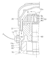
- FIG. 1 is a schematic diagram for explaining a configuration of a longitudinal section of a scroll compressor 10 according to the present embodiment.
- FIG. 2 is a partially enlarged view of FIG. 1 and 2 are not strict cross-sectional views but show cross-sectional views in different directions on the right side and the left side from the center. In addition, there are places where some of the constituent members are omitted as appropriate.
- the scroll compressor 10 includes a housing 20, a partition member 28, a scroll compression mechanism 50 including a fixed scroll 30 and a movable scroll 40, a housing 60, a drive motor 70, and a crankshaft. 80 and a lower bearing portion 90.
- the scroll compressor 10 includes a vertically long cylindrical hermetic dome-shaped housing 20.
- the housing 20 includes a substantially cylindrical body portion 21 that is open at the top and bottom, and an upper lid 22a and a lower lid 22b that are provided at the upper end and the lower end of the body portion 21, respectively.
- the body portion 21, the upper lid 22a, and the lower lid 22b are fixed by welding so as to maintain airtightness.
- the casing 20 accommodates the components of the scroll compressor 10 including the scroll compression mechanism 50, the drive motor 70, the crankshaft 80, and the lower bearing portion 90.
- the scroll compression mechanism 50 is disposed at the upper part in the body part 21.
- An oil sump space So is formed in the lower part of the housing 20.
- Refrigerating machine oil O for lubricating the scroll compression mechanism 50 and the like is stored in the oil reservoir space So.
- a suction pipe 23 is provided in the upper part of the housing 20 so as to penetrate the upper lid 22a.
- the lower end of the suction pipe 23 is connected to the suction connection port of the fixed scroll 30.
- the suction pipe 23 communicates with a compression chamber Sc of the scroll compression mechanism 50 described later.
- the low-pressure refrigerant in the refrigeration cycle before compression by the scroll compressor 10 flows into the suction pipe 23.
- the gas refrigerant is supplied to the scroll compression mechanism 50 via the suction pipe 23.
- the body portion 21 of the housing 20 is provided with a discharge pipe 24 through which a refrigerant discharged outside the housing 20 passes.
- the discharge pipe 24 flows out the high-pressure gas refrigerant compressed by the scroll compression mechanism 50 from the internal space of the housing 20 to the outside.
- R32 can be used as a refrigerant of the scroll compressor 10.
- the scroll compression mechanism 50 is disposed in the casing 20, compresses the sucked refrigerant, and forms a refrigerant flow path (refrigerant flow path) formed in the internal space of the casing 20. (Including R1 to R3).
- the scroll compression mechanism 50 includes a fixed scroll 30 disposed above the housing 60, and a movable scroll 40 that is combined with the fixed scroll 30 to form a compression chamber Sc.
- the fixed scroll 30 includes a flat fixed end plate 32 and a spiral fixed side wrap 33 protruding from the front surface of the fixed side end plate 32. And an outer edge portion 34 surrounding the fixed side wrap 33.
- the fixed side wrap 33 is formed so as to extend in a spiral shape from a discharge port 32a to be described later to the outer edge portion.
- a suction port is provided in the outer edge portion 34 of the fixed scroll 30. The refrigerant flowing from the suction pipe 23 is introduced into the compression chamber Sc of the scroll compression mechanism 50 through the suction port.
- the suction port is provided with a check valve that prevents the refrigerant from flowing backward.
- a discharge port 32a communicating with the compression chamber Sc of the scroll compression mechanism 50 is formed in the center of the fixed side end plate 32 so as to penetrate the fixed side end plate 32 in the thickness direction.
- the refrigerant compressed in the compression chamber Sc is discharged from the discharge port 32a, passes through the first refrigerant flow path R1 formed in the fixed scroll 30 and the housing 60, and flows into the high-pressure space S1.
- the movable scroll 40 includes a flat movable side end plate 42 and a spiral movable side wrap 43 protruding from the front surface of the movable side end plate 42. And a cylindrical boss portion 44 protruding from the back surface of the movable side end plate 42.
- the fixed side wrap 33 of the fixed scroll 30 and the movable side wrap 43 of the movable scroll 40 are combined so that the lower surface of the fixed side end plate 32 and the upper surface of the movable side end plate 42 face each other.
- the compression chamber Sc is formed between the adjacent fixed side wrap 33 and the movable side wrap 43.
- the boss portion 44 has a cylindrical shape with a closed upper end.
- the eccentric portion 82 of the crankshaft 80 is inserted into the hollow portion of the boss portion 44. Thereby, the movable scroll 40 and the crankshaft 80 are connected.
- the boss portion 44 is disposed in an eccentric space Sn formed between the movable scroll 40 and the housing 60.
- the eccentric part space Sn communicates with the high-pressure space S1 via an oil supply path or the like inside the crankshaft 80, and high pressure acts on the eccentric part space Sn.
- the lower surface of the movable side end plate 42 in the eccentric portion space Sn is pushed upward toward the fixed scroll 30.
- the movable scroll 40 is in close contact with the fixed scroll 30.
- the movable scroll 40 is supported by the housing 60 via an Oldham ring.
- the Oldham ring is a member that prevents the orbiting scroll 40 from rotating and revolves.
- (1-3) Housing The housing 60 is press-fitted into the body portion 21, and is fixed to the body portion 21 over the entire circumferential direction on the outer peripheral surface thereof.
- the housing 60 and the fixed scroll 30 are fixed by bolts or the like so that the upper end surface of the housing 60 is in close contact with the lower surface of the outer edge portion 34 of the fixed scroll 30.
- the housing 60 is formed with a recessed portion 61 disposed so as to be recessed in the central portion of the upper surface, and a bearing portion 62 disposed below the recessed portion 61.
- the recessed part 61 surrounds the side surface of the eccentric part space Sn in which the boss
- the bearing unit 62 is provided with a bearing 62 r that supports the main shaft 81 of the crankshaft 80.
- the bearing 62r rotatably supports the main shaft 81 inserted into the bearing 62r.
- the drive motor 70 includes an annular stator 71 fixed to the inner wall surface of the body portion 21, and a rotor that is rotatably accommodated inside the stator 71 with a gap (air gap passage) therebetween. 72.
- the rotor 72 is connected to the movable scroll 40 via a crankshaft 80 disposed so as to extend in the vertical direction along the axial center of the body portion 21. As the rotor 72 rotates, the movable scroll 40 revolves with respect to the fixed scroll 30.
- the drive motor 70 is disposed so as to form a refrigerant flow path R3 in a part between the outer periphery of the drive motor 70 and the inner wall of the housing 20. Details of the refrigerant flow path R3 will be described later.
- crankshaft 80 (drive shaft) is disposed in the body portion 21 and drives the scroll compression mechanism 50. Specifically, the crankshaft 80 transmits the driving force of the driving motor 70 to the movable scroll 40.
- the crankshaft 80 is disposed so as to extend in the vertical direction along the axis of the body portion 21, and connects the rotor 72 of the drive motor 70 and the movable scroll 40 of the scroll compression mechanism 50.
- the crankshaft 80 has a main shaft 81 whose center axis coincides with the central axis of the body portion 21, and an eccentric portion 82 that is eccentric with respect to the axial center of the body portion 21.
- the main shaft 81 is rotatably supported by a bearing 62r of the bearing portion 62 of the housing 60 and a bearing 90r of the lower bearing portion 90.
- the eccentric portion 82 is inserted into the boss portion 44 of the movable scroll 40 as described above.
- crankshaft 80 an oil supply path for supplying the refrigerating machine oil O to the scroll compression mechanism 50 and the like is formed.
- the lower end of the main shaft 81 is located in an oil sump space So formed in the lower part of the casing 20, and the refrigerating machine oil O in the oil sump space So is supplied to the scroll compression mechanism 50 and the like through an oil supply path.
- the lower bearing part 90 is provided at the lower part in the body part 21 and supports the crankshaft 80. Specifically, the lower bearing portion 90 has a bearing 90 r on the lower end side of the crankshaft 80. Thereby, the main shaft 81 of the crankshaft 80 is rotatably supported. Note that an oil pickup communicating with the oil supply path of the crankshaft 80 is fixed to the lower bearing portion 90.
- the drive motor 70 is activated. Thereby, the rotor 72 rotates with respect to the stator 71, and the crankshaft 80 fixed to the rotor 72 rotates.
- the crankshaft 80 rotates
- the movable scroll 40 connected to the crankshaft 80 revolves with respect to the fixed scroll 30.
- the low-pressure gas refrigerant in the refrigeration cycle is sucked into the compression chamber Sc from the peripheral side of the compression chamber Sc through the suction pipe 23.
- the suction pipe 23 and the compression chamber Sc no longer communicate with each other. Then, as the volume of the compression chamber Sc decreases, the pressure in the compression chamber Sc starts to increase.
- the refrigerant in the compression chamber Sc is compressed as the volume of the compression chamber Sc decreases, and finally becomes a high-pressure gas refrigerant.
- the high-pressure gas refrigerant is discharged from a discharge port 32 a located near the center of the fixed side end plate 32. Thereafter, the high-pressure gas refrigerant flows into the high-pressure space S ⁇ b> 1 via the refrigerant flow path R ⁇ b> 1 formed in the fixed scroll 30 and the housing 60, and is discharged from the discharge pipe 24.
- the scroll compressor 10 includes a first temperature sensor 15 and a second temperature sensor 25 in order to measure the temperature of the refrigerant compressed by the scroll compression mechanism 50.
- the first temperature sensor 15 includes a temperature sensing portion 15a and a screw-like portion 15n.
- the temperature sensing unit 15a includes a thermistor that measures temperature and a metal cover that protects the thermistor.
- the metal is, for example, copper.
- the metal cover of the temperature sensing unit 15a is disposed so as to be in contact with the refrigerant flowing through the second refrigerant channel R2.
- the temperature sensing unit 15a is arranged to directly measure the refrigerant temperature.
- the second refrigerant flow path R2 is a space that is continuous with the first refrigerant flow path R1 formed in the housing 60.
- the direct measurement means that the temperature of the refrigerant is directly measured, not the temperature of a pipe through which the refrigerant flows or a part that receives heat transfer from the refrigerant.
- the first temperature sensor 15 is disposed through the housing 20.
- the first temperature sensor 15 can be fixedly disposed by being screwed and sealed to a screw-type joint 21f provided on the body portion 21 of the housing 20.
- the 1st temperature sensor 15 is screwed by the screw-shaped part 15n, it can be easily attached from the outer side of the housing
- FIG. Further, the temperature sensing part 15 a of the first temperature sensor 15 is thermally insulated from the housing 20.
- the first temperature sensor 15 is disposed at a position near the outlet of the refrigerant flow path R1 of the housing 60.
- the temperature sensing part 15a is made of copper having a high thermal conductivity.
- the joint 21f is made of iron having a low heat transfer coefficient.
- the second temperature sensor 25 is arranged at a different location from the first temperature sensor 15.
- the second temperature sensor 25 is disposed on the surface of the discharge pipe 24 and measures the temperature of the surface of the discharge pipe 24.
- the second temperature sensor 25 is arranged in a range where the length of the flow path from the housing 20 is within 1 m. Therefore, the second temperature sensor 25 is disposed on the surface of the discharge pipe 24 within a range of 1 m from the main body of the compressor 10.
- the scroll compressor 10 includes a guide plate 65 as shown in FIGS.
- the first temperature sensor 15 described above measures the temperature of the space (second refrigerant flow path R2) formed by the guide plate 65.
- the guide plate 65 is disposed in the housing 20 and reduces the flow path cross-sectional area of the second refrigerant flow path R2. Specifically, the guide plate 65 is a space below the housing 60, and refrigerant is supplied to the third refrigerant flow path R ⁇ b> 3 formed in a part between the outer periphery of the drive motor 70 and the inner wall of the housing 20. Arranged to guide. In other words, the second refrigerant flow path R2 and the third refrigerant flow path R3 are continuous via the guide plate 65.
- the guide plate 65 has a shape as shown in FIG. 4, and is formed at a part between the outer periphery of the drive motor 70 and the inner wall of the housing 20 (a core cut portion of one pole portion of the stator 71).
- the second refrigerant flow path R2 is formed so as to be concentrated. For this reason, the other core cut portions can be used for oil return and the like.
- the scroll compressor 10 is connected to a control device 5 as will be described later.
- the control device 5 functions as a calculation unit 5a that calculates the refrigerant temperature estimation value HTp at the discharge port 32a based on the measurement value Tp of the first temperature sensor 15 and the measurement value Td of the second temperature sensor 25.
- the control device 5 (calculation unit 5a) estimates the temperature of the refrigerant based on the following equation (1).
- K is a correction coefficient, and is set based on the measured value of the refrigerant temperature at the discharge port 32a measured in the experimental environment.
- N is a natural number.
- the scroll compressor 10 includes the first temperature sensor 15 and the second temperature sensor 25 described above, and estimates the refrigerant temperature at the discharge port 32a. This is based on the following findings of the present inventors. In other words, as a result of diligent efforts, the present inventors have obtained knowledge that the refrigerant temperature at the discharge port 32a can be estimated with high accuracy by using the above equation (1).
- the result as shown in FIG. 5 was obtained.
- the measured value of the refrigerant temperature at the discharge port 32a, the measured value of the first temperature sensor 15, and the measured value of the second temperature sensor 25 are shown by lines T, Tp, and Td in FIG. 5, respectively.
- the estimated temperature value calculated using the above equation (1) is indicated by a line HTp.
- the horizontal axis of FIG. 5 has shown time, and the vertical axis
- shaft has shown temperature.
- the line HTp captures the line T, which is an actually measured value, well even when a sudden temperature change occurs due to a capability change or the like. Note that the safety can be improved by making the error positive when the temperature of the discharge port 32a requiring protection is increased.
- the refrigerant temperature at the discharge port 32a can be estimated with high accuracy by using the scroll compressor 10 having the first temperature sensor 15 and the second temperature sensor 25 described above.
- FIG. 7 is a diagram for explaining an example of a configuration of a refrigeration cycle apparatus 100 including the compressor 10 according to the present embodiment.
- the refrigeration cycle apparatus 100 is a water heating apparatus and / or cooling apparatus using a heat pump. Specifically, the refrigeration cycle apparatus 100 supplies heated or cooled water as a water heater or a chiller. Further, the refrigeration cycle apparatus 100 warms or cools the room using heated or cooled water as a medium.
- the refrigeration cycle apparatus 100 includes a scroll compressor 10, an accumulator 102, a four-way switching valve 103, an air heat exchanger 104, a check valve bridge 109, a first expansion mechanism 107, a second expansion mechanism ( A flow rate adjusting mechanism) 108, an economizer heat exchanger 110, and a water heat exchanger 111. Furthermore, the refrigeration cycle apparatus 100 includes a fan 105 for allowing air to pass through the air heat exchanger 104 and a motor 106 for driving the fan 105. Each device and the branch part 112 are connected by pipes 141 to 154. Each device is controlled by the control device 5.
- the “expansion mechanism” refers to an apparatus that can depressurize the refrigerant, such as an electronic expansion valve and a capillary tube. Further, the expansion mechanism can freely adjust the opening degree.
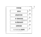
- the control device 5 executes the following control for each component device.
- the control device 5 includes a microcomputer and a memory that stores a program.
- the control device 5 has a circulation control unit 5h as shown in FIG. 8, and controls each component device of the refrigeration cycle apparatus 100 to perform control for circulating the refrigerant. . Specifically, the refrigeration cycle apparatus 100 executes control to circulate the refrigerant when heating or cooling water.
- a gas refrigerant is sent to the scroll compressor 10 under the control of the control device 5. Then, the gas refrigerant is compressed by the scroll compressor 10. The compressed gas refrigerant is sent to the water heat exchanger 111 that functions as a condenser. In the water heat exchanger 111, heat exchange is performed between the gas refrigerant and water, and the refrigerant is liquefied. Subsequently, the refrigerant is sent to the first expansion mechanism 107. The refrigerant is depressurized by the first expansion mechanism 107. Next, the refrigerant is sent to an air heat exchanger 104 that functions as an evaporator.
- the air heat exchanger 104 heat is exchanged between the refrigerant and the air, and the refrigerant is vaporized.
- the vaporized refrigerant is sent again to the scroll compressor 10. Thereafter, the refrigerant circulates through each component device of the refrigeration cycle in the same manner.
- water is sent from the water inlet side pipe 161 to the water heat exchanger 111.
- a high-temperature refrigerant flows through the water heat exchanger 111. Therefore, in the water heat exchanger 111, water is heated by the refrigerant. The heated water is discharged from the water outlet side pipe 162. In this way, heated water is supplied.
- water can be cooled by changing the flow of the refrigerant by switching the four-way switching valve 103.
- the water heat exchanger 111 functions as a refrigerant evaporator.
- the control device 5 includes an injection control unit 5i as shown in FIG. 8, and executes injection control when performing the above-described circulation control.
- a so-called injection circuit is formed by the second expansion mechanism 108, the economizer heat exchanger 110, the branch portion 112, and the pipes 152 to 154.
- the gas refrigerant compressed by the scroll compressor 10 is sent to the water heat exchanger 111 functioning as a condenser under the control of the control device 5.
- the water heat exchanger 111 heat exchange is performed between the gas refrigerant and water, and the refrigerant is liquefied.
- the liquefied refrigerant is branched at the branching portion 112 and sent to the second expansion mechanism 108.
- the second expansion mechanism 108 functions as a flow rate adjustment mechanism. Specifically, the opening degree and the like of the second expansion mechanism 108 are adjusted under the control of the control device 5. As a result, the flow rate of the branched refrigerant is adjusted. At this time, the pressure and temperature of the refrigerant decrease due to the expansion operation of the second expansion mechanism 108. Then, the refrigerant is sent from the second expansion mechanism 108 to the economizer heat exchanger 110.
- the economizer heat exchanger 110 functions as a gasification mechanism. Specifically, in the economizer heat exchanger 110, heat exchange between the refrigerant flowing from the pipe 153 to the pipe 154 (refrigerant flowing through the injection circuit) and the refrigerant flowing from the pipe 147 to the pipe 146 (refrigerant flowing through the main refrigeration cycle). The refrigerant flowing from the pipe 153 to the pipe 154 (refrigerant flowing through the injection circuit) is gasified. The gasified refrigerant is injected during the compression of the scroll compressor 10. Thereby, it adjusts so that the discharge temperature of the gas refrigerant
- “gasification” in the injection circuit is sufficient if only part of the liquid refrigerant is gasified (gas-rich state), and does not necessarily mean that all of the liquid refrigerant is gasified.
- the control device 5 includes a rotational speed control unit 5b as shown in FIG. 8, and controls the rotational speed of the drive motor 70. Specifically, the rotation speed control unit 5b controls the rotation speed of the drive motor 70 so that the estimated refrigerant temperature HTp calculated by the calculation unit 5a described above becomes the discharge target temperature.
- the control device 5 controls the rotation speed of the drive motor 70 of the scroll compressor 10 to increase.
- coolant in a refrigerating cycle increases, and the thermal radiation amount per unit time of the refrigerant
- the controller 5 stops the rotation of the drive motor 70 when the temperature of the water becomes higher than the set temperature.
- the control device 5 includes a first opening control unit 5c as shown in FIG. 8, and controls the opening of the first expansion mechanism 107. Do. Specifically, the first opening degree control unit 5c controls the opening degree of the first expansion mechanism 107 based on the refrigerant temperature estimated value HTp calculated by the calculation unit 5a.
- the control device 5 performs control so that the opening degree of the first expansion mechanism 107 increases. Thereby, the flow rate of the refrigerant passing through the air heat exchanger 104 increases, and the degree of superheat of the refrigerant sucked into the scroll compressor 10 decreases. Therefore, the refrigerant discharge temperature approaches the target discharge temperature.
- control device 5 controls the first expansion mechanism 107 so that the refrigerant subcooling degree at the outlet of the water heat exchanger 111 or the refrigerant subcooling degree at the outlet of the economizer heat exchanger 110 becomes the target subcooling degree.
- the degree of opening may be controlled.
- the control device 5 has a second opening control unit 5d as shown in FIG. 8, and controls the opening of the second expansion mechanism 108. Do.
- the opening degree of the second expansion mechanism 108 is controlled by a procedure as shown in FIG.
- the calculating part 5a of the control apparatus 5 acquires the measured value Tp of the 1st temperature sensor 15 (S1). Moreover, the calculating part 5a acquires the measured value Td of the 2nd temperature sensor 25 (S2). Here, the timing of step S1 and step S2 may be reversed, or may be simultaneous.
- the calculating part 5a calculates the temperature estimate value HTp of the refrigerant
- the second opening degree control unit 5d of the control device 5 controls the opening degree of the second expansion mechanism 108 based on the refrigerant temperature estimated value HTp calculated by the calculation unit 5a (S4).
- the control device 5 performs control so that the opening degree of the second expansion mechanism 108 is increased. Thereby, the flow rate of the refrigerant flowing into the injection circuit increases, and the temperature of the refrigerant sucked into the scroll compressor 10 decreases. Therefore, the refrigerant discharge temperature approaches the target discharge temperature.
- the scroll compressor 10 of the present embodiment includes the housing 20, the scroll compression mechanism 50, the discharge pipe 24, the first temperature sensor 15, and the second temperature sensor 25.
- the 1st temperature sensor 15 has the temperature sensing part 15a.
- the temperature sensing unit 15a is disposed in the second refrigerant flow path R2.
- the temperature sensing unit 15a can directly measure the temperature of the refrigerant (measured value Tp). Direct measurement means that the temperature of the refrigerant is directly measured, not the temperature of the pipe through which the refrigerant flows or the temperature of a component that receives heat from the refrigerant. Therefore, by using the first temperature sensor 15, it is possible to measure the temperature that quickly follows the change in the discharge temperature immediately after the discharge port 32a of the scroll compression mechanism 50.
- the second temperature sensor 25 measures the temperature of the surface of the discharge pipe 24 (measured value Td). Therefore, by using the second temperature sensor 25, it is possible to measure the temperature reflecting the influence of the heat capacity of the constituent members of the scroll compressor 10.
- the temperature of the refrigerant immediately after the discharge port 32a of the scroll compression mechanism 50 (using the two temperature values measured by the first temperature sensor 15 and the second temperature sensor 25) (The temperature estimated value HTp) can be estimated with high accuracy. As a result, the scroll compressor 10 with high reliability can be provided.
- the scroll compressor 10 is controlled so that the refrigerant discharge temperature does not exceed a predetermined value because internal components may be damaged if the refrigerant discharge temperature becomes too high.
- casing 20 of the scroll compressor 10 is measured, and the value corrected in consideration of the heat loss etc. is estimated as the discharge temperature.
- a second method there is a method in which a temperature sensor is arranged at the position of the discharge port 32a of the scroll compressor 10 where the temperature becomes the highest, and the measured value is estimated as the discharge temperature.
- the responsiveness of temperature change is delayed or dull due to the heat capacity of the casing 20 of the scroll compressor 10, or the temperature is lowered due to heat radiation to the surroundings.
- the amount of change in temperature varies greatly depending on the operating conditions. Therefore, the temperature at the discharge port 32a of the scroll compressor 10 may not be accurately estimated. As a result, the discharge temperature may exceed an allowable upper limit, and the scroll compressor 10 may be damaged. Or an excessive error is anticipated in order to ensure reliability, a compressor will be overdesigned and cost may increase.
- the upper limit of the discharge temperature to a lower value, the allowable operation area of the compressor may be reduced, and the operation of the scroll compressor 10 may become inefficient.
- liquid injection or the like may be performed to cool the discharge port 32a so that the temperature does not exceed the upper limit.
- the cooling timing may be delayed, resulting in excessive temperature rise, or conversely, excessive cooling may result in discharge wetness. As a result, the reliability of the scroll compressor 10 may be impaired.
- the second method it is conceivable to solve the problems of the first method.
- the second method it is necessary to arrange a temperature sensor in the casing 20 of the scroll compressor 10. Therefore, the installation of the temperature sensor becomes complicated and the cost increases.
- refrigerant leakage and pressure loss may occur inside the compressor.
- the temperature sensor is exposed to a high-temperature and high-pressure atmosphere, it tends to break down. Furthermore, once a failure occurs, there arises a problem that the temperature sensor cannot be easily replaced.
- the first temperature sensor 15 that is disposed in the refrigerant flow path in the housing 20 and directly measures the temperature of the refrigerant
- the second that measures the surface temperature of the discharge pipe 24. Since the temperature sensor 25 and the two temperature sensors are provided, the refrigerant discharge temperature can be calculated with high accuracy. As a result, the problems caused by the first method and the second method described above can be avoided, and a highly reliable scroll compressor 10 can be provided.
- the first temperature sensor 15 is disposed so as to penetrate the housing, and is detachably attached from the outside of the housing 20. Therefore, even if the first temperature sensor 15 fails, maintenance can be easily performed. In addition, since the first temperature sensor 15 can be easily replaced, it is not necessary to consider durability more than necessary. As a result, the manufacturing cost can be suppressed.
- the temperature sensing unit 15 a of the first temperature sensor 15 is thermally insulated from the housing 20. Therefore, the temperature of the refrigerant can be measured with high accuracy.
- the scroll compressor 10 further includes a guide plate 65 that is disposed in the housing 20 and reduces the flow passage cross-sectional area of the refrigerant flow passage.
- the guide plate 65 is arranged so that the cross-sectional area of the flow path becomes small, the flow rate of the refrigerant in the space is increased.
- the first temperature sensor 15 measures the temperature of the space (second refrigerant flow path R2) formed by the guide plate 65. Therefore, with such a configuration, the temperature of the refrigerant having a high flow rate is measured, so that the responsiveness can be improved.
- the scroll compressor 10 is arranged such that the drive motor 70 forms the third refrigerant flow path R3 in a part between the outer periphery of the drive motor 70 and the inner wall of the housing 20.
- the And the guide plate 65 is arrange
- coolant may be guide
- the guide plate 65 is arranged so that the refrigerant is concentrated on a part (one core part of the core cut part) between the outer periphery of the drive motor 70 and the inner wall of the housing 20. Therefore, another core cut part can be utilized for oil return etc.
- the discharge pipe 24 is disposed on the substantially opposite side of the region near the inner wall of the housing 20 from the region formed by the guide plate 65 in plan view.
- the second temperature sensor 25 can measure the temperature reflecting the influence that is not reflected in the first temperature sensor 15.
- the first temperature sensor 15 can measure a temperature at which the influence of the heat capacity of the components of the scroll compressor 10 is not reflected so much.
- the second temperature sensor 25 can measure a temperature that largely reflects the influence of the heat capacity of the components of the scroll compressor 10. Therefore, the temperature measurement value of the second temperature sensor 25 reflects the influence that is not reflected in the first temperature sensor 15.
- the second temperature sensor 25 is disposed in a range where the length of the flow path from the housing 20 is within 1 m. With such a configuration, the influence of heat loss and heat capacity can be suppressed.
- the refrigeration cycle apparatus 100 can use the water heat exchanger 111 and the air heat exchanger 104 as a condenser and an evaporator, respectively.
- the refrigeration cycle apparatus 100 has a refrigeration cycle in which refrigerant flows in the order of the scroll compressor 10, the condenser (water heat exchanger 111), the first expansion mechanism 107, and the evaporator (air heat exchanger 104).
- the refrigeration cycle apparatus 100 further includes a calculation unit 5a that calculates the temperature of the refrigerant discharged from the scroll compression mechanism 50 using the first temperature sensor 15 and the second temperature sensor 25.
- the refrigeration cycle apparatus 100 can estimate the refrigerant temperature immediately after the discharge port 32a of the scroll compression mechanism 50 with high accuracy.
- the refrigeration cycle apparatus 100 further includes a rotation speed control unit 5b that controls the rotation speed of the drive motor 70 based on the refrigerant temperature calculated by the calculation unit 5a. With such a configuration, a highly reliable refrigeration cycle apparatus 100 can be provided.
- the pressure in the high pressure state can be reduced by reducing the rotation speed of the drive motor 70 under the control of the rotation speed control unit 5b.
- the discharge temperature can be suppressed, and it is possible to avoid situations such as the deterioration of oil and the damage of machine parts.
- the refrigeration cycle apparatus 100 further includes pipes 152 to 154 (injection pipes), a second expansion mechanism 108 (flow rate adjustment mechanism), and a second opening degree control unit 5d.
- the pipes 152 to 154 branch a part of the pipe from the water heat exchanger 111 (condenser) toward the first expansion mechanism 107 and are connected to the scroll compressor 10.
- the second expansion mechanism 108 adjusts the flow rate of the refrigerant in the pipes 152 to 154.
- the second opening degree control unit 5d controls the opening degree of the second expansion mechanism 108 based on the refrigerant temperature calculated by the calculation unit 5a. With such a configuration, a highly reliable refrigeration cycle apparatus 100 can be provided.
- the refrigeration cycle apparatus 100 further includes an economizer heat exchanger 110 (gasification mechanism) that gasifies the liquid refrigerant flowing through the pipes 152 to 154.
- an economizer heat exchanger 110 gasification mechanism
- the refrigeration cycle apparatus 100 according to the present embodiment is suitable for applications that require the refrigerant discharged from the scroll compressor 10 to have a high temperature.
- R32 since the discharge temperature becomes high, it is preferable to use the refrigeration cycle apparatus 100 according to the present embodiment.
- the refrigeration cycle apparatus 100 according to the present embodiment is suitable for application to a hot water heater or the like using a heat pump as an alternative to combustion heating.
- the second temperature sensor 25 measures the temperature of the surface of the discharge pipe 24, but is not limited to this. Specifically, the second temperature sensor 25 is disposed at a different location from the first temperature sensor 15, and the temperature of any one of the surface of the discharge pipe 24, the internal space of the discharge pipe 24, or the surface of the housing 20 is measured. You may measure. Even if the second temperature sensor 25 is disposed in these places, the temperature of the refrigerant at the discharge port 32a can be estimated with high accuracy by combining with the measurement value of the first temperature sensor 15.
- the refrigeration cycle apparatus 100 heats or cools water, but is not limited to this.
- the refrigeration cycle apparatus 100 may be one that heats and cools brine as a fluid other than water, or heats the room as a direct expansion air conditioner by an indoor unit in which the water heat exchanger is replaced with an air heat exchanger. It may also be cooled.
- the compressor according to the present embodiment may be another compressor such as a rotary compressor.
- the present disclosure is not limited to the above embodiments as they are.
- the present disclosure can be embodied by modifying the components without departing from the scope of the disclosure in the implementation stage. Further, the present disclosure can form various disclosures by appropriately combining a plurality of constituent elements disclosed in the respective embodiments. For example, some components may be deleted from all the components shown in the embodiment. Furthermore, constituent elements may be appropriately combined in different embodiments.
- Refrigeration cycle apparatus 104 Air heat exchange (Condenser) 107 First expansion mechanism (expansion mechanism) 108 Second expansion mechanism (flow rate adjustment mechanism) 110 Economizer heat exchanger (gasification mechanism)
- Water heat exchanger (condenser) 152 Piping (Injection piping) 153 Piping (Injection piping) 154 Piping (Injection piping)
Abstract
信頼性の高いスクロール圧縮機(10)を提供する。スクロール圧縮機(10)は、筐体(20)と、スクロール圧縮機構(50)と、吐出管(24)と、第1温度センサ(15)と、第2温度センサ(25)とを備える。スクロール圧縮機構(50)は、筐体(20)内に配置され、吸入した冷媒を圧縮し、圧縮した冷媒を筐体(20)の内部空間に形成される冷媒流路(R1~R3)に吐出する。吐出管(24)は、筐体(20)の内部空間から外部に圧縮した冷媒を流すものである。第1温度センサ(15)は、感温部(15a)を有し、感温部(15a)は冷媒流路(R2)に配置されて冷媒の温度を直接的に計測する。第2温度センサ(25)は、第1温度センサ(15)とは異なる場所に配置され、吐出管(24)の表面、吐出管(24)の内部空間、又は筐体(20)の表面のいずれかの温度を計測するものである。
Description
圧縮機及び冷凍サイクル装置に関する。
圧縮機本体の過圧縮・異常高温を防止するために、圧縮機の吐出ガスの温度測定が行なわれる。特許文献1(特開平2-241998号)には、吐出温度スイッチの温度計プローブを圧縮機本体の脈動が十分に減衰した下流に設置する吐出温度スイッチが開示されている。
しかしながら、上述した特許文献1に記載の技術では、圧縮された直後の吐出ガスの温度測定しているものではないので、温度測定の応答遅れが生じることがある。これに起因して、圧縮機の信頼性が損なわれることがある。
第1観点の圧縮機は、筐体と、圧縮機構と、吐出管と、第1温度センサと、第2温度センサと、を備える。圧縮機構は、筐体内に配置され、吸入した冷媒を圧縮し、圧縮した冷媒を筐体の内部空間に形成される冷媒流路に吐出する。吐出管は、筐体の内部空間から外部に圧縮した冷媒を流すものである。第1温度センサは、感温部を有する。感温部は、冷媒流路に配置される。感温部は、冷媒の温度を直接的に計測する。直接的に計測するとは、冷媒が内部を流れるパイプや、冷媒から熱伝達を受ける部品の温度を計測するのではなく、冷媒の温度を直接計測するとの意味である。第2温度センサは、第1温度センサとは異なる場所に配置され、吐出管の表面、吐出管の内部空間、又は筐体の表面のいずれかの温度を計測するものである。このような構成により、圧縮機の構成部材の熱容量と放熱の影響が反映された温度を計測でき、信頼性の高い圧縮機を提供できる。
第2観点の圧縮機は、第1観点の圧縮機であって、第2温度センサが、吐出管の表面の温度を計測する。このような構成により、より精度よく圧縮機の温度を計測できる。
第3観点の圧縮機は、第1観点又は第2観点の圧縮機であって、第1温度センサが、筐体を貫通して配置されている。また、第1温度センサが、筐体の外側から着脱自在に取り付けられるものである。このような構成により、メンテナンスを容易に行なうことができる。
第4観点の圧縮機は、第1観点から第3観点のいずれかの圧縮機であって、第1温度センサの感温部が、筐体から熱絶縁されているものである。このような構成により、冷媒の温度を高精度に測定できる。
第5観点の圧縮機は、第1観点から第4観点のいずれかの圧縮機であって、筐体内に配置され、冷媒流路の流路断面積を小さくする案内板をさらに備える。そして、第1温度センサが、案内板により形成される空間の温度を計測する。このような構成により、流速の早い冷媒の温度を測定することになり、応答性を向上することができる。
第6観点の圧縮機は、第5観点の圧縮機であって、筐体内で圧縮機構の下方に配置され、圧縮機構を駆動するモータをさらに備える。モータは、モータの外周と筐体の内壁との間の一部に、冷媒流路を形成するように配置される。そして、案内板が、モータの外周と筐体の内壁との間の冷媒流路に冷媒を誘導するように配置される。このような構成により装置のコンパクト化、低コスト化を実現できる。
第7観点の圧縮機は、第5観点又は第6観点の圧縮機であって、吐出管が、筐体の内壁の近傍領域のうち、案内板により形成される領域とは平面視で略反対側に配置される。このような構成により、第2温度センサが、第1温度センサの影響を受けない情報が反映された温度を計測できる。
第8観点の圧縮機は、第1観点から第7観点のいずれかの圧縮機であって、第2温度センサが、筐体からの流路の長さが1m以内の範囲に配置されるものである。このような構成により、伝熱ロスや熱容量の影響を抑制することができる。
第9観点の冷凍サイクル装置は、第1観点から第8観点のいずれかの圧縮機、凝縮器、膨張機構、蒸発器の順に冷媒が流れる冷凍サイクルを有する。また、第1温度センサ及び第2温度センサを用いて、圧縮機構から吐出された冷媒の温度を演算する演算部をさらに備える。このような構成により、圧縮機構の吐出ポート直後の冷媒温度を高精度に推定し得る冷凍サイクル装置を提供できる。
第10観点の冷凍サイクル装置は、第9観点の冷凍サイクル装置であって、圧縮機が、筐体内で圧縮機構の下方に配置され、圧縮機構を駆動するモータを有するものである。また、演算部により演算された冷媒の温度に基づいてモータの回転数を制御する回転数制御部をさらに備える。このような構成により、信頼性の高い圧縮機を提供できる。
第11観点の冷凍サイクル装置は、第9観点又は第10観点の冷凍サイクル装置であって、インジェクション配管と、流量調整機構と、開度制御部と、をさらに備える。インジェクション配管は、凝縮器から膨張機構に向かう配管の一部を分岐して、圧縮機に接続する。流量調整機構は、インジェクション配管の冷媒の流量を調整する。開度制御部は、演算部により演算された冷媒の温度に基づいて、流量調整機構の開度を制御する。このような構成により、信頼性の高い冷凍サイクル装置を提供できる。
第12観点の冷凍サイクル装置は、第11観点の冷凍サイクル装置であって、インジェクション配管に流れる液冷媒をガス化するガス化機構をさらに備える。このような構成により、吐出温度が目標値となるようにさらに高精度に制御できる。なお、ここでいう「ガス化」とは、液冷媒の一部でもガス化していればよく、必ずしも液冷媒の全てをガス化することを意味するものではない。
(1)スクロール圧縮機の構成
図1は本実施形態に係るスクロール圧縮機10の縦断面の構成を説明するための模式図である。図2は図1の一部拡大図である。なお、図1,2は、厳密な断面図ではなく、中心から右側と左側とで異なる方向の断面図を示している。また、構成部材の一部を適宜省略している箇所がある。
図1は本実施形態に係るスクロール圧縮機10の縦断面の構成を説明するための模式図である。図2は図1の一部拡大図である。なお、図1,2は、厳密な断面図ではなく、中心から右側と左側とで異なる方向の断面図を示している。また、構成部材の一部を適宜省略している箇所がある。
スクロール圧縮機10は、図1に示されるように、筐体20と、仕切部材28と、固定スクロール30及び可動スクロール40を含むスクロール圧縮機構50と、ハウジング60と、駆動モータ70と、クランクシャフト80と、下部軸受部90とを備える。
以下、構成部材の位置関係等を説明するため、「上」「下」等の表現を用いる場合がある。ここでは、図1の矢印Uの方向を上、矢印Uと逆方向を下と呼ぶ。また、以下の説明では、「垂直」「水平」「縦」「横」等の表現を用いる場合があるが、上下方向を垂直方向かつ縦方向とする。
(1-1)筐体
スクロール圧縮機10は、縦長円筒状の密閉ドーム型の筐体20を有する。筐体20は、上下が開口した略円筒状の胴体部21と、胴体部21の上端および下端にそれぞれ設けられた上蓋22aおよび下蓋22bとを有する。胴体部21と、上蓋22aおよび下蓋22bとは、気密を保つように溶接により固定される。
スクロール圧縮機10は、縦長円筒状の密閉ドーム型の筐体20を有する。筐体20は、上下が開口した略円筒状の胴体部21と、胴体部21の上端および下端にそれぞれ設けられた上蓋22aおよび下蓋22bとを有する。胴体部21と、上蓋22aおよび下蓋22bとは、気密を保つように溶接により固定される。
筐体20には、スクロール圧縮機構50、駆動モータ70、クランクシャフト80、および下部軸受部90を含むスクロール圧縮機10の構成機器が収容される。スクロール圧縮機構50は、胴体部21内の上部に配置される。また、筐体20の下部には油溜まり空間Soが形成される。油溜まり空間Soには、スクロール圧縮機構50等を潤滑するための冷凍機油Oが溜められる。
筐体20の上部には、吸入管23が上蓋22aを貫通して設けられる。吸入管23の下端は、固定スクロール30の吸入接続口に接続される。これにより、吸入管23は、後述するスクロール圧縮機構50の圧縮室Scと連通する。吸入管23には、スクロール圧縮機10による圧縮前の、冷凍サイクルにおける低圧の冷媒が流入する。そして、吸入管23を経由してガス冷媒がスクロール圧縮機構50に供給される。
筐体20の胴体部21には、筐体20外に吐出される冷媒が通過する吐出管24が設けられる。吐出管24は、筐体20の内部空間から外部に、スクロール圧縮機構50により圧縮した高圧のガス冷媒を流出する。
なお、スクロール圧縮機10の冷媒としては、例えばR32を用いることができる。
(1-2)スクロール圧縮機構
スクロール圧縮機構50は、筐体20内に配置され、吸入した冷媒を圧縮し、圧縮した冷媒を筐体20の内部空間に形成される冷媒流路(冷媒流路R1~R3を含む)に吐出する。
スクロール圧縮機構50は、筐体20内に配置され、吸入した冷媒を圧縮し、圧縮した冷媒を筐体20の内部空間に形成される冷媒流路(冷媒流路R1~R3を含む)に吐出する。
具体的に、スクロール圧縮機構50は、図1,2に示されるように、ハウジング60の上方に配置される固定スクロール30と、固定スクロール30と組み合わされて圧縮室Scを形成する可動スクロール40とを有する。
(1-2-1)固定スクロール
固定スクロール30は、図1,2に示されるように、平板状の固定側鏡板32と、固定側鏡板32の前面から突出する渦巻状の固定側ラップ33と、固定側ラップ33を囲む外縁部34とを有する。固定側ラップ33は、後述する吐出口32aから外縁部34に亘って渦巻き状に延びて形成されるものである。また、固定スクロール30の外縁部34には吸入口が設けられる。この吸入口を介して、吸入管23から流入する冷媒がスクロール圧縮機構50の圧縮室Scに導入される。なお、吸入口には、冷媒の逆流を防ぐ逆止弁が設けられる。
固定スクロール30は、図1,2に示されるように、平板状の固定側鏡板32と、固定側鏡板32の前面から突出する渦巻状の固定側ラップ33と、固定側ラップ33を囲む外縁部34とを有する。固定側ラップ33は、後述する吐出口32aから外縁部34に亘って渦巻き状に延びて形成されるものである。また、固定スクロール30の外縁部34には吸入口が設けられる。この吸入口を介して、吸入管23から流入する冷媒がスクロール圧縮機構50の圧縮室Scに導入される。なお、吸入口には、冷媒の逆流を防ぐ逆止弁が設けられる。
固定側鏡板32の中央部には、スクロール圧縮機構50の圧縮室Scに連通する吐出口32aが、固定側鏡板32を厚さ方向に貫通して形成される。圧縮室Scで圧縮された冷媒は、吐出口32aから吐出され、固定スクロール30およびハウジング60に形成された第1冷媒流路R1を通過して、高圧空間S1へ流入する。
(1-2-2)可動スクロール
可動スクロール40は、図1,2に示されるように、平板状の可動側鏡板42と、可動側鏡板42の前面から突出する渦巻状の可動側ラップ43と、可動側鏡板42の背面から突出する円筒状のボス部44とを有する。
可動スクロール40は、図1,2に示されるように、平板状の可動側鏡板42と、可動側鏡板42の前面から突出する渦巻状の可動側ラップ43と、可動側鏡板42の背面から突出する円筒状のボス部44とを有する。
ここで、固定スクロール30の固定側ラップ33と、可動スクロール40の可動側ラップ43とは、固定側鏡板32の下面と可動側鏡板42の上面とが対向するように組み合わされる。これにより、隣接する固定側ラップ33と可動側ラップ43との間に、圧縮室Scが形成される。そして、可動スクロール40が固定スクロール30に対して公転することにより、圧縮室Scの体積が周期的に変化する。これにより、吸入管23から吸入された冷媒が圧縮室Scで圧縮される。
ボス部44は、上端の塞がれた円筒状の形態を有する。ボス部44の中空部には、クランクシャフト80の偏心部82が挿入される。これにより、可動スクロール40とクランクシャフト80とが連結される。ボス部44は、可動スクロール40とハウジング60との間に形成される偏心部空間Snに配置される。偏心部空間Snは、クランクシャフト80内部の給油経路等を介して高圧空間S1と連通しており、偏心部空間Snには高い圧力が作用する。この圧力により、偏心部空間Sn内の可動側鏡板42の下面は、固定スクロール30に向かって上方に押される。これにより、可動スクロール40は、固定スクロール30に密着する。
なお、可動スクロール40は、オルダムリングを介してハウジング60に支持される。オルダムリングは、可動スクロール40の自転を防止し、公転させる部材である。
(1-3)ハウジング
ハウジング60は、胴体部21に圧入され、その外周面において周方向の全体に亘って胴体部21に固定される。また、ハウジング60と固定スクロール30とは、ハウジング60の上端面が、固定スクロール30の外縁部34の下面と密着するように、ボルト等により固定される。
ハウジング60は、胴体部21に圧入され、その外周面において周方向の全体に亘って胴体部21に固定される。また、ハウジング60と固定スクロール30とは、ハウジング60の上端面が、固定スクロール30の外縁部34の下面と密着するように、ボルト等により固定される。
ハウジング60には、上面中央部に凹むように配置される凹部61と、凹部61の下方に配置される軸受部62とが形成される。
凹部61は、可動スクロール40のボス部44が配置される偏心部空間Snの側面を囲む。
軸受部62には、クランクシャフト80の主軸81を軸支する軸受62rが配置される。軸受62rは、軸受62rに挿入された主軸81を回転自在に支持する。
(1-4)駆動モータ
駆動モータ70は、胴体部21の内壁面に固定された環状のステータ71と、ステータ71の内側に、隙間(エアギャップ通路)を空けて回転自在に収容されたロータ72とを有する。
駆動モータ70は、胴体部21の内壁面に固定された環状のステータ71と、ステータ71の内側に、隙間(エアギャップ通路)を空けて回転自在に収容されたロータ72とを有する。
ロータ72は、胴体部21の軸心に沿って上下方向に延びるように配置されたクランクシャフト80を介して可動スクロール40と連結される。ロータ72が回転することで、可動スクロール40は、固定スクロール30に対して公転する。
また、駆動モータ70は、駆動モータ70の外周と筐体20の内壁との間の一部に、冷媒流路R3を形成するように配置される。冷媒流路R3の詳細については後述する。
(1-5)クランクシャフト
クランクシャフト80(駆動軸)は、胴体部21内に配置され、スクロール圧縮機構50を駆動するものである。具体的には、クランクシャフト80は、駆動モータ70の駆動力を可動スクロール40に伝達する。クランクシャフト80は、胴体部21の軸心に沿って上下方向に延びるように配置され、駆動モータ70のロータ72と、スクロール圧縮機構50の可動スクロール40とを連結する。
クランクシャフト80(駆動軸)は、胴体部21内に配置され、スクロール圧縮機構50を駆動するものである。具体的には、クランクシャフト80は、駆動モータ70の駆動力を可動スクロール40に伝達する。クランクシャフト80は、胴体部21の軸心に沿って上下方向に延びるように配置され、駆動モータ70のロータ72と、スクロール圧縮機構50の可動スクロール40とを連結する。
クランクシャフト80は、胴体部21の軸心と中心軸が一致する主軸81と、胴体部21の軸心に対して偏心した偏心部82とを有する。主軸81は、ハウジング60の軸受部62の軸受62r、および、下部軸受部90の軸受90rにより、回転自在に支持される。偏心部82は、前述のように可動スクロール40のボス部44に挿入される。
クランクシャフト80の内部には、スクロール圧縮機構50等に冷凍機油Oを供給するための給油経路が形成される。主軸81の下端は、筐体20の下部に形成された油溜まり空間So内に位置し、油溜まり空間Soの冷凍機油Oは、給油経路を通じてスクロール圧縮機構50等に供給される。
(1-6)下部軸受部
下部軸受部90は、胴体部21内の下部に設けられ、クランクシャフト80を軸支するものである。具体的には、下部軸受部90は、クランクシャフト80の下端側に軸受90rを有する。これにより、クランクシャフト80の主軸81が回転自在に支持される。なお、下部軸受部90には、クランクシャフト80の給油経路に連通するオイルピックアップが固定される。
下部軸受部90は、胴体部21内の下部に設けられ、クランクシャフト80を軸支するものである。具体的には、下部軸受部90は、クランクシャフト80の下端側に軸受90rを有する。これにより、クランクシャフト80の主軸81が回転自在に支持される。なお、下部軸受部90には、クランクシャフト80の給油経路に連通するオイルピックアップが固定される。
(2)スクロール圧縮機の動作
次に、上述したスクロール圧縮機10の動作について説明する。
次に、上述したスクロール圧縮機10の動作について説明する。
まず、駆動モータ70が起動する。これにより、ロータ72がステータ71に対して回転し、ロータ72と固定されたクランクシャフト80が回転する。クランクシャフト80が回転すると、クランクシャフト80と連結された可動スクロール40が固定スクロール30に対して公転する。そして、冷凍サイクルにおける低圧のガス冷媒が、吸入管23を通って、圧縮室Scの周縁側から、圧縮室Scに吸引される。可動スクロール40が公転するのに従い、吸入管23と圧縮室Scとが連通しなくなる。そして、圧縮室Scの容積が減少するのに伴って、圧縮室Scの圧力が上昇し始める。
圧縮室Sc内の冷媒は、圧縮室Scの容積が減少するのに伴って圧縮され、最終的に高圧のガス冷媒となる。高圧のガス冷媒は、固定側鏡板32の中心付近に位置する吐出口32aから吐出される。その後、高圧のガス冷媒は、固定スクロール30およびハウジング60に形成された冷媒流路R1を経由して高圧空間S1へ流入し、吐出管24から吐出される。
(3)冷媒温度の計測
次に、上述したスクロール圧縮機10における冷媒の温度を計測するための構成について説明する。
次に、上述したスクロール圧縮機10における冷媒の温度を計測するための構成について説明する。
(3-1)温度センサの構成
スクロール圧縮機10は、スクロール圧縮機構50で圧縮された冷媒の温度を計測するために、第1温度センサ15と第2温度センサ25とを備えている。
スクロール圧縮機10は、スクロール圧縮機構50で圧縮された冷媒の温度を計測するために、第1温度センサ15と第2温度センサ25とを備えている。
第1温度センサ15は、図3に示すように、感温部15aと、ネジ状部分15nとを有する。感温部15aは、温度を計測するサーミスタと、サーミスタを保護する金属カバーとを有する。金属とは、たとえば、銅である。図2に示すように、感温部15aの金属カバーは、第2冷媒流路R2を流れる冷媒に接するように配置される。言い換えると、感温部15aは、冷媒温度を直接的に計測するように配置される。ここで、第2冷媒流路R2は、ハウジング60に形成される第1冷媒流路R1と連続する空間である。また、直接的に計測するとは、冷媒が内部を流れるパイプや、冷媒から熱伝達を受ける部品の温度を計測するのではなく、冷媒の温度を直接計測するとの意味である。
第1温度センサ15は、筐体20を貫通して配置されている。この第1温度センサ15は、筐体20の胴体部21に設けられた、ねじ込み式の継手21fに螺着し、シールすることで固定して配置できるものである。また、第1温度センサ15は、ネジ状部分15nで螺着されるので、筐体20の外側から容易に取り付けることができる。また、第1温度センサ15の感温部15aは、筐体20からは熱絶縁されている。第1温度センサ15は、ハウジング60の冷媒流路R1の流出口に近い位置に配置される。なお、感温部15aは熱伝導率の高い銅などにより構成される。また、継手21fは熱伝達率の低い鉄などにより構成される。
第2温度センサ25は、第1温度センサ15とは異なる場所に配置される。ここでは、第2温度センサ25は、図1に示すように、吐出管24の表面に配置され、吐出管24の表面の温度を計測する。また、第2温度センサ25は、筐体20からの流路の長さが1m以内の範囲に配置される。したがって、第2温度センサ25は、圧縮機10本体から1m以内の範囲の吐出管24の表面に配置される。
(3-2)案内板の配置
スクロール圧縮機10は、図1,2に示すように、案内板65を備える。上述の第1温度センサ15は、案内板65により形成される空間(第2冷媒流路R2)の温度を計測する。
スクロール圧縮機10は、図1,2に示すように、案内板65を備える。上述の第1温度センサ15は、案内板65により形成される空間(第2冷媒流路R2)の温度を計測する。
案内板65は、筐体20内に配置され、第2冷媒流路R2の流路断面積を小さくするものである。具体的には、案内板65は、ハウジング60の下方の空間であって、駆動モータ70の外周と筐体20の内壁との間の一部に形成される第3冷媒流路R3に冷媒を誘導するように配置される。言い換えると、案内板65を介して第2冷媒流路R2と第3冷媒流路R3とが連続している。
なお、案内板65は、図4に示すような形状を有しており、駆動モータ70の外周と筐体20の内壁との間の一部(ステータ71の一極部分のコアカット部)に集中するように第2冷媒流路R2を形成する。そのため、その他のコアカット部を油戻し等のために利用することが可能となる。
(3-3)冷媒温度の演算
スクロール圧縮機10は、後述するような制御装置5に接続する。制御装置5は、第1温度センサ15の計測値Tp及び第2温度センサ25の計測値Tdに基づいて、吐出口32aにおける冷媒の温度推定値HTpを演算する演算部5aとして機能する。具体的に、制御装置5(演算部5a)は、下式(1)に基づいて冷媒の温度を推定する。なお、Kは補正係数であり、実験環境において計測された吐出口32aにおける冷媒温度の実測値に基づいて設定される。また、nは自然数である。
スクロール圧縮機10は、後述するような制御装置5に接続する。制御装置5は、第1温度センサ15の計測値Tp及び第2温度センサ25の計測値Tdに基づいて、吐出口32aにおける冷媒の温度推定値HTpを演算する演算部5aとして機能する。具体的に、制御装置5(演算部5a)は、下式(1)に基づいて冷媒の温度を推定する。なお、Kは補正係数であり、実験環境において計測された吐出口32aにおける冷媒温度の実測値に基づいて設定される。また、nは自然数である。
(3-4)温度推定の検証例
本実施形態に係るスクロール圧縮機10は、上述した第1温度センサ15及び第2温度センサ25を有して、吐出口32aにおける冷媒温度を推定するものであるが、これは、本発明者らの下記の知見に基づいている。言い換えると、本発明者らは、鋭意努力の結果、上式(1)を用いることで、高精度に吐出口32aにおける冷媒温度を推定できるとの知見を得た。
本実施形態に係るスクロール圧縮機10は、上述した第1温度センサ15及び第2温度センサ25を有して、吐出口32aにおける冷媒温度を推定するものであるが、これは、本発明者らの下記の知見に基づいている。言い換えると、本発明者らは、鋭意努力の結果、上式(1)を用いることで、高精度に吐出口32aにおける冷媒温度を推定できるとの知見を得た。
一例として、スクロール圧縮機10を制御したときの温度センサの計測値を示すと、図5のような結果が得られた。ここでは、吐出口32aにおける冷媒温度の実測値、第1温度センサ15の計測値、第2温度センサ25の計測値が、それぞれ図5の線T,Tp,Tdで示されている。また、上式(1)を用いて演算された温度推定値が、線HTpで示されている。なお、図5の横軸は時間を示しており、縦軸は温度を示している。
図5の点線部分A1,A2等に着目すると、能力変動等による急激な温度変化が生じたときでも、線HTpが実測値である線Tを良くとらえていることが認識される。なお、保護が必要となる吐出口32aの温度上昇時に誤差がプラスになるようにすることで、安全性を高めることができる。
また、吐出口32aにおける冷媒温度の実測値Tを横軸にとり、上式(1)を用いて演算された温度推定値HTpを縦軸にとると、図6に示すような結果が得られた。ここでは、推定精度が概ね±10℃以下であることが認識される。
このように、上述した第1温度センサ15及び第2温度センサ25を有するスクロール圧縮機10を用いることで、高精度に吐出口32aにおける冷媒温度を推定することができることが確認された。
(4)冷凍サイクル装置
(4-1)冷凍サイクル装置の構成
図7は本実施形態に係る圧縮機10を備えた冷凍サイクル装置100の構成の一例を説明するための図である。
(4-1)冷凍サイクル装置の構成
図7は本実施形態に係る圧縮機10を備えた冷凍サイクル装置100の構成の一例を説明するための図である。
ここでは、冷凍サイクル装置100は、ヒートポンプを用いた水の加熱装置及び/又は冷却装置である。具体的に、冷凍サイクル装置100は、給湯器または冷水器として、加熱または冷却された水を供給する。また、冷凍サイクル装置100は、加熱または冷却された水を媒体として、室内を暖めたり、冷やしたりする。
冷凍サイクル装置100は、図7に示すように、スクロール圧縮機10、アキュムレータ102、四路切換弁103、空気熱交換器104、逆止弁ブリッジ109、第1膨張機構107、第2膨張機構(流量調整機構)108、エコノマイザ熱交換器110、水熱交換器111を備える。さらに、冷凍サイクル装置100は、空気熱交換器104に空気を通過させるためのファン105と、ファン105を駆動するモータ106とを備える。なお、各機器および分岐部112は、配管141~154で接続される。また、各装置は
制御装置5により制御される。
制御装置5により制御される。
なお、本実施形態において「膨張機構」とは、冷媒を減圧できるものをいい、例えば電子膨張弁、キャピラリーチューブがこれに該当する。また、膨張機構は、開度を自在に調節できるものである。
(4-2)冷凍サイクル装置の動作
冷凍サイクル装置100では、制御装置5が、各構成機器に対して以下の制御を実行する。なお、制御装置5は、マイクロコンピュータ及びプログラムを格納したメモリなどにより構成される。
冷凍サイクル装置100では、制御装置5が、各構成機器に対して以下の制御を実行する。なお、制御装置5は、マイクロコンピュータ及びプログラムを格納したメモリなどにより構成される。
(4-2-1)循環制御
制御装置5は、図8に示すように循環制御部5hを有しており、冷凍サイクル装置100の各構成機器を制御して、冷媒を循環する制御を行なう。具体的には、冷凍サイクル装置100は、水を加熱又は冷却する際に冷媒を循環する制御を実行する。
制御装置5は、図8に示すように循環制御部5hを有しており、冷凍サイクル装置100の各構成機器を制御して、冷媒を循環する制御を行なう。具体的には、冷凍サイクル装置100は、水を加熱又は冷却する際に冷媒を循環する制御を実行する。
例えば、水を加熱する際には、制御装置5の制御により、スクロール圧縮機10にガス冷媒が送られる。そして、スクロール圧縮機10により、ガス冷媒が圧縮される。圧縮されたガス冷媒は、凝縮器として機能する水熱交換器111に送られる。水熱交換器111ではガス冷媒と水とが熱交換され、冷媒が液化される。続いて、冷媒は、第1膨張機構107に送られる。第1膨張機構107により、冷媒は減圧される。次に、冷媒は、蒸発器として機能する空気熱交換器104に送られる。空気熱交換器104では冷媒と空気とが熱交換され、冷媒が気化される。そして、気化された冷媒は、スクロール圧縮機10へ再び送られる。この後は、同様にして冷凍サイクルの各構成機器を冷媒が循環する。
そして、冷媒の循環が開始したタイミング以後に、水入側配管161から水熱交換器111に水が送られる。この際、水熱交換器111に高温の冷媒が流れている。そのため、水熱交換器111では、冷媒により水が加熱される。加熱された水は、水出口側配管162より排出される。このようにして加熱された水が供給される。
なお、四路切換弁103の切換により冷媒の流れを変更することで、水を冷却することができる。この場合は、水熱交換器111が、冷媒の蒸発器として機能することになる。
(4-2-2)インジェクション制御
制御装置5は、図8に示すようにインジェクション制御部5iを有しており、上述した循環制御を行なう際にインジェクション制御を実行する。本実施形態に係る冷凍サイクル装置100では、第2膨張機構108、エコノマイザ熱交換器110、分岐部112、配管152~154により、いわゆるインジェクション回路が形成されている。
制御装置5は、図8に示すようにインジェクション制御部5iを有しており、上述した循環制御を行なう際にインジェクション制御を実行する。本実施形態に係る冷凍サイクル装置100では、第2膨張機構108、エコノマイザ熱交換器110、分岐部112、配管152~154により、いわゆるインジェクション回路が形成されている。
例えば、水を加熱する場合には、制御装置5の制御により、スクロール圧縮機10で圧縮されたガス冷媒が、凝縮器として機能する水熱交換器111に送られる。水熱交換器111ではガス冷媒と水とが熱交換され、冷媒が液化される。液化された冷媒は、分岐部112で分岐されて、第2膨張機構108に送られる。
ここで、第2膨張機構108は流量調整機構として機能する。具体的には、制御装置5の制御により、第2膨張機構108の開度等が調整される。これにより、分岐される冷媒の流量が調整される。この際、第2膨張機構108の絞り膨張作用により冷媒の圧力及び温度は低下する。そして、第2膨張機構108からエコノマイザ熱交換器110に冷媒が送られる。
エコノマイザ熱交換器110はガス化機構として機能する。具体的には、エコノマイザ熱交換器110において、配管153から配管154に流れる冷媒(インジェクション回路を流れる冷媒)と配管147から配管146に流れる冷媒(主となる冷凍サイクルを流れる冷媒)との熱交換が行なわれて、配管153から配管154に流れる冷媒(インジェクション回路を流れる冷媒)がガス化される。そして、ガス化された冷媒は、スクロール圧縮機10の圧縮途中にインジェクションされる。これにより、スクロール圧縮機10で圧縮されるガス冷媒の吐出温度が高くなりすぎないように調整される。なお、ここでのインジェクション回路における「ガス化」とは、液冷媒の一部でもガス化していればよく(ガスリッチな状態)、必ずしも液冷媒の全てをガス化することを意味するものではない。
(4-2-3)駆動モータの回転数制御
制御装置5は、図8に示すように回転数制御部5bを有しており、駆動モータ70の回転数の制御を行なう。具体的には、回転数制御部5bは、上述した演算部5aにより演算された冷媒の温度推定値HTpが吐出目標温度になるように、駆動モータ70の回転数を制御する。
制御装置5は、図8に示すように回転数制御部5bを有しており、駆動モータ70の回転数の制御を行なう。具体的には、回転数制御部5bは、上述した演算部5aにより演算された冷媒の温度推定値HTpが吐出目標温度になるように、駆動モータ70の回転数を制御する。
例えば、制御装置5は、高温の水を供給する場合、スクロール圧縮機10の駆動モータ70の回転数が増加するように制御する。これにより、冷凍サイクルにおける冷媒の循環量が増加して、水熱交換器111における冷媒の単位時間当たりの放熱量が増加する。結果として、熱交換する水の温度が上昇して高温の水を供給することができる。なお、制御装置5は、水の温度が設定温度よりも高くなると、駆動モータ70の回転を停止する。
(4-2-4)第1膨張機構の開度制御
制御装置5は、図8に示すように第1開度制御部5cを有しており、第1膨張機構107の開度の制御を行なう。具体的には、第1開度制御部5cは、上述した演算部5aにより演算された冷媒の温度推定値HTpに基づいて、第1膨張機構107の開度を制御する。
制御装置5は、図8に示すように第1開度制御部5cを有しており、第1膨張機構107の開度の制御を行なう。具体的には、第1開度制御部5cは、上述した演算部5aにより演算された冷媒の温度推定値HTpに基づいて、第1膨張機構107の開度を制御する。
例えば、制御装置5は、スクロール圧縮機10から吐出される冷媒の吐出温度の推定値が目標吐出温度よりも高い場合、第1膨張機構107の開度が増加するように制御する。これにより、空気熱交換器104を通過する冷媒の流量が増加してスクロール圧縮機10に吸入される冷媒の過熱度が小さくなる。そのため、冷媒の吐出温度が目標吐出温度に近づくことになる。
また、制御装置5は、水熱交換器111の出口部の冷媒過冷却度、またはエコノマイザ熱交換器110の出口部の冷媒過冷却度が目標過冷却度となるように、第1膨張機構107の開度を制御しても良い。
(4-2-5)第2膨張機構の開度制御
制御装置5は、図8に示すように第2開度制御部5dを有しており、第2膨張機構108の開度の制御を行なう。
制御装置5は、図8に示すように第2開度制御部5dを有しており、第2膨張機構108の開度の制御を行なう。
具体的には、図9に示すような手順で、第2膨張機構108の開度が制御される。まず、制御装置5の演算部5aが、第1温度センサ15の計測値Tpを取得する(S1)。また、演算部5aは、第2温度センサ25の計測値Tdを取得する(S2)。ここで、ステップS1とステップS2のタイミングは逆であっても良いし、同時であっても良い。そして、演算部5aは、第1温度センサの計測値Tp及び第2温度センサの計測値Tdから、スクロール圧縮機構50の吐出口32aにおける冷媒の温度推定値HTpを演算する(S3)。次に制御装置5の第2開度制御部5dが、上述した演算部5aにより演算された冷媒の温度推定値HTpに基づいて、第2膨張機構108の開度を制御する(S4)。
例えば、制御装置5は、スクロール圧縮機10から吐出される冷媒の吐出温度の推定値が目標吐出温度よりも高い場合、第2膨張機構108の開度を増加するように制御する。これにより、インジェクション回路に流入する冷媒の流量が増加してスクロール圧縮機10に吸入される冷媒の温度が低下する。そのため、冷媒の吐出温度が目標吐出温度に近づくことになる。
(5)特徴
(5-1)
上述したように、本実施形態のスクロール圧縮機10は、筐体20と、スクロール圧縮機構50と、吐出管24と、第1温度センサ15と、第2温度センサ25とを備える。
(5-1)
上述したように、本実施形態のスクロール圧縮機10は、筐体20と、スクロール圧縮機構50と、吐出管24と、第1温度センサ15と、第2温度センサ25とを備える。
ここで、第1温度センサ15は、感温部15aを有している。感温部15aは、第2冷媒流路R2に配置されている。感温部15aは、冷媒の温度(計測値Tp)を直接的に計測することができる。直接的に計測するとは、冷媒が内部を流れるパイプや、冷媒から熱伝達を受ける部品の温度を計測するのではなく、冷媒の温度を直接計測するとの意味である。そのため、第1温度センサ15を用いることで、スクロール圧縮機構50の吐出口32a直後の吐出温度の変化に素早く追随した温度を計測することができる。
また、第2温度センサ25は、吐出管24の表面の温度(計測値Td)を計測する。そのため、第2温度センサ25を用いることで、スクロール圧縮機10の構成部材の熱容量の影響が反映された温度を計測することができる。
したがって、本実施形態のスクロール圧縮機10では、第1温度センサ15及び第2温度センサ25により計測された2つの温度値を用いることで、スクロール圧縮機構50の吐出口32a直後の冷媒の温度(温度推定値HTp)を高精度に推定できる。結果として、信頼性の高いスクロール圧縮機10を提供できるようになる。
ここで、本実施形態に係るスクロール圧縮機10の効果について補足する。スクロール圧縮機10では、冷媒の吐出温度が高温になりすぎると、内部の構成部材が破損することがあるので、冷媒の吐出温度が所定値を超えないように制御される。そして、上記制御を行うための第1の方法として、スクロール圧縮機10の筐体20から伸びた吐出管24の温度を計測し、熱損失等を考慮して補正した値を吐出温度と推定する方法がある。また、第2の方法として、最も高温となるスクロール圧縮機10の吐出口32aの位置に温度センサを配置し、その計測値を吐出温度と推定する方法がある。
第1の方法の場合、スクロール圧縮機10の筐体20等の熱容量による温度変化の応答性の遅れ又は鈍り、あるいは周囲への放熱による温度低下が起こる。ここで、温度の変化量は運転条件で大きく異なる。そのため、スクロール圧縮機10の吐出口32aにおける温度を正確な推定できないことがある。結果として、吐出温度が許容し得る上限を超えてしまい、スクロール圧縮機10が破損することがある。もしくは、信頼性を確保するために過剰な誤差を見込んでしまい、圧縮機が過剰設計となり、コストが増加することがある。また、吐出温度の上限を低めに設定することで、圧縮機の運転許容エリアを小さくしてしまうことや、スクロール圧縮機10の運転が非効率となることがある。さらに、液インジェクション等を行い、吐出口32aの温度が上限を超えないように冷却することがある。しかしながら、温度計測の応答の遅れに起因して冷却のタイミングが遅れ、過昇温になったり、逆に冷却しすぎて吐出湿りになったりすることがある。結果として、スクロール圧縮機10の信頼性を損なうことがある。
一方、第2の方法を用いることで、第1の方法の問題点を解消することも考えられる。しかしながら、第2の方法では、スクロール圧縮機10の筐体20内に温度センサを配置する必要がある。そのため、温度センサの取り付けが煩雑になり、コストが高くなる。また、吐出口32aの近傍に温度センサを取り付けるための構造により、圧縮機内部での冷媒漏れ及び圧力損失等が生じることがある。また、温度センサが高温高圧の雰囲気にさらされるため、故障しやすくなる。さらに、一旦故障が生じると、温度センサを容易に取り換えることができない等の問題が生じる。
本実施形態に係るスクロール圧縮機10では、筐体20内の冷媒流路に配置され、冷媒の温度を直接的に計測する第1温度センサ15と、吐出管24の表面温度を計測する第2温度センサ25との2つの温度センサを有しているので、冷媒の吐出温度を高精度に算出することができる。結果として、上述した第1の方法及び第2の方法で生じる問題を回避することができ、信頼性の高いスクロール圧縮機10を提供することができる。
(5-2)
また、本実施形態に係るスクロール圧縮機10は、第1温度センサ15が、筐体を貫通して配置されており、筐体20の外側から着脱自在に取り付けられる。したがって、仮に第1温度センサ15が故障した場合であってもメンテナンスを容易に行なうことができる。また、第1温度センサ15を容易に交換可能な構造であるため、必要以上に耐久性を考慮する必要がない。結果として、製造コストを抑えることができる。
また、本実施形態に係るスクロール圧縮機10は、第1温度センサ15が、筐体を貫通して配置されており、筐体20の外側から着脱自在に取り付けられる。したがって、仮に第1温度センサ15が故障した場合であってもメンテナンスを容易に行なうことができる。また、第1温度センサ15を容易に交換可能な構造であるため、必要以上に耐久性を考慮する必要がない。結果として、製造コストを抑えることができる。
(5-3)
また、本実施形態に係るスクロール圧縮機10は、第1温度センサ15の感温部15aが、筐体20から熱絶縁されている。したがって、冷媒の温度を高精度に測定できる。
また、本実施形態に係るスクロール圧縮機10は、第1温度センサ15の感温部15aが、筐体20から熱絶縁されている。したがって、冷媒の温度を高精度に測定できる。
(5-4)
また、本実施形態に係るスクロール圧縮機10は、筐体20内に配置され、冷媒流路の流路断面積を小さくする案内板65をさらに備える。ここで、流路断面積が小さくなるように案内板65が配置されるので、その空間での冷媒の流速が早くなる。そして、第1温度センサ15が、案内板65により形成される空間(第2冷媒流路R2)の温度を計測する。したがって、このような構成により、流速の早い冷媒の温度を測定することになるので、応答性を向上することができる。
また、本実施形態に係るスクロール圧縮機10は、筐体20内に配置され、冷媒流路の流路断面積を小さくする案内板65をさらに備える。ここで、流路断面積が小さくなるように案内板65が配置されるので、その空間での冷媒の流速が早くなる。そして、第1温度センサ15が、案内板65により形成される空間(第2冷媒流路R2)の温度を計測する。したがって、このような構成により、流速の早い冷媒の温度を測定することになるので、応答性を向上することができる。
(5-5)
また、本実施形態に係るスクロール圧縮機10は、駆動モータ70が、駆動モータ70の外周と筐体20の内壁との間の一部に、第3冷媒流路R3を形成するように配置される。そして、案内板65が、駆動モータ70の外周と筐体20の内壁との間の第3冷媒流路R3に冷媒を誘導するように配置される。したがって、スクロール圧縮機10をコンパクトに製造することができる。具体的には、上記構成により、駆動モータ70の外周のコアカット部を流路とすることができる。そのため、余計なスペースを設けずにすむので、スクロール圧縮機10のコンパクト化、低コスト化を実現できる。
また、本実施形態に係るスクロール圧縮機10は、駆動モータ70が、駆動モータ70の外周と筐体20の内壁との間の一部に、第3冷媒流路R3を形成するように配置される。そして、案内板65が、駆動モータ70の外周と筐体20の内壁との間の第3冷媒流路R3に冷媒を誘導するように配置される。したがって、スクロール圧縮機10をコンパクトに製造することができる。具体的には、上記構成により、駆動モータ70の外周のコアカット部を流路とすることができる。そのため、余計なスペースを設けずにすむので、スクロール圧縮機10のコンパクト化、低コスト化を実現できる。
なお、ここでは、駆動モータ70の外周と筐体20の内壁との間の一部(一極部分のコアカット部)に冷媒が集中するように案内板65を配置する。そのため、その他のコアカット部を油戻し等のために利用することができる。
(5-6)
また、本実施形態に係るスクロール圧縮機10は、吐出管24が、筐体20の内壁の近傍領域のうち、案内板65により形成される領域とは平面視で略反対側に配置される。このような構成により、第2温度センサ25が、第1温度センサ15では反映されていない影響が反映された温度を計測できる。補足すると、第1温度センサ15では、スクロール圧縮機10の構成部材の熱容量の影響があまり反映されていない温度を計測できる。一方、第2温度センサ25では、スクロール圧縮機10の構成部材の熱容量の影響が大きく反映された温度を計測できる。したがって、第2温度センサ25の温度計測値には、第1温度センサ15では反映されていない影響が反映されることになる。
また、本実施形態に係るスクロール圧縮機10は、吐出管24が、筐体20の内壁の近傍領域のうち、案内板65により形成される領域とは平面視で略反対側に配置される。このような構成により、第2温度センサ25が、第1温度センサ15では反映されていない影響が反映された温度を計測できる。補足すると、第1温度センサ15では、スクロール圧縮機10の構成部材の熱容量の影響があまり反映されていない温度を計測できる。一方、第2温度センサ25では、スクロール圧縮機10の構成部材の熱容量の影響が大きく反映された温度を計測できる。したがって、第2温度センサ25の温度計測値には、第1温度センサ15では反映されていない影響が反映されることになる。
(5-7)
また、本実施形態に係るスクロール圧縮機10は、第2温度センサ25が、筐体20からの流路の長さが1m以内の範囲に配置される。このような構成により、熱ロスや熱容量の影響を抑制することができる。
また、本実施形態に係るスクロール圧縮機10は、第2温度センサ25が、筐体20からの流路の長さが1m以内の範囲に配置される。このような構成により、熱ロスや熱容量の影響を抑制することができる。
(5-8)
上述したように、本実施形態に係る冷凍サイクル装置100は、水熱交換器111及び空気熱交換器104を、それぞれ凝縮器及び蒸発器として用いることができる。この場合、冷凍サイクル装置100は、スクロール圧縮機10、凝縮器(水熱交換器111)、第1膨張機構107、蒸発器(空気熱交換器104)の順に冷媒が流れる冷凍サイクルを有する。
上述したように、本実施形態に係る冷凍サイクル装置100は、水熱交換器111及び空気熱交換器104を、それぞれ凝縮器及び蒸発器として用いることができる。この場合、冷凍サイクル装置100は、スクロール圧縮機10、凝縮器(水熱交換器111)、第1膨張機構107、蒸発器(空気熱交換器104)の順に冷媒が流れる冷凍サイクルを有する。
ここで、冷凍サイクル装置100は、第1温度センサ15及び第2温度センサ25を用いて、スクロール圧縮機構50から吐出された冷媒の温度を演算する演算部5aをさらに備えている。
したがって、冷凍サイクル装置100は、スクロール圧縮機構50の吐出口32a直後の冷媒温度を高精度に推定することができる。
(5-9)
また、本実施形態に係る冷凍サイクル装置100は、演算部5aにより演算された冷媒の温度に基づいて駆動モータ70の回転数を制御する回転数制御部5bをさらに備えている。このような構成により、信頼性の高い冷凍サイクル装置100を提供できる。
また、本実施形態に係る冷凍サイクル装置100は、演算部5aにより演算された冷媒の温度に基づいて駆動モータ70の回転数を制御する回転数制御部5bをさらに備えている。このような構成により、信頼性の高い冷凍サイクル装置100を提供できる。
例えば、回転数制御部5bの制御により、駆動モータ70の回転数を落とすことで高圧状態の圧力を下げることができる。これにより吐出温度を抑えることができ、オイルが劣化したり、機械部品が破損したりするなどの事態を回避できる。
(5-10)
また、本実施形態に係る冷凍サイクル装置100は、配管152~154(インジェクション配管)と、第2膨張機構108(流量調整機構)と、第2開度制御部5dと、をさらに備える。ここで、配管152~154は、水熱交換器111(凝縮器)から第1膨張機構107に向かう配管の一部を分岐して、スクロール圧縮機10に接続する。第2膨張機構108は、配管152~154の冷媒の流量を調整する。第2開度制御部5dは、演算部5aにより演算された冷媒の温度に基づいて、第2膨張機構108の開度を制御する。このような構成により、信頼性の高い冷凍サイクル装置100を提供できる。
また、本実施形態に係る冷凍サイクル装置100は、配管152~154(インジェクション配管)と、第2膨張機構108(流量調整機構)と、第2開度制御部5dと、をさらに備える。ここで、配管152~154は、水熱交換器111(凝縮器)から第1膨張機構107に向かう配管の一部を分岐して、スクロール圧縮機10に接続する。第2膨張機構108は、配管152~154の冷媒の流量を調整する。第2開度制御部5dは、演算部5aにより演算された冷媒の温度に基づいて、第2膨張機構108の開度を制御する。このような構成により、信頼性の高い冷凍サイクル装置100を提供できる。
例えば、吐出温度を高精度に推定することにより、温度計測の応答遅れに起因する過昇温又は吐出湿り等が生じる事態を回避できる。
(5-11)
また、本実施形態に係る冷凍サイクル装置100は、配管152~154に流れる液冷媒をガス化するエコノマイザ熱交換器110(ガス化機構)をさらに備える。このような構成により、冷媒の吐出温度が目標値となるようにさらに高精度に制御できる。
また、本実施形態に係る冷凍サイクル装置100は、配管152~154に流れる液冷媒をガス化するエコノマイザ熱交換器110(ガス化機構)をさらに備える。このような構成により、冷媒の吐出温度が目標値となるようにさらに高精度に制御できる。
(5-12)
なお、本実施形態に係る冷凍サイクル装置100は、スクロール圧縮機10の吐出冷媒を高温にする必要がある用途に適したものである。特に、冷媒としてR32を用いる場合には、吐出温度が高温となることから、本実施形態に係る冷凍サイクル装置100の利用が好適である。例えば、本実施形態に係る冷凍サイクル装置100は、燃焼暖房の代替として、ヒートポンプを用いた給湯暖房機などへの適用に好適である。
なお、本実施形態に係る冷凍サイクル装置100は、スクロール圧縮機10の吐出冷媒を高温にする必要がある用途に適したものである。特に、冷媒としてR32を用いる場合には、吐出温度が高温となることから、本実施形態に係る冷凍サイクル装置100の利用が好適である。例えば、本実施形態に係る冷凍サイクル装置100は、燃焼暖房の代替として、ヒートポンプを用いた給湯暖房機などへの適用に好適である。
(6)変形例
(6-1)
上記説明では、スクロール圧縮機10と制御装置5とは別装置として説明したが、制御装置5の一部又は全ての機能はスクロール圧縮機10に組み込まれていてもよいものである。言い換えると、スクロール圧縮機10が、吐出口32aにおける冷媒の温度を推定する機能を有するものでもよい。
(6-1)
上記説明では、スクロール圧縮機10と制御装置5とは別装置として説明したが、制御装置5の一部又は全ての機能はスクロール圧縮機10に組み込まれていてもよいものである。言い換えると、スクロール圧縮機10が、吐出口32aにおける冷媒の温度を推定する機能を有するものでもよい。
(6-2)
上記説明では、第2温度センサ25は、吐出管24の表面の温度を計測するものとしたが、これに限定されるものではない。具体的には、第2温度センサ25は、第1温度センサ15とは異なる場所に配置され、吐出管24の表面、吐出管24の内部空間、又は筐体20の表面のいずれかの温度を計測するものでもよい。第2温度センサ25がこれらの場所に配置されたとしても、第1温度センサ15の計測値と組み合わせることで高精度の吐出口32aにおける冷媒の温度を推定することができる。
上記説明では、第2温度センサ25は、吐出管24の表面の温度を計測するものとしたが、これに限定されるものではない。具体的には、第2温度センサ25は、第1温度センサ15とは異なる場所に配置され、吐出管24の表面、吐出管24の内部空間、又は筐体20の表面のいずれかの温度を計測するものでもよい。第2温度センサ25がこれらの場所に配置されたとしても、第1温度センサ15の計測値と組み合わせることで高精度の吐出口32aにおける冷媒の温度を推定することができる。
(6-3)
上記説明では、冷凍サイクル装置100は、水を加熱又は冷却するものとしたが、これに限定されるものではない。例えば、冷凍サイクル装置100は、水以外の流体としてブラインの加熱及び冷却をするものでもよいし、水熱交換器を空気熱交換機に置き換えた室内機により、直膨の空気調和機として室内を加熱及び冷却をするものでもよい。
上記説明では、冷凍サイクル装置100は、水を加熱又は冷却するものとしたが、これに限定されるものではない。例えば、冷凍サイクル装置100は、水以外の流体としてブラインの加熱及び冷却をするものでもよいし、水熱交換器を空気熱交換機に置き換えた室内機により、直膨の空気調和機として室内を加熱及び冷却をするものでもよい。
(6-4)
上記説明では、スクロール圧縮機10を用いて説明したが、これに限定されるものではない。本実施形態に係る圧縮機は、例えばロータリ圧縮機などの他の圧縮機であってもよい。
上記説明では、スクロール圧縮機10を用いて説明したが、これに限定されるものではない。本実施形態に係る圧縮機は、例えばロータリ圧縮機などの他の圧縮機であってもよい。
<他の実施形態>
以上、実施形態を説明したが、特許請求の範囲の趣旨及び範囲から逸脱することなく、形態や詳細の多様な変更が可能なことが理解されるであろう。
以上、実施形態を説明したが、特許請求の範囲の趣旨及び範囲から逸脱することなく、形態や詳細の多様な変更が可能なことが理解されるであろう。
言い換えると、本開示は、上記各実施形態そのままに限定されるものではない。本開示は、実施段階ではその要旨を逸脱しない範囲で構成要素を変形して具体化できるものである。また、本開示は、上記各実施形態に開示されている複数の構成要素の適宜な組み合わせにより種々の開示を形成できるものである。例えば、実施形態に示される全構成要素から幾つかの構成要素は削除してもよいものである。さらに、異なる実施形態に構成要素を適宜組み合わせてもよいものである。
5 制御装置
5a 演算部
5b 回転数制御部
5c 第1回転数制御部
5d 第2開度制御部(開度制御部)
5h 循環制御部
5i インジェクション制御部
10 スクロール圧縮機
20 筐体
15 第1温度センサ
15a 感温部
24 吐出管
25 第2温度センサ
50 スクロール圧縮機構
65 案内板
70 駆動モータ
100 冷凍サイクル装置
104 空気熱交換器(凝縮器)
107 第1膨張機構(膨張機構)
108 第2膨張機構(流量調整機構)
110 エコノマイザ熱交換器(ガス化機構)
111 水熱交換器(凝縮器)
152 配管(インジェクション配管)
153 配管(インジェクション配管)
154 配管(インジェクション配管)
R1 第1冷媒流路
R2 第2冷媒流路
R3 第3冷媒流路
Claims (12)
- 筐体(20)と、
前記筐体内に配置され、吸入した冷媒を圧縮し、圧縮した冷媒を前記筐体の内部空間に形成される冷媒流路(R1,R2,R3)に吐出する圧縮機構(50)と、
前記筐体の内部空間から外部に圧縮した冷媒を流す吐出管(24)と、
感温部(15a)を有し、前記感温部は前記冷媒流路に配置されて冷媒の温度を直接的に計測する第1温度センサ(15)と、
前記第1温度センサとは異なる場所に配置され、前記吐出管の表面、前記吐出管の内部空間、又は前記筐体の表面のいずれかの温度を計測する第2温度センサ(25)と、
を備える、圧縮機(10)。 - 前記第2温度センサは、前記吐出管の表面の温度を計測する、
請求項1に記載の圧縮機。 - 前記第1温度センサが、前記筐体を貫通して配置されており、前記筐体の外側から着脱自在に取り付けられるものである、
請求項1又は2に記載の圧縮機。 - 前記第1温度センサの前記感温部が、前記筐体から熱絶縁されている、
請求項1から3のいずれか1項に記載の圧縮機。 - 前記筐体内に配置され、前記冷媒流路の流路断面積を小さくする案内板(65)をさらに備え、
前記第1温度センサは、前記案内板により形成される空間の温度を計測する、
請求項1から4のいずれか1項に記載の圧縮機。 - 前記筐体内で前記圧縮機構の下方に配置され、前記圧縮機構を駆動するモータ(70)をさらに備え、
前記モータが、前記モータの外周と前記筐体の内壁との間の一部に、前記冷媒流路(R3)を形成するように配置され、
前記案内板が、前記モータの外周と前記筐体の内壁との間の前記冷媒流路に冷媒を誘導するように配置される、
請求項5に記載の圧縮機。 - 前記吐出管は、前記筐体の内壁の近傍領域のうち、前記案内板により形成される領域とは平面視で略反対側に配置される、
請求項5又は6に記載の圧縮機。 - 前記第2温度センサは、前記筐体からの流路の長さが1m以内の範囲に配置される、
請求項1から7のいずれか1項に記載の圧縮機。 - 請求項1から8のいずれか1項に記載の圧縮機(10)、及び、凝縮器(111)、膨張機構(107)、蒸発器(104)の順に冷媒が流れる冷凍サイクルを有し、
前記第1温度センサ及び前記第2温度センサを用いて、前記圧縮機構から吐出された冷媒の温度を演算する演算部(5a)をさらに備える、
冷凍サイクル装置(100)。 - 前記圧縮機は、前記筐体内で前記圧縮機構の下方に配置され、前記圧縮機構を駆動するモータ(70)を有するものであり、
前記演算部により演算された冷媒の温度に基づいて吐出温度を調整するように前記モータの回転数を制御する回転数制御部(5b)をさらに備える、
請求項9に記載の冷凍サイクル装置。 - 前記凝縮器から前記膨張機構に向かう配管の一部を分岐して、前記圧縮機に接続するインジェクション配管(152,153,154)と、
前記インジェクション配管の冷媒の流量を調整する流量調整機構(108)と、
前記演算部により演算された冷媒の温度に基づいて、前記流量調整機構の開度を制御する開度制御部(5d)と、
をさらに備える、請求項9又は10に記載の冷凍サイクル装置。 - 前記インジェクション配管に流れる液冷媒をガス化するガス化機構(110)、をさらに備える、
請求項11に記載の冷凍サイクル装置。
Priority Applications (5)
| Application Number | Priority Date | Filing Date | Title |
|---|---|---|---|
| CA3093659A CA3093659C (en) | 2018-03-30 | 2019-03-27 | Compressor and refrigeration cycle apparatus |
| CN201980023828.XA CN111936747B (zh) | 2018-03-30 | 2019-03-27 | 压缩机、冷冻循环装置 |
| EP22192537.3A EP4116587A1 (en) | 2018-03-30 | 2019-03-27 | Compressor |
| EP19778328.5A EP3779199A4 (en) | 2018-03-30 | 2019-03-27 | COMPRESSOR, REFRIGERATION CYCLE DEVICE |
| US17/043,543 US20210033311A1 (en) | 2018-03-30 | 2019-03-27 | Compressor and refrigeration cycle apparatus |
Applications Claiming Priority (2)
| Application Number | Priority Date | Filing Date | Title |
|---|---|---|---|
| JP2018070184 | 2018-03-30 | ||
| JP2018-070184 | 2018-03-30 |
Publications (1)
| Publication Number | Publication Date |
|---|---|
| WO2019189315A1 true WO2019189315A1 (ja) | 2019-10-03 |
Family
ID=68060120
Family Applications (1)
| Application Number | Title | Priority Date | Filing Date |
|---|---|---|---|
| PCT/JP2019/013102 WO2019189315A1 (ja) | 2018-03-30 | 2019-03-27 | 圧縮機、冷凍サイクル装置 |
Country Status (6)
| Country | Link |
|---|---|
| US (1) | US20210033311A1 (ja) |
| EP (2) | EP4116587A1 (ja) |
| JP (2) | JP6773163B2 (ja) |
| CN (1) | CN111936747B (ja) |
| CA (1) | CA3093659C (ja) |
| WO (1) | WO2019189315A1 (ja) |
Families Citing this family (4)
| Publication number | Priority date | Publication date | Assignee | Title |
|---|---|---|---|---|
| JP6696537B2 (ja) | 2018-08-09 | 2020-05-20 | ダイキン工業株式会社 | 圧縮機、および、圧縮機の製造方法 |
| CN112855533B (zh) * | 2021-01-21 | 2022-07-05 | 珠海格力节能环保制冷技术研究中心有限公司 | 涡旋压缩机及空调设备 |
| DE102021111975A1 (de) | 2021-05-07 | 2022-11-10 | Fte Automotive Gmbh | Flüssigkeitspumpe |
| JP7393706B1 (ja) | 2023-02-28 | 2023-12-07 | ダイキン工業株式会社 | 温度推定装置、および空気調和装置 |
Citations (5)
| Publication number | Priority date | Publication date | Assignee | Title |
|---|---|---|---|---|
| JPH02241998A (ja) | 1989-03-15 | 1990-09-26 | Hitachi Ltd | 回転圧縮機の吐出温度スイツチ |
| JP2003083258A (ja) * | 2001-09-05 | 2003-03-19 | Mitsubishi Electric Corp | 密閉形圧縮機 |
| JP2006307720A (ja) * | 2005-04-27 | 2006-11-09 | Toyota Industries Corp | 電動圧縮機における電動機制御装置 |
| JP2008298065A (ja) * | 2007-05-02 | 2008-12-11 | Daikin Ind Ltd | 圧縮機 |
| WO2017061167A1 (ja) * | 2015-10-08 | 2017-04-13 | 三菱重工業株式会社 | 多段圧縮機およびこれを備えた冷凍システム |
Family Cites Families (19)
| Publication number | Priority date | Publication date | Assignee | Title |
|---|---|---|---|---|
| JPS61197272U (ja) * | 1985-05-28 | 1986-12-09 | ||
| JP3188890B2 (ja) * | 1992-07-01 | 2001-07-16 | 株式会社生方製作所 | 密閉形電動圧縮機 |
| JP3125824B2 (ja) * | 1992-11-25 | 2001-01-22 | 株式会社日立製作所 | 過熱防止装置を備えたスクロール圧縮機 |
| US5368446A (en) * | 1993-01-22 | 1994-11-29 | Copeland Corporation | Scroll compressor having high temperature control |
| JPH07324988A (ja) * | 1994-05-31 | 1995-12-12 | Sanyo Electric Co Ltd | 密閉型圧縮機 |
| US6615598B1 (en) * | 2002-03-26 | 2003-09-09 | Copeland Corporation | Scroll machine with liquid injection |
| JP3826095B2 (ja) * | 2002-11-07 | 2006-09-27 | 日本特殊陶業株式会社 | 温度センサ |
| KR100498308B1 (ko) * | 2002-12-13 | 2005-07-01 | 엘지전자 주식회사 | 스크롤 압축기의 과열 방지 장치 |
| CN100434709C (zh) * | 2004-06-28 | 2008-11-19 | 乐金电子(天津)电器有限公司 | 涡旋式压缩机的温度传感器设置结构 |
| JP2006126067A (ja) * | 2004-10-29 | 2006-05-18 | Ngk Spark Plug Co Ltd | 温度センサの製造方法 |
| US7866964B2 (en) * | 2005-05-20 | 2011-01-11 | Emerson Climate Technologies, Inc. | Sensor for hermetic machine |
| US20080216494A1 (en) * | 2006-09-07 | 2008-09-11 | Pham Hung M | Compressor data module |
| US8418483B2 (en) * | 2007-10-08 | 2013-04-16 | Emerson Climate Technologies, Inc. | System and method for calculating parameters for a refrigeration system with a variable speed compressor |
| US8303279B2 (en) * | 2009-09-08 | 2012-11-06 | Danfoss Scroll Technologies, Llc | Injection tubes for injection of fluid into a scroll compressor |
| JP5229355B2 (ja) * | 2010-09-27 | 2013-07-03 | 株式会社デンソー | 温度センサ |
| CN103076360A (zh) * | 2013-01-30 | 2013-05-01 | 长城汽车股份有限公司 | 一种过热度、过冷度测试装置 |
| JP5803958B2 (ja) * | 2013-03-08 | 2015-11-04 | ダイキン工業株式会社 | 冷凍装置 |
| CN103511265A (zh) * | 2013-08-01 | 2014-01-15 | 广东美芝制冷设备有限公司 | 旋转式压缩机 |
| KR101635553B1 (ko) * | 2014-10-30 | 2016-07-01 | 엘지전자 주식회사 | 압축기 및 그 오일자가 진단방법 |
-
2019
- 2019-03-27 EP EP22192537.3A patent/EP4116587A1/en active Pending
- 2019-03-27 US US17/043,543 patent/US20210033311A1/en active Pending
- 2019-03-27 EP EP19778328.5A patent/EP3779199A4/en active Pending
- 2019-03-27 CA CA3093659A patent/CA3093659C/en active Active
- 2019-03-27 WO PCT/JP2019/013102 patent/WO2019189315A1/ja active Application Filing
- 2019-03-27 CN CN201980023828.XA patent/CN111936747B/zh active Active
- 2019-03-27 JP JP2019059550A patent/JP6773163B2/ja active Active
-
2020
- 2020-07-21 JP JP2020124315A patent/JP6974775B2/ja active Active
Patent Citations (5)
| Publication number | Priority date | Publication date | Assignee | Title |
|---|---|---|---|---|
| JPH02241998A (ja) | 1989-03-15 | 1990-09-26 | Hitachi Ltd | 回転圧縮機の吐出温度スイツチ |
| JP2003083258A (ja) * | 2001-09-05 | 2003-03-19 | Mitsubishi Electric Corp | 密閉形圧縮機 |
| JP2006307720A (ja) * | 2005-04-27 | 2006-11-09 | Toyota Industries Corp | 電動圧縮機における電動機制御装置 |
| JP2008298065A (ja) * | 2007-05-02 | 2008-12-11 | Daikin Ind Ltd | 圧縮機 |
| WO2017061167A1 (ja) * | 2015-10-08 | 2017-04-13 | 三菱重工業株式会社 | 多段圧縮機およびこれを備えた冷凍システム |
Non-Patent Citations (1)
| Title |
|---|
| See also references of EP3779199A4 |
Also Published As
| Publication number | Publication date |
|---|---|
| JP6773163B2 (ja) | 2020-10-21 |
| CN111936747B (zh) | 2022-11-01 |
| CN111936747A (zh) | 2020-11-13 |
| EP4116587A1 (en) | 2023-01-11 |
| CA3093659C (en) | 2023-07-11 |
| EP3779199A4 (en) | 2021-12-01 |
| JP6974775B2 (ja) | 2021-12-01 |
| JP2020176627A (ja) | 2020-10-29 |
| EP3779199A1 (en) | 2021-02-17 |
| JP2019183838A (ja) | 2019-10-24 |
| US20210033311A1 (en) | 2021-02-04 |
| CA3093659A1 (en) | 2019-10-03 |
Similar Documents
| Publication | Publication Date | Title |
|---|---|---|
| WO2019189315A1 (ja) | 圧縮機、冷凍サイクル装置 | |
| KR101439874B1 (ko) | 유체 주입부를 갖는 응축 유닛 | |
| US9897360B2 (en) | Refrigeration apparatus | |
| EP0754861B1 (en) | Scroll compressor with liquid injection | |
| EP1908958A2 (en) | Rotary compressor and heat pump system | |
| JPH04234592A (ja) | 冷凍装置用の液体注入装置 | |
| EP2032914B1 (en) | Superheat control for hvac&r systems | |
| JP4963971B2 (ja) | ヒートポンプ式設備機器 | |
| JP4284304B2 (ja) | ヒートポンプ給湯機及びその運転方法、冷凍サイクル装置 | |
| US10436202B2 (en) | Scroll compressor and refrigeration cycle apparatus | |
| CN110520623B (zh) | 涡旋压缩机及其控制方法以及空调装置 | |
| EP4300007A1 (en) | Environmental test apparatus | |
| WO2018146805A1 (ja) | 冷凍装置 | |
| CN219299517U (zh) | 涡旋压缩机及热泵空调系统 | |
| WO2023144953A1 (ja) | 圧縮機及び冷凍サイクル装置 | |
| JP2008133967A (ja) | 冷凍サイクル装置 |
Legal Events
| Date | Code | Title | Description |
|---|---|---|---|
| 121 | Ep: the epo has been informed by wipo that ep was designated in this application |
Ref document number: 19778328 Country of ref document: EP Kind code of ref document: A1 |
|
| ENP | Entry into the national phase |
Ref document number: 3093659 Country of ref document: CA |
|
| WWE | Wipo information: entry into national phase |
Ref document number: 2019778328 Country of ref document: EP |