WO2019187761A1 - Filtre passe-bande accordable et son procédé de commande - Google Patents
Filtre passe-bande accordable et son procédé de commande Download PDFInfo
- Publication number
- WO2019187761A1 WO2019187761A1 PCT/JP2019/005726 JP2019005726W WO2019187761A1 WO 2019187761 A1 WO2019187761 A1 WO 2019187761A1 JP 2019005726 W JP2019005726 W JP 2019005726W WO 2019187761 A1 WO2019187761 A1 WO 2019187761A1
- Authority
- WO
- WIPO (PCT)
- Prior art keywords
- dielectric plate
- bandpass filter
- plate
- tunable bandpass
- waveguide
- Prior art date
Links
Images


Classifications
-
- H—ELECTRICITY
- H01—ELECTRIC ELEMENTS
- H01P—WAVEGUIDES; RESONATORS, LINES, OR OTHER DEVICES OF THE WAVEGUIDE TYPE
- H01P1/00—Auxiliary devices
- H01P1/20—Frequency-selective devices, e.g. filters
- H01P1/207—Hollow waveguide filters
-
- H—ELECTRICITY
- H01—ELECTRIC ELEMENTS
- H01P—WAVEGUIDES; RESONATORS, LINES, OR OTHER DEVICES OF THE WAVEGUIDE TYPE
- H01P1/00—Auxiliary devices
- H01P1/20—Frequency-selective devices, e.g. filters
- H01P1/201—Filters for transverse electromagnetic waves
- H01P1/203—Strip line filters
-
- H—ELECTRICITY
- H01—ELECTRIC ELEMENTS
- H01P—WAVEGUIDES; RESONATORS, LINES, OR OTHER DEVICES OF THE WAVEGUIDE TYPE
- H01P1/00—Auxiliary devices
- H01P1/20—Frequency-selective devices, e.g. filters
- H01P1/201—Filters for transverse electromagnetic waves
- H01P1/205—Comb or interdigital filters; Cascaded coaxial cavities
- H01P1/2053—Comb or interdigital filters; Cascaded coaxial cavities the coaxial cavity resonators being disposed parall to each other
-
- H—ELECTRICITY
- H01—ELECTRIC ELEMENTS
- H01P—WAVEGUIDES; RESONATORS, LINES, OR OTHER DEVICES OF THE WAVEGUIDE TYPE
- H01P7/00—Resonators of the waveguide type
- H01P7/06—Cavity resonators
Definitions
- the present disclosure relates to a tunable bandpass filter and a control method thereof.
- a band-pass filter In a communication apparatus that performs transmission and reception using the microwave and millimeter wave bands, a band-pass filter is used to pass only signals in a desired frequency band and remove unnecessary frequency components. Recently, there is an increasing demand for changing the pass band of the band pass filter from the outside.
- a tunable bandpass filter whose passband can be changed from the outside will be described.
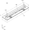
- FIGS. 1 and 2 are diagrams showing a configuration example of a tunable bandpass filter 100 according to the related art.
- FIG. 1 is a perspective view
- FIG. 2 is a bottom view.
- the tunable bandpass filter 100 according to the related technology includes a waveguide 11, a metal plate 12, a dielectric plate 130, and a support rod 14.
- the tunable bandpass filter 100 is a filter called a semi-coaxial filter or an evanescent mode filter.
- the waveguide 11 is a conductive rectangular waveguide.
- the waveguide 11 is divided into two members on a horizontal plane, and a plate-like metal plate 12 is sandwiched between the two members.
- the metal plate 12 is made of a plate-like conductor and extends in the longitudinal direction (x direction) of the waveguide 11.
- three resonance plates 121-1 to 121-3 and two input / output ports 122-1 to 122-2 are formed on the metal plate 12.
- resonance plates 121-1 to 121-3 may be simply referred to as “resonance plates 121”.
- input / output ports 122-1 to 122-2 may be simply referred to as “input / output ports 122”.
- the tunable bandpass filter 100 is a three-stage bandpass filter including three resonance plates 121-1 to 121-3.
- the number of stages of the tunable bandpass filter 100 is not limited to three but may be two or more.
- the resonance plates 121-1 to 121-3 have one end (plus y direction side) connected to the metal plate 12 and the other end (minus y direction side) an open end (that is, not in contact with other members). It is a plate-like resonator.
- the resonance plates 121-1 to 121-3 are housed in the waveguide 11, and are arranged in the longitudinal direction (x direction) of the waveguide 11 so that the side surfaces of the resonance plate 121 face each other.
- the resonance plates 121-1 to 121-3 operate so as to resonate at a resonance frequency determined by the shape, length (y direction), and the like.
- the input / output ports 122-1 to 122-2 are ports for inputting and outputting high-frequency signals.
- the input / output port 122-1 is connected to the resonance plate 121-1 by electromagnetic coupling, and the input / output port 122-2 is connected to the resonance plate 121-3 by electromagnetic coupling.
- One of the input / output ports 122-1 to 122-2 operates as an input port, and the other operates as an output port.
- a high-frequency signal is input to the input / output port 122-1 and within that passband of the tunable bandpass filter 100. Only the high-frequency signal is output from the input / output port 122-2.
- the dielectric plate 130 is made of a plate-like dielectric.
- the dielectric plate 130 extends in the longitudinal direction (x direction) of the waveguide 11, and the main surface (surface having the largest area) of the dielectric plate 130 faces the main surfaces of the resonance plates 121-1 to 121-3.
- the resonator plates 121-1 to 121-3 are arranged adjacent to each other.
- the support rods 14-1 and 14-2 are attached to both ends of the dielectric plate 130 in the x direction. Using a stepping motor (not shown) provided outside the tunable bandpass filter 100, the support rods 14-1 and 14-2 are moved in the vertical direction (that is, the z direction perpendicular to the main surface of the dielectric plate 130). ), The dielectric plate 130 can be moved in the vertical direction (z direction). Thus, the distance between the dielectric plate 130 and the resonance plates 121-1 to 121-3 is variable.
- the tunable bandpass filter 100 moves the dielectric plate 130 in the vertical direction (z direction) when changing the center frequency of the passband.
- the center frequency of the pass band increases as the dielectric plate 130 moves away from the resonance plates 121-1 to 121-3 (as the dielectric plate 130 moves upward (plus z direction)).
- the closer the dielectric plate 130 approaches the resonance plates 121-1 to 121-3 the more the dielectric plate 130 moves downward (minus z direction)
- the lower the center frequency of the pass band the center frequency of the pass band.
- the dielectric plate is arranged such that the main surface of the dielectric plate faces the main surface of the resonator, as in the tunable bandpass filter 100 according to the related art shown in FIGS.
- Patent Documents 1 and 2 disclose tunable bandpass filters that change the center frequency of the passband by moving a plate.
- the tunable bandpass filter disclosed in Patent Document 1 changes the center frequency of the passband by moving the dielectric plate in a direction perpendicular to and parallel to the main surface of the dielectric plate.
- the tunable bandpass filter disclosed in Patent Document 2 moves a tuning piece in a direction parallel to the main surface of a tuning piece corresponding to a dielectric plate, and a metal sheet formed on the tuning piece, and a metal plate
- the center frequency of the pass band is changed by changing the positional relationship with the window formed on the corresponding metal plate.
- the tunable bandpass filter 100 according to the related art shown in FIGS. 1 and 2 has a problem that the bandwidth of the passband varies greatly when the center frequency of the passband is changed. Hereinafter, this problem will be described in detail.
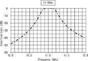
- FIGS. 3 to 5 are diagrams showing examples of passing waveforms of the tunable bandpass filter 100 according to the related art shown in FIGS. 1 and 2, in which the horizontal axis represents frequency [GHz] and the vertical axis represents pass. The loss [dB] is shown. 3, 4, and 5 are pass waveforms when the center frequencies of the passband are 10.6 [GHz], 11.0 [GHz], and 11.4 [GHz], respectively.
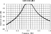
- FIG. 6 is a diagram in which the three passing waveforms shown in FIGS. 3 to 5 are superimposed so that the center frequencies match.
- FIG. 7 is a diagram illustrating an example of simulating the bandwidth characteristics of the tunable bandpass filter 100 according to the related technology illustrated in FIGS. 1 and 2 with respect to the center frequency of the passband.
- the horizontal axis represents the passband.
- the center frequency [GHz] and the vertical axis indicate the 3 dB bandwidth [MHz] of the pass band.
- the 3 dB bandwidth is a bandwidth at a point 3 dB lower than the peak of the passing waveform.
- 3 to 7 are designed under the condition that the number of filter stages is 3, the center frequency is 11.0 [GHz], the FRB (Full Ripple Band) is 200 [MHz], and the ripple is 0.01 [dB]. Simulates changing the center frequency.
- the tunable bandpass filter 100 As shown in FIGS. 3 to 7, the tunable bandpass filter 100 according to the related technique shown in FIGS. 1 and 2 has a center frequency of the passband of 10.6 [GHz] to 11.4 [GHz]. It can be seen that the bandwidth of the pass band fluctuates by 118 [MHz] when the frequency is changed to (change amount is 800 [MHz]).
- An object of the present disclosure is to solve the above-described problems and provide a tunable bandpass filter and a control method thereof that can suppress fluctuations in the bandwidth of the passband when the center frequency of the passband is changed. It is in.
- a tunable bandpass filter is A waveguide; A plurality of resonators housed in the waveguide and arranged in the longitudinal direction of the waveguide; A dielectric plate extending in the longitudinal direction of the waveguide and disposed adjacent to the plurality of resonators; A metal pattern for coupling adjustment formed at a position corresponding to the stage of the resonator in the dielectric plate, The distance between the dielectric plate and the resonator is variable.
- a method for controlling a tunable bandpass filter includes: In the waveguide, a plurality of resonators are arranged side by side in the longitudinal direction of the waveguide, A dielectric plate extending in the longitudinal direction of the waveguide is disposed adjacent to the plurality of resonators, Forming a metal pattern for coupling adjustment at a position corresponding to the stage of the resonator in the dielectric plate, The distance between the dielectric plate and the resonator is variable.
- FIG. 6 is a diagram in which three passing waveforms shown in FIGS.
- 3 to 5 are superimposed. It is a figure which shows the example which simulated the characteristic of the bandwidth with respect to the center frequency of a pass band of the tunable band pass filter which concerns on the related technique shown in FIG.1 and FIG.2. It is a figure which shows the example which simulated the characteristic of the coupling coefficient with respect to the center frequency of a pass band of the tunable band pass filter which concerns on the related technique shown in FIG.1 and FIG.2.
- 3 is a perspective view illustrating a configuration example of a tunable bandpass filter according to Embodiment 1.
- FIG. 3 is a bottom view showing a configuration example of a tunable bandpass filter according to Embodiment 1.
- FIG.9 and FIG.10 It is a bottom view which shows the structural example of the dielectric material board shown in FIG.9 and FIG.10. It is an enlarged side view which shows the structural example of the metal pattern vicinity of the tunable bandpass filter which concerns on Embodiment 1 shown in FIG.9 and FIG.10. It is an enlarged side view which shows the structural example of the metal pattern vicinity of the tunable bandpass filter which concerns on Embodiment 1 shown in FIG.9 and FIG.10. It is a bottom view which shows the structural example of the tunable bandpass filter used as the modification of the tunable bandpass filter which concerns on Embodiment 1 shown in FIG.9 and FIG.10.
- FIG. 20 is a view obtained by superimposing the three passage waveforms shown in FIGS. 17 to 19. It is a figure which shows the example which simulated the characteristic of the bandwidth with respect to the center frequency of a pass band of the tunable band pass filter which concerns on Embodiment 1 shown in FIG.9 and FIG.10.
- 6 is a perspective view showing a configuration example of a tunable bandpass filter according to Embodiment 2.
- FIG. 27 is a bottom view illustrating a configuration example of the dielectric plate illustrated in FIG. 26.
- FIG. 27 is a side view showing a configuration example of a tunable bandpass filter according to Embodiment 3 shown in FIG. 26.
- FIG. 27 is a side view showing a configuration example of a tunable bandpass filter according to Embodiment 3 shown in FIG. 26.
- FIG. 8 is a diagram illustrating an example of simulating the characteristics of the coupling coefficient with respect to the center frequency of the pass band of the tunable band pass filter 100 according to the related technique shown in FIGS. 1 and 2, and the horizontal axis represents the pass band.
- the center frequency [GHz] and the vertical axis indicate the coupling coefficient.
- the coupling coefficient indicates the coupling coefficient between the resonance plates 121
- the coupling coefficient k12 indicates the coupling coefficient between the resonance plates 121-1, 121-2
- the coupling coefficient k23 indicates the resonance plates 121-2, 121.
- the coupling coefficient between -3 is shown.
- the simulation conditions are the same as those in FIGS.
- the characteristics of the coupling coefficient with respect to the center frequency of the passband of the tunable bandpass filter 100 according to the related art shown in FIG. 1 and FIG. Indeed, the coupling coefficient is higher.
- the bandwidth characteristics with respect to the center frequency of the pass band are considered to rise to the right, that is, the higher the center frequency, the wider the bandwidth. .
- the characteristic of the coupling coefficient with respect to the center frequency of the pass band decreases downward along the dotted line shown in FIG. 8, that is, as the center frequency increases. It is necessary to make the characteristic that the coupling coefficient is low.
- the tunable bandpass filter according to each embodiment described below has a function of setting the characteristic of the coupling coefficient with respect to the center frequency of the passband to fall to the right, that is, the characteristic that the coupling coefficient decreases as the center frequency increases. Is provided.
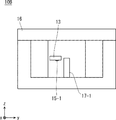
- FIGS. 9 and 10 are diagrams illustrating a configuration example of the tunable bandpass filter 10 according to the first embodiment, in which FIG. 9 is a perspective view and FIG. 10 is a bottom view.
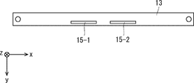
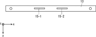
- FIG. 11 is a bottom view illustrating a configuration example of the dielectric plate 13 illustrated in FIGS. 9 and 10.
- the tunable bandpass filter 10 according to the first embodiment is more dielectric than the tunable bandpass filter 100 according to the related art shown in FIGS.
- a dielectric plate 13 provided with metallic metal patterns 15-1 to 15-2 for adjusting coupling is provided.
- metal patterns 15-1 to 15-2 are referred to without any particular distinction, they may be simply referred to as “metal patterns 15”.
- the metal patterns 15-1 to 15-2 are formed at positions corresponding to the steps of the resonance plate 121 on the main surface opposite to the resonance plate 121 of the two main surfaces of the dielectric plate 13.
- the metal pattern 15-1 is formed at a position corresponding to the step between the resonance plates 121-1 and 121-2
- the metal pattern 15-2 is a position corresponding to the step between the resonance plates 121-2 and 121-3. Is formed.
- FIGS. 12 and 13 are enlarged side views showing a configuration example in the vicinity of the metal pattern 15 of the tunable bandpass filter 10 according to the first embodiment shown in FIGS. 9 and 10.
- FIG. 12 shows a state in which the dielectric plate 13 approaches the resonance plate 121 (metal plate 12) (a state in which the dielectric plate 13 has moved downward (minus z direction)).
- FIG. The state (state in which the dielectric plate 13 has moved upward (plus z direction)) away from the resonance plate 121 (metal plate 12) is shown.
- the tunable bandpass filter 10 according to the first embodiment is similar to the tunable bandpass filter 100 according to the related art, as the dielectric plate 13 approaches the resonance plate 121 (metal plate 12), the center of the passband is increased. The center frequency of the pass band increases as the frequency decreases and the dielectric plate 13 moves away from the resonance plate 121 (metal plate 12).
- the tunable bandpass filter 10 according to the first embodiment can not only change the center frequency of the passband by moving the dielectric plate 13 in the vertical direction (z direction),
- the coupling coefficient can also be changed.
- the characteristic of the coupling coefficient with respect to the center frequency of the pass band can be reduced to the right, that is, the characteristic that the coupling coefficient decreases as the center frequency increases.
- FIG. 14 is a bottom view illustrating a configuration example of a tunable bandpass filter 10A that is a modification of the tunable bandpass filter 10 according to the first embodiment illustrated in FIGS. 9 and 10.
- the tunable band-pass filter 10A shown in FIG. 14 is arranged such that the positions in the y direction of the metal patterns 15-1 to 15-2 are more open than the tunable band-pass filter 10 shown in FIGS. It is close to the end side (minus y direction side).
- FIG. 15 shows the tunable bandpass filter 10 according to the first embodiment shown in FIGS. 9 and 10 and the tunable bandpass filter 10A according to the modification of the first embodiment shown in FIG. It is a figure which shows the example which simulated the characteristic of the coupling coefficient with respect to the center frequency of a zone
- FIG. 15 also shows the characteristics of the tunable bandpass filter 100 according to the related technique shown in FIGS. 1 and 2 for comparison.
- the horizontal axis, the vertical axis, and simulation conditions are the same as those in FIG.
- the characteristics of the coupling coefficient of the tunable bandpass filters 10 and 10A according to the first embodiment with respect to the center frequency of the passband are lower right, that is, the higher the center frequency, It can be seen that the characteristic is low. Further, when comparing the characteristics of the tunable bandpass filters 10 and 10A, the inclination becomes steeper as the metal patterns 15-1 to 15-2 are brought closer to the open end side (minus y direction side) of the resonance plate 121. Recognize.
- FIG. 16 shows the characteristic of the coupling coefficient with respect to the center frequency of the pass band of the tunable band pass filter 10 according to the first embodiment shown in FIGS. 9 and 10, and the characteristic of the dotted line (bandwidth) shown in FIG. It is a figure which shows the example compared with the characteristic of the coupling coefficient required when making is constant.
- the characteristic of the coupling coefficient of the tunable bandpass filter 10 according to the first embodiment with respect to the center frequency of the passband does not completely match the characteristic of the dotted line shown in FIG. It can be seen that the amount of deviation between the two characteristics is greatly improved.
- FIG. 17 to FIG. 19 are diagrams showing examples of simulating the pass waveform of the tunable bandpass filter 10 according to the first embodiment shown in FIG. 9 and FIG. 17, 18 and 19 are pass waveforms when the center frequency of the pass band is 10.6 [GHz], 11.0 [GHz] and 11.4 [GHz], respectively.
- FIG. 20 is a diagram in which the three passing waveforms shown in FIGS. 17 to 19 are overlapped so that the center frequencies coincide with each other.
- FIG. 21 is a diagram illustrating an example of simulating the bandwidth characteristics of the tunable bandpass filter 10 according to the first embodiment illustrated in FIGS. 9 and 10 with respect to the center frequency of the passband.
- FIG. 21 also shows the characteristics of the tunable bandpass filter 100 according to the related technology shown in FIGS. 1 and 2 for comparison.
- the horizontal axis, the vertical axis, and the simulation conditions are the same as those in FIGS.
- the tunable bandpass filter 100 changes the center frequency of the passband from 10.6 [GHz] to 11.4 [GHz] (the amount of change is 800 [MHz]. ]), And the passband bandwidth fluctuated by 118 [MHz].
- the tunable bandpass filter 10 according to the first embodiment has a center frequency of the passband of 10.6 [GHz] to 11.4 [GHz]. Even if it is changed, it can be seen that the fluctuation of the bandwidth of the pass band is suppressed to 25 [MHz].
- the tunable bandpass filters 10 and 10A according to the first embodiment correspond to the steps between the resonance plates 121 in the dielectric plate 13 arranged so as to be adjacent to the plurality of resonance plates 121.
- a metal pattern 15 is formed at the position.
- the metal pattern 15 acts on the coupling coefficient between the resonance plates 121. Specifically, when the dielectric plate 13 is close to the resonance plate 121, the center frequency of the pass band is low, and the coupling between the resonance plates 121 is strengthened via the metal pattern 15. Becomes higher. Further, when the dielectric plate 13 is moved away from the resonance plate 121, the center frequency of the pass band becomes high, and the influence of the metal pattern 15 between the resonance plates 121 becomes weak, so that the coupling coefficient becomes low.
- the characteristics of the coupling coefficient of the tunable bandpass filters 10 and 10A according to the first embodiment with respect to the center frequency of the passband are lower right, that is, the characteristic that the coupling coefficient is lower as the center frequency is higher. Become. Therefore, the tunable bandpass filters 10 and 10A according to the first embodiment can suppress fluctuations in the bandwidth of the passband when the center frequency of the passband is changed.
- the position of the metal pattern 15 in the length direction (y direction) of the resonance plate 121, the length of the metal pattern 15 (x direction), the shape of the metal pattern 15 and the like are shown in FIGS. It is not limited to what was shown in FIG.
- the length (x direction) of the metal pattern 15 may be shorter than the length shown in FIGS.
- the shape of the metal pattern 15 may be, for example, a rectangular shape. good.
- the position of the metal pattern 15 in the length direction (y direction) of the resonance plate 121 is not particularly limited, but from one end connected to the metal plate 12 of the resonance plate 121 to the open end. The position between the ends is preferred.
- the metal pattern 15 is formed on the main surface of the dielectric plate 13 facing the resonance plate 121, but the present invention is not limited to this.
- the metal pattern 15 may be formed on the main surface of the dielectric plate 13 opposite to the main surface facing the resonance plate 121.
- the metal pattern 15 has a strong influence on the coupling coefficient because the resonance plate 121 of the dielectric plate 13. It is the direction of the main surface opposite to. Therefore, the metal pattern 15 is preferably formed on the main surface of the dielectric plate 13 that faces the resonance plate 121.
- the position of the metal pattern 15 in the y direction, the length of the metal pattern 15 (x direction), the shape of the metal pattern 15, the main surface of the dielectric plate 13 forming the metal pattern 15, etc. are changed,
- the characteristic of the coupling coefficient with respect to the center frequency changes such as a change in slope. Therefore, the position of the metal pattern 15 in the y direction, the length of the metal pattern 15 (x direction), the shape of the metal pattern 15, the main surface of the dielectric plate 13 forming the metal pattern 15, etc. What is necessary is just to determine suitably according to a width
- the dielectric plate 13 is disposed so that the main surface of the dielectric plate 13 faces the main surface of the resonance plate 121, and the dielectric plate 13 is perpendicular to the main surface of the dielectric plate 13. It was an example of moving in the direction.
- the second embodiment is an example in which the moving direction of the dielectric plate 13 is different from the first embodiment.
- FIG. 22 is a perspective view showing a configuration example of the tunable bandpass filter 10B according to the second embodiment.
- FIG. 23 is a bottom view showing a configuration example of the dielectric plate 13 shown in FIG.
- the tunable bandpass filter 10 according to Embodiment 1 shown in FIGS. 9 and 10 plate-like resonance plates 121-1 to 121-3 are formed on the metal plate 12 sandwiched between the waveguides 11. It was a configuration.
- the tunable bandpass filter 10B according to the second embodiment includes rod-shaped resonance bars 17-1 to 17-3 inside the waveguide 16. Is provided.
- the resonance bars 17-1 to 17-3 are referred to without particular distinction, they may be simply referred to as “resonance bars 17”.
- One end (minus z direction side) of the resonance rods 17-1 to 17-3 is connected to the lower surface of the waveguide 16, and the other end (plus z direction side) is an open end (that is, is not in contact with other members).
- This is a rod-shaped resonator.
- the resonance bars 17-1 to 17-3 are housed in the waveguide 16 and are arranged in the longitudinal direction (x direction) of the waveguide 16.
- the resonance bars 17-1 to 17-3 operate so as to resonate at a resonance frequency determined by the shape, length (z direction), and the like.
- the dielectric plate 13 extends in the longitudinal direction (x direction) of the waveguide 16, and the resonance bars 17-1 to 17-1 are arranged so that the side surfaces of the dielectric plate 13 face the side surfaces of the resonance bars 17-1 to 17-3. Arranged adjacent to 17-3.
- the support rods 14-1 and 14-2 at both ends in the x direction of the dielectric plate 13 are displaced in the vertical direction (that is, the z direction perpendicular to the main surface of the dielectric plate 13) using a stepping motor (not shown). By doing so, the dielectric plate 13 moves in the vertical direction (z direction).
- the metal patterns 15-1 to 15-2 are formed at positions corresponding to the steps of the resonance rod 17 on the lower main surface of the two main surfaces of the dielectric plate 13.
- the metal pattern 15-1 is formed at a position corresponding to the stage between the resonance bars 17-1 and 17-2
- the metal pattern 15-2 is a position corresponding to the stage between the resonance bars 17-2 and 17-3. Is formed.
- FIG. 24 and 25 are side views showing a configuration example of the tunable bandpass filter 10B according to the second embodiment shown in FIG. 24 shows a state in which the dielectric plate 13 approaches the open end of the resonance bar 17 (a state in which the dielectric plate 13 has moved upward (plus z direction)), and FIG. 25 shows a state in which the dielectric plate 13 is in the resonance bar. 17 shows a state in which the dielectric plate 13 is moved downward (minus z direction) away from the open end of 17.
- the center frequency of the passband decreases as the dielectric plate 13 approaches the open end of the resonance bar 17, and the dielectric plate 13 The further away from the open end, the higher the center frequency of the passband.
- the characteristic of the coupling coefficient with respect to the center frequency of the passband decreases, that is, as the center frequency increases.
- the coupling coefficient can be reduced.
- the position of the metal pattern 15 in the y direction, the length of the metal pattern 15 (x direction), the shape of the metal pattern 15, and the metal pattern 15 are formed.
- the main surface and the like of the dielectric plate 13 are not limited to those shown in FIGS.
- the first embodiment is an example applied to a semi-coaxial filter or an evanescent mode filter.
- the third embodiment is an example applied to a TE (Transverse Electric) mode filter.
- FIG. 26 is a perspective view showing a configuration example of a tunable bandpass filter 10C according to the third embodiment.
- FIG. 27 is a bottom view showing a configuration example of the dielectric plate 13 shown in FIG.
- the tunable bandpass filter 10C according to the third embodiment is compared with the tunable bandpass filter 10 according to the first embodiment shown in FIGS. The difference is that a ladder-like metal plate 18 is provided instead of the metal plate 12.
- the metal plate 18 is made of a plate-like conductor and extends in the longitudinal direction (x direction) of the waveguide 11.
- the metal plate 18 has a ladder shape, and cavities 181-1 to 181-3 where no metal is present serve as a resonator.
- cavities 181-1 to 181-3 may be simply referred to as “cavity 181”.
- the dielectric plate 13 extends in the longitudinal direction (x direction) of the waveguide 16 so that the main surface of the dielectric plate 13 faces the main surface of the cavities 181-1 to 181-3 (metal plate 18).
- the cavity portions 181-1 to 181-3 are arranged adjacent to each other.
- the support rods 14-1 and 14-2 at both ends in the x direction of the dielectric plate 13 are displaced in the vertical direction (that is, the z direction perpendicular to the main surface of the dielectric plate 13) using a stepping motor (not shown). By doing so, the dielectric plate 13 moves in the vertical direction (z direction).
- the metal patterns 15-1 to 15-2 are formed on the lower principal surface of the two principal surfaces of the dielectric plate 13 at positions corresponding to the steps of the cavity 181.
- the metal pattern 15-1 is formed at a position corresponding to the space between the cavities 181-1 and 181-2
- the metal pattern 15-2 is a position corresponding to the space between the cavities 181-2 and 181-3. Is formed.
- FIG. 28 and 29 are side views showing a configuration example of the tunable bandpass filter 10C according to the third embodiment shown in FIG.
- FIG. 28 shows a state in which the dielectric plate 13 approaches the cavity 181 (metal plate 18) (the state in which the dielectric plate 13 has moved downward (minus z direction)), and FIG. The state (dielectric plate 13) has moved upward (plus z direction) away from the cavity 181 (metal plate 18).
- the characteristic of the coupling coefficient with respect to the center frequency of the passband decreases downward, that is, as the center frequency increases, as in the first embodiment.
- the coupling coefficient can be reduced.
- the position of the metal pattern 15 in the y direction, the length of the metal pattern 15 (x direction), the shape of the metal pattern 15, and the metal pattern 15 are formed.
- the main surface and the like of the dielectric plate 13 are not limited to those shown in FIGS.
- examples of the movement direction of the dielectric plate are shown.
- the movement direction of the dielectric plate is not limited to these examples.
- examples of the tunable bandpass filter include a semi-coaxial filter, an evanescent mode filter, and a TE mode filter.
- the resonance mode of the filter is limited to these examples. Is not to be done.
- the present disclosure can also be applied to other resonance modes (for example, a TEM (Transverse Electro Magnetic) mode).
Abstract
Un filtre passe-bande accordable (10) de la présente invention comprend : un guide d'ondes (11) ; une pluralité de résonateurs (121) qui sont placés dans le guide d'ondes (11) et agencés dans une direction longitudinale du guide d'ondes (11) ; une plaque diélectrique (13) qui s'étend dans la direction longitudinale du guide d'ondes (11) et qui est disposée de manière adjacente à la pluralité de résonateurs (121) ; et un motif métallique (15) destiné à un régler le couplage formé à une position sur la plaque diélectrique (13) correspondant au milieu des étages des résonateurs (121). La plaque diélectrique (13) a une distance variable entre les résonateurs (121).
Priority Applications (1)
| Application Number | Priority Date | Filing Date | Title |
|---|---|---|---|
| US17/042,362 US11152676B2 (en) | 2018-03-29 | 2019-02-18 | Tunable band-pass filter and control method therefor |
Applications Claiming Priority (2)
| Application Number | Priority Date | Filing Date | Title |
|---|---|---|---|
| JP2018-063980 | 2018-03-29 | ||
| JP2018063980 | 2018-03-29 |
Publications (1)
| Publication Number | Publication Date |
|---|---|
| WO2019187761A1 true WO2019187761A1 (fr) | 2019-10-03 |
Family
ID=68060315
Family Applications (1)
| Application Number | Title | Priority Date | Filing Date |
|---|---|---|---|
| PCT/JP2019/005726 WO2019187761A1 (fr) | 2018-03-29 | 2019-02-18 | Filtre passe-bande accordable et son procédé de commande |
Country Status (2)
| Country | Link |
|---|---|
| US (1) | US11152676B2 (fr) |
| WO (1) | WO2019187761A1 (fr) |
Families Citing this family (3)
| Publication number | Priority date | Publication date | Assignee | Title |
|---|---|---|---|---|
| JP2021190742A (ja) * | 2020-05-26 | 2021-12-13 | 日本電気株式会社 | 周波数可変フィルタ及び結合方法 |
| CN112952323A (zh) * | 2021-04-01 | 2021-06-11 | 昆山立讯射频科技有限公司 | 一种单体谐振杆、谐振杆及射频腔体滤波器 |
| WO2023122974A1 (fr) * | 2021-12-28 | 2023-07-06 | Telefonaktiebolaget Lm Ericsson (Publ) | Élément de résonance, élément de résonance en une pièce et filtre à cavité |
Citations (4)
| Publication number | Priority date | Publication date | Assignee | Title |
|---|---|---|---|---|
| US4761625A (en) * | 1986-06-20 | 1988-08-02 | Rca Corporation | Tunable waveguide bandpass filter |
| JP2001060805A (ja) * | 1999-08-20 | 2001-03-06 | Tokin Corp | 誘電体共振器及び誘電体フィルタ |
| WO2017170120A1 (fr) * | 2016-03-31 | 2017-10-05 | 日本電気株式会社 | Filtre passe-bande ajustable |
| US20170288289A1 (en) * | 2014-12-18 | 2017-10-05 | Huawei Technologies Co., Ltd. | Tunable filter |
Family Cites Families (1)
| Publication number | Priority date | Publication date | Assignee | Title |
|---|---|---|---|---|
| JP5187766B2 (ja) * | 2009-06-23 | 2013-04-24 | Necエンジニアリング株式会社 | チューナブル帯域通過フィルタ |
-
2019
- 2019-02-18 WO PCT/JP2019/005726 patent/WO2019187761A1/fr active Application Filing
- 2019-02-18 US US17/042,362 patent/US11152676B2/en active Active
Patent Citations (4)
| Publication number | Priority date | Publication date | Assignee | Title |
|---|---|---|---|---|
| US4761625A (en) * | 1986-06-20 | 1988-08-02 | Rca Corporation | Tunable waveguide bandpass filter |
| JP2001060805A (ja) * | 1999-08-20 | 2001-03-06 | Tokin Corp | 誘電体共振器及び誘電体フィルタ |
| US20170288289A1 (en) * | 2014-12-18 | 2017-10-05 | Huawei Technologies Co., Ltd. | Tunable filter |
| WO2017170120A1 (fr) * | 2016-03-31 | 2017-10-05 | 日本電気株式会社 | Filtre passe-bande ajustable |
Non-Patent Citations (1)
| Title |
|---|
| MIRA ET AL.: "Mechanical Tuning of Substrate Integrated Waveguide Filters", IEEE TRANSACTIONS ON MICROWAVE THEORY AND TECHNIQUES, vol. 63, no. 12, December 2015 (2015-12-01), pages 3939 - 3946, XP011592613, doi:10.1109/TMTT.2015.2490144 * |
Also Published As
| Publication number | Publication date |
|---|---|
| US20210028525A1 (en) | 2021-01-28 |
| US11152676B2 (en) | 2021-10-19 |
Similar Documents
| Publication | Publication Date | Title |
|---|---|---|
| US8884722B2 (en) | Inductive coupling in transverse electromagnetic mode | |
| JP4178264B2 (ja) | チューナブルフィルタ | |
| WO2019187761A1 (fr) | Filtre passe-bande accordable et son procédé de commande | |
| JP5187766B2 (ja) | チューナブル帯域通過フィルタ | |
| US6215376B1 (en) | Filter construction and oscillator for frequencies of several gigahertz | |
| US7710222B2 (en) | Dual band resonator and dual band filter | |
| US8836450B2 (en) | Adjustable resonator filter | |
| EP1447876A1 (fr) | Filtre et méthode d'arrangement des résonateurs | |
| WO2015079227A1 (fr) | Appareil à filtre de guide d'ondes en céramique et son procédé de fabrication et son utilisation | |
| US11056755B2 (en) | Microwave resonator | |
| KR101191751B1 (ko) | 입출력 포트를 이용하여 너치를 구현하는 rf캐비티 필터 | |
| CN112563702B (zh) | 基于hmsiw腔体的小型化双模滤波器及零点调节方法 | |
| CN113330633B (zh) | 微型天线滤波器及滤波器阵列 | |
| US20160240905A1 (en) | Hybrid folded rectangular waveguide filter | |
| WO2019017085A1 (fr) | Filtre passe-bande accordable et son procédé de configuration | |
| CN112072229B (zh) | 对角耦合盒型拓扑结构的四阶微带带通滤波器 | |
| US7274273B2 (en) | Dielectric resonator device, dielectric filter, duplexer, and high-frequency communication apparatus | |
| JP2016119531A (ja) | チューナブルエバネセントモード帯域通過フィルタ | |
| US7479856B2 (en) | High-frequency filter using coplanar line resonator | |
| US20140111289A1 (en) | Microwave Filter Having an Adjustable Bandwidth | |
| Tsai et al. | Hairpin filters with tunable transmission zeros | |
| US7482898B2 (en) | Dielectric filter, dielectric duplexer, and communication apparatus | |
| WO2017199766A1 (fr) | Filtre passe-bande et son procédé de commande | |
| KR19990014343A (ko) | 일체형 유전체 듀플렉서 | |
| KR102315196B1 (ko) | 유전체 도파관 필터 |
Legal Events
| Date | Code | Title | Description |
|---|---|---|---|
| 121 | Ep: the epo has been informed by wipo that ep was designated in this application |
Ref document number: 19774566 Country of ref document: EP Kind code of ref document: A1 |
|
| NENP | Non-entry into the national phase |
Ref country code: DE |
|
| 122 | Ep: pct application non-entry in european phase |
Ref document number: 19774566 Country of ref document: EP Kind code of ref document: A1 |
|
| NENP | Non-entry into the national phase |
Ref country code: JP |