WO2019187293A1 - 分離装置及び分離方法 - Google Patents
分離装置及び分離方法 Download PDFInfo
- Publication number
- WO2019187293A1 WO2019187293A1 PCT/JP2018/040586 JP2018040586W WO2019187293A1 WO 2019187293 A1 WO2019187293 A1 WO 2019187293A1 JP 2018040586 W JP2018040586 W JP 2018040586W WO 2019187293 A1 WO2019187293 A1 WO 2019187293A1
- Authority
- WO
- WIPO (PCT)
- Prior art keywords
- magnetic particles
- liquid
- coil
- magnetic
- wall
- Prior art date
- Legal status (The legal status is an assumption and is not a legal conclusion. Google has not performed a legal analysis and makes no representation as to the accuracy of the status listed.)
- Ceased
Links
Images



Classifications
-
- B—PERFORMING OPERATIONS; TRANSPORTING
- B03—SEPARATION OF SOLID MATERIALS USING LIQUIDS OR USING PNEUMATIC TABLES OR JIGS; MAGNETIC OR ELECTROSTATIC SEPARATION OF SOLID MATERIALS FROM SOLID MATERIALS OR FLUIDS; SEPARATION BY HIGH-VOLTAGE ELECTRIC FIELDS
- B03C—MAGNETIC OR ELECTROSTATIC SEPARATION OF SOLID MATERIALS FROM SOLID MATERIALS OR FLUIDS; SEPARATION BY HIGH-VOLTAGE ELECTRIC FIELDS
- B03C1/00—Magnetic separation
- B03C1/02—Magnetic separation acting directly on the substance being separated
- B03C1/04—Magnetic separation acting directly on the substance being separated with the material carriers in the form of trays or with tables
- B03C1/08—Magnetic separation acting directly on the substance being separated with the material carriers in the form of trays or with tables with non-movable magnets
-
- B—PERFORMING OPERATIONS; TRANSPORTING
- B03—SEPARATION OF SOLID MATERIALS USING LIQUIDS OR USING PNEUMATIC TABLES OR JIGS; MAGNETIC OR ELECTROSTATIC SEPARATION OF SOLID MATERIALS FROM SOLID MATERIALS OR FLUIDS; SEPARATION BY HIGH-VOLTAGE ELECTRIC FIELDS
- B03C—MAGNETIC OR ELECTROSTATIC SEPARATION OF SOLID MATERIALS FROM SOLID MATERIALS OR FLUIDS; SEPARATION BY HIGH-VOLTAGE ELECTRIC FIELDS
- B03C1/00—Magnetic separation
- B03C1/02—Magnetic separation acting directly on the substance being separated
- B03C1/28—Magnetic plugs and dipsticks
- B03C1/288—Magnetic plugs and dipsticks disposed at the outer circumference of a recipient
-
- B—PERFORMING OPERATIONS; TRANSPORTING
- B03—SEPARATION OF SOLID MATERIALS USING LIQUIDS OR USING PNEUMATIC TABLES OR JIGS; MAGNETIC OR ELECTROSTATIC SEPARATION OF SOLID MATERIALS FROM SOLID MATERIALS OR FLUIDS; SEPARATION BY HIGH-VOLTAGE ELECTRIC FIELDS
- B03C—MAGNETIC OR ELECTROSTATIC SEPARATION OF SOLID MATERIALS FROM SOLID MATERIALS OR FLUIDS; SEPARATION BY HIGH-VOLTAGE ELECTRIC FIELDS
- B03C1/00—Magnetic separation
- B03C1/02—Magnetic separation acting directly on the substance being separated
- B03C1/025—High gradient magnetic separators
- B03C1/031—Component parts; Auxiliary operations
- B03C1/033—Component parts; Auxiliary operations characterised by the magnetic circuit
- B03C1/0335—Component parts; Auxiliary operations characterised by the magnetic circuit using coils
-
- B—PERFORMING OPERATIONS; TRANSPORTING
- B03—SEPARATION OF SOLID MATERIALS USING LIQUIDS OR USING PNEUMATIC TABLES OR JIGS; MAGNETIC OR ELECTROSTATIC SEPARATION OF SOLID MATERIALS FROM SOLID MATERIALS OR FLUIDS; SEPARATION BY HIGH-VOLTAGE ELECTRIC FIELDS
- B03C—MAGNETIC OR ELECTROSTATIC SEPARATION OF SOLID MATERIALS FROM SOLID MATERIALS OR FLUIDS; SEPARATION BY HIGH-VOLTAGE ELECTRIC FIELDS
- B03C1/00—Magnetic separation
- B03C1/02—Magnetic separation acting directly on the substance being separated
- B03C1/30—Combinations with other devices, not otherwise provided for
-
- B—PERFORMING OPERATIONS; TRANSPORTING
- B01—PHYSICAL OR CHEMICAL PROCESSES OR APPARATUS IN GENERAL
- B01D—SEPARATION
- B01D29/00—Filters with filtering elements stationary during filtration, e.g. pressure or suction filters, not covered by groups B01D24/00 - B01D27/00; Filtering elements therefor
- B01D29/44—Edge filtering elements, i.e. using contiguous impervious surfaces
- B01D29/445—Bar screens
-
- B—PERFORMING OPERATIONS; TRANSPORTING
- B01—PHYSICAL OR CHEMICAL PROCESSES OR APPARATUS IN GENERAL
- B01D—SEPARATION
- B01D35/00—Filtering devices having features not specifically covered by groups B01D24/00 - B01D33/00, or for applications not specifically covered by groups B01D24/00 - B01D33/00; Auxiliary devices for filtration; Filter housing constructions
- B01D35/06—Filters making use of electricity or magnetism
-
- B—PERFORMING OPERATIONS; TRANSPORTING
- B03—SEPARATION OF SOLID MATERIALS USING LIQUIDS OR USING PNEUMATIC TABLES OR JIGS; MAGNETIC OR ELECTROSTATIC SEPARATION OF SOLID MATERIALS FROM SOLID MATERIALS OR FLUIDS; SEPARATION BY HIGH-VOLTAGE ELECTRIC FIELDS
- B03C—MAGNETIC OR ELECTROSTATIC SEPARATION OF SOLID MATERIALS FROM SOLID MATERIALS OR FLUIDS; SEPARATION BY HIGH-VOLTAGE ELECTRIC FIELDS
- B03C2201/00—Details of magnetic or electrostatic separation
- B03C2201/18—Magnetic separation whereby the particles are suspended in a liquid
Definitions
- the technology of the present disclosure relates to a separation device and a separation method.
- Japanese Patent Application Laid-Open No. 2010-115647 discloses a configuration in which magnetic particles are separated from a liquid by centrifugal force and magnetic force.
- Japanese Patent Application Laid-Open No. 2014-089210 discloses a configuration in which a magnetic particle is separated from a liquid by gravity and magnetic force by moving a container that contains the liquid containing the magnetic particles relative to the magnet. .
- the technique of the present disclosure is intended to provide a separation apparatus and a separation method that can separate magnetic particles from a liquid with a simple structure in consideration of the above facts.
- the separation device generates a magnetic field by energization, containing a liquid containing magnetic particles, and acts on the liquid containing magnetic particles by causing a magnetic force to act on the magnetic particles in a stationary state with respect to the containing unit.
- the coil causes the magnetic particles to act on the magnetic particles in a stationary state with respect to the accommodating portion, and moves the magnetic particles against the gravity acting on the liquid containing the magnetic particles, so that the magnetic Since the particles are separated from the liquid, a moving mechanism and a driving unit for moving the coil relative to the housing unit are not necessary.
- the magnetic particles can be separated from the liquid with a simple structure as compared with the structure in which the magnetic particles are separated from the liquid by moving the coil relative to the accommodating portion.
- the separation device may include a filter having an opening through which magnetic particles moving by magnetic force can pass.
- the magnetic particles and foreign matter can be separated by the filter.
- the separation device includes an inclined portion having an ascending gradient that rises from the accommodating portion, and the coil can separate the magnetic particles from the liquid by moving the magnetic particles obliquely upward on the inclined portions. Good.
- the ease of movement of the magnetic particles that are moved by the magnetic force of the coil can be adjusted according to the magnitude of the ascending slope of the inclined portion.
- the inclined portion may have liquid repellency that repels liquid.
- the separation device since the inclined portion has liquid repellency, the liquid smoothly flows down the inclined portion. For this reason, magnetic particles and liquid can be separated efficiently.
- the coil may cover the periphery of the inclined portion.
- the separation device it is possible to move the magnetic particles diagonally upward on the inclined portion by effectively applying magnetic force to the magnetic particles.
- the separation device may include a particle storage unit that stores magnetic particles separated from the liquid.
- the separation device in the case where the magnetic particles are separated from the liquid in the configuration in which there is no particle container and there is only a single container, for example, the liquid is removed from the container in a state where the magnetic particles are held in the container by a magnetic force or the like. Such operations are necessary.
- an operation such as removing the liquid from the storage unit while the magnetic particles are held in the storage unit by a magnetic force or the like becomes unnecessary.
- the coil may cover the periphery of the particle container.
- the magnetic particles can be moved to the particle accommodating portion by effectively applying a magnetic force to the magnetic particles.
- the separation device may include a detection unit that detects that magnetic particles are stored in the particle storage unit, and when the detection unit detects, the coil may stop the generation of the magnetic field.
- the separation device it is possible to suppress a situation where the coil stops generating the magnetic field before the magnetic particles are accommodated in the particle accommodating portion.
- the coil may separate the magnetic particles from the liquid by applying a strength to the magnetic force acting on the magnetic particles.
- the coil separates the magnetic force acting on the magnetic particles by increasing or decreasing the magnetic force, so that the magnetic particles caught in the moving path are retracted toward the housing portion by gravity, and then the magnetic The particles can be separated from the liquid.
- the separation method according to the tenth aspect is a liquid containing magnetic particles in which a magnetic force generated by energization of the coils is applied to the magnetic particles in a state where the coils are stationary with respect to the containing portion containing the liquid containing magnetic particles.
- the magnetic particles are separated from the liquid by moving the magnetic particles from the container against the gravity acting on the liquid crystal.
- the magnetic particles act by causing the magnetic force to act on the magnetic particles in a stationary state with respect to the accommodating portion, and moving the magnetic particles against gravity acting on the liquid containing the magnetic particles. Since the coil is separated from the liquid, a moving mechanism and a driving unit for moving the coil relative to the housing unit are not necessary.
- the magnetic particles can be separated from the liquid with a simple structure as compared with the separation method in which the magnetic particles are separated from the liquid by moving the coil relative to the accommodating portion.
- magnetic particles can be separated from a liquid with a simple structure.
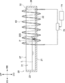
- FIG. 2 is a cross-sectional view (cross-sectional view taken along line 2-2 in FIG. 1) illustrating a schematic configuration of the separation apparatus according to the present embodiment. It is a top view which shows schematic structure of the container which concerns on this embodiment. It is a side view which shows schematic structure of the container which concerns on this embodiment.
- FIG. 2 it is sectional drawing which shows the state in which a magnetic particle passes a filter on an inclined wall.
- FIG. 2 it is sectional drawing which shows the state in which a magnetic particle falls from a horizontal wall to a 2nd bottom wall.
- FIG. 2 is sectional drawing which shows schematic structure of the container which concerns on a modification.
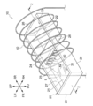
- FIG. 1 is a perspective view showing a schematic configuration of the separation apparatus 10.
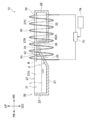
- FIG. 2 is a cross-sectional view (cross-sectional view taken along the line 2-2 in FIG. 1) showing a schematic configuration of the separation apparatus 10.
- the separation device 10 includes a container 20, a filter 40, a coil 60, a power source 70, a detection sensor 80 (see FIG. 7), and a control unit 74.
- the liquid L and the magnetic particles P and the specific configuration of each part (the container 20, the filter 40, the coil 60, the power source 70, the detection sensor 80, and the control unit 74) of the separation device 10 will be described.
- liquid L for example, a liquid containing an adsorbate that exhibits an adsorbing action on the magnetic particles P is used.
- a sample liquid containing a sample as an adsorbate is used.
- a sample solution containing DNA (deoxyribonucleic acid) released from cells as a sample is used.
- Magnetic particles P are particles that are attracted by magnetic force. Specifically, as the magnetic particles P, model number: Magnosphere ⁇ ⁇ MX100 / Carboxyl manufactured by JSR Corporation, model number: Magnosphere MS160 / Tosyl, and the like can be used.
- magnetic particles P magnetic particles having a particle size in the range of 0.01 ⁇ m to 10 ⁇ m are used.
- magnetic particles having a particle size of about 1 ⁇ m are used as the magnetic particles P.
- the liquid L may contain a surfactant for suppressing aggregation of the magnetic particles P.
- a surfactant for suppressing aggregation of the magnetic particles P for example, sodium dodecyl sulfate, polyoxyethylene sorbitan monolaurate (Tween 20), Triton X-100, or the like can be used.
- these surfactants may be used alone or in combination.
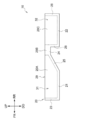
- FIG. 3 is a plan view showing a schematic configuration of the container 20.
- FIG. 4 is a side view showing a schematic configuration of the container 20.
- the container 20 shown in FIGS. 1, 2, 3 and 4 is a container for containing a liquid L containing magnetic particles P (see FIG. 5).
- the container 20 includes a first bottom wall 21, a front wall 23, an inclined wall 25 (an example of an inclined portion), a second bottom wall 22, The horizontal wall 24, the vertical wall 26, the rear wall 28, the left wall 27, the right wall 29, the storage portion 31, and the particle storage portion 32 are provided.
- the first bottom wall 21, the front wall 23, the inclined wall 25, the second bottom wall 22, the lateral wall 24, the vertical wall 26, the rear wall 28, the left wall 27, and the right wall 29 are integrally formed.
- the first bottom wall 21 forms the bottom of the front portion (front side portion) of the container 20, as shown in FIG.
- the first bottom wall 21 is formed in a plate shape whose vertical direction is the thickness direction.
- the front wall 23 is erected upward from the front end of the first bottom wall 21.
- the front wall 23 is formed in a plate shape whose front-rear direction is the thickness direction.
- the inclined wall 25 is an example of an inclined portion having an ascending gradient that rises from the accommodating portion. Specifically, the inclined wall 25 extends backward from the rear end of the first bottom wall 21. That is, the inclined wall 25 has an upward gradient that rises backward.
- the inclined wall 25 is formed in a plate shape whose thickness direction is the direction A in FIG.
- the inclined wall 25 has liquid repellency that repels the liquid L. Specifically, for example, by applying a coating agent such as a Daikin optool to the inclined wall 25, the inclined wall 25 has liquid repellency.
- the horizontal wall 24 extends rearward from the rear end of the inclined wall 25. Specifically, the horizontal wall 24 extends horizontally.
- the horizontal wall 24 is formed in a plate shape whose vertical direction is the thickness direction.
- the lateral wall 24 may have a slope that rises rearward smaller than the inclined wall 25. In addition, the lateral wall 24 may have a slope that falls downward.
- the vertical wall 26 extends downward from the rear end of the horizontal wall 24.
- the vertical wall 26 is formed in a plate shape whose thickness direction is the front-rear direction.
- the second bottom wall 22 extends rearward from the lower end of the vertical wall 26.
- the second bottom wall 22 forms the bottom of the rear portion (rear side portion) of the container 20.
- the second bottom wall 22 is formed in a plate shape whose vertical direction is the thickness direction.
- the rear wall 28 is erected upward from the rear end of the second bottom wall 22.
- the rear wall 28 is formed in a plate shape whose thickness direction is the front-rear direction.
- the left wall 27 is provided along the front-rear direction from the left end of the front wall 23 to the left end of the rear wall 28 as shown in FIG.
- the left wall 27 includes a front portion 27A, an intermediate portion 27B, and a rear portion 27C.
- the front portion 27 ⁇ / b> A is erected upward from the left end of the first bottom wall 21 and the left end of the inclined wall 25.
- the front end portion of the front portion 27 ⁇ / b> A is connected to the left end of the front wall 23.
- the intermediate portion 27B is an intermediate portion between the front portion 27A and the rear portion 27C, and is erected upward from the left end of the horizontal wall 24.
- the rear portion 27C is erected upward from the left end of the second bottom wall 22.
- the lower part of the front end portion of the rear portion 27 ⁇ / b> C is connected to the left end of the vertical wall 26.
- the rear end portion of the rear portion 27 ⁇ / b> C is connected to the left end of the rear wall 28.
- the right wall 29 is provided along the front-rear direction from the right end of the front wall 23 to the right end of the rear wall 28 as shown in FIG. As shown in FIG. 4, the right wall 29 has a front part 29A, an intermediate part 29B, and a rear part 29C.
- the front portion 29 ⁇ / b> A is erected upward from the right end of the first bottom wall 21 and the right end of the inclined wall 25.
- the front end portion of the front portion 29 ⁇ / b> A is connected to the right end of the front wall 23.
- the intermediate portion 29B is an intermediate portion between the front portion 29A and the rear portion 29C, and is erected upward from the right end of the lateral wall 24.
- the rear portion 29C is erected upward from the right end of the second bottom wall 22.
- the lower part of the front end portion of the rear portion 29 ⁇ / b> C is connected to the right end of the vertical wall 26.
- the rear end portion of the rear portion 29C is connected to the right end of the rear wall 28.
- the container 20 does not have the horizontal wall 24 and the intermediate portions 27B and 29B, the front ends of the rear portions 27C and 29C are connected to the rear end portions of the front portions 27A and 29A, and the upper end of the vertical wall 26 is the upper end of the inclined wall 25.
- the structure connected to may be sufficient.
- the storage unit 31 is an example of a storage unit that stores a liquid containing magnetic particles.
- This accommodating part 31 is comprised by the accommodation space which accommodates the liquid L containing the magnetic particle P (refer FIG. 5).
- the accommodating portion 31 is configured by an accommodating space provided in the front portion of the container 20. More specifically, the accommodating portion 31 is surrounded by the first bottom wall 21, the front wall 23, the inclined wall 25, the front portion 27A of the left wall 27, and the front portion 29A of the right wall 29. Consists of a storage space.
- the particle storage unit 32 is an example of a particle storage unit that stores magnetic particles separated from a liquid.
- grain storage part 32 is comprised by the storage space which accommodates the magnetic particle P isolate
- the particle storage portion 32 is configured by a storage space provided in the rear portion of the container 20. More specifically, the particle storage unit 32 is a storage unit surrounded by the second bottom wall 22, the vertical wall 26, the rear wall 28, the rear part 27 ⁇ / b> C of the left wall 27, and the rear part 29 ⁇ / b> C of the right wall 29. It is composed of space. Therefore, the particle container 32 is provided on the rear side with respect to the container 31.
- the filter 40 is an example of a filter having an opening through which magnetic particles moving by magnetic force can pass.
- the filter 40 is provided in the moving path of the magnetic particles P from the storage unit 31 to the particle storage unit 32. Specifically, the filter 40 is provided on the inclined wall 25.
- the filter 40 is formed in a comb shape. Specifically, the filter 40 is composed of a plurality of pins 42 (bar-shaped members) standing upward from the inclined wall 25. As shown in FIG. 3, the plurality of pins 42 are arranged along the left-right direction with a gap 43 through which the magnetic particles P can pass. The gap 43 functions as an opening through which the magnetic particles P moving by magnetic force can pass.
- the coil 60 shown in FIG. 2 generates a magnetic field by energization, causes a magnetic force to act on the magnetic particles in a stationary state with respect to the housing portion, and moves the magnetic particles from the housing portion against gravity acting on the liquid containing the magnetic particles.
- This is an example of a coil that separates magnetic particles from a liquid.
- the “stationary state with respect to the accommodating portion” means a state in which the moving portion is not moved relative to the accommodating portion. Therefore, not only the state in which the coil 60 moves but also the state in which the housing portion moves while the coil 60 is stationary does not correspond to the “stationary state with respect to the housing portion”.
- the coil 60 covers the periphery of the container 20 from the storage unit 31 to the particle storage unit 32 around an axis along the front-rear direction. Specifically, the coil 60 covers the periphery of the inclined wall 25, the horizontal wall 24, the vertical wall 26, the second bottom wall 22, the left wall 27, and the right wall 29 around an axis along the front-rear direction.
- the coil 60 is connected to a power source 70.
- the coil 60 generates a magnetic field when a current flows from the power source 70 and is energized.
- the direction of the magnetic field is formed in the direction of arrow B in FIG.
- the coil 60 is arranged such that the central portion 60 ⁇ / b> A in the axial direction (front-rear direction) where the magnetic force is maximum is located at the front side portion of the particle containing portion 32.
- the coil 60 is positioned with respect to the container 20. In other words, the coil 60 is configured not to move with respect to the container 20. Therefore, the coil 60 causes a magnetic force to act on the magnetic particles P in a stationary state with respect to the housing portion 31.
- the coil 60 separates the magnetic particles P from the liquid L by moving the magnetic particles P obliquely upward on the inclined wall 25 against the gravity acting on the liquid L containing the magnetic particles P.
- the magnetic particles P in the housing part 31 move by the magnetic force of the coil 60 as follows. That is, the magnetic particles P in the housing portion 31 move obliquely upward on the inclined wall 25 by the magnetic force of the coil 60 and pass through the filter 40 provided on the inclined wall 25 as shown in FIG. Further, the magnetic particles P that have passed through the filter 40 move on the lateral wall 24 and fall from the lateral wall 24 to the second bottom wall 22 as shown in FIG. Thereby, the magnetic particles P are accommodated in the particle accommodating portion 32.
- the configuration of the coil 60 is simplified, but the coils 60 are actually densely arranged in the front-rear direction, and the number of turns is larger than the number of turns shown.
- the detection sensor 80 shown in FIG. 7 is an example of a detection unit that detects that magnetic particles are stored in the particle storage unit.
- a detection sensor 80 for example, a non-contact type sensor that detects that the magnetic particles P are stored in the particle storage unit 32 without contact with the container 20 is used.
- an optical sensor using light as a non-contact type sensor is used.
- the detection sensor 80 for example, a reflection type optical sensor having a light emitting unit 80A and a light receiving unit 80B is used.
- the detection sensor 80 is accommodated in the particle accommodating portion 32 and the reflected light reflected by the second bottom wall 22 without the magnetic particle P being accommodated in the particle accommodating portion 32, for example. It is detected that the magnetic particles P are accommodated in the particle accommodating portion 32 based on a light amount difference from the reflected light reflected by the magnetic particles P.
- the detection sensor 80 is disposed, for example, above the particle container 32. Specifically, the detection sensor 80 is disposed, for example, in the front portion of the particle storage unit 32, that is, in the vicinity of the vertical wall 26.
- the detection result of the detection sensor 80 is output to the control unit 74 that controls on / off of the power source 70. And the control part 74 will turn off the power supply 70, if the detection result that the magnetic particle P was accommodated in the particle
- an optical sensor other than the reflection type for example, a transmission type optical sensor may be used.
- a non-contact type sensor that detects using static electricity may be used, and other methods may be used as long as it can be detected that the magnetic particles P are stored in the particle storage portion 32.
- controller 74 may control the power supply 70 so that the magnetic force applied to the magnetic particles P by the coil 60 is increased and separated from the liquid L. Specifically, for example, the control unit 74 switches the power supply 70 on and off a plurality of times, thereby increasing or decreasing the magnetic force that the coil 60 acts on the magnetic particles P.
- the controller 74 may change the value of the current that is passed through the coil 60 to increase or decrease the magnetic force of the coil 60.
- the strong state in which the magnetic force is strengthened and the weak state in which the magnetic force is weaker than the strong state As long as this happens.
- the weak state includes a state in which no magnetic force is generated, that is, a state in which energization to the coil 60 is stopped.
- This separation method has, for example, a preparation step and a separation step.
- each step is executed in the order of the preparation step and the separation step.
- each step of the separation method will be described.
- the preparation process includes an accommodation process and an arrangement process (set process).
- the liquid L containing the magnetic particles P is stored in the storage portion 31 of the container 20.
- the container 20 in which the liquid L is accommodated in the accommodating portion 31 is arranged (set) at a position (position shown in FIGS. 1 and 2) covered with the coil 60.
- the power supply 70 is turned on.
- the magnetic force acts on the magnetic particles P accommodated in the accommodating portion 31 in a state where the coil 60 is stationary with respect to the accommodating portion 31.
- the coil 60 moves the magnetic particles P in the accommodating portion 31 diagonally upward on the inclined wall 25 against the gravity acting on the liquid L containing the magnetic particles P, thereby causing the magnetic particles P to move to the liquid L.
- the magnetic particles P pass through the filter 40 when moving on the inclined wall 25 (see FIG. 5).
- the magnetic particles P that have passed through the filter 40 move on the lateral wall 24 and fall from the lateral wall 24 to the second bottom wall 22 (see FIG. 6). Thereby, the magnetic particles P are accommodated in the particle accommodating portion 32.
- the detection sensor 80 detects that the magnetic particles P moved from the storage unit 31 have been stored in the particle storage unit 32 (see FIG. 7), the power supply 70 is turned off and the coil 60 stops generating the magnetic field.
- the separation device 10 can be used in a polymerase chain reaction process. Specifically, for example, when separating the magnetic particles adsorbed with DNA from a mixed solution in which DNA (deoxyribonucleic acid) released from the cells is adsorbed on the magnetic particles and the DNA is mixed, the separation device 10 is used. Can be used.
- the coil 60 causes the magnetic particles P to act on the magnetic particles P in a stationary state with respect to the accommodating portion 31, and moves the magnetic particles P against the gravity acting on the liquid L containing the magnetic particles P. Since the magnetic particles P are separated from the liquid L, a moving mechanism and a driving unit for moving the coil 60 relative to the containing unit 31 are not necessary.
- the magnetic particles P can be separated from the liquid L with a simple structure as compared with the case where the magnetic particles P are separated from the liquid L by moving the coil 60 relative to the containing portion 31.
- the magnetic particles P separated from the liquid L are accommodated in the particle accommodating portion 32.
- the liquid L is held in a state where the magnetic particles P are held in the storage portion 31 by a magnetic force or the like.
- An operation such as removal from the accommodating portion 31 is required.
- the magnetic particles P separated from the liquid L are stored in the particle storage portion 32, the magnetic particles P are held in the storage portion 31 by a magnetic force or the like. Thus, an operation such as removing the liquid L from the storage unit 31 becomes unnecessary.
- the magnetic particles P are separated from the liquid L by moving the magnetic particles P obliquely upward on the inclined wall 25, so that the magnetic force of the coil 60 depends on the magnitude of the upward gradient of the inclined wall 25.
- the ease of movement of the moving magnetic particles P can be adjusted.
- the inclined wall 25 since the inclined wall 25 has liquid repellency, the liquid L smoothly flows down the inclined wall 25. For this reason, the magnetic particles P and the liquid L can be separated efficiently.
- the magnetic particles P pass through the filter 40 when moving on the inclined wall 25. Thereby, the magnetic particle P and the foreign material can be separated by the filter 40.
- the magnetic force of the coil 60 is made to act on the magnetic particle P efficiently, and the magnetic particle P on the inclination wall 25 is diagonally upward. Can be moved.
- the magnetic force of the coil 60 is efficiently applied to the magnetic particle P to move the magnetic particle P to the particle accommodating part 32. be able to.
- the detection sensor 80 is provided, and when the detection sensor 80 detects that the magnetic particles P are stored in the particle storage portion 32, the coil 60 stops generating the magnetic field. For this reason, before the magnetic particle P is accommodated in the particle
- the coil 60 separates the magnetic force acting on the magnetic particles P by increasing and decreasing the magnetic force, the magnetic particles P caught in the moving path are moved back toward the accommodating portion 31 by gravity, and then the magnetic particles P are liquidized. Can be separated from L.
- the filter 40 was provided on the inclined wall 25, it is not restricted to this.
- the filter 40 may be provided on the horizontal wall 24 and may be provided in the moving path of the magnetic particles P from the storage unit 31 to the particle storage unit 32.
- the filter 40 may be disposed at a position where the liquid L touches or a position where the liquid L is submerged in the storage unit 31.
- the structure in which the filter 40 is not provided may be sufficient.
- the filter 40 is formed in a comb shape, but is not limited thereto.
- the filter 40 may be, for example, a filter in which a plurality of holes are formed, and may be any filter as long as it has an opening through which magnetic particles P that move by magnetic force can pass.
- the inclined wall 25 is provided, but a configuration without the inclined wall 25 may be used.
- the configuration shown in FIG. 8 can be considered.
- the container 20 does not have the inclined wall 25, the horizontal wall 24, and the vertical wall 26 but has a partition wall 255.
- the partition wall 255 partitions the storage unit 31 and the particle storage unit 32.
- the partition wall 255 is erected upward between the first bottom wall 21 and the second bottom wall 22.
- the magnetic particles P are moved from the storage unit 31 to the particle storage unit 32 by passing the partition wall 255 by applying a magnetic force to the magnetic particles P in the storage unit 31.
- the coil 60 covers the periphery of the inclined wall 25, the horizontal wall 24, the vertical wall 26, and the second bottom wall 22 around the axis along the front-rear direction, but is not limited thereto.
- the coil 60 may not cover the periphery of the inclined wall 25, the horizontal wall 24, and the vertical wall 26.
- the coil 60 may cover the entire periphery of the container 20. That is, if the magnetic particle P can move from the accommodating part 31, the position which covers the container 20 is not ask
- the container 20 has the particle accommodating portion 32, but is not limited thereto.
- the separation device 10 may have a particle storage unit formed of a member different from the container 20.
Landscapes
- Chemical & Material Sciences (AREA)
- Chemical Kinetics & Catalysis (AREA)
- Apparatus Associated With Microorganisms And Enzymes (AREA)
- Investigating Or Analyzing Materials By The Use Of Magnetic Means (AREA)
Abstract
分離装置は、磁性粒子を含む液体を収容する収容部と、通電により磁場を発生させ、収容部に対する静止状態で磁性粒子に磁力を作用させ、磁性粒子を含む液体に作用する重力に抗して磁性粒子を収容部から移動させることで磁性粒子を液体から分離するコイルと、を備える。
Description
本開示の技術は、分離装置及び分離方法に関する。
特開2010-115647号公報には、遠心力と磁力により、液体から磁性粒子を分離する構成が開示されている。
特開2014-089210号公報には、磁性粒子を含んだ液体を収容する収容部を磁石に対して相対移動させることで、重力と磁力により、液体から磁性粒子を分離する構成が開示されている。
特開2010-115647号公報に開示されるように、遠心力と磁力を用いて液体から磁性粒子を分離する構成では、遠心力を発生させる回転部が必要となり、構造が複雑化する。
特開2014-089210号公報に開示されるように、収容部を磁石に対して相対移動させる構成では、移動機構や駆動部が必要となり、構造が複雑化する。
本開示の技術は、上記事実を考慮し、簡易な構造で、液体から磁性粒子を分離できる、分離装置及び分離方法を提供することを目的とする。
第1態様に係る分離装置は、磁性粒子を含む液体を収容する収容部と、通電により磁場を発生させ、収容部に対する静止状態で磁性粒子に磁力を作用させ、磁性粒子を含む液体に作用する重力に抗して磁性粒子を収容部から移動させることで磁性粒子を液体から分離するコイルと、を備える。
第1態様に係る分離装置によれば、コイルが、収容部に対する静止状態で磁性粒子に磁力を作用させ、磁性粒子を含む液体に作用する重力に抗して磁性粒子を移動させることで、磁性粒子を液体から分離するので、コイルを収容部に対して相対移動させる移動機構や駆動部が不要となる。
このため、コイルを収容部に対して相対移動させて磁性粒子を液体から分離する構成に比べ、簡易な構造で、液体から磁性粒子を分離できる。
第2態様に係る分離装置としては、磁力によって移動する磁性粒子が通過可能な開口を有するフィルタ、を備えていてもよい。
第2態様に係る分離装置によれば、フィルタによって磁性粒子と異物とを分離できる。
第3態様に係る分離装置としては、収容部から上る、上り勾配を有する傾斜部を備え、コイルは、磁性粒子を傾斜部上を斜め上側へ移動させることで磁性粒子を液体から分離してもよい。
第3態様に係る分離装置によれば、傾斜部の上り勾配の大きさによって、コイルの磁力により移動する磁性粒子の移動しやすさを調整できる。
第4態様に係る分離装置としては、傾斜部が、液体をはじく撥液性を有していてもよい。
第4態様に係る分離装置によれば、傾斜部が撥液性を有するので、液体がスムーズに傾斜部を流下する。このため、磁性粒子と液体とを効率的に分離できる。
第5態様に係る分離装置としては、コイルが、傾斜部の周囲を覆ってもよい。
第5態様に係る分離装置によれば、磁性粒子に磁力を効率的に作用させて、磁性粒子を傾斜部上を斜め上側へ移動させることができる。
第6態様に係る分離装置としては、液体から分離された磁性粒子を収容する粒子収容部を備えていてもよい。
ここで、粒子収容部がなく単一の収容部しかない構成において、液体から磁性粒子を分離する場合では、例えば、磁性粒子を収容部内において磁力等で保持した状態で液体を収容部から除去する等の操作が必要になる。これに対して、第6態様に係る分離装置によれば、磁性粒子を収容部内において磁力等で保持した状態で液体を収容部から除去する等の操作が不要となる。
第7態様に係る分離装置としては、コイルが、粒子収容部の周囲を覆ってもよい。
第7態様に係る分離装置によれば、磁性粒子に磁力を効率的に作用させて、磁性粒子を粒子収容部へ移動させることができる。
第8態様に係る分離装置としては、粒子収容部に磁性粒子が収容されたことを検知する検知部を備え、検知部が検知すると、コイルが、磁場の発生を停止してもよい。
第8態様に係る分離装置によれば、粒子収容部に磁性粒子が収容される前に、コイルが磁場の発生を停止する事態を抑制できる。
第9態様に係る分離装置としては、コイルが、磁性粒子に作用する磁力に強弱をつけて、磁性粒子を液体から分離してもよい。
第9態様に係る分離装置によれば、コイルが、磁性粒子に作用する磁力に強弱をつけて分離するので、移動経路中で引っ掛かった磁性粒子を重力で収容部側へ後退させてから、磁性粒子を液体から分離できる。
第10態様に係る分離方法は、磁性粒子を含む液体を収容する収容部に対してコイルを静止させた状態で、コイルが通電により発生させた磁力を磁性粒子に作用させ、磁性粒子を含む液体に作用する重力に抗して磁性粒子を収容部から移動させることで磁性粒子を液体から分離する。
第10態様に係る分離方法によれば、コイルが、収容部に対する静止状態で磁性粒子に磁力を作用させ、磁性粒子を含む液体に作用する重力に抗して磁性粒子を移動させることで磁性粒子を液体から分離するので、コイルを収容部に対して相対移動させる移動機構や駆動部が不要となる。
このため、コイルを収容部に対して相対移動させて磁性粒子を液体から分離する分離方法に比べ、簡易な構造で、液体から磁性粒子を分離できる。
本開示の技術によれば、簡易な構造で、液体から磁性粒子を分離することができる。
以下に、本発明に係る実施形態の一例を図面に基づき説明する。なお、以下の説明で用いる前方、後方、上方、下方、左方及び右方は、それぞれ、各図において「FR」、「RR」、「UP」、「DO」、「LH」、「RH」にて示す矢印方向に対応する。これらの方向は、説明の便宜上定めた方向であるから、装置構成がこれらの方向に限定されるものではない。
(分離装置10)
本実施形態に係る分離装置10について説明する。図1は、分離装置10の概略構成を示す斜視図である。図2は、分離装置10の概略構成を示す断面図(図1の2-2線断面図)である。
本実施形態に係る分離装置10について説明する。図1は、分離装置10の概略構成を示す斜視図である。図2は、分離装置10の概略構成を示す断面図(図1の2-2線断面図)である。
図1に示される分離装置10は、磁性粒子P(図5参照)を含む液体Lから磁性粒子Pを分離する装置である。具体的には、分離装置10は、図2に示されるように、容器20と、フィルタ40と、コイル60と、電源70と、検知センサ80(図7参照)と、制御部74と、を有している。以下、液体L及び磁性粒子Pと、分離装置10の各部(容器20、フィルタ40、コイル60、電源70、検知センサ80、及び制御部74)の具体的な構成と、について説明する。
(液体L及び磁性粒子P)
液体Lとしては、例えば、磁性粒子Pに対して吸着作用を示す吸着物を含む液体が用いられる。具体的には、液体Lとして、例えば、吸着物としての検体を含む検体液が用いられる。さらに具体的には、液体Lとして、例えば、細胞から遊離されたDNA(デオキシリボ核酸)を検体として含む検体液が用いられる。
液体Lとしては、例えば、磁性粒子Pに対して吸着作用を示す吸着物を含む液体が用いられる。具体的には、液体Lとして、例えば、吸着物としての検体を含む検体液が用いられる。さらに具体的には、液体Lとして、例えば、細胞から遊離されたDNA(デオキシリボ核酸)を検体として含む検体液が用いられる。
磁性粒子Pは、磁力によって引き寄せられる粒子である。具体的には、磁性粒子Pとして、JSR(株)社製 型番:Magnosphere MX100/Carboxylや、型番:Magnosphere MS160/Tosyl、等を用いることが可能である。
また、磁性粒子Pとしては、0.01μm以上10μm以下の範囲の粒径を有する磁性粒子が用いられる。好ましくは、磁性粒子Pとして、1μm程度の粒径を有する磁性粒子が用いられる。
液体Lは、磁性粒子Pの凝集を抑制するための界面活性剤を含んでいてもよい。磁性粒子Pの凝集を抑制するための界面活性剤としては、例えば、ドデシル硫酸ナトリウム、モノラウリン酸ポリオキシエチレンソルビタン(Tween20)、TritonX-100等を用いることができる。なお、これらの界面活性剤は、単独で用いてもよいし、複数を混合してから用いてもよい。
(容器20)
図3は、容器20の概略構成を示す平面図である。図4は、容器20の概略構成を示す側面図である。
図3は、容器20の概略構成を示す平面図である。図4は、容器20の概略構成を示す側面図である。
図1、図2、図3及び図4に示される容器20は、磁性粒子P(図5参照)を含む液体Lを収容する容器である。具体的には、図1及び図3に示されるように、容器20は、第一底壁21と、前壁23と、傾斜壁25(傾斜部の一例)と、第二底壁22と、横壁24と、縦壁26と、後壁28と、左壁27と、右壁29と、収容部31と、粒子収容部32と、を有している。第一底壁21、前壁23、傾斜壁25、第二底壁22、横壁24、縦壁26、後壁28、左壁27及び、右壁29は、一体に形成されている。
第一底壁21は、図2に示されるように、容器20の前部(前方側の部分)の底をなしている。この第一底壁21は、上下方向を厚み方向とする板状に形成されている。
前壁23は、第一底壁21の前端から上方へ立設されている。この前壁23は、前後方向を厚み方向とする板状に形成されている。
傾斜壁25は、収容部から上る上り勾配を有する傾斜部の一例である。具体的には、傾斜壁25は、第一底壁21の後端から後ろ上がりに延出されている。すなわち、傾斜壁25は、後ろ上がりの上り勾配を有している。この傾斜壁25は図2のA方向を厚み方向とする板状に形成されている。
傾斜壁25は、液体Lをはじく撥液性を有している。具体的には、例えば、ダイキン製オプツールなどのコーティング剤を傾斜壁25に塗布することで、傾斜壁25に撥液性を持たせる。
横壁24は、傾斜壁25の後端から後方へ延出されている。具体的には、横壁24は、水平に延出されている。この横壁24は、上下方向を厚み方向とする板状に形成されている。なお、横壁24は、傾斜壁25よりも小さい後ろ上がりの勾配を有してもよい。また、横壁24は、後ろ下がりの勾配を有していてもよい。
縦壁26は、横壁24の後端から下方へ延出されている。この縦壁26は、前後方向を厚み方向とする板状に形成されている。
第二底壁22は、縦壁26の下端から後方へ延出されている。この第二底壁22は、容器20の後部(後方側の部分)の底をなしている。第二底壁22は、上下方向を厚み方向とする板状に形成されている。
後壁28は、第二底壁22の後端から上方へ立設されている。この後壁28は、前後方向を厚み方向とする板状に形成されている。
左壁27は、図3に示されるように、前壁23の左端から後壁28の左端にわたって前後方向に沿って設けられている。左壁27は、図2に示されるように、前部27Aと、中間部27Bと、後部27Cと、を有している。前部27Aは、第一底壁21の左端及び傾斜壁25の左端から上方へ立設されている。前部27Aの前端部は、前壁23の左端に接続されている。中間部27Bは、前部27Aと後部27Cとの中間の部分であり、横壁24の左端から上方へ立設されている。
後部27Cは、第二底壁22の左端から上方へ立設されている。後部27Cの前端部の下側部分は、縦壁26の左端に接続されている。後部27Cの後端部は、後壁28の左端に接続されている。
右壁29は、図3に示されるように、前壁23の右端から後壁28の右端にわたって前後方向に沿って設けられている。右壁29は、図4に示されるように、前部29Aと、中間部29Bと、後部29Cと、を有している。前部29Aは、第一底壁21の右端及び傾斜壁25の右端から上方へ立設されている。前部29Aの前端部は、前壁23の右端に接続されている。中間部29Bは、前部29Aと後部29Cとの中間の部分であり、横壁24の右端から上方へ立設されている。
後部29Cは、第二底壁22の右端から上方へ立設されている。後部29Cの前端部の下側部分は、縦壁26の右端に接続されている。後部29Cの後端部は、後壁28の右端に接続されている。
なお、容器20は、横壁24及び中間部27B、29Bを有せず、後部27C、29Cの前端が前部27A、29Aの後端部に接続され、縦壁26の上端が傾斜壁25の上端に接続される構成であってもよい。
収容部31は、磁性粒子を含む液体を収容する収容部の一例である。この収容部31は、磁性粒子P(図5参照)を含む液体Lを収容する収容空間で構成されている。具体的には、収容部31は、容器20の前部に設けられた収容空間で構成されている。さらに具体的には、収容部31は、第一底壁21と、前壁23と、傾斜壁25と、左壁27の前部27Aと、右壁29の前部29Aと、で囲まれた収容空間で構成されている。
粒子収容部32は、液体から分離された磁性粒子を収容する粒子収容部の一例である。この粒子収容部32は、液体Lから分離された磁性粒子Pを収容する収容空間で構成されている(図6参照)。具体的には、粒子収容部32は、容器20の後部に設けられた収容空間で構成されている。さらに具体的には、粒子収容部32は、第二底壁22と、縦壁26と、後壁28と、左壁27の後部27Cと、右壁29の後部29Cと、で囲まれた収容空間で構成されている。したがって、粒子収容部32は、収容部31に対する後方側に設けられている。
(フィルタ40)
フィルタ40は、磁力によって移動する磁性粒子が通過可能な開口を有するフィルタの一例である。このフィルタ40は、収容部31から粒子収容部32までの磁性粒子Pの移動経路中に設けられている。具体的には、フィルタ40は、傾斜壁25上に設けられている。
フィルタ40は、磁力によって移動する磁性粒子が通過可能な開口を有するフィルタの一例である。このフィルタ40は、収容部31から粒子収容部32までの磁性粒子Pの移動経路中に設けられている。具体的には、フィルタ40は、傾斜壁25上に設けられている。
また、フィルタ40は、くし状に形成されている。具体的には、フィルタ40は、傾斜壁25から上方へ立設された複数のピン42(棒状部材)で構成されている。複数のピン42は、図3に示されるように、磁性粒子Pが通過可能な隙間43を有した状態で左右方向に沿って配置されている。この隙間43が、磁力によって移動する磁性粒子Pが通過可能な開口として機能する。
(コイル60及び電源70)
図2に示されるコイル60は、通電により磁場を発生させ、収容部に対する静止状態で磁性粒子に磁力を作用させ、磁性粒子を含む液体に作用する重力に抗して磁性粒子を収容部から移動させることで磁性粒子を液体から分離するコイルの一例である。
図2に示されるコイル60は、通電により磁場を発生させ、収容部に対する静止状態で磁性粒子に磁力を作用させ、磁性粒子を含む液体に作用する重力に抗して磁性粒子を収容部から移動させることで磁性粒子を液体から分離するコイルの一例である。
なお、「収容部に対する静止状態」とは、収容部に対して相対移動していない状態をいう。したがって、コイル60が移動する状態だけでなく、コイル60が静止した状態において収容部が移動する状態も「収容部に対する静止状態」に該当しない。
コイル60は、容器20における収容部31から粒子収容部32までの周囲を前後方向に沿った軸線周りに覆っている。具体的には、コイル60は、傾斜壁25、横壁24、縦壁26、第二底壁22、左壁27及び右壁29の周囲を前後方向に沿った軸線周りに覆っている。
コイル60は、電源70に接続されている。コイル60は、電源70から電流が流れて通電することで、磁場を発生させる。この磁場の向きは、コイル60内において、図2の矢印B方向に形成される。また、コイル60は、磁力が最大となる軸方向(前後方向)の中央部60Aが粒子収容部32の前方側部分に位置するように、配置されている。
コイル60は、容器20に対して位置決めされている。換言すれば、コイル60は、容器20に対して移動しない構成とされている。したがって、コイル60が収容部31に対する静止状態で磁性粒子Pに磁力を作用させる。そして、コイル60は、磁性粒子Pを含む液体Lに作用する重力に抗して、磁性粒子Pを傾斜壁25上を斜め上側へ移動させることで磁性粒子Pを液体Lから分離する。
具体的には、収容部31内の磁性粒子Pは、以下のように、コイル60の磁力により、移動する。すなわち、収容部31内の磁性粒子Pは、コイル60の磁力により、傾斜壁25上を斜め上側へ移動し、図5に示されるように、傾斜壁25に設けられたフィルタ40を通過する。さらに、フィルタ40を通過した磁性粒子Pは、横壁24を移動し、図6に示されるように、横壁24から第二底壁22へ落下する。これにより、磁性粒子Pは、粒子収容部32に収容される。
なお、図1及び図2では、コイル60の構成を簡略化しているが、コイル60は、実際には前後方向に密に配置され、巻き数も図示の巻き数よりも多くなっている。
(検知センサ80及び制御部74)
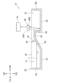
図7に示される検知センサ80は、粒子収容部に磁性粒子が収容されたことを検知する検知部の一例である。この検知センサ80には、例えば、容器20に対して非接触で、粒子収容部32に磁性粒子Pが収容されたことを検知する非接触型のセンサが用いられる。具体的には、検知センサ80として、例えば、非接触型のセンサとしての、光を用いた光センサが用いられる。
図7に示される検知センサ80は、粒子収容部に磁性粒子が収容されたことを検知する検知部の一例である。この検知センサ80には、例えば、容器20に対して非接触で、粒子収容部32に磁性粒子Pが収容されたことを検知する非接触型のセンサが用いられる。具体的には、検知センサ80として、例えば、非接触型のセンサとしての、光を用いた光センサが用いられる。
さらに具体的には、検知センサ80として、例えば、発光部80Aと受光部80Bとを有する反射型の光センサが用いられる。反射型の光センサを用いた場合では、検知センサ80は、例えば、粒子収容部32に磁性粒子Pが収容されずに第二底壁22で反射した反射光と、粒子収容部32に収容された磁性粒子Pで反射した反射光と、の光量差によって粒子収容部32に磁性粒子Pが収容されたことを検知する。
検知センサ80は、例えば、粒子収容部32の上方に配置されている。具体的には、検知センサ80は、例えば、粒子収容部32における前方側部分、すなわち、縦壁26の近傍に配置されている。
検知センサ80の検知結果は、電源70のオンオフを制御する制御部74に出力される。そして、制御部74は、粒子収容部32に磁性粒子Pが収容されたという検知結果を取得すると、電源70を切る。すなわち、検知センサ80が粒子収容部32に磁性粒子Pが収容されたことを検知すると、コイル60は磁場の発生を停止する。
なお、検知センサ80としては、反射型以外の光センサ、例えば透過型の光センサを用いてもよい。また、検知センサ80としては、静電気を用いて検知する非接触型のセンサを用いてもよく、粒子収容部32に磁性粒子Pが収容されたことを検知できれば他の方式を用いてもよい。
なお、コイル60が磁性粒子Pに作用する磁力に強弱をつけて磁性粒子Pを液体Lから分離するように、制御部74が電源70を制御してもよい。具体的には、例えば、制御部74が、電源70のオンオフを複数回切り替えることで、コイル60が磁性粒子Pに作用する磁力に強弱をつける。
なお、制御部74は、コイル60に通電させる電流値を変えることで、コイル60の磁力に強弱をつけてもよく、磁力を強めた強状態と、強状態よりも磁力を弱めた弱状態と、が生じればよい。弱状態には、磁力が生じていない状態、すなわち、コイル60への通電が停止した状態が含まれる。
(分離方法)
次に、分離装置10を用いて、磁性粒子Pを含む液体Lから磁性粒子Pを分離する分離方法について説明する。
次に、分離装置10を用いて、磁性粒子Pを含む液体Lから磁性粒子Pを分離する分離方法について説明する。
本分離方法は、例えば、準備工程と、分離工程と、を有している。本分離方法では、準備工程、分離工程の順で、各工程が実行される。以下、本分離方法の各工程について説明する。
(準備工程)
準備工程は、収容工程と、配置工程(セット工程)と、を有している。収容工程では、容器20の収容部31に、磁性粒子Pを含む液体Lを収容する。配置工程では、液体Lが収容部31に収容された容器20を、コイル60に覆われる位置(図1及び図2に示される位置)に配置する(セットする)。
準備工程は、収容工程と、配置工程(セット工程)と、を有している。収容工程では、容器20の収容部31に、磁性粒子Pを含む液体Lを収容する。配置工程では、液体Lが収容部31に収容された容器20を、コイル60に覆われる位置(図1及び図2に示される位置)に配置する(セットする)。
(分離工程)
分離工程では、電源70を入れる。これにより、コイル60が収容部31に対する静止状態で、収容部31に収容された磁性粒子Pに磁力を作用させる。そして、コイル60は、磁性粒子Pを含む液体Lに作用する重力に抗して、収容部31内の磁性粒子Pを傾斜壁25上を斜め上側へ移動させることで、磁性粒子Pを液体Lから分離する。磁性粒子Pは傾斜壁25を移動する際にフィルタ40を通過する(図5参照)。フィルタ40を通過した磁性粒子Pは、横壁24を移動し、横壁24から第二底壁22へ落下する(図6参照)。これにより、磁性粒子Pは、粒子収容部32に収容される。
分離工程では、電源70を入れる。これにより、コイル60が収容部31に対する静止状態で、収容部31に収容された磁性粒子Pに磁力を作用させる。そして、コイル60は、磁性粒子Pを含む液体Lに作用する重力に抗して、収容部31内の磁性粒子Pを傾斜壁25上を斜め上側へ移動させることで、磁性粒子Pを液体Lから分離する。磁性粒子Pは傾斜壁25を移動する際にフィルタ40を通過する(図5参照)。フィルタ40を通過した磁性粒子Pは、横壁24を移動し、横壁24から第二底壁22へ落下する(図6参照)。これにより、磁性粒子Pは、粒子収容部32に収容される。
収容部31から移動した磁性粒子Pが粒子収容部32に収容されたことが検知センサ80に検知されると(図7参照)、電源70が切られ、コイル60は磁場の発生を停止する。
(分離装置10の具体的な使用例)
分離装置10は、ポリメラーゼ連鎖反応の処理において用いることができる。具体的には、例えば、細胞から遊離されたDNA(デオキシリボ核酸)を磁性粒子に吸着させ、DNAが混合された混合液から、DNAが吸着された磁性粒子を分離する際に、分離装置10を用いることができる。
分離装置10は、ポリメラーゼ連鎖反応の処理において用いることができる。具体的には、例えば、細胞から遊離されたDNA(デオキシリボ核酸)を磁性粒子に吸着させ、DNAが混合された混合液から、DNAが吸着された磁性粒子を分離する際に、分離装置10を用いることができる。
(本実施形態の作用効果)
本実施形態によれば、コイル60が、収容部31に対する静止状態で磁性粒子Pに磁力を作用させ、磁性粒子Pを含む液体Lに作用する重力に抗して磁性粒子Pを移動させることで、磁性粒子Pを液体Lから分離するので、コイル60を収容部31に対して相対移動させる移動機構や駆動部が不要となる。
本実施形態によれば、コイル60が、収容部31に対する静止状態で磁性粒子Pに磁力を作用させ、磁性粒子Pを含む液体Lに作用する重力に抗して磁性粒子Pを移動させることで、磁性粒子Pを液体Lから分離するので、コイル60を収容部31に対して相対移動させる移動機構や駆動部が不要となる。
このため、コイル60を収容部31に対して相対移動させて磁性粒子Pを液体Lから分離する場合に比べ、簡易な構造で、液体Lから磁性粒子Pを分離できる。
また、本実施形態では、液体Lから分離された磁性粒子Pが粒子収容部32に収容される。ここで、粒子収容部32がなく収容部31しかない構成において、液体Lから磁性粒子Pを分離する場合では、例えば、磁性粒子Pを収容部31内において磁力等で保持した状態で液体Lを収容部31から除去する等の操作が必要になる。これに対して、本実施形態では、前述のように、液体Lから分離された磁性粒子Pが粒子収容部32に収容されるので、磁性粒子Pを収容部31内において磁力等で保持した状態で液体Lを収容部31から除去する等の操作が不要となる。
また、本実施形態では、磁性粒子Pを傾斜壁25上を斜め上側へ移動させることで磁性粒子Pを液体Lから分離するので、傾斜壁25の上り勾配の大きさによって、コイル60の磁力により移動する磁性粒子Pの移動しやすさを調整できる。
また、本実施形態では、傾斜壁25が撥液性を有するので、液体Lがスムーズに傾斜壁25を流下する。このため、磁性粒子Pと液体Lとを効率的に分離できる。
また、本実施形態では、磁性粒子Pは傾斜壁25を移動する際にフィルタ40を通過する。これにより、フィルタ40によって磁性粒子Pと異物とを分離できる。
また、本実施形態では、コイル60は、傾斜壁25の周囲を覆っているので、磁性粒子Pにコイル60の磁力を効率的に作用させて、磁性粒子Pを傾斜壁25上を斜め上側へ移動させることができる。
さらに、本実施形態では、コイル60は、粒子収容部32の周囲を覆っているので、磁性粒子Pにコイル60の磁力を効率的に作用させて、磁性粒子Pを粒子収容部32へ移動させることができる。
また、本実施形態では、検知センサ80が設けられており、検知センサ80が粒子収容部32に磁性粒子Pが収容されたことを検知すると、コイル60は磁場の発生を停止する。このため、粒子収容部32に磁性粒子Pが収容される前に、コイル60が磁場の発生を停止する事態を抑制できる。
また、コイル60が、磁性粒子Pに作用する磁力に強弱をつけて分離する場合では、移動経路中で引っ掛かった磁性粒子Pを重力で収容部31側へ後退させてから、磁性粒子Pを液体Lから分離できる。
(変形例)
本実施形態では、フィルタ40が傾斜壁25上に設けられていたが、これに限られない。フィルタ40は、例えば、横壁24上に設けられていてもよく、収容部31から粒子収容部32までの磁性粒子Pの移動経路中に設けられていればよい。また、フィルタ40は、収容部31において、液体Lが触れる位置、又は液体Lに水没する位置に配置されていてもよい。さらに、フィルタ40が設けられていない構成であってもよい。
本実施形態では、フィルタ40が傾斜壁25上に設けられていたが、これに限られない。フィルタ40は、例えば、横壁24上に設けられていてもよく、収容部31から粒子収容部32までの磁性粒子Pの移動経路中に設けられていればよい。また、フィルタ40は、収容部31において、液体Lが触れる位置、又は液体Lに水没する位置に配置されていてもよい。さらに、フィルタ40が設けられていない構成であってもよい。
また、本実施形態では、フィルタ40は、くし状に形成されていたが、これに限られない。フィルタ40としては、例えば、複数の孔が形成されたフィルタであってもよく、磁力によって移動する磁性粒子Pが通過可能な開口を有するものであればよい。
本実施形態では、傾斜壁25が設けられていたが、傾斜壁25を有さない構成であってもよい。この構成としては、例えば、図8に示される構成が考えられる。図8に示される構成では、容器20は、傾斜壁25、横壁24及び縦壁26を有しておらず、仕切壁255を有している。仕切壁255は、収容部31と粒子収容部32とを仕切っている。この仕切壁255は、第一底壁21と第二底壁22との間で上方へ立設されている。そして、図8に示される構成では、収容部31内の磁性粒子Pに磁力を作用させることで、磁性粒子Pを仕切壁255を越えさせることで収容部31から粒子収容部32へ移動させる。
本実施形態では、コイル60が、傾斜壁25、横壁24、縦壁26及び第二底壁22の周囲を前後方向に沿った軸線周りに覆っていたが、これに限られない。例えば、コイル60は、傾斜壁25、横壁24及び縦壁26の周囲を覆っていなくてもよい。また、コイル60は、容器20の全体の周囲を覆っていてもよい。すなわち、コイル60は、磁性粒子Pが収容部31から移動できれば、容器20を覆う位置は不問である。
本実施形態では、容器20が粒子収容部32を有していたが、これに限られない。分離装置10としては、例えば、容器20とは別部材で構成された粒子収容部を有していてもよい。
本発明は、前述した実施形態に限るものではなく、その主旨を逸脱しない範囲内において種々の変形、変更、改良が可能である。例えば、前述した変形例は、適宜、複数を組み合わせて構成してもよい。
2018年3月30日に出願された日本国特許出願2018-066535号の開示は、その全体が参照により本明細書に取り込まれる。本明細書に記載された全ての文献、特許出願、および技術規格は、個々の文献、特許出願、および技術規格が参照により取り込まれることが具体的かつ個々に記された場合と同程度に、本明細書中に参照により取り込まれる。
Claims (10)
- 磁性粒子を含む液体を収容する収容部と、
通電により磁場を発生させ、前記収容部に対する静止状態で前記磁性粒子に磁力を作用させ、前記磁性粒子を含む液体に作用する重力に抗して前記磁性粒子を前記収容部から移動させることで前記磁性粒子を前記液体から分離するコイルと、
を備える分離装置。 - 前記磁力によって移動する前記磁性粒子が通過可能な開口を有するフィルタ、
を備える請求項1に記載の分離装置。 - 前記収容部から上る、上り勾配を有する傾斜部を備え、
前記コイルは、前記磁性粒子を前記傾斜部上を斜め上側へ移動させることで前記磁性粒子を前記液体から分離する
請求項1又は2に記載の分離装置。 - 前記傾斜部は、前記液体をはじく撥液性を有する
請求項3に記載の分離装置。 - 前記コイルは、前記傾斜部の周囲を覆う
請求項3又は4に記載の分離装置。 - 前記液体から分離された磁性粒子を収容する粒子収容部を備える
請求項1~5のいずれか1項に記載の分離装置。 - 前記コイルは、前記粒子収容部の周囲を覆う
請求項6に記載の分離装置。 - 前記粒子収容部に磁性粒子が収容されたことを検知する検知部を備え、
前記検知部が検知すると、前記コイルは、磁場の発生を停止する
請求項6又は7に記載の分離装置。 - 前記コイルは、前記磁性粒子に作用する磁力に強弱をつけて、前記磁性粒子を前記液体から分離する
請求項1~8のいずれか1項に記載の分離装置。 - 磁性粒子を含む液体を収容する収容部に対してコイルを静止させた状態で、該コイルが通電により発生させた磁力を前記磁性粒子に作用させ、前記磁性粒子を含む液体に作用する重力に抗して前記磁性粒子を前記収容部から移動させることで前記磁性粒子を前記液体から分離する
分離方法。
Priority Applications (2)
| Application Number | Priority Date | Filing Date | Title |
|---|---|---|---|
| JP2020509596A JP7059358B2 (ja) | 2018-03-30 | 2018-10-31 | 分離装置及び分離方法 |
| US17/034,040 US11618039B2 (en) | 2018-03-30 | 2020-09-28 | Separation device and separation method |
Applications Claiming Priority (2)
| Application Number | Priority Date | Filing Date | Title |
|---|---|---|---|
| JP2018066535 | 2018-03-30 | ||
| JP2018-066535 | 2018-03-30 |
Related Child Applications (1)
| Application Number | Title | Priority Date | Filing Date |
|---|---|---|---|
| US17/034,040 Continuation US11618039B2 (en) | 2018-03-30 | 2020-09-28 | Separation device and separation method |
Publications (1)
| Publication Number | Publication Date |
|---|---|
| WO2019187293A1 true WO2019187293A1 (ja) | 2019-10-03 |
Family
ID=68058698
Family Applications (1)
| Application Number | Title | Priority Date | Filing Date |
|---|---|---|---|
| PCT/JP2018/040586 Ceased WO2019187293A1 (ja) | 2018-03-30 | 2018-10-31 | 分離装置及び分離方法 |
Country Status (3)
| Country | Link |
|---|---|
| US (1) | US11618039B2 (ja) |
| JP (1) | JP7059358B2 (ja) |
| WO (1) | WO2019187293A1 (ja) |
Families Citing this family (2)
| Publication number | Priority date | Publication date | Assignee | Title |
|---|---|---|---|---|
| NL2025139B1 (en) * | 2020-03-16 | 2021-10-19 | Univ Twente | Magnet apparatus and apparatus for magnetic density separation |
| KR102406805B1 (ko) | 2021-03-30 | 2022-06-10 | 한국기계연구원 | 자성입자 정렬 장치 및 정렬 방법 |
Citations (6)
| Publication number | Priority date | Publication date | Assignee | Title |
|---|---|---|---|---|
| JPS5781848A (en) * | 1980-11-06 | 1982-05-22 | Matsushita Electric Ind Co Ltd | Method and apparatus for concentration of magnetic fluid |
| JP2000300911A (ja) * | 1999-04-15 | 2000-10-31 | Nok Corp | 磁性微粒子の除去方法および磁性微粒子の除去装置 |
| JP2001314777A (ja) * | 2000-05-09 | 2001-11-13 | Project Organ:Kk | 磁気固液分離装置 |
| JP2003103465A (ja) * | 2001-09-27 | 2003-04-08 | Tokuji Umehara | 磁場配列を利用した研削用砥粒体の再生方法及び再生装置 |
| JP2006281435A (ja) * | 2005-03-10 | 2006-10-19 | Sanmei Electric Co Ltd | 切粉・鉄粉の搬送装置及び分離搬送システム |
| JP2014061575A (ja) * | 2012-09-21 | 2014-04-10 | Toyota Motor Corp | クーラントろ過装置及びろ過方法 |
Family Cites Families (4)
| Publication number | Priority date | Publication date | Assignee | Title |
|---|---|---|---|---|
| DE19758350C1 (de) * | 1997-12-22 | 1999-03-11 | Mediport Kardiotechnik Gmbh | Magnetische Flüssigkeit und Verfahren und Vorrichtung zur Herstellung |
| US8211386B2 (en) | 2004-06-08 | 2012-07-03 | Biokit, S.A. | Tapered cuvette and method of collecting magnetic particles |
| EP2186570A1 (en) | 2008-11-12 | 2010-05-19 | F.Hoffmann-La Roche Ag | Method and device for separating a component bound to magnetic particles |
| CN102357411B (zh) * | 2011-08-15 | 2013-09-04 | 山东华特磁电科技股份有限公司 | 立环高梯度磁选机 |
-
2018
- 2018-10-31 WO PCT/JP2018/040586 patent/WO2019187293A1/ja not_active Ceased
- 2018-10-31 JP JP2020509596A patent/JP7059358B2/ja active Active
-
2020
- 2020-09-28 US US17/034,040 patent/US11618039B2/en active Active
Patent Citations (6)
| Publication number | Priority date | Publication date | Assignee | Title |
|---|---|---|---|---|
| JPS5781848A (en) * | 1980-11-06 | 1982-05-22 | Matsushita Electric Ind Co Ltd | Method and apparatus for concentration of magnetic fluid |
| JP2000300911A (ja) * | 1999-04-15 | 2000-10-31 | Nok Corp | 磁性微粒子の除去方法および磁性微粒子の除去装置 |
| JP2001314777A (ja) * | 2000-05-09 | 2001-11-13 | Project Organ:Kk | 磁気固液分離装置 |
| JP2003103465A (ja) * | 2001-09-27 | 2003-04-08 | Tokuji Umehara | 磁場配列を利用した研削用砥粒体の再生方法及び再生装置 |
| JP2006281435A (ja) * | 2005-03-10 | 2006-10-19 | Sanmei Electric Co Ltd | 切粉・鉄粉の搬送装置及び分離搬送システム |
| JP2014061575A (ja) * | 2012-09-21 | 2014-04-10 | Toyota Motor Corp | クーラントろ過装置及びろ過方法 |
Also Published As
| Publication number | Publication date |
|---|---|
| JP7059358B2 (ja) | 2022-04-25 |
| JPWO2019187293A1 (ja) | 2021-03-18 |
| US20210008569A1 (en) | 2021-01-14 |
| US11618039B2 (en) | 2023-04-04 |
Similar Documents
| Publication | Publication Date | Title |
|---|---|---|
| WO2019187293A1 (ja) | 分離装置及び分離方法 | |
| JP5998737B2 (ja) | 移動式駐車設備 | |
| CN110461202B (zh) | 机器人清洁器和用于机器人清洁器的维护装置 | |
| US8371743B2 (en) | Method for suspending or re-suspending particles in a solution and apparatus adapted thereto | |
| JP7483374B2 (ja) | 細胞洗浄装置及び方法 | |
| US10307767B2 (en) | Rotary drum-type magnetic separator | |
| JP6110436B2 (ja) | リレー | |
| KR20210037802A (ko) | 로봇 청소기 | |
| CN202534600U (zh) | 电动车用高容量断路继电器 | |
| JP5210420B2 (ja) | ロボットハンド | |
| JP4197656B2 (ja) | 磁力選別装置 | |
| JP2020107548A (ja) | 電磁継電器 | |
| US7829839B2 (en) | Optical tweezers lifting apparatus | |
| JP2009066476A (ja) | 液体中の磁性粒子の集合/分散方法及び装置 | |
| JP7017050B2 (ja) | 粉体分離装置及び画像形成装置 | |
| CN103920585B (zh) | 一种高通量全自动磁流体分离装置 | |
| JP2009297677A (ja) | 磁性粒子分離装置 | |
| CN110077875A (zh) | 处理装置和图像形成装置 | |
| JP2009050826A (ja) | 磁性粒体分離装置 | |
| JP4825226B2 (ja) | 静電選別装置 | |
| JP2005347116A (ja) | 電磁継電器 | |
| JP6027951B2 (ja) | ソレノイド装置 | |
| JP6295169B2 (ja) | 懸濁装置、及びそれを用いた懸濁方法 | |
| WO2026030193A1 (en) | System and method to manipulate magnetic particles in liquid suspension | |
| KR20160003476A (ko) | 유기발광 다이오드의 마스크 세정장치 및 방법 |
Legal Events
| Date | Code | Title | Description |
|---|---|---|---|
| 121 | Ep: the epo has been informed by wipo that ep was designated in this application |
Ref document number: 18911998 Country of ref document: EP Kind code of ref document: A1 |
|
| ENP | Entry into the national phase |
Ref document number: 2020509596 Country of ref document: JP Kind code of ref document: A |
|
| 122 | Ep: pct application non-entry in european phase |
Ref document number: 18911998 Country of ref document: EP Kind code of ref document: A1 |