WO2019186667A1 - Aerosol generation device, control method, and program - Google Patents

Aerosol generation device, control method, and program Download PDF

Info

Publication number
WO2019186667A1
WO2019186667A1 PCT/JP2018/012243 JP2018012243W WO2019186667A1 WO 2019186667 A1 WO2019186667 A1 WO 2019186667A1 JP 2018012243 W JP2018012243 W JP 2018012243W WO 2019186667 A1 WO2019186667 A1 WO 2019186667A1
Authority
WO
WIPO (PCT)
Prior art keywords
load
aerosol
temperature
phase
control unit
Prior art date
Application number
PCT/JP2018/012243
Other languages
French (fr)
Japanese (ja)
Inventor
拓磨 中野
創 藤田
Original Assignee
日本たばこ産業株式会社
Priority date (The priority date is an assumption and is not a legal conclusion. Google has not performed a legal analysis and makes no representation as to the accuracy of the date listed.)
Filing date
Publication date
Application filed by 日本たばこ産業株式会社 filed Critical 日本たばこ産業株式会社
Priority to EP18912023.1A priority Critical patent/EP3777575B1/en
Priority to PCT/JP2018/012243 priority patent/WO2019186667A1/en
Priority to CN201880091843.3A priority patent/CN111902057B/en
Priority to JP2020510211A priority patent/JP6802945B2/en
Priority to KR1020207027578A priority patent/KR102451855B1/en
Publication of WO2019186667A1 publication Critical patent/WO2019186667A1/en
Priority to US17/031,926 priority patent/US11864594B2/en

Links

Images

Classifications

    • AHUMAN NECESSITIES
    • A24TOBACCO; CIGARS; CIGARETTES; SIMULATED SMOKING DEVICES; SMOKERS' REQUISITES
    • A24FSMOKERS' REQUISITES; MATCH BOXES; SIMULATED SMOKING DEVICES
    • A24F40/00Electrically operated smoking devices; Component parts thereof; Manufacture thereof; Maintenance or testing thereof; Charging means specially adapted therefor
    • A24F40/50Control or monitoring
    • A24F40/53Monitoring, e.g. fault detection
    • AHUMAN NECESSITIES
    • A24TOBACCO; CIGARS; CIGARETTES; SIMULATED SMOKING DEVICES; SMOKERS' REQUISITES
    • A24FSMOKERS' REQUISITES; MATCH BOXES; SIMULATED SMOKING DEVICES
    • A24F40/00Electrically operated smoking devices; Component parts thereof; Manufacture thereof; Maintenance or testing thereof; Charging means specially adapted therefor
    • A24F40/50Control or monitoring
    • AHUMAN NECESSITIES
    • A24TOBACCO; CIGARS; CIGARETTES; SIMULATED SMOKING DEVICES; SMOKERS' REQUISITES
    • A24FSMOKERS' REQUISITES; MATCH BOXES; SIMULATED SMOKING DEVICES
    • A24F40/00Electrically operated smoking devices; Component parts thereof; Manufacture thereof; Maintenance or testing thereof; Charging means specially adapted therefor
    • A24F40/40Constructional details, e.g. connection of cartridges and battery parts
    • A24F40/46Shape or structure of electric heating means
    • AHUMAN NECESSITIES
    • A24TOBACCO; CIGARS; CIGARETTES; SIMULATED SMOKING DEVICES; SMOKERS' REQUISITES
    • A24FSMOKERS' REQUISITES; MATCH BOXES; SIMULATED SMOKING DEVICES
    • A24F40/00Electrically operated smoking devices; Component parts thereof; Manufacture thereof; Maintenance or testing thereof; Charging means specially adapted therefor
    • A24F40/50Control or monitoring
    • A24F40/57Temperature control
    • AHUMAN NECESSITIES
    • A61MEDICAL OR VETERINARY SCIENCE; HYGIENE
    • A61MDEVICES FOR INTRODUCING MEDIA INTO, OR ONTO, THE BODY; DEVICES FOR TRANSDUCING BODY MEDIA OR FOR TAKING MEDIA FROM THE BODY; DEVICES FOR PRODUCING OR ENDING SLEEP OR STUPOR
    • A61M11/00Sprayers or atomisers specially adapted for therapeutic purposes
    • A61M11/04Sprayers or atomisers specially adapted for therapeutic purposes operated by the vapour pressure of the liquid to be sprayed or atomised
    • A61M11/041Sprayers or atomisers specially adapted for therapeutic purposes operated by the vapour pressure of the liquid to be sprayed or atomised using heaters
    • A61M11/042Sprayers or atomisers specially adapted for therapeutic purposes operated by the vapour pressure of the liquid to be sprayed or atomised using heaters electrical
    • AHUMAN NECESSITIES
    • A61MEDICAL OR VETERINARY SCIENCE; HYGIENE
    • A61MDEVICES FOR INTRODUCING MEDIA INTO, OR ONTO, THE BODY; DEVICES FOR TRANSDUCING BODY MEDIA OR FOR TAKING MEDIA FROM THE BODY; DEVICES FOR PRODUCING OR ENDING SLEEP OR STUPOR
    • A61M15/00Inhalators
    • A61M15/06Inhaling appliances shaped like cigars, cigarettes or pipes
    • HELECTRICITY
    • H02GENERATION; CONVERSION OR DISTRIBUTION OF ELECTRIC POWER
    • H02JCIRCUIT ARRANGEMENTS OR SYSTEMS FOR SUPPLYING OR DISTRIBUTING ELECTRIC POWER; SYSTEMS FOR STORING ELECTRIC ENERGY
    • H02J7/00Circuit arrangements for charging or depolarising batteries or for supplying loads from batteries
    • H02J7/007Regulation of charging or discharging current or voltage
    • H02J7/007188Regulation of charging or discharging current or voltage the charge cycle being controlled or terminated in response to non-electric parameters
    • H02J7/007192Regulation of charging or discharging current or voltage the charge cycle being controlled or terminated in response to non-electric parameters in response to temperature
    • HELECTRICITY
    • H02GENERATION; CONVERSION OR DISTRIBUTION OF ELECTRIC POWER
    • H02MAPPARATUS FOR CONVERSION BETWEEN AC AND AC, BETWEEN AC AND DC, OR BETWEEN DC AND DC, AND FOR USE WITH MAINS OR SIMILAR POWER SUPPLY SYSTEMS; CONVERSION OF DC OR AC INPUT POWER INTO SURGE OUTPUT POWER; CONTROL OR REGULATION THEREOF
    • H02M1/00Details of apparatus for conversion
    • H02M1/0003Details of control, feedback or regulation circuits
    • HELECTRICITY
    • H05ELECTRIC TECHNIQUES NOT OTHERWISE PROVIDED FOR
    • H05BELECTRIC HEATING; ELECTRIC LIGHT SOURCES NOT OTHERWISE PROVIDED FOR; CIRCUIT ARRANGEMENTS FOR ELECTRIC LIGHT SOURCES, IN GENERAL
    • H05B1/00Details of electric heating devices
    • H05B1/02Automatic switching arrangements specially adapted to apparatus ; Control of heating devices
    • H05B1/0202Switches
    • AHUMAN NECESSITIES
    • A24TOBACCO; CIGARS; CIGARETTES; SIMULATED SMOKING DEVICES; SMOKERS' REQUISITES
    • A24FSMOKERS' REQUISITES; MATCH BOXES; SIMULATED SMOKING DEVICES
    • A24F40/00Electrically operated smoking devices; Component parts thereof; Manufacture thereof; Maintenance or testing thereof; Charging means specially adapted therefor
    • A24F40/20Devices using solid inhalable precursors
    • AHUMAN NECESSITIES
    • A61MEDICAL OR VETERINARY SCIENCE; HYGIENE
    • A61MDEVICES FOR INTRODUCING MEDIA INTO, OR ONTO, THE BODY; DEVICES FOR TRANSDUCING BODY MEDIA OR FOR TAKING MEDIA FROM THE BODY; DEVICES FOR PRODUCING OR ENDING SLEEP OR STUPOR
    • A61M15/00Inhalators
    • A61M15/0065Inhalators with dosage or measuring devices
    • A61M15/0068Indicating or counting the number of dispensed doses or of remaining doses
    • A61M15/0083Timers
    • AHUMAN NECESSITIES
    • A61MEDICAL OR VETERINARY SCIENCE; HYGIENE
    • A61MDEVICES FOR INTRODUCING MEDIA INTO, OR ONTO, THE BODY; DEVICES FOR TRANSDUCING BODY MEDIA OR FOR TAKING MEDIA FROM THE BODY; DEVICES FOR PRODUCING OR ENDING SLEEP OR STUPOR
    • A61M2205/00General characteristics of the apparatus
    • A61M2205/33Controlling, regulating or measuring
    • A61M2205/3368Temperature
    • AHUMAN NECESSITIES
    • A61MEDICAL OR VETERINARY SCIENCE; HYGIENE
    • A61MDEVICES FOR INTRODUCING MEDIA INTO, OR ONTO, THE BODY; DEVICES FOR TRANSDUCING BODY MEDIA OR FOR TAKING MEDIA FROM THE BODY; DEVICES FOR PRODUCING OR ENDING SLEEP OR STUPOR
    • A61M2205/00General characteristics of the apparatus
    • A61M2205/50General characteristics of the apparatus with microprocessors or computers
    • AHUMAN NECESSITIES
    • A61MEDICAL OR VETERINARY SCIENCE; HYGIENE
    • A61MDEVICES FOR INTRODUCING MEDIA INTO, OR ONTO, THE BODY; DEVICES FOR TRANSDUCING BODY MEDIA OR FOR TAKING MEDIA FROM THE BODY; DEVICES FOR PRODUCING OR ENDING SLEEP OR STUPOR
    • A61M2205/00General characteristics of the apparatus
    • A61M2205/82Internal energy supply devices
    • A61M2205/8206Internal energy supply devices battery-operated
    • GPHYSICS
    • G05CONTROLLING; REGULATING
    • G05BCONTROL OR REGULATING SYSTEMS IN GENERAL; FUNCTIONAL ELEMENTS OF SUCH SYSTEMS; MONITORING OR TESTING ARRANGEMENTS FOR SUCH SYSTEMS OR ELEMENTS
    • G05B2219/00Program-control systems
    • G05B2219/20Pc systems
    • G05B2219/25Pc structure of the system
    • G05B2219/25409Feedforward of control signal to compensate for delay in execution
    • HELECTRICITY
    • H01ELECTRIC ELEMENTS
    • H01MPROCESSES OR MEANS, e.g. BATTERIES, FOR THE DIRECT CONVERSION OF CHEMICAL ENERGY INTO ELECTRICAL ENERGY
    • H01M2220/00Batteries for particular applications
    • H01M2220/30Batteries in portable systems, e.g. mobile phone, laptop
    • YGENERAL TAGGING OF NEW TECHNOLOGICAL DEVELOPMENTS; GENERAL TAGGING OF CROSS-SECTIONAL TECHNOLOGIES SPANNING OVER SEVERAL SECTIONS OF THE IPC; TECHNICAL SUBJECTS COVERED BY FORMER USPC CROSS-REFERENCE ART COLLECTIONS [XRACs] AND DIGESTS
    • Y02TECHNOLOGIES OR APPLICATIONS FOR MITIGATION OR ADAPTATION AGAINST CLIMATE CHANGE
    • Y02EREDUCTION OF GREENHOUSE GAS [GHG] EMISSIONS, RELATED TO ENERGY GENERATION, TRANSMISSION OR DISTRIBUTION
    • Y02E60/00Enabling technologies; Technologies with a potential or indirect contribution to GHG emissions mitigation
    • Y02E60/10Energy storage using batteries

Definitions

  • the present invention relates to an aerosol generation device, a control method, and a program.
  • an aerosol generating apparatus that generates an aerosol by heating an aerosol generating article with an electric heating element such as an electric heater.
  • the aerosol generating apparatus includes an electric heating element and a control unit that controls the electric heating element itself or electric power supplied to the electric heating element.
  • an aerosol generating article such as a stick or a pod containing cigarettes formed into a sheet shape or a particle shape is attached to the aerosol generating device.
  • the aerosol-generating article is heated by the electric heating element to generate an aerosol.
  • heating method of the aerosol generating article There are, for example, the following three heating methods as the heating method of the aerosol generating article.
  • a rod-shaped electric heating element is inserted into the aerosol generating article, and the electric heating element inserted into the aerosol generating article heats the aerosol generating article.
  • Examples of the heating control technology by the first heating method include Japanese Patent No. 6046231, Japanese Patent No. 6125008, and Japanese Patent No. 60622457.
  • an annular electric heating body that is coaxial with the aerosol generating article is disposed on the outer peripheral portion of the aerosol generating article, and the electric heating body heats the aerosol generating article from the outer peripheral side of the aerosol generating article.
  • a metal piece also referred to as a susceptor
  • a metal piece that generates heat due to an eddy current generated inside by a magnetic field transmitted through itself
  • an aerosol generating article is mounted on an aerosol generating device including a coil
  • a magnetic field is generated by flowing an alternating current through the coil
  • the induction generating (IH) phenomenon is used to mount the aerosol generating device.
  • the metal piece in the aerosol generating article is heated.
  • the aerosol generating device has a short time from the start of heating until the user can inhale the aerosol.
  • the amount of aerosol generated from when the user can suck the aerosol to the end of heating is stabilized and the flavor given to the user is stabilized.
  • the present invention has been made in view of the above circumstances, and provides an aerosol generating device, a control method, and a program that optimize the heating of an aerosol generating article and thereby stabilize the amount of aerosol generation.
  • the aerosol generating apparatus includes a load and a control unit.
  • the load uses the power supplied from the power source to heat the aerosol-generating article that includes the aerosol substrate that holds or carries at least one of the aerosol source and the flavor source.
  • the control unit controls power supplied from the power source to the load.
  • the control unit obtains the load temperature and the progress of the use phase in the use phase in which the load temperature is equal to or greater than a value that can generate an aerosol of a predetermined amount or more from the aerosol-generating article, and the load temperature is determined as the default.
  • the feedback control is executed so as to converge to the temperature, and the gain in the feedback control or the upper limit value of the power supplied from the power source to the load is increased as the degree of progress in the feedback control increases.
  • the control method according to the second example is a control method of electric power supplied from a power source to a load used for heating an aerosol-generating article including an aerosol base material that holds or carries at least one of an aerosol source and a flavor source.
  • the control method includes starting the supply of power from the power source to the load, and in the use phase where the temperature of the load is equal to or greater than a value that can generate an aerosol of a predetermined amount or more from the aerosol-generating article. Obtaining the degree of progress of the phase, executing feedback control so that the temperature of the load converges to the predetermined temperature, and in feedback control, as the degree of progress progresses, the gain in feedback control or the load from the power supply Increasing an upper limit value of power supplied to the power source.
  • the aerosol generating apparatus includes a load and a control unit.
  • the load uses the power supplied from the power source to heat the aerosol-generating article that includes the aerosol substrate that holds or carries at least one of the aerosol source and the flavor source.
  • the control unit acquires the temperature of the load, executes feedback control based on the temperature of the load, and controls power supplied from the power source to the load.
  • the control unit is included in the aerosol generating article from the first temperature at which the temperature of the load is included in the aerosol generating article and the aerosol source closest to the load can generate a predetermined amount or more of aerosol from the aerosol base material.
  • the gain in feedback control or the power supplied from the power source to the load is asymptotically approached to a second temperature at which a predetermined amount or more of aerosol can be generated from the aerosol source or the aerosol substrate farthest from the load. Increase the upper limit.
  • the control method according to the fourth example is a control method of electric power supplied from a power source to a load used for heating an aerosol generating article including an aerosol base material that holds or carries at least one of an aerosol source and a flavor source. .
  • the control method starts power supply from the power source to the load, obtains the temperature of the load, and executes feedback control based on the temperature of the load to control the power supplied from the power source to the load.
  • the temperature of the load is included in the aerosol generating article from the first temperature that is included in the aerosol generating article and is capable of generating a predetermined amount or more of aerosol from the aerosol source or the aerosol substrate closest to the load.
  • the aerosol generating apparatus includes a load and a control unit.
  • the load uses the power supplied from the power source to heat the aerosol-generating article that includes the aerosol substrate that holds or carries at least one of the aerosol source and the flavor source.
  • the control unit controls power supplied from the power source to the load.
  • the control unit obtains the temperature of the load and the progress of the use phase in the use phase where the temperature of the load is equal to or greater than a value capable of generating an aerosol of a predetermined amount or more from the aerosol-generating article.
  • the power supplied from the power source to the load is determined based on the difference from the temperature, and the rate of change in the amount of power supplied along with the progress of the use phase is greater than the rate of change of the preset temperature along with the progress of the use phase.
  • feedback control is executed.
  • the sixth control method is a control method of electric power supplied from a power source to a load used for heating an aerosol-generating article including an aerosol base material that holds or carries at least one of an aerosol source and a flavor source.
  • the control method includes starting the supply of power from the power source to the load, and in the use phase where the temperature of the load is equal to or greater than a value that can generate an aerosol of a predetermined amount or more from the aerosol-generating article.
  • the aerosol generating apparatus includes a load and a control unit.
  • the load uses the power supplied from the power source to heat the aerosol-generating article that includes the aerosol substrate that holds or carries at least one of the aerosol source and the flavor source.
  • the control unit controls power supplied from the power source to the load.
  • the control unit obtains the temperature of the load and the progress of the use phase in the use phase where the temperature of the load is equal to or greater than a value capable of generating an aerosol of a predetermined amount or more from the aerosol-generating article.
  • the power supplied from the power source to the load is determined based on the difference from the temperature, and the value obtained by subtracting the temperature of the load from the preset temperature decreases along with the progress of the use phase. Feedback control is executed so that the amount of power supplied to the load increases.
  • the control method according to the eighth example is a control method of electric power supplied from a power source to a load used for heating an aerosol generating article including an aerosol base material that holds or carries at least one of an aerosol source and a flavor source. .
  • the control method includes starting the supply of power from the power source to the load, and in the use phase where the temperature of the load is equal to or greater than a value that can generate an aerosol of a predetermined amount or more from the aerosol-generating article.
  • FIG. 1 is a block diagram illustrating an example of a basic configuration of an aerosol generation device according to an embodiment.
  • FIG. 2 is a graph illustrating an example of a change between the power supplied to the load and the temperature of the load by the control according to the embodiment.
  • FIG. 3 is a control block diagram illustrating an example of control executed by the control unit of the aerosol generation device according to the embodiment.
  • FIG. 4 is a control block diagram illustrating an example of control executed by the control unit according to Embodiment 1A.
  • FIG. 5 is a flowchart illustrating an example of a preparation phase process performed by the control unit according to the embodiment 1A.
  • FIG. 6 is a graph showing an example of a state in which the temperature of the load varies between the preparation phase and the use phase.
  • FIG. 1 is a block diagram illustrating an example of a basic configuration of an aerosol generation device according to an embodiment.
  • FIG. 2 is a graph illustrating an example of a change between the power supplied to the load and the temperature
  • FIG. 7 is a graph illustrating an example of control with respect to the duty ratio in the first sub-phase.
  • FIG. 8 is a flowchart illustrating an example of a preparation phase process performed by the control unit according to the embodiment 1B.
  • FIG. 9 is a diagram illustrating an example of a relationship between a current flowing from the power source to the load and a voltage applied from the power source to the load.
  • FIG. 10 is a graph showing an example of the relationship between the full charge voltage, the discharge end voltage, the current corresponding to the full charge voltage, and the current corresponding to the discharge end voltage in the first subphase of the preparation phase.
  • FIG. 11 shows the temperature change of the load in the preparation phase when the voltage of the power supply is the full charge voltage at the start of the first subphase when the duty ratio is constant, and the voltage of the power supply at the start of the first subphase. It is a graph which shows the example of a comparison with the temperature change of the load in a preparatory phase in case near is a discharge end voltage.
  • FIG. 12 is a graph illustrating the relationship between the full charge voltage and discharge end voltage realized by PWM control, and the relationship between the current corresponding to the full charge voltage and the current corresponding to the discharge end voltage.
  • FIG. 13 is a flowchart illustrating an example of a preparation phase process performed by the control unit according to the embodiment 1C.
  • FIG. 14 is a graph illustrating an example of control executed by the control unit according to Example 1D.
  • FIG. 15 is a control block diagram illustrating an example of control executed by the control unit according to Embodiment 1D.
  • FIG. 16 is a flowchart illustrating an example of a preparation phase process performed by the control unit according to the embodiment 1D.
  • FIG. 17 is a flowchart illustrating an example of a preparation phase process performed by the control unit according to the embodiment 1E.
  • FIG. 18 is a control block diagram illustrating an example of control executed by the control unit according to Embodiment 2A.
  • FIG. 19 is a flowchart illustrating an example of usage phase processing by the control unit according to the second embodiment.
  • FIG. 19 is a flowchart illustrating an example of usage phase processing by the control unit according to the second embodiment.
  • FIG. 20 is a control block diagram illustrating an example of changing the limiter width in the limiter changing unit according to the embodiment 2B.
  • FIG. 21 is a flowchart illustrating an example of usage phase processing by the control unit 8 according to Example 2B.
  • FIG. 22 is a graph showing an example of a change in the limiter width used in the limiter unit and the temperature rise state of the load.
  • FIG. 23 is a graph illustrating an example of a change in the limiter width according to Example 2C.
  • FIG. 24 is a control block diagram illustrating an example of control executed by the control unit according to Embodiment 2D.
  • FIG. 25 is a flowchart illustrating an example of usage phase processing by the control unit according to Example 2D.
  • FIG. 26 is a flowchart illustrating an example of a use phase by the control unit according to the embodiment 2E.
  • FIG. 27 is a graph showing an example of comparison between the use phase end temperature according to the second embodiment and the target temperature according to the existing aerosol generation device.
  • FIG. 28 is a graph showing an example of comparison between the difference between the use phase end temperature and the temperature measurement value according to the second embodiment and the difference between the target temperature and the temperature measurement value according to the existing aerosol generation device.
  • FIG. 29 is a table showing a comparison between the preparation phase and the use phase executed by the control unit according to the third embodiment.
  • FIG. 30 is a control block diagram illustrating an example of control executed by the control unit according to Embodiment 4A.
  • FIG. 31 is a flowchart illustrating an example of usage phase processing by the control unit according to the fourth embodiment.
  • FIG. 32 is a graph showing an example of the state of occurrence of overshoot of the temperature of the load 3.
  • FIG. 33 is a control block diagram illustrating an example of control executed by the control unit according to Embodiment 4B.
  • FIG. 34 is a flowchart illustrating an example of usage phase processing by the control unit according to the fourth embodiment.
  • FIG. 35 is a control block diagram illustrating an example of control executed by the control unit according to Example 4C.
  • FIG. 36 is a flowchart illustrating an example of usage phase processing by the control unit according to the embodiment 4C.
  • FIG. 37 is a control block diagram illustrating an example of control executed by the control unit according to Embodiment 4D.
  • FIG. 38 is a flowchart illustrating an example of processing of the overshoot detection unit according to Example 4D.
  • FIG. 39 is a control block diagram illustrating an example of control executed by the control unit according to Example 4E.
  • FIG. 40 is a flowchart illustrating an example of a preparation phase process performed by the control unit according to the embodiment 4E.
  • FIG. 41 is a flowchart illustrating an example of usage phase processing by the control unit according to Example 4E.
  • FIG. 42 is a control block diagram illustrating an example of control executed by the control unit according to Embodiment 5A.
  • FIG. 43 is a flowchart illustrating an example of usage phase processing by the control unit according to the embodiment 5A.
  • FIG. 44 is a graph showing an example of changes in the temperature of the load 3 and the limiter width.
  • FIG. 45 is a diagram illustrating an example of a limiter changing unit according to Example 5B.
  • FIG. 46 is a flowchart illustrating an example of usage phase processing by the control unit according to the embodiment 5B.
  • FIG. 47 is a control block diagram illustrating an example of control executed by the control unit according to Embodiment 5C.
  • FIG. 48 is a flowchart illustrating an example of usage phase processing by the control unit according to the embodiment 5C.
  • FIG. 49 is a control block diagram illustrating an example of control executed by the control unit according to Embodiment 5D.
  • FIG. 50 is a flowchart illustrating an example of usage phase processing by the control unit according to embodiment 5D.
  • FIG. 51 is a graph illustrating an example of changes in the temperature of the load and the limiter width according to Example 5E.
  • FIG. 52 is a flowchart illustrating an example of usage phase processing by
  • the aerosol generating apparatus will be described by taking an example of an aerosol generating apparatus for an aerosol generating article (solid heating), for example.
  • the aerosol generation device may be an aerosol generation device of another type or application such as a medical nebulizer.
  • the aerosol generating apparatus generates an aerosol using the first heating method in which the aerosol generating article is heated from the inside using an electric heating element inserted into the aerosol generating article.
  • the aerosol generating apparatus is, for example, the second heating method in which the aerosol generating article is heated from the outside using an annular electric heating element disposed on the outer peripheral portion of the aerosol generating article, or induction.
  • Other heating methods such as the third heating method in which the aerosol-generating article is heated from the inside using a heating phenomenon may be used.
  • FIG. 1 is a block diagram illustrating an example of a basic configuration of an aerosol generation device 1 according to the present embodiment.
  • the aerosol generating apparatus 1 includes a mounting unit 2, a load 3, a power source 4, a timer 5, a temperature measuring unit 6, a power source measuring unit 7, and a control unit 8.
  • the mounting part 2 supports the aerosol generating article 9 in a detachable manner.
  • the aerosol generating article 9 includes, for example, an aerosol base material 9a that holds or carries at least one of an aerosol source and a flavor source.
  • the aerosol generating article 9 may be, for example, a smoking article, or may be molded into a shape that is easy to use, such as a stick shape.
  • the aerosol source may be a liquid or a solid containing a polyhydric alcohol such as glycerin or propylene glycol. Moreover, the aerosol source may further contain, for example, a nicotine component in addition to the polyhydric alcohol.
  • the aerosol base material 9a is, for example, a solid material to which an aerosol source is added or supported, and may be, for example, a tobacco sheet.
  • the aerosol base material 9a may be a base material capable of releasing a volatile compound capable of generating an aerosol so as to function as an aerosol source or a flavor source. Volatile compounds are released by heating the aerosol substrate 9a.
  • the aerosol base material 9 a is a part of the aerosol generating article 9.
  • the load 3 is, for example, an electric heating element, which generates heat by supplying power from the power source 4 and heats the aerosol generating article 9 mounted on the mounting unit 2.
  • the power source 4 is, for example, a battery or a battery pack that combines a battery and a charging field effect transistor (FET: Field ⁇ Emission Transistor), a discharging FET, a protection IC (Integrated Circuit), and a monitoring device. Supply.
  • the power supply 4 is a rechargeable secondary battery, for example, a lithium ion secondary battery.
  • the power source 4 may be included in the aerosol generation device 1 or may be configured differently from the aerosol generation device 1.
  • the timer 5 outputs to the control unit 8 a timer value t indicating the time since the supply of power to the non-operating load 3 is started.
  • the non-operating state may be, for example, a state in which the power supply 4 is off, or a state in which the power supply 4 is on but not waiting for power supply to the load 3.
  • the non-operating state may be a standby state.
  • the timer value may indicate the time counted from the start of aerosol generation, the time from the start of heating to the load 3, or the time from the start of control by the control unit 8 of the aerosol generation device 1.
  • the temperature measurement unit 6 measures, for example, the temperature of the load 3 (heater temperature) and outputs the temperature measurement value to the control unit 8.
  • a heater having a positive temperature coefficient (PTC: Positive Temperature Coefficient) characteristic in which the resistance value varies depending on the temperature may be used for the load 3.
  • the temperature measurement unit 6 may measure the electrical resistance value of the load 3 and derive the temperature of the load 3 (heater temperature) from the measured electrical resistance value.
  • the power supply measurement unit 7 indicates the state of the power supply 4 such as a value related to the remaining amount of the power supply 4, a voltage value output from the power supply 4, or a current discharged from the power supply 4 or a current charged to the power supply 4.
  • the power supply state value is measured, and the power supply state value is output to the control unit 8.
  • the output voltage of the power supply 4 may be used.
  • the state of charge (SOC: State Of Charge) of the power supply 4 may be used.
  • the state of charge is measured by a sensor using, for example, an open circuit voltage (SOC-OCV) method or a current integration method (Coulomb counting method) that integrates the charge current and discharge current of the power source 4. May be estimated from the measured voltage or current.
  • the control unit 8 controls the power supplied from the power source 4 to the load 3 based on the timer value input from the timer 5 and the temperature measurement value input from the temperature measurement unit 6, for example. Further, the control unit 8 may execute control using the power supply state value input from the power supply measurement unit 7, for example.
  • the control unit 8 includes, for example, a computer, a controller, or a processor, and a memory, and the computer, the controller, or the processor may execute a program stored in the memory to perform control.
  • FIG. 2 is a graph showing an example of changes in the power supplied to the load 3 and the temperature of the load 3 by the control according to the present embodiment.
  • the horizontal axis indicates the timer value t, that is, the time
  • the vertical axis indicates the power supplied to the load 3 and the temperature of the load 3.
  • the control unit 8 switches control mainly between the preparation phase and the use phase.
  • a state in which the load 3 cannot generate a predetermined amount or more of aerosol from the aerosol generating article 9 is set as the preparation state.
  • the preparation state may be, for example, a state after the user is permitted to suck (puff) the aerosol using the aerosol generation device 1 after the heating of the load 3 is started upon receiving an input from the user. .
  • the preparation state it is assumed that the user is not permitted to inhale the aerosol using the aerosol generation device 1.
  • the predetermined amount corresponds to, for example, the amount of aerosol that can be allowed to be inhaled by the user.
  • the predetermined amount may be, for example, an amount capable of delivering an aerosol having an effective amount in the oral cavity of the user.
  • the effective amount herein may be an amount that can give the user a flavor derived from the aerosol source or flavor source contained in the aerosol-generating article.
  • the predetermined amount may be, for example, the amount of aerosol that can be generated by the load 3 and delivered into the user's mouth.
  • the predetermined amount may be, for example, the amount of aerosol generated when the temperature of the load 3 is equal to or higher than the boiling point of the aerosol source.
  • the predetermined amount is, for example, the amount of aerosol generated from the aerosol generating article 9 when the power supplied to the load 3 is equal to or higher than the power to be supplied to the load 3 in order to generate the aerosol from the aerosol generating article 9 Also good.
  • the load 3 may not be able to generate an aerosol from the aerosol-generating article 9 in the ready state, i.e. the predetermined amount may be zero.
  • the control unit 8 feeds power supplied from the power source 4 to the load 3 when the supply of power to the non-operating load 3 is started or when the load 3 is in a ready state (F / F control). ).
  • the control unit 8 may execute feedback control (F / B control) or both feedback control and feedforward control when the load 3 transitions from the preparation state to the use state.
  • a state in which the load 3 can generate a predetermined amount or more of aerosol from the aerosol generating article 9 is defined as a use state.
  • the use state may be, for example, a state from when the user is permitted to inhale the aerosol to when the generation of the aerosol is terminated.
  • control executed by the control unit 8 will be specifically described in first to fifth embodiments described later.
  • a dotted line L 1 indicates a state in which the power supplied to the load 3 changes according to the timer value t.
  • the control unit 8 supplies power supplied from the power source 4 to the load 3 by pulse width modulation (PWM) control or pulse frequency modulation (PFM) control for a switch (not shown) in FIG. You may control.
  • the control unit 8 may control the power supplied from the power source 4 to the load 3 by stepping up or down the output voltage of the power source 4 by a DC / DC converter (not shown) in FIG. In the preparation phase in which the load 3 is in the preparation state, large electric power is supplied from the power source 4 to the load 3, and thereafter, the electric power supplied from the power source 4 to the load 3 decreases.
  • the power supplied from the power source 4 to the load 3 increases stepwise as the timer value t increases. Then, when the end condition of the use state of the load 3 is satisfied, for example, when the temperature of the load 3 reaches the use phase end temperature or the timer value t becomes equal to or greater than a threshold value indicating the end of the use phase, Power supply is stopped.
  • a solid line L 2 indicates a state in which the temperature of the load 3 changes according to the timer value t. While a large amount of power is being supplied from the power source 4 to the load 3 in the preparation phase, the temperature of the load 3 rapidly increases. After the power supplied from the power source 4 to the load 3 is reduced in the preparation phase, the temperature of the load 3 is maintained or slightly increased. When transitioning to the use phase, the power supplied from the power source 4 to the load 3 gradually increases with the passage of time, and the temperature of the load 3 gradually increases.
  • the control unit 8 performs feedback control based on the temperature measurement value input from the temperature measurement unit 6 so that the temperature of the load 3 becomes the use phase end temperature at the end of the use phase.
  • the use phase end temperature is the temperature of the load 3 set so as to finally converge or reach in the feedback control.
  • the feedback control controls the supply of power to the load 3 so that the difference between the use phase end temperature and the temperature measurement value is eliminated at the end of the use phase.
  • FIG. 3 is a control block diagram illustrating an example of control executed by the control unit 8 of the aerosol generating apparatus 1 according to the present embodiment.
  • the control unit 8 includes a preparation unit 10, a difference unit 11, a gain unit 12, a limiter change (adjustment) unit 13, a limiter unit 14, and a comparison unit 15. Specific description of each component of the control unit 8 will be described later.
  • the control executed by the control unit 8 mainly has first to fifth characteristics. By controlling the power supplied from the power source 4 to the load 3 by the control unit 8, the time for the preparation phase can be shortened, and the amount of aerosol generated in the use phase can be stabilized.
  • the control unit 8 has a first feature that executes feedforward control in the preparation phase.
  • the control unit 8 has a second feature that expands the limiter width of the limiter unit 14 in the feedback control of the use phase.
  • the control unit 8 has a third feature that uses different control modes in the preparation phase and the use phase.
  • the control unit 8 has a fourth feature that suppresses the temperature drop of the load 3 during the transition from the preparation phase to the use phase.
  • the control unit 8 has a fifth feature that recovers the temperature drop during the user's aerosol inhalation in the use phase.
  • the aerosol generating apparatus 1 heats the aerosol generating article 9 with the load 3 and generates the aerosol from the aerosol generating component 9, for example.
  • the control unit 8 controls the supply of power to the load 3 so that the aerosol generated during heating of the load 3 does not fluctuate greatly.
  • control unit 8 uses a plurality of different control modes, specifically feedforward control and feedback control, for heating the load 3, and generates stable aerosol. It is possible.
  • the feedforward control and the feedback control may be different from each other.
  • the feedforward control may be control that does not determine the operation amount of the operation target based on the control amount of the control target, for example.
  • the feedforward control may be control that does not use the control amount to be controlled as a feedback component, for example.
  • the feedforward control is based on only a preset algorithm or variable, or based on only some combination of physical quantities acquired before outputting a control command related to the manipulated variable to the manipulated object. Control for determining an operation amount may be used.
  • the feedback control may be, for example, control that determines the operation amount of the control target based on the control amount of the control target.
  • the feedback control may be, for example, control using a control amount to be controlled as a feedback component.
  • the feedback control may be control that determines an operation amount to be operated based on a combination of some physical amounts acquired during execution of control in addition to a preset algorithm or variable.
  • the term “overheating” means a state in which the temperature to be controlled is slightly higher than the temperature to be controlled (for example, the use phase end temperature or the target temperature). . That is, it should be noted that the controlled object does not necessarily mean an excessively high temperature state.
  • control part 8 which concerns on 1st Embodiment starts supply of electric power to the load 3 of a non-operation state, or when the load 3 is a preparation state which cannot produce
  • the power supplied from the power source 4 to the load 3 is controlled by feedforward control. In this way, by increasing the temperature of the load 3 in the ready state by feedforward control, the temperature increase of the load 3 until it becomes in use can be accelerated.
  • the control unit 8 performs feedforward control so that the load 3 supplies the load 3 with an electric energy necessary for the load 3 to transition from the non-operating state or the preparation state to the use state.
  • feedforward control by raising the temperature of the load 3 to the use state by feedforward control, the time until the load 3 becomes the use state can be shortened.
  • the control unit 8 executes the feedforward control in order to shorten the time until the load 3 is in a use state. For example, when the control unit 8 executes the feedback control and puts the load 3 in the non-operating state or the ready state into the use state, since the control amount affects the determination of the operation amount, the load 3 is in the use state. It takes a long time to complete. In particular, in a mode in which the load 3 is used from a relatively early stage of the preparation phase by feedback control, when the gain (transfer function) is small, the temperature increase rate of the load 3 is slow, and when the gain is large, It becomes difficult for the load 3 to converge to the use state.
  • the target temperature of the load 3 is gradually increased over time by feedback control in the preparation phase
  • a stagnation of the temperature rise may occur.
  • the control unit 8 performs the feedforward control in the preparation phase, there is no concern when the feedback control is used in the preparation phase as described above. Therefore, the time until the load 3 enters the use state. Can be shortened. For this reason, it can be said that the feedforward control is more suitable than the feedback control as the control executed by the control unit 8 in order to put the load 3 in the non-operating state or the ready state into the use state.
  • the control unit 8 may perform feedforward control so as to suppress the power supplied from the power source 4 to the load 3 after supplying the necessary amount of power to the load 3.
  • the power may be suppressed by, for example, suppressing the power supplied to the load 3 so as to keep the temperature of the load 3 warm.
  • the aerosol generating device 1 and the aerosol generating article 9 from being overheated. . If the aerosol generating device 1 falls into an overheated state, the life of the power source 4, the control unit 8, the load 3, and the circuit that electrically connects the power source 4 to the load 3 may be shortened. There is sex. Moreover, if the aerosol generating article 9 falls into an overheated state, the flavor of the aerosol generated by the aerosol generating article 9 may be impaired.
  • the control unit 8 may control the power supplied from the power source 4 to the load 3 by feedback control after supplying the necessary amount of power to the load 3. In this way, by performing feedback control after the necessary amount of power is supplied to the load 3, the control accuracy after the necessary amount of power is supplied to the load 3 is improved by feedback control with excellent control stability. Aerosol generation can be stabilized.
  • the feedforward control executed by the control unit 8 is divided into a first subphase and a second subphase, and even if the values of variables used in the feedforward control differ between the first subphase and the second subphase. Good.
  • different variable values may include different control variables, different constants, and different thresholds.
  • the function or algorithm used in the feedforward control may be different between the first subphase and the second subphase. The first subphase and the second subphase will be described in detail later with reference to FIGS.
  • the first sub-phase is executed before the second sub-phase, for example.
  • the electric power (W) or electric energy (W ⁇ h) supplied to the load 3 in the first subphase is larger than the electric power (W) or electric energy (W ⁇ h) supplied to the load 3 in the second subphase. It is good. Thereby, the temperature increase rate of the load 3 in the second sub-phase becomes slow or the temperature increase of the load 3 is stopped, so that the temperature of the load 3 after the end of the feedforward control can be stabilized.
  • the time of the first subphase may be longer than the time of the second subphase.
  • the total time which performs feedforward control can be shortened as a result.
  • the aerosol generating apparatus 1 can generate an aerosol having a desired flavor from the aerosol generating article 9 earlier.
  • the control unit 8 may perform feedforward control so that the load 3 is in a use state at the end of the second subphase. Thereby, the temperature of the load 3 can be stably reached to the temperature required in the use state by using the feedforward control by the end of the second subphase. In addition, since the amount of power discharged from the power source 4 is smaller than when the load 3 is in use before the end of the second subphase, it is possible to suppress deterioration of the power source 4 in addition to improving the power consumption of the power source 4.
  • the control unit 8 puts the load 3 into a use state where aerosol can be generated, and performs feedforward control so as to supply power or an amount of power necessary to maintain the use state of the load 3. May be executed.
  • the load 3 by supplying the load 3 with the power or the amount of power necessary for maintaining the use state in the second subphase, it is possible to supply extremely low power or a small amount of power in the second subphase. It can be avoided. Therefore, the load 3 is not in use, and the aerosol generating device 1 cannot generate an aerosol having a desired savory taste from the aerosol-generating article 9 in the use phase, and the power consumption of the power source 4 can be suppressed from decreasing.
  • the control unit 8 may perform feedforward control so that the load 3 is in a use state before changing from the first subphase to the second subphase.
  • the load 3 can be brought into use at an early stage at the time of the first sub-phase, and further, the use state can be maintained by adjusting the temperature of the load 3 in the second sub-phase. Can be increased.
  • the control unit 8 may perform feedforward control so as to supply power or an amount of power necessary for maintaining the use state to the load 3 that is the use state. Thereby, it can suppress that the extremely low electric power or small electric energy is supplied by the 2nd subphase, and it can suppress that the load 3 is not in a use condition, and can stabilize the load 3 in a use condition. In addition, variation in the temperature of the load 3 at the end of the second subphase can be suppressed.
  • the second subphase may be shorter than the first subphase and may be equal to or longer than a unit time of control realized (realizable) by the control unit 8. Thereby, the second sub-phase is executed for an appropriate time, and the temperature of the load 3 can be stabilized.
  • the control unit 8 may change the value of a variable used in the feedforward control based on the initial state that is the previous state or when the feedforward control of the load 3 is executed.
  • the initial state includes, for example, an initial temperature.
  • the change of the value of the variable includes a change of a control variable, a change of a constant, and a change of a threshold value. In this way, by changing the value of the variable used in feedback control based on the initial state, during feed forward control and / or when it can be caused by external factors such as product error, initial conditions, ambient temperature, etc. Variation in the temperature of the load 3 can be suppressed.
  • the control unit 8 may change the value of the variable so that the load 3 in the initial state supplies the load 3 with the electric power or the electric energy necessary for transition to the use state. As a result, it is possible to suppress fluctuations in the temperature of the load 3 when feedback control, which may be caused by external factors such as product errors, initial conditions, and ambient temperature, is ended and the apparatus is in use.
  • control unit 8 acquires a value related to the remaining amount of the power supply 4 and changes the value of the variable used in the feedforward control based on the value related to the remaining amount at the time of executing or before the feedforward control. Good. Thereby, the variation in the temperature of the load 3 that can be caused by the difference in the remaining amount of the power supply 4 can be suppressed.
  • the control unit 8 may increase at least one of the duty ratio, voltage, and on time of the power supplied from the power source 4 to the load 3 as the value related to the remaining amount is smaller. For example, when a DC / DC converter is used, a pulse wave may not be applied to the load 3 due to the smoothing action of a smoothing capacitor provided on the output side of the DC / DC converter.
  • the time (on time) for supplying power to the load 3 may be controlled based on the value to be performed. Thereby, the dispersion
  • the control unit 8 relates to the first power amount supplied from the power source 4 to the load 3 based on the value related to the first remaining amount acquired from the power source 4, and related to the first remaining amount acquired from the power source 4.
  • the value of the variable may be changed so that the second power amount supplied from the power source 4 to the load 3 is substantially the same based on a value related to the second remaining amount different from the value.
  • PWM control can be performed so that constant power is supplied to the load 3 regardless of the remaining amount of the power supply 4, and variations in the temperature of the load 3 caused by differences in the remaining amount of the power supply 4 are suppressed. it can.
  • the control unit 8 acquires a value related to the remaining amount of the power supply 4 and values of variables used in the feedforward control based on the state of the load 3 and the value related to the remaining amount at the time of or before execution of the feedforward control. May be changed. This suppresses variations in the temperature of the load 3 during and / or at the end of feedforward control, which can be caused by external factors such as product errors, initial conditions, and ambient temperature, in addition to differences in the remaining amount of the power supply 4 it can.
  • the control unit 8 Based on the state of the load 3, the control unit 8 decreases at least one of the duty ratio, voltage, and on time of the power supplied from the power source 4 to the load 3 as the load 3 is closer to a use state in which aerosol can be generated. In addition, as the value related to the remaining amount is larger, at least one of the duty ratio, the voltage, and the on time of power may be decreased.
  • At least one of the duty ratio, voltage, and on-time of the electric power obtained from the state of the load 3 such as the initial temperature can be corrected by the remaining amount of the power source 4, and product error, initial condition, atmosphere
  • the control unit 8 relates to the first power amount supplied from the power source 4 to the load 3 based on the value related to the first remaining amount acquired from the power source 4, and related to the first remaining amount acquired from the power source 4.
  • the duty ratio, voltage, and on-time may be changed so that the second power amount supplied from the power supply 4 to the load 3 is substantially the same based on a value related to the second remaining amount different from the value.
  • the first electric energy and the second electric energy may be different depending on the state of the load 3.
  • PWM control can be executed so that the same electric power is supplied to the load 3 with the first remaining amount and the second remaining amount, and external errors such as product error, initial conditions, ambient temperature, etc.
  • variations in the temperature of the load 3 during execution and / or termination of the feedforward control that can occur from the remaining amount of the power supply 4 can be suppressed.
  • the control unit 8 may change the value of the variable used in the feedforward control based on the resistance value of the load 3 or the deterioration state of the load 3 at or before the execution of the feedforward control. In this case, the control unit 8 may obtain the deterioration state based on, for example, the number of times the load 3 is used or the accumulated value of the usage time. Thereby, as the number of times the aerosol generating apparatus 1 is used increases, the temperature of the load 3 can be stabilized even when the deterioration of the load 3 progresses and the electrical resistance value at room temperature or the like changes. . Further, even when the load 3 having the positive temperature coefficient characteristic (PTC characteristic) described above is used and the deterioration of the load 3 progresses and this characteristic changes, the temperature of the load 3 can be stabilized.
  • PTC characteristic positive temperature coefficient characteristic
  • the various controls by the control unit 8 may be realized by the control unit 8 executing a program.
  • FIG. 4 is a control block diagram illustrating an example of control executed by the control unit 8 according to Embodiment 1A.
  • the preparation unit 10 of the control unit 8 acquires the timer value t output from the timer 5 and obtains a duty command value corresponding to the timer value t.
  • the switch 25 provided in the circuit that electrically connects the load 3 and the power source 4 as shown in FIG.
  • the power supplied to the load 3 is controlled based on the duty command value.
  • Example 1A the heating state for the load 3 is switched based on the duty command value, more specifically, the duty ratio indicated by the duty command value.
  • the load 3 is, for example, a current supplied to the load 3 or the load
  • the heating state may be switched based on the voltage applied to 3 or these command values, and the value for instructing the switching of the heating state for the load 3 can be changed as appropriate.
  • the preparation phase further includes a first subphase and a second subphase.
  • the first subphase and the second subphase may be distinguished by a duty command value, more specifically, by a duty ratio indicated by the duty command value. Further, the first subphase and the second subphase may be distinguished based on a current supplied to the load 3, a voltage applied to the load 3, or a command value thereof.
  • the first sub-phase time ⁇ t 1 is the time from the start of power supply to the non-operating load 3 to the time t 1 .
  • the second sub-phase time ⁇ t 2 is the time from the time t 1 to the end time t 2 of the preparation phase.
  • the first subphase time ⁇ t 1 is longer than the second subphase time ⁇ t 2 .
  • the duty ratio D 1 in the first subphase is higher than the duty ratio D 2 in the second subphase.
  • Example 1A it is assumed that the power supplied from the power source 4 to the load 3 increases as the duty ratio increases. Therefore, the power supplied from the power supply 4 to the load 3 in the first subphase is larger than the power supplied from the power supply 4 to the load 3 in the second subphase.
  • the control unit 8 In the first subphase, the control unit 8 generates electric power supplied to the load 3 based on a duty command value indicating a high duty ratio until the temperature of the load 3 (aerosol generating article 9) reaches the generation temperature of the aerosol.
  • the aerosol can be generated from the aerosol generating article 9 at an early stage from the start of the supply (power feeding) of the power from the power source 4 to the load 3.
  • the control unit 8 suppresses fluctuations in the temperature of the load 3 until transition to the use phase, and in order to keep the load 3 (aerosol generating article 9) above the generation temperature of the aerosol, the first sub
  • the electric power supplied to the load 3 is controlled based on a duty command value indicating a duty ratio lower than the phase duty ratio. Even if the temperature at the end of the first subphase varies slightly, the control unit 8 suppresses and absorbs the variation by the control in the second subphase. Thereby, the flavor of the aerosol generated from the aerosol generating article 9 in the use phase is stabilized.
  • FIG. 5 is a flowchart illustrating an example of a preparation phase process performed by the control unit 8 according to the embodiment 1A.
  • step S501 the preparation unit 10 determines whether aerosol generation is requested.
  • the preparation unit 10 may determine whether aerosol generation is requested in step S501 based on whether or not an input for starting heating of the load 3 is made by the user. More specifically, when an input for starting heating of the load 3 is made by the user, the preparation unit 10 may determine that aerosol generation has been requested. On the contrary, when the input for starting the heating of the load 3 is not made by the user, the preparation unit 10 may determine that the aerosol generation is not requested.
  • the aerosol generation device 1 has a sensor for detecting the suction of the user (not shown in FIG.
  • the aerosol generating apparatus 1 includes at least one of a button, a switch, a touch panel, and other user interfaces (not shown in FIG. 1), and a user's operation for these starts to start heating the load 3. It may be input.
  • the preparation unit 10 starts the timer 5 in step S502.
  • step S503 input of the timer value t from the timer 5 to the preparation unit 10 is started.
  • step S504 the preparation unit 10 creates a circuit that electrically connects the load 3 and the power supply 4 as shown in FIG. 9 described later, based on the duty command value indicating the duty ratio D1 in the first subphase.
  • the electric power supplied to the load 3 is controlled by switching the provided switch 25.
  • step S505 the preparation unit 10 determines whether or not the timer value t is equal to or greater than the end time t1 of the first subphase. When the timer value t is not equal to or greater than the end time t 1 of the first subphase (when the determination in step S505 is “No”), the preparation unit 10 repeats step S505.
  • step S506 the preparation unit 10 displays the duty ratio D 2 in the second subphase.
  • the electric power supplied to the load 3 is controlled based on the command value.
  • step S507 the preparation unit 10 determines whether or not the timer value t is equal to or greater than the end time t2 of the second subphase.
  • the preparation unit 10 repeats step S507.
  • the preparation unit 10 ends the preparation phase and transitions to the use phase.
  • control unit 8 since the control unit 8 controls the heating of the load 3 using the feedforward control in the preparation phase, aerosol generation is required, and supply of power from the power source 4 to the load 3 is started. After that, the heating rate of the load 3 can be increased.
  • Example 1A in the preparation phase, in order to raise the temperature of the load 3 to a temperature at which the aerosol can be sucked using feedforward control, the time from when the aerosol generation is requested until the user can suck the aerosol. Can be shortened.
  • Example 1A in order to temporarily increase the power supplied to the load 3 in the first subphase of the preparation phase and then to decrease the power supplied to the load 3 in the second subphase of the preparation phase, the load 3 is in an overheated state. Can be suppressed.
  • the control unit 8 controls the heating of the load 3 using feedforward control in the preparation phase
  • the generation of the aerosol is requested and the supply of power from the power source 4 to the load 3 is started.
  • the control amount affects the determination of the operation amount, and thus the temperature increase rate of the load 3 tends to be slow.
  • the time from when aerosol generation is requested until the user can inhale the aerosol tends to be long.
  • the load 3 in a mode in which the load 3 is set to a temperature at which aerosol can be generated from a relatively early stage of the preparation phase, when the gain is small, the temperature increase rate of the load 3 is slow, and when the gain is large, the temperature of the load 3 It becomes difficult to converge to a temperature that can be generated, and the load 3 easily falls into an overheated state. Further, in a mode in which the target temperature of the load 3 is gradually increased over time, a stagnation of the temperature rise may occur when the temperature measurement value of the load 3 reverses the target temperature.
  • the control unit 8 controls the heating of the load 3 using feedforward control in the preparation phase, so that aerosol generation is required and the supply of power from the power source 4 to the load 3 is started. After that, the heating rate of the load 3 can be increased. Furthermore, it is possible to shorten the time from when the aerosol generation is requested until the user can inhale the aerosol. In addition, the load 3 can be prevented from being overheated, and the time until the load 3 is in use can be shortened. Therefore, it can be said that the feedforward control is more suitable than the feedback control as the control used for heating the load 3 in the preparation phase.
  • Example 1B control for changing the power supplied to the load 3 in the first subphase based on the temperature measurement value indicating the temperature of the load 3 will be described.
  • FIG. 6 is a graph showing an example of a state in which the temperature of the load 3 varies between the preparation phase and the use phase.
  • FIG. 6 is a graph showing an example of the relationship between the timer value t and the temperature of the load 3 and the relationship between the timer value t and the power supplied from the power source 4 to the load 3.
  • the horizontal axis shows the timer value t.
  • the vertical axis indicates the temperature of the load 3 or the duty ratio of the power supplied to the load 3.
  • the temperature of the load 3 may show abrupt fluctuation from the preparation phase end temperature when the preparation phase transitions to the use phase or immediately after the transition to the use phase.
  • the temperature of the load 3 shows a rapid fluctuation, and the temperature of the load 3 may not reach the aerosol generation temperature at least at the beginning of the use phase. is there.
  • the first factor is a shift in the initial state of the load 3, for example, a shift in the temperature of the load 3 when the temperature of the load 3 starts to rise.
  • the second factor is a shift in the output voltage of the power supply 4 that may occur due to a decrease or deterioration in the remaining amount of the power supply 4.
  • the third factor is a product error of the aerosol generating article 9 or the aerosol generating device 1.
  • the first and second factors can be mitigated at least by performing the following control in the first subphase.
  • the third factor can be at least alleviated by the heat retention control in the second sub-phase.
  • FIG. 7 is a graph showing an example of control with respect to the duty ratio D 1 in the first subphase.
  • FIG. 7 shows the relationship between the timer value t and the temperature of the load 3, and the relationship between the timer value t and the duty ratio.
  • the horizontal axis shows the timer value t.
  • the vertical axis indicates the temperature of the load 3 or the duty ratio of the power supplied to the load 3.
  • control unit 8 starts the first subphase by changing the duty ratio D1 in the first subphase based on the temperature measurement value at the start of the first subphase.
  • the temperature of the load 3 at the end of the preparation phase is prevented from varying based on the temperature deviation of the load 3 at the time.
  • control unit 8 increases the duty ratio D1 in the first subphase when the temperature measurement value at the start of the first subphase is low. On the other hand, when the temperature measurement value at the start of the first subphase is high, the control unit 8 decreases the duty ratio D1 in the first subphase.
  • FIG. 8 is a flowchart illustrating an example of a preparation phase process performed by the control unit 8 according to the embodiment 1B.
  • Steps S801 to S803 are the same as Steps S501 to S503 in FIG.
  • step S804 the temperature measurement value Tstart at the start of the first subphase is input from the temperature measurement unit 6 to the preparation unit 10 as an initial state.
  • step S805 the preparation unit 10 obtains the duty ratio D 1 (T start ) in the first subphase based on the temperature measurement value T start , and the duty command indicating the duty ratio D 1 (T start ) in the first sub phase. Based on the value, the electric power supplied to the load 3 is controlled by switching the switch 25 provided in the circuit that electrically connects the load 3 and the power source 4 as shown in FIG. 9 described later. .
  • steps S806 to S808 are the same as steps S505 to S507 in FIG.
  • Example 1B the control unit 8 changes the duty command value of the first subphase based on the temperature measurement value Tstart at the start of the first subphase, but the second subphase based on the temperature measurement value Tstart.
  • the duty command value of the phase may be changed, and both the duty command value of the first subphase and the duty command value of the second subphase may be changed based on the temperature measurement value Tstart .
  • Example 1C As an example of a value related to the remaining amount of the power supply 4, control for changing the power of the first subphase based on the state of charge (SOC) of the power supply 4, or when the state of charge of the power supply 4 changes. Even if it exists, the PWM control which makes the voltage applied to the load 3 constant is demonstrated.
  • SOC state of charge
  • FIG. 9 is a diagram illustrating an example of a relationship between a current flowing from the power source 4 to the load 3 and a voltage applied from the power source 4 to the load 3.
  • the ammeter 23 outputs a current A flowing from the power source 4 to the load 3, and the voltmeter 24 outputs a voltage V applied from the power source 4 to the load 3.
  • the control unit 8 (not illustrated) in FIG. 9 acquires the value output from the ammeter 23 and the value output from the voltmeter 24.
  • a built-in shunt resistor having a known resistance value may be used, or a Hall element may be used.
  • the ammeter 23 or the voltmeter 24 may output the measured value as a digital value or an analog value.
  • the control unit 8 may convert the analog value into a digital value by an A / D converter.
  • the power source 4 and the load 3 are electrically connected by a circuit, and the control unit 8 controls the switch 25 provided in the circuit to open and close (switch), whereby the power source 4 and the load 3 are controlled.
  • the power supply to is controlled.
  • the switch 25 may be configured by at least one of a switch, a contactor, and a transistor.
  • the circuit may include a DC / DC converter instead of the switch 25 or together with the switch 25.
  • the control unit 8 controls the supply of power from the power source 4 to the load 3 by controlling the DC / DC converter.
  • the voltmeter 24 is provided on the load 3 side with respect to the switch 25.
  • the power supply is more powerful than the switch 25.
  • Another voltmeter may be provided on the 4 side.
  • Other voltmeters can output the open circuit voltage (OCV) of the power supply 4.
  • FIG. 10 is a graph showing an example of the relationship between the output voltage and the output current according to the remaining amount of the power supply 4 in the first subphase of the preparation phase.
  • the horizontal axis indicates the timer value t, and it should be noted that the second sub-phase after time t 1 is omitted.
  • the vertical axis indicates the voltage or current output from the power supply 4.
  • the broken lines indicate the voltage and current when the remaining amount of the power supply 4 is 100%.
  • the solid line indicates the voltage and current when the discharge end voltage or a voltage close to the discharge end voltage is output because the remaining amount of the power source 4 is 0% or in the vicinity thereof.
  • V full-charged and V EOD indicate the full charge voltage and the discharge end voltage of the power source 4, respectively.
  • the current I full-charged output when the output voltage of the power supply 4 is a full charge voltage is the full charge voltage / the resistance of the load 3 (V full-charged / R) if the simplified model is used as described above. Sought by.
  • the current I EOD that is output when the output voltage of the power supply 4 is the discharge end voltage can be obtained from the discharge end voltage / the resistance of the load 3 (V EOD / R) using the simplified model as described above.
  • the current V full-charged / R output when the output voltage of the power source 4 is the full charge voltage V full-charged is the discharge end voltage V EOD . It is larger than the current V EOD / R output in some cases.
  • FIG. 11 shows the temperature change of the load 3 in the preparation phase when the power supply 4 is at the fully charged voltage at the start of the first subphase when the duty ratio is constant, and the power supply 4 at the start of the first subphase.
  • FIG. 11 shows the example of a comparison with the temperature change of the load 3 in the preparation phase in the case of discharge end voltage vicinity.
  • the horizontal axis represents the timer value t.
  • the vertical axis indicates the temperature or the duty ratio of the power supplied to the load 3.
  • ⁇ W ⁇ (V full-charged ⁇ D) 2 ⁇ (V EOD ⁇ D) 2 ⁇ / R
  • V full-charged 4.2 V
  • V EOD discharge end voltage
  • R of the load 3 the electrical resistance value
  • D the duty ratio D
  • Example 1C the control unit 8 changes the power in the first subphase based on the output voltage of the power supply 4, that is, the duty ratio, and suppresses the variation in the temperature of the load 3 at the end of the preparation phase.
  • the control unit 8 may execute PWM control for making the voltage applied to the load 3 constant in order to eliminate the influence of the output voltage of the power supply 4.
  • PWM control the pulsed voltage waveform is changed so that the effective voltage waveform area is the same.
  • the effective voltage can be calculated from applied voltage ⁇ duty ratio.
  • an effective voltage may be obtained from a root mean square (RMS).
  • FIG. 12 is a graph illustrating the relationship between the output voltage and the output current of the power source 4 when PWM control is performed according to the remaining amount of the power source 4.
  • the horizontal axis indicates the timer value t, and the second sub-phase after time t 1 is omitted.
  • the vertical axis indicates the voltage or current output from the power supply 4.
  • control unit 8 performs control so that the area of the pulsed voltage waveform corresponding to the full charge voltage V full-charged is the same as the area of the voltage waveform corresponding to the discharge end voltage V EOD. .
  • Equation (1) the duty ratio and the duty ratio D full-Charged, a full charge voltage V full-Charged, and discharge end voltage V EOD, corresponding to a final discharge voltage V EOD corresponding to full charge voltage V full-Charged The relationship with DEOD is shown.
  • control unit 8 controls the duty ratio based on the output voltage of the power supply 4 in the first subphase included in the preparation phase, thereby suppressing variations in the temperature of the load 3 at the end of the preparation phase. it can.
  • FIG. 13 is a flowchart illustrating an example of a preparation phase process performed by the control unit 8 according to the embodiment 1C.
  • Steps S1301 to S1303 are the same as steps S501 to S503 in FIG.
  • step S1304 the power supply measuring unit 7 measures the output voltage (battery voltage) V Batt of the power supply 4.
  • step S1306 preparing unit 10, switching the switch 25 provided on the circuit that electrically connects the load 3 and the power source 4 as shown in based 9 on the duty command value it is indicating the duty ratio D 1 Thus, the power supplied to the load 3 is controlled.
  • Example 1C the mode in which the output voltage of the power source 4 is used as an example of a value related to the remaining amount of the power source 4 has been described.
  • the duty ratio D 1 in the first subphase included in the preparation phase may be changed according to the state of charge (SOC) of the power supply 4 as another example of the value related to the remaining amount of the power supply 4. .
  • SOC state of charge
  • the charge state when the voltage of the power supply 4 is the full charge voltage is defined as 100%.
  • the state of charge when the voltage of the power source 4 is the discharge end voltage is defined as 0%.
  • An example of a full charge voltage and a discharge end voltage when a lithium ion secondary battery is used for the power source 4 is 4.2 V and 3.2 V, respectively.
  • the full charge voltage and the discharge end voltage of the power source 4 are those values. It is not limited to.
  • the control unit 8 may obtain the state of charge of the power supply 4 by, for example, the SOC-OCV method or the current integration (Coulomb counting) method.
  • Example 1D In order to control the temperature of the load 3 at the end of the preparation phase with higher accuracy, control is performed based on a plurality of initial conditions, for example, both the temperature of the load 3 and a value related to the remaining amount of the power supply 4. Is preferred.
  • Example 1D the duty ratio D EOD (T HTR ) corresponding to the discharge end voltage V EOD is obtained based on the temperature measurement value T HTR , and the discharge end voltage V EOD , duty ratio D EOD (T HTR ), battery Based on the voltage V Batt , the duty ratio D 1 in the first subphase is obtained, and the duty ratio D 1 is used to provide a circuit for electrically connecting the load 3 and the power source 4 as shown in FIG. Feed forward control is performed to switch the switch 25 provided.
  • FIG. 14 is a graph illustrating an example of control executed by the control unit 8 according to Example 1D.
  • the horizontal axis indicates the timer value t.
  • the vertical axis indicates the temperature or the duty ratio of the power supplied to the load 3.
  • the graph on the left side of FIG. 14 schematically shows the relationship between the duty ratio and the temperature change of the load 3.
  • the duty ratio D 1 is a high duty ratio indicated by a thick solid line
  • the temperature of the load 3 changes, for example, as shown by the solid line on the left side of FIG. 14 and the upper graph.
  • the duty ratio D 1 is set to a low duty ratio indicated by a thin solid line
  • the temperature of the load 3 changes, for example, as shown by a dotted line on the left side of FIG.
  • the temperature change of the load 3, that is, the temperature of the load 3 for each timer value t differs depending on the level (high or low) of the duty ratio D1 in the first subphase. .
  • the temperature of the load 3 at the end of the preparation phase can be further increased by adjusting the duty ratio D 1 in the first subphase. Highly controllable.
  • control unit 8 increases the duty ratio D of the first subphase as the temperature (initial temperature) of the load 3 at the start of the first subphase increases. Control is performed so that the duty ratio D1 of the first subphase is increased as 1 is decreased and the temperature of the load 3 at the start of the first subphase is lower.
  • the control unit 8 sets the duty ratio D 1 based on the value of the remaining amount of the power source 4 (for example, the output voltage of the power source 4) together with the temperature of the load 3 at the start of the first subphase. It may be changed. In this way, as shown in the graph on the right side of FIG. 14, the temperature of the load 3 at the end of the preparation phase even if the initial conditions such as the temperature related to the temperature of the load 3 and the value related to the remaining amount of the power supply 4 are different. Can be controlled to a higher level, and can be brought closer to a specific value.
  • FIG. 15 is a control block diagram illustrating an example of control executed by the control unit 8 according to Embodiment 1D.
  • control unit 8 includes an initial setting unit 16 and a preparation unit 10.
  • the initial setting unit 16 has a relationship between the temperature of the load 3 and the duty ratio D EOD corresponding to the discharge end voltage V EOD .
  • the initial setting unit 16 receives the temperature measurement value T HTR at the start of the first subphase from the temperature measurement unit 6 and corresponds to the discharge end voltage V EOD based on the relationship between the temperature and the duty ratio and the temperature measurement value T HTR.
  • the duty ratio D EOD (T HTR ) is obtained.
  • the timer value t is input from the timer 5 to the preparation unit 10, and the preparation unit 10 determines whether the timer value t is the first subphase or the second subphase, and the duty ratio D 1 in the first subphase.
  • the power supplied to the load 3 is controlled based on the duty command value indicating, and the power supplied to the load 3 is controlled based on the duty command value indicating the duty ratio D2 in the second subphase.
  • FIG. 16 is a flowchart illustrating an example of a preparation phase process performed by the control unit 8 according to the embodiment 1D.
  • Steps S1601 to S1603 are the same as steps S501 to S503 in FIG.
  • step S1604 the temperature measurement value Tstart at the start of the first subphase is input from the temperature measurement unit 6 to the initial setting unit 16.
  • step S 1605 the output voltage V Batt of the power source 4 is input from the power source measuring unit 7 to the initial setting unit 16.
  • step S1607 preparing unit 10, by switching the duty ratio based on D 1, switch 25 provided on the circuit that electrically connects the load 3 and the power source 4 as shown in FIG. 9, the load 3 Controls the power supplied to
  • steps S1608 to S1610 are the same as steps S505 to S507 in FIG.
  • the control unit 8 changes the duty ratio D1 in the first subphase based on the values related to the initial temperature of the load 3 and the remaining amount of the power supply 4. More specifically, the initial setting unit 16 obtains the duty ratio D EOD (T start ) corresponding to the discharge end voltage V EOD based on the relationship between the temperature and the duty ratio and the temperature measurement value T start , Based on the discharge end voltage V EOD , the duty ratio D EOD (T start ), and the voltage V Batt , the duty ratio D 1 corresponding to the first subphase is obtained. Thereby, even if it is feedforward control which does not use the controlled variable to be controlled as a feedback component to determine the manipulated variable, the temperature of the load 3 at the end of the preparation phase can be controlled with higher accuracy.
  • Example 1E changing the feedforward control based on the deterioration of the load 3 in the preparation phase will be described.
  • Example 1E even when the resistance value R HTR increases due to deterioration of the load 3, electric power is supplied to the load 3 so that the temperature of the load 3 is stabilized.
  • a method of supplying power to the load 3 so that the temperature of the load 3 is stabilized regardless of the deterioration state of the load 3 will be described in detail.
  • V HTR the effective value of voltage.
  • P HTR_new be the power when the load 3 is new (not deteriorated)
  • R HTR_new as the resistance when the load 3 is new
  • D new as the duty ratio when the load 3 is new.
  • the power when the load 3 is old (deteriorated) is P HTR_used
  • the resistance when the load 3 is old is R HTR_used
  • the duty ratio when the load 3 is old is D used .
  • the power P HTR_new when the load 3 is new is preferably equal to the power P HTR_used when the load 3 is old.
  • Equation (4) can be expressed by Equation (5) below. Can be rewritten.
  • the control unit 8 performs the accumulated use of the load 3. If the number of times N sum is acquired, the duty ratio D used corresponding to the deteriorated load 3 can be obtained based on Expression (5).
  • FIG. 17 is a flowchart illustrating an example of a preparation phase process performed by the control unit 8 according to the embodiment 1E.
  • Steps S1701 to S1703 are the same as steps S501 to S503 in FIG.
  • step S1704 the resistance value R HTR_used when the load 3 is deteriorated is input from the power source measurement unit 7 to the preparation unit 10.
  • step S ⁇ b> 1705 the preparation unit 10 acquires the acquired load when the correlation between the accumulated use number N sum indicating the deterioration state of the load 3 and the electrical resistance value R HTR of the load 3 is linear or approximated linearly.
  • the duty ratio D used corresponding to the deteriorated load 3 is obtained based on the accumulated number of times N sum of 3 and the formula (5).
  • the preparation unit 10 uses the formula (6) to obtain the load 3
  • step S1706 the preparation unit 10 is provided in a circuit for electrically connecting the load 3 and the power source 4 as shown in FIG. 9 based on the duty command value indicating the duty ratio D used in the first subphase .
  • the electric power supplied to the load 3 is controlled by switching the switch 25.
  • the accumulated use count N sum of the load 3 is used as a physical quantity indicating the deterioration state of the load 3.
  • the cumulative use number Nsum for example, the cumulative operation time of the load 3, the cumulative power consumption of the load 3, the cumulative aerosol generation amount of the load 3, the electrical resistance value of the load 3 at a predetermined temperature such as room temperature, and the like are used. May be.
  • the aerosol is gradually increased by increasing the temperature of the load 3 or the aerosol generating article 9. It is necessary to gradually change the aerosol generation position in the generated article 9 from near the load 3 to far away. This is because when heat conduction from the load 3 to the aerosol generating article 9 is considered, when heating of the aerosol generating article 9 is started, the aerosol is generated earlier at a position closer to the load 3 in the aerosol generating article 9. is there.
  • the position farther from the load 3 in the aerosol-generating article 9 is inferior in terms of heat conduction from the load 3 than the position closer to the load 3 in the aerosol-generating article 9. Therefore, when generating aerosol at a position far from the load 3 in the aerosol generating article 9, the load 3 generates more heat than the case where the aerosol is generated at a position near the load 3 in the aerosol generating article 9. Need to tell. In other words, if an aerosol is generated at a position far from the load 3 in the aerosol-generating article 9, it is necessary to increase the temperature of the load 3 as compared with a case where the aerosol is generated at a position near the load 3 in the aerosol-generating article 9. is there.
  • the aerosol generation position in the aerosol generating article 9 is shifted from a position close to the load 3 to a position far from the load 3 to stabilize the amount of aerosol generated from the aerosol generating article 9 over time.
  • the control will be described.
  • the center of the aerosol-generating article 9 is located near the load 3 in the aerosol-generating article 9. Further, the outer peripheral portion of the aerosol generating article 9 is located far from the load 3 in the aerosol generating article 9.
  • the outer peripheral portion of the aerosol-generating article 9 is positioned near the load 3 in the aerosol-generating article 9. Further, the center of the aerosol generating article 9 is located far from the load 3 in the aerosol generating article 9.
  • the position of the aerosol-generating article 9 in contact with or close to the susceptor is the load 3 in the aerosol-generating article 9. It will be close to. Further, a position in the aerosol generating article 9 that is not in contact with or far from the susceptor is a position far from the load 3 in the aerosol generating article 9.
  • IH induction heating
  • the second embodiment at least one of the gain of the gain unit 12 and the limiter width of the limiter unit 14 in the use phase is gradually increased, and the temperature of the load 3 or the aerosol-generating article 9 is made smooth without stagnation. Raise and generate aerosol stably.
  • the gain expansion of the gain unit 12 is an input value input to the gain unit 12 after the gain is expanded from the absolute value of the output value with respect to the input value input to the gain unit 12 before the gain is expanded. It may be meant that the correlation between the output value and the input value in the gain unit 12 is adjusted so that the absolute value of the output value with respect to is increased.
  • the expansion of the limiter width of the limiter unit 14 may mean increasing the maximum value that the absolute value of the output value output from the limiter unit 14 can take.
  • the control by the control unit 8 according to the second embodiment increases the target temperature used in the feedback control, and then The control is characterized in that the control is performed with the use phase end temperature constant, not the control that is lowered to the next and further increased. That is, in the second embodiment, in most of the use phase, the temperature of the load 3 is lower than the use phase end temperature used in the feedback control. Therefore, the load 3 or the aerosol generating article 9 is used throughout the use phase. The temperature is raised smoothly without delay, and aerosol is stably generated.
  • the control by the control unit 8 according to the second embodiment is characteristic in that it is not control that reduces the limiter width of the limiter unit 14 based on the timer value t. Further, the control by the control unit 8 according to the second embodiment is characteristic in that it is not a control in which the limiter width of the limiter unit 14 is constant and the target temperature is raised based on the timer value t. In other words, in the control by the control unit 8 according to the second embodiment, the limiter width continues to increase or gradually increases without decreasing as the use phase progresses.
  • the control unit 8 for example, when the temperature of the load 3 is equal to or higher than a value that can generate a predetermined amount or more of aerosol from the aerosol-generating article 9, is used.
  • the degree of progress of the phase is acquired, and feedback control is executed so that the temperature of the load 3 converges to a predetermined temperature.
  • the gain in the feedback control or the power supply 4 to the load 3 The upper limit value of the supplied power may be increased.
  • the temperature of the load 3 can be increased gradually and stably without stagnation. That is, the amount of aerosol generated from the aerosol generating article 9 can be stabilized throughout the use phase.
  • control unit 8 increases the gain in the feedback control by changing any element of proportional (P) control, integral (I) control, and differential (D) control of PID (Proportional Integral Differential) control. Also good.
  • control part 8 may increase one gain among proportional control, integral control, and differential control, and may increase a some gain. Further, the control unit 8 may both increase the gain and increase the upper limit value of the power supplied to the load 3.
  • the control unit 8 may increase the gain or the upper limit value as the degree of progress advances so that the temperature of the load 3 does not decrease from the start of the use phase. Thereby, it can suppress that the aerosol production amount falls.
  • the gain with respect to the progress width of the progress or the increase range of the upper limit value may be constant. Thereby, the stability of feedback control can be improved.
  • the control unit 8 may change the gain or the increase rate of the upper limit value with respect to the progress width of the progress degree. Thereby, an appropriate amount of aerosol can be generated according to the degree of progress.
  • the control unit 8 may increase the increase rate as the degree of progress increases. Thereby, it can suppress that the aerosol production amount falls. Moreover, the time when the load 3 is high temperature can be shortened, the load 3 and the aerosol generating device 1 can be prevented from being overheated, and the durability of the load 3 and the aerosol generating device 1 can be improved. Can do. Furthermore, since the time when the load 3 is high temperature is short, the heat insulating structure of the aerosol generating apparatus 1 can be simplified. In particular, when the aerosol generating apparatus 1 employs the second heating method, the heat insulating structure can be simplified.
  • the control unit 8 may reduce the increase rate as the progress degree progresses. Thereby, the time when the load 3 becomes high temperature can be lengthened, and it can suppress that the aerosol production amount falls. Since the time during which the load 3 becomes high temperature can be lengthened, the amount of aerosol generated from one aerosol generating article 9 can be increased. Further, since the period during which the gain or the upper limit value is increased is long, the temperature drop (for example, temperature drop) caused by the user's inhalation of the aerosol can be quickly recovered and the temperature of the load 3 can be compensated. That is, the amount of aerosol generated from the aerosol generating article 9 can be stabilized throughout the use phase.
  • the temperature drop for example, temperature drop
  • the control unit 8 determines the gain or upper limit value corresponding to the progress degree based on the first relationship (correlation) in which the gain or the upper limit value increases as the progress degree progresses. 1 relationship may be changed. Accordingly, the degree of expansion of the gain or the upper limit value can be changed according to the progress degree of the progress degree, and an appropriate amount of power can be supplied to the load 3 according to the actual progress degree. The amount produced can be stabilized.
  • the control unit 8 may change the first relationship so that the gain or the upper limit value increases as the degree of progress increases. In this case, since the gain or the upper limit value does not decrease, the aerosol generation amount can be suppressed from decreasing.
  • the control unit 8 changes the first relationship so that the gain corresponding to the progress width of the progress degree or the increase range of the upper limit value becomes larger when the progress degree is delayed from the predetermined progress degree.
  • the temperature of the load 3 may be set. Thereby, since the temperature of the load 3 can be easily increased as the temperature increase of the load 3 is delayed, it is possible to suppress a decrease in the aerosol generation amount.
  • the control unit 8 changes the first relationship so that the gain corresponding to the progress width of the progress degree or the increase range of the upper limit value becomes smaller when the progress degree is ahead of the predetermined progress degree.
  • the temperature of the load 3 may be set. Thereby, since the temperature of the load 3 can be made harder to increase as the temperature of the load 3 increases, it is possible to suppress an increase in the amount of aerosol generation.
  • the control unit 8 changes the first relationship so that the gain corresponding to the progress width of the progress degree or the increase range of the upper limit value becomes smaller when the progress degree is delayed from the predetermined progress degree. It may include at least one of the number of aerosol inhalations, the amount of aerosol inhalation, and the amount of aerosol generation. For example, when aerosol suction is delayed from a predetermined degree of progress, it is considered that the aerosol source in the vicinity of the load 3 is not exhausted. In such a case, the aerosol source in the aerosol generating article 9 can be used effectively by reducing the increase width of the gain or the upper limit value.
  • the control unit 8 changes the first relation so that the gain corresponding to the progress width of the progress degree or the increase range of the upper limit value becomes larger when the progress degree is ahead of the predetermined progress degree. It may include at least one of the number of aerosol inhalations, the amount of aerosol inhalation, and the amount of aerosol generation. For example, when the suction of the aerosol is advanced from a predetermined degree of progress, it is conceivable that the aerosol generation position in the aerosol generating article 9 has shifted to a position farther from the load 3 than expected. Even in such a case, it is possible to positively generate aerosol from the aerosol generation position far from the load 3 by increasing the increase range of the gain or the upper limit value.
  • the control unit 8 may temporarily change the first relationship or change a part of the first relationship. In this case, the increase range of the gain or the upper limit value is temporarily changed and then returned to the original increase range, so that the stability of the control can be improved.
  • the control unit 8 may change the entire portion after the latest degree of progress acquired by the control unit 8 in the first relationship. In this case, since the increase range of the gain or the upper limit value is changed as a whole, the possibility that it is necessary to change again can be reduced.
  • control unit 8 may change the entire first relationship including the past degree of progress from the latest degree of progress.
  • the control unit 8 changes after the latest degree of progress acquired by the control unit 8 in the first relationship, and the degree of progress and gain or upper limit value at the end point of the use phase before and after the change of the first relationship.
  • the relationship may be the same. In this case, since the gain or the upper limit value at the end point of the use phase is not changed, it is possible to suppress a large change in the amount of electric power given to the load 3 and improve the stability of control.
  • the predetermined temperature may be the temperature of the load 3 necessary for generating the aerosol from the aerosol source or the aerosol base material 9a which is included in the mounted aerosol generating article 9 and is farthest from the load 3. Thereby, aerosol can be effectively generated from the aerosol generating article 9.
  • the control unit 8 may end the use phase when the temperature of the load 3 reaches a predetermined temperature. Thereby, it can suppress that the aerosol generating article 9 will be in an overheated state.
  • the control unit 8 may end the use phase when the temperature of the load 3 reaches a predetermined temperature or when the degree of progress reaches a predetermined threshold. Thereby, feedback control can be terminated more safely and reliably.
  • the control unit 8 may end the use phase when the temperature of the load 3 reaches a predetermined temperature and the progress degree reaches a predetermined threshold. As a result, the termination conditions are tightened within an appropriate range, and more aerosol can be generated from the aerosol-generating article 9.
  • control unit 8 may increase the gain or the upper limit value so that the time during which the temperature of the load 3 is lower than the predetermined temperature is longer than the time during which the temperature of the load 3 is equal to or higher than the predetermined temperature. Good. In this case, since the time when the temperature of the load 3 is not near the predetermined temperature is longer than the time when the temperature of the load 3 is near the predetermined temperature, an increase in the amount of aerosol generated can be suppressed.
  • the degree of progress As the degree of progress, the elapsed time of the use phase, the number of aerosol inhalations, the amount of aerosol inhalation, the amount of aerosol generation, or the temperature of the load 3 can be used according to the control of the control unit 8.
  • the control unit 8 for example, generates an aerosol of a predetermined amount or more from an aerosol source or an aerosol base material 9a at a position closest to the load 3 where the temperature of the load 3 is included in the aerosol generating article 9. Ascending gradually from the first temperature that can be generated to the second temperature that is included in the aerosol generating article 9 and that can generate a predetermined amount or more of aerosol from the aerosol source or the aerosol base material 9a farthest from the load 3. The gain in the feedback control or the upper limit value of the power supplied from the power source 4 to the load 3 is increased. Thereby, the control part 8 can perform an aerosol production
  • the controller 8 for example, when the temperature of the load 3 is a use phase where the temperature of the load 3 is not less than a value that can generate a predetermined amount or more of aerosol from the aerosol-generating article 9, the temperature of the load 3 and the use phase And the rate of change in the amount of power supplied along with the progress of the use phase is determined based on the difference between the temperature of the load 3 and the predetermined temperature.
  • the feedback control may be executed so that becomes greater than the rate of change of the predetermined temperature along with the progress of the use phase. Note that the rate of change may be zero, that is, include a state in which no change has occurred. As a result, the temperature of the load 3 can be increased gradually and stably without stagnation.
  • the controller 8 for example, when the temperature of the load 3 is a use phase where the temperature of the load 3 is not less than a value that can generate a predetermined amount or more of aerosol from the aerosol-generating article 9, ,
  • the power supplied from the power source 4 to the load 3 is determined based on the difference between the temperature of the load 3 and the predetermined temperature, and the temperature of the load 3 from the predetermined temperature as the use phase progresses
  • Feedback control may be executed so that the value obtained by subtracting decreases and the supply amount of power supplied from the power source 4 to the load 3 increases as the use phase progresses.
  • the temperature of the load 3 can be increased gradually and stably without stagnation.
  • the various controls by the control unit 8 may be realized by the control unit 8 executing a program.
  • FIG. 18 is a control block diagram illustrating an example of control executed by the control unit 8 according to Example 2A.
  • the limiter changing unit 13 of the control unit 8 maintains a first relationship in which input parameters including at least one of the timer value t, the temperature measurement value of the load 3 and the puff profile are associated with the limiter width of the limiter unit 14.
  • the timer value t, the temperature measurement value of the load 3, and the puff profile are examples of values indicating the progress of the use phase. Instead, other physical quantities or variables having a tendency to increase according to the progress of the use phase. May be used.
  • the relationship between the input parameter and the limiter width may be managed by a table, may be managed by a data structure such as a list structure, or a function related to the input parameter and the limiter width may be used. The same applies to the following various relationships.
  • the control unit 8 inputs the timer value t from the timer 5 and the temperature measurement value indicating the temperature of the load 3 from the temperature measurement unit 6 in the use phase.
  • control unit 8 detects the user's suction based on the output value of a sensor that detects a physical quantity that varies with the user's suction, such as a flow rate sensor, a flow rate sensor, and a pressure sensor included in the aerosol generation device 1.
  • a sensor that detects a physical quantity that varies with the user's suction
  • a puff profile indicating a suction state such as a sequential user's number of suctions or suction amount is generated.
  • the control unit 8 includes a limiter changing unit 13, a difference unit 11, a gain unit 12, and a limiter unit 14.
  • the limiter changing unit 13 determines an increase width of the limiter width used in the limiter unit 14 based on the input parameter, and gradually increases the limiter width as the use phase progresses.
  • the limiter changing unit 13 may not reduce the limiter width, for example. In other words, the limiter changing unit 13 may perform only enlargement when changing the limiter width. Similarly, in Examples 2B to 2F of the second embodiment, similarly, the limiter width used in the limiter changing unit 13 may not be narrowed.
  • the limiter changing unit 13 changes the limiter width of the limiter unit 14 so that the width between the maximum limiter value and the minimum limiter value is increased as the timer value t increases.
  • the difference unit 11 obtains a difference between the temperature measurement value measured by the temperature measurement unit 6 and the use phase end temperature.
  • the use phase end temperature is a fixed value, and is assumed to be a value that the temperature of the load 3 should reach at the end of the use phase by feedback control, for example.
  • the gain unit 12 obtains a duty ratio that eliminates or reduces the difference based on the difference between the temperature measurement value and the use phase end temperature.
  • the gain unit 12 has a correlation between the difference between the temperature measurement value and the use phase end temperature and the duty ratio, and the duty unit corresponding to the difference between the input temperature measurement value and the use phase end temperature is a limiter unit. 14 is output.
  • the limiter unit 14 performs control so that the duty ratio obtained by the gain unit 12 is included in the limiter width. Specifically, the limiter unit 14 obtains the duty ratio as the maximum value of the limiter width when the duty ratio obtained by the gain unit 12 exceeds the maximum value of the limiter width obtained by the limiter changing unit 13. When the duty ratio falls below the minimum value of the limiter width obtained by the limiter changing unit 13, the duty ratio is limited to the minimum value of the limiter width. As a result of the limiter process, the limiter unit 14 outputs a duty operation value indicating the duty ratio included in the limiter width, for example, to the comparison unit 15 shown in FIG. It is assumed that the duty operation value is a value obtained as a result of the feedback control of the control unit 8.
  • FIG. 19 is a flowchart illustrating an example of usage phase processing by the control unit 8 according to the embodiment 2A.
  • step S1901 the control unit 8 inputs a timer value t from the timer 5.
  • step S1902 the control unit 8 determines whether or not the timer value t is equal to or greater than the time t thre indicating the end of the use phase.
  • step S1902 When the timer value t is equal to or greater than the time t thre (when the determination in step S1902 is affirmative), the control unit 8 stops the power supply to the load 3 and ends the use phase.
  • step S1903 the difference unit 11 of the control unit 8 determines from the use phase end temperature of the load 3 and the temperature measurement unit 6 The difference ⁇ T HTR from the input temperature measurement value is obtained.
  • step S1904 the limiter changing unit 13 of the control unit 8 determines an increase width of the limiter width used in the limiter unit 14 based on at least one of the timer value t, the temperature measurement value, and the puff profile, and sets the limiter width. change.
  • step S1905 the gain section 12 of the control unit 8, the duty ratio based on the difference [Delta] T HTR (duty operation value) obtaining the D cmd.
  • step S1906 the limiter portion 14 of the control unit 8, the duty ratio D cmd determined by the gain unit 12 performs a limiter process to fit the limiter width of the limiter unit 14, obtains the limiter process duty ratio D CMDD .
  • step S1907 the control unit 8 controls the power supplied to the load 3 based on the duty command value indicating the duty ratio D cmdd , and the process returns to step S1901.
  • the duty ratio D cmdd may be applied to the switch 25 provided between the power source 4 and the load 3 or may be applied to a DC / DC converter provided between the power source 4 and the load 3. .
  • step S1904 and step S1905 may be switched in order.
  • the limiter width used in the limiter unit 14 is changed so as to gradually increase each time the use phase proceeds, and the duty ratio within the limiter width is changed.
  • the temperature of the load 3 is controlled based on D cmdd . Thereby, the temperature of the load 3 or the aerosol generating article 9 can be raised smoothly without stagnation, and the aerosol can be generated stably.
  • Example 2B the limiter changing unit 13 determines the increase width of the limiter width based on the determination as to whether or not the heat capacity of the aerosol-generating article 9 is larger than expected in the chronological progress of the use phase. Control for changing the width will be described.
  • the heat capacity of the aerosol generating article 9 may be determined strictly from the mass and specific heat of the aerosol generating article 9.
  • the heat capacity of the aerosol generating article 9 depends on the composition or structure of the aerosol base material 9a, the flavor source, and the aerosol source provided in the aerosol generating article 9, and in particular, the aerosol generating article 9, the flavor source, and the aerosol source. You may treat as a physical quantity which shows a high value, so that there are many remaining amounts. That is, when the aerosol generating article 9 is heated by the load 3, the aerosol base material 9a and at least a part of the flavor source or the aerosol source are consumed, so that the heat capacity of the aerosol generating article 9 decreases as the use phase progresses.
  • the heat capacity of the aerosol generating article 9 depends on the amount of aerosol that can be generated by the aerosol generating article 9, the remaining amount of aerosol that can be inhaled by the user of the aerosol generating apparatus 1, the remaining number of inhalations, or the aerosol generating apparatus 1. It is assumed that the amount capable of heating the aerosol generating article 9 is represented. The amount of aerosol that can be generated by the aerosol generating article 9, the remaining amount of the aerosol source that can be inhaled by the user of the aerosol generating apparatus 1, or the heat capacity of the aerosol generating article 9 is zero even when the remaining number of suctions becomes zero. Note that it is not zero.
  • the control unit 8 and / or the limiter changing unit 13 according to Example 2B determines whether the heat capacity of the aerosol-generating article 9 is larger than expected in the time-series progress of the use phase based on the temperature measurement value or the profile. You may judge.
  • the control unit 8 and / or the limiter changing unit 13 according to Example 2B may integrate the temperature of the load 3 or the aerosol generating article 9 in the use phase, the number of suctions or the amount of suction of the user of the aerosol generating device 1 in the use phase. Ideal time-series data regarding values is stored in advance. Then, by comparing these ideal time-series data with the temperature measurement value or the puff profile, it is determined whether the heat capacity of the aerosol-generating article 9 is larger than expected in the time-series progress of the use phase. Good.
  • control unit 8 and / or the limiter changing unit 13 determines that the heat capacity of the aerosol-generating article 9 is larger than expected when the temperature measurement value is delayed with respect to the ideal time-series data. May be.
  • control unit 8 and / or the limiter changing unit 13 may determine that the heat capacity of the aerosol-generating article 9 is smaller than expected when the temperature measurement value is progressing with respect to ideal time-series data. .
  • the limiter changing unit 13 increases the increase width of the limiter width when indicating that the temperature measurement value is low.
  • the limiter changing unit 13 reduces the increase width of the limiter width when the measured temperature value is high.
  • the control unit 8 and / or the limiter changing unit 13 may determine that the heat capacity of the aerosol generating article 9 is larger than expected. In such a case, as is apparent from the fact that the puff profile is delayed, the user's suction to the aerosol generating device 1 is not performed as expected. Therefore, it should be noted that it is not necessary to increase the increase width of the limiter width so as to increase or maintain the amount of aerosol generated from the aerosol generating article 9 by increasing the increase width of the limiter width.
  • control unit 8 and / or the limiter changing unit 13 may determine that the heat capacity of the aerosol-generating article 9 is smaller than expected when the puff profile is progressing with respect to ideal time-series data. In such a case, as is apparent from the progress of the puff profile, the user's suction with respect to the aerosol generating device 1 is performed more than expected. Therefore, it should be noted that it is necessary to positively increase the increase width of the limiter so as to increase or maintain the amount of aerosol generated from the aerosol generating article 9 by increasing the increase width of the limiter width.
  • the limiter changing unit 13 reduces the increase width of the limiter width when the puff profile is delayed.
  • the limiter changing unit 13 increases the increase width of the limiter width when the puff profile is in progress.
  • Example 2B the limiter changing unit 13 reduces the limiter width as the use phase progresses. Suppose you don't.
  • FIG. 20 is a diagram illustrating an example of changing the limiter width in the limiter changing unit 13 according to Example 2B. Note that a broken line rising to the right in FIG. 20 indicates an increase width of the limiter width before the change.
  • the limiter changing unit 13 temporarily increases or decreases the increase width of the limiter width based on the input parameter, and then increases the increase width of the limiter width. Is returned to the state before the change indicated by the broken line rising to the right in FIG. It should be noted that the limiter changing unit 13 does not output the increase width of the limiter width before the change indicated by the broken line in the region where the limiter width indicated by the dotted line is applied in the first change example of the limiter width. .
  • the limiter changing unit 13 expands or reduces the increase width of the limiter width based on the input parameter, and then changes the limiter width based on the increase width. maintain.
  • the intercept of the function including the limiter width and the input parameter is uniformly changed.
  • the limiter changing unit 13 expands or reduces the increase width of the limiter width based on the input parameter, and then is assumed at the end of the use phase.
  • the increase width of the limiter width is changed so that the limiter width becomes the same.
  • FIG. 21 is a flowchart illustrating an example of usage phase processing by the control unit 8 according to the second embodiment.
  • FIG. 21 illustrates an example in which the increase width of the limiter width is determined based on the puff profile or the temperature measurement value, and the limiter width is changed based on the determined increase width.
  • Step S2101 and Step S2102 are the same as Step S1901 and Step S1902 in FIG.
  • step S2102 If it is determined in step S2102 that the timer value t is not equal to or greater than the time t thre (when the determination is negative), for example, a puff profile or a temperature measurement value is input to the limiter changing unit 13 in step S2103.
  • step S2104 the limiter changing unit 13 determines whether or not the input puff profile or the temperature measurement value is within an assumption (within a predetermined range). Note that the input puff profile or temperature measurement value is within the range means that there is no or little difference between the ideal time series data described above and the input puff profile or temperature measurement value. .
  • step S2104 If the puff profile or the temperature measurement value is within the expected range (if the determination in step S2104 is affirmative), the process moves to step S2106.
  • step S2105 the limiter changing unit 13 changes the increase width of the limiter width, and the process moves to step S2106. To do.
  • Steps S2106 to S2110 are the same as steps S1903 to S1907 in FIG.
  • Example 2B The function and effect of Example 2B described above will be described.
  • the aerosol inhalation pace by the aerosol generation device 1 varies depending on the user, and there is also an inevitable product error between the aerosol generation device 1 and / or the aerosol generating article 9.
  • Example 2B in order to eliminate and absorb such errors and product errors based on the user's aerosol inhalation pace, the increase width of the limiter width used in the limiter unit 14 is changed based on the progress of the use phase. . Thereby, the control regarding aerosol production can be stabilized.
  • the aerosol generating article 9 can be prevented from being overheated by suppressing the time during which the load 3 is at a high temperature.
  • the generation of aerosol can be promoted to a position away from the load 3 in the aerosol generating article 9.
  • Example 2C it is explained that the temperature of the load 3 is controlled by increasing or reducing the increase width of the limiter width in order to suppress overheating of the aerosol generating article 9 or to promote the generation of aerosol. To do.
  • the load 3 must be higher than the start of aerosol generation.
  • the control unit 8 performs control so that the load 3 reaches the use phase end temperature at the end of the use phase, but suppresses the load 3 from being overheated as the time maintained at the use phase end temperature is shorter. Can do.
  • the time during which the load 3 becomes high temperature is long.
  • FIG. 22 is a graph showing an example of the change in the limiter width used in the limiter unit 14 and the temperature rise state of the load 3.
  • the horizontal axis represents the timer value t.
  • the vertical axis indicates temperature or limiter width.
  • a line L 28A indicates that the increase amount of the limiter width is small as the timer value (time) t is small, and the increase amount of the limiter width is large as the timer value t is large.
  • the change in temperature corresponding to the line L 28A is the line L 28B .
  • This line L 28B has a slow temperature rise of the load 3 and becomes larger as the temperature of the load 3 approaches the end of the use phase.
  • the limiter changing unit 13 can prevent an overheated state of the load 3 by changing the increase width of the limiter width so as to follow the line L 28A and the line L 28B .
  • the line L 28C indicates that the increase width of the limiter width increases as the timer value (time) t decreases, and the increase width of the limiter width decreases as the timer value t increases.
  • the change in temperature corresponding to this line L 28C is the line L 28D .
  • the temperature of the load 3 rises quickly, and the time during which the temperature of the load 3 is maintained around the use phase end temperature becomes long.
  • the limiter changing unit 13 can sufficiently generate an aerosol from a position far from the load 3 in the aerosol generating article 9 by changing the increase width of the limiter width so as to follow the line L 28C and the line L 28D .
  • FIG. 23 is a graph showing an example of a change in the limiter width according to Example 2C.
  • the limiter changing unit 13 changes the limiter width based on the timer value t in principle, and further determines the increase width of the limiter width when changing the limiter width based on at least one of the puff profile and the temperature measurement value. .
  • Line L 29A shows a state in which the increase width of the limiter width is increased
  • line L 29B shows a state in which the increase width of the limiter width is reduced.
  • Example 2C described above overheating of the load 3 can be suppressed by changing the increase width of the limiter width according to the degree of progress.
  • aerosol can be effectively generated at a position away from the load 3 in the aerosol generating article 9.
  • Embodiment 2D ⁇ Example 2D> Embodiment 2A to Embodiment 2C described above describe that the limiter changing unit 13 changes the limiter width used in the limiter unit 14.
  • Example 2D it will be described that the gain of the gain unit 12 is changed based on input parameters including at least one of the timer value t, the temperature of the load 3, and the puff profile.
  • FIG. 24 is a control block diagram illustrating an example of control executed by the control unit 8 according to Example 2D.
  • the gain changing unit 17 included in the control unit 8 according to Example 2D changes the gain used in the gain unit 12 based on an input parameter including at least one of a timer value t, a temperature measurement value, and a puff profile.
  • the change in gain includes, for example, a change in control characteristics, a change in gain function, and a change in a value included in the gain function.
  • the gain function has, for example, a second relationship in which the difference between the use phase end temperature and the temperature measurement value is related to the duty ratio corresponding to the difference.
  • the duty ratio calculated based on the difference input from the difference unit 11 can be changed by the gain changing unit 17 changing the gain used in the gain unit 12 based on the input parameters.
  • FIG. 25 is a flowchart illustrating an example of usage phase processing by the control unit 8 according to the second embodiment.
  • Steps S2501 to S2503 are the same as steps S1901 to S1903 in FIG.
  • step S2504 the gain changing unit 17 of the control unit 8 changes the gain of the gain unit 12 based on the input parameter.
  • Steps S2505 to S2507 are the same as steps S1905 to S1907 in FIG.
  • control relating to the aerosol generation can be stabilized by changing the gain of the gain unit 12 instead of changing the limiter width of the limiter unit 14.
  • Example 2E the end condition of the use phase is assumed to be that the temperature measurement value is equal to or higher than the predetermined temperature, and the control to end the use phase when the temperature measurement value is equal to or higher than the predetermined temperature will be described.
  • the predetermined temperature may be equal to or higher than the use phase end temperature of the load 3.
  • the predetermined temperature is, for example, as described above, the temperature of the load 3 necessary for generating the aerosol from the aerosol source or the aerosol base material 9a which is included in the aerosol generating article 9 and is farthest from the load 3. It is good.
  • FIG. 26 is a flowchart illustrating an example of usage phase processing by the control unit 8 according to Example 2E.
  • Steps S2601 to S2607 are the same as steps S1901 to S1907 in FIG.
  • step S2608 the control unit 8 determines whether or not the temperature measurement value is equal to or greater than a predetermined temperature.
  • the control unit 8 stops the power supply to the load 3 and ends the use phase.
  • step S2608 When the temperature measurement value is not equal to or higher than the predetermined temperature (when the determination in step S2608 is negative), the control unit 8 repeats step S2608.
  • the use phase is terminated when the temperature measurement value is equal to or higher than the predetermined temperature.
  • Example 2E as a use phase termination condition, the timer value t is equal to or greater than the time t thre and the temperature measurement value is equal to or greater than the predetermined temperature.
  • the termination condition becomes severe, and more aerosol can be generated from the aerosol-generating article 9 while suppressing the aerosol-generating article 9 from being overheated.
  • phase end condition may be that the timer value t is equal to or greater than the time t thre as described in the above embodiments 2A to 2C.
  • the use phase termination condition it may be used that either one of the timer value t is equal to or greater than the time t thre and the temperature measurement value is equal to or greater than the predetermined temperature.
  • a use phase is complete
  • Example 2F characteristics of control by the control unit 8 in the use phase of the second embodiment will be described.
  • FIG. 27 is a graph showing an example of comparison between the use phase end temperature according to the second embodiment and the target temperature according to the existing aerosol generation device.
  • the horizontal axis indicates the timer value t.
  • the vertical axis represents temperature or power.
  • the power may be expressed as a duty ratio, for example.
  • control is performed in which the target temperature of the load 3 and / or the aerosol generating article 9 increases as time elapses.
  • control executed by the control unit 8 according to the second embodiment has a feature that the use phase end temperature is constant and does not change, as indicated by a line L33B .
  • the amount of increase in the power supplied to the load 3 increases stepwise as indicated by the line L 33C .
  • the change rate of the power supplied to the load 3 along with the progress of the use phase is the end of the use phase according to the progress of the use phase. It becomes larger than the rate of change of temperature.
  • FIG. 28 is a graph showing an example of comparison between the difference between the use phase end temperature and the temperature measurement value according to the second embodiment and the difference between the target temperature and the temperature measurement value according to the existing aerosol generation device. .
  • the horizontal axis indicates the timer value t.
  • the vertical axis indicates the difference or power.
  • the temperature of the load 3 is immediately controlled so that the value obtained by subtracting the temperature measurement value from the target temperature becomes smaller as indicated by the line L 34A .
  • the value obtained by subtracting the temperature measurement value from the use phase end temperature is an increase in the timer value t, as indicated by a line L 34B . That is, it has a feature of decreasing with time.
  • the value obtained by subtracting the temperature measurement value from the use phase end temperature decreases along with the progress of the use phase, and at the same time, the use phase progresses. Accordingly, the power supplied from the power source 4 to the load 3 increases.
  • generation apparatus 1 performs different control in several phases, and several phases are the 2nd phase performed after the 1st phase performed previously and the said 1st phase. A case including the above will be described.
  • the aerosol generating apparatus 1 uses, for example, the power 3 supplied from the power source 4 and the load 3 for heating the aerosol-generating article 9 and the power supplied from the power source 4 to the load 3 are different. And a control unit 8 that performs control in a plurality of phases that execute the control mode. Due to the different control modes in a plurality of phases relating to heating to the aerosol generating article 9, a control mode having characteristics suitable for the phases can be used, and the temperature of the load 3 and the generation of aerosol heated by the load 3 can be increased. The temperature of the article 9 can be controlled. Therefore, even the aerosol generating article 9 having a complicated structure can highly control the generated aerosol.
  • the control unit 8 performs the first feedforward control in the first phase, and performs the second feedforward control and feedback in the second phase.
  • at least feedback control may be executed.
  • the control by the control unit 8 shifts from the feedforward control to the feedback control, the temperature 3 of the load 3 and the aerosol generating article 9 is rapidly increased by the feedforward control, and the aerosol is stably generated by the feedback control.
  • conflicting effects can be realized simultaneously.
  • the number of control modes used in the second phase may be larger than the number of control modes used in the first phase.
  • the execution time of the first phase may be shorter than the execution time of the second phase where the rate of temperature increase of the load 3 is slower than that of the first phase.
  • the execution time of the first phase may be shorter than the execution time of the second phase where the temperature of the load or the average temperature of the load is higher than that of the first phase. Thereby, the execution time becomes shorter in the phase where the temperature of the load 3 and the aerosol generating article 9 or the average temperature of the load 3 and the aerosol generating article 9 is lower, and the generation of the aerosol becomes possible earlier.
  • the amount of power supplied from the power source 4 to the load 3 in the first phase is less than the amount of power supplied from the power source 4 to the load 3 in the second phase where the temperature of the load 3 or the average temperature of the load 3 is higher than in the first phase. It is good. Thereby, the amount of electric power consumed becomes smaller as the temperature of the load 3 and the aerosol generating article 9 or the average temperature of the load 3 and the aerosol generating article 9 is lower, and the utilization efficiency of the power source 4 for generating the aerosol can be improved.
  • the power supplied from the power source 4 to the load 3 in the first phase may be larger than the power supplied from the power source 4 to the load 3 in the second phase where the temperature increase rate of the load 3 is lower than that in the first phase.
  • the power consumed in the first phase is larger than the power consumed in the second phase, it is possible to quickly generate aerosol in the first phase, and in addition, a preferred amount of aerosol in the second phase. Can be generated stably, and the power consumed in the second phase can be suppressed.
  • the power supplied from the power source 4 to the load 3 in the first phase may be larger than the power supplied from the power source 4 to the load 3 in the second phase where the temperature of the load 3 or the average temperature of the load is higher than in the first phase. .
  • the power consumed in the first phase is larger than the power consumed in the second phase, it is possible to quickly generate aerosol in the first phase, and in addition, a preferred amount of aerosol in the second phase. Can be generated stably, and the power consumed in the second phase can be suppressed.
  • the temperature increase rate of the load 3 in the second phase is slower than the temperature increase rate of the load 3 in the first phase, and the number of conditions for ending the second phase when satisfied is the number of conditions for ending the first phase when satisfied. It may be more. Thereby, aerosol generation can be stably ended.
  • the temperature increase rate of the load 3 in the second phase is slower than the temperature increase rate of the load 3 in the first phase, and the number of end conditions that need to be satisfied in order to end the second phase is the same as in the first phase. It may be greater than the number of end conditions that need to be satisfied in order to end. Thereby, since the end of the second phase is more carefully determined, it is possible to secure a sufficient time for the second phase to be executed and to generate more aerosol from the aerosol generating article 9.
  • the temperature or average temperature of the load 3 in the second phase is higher than the temperature or average temperature of the load 3 in the first phase, and the number of conditions for ending the second phase when satisfied is the condition for ending the first phase when satisfied It may be more than the number of. Thereby, aerosol generation can be stably ended.
  • the temperature or average temperature of the load 3 in the second phase is higher than the temperature or average temperature of the load 3 in the first phase, and the number of end conditions that need to be satisfied to end the second phase is It may be more than the number of end conditions that need to be satisfied to end the phase. Thereby, since the end of the second phase is more carefully determined, it is possible to secure a sufficient time for the second phase to be executed and to generate more aerosol from the aerosol generating article 9.
  • the plurality of phases include a first phase and a second phase in which the rate of temperature increase of the load 3 is lower than that of the first phase, and the control unit 8 performs before the first phase is executed or before the temperature of the load 3 is increased in the first phase.
  • the number of variables used in the control related to the power supplied from the power supply 4 to the load 3 in the first phase is acquired by the control unit 8 before the execution of the second phase or before the temperature increase of the load 3 in the second phase.
  • the number may be larger than the number of variables used in the control related to the power supplied from the power source 4 to the load 3 in the second phase.
  • the plurality of phases include the phase with the slowest rate of temperature increase of the load 3, and the control unit 8 controls the load 3 from the power source 4 in the slowest phase before executing the slowest phase or before increasing the temperature of the load 3 in the slowest phase.
  • the variable used in the control related to the power supplied to the power source is not acquired, or is supplied from the power source 4 in the slowest phase to the load 3 based on the variable acquired before the execution of the slowest phase or before the temperature increase of the load 3 in the slowest phase
  • the control regarding the electric power to be performed may not be executed. Thereby, since it is possible to omit the acquisition of variables for the phase with the slowest temperature increase rate, the phase with the slowest temperature increase rate can be executed without delay. Further, it is possible to simplify the control of the phase with the slowest rate of temperature increase.
  • the plurality of phases includes a first phase and a second phase in which the temperature or average temperature of the load 3 is higher than that in the first phase, and the controller 8 increases the temperature of the load 3 before the execution of the first phase or in the first phase.
  • the number of variables previously acquired and used in the control related to the power supplied from the power supply 4 to the load 3 in the first phase is acquired by the control unit 8 before the execution of the second phase or before the temperature increase of the load 3 in the second phase.
  • the environment setting at the start of the phase increases as the temperature of the load 3 or the average temperature is lower, and the temperature of the load 3 and the aerosol generating article 9 can be increased more stably and at a higher speed.
  • the plurality of phases include a phase having the highest temperature or average temperature of the load 3, and the control unit 8 controls the load 3 from the power source 4 in the highest phase before executing the highest phase or raising the load in the highest phase.
  • the variable used in the control relating to the power supplied to the power source is not acquired, or is supplied from the power source 4 in the highest phase to the load 3 based on the variable acquired before the execution of the highest phase or before the temperature increase of the load 3 in the highest phase.
  • the control regarding the electric power to be performed may not be executed. Thereby, since the acquisition of the variable with respect to the phase with the highest temperature or average temperature can be omitted, the phase with the highest temperature or average temperature can be executed without delay. Moreover, the control of the phase with the highest temperature or average temperature can be simplified.
  • the temperature increase rate of the load 3 in the second phase is slower than the temperature increase rate of the load 3 in the first phase, and variables and / or algorithms used in the control of the second phase are changed during the execution of the control of the second phase.
  • the number of times may be larger than the number of times the variables and / or algorithms used in the control of the first phase are changed during the execution of the control of the first phase.
  • the change of the variable used in the control includes, for example, replacing a certain variable with another variable and changing the value stored in the variable.
  • Algorithm changes include, for example, replacing one algorithm with another algorithm, changing a function, process, or variable used in the algorithm, changing a function, or changing a process.
  • the control unit 8 may not change the variables and / or algorithms used in the control of the phase with the fastest temperature increase rate of the load 3 among the plurality of phases during the control execution of the fastest phase. Thereby, the acquisition of the variable for the phase with the fastest temperature increase rate can be omitted, and the control of the phase with the fastest temperature increase rate can be simplified.
  • the temperature or average temperature of the load 3 in the second phase is higher than the temperature or average temperature of the load 3 in the first phase, and the variables and / or algorithms used in the control of the second phase are being executed in the control of the second phase.
  • the number of times of changing to may be larger than the number of times of changing variables and / or algorithms used in the control of the first phase during the execution of the control of the first phase.
  • the control unit 8 may not change the variables and / or algorithms used in the control of the phase with the lowest temperature or average temperature of the load 3 among the plurality of phases during the control execution of the lowest phase. Thereby, since the acquisition of the variable with respect to the phase with the lowest temperature or average temperature can be omitted, the phase with the lowest temperature or average temperature can be executed without delay. Moreover, the control of the phase with the lowest temperature or average temperature can be simplified.
  • the temperature increase rate of the load 3 in the second phase is slower than the temperature increase rate of the load 3 in the first phase, and the control unit 8 detects the suction of the aerosol generated from the aerosol generating article 9, and in the second phase It is assumed that the amount of increase in power supplied from the power source 4 to the load 3 according to the detected suction is larger than the amount of increase in power supplied from the power source 4 to the load 3 according to the suction detected in the first phase. Also good. As a result, the slower the temperature increase rate of the load 3, the higher the temperature can be recovered with respect to the temperature decrease due to the suction, and the lowering of the aerosol generation amount and the temperature of the load 3 due to the suction is suppressed. can do.
  • the temperature or average temperature of the load 3 in the second phase is higher than the temperature or average temperature of the load 3 in the first phase, and the control unit 8 detects suction of the aerosol generated from the aerosol-generating article 9, and the second
  • the increase amount of power supplied from the power source 4 to the load 3 according to the suction detected in the phase is larger than the increase width of power supplied from the power source 4 to the load 3 according to the suction detected in the first phase. It may be large. Thereby, the higher the temperature of the load 3 or the average temperature, the higher the temperature can be recovered with respect to the temperature decrease due to the suction, and the amount of aerosol generation and the temperature of the load 3 are reduced by the suction. Can be suppressed.
  • the control unit 8 may obtain the degree of progress based on different variables for each of a plurality of phases. As described above, by changing the variable corresponding to the degree of progress for each phase, it is possible to recognize the phase progress more appropriately.
  • the control unit 8 may obtain the degree of progress of the phase with the fastest rate of temperature increase of the load 3 among the plurality of phases based on time. Thus, by judging the degree of progress of the phase having a high temperature increase rate by time, it is possible to suppress the load 3 from being overheated.
  • the control unit 8 may obtain the degree of progress of the phase with the lowest temperature or average temperature of the load 3 among a plurality of phases based on time. Thus, it can suppress that the load 3 will be in an overheated state by determining the progress degree of the phase with the lowest temperature or average temperature by time.
  • the control unit 8 detects the suction of the aerosol generated from the aerosol generating article 9, and determines the progress of the phase with the slowest temperature increase rate of the load 3 among the plurality of phases based on the temperature or suction of the load 3. Also good. Thus, by determining the degree of progress based on the temperature or suction of the load 3, the degree of progress of the phase can be determined based on the results of aerosol generation of the aerosol-generating article 9, so that more aerosol can be extracted from the aerosol-generating article 9. Can be generated.
  • the control unit 8 detects the suction of the aerosol generated from the aerosol generating article 9, and determines the progress of the phase having the highest temperature or average temperature of the load 3 among the plurality of phases based on the temperature or suction of the load 3. It is good. As described above, since the degree of progress is determined based on the temperature or suction of the load 3 in the phase having the highest temperature or average temperature, the degree of progress of the phase can be determined based on the results of aerosol generation of the aerosol-generating article 9. More aerosol can be generated from the generated article 9.
  • the control unit 8 executes the feedback control divided into a plurality of phases having different target temperatures, and at least of the gain in the feedback control and the upper limit value of the power supplied from the power source 4 to the load 3 in each of the plurality of phases.
  • One may be different. Since the control modes are different in a plurality of phases related to heating, a control mode having characteristics suitable for the phases can be used, and the temperature of the aerosol generating article 9 heated by the load 3 and the load 3 can be controlled to a higher degree. Therefore, even the aerosol generating article 9 having a complicated structure can highly control the generated aerosol.
  • the use phase may be further divided into a plurality of phases, and the plurality of phases may include a first phase and a second phase.
  • the target temperature of the first phase is lower than the target temperature of the second phase, and at least one of the gain and the upper limit value used by the control unit 8 in the first phase is used by the control unit 8 in the second phase. It may be larger than at least one of the gain and the upper limit value. Thereby, at least one of the gain and the upper limit value can be increased as the target temperature is lower. Further, in the first phase, the temperature increase rate of the load 3 can be highly controlled according to the target temperature by feedback control instead of feedforward control.
  • the variation range of the temperature of the load 3 in the first phase is larger than the variation range of the temperature of the load 3 in the second phase.
  • At least one of the gain and the upper limit value used by the control unit 8 in the first phase is determined by the control unit 8. It may be larger than at least one of the gain and the upper limit value used in the second phase. Thereby, at least one of the gain and the upper limit value can be increased in the phase where the temperature change range of the load 3 is large.
  • the temperature increase rate of the load 3 can be highly controlled according to the target temperature by feedback control instead of feedforward control.
  • the target temperature of the second phase is higher than the target temperature of the first phase, and the change range of at least one of the gain used by the control unit 8 in the first phase and the upper limit value is a gain used by the control unit 8 in the second phase. It may be smaller than the change width of at least one of the upper limit and the upper limit. Thereby, the change range of at least one of a gain and an upper limit can be enlarged as the target temperature is higher. Further, in the first phase, the temperature increase rate of the load 3 can be highly controlled according to the target temperature by feedback control instead of feedforward control.
  • the change width of the temperature of the load 3 in the second phase is smaller than the change width of the temperature of the load 3 in the first phase, and the change width of at least one of the gain and the upper limit value that the control unit 8 uses in the first phase is:
  • the control unit 8 may be smaller than the change width of at least one of the gain and the upper limit value used in the second phase.
  • the change width of at least one of the gain and the upper limit value can be increased in the phase in which the change width of the temperature of the load 3 is small.
  • the temperature increase rate of the load 3 can be highly controlled according to the target temperature by feedback control instead of feedforward control.
  • the control unit 8 may be configured to be able to change at least one of the target temperature, gain, and power upper limit value of the second phase based on the degree of progress of the first phase. Thereby, the value of the variable of the subsequent phase can be changed based on the degree of progress of the previous phase. Therefore, a smooth transition from the previous phase to the subsequent phase is possible.
  • the control unit 8 may execute the feedback control divided into a plurality of phases, and the gain in the feedback control may be different in each of the plurality of phases. Thereby, control suitable for each phase can be performed by feedback control.
  • the various controls by the control unit 8 may be realized by the control unit 8 executing a program.
  • FIG. 29 is a table showing a comparison between the preparation phase and the use phase executed by the control unit 8 according to the third embodiment.
  • the preparation phase is a phase corresponding to a preparation state in which, for example, the load 3 cannot generate a predetermined amount or more of aerosol from the aerosol generating article 9.
  • the use phase is a phase corresponding to a use state in which the load 3 can generate a predetermined amount or more of aerosol from the aerosol generating article 9, for example. Therefore, in order to generate the aerosol from the aerosol generating article 9, the control unit 8 needs to change the phase to be executed in the order from the preparation phase to the use phase.
  • the control mode used in the preparation phase is feedforward control.
  • the end condition of the preparation phase is, for example, that a predetermined time has elapsed since the start of the preparation phase.
  • the execution time of the preparation phase is shorter than the execution time of the use phase.
  • the preparation phase is provided for transitioning the load 3 in the preparation state to the use state, and aerosol generation is not required in the preparation phase, and the power consumption per unit time of the preparation phase is the unit time of the use phase. More than per unit of power consumption.
  • the preparation phase is preferably executed only for a relatively short period, the total power consumption over the preparation phase is smaller than the total power consumption over the use phase.
  • the feedforward control used in the preparation phase is difficult to reflect the state of the control target during control execution in the control. Therefore, in the preparation phase, as described above, the environment setting for changing the control characteristics may be performed based on the temperature measurement value at the start of the preparation phase or the charging rate of the power source 4. By the environmental setting, the state of the load 3 and / or the aerosol generating article 9 at the end of the preparation phase can be made uniform.
  • control variable control parameter
  • control function may or may not be changed from a predetermined value or function prior to execution of the phase.
  • the preparation phase is provided for transitioning the load 3 in the preparation state to the use state, and aerosol generation is not required in the preparation phase, and suction by the user of the aerosol generation device 1 is not performed in the preparation phase. It is not assumed. Therefore, in the preparation phase, the recovery from the temperature drop caused by the user's suction is not performed.
  • the preparation phase is preferably executed for a relatively short period of time. Therefore, the timer value t, that is, the operation time is used as an input parameter for feedforward control executed in the preparation phase.
  • the preparation phase can certainly proceed and the operating time can be shortened as much as possible.
  • the change in temperature measurement value (temperature profile) in the preparation phase shows a tendency to increase more linearly because the load 3 is shifted from the preparation state to the standby state in the shortest possible time.
  • control mode used in the use phase is feedback control, and may further partially use feedforward control.
  • a condition for ending the use phase includes elapse of a predetermined time, reaching a predetermined temperature, or both elapse of the predetermined time and reaching a predetermined temperature.
  • the use phase is used to generate more aerosol from the aerosol generating article 9. Therefore, the execution time of the use phase is longer than the execution time of the preparation phase.
  • Load 3 is already in use when the use phase is executed. Therefore, since it is not necessary to raise the temperature of the load 3 significantly in the use phase compared to the preparation phase, the amount of power used in the use phase is less than the amount of power used in the preparation phase, and the power consumption in the use phase is Less than the power consumption in the preparation phase. On the other hand, since it is necessary to generate a lot of aerosol from the aerosol generating article 9 in the use phase, the total power consumption over the use phase is larger than the total power consumption over the preparation phase. Since the feedback control is mainly executed in the use phase, the environment setting at the start of the use phase may be unnecessary, or the temperature measurement value at the end of the preparation phase may be used as the environment temperature.
  • the temperature of the load 3 and / or the temperature of the aerosol generating article 9 may be controlled to a high degree by changing a control variable such as a gain change.
  • the input parameter of the feedforward control in the use phase may be, for example, any one of the timer value t, the temperature measurement value, the puff profile, or any combination thereof. it can. Since it is necessary to generate more aerosol from the aerosol generating article 9 in the use phase, the temperature of the load 3 and the temperature of the aerosol generating article 9 must be controlled to a higher degree. Thus, it should be noted that a temperature measurement or puff profile that increases only as the phase progresses can be used as an input parameter for feedforward control.
  • the temperature of the load 3 is controlled so as to change the aerosol generation position in the aerosol generating article 9 over time, so the change in the temperature of the load 3 in the use phase increases in a curve.
  • the feedforward control is executed in the preparation phase, and the feedback control is executed in the use phase to generate the aerosol, for example, compared with the case where only the feedback control is used.
  • the convenience of the user who inhales can be improved, the power efficiency can be improved, and the aerosol can be generated stably.
  • control unit 8 determines the power supplied from the power source 4 to the load 3 based on a comparison between the operation value obtained by the feedback control and a predetermined value.
  • the default value may be a minimum guaranteed value. Thereby, compared with the case where it does not have the minimum guaranteed value, it can suppress that the temperature of the load 3 and the temperature of the aerosol generating article 9 fall rapidly.
  • the control unit 8 may determine the power supplied from the power source 4 to the load 3 based on the larger one of the operation value and the predetermined value. Thereby, the electric power supplied to the load 3 is controlled based on a value smaller than the predetermined value, and it is possible to prevent the temperature of the load 3 and the temperature of the aerosol generating article 9 from dropping sharply.
  • the control unit 8 executes the power supplied from the power supply 4 to the load 3 by dividing it into a plurality of phases, and the plurality of phases includes a first phase and a second phase executed after the first phase,
  • the predetermined value used in the second phase may be determined based on the power supplied from the power source 4 to the load 3 in the first phase.
  • the load 3 and the aerosol generating article 9 at the transition from the first phase to the second phase are determined. Temperature drop can be suppressed.
  • the default value used in the second phase may be determined based on the value related to the power determined last in the first phase.
  • the load 3 and the aerosol generating article at the time of transition from the first phase to the second phase are determined by determining the default value used in the second phase based on the value related to the power used last in the first phase. 9 can be effectively suppressed.
  • the control unit 8 performs feedback control so that the temperature of the load 3 gradually increases, and the default value may change as the temperature of the load 3 increases. In this case, since the minimum guaranteed value is changed with the progress of the phase, an appropriate minimum guaranteed value according to the progress of the phase can be used. Therefore, a rapid drop in the temperature of the load 3 can be suppressed even if the phase proceeds.
  • the control unit 8 performs feedback control so that the operation value gradually increases, and the default value may change as the temperature of the load 3 increases. As a result, even if the phase progresses and the temperature of the load 3 rises, a rapid drop in the temperature of the load 3 can be suppressed by using an appropriate predetermined value corresponding to the increase in the temperature of the load 3.
  • the control unit 8 may gradually increase the gain in the feedback control. Thereby, the operation value can be increased as the phase progresses. Therefore, since the temperature of the load 3 and / or the aerosol generating article 9 can be raised according to the progress of the phase, as described in the second embodiment, the aerosol generating article 9 is stable over the entire use phase. Aerosol can be generated.
  • the control unit 8 may gradually increase the upper limit of the power supplied from the power source 4 to the load 3 in the feedback control. Thereby, the operation value can be increased as the phase progresses. Therefore, since the temperature of the load 3 and / or the aerosol generating article 9 can be raised according to the progress of the phase, as described in the second embodiment, the aerosol generating article 9 is stable over the entire use phase. Aerosol can be generated.
  • the default value may be gradually decreased.
  • the minimum guaranteed value can be reduced as the phase progresses.
  • the necessity of providing the minimum guaranteed value decreases as the phase progresses. Therefore, the influence of the minimum guaranteed value on the control can be reduced as the phase progresses.
  • the control unit 8 may change the default value to zero during execution of feedback control. In this case, as described above, it is possible to suppress the minimum guaranteed value that has become unnecessary due to the progress of the phase from affecting the control.
  • changing the default value to zero includes temporarily changing the default value to zero.
  • the control unit 8 may reduce the predetermined value when detecting an overshoot in which the temperature of the load 3 changes by more than a threshold per predetermined time. As described above, the influence of the minimum guaranteed value on the operation value obtained by the feedback control executed by the control unit 8 is reduced by reducing the minimum guaranteed value when the overshoot of the temperature of the load 3 is detected. Can be reduced. Therefore, overshoot can be eliminated early.
  • the control unit 8 may return the default value to the value before the overshoot is detected when the overshoot is resolved. Thereby, the minimum guaranteed value can be restored based on the elimination of the overshoot, and a sudden drop in the temperature of the load 3 and the aerosol generating article 9 after the overshoot is eliminated can be suppressed.
  • the default value may be determined to be greater than or equal to the value necessary for keeping the load 3 warm. Thereby, the minimum guaranteed value is determined so that the temperature of the load 3 does not decrease, and the temperature decrease of the load 3 and the aerosol generating article 9 can be suppressed.
  • the control unit 8 may determine or correct the predetermined value based on the temperature of the load 3. Thereby, since the minimum guaranteed value is determined or corrected based on the temperature of the load 3, the minimum guaranteed value becomes a value reflecting the state of the load 3 as compared with the case where the minimum guaranteed value is not determined or corrected. Therefore, the temperature drop of the load 3 can be suppressed.
  • the control unit 8 may determine or correct the predetermined value so that the absolute value of the difference between the temperature of the load 3 and the predetermined temperature does not increase. As a result, the minimum guaranteed value is determined or corrected so that the difference between the predetermined temperature and the temperature of the load 3 does not widen. Therefore, the minimum guaranteed value is the progress of the use phase compared with the case where the minimum guaranteed value is not determined or corrected. It reflects the value. Therefore, the temperature drop of the load 3 can be suppressed.
  • the control unit 8 acquires the temperature of the load 3, controls the power supplied from the power source 4 to the load 3 based on the difference between the temperature of the load 3 and the predetermined temperature, and further reduces the temperature of the load 3.
  • the operation value obtained by the feedback control may be corrected so as to suppress this. Thereby, the operation value is corrected to a value reflecting the temperature of the load 3 which is a control value of feedback control executed by the control unit 8. Therefore, even when the feedback control obtains a small operation value, it is possible to effectively suppress a sudden drop in the temperature of the load 3.
  • the various controls by the control unit 8 may be realized by the control unit 8 executing a program.
  • FIG. 30 is a control block diagram illustrating an example of control executed by the control unit 8 according to Example 4A.
  • the comparison unit 15 included in the control unit 8 according to Example 4A compares the operation value obtained as a result of the feedback control with a predetermined value in the use phase, and outputs a large value.
  • the default value is, for example, the minimum guaranteed value of the duty command value indicating the duty ratio related to the power supplied to the load 3.
  • a duty ratio at the end of the preparation phase may be used as a value related to power in the preparation phase.
  • the comparison unit 15 receives the duty operation value from the limiter unit 14 and the minimum guaranteed value in the use phase.
  • the comparison unit 15 compares the duty operation value and the minimum guaranteed value, and obtains the larger one as the duty command value.
  • the control unit 8 controls the power supplied to the load 3 based on the duty command value.
  • the duty command value may be applied to the switch 25 provided between the power source 4 and the load 3 or may be applied to a DC / DC converter provided between the power source 4 and the load 3.
  • FIG. 31 is a flowchart illustrating an example of usage phase processing by the control unit 8 according to the fourth embodiment.
  • Steps S3101 to S3106 are the same as steps S1901 to S1906 in FIG.
  • step S3107 the comparison unit 15 of the control unit 8 determines whether the duty ratio D cmdd indicated by the duty operation value input from the limiter unit 14 is equal to or greater than the minimum guaranteed value.
  • step S3108 the control unit 8 is supplied to the load 3 based on the duty command value indicating the duty ratio D cmdd. The power is controlled, and then the process returns to step S3101.
  • step S3109 the control unit 8 controls the power supplied to the load 3 based on the minimum guaranteed value, Thereafter, the processing returns to step S3101.
  • Example 4A The function and effect of Example 4A described above will be described.
  • the aerosol generating device 1 that generates the aerosol by heating the aerosol generating article 9 does not give a sense of incongruity to the user, so that the aerosol generated by the heating does not fluctuate greatly so that the electric power supplied to the load 3 To control.
  • the control of the power supplied to the load 3 is preferably executed in a plurality of phases such as a preparation phase and a use phase.
  • the control unit 8 executes the use phase after the preparation phase, whereby early aerosol generation by the aerosol generation device 1 and subsequent stabilization are performed. It is possible to achieve both aerosol generation.
  • the control of transition from one phase to another phase it is preferable to suppress sudden temperature change of the load 3 at the time of phase transition.
  • the more the control used in the phases before and after the transition is different, the transition time from one phase to the other phase becomes the control transition period. Therefore, the temperature of the load 3 which is a common control amount through a plurality of phases becomes higher. It can be said that it is easy to fluctuate.
  • Example 4A by using the control parameter used in the phase before the transition as the minimum guaranteed value at the time of the phase transition as the minimum guaranteed value at the time of the phase transition, the load 3 and the aerosol generating article at the phase transition are compared with the case where the minimum guaranteed value is not used. 9 can be suppressed.
  • Example 4B control for appropriately suppressing overshoot even when overshoot, that is, a steep rise in the temperature of the load 3 occurs will be described.
  • FIG. 32 is a graph showing an example of the state of occurrence of overshoot of the temperature of the load 3. In FIG. 32, it is assumed that the minimum guaranteed value is constant.
  • the temperature of the load 3 gradually increases with an increase in the timer value t, which is an example of an index indicating the progress of the phase in the use phase, that is, with the passage of time.
  • the limiter width increases stepwise as the timer value t increases.
  • the gain unit 12 obtains the duty ratio based on the difference between the temperature measurement value and the use phase end temperature.
  • the limiter unit 14 obtains a duty ratio that falls within the range of the limiter width based on the duty ratio obtained by the gain unit 12, and obtains a duty operation value that indicates the duty ratio that falls within the range of the limiter width. Since the limiter width increases stepwise, the duty ratio indicated by the duty operation value can also increase stepwise.
  • the control unit 8 When overshoot occurs in the temperature of the load 3 in the use phase, the control unit 8 tries to reduce the duty command value in order to suppress the overshoot. For example, when the temperature of the load 3 instantaneously exceeds the use phase end temperature in the feedback control, the control unit 8 decreases the temperature of the load 3 as the control value by decreasing the duty ratio as the operation value. Try to. However, since the duty ratio indicated by the duty command value does not become a value lower than the minimum guaranteed value, there is a possibility that the temperature recovery of the load 3 is insufficient.
  • the minimum guaranteed value is gradually reduced according to the progress of the use phase based on the input parameter including at least one of the timer value t, the temperature of the load 3, and the puff profile, so that the load 3 Even when overshoot occurs in the temperature, the temperature of the load 3 can be appropriately recovered.
  • the minimum guaranteed value is provided in order to suppress a sudden change in temperature of the load 3 and the aerosol generating article 9 that may occur during the transition from the preparation phase to the use phase. That is, once the control unit 8 executes the use phase, the necessity of providing the minimum guaranteed value is reduced. Therefore, even if the minimum guaranteed value is gradually reduced according to the progress of the use phase, the control unit 8 can highly control the temperature of the load 3 and the temperature of the aerosol generating article 9.
  • FIG. 33 is a control block diagram illustrating an example of control executed by the control unit 8 according to Example 4B.
  • the gradual decrease unit 18 provided in the control unit 8 according to the embodiment 4B is based on, for example, the progress of the use phase indicated by the input parameter including at least one of the timer value t, the temperature measurement value, and the puff profile.
  • the minimum guaranteed value indicating the duty ratio is gradually reduced gradually.
  • the gradually decreasing unit 18 used as the degree of progress of the use phase represents the degree of progress of the use phase by the limiter changing unit 13 and / or the gain changing unit 17. It may be the same as that used as a thing, or may be different.
  • the comparison unit 15 compares the duty ratio D cmdd subjected to the limiter processing by the limiter unit 14 with the minimum guaranteed value gradually decreased by the gradual decrease unit 18, and obtains a larger value as a duty command value as a result of the comparison.
  • FIG. 34 is a flowchart illustrating an example of usage phase processing by the control unit 8 according to Example 4B.
  • Steps S3401 to S3406 are the same as steps S1901 to S1906 in FIG.
  • step S3407 the control unit 8 acquires input parameters.
  • step S3408 the gradual decrease unit 18 of the control unit 8 obtains a minimum guaranteed value that is gradually decreased based on the input parameters, for example. For example, when the input parameter is the timer value t, it is determined that the use phase is progressing as the timer value t increases, and the minimum guaranteed value decreases. Note that the gradual decrease unit 18 may gradually decrease the minimum guaranteed value based on at least one of the temperature measurement value and the puff profile instead of or together with the timer value t.
  • step S3409 the comparison unit 15 of the control unit 8 determines whether or not the limit ratio-processed duty ratio Dcmdd is equal to or greater than the gradually reduced minimum guaranteed value.
  • step S3410 the control unit 8 applies the load 3 to the load 3 based on the duty command value indicating the duty ratio D cmdd .
  • the supplied power is controlled, and then the process returns to step S3401.
  • step S3411 the control unit 8 is supplied to the load 3 based on the gradually reduced minimum guaranteed value. Power is controlled, and then the process returns to step S3401.
  • the progress of the use phase is determined based on the input parameters including at least one of the timer value t, the temperature of the load 3, and the puff profile, and the minimum guaranteed value as the progress of the use phase progresses. Reduce gradually. Thereby, when the overshoot occurs in the load 3, the power provided to the load 3 can be sufficiently suppressed, and the overshoot can be quickly and appropriately eliminated.
  • Example 4C is a modification of Example 4B described above.
  • control is performed such that the duty operation value is used as the duty command value.
  • the minimum guaranteed value is invalidated, the minimum guaranteed value is made zero, or the processing of the comparison unit 15 based on the minimum guaranteed value is canceled based on the input parameter. .
  • FIG. 35 is a control block diagram illustrating an example of control executed by the control unit 8 according to Example 4C.
  • the switching unit 19 included in the control unit 8 according to Example 4C sets the minimum guaranteed value. Switch to zero or disable.
  • the comparison unit 15 sets the duty operation value input from the limiter unit 14 as the duty command value.
  • the control unit 8 controls the power supplied to the load 3 based on the duty command value corresponding to the duty operation value.
  • FIG. 36 is a flowchart illustrating an example of usage phase processing by the control unit 8 according to Example 4C.
  • the case where the progress of the use phase is determined using the timer value t as an input parameter will be described as an example.
  • the progress of the use phase may be determined using a temperature measurement value or a puff profile. Good.
  • Steps S3601 to S3606 are the same as steps S1901 to S1906 in FIG.
  • step S3607 the switching unit 19 of the control unit 8 determines whether or not the timer value t is less than a predetermined time t thre2 , for example.
  • step S3608 the comparison unit 15 of the control unit 8 determines that the duty ratio D cmdd subjected to the limiter process is the minimum guaranteed value. Judge whether or not it is above.
  • step S3609 the control unit 8 applies to the load 3 based on the duty command value indicating the duty ratio D cmdd .
  • the supplied power is controlled, and then the process returns to step S3601.
  • step S3610 the control unit 8 applies the load 3 based on the minimum guaranteed value. The supplied power is controlled, and then the process returns to step S3601.
  • the control is switched to not using the minimum guaranteed value.
  • a disturbance occurs in the temperature behavior of the load 3 such as a temperature overshoot
  • the feedback control functions so as to output a large manipulated variable, so that the electric power provided to the load 3 is highly advanced. Can be controlled. Therefore, the disturbance of the temperature behavior of the load 3 can be quickly or appropriately eliminated or converged.
  • Example 4D is a modification of Example 4C described above.
  • the control unit 8 invalidates the minimum guaranteed value, sets the minimum guaranteed value to zero, or cancels the processing of the comparison unit 15 based on the minimum guaranteed value.
  • FIG. 37 is a control block diagram illustrating an example of control executed by the control unit 8 according to Example 4D.
  • the overshoot detection unit 20 included in the control unit according to Example 4D invalidates or reduces the minimum guaranteed value when temperature overshoot is detected, and when the temperature overshoot is resolved, the overshoot detection unit 20 again Enable or increase the minimum guaranteed value.
  • FIG. 38 is a flowchart illustrating an example of processing of the overshoot detection unit 20 according to Example 4D.
  • step S3801 the overshoot detection unit 20 performs temperature overshoot detection and determines whether or not overshoot is detected.
  • step S3801 If no overshoot is detected (if the determination in step S3801 is negative), the process repeats step S3801.
  • step S3802 the overshoot detection unit 20 invalidates or reduces the minimum guaranteed value.
  • step S3803 the overshoot detection unit 20 determines whether or not the overshoot has been eliminated.
  • step S3803 If the overshoot has not been resolved (if the determination in step S3803 is negative), the process repeats step S3803.
  • step S3804 the overshoot detection unit 20 returns the minimum verification value.
  • the temperature overshoot can be quickly and appropriately eliminated by invalidating or reducing the minimum guaranteed value when the temperature overshoot is detected.
  • Example 4E the control unit 8 obtains a minimum guaranteed value having a duty ratio necessary for keeping the load 3 based on the input parameter indicating the progress in the use phase, and obtains the duty operation value obtained by the gain unit 12 and the minimum A larger value of the guaranteed value is set as a duty command value, and the power supplied to the load 3 is controlled based on the duty command value.
  • Example 4E a case where a temperature measurement value is used as an input parameter indicating the degree of progress in the use phase will be described as an example.
  • the timer value t or the puff profile may be used as an input parameter.
  • FIG. 39 is a control block diagram illustrating an example of control executed by the control unit 8 according to Example 4E.
  • the heat retention control unit 21 provided in the control unit 8 according to Example 4E obtains a minimum guaranteed value that is a duty ratio necessary for heat retention of the load 3 based on the temperature measurement value, for example, and compares the minimum guaranteed value necessary for heat insulation To the unit 15. For example, a temperature measurement value and a minimum guaranteed value that is a duty ratio necessary for keeping the load 3 corresponding to the temperature measurement value are analytically or experimentally obtained. And the heat retention control part 21 may use the model formula or table which concerns on the correlation with the temperature measurement value and minimum guarantee value derived
  • the second sub-phase included in the above-described preparation phase can be incorporated into the use phase.
  • the second sub-phase can be omitted from the preparation phase. Therefore, in Example 4E, the period of the preparation phase can be shortened, and furthermore, the temperature of the load 3 is kept according to the minimum guaranteed value.
  • FIG. 40 is a flowchart illustrating an example of a preparation phase process performed by the control unit 8 according to the embodiment 4E.
  • Steps S4001 to S4005 in FIG. 40 are the same as steps S501 to S505 in FIG.
  • steps S4006 and S4007 corresponding to steps S506 and S507 are omitted from the process of FIG.
  • FIG. 41 is a flowchart illustrating an example of usage phase processing by the control unit 8 according to Example 4E.
  • step S4101 heat keeping control section 21 of the control unit 8 inputs the temperature measurement T HTR from the temperature measuring unit 6.
  • step S4102 the heat retention control unit 21 obtains a duty ratio necessary for maintaining the temperature indicated by the temperature measurement value T HTR and compares the minimum guaranteed value D lim (T HTR ) indicating the duty ratio required for heat retention with the comparison unit. 15 is output.
  • D lim (T HTR ) is a function.
  • D lim (T HTR ) is a query for the table.
  • steps S4103 to S4111 are the same as steps S3101 to S3109 in FIG. 31 described above. Note that after step 4110 and step S4111, the process may return to step S4103 or may return to step S4101.
  • Example 4E temperature changes such as overshoot can be appropriately eliminated while ensuring the heat retention of the load 3.
  • the second sub-phase can be omitted from the preparation phase, and the preparation phase can be shortened.
  • the temperature of the load 3 is feedback-controlled, and even when the temperature of the load 3 is reduced due to the user's suction, the amount of aerosol generated from the aerosol generating article 9 and In order not to impair the flavor, it is preferable to quickly recover this temperature drop and compensate the temperature of the load 3.
  • the control unit 8 when the user's suction is detected, the operation amount obtained by the feedback control is temporarily increased to quickly recover the temperature drop of the load 3 due to the suction. More specifically, the control unit 8 according to the fifth embodiment reduces the temperature of the limiter width of the limiter unit 14 used in feedback control when, for example, a temperature decrease due to aerosol suction occurs in the use phase. Perform control that expands before it occurs. Thereby, in 5th Embodiment, the temperature fall of the load 3 at the time of attraction
  • the control unit 8 is used in the feedback control so as to increase the power supplied from the power source 4 to the load 3 when a temperature drop of the load 3 is detected during the execution of the feedback control. You may change the value of the variable. Thereby, compared with the case where the value of the variable used by feedback control is not changed, the temperature of the load 3 can be recovered quickly.
  • the change of the variable used in the control includes, for example, changing a certain variable to another variable and changing a value stored in the variable.
  • the control unit 8 may increase at least one of the gain used in the feedback control and the upper limit value of the power supplied from the power source 4 to the load 3 when the drop is detected. Thereby, the temperature of the load 3 can be quickly recovered as compared with the case where both the gain and the upper limit value of the power are not increased.
  • the control unit 8 may increase the target temperature used in the feedback control when the drop is detected. Thereby, compared with the case where target temperature is not increased, the temperature of the load 3 can be recovered rapidly.
  • the control unit 8 may perform feedback control so that the temperature of the load 3 gradually increases, and when the drop is eliminated, the variable may be changed to a value different from the value before the change based on the detection of the drop. . Thereby, for example, more power can be supplied to the load 3 than before the drop is detected.
  • the temperature of the load 3 and the temperature of the aerosol generating article 9 heated by the load 3 are changed over time. Need to be increased. Therefore, by supplying more power to the load 3 than before the drop is detected, it is possible to suppress a decrease in the amount of aerosol generated before and after the occurrence of the drop.
  • the control unit 8 performs feedback control so that the power supplied from the power source 4 to the load 3 gradually increases, and when the drop is eliminated, the variable is a value different from the value before being changed based on the detection of the drop. You may change to Thereby, for example, more power can be supplied to the load 3 than before the drop is detected. As described above, by supplying more power to the load 3 than before the drop is detected, it is possible to suppress a decrease in the amount of aerosol generation before and after the occurrence of the drop.
  • the control unit 8 gradually increases at least one of the gain used in the feedback control and the upper limit value of the power supplied from the power source 4 to the load 3 as the feedback control progresses.
  • at least one of the upper limit value is increased to an increase corresponding to the progress of the feedback control and the drop is canceled
  • at least one of the gain and the upper limit value is set to a value before being increased based on the detection of the drop. You may change to a different value. Thereby, for example, more power can be supplied to the load 3 than before the drop is detected. Accordingly, it is possible to suppress a decrease in the amount of aerosol generation before and after the occurrence of the drop.
  • the control unit 8 may change so as not to decrease at least one of the gain and the upper limit value when the drop is detected or when the drop is eliminated. Thereby, it can suppress that the temperature of the load 3 stagnates. Therefore, the amount of aerosol generation is less likely to decrease over time.
  • the control unit 8 may change so as to increase at least one of the gain and the upper limit value when the drop is detected or when the drop is eliminated. Thereby, it can suppress that the production amount of aerosol falls.
  • the control unit 8 may increase at least one of the gain and the upper limit value by an increment corresponding to the progress of the feedback control when the drop is eliminated.
  • control unit 8 increases at least one of the gain and the upper limit value based on the detection of the drop so that larger power than that before the detection of the drop is supplied from the power source 4 to the load 3. It may be changed to a value different from the previous value. Thereby, it can suppress that the aerosol production amount falls.
  • the control unit 8 may reduce the variable change amount as the feedback control proceeds. Thereby, by starting to function so that feedback control can output a large manipulated variable as the phase progresses, it is possible to suppress a change to a variable whose importance has decreased from affecting the control.
  • the control unit 8 may set the change amount of the variable to zero when the feedback control proceeds beyond a predetermined progress level and a drop is detected. As a result, after the phase has progressed to some extent, even if a drop occurs, it can be assumed that the variable is not changed. After the phase has progressed to some extent, the drop that has occurred is immediately eliminated by feedback control that can output a large amount of operation. Therefore, a decrease in the amount of aerosol generated is suppressed.
  • the control unit 8 may reduce the increase amount of at least one of the gain and the upper limit value as the feedback control progresses. As a result, when the importance of changing at least one of the gain and the upper limit value decreases by starting to function so that the feedback control can output a large operation amount as the phase progresses, the gain and the upper limit value are changed. It can suppress that the change of at least one changes the control.
  • the control unit 8 may set the amount of change of at least one of the gain and the upper limit value to zero when the feedback control proceeds beyond a predetermined degree of progress and a drop is detected.
  • the control unit 8 may perform feedback control so that the temperature of the load 3 becomes constant, and when the drop is resolved, the changed variable may be changed to a value before being changed based on the detection of the drop. Thereby, the drop can be quickly eliminated, and the control state can be returned to the state before the drop detection.
  • the control unit 8 detects that the temperature of the load 3 has dropped to the first threshold value or that the power supplied from the power source 4 to the load 3 has increased to the second threshold value as a drop, and detects the first threshold value.
  • the second threshold is the aerosol A value capable of distinguishing between an increase in power supplied from the power source 4 to the load 3 when the aerosol generated from the generated article 9 is sucked and an increase in power supplied from the power source 4 to the load 3 when the aerosol is not sucked It is good.
  • the control unit 8 may invalidate the upper limit value of the power supplied from the power source 4 used in the feedback control to the load 3 when detecting a drop in the temperature of the load 3 during the execution of the feedback control. Thereby, the electric power supplied to the load 3 can be increased based on the drop detection, and the decrease in the amount of aerosol generation due to the drop can be quickly suppressed.
  • the various controls by the control unit 8 may be realized by the control unit 8 executing a program.
  • FIG. 42 is a control block diagram illustrating an example of control executed by the control unit 8 according to Example 5A.
  • the limiter changing unit 13 of the control unit 8 controls the increase width of the limiter width by feedforward control based on the input parameters.
  • the air flow generated in the aerosol generating device 1 passes in the vicinity of the load 3, so that the temperature of the load 3 temporarily decreases.
  • the limiter changing unit 13 according to Example 5A detects the suction of the aerosol, the limiter changing unit 13 temporarily increases the increase width of the limiter width, and quickly recovers the temperature decrease of the load 3 due to the suction.
  • FIG. 43 is a flowchart illustrating an example of usage phase processing by the control unit 8 according to Example 5A.
  • Steps S4301 to S4303 are the same as steps S1901 to S1903 in FIG.
  • step S4304 the control unit 8 determines whether or not suction is detected.
  • the detection of this suction is detected based on the output value of a sensor that detects a physical quantity that varies with the user's suction, such as a flow rate sensor, a flow velocity sensor, and a pressure sensor provided in the aerosol generating device 1.
  • step S4304 If suction is not detected (if the determination in step S4304 is negative), the process moves to step S4306.
  • step S4305 When suction is detected (when the determination in step S4304 is affirmative), in step S4305, the limiter changing unit 13 increases the increase width of the limiter width used in the limiter unit 14 with respect to the input profile. The limiter width changing correlation is changed, and the process proceeds to step S4306.
  • Steps S4306 to S4309 are the same as steps S1904 to S1907 in FIG.
  • the increase width of the limiter width used in the limiter unit 14 can be increased, the duty operation value obtained by feedback control can be increased, and the load 3 accompanying suction is increased. Can be quickly recovered. Therefore, even if aspiration is performed by the user, it is possible to prevent the amount of aerosol generated from the aerosol generating article 9 and the flavor from being impaired.
  • Example 5B control for increasing the increase width of the limiter width when suction is detected will be described rather than the increase width of the limiter width when suction is not detected.
  • FIG. 44 is a graph showing an example of changes in the temperature and limiter width of the load 3 according to Example 5B.
  • the horizontal axis indicates the timer value t
  • the vertical axis indicates the temperature or the limiter width.
  • the limiter changing unit 13 of the control unit 8 controls the increase width of the limiter width so that the temperature of the load 3 is increased after the suction is detected than before the suction is detected.
  • the limiter width is increased as the timer value t increases, that is, as time passes, as indicated by a line L 50A .
  • the limiter changing unit 13 When the limiter changing unit 13 detects suction, after the temperature of the load 3 is recovered, the limiter changing unit 13 changes the limiter width to be larger than the change of the line L 50A as indicated by the line L 50B .
  • the limiter changing unit 13 may change the limiter width after the end of the temperature recovery so as to be smaller than the limiter width that is eliminating the temperature drop due to suction, as indicated by a line L 50C .
  • the limiter changing unit 13 may be configured such that the limiter width after temperature recovery ends is larger than the limiter width before suction detection. Further, the limiter changing unit 13 may return the limiter width to the state before the suction detection after the temperature recovery is completed.
  • the control unit 8 evaluates the progress of the use phase at the temperature of the load 3, the progress of the use phase is stagnated if a temperature drop due to suction occurs.
  • the limiter width is changed as indicated by the line L 50A after the temperature of the load 3 is recovered, as described above, the line L 50A is an increase width when the suction is not detected, and therefore the suction is not detected.
  • the progress of the use phase is delayed compared to Therefore, when the limiter changing unit 13 detects suction, after the temperature of the load 3 is recovered, the limiter changing unit 13 changes the limiter width to be larger than the change of the line L 50A as indicated by the line L 50B . Thereby, the delay of the progress of the use phase by suction can be recovered.
  • the limiter changing unit 13 changes the limiter width so as to be larger than the change when the suction is not detected, as indicated by the line L 50B , every time when suction is detected, so that the user of the aerosol generating device 1
  • the degree of progress of the use phase can be made uniform regardless of the puff profile. Therefore, since the flavor of the aerosol generated from the aerosol generating article 9 can be made stable without depending on the puff profile, the quality of the aerosol generating device can be improved.
  • FIG. 45 is a diagram illustrating an example of the limiter changing unit 13 according to the embodiment 5B.
  • the limiter changing unit 13 determines an increase width of the limiter width based on an input parameter including at least one of the timer value t, the temperature measurement value, and the puff profile.
  • the limiter changing unit 13 increases the limiter width when suction is detected from, for example, a temperature drop of the load 3 or a puff profile. As the increase width (degree of expansion) of the limiter width is larger, the recovery of the temperature of the load 3 can be promoted. That is, the degree of recovery of the temperature of the load 3 differs depending on the area A 51 which is the difference between the case where the limiter width increase range shown in FIG.
  • FIG. 46 is a flowchart illustrating an example of usage phase processing by the control unit 8 according to Example 5B.
  • Steps S4601 to S4603 are the same as steps S4301 to S4303 in FIG.
  • step S4604 the limiter changing unit 13 of the control unit 8 determines, for example, whether or not the third relationship that relates the input parameter and the limiter width (hereinafter referred to as a limiter width changing correlation) has been changed.
  • the limiter width changing correlation may be represented by correlation data or a correlation function.
  • step S4604 If the limiter width change correlation has not been changed (if the determination in step S4604 is negative), the process moves to step S4607.
  • step S4605 the limiter changing unit 13 has recovered the temperature drop of the load 3, for example, the temperature drop of the load 3 It is determined whether a predetermined time has elapsed from.
  • step S4605 If the temperature drop of the load 3 has not recovered (if the determination in step S4605 is negative), the process moves to step S4607.
  • step S4606 the limiter changing unit 13 returns the limiter width changing correlation to the original state before the suction detection, and the processing is performed. Move to step S4607.
  • Steps S4607 to S4612 are the same as steps S4304 to S4309 in FIG.
  • the limiter width when the suction is detected, the limiter width can be expanded, and the temperature of the load 3 can be increased after the suction than before the temperature of the load 3 is decreased by the suction. Thereby, the delay of the heating after the temperature of the load 3 is recovered can be recovered, and the heating of the load 3 can be made appropriate.
  • Example 5B after the temperature drop is recovered, the correlation for changing the limiter width is returned to the state before the temperature drop, so that stable aerosol generation can be realized.
  • Example 5C the control unit 8 reduces the influence of feedforward control that changes the limiter width when the limiter width becomes wide to some extent in the use phase, and stably controls the temperature of the load 3 by feedback control. .
  • FIG. 47 is a control block diagram illustrating an example of control executed by the control unit 8 according to Example 5C.
  • the control unit 8 detects suction from an output value of a sensor that detects a physical quantity that varies with the user's suction, such as a flow rate sensor, a flow rate sensor, and a pressure sensor provided in the aerosol generation device 1.
  • a sensor that detects a physical quantity that varies with the user's suction, such as a flow rate sensor, a flow rate sensor, and a pressure sensor provided in the aerosol generation device 1.
  • the limiter changing unit 13 gradually increases the limiter width by feedforward control based on the input parameters in the use phase. When the suction is detected, the limiter changing unit 13 increases the increase width of the limiter width and recovers the temperature of the load 3.
  • the limiter width control unit 22 provided in the control unit 8 suppresses the increase of the limiter width at the time of suction detection when the limiter width is increased to some extent.
  • the limiter width control unit 22 has, for example, a fourth relationship (hereinafter referred to as a compensation relationship) in which a limiter width and a compensation coefficient corresponding to the limiter width are associated with each other.
  • the compensation coefficient represents the degree of temperature recovery by expanding the limiter width at the time of suction detection.
  • the limiter width and the compensation coefficient are inversely correlated. That is, in the compensation relationship, for example, the smaller the limiter width, the larger the compensation coefficient, and the larger the limiter width, the smaller the compensation coefficient.
  • the compensation coefficient is smaller, the limiter width that is changed during suction detection is suppressed.
  • the larger the compensation coefficient the more sensitively the limiter width is increased with respect to the suction detection, and the smaller the compensation coefficient, the more limited the limiter width with respect to the suction detection.
  • the corresponding compensation coefficient may be zero.
  • the compensation coefficient may have an upper limit.
  • Example 5C as the limiter width increases, the effect of recovery from a temperature decrease due to the increase in the limiter width at the time of suction detection is reduced, and the effect of recovery from the temperature decrease by feedback control at the time of suction detection increases. . More specifically, if the limiter width is increased, the duty ratio itself output from the gain unit 12 is more likely to be a duty operation value. As an example, since the duty ratio output from the gain unit 12 depends on the difference between the use phase end temperature and the temperature measurement value, if it is not affected by the limiter unit 14, the temperature drop is effectively eliminated by feedback control. Is done. Thereby, control can be performed stably.
  • FIG. 48 is a flowchart illustrating an example of usage phase processing by the control unit 8 according to Example 5C.
  • it is determined whether or not to change the limiter width at the time of suction detection based on whether or not the timer value t is less than the threshold value t thre3 .
  • the timer value t or Whether or not to change the limiter width at the time of suction detection may be determined based on at least one of the temperature measurement value and the puff profile together with the timer value t.
  • Steps S4801 to S4803 are the same as steps S4301 to S4303 in FIG.
  • step S4804 the limiter width control unit 22 determines whether or not the timer time t is less than a threshold value t thre3 indicating a state where the use phase has advanced.
  • step S4804 When the timer time t is not less than the threshold value t thre3 (when the determination in step S4804 is negative), the limiter width control unit 22 moves to step S4807 without changing the limiter width changing correlation.
  • step S4805 the limiter changing unit 13 determines whether suction is detected.
  • step S4805 If aspiration is not detected (if the determination in step S4805 is negative), the process moves to step S4807.
  • step S4806 the limiter changing unit 13 changes the limiter width changing correlation used in the limiter changing unit 13 based on the timer value t, and the process moves to step S4807.
  • Steps S4807 to S4810 are the same as steps S4306 to S4309 in FIG.
  • Example 5C The function and effect of Example 5C described above will be described.
  • the limiter width is expanded, and the restriction on the size of the duty operation value obtained by the limiter unit 14 is relaxed.
  • the limiter width used in the limiter unit 14 is sufficiently widened, the feedback control becomes easy to function effectively. Even if the limiter width is not increased due to the suction, the load during suction by the feedback control is increased. 3 can be recovered. In such a case, if the limiter width is increased, the control executed in the use phase may be complicated.
  • Example 5C in order to recover the temperature drop of the load 3 generated at the time of suction, the degree of increasing the limiter width accompanying suction is gradually reduced, and the load 3 using feedback control with a large operation amount that can be output. The stability of the temperature can be ensured.
  • Example 5D control for recovering the temperature decrease of the load 3 when suction is detected by changing the gain of the gain unit 12 will be described.
  • the change of the gain includes, for example, a change of the gain function, a change of a value included in the gain function, and the like.
  • FIG. 49 is a control block diagram illustrating an example of control executed by the control unit 8 according to Example 5D.
  • the gain changing unit 17 included in the control unit 8 according to Example 5D changes the gain used in the gain unit 12 when suction is detected, for example. More specifically, the gain changing unit 17 gains a gain so that when the suction is detected, a larger duty ratio is obtained based on the difference input from the difference unit 11 than when the suction is not detected. The gain of the unit 12 is changed, more specifically, the gain of the gain unit 12 is increased.
  • FIG. 50 is a flowchart illustrating an example of usage phase processing by the control unit 8 according to the embodiment 5D.
  • Steps S5001 to S5004 are the same as steps S4301 to S4304 in FIG.
  • step S5004 If suction is not detected in step S5004 (if the determination is negative), the process moves to step S5006.
  • step S5005 When suction is detected in step S5004 (when the determination is affirmative), in step S5005, the gain changing unit 17 changes the gain changing correlation indicating the correlation between the gain and the input parameter, and the processing is performed in step S5006. Move to.
  • step S5006 the gain changing unit 17 changes the gain of the gain unit 12 based on the input parameters.
  • Steps S5007 to S5009 are the same as steps S4307 to S4309 in FIG.
  • the temperature drop of the load 3 can be recovered early by changing the gain of the gain section 12 when suction occurs.
  • the control unit 8 may replace the increase in the limiter width used in the limiter unit 14 or the gain of the gain unit 12 in order to increase the duty operation value obtained by feedback control when suction is detected, or
  • the use phase end temperature may be changed together with the increase width or gain of the limiter width. If the use phase end temperature is increased, the difference output by the difference unit 11 increases, so that the duty ratio output by the gain unit 12 increases, and as a result, the duty operation value output by the feedback control can increase.
  • Example 5E control for expanding the limiter width at the time of suction detection and returning the limiter width to the value before the suction detection after recovery of the temperature drop of the load 3 generated by suction will be described.
  • FIG. 51 is a graph showing an example of changes in temperature and limiter width of the load 3 according to Example 5E.
  • the horizontal axis represents the timer value t
  • the vertical axis represents the temperature of the load 3 and the limiter width.
  • the temperature of the load 3 decreases during suction.
  • the limiter changing unit 13 of the control unit 8 increases the limiter width, whereby the control unit 8 recovers the reduced temperature of the load 3.
  • the limiter changing unit 13 changes the temperature of the load 3 when, for example, the temperature of the load 3 returns to the state before the suction detection or when a predetermined time elapses from the suction detection. Detect recovery. Then, the limiter changing unit 13 returns the limiter width to a value before the suction is detected.
  • Example 5E Such control of Example 5E is applicable also when the temperature of the load 3 is kept constant.
  • FIG. 52 is a flowchart illustrating an example of usage phase processing by the control unit 8 according to Example 5E.
  • Steps S5201 to S5205 are the same as steps S4601 to S4605 in FIG.
  • step S5204 If it is determined in step S5204 that the limiter width changing correlation has not been changed (if the determination is negative), the process moves to step S5207.
  • step S5205 If it is determined in step S5205 that the temperature drop of the load 3 has not recovered (even if the determination is negative), the process moves to step S5207.
  • step S5206 If it is determined in step S5205 that the temperature drop of the load 3 has recovered (if the determination is affirmative), in step S5206, the limiter changing unit 13 restores the limiter width, and the process moves to step S5207. .
  • step S5207 the control unit 8 determines whether or not suction is detected.
  • step S5207 If suction is not detected (if the determination in step S5207 is negative), the process moves to step S5209.
  • step S5208 the limiter changing unit 13 widens the limiter width used in the limiter unit 14 and moves to step S5209.
  • Steps S5209 to S5212 are the same as steps S4609 to S4612 in FIG.
  • the temperature of the load 3 when the suction is detected, the temperature of the load 3 can be quickly and appropriately recovered, and after the temperature of the load 3 is recovered, the limiter width used in the limiter unit 14 is sucked again. It is possible to return to the value before being detected. Thereby, the temperature of the load 3 can be stabilized.

Abstract

In the present embodiment, an aerosol generation device is provided with a load and a control unit. The load uses power supplied from a power source to heat an aerosol generation article which includes an aerosol-forming substrate holding or carrying an aerosol source and/or a flavor source. The control unit controls the power supplied from the power source to the load. In a use phase where the temperature of the load is no less than a value at which a predetermined amount or more of an aerosol can be generated from the aerosol generation article, the control unit acquires the temperature of the load and the degree of progress of the use phase and performs feedback control such that the temperature of the load converges on a preset temperature. In the feedback control, as the degree of progress increases, the gain in the feedback control or the upper limit of the power supplied from the power source to the load is increased.

Description

エアロゾル生成装置及び制御方法並びにプログラムAerosol generating apparatus, control method, and program
 本発明は、エアロゾル生成装置及び制御方法並びにプログラムに関する。 The present invention relates to an aerosol generation device, a control method, and a program.
 例えば電気ヒータなどの電気発熱体によりエアロゾル発生物品を加熱し、エアロゾルを生成させるエアロゾル生成装置が利用されている。 For example, an aerosol generating apparatus is used that generates an aerosol by heating an aerosol generating article with an electric heating element such as an electric heater.
 エアロゾル生成装置は、電気発熱体と当該電気発熱体そのもの又は当該電気発熱体に供給される電力を制御する制御部とを備える。エアロゾル生成装置には、例えば、シート状又は粒子状に成形したたばこを含むスティック又はポッドなどのエアロゾル発生物品が装着される。そして、電気発熱体によりエアロゾル発生物品が加熱されることにより、エアロゾルが生成される。 The aerosol generating apparatus includes an electric heating element and a control unit that controls the electric heating element itself or electric power supplied to the electric heating element. For example, an aerosol generating article such as a stick or a pod containing cigarettes formed into a sheet shape or a particle shape is attached to the aerosol generating device. The aerosol-generating article is heated by the electric heating element to generate an aerosol.
 エアロゾル発生物品の加熱方法としては、例えば、以下の3つの加熱方法がある。 There are, for example, the following three heating methods as the heating method of the aerosol generating article.
 第1の加熱方法では、エアロゾル発生物品に棒状の電気加熱体が挿入され、エアロゾル発生物品に挿入された電気加熱体がエアロゾル発生物品を加熱する。この第1の加熱方法による加熱の制御技術として、例えば、特許第6046231号、特許第6125008号、特許第6062457号などがある。 In the first heating method, a rod-shaped electric heating element is inserted into the aerosol generating article, and the electric heating element inserted into the aerosol generating article heats the aerosol generating article. Examples of the heating control technology by the first heating method include Japanese Patent No. 6046231, Japanese Patent No. 6125008, and Japanese Patent No. 60622457.
 第2の加熱方法では、エアロゾル発生物品の外周部に、エアロゾル発生物品と同軸であり環状の電気加熱体を配置し、電気加熱体がエアロゾル発生物品の外周側からエアロゾル発生物品を加熱する。 In the second heating method, an annular electric heating body that is coaxial with the aerosol generating article is disposed on the outer peripheral portion of the aerosol generating article, and the electric heating body heats the aerosol generating article from the outer peripheral side of the aerosol generating article.
 第3の加熱方法では、自身を透過する磁界が内部に生じさせる渦電流によって発熱する金属片(サセプタともいう)を予めエアロゾル発生物品に挿入しておく。そして、コイルを備えるエアロゾル生成装置にエアロゾル発生物品を装着し、コイルに交流の電流を流すことによって磁界を発生させ、誘導加熱(IH:Induction Heating)現象を利用して、エアロゾル生成装置に装着されたエアロゾル発生物品内の金属片を加熱する。 In the third heating method, a metal piece (also referred to as a susceptor) that generates heat due to an eddy current generated inside by a magnetic field transmitted through itself is inserted in the aerosol generating article in advance. Then, an aerosol generating article is mounted on an aerosol generating device including a coil, a magnetic field is generated by flowing an alternating current through the coil, and the induction generating (IH) phenomenon is used to mount the aerosol generating device. The metal piece in the aerosol generating article is heated.
 例えばエアロゾル生成装置は、加熱を開始してからユーザがエアロゾルを吸引可能になるまでの時間が短いことがエアロゾル生成装置の利便性の観点から好ましい。また、ユーザがエアロゾルを吸引可能になってから加熱を終了するまでのエアロゾルの生成量を安定させ、ユーザに与える香喫味を安定させることがエアロゾル生成装置の品質の観点から好ましい。 For example, it is preferable from the viewpoint of the convenience of the aerosol generating device that the aerosol generating device has a short time from the start of heating until the user can inhale the aerosol. In addition, it is preferable from the viewpoint of the quality of the aerosol generating device that the amount of aerosol generated from when the user can suck the aerosol to the end of heating is stabilized and the flavor given to the user is stabilized.
 本発明は上記事情を考慮してなされたものであり、エアロゾル発生物品の加熱を適切化し、これによりエアロゾルの生成量を安定させるエアロゾル生成装置及び制御方法並びにプログラムを提供する。 The present invention has been made in view of the above circumstances, and provides an aerosol generating device, a control method, and a program that optimize the heating of an aerosol generating article and thereby stabilize the amount of aerosol generation.
 第1の例に係るエアロゾル生成装置は、負荷と制御部とを備える。負荷は、電源から供給される電力を用いて、エアロゾル源と香味源の少なくとも一方を保持する又は担持するエアロゾル基材を含むエアロゾル発生物品を加熱する。制御部は、電源から負荷へ供給される電力を制御する。制御部は、負荷の温度がエアロゾル発生物品から既定量以上のエアロゾルを生成可能な値以上である使用フェーズの場合に、負荷の温度と使用フェーズの進行度とを取得し、負荷の温度が既定温度に収束するようにフィードバック制御を実行し、フィードバック制御において、進行度が進むほど、フィードバック制御におけるゲイン、又は、電源から負荷へ供給される電力の上限値、を増加させる。 The aerosol generating apparatus according to the first example includes a load and a control unit. The load uses the power supplied from the power source to heat the aerosol-generating article that includes the aerosol substrate that holds or carries at least one of the aerosol source and the flavor source. The control unit controls power supplied from the power source to the load. The control unit obtains the load temperature and the progress of the use phase in the use phase in which the load temperature is equal to or greater than a value that can generate an aerosol of a predetermined amount or more from the aerosol-generating article, and the load temperature is determined as the default. The feedback control is executed so as to converge to the temperature, and the gain in the feedback control or the upper limit value of the power supplied from the power source to the load is increased as the degree of progress in the feedback control increases.
 第2の例に係る制御方法は、エアロゾル源と香味源の少なくとも一方を保持する又は担持するエアロゾル基材を含むエアロゾル発生物品の加熱に用いられる負荷へ電源から供給される電力の制御方法である。制御方法は、電源から負荷への電力の供給を開始することと、負荷の温度がエアロゾル発生物品から既定量以上のエアロゾルを生成可能な値以上である使用フェーズの場合に、負荷の温度と使用フェーズの進行度とを取得することと、負荷の温度が既定温度に収束するようにフィードバック制御を実行することと、フィードバック制御において、進行度が進むほど、フィードバック制御におけるゲイン、又は、電源から負荷へ供給される電力の上限値、を増加させることと、を含む。 The control method according to the second example is a control method of electric power supplied from a power source to a load used for heating an aerosol-generating article including an aerosol base material that holds or carries at least one of an aerosol source and a flavor source. . The control method includes starting the supply of power from the power source to the load, and in the use phase where the temperature of the load is equal to or greater than a value that can generate an aerosol of a predetermined amount or more from the aerosol-generating article. Obtaining the degree of progress of the phase, executing feedback control so that the temperature of the load converges to the predetermined temperature, and in feedback control, as the degree of progress progresses, the gain in feedback control or the load from the power supply Increasing an upper limit value of power supplied to the power source.
 第3の例に係るエアロゾル生成装置は、負荷と制御部とを備える。負荷は、電源から供給される電力を用いて、エアロゾル源と香味源の少なくとも一方を保持する又は担持するエアロゾル基材を含むエアロゾル発生物品を加熱する。制御部は、負荷の温度を取得し、負荷の温度に基づいてフィードバック制御を実行して、電源から負荷へ供給される電力を制御する。制御部は、負荷の温度が、エアロゾル発生物品に含まれており負荷から最も近い位置のエアロゾル源又はエアロゾル基材から既定量以上のエアロゾルを生成可能な第1温度から、エアロゾル発生物品に含まれており負荷から最も遠い位置のエアロゾル源又はエアロゾル基材から既定量以上のエアロゾルを生成可能な第2温度へ、漸近するように、フィードバック制御におけるゲイン、又は、電源から負荷へ供給される電力の上限値、を増加させる。 The aerosol generating apparatus according to the third example includes a load and a control unit. The load uses the power supplied from the power source to heat the aerosol-generating article that includes the aerosol substrate that holds or carries at least one of the aerosol source and the flavor source. The control unit acquires the temperature of the load, executes feedback control based on the temperature of the load, and controls power supplied from the power source to the load. The control unit is included in the aerosol generating article from the first temperature at which the temperature of the load is included in the aerosol generating article and the aerosol source closest to the load can generate a predetermined amount or more of aerosol from the aerosol base material. The gain in feedback control or the power supplied from the power source to the load is asymptotically approached to a second temperature at which a predetermined amount or more of aerosol can be generated from the aerosol source or the aerosol substrate farthest from the load. Increase the upper limit.
 第4の例に係る制御方法は、エアロゾル源と香味源の少なくとも一方を保持する又は担持するエアロゾル基材を含むエアロゾル発生物品の加熱に用いられる負荷へ電源から供給される電力の制御方法である。制御方法は、電源から負荷への電力の供給を開始することと、負荷の温度を取得することと、負荷の温度に基づいてフィードバック制御を実行して電源から負荷へ供給される電力を制御することと、負荷の温度が、エアロゾル発生物品に含まれており負荷から最も近い位置のエアロゾル源又はエアロゾル基材から既定量以上のエアロゾルを生成可能な第1温度から、エアロゾル発生物品に含まれており負荷から最も遠い位置のエアロゾル源又はエアロゾル基材から既定量以上のエアロゾルを生成可能な第2温度へ、漸近するように、フィードバック制御におけるゲイン、又は、電源から負荷へ供給される電力の上限値、を増加させることと、を含む。 The control method according to the fourth example is a control method of electric power supplied from a power source to a load used for heating an aerosol generating article including an aerosol base material that holds or carries at least one of an aerosol source and a flavor source. . The control method starts power supply from the power source to the load, obtains the temperature of the load, and executes feedback control based on the temperature of the load to control the power supplied from the power source to the load In addition, the temperature of the load is included in the aerosol generating article from the first temperature that is included in the aerosol generating article and is capable of generating a predetermined amount or more of aerosol from the aerosol source or the aerosol substrate closest to the load. The gain in feedback control or the upper limit of the power supplied from the power source to the load so as to approach the second temperature at which the aerosol more than the predetermined amount can be generated from the aerosol source or the aerosol base material farthest from the cage load Increasing the value.
 第5の例に係るエアロゾル生成装置は、負荷と制御部とを備える。負荷は、電源から供給される電力を用いて、エアロゾル源と香味源の少なくとも一方を保持する又は担持するエアロゾル基材を含むエアロゾル発生物品を加熱する。制御部は、電源から負荷へ供給される電力を制御する。制御部は、負荷の温度がエアロゾル発生物品から既定量以上のエアロゾルを生成可能な値以上である使用フェーズの場合に、負荷の温度と使用フェーズの進行度とを取得し、負荷の温度と既定温度との差分に基づき電源から負荷へ供給される電力を決定し、且つ、使用フェーズの進行にそった電力の供給量の変化率が使用フェーズの進行にそった既定温度の変化率よりも大きくなるように、フィードバック制御を実行する。 The aerosol generating apparatus according to the fifth example includes a load and a control unit. The load uses the power supplied from the power source to heat the aerosol-generating article that includes the aerosol substrate that holds or carries at least one of the aerosol source and the flavor source. The control unit controls power supplied from the power source to the load. The control unit obtains the temperature of the load and the progress of the use phase in the use phase where the temperature of the load is equal to or greater than a value capable of generating an aerosol of a predetermined amount or more from the aerosol-generating article. The power supplied from the power source to the load is determined based on the difference from the temperature, and the rate of change in the amount of power supplied along with the progress of the use phase is greater than the rate of change of the preset temperature along with the progress of the use phase. Thus, feedback control is executed.
 第6の制御方法は、エアロゾル源と香味源の少なくとも一方を保持する又は担持するエアロゾル基材を含むエアロゾル発生物品の加熱に用いられる負荷へ電源から供給される電力の制御方法である。制御方法は、電源から負荷への電力の供給を開始することと、負荷の温度がエアロゾル発生物品から既定量以上のエアロゾルを生成可能な値以上である使用フェーズの場合に、負荷の温度と使用フェーズの進行度とを取得することと、負荷の温度と既定温度との差分に基づき電源から負荷へ供給される電力を決定し、且つ、使用フェーズの進行にそった電力の供給量の変化率が使用フェーズの進行にそった既定温度の変化率よりも大きくなるように、フィードバック制御を実行することと、を含む。 The sixth control method is a control method of electric power supplied from a power source to a load used for heating an aerosol-generating article including an aerosol base material that holds or carries at least one of an aerosol source and a flavor source. The control method includes starting the supply of power from the power source to the load, and in the use phase where the temperature of the load is equal to or greater than a value that can generate an aerosol of a predetermined amount or more from the aerosol-generating article. Obtaining the progress of the phase, determining the power supplied from the power source to the load based on the difference between the temperature of the load and the predetermined temperature, and the rate of change in the amount of power supplied along with the progress of the use phase And performing feedback control so that becomes greater than the rate of change of the predetermined temperature along with the progress of the use phase.
 第7の例に係るエアロゾル生成装置は、負荷と制御部とを備える。負荷は、電源から供給される電力を用いて、エアロゾル源と香味源の少なくとも一方を保持する又は担持するエアロゾル基材を含むエアロゾル発生物品を加熱する。制御部は、電源から負荷へ供給される電力を制御する。制御部は、負荷の温度がエアロゾル発生物品から既定量以上のエアロゾルを生成可能な値以上である使用フェーズの場合に、負荷の温度と使用フェーズの進行度とを取得し、負荷の温度と既定温度との差分に基づき電源から負荷へ供給される電力を決定し、且つ、使用フェーズの進行にそって既定温度から負荷の温度を引いた値が減少し、使用フェーズの進行にそって電源から負荷へ供給される電力の供給量が増加するように、フィードバック制御を実行する。 The aerosol generating apparatus according to the seventh example includes a load and a control unit. The load uses the power supplied from the power source to heat the aerosol-generating article that includes the aerosol substrate that holds or carries at least one of the aerosol source and the flavor source. The control unit controls power supplied from the power source to the load. The control unit obtains the temperature of the load and the progress of the use phase in the use phase where the temperature of the load is equal to or greater than a value capable of generating an aerosol of a predetermined amount or more from the aerosol-generating article. The power supplied from the power source to the load is determined based on the difference from the temperature, and the value obtained by subtracting the temperature of the load from the preset temperature decreases along with the progress of the use phase. Feedback control is executed so that the amount of power supplied to the load increases.
 第8の例に係る制御方法は、エアロゾル源と香味源の少なくとも一方を保持する又は担持するエアロゾル基材を含むエアロゾル発生物品の加熱に用いられる負荷へ電源から供給される電力の制御方法である。制御方法は、電源から負荷への電力の供給を開始することと、負荷の温度がエアロゾル発生物品から既定量以上のエアロゾルを生成可能な値以上である使用フェーズの場合に、負荷の温度と使用フェーズの進行度とを取得することと、負荷の温度と既定温度との差分に基づき電源から負荷へ供給される電力を決定し、且つ、使用フェーズの進行にそって既定温度から負荷の温度を引いた値が減少し、使用フェーズの進行にそって電源から負荷へ供給される電力の供給量が増加するように、フィードバック制御を実行することと、を含む。 The control method according to the eighth example is a control method of electric power supplied from a power source to a load used for heating an aerosol generating article including an aerosol base material that holds or carries at least one of an aerosol source and a flavor source. . The control method includes starting the supply of power from the power source to the load, and in the use phase where the temperature of the load is equal to or greater than a value that can generate an aerosol of a predetermined amount or more from the aerosol-generating article. Obtaining the progress of the phase, determining the power supplied from the power source to the load based on the difference between the load temperature and the preset temperature, and changing the load temperature from the preset temperature as the use phase progresses Performing the feedback control so that the subtracted value decreases and the supply amount of power supplied from the power source to the load increases as the use phase progresses.
 本発明の実施形態によれば、エアロゾル発生物品の加熱を適切化し、これによりエアロゾルの生成量を安定させることができる。 According to the embodiment of the present invention, it is possible to appropriately heat the aerosol generating article, thereby stabilizing the amount of aerosol generation.
図1は、実施形態に係るエアロゾル生成装置の基礎構成の例を示すブロック図である。FIG. 1 is a block diagram illustrating an example of a basic configuration of an aerosol generation device according to an embodiment. 図2は、実施形態に係る制御により負荷へ供給される電力と負荷の温度との変化の例を示すグラフである。FIG. 2 is a graph illustrating an example of a change between the power supplied to the load and the temperature of the load by the control according to the embodiment. 図3は、実施形態に係るエアロゾル生成装置の制御部によって実行される制御の例を示す制御ブロック図である。FIG. 3 is a control block diagram illustrating an example of control executed by the control unit of the aerosol generation device according to the embodiment. 図4は、実施例1Aに係る制御部によって実行される制御の例を示す制御ブロック図である。FIG. 4 is a control block diagram illustrating an example of control executed by the control unit according to Embodiment 1A. 図5は、実施例1Aに係る制御部による準備フェーズの処理の例を示すフローチャートである。FIG. 5 is a flowchart illustrating an example of a preparation phase process performed by the control unit according to the embodiment 1A. 図6は、準備フェーズと使用フェーズとの間で負荷の温度がばらつく状態の例を示すグラフである。FIG. 6 is a graph showing an example of a state in which the temperature of the load varies between the preparation phase and the use phase. 図7は、第1サブフェーズにおけるデューティ比に対する制御の例を示すグラフである。FIG. 7 is a graph illustrating an example of control with respect to the duty ratio in the first sub-phase. 図8は、実施例1Bに係る制御部による準備フェーズの処理の例を示すフローチャートである。FIG. 8 is a flowchart illustrating an example of a preparation phase process performed by the control unit according to the embodiment 1B. 図9は、電源から負荷へ流れる電流と電源が負荷へ印加する電圧との関係の例を示す図である。FIG. 9 is a diagram illustrating an example of a relationship between a current flowing from the power source to the load and a voltage applied from the power source to the load. 図10は、準備フェーズの第1サブフェーズにおける満充電電圧、放電終止電圧、満充電電圧に対応する電流、放電終止電圧に対応する電流の関係の例を示すグラフである。FIG. 10 is a graph showing an example of the relationship between the full charge voltage, the discharge end voltage, the current corresponding to the full charge voltage, and the current corresponding to the discharge end voltage in the first subphase of the preparation phase. 図11は、デューティ比が一定の場合における、第1サブフェーズの開始時において電源の電圧が満充電電圧の場合の準備フェーズにおける負荷の温度変化と、第1サブフェーズの開始時において電源の電圧が放電終止電圧近傍の場合の準備フェーズにおける負荷の温度変化との比較の例を示すグラフである。FIG. 11 shows the temperature change of the load in the preparation phase when the voltage of the power supply is the full charge voltage at the start of the first subphase when the duty ratio is constant, and the voltage of the power supply at the start of the first subphase. It is a graph which shows the example of a comparison with the temperature change of the load in a preparatory phase in case near is a discharge end voltage. 図12は、PWM制御によって実現される満充電電圧と放電終止電圧との関係と、満充電電圧に対応する電流と放電終止電圧に対応する電流との関係とを例示するグラフである。FIG. 12 is a graph illustrating the relationship between the full charge voltage and discharge end voltage realized by PWM control, and the relationship between the current corresponding to the full charge voltage and the current corresponding to the discharge end voltage. 図13は、実施例1Cに係る制御部による準備フェーズの処理の例を示すフローチャートである。FIG. 13 is a flowchart illustrating an example of a preparation phase process performed by the control unit according to the embodiment 1C. 図14は、実施例1Dに係る制御部によって実行される制御の例を示すグラフである。FIG. 14 is a graph illustrating an example of control executed by the control unit according to Example 1D. 図15は、実施例1Dに係る制御部によって実行される制御の例を示す制御ブロック図である。FIG. 15 is a control block diagram illustrating an example of control executed by the control unit according to Embodiment 1D. 図16は、実施例1Dに係る制御部による準備フェーズの処理の例を示すフローチャートである。FIG. 16 is a flowchart illustrating an example of a preparation phase process performed by the control unit according to the embodiment 1D. 図17は、実施例1Eに係る制御部による準備フェーズの処理の例を示すフローチャートである。FIG. 17 is a flowchart illustrating an example of a preparation phase process performed by the control unit according to the embodiment 1E. 図18は、実施例2Aに係る制御部によって実行される制御の例を示す制御ブロック図である。FIG. 18 is a control block diagram illustrating an example of control executed by the control unit according to Embodiment 2A. 図19は、実施例2Aに係る制御部による使用フェーズの処理の例を示すフローチャートである。FIG. 19 is a flowchart illustrating an example of usage phase processing by the control unit according to the second embodiment. 図20は、実施例2Bに係るリミッタ変更部におけるリミッタ幅の変更例を示す制御ブロック図である。FIG. 20 is a control block diagram illustrating an example of changing the limiter width in the limiter changing unit according to the embodiment 2B. 図21は、実施例2Bに係る制御部8による使用フェーズの処理の例を示すフローチャートである。FIG. 21 is a flowchart illustrating an example of usage phase processing by the control unit 8 according to Example 2B. 図22は、リミッタ部で用いられるリミッタ幅の変化と負荷の温度上昇状態の例を示すグラフである。FIG. 22 is a graph showing an example of a change in the limiter width used in the limiter unit and the temperature rise state of the load. 図23は、実施例2Cに係るリミッタ幅の変化の例を示すグラフである。FIG. 23 is a graph illustrating an example of a change in the limiter width according to Example 2C. 図24は、実施例2Dに係る制御部によって実行される制御の例を示す制御ブロック図である。FIG. 24 is a control block diagram illustrating an example of control executed by the control unit according to Embodiment 2D. 図25は、実施例2Dに係る制御部による使用フェーズの処理の例を示すフローチャートである。FIG. 25 is a flowchart illustrating an example of usage phase processing by the control unit according to Example 2D. 図26は、実施例2Eに係る制御部による使用フェーズの例を示すフローチャートである。FIG. 26 is a flowchart illustrating an example of a use phase by the control unit according to the embodiment 2E. 図27は、第2の実施形態に係る使用フェーズ終了温度と、既存のエアロゾル生成装置に係る目標温度との比較の例を示すグラフである。FIG. 27 is a graph showing an example of comparison between the use phase end temperature according to the second embodiment and the target temperature according to the existing aerosol generation device. 図28は、第2の実施形態に係る使用フェーズ終了温度と温度測定値との差と、既存のエアロゾル生成装置に係る目標温度と温度測定値との差との比較の例を示すグラフである。FIG. 28 is a graph showing an example of comparison between the difference between the use phase end temperature and the temperature measurement value according to the second embodiment and the difference between the target temperature and the temperature measurement value according to the existing aerosol generation device. . 図29は、第3の実施形態に係る制御部によって実行される準備フェーズと使用フェーズとの対比を示す表である。FIG. 29 is a table showing a comparison between the preparation phase and the use phase executed by the control unit according to the third embodiment. 図30は、実施例4Aに係る制御部によって実行される制御の例を示す制御ブロック図である。FIG. 30 is a control block diagram illustrating an example of control executed by the control unit according to Embodiment 4A. 図31は、実施例4Aに係る制御部による使用フェーズの処理の例を示すフローチャートである。FIG. 31 is a flowchart illustrating an example of usage phase processing by the control unit according to the fourth embodiment. 図32は、負荷3の温度のオーバーシュートの発生状態の例を示すグラフである。FIG. 32 is a graph showing an example of the state of occurrence of overshoot of the temperature of the load 3. 図33は、実施例4Bに係る制御部によって実行される制御の例を示す制御ブロック図である。FIG. 33 is a control block diagram illustrating an example of control executed by the control unit according to Embodiment 4B. 図34は、実施例4Bに係る制御部による使用フェーズの処理の例を示すフローチャートである。FIG. 34 is a flowchart illustrating an example of usage phase processing by the control unit according to the fourth embodiment. 図35は、実施例4Cに係る制御部によって実行される制御の例を示す制御ブロック図である。FIG. 35 is a control block diagram illustrating an example of control executed by the control unit according to Example 4C. 図36は、実施例4Cに係る制御部による使用フェーズの処理の例を示すフローチャートである。FIG. 36 is a flowchart illustrating an example of usage phase processing by the control unit according to the embodiment 4C. 図37は、実施例4Dに係る制御部によって実行される制御の例を示す制御ブロック図である。FIG. 37 is a control block diagram illustrating an example of control executed by the control unit according to Embodiment 4D. 図38は、実施例4Dに係るオーバーシュート検知部の処理の例を示すフローチャートである。FIG. 38 is a flowchart illustrating an example of processing of the overshoot detection unit according to Example 4D. 図39は、実施例4Eに係る制御部によって実行される制御の例を示す制御ブロック図である。FIG. 39 is a control block diagram illustrating an example of control executed by the control unit according to Example 4E. 図40は、実施例4Eに係る制御部による準備フェーズの処理の例を示すフローチャートである。FIG. 40 is a flowchart illustrating an example of a preparation phase process performed by the control unit according to the embodiment 4E. 図41は、実施例4Eに係る制御部による使用フェーズの処理の例を示すフローチャートである。FIG. 41 is a flowchart illustrating an example of usage phase processing by the control unit according to Example 4E. 図42は、実施例5Aに係る制御部によって実行される制御の例を示す制御ブロック図である。FIG. 42 is a control block diagram illustrating an example of control executed by the control unit according to Embodiment 5A. 図43は、実施例5Aに係る制御部による使用フェーズの処理の例を示すフローチャートである。FIG. 43 is a flowchart illustrating an example of usage phase processing by the control unit according to the embodiment 5A. 図44は、負荷3の温度とリミッタ幅との変化の例を示すグラフである。FIG. 44 is a graph showing an example of changes in the temperature of the load 3 and the limiter width. 図45は、実施例5Bに係るリミッタ変更部の例を示す図である。FIG. 45 is a diagram illustrating an example of a limiter changing unit according to Example 5B. 図46は、実施例5Bに係る制御部による使用フェーズの処理の例を示すフローチャートである。FIG. 46 is a flowchart illustrating an example of usage phase processing by the control unit according to the embodiment 5B. 図47は、実施例5Cに係る制御部によって実行される制御の例を示す制御ブロック図である。FIG. 47 is a control block diagram illustrating an example of control executed by the control unit according to Embodiment 5C. 図48は、実施例5Cに係る制御部による使用フェーズの処理の例を示すフローチャートである。FIG. 48 is a flowchart illustrating an example of usage phase processing by the control unit according to the embodiment 5C. 図49は、実施例5Dに係る制御部によって実行される制御の例を示す制御ブロック図である。FIG. 49 is a control block diagram illustrating an example of control executed by the control unit according to Embodiment 5D. 図50は、実施例5Dに係る制御部による使用フェーズの処理の例を示すフローチャートである。FIG. 50 is a flowchart illustrating an example of usage phase processing by the control unit according to embodiment 5D. 図51は、実施例5Eに係る負荷の温度とリミッタ幅との変化の例を示すグラフである。FIG. 51 is a graph illustrating an example of changes in the temperature of the load and the limiter width according to Example 5E. 図52は、実施例5Eに係る制御部による使用フェーズの処理の例を示すフローチャートである。FIG. 52 is a flowchart illustrating an example of usage phase processing by the control unit according to Example 5E.
 以下、本実施形態を、図面を参照して説明する。なお、以下の説明において、略又は実質的に同一の機能及び構成要素については、同一符号を付し、必要な場合にのみ説明を行う。 Hereinafter, the present embodiment will be described with reference to the drawings. In the following description, substantially or substantially the same functions and components are denoted by the same reference numerals, and description will be made only when necessary.
 本実施形態に係るエアロゾル生成装置は、例えばエアロゾル発生物品(固体加熱)用のエアロゾル生成装置の場合を例として説明する。しかしながら、本実施形態に係るエアロゾル生成装置は、例えば、医療用のネブライザー(噴霧器)など他の種類又は用途のエアロゾル生成装置でもよい。 The aerosol generating apparatus according to the present embodiment will be described by taking an example of an aerosol generating apparatus for an aerosol generating article (solid heating), for example. However, the aerosol generation device according to the present embodiment may be an aerosol generation device of another type or application such as a medical nebulizer.
 本実施形態に係るエアロゾル生成装置は、エアロゾル発生物品の内部に挿入した電気加熱体を用いてエアロゾル発生物品をその内部から加熱する上記第1の加熱方法を用いてエアロゾルを生成する場合を例として説明する。しかしながら、本実施形態に係るエアロゾル生成装置は、例えば、エアロゾル発生物品の外周部に配置された環状の電気加熱体を用いてエアロゾル発生物品をその外部から加熱する上記第2の加熱方法、又は誘導加熱現象を利用してエアロゾル発生物品をその内部から加熱する上記第3の加熱方法などのような他の加熱方法を用いてもよい。 As an example, the aerosol generating apparatus according to the present embodiment generates an aerosol using the first heating method in which the aerosol generating article is heated from the inside using an electric heating element inserted into the aerosol generating article. explain. However, the aerosol generating apparatus according to the present embodiment is, for example, the second heating method in which the aerosol generating article is heated from the outside using an annular electric heating element disposed on the outer peripheral portion of the aerosol generating article, or induction. Other heating methods such as the third heating method in which the aerosol-generating article is heated from the inside using a heating phenomenon may be used.
 図1は、本実施形態に係るエアロゾル生成装置1の基礎構成の例を示すブロック図である。 FIG. 1 is a block diagram illustrating an example of a basic configuration of an aerosol generation device 1 according to the present embodiment.
 エアロゾル生成装置1は、装着部2と、負荷3と、電源4と、タイマ5と、温度測定部6と、電源測定部7と、制御部8とを含む。 The aerosol generating apparatus 1 includes a mounting unit 2, a load 3, a power source 4, a timer 5, a temperature measuring unit 6, a power source measuring unit 7, and a control unit 8.
 装着部2は、エアロゾル発生物品9を着脱可能に支持する。 The mounting part 2 supports the aerosol generating article 9 in a detachable manner.
 エアロゾル発生物品9は、例えば、エアロゾル源と香味源との少なくとも一方を保持、又は、担持するエアロゾル基材9aを含む。エアロゾル発生物品9は、例えば、喫煙物品でもよく、例えばスティック状などのように使いやすい形状に成形されていてもよい。 The aerosol generating article 9 includes, for example, an aerosol base material 9a that holds or carries at least one of an aerosol source and a flavor source. The aerosol generating article 9 may be, for example, a smoking article, or may be molded into a shape that is easy to use, such as a stick shape.
 エアロゾル源は、例えば、グリセリン又はプロピレングリコールなどの多価アルコールを含む液体又は固体であってもよい。また、エアロゾル源は、多価アルコールに加えて、例えばニコチン成分をさらに含有していてもよい。 The aerosol source may be a liquid or a solid containing a polyhydric alcohol such as glycerin or propylene glycol. Moreover, the aerosol source may further contain, for example, a nicotine component in addition to the polyhydric alcohol.
 エアロゾル基材9aは、例えば、エアロゾル源が添加又は担持されている固形物であり、例えば、たばこシートでもよい。 The aerosol base material 9a is, for example, a solid material to which an aerosol source is added or supported, and may be, for example, a tobacco sheet.
 エアロゾル基材9aは、例えば、それ自身がエアロゾル源又は香味源として機能するようにエアロゾルを生成できる揮発性化合物を放出可能な基材であってもよい。揮発性化合物は、エアロゾル基材9aを加熱することで放出される。本実施形態において、エアロゾル基材9aは、エアロゾル発生物品9の一部としている。 The aerosol base material 9a may be a base material capable of releasing a volatile compound capable of generating an aerosol so as to function as an aerosol source or a flavor source. Volatile compounds are released by heating the aerosol substrate 9a. In the present embodiment, the aerosol base material 9 a is a part of the aerosol generating article 9.
 負荷3は、例えば電気発熱体であり、電源4からの電力供給により発熱し、装着部2に装着されたエアロゾル発生物品9を加熱する。 The load 3 is, for example, an electric heating element, which generates heat by supplying power from the power source 4 and heats the aerosol generating article 9 mounted on the mounting unit 2.
 電源4は、例えば電池、又は電池と充電用電界効果トランジスタ(FET:Field Emission Transistor)、放電用FET、保護IC(Integrated Circuit)、監視装置などを組合せた電池パックであり、負荷3へ電力を供給する。電源4は、充電可能な2次電池であり、例えばリチウムイオン2次電池としてもよい。電源4は、エアロゾル生成装置1に含まれていてもよく、エアロゾル生成装置1と別の構成でもよい。 The power source 4 is, for example, a battery or a battery pack that combines a battery and a charging field effect transistor (FET: Field 放電 Emission Transistor), a discharging FET, a protection IC (Integrated Circuit), and a monitoring device. Supply. The power supply 4 is a rechargeable secondary battery, for example, a lithium ion secondary battery. The power source 4 may be included in the aerosol generation device 1 or may be configured differently from the aerosol generation device 1.
 タイマ5は、非動作状態の負荷3に電力の供給を開始してからの時間を示すタイマ値tを制御部8へ出力する。 The timer 5 outputs to the control unit 8 a timer value t indicating the time since the supply of power to the non-operating load 3 is started.
 ここで、非動作状態とは、例えば、電源4がオフの状態でもよく、電源4がオンの状態であるが負荷3への電力供給を待っていない状態でもよい。非動作状態は、スタンバイ状態としてもよい。 Here, the non-operating state may be, for example, a state in which the power supply 4 is off, or a state in which the power supply 4 is on but not waiting for power supply to the load 3. The non-operating state may be a standby state.
 なお、タイマ値は、エアロゾルの生成開始からカウントされた時間、負荷3に対する加熱開始からの時間、又は、エアロゾル生成装置1の制御部8による制御開始時からの時間を示すとしてもよい。 The timer value may indicate the time counted from the start of aerosol generation, the time from the start of heating to the load 3, or the time from the start of control by the control unit 8 of the aerosol generation device 1.
 温度測定部6は、例えば負荷3の温度(ヒータ温度)を測定し、温度測定値を制御部8へ出力する。なお、温度に応じて抵抗値が変動する正の温度係数(PTC:Positive Temperature Coefficient)特性を有するヒータを負荷3に用いてもよい。この場合における温度測定部6は負荷3の電気抵抗値を計測し、計測した電気抵抗値から負荷3の温度(ヒータ温度)を導出してもよい。 The temperature measurement unit 6 measures, for example, the temperature of the load 3 (heater temperature) and outputs the temperature measurement value to the control unit 8. In addition, a heater having a positive temperature coefficient (PTC: Positive Temperature Coefficient) characteristic in which the resistance value varies depending on the temperature may be used for the load 3. In this case, the temperature measurement unit 6 may measure the electrical resistance value of the load 3 and derive the temperature of the load 3 (heater temperature) from the measured electrical resistance value.
 電源測定部7は、例えば電源4の残量に関する値、電源4が出力する電圧値、又は、電源4から放電される電流又は電源4へ充電される電流などのような電源4の状態を示す電源状態値を測定し、電源状態値を制御部8へ出力する。 The power supply measurement unit 7 indicates the state of the power supply 4 such as a value related to the remaining amount of the power supply 4, a voltage value output from the power supply 4, or a current discharged from the power supply 4 or a current charged to the power supply 4. The power supply state value is measured, and the power supply state value is output to the control unit 8.
 ここで、電源4の残量に関する値としては、例えば、電源4の出力電圧を用いてもよい。または、電源4の充電状態(SOC:State Of Charge)を用いてもよい。充電状態は、例えば、開回路電圧(SOC-OCV:Open Circuit Voltage)法、又は、電源4の充電電流と放電電流を積算する電流積算法(クーロン・カウンティング法)を用いて、センサによって測定された電圧又は電流から推定されてもよい。 Here, as the value relating to the remaining amount of the power supply 4, for example, the output voltage of the power supply 4 may be used. Alternatively, the state of charge (SOC: State Of Charge) of the power supply 4 may be used. The state of charge is measured by a sensor using, for example, an open circuit voltage (SOC-OCV) method or a current integration method (Coulomb counting method) that integrates the charge current and discharge current of the power source 4. May be estimated from the measured voltage or current.
 制御部8は、例えば、タイマ5から入力したタイマ値と温度測定部6から入力した温度測定値とに基づき、電源4から負荷3へ供給される電力を制御する。また、制御部8は、例えば、電源測定部7から入力した電源状態値を用いて制御を実行してもよい。制御部8は、例えばコンピュータ、コントローラ、又は、プロセッサと、メモリとを含み、コンピュータ、コントローラ、又は、プロセッサが、メモリに記憶されているプログラムを実行し、制御を行うとしてもよい。 The control unit 8 controls the power supplied from the power source 4 to the load 3 based on the timer value input from the timer 5 and the temperature measurement value input from the temperature measurement unit 6, for example. Further, the control unit 8 may execute control using the power supply state value input from the power supply measurement unit 7, for example. The control unit 8 includes, for example, a computer, a controller, or a processor, and a memory, and the computer, the controller, or the processor may execute a program stored in the memory to perform control.
 図2は、本実施形態に係る制御により負荷3へ供給される電力と負荷3の温度との変化の例を示すグラフである。図2において、横軸はタイマ値tすなわち時間を示し、縦軸は負荷3へ供給される電力と負荷3の温度とを示す。 FIG. 2 is a graph showing an example of changes in the power supplied to the load 3 and the temperature of the load 3 by the control according to the present embodiment. In FIG. 2, the horizontal axis indicates the timer value t, that is, the time, and the vertical axis indicates the power supplied to the load 3 and the temperature of the load 3.
 制御部8は、主に、準備フェーズと使用フェーズとで制御を切り替える。 The control unit 8 switches control mainly between the preparation phase and the use phase.
 例えば、準備フェーズにおいて、負荷3がエアロゾル発生物品9から既定量以上のエアロゾルを生成不能な状態を準備状態とする。準備状態は、例えば、ユーザからの入力を受けて負荷3の加熱が開始された後からエアロゾル生成装置1を用いてユーザがエアロゾルを吸引(パフ)することを許可されるまでの状態としてもよい。換言すれば、準備状態では、エアロゾル生成装置1を用いてユーザがエアロゾルを吸引することは許可されないとする。 For example, in the preparation phase, a state in which the load 3 cannot generate a predetermined amount or more of aerosol from the aerosol generating article 9 is set as the preparation state. The preparation state may be, for example, a state after the user is permitted to suck (puff) the aerosol using the aerosol generation device 1 after the heating of the load 3 is started upon receiving an input from the user. . In other words, in the preparation state, it is assumed that the user is not permitted to inhale the aerosol using the aerosol generation device 1.
 既定量は、例えば、ユーザにエアロゾルの吸引を許可可能なエアロゾルの発生量に相当する。 The predetermined amount corresponds to, for example, the amount of aerosol that can be allowed to be inhaled by the user.
 より具体的には、既定量は、例えば、ユーザの口腔内に有効量を持つエアロゾルを送達可能な量としてもよい。ここでいう有効量は、エアロゾル発生物品に含まれるエアロゾル源又は香味源由来の香喫味をユーザに与えることができる量であってもよい。既定量は、例えば、負荷3が生成しユーザの口腔内に送達可能なエアロゾルの量としてもよい。既定量は、例えば、負荷3の温度がエアロゾル源の沸点以上の場合に生成されるエアロゾルの量としてもよい。既定量は、例えば、負荷3へ供給される電力が、エアロゾル発生物品9からエアロゾルを生成するために負荷3へ供給すべき電力以上の場合に、エアロゾル発生物品9から生成されるエアロゾルの量としてもよい。負荷3は、準備状態の場合に、エアロゾル発生物品9からエアロゾルを生成不能でもよく、すなわち既定量はゼロでもよい。 More specifically, the predetermined amount may be, for example, an amount capable of delivering an aerosol having an effective amount in the oral cavity of the user. The effective amount herein may be an amount that can give the user a flavor derived from the aerosol source or flavor source contained in the aerosol-generating article. The predetermined amount may be, for example, the amount of aerosol that can be generated by the load 3 and delivered into the user's mouth. The predetermined amount may be, for example, the amount of aerosol generated when the temperature of the load 3 is equal to or higher than the boiling point of the aerosol source. The predetermined amount is, for example, the amount of aerosol generated from the aerosol generating article 9 when the power supplied to the load 3 is equal to or higher than the power to be supplied to the load 3 in order to generate the aerosol from the aerosol generating article 9 Also good. The load 3 may not be able to generate an aerosol from the aerosol-generating article 9 in the ready state, i.e. the predetermined amount may be zero.
 制御部8は、非動作状態の負荷3に電力の供給を開始する場合、又は、負荷3が準備状態の場合に、電源4から負荷3へ供給される電力をフィードフォワード制御(F/F制御)により制御してもよい。 The control unit 8 feeds power supplied from the power source 4 to the load 3 when the supply of power to the non-operating load 3 is started or when the load 3 is in a ready state (F / F control). ).
 制御部8は、負荷3が準備状態から使用状態へ遷移した場合に、フィードバック制御(F/B制御)を、又は、フィードバック制御とフィードフォワード制御との双方を、実行してもよい。 The control unit 8 may execute feedback control (F / B control) or both feedback control and feedforward control when the load 3 transitions from the preparation state to the use state.
 例えば、使用フェーズにおいて、負荷3がエアロゾル発生物品9から既定量以上のエアロゾルを生成可能な状態を使用状態とする。使用状態は、例えば、ユーザがエアロゾルを吸引することを許可された後からエアロゾルの生成を終了するまでの状態としてもよい。 For example, in the use phase, a state in which the load 3 can generate a predetermined amount or more of aerosol from the aerosol generating article 9 is defined as a use state. The use state may be, for example, a state from when the user is permitted to inhale the aerosol to when the generation of the aerosol is terminated.
 制御部8で実行される制御の具体的な内容は、後述の第1乃至第5の実施形態において具体的に説明する。 Specific contents of the control executed by the control unit 8 will be specifically described in first to fifth embodiments described later.
 点線L1は、タイマ値tに応じて負荷3へ供給される電力が変化する状態を示している。例えば、制御部8は、図1において不図示のスイッチに対するパルス幅変調(PWM:Pulse Width Modulation)制御又はパルス周波数変調(PFM:Pulse Frequency Modulation)制御によって電源4から負荷3へ供給される電力を制御してもよい。または、制御部8は、図1において不図示のDC/DCコンバータによる電源4の出力電圧に対する昇圧又は降圧によって電源4から負荷3へ供給される電力を制御してもよい。負荷3が準備状態である準備フェーズにおいては、大きな電力が電源4から負荷3へ供給され、その後電源4から負荷3へ供給される電力は低下する。準備フェーズから負荷3が使用状態である使用フェーズへ遷移すると、タイマ値tの増加に伴って電源4から負荷3へ供給される電力は段階的に大きくなる。そして、例えば、負荷3の温度が使用フェーズ終了温度へ達する、又は、タイマ値tが使用フェーズの終了を示す閾値以上になるなど、負荷3の使用状態の終了条件が成立すると、負荷3への電力供給が停止される。 A dotted line L 1 indicates a state in which the power supplied to the load 3 changes according to the timer value t. For example, the control unit 8 supplies power supplied from the power source 4 to the load 3 by pulse width modulation (PWM) control or pulse frequency modulation (PFM) control for a switch (not shown) in FIG. You may control. Alternatively, the control unit 8 may control the power supplied from the power source 4 to the load 3 by stepping up or down the output voltage of the power source 4 by a DC / DC converter (not shown) in FIG. In the preparation phase in which the load 3 is in the preparation state, large electric power is supplied from the power source 4 to the load 3, and thereafter, the electric power supplied from the power source 4 to the load 3 decreases. When a transition is made from the preparation phase to a usage phase in which the load 3 is in a usage state, the power supplied from the power source 4 to the load 3 increases stepwise as the timer value t increases. Then, when the end condition of the use state of the load 3 is satisfied, for example, when the temperature of the load 3 reaches the use phase end temperature or the timer value t becomes equal to or greater than a threshold value indicating the end of the use phase, Power supply is stopped.
 実線L2は、タイマ値tに応じて負荷3の温度が変化する状態を示している。準備フェーズにおいて電源4から負荷3へ大きな電力が供給されている間、負荷3の温度は、急上昇する。準備フェーズにおいて電源4から負荷3へ供給される電力が低下した後、負荷3の温度は、維持又は微増する。使用フェーズに遷移すると、時間の経過に伴って電源4から負荷3へ供給される電力は段階的に大きくなり、負荷3の温度も徐々に増加する。使用フェーズの終了時に負荷3の温度が使用フェーズ終了温度になるように、制御部8は、温度測定部6から入力した温度測定値に基づきフィードバック制御を実行する。 A solid line L 2 indicates a state in which the temperature of the load 3 changes according to the timer value t. While a large amount of power is being supplied from the power source 4 to the load 3 in the preparation phase, the temperature of the load 3 rapidly increases. After the power supplied from the power source 4 to the load 3 is reduced in the preparation phase, the temperature of the load 3 is maintained or slightly increased. When transitioning to the use phase, the power supplied from the power source 4 to the load 3 gradually increases with the passage of time, and the temperature of the load 3 gradually increases. The control unit 8 performs feedback control based on the temperature measurement value input from the temperature measurement unit 6 so that the temperature of the load 3 becomes the use phase end temperature at the end of the use phase.
 使用フェーズ終了温度は、フィードバック制御において最終的に収束又は到達するように設定される負荷3の温度である。本実施形態に係るフィードバック制御は、使用フェーズの終了時において、使用フェーズ終了温度と温度測定値との差がなくなるように負荷3への電力の供給を制御する。 The use phase end temperature is the temperature of the load 3 set so as to finally converge or reach in the feedback control. The feedback control according to the present embodiment controls the supply of power to the load 3 so that the difference between the use phase end temperature and the temperature measurement value is eliminated at the end of the use phase.
 図3は、本実施形態に係るエアロゾル生成装置1の制御部8が実行する制御の例を示す制御ブロック図である。 FIG. 3 is a control block diagram illustrating an example of control executed by the control unit 8 of the aerosol generating apparatus 1 according to the present embodiment.
 制御部8は、準備部10、差分部11、ゲイン部12、リミッタ変更(調整)部13、リミッタ部14、比較部15を含む。これら制御部8の各構成要素の具体的な説明は後述する。 The control unit 8 includes a preparation unit 10, a difference unit 11, a gain unit 12, a limiter change (adjustment) unit 13, a limiter unit 14, and a comparison unit 15. Specific description of each component of the control unit 8 will be described later.
 制御部8によって実行される制御は、主に、第1乃至第5の特徴を持つ。制御部8によって電源4から負荷3へ供給される電力が制御されることによって、準備フェーズの時間を短縮し、また、使用フェーズにおけるエアロゾルの生成量を安定させることができる。 The control executed by the control unit 8 mainly has first to fifth characteristics. By controlling the power supplied from the power source 4 to the load 3 by the control unit 8, the time for the preparation phase can be shortened, and the amount of aerosol generated in the use phase can be stabilized.
 制御部8は、準備フェーズにおいてフィードフォワード制御を実行する第1の特徴を持つ。 The control unit 8 has a first feature that executes feedforward control in the preparation phase.
 制御部8は、使用フェーズのフィードバック制御においてリミッタ部14のリミッタ幅を拡張する第2の特徴を持つ。 The control unit 8 has a second feature that expands the limiter width of the limiter unit 14 in the feedback control of the use phase.
 制御部8は、準備フェーズと使用フェーズとにおいて異なる制御モードを用いる第3の特徴を持つ。 The control unit 8 has a third feature that uses different control modes in the preparation phase and the use phase.
 制御部8は、準備フェーズから使用フェーズへの遷移時の負荷3の温度低下を抑制する第4の特徴を持つ。 The control unit 8 has a fourth feature that suppresses the temperature drop of the load 3 during the transition from the preparation phase to the use phase.
 制御部8は、使用フェーズにおけるユーザのエアロゾル吸引時の温度低下を回復させる第5の特徴を持つ。 The control unit 8 has a fifth feature that recovers the temperature drop during the user's aerosol inhalation in the use phase.
 本実施形態に係るエアロゾル生成装置1は、例えば、負荷3によりエアロゾル発生物品9を加熱し、エアロゾル発生部品9からエアロゾルを生成させる。負荷3の加熱中に生成されるエアロゾルが大きく変動しないように、制御部8は、負荷3に対する電力の供給を制御する。 The aerosol generating apparatus 1 according to the present embodiment heats the aerosol generating article 9 with the load 3 and generates the aerosol from the aerosol generating component 9, for example. The control unit 8 controls the supply of power to the load 3 so that the aerosol generated during heating of the load 3 does not fluctuate greatly.
 1つの制御モード又は1つの制御フェーズで安定したエアロゾルの生成を実現するためには、目標温度などの制御パラメータを時間経過等に応じて変化させることが必要となり、安定した制御が困難な場合がある。 In order to achieve stable aerosol generation in one control mode or one control phase, it is necessary to change control parameters such as target temperature according to the passage of time, etc., and stable control may be difficult. is there.
 これに対して、本実施形態に係る制御部8は、負荷3の加熱のために、異なる複数の制御モード、具体的にはフィードフォワード制御とフィードバック制御とを使い分けており、安定したエアロゾル生成を可能としている。 On the other hand, the control unit 8 according to the present embodiment uses a plurality of different control modes, specifically feedforward control and feedback control, for heating the load 3, and generates stable aerosol. It is possible.
 以下の第1乃至第5の実施形態で、それぞれ上記の第1の特徴から第5の特徴を具体的に説明する。 In the following first to fifth embodiments, the first to fifth features will be specifically described.
 なお、本実施形態から第1乃至第5の実施形態において、一例として、フィードフォワード制御とフィードバック制御とは互いに異なる制御モードとしてもよい。フィードフォワード制御は、例えば、制御対象の制御量に基づき操作対象の操作量を決定しない制御でもよい。換言すれば、フィードフォワード制御は、例えば、制御対象の制御量を帰還成分として用いない制御でもよい。さらに別の一例として、フィードフォワード制御は、予め設定したアルゴリズム又は変数のみに基づき、又はこれと操作対象に操作量に関する制御指令を出力する前に取得した何らかの物理量の組合せのみに基づき、操作対象の操作量を決定する制御でもよい。フィードバック制御は、例えば、制御対象の制御量に基づき制御対象の操作量を決定する制御でもよい。換言すれば、フィードバック制御は、例えば、制御対象の制御量を帰還成分として用いる制御でもよい。さらに別の一例として、フィードバック制御は、予め設定したアルゴリズム又は変数に加え、制御実行中に取得した何らかの物理量の組合せに基づき、操作対象の操作量を決定する制御でもよい。 In the first to fifth embodiments from this embodiment, as an example, the feedforward control and the feedback control may be different from each other. The feedforward control may be control that does not determine the operation amount of the operation target based on the control amount of the control target, for example. In other words, the feedforward control may be control that does not use the control amount to be controlled as a feedback component, for example. As yet another example, the feedforward control is based on only a preset algorithm or variable, or based on only some combination of physical quantities acquired before outputting a control command related to the manipulated variable to the manipulated object. Control for determining an operation amount may be used. The feedback control may be, for example, control that determines the operation amount of the control target based on the control amount of the control target. In other words, the feedback control may be, for example, control using a control amount to be controlled as a feedback component. As yet another example, the feedback control may be control that determines an operation amount to be operated based on a combination of some physical amounts acquired during execution of control in addition to a preset algorithm or variable.
 また、以下第1乃至第3の実施形態において、「過熱」という用語は、制御対象の温度が制御すべき温度(例えば、使用フェーズ終了温度、又は、目標温度)より僅かでも高い状態を意味する。つまり、必ずしも制御対象が過剰な高温状態であることを意味しない点に留意されたい。 In the following first to third embodiments, the term “overheating” means a state in which the temperature to be controlled is slightly higher than the temperature to be controlled (for example, the use phase end temperature or the target temperature). . That is, it should be noted that the controlled object does not necessarily mean an excessively high temperature state.
 (第1の実施形態)
 第1の実施形態では、準備フェーズにおけるフィードフォワード制御を説明する。
(First embodiment)
In the first embodiment, feedforward control in the preparation phase will be described.
 第1の実施形態に係る制御部8は、非動作状態の負荷3に電力の供給を開始する場合、又は負荷3がエアロゾル発生物品から既定量以上のエアロゾルを生成不能な準備状態である場合に、電源4から負荷3へ供給される電力をフィードフォワード制御により制御する。このように、準備状態の負荷3の温度をフィードフォワード制御により上げることにより、使用状態となるまでの負荷3の温度上昇を速くすることができる。 When the control part 8 which concerns on 1st Embodiment starts supply of electric power to the load 3 of a non-operation state, or when the load 3 is a preparation state which cannot produce | generate the aerosol more than predetermined amount from an aerosol generation | occurrence | production article. The power supplied from the power source 4 to the load 3 is controlled by feedforward control. In this way, by increasing the temperature of the load 3 in the ready state by feedforward control, the temperature increase of the load 3 until it becomes in use can be accelerated.
 制御部8は、負荷3が非動作状態又は準備状態から使用状態へ遷移するために必要な電力量を負荷3へ供給するように、フィードフォワード制御を実行する。このように、負荷3の温度をフィードフォワード制御により使用状態まで上げることにより、負荷3が使用状態となるまでの時間を短縮することができる。 The control unit 8 performs feedforward control so that the load 3 supplies the load 3 with an electric energy necessary for the load 3 to transition from the non-operating state or the preparation state to the use state. Thus, by raising the temperature of the load 3 to the use state by feedforward control, the time until the load 3 becomes the use state can be shortened.
 ここで、負荷3が使用状態となるまでの時間を短縮化するために、制御部8がフィードフォワード制御を実行することについて詳述する。例えば、制御部8がフィードバック制御を実行して非動作状態又は準備状態にある負荷3を使用状態にする場合、操作量の決定に制御量が影響を与えるため、負荷3が使用状態になるまでに要する時間が長くなりやすい。特に、フィードバック制御により準備フェーズの比較的初期から負荷3を使用状態とする態様において、ゲイン(伝達関数)が小さい場合には、負荷3の昇温速度が遅くなり、ゲインが大きい場合には、負荷3が使用状態へ収束しにくくなる。また準備フェーズにおいてフィードバック制御により継時的に負荷3の目標温度を漸増させる態様において、負荷3の温度測定値が目標温度を逆転した場合には、昇温の停滞が生じ得る。これに対して、準備フェーズにおいて制御部8がフィードフォワード制御を実行する場合、上記のような準備フェーズにおいてフィードバック制御を用いた場合の懸念が生じないため、負荷3が使用状態となるまでの時間を短縮することができる。このような理由から、非動作状態又は準備状態にある負荷3を使用状態にするために制御部8が実行する制御としては、フィードバック制御よりフィードフォワード制御の方が適していると言える。 Here, it will be described in detail that the control unit 8 executes the feedforward control in order to shorten the time until the load 3 is in a use state. For example, when the control unit 8 executes the feedback control and puts the load 3 in the non-operating state or the ready state into the use state, since the control amount affects the determination of the operation amount, the load 3 is in the use state. It takes a long time to complete. In particular, in a mode in which the load 3 is used from a relatively early stage of the preparation phase by feedback control, when the gain (transfer function) is small, the temperature increase rate of the load 3 is slow, and when the gain is large, It becomes difficult for the load 3 to converge to the use state. Further, in the aspect in which the target temperature of the load 3 is gradually increased over time by feedback control in the preparation phase, if the temperature measurement value of the load 3 reverses the target temperature, a stagnation of the temperature rise may occur. On the other hand, when the control unit 8 performs the feedforward control in the preparation phase, there is no concern when the feedback control is used in the preparation phase as described above. Therefore, the time until the load 3 enters the use state. Can be shortened. For this reason, it can be said that the feedforward control is more suitable than the feedback control as the control executed by the control unit 8 in order to put the load 3 in the non-operating state or the ready state into the use state.
 制御部8は、必要な電力量を負荷3へ供給した後、電源4から負荷3へ供給される電力を抑制するように、フィードフォワード制御を実行してもよい。この場合において、電力の抑制は、例えば、負荷3の温度を保温するように負荷3へ供給される電力を抑制してもよい。このように、必要な電力量を負荷3へ供給した後、電源4から負荷3へ供給される電力を抑制することにより、エアロゾル生成装置1及びエアロゾル発生物品9が過熱状態になることを抑制できる。なお、エアロゾル生成装置1が過熱状態に陥ってしまうと、エアロゾル生成装置1が備える電源4、制御部8、負荷3、電源4から負荷3までを電気的に接続する回路などの寿命が縮まる可能性がある。また、エアロゾル発生物品9が過熱状態に陥ってしまうと、エアロゾル発生物品9が発生するエアロゾルの香喫味が損なわれる可能性がある。 The control unit 8 may perform feedforward control so as to suppress the power supplied from the power source 4 to the load 3 after supplying the necessary amount of power to the load 3. In this case, the power may be suppressed by, for example, suppressing the power supplied to the load 3 so as to keep the temperature of the load 3 warm. As described above, after the necessary amount of power is supplied to the load 3, by suppressing the power supplied from the power source 4 to the load 3, it is possible to suppress the aerosol generating device 1 and the aerosol generating article 9 from being overheated. . If the aerosol generating device 1 falls into an overheated state, the life of the power source 4, the control unit 8, the load 3, and the circuit that electrically connects the power source 4 to the load 3 may be shortened. There is sex. Moreover, if the aerosol generating article 9 falls into an overheated state, the flavor of the aerosol generated by the aerosol generating article 9 may be impaired.
 制御部8は、必要な電力量を負荷3へ供給した後、電源4から負荷3へ供給される電力をフィードバック制御により制御してもよい。このように、必要な電力量が負荷3へ供給された後にフィードバック制御を実行することにより、必要な電力量が負荷3へ供給された後の制御精度を制御安定性に優れたフィードバック制御によって向上させることができ、エアロゾル生成を安定させることができる。 The control unit 8 may control the power supplied from the power source 4 to the load 3 by feedback control after supplying the necessary amount of power to the load 3. In this way, by performing feedback control after the necessary amount of power is supplied to the load 3, the control accuracy after the necessary amount of power is supplied to the load 3 is improved by feedback control with excellent control stability. Aerosol generation can be stabilized.
 制御部8によって実行されるフィードフォワード制御は、第1サブフェーズと第2サブフェーズとに区分けされ、第1サブフェーズと第2サブフェーズとでフィードフォワード制御で用いられる変数の値が異なるとしてもよい。この場合において、変数の値が異なることには、制御の変数が異なること、定数が異なること、閾値がことなることが含まれてもよい。このように、フィードフォワード制御を第1サブフェーズと第2サブフェーズとに区分けし、異なる変数の値を用いることで、1つの制御フェーズを用いる場合よりも、制御精度を向上させることができる。なお、第1サブフェーズと第2サブフェーズとでフィードフォワード制御で用いられる関数又はアルゴリズムが異なるとしてもよい。第1サブフェーズと第2サブフェーズについては、図4から図8を用いて後に詳細に説明する。 The feedforward control executed by the control unit 8 is divided into a first subphase and a second subphase, and even if the values of variables used in the feedforward control differ between the first subphase and the second subphase. Good. In this case, different variable values may include different control variables, different constants, and different thresholds. Thus, by dividing the feedforward control into the first subphase and the second subphase and using different variable values, the control accuracy can be improved as compared with the case of using one control phase. The function or algorithm used in the feedforward control may be different between the first subphase and the second subphase. The first subphase and the second subphase will be described in detail later with reference to FIGS.
 第1サブフェーズは、例えば、第2サブフェーズより先に実行されるとする。 Suppose that the first sub-phase is executed before the second sub-phase, for example.
 第1サブフェーズにおいて負荷3へ供給される電力(W)又は電力量(W・h)は、第2サブフェーズにおいて負荷3へ供給される電力(W)又は電力量(W・h)より大きいとしてもよい。これにより、第2サブフェーズにおける負荷3の昇温速度が緩やかになる又は負荷3の昇温が停止するため、フィードフォワード制御の終了後の負荷3の温度を安定させることができる。 The electric power (W) or electric energy (W · h) supplied to the load 3 in the first subphase is larger than the electric power (W) or electric energy (W · h) supplied to the load 3 in the second subphase. It is good. Thereby, the temperature increase rate of the load 3 in the second sub-phase becomes slow or the temperature increase of the load 3 is stopped, so that the temperature of the load 3 after the end of the feedforward control can be stabilized.
 第1サブフェーズの時間は、第2サブフェーズの時間より長いとしてもよい。このように、負荷3の状態(温度)を支配的に変化させる第1サブフェーズの時間を、第2サブフェーズより長くすることで、フィードフォワード制御を行う総時間を結果として短縮することができる。換言すれば、エアロゾル生成装置1は、エアロゾル発生物品9から所望の香喫味を有するエアロゾルをより早く生成できる。 The time of the first subphase may be longer than the time of the second subphase. Thus, by making the time of the 1st subphase which changes the state (temperature) of the load 3 dominantly longer than the 2nd subphase, the total time which performs feedforward control can be shortened as a result. . In other words, the aerosol generating apparatus 1 can generate an aerosol having a desired flavor from the aerosol generating article 9 earlier.
 制御部8は、第2サブフェーズの終了時に、負荷3が使用状態となるようにフィードフォワード制御を実行してもよい。これにより、第2サブフェーズ終了までにフィードフォワード制御を用いて安定的に負荷3の温度を使用状態で必要とされる温度に到達させることができる。また、第2サブフェーズの終了前に負荷3が使用状態となる場合と比べて電源4が放電する電力量が小さくなるため、電源4の電費の改善に加え、電源4の劣化を抑制できる。 The control unit 8 may perform feedforward control so that the load 3 is in a use state at the end of the second subphase. Thereby, the temperature of the load 3 can be stably reached to the temperature required in the use state by using the feedforward control by the end of the second subphase. In addition, since the amount of power discharged from the power source 4 is smaller than when the load 3 is in use before the end of the second subphase, it is possible to suppress deterioration of the power source 4 in addition to improving the power consumption of the power source 4.
 制御部8は、第2サブフェーズにおいて、負荷3を、エアロゾルを生成可能な使用状態にし、さらに、負荷3の使用状態を維持するために必要な電力又は電力量を供給するようフィードフォワード制御を実行してもよい。このように、第2サブフェーズにおいて使用状態を維持するために必要な電力又は電力量を負荷3へ供給することにより、第2サブフェーズで極端に低い電力又は少ない電力量が供給されることを回避することができる。従って、負荷3が使用状態ではなくなり、使用フェーズにおいてエアロゾル生成装置1がエアロゾル発生物品9から所望の香喫味を有するエアロゾルを生成できないこと、及び、電源4の電費の低下を抑制できる。 In the second sub-phase, the control unit 8 puts the load 3 into a use state where aerosol can be generated, and performs feedforward control so as to supply power or an amount of power necessary to maintain the use state of the load 3. May be executed. In this way, by supplying the load 3 with the power or the amount of power necessary for maintaining the use state in the second subphase, it is possible to supply extremely low power or a small amount of power in the second subphase. It can be avoided. Therefore, the load 3 is not in use, and the aerosol generating device 1 cannot generate an aerosol having a desired savory taste from the aerosol-generating article 9 in the use phase, and the power consumption of the power source 4 can be suppressed from decreasing.
 制御部8は、第1サブフェーズから第2サブフェーズへ変わる前に、負荷3が使用状態となるようにフィードフォワード制御を実行してもよい。これにより、第1サブフェーズの時点で早期に負荷3を使用状態とすることができ、さらに、第2サブフェーズにおいて負荷3の温度を調整して使用状態を維持することができ、制御の安定性を増すことができる。 The control unit 8 may perform feedforward control so that the load 3 is in a use state before changing from the first subphase to the second subphase. As a result, the load 3 can be brought into use at an early stage at the time of the first sub-phase, and further, the use state can be maintained by adjusting the temperature of the load 3 in the second sub-phase. Can be increased.
 制御部8は、第2サブフェーズにおいて、使用状態である負荷3に対して使用状態を維持するために必要な電力又は電力量を供給するようにフィードフォワード制御を実行してもよい。これにより、第2サブフェーズで極端に低い電力又は少ない電力量が供給されて負荷3が使用状態ではなくなることを抑制することができ、負荷3を使用状態で安定させることができる。また、第2サブフェーズ終了時の負荷3の温度のばらつきを抑制することができる。 In the second subphase, the control unit 8 may perform feedforward control so as to supply power or an amount of power necessary for maintaining the use state to the load 3 that is the use state. Thereby, it can suppress that the extremely low electric power or small electric energy is supplied by the 2nd subphase, and it can suppress that the load 3 is not in a use condition, and can stabilize the load 3 in a use condition. In addition, variation in the temperature of the load 3 at the end of the second subphase can be suppressed.
 第2サブフェーズは、例えば、第1サブフェーズより短く、且つ、制御部8によって実現される(実現可能な)制御の単位時間以上であるとしてもよい。これにより、第2サブフェーズが適切な時間だけ実行され、負荷3の温度を安定させることができる。 For example, the second subphase may be shorter than the first subphase and may be equal to or longer than a unit time of control realized (realizable) by the control unit 8. Thereby, the second sub-phase is executed for an appropriate time, and the temperature of the load 3 can be stabilized.
 制御部8は、負荷3のフィードフォワード制御の実行時又は前の状態である初期状態に基づき、フィードフォワード制御で用いられる変数の値を変更してもよい。この場合において、初期状態には、例えば初期温度などが含まれる。変数の値の変更には、制御の変数の変更、定数の変更、閾値の変更が含まれる。このように、初期状態に基づきフィードバック制御で用いられる変数の値を変更することにより、製品誤差、初期条件、雰囲気温度などの外的要因などから生じ得るフィードフォワード制御の実行中及び/又は終了時における負荷3の温度のばらつきを抑制できる。 The control unit 8 may change the value of a variable used in the feedforward control based on the initial state that is the previous state or when the feedforward control of the load 3 is executed. In this case, the initial state includes, for example, an initial temperature. The change of the value of the variable includes a change of a control variable, a change of a constant, and a change of a threshold value. In this way, by changing the value of the variable used in feedback control based on the initial state, during feed forward control and / or when it can be caused by external factors such as product error, initial conditions, ambient temperature, etc. Variation in the temperature of the load 3 can be suppressed.
 制御部8は、初期状態の負荷3が使用状態へ遷移するために必要な電力又は電力量を負荷3へ供給するように、変数の値を変更してもよい。これにより、製品誤差、初期条件、雰囲気温度などの外的要因などから生じ得るフィードバック制御が終了し使用状態となった際の負荷3の温度のはらつきを抑制できる。 The control unit 8 may change the value of the variable so that the load 3 in the initial state supplies the load 3 with the electric power or the electric energy necessary for transition to the use state. As a result, it is possible to suppress fluctuations in the temperature of the load 3 when feedback control, which may be caused by external factors such as product errors, initial conditions, and ambient temperature, is ended and the apparatus is in use.
 制御部8は、電源4の残量に関連する値を取得し、フィードフォワード制御の実行時又は前における残量に関連する値に基づき、フィードフォワード制御で用いられる変数の値を変更してもよい。これにより、電源4の残量の違いから生じ得る負荷3の温度のばらつきを抑制できる。 Even if the control unit 8 acquires a value related to the remaining amount of the power supply 4 and changes the value of the variable used in the feedforward control based on the value related to the remaining amount at the time of executing or before the feedforward control. Good. Thereby, the variation in the temperature of the load 3 that can be caused by the difference in the remaining amount of the power supply 4 can be suppressed.
 制御部8は、残量に関連する値が小さいほど、電源4から負荷3へ供給される電力のデューティ比、電圧、オン時間の少なくとも1つを増加させるとしてもよい。例えば、DC/DCコンバータを用いる場合、DC/DCコンバータの出力側に設けられた平滑コンデンサの平滑作用によって、負荷3にパルス波が印加されない場合があるため、制御部8は、残量に関連する値に基づき負荷3へ電力を供給する時間(オン時間)を制御するとしてもよい。これにより、電源4の残量の違いから生じる負荷3の温度のばらつきを抑制できる。 The control unit 8 may increase at least one of the duty ratio, voltage, and on time of the power supplied from the power source 4 to the load 3 as the value related to the remaining amount is smaller. For example, when a DC / DC converter is used, a pulse wave may not be applied to the load 3 due to the smoothing action of a smoothing capacitor provided on the output side of the DC / DC converter. The time (on time) for supplying power to the load 3 may be controlled based on the value to be performed. Thereby, the dispersion | variation in the temperature of the load 3 resulting from the difference in the residual amount of the power supply 4 can be suppressed.
 制御部8は、電源4から取得された第1の残量に関連する値に基づき電源4から負荷3へ供給される第1電力量と、電源4から取得され第1の残量に関連する値と異なる第2の残量に関連する値に基づき電源4から負荷3へ供給される第2電力量とが略同じになるように、変数の値を変更してもよい。これにより、例えば、電源4の残量に関係なく一定電力が負荷3へ供給されるようにPWM制御を実行することができ、電源4の残量の違いから生じる負荷3の温度のばらつきを抑制できる。 The control unit 8 relates to the first power amount supplied from the power source 4 to the load 3 based on the value related to the first remaining amount acquired from the power source 4, and related to the first remaining amount acquired from the power source 4. The value of the variable may be changed so that the second power amount supplied from the power source 4 to the load 3 is substantially the same based on a value related to the second remaining amount different from the value. As a result, for example, PWM control can be performed so that constant power is supplied to the load 3 regardless of the remaining amount of the power supply 4, and variations in the temperature of the load 3 caused by differences in the remaining amount of the power supply 4 are suppressed. it can.
 制御部8は、電源4の残量に関連する値を取得し、フィードフォワード制御の実行時又は前における負荷3の状態と残量に関連する値とに基づきフィードフォワード制御で用いられる変数の値を変更してもよい。これにより、電源4の残量の違いに加え、製品誤差、初期条件、雰囲気温度などの外的要因などから生じ得るフィードフォワード制御の実行中及び/又は終了時における負荷3の温度のばらつきを抑制できる。 The control unit 8 acquires a value related to the remaining amount of the power supply 4 and values of variables used in the feedforward control based on the state of the load 3 and the value related to the remaining amount at the time of or before execution of the feedforward control. May be changed. This suppresses variations in the temperature of the load 3 during and / or at the end of feedforward control, which can be caused by external factors such as product errors, initial conditions, and ambient temperature, in addition to differences in the remaining amount of the power supply 4 it can.
 制御部8は、負荷3の状態に基づき、負荷3がエアロゾルを生成可能な使用状態に近いほど、電源4から負荷3へ供給される電力のデューティ比、電圧、オン時間の少なくとも1つを低下させ、残量に関連する値が大きいほど、電力のデューティ比、電圧、オン時間の少なくとも1つを低下させてもよい。この場合、例えば、初期温度などの負荷3の状態から求められる電力のデューティ比、電圧、オン時間の少なくとも1つを、電源4の残量で補正することができ、製品誤差、初期条件、雰囲気温度などの外的要因などに加え、電源4の残量から生じ得るフィードフォワード制御の実行中及び/又は終了時における負荷3の温度のばらつきを抑制できる。 Based on the state of the load 3, the control unit 8 decreases at least one of the duty ratio, voltage, and on time of the power supplied from the power source 4 to the load 3 as the load 3 is closer to a use state in which aerosol can be generated. In addition, as the value related to the remaining amount is larger, at least one of the duty ratio, the voltage, and the on time of power may be decreased. In this case, for example, at least one of the duty ratio, voltage, and on-time of the electric power obtained from the state of the load 3 such as the initial temperature can be corrected by the remaining amount of the power source 4, and product error, initial condition, atmosphere In addition to external factors such as temperature, it is possible to suppress variations in the temperature of the load 3 during execution and / or termination of feedforward control that may occur from the remaining amount of the power supply 4.
 制御部8は、電源4から取得された第1の残量に関連する値に基づき電源4から負荷3へ供給される第1電力量と、電源4から取得され第1の残量に関連する値と異なる第2の残量に関連する値に基づき電源4から負荷3へ供給される第2電力量とが略同じになるように、デューティ比、電圧、オン時間を変更してもよい。この場合において、第1電力量と第2電力量は、負荷3の状態に応じて異なるとしてもよい。これにより、例えば、第1の残量と第2の残量とで同じ電力が負荷3へ供給されるようにPWM制御を実行することができ、製品誤差、初期条件、雰囲気温度などの外的要因などに加え、電源4の残量から生じ得るフィードフォワード制御の実行中及び/又は終了時における負荷3の温度のばらつきを抑制できる。 The control unit 8 relates to the first power amount supplied from the power source 4 to the load 3 based on the value related to the first remaining amount acquired from the power source 4, and related to the first remaining amount acquired from the power source 4. The duty ratio, voltage, and on-time may be changed so that the second power amount supplied from the power supply 4 to the load 3 is substantially the same based on a value related to the second remaining amount different from the value. In this case, the first electric energy and the second electric energy may be different depending on the state of the load 3. Thereby, for example, PWM control can be executed so that the same electric power is supplied to the load 3 with the first remaining amount and the second remaining amount, and external errors such as product error, initial conditions, ambient temperature, etc. In addition to the factors and the like, variations in the temperature of the load 3 during execution and / or termination of the feedforward control that can occur from the remaining amount of the power supply 4 can be suppressed.
 制御部8は、フィードフォワード制御の実行時又は前における負荷3の抵抗値又は負荷3の劣化状態に基づき、フィードフォワード制御で用いられる変数の値を変更してもよい。この場合において、制御部8は、例えば、負荷3の使用回数又は使用時間の累積値に基づき、劣化状態を求めてもよい。これにより、エアロゾル生成装置1の使用回数が多くなるに伴って、負荷3の劣化が進行して常温などにおける電気抵抗値が変化した場合であっても、負荷3の温度を安定させることができる。また、前述した正の温度係数特性(PTC特性)を有する負荷3を用い、負荷3の劣化が進行してこの特性が変化した場合であっても、負荷3の温度を安定させることができる。 The control unit 8 may change the value of the variable used in the feedforward control based on the resistance value of the load 3 or the deterioration state of the load 3 at or before the execution of the feedforward control. In this case, the control unit 8 may obtain the deterioration state based on, for example, the number of times the load 3 is used or the accumulated value of the usage time. Thereby, as the number of times the aerosol generating apparatus 1 is used increases, the temperature of the load 3 can be stabilized even when the deterioration of the load 3 progresses and the electrical resistance value at room temperature or the like changes. . Further, even when the load 3 having the positive temperature coefficient characteristic (PTC characteristic) described above is used and the deterioration of the load 3 progresses and this characteristic changes, the temperature of the load 3 can be stabilized.
 上記の制御部8による各種の制御は、制御部8がプログラムを実行することにより実現されてもよい。 The various controls by the control unit 8 may be realized by the control unit 8 executing a program.
 上記のような第1の実施形態について、さらに以下の実施例1A~1Eで具体的な制御例を説明する。 For the first embodiment as described above, further specific control examples will be described in the following Examples 1A to 1E.
  <実施例1A>
 図4は、実施例1Aに係る制御部8によって実行される制御の例を示す制御ブロック図である。
<Example 1A>
FIG. 4 is a control block diagram illustrating an example of control executed by the control unit 8 according to Embodiment 1A.
 制御部8の準備部10は、準備フェーズにおいて、タイマ5が出力するタイマ値tを取得し、タイマ値tに対応するデューティ指令値を求める。求められたデューティ指令値に応じて、後述する図9で示されているように負荷3と電源4を電気的に接続する回路に設けられた開閉器25をスイッチングすることで、制御部8はデューティ指令値に基づき負荷3へ供給される電力を制御する。 In the preparation phase, the preparation unit 10 of the control unit 8 acquires the timer value t output from the timer 5 and obtains a duty command value corresponding to the timer value t. By switching the switch 25 provided in the circuit that electrically connects the load 3 and the power source 4 as shown in FIG. The power supplied to the load 3 is controlled based on the duty command value.
 実施例1Aにおいて、負荷3に対する加熱状態は、デューティ指令値、より具体的にはデューティ指令値の示すデューティ比に基づき切り替えられる。しかしながら、開閉器25に代えて負荷3と電源4を電気的に接続する回路に設けられたDC/DCコンバータを制御する場合、負荷3は、例えば、当該負荷3へ供給される電流又は当該負荷3に印加される電圧又はこれらの指令値に基づき加熱状態が切り替えられてもよく、負荷3に対する加熱状態の切り替えを指示する値は適宜変更可能である。 In Example 1A, the heating state for the load 3 is switched based on the duty command value, more specifically, the duty ratio indicated by the duty command value. However, when controlling a DC / DC converter provided in a circuit that electrically connects the load 3 and the power supply 4 instead of the switch 25, the load 3 is, for example, a current supplied to the load 3 or the load The heating state may be switched based on the voltage applied to 3 or these command values, and the value for instructing the switching of the heating state for the load 3 can be changed as appropriate.
 準備フェーズは、さらに第1サブフェーズと第2サブフェーズとを含む。第1サブフェーズと第2サブフェーズとは、デューティ指令値、より具体的にはデューティ指令値の示すデューティ比によって区別されてもよい。また、第1サブフェーズと第2サブフェーズとは、当該負荷3へ供給される電流又は当該負荷3に印加される電圧又はこれらの指令値に基づき区別されてもよい。 The preparation phase further includes a first subphase and a second subphase. The first subphase and the second subphase may be distinguished by a duty command value, more specifically, by a duty ratio indicated by the duty command value. Further, the first subphase and the second subphase may be distinguished based on a current supplied to the load 3, a voltage applied to the load 3, or a command value thereof.
 第1サブフェーズの時間Δt1は、非動作状態の負荷3に電力の供給を開始してから時刻t1までの時間である。 The first sub-phase time Δt 1 is the time from the start of power supply to the non-operating load 3 to the time t 1 .
 第2サブフェーズの時間Δt2は、時刻t1から準備フェーズの終了時刻t2までの時間である。 The second sub-phase time Δt 2 is the time from the time t 1 to the end time t 2 of the preparation phase.
 第1サブフェーズの時間Δt1は、第2サブフェーズ時間Δt2よりも長い。 The first subphase time Δt 1 is longer than the second subphase time Δt 2 .
 第1サブフェーズにおけるデューティ比D1は、第2サブフェーズにおけるデューティ比D2より高い。実施例1Aにおいては、デューティ比が高いほど、電源4から負荷3へ供給される電力は大きくなるとする。従って、第1サブフェーズにおいて電源4から負荷3へ供給される電力は、第2サブフェーズにおいて電源4から負荷3へ供給される電力より大きくなる。 The duty ratio D 1 in the first subphase is higher than the duty ratio D 2 in the second subphase. In Example 1A, it is assumed that the power supplied from the power source 4 to the load 3 increases as the duty ratio increases. Therefore, the power supplied from the power supply 4 to the load 3 in the first subphase is larger than the power supplied from the power supply 4 to the load 3 in the second subphase.
 制御部8は、第1サブフェーズにおいて、負荷3(エアロゾル発生物品9)の温度がエアロゾルの生成温度に到達するまでは高いデューティ比を示すデューティ指令値に基づき、負荷3へ供給される電力を制御し、これにより、電源4から負荷3への電力の供給(給電)の開始から早期にエアロゾル発生物品9からエアロゾルを生成可能にする。 In the first subphase, the control unit 8 generates electric power supplied to the load 3 based on a duty command value indicating a high duty ratio until the temperature of the load 3 (aerosol generating article 9) reaches the generation temperature of the aerosol. Thus, the aerosol can be generated from the aerosol generating article 9 at an early stage from the start of the supply (power feeding) of the power from the power source 4 to the load 3.
 制御部8は、第2サブフェーズにおいて、使用フェーズへ遷移するまで負荷3の温度の変動を抑制し、負荷3(エアロゾル発生物品9)をエアロゾルの生成温度以上で保温するために、第1サブフェーズのデューティ比より低いデューティ比を示すデューティ指令値に基づき負荷3へ供給される電力を制御する。制御部8は、第1サブフェーズの終了時の温度が若干ばらついたとしても、この第2サブフェーズにおける制御により当該ばらつきを抑制及び吸収する。これにより使用フェーズにおいてエアロゾル発生物品9から発生するエアロゾルの香喫味が安定する。 In the second sub-phase, the control unit 8 suppresses fluctuations in the temperature of the load 3 until transition to the use phase, and in order to keep the load 3 (aerosol generating article 9) above the generation temperature of the aerosol, the first sub The electric power supplied to the load 3 is controlled based on a duty command value indicating a duty ratio lower than the phase duty ratio. Even if the temperature at the end of the first subphase varies slightly, the control unit 8 suppresses and absorbs the variation by the control in the second subphase. Thereby, the flavor of the aerosol generated from the aerosol generating article 9 in the use phase is stabilized.
 このように、準備フェーズにおいて、第1サブフェーズにより大きな電力を負荷3へ供給し、急激に負荷3の温度を上げ、その後第2サブフェーズにより小さな保温用の電力を負荷3へ供給することにより、準備フェーズの後の使用フェーズにおけるエアロゾル生成量及びその香喫味を安定させることができる。 In this way, in the preparation phase, by supplying a large amount of power to the load 3 in the first subphase, rapidly increasing the temperature of the load 3, and then supplying a small amount of heat retaining power to the load 3 in the second subphase. It is possible to stabilize the aerosol generation amount and its flavor in the use phase after the preparation phase.
 図5は、実施例1Aに係る制御部8による準備フェーズの処理の例を示すフローチャートである。 FIG. 5 is a flowchart illustrating an example of a preparation phase process performed by the control unit 8 according to the embodiment 1A.
 ステップS501において、準備部10は、エアロゾル生成が要求されたか否か判断する。エアロゾル生成が要求されていない場合(ステップS501における判断が「No」の場合)、準備部10は、ステップS501を繰り返す。第1の例として、準備部10は、負荷3の加熱を開始するための入力がユーザからなされたか否かに基づき、ステップS501においてエアロゾル生成が要求されたか否かを判断してもよい。より具体的には、負荷3の加熱を開始するための入力がユーザからなされた場合、準備部10は、エアロゾル生成が要求されたと判断してもよい。これとは逆に、負荷3の加熱を開始するための入力がユーザからなされない場合、準備部10は、エアロゾル生成が要求されていないと判断してもよい。第2の例として、エアロゾル生成装置1は、図1において不図示のユーザの吸引を検知するためのセンサを有し、センサによって検知されたユーザの吸引を負荷3の加熱を開始するための入力としてもよい。第3の例として、エアロゾル生成装置1は、図1において不図示のボタン、スイッチ、タッチパネル、その他のユーザインタフェースの少なくとも1つを備え、これらに対するユーザの操作を負荷3の加熱を開始するための入力としてもよい。 In step S501, the preparation unit 10 determines whether aerosol generation is requested. When aerosol generation is not requested (when the determination in step S501 is “No”), the preparation unit 10 repeats step S501. As a first example, the preparation unit 10 may determine whether aerosol generation is requested in step S501 based on whether or not an input for starting heating of the load 3 is made by the user. More specifically, when an input for starting heating of the load 3 is made by the user, the preparation unit 10 may determine that aerosol generation has been requested. On the contrary, when the input for starting the heating of the load 3 is not made by the user, the preparation unit 10 may determine that the aerosol generation is not requested. As a second example, the aerosol generation device 1 has a sensor for detecting the suction of the user (not shown in FIG. 1), and the input for starting the heating of the load 3 is the user's suction detected by the sensor. It is good. As a third example, the aerosol generating apparatus 1 includes at least one of a button, a switch, a touch panel, and other user interfaces (not shown in FIG. 1), and a user's operation for these starts to start heating the load 3. It may be input.
 エアロゾル生成が要求された場合、ステップS502において、準備部10は、タイマ5を起動する。 When the aerosol generation is requested, the preparation unit 10 starts the timer 5 in step S502.
 ステップS503において、タイマ5から準備部10へタイマ値tの入力が開始される。 In step S503, input of the timer value t from the timer 5 to the preparation unit 10 is started.
 ステップS504において、準備部10は、第1サブフェーズにおけるデューティ比D1を示すデューティ指令値に基づき、後述する図9で示されているように負荷3と電源4を電気的に接続する回路に設けられた開閉器25をスイッチングすることで、負荷3へ供給される電力を制御する。 In step S504, the preparation unit 10 creates a circuit that electrically connects the load 3 and the power supply 4 as shown in FIG. 9 described later, based on the duty command value indicating the duty ratio D1 in the first subphase. The electric power supplied to the load 3 is controlled by switching the provided switch 25.
 ステップS505において、準備部10は、タイマ値tが第1サブフェーズの終了時刻t1以上か否か判断する。タイマ値tが第1サブフェーズの終了時刻t1以上ではない場合(ステップS505における判断が「No」の場合)、準備部10は、ステップS505を繰り返す。 In step S505, the preparation unit 10 determines whether or not the timer value t is equal to or greater than the end time t1 of the first subphase. When the timer value t is not equal to or greater than the end time t 1 of the first subphase (when the determination in step S505 is “No”), the preparation unit 10 repeats step S505.
 タイマ値tが第1サブフェーズの終了時刻t1以上の場合(ステップS505における判断が「Yes」の場合)、ステップS506において、準備部10は、第2サブフェーズにおけるデューティ比D2を示すデューティ指令値に基づき負荷3へ供給される電力を制御する。 When the timer value t is equal to or greater than the end time t 1 of the first subphase (when the determination in step S505 is “Yes”), in step S506, the preparation unit 10 displays the duty ratio D 2 in the second subphase. The electric power supplied to the load 3 is controlled based on the command value.
 ステップS507において、準備部10は、タイマ値tが第2サブフェーズの終了時刻t2以上か否か判断する。タイマ値tが第2サブフェーズの終了時刻t2以上ではない場合(ステップS507における判断が「No」の場合)、準備部10は、ステップS507を繰り返す。タイマ値tが第2サブフェーズの終了時刻t2以上の場合(ステップS507における判断が「Yes」の場合)、準備部10は、準備フェーズを終了し、使用フェーズへ遷移する。 In step S507, the preparation unit 10 determines whether or not the timer value t is equal to or greater than the end time t2 of the second subphase. When the timer value t is not equal to or greater than the end time t2 of the second subphase (when the determination in step S507 is “No”), the preparation unit 10 repeats step S507. When the timer value t is equal to or greater than the end time t 2 of the second subphase (when the determination in step S507 is “Yes”), the preparation unit 10 ends the preparation phase and transitions to the use phase.
 以上説明した実施例1Aにおいては、制御部8は準備フェーズにおいてフィードフォワード制御を用いて負荷3の加熱を制御するため、エアロゾル生成が要求され、電源4から負荷3への電力の供給が開始された後の負荷3の昇温速度を速くすることができる。 In the embodiment 1A described above, since the control unit 8 controls the heating of the load 3 using the feedforward control in the preparation phase, aerosol generation is required, and supply of power from the power source 4 to the load 3 is started. After that, the heating rate of the load 3 can be increased.
 実施例1Aにおいては、準備フェーズにおいて、フィードフォワード制御を用いて、エアロゾルを吸引可能な温度まで負荷3の温度を上げるため、エアロゾル生成を要求してからユーザがエアロゾルを吸引可能となるまでの時間を短縮することができる。 In Example 1A, in the preparation phase, in order to raise the temperature of the load 3 to a temperature at which the aerosol can be sucked using feedforward control, the time from when the aerosol generation is requested until the user can suck the aerosol. Can be shortened.
 実施例1Aにおいては、準備フェーズの第1サブフェーズにおいて負荷3に供給される電力を一旦上げ、その後準備フェーズの第2サブフェーズにおいて負荷3に供給される電力を下げるため、負荷3が過熱状態となることを抑制できる。 In Example 1A, in order to temporarily increase the power supplied to the load 3 in the first subphase of the preparation phase and then to decrease the power supplied to the load 3 in the second subphase of the preparation phase, the load 3 is in an overheated state. Can be suppressed.
 ここで、制御部8が準備フェーズにおいてフィードフォワード制御を用いて負荷3の加熱を制御することにより、エアロゾル生成が要求され電源4から負荷3への電力の供給が開始された後の負荷3の昇温速度を速くすることができる理由、エアロゾル生成を要求してからユーザがエアロゾルを吸引可能となるまでの時間を短縮することができる理由、負荷3が過熱状態となることを抑制できる理由について詳述する。例えば、制御部8が準備フェーズにおいてフィードバック制御を用いて負荷3の加熱を制御すると、操作量の決定に制御量が影響を与えるため、負荷3の昇温速度が遅くなりやすい。また、同様の理由で、エアロゾル生成を要求してからユーザがエアロゾルを吸引可能となるまでの時間が長くなりやすい。特に、準備フェーズの比較的初期から負荷3をエアロゾルを生成可能な温度にする態様において、ゲインが小さい場合、負荷3の昇温速度が遅くなり、ゲインが大きい場合、負荷3の温度がエアロゾルを生成可能な温度へ収束しにくくなり、負荷3が過熱状態に陥りやすくなる。また、継時的に負荷3の目標温度を漸増させる態様においては、負荷3の温度測定値が目標温度を逆転した場合に昇温の停滞が生じ得る。しかし、制御部8が準備フェーズにおいてフィードフォワード制御を用いて負荷3の加熱を制御すれば、これらの懸念が生じないため、エアロゾル生成が要求され電源4から負荷3への電力の供給が開始された後の負荷3の昇温速度を速くすることができる。さらに、エアロゾル生成を要求してからユーザがエアロゾルを吸引可能となるまでの時間を短縮することができる。併せて、負荷3が過熱状態となることを抑制でき、負荷3が使用状態となるまでの時間を短縮することができる。したがって、準備フェーズにおいて負荷3の加熱に用いる制御としては、フィードバック制御よりフィードフォワード制御の方が適していると言える。 Here, when the control unit 8 controls the heating of the load 3 using feedforward control in the preparation phase, the generation of the aerosol is requested and the supply of power from the power source 4 to the load 3 is started. About the reason why the heating rate can be increased, the reason why the time from when the aerosol generation is requested until the user can suck the aerosol can be shortened, and the reason why the load 3 can be prevented from being overheated Detailed description. For example, when the control unit 8 controls the heating of the load 3 using feedback control in the preparation phase, the control amount affects the determination of the operation amount, and thus the temperature increase rate of the load 3 tends to be slow. For the same reason, the time from when aerosol generation is requested until the user can inhale the aerosol tends to be long. In particular, in a mode in which the load 3 is set to a temperature at which aerosol can be generated from a relatively early stage of the preparation phase, when the gain is small, the temperature increase rate of the load 3 is slow, and when the gain is large, the temperature of the load 3 It becomes difficult to converge to a temperature that can be generated, and the load 3 easily falls into an overheated state. Further, in a mode in which the target temperature of the load 3 is gradually increased over time, a stagnation of the temperature rise may occur when the temperature measurement value of the load 3 reverses the target temperature. However, if the control unit 8 controls the heating of the load 3 using feedforward control in the preparation phase, these concerns do not arise, so that aerosol generation is required and the supply of power from the power source 4 to the load 3 is started. After that, the heating rate of the load 3 can be increased. Furthermore, it is possible to shorten the time from when the aerosol generation is requested until the user can inhale the aerosol. In addition, the load 3 can be prevented from being overheated, and the time until the load 3 is in use can be shortened. Therefore, it can be said that the feedforward control is more suitable than the feedback control as the control used for heating the load 3 in the preparation phase.
  <実施例1B>
 実施例1Bでは、負荷3の温度を示す温度測定値に基づき第1サブフェーズにおいて負荷3に供給される電力を変更する制御を説明する。
<Example 1B>
In Example 1B, control for changing the power supplied to the load 3 in the first subphase based on the temperature measurement value indicating the temperature of the load 3 will be described.
 図6は、準備フェーズと使用フェーズとの間で負荷3の温度がばらつく状態の例を示すグラフである。この図6は、タイマ値tと負荷3の温度との関係と、タイマ値tと電源4から負荷3へ供給される電力との関係との例を示すグラフである。横軸は、タイマ値tを示す。縦軸は、負荷3の温度又は負荷3に供給される電力のデューティ比を示す。 FIG. 6 is a graph showing an example of a state in which the temperature of the load 3 varies between the preparation phase and the use phase. FIG. 6 is a graph showing an example of the relationship between the timer value t and the temperature of the load 3 and the relationship between the timer value t and the power supplied from the power source 4 to the load 3. The horizontal axis shows the timer value t. The vertical axis indicates the temperature of the load 3 or the duty ratio of the power supplied to the load 3.
 準備フェーズが終了した場合であっても、準備フェーズから使用フェーズへ遷移する際又は使用フェーズへ遷移した直後に、負荷3の温度が準備フェーズ終了温度から急激な変動を示すことがある。 Even when the preparation phase ends, the temperature of the load 3 may show abrupt fluctuation from the preparation phase end temperature when the preparation phase transitions to the use phase or immediately after the transition to the use phase.
 このように、準備フェーズ終了温度がエアロゾル生成温度又はその近傍で安定しない場合、負荷3の温度が急激な変動を示し、使用フェーズの少なくとも序盤において負荷3の温度がエアロゾル生成温度に満たない場合がある。 In this way, when the preparation phase end temperature is not stable at or near the aerosol generation temperature, the temperature of the load 3 shows a rapid fluctuation, and the temperature of the load 3 may not reach the aerosol generation temperature at least at the beginning of the use phase. is there.
 準備フェーズが終了した場合において負荷3の温度がばらつく要因には、例えば以下の3つが想定される。 The following three factors are assumed as factors that cause the temperature of the load 3 to vary when the preparation phase is completed.
 第1の要因は、負荷3の初期状態のずれであり、例えば負荷3の温度上昇開始時における負荷3の温度のずれである。 The first factor is a shift in the initial state of the load 3, for example, a shift in the temperature of the load 3 when the temperature of the load 3 starts to rise.
 第2の要因は、電源4の残量低下又は劣化から生じ得る電源4の出力電圧のずれである。 The second factor is a shift in the output voltage of the power supply 4 that may occur due to a decrease or deterioration in the remaining amount of the power supply 4.
 第3の要因は、エアロゾル発生物品9又はエアロゾル生成装置1の製品誤差である。 The third factor is a product error of the aerosol generating article 9 or the aerosol generating device 1.
 第1及び第2の要因は、第1サブフェーズにおいて以下の制御を行うことで少なくとも緩和することができる。 The first and second factors can be mitigated at least by performing the following control in the first subphase.
 第3の要因は、第2サブフェーズにおける保温制御により少なくとも緩和することができる。 The third factor can be at least alleviated by the heat retention control in the second sub-phase.
 図7は、第1サブフェーズにおけるデューティ比D1に対する制御の例を示すグラフである。この図7は、タイマ値tと負荷3の温度との関係と、タイマ値tとデューティ比との関係とを示している。横軸は、タイマ値tを示す。縦軸は、負荷3の温度、又は、負荷3に供給される電力のデューティ比を示す。 FIG. 7 is a graph showing an example of control with respect to the duty ratio D 1 in the first subphase. FIG. 7 shows the relationship between the timer value t and the temperature of the load 3, and the relationship between the timer value t and the duty ratio. The horizontal axis shows the timer value t. The vertical axis indicates the temperature of the load 3 or the duty ratio of the power supplied to the load 3.
 第1サブフェーズにおけるデューティ比D1を一定とし、第2サブフェーズにおけるデューティ比D2を一定とすると、第1サブフェーズの開始時に負荷3の温度が低温又は高温の場合、第2サブフェーズの終了時の負荷3の温度も低温又は高温となり、準備フェーズの終了時の負荷3の温度がばらつくことが想定される。 When the duty ratio D1 in the first subphase is constant and the duty ratio D2 in the second subphase is constant, if the temperature of the load 3 is low or high at the start of the first subphase, It is assumed that the temperature of the load 3 at the end is also low or high, and the temperature of the load 3 at the end of the preparation phase varies.
 これに対して、実施例1Bに係る制御部8は、第1サブフェーズの開始時における温度測定値に基づき、第1サブフェーズにおけるデューティ比D1を変更することにより、第1サブフェーズの開始時における負荷3の温度のずれに基づき準備フェーズの終了時の負荷3の温度がばらつくことを抑制する。 On the other hand, the control unit 8 according to Example 1B starts the first subphase by changing the duty ratio D1 in the first subphase based on the temperature measurement value at the start of the first subphase. The temperature of the load 3 at the end of the preparation phase is prevented from varying based on the temperature deviation of the load 3 at the time.
 より具体的には、制御部8は、第1サブフェーズの開始時における温度測定値が低い場合に、第1サブフェーズにおけるデューティ比D1を高くする。これとは逆に、制御部8は、第1サブフェーズの開始時における温度測定値が高い場合に、第1のサブフェーズにおけるデューティ比D1を低くする。 More specifically, the control unit 8 increases the duty ratio D1 in the first subphase when the temperature measurement value at the start of the first subphase is low. On the other hand, when the temperature measurement value at the start of the first subphase is high, the control unit 8 decreases the duty ratio D1 in the first subphase.
 図8は、実施例1Bに係る制御部8による準備フェーズの処理の例を示すフローチャートである。 FIG. 8 is a flowchart illustrating an example of a preparation phase process performed by the control unit 8 according to the embodiment 1B.
 ステップS801からステップS803は、上記の図5のステップS501からステップS503と同様である。 Steps S801 to S803 are the same as Steps S501 to S503 in FIG.
 ステップS804において、温度測定部6から準備部10へ、初期状態として第1サブフェーズ開始時の温度測定値Tstartが入力される。 In step S804, the temperature measurement value Tstart at the start of the first subphase is input from the temperature measurement unit 6 to the preparation unit 10 as an initial state.
 ステップS805において、準備部10は、温度測定値Tstartに基づき、第1サブフェーズにおけるデューティ比D1(Tstart)を求め、第1サブフェーズにおけるデューティ比D1(Tstart)を示すデューティ指令値に基づき、後述する図9で示されているように負荷3と電源4を電気的に接続する回路に設けられた開閉器25をスイッチングすることで、負荷3へ供給される電力を制御する。 In step S805, the preparation unit 10 obtains the duty ratio D 1 (T start ) in the first subphase based on the temperature measurement value T start , and the duty command indicating the duty ratio D 1 (T start ) in the first sub phase. Based on the value, the electric power supplied to the load 3 is controlled by switching the switch 25 provided in the circuit that electrically connects the load 3 and the power source 4 as shown in FIG. 9 described later. .
 その後のステップS806からステップS808は、上記の図5のステップS505からステップS507と同様である。 Subsequent steps S806 to S808 are the same as steps S505 to S507 in FIG.
 以上説明した実施例1Bにおいては、第1サブフェーズの開始時における負荷3の温度のずれに基づき準備フェーズの終了時の負荷3の温度がばらつくことを抑制することができ、準備フェーズの後の使用フェーズにおいてエアロゾルの生成量及びその香喫味を安定させることができる。 In the embodiment 1B described above, it is possible to suppress the variation in the temperature of the load 3 at the end of the preparation phase based on the temperature deviation of the load 3 at the start of the first sub-phase. In the use phase, the amount of aerosol produced and its flavor can be stabilized.
 なお、実施例1Bにおいて、制御部8は、第1サブフェーズの開始時の温度測定値Tstartに基づき第1サブフェーズのデューティ指令値を変更するが、温度測定値Tstartに基づき第2サブフェーズのデューティ指令値を変更してもよく、温度測定値Tstartに基づき第1サブフェーズのデューティ指令値と第2サブフェーズのデューティ指令値との双方を変更してもよい。 In Example 1B, the control unit 8 changes the duty command value of the first subphase based on the temperature measurement value Tstart at the start of the first subphase, but the second subphase based on the temperature measurement value Tstart. The duty command value of the phase may be changed, and both the duty command value of the first subphase and the duty command value of the second subphase may be changed based on the temperature measurement value Tstart .
  <実施例1C>
 実施例1Cでは、電源4の残量に関連する値の一例として電源4の充電状態(SOC)に基づき第1サブフェーズの電力を変更する制御、又は、電源4の充電状態が変化する場合であっても負荷3に印加される電圧を一定にするPWM制御を説明する。
<Example 1C>
In Example 1C, as an example of a value related to the remaining amount of the power supply 4, control for changing the power of the first subphase based on the state of charge (SOC) of the power supply 4, or when the state of charge of the power supply 4 changes. Even if it exists, the PWM control which makes the voltage applied to the load 3 constant is demonstrated.
 図9は、電源4から負荷3へ流れる電流と電源4が負荷3へ印加する電圧との関係の例を示す図である。電流計23は電源4から負荷3へ流れる電流Aを出力し、電圧計24は電源4から負荷3へ印加される電圧Vを出力する。また、図9において不図示の制御部8は、電流計23が出力する値と電圧計24が出力する値とを取得する。なお、電流計23と電圧計24には、既知の抵抗値を有するシャント抵抗を内蔵したものを用いてもよく、ホール素子を用いてもよい。なお、シャント抵抗を内蔵したものを用いた方が重量又は容積の観点からは有利であり、ホール素子を用いた方が計測制度又は計測対象に与える影響の少なさの観点から有利である。また、電流計23又は電圧計24は、計測した値をデジタル値で出力してもよく、アナログ値で出力してもよい。電流計23又は電圧計24がアナログ値を出力する場合、制御部8は、A/Dコンバータによってアナログ値をデジタル値に変換してもよい。 FIG. 9 is a diagram illustrating an example of a relationship between a current flowing from the power source 4 to the load 3 and a voltage applied from the power source 4 to the load 3. The ammeter 23 outputs a current A flowing from the power source 4 to the load 3, and the voltmeter 24 outputs a voltage V applied from the power source 4 to the load 3. In addition, the control unit 8 (not illustrated) in FIG. 9 acquires the value output from the ammeter 23 and the value output from the voltmeter 24. As the ammeter 23 and the voltmeter 24, a built-in shunt resistor having a known resistance value may be used, or a Hall element may be used. In addition, it is more advantageous from the viewpoint of weight or volume to use one having a built-in shunt resistor, and it is advantageous from the viewpoint of less influence on the measurement system or measurement object to use the Hall element. The ammeter 23 or the voltmeter 24 may output the measured value as a digital value or an analog value. When the ammeter 23 or the voltmeter 24 outputs an analog value, the control unit 8 may convert the analog value into a digital value by an A / D converter.
 また、電源4と負荷3は回路によって電気的に接続されており、制御部8がこの回路に設けられた開閉器25を開閉する(スイッチングする)ように制御することで、電源4から負荷3への電力の供給が制御される。一例として、開閉器25は、スイッチ、コンタクタ、トランジスタの少なくとも1つで構成されてもよい。なお、回路は、開閉器25に代えて又は開閉器25と共にDC/DCコンバータを備えてもよい。この場合において、制御部8は、DC/DCコンバータを制御することにより電源4から負荷3への電力の供給を制御する。 Further, the power source 4 and the load 3 are electrically connected by a circuit, and the control unit 8 controls the switch 25 provided in the circuit to open and close (switch), whereby the power source 4 and the load 3 are controlled. The power supply to is controlled. As an example, the switch 25 may be configured by at least one of a switch, a contactor, and a transistor. Note that the circuit may include a DC / DC converter instead of the switch 25 or together with the switch 25. In this case, the control unit 8 controls the supply of power from the power source 4 to the load 3 by controlling the DC / DC converter.
 なお、図9においては、開閉器25よりも負荷3側に電圧計24が設けられているが、電源4の充電状態を取得するべくSOC-OCV法を用いるために、開閉器25よりも電源4側に他の電圧計を設けてもよい。この他の電圧計は、電源4の開放端電圧(OCV)を出力可能とする。 In FIG. 9, the voltmeter 24 is provided on the load 3 side with respect to the switch 25. However, in order to use the SOC-OCV method to acquire the charge state of the power supply 4, the power supply is more powerful than the switch 25. Another voltmeter may be provided on the 4 side. Other voltmeters can output the open circuit voltage (OCV) of the power supply 4.
 図10は、準備フェーズの第1サブフェーズにおける電源4の残量に応じた出力電圧と出力電流の関係の例を示すグラフである。図10において、横軸はタイマ値tを示しており、時刻t1以降の第2サブフェーズは省略されている点に留意されたい。縦軸は、電源4が出力する電圧又は電流を示している。また、図10において、破線は、電源4の残量が100%である場合の電圧と電流を示す。一方、実線は、電源4の残量が0%又はその近傍であるため放電終止電圧又は放電終止電圧に近い値の電圧を出力する場合の電圧と電流を示す。なお、図10において、Vfull-chargedとVE.O.Dは、それぞれ電源4の満充電電圧と放電終止電圧を示している。 FIG. 10 is a graph showing an example of the relationship between the output voltage and the output current according to the remaining amount of the power supply 4 in the first subphase of the preparation phase. In FIG. 10, the horizontal axis indicates the timer value t, and it should be noted that the second sub-phase after time t 1 is omitted. The vertical axis indicates the voltage or current output from the power supply 4. In FIG. 10, the broken lines indicate the voltage and current when the remaining amount of the power supply 4 is 100%. On the other hand, the solid line indicates the voltage and current when the discharge end voltage or a voltage close to the discharge end voltage is output because the remaining amount of the power source 4 is 0% or in the vicinity thereof. In FIG. 10, V full-charged and V EOD indicate the full charge voltage and the discharge end voltage of the power source 4, respectively.
 図10では、第1サブフェーズにおけるデューティ比D1は100%であるとする。 In FIG. 10, it is assumed that the duty ratio D 1 in the first subphase is 100%.
簡略化のため、負荷3と電源4を電気的に接続する回路の電気抵抗は無視できるほど小さな値とし、さらに電源4が負荷3と同時に給電する対象がないと仮定すれば、負荷3の抵抗値Rで電源4の出力電圧を除算することにより、電源4の残量に応じた出力電流が求まる。 For simplification, assuming that the electrical resistance of the circuit that electrically connects the load 3 and the power source 4 is a negligible value, and further assuming that the power source 4 does not supply power simultaneously with the load 3, the resistance of the load 3 By dividing the output voltage of the power source 4 by the value R, an output current corresponding to the remaining amount of the power source 4 is obtained.
 電源4の出力電圧が満充電電圧である場合に出力される電流Ifull-chargedは、前述した通り簡略化したモデルを用いれば、満充電電圧/負荷3の抵抗(Vfull-charged/R)によって求められる。 The current I full-charged output when the output voltage of the power supply 4 is a full charge voltage is the full charge voltage / the resistance of the load 3 (V full-charged / R) if the simplified model is used as described above. Sought by.
 電源4の出力電圧が放電終止電圧である場合に出力される電流IE.O.Dは、前述した通り簡略化したモデルを用いれば、放電終止電圧/負荷3の抵抗(VE.O.D/R)によって求められる。 The current I EOD that is output when the output voltage of the power supply 4 is the discharge end voltage can be obtained from the discharge end voltage / the resistance of the load 3 (V EOD / R) using the simplified model as described above.
 準備フェーズの第1サブフェーズにおいて、電源4の出力電圧が満充電電圧Vfull-chargedである場合に出力される電流Vfull-charged/Rは、電源4の出力電圧が放電終止電圧VE.O.Dである場合に出力される電流VE.O.D/Rよりも大きい。 In the first sub-phase of the preparation phase, the current V full-charged / R output when the output voltage of the power source 4 is the full charge voltage V full-charged is the discharge end voltage V EOD . It is larger than the current V EOD / R output in some cases.
 図11は、デューティ比が一定の場合における、第1サブフェーズの開始時において電源4が満充電電圧の場合の準備フェーズにおける負荷3の温度変化と、第1サブフェーズの開始時において電源4が放電終止電圧近傍の場合の準備フェーズにおける負荷3の温度変化との比較の例を示すグラフである。図11において、横軸は、タイマ値tを示す。縦軸は、温度又は負荷3に供給される電力のデューティ比を示す。前述した通り、電源4が放電終止電圧近傍である場合に電源4から負荷3に供給される電流及び印加される電圧は、電源4が満充電電圧である場合より小さい。従って、電源4が放電終止電圧近傍である場合の準備フェーズにおける負荷3の温度変化よりも、電源4が満充電電圧である場合の準備フェーズにおける負荷3の温度変化の方が大きくなる。 FIG. 11 shows the temperature change of the load 3 in the preparation phase when the power supply 4 is at the fully charged voltage at the start of the first subphase when the duty ratio is constant, and the power supply 4 at the start of the first subphase. It is a graph which shows the example of a comparison with the temperature change of the load 3 in the preparation phase in the case of discharge end voltage vicinity. In FIG. 11, the horizontal axis represents the timer value t. The vertical axis indicates the temperature or the duty ratio of the power supplied to the load 3. As described above, when the power source 4 is near the discharge end voltage, the current supplied from the power source 4 to the load 3 and the applied voltage are smaller than when the power source 4 is at the full charge voltage. Therefore, the temperature change of the load 3 in the preparation phase when the power supply 4 is at the fully charged voltage is larger than the temperature change of the load 3 in the preparation phase when the power supply 4 is near the discharge end voltage.
 ところで、電源4が満充電電圧である場合に、第1サブフェーズにおいて電源4から負荷3に供給される電力は以下の式で表される。 By the way, when the power supply 4 is at a fully charged voltage, the power supplied from the power supply 4 to the load 3 in the first subphase is expressed by the following equation.
 W=(Vfull-charged・D)2/R
 一方、電源4が放電終止電圧近傍である場合に、第1サブフェーズにおいて電源4から負荷3に供給される電力は以下の式で表される。
W = (V full-charged · D) 2 / R
On the other hand, when the power supply 4 is near the discharge end voltage, the power supplied from the power supply 4 to the load 3 in the first subphase is expressed by the following equation.
 W=(VE.O.D・D)2/R
 両式において、Dは負荷3に供給される電力のデューティ比を示している。
W = (V EOD · D) 2 / R
In both equations, D indicates the duty ratio of the power supplied to the load 3.
 これら両式の差分を計算する。電源4が満充電電圧である場合に第1サブフェーズにおいて電源4から負荷3へ供給される電力と、電源4が放電終止電圧近傍である場合に第1サブフェーズにおいて電源4から負荷3へ供給される電力の差分は、以下の式で表される。 Calculating the difference between these two formulas. When the power supply 4 is at the fully charged voltage, the power supplied from the power supply 4 to the load 3 in the first subphase, and when the power supply 4 is near the discharge end voltage, supplied from the power supply 4 to the load 3 in the first subphase. The difference in power is expressed by the following equation.
 ΔW={(Vfull-charged・D)2-(VE.O.D・D)2}/R
 例えば、満充電電圧Vfull-chargedが4.2Vであり、放電終止電圧VE.O.Dが3.2Vであり、負荷3の電気抵抗値Rが1.0Ωであり、デューティ比Dが100%の場合、電力の差ΔWは7.4Wになる。
ΔW = {(V full-charged · D) 2 − (V EOD · D) 2 } / R
For example, when the full charge voltage V full-charged is 4.2 V, the discharge end voltage V EOD is 3.2 V, the electrical resistance value R of the load 3 is 1.0Ω, and the duty ratio D is 100% The power difference ΔW is 7.4 W.
 このため、負荷3とエアロゾル発生物品9との間の熱伝導に関する条件(例えば接触面積など)、負荷3の初期温度、エアロゾル発生物品9の熱容量などの種々の条件が同じであっても、準備フェーズ終了時の負荷3の温度は、電源4の残量に応じて変化する。 For this reason, even if various conditions such as conditions (for example, contact area) relating to heat conduction between the load 3 and the aerosol generating article 9, the initial temperature of the load 3, and the heat capacity of the aerosol generating article 9 are the same, preparation The temperature of the load 3 at the end of the phase changes according to the remaining amount of the power source 4.
 そこで、実施例1Cでは、制御部8は、電源4の出力電圧に基づき第1サブフェーズにおける電力、すなわちデューティ比を変更し、準備フェーズ終了時の負荷3の温度のばらつきを抑制する。 Therefore, in Example 1C, the control unit 8 changes the power in the first subphase based on the output voltage of the power supply 4, that is, the duty ratio, and suppresses the variation in the temperature of the load 3 at the end of the preparation phase.
 また、実施例1Cにおいて、制御部8は、電源4の出力電圧の影響を排除するために負荷3に印加される電圧を一定にするPWM制御を実行してもよい。PWM制御では、実効的な電圧波形の面積が同じになるように、パルス状の電圧波形が変更される。ここで、実効的な電圧は、印加電圧×デューティ比から算出可能である。なお、別の一例としては、2乗平均平方根(RMS:Root Mean Square)から、実効的な電圧を求めてもよい。 In Example 1C, the control unit 8 may execute PWM control for making the voltage applied to the load 3 constant in order to eliminate the influence of the output voltage of the power supply 4. In PWM control, the pulsed voltage waveform is changed so that the effective voltage waveform area is the same. Here, the effective voltage can be calculated from applied voltage × duty ratio. As another example, an effective voltage may be obtained from a root mean square (RMS).
 図12は、電源4の残量に応じてPWM制御を行った場合の、電源4の出力電圧と出力電流との関係を例示するグラフである。図12において、横軸は、タイマ値tを示し、時刻t1以降の第2サブフェーズは省略されている点に留意されたい。縦軸は、電源4が出力する電圧又は電流を示す。 FIG. 12 is a graph illustrating the relationship between the output voltage and the output current of the power source 4 when PWM control is performed according to the remaining amount of the power source 4. In FIG. 12, it should be noted that the horizontal axis indicates the timer value t, and the second sub-phase after time t 1 is omitted. The vertical axis indicates the voltage or current output from the power supply 4.
 制御部8は、準備フェーズにおいて、満充電電圧Vfull-chargedに対応するパルス状の電圧波形の面積と、放電終止電圧VE.O.Dに対応する電圧波形の面積とが同じになるように制御を行う。 In the preparation phase, the control unit 8 performs control so that the area of the pulsed voltage waveform corresponding to the full charge voltage V full-charged is the same as the area of the voltage waveform corresponding to the discharge end voltage V EOD. .
[規則91に基づく訂正 15.06.2018] 
 数式(1)は、満充電電圧Vfull-chargedに対応するデューティ比Dfull-chargedと、満充電電圧Vfull-chargedと、放電終止電圧VE.O.Dと、放電終止電圧VE.O.Dに対応するデューティ比DE.O.Dとの関係を示す。
Figure JPOXMLDOC01-appb-M000001
[Correction based on Rule 91 15.06.2018]
Equation (1), the duty ratio and the duty ratio D full-Charged, a full charge voltage V full-Charged, and discharge end voltage V EOD, corresponding to a final discharge voltage V EOD corresponding to full charge voltage V full-Charged The relationship with DEOD is shown.
Figure JPOXMLDOC01-appb-M000001
 この数式(1)において、放電終止電圧VE.O.Dに対応するデューティ比DE.O.Dを100%とすると、満充電電圧Vfull-chargedに対応するデューティ比Dfull-chargedは76%となる。 In this formula (1), when the duty ratio D EOD corresponding to the discharge end voltage V EOD to 100%, the duty ratio D full-Charged corresponding to full charge voltage V full-Charged becomes 76%.
 このように、制御部8は、準備フェーズに含まれる第1サブフェーズにおいて電源4の出力電圧に基づきデューティ比を制御することにより、準備フェーズ終了時の負荷3の温度のばらつきを抑制することができる。 As described above, the control unit 8 controls the duty ratio based on the output voltage of the power supply 4 in the first subphase included in the preparation phase, thereby suppressing variations in the temperature of the load 3 at the end of the preparation phase. it can.
 図13は、実施例1Cに係る制御部8による準備フェーズの処理の例を示すフローチャートである。 FIG. 13 is a flowchart illustrating an example of a preparation phase process performed by the control unit 8 according to the embodiment 1C.
 ステップS1301からステップS1303は、上記の図5のステップS501からステップS503までと同様である。 Steps S1301 to S1303 are the same as steps S501 to S503 in FIG.
 ステップS1304において、電源測定部7は、電源4の出力電圧(電池電圧)VBattを測定する。 In step S1304, the power supply measuring unit 7 measures the output voltage (battery voltage) V Batt of the power supply 4.
 ステップS1305において、準備部10は、デューティ比D1=(VE.O.D・DE.O.D)/VBattを求める。 In step S1305, the preparation unit 10 obtains the duty ratio D 1 = (V EOD · D EOD ) / V Batt .
 ステップS1306において、準備部10は、デューティ比D1を示すデューティ指令値に基づき図9で示したような負荷3と電源4を電気的に接続する回路に設けられた開閉器25をスイッチングすることで、負荷3へ供給される電力を制御する。 In step S1306, preparing unit 10, switching the switch 25 provided on the circuit that electrically connects the load 3 and the power source 4 as shown in based 9 on the duty command value it is indicating the duty ratio D 1 Thus, the power supplied to the load 3 is controlled.
 その後のステップS1307からステップS1309は、上記の図5のステップS505からステップS507と同様である。 The subsequent steps S1307 to S1309 are the same as steps S505 to S507 in FIG.
 以上説明した実施例1Cにおいては、電源4の残量に関連する値の一例である電源4の出力電圧に応じて準備フェーズに含まれる第1サブフェーズにおけるデューティ比Dを変更することにより、準備フェーズの終了時の負荷温度のばらつきを抑制することができ、準備フェーズの後の使用フェーズにおいてエアロゾルの生成量及び香喫味を安定させることができる。 In the embodiment 1C described above, by changing the duty ratio D1 in the first subphase included in the preparation phase according to the output voltage of the power supply 4 which is an example of a value related to the remaining amount of the power supply 4, The variation in load temperature at the end of the preparation phase can be suppressed, and the amount of aerosol generated and the flavor can be stabilized in the use phase after the preparation phase.
 実施例1Cでは、電源4の残量に関連する値の一例として電源4の出力電圧を用いる態様を説明した。これに代えて、電源4の残量に関連する値の他の例として電源4の充電状態(SOC)に応じて準備フェーズに含まれる第1サブフェーズにおけるデューティ比D1を変更してもよい。 In Example 1C, the mode in which the output voltage of the power source 4 is used as an example of a value related to the remaining amount of the power source 4 has been described. Instead, the duty ratio D 1 in the first subphase included in the preparation phase may be changed according to the state of charge (SOC) of the power supply 4 as another example of the value related to the remaining amount of the power supply 4. .
 なお、電源4の残量に関連する値として充電状態を用いる場合は、広く知られている通り、電源4の電圧が満充電電圧である場合の充電状態を100%と定義する。一方、電源4の電圧が放電終止電圧である場合の充電状態を0%と定義する。また、充電状態は電源4の残量に応じて、100%から0%まで連続的に変化する。電源4にリチウムイオン2次電池を用いた場合の満充電電圧と放電終止電圧の一例は、それぞれ4.2Vと3.2Vであるが、電源4の満充電電圧と放電終止電圧はこれらの値に限定されない。なお、前述した通り、制御部8は電源4の充電状態を、例えばSOC-OCV法又は電流積算(クーロンカウンティング)法などにより求めてもよい。 Note that, when the charge state is used as a value related to the remaining amount of the power supply 4, as is widely known, the charge state when the voltage of the power supply 4 is the full charge voltage is defined as 100%. On the other hand, the state of charge when the voltage of the power source 4 is the discharge end voltage is defined as 0%. In addition, the state of charge continuously changes from 100% to 0% according to the remaining amount of the power source 4. An example of a full charge voltage and a discharge end voltage when a lithium ion secondary battery is used for the power source 4 is 4.2 V and 3.2 V, respectively. The full charge voltage and the discharge end voltage of the power source 4 are those values. It is not limited to. As described above, the control unit 8 may obtain the state of charge of the power supply 4 by, for example, the SOC-OCV method or the current integration (Coulomb counting) method.
  <実施例1D>
 準備フェーズ終了時の負荷3の温度をより高精度に制御するためには、複数の初期条件、例えば、負荷3の温度と電源4の残量に関連する値との双方に基づき制御を行うことが好ましい。
<Example 1D>
In order to control the temperature of the load 3 at the end of the preparation phase with higher accuracy, control is performed based on a plurality of initial conditions, for example, both the temperature of the load 3 and a value related to the remaining amount of the power supply 4. Is preferred.
 実施例1Dでは、温度測定値THTRに基づいて放電終止電圧VE.O.Dに対応するデューティ比DE.O.D(THTR)を求め、さらに、放電終止電圧VE.O.D、デューティ比DE.O.D(THTR)、バッテリ電圧VBattに基づいて、第1のサブフェーズにおけるデューティ比D1を求め、当該デューティ比D1を用いて、図9で示したような負荷3と電源4を電気的に接続する回路に設けられた開閉器25をスイッチングするようなフィードフォワード制御を実行する。 In Example 1D, the duty ratio D EOD (T HTR ) corresponding to the discharge end voltage V EOD is obtained based on the temperature measurement value T HTR , and the discharge end voltage V EOD , duty ratio D EOD (T HTR ), battery Based on the voltage V Batt , the duty ratio D 1 in the first subphase is obtained, and the duty ratio D 1 is used to provide a circuit for electrically connecting the load 3 and the power source 4 as shown in FIG. Feed forward control is performed to switch the switch 25 provided.
 図14は、実施例1Dに係る制御部8によって実行される制御の例を示すグラフである。図14において、横軸は、タイマ値tを示す。縦軸は、温度又は負荷3に供給される電力のデューティ比を示す。 FIG. 14 is a graph illustrating an example of control executed by the control unit 8 according to Example 1D. In FIG. 14, the horizontal axis indicates the timer value t. The vertical axis indicates the temperature or the duty ratio of the power supplied to the load 3.
 図14の左側のグラフでは、デューティ比と、負荷3の温度の変化との関係を模式的に示している。図14の左側のグラフにおいては、第1サブフェーズにおけるデューティ比D1と第2サブフェーズにおけるデューティ比D2のうち、第1サブフェーズにおけるデューティ比D1のみを変えている。デューティ比D1を太い実線で示された高いデューティ比とした場合、負荷3の温度は、例えば図14の左側かつ上のグラフにおける実線のように変化する。一方、デューティ比D1を細い実線で示された低いデューティ比とした場合、負荷3の温度は、例えば図14の左側かつ上のグラフにおける点線のように変化する。図14の左側のグラフで示されるように、第1サブフェーズにおけるデューティ比D1のレベル(高低)に応じて、負荷3の温度変化、すなわちタイマ値tごとの負荷3の温度、は相違する。 The graph on the left side of FIG. 14 schematically shows the relationship between the duty ratio and the temperature change of the load 3. In the left graph of FIG. 14, of the duty ratio D 2 in the duty ratio D 1 and the second sub-phase in the first sub-phase, and changing only the duty ratio D 1 of the first sub-phase. When the duty ratio D 1 is a high duty ratio indicated by a thick solid line, the temperature of the load 3 changes, for example, as shown by the solid line on the left side of FIG. 14 and the upper graph. On the other hand, when the duty ratio D 1 is set to a low duty ratio indicated by a thin solid line, the temperature of the load 3 changes, for example, as shown by a dotted line on the left side of FIG. As shown in the graph on the left side of FIG. 14, the temperature change of the load 3, that is, the temperature of the load 3 for each timer value t, differs depending on the level (high or low) of the duty ratio D1 in the first subphase. .
 つまり、負荷3の温度及び電源4の残量に関連する値などの初期条件が異なる場合でも、第1サブフェーズにおけるデューティ比D1を調整すれば、準備フェーズ終了時の負荷3の温度をより高度に制御できる。 That is, even when the initial conditions such as the temperature related to the temperature of the load 3 and the remaining amount of the power supply 4 are different, the temperature of the load 3 at the end of the preparation phase can be further increased by adjusting the duty ratio D 1 in the first subphase. Highly controllable.
 そこで、実施例1Dに係る制御部8は、図14の右側のグラフで示すように、第1サブフェーズ開始時の負荷3の温度(初期温度)が高いほど、第1サブフェーズのデューティ比D1を小さくし、第1サブフェーズ開始時の負荷3の温度が低いほど、第1サブフェーズのデューティ比D1を大きくするように制御を行う。 Therefore, as illustrated in the graph on the right side of FIG. 14, the control unit 8 according to Example 1D increases the duty ratio D of the first subphase as the temperature (initial temperature) of the load 3 at the start of the first subphase increases. Control is performed so that the duty ratio D1 of the first subphase is increased as 1 is decreased and the temperature of the load 3 at the start of the first subphase is lower.
 なお、実施例1Dに係る制御部8は、第1サブフェーズ開始時の負荷3の温度とともに、電源4の残量に関連する値(例えば、電源4の出力電圧)に基づきデューティ比D1を変更してもよい。このようにすれば、図14の右側のグラフで示されるように、負荷3の温度及び電源4の残量に関連する値などの初期条件が異なる場合でも、準備フェーズ終了時の負荷3の温度をより高度に制御でき、特定の値へ近づけることができる。 The control unit 8 according to the embodiment 1D sets the duty ratio D 1 based on the value of the remaining amount of the power source 4 (for example, the output voltage of the power source 4) together with the temperature of the load 3 at the start of the first subphase. It may be changed. In this way, as shown in the graph on the right side of FIG. 14, the temperature of the load 3 at the end of the preparation phase even if the initial conditions such as the temperature related to the temperature of the load 3 and the value related to the remaining amount of the power supply 4 are different. Can be controlled to a higher level, and can be brought closer to a specific value.
 図15は、実施例1Dに係る制御部8によって実行される制御の例を示す制御ブロック図である。 FIG. 15 is a control block diagram illustrating an example of control executed by the control unit 8 according to Embodiment 1D.
 実施例1Dにおいて、制御部8は、初期設定部16と、準備部10とを含む。 In Example 1D, the control unit 8 includes an initial setting unit 16 and a preparation unit 10.
 初期設定部16は、負荷3の温度と放電終止電圧VE.O.Dに対応するデューティ比DE.O.Dとの関係を持つ。 The initial setting unit 16 has a relationship between the temperature of the load 3 and the duty ratio D EOD corresponding to the discharge end voltage V EOD .
 初期設定部16は、第1サブフェーズ開始時の温度測定値THTRを温度測定部6から受け、温度とデューティ比との関係及び温度測定値THTRに基づき、放電終止電圧VE.O.Dに対応するデューティ比DE.O.D(THTR)を求める。 The initial setting unit 16 receives the temperature measurement value T HTR at the start of the first subphase from the temperature measurement unit 6 and corresponds to the discharge end voltage V EOD based on the relationship between the temperature and the duty ratio and the temperature measurement value T HTR. The duty ratio D EOD (T HTR ) is obtained.
 さらに、初期設定部16は、電源測定部7から電圧VBattを入力し、デューティ比D1=VE.O.D・DE.O.D(THTR)/VBattを求め、デューティ比D1を示すデューティ指令値を準備部10へ出力する。 Further, the initial setting unit 16 inputs the voltage V Batt from the power source measurement unit 7, obtains the duty ratio D 1 = V EOD · D EOD (T HTR ) / V Batt, and obtains a duty command value indicating the duty ratio D 1. Output to the preparation unit 10.
 タイマ5から準備部10へタイマ値tが入力され、準備部10は、タイマ値tが第1サブフェーズであるか第2サブフェーズであるかを判断し、第1サブフェーズにおいてデューティ比D1を示すデューティ指令値に基づき負荷3へ供給される電力を制御し、第2サブフェーズにおいてデューティ比D2を示すデューティ指令値に基づき負荷3へ供給される電力を制御する。 The timer value t is input from the timer 5 to the preparation unit 10, and the preparation unit 10 determines whether the timer value t is the first subphase or the second subphase, and the duty ratio D 1 in the first subphase. The power supplied to the load 3 is controlled based on the duty command value indicating, and the power supplied to the load 3 is controlled based on the duty command value indicating the duty ratio D2 in the second subphase.
 図16は、実施例1Dに係る制御部8による準備フェーズの処理の例を示すフローチャートである。 FIG. 16 is a flowchart illustrating an example of a preparation phase process performed by the control unit 8 according to the embodiment 1D.
 ステップS1601からステップS1603は、上記の図5のステップS501からステップS503までと同様である。 Steps S1601 to S1603 are the same as steps S501 to S503 in FIG.
 ステップS1604において、温度測定部6から初期設定部16へ第1サブフェーズ開始時の温度測定値Tstartが入力される。 In step S1604, the temperature measurement value Tstart at the start of the first subphase is input from the temperature measurement unit 6 to the initial setting unit 16.
 ステップS1605において、電源測定部7から初期設定部16へ電源4の出力電圧VBattが入力される。 In step S 1605, the output voltage V Batt of the power source 4 is input from the power source measuring unit 7 to the initial setting unit 16.
 ステップS1606において、初期設定部16は、温度とデューティ比との関係と、ステップS1604で入力された温度測定値Tstartとに基づき、放電終止電圧VE.O.Dに対応するデューティ比DE.O.D(Tstart)を求め、電圧VBattとデューティ比DE.O.D(Tstart)とに基づきデューティ比D1=VE.O.D・DE.O.D(Tstart)/VBattを求める。 In step S1606, the initial setting unit 16 determines the duty ratio D EOD (T start ) corresponding to the end-of-discharge voltage V EOD based on the relationship between the temperature and the duty ratio and the temperature measurement value T start input in step S1604. Based on the voltage V Batt and the duty ratio D EOD (T start ), the duty ratio D 1 = V EOD · D EOD (T start ) / V Batt is obtained.
 ステップS1607において、準備部10は、デューティ比D1に基づき、図9で示したような負荷3と電源4を電気的に接続する回路に設けられた開閉器25をスイッチングすることで、負荷3へ供給される電力を制御する。 In step S1607, preparing unit 10, by switching the duty ratio based on D 1, switch 25 provided on the circuit that electrically connects the load 3 and the power source 4 as shown in FIG. 9, the load 3 Controls the power supplied to
 その後のステップS1608からステップS1610は、上記の図5のステップS505からステップS507と同様である。 Subsequent steps S1608 to S1610 are the same as steps S505 to S507 in FIG.
 以上説明したように、実施例1Dに係る制御部8は、負荷3の初期温度及び電源4の残量に関連する値に基づいて第1サブフェーズにおけるデューティ比D1を変更する。より具体的には、初期設定部16は、温度とデューティ比との関係と、温度測定値Tstartとに基づき、放電終止電圧VE.O.Dに対応するデューティ比DE.O.D(Tstart)を求め、さらに、放電終止電圧VE.O.D、デューティ比DE.O.D(Tstart)、電圧VBattに基づいて、第1サブフェーズに対応するデューティ比D1を求める。これにより、制御対象の制御量を帰還成分として操作量の決定に用いないフィードフォワード制御であっても、準備フェーズ終了時の負荷3の温度をより高精度に制御することができる。 As described above, the control unit 8 according to the embodiment 1D changes the duty ratio D1 in the first subphase based on the values related to the initial temperature of the load 3 and the remaining amount of the power supply 4. More specifically, the initial setting unit 16 obtains the duty ratio D EOD (T start ) corresponding to the discharge end voltage V EOD based on the relationship between the temperature and the duty ratio and the temperature measurement value T start , Based on the discharge end voltage V EOD , the duty ratio D EOD (T start ), and the voltage V Batt , the duty ratio D 1 corresponding to the first subphase is obtained. Thereby, even if it is feedforward control which does not use the controlled variable to be controlled as a feedback component to determine the manipulated variable, the temperature of the load 3 at the end of the preparation phase can be controlled with higher accuracy.
  <実施例1E>
 実施例1Eでは、準備フェーズにおいて、負荷3の劣化に基づきフィードフォワード制御を変更することを説明する。
<Example 1E>
In Example 1E, changing the feedforward control based on the deterioration of the load 3 in the preparation phase will be described.
 負荷3の積算使用回数Nsumが多くなると、破損が生じ又は酸化現象などが生じることで負荷3は劣化する。負荷3が劣化すると、負荷3の電気抵抗値RHTRは増加する傾向にある。つまり、負荷3の劣化状態を示す積算使用回数Nsumと、負荷3の電気抵抗値RHTRの間には相関がある。 When the cumulative number of times of use N sum of the load 3 increases, the load 3 deteriorates due to breakage or an oxidation phenomenon. When the load 3 deteriorates, the electric resistance value R HTR of the load 3 tends to increase. That is, there is a correlation between the cumulative number of uses N sum indicating the deterioration state of the load 3 and the electrical resistance value R HTR of the load 3.
 そこで、実施例1Eにおいては、負荷3の劣化によって抵抗値RHTRが増加した場合であっても負荷3の温度が安定するように負荷3へ電力を供給する。以下、負荷3の劣化状態に関係なく、負荷3の温度が安定するように負荷3へ電力を供給する方法について詳述する。 Therefore, in Example 1E, even when the resistance value R HTR increases due to deterioration of the load 3, electric power is supplied to the load 3 so that the temperature of the load 3 is stabilized. Hereinafter, a method of supplying power to the load 3 so that the temperature of the load 3 is stabilized regardless of the deterioration state of the load 3 will be described in detail.
 負荷3へ流れる電流をIHTR、負荷3に印加される電圧をVHTR、負荷3へ供給される電力をPHTR、負荷の抵抗をRHTR、電源4の出力電圧をV、負荷3に供給される電力のデューティ比をDとすると、数式(2)及び数式(3)が得られる。なお、VHTRは電圧の実効値であることに留意されたい。
Figure JPOXMLDOC01-appb-M000002
Figure JPOXMLDOC01-appb-M000003
The current flowing to the load 3 is I HTR , the voltage applied to the load 3 is V HTR , the power supplied to the load 3 is P HTR , the resistance of the load is R HTR , the output voltage of the power supply 4 is supplied to the V, the load 3 Assuming that the duty ratio of the electric power is D, Expressions (2) and (3) are obtained. Note that V HTR is the effective value of voltage.
Figure JPOXMLDOC01-appb-M000002
Figure JPOXMLDOC01-appb-M000003
 ここで、負荷3が新しい場合(劣化していない場合)の電力をPHTR_new、負荷3が新しい場合の抵抗をRHTR_new、負荷3が新しい場合のデューティ比をDnewとする。 Here, let P HTR_new be the power when the load 3 is new (not deteriorated), R HTR_new as the resistance when the load 3 is new, and D new as the duty ratio when the load 3 is new.
 また、負荷3が古い場合(劣化した場合)の電力をPHTR_used、負荷3が古い場合の抵抗をRHTR_used、負荷3が古い場合のデューティ比をDusedとする。 Further, the power when the load 3 is old (deteriorated) is P HTR_used , the resistance when the load 3 is old is R HTR_used , and the duty ratio when the load 3 is old is D used .
 負荷3が新しい場合の電力PHTR_newと負荷3が古い場合の電力PHTR_usedとは、等しいことが好ましい。 The power P HTR_new when the load 3 is new is preferably equal to the power P HTR_used when the load 3 is old.
 従って、以下の数式(4)が得られる。
Figure JPOXMLDOC01-appb-M000004
Therefore, the following mathematical formula (4) is obtained.
Figure JPOXMLDOC01-appb-M000004
 前述した負荷3の劣化状態を示す積算使用回数Nsumと負荷3の電気抵抗値RHTRとの相関が線形である場合又は線形で近似できる場合、数式(4)は以下の数式(5)に書き換えることができる。
Figure JPOXMLDOC01-appb-M000005
When the correlation between the accumulated use number N sum indicating the deterioration state of the load 3 and the electrical resistance value R HTR of the load 3 is linear or can be approximated linearly, Equation (4) can be expressed by Equation (5) below. Can be rewritten.
Figure JPOXMLDOC01-appb-M000005
 従って、前述した負荷3の劣化状態を示す積算使用回数Nsumと負荷3の電気抵抗値RHTRとの相関が線形である場合又は線形で近似できる場合、制御部8は、負荷3の積算使用回数Nsumを取得すれば、数式(5)に基づき劣化した負荷3に対応するデューティ比Dusedを求めることができる。 Therefore, when the correlation between the accumulated use number N sum indicating the deterioration state of the load 3 and the electrical resistance value R HTR of the load 3 is linear or can be approximated linearly, the control unit 8 performs the accumulated use of the load 3. If the number of times N sum is acquired, the duty ratio D used corresponding to the deteriorated load 3 can be obtained based on Expression (5).
 一方、前述した負荷3の劣化状態を示す積算使用回数Nsumと負荷3の電気抵抗値RHTRとの相関が非線形である場合、負荷3の電気抵抗値RHTRを負荷3の積算使用回数Nsumの関数で表すと、数式(4)は、以下の数式(6)に書き換えることができる。
Figure JPOXMLDOC01-appb-M000006
On the other hand, when the correlation between the accumulated use number N sum indicating the deterioration state of the load 3 and the electrical resistance value R HTR of the load 3 is non-linear, the electrical resistance value R HTR of the load 3 is changed to the accumulated use number N of the load 3. When expressed by the function of sum , Expression (4) can be rewritten as the following Expression (6).
Figure JPOXMLDOC01-appb-M000006
[規則91に基づく訂正 15.06.2018] 従って、前述した負荷3の劣化状態を示す積算使用回数Nsumと負荷3の電気抵抗値RHTRとの相関が非線形である場合、制御部8は、負荷3の積算使用回数Nsumを取得すれば、この数式(6)を用いることで、積算使用回数Nsumがゼロ回(負荷3が新しい場合の)の負荷3の抵抗R(0)と、積算使用回数がNsum回の負荷3の抵抗R(Nsum)と、負荷3が新しい場合のデューティ比Dnewとに基づき、劣化した負荷3に対応するデューティ比Dusedを求めることができる。[Correction based on Rule 91 15.06.2018] Therefore, when the correlation between the accumulated use number N sum indicating the deterioration state of the load 3 and the electrical resistance value R HTR of the load 3 is nonlinear, the control unit 8 If the accumulated usage number Nsum of 3 is obtained, the mathematical expression (6) is used to calculate the resistance R (0) of the load 3 when the accumulated usage number Nsum is zero (when the load 3 is new). The duty ratio D used corresponding to the deteriorated load 3 can be obtained based on the resistance R (N sum ) of the load 3 that has been used N sum times and the duty ratio D new when the load 3 is new.
 図17は、実施例1Eに係る制御部8による準備フェーズの処理の例を示すフローチャートである。 FIG. 17 is a flowchart illustrating an example of a preparation phase process performed by the control unit 8 according to the embodiment 1E.
 ステップS1701からステップS1703は、上記の図5のステップS501からステップS503と同様である。 Steps S1701 to S1703 are the same as steps S501 to S503 in FIG.
 ステップS1704において、電源測定部7から準備部10へ負荷3が劣化した場合の抵抗値RHTR_usedが入力される。 In step S1704, the resistance value R HTR_used when the load 3 is deteriorated is input from the power source measurement unit 7 to the preparation unit 10.
 ステップS1705において、準備部10は、前述した負荷3の劣化状態を示す積算使用回数Nsumと負荷3の電気抵抗値RHTRとの相関が線形である場合又は線形で近似できる場合、取得した負荷3の積算使用回数Nsum及び数式(5)に基づき、劣化した負荷3に対応するデューティ比Dusedを求める。一方、準備部10は、前述した負荷3の劣化状態を示す積算使用回数Nsumと負荷3の電気抵抗値RHTRとの相関が非線形である場合、数式(6)を用いることで、負荷3の積算使用回数Nsumと、積算使用回数Nsumがゼロ回の場合(負荷3が新しい場合)の負荷3の抵抗R(0)と、積算使用回数がNsum回の負荷3の抵抗R(Nsum)と、負荷3が新しい場合のデューティ比Dnewとに基づき、劣化した負荷3に対応するデューティ比Dusedを求める。 In step S <b> 1705, the preparation unit 10 acquires the acquired load when the correlation between the accumulated use number N sum indicating the deterioration state of the load 3 and the electrical resistance value R HTR of the load 3 is linear or approximated linearly. The duty ratio D used corresponding to the deteriorated load 3 is obtained based on the accumulated number of times N sum of 3 and the formula (5). On the other hand, when the correlation between the accumulated use number N sum indicating the deterioration state of the load 3 and the electrical resistance value R HTR of the load 3 is nonlinear, the preparation unit 10 uses the formula (6) to obtain the load 3 The total number of uses Nsum , the resistance R (0) of the load 3 when the total number of uses Nsum is zero (when the load 3 is new), and the resistance R of the load 3 with the total number of uses Nsum ( N sum ) and the duty ratio D new when the load 3 is new, the duty ratio D used corresponding to the deteriorated load 3 is obtained.
 ステップS1706において、準備部10は、第1サブフェーズにおいて、デューティ比Dusedを示すデューティ指令値に基づき、図9で示したような負荷3と電源4を電気的に接続する回路に設けられた開閉器25をスイッチングすることで、負荷3へ供給される電力を制御する。 In step S1706, the preparation unit 10 is provided in a circuit for electrically connecting the load 3 and the power source 4 as shown in FIG. 9 based on the duty command value indicating the duty ratio D used in the first subphase . The electric power supplied to the load 3 is controlled by switching the switch 25.
 その後のステップS1707からステップS1709は、上記の図5のステップS505からステップS507と同様である。 The subsequent steps S1707 to S1709 are the same as steps S505 to S507 in FIG.
 以上説明した実施例1Eにおいては、負荷3の積算使用回数Nsumが多くなるなどの要因によって、負荷3が劣化した場合であっても、負荷3の温度が安定するように負荷3へ電力を供給することができる。 In the embodiment 1E described above, even if the load 3 is deteriorated due to factors such as an increase in the total number of times of use N sum of the load 3, electric power is supplied to the load 3 so that the temperature of the load 3 is stabilized. Can be supplied.
 なお本実施例においては、負荷3の劣化状態を示す物理量として、負荷3の積算使用回数Nsumを用いた。しかしながら、積算使用回数Nsumに代えて、例えば、負荷3の積算動作時間、負荷3の積算消費電力、負荷3の積算エアロゾル生成量、室温などの所定温度における負荷3の電気抵抗値などを用いてもよい。 In the present embodiment, the accumulated use count N sum of the load 3 is used as a physical quantity indicating the deterioration state of the load 3. However, instead of the cumulative use number Nsum , for example, the cumulative operation time of the load 3, the cumulative power consumption of the load 3, the cumulative aerosol generation amount of the load 3, the electrical resistance value of the load 3 at a predetermined temperature such as room temperature, and the like are used. May be.
 (第2の実施形態)
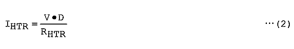
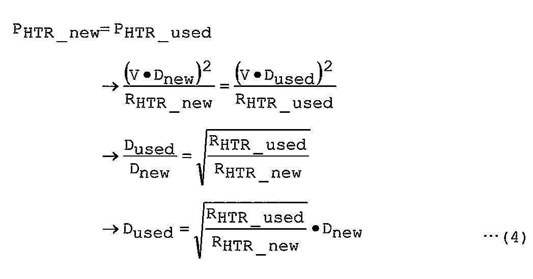
 第2の実施形態では、使用フェーズで実行されるフィードバック制御においてゲイン部12のゲインとリミッタ部14で用いられるリミッタ幅(範囲)とのうちの少なくとも一方を変更する制御を説明する。
(Second Embodiment)
In the second embodiment, control for changing at least one of the gain of the gain unit 12 and the limiter width (range) used by the limiter unit 14 in feedback control executed in the use phase will be described.
 エアロゾル発生物品9を加熱するエアロゾル生成装置1において、エアロゾル発生物品9から生成されるエアロゾルを継時的に安定させるためには、負荷3又はエアロゾル発生物品9の温度を徐々に上げることにより、エアロゾル発生物品9におけるエアロゾル生成位置を、負荷3の近くから徐々に遠くへ遷移させる必要がある。この理由は、負荷3からエアロゾル発生物品9への熱伝導を考えた場合、エアロゾル発生物品9に対する加熱を開始すると、エアロゾル発生物品9において負荷3に近い位置ほど早期にエアロゾルが生成されるためである。すなわち、エアロゾル発生物品9において負荷3から近い位置のエアロゾル源が霧化され尽くされてエアロゾル生成が完了した場合、継続してエアロゾル発生物品9からエアロゾルを生成するためには、負荷3から遠い位置のエアロゾル源を霧化する必要がある。つまり、エアロゾル発生物品9における負荷3から近い位置から、負荷3からの熱伝導効率が劣るためにエアロゾル源が霧化され尽くされていないエアロゾル発生物品9における負荷3から遠い位置へ、エアロゾル生成位置を遷移させる必要がある。 In the aerosol generating apparatus 1 for heating the aerosol generating article 9, in order to stabilize the aerosol generated from the aerosol generating article 9 over time, the aerosol is gradually increased by increasing the temperature of the load 3 or the aerosol generating article 9. It is necessary to gradually change the aerosol generation position in the generated article 9 from near the load 3 to far away. This is because when heat conduction from the load 3 to the aerosol generating article 9 is considered, when heating of the aerosol generating article 9 is started, the aerosol is generated earlier at a position closer to the load 3 in the aerosol generating article 9. is there. That is, in the aerosol generating article 9, when the aerosol generation at the position close to the load 3 is completely atomized and the aerosol generation is completed, in order to continuously generate the aerosol from the aerosol generating article 9, a position far from the load 3 is required. It is necessary to atomize the aerosol source. That is, the aerosol generation position from the position near the load 3 in the aerosol generating article 9 to the position far from the load 3 in the aerosol generating article 9 in which the aerosol source is not completely atomized due to poor heat conduction efficiency from the load 3. Must be transitioned.
 前述した通り、エアロゾル発生物品9において負荷3から遠い位置は、エアロゾル発生物品9において負荷3から近い位置に比べて、負荷3からの熱伝導の観点で劣る。従って、エアロゾル発生物品9において負荷3から遠い位置でエアロゾルを生成しようとすると、エアロゾル発生物品9において負荷3から近い位置でエアロゾルを生成させる場合と比べて負荷3は多くの熱をエアロゾル発生物品9に伝える必要がある。換言すれば、エアロゾル発生物品9において負荷3から遠い位置でエアロゾルを生成しようとすると、エアロゾル発生物品9において負荷3から近い位置でエアロゾルを生成させる場合と比べて負荷3の温度を高くする必要がある。 As described above, the position farther from the load 3 in the aerosol-generating article 9 is inferior in terms of heat conduction from the load 3 than the position closer to the load 3 in the aerosol-generating article 9. Therefore, when generating aerosol at a position far from the load 3 in the aerosol generating article 9, the load 3 generates more heat than the case where the aerosol is generated at a position near the load 3 in the aerosol generating article 9. Need to tell. In other words, if an aerosol is generated at a position far from the load 3 in the aerosol-generating article 9, it is necessary to increase the temperature of the load 3 as compared with a case where the aerosol is generated at a position near the load 3 in the aerosol-generating article 9. is there.
 第2の実施形態では、エアロゾル発生物品9におけるエアロゾル生成位置を負荷3から近い位置から遠い位置へ遷移させることで、エアロゾル発生物品9から生成されるエアロゾルの量を継時的に安定させるための制御を説明する。 In the second embodiment, the aerosol generation position in the aerosol generating article 9 is shifted from a position close to the load 3 to a position far from the load 3 to stabilize the amount of aerosol generated from the aerosol generating article 9 over time. The control will be described.
 例えば、負荷3がエアロゾル発生物品9を内部から加熱する第1の加熱方法が用いられる場合、エアロゾル発生物品9の中心部が、エアロゾル発生物品9において負荷3から近い位置となる。またエアロゾル発生物品9の外周部が、エアロゾル発生物品9において負荷3から遠い位置となる。 For example, when the first heating method in which the load 3 heats the aerosol-generating article 9 from the inside is used, the center of the aerosol-generating article 9 is located near the load 3 in the aerosol-generating article 9. Further, the outer peripheral portion of the aerosol generating article 9 is located far from the load 3 in the aerosol generating article 9.
 例えば、負荷3がエアロゾル発生物品9を外部から加熱する第2の加熱方法が用いられる場合、エアロゾル発生物品9の外周部が、エアロゾル発生物品9において負荷3から近い位置となる。またエアロゾル発生物品9の中心部が、エアロゾル発生物品9において負荷3から遠い位置となる。 For example, when the second heating method in which the load 3 heats the aerosol-generating article 9 from the outside is used, the outer peripheral portion of the aerosol-generating article 9 is positioned near the load 3 in the aerosol-generating article 9. Further, the center of the aerosol generating article 9 is located far from the load 3 in the aerosol generating article 9.
 例えば、負荷3が誘導加熱(IH)を用いてエアロゾル発生物品9を加熱する第3の加熱方法が用いられる場合、エアロゾル発生物品9においてサセプタと接する又は近い位置が、エアロゾル発生物品9において負荷3から近い位置となる。またエアロゾル発生物品9においてサセプタと接しない又は遠い位置が、エアロゾル発生物品9において負荷3から遠い位置となる。 For example, when the third heating method in which the load 3 heats the aerosol-generating article 9 using induction heating (IH) is used, the position of the aerosol-generating article 9 in contact with or close to the susceptor is the load 3 in the aerosol-generating article 9. It will be close to. Further, a position in the aerosol generating article 9 that is not in contact with or far from the susceptor is a position far from the load 3 in the aerosol generating article 9.
 しかしながら、フィードバック制御における目標温度を徐々に上げることにより負荷3又はエアロゾル発生物品9の温度を徐々に上げようとすると、温度測定値が目標温度を一時的に上回った場合にその際の温度上昇が停滞し、エアロゾルを吸引するユーザに違和感を与える場合がある。 However, if it is attempted to gradually increase the temperature of the load 3 or the aerosol generating article 9 by gradually increasing the target temperature in the feedback control, if the temperature measurement value temporarily exceeds the target temperature, the temperature rise at that time In some cases, the user is stagnant and feels uncomfortable for the user who inhales the aerosol.
 そこで、第2の実施形態においては、使用フェーズにおけるゲイン部12のゲインと、リミッタ部14のリミッタ幅との少なくとも一方を徐々に拡大し、負荷3又はエアロゾル発生物品9の温度を停滞なく滑らかに上昇させ、安定的にエアロゾルを生成する。なお、ゲイン部12のゲインの拡大とは、ゲインを拡大する前のゲイン部12に入力された入力値に対する出力値の絶対値より、ゲインを拡大した後のゲイン部12に入力された入力値に対する出力値の絶対値が大きくなるように、ゲイン部12における出力値と入力値の相関を調整することを意味するとしてもよい。また、リミッタ部14のリミッタ幅の拡大とは、リミッタ部14が出力する出力値の絶対値が取り得る最大値を大きくすることを意味するとしてもよい。 Therefore, in the second embodiment, at least one of the gain of the gain unit 12 and the limiter width of the limiter unit 14 in the use phase is gradually increased, and the temperature of the load 3 or the aerosol-generating article 9 is made smooth without stagnation. Raise and generate aerosol stably. The gain expansion of the gain unit 12 is an input value input to the gain unit 12 after the gain is expanded from the absolute value of the output value with respect to the input value input to the gain unit 12 before the gain is expanded. It may be meant that the correlation between the output value and the input value in the gain unit 12 is adjusted so that the absolute value of the output value with respect to is increased. Further, the expansion of the limiter width of the limiter unit 14 may mean increasing the maximum value that the absolute value of the output value output from the limiter unit 14 can take.
 第2の実施形態に係る制御部8による制御と既存のエアロゾル生成装置による制御とを対比すると、第2の実施形態に係る制御部8による制御は、フィードバック制御で用いられる目標温度を上げ、次に下げ、さらに次に上げるような制御ではなく、使用フェーズ終了温度を一定として制御を行う点で特徴的である。つまり、第2の実施形態においては、使用フェーズの大部分において、負荷3の温度はフィードバック制御で用いられる使用フェーズ終了温度よりも低いため、使用フェーズの全体に亘って負荷3又はエアロゾル発生物品9の温度を遅滞なく滑らかに上昇させ、安定的にエアロゾルを生成する。 When the control by the control unit 8 according to the second embodiment is compared with the control by the existing aerosol generation device, the control by the control unit 8 according to the second embodiment increases the target temperature used in the feedback control, and then The control is characterized in that the control is performed with the use phase end temperature constant, not the control that is lowered to the next and further increased. That is, in the second embodiment, in most of the use phase, the temperature of the load 3 is lower than the use phase end temperature used in the feedback control. Therefore, the load 3 or the aerosol generating article 9 is used throughout the use phase. The temperature is raised smoothly without delay, and aerosol is stably generated.
 第2の実施形態に係る制御部8による制御は、リミッタ部14のリミッタ幅をタイマ値tに基づき縮小するような制御ではない点で特徴的である。また、第2の実施形態に係る制御部8による制御は、リミッタ部14のリミッタ幅を一定として目標温度をタイマ値tに基づき上げるような制御ではない点で特徴的である。換言すれば、第2の実施形態に係る制御部8による制御において、リミッタ幅は、使用フェーズの進行に伴い縮小することなく、拡大し続けるか、又は、段階的に拡大する。 The control by the control unit 8 according to the second embodiment is characteristic in that it is not control that reduces the limiter width of the limiter unit 14 based on the timer value t. Further, the control by the control unit 8 according to the second embodiment is characteristic in that it is not a control in which the limiter width of the limiter unit 14 is constant and the target temperature is raised based on the timer value t. In other words, in the control by the control unit 8 according to the second embodiment, the limiter width continues to increase or gradually increases without decreasing as the use phase progresses.
 第2の実施形態に係る制御部8は、使用フェーズにおいて、例えば、負荷3の温度がエアロゾル発生物品9から既定量以上のエアロゾルを生成可能な値以上である場合に、負荷3の温度と使用フェーズの進行度とを取得し、負荷3の温度が既定温度に収束するようにフィードバック制御を実行し、フィードバック制御において、進行度が進むほど、フィードバック制御におけるゲイン、又は、電源4から負荷3へ供給される電力の上限値、を増加させてもよい。これにより、負荷3の温度を、徐々に、停滞なく、かつ、安定的に上げることができる。つまり使用フェーズ全体に亘って、エアロゾル発生物品9から生成されるエアロゾルの量を安定させることができる。 In the use phase, the control unit 8 according to the second embodiment, for example, when the temperature of the load 3 is equal to or higher than a value that can generate a predetermined amount or more of aerosol from the aerosol-generating article 9, is used. The degree of progress of the phase is acquired, and feedback control is executed so that the temperature of the load 3 converges to a predetermined temperature. In the feedback control, as the degree of progress progresses, the gain in the feedback control or the power supply 4 to the load 3 The upper limit value of the supplied power may be increased. As a result, the temperature of the load 3 can be increased gradually and stably without stagnation. That is, the amount of aerosol generated from the aerosol generating article 9 can be stabilized throughout the use phase.
 ここで、制御部8は、フィードバック制御におけるゲインの増加を、PID(Proportional Integral Differential)制御の比例(P)制御、積分(I)制御、微分(D)制御のいずれの要素の変更で行ってもよい。また制御部8は、比例制御、積分制御、微分制御のうち、1つのゲインを増加させてもよく、複数のゲインを増加させてもよい。また、制御部8は、ゲインの増加と負荷3へ供給される電力の上限値の増加の双方を行ってもよい。 Here, the control unit 8 increases the gain in the feedback control by changing any element of proportional (P) control, integral (I) control, and differential (D) control of PID (Proportional Integral Differential) control. Also good. Moreover, the control part 8 may increase one gain among proportional control, integral control, and differential control, and may increase a some gain. Further, the control unit 8 may both increase the gain and increase the upper limit value of the power supplied to the load 3.
 制御部8は、負荷3の温度が使用フェーズの開始時から減少しないように、進行度が進むほど、ゲイン又は上限値を増加させてもよい。これにより、エアロゾル生成量が低下することを抑制できる。 The control unit 8 may increase the gain or the upper limit value as the degree of progress advances so that the temperature of the load 3 does not decrease from the start of the use phase. Thereby, it can suppress that the aerosol production amount falls.
 進行度の進行幅に対するゲイン又は上限値の上昇幅は、一定としてもよい。これにより、フィードバック制御の安定性を向上させることができる。 The gain with respect to the progress width of the progress or the increase range of the upper limit value may be constant. Thereby, the stability of feedback control can be improved.
 制御部8は、進行度の進行幅に対するゲイン又は上限値の増加率を変化させてもよい。これにより、進行度に応じて適切な量のエアロゾルを生成できる。 The control unit 8 may change the gain or the increase rate of the upper limit value with respect to the progress width of the progress degree. Thereby, an appropriate amount of aerosol can be generated according to the degree of progress.
 制御部8は、進行度が進むほど、増加率を拡大させてもよい。これにより、エアロゾル生成量が低下することを抑制できる。また、負荷3が高温である時間を短くすることができ、負荷3及びエアロゾル生成装置1が過熱状態となることを抑制することができ、負荷3及びエアロゾル生成装置1の耐久性を向上させることができる。さらに、負荷3が高温である時間が短いため、エアロゾル生成装置1の断熱構造を簡略化できる。特にエアロゾル生成装置1が上記第2の加熱方法を採用する場合に、断熱構造の簡略化を図ることができる。 The control unit 8 may increase the increase rate as the degree of progress increases. Thereby, it can suppress that the aerosol production amount falls. Moreover, the time when the load 3 is high temperature can be shortened, the load 3 and the aerosol generating device 1 can be prevented from being overheated, and the durability of the load 3 and the aerosol generating device 1 can be improved. Can do. Furthermore, since the time when the load 3 is high temperature is short, the heat insulating structure of the aerosol generating apparatus 1 can be simplified. In particular, when the aerosol generating apparatus 1 employs the second heating method, the heat insulating structure can be simplified.
 制御部8は、進行度が進むほど、増加率を縮小させてもよい。これにより、負荷3が高温となる時間を長くすることができ、エアロゾル生成量が低下することを抑制できる。負荷3が高温となる時間を長くすることができるため、1つのエアロゾル発生物品9から生成されるエアロゾルの量を増加させることができる。また、ゲイン又は上限値が増加される期間が長いため、ユーザによるエアロゾルの吸引に伴う温度低下(例えば温度ドロップ)を迅速に回復し、負荷3の温度を補償することができる。つまり使用フェーズの全体に亘って、エアロゾル発生物品9から生成されるエアロゾルの量を安定させることができる。 The control unit 8 may reduce the increase rate as the progress degree progresses. Thereby, the time when the load 3 becomes high temperature can be lengthened, and it can suppress that the aerosol production amount falls. Since the time during which the load 3 becomes high temperature can be lengthened, the amount of aerosol generated from one aerosol generating article 9 can be increased. Further, since the period during which the gain or the upper limit value is increased is long, the temperature drop (for example, temperature drop) caused by the user's inhalation of the aerosol can be quickly recovered and the temperature of the load 3 can be compensated. That is, the amount of aerosol generated from the aerosol generating article 9 can be stabilized throughout the use phase.
 制御部8は、進行度が進むほどゲイン又は上限値が上昇する第1関係(相関)に基づき、進行度に対応するゲイン又は上限値を決定し、進行度の時系列的な変化に基づき第1関係を変更してもよい。これにより、進行度の進み具合に応じて、ゲイン又は上限値の拡張の度合いを変更することができ、実際の進み具合に応じて、負荷3へ適切な電力量を供給することができ、エアロゾル生成量を安定させることができる。 The control unit 8 determines the gain or upper limit value corresponding to the progress degree based on the first relationship (correlation) in which the gain or the upper limit value increases as the progress degree progresses. 1 relationship may be changed. Accordingly, the degree of expansion of the gain or the upper limit value can be changed according to the progress degree of the progress degree, and an appropriate amount of power can be supplied to the load 3 according to the actual progress degree. The amount produced can be stabilized.
 制御部8は、進行度が進むほどゲイン又は上限値が上昇するように第1関係を変更してもよい。この場合、ゲイン又は上限値が下がらないため、エアロゾル生成量が低下することを抑制できる。 The control unit 8 may change the first relationship so that the gain or the upper limit value increases as the degree of progress increases. In this case, since the gain or the upper limit value does not decrease, the aerosol generation amount can be suppressed from decreasing.
 制御部8は、進行度が既定の進行度より遅れている場合に、進行度の進行幅に対応するゲイン又は上限値の上昇幅が大きくなるように第1関係を変更し、進行度は、負荷3の温度としてもよい。これにより、負荷3の温度上昇が遅れているほど、負荷3の温度を上がりやすくすることができるため、エアロゾル生成量が低下することを抑制できる。 The control unit 8 changes the first relationship so that the gain corresponding to the progress width of the progress degree or the increase range of the upper limit value becomes larger when the progress degree is delayed from the predetermined progress degree. The temperature of the load 3 may be set. Thereby, since the temperature of the load 3 can be easily increased as the temperature increase of the load 3 is delayed, it is possible to suppress a decrease in the aerosol generation amount.
 制御部8は、進行度が既定の進行度より進んでいる場合に、進行度の進行幅に対応するゲイン又は上限値の上昇幅が小さくなるように第1関係を変更し、進行度は、負荷3の温度としてもよい。これにより、負荷3の温度上昇が進んでいるほど、負荷3の温度を上がりにくくすることができるため、エアロゾル生成量が大きくなることを抑制できる。 The control unit 8 changes the first relationship so that the gain corresponding to the progress width of the progress degree or the increase range of the upper limit value becomes smaller when the progress degree is ahead of the predetermined progress degree. The temperature of the load 3 may be set. Thereby, since the temperature of the load 3 can be made harder to increase as the temperature of the load 3 increases, it is possible to suppress an increase in the amount of aerosol generation.
 制御部8は、進行度が既定の進行度より遅れている場合に、進行度の進行幅に対応するゲイン又は上限値の上昇幅が小さくなるように第1関係を変更し、進行度は、エアロゾル吸引回数、エアロゾル吸引量、エアロゾル生成量のうちの少なくとも1つを含むとしてもよい。例えば、エアロゾルの吸引が既定の進行度より遅れている場合には、負荷3の近傍のエアロゾル源が枯渇していないことが考えられる。このような場合に、ゲイン又は上限値の上昇幅を小さくすることで、エアロゾル発生物品9内のエアロゾル源を有効に利用することができる。 The control unit 8 changes the first relationship so that the gain corresponding to the progress width of the progress degree or the increase range of the upper limit value becomes smaller when the progress degree is delayed from the predetermined progress degree. It may include at least one of the number of aerosol inhalations, the amount of aerosol inhalation, and the amount of aerosol generation. For example, when aerosol suction is delayed from a predetermined degree of progress, it is considered that the aerosol source in the vicinity of the load 3 is not exhausted. In such a case, the aerosol source in the aerosol generating article 9 can be used effectively by reducing the increase width of the gain or the upper limit value.
 制御部8は、進行度が既定の進行度より進んでいる場合に、進行度の進行幅に対応するゲイン又は上限値の上昇幅が大きくなるように第1関係を変更し、進行度は、エアロゾル吸引回数、エアロゾル吸引量、エアロゾル生成量のうちの少なくとも1つを含むとしてもよい。例えば、エアロゾルの吸引が既定の進行度より進んでいる場合には、エアロゾル発生物品9におけるエアロゾル生成位置が想定より負荷3から遠い位置へ遷移していることが考えられる。このような場合であっても、ゲイン又は上限値の上昇幅を大きくすることで、負荷3から遠いエアロゾル生成位置からエアロゾルを積極的に生成させることができる。 The control unit 8 changes the first relation so that the gain corresponding to the progress width of the progress degree or the increase range of the upper limit value becomes larger when the progress degree is ahead of the predetermined progress degree. It may include at least one of the number of aerosol inhalations, the amount of aerosol inhalation, and the amount of aerosol generation. For example, when the suction of the aerosol is advanced from a predetermined degree of progress, it is conceivable that the aerosol generation position in the aerosol generating article 9 has shifted to a position farther from the load 3 than expected. Even in such a case, it is possible to positively generate aerosol from the aerosol generation position far from the load 3 by increasing the increase range of the gain or the upper limit value.
 制御部8は、第1関係を一時的に変更、又は、第1関係の一部を変更してもよい。この場合、ゲイン又は上限値の上昇幅が一時的に変更され、その後、元の上昇幅に戻るため、制御の安定性を向上させることができる。 The control unit 8 may temporarily change the first relationship or change a part of the first relationship. In this case, the increase range of the gain or the upper limit value is temporarily changed and then returned to the original increase range, so that the stability of the control can be improved.
 制御部8は、第1関係のうち制御部8によって取得された最新の進行度以降の全体部分を変更してもよい。この場合、ゲイン又は上限値の上昇幅が全体的に変更されるため、再度の変更が必要となる可能性を少なくすることができる。 The control unit 8 may change the entire portion after the latest degree of progress acquired by the control unit 8 in the first relationship. In this case, since the increase range of the gain or the upper limit value is changed as a whole, the possibility that it is necessary to change again can be reduced.
 なお、制御部8は、最新の進行度より過去の進行度を含む第1関係全体を変更してもよい。 Note that the control unit 8 may change the entire first relationship including the past degree of progress from the latest degree of progress.
 制御部8は、第1関係のうち制御部8によって取得された最新の進行度以降を変更し、第1関係の変更前と変更後において使用フェーズの終点における進行度とゲイン又は上限値との関係を同じにしてもよい。この場合、使用フェーズの終点におけるゲイン又は上限値は変更されないため、負荷3に与えられる電力量が大きく変更されることを抑制でき、制御の安定性を向上させることができる。 The control unit 8 changes after the latest degree of progress acquired by the control unit 8 in the first relationship, and the degree of progress and gain or upper limit value at the end point of the use phase before and after the change of the first relationship. The relationship may be the same. In this case, since the gain or the upper limit value at the end point of the use phase is not changed, it is possible to suppress a large change in the amount of electric power given to the load 3 and improve the stability of control.
 既定温度は、装着されたエアロゾル発生物品9に含まれており負荷3から最も離れた位置のエアロゾル源又はエアロゾル基材9aから、エアロゾルを生成するために必要な負荷3の温度としてもよい。これにより、エアロゾル発生物品9から効果的にエアロゾルを生成させることができる。 The predetermined temperature may be the temperature of the load 3 necessary for generating the aerosol from the aerosol source or the aerosol base material 9a which is included in the mounted aerosol generating article 9 and is farthest from the load 3. Thereby, aerosol can be effectively generated from the aerosol generating article 9.
 制御部8は、負荷3の温度が既定温度に到達した場合に、使用フェーズを終了してもよい。これにより、エアロゾル発生物品9が過熱状態となることを抑制できる。 The control unit 8 may end the use phase when the temperature of the load 3 reaches a predetermined temperature. Thereby, it can suppress that the aerosol generating article 9 will be in an overheated state.
 制御部8は、負荷3の温度が既定温度に到達した場合、又は、進行度が既定閾値に到達した場合に、使用フェーズを終了してもよい。これにより、より安全かつ確実にフィードバック制御を終了させることができる。 The control unit 8 may end the use phase when the temperature of the load 3 reaches a predetermined temperature or when the degree of progress reaches a predetermined threshold. Thereby, feedback control can be terminated more safely and reliably.
 制御部8は、負荷3の温度が既定温度に到達し、且つ、進行度が既定閾値に到達した場合に、使用フェーズを終了してもよい。これにより、適切な範囲で終了条件を厳しくし、エアロゾル発生物品9からより多くのエアロゾルを生成させることができる。 The control unit 8 may end the use phase when the temperature of the load 3 reaches a predetermined temperature and the progress degree reaches a predetermined threshold. As a result, the termination conditions are tightened within an appropriate range, and more aerosol can be generated from the aerosol-generating article 9.
 制御部8は、使用フェーズにおいて、負荷3の温度が既定温度以上である時間より、負荷3の温度が既定温度未満である時間の方が長くなるように、ゲイン又は上限値を増加させてもよい。この場合、既定温度の近傍に負荷3の温度がない時間の方が、既定温度の近傍に負荷3の温度がある時間より長くなるため、エアロゾルの生成量が大きくなることを抑制できる。 In the use phase, the control unit 8 may increase the gain or the upper limit value so that the time during which the temperature of the load 3 is lower than the predetermined temperature is longer than the time during which the temperature of the load 3 is equal to or higher than the predetermined temperature. Good. In this case, since the time when the temperature of the load 3 is not near the predetermined temperature is longer than the time when the temperature of the load 3 is near the predetermined temperature, an increase in the amount of aerosol generated can be suppressed.
 進行度は、制御部8の制御に応じて、使用フェーズの経過時間、エアロゾル吸引回数、エアロゾル吸引量、エアロゾル生成量、又は、負荷3の温度を用いることができる。 As the degree of progress, the elapsed time of the use phase, the number of aerosol inhalations, the amount of aerosol inhalation, the amount of aerosol generation, or the temperature of the load 3 can be used according to the control of the control unit 8.
 第2の実施形態に係る制御部8は、例えば、負荷3の温度が、エアロゾル発生物品9に含まれており負荷3から最も近い位置のエアロゾル源又はエアロゾル基材9aから既定量以上のエアロゾルを生成可能な第1温度から、エアロゾル発生物品9に含まれており負荷3から最も遠い位置のエアロゾル源又はエアロゾル基材9aから既定量以上のエアロゾルを生成可能な第2温度へ、漸近するように、フィードバック制御におけるゲイン、又は、電源4から負荷3へ供給される電力の上限値、を増加させる。これにより、制御部8はフィードバック制御によって、エアロゾル発生物品9における負荷3から近い位置から遠い位置までの全体にわたってエアロゾル生成を効果的に行うことができる。 The control unit 8 according to the second embodiment, for example, generates an aerosol of a predetermined amount or more from an aerosol source or an aerosol base material 9a at a position closest to the load 3 where the temperature of the load 3 is included in the aerosol generating article 9. Ascending gradually from the first temperature that can be generated to the second temperature that is included in the aerosol generating article 9 and that can generate a predetermined amount or more of aerosol from the aerosol source or the aerosol base material 9a farthest from the load 3. The gain in the feedback control or the upper limit value of the power supplied from the power source 4 to the load 3 is increased. Thereby, the control part 8 can perform an aerosol production | generation effectively over the whole from the position close | similar to the position far from the load 3 in the aerosol generating article 9 by feedback control.
 第2の実施形態に係る制御部8は、例えば、負荷3の温度がエアロゾル発生物品9から既定量以上のエアロゾルを生成可能な値以上である使用フェーズの場合に、負荷3の温度と使用フェーズの進行度とを取得し、負荷3の温度と既定温度との差分に基づき電源4から負荷3へ供給される電力を決定し、且つ、使用フェーズの進行にそった電力の供給量の変化率が使用フェーズの進行にそった既定温度の変化率よりも大きくなるように、フィードバック制御を実行してもよい。なお、変化率は、ゼロ、すなわち、変化していない状態も含むとしてもよい。これにより、負荷3の温度を、徐々に、停滞なく、かつ、安定的に上げることができる。 The controller 8 according to the second embodiment, for example, when the temperature of the load 3 is a use phase where the temperature of the load 3 is not less than a value that can generate a predetermined amount or more of aerosol from the aerosol-generating article 9, the temperature of the load 3 and the use phase And the rate of change in the amount of power supplied along with the progress of the use phase is determined based on the difference between the temperature of the load 3 and the predetermined temperature. The feedback control may be executed so that becomes greater than the rate of change of the predetermined temperature along with the progress of the use phase. Note that the rate of change may be zero, that is, include a state in which no change has occurred. As a result, the temperature of the load 3 can be increased gradually and stably without stagnation.
 第2の実施形態に係る制御部8は、例えば、負荷3の温度がエアロゾル発生物品9から既定量以上のエアロゾルを生成可能な値以上である使用フェーズの場合に、負荷3の温度と使用フェーズの進行度とを取得し、負荷3の温度と既定温度との差分に基づき電源4から負荷3へ供給される電力を決定し、且つ、使用フェーズの進行にそって既定温度から負荷3の温度を引いた値が減少し、使用フェーズの進行にそって電源4から負荷3へ供給される電力の供給量が増加するように、フィードバック制御を実行してもよい。これにより、負荷3の温度を、徐々に、停滞なく、かつ、安定的に上げることができる。 The controller 8 according to the second embodiment, for example, when the temperature of the load 3 is a use phase where the temperature of the load 3 is not less than a value that can generate a predetermined amount or more of aerosol from the aerosol-generating article 9, , The power supplied from the power source 4 to the load 3 is determined based on the difference between the temperature of the load 3 and the predetermined temperature, and the temperature of the load 3 from the predetermined temperature as the use phase progresses Feedback control may be executed so that the value obtained by subtracting decreases and the supply amount of power supplied from the power source 4 to the load 3 increases as the use phase progresses. As a result, the temperature of the load 3 can be increased gradually and stably without stagnation.
 上記の制御部8による各種の制御は、制御部8がプログラムを実行することにより実現されてもよい。 The various controls by the control unit 8 may be realized by the control unit 8 executing a program.
 上記のような第2の実施形態について、さらに以下の実施例2A~2Fで具体的な制御例を説明する。 For the second embodiment as described above, further specific control examples will be described in the following Examples 2A to 2F.
  <実施例2A>
 図18は、実施例2Aに係る制御部8によって実行される制御の例を示す制御ブロック図である。
<Example 2A>
FIG. 18 is a control block diagram illustrating an example of control executed by the control unit 8 according to Example 2A.
 制御部8のリミッタ変更部13は、タイマ値tと負荷3の温度測定値とパフプロファイルとの少なくとも1つを含む入力パラメータとリミッタ部14のリミッタ幅とを関連付けた第1関係を保持する。タイマ値t、負荷3の温度測定値、パフプロファイルは、使用フェーズの進行度を表す値の例であり、これらに代えて使用フェーズの進行度に応じて増大する傾向を持つ他の物理量又は変数を用いてもよい。 The limiter changing unit 13 of the control unit 8 maintains a first relationship in which input parameters including at least one of the timer value t, the temperature measurement value of the load 3 and the puff profile are associated with the limiter width of the limiter unit 14. The timer value t, the temperature measurement value of the load 3, and the puff profile are examples of values indicating the progress of the use phase. Instead, other physical quantities or variables having a tendency to increase according to the progress of the use phase. May be used.
 実施例2Aにおいては、タイマ値tと温度測定値とパフプロファイルとを入力パラメータとして用いる場合を例として説明するが、タイマ値tと温度測定値とパフプロファイルとのうちの一部を入力パラメータとして用いてもよい。 In the embodiment 2A, a case where the timer value t, the temperature measurement value, and the puff profile are used as input parameters will be described as an example. It may be used.
 入力パラメータとリミッタ幅との関係付けは、テーブルで管理されてもよく、リスト構造などのデータ構造で管理されてもよく、入力パラメータとリミッタ幅とに関する関数が用いられてもよい。以下の各種の関係付けについても同様である。 The relationship between the input parameter and the limiter width may be managed by a table, may be managed by a data structure such as a list structure, or a function related to the input parameter and the limiter width may be used. The same applies to the following various relationships.
 制御部8は、使用フェーズにおいて、タイマ5からタイマ値tを入力し、温度測定部6から負荷3の温度を示す温度測定値を入力する。 The control unit 8 inputs the timer value t from the timer 5 and the temperature measurement value indicating the temperature of the load 3 from the temperature measurement unit 6 in the use phase.
 制御部8は、例えば、エアロゾル生成装置1が備える流量センサ、流速センサ、圧力センサなどのユーザの吸引に伴って変動する物理量を検出するセンサの出力値に基づきユーザの吸引を検知し、例えば時系列的なユーザの吸引回数又は吸引量などのような吸引状態を示すパフプロファイルを生成する。 For example, the control unit 8 detects the user's suction based on the output value of a sensor that detects a physical quantity that varies with the user's suction, such as a flow rate sensor, a flow rate sensor, and a pressure sensor included in the aerosol generation device 1. A puff profile indicating a suction state such as a sequential user's number of suctions or suction amount is generated.
 制御部8は、リミッタ変更部13、差分部11、ゲイン部12、リミッタ部14を含む。 The control unit 8 includes a limiter changing unit 13, a difference unit 11, a gain unit 12, and a limiter unit 14.
 リミッタ変更部13は、入力パラメータに基づきリミッタ部14で用いられるリミッタ幅の上昇幅を決定し、使用フェーズの進行が進むにつれて、リミッタ幅を徐々に拡大する。 The limiter changing unit 13 determines an increase width of the limiter width used in the limiter unit 14 based on the input parameter, and gradually increases the limiter width as the use phase progresses.
 実施例2Aにおいて、リミッタ変更部13は、例えば、リミッタ幅を狭くすることはないとしてもよい。換言すれば、リミッタ変更部13は、リミッタ幅を変更する際には、その拡大のみを行ってもよい。以下、第2の実施形態の実施例2B~2Fにおいても同様に、リミッタ変更部13で用いられるリミッタ幅が狭くなることはないとしてもよい。 In Example 2A, the limiter changing unit 13 may not reduce the limiter width, for example. In other words, the limiter changing unit 13 may perform only enlargement when changing the limiter width. Similarly, in Examples 2B to 2F of the second embodiment, similarly, the limiter width used in the limiter changing unit 13 may not be narrowed.
 より具体的には、リミッタ変更部13は、タイマ値tの増加に応じて、リミッタ最大値とリミッタ最小値との間の幅が拡大するようにリミッタ部14のリミッタ幅を変更する。 More specifically, the limiter changing unit 13 changes the limiter width of the limiter unit 14 so that the width between the maximum limiter value and the minimum limiter value is increased as the timer value t increases.
 差分部11は、温度測定部6によって測定された温度測定値と使用フェーズ終了温度との差を求める。実施例2Aにおいて、使用フェーズ終了温度は、固定値であり、フィードバック制御により例えば使用フェーズの終了時に負荷3の温度が到達すべき値であるとする。 The difference unit 11 obtains a difference between the temperature measurement value measured by the temperature measurement unit 6 and the use phase end temperature. In Example 2A, the use phase end temperature is a fixed value, and is assumed to be a value that the temperature of the load 3 should reach at the end of the use phase by feedback control, for example.
 ゲイン部12は、温度測定値と使用フェーズ終了温度の差に基づき当該差をなくす、又は、小さくするようなデューティ比を求める。換言すれば、ゲイン部12は、温度測定値と使用フェーズ終了温度の差とデューティ比との相関を持ち、入力された温度測定値と使用フェーズ終了温度との差に対応するデューティ比をリミッタ部14に対して出力する。 The gain unit 12 obtains a duty ratio that eliminates or reduces the difference based on the difference between the temperature measurement value and the use phase end temperature. In other words, the gain unit 12 has a correlation between the difference between the temperature measurement value and the use phase end temperature and the duty ratio, and the duty unit corresponding to the difference between the input temperature measurement value and the use phase end temperature is a limiter unit. 14 is output.
 リミッタ部14は、ゲイン部12によって求められたデューティ比がリミッタ幅に含まれるように制御する。具体的には、リミッタ部14は、ゲイン部12によって求められたデューティ比がリミッタ変更部13で求められたリミッタ幅の最大値を超える場合に、デューティ比をリミッタ幅の最大値とし、求められたデューティ比がリミッタ変更部13で求められたリミッタ幅の最小値を下回る場合に、デューティ比をリミッタ幅の最小値に制限する。リミッタ部14は、リミッタ処理の結果として、リミッタ幅に含まれるデューティ比を示すデューティ操作値を、例えば図3で示された比較部15へ出力する。デューティ操作値は、制御部8のフィードバック制御の結果得られた値であるとする。 The limiter unit 14 performs control so that the duty ratio obtained by the gain unit 12 is included in the limiter width. Specifically, the limiter unit 14 obtains the duty ratio as the maximum value of the limiter width when the duty ratio obtained by the gain unit 12 exceeds the maximum value of the limiter width obtained by the limiter changing unit 13. When the duty ratio falls below the minimum value of the limiter width obtained by the limiter changing unit 13, the duty ratio is limited to the minimum value of the limiter width. As a result of the limiter process, the limiter unit 14 outputs a duty operation value indicating the duty ratio included in the limiter width, for example, to the comparison unit 15 shown in FIG. It is assumed that the duty operation value is a value obtained as a result of the feedback control of the control unit 8.
 図19は、実施例2Aに係る制御部8による使用フェーズの処理の例を示すフローチャートである。 FIG. 19 is a flowchart illustrating an example of usage phase processing by the control unit 8 according to the embodiment 2A.
 ステップS1901において、制御部8は、タイマ5からタイマ値tを入力する。 In step S1901, the control unit 8 inputs a timer value t from the timer 5.
 ステップS1902において、制御部8は、タイマ値tが使用フェーズ終了を示す時間tthre以上か否か判断する。 In step S1902, the control unit 8 determines whether or not the timer value t is equal to or greater than the time t thre indicating the end of the use phase.
 タイマ値tが時間tthre以上の場合(ステップS1902における判断が肯定的である場合)、制御部8は、負荷3への電力供給を停止し、使用フェーズを終了する。 When the timer value t is equal to or greater than the time t thre (when the determination in step S1902 is affirmative), the control unit 8 stops the power supply to the load 3 and ends the use phase.
 タイマ値tが時間tthre以上ではない場合(ステップS1902における判断が否定的である場合)、ステップS1903において、制御部8の差分部11は、負荷3の使用フェーズ終了温度と温度測定部6から入力した温度測定値との差分ΔTHTRを求める。 When the timer value t is not equal to or greater than the time t thre (when the determination in step S1902 is negative), in step S1903, the difference unit 11 of the control unit 8 determines from the use phase end temperature of the load 3 and the temperature measurement unit 6 The difference ΔT HTR from the input temperature measurement value is obtained.
 ステップS1904において、制御部8のリミッタ変更部13は、タイマ値t、温度測定値、パフプロファイルのうち少なくとも1つに基づき、リミッタ部14で用いられるリミッタ幅の上昇幅を決定し、リミッタ幅を変更する。 In step S1904, the limiter changing unit 13 of the control unit 8 determines an increase width of the limiter width used in the limiter unit 14 based on at least one of the timer value t, the temperature measurement value, and the puff profile, and sets the limiter width. change.
 ステップS1905において、制御部8のゲイン部12は、差分ΔTHTRに基づきデューティ比(デューティ操作値)Dcmdを求める。ゲイン部12における入力値と出力値の相関を関数Kとすると、このゲイン部12の処理は、Dcmd=K(ΔTHTR)と表すことができる。特に、ゲイン部12における入力値と出力値の相関が線形であるならば、当該相関の傾きであるゲイン係数をKとすると、このゲイン部12の処理は、Dcmd=K×ΔTHTRと表すこともできる。 In step S1905, the gain section 12 of the control unit 8, the duty ratio based on the difference [Delta] T HTR (duty operation value) obtaining the D cmd. When the correlation between the input value and the output value in the gain unit 12 is a function K, the processing of the gain unit 12 can be expressed as D cmd = K (ΔT HTR ). In particular, if the correlation between the input value and the output value in the gain unit 12 is linear, the processing of the gain unit 12 is expressed as D cmd = K × ΔT HTR , where K is the gain coefficient that is the slope of the correlation. You can also
 ステップS1906において、制御部8のリミッタ部14は、ゲイン部12によって求められたデューティ比Dcmdがリミッタ部14のリミッタ幅に収まるようにリミッタ処理を行い、リミッタ処理されたデューティ比Dcmddを求める。 In step S1906, the limiter portion 14 of the control unit 8, the duty ratio D cmd determined by the gain unit 12 performs a limiter process to fit the limiter width of the limiter unit 14, obtains the limiter process duty ratio D CMDD .
 ステップS1907において、制御部8は、デューティ比Dcmddを示すデューティ指令値に基づき負荷3へ供給される電力を制御し、その後処理はステップS1901へ戻る。なお、デューティ比Dcmddは、電源4と負荷3の間に設けられた開閉器25に適用されてもよく、電源4と負荷3の間に設けられたDC/DCコンバータに適用されてもよい。 In step S1907, the control unit 8 controls the power supplied to the load 3 based on the duty command value indicating the duty ratio D cmdd , and the process returns to step S1901. The duty ratio D cmdd may be applied to the switch 25 provided between the power source 4 and the load 3 or may be applied to a DC / DC converter provided between the power source 4 and the load 3. .
 なお、上記の処理において、ステップS1904とステップS1905とは、順序を入れ替えてもよい。 In the above processing, step S1904 and step S1905 may be switched in order.
 以上説明した実施例2Aに係る制御部8が実行する制御においては、使用フェーズが進行するごとにリミッタ部14で用いられるリミッタ幅が徐々に拡大されるように変更され、リミッタ幅内のデューティ比Dcmddに基づき負荷3の温度が制御される。これにより、負荷3又はエアロゾル発生物品9の温度を停滞なく滑らかに上昇させることができ、安定的にエアロゾルを生成することができる。 In the control executed by the control unit 8 according to the embodiment 2A described above, the limiter width used in the limiter unit 14 is changed so as to gradually increase each time the use phase proceeds, and the duty ratio within the limiter width is changed. The temperature of the load 3 is controlled based on D cmdd . Thereby, the temperature of the load 3 or the aerosol generating article 9 can be raised smoothly without stagnation, and the aerosol can be generated stably.
  <実施例2B>
 実施例2Bでは、使用フェーズの時系列な進捗においてエアロゾル発生物品9の熱容量が想定よりも大きいか否かの判断に基づいて、リミッタ変更部13が、リミッタ幅の上昇幅を決定し、当該リミッタ幅を変更する制御を説明する。
<Example 2B>
In Example 2B, the limiter changing unit 13 determines the increase width of the limiter width based on the determination as to whether or not the heat capacity of the aerosol-generating article 9 is larger than expected in the chronological progress of the use phase. Control for changing the width will be described.
 実施例2Bにおいて、エアロゾル発生物品9の熱容量は、エアロゾル発生物品9の質量と比熱から厳密に求めてもよい。また別の一例として、エアロゾル発生物品9の熱容量は、エアロゾル発生物品9が備えるエアロゾル基材9a、香味源、エアロゾル源の組成又は構造に依存し、特にエアロゾル発生物品9、香味源、エアロゾル源の残量が多いほど高い値を示す物理量として扱ってもよい。つまり、負荷3によってエアロゾル発生物品9を加熱すると、エアロゾル基材9aと香味源又はエアロゾル源の少なくとも一部が消費されることにより、エアロゾル発生物品9の熱容量は、使用フェーズの進行に伴い減少する傾向を持つ。換言すれば、エアロゾル発生物品9の熱容量は、エアロゾル発生物品9が生成可能なエアロゾル量、エアロゾル生成装置1のユーザが吸引可能なエアロゾルの残量、吸引の残り回数、又は、エアロゾル生成装置1によるエアロゾル発生物品9への加熱可能量を表すとする。なお、エアロゾル発生物品9が生成可能なエアロゾル量、エアロゾル生成装置1のユーザが吸引可能なエアロゾル源の残量、又は、吸引の残り回数がゼロになった場合でも、エアロゾル発生物品9の熱容量はゼロにならない点に留意されたい。 In Example 2B, the heat capacity of the aerosol generating article 9 may be determined strictly from the mass and specific heat of the aerosol generating article 9. As another example, the heat capacity of the aerosol generating article 9 depends on the composition or structure of the aerosol base material 9a, the flavor source, and the aerosol source provided in the aerosol generating article 9, and in particular, the aerosol generating article 9, the flavor source, and the aerosol source. You may treat as a physical quantity which shows a high value, so that there are many remaining amounts. That is, when the aerosol generating article 9 is heated by the load 3, the aerosol base material 9a and at least a part of the flavor source or the aerosol source are consumed, so that the heat capacity of the aerosol generating article 9 decreases as the use phase progresses. Have a tendency. In other words, the heat capacity of the aerosol generating article 9 depends on the amount of aerosol that can be generated by the aerosol generating article 9, the remaining amount of aerosol that can be inhaled by the user of the aerosol generating apparatus 1, the remaining number of inhalations, or the aerosol generating apparatus 1. It is assumed that the amount capable of heating the aerosol generating article 9 is represented. The amount of aerosol that can be generated by the aerosol generating article 9, the remaining amount of the aerosol source that can be inhaled by the user of the aerosol generating apparatus 1, or the heat capacity of the aerosol generating article 9 is zero even when the remaining number of suctions becomes zero. Note that it is not zero.
 実施例2Bに係る制御部8及び/又はリミッタ変更部13は、使用フェーズの時系列的な進捗においてエアロゾル発生物品9の熱容量が想定よりも大きいか否かを、温度測定値又はパププロファイルに基づき判断してもよい。一例として、実施例2Bに係る制御部8及び/又はリミッタ変更部13は、使用フェーズにおける負荷3又はエアロゾル発生物品9の温度、使用フェーズにおけるエアロゾル生成装置1のユーザの吸引回数又は吸引量の積算値についての、理想的な時系列データを予め記憶しておく。そして、これら理想的な時系列データと温度測定値又はパフプロファイルとを比較することにより、使用フェーズの時系列的な進捗においてエアロゾル発生物品9の熱容量が想定より大きいか否かを判断してもよい。 The control unit 8 and / or the limiter changing unit 13 according to Example 2B determines whether the heat capacity of the aerosol-generating article 9 is larger than expected in the time-series progress of the use phase based on the temperature measurement value or the profile. You may judge. As an example, the control unit 8 and / or the limiter changing unit 13 according to Example 2B may integrate the temperature of the load 3 or the aerosol generating article 9 in the use phase, the number of suctions or the amount of suction of the user of the aerosol generating device 1 in the use phase. Ideal time-series data regarding values is stored in advance. Then, by comparing these ideal time-series data with the temperature measurement value or the puff profile, it is determined whether the heat capacity of the aerosol-generating article 9 is larger than expected in the time-series progress of the use phase. Good.
 具体的には、制御部8及び/又はリミッタ変更部13は、理想的な時系列データに対して温度測定値が遅延している場合は、エアロゾル発生物品9の熱容量が想定より大きいと判断してもよい。一方、制御部8及び/又はリミッタ変更部13は、理想的な時系列データに対して温度測定値が進行している場合は、エアロゾル発生物品9の熱容量が想定より小さいと判断してもよい。 Specifically, the control unit 8 and / or the limiter changing unit 13 determines that the heat capacity of the aerosol-generating article 9 is larger than expected when the temperature measurement value is delayed with respect to the ideal time-series data. May be. On the other hand, the control unit 8 and / or the limiter changing unit 13 may determine that the heat capacity of the aerosol-generating article 9 is smaller than expected when the temperature measurement value is progressing with respect to ideal time-series data. .
 換言すれば、エアロゾル発生物品9の熱容量が大きい状態では、温度測定値は低いと推定される。これとは逆に、エアロゾル発生物品9の熱容量が大きくない(小さい)状態では、温度測定値が高いと推定される。 In other words, when the heat capacity of the aerosol generating article 9 is large, the temperature measurement value is estimated to be low. On the contrary, when the heat capacity of the aerosol generating article 9 is not large (small), the temperature measurement value is estimated to be high.
 リミッタ変更部13は、温度測定値が低いことを示す場合に、リミッタ幅の上昇幅を拡大する。 The limiter changing unit 13 increases the increase width of the limiter width when indicating that the temperature measurement value is low.
 リミッタ変更部13は、温度測定値が高いことを示す場合に、リミッタ幅の上昇幅を縮小する。 The limiter changing unit 13 reduces the increase width of the limiter width when the measured temperature value is high.
 一方、制御部8及び/リミッタ変更部13は、理想的な時系列データに対してパフプロファイルが遅延している場合は、エアロゾル発生物品9の熱容量が想定より大きいと判断してもよい。このような場合においては、パフプロファイルが遅延していることから明らかなように、エアロゾル生成装置1に対するユーザの吸引が想定よりも行われていない。従って、リミッタ幅の上昇幅を拡大してエアロゾル発生物品9から生成されるエアロゾルの量を増加又は維持するようにリミッタ幅の上昇幅を拡大する必要が乏しい点に留意されたい。 On the other hand, when the puff profile is delayed with respect to the ideal time series data, the control unit 8 and / or the limiter changing unit 13 may determine that the heat capacity of the aerosol generating article 9 is larger than expected. In such a case, as is apparent from the fact that the puff profile is delayed, the user's suction to the aerosol generating device 1 is not performed as expected. Therefore, it should be noted that it is not necessary to increase the increase width of the limiter width so as to increase or maintain the amount of aerosol generated from the aerosol generating article 9 by increasing the increase width of the limiter width.
 また、制御部8及び/リミッタ変更部13は、理想的な時系列データに対してパフプロファイルが進行している場合は、エアロゾル発生物品9の熱容量が想定より小さいと判断してもよい。このような場合においては、パフプロファイルが進行していることから明らかなように、エアロゾル生成装置1に対するユーザの吸引が想定よりも行われている。従って、リミッタ幅の上昇幅を拡大してエアロゾル発生物品9から生成されるエアロゾルの量を増加又は維持するようにリミッタ幅の上昇幅を積極的に拡大する必要がある点に留意されたい。 Further, the control unit 8 and / or the limiter changing unit 13 may determine that the heat capacity of the aerosol-generating article 9 is smaller than expected when the puff profile is progressing with respect to ideal time-series data. In such a case, as is apparent from the progress of the puff profile, the user's suction with respect to the aerosol generating device 1 is performed more than expected. Therefore, it should be noted that it is necessary to positively increase the increase width of the limiter so as to increase or maintain the amount of aerosol generated from the aerosol generating article 9 by increasing the increase width of the limiter width.
 リミッタ変更部13は、パフプロファイルが遅延している場合に、リミッタ幅の上昇幅を縮小する。 The limiter changing unit 13 reduces the increase width of the limiter width when the puff profile is delayed.
 リミッタ変更部13は、パフプロファイルが進行している場合に、リミッタ幅の上昇幅を拡大する。 The limiter changing unit 13 increases the increase width of the limiter width when the puff profile is in progress.
 ただし、先で説明したように、使用フェーズの進行度に温度測定値とパフプロファイルとのどちらを用いる場合でも、実施例2Bでは、リミッタ変更部13は、使用フェーズの進行に伴いリミッタ幅を縮小することはないとする。 However, as described above, regardless of whether the measured temperature value or the puff profile is used for the progress of the use phase, in Example 2B, the limiter changing unit 13 reduces the limiter width as the use phase progresses. Suppose you don't.
 図20は、実施例2Bに係るリミッタ変更部13におけるリミッタ幅の変更例を示す図である。なお、図20における右上がりの破線は、変更前のリミッタ幅の上昇幅を示す。 図20における点線で示されるリミッタ幅の第1の変更例において、リミッタ変更部13は、入力パラメータに基づき、一時的に、リミッタ幅の上昇幅を拡大又は縮小し、その後、リミッタ幅の上昇幅を図20における右上がりの破線で示される変更前の状態に戻す。なお、リミッタ幅の第1の変更例において点線で示されるリミッタ幅が適用される領域では、リミッタ変更部13は、破線で示される変更前のリミッタ幅の上昇幅を出力しない点に留意されたい。 FIG. 20 is a diagram illustrating an example of changing the limiter width in the limiter changing unit 13 according to Example 2B. Note that a broken line rising to the right in FIG. 20 indicates an increase width of the limiter width before the change. In the first modification example of the limiter width indicated by the dotted line in FIG. 20, the limiter changing unit 13 temporarily increases or decreases the increase width of the limiter width based on the input parameter, and then increases the increase width of the limiter width. Is returned to the state before the change indicated by the broken line rising to the right in FIG. It should be noted that the limiter changing unit 13 does not output the increase width of the limiter width before the change indicated by the broken line in the region where the limiter width indicated by the dotted line is applied in the first change example of the limiter width. .
 図20における実線で示されるリミッタ幅の第2の変更例において、リミッタ変更部13は、入力パラメータに基づき、リミッタ幅の上昇幅を拡大又は縮小し、その後、その上昇幅によるリミッタ幅の変更を維持する。換言すれば、この第2の変更例においては、リミッタ幅と入力パラメータとを含む関数の切片が一律に変更される。 In the second modification example of the limiter width indicated by the solid line in FIG. 20, the limiter changing unit 13 expands or reduces the increase width of the limiter width based on the input parameter, and then changes the limiter width based on the increase width. maintain. In other words, in the second modification example, the intercept of the function including the limiter width and the input parameter is uniformly changed.
 図20における一点鎖線で示されるリミッタ幅の第3の変更例において、リミッタ変更部13は、入力パラメータに基づき、リミッタ幅の上昇幅を拡大又は縮小し、その後、使用フェーズの終了時に想定されていたリミッタ幅となるように、リミッタ幅の上昇幅を変更する。 In the third modification example of the limiter width indicated by the alternate long and short dash line in FIG. 20, the limiter changing unit 13 expands or reduces the increase width of the limiter width based on the input parameter, and then is assumed at the end of the use phase. The increase width of the limiter width is changed so that the limiter width becomes the same.
 図21は、実施例2Bに係る制御部8による使用フェーズの処理の例を示すフローチャートである。この図21では、パフプロファイル又は温度測定値に基づきリミッタ幅の上昇幅が決定され、決定された上昇幅に基づきリミッタ幅が変更される場合を例として説明している。 FIG. 21 is a flowchart illustrating an example of usage phase processing by the control unit 8 according to the second embodiment. FIG. 21 illustrates an example in which the increase width of the limiter width is determined based on the puff profile or the temperature measurement value, and the limiter width is changed based on the determined increase width.
 ステップS2101及びステップS2102は、上記図19のステップS1901及びステップS1902と同様である。 Step S2101 and Step S2102 are the same as Step S1901 and Step S1902 in FIG.
 ステップS2102においてタイマ値tが時間tthre以上ではないと判断された場合(判断が否定的な場合)、ステップS2103において、リミッタ変更部13へ、例えば、パフプロファイル又は温度測定値が入力される。 If it is determined in step S2102 that the timer value t is not equal to or greater than the time t thre (when the determination is negative), for example, a puff profile or a temperature measurement value is input to the limiter changing unit 13 in step S2103.
 ステップS2104において、リミッタ変更部13は、入力したパフプロファイル又は温度測定値が想定内(既定範囲内)か否か判断する。なお、入力したパフプロファイル又は温度測定値が想定内であるとは、前述した理想的な時系列データと、入力したパフプロファイル又は温度測定値との間の乖離が無い又は僅かであることを指す。 In step S2104, the limiter changing unit 13 determines whether or not the input puff profile or the temperature measurement value is within an assumption (within a predetermined range). Note that the input puff profile or temperature measurement value is within the range means that there is no or little difference between the ideal time series data described above and the input puff profile or temperature measurement value. .
 パフプロファイル又は温度測定値が想定内の場合(ステップS2104の判断が肯定的である場合)、処理はステップS2106に移動する。 If the puff profile or the temperature measurement value is within the expected range (if the determination in step S2104 is affirmative), the process moves to step S2106.
 パフプロファイル又は温度測定値が想定内ではない場合(ステップS2104の判断が否定的である場合)、ステップS2105において、リミッタ変更部13は、リミッタ幅の上昇幅を変更し、処理はステップS2106に移動する。 If the puff profile or the temperature measurement value is not within the expected range (if the determination in step S2104 is negative), in step S2105, the limiter changing unit 13 changes the increase width of the limiter width, and the process moves to step S2106. To do.
 ステップS2106からステップS2110は、上記図19のステップS1903からステップS1907と同様である。 Steps S2106 to S2110 are the same as steps S1903 to S1907 in FIG.
 以上説明した実施例2Bの作用効果について説明する。 The function and effect of Example 2B described above will be described.
 ユーザによってエアロゾル生成装置1によるエアロゾルの吸引ペースは異なり、また、エアロゾル生成装置1及び/又はエアロゾル発生物品9の間で不可避の製品誤差も存在する。実施例2Bにおいては、このようなユーザのエアロゾルの吸引ペースに基づく誤差及び製品誤差を解消・吸収するために、使用フェーズの進行度に基づきリミッタ部14で用いられるリミッタ幅の上昇幅を変更する。これにより、エアロゾル生成に関する制御を安定させることができる。 The aerosol inhalation pace by the aerosol generation device 1 varies depending on the user, and there is also an inevitable product error between the aerosol generation device 1 and / or the aerosol generating article 9. In Example 2B, in order to eliminate and absorb such errors and product errors based on the user's aerosol inhalation pace, the increase width of the limiter width used in the limiter unit 14 is changed based on the progress of the use phase. . Thereby, the control regarding aerosol production can be stabilized.
  <実施例2C>
 例えば、負荷3が高温となる時間を抑制することにより、エアロゾル発生物品9が過熱状態となることを抑制することができる。
<Example 2C>
For example, the aerosol generating article 9 can be prevented from being overheated by suppressing the time during which the load 3 is at a high temperature.
 他方で、負荷3が高温となる時間を長くすることにより、エアロゾル発生物品9のうち負荷3から離れた位置に対してエアロゾルの生成を促進させることができる。 On the other hand, by increasing the time during which the load 3 is at a high temperature, the generation of aerosol can be promoted to a position away from the load 3 in the aerosol generating article 9.
 そこで、実施例2Cでは、エアロゾル発生物品9の過熱を抑制するため、又は、エアロゾルの生成を促進させるために、リミッタ幅の上昇幅を拡大又は縮小し、負荷3の温度を制御することを説明する。 Therefore, in Example 2C, it is explained that the temperature of the load 3 is controlled by increasing or reducing the increase width of the limiter width in order to suppress overheating of the aerosol generating article 9 or to promote the generation of aerosol. To do.
 使用フェーズの全体に亘って安定してエアロゾルを生成するためには、エアロゾルの生成開始から時間が経てば、エアロゾル発生物品9のうち負荷3から離れた位置からエアロゾルを生成させる必要がある。 In order to stably generate aerosol throughout the use phase, it is necessary to generate aerosol from a position away from the load 3 in the aerosol-generating article 9 over time after the start of generation of aerosol.
 前述した通り、エアロゾル発生物品9のうち負荷3から離れた位置をエアロゾル生成に適用な温度とすると、負荷3はエアロゾルの生成開始時よりも高温とならなければならない。 As described above, assuming that the position away from the load 3 in the aerosol generating article 9 is a temperature applicable to aerosol generation, the load 3 must be higher than the start of aerosol generation.
 制御部8は、使用フェーズ終了時に負荷3が使用フェーズ終了温度となるように制御を行うが、使用フェーズ終了温度で維持される時間が短いほど、負荷3が過熱状態となることを抑制することができる。 The control unit 8 performs control so that the load 3 reaches the use phase end temperature at the end of the use phase, but suppresses the load 3 from being overheated as the time maintained at the use phase end temperature is shorter. Can do.
 その一方で、負荷3から離れた位置においても充分な量のエアロゾルを生成するために、負荷3が高温となる時間が長い方が好ましい場合もある。 On the other hand, in order to generate a sufficient amount of aerosol even at a position away from the load 3, it may be preferable that the time during which the load 3 becomes high temperature is long.
 図22は、リミッタ部14で用いられるリミッタ幅の変化と負荷3の温度上昇状態の例を示すグラフである。図22において、横軸は、タイマ値tを示す。縦軸は、温度又はリミッタ幅を示す。 FIG. 22 is a graph showing an example of the change in the limiter width used in the limiter unit 14 and the temperature rise state of the load 3. In FIG. 22, the horizontal axis represents the timer value t. The vertical axis indicates temperature or limiter width.
 線L28Aは、タイマ値(時間)tが小さいほどリミッタ幅の上昇幅が小さく、タイマ値tが大きいほどリミッタ幅の上昇幅が大きいことを示す。この線L28Aに対応する温度の変化が線L28Bである。この線L28Bは、負荷3の温度上昇が遅く、負荷3の温度が使用フェーズの終了に近づくにつれて大きくなる。リミッタ変更部13は、この線L28A及び線L28Bに従うようにリミッタ幅の上昇幅を変更することで、負荷3の過熱状態を防止することができる。 A line L 28A indicates that the increase amount of the limiter width is small as the timer value (time) t is small, and the increase amount of the limiter width is large as the timer value t is large. The change in temperature corresponding to the line L 28A is the line L 28B . This line L 28B has a slow temperature rise of the load 3 and becomes larger as the temperature of the load 3 approaches the end of the use phase. The limiter changing unit 13 can prevent an overheated state of the load 3 by changing the increase width of the limiter width so as to follow the line L 28A and the line L 28B .
 他方で、線L28Cは、タイマ値(時間)tが小さいほどリミッタ幅の上昇幅が大きく、タイマ値tが大きいほどリミッタ幅の上昇幅が小さくなることを示す。この線L28Cに対応する温度の変化が線L28Dである。この線L28Dは、負荷3の温度上昇が速く、負荷3の温度が使用フェーズ終了温度あたりで維持される時間が長くなる。リミッタ変更部13は、この線L28C及び線L28Dに従うようにリミッタ幅の上昇幅を変更することで、エアロゾル発生物品9における負荷3から遠い位置から充分にエアロゾルを生成することができる。 On the other hand, the line L 28C indicates that the increase width of the limiter width increases as the timer value (time) t decreases, and the increase width of the limiter width decreases as the timer value t increases. The change in temperature corresponding to this line L 28C is the line L 28D . In this line L 28D , the temperature of the load 3 rises quickly, and the time during which the temperature of the load 3 is maintained around the use phase end temperature becomes long. The limiter changing unit 13 can sufficiently generate an aerosol from a position far from the load 3 in the aerosol generating article 9 by changing the increase width of the limiter width so as to follow the line L 28C and the line L 28D .
 図23は、実施例2Cに係るリミッタ幅の変化の例を示すグラフである。 FIG. 23 is a graph showing an example of a change in the limiter width according to Example 2C.
 リミッタ変更部13は、例えば、原則としてタイマ値tに基づきリミッタ幅を変更し、さらに、パフプロファイルと温度測定値との少なくとも一方に基づきリミッタ幅を変更する際のリミッタ幅の上昇幅を決定する。 For example, the limiter changing unit 13 changes the limiter width based on the timer value t in principle, and further determines the increase width of the limiter width when changing the limiter width based on at least one of the puff profile and the temperature measurement value. .
 線L29Aは、リミッタ幅の上昇幅が拡大した状態を示し、線L29Bは、リミッタ幅の上昇幅が縮小した状態を示す。 Line L 29A shows a state in which the increase width of the limiter width is increased, and line L 29B shows a state in which the increase width of the limiter width is reduced.
 以上説明した実施例2Cにおいては、進行度に応じてリミッタ幅の上昇幅を変更して負荷3の過熱を抑制することができる。 In Example 2C described above, overheating of the load 3 can be suppressed by changing the increase width of the limiter width according to the degree of progress.
 また、実施例2Cにおいては、エアロゾル発生物品9における負荷3から離れた位置でエアロゾルを効果的に生成させることができる。 Further, in Example 2C, aerosol can be effectively generated at a position away from the load 3 in the aerosol generating article 9.
  <実施例2D>
 上記の実施例2A乃至実施例2Cは、リミッタ変更部13がリミッタ部14で用いられるリミッタ幅を変更することを説明している。
<Example 2D>
Embodiment 2A to Embodiment 2C described above describe that the limiter changing unit 13 changes the limiter width used in the limiter unit 14.
 これに対して、実施例2Dでは、タイマ値t、負荷3の温度、パフプロファイルの少なくとも1つを含む入力パラメータに基づきゲイン部12のゲインを変更することを説明する。 In contrast, in Example 2D, it will be described that the gain of the gain unit 12 is changed based on input parameters including at least one of the timer value t, the temperature of the load 3, and the puff profile.
 図24は、実施例2Dに係る制御部8によって実行される制御の例を示す制御ブロック図である。 FIG. 24 is a control block diagram illustrating an example of control executed by the control unit 8 according to Example 2D.
 実施例2Dに係る制御部8に備えられるゲイン変更部17は、タイマ値t、温度測定値、パフプロファイルの少なくとも1つを含む入力パラメータに基づきゲイン部12で用いるゲインを変更する。ゲインの変更には、例えば、制御特性の変更、ゲイン関数の変更、ゲイン関数に含まれる値の変更を含む。ゲイン関数は、例えば、使用フェーズ終了温度と温度測定値との差と、当該差に対応するデューティ比とを関係付けた第2関係を持つ。 The gain changing unit 17 included in the control unit 8 according to Example 2D changes the gain used in the gain unit 12 based on an input parameter including at least one of a timer value t, a temperature measurement value, and a puff profile. The change in gain includes, for example, a change in control characteristics, a change in gain function, and a change in a value included in the gain function. The gain function has, for example, a second relationship in which the difference between the use phase end temperature and the temperature measurement value is related to the duty ratio corresponding to the difference.
 入力パラメータに基づきゲイン変更部17がゲイン部12で用いられるゲインを変更することにより、差分部11から入力した差に基づき求められるデューティ比を変更することができる。 The duty ratio calculated based on the difference input from the difference unit 11 can be changed by the gain changing unit 17 changing the gain used in the gain unit 12 based on the input parameters.
 図25は、実施例2Dに係る制御部8による使用フェーズの処理の例を示すフローチャートである。 FIG. 25 is a flowchart illustrating an example of usage phase processing by the control unit 8 according to the second embodiment.
 ステップS2501からステップS2503は、上記図19のステップS1901からステップS1903と同様である。 Steps S2501 to S2503 are the same as steps S1901 to S1903 in FIG.
 ステップS2504において、制御部8のゲイン変更部17は、入力パラメータに基づきゲイン部12のゲインを変更する。 In step S2504, the gain changing unit 17 of the control unit 8 changes the gain of the gain unit 12 based on the input parameter.
 ステップS2505からステップS2507は、上記図19のステップS1905からステップS1907と同様である。 Steps S2505 to S2507 are the same as steps S1905 to S1907 in FIG.
 以上説明した実施例2Dにおいては、リミッタ部14のリミッタ幅を変更するのではなく、ゲイン部12のゲインを変更することにより、エアロゾル生成に関する制御を安定させることができる。 In the embodiment 2D described above, the control relating to the aerosol generation can be stabilized by changing the gain of the gain unit 12 instead of changing the limiter width of the limiter unit 14.
  <実施例2E>
 実施例2Eでは、使用フェーズの終了条件を温度測定値が既定温度以上であることとし、温度測定値が既定温度以上の場合に使用フェーズを終了する制御を説明する。ここで、例えば既定温度は、負荷3の使用フェーズ終了温度以上としてもよい。既定温度とは、例えば、前述したように、エアロゾル発生物品9に含まれており負荷3から最も離れた位置のエアロゾル源又はエアロゾル基材9aから、エアロゾルを生成するために必要な負荷3の温度としてもよい。
<Example 2E>
In Example 2E, the end condition of the use phase is assumed to be that the temperature measurement value is equal to or higher than the predetermined temperature, and the control to end the use phase when the temperature measurement value is equal to or higher than the predetermined temperature will be described. Here, for example, the predetermined temperature may be equal to or higher than the use phase end temperature of the load 3. The predetermined temperature is, for example, as described above, the temperature of the load 3 necessary for generating the aerosol from the aerosol source or the aerosol base material 9a which is included in the aerosol generating article 9 and is farthest from the load 3. It is good.
 図26は、実施例2Eに係る制御部8による使用フェーズの処理の例を示すフローチャートである。 FIG. 26 is a flowchart illustrating an example of usage phase processing by the control unit 8 according to Example 2E.
 ステップS2601からステップS2607は、上記図19のステップS1901からステップS1907と同様である。 Steps S2601 to S2607 are the same as steps S1901 to S1907 in FIG.
 ステップS2602においてタイマ値tが時間tthre以上と判断された場合(判断が肯定的である場合)、ステップS2608において、制御部8は、温度測定値が既定温度以上か否か判断する。 If it is determined in step S2602 that the timer value t is equal to or greater than the time tthre (if the determination is affirmative), in step S2608, the control unit 8 determines whether or not the temperature measurement value is equal to or greater than a predetermined temperature.
 温度測定値が既定温度以上の場合(ステップS2608の判断が肯定的である場合)、制御部8は、負荷3への電力供給を停止し、使用フェーズを終了する。 When the temperature measurement value is equal to or higher than the predetermined temperature (when the determination in step S2608 is affirmative), the control unit 8 stops the power supply to the load 3 and ends the use phase.
 温度測定値が既定温度以上でない場合(ステップS2608の判断が否定的である場合)、制御部8は、ステップS2608を繰り返す。 When the temperature measurement value is not equal to or higher than the predetermined temperature (when the determination in step S2608 is negative), the control unit 8 repeats step S2608.
 以上説明した実施例2Eにおいては、温度測定値が既定温度以上となった場合に使用フェーズを終了させる。 In the embodiment 2E described above, the use phase is terminated when the temperature measurement value is equal to or higher than the predetermined temperature.
 特に、実施例2Eにおいて、使用フェーズの終了条件としては、タイマ値tが時間tthre以上であり、かつ、温度測定値が既定温度以上であることが用いられている。 In particular, in Example 2E, as a use phase termination condition, the timer value t is equal to or greater than the time t thre and the temperature measurement value is equal to or greater than the predetermined temperature.
 これにより、終了条件が厳しくなり、エアロゾル発生物品9が過熱状態になることを抑制しつつ、エアロゾル発生物品9からより多くのエアロゾルを生成できる。 Thereby, the termination condition becomes severe, and more aerosol can be generated from the aerosol-generating article 9 while suppressing the aerosol-generating article 9 from being overheated.
 なお、使用フェーズの終了条件は、上記の実施例2A~2Cで説明したように、タイマ値tが時間tthre以上であることを用いてもよい。 Note that the use phase end condition may be that the timer value t is equal to or greater than the time t thre as described in the above embodiments 2A to 2C.
 また、使用フェーズの終了条件としては、タイマ値tが時間tthre以上と温度測定値が既定温度以上とのうちのいずれか一方が成立することが用いられてもよい。これにより、安全かつ確実に使用フェーズを終了させ、エアロゾル発生物品9が過熱状態になることを抑制できる。 In addition, as the use phase termination condition, it may be used that either one of the timer value t is equal to or greater than the time t thre and the temperature measurement value is equal to or greater than the predetermined temperature. Thereby, a use phase is complete | finished safely and reliably, and it can suppress that the aerosol generating article 9 will be in an overheated state.
  <実施例2F>
 実施例2Fでは、第2の実施形態の使用フェーズにおける制御部8による制御の特徴を説明する。
<Example 2F>
In Example 2F, characteristics of control by the control unit 8 in the use phase of the second embodiment will be described.
 図27は、第2の実施形態に係る使用フェーズ終了温度と、既存のエアロゾル生成装置に係る目標温度との比較の例を示すグラフである。この図27において、横軸は、タイマ値tを示す。縦軸は、温度又は電力を示す。電力は、例えばデューティ比として表されてもよい。 FIG. 27 is a graph showing an example of comparison between the use phase end temperature according to the second embodiment and the target temperature according to the existing aerosol generation device. In FIG. 27, the horizontal axis indicates the timer value t. The vertical axis represents temperature or power. The power may be expressed as a duty ratio, for example.
 例えば、既存のエアロゾル生成装置では、線L33Aで示すように、負荷3及び/又はエアロゾル発生物品9の目標温度が時間の経過に従って上昇する制御が実行される。 For example, in the existing aerosol generating device, as indicated by a line L 33A , control is performed in which the target temperature of the load 3 and / or the aerosol generating article 9 increases as time elapses.
 これに対して、第2の実施形態に係る制御部8で実行される制御では、線L33Bで示すように、使用フェーズ終了温度は一定であり変化しない特徴を持つ。第2の実施形態において、負荷3へ供給される電力の増加幅は、線L33Cで示すように、段階的に大きくなる。 In contrast, the control executed by the control unit 8 according to the second embodiment has a feature that the use phase end temperature is constant and does not change, as indicated by a line L33B . In the second embodiment, the amount of increase in the power supplied to the load 3 increases stepwise as indicated by the line L 33C .
 換言すれば、第2の実施形態に係る制御部8で実行される制御では、使用フェーズの進行にそった負荷3へ供給される電力の変化率が、使用フェーズの進行にそった使用フェーズ終了温度の変化率よりも大きくなる。 In other words, in the control executed by the control unit 8 according to the second embodiment, the change rate of the power supplied to the load 3 along with the progress of the use phase is the end of the use phase according to the progress of the use phase. It becomes larger than the rate of change of temperature.
 図28は、第2の実施形態に係る使用フェーズ終了温度と温度測定値との差と、既存のエアロゾル生成装置に係る目標温度と温度測定値との差との比較の例を示すグラフである。この図28において、横軸は、タイマ値tを示す。縦軸は、差又は電力を示す。 FIG. 28 is a graph showing an example of comparison between the difference between the use phase end temperature and the temperature measurement value according to the second embodiment and the difference between the target temperature and the temperature measurement value according to the existing aerosol generation device. . In FIG. 28, the horizontal axis indicates the timer value t. The vertical axis indicates the difference or power.
 例えば、既存のエアロゾル生成装置では、線L34Aで示すように、目標温度から温度測定値を引いた値が小さくなるように即時に負荷3の温度が制御される。 For example, in the existing aerosol generating apparatus, the temperature of the load 3 is immediately controlled so that the value obtained by subtracting the temperature measurement value from the target temperature becomes smaller as indicated by the line L 34A .
 これに対して、第2の実施形態に係る制御部8で実行される制御では、線L34Bで示すように、使用フェーズ終了温度から温度測定値を引いた値は、タイマ値tの増加、すなわち時間経過に従って減少する特徴を持つ。 On the other hand, in the control executed by the control unit 8 according to the second embodiment, the value obtained by subtracting the temperature measurement value from the use phase end temperature is an increase in the timer value t, as indicated by a line L 34B . That is, it has a feature of decreasing with time.
 このように、第2の実施形態に係る制御部8で実行される制御では、使用フェーズの進行にそって使用フェーズ終了温度から温度測定値を引いた値が減少し、同時に使用フェーズの進行にそって電源4から負荷3へ供給される電力が増加する。 As described above, in the control executed by the control unit 8 according to the second embodiment, the value obtained by subtracting the temperature measurement value from the use phase end temperature decreases along with the progress of the use phase, and at the same time, the use phase progresses. Accordingly, the power supplied from the power source 4 to the load 3 increases.
 (第3の実施形態)
 第3の実施形態では、エアロゾル生成装置1が、複数のフェーズで異なる制御を実行し、複数のフェーズは、先に実行される第1フェーズと、当該第1フェーズより後に実行される第2フェーズとを含む場合を説明する。
(Third embodiment)
In 3rd Embodiment, the aerosol production | generation apparatus 1 performs different control in several phases, and several phases are the 2nd phase performed after the 1st phase performed previously and the said 1st phase. A case including the above will be described.
 第3の実施形態に係るエアロゾル生成装置1は、例えば、電源4から供給される電力を用いて、エアロゾル発生物品9を加熱する負荷3と、電源4から負荷3へ供給される電力を、異なる制御モードを実行する複数のフェーズに分けて制御する制御部8とを備える。エアロゾル発生物品9への加熱に関する複数のフェーズで制御モードが異なることにより、フェーズに適した特性の制御モードを利用することができ、より高度に負荷3の温度及び負荷3によって加熱されるエアロゾル発生物品9の温度を制御できる。従って、複雑な構造を持つエアロゾル発生物品9であっても、生成されるエアロゾルを高度に制御できる。 The aerosol generating apparatus 1 according to the third embodiment uses, for example, the power 3 supplied from the power source 4 and the load 3 for heating the aerosol-generating article 9 and the power supplied from the power source 4 to the load 3 are different. And a control unit 8 that performs control in a plurality of phases that execute the control mode. Due to the different control modes in a plurality of phases relating to heating to the aerosol generating article 9, a control mode having characteristics suitable for the phases can be used, and the temperature of the load 3 and the generation of aerosol heated by the load 3 can be increased. The temperature of the article 9 can be controlled. Therefore, even the aerosol generating article 9 having a complicated structure can highly control the generated aerosol.
 制御部8は、例えば、上記第1及び第2の実施形態で説明したように、第1フェーズにおいて、第1のフィードフォワード制御を実行し、第2フェーズにおいて、第2のフィードフォワード制御とフィードバック制御とのうち少なくともフィードバック制御を実行してもよい。このように、制御部8による制御がフィードフォワード制御からフィードバック制御へ遷移することにより、フィードフォワード制御による負荷3及びエアロゾル発生物品9の高速な温度上昇と、フィードバック制御によるエアロゾルの安定的な生成という相反する効果を同時に実現することができる。 For example, as described in the first and second embodiments, the control unit 8 performs the first feedforward control in the first phase, and performs the second feedforward control and feedback in the second phase. Of the control, at least feedback control may be executed. As described above, when the control by the control unit 8 shifts from the feedforward control to the feedback control, the temperature 3 of the load 3 and the aerosol generating article 9 is rapidly increased by the feedforward control, and the aerosol is stably generated by the feedback control. Conflicting effects can be realized simultaneously.
 第1フェーズで用いられる制御モードの数よりも、第2フェーズで用いられる制御モードの数を多くしてもよい。これにより、第1フェーズから第2フェーズへ遷移した後、複数の制御モードを用いることで安定したエアロゾルの生成を実現することができる。 The number of control modes used in the second phase may be larger than the number of control modes used in the first phase. Thereby, after making a transition from the first phase to the second phase, stable aerosol generation can be realized by using a plurality of control modes.
 第1フェーズの実行時間は、第1フェーズよりも負荷3の昇温速度が遅い第2フェーズの実行時間よりも短いとしてもよい。これにより、負荷3及びエアロゾル発生物品9の温度上昇が速いフェーズほど実行時間が短くなり、早期にエアロゾルの生成が可能になる。 The execution time of the first phase may be shorter than the execution time of the second phase where the rate of temperature increase of the load 3 is slower than that of the first phase. As a result, the faster the temperature of the load 3 and the aerosol generating article 9 is, the shorter the execution time becomes, and it becomes possible to generate the aerosol earlier.
 第1フェーズの実行時間は、第1フェーズよりも負荷の温度又は負荷の平均温度が高い第2フェーズの実行時間より短いとしてもよい。これにより、負荷3及びエアロゾル発生物品9の温度又は負荷3及びエアロゾル発生物品9の平均温度が低いフェーズほど実行時間が短くなり、早期にエアロゾルの生成が可能になる。 The execution time of the first phase may be shorter than the execution time of the second phase where the temperature of the load or the average temperature of the load is higher than that of the first phase. Thereby, the execution time becomes shorter in the phase where the temperature of the load 3 and the aerosol generating article 9 or the average temperature of the load 3 and the aerosol generating article 9 is lower, and the generation of the aerosol becomes possible earlier.
 第1フェーズおいて電源4から負荷3へ供給される電力量は、第1フェーズよりも負荷3の昇温速度が遅い第2フェーズにおいて電源4から負荷3へ供給される電力量より少ないとしてもよい。これにより、負荷3及びエアロゾル発生物品9の昇温速度が速いフェーズほど消費する電力量が小さくなり、エアロゾル生成に対する電源4の利用効率を向上させることができる。 Even if the amount of power supplied from the power source 4 to the load 3 in the first phase is less than the amount of power supplied from the power source 4 to the load 3 in the second phase where the temperature increase rate of the load 3 is slower than that in the first phase. Good. Thereby, the amount of electric power consumed becomes smaller as the phase of the temperature rise rate of the load 3 and the aerosol generating article 9 is faster, and the utilization efficiency of the power source 4 for generating aerosol can be improved.
 第1フェーズにおいて電源4から負荷3へ供給される電力量は、第1フェーズより負荷3の温度又は負荷3の平均温度が高い第2フェーズにおいて電源4から負荷3へ供給される電力量より少ないとしてもよい。これにより、負荷3及びエアロゾル発生物品9の温度又は負荷3及びエアロゾル発生物品9の平均温度が低いフェーズほど消費する電力量が小さくなり、エアロゾル生成に対する電源4の利用効率を向上させることができる。 The amount of power supplied from the power source 4 to the load 3 in the first phase is less than the amount of power supplied from the power source 4 to the load 3 in the second phase where the temperature of the load 3 or the average temperature of the load 3 is higher than in the first phase. It is good. Thereby, the amount of electric power consumed becomes smaller as the temperature of the load 3 and the aerosol generating article 9 or the average temperature of the load 3 and the aerosol generating article 9 is lower, and the utilization efficiency of the power source 4 for generating the aerosol can be improved.
 第1フェーズにおいて電源4から負荷3へ供給される電力は、第1フェーズより負荷3の昇温速度が低い第2フェーズにおいて電源4から負荷3へ供給される電力より多いとしてもよい。このように、第1フェーズで消費される電力が第2フェーズで消費される電力より多くなることにより、第1フェーズで迅速にエアロゾルを発生可能であり、さらに、第2フェーズで好ましい量のエアロゾルを安定して発生させることができ、第2フェーズで消費される電力を抑制することができる。 The power supplied from the power source 4 to the load 3 in the first phase may be larger than the power supplied from the power source 4 to the load 3 in the second phase where the temperature increase rate of the load 3 is lower than that in the first phase. As described above, since the power consumed in the first phase is larger than the power consumed in the second phase, it is possible to quickly generate aerosol in the first phase, and in addition, a preferred amount of aerosol in the second phase. Can be generated stably, and the power consumed in the second phase can be suppressed.
 第1フェーズにおいて電源4から負荷3へ供給される電力は、第1フェーズより負荷3の温度又は負荷の平均温度が高い第2フェーズにおいて電源4から負荷3へ供給される電力より多いとしてもよい。このように、第1フェーズで消費される電力が第2フェーズで消費される電力より多くなることにより、第1フェーズで迅速にエアロゾルを発生可能であり、さらに、第2フェーズで好ましい量のエアロゾルを安定して発生させることができ、第2フェーズで消費される電力を抑制することができる。 The power supplied from the power source 4 to the load 3 in the first phase may be larger than the power supplied from the power source 4 to the load 3 in the second phase where the temperature of the load 3 or the average temperature of the load is higher than in the first phase. . As described above, since the power consumed in the first phase is larger than the power consumed in the second phase, it is possible to quickly generate aerosol in the first phase, and in addition, a preferred amount of aerosol in the second phase. Can be generated stably, and the power consumed in the second phase can be suppressed.
 第2フェーズにおける負荷3の昇温速度は、第1フェーズにおける負荷3の昇温速度よりも遅く、成立すると第2フェーズを終了する条件の数は、成立すると第1フェーズを終了する条件の数よりも多いとしてもよい。これにより、安定的にエアロゾル生成を終了することができる。 The temperature increase rate of the load 3 in the second phase is slower than the temperature increase rate of the load 3 in the first phase, and the number of conditions for ending the second phase when satisfied is the number of conditions for ending the first phase when satisfied. It may be more. Thereby, aerosol generation can be stably ended.
 第2フェーズにおける負荷3の昇温速度は、第1フェーズにおける負荷3の昇温速度よりも遅く、第2フェーズを終了するために成立することが必要な終了条件の数は、第1フェーズを終了するために成立することが必要な終了条件の数よりも多いとしてもよい。これにより、第2フェーズの終了がより慎重に判断されるため、第2フェーズが実行される時間を十分に確保し、エアロゾル発生物品9からより多くのエアロゾルを生成することができる。 The temperature increase rate of the load 3 in the second phase is slower than the temperature increase rate of the load 3 in the first phase, and the number of end conditions that need to be satisfied in order to end the second phase is the same as in the first phase. It may be greater than the number of end conditions that need to be satisfied in order to end. Thereby, since the end of the second phase is more carefully determined, it is possible to secure a sufficient time for the second phase to be executed and to generate more aerosol from the aerosol generating article 9.
 第2フェーズにおける負荷3の温度又は平均温度は、第1フェーズにおける負荷3の温度又は平均温度よりも高く、成立すると第2フェーズを終了する条件の数は、成立すると第1フェーズを終了する条件の数よりも多いとしてもよい。これにより、安定的にエアロゾル生成を終了することができる。 The temperature or average temperature of the load 3 in the second phase is higher than the temperature or average temperature of the load 3 in the first phase, and the number of conditions for ending the second phase when satisfied is the condition for ending the first phase when satisfied It may be more than the number of. Thereby, aerosol generation can be stably ended.
 第2フェーズにおける負荷3の温度又は平均温度は、第1フェーズにおける負荷3の温度又は平均温度よりも高く、第2フェーズを終了するために成立することが必要な終了条件の数は、第1フェーズを終了するために成立することが必要な終了条件の数よりも多いとしてもよい。これにより、第2フェーズの終了がより慎重に判断されるため、第2フェーズが実行される時間を十分に確保し、エアロゾル発生物品9からより多くのエアロゾルを生成することができる。 The temperature or average temperature of the load 3 in the second phase is higher than the temperature or average temperature of the load 3 in the first phase, and the number of end conditions that need to be satisfied to end the second phase is It may be more than the number of end conditions that need to be satisfied to end the phase. Thereby, since the end of the second phase is more carefully determined, it is possible to secure a sufficient time for the second phase to be executed and to generate more aerosol from the aerosol generating article 9.
 複数のフェーズは、第1フェーズと、第1フェーズより負荷3の昇温速度が低い第2フェーズとを含み、制御部8が第1フェーズの実行前又は第1フェーズにおける負荷3の昇温前に取得し第1フェーズにおける電源4から負荷3へ供給される電力に関する制御で用いる変数の数は、制御部8が第2フェーズの実行前又は第2フェーズにおける負荷3の昇温前に取得し第2フェーズにおける電源4から負荷3へ供給される電力に関する制御で用いる変数の数より多いとしてもよい。これにより、昇温速度が速いフェーズほどフェーズ開始時の環境設定が多くなり、より安定かつ高速に負荷3及びエアロゾル発生物品9の温度を上昇させることができる。 The plurality of phases include a first phase and a second phase in which the rate of temperature increase of the load 3 is lower than that of the first phase, and the control unit 8 performs before the first phase is executed or before the temperature of the load 3 is increased in the first phase. And the number of variables used in the control related to the power supplied from the power supply 4 to the load 3 in the first phase is acquired by the control unit 8 before the execution of the second phase or before the temperature increase of the load 3 in the second phase. The number may be larger than the number of variables used in the control related to the power supplied from the power source 4 to the load 3 in the second phase. Thereby, the environment setting at the start of the phase increases as the temperature rising rate increases, and the temperature of the load 3 and the aerosol generating article 9 can be increased more stably and at a higher speed.
 複数のフェーズは、負荷3の昇温速度が最も遅いフェーズを含み、制御部8は、最も遅いフェーズの実行前又は最も遅いフェーズにおける負荷3の昇温前に最も遅いフェーズにおける電源4から負荷3へ供給される電力に関する制御で用いる変数を取得しない、又は、最も遅いフェーズの実行前又は最も遅いフェーズにおける負荷3の昇温前に取得した変数に基づき最も遅いフェーズにおける電源4から負荷3へ供給される電力に関する制御を実行しないとしてもよい。これにより、昇温速度が最も遅いフェーズに対する変数の取得を省略することができるため、遅滞なく昇温速度が最も遅いフェーズを実行できる。また、昇温速度が最も遅いフェーズの制御を簡略化することができる。 The plurality of phases include the phase with the slowest rate of temperature increase of the load 3, and the control unit 8 controls the load 3 from the power source 4 in the slowest phase before executing the slowest phase or before increasing the temperature of the load 3 in the slowest phase. The variable used in the control related to the power supplied to the power source is not acquired, or is supplied from the power source 4 in the slowest phase to the load 3 based on the variable acquired before the execution of the slowest phase or before the temperature increase of the load 3 in the slowest phase The control regarding the electric power to be performed may not be executed. Thereby, since it is possible to omit the acquisition of variables for the phase with the slowest temperature increase rate, the phase with the slowest temperature increase rate can be executed without delay. Further, it is possible to simplify the control of the phase with the slowest rate of temperature increase.
 複数のフェーズは、第1フェーズと、第1フェーズより負荷3の温度又は平均温度が高い第2フェーズとを含み、制御部8が第1フェーズの実行前又は第1フェーズにおける負荷3の昇温前に取得し第1フェーズにおける電源4から負荷3へ供給される電力に関する制御で用いる変数の数は、制御部8が第2フェーズの実行前又は第2フェーズにおける負荷3の昇温前に取得し第2フェーズにおける電源4から負荷3へ供給される電力に関する制御で用いる変数の数より多いとしてもよい。これにより、負荷3の温度又は平均温度が低いフェーズほどフェーズ開始時の環境設定が多くなり、より安定かつ高速に負荷3及びエアロゾル発生物品9の温度を上昇させることができる。 The plurality of phases includes a first phase and a second phase in which the temperature or average temperature of the load 3 is higher than that in the first phase, and the controller 8 increases the temperature of the load 3 before the execution of the first phase or in the first phase. The number of variables previously acquired and used in the control related to the power supplied from the power supply 4 to the load 3 in the first phase is acquired by the control unit 8 before the execution of the second phase or before the temperature increase of the load 3 in the second phase. However, it may be more than the number of variables used in the control related to the power supplied from the power source 4 to the load 3 in the second phase. Thereby, the environment setting at the start of the phase increases as the temperature of the load 3 or the average temperature is lower, and the temperature of the load 3 and the aerosol generating article 9 can be increased more stably and at a higher speed.
 複数のフェーズは、負荷3の温度又は平均温度が最も高いフェーズを含み、制御部8は、最も高いフェーズの実行前又は最も高いフェーズにおける負荷の昇温前に最も高いフェーズにおける電源4から負荷3へ供給される電力に関する制御で用いる変数を取得しない、又は、最も高いフェーズの実行前又は最も高いフェーズにおける負荷3の昇温前に取得した変数に基づき最も高いフェーズにおける電源4から負荷3へ供給される電力に関する制御を実行しないとしてもよい。これにより、温度又は平均温度が最も高いフェーズに対する変数の取得を省略することができるため、遅滞なく温度又は平均温度が最も高いフェーズを実行できる。また、温度又は平均温度が最も高いフェーズの制御を簡略化することができる。 The plurality of phases include a phase having the highest temperature or average temperature of the load 3, and the control unit 8 controls the load 3 from the power source 4 in the highest phase before executing the highest phase or raising the load in the highest phase. The variable used in the control relating to the power supplied to the power source is not acquired, or is supplied from the power source 4 in the highest phase to the load 3 based on the variable acquired before the execution of the highest phase or before the temperature increase of the load 3 in the highest phase. The control regarding the electric power to be performed may not be executed. Thereby, since the acquisition of the variable with respect to the phase with the highest temperature or average temperature can be omitted, the phase with the highest temperature or average temperature can be executed without delay. Moreover, the control of the phase with the highest temperature or average temperature can be simplified.
 第2フェーズにおける負荷3の昇温速度は、第1フェーズにおける負荷3の昇温速度よりも遅く、第2フェーズの制御で用いられる変数及び/又はアルゴリズムを第2フェーズの制御実行中に変更する回数は、第1フェーズの制御で用いられる変数及び/又はアルゴリズムを第1フェーズの制御実行中に変更する回数よりも多いとしてもよい。これにより、負荷3の昇温速度が遅いフェーズほど、フェーズ中の変更回数が多くなり、より負荷3及びエアロゾル発生物品9の温度を高度に制御することで、安定的にエアロゾルを生成することができる。 The temperature increase rate of the load 3 in the second phase is slower than the temperature increase rate of the load 3 in the first phase, and variables and / or algorithms used in the control of the second phase are changed during the execution of the control of the second phase. The number of times may be larger than the number of times the variables and / or algorithms used in the control of the first phase are changed during the execution of the control of the first phase. As a result, the slower the temperature increase rate of the load 3, the more the number of changes during the phase, and the more stable control of the temperature of the load 3 and the aerosol generating article 9 can stably generate aerosol. it can.
 ここで、制御で用いられる変数の変更は、例えば、ある変数を他の変数に代えることと、変数に格納された値が変更されることとを含むとする。 Here, the change of the variable used in the control includes, for example, replacing a certain variable with another variable and changing the value stored in the variable.
 アルゴリズムの変更は、例えば、あるアルゴリズムを他のアルゴリズムに代えることと、アルゴリズム内で用いられる関数、処理、変数が変更されることと、関数の部分的な変更、処理の部分的な変更を含むとする。 Algorithm changes include, for example, replacing one algorithm with another algorithm, changing a function, process, or variable used in the algorithm, changing a function, or changing a process. And
 制御部8は、複数のフェーズのうち負荷3の昇温速度が最も速いフェーズの制御で用いられる変数及び/又はアルゴリズムを最も速いフェーズの制御実行中に変更しないとしてもよい。これにより、昇温速度が最も速いフェーズに対する変数の取得を省略することができ、また、昇温速度が最も速いフェーズの制御を簡略化することができる。 The control unit 8 may not change the variables and / or algorithms used in the control of the phase with the fastest temperature increase rate of the load 3 among the plurality of phases during the control execution of the fastest phase. Thereby, the acquisition of the variable for the phase with the fastest temperature increase rate can be omitted, and the control of the phase with the fastest temperature increase rate can be simplified.
 第2フェーズにおける負荷3の温度又は平均温度は、第1フェーズにおける負荷3の温度又は平均温度よりも高く、第2フェーズの制御で用いられる変数及び/又はアルゴリズムを第2のフェーズの制御実行中に変更する回数は、第1フェーズの制御で用いられる変数及び/又はアルゴリズムを第1フェーズの制御実行中に変更する回数よりも多いとしてもよい。これにより、負荷3の温度又は平均温度が高いフェーズほど、フェーズ中の変更回数が多くなり、より負荷3及びエアロゾル発生物品9の温度を高度に制御することで、安定的にエアロゾルを生成することができる。 The temperature or average temperature of the load 3 in the second phase is higher than the temperature or average temperature of the load 3 in the first phase, and the variables and / or algorithms used in the control of the second phase are being executed in the control of the second phase. The number of times of changing to may be larger than the number of times of changing variables and / or algorithms used in the control of the first phase during the execution of the control of the first phase. As a result, the higher the temperature of the load 3 or the average temperature, the more the number of changes during the phase, and the more highly controlled the temperature of the load 3 and the aerosol generating article 9 can stably generate aerosol. Can do.
 制御部8は、複数のフェーズのうち負荷3の温度又は平均温度が最も低いフェーズの制御で用いられる変数及び/又はアルゴリズムを最も低いフェーズの制御実行中に変更しないとしてもよい。これにより、温度又は平均温度が最も低いフェーズに対する変数の取得を省略することができるため、遅滞なく温度又は平均温度が最も低いフェーズを実行できる。また、温度又は平均温度が最も低いフェーズの制御を簡略化することができる。 The control unit 8 may not change the variables and / or algorithms used in the control of the phase with the lowest temperature or average temperature of the load 3 among the plurality of phases during the control execution of the lowest phase. Thereby, since the acquisition of the variable with respect to the phase with the lowest temperature or average temperature can be omitted, the phase with the lowest temperature or average temperature can be executed without delay. Moreover, the control of the phase with the lowest temperature or average temperature can be simplified.
 第2フェーズにおける負荷3の昇温速度は、第1フェーズにおける負荷3の昇温速度よりも遅く、制御部8は、エアロゾル発生物品9から生成されたエアロゾルの吸引を検知し、第2フェーズにおいて検知された吸引に応じて電源4から負荷3へ供給される電力の増加幅は、第1フェーズにおいて検知された吸引に応じて電源4から負荷3へ供給される電力の増加幅よりも大きいとしてもよい。これにより、負荷3の昇温速度が遅いフェーズほど、吸引に伴う温度低下に対して大きい増加幅で温度を回復することができ、吸引によりエアロゾル生成量及び負荷3の温度が低下することを抑制することができる。 The temperature increase rate of the load 3 in the second phase is slower than the temperature increase rate of the load 3 in the first phase, and the control unit 8 detects the suction of the aerosol generated from the aerosol generating article 9, and in the second phase It is assumed that the amount of increase in power supplied from the power source 4 to the load 3 according to the detected suction is larger than the amount of increase in power supplied from the power source 4 to the load 3 according to the suction detected in the first phase. Also good. As a result, the slower the temperature increase rate of the load 3, the higher the temperature can be recovered with respect to the temperature decrease due to the suction, and the lowering of the aerosol generation amount and the temperature of the load 3 due to the suction is suppressed. can do.
 第2フェーズにおける負荷3の温度又は平均温度は、第1フェーズにおける負荷3の温度又は平均温度よりも高く、制御部8は、エアロゾル発生物品9から生成されたエアロゾルの吸引を検知し、第2フェーズにおいて検知された吸引に応じて電源4から負荷3へ供給される電力の増加幅は、第1フェーズにおいて検知された吸引に応じて電源4から負荷3へ供給される電力の増加幅よりも大きいとしてもよい。これにより、負荷3の温度又は平均温度が高いフェーズほど、吸引に伴う温度低下に対して大きい増加幅で温度を回復することができ、吸引によりエアロゾル生成量及び負荷3の温度が低下することを抑制することができる。 The temperature or average temperature of the load 3 in the second phase is higher than the temperature or average temperature of the load 3 in the first phase, and the control unit 8 detects suction of the aerosol generated from the aerosol-generating article 9, and the second The increase amount of power supplied from the power source 4 to the load 3 according to the suction detected in the phase is larger than the increase width of power supplied from the power source 4 to the load 3 according to the suction detected in the first phase. It may be large. Thereby, the higher the temperature of the load 3 or the average temperature, the higher the temperature can be recovered with respect to the temperature decrease due to the suction, and the amount of aerosol generation and the temperature of the load 3 are reduced by the suction. Can be suppressed.
 制御部8は、複数のフェーズごとに、異なる変数に基づき進行度を求めるとしてもよい。このように、フェーズごとに進行度に対応する変数を変えることにより、フェーズ進行をより適切に認識することができる。 The control unit 8 may obtain the degree of progress based on different variables for each of a plurality of phases. As described above, by changing the variable corresponding to the degree of progress for each phase, it is possible to recognize the phase progress more appropriately.
 制御部8は、複数のフェーズのうち負荷3の昇温速度が最も早いフェーズの進行度を時間に基づき求めるとしてもよい。このように、昇温速度の速いフェーズの進行度を時間で判断することにより、負荷3が過熱状態となることを抑制することができる。 The control unit 8 may obtain the degree of progress of the phase with the fastest rate of temperature increase of the load 3 among the plurality of phases based on time. Thus, by judging the degree of progress of the phase having a high temperature increase rate by time, it is possible to suppress the load 3 from being overheated.
 制御部8は、複数のフェーズのうち負荷3の温度又は平均温度が最も低いフェーズの進行度を時間に基づき求めるとしてもよい。このように、温度又は平均温度が最も低いフェーズの進行度を時間で判断することにより、負荷3が過熱状態となることを抑制することができる。 The control unit 8 may obtain the degree of progress of the phase with the lowest temperature or average temperature of the load 3 among a plurality of phases based on time. Thus, it can suppress that the load 3 will be in an overheated state by determining the progress degree of the phase with the lowest temperature or average temperature by time.
 制御部8は、エアロゾル発生物品9から生成されたエアロゾルの吸引を検知し、複数のフェーズのうち負荷3の昇温速度が最も遅いフェーズの進行度を、負荷3の温度又は吸引に基づき求めるとしてもよい。このように、負荷3の温度又は吸引に基づき進行度を判断することで、エアロゾル発生物品9のエアロゾル生成に関する実績に基づきフェーズの進行度を判断できるため、エアロゾル発生物品9からより多くのエアロゾルを生成することができる。 The control unit 8 detects the suction of the aerosol generated from the aerosol generating article 9, and determines the progress of the phase with the slowest temperature increase rate of the load 3 among the plurality of phases based on the temperature or suction of the load 3. Also good. Thus, by determining the degree of progress based on the temperature or suction of the load 3, the degree of progress of the phase can be determined based on the results of aerosol generation of the aerosol-generating article 9, so that more aerosol can be extracted from the aerosol-generating article 9. Can be generated.
 制御部8は、エアロゾル発生物品9から生成されたエアロゾルの吸引を検知し、複数のフェーズのうち負荷3の温度又は平均温度が最も高いフェーズの進行度を、負荷3の温度又は吸引に基づき求めるとしてもよい。このように、温度又は平均温度が最も高いフェーズにおいて負荷3の温度又は吸引に基づき進行度を判断することで、エアロゾル発生物品9のエアロゾル生成に関する実績に基づきフェーズの進行度を判断できるため、エアロゾル発生物品9からより多くのエアロゾルを生成することができる。 The control unit 8 detects the suction of the aerosol generated from the aerosol generating article 9, and determines the progress of the phase having the highest temperature or average temperature of the load 3 among the plurality of phases based on the temperature or suction of the load 3. It is good. As described above, since the degree of progress is determined based on the temperature or suction of the load 3 in the phase having the highest temperature or average temperature, the degree of progress of the phase can be determined based on the results of aerosol generation of the aerosol-generating article 9. More aerosol can be generated from the generated article 9.
 制御部8は、フィードバック制御を目標温度の異なる複数のフェーズに分けて実行し、複数のフェーズのそれぞれにおいてフィードバック制御におけるゲインと電源4から負荷3へ供給される電力の上限値とのうちの少なくとも一方が異なるとしてもよい。加熱に関する複数のフェーズで制御モードが異なることにより、フェーズに適した特性の制御モードを利用することができ、より高度に負荷3及び負荷3によって加熱されるエアロゾル発生物品9の温度を制御できる。従って、複雑な構造を持つエアロゾル発生物品9であっても、生成されるエアロゾルを高度に制御できる。 The control unit 8 executes the feedback control divided into a plurality of phases having different target temperatures, and at least of the gain in the feedback control and the upper limit value of the power supplied from the power source 4 to the load 3 in each of the plurality of phases. One may be different. Since the control modes are different in a plurality of phases related to heating, a control mode having characteristics suitable for the phases can be used, and the temperature of the aerosol generating article 9 heated by the load 3 and the load 3 can be controlled to a higher degree. Therefore, even the aerosol generating article 9 having a complicated structure can highly control the generated aerosol.
 第3の実施形態においては、使用フェーズをさらに複数のフェーズに分け、この複数のフェーズが第1フェーズと第2フェーズを含むとしてもよい。 In the third embodiment, the use phase may be further divided into a plurality of phases, and the plurality of phases may include a first phase and a second phase.
 この場合において、第1フェーズの目標温度は、第2フェーズの目標温度よりも低く、制御部8が第1フェーズで用いるゲインと上限値との少なくとも一方は、制御部8が第2フェーズで用いるゲインと上限値との少なくとも一方より大きいとしてもよい。これにより、目標温度が低いフェーズほどゲインと上限値との少なくとも一方を大きくすることができる。また、第1フェーズにおいてフィードフォワード制御に代えてフィードバック制御によって、目標温度に応じて負荷3の昇温速度を高度に制御することができる。 In this case, the target temperature of the first phase is lower than the target temperature of the second phase, and at least one of the gain and the upper limit value used by the control unit 8 in the first phase is used by the control unit 8 in the second phase. It may be larger than at least one of the gain and the upper limit value. Thereby, at least one of the gain and the upper limit value can be increased as the target temperature is lower. Further, in the first phase, the temperature increase rate of the load 3 can be highly controlled according to the target temperature by feedback control instead of feedforward control.
 第1フェーズにおける負荷3の温度の変化幅は、第2フェーズにおける負荷3の温度の変化幅より大きく、制御部8が第1フェーズで用いるゲインと上限値との少なくとも一方は、制御部8が第2フェーズで用いるゲインと上限値との少なくとも一方より大きいとしてもよい。これにより、負荷3の温度の変化幅が大きいフェーズほどゲインと上限値との少なくとも一方を大きくすることができる。また、第1フェーズにおいてフィードフォワード制御に代えてフィードバック制御によって、目標温度に応じて負荷3の昇温速度を高度に制御することができる。 The variation range of the temperature of the load 3 in the first phase is larger than the variation range of the temperature of the load 3 in the second phase. At least one of the gain and the upper limit value used by the control unit 8 in the first phase is determined by the control unit 8. It may be larger than at least one of the gain and the upper limit value used in the second phase. Thereby, at least one of the gain and the upper limit value can be increased in the phase where the temperature change range of the load 3 is large. Further, in the first phase, the temperature increase rate of the load 3 can be highly controlled according to the target temperature by feedback control instead of feedforward control.
 第2フェーズの目標温度は、第1フェーズの目標温度よりも高く、制御部8が第1フェーズで用いるゲインと上限値との少なくとも一方の変化幅は、制御部8が第2フェーズで用いるゲインと上限値との少なくとも一方の変化幅より小さいとしてもよい。これにより、目標温度が高いフェーズほど、ゲインと上限値との少なくとも一方の変化幅を大きくすることができる。また、第1フェーズにおいてフィードフォワード制御に代えてフィードバック制御によって、目標温度に応じて負荷3の昇温速度を高度に制御することができる。 The target temperature of the second phase is higher than the target temperature of the first phase, and the change range of at least one of the gain used by the control unit 8 in the first phase and the upper limit value is a gain used by the control unit 8 in the second phase. It may be smaller than the change width of at least one of the upper limit and the upper limit. Thereby, the change range of at least one of a gain and an upper limit can be enlarged as the target temperature is higher. Further, in the first phase, the temperature increase rate of the load 3 can be highly controlled according to the target temperature by feedback control instead of feedforward control.
 第2フェーズにおける負荷3の温度の変化幅は、第1フェーズにおける負荷3の温度の変化幅よりも小さく、制御部8が第1フェーズで用いるゲインと上限値との少なくとも一方の変化幅は、制御部8が第2のフェーズで用いるゲインと上限値との少なくとも一方の変化幅より小さいとしてもよい。これにより、負荷3の温度の変化幅が小さいフェーズほど、ゲインと上限値との少なくとも一方の変化幅を大きくすることができる。また、第1フェーズにおいてフィードフォワード制御に代えてフィードバック制御によって、目標温度に応じて負荷3の昇温速度を高度に制御することができる。 The change width of the temperature of the load 3 in the second phase is smaller than the change width of the temperature of the load 3 in the first phase, and the change width of at least one of the gain and the upper limit value that the control unit 8 uses in the first phase is: The control unit 8 may be smaller than the change width of at least one of the gain and the upper limit value used in the second phase. As a result, the change width of at least one of the gain and the upper limit value can be increased in the phase in which the change width of the temperature of the load 3 is small. Further, in the first phase, the temperature increase rate of the load 3 can be highly controlled according to the target temperature by feedback control instead of feedforward control.
 制御部8は、第1フェーズの進行度に基づいて、第2フェーズの目標温度、ゲイン、電力の上限値の少なくとも1つを変更可能に構成されるとしてもよい。これにより、先のフェーズの進行度に基づき、後のフェーズの変数の値を変更することができる。従って、先のフェーズから後のフェーズへ、円滑な遷移が可能となる。 The control unit 8 may be configured to be able to change at least one of the target temperature, gain, and power upper limit value of the second phase based on the degree of progress of the first phase. Thereby, the value of the variable of the subsequent phase can be changed based on the degree of progress of the previous phase. Therefore, a smooth transition from the previous phase to the subsequent phase is possible.
 制御部8は、フィードバック制御を複数のフェーズに分けて実行し、複数のフェーズのそれぞれにおいてフィードバック制御におけるゲインが異なるとしてもよい。これにより、フィードバック制御によって、各フェーズで適した制御を行うことができる。 The control unit 8 may execute the feedback control divided into a plurality of phases, and the gain in the feedback control may be different in each of the plurality of phases. Thereby, control suitable for each phase can be performed by feedback control.
 上記の制御部8による各種の制御は、制御部8がプログラムを実行することにより実現されてもよい。 The various controls by the control unit 8 may be realized by the control unit 8 executing a program.
 図29は、第3の実施形態に係る制御部8によって実行される準備フェーズと使用フェーズとの対比を示す表である。前述したとおり、準備フェーズは、例えば、負荷3がエアロゾル発生物品9から既定量以上のエアロゾルを生成不能な準備状態に対応するフェーズである。また、使用フェーズとは、例えば、負荷3がエアロゾル発生物品9から既定量以上のエアロゾルを生成可能な使用状態に対応するフェーズである。従って、エアロゾル発生物品9からエアロゾルを生成するためには、制御部8は、準備フェーズから使用フェーズの順に、実行されるフェーズを遷移させる必要がある。 FIG. 29 is a table showing a comparison between the preparation phase and the use phase executed by the control unit 8 according to the third embodiment. As described above, the preparation phase is a phase corresponding to a preparation state in which, for example, the load 3 cannot generate a predetermined amount or more of aerosol from the aerosol generating article 9. The use phase is a phase corresponding to a use state in which the load 3 can generate a predetermined amount or more of aerosol from the aerosol generating article 9, for example. Therefore, in order to generate the aerosol from the aerosol generating article 9, the control unit 8 needs to change the phase to be executed in the order from the preparation phase to the use phase.
 第1の実施形態で述べたように準備フェーズで用いられる制御モードは、フィードフォワード制御である。準備フェーズの終了条件は、例えば、準備フェーズの開始から既定時間が経過したことである。 As described in the first embodiment, the control mode used in the preparation phase is feedforward control. The end condition of the preparation phase is, for example, that a predetermined time has elapsed since the start of the preparation phase.
 準備フェーズは、準備状態にある負荷3を使用状態へ遷移させ、エアロゾル発生物品9から早急にエアロゾルを生成させる。従って、準備フェーズの実行時間は、使用フェーズの実行時間よりも短い。 In the preparation phase, the load 3 in the preparation state is shifted to the use state, and the aerosol is immediately generated from the aerosol generating article 9. Therefore, the execution time of the preparation phase is shorter than the execution time of the use phase.
 準備フェーズは、準備状態にある負荷3を使用状態へ遷移させるために設けられており、当該準備フェーズにおいてエアロゾル生成は要求されず、準備フェーズの単位時間当たりの消費電力は、使用フェーズの単位時間当たりの消費電力よりも多い。一方、準備フェーズは比較的に短期間だけ実行されることが好ましいため、準備フェーズに亘る総消費電力量は、使用フェーズに亘る総消費電力量よりも少ない。 The preparation phase is provided for transitioning the load 3 in the preparation state to the use state, and aerosol generation is not required in the preparation phase, and the power consumption per unit time of the preparation phase is the unit time of the use phase. More than per unit of power consumption. On the other hand, since the preparation phase is preferably executed only for a relatively short period, the total power consumption over the preparation phase is smaller than the total power consumption over the use phase.
 準備フェーズで用いられるフィードフォワード制御は、制御実行中における制御対象の状態をその制御に反映することが難しい。従って、準備フェーズでは、前述したように、準備フェーズ開始時の温度測定値又は電源4の充電率などに基づき、制御特性を変更する環境設定を行ってもよい。当該環境設定によって、準備フェーズ終了時における負荷3及び/又はエアロゾル発生物品9の状態を一様にできる。 The feedforward control used in the preparation phase is difficult to reflect the state of the control target during control execution in the control. Therefore, in the preparation phase, as described above, the environment setting for changing the control characteristics may be performed based on the temperature measurement value at the start of the preparation phase or the charging rate of the power source 4. By the environmental setting, the state of the load 3 and / or the aerosol generating article 9 at the end of the preparation phase can be made uniform.
 準備フェーズでは、フェーズの実行に先立ち既定の値又は関数から制御変数(制御パラメータ)又は制御関数の変更は行われてもよいし、行われなくてもよい。 In the preparation phase, the control variable (control parameter) or the control function may or may not be changed from a predetermined value or function prior to execution of the phase.
 準備フェーズは、準備状態にある負荷3を使用状態へ遷移させるために設けられており、当該準備フェーズにおいてエアロゾル生成は要求されておらず、また当該準備フェーズにおいてエアロゾル生成装置1のユーザによる吸引は想定されていない。従って、準備フェーズでは、ユーザの吸引に起因する温度低下の回復は行われない。 The preparation phase is provided for transitioning the load 3 in the preparation state to the use state, and aerosol generation is not required in the preparation phase, and suction by the user of the aerosol generation device 1 is not performed in the preparation phase. It is not assumed. Therefore, in the preparation phase, the recovery from the temperature drop caused by the user's suction is not performed.
 準備フェーズはその目的上、比較的に短期間だけ実行されることが好ましい。従って、準備フェーズで実行されるフィードフォワード制御の入力パラメータには、タイマ値t、すなわち動作時間が用いられる。入力パラメータに確実に継時的に増加する動作時間を用いることで、準備フェーズを確かに進行させ、動作時間をできる限り短縮化できる。 * For the purpose, the preparation phase is preferably executed for a relatively short period of time. Therefore, the timer value t, that is, the operation time is used as an input parameter for feedforward control executed in the preparation phase. By using an operating time that increases reliably over time as an input parameter, the preparation phase can certainly proceed and the operating time can be shortened as much as possible.
 準備フェーズにおける温度測定値の変化(温度プロファイル)は、できるかぎり短期間で負荷3を準備状態から待機状態へ遷移させるため、より直線的に増加傾向を示す。 The change in temperature measurement value (temperature profile) in the preparation phase shows a tendency to increase more linearly because the load 3 is shifted from the preparation state to the standby state in the shortest possible time.
 これに対して、第2の実施形態で述べたように使用フェーズで利用される制御モードは、フィードバック制御であり、さらに部分的にフィードフォワード制御を用いてもよい。 On the other hand, as described in the second embodiment, the control mode used in the use phase is feedback control, and may further partially use feedforward control.
 使用フェーズの目的の1つは、エアロゾル発生物品9からより多くのエアロゾルを発生させることであるため、使用フェーズを終了させるか否かの条件は、より慎重に設計する必要がある。従って、使用フェーズの終了条件には、例えば、既定時間経過、既定温度への到達、又は、既定時間経過と既定温度への到達との双方などが用いられる。 Since one of the purposes of the use phase is to generate more aerosol from the aerosol generating article 9, it is necessary to design the condition whether or not to end the use phase more carefully. Therefore, for example, a condition for ending the use phase includes elapse of a predetermined time, reaching a predetermined temperature, or both elapse of the predetermined time and reaching a predetermined temperature.
 使用フェーズは、エアロゾル発生物品9からより多くのエアロゾルを発生させるために用いられる。従って、使用フェーズの実行時間は、準備フェーズの実行時間よりも長い。 The use phase is used to generate more aerosol from the aerosol generating article 9. Therefore, the execution time of the use phase is longer than the execution time of the preparation phase.
 負荷3は、使用フェーズ実行時に既に使用状態である。従って、使用フェーズでは準備フェーズと比べて負荷3の温度を大幅に昇温する必要がないため、使用フェーズで使用する電力量は準備フェーズで使用する電力量よりも少なく、使用フェーズの消費電力は準備フェーズの消費電力よりも少ない。一方、使用フェーズはエアロゾル発生物品9から多くのエアロゾルを発生させる必要があるため、使用フェーズに亘る総消費電力量は、準備フェーズに亘る総消費電力量よりも多い。使用フェーズでは主にフィードバック制御を実行するため使用フェーズ開始時の環境設定は不要としてもよく、又は、準備フェーズ終了時の温度測定値を環境温度として用いてもよい。 Load 3 is already in use when the use phase is executed. Therefore, since it is not necessary to raise the temperature of the load 3 significantly in the use phase compared to the preparation phase, the amount of power used in the use phase is less than the amount of power used in the preparation phase, and the power consumption in the use phase is Less than the power consumption in the preparation phase. On the other hand, since it is necessary to generate a lot of aerosol from the aerosol generating article 9 in the use phase, the total power consumption over the use phase is larger than the total power consumption over the preparation phase. Since the feedback control is mainly executed in the use phase, the environment setting at the start of the use phase may be unnecessary, or the temperature measurement value at the end of the preparation phase may be used as the environment temperature.
 使用フェーズでは、例えばゲインの変更など、制御変数を変更することで、負荷3の温度及び/又はエアロゾル発生物品9の温度を高度に制御してもよい。 In the use phase, for example, the temperature of the load 3 and / or the temperature of the aerosol generating article 9 may be controlled to a high degree by changing a control variable such as a gain change.
 使用フェーズでは、エアロゾル発生物品9から生成されるエアロゾルを安定化させる必要があるため、吸引に起因する温度低下の回復を実行する。 In the use phase, since it is necessary to stabilize the aerosol generated from the aerosol generating article 9, recovery of the temperature drop caused by suction is executed.
 使用フェーズにおいてフィードフォワード制御を実行する場合、この使用フェーズにおけるフィードフォワード制御の入力パラメータは、例えば、タイマ値t、温度測定値、パフプロファイルのいずれか、又は、これらの任意の組み合わせとすることができる。使用フェーズではエアロゾル発生物品9からより多くのエアロゾルを発生させる必要があるため、より高度に負荷3の温度及びエアロゾル発生物品9の温度を制御しなければならない。従って、フェーズが進行した際のみ増加する温度測定値又はパフプロファイルが、フィードフォワード制御の入力パラメータとして利用できる点に留意されたい。 When performing the feedforward control in the use phase, the input parameter of the feedforward control in the use phase may be, for example, any one of the timer value t, the temperature measurement value, the puff profile, or any combination thereof. it can. Since it is necessary to generate more aerosol from the aerosol generating article 9 in the use phase, the temperature of the load 3 and the temperature of the aerosol generating article 9 must be controlled to a higher degree. Thus, it should be noted that a temperature measurement or puff profile that increases only as the phase progresses can be used as an input parameter for feedforward control.
 使用フェーズにおいてはエアロゾル発生物品9内におけるエアロゾル生成位置を継時的に変化させるように負荷3に温度を制御するため、使用フェーズにおける負荷3の温度の変化は、曲線的に増加する。 In the use phase, the temperature of the load 3 is controlled so as to change the aerosol generation position in the aerosol generating article 9 over time, so the change in the temperature of the load 3 in the use phase increases in a curve.
 以上説明した第3の実施形態においては、準備フェーズにおいてフィードフォワード制御を実行し、使用フェーズにおいてフィードバック制御を実行してエアロゾルを生成することで、例えばフィードバック制御のみを用いる場合と比較して、エアロゾルを吸引するユーザの利便性を向上させることができ、電力効率を向上させることができ、エアロゾルを安定して生成することができる。 In the third embodiment described above, the feedforward control is executed in the preparation phase, and the feedback control is executed in the use phase to generate the aerosol, for example, compared with the case where only the feedback control is used. The convenience of the user who inhales can be improved, the power efficiency can be improved, and the aerosol can be generated stably.
 (第4の実施形態)
 第4の実施形態では、使用フェーズにおけるフィードバック制御の結果得られる操作値と既定値とのうち大きい値を用いて負荷3へ供給される電力を制御することを説明する。この制御により、例えば準備フェーズから使用フェーズへの遷移時に発生する負荷3の温度低下を抑制可能である。
(Fourth embodiment)
In the fourth embodiment, control of power supplied to the load 3 using a larger value among an operation value and a predetermined value obtained as a result of feedback control in the use phase will be described. By this control, for example, it is possible to suppress the temperature drop of the load 3 that occurs at the time of transition from the preparation phase to the use phase.
 第4の実施形態に係る制御部8は、例えば、フィードバック制御が求めた操作値と既定値との比較に基づき、電源4から負荷3へ供給される電力を決定する。例えば、既定値は、最小保証値としてもよい。これにより、最小保証値を有さない場合と比べて、負荷3の温度及びエアロゾル発生物品9の温度が急落することを抑制することができる。 For example, the control unit 8 according to the fourth embodiment determines the power supplied from the power source 4 to the load 3 based on a comparison between the operation value obtained by the feedback control and a predetermined value. For example, the default value may be a minimum guaranteed value. Thereby, compared with the case where it does not have the minimum guaranteed value, it can suppress that the temperature of the load 3 and the temperature of the aerosol generating article 9 fall rapidly.
 制御部8は、操作値と既定値とのうち大きい方に基づき、電源4から負荷3へ供給される電力を決定してもよい。これにより、既定値より小さい値に基づき、負荷3へ供給される電力が制御され、負荷3の温度及びエアロゾル発生物品9の温度が急落することを防止することができる。 The control unit 8 may determine the power supplied from the power source 4 to the load 3 based on the larger one of the operation value and the predetermined value. Thereby, the electric power supplied to the load 3 is controlled based on a value smaller than the predetermined value, and it is possible to prevent the temperature of the load 3 and the temperature of the aerosol generating article 9 from dropping sharply.
 制御部8は、電源4から負荷3へ供給される電力を複数のフェーズに分けて実行し、複数のフェーズは、第1フェーズと、第1フェーズの後に実行される第2フェーズとを含み、第2フェーズで用いられる既定値は、第1フェーズにおいて電源4から負荷3へ供給される電力に基づき決定されてもよい。このように、第1フェーズで用いられた電力に関する値に基づき第2フェーズで用いられる既定値を決定することにより、第1フェーズから第2フェーズへの遷移時の負荷3及びエアロゾル発生物品9の温度低下を抑制することができる。 The control unit 8 executes the power supplied from the power supply 4 to the load 3 by dividing it into a plurality of phases, and the plurality of phases includes a first phase and a second phase executed after the first phase, The predetermined value used in the second phase may be determined based on the power supplied from the power source 4 to the load 3 in the first phase. Thus, by determining the default value used in the second phase based on the value related to the power used in the first phase, the load 3 and the aerosol generating article 9 at the transition from the first phase to the second phase are determined. Temperature drop can be suppressed.
 第2フェーズで用いられる既定値は、第1フェーズで最後に決定された電力に関する値に基づき決定されてもよい。このように、第1フェーズで最後に用いられた電力に関する値に基づき第2フェーズで用いられる既定値を決定することにより、第1フェーズから第2フェーズへの遷移時の負荷3及びエアロゾル発生物品9の温度低下を効果的に抑制することができる。 The default value used in the second phase may be determined based on the value related to the power determined last in the first phase. Thus, the load 3 and the aerosol generating article at the time of transition from the first phase to the second phase are determined by determining the default value used in the second phase based on the value related to the power used last in the first phase. 9 can be effectively suppressed.
 制御部8は、負荷3の温度が漸増するようにフィードバック制御を実行し、既定値は、負荷3の温度の増加に伴って変化してもよい。この場合、フェーズ進行に伴って最小保証値が変更されるため、フェーズ進行に応じた適切な最小保証値を用いることができる。従って、フェーズが進行しても負荷3の温度の急落を抑制することができる。 The control unit 8 performs feedback control so that the temperature of the load 3 gradually increases, and the default value may change as the temperature of the load 3 increases. In this case, since the minimum guaranteed value is changed with the progress of the phase, an appropriate minimum guaranteed value according to the progress of the phase can be used. Therefore, a rapid drop in the temperature of the load 3 can be suppressed even if the phase proceeds.
 制御部8は、操作値が漸増するようにフィードバック制御を実行し、既定値は、負荷3の温度の増加に伴って変化してもよい。これにより、フェーズが進行し、負荷3の温度が上昇しても、負荷3の温度の増加に応じた適切な既定値を用いることで、負荷3の温度の急落を抑制することができる。 The control unit 8 performs feedback control so that the operation value gradually increases, and the default value may change as the temperature of the load 3 increases. As a result, even if the phase progresses and the temperature of the load 3 rises, a rapid drop in the temperature of the load 3 can be suppressed by using an appropriate predetermined value corresponding to the increase in the temperature of the load 3.
 制御部8は、フィードバック制御におけるゲインを漸増させてもよい。これにより、操作値をフェーズが進行するにつれて増加させることができる。従って、フェーズの進行に応じて負荷3及び/又はエアロゾル発生物品9を昇温させることができるため、第2の実施形態で述べたように、使用フェーズ全体に亘ってエアロゾル発生物品9から安定してエアロゾルを発生させることができる。 The control unit 8 may gradually increase the gain in the feedback control. Thereby, the operation value can be increased as the phase progresses. Therefore, since the temperature of the load 3 and / or the aerosol generating article 9 can be raised according to the progress of the phase, as described in the second embodiment, the aerosol generating article 9 is stable over the entire use phase. Aerosol can be generated.
 制御部8は、フィードバック制御において電源4から負荷3へ供給する電力の上限を漸増させてもよい。これにより、操作値をフェーズが進行するにつれて増加させることができる。従って、フェーズの進行に応じて負荷3及び/又はエアロゾル発生物品9を昇温させることができるため、第2の実施形態で述べたように、使用フェーズ全体に亘ってエアロゾル発生物品9から安定してエアロゾルを発生させることができる。 The control unit 8 may gradually increase the upper limit of the power supplied from the power source 4 to the load 3 in the feedback control. Thereby, the operation value can be increased as the phase progresses. Therefore, since the temperature of the load 3 and / or the aerosol generating article 9 can be raised according to the progress of the phase, as described in the second embodiment, the aerosol generating article 9 is stable over the entire use phase. Aerosol can be generated.
 既定値は漸減してもよい。この場合、フェーズ進行に伴って最小保証値を小さくすることができる。特に準備フェーズから使用フェーズへの遷移時に発生する負荷3の温度低下を抑制するために最小保証値が設けられている場合、フェーズ進行に伴い最小保証値を設ける必要性が低下する。よって、フェーズが進行するにつれて最小保証値が制御に与える影響を小さくすることができる。 The default value may be gradually decreased. In this case, the minimum guaranteed value can be reduced as the phase progresses. In particular, when a minimum guaranteed value is provided in order to suppress the temperature drop of the load 3 that occurs at the time of transition from the preparation phase to the use phase, the necessity of providing the minimum guaranteed value decreases as the phase progresses. Therefore, the influence of the minimum guaranteed value on the control can be reduced as the phase progresses.
 制御部8は、フィードバック制御の実行中に既定値をゼロへ変更してもよい。この場合、前述した通りフェーズが進行することで不要になった最小保証値が制御に影響を与えることを抑制できる。 The control unit 8 may change the default value to zero during execution of feedback control. In this case, as described above, it is possible to suppress the minimum guaranteed value that has become unnecessary due to the progress of the phase from affecting the control.
 ここで、既定値をゼロへ変更することには、一時的に既定値をゼロへ変更することも含まれるとする。 Suppose here that changing the default value to zero includes temporarily changing the default value to zero.
 制御部8は、負荷3の温度が既定時間当たりに閾値以上変化するオーバーシュートを検知した場合に、既定値を減らしてもよい。このように、負荷3の温度のオーバーシュートが検知された場合に最小保証値を小さくすることにより、制御部8が実行しているフィードバック制御が求めた操作値に対して最小保証値が及ぼす影響を低減できる。従って、オーバーシュートを早期に解消することができる。 The control unit 8 may reduce the predetermined value when detecting an overshoot in which the temperature of the load 3 changes by more than a threshold per predetermined time. As described above, the influence of the minimum guaranteed value on the operation value obtained by the feedback control executed by the control unit 8 is reduced by reducing the minimum guaranteed value when the overshoot of the temperature of the load 3 is detected. Can be reduced. Therefore, overshoot can be eliminated early.
 制御部8は、オーバーシュートが解消された場合に、既定値をオーバーシュートが検知される前の値に戻してもよい。これにより、オーバーシュートの解消に基づき最小保証値を復帰させることができ、オーバーシュート解消後の負荷3及びエアロゾル発生物品9の温度の急落を抑制できる。 The control unit 8 may return the default value to the value before the overshoot is detected when the overshoot is resolved. Thereby, the minimum guaranteed value can be restored based on the elimination of the overshoot, and a sudden drop in the temperature of the load 3 and the aerosol generating article 9 after the overshoot is eliminated can be suppressed.
 既定値は、負荷3の保温に必要な値以上に決定されてもよい。これにより、負荷3の温度が低下しないように最小保証値が決定され、負荷3及びエアロゾル発生物品9の温度低下を抑制できる。 The default value may be determined to be greater than or equal to the value necessary for keeping the load 3 warm. Thereby, the minimum guaranteed value is determined so that the temperature of the load 3 does not decrease, and the temperature decrease of the load 3 and the aerosol generating article 9 can be suppressed.
 制御部8は、負荷3の温度に基づき既定値を決定又は補正してもよい。これにより、負荷3の温度に基づき最小保証値が決定又は補正されるため、最小保証値を決定又は補正しない場合と比べ、最小保証値が負荷3の状態を反映した値となる。従って、負荷3の温度低下を抑制できる。 The control unit 8 may determine or correct the predetermined value based on the temperature of the load 3. Thereby, since the minimum guaranteed value is determined or corrected based on the temperature of the load 3, the minimum guaranteed value becomes a value reflecting the state of the load 3 as compared with the case where the minimum guaranteed value is not determined or corrected. Therefore, the temperature drop of the load 3 can be suppressed.
 制御部8は、負荷3の温度と既定温度との差分の絶対値が増加しないように、既定値を決定又は補正してもよい。これにより、既定温度と負荷3の温度との差が、広がらないように最小保証値が決定又は補正されるため、最小保証値を決定又は補正しない場合と比べ、最小保証値が使用フェーズの進捗を反映した値となる。従って、負荷3の温度低下を抑制できる。 The control unit 8 may determine or correct the predetermined value so that the absolute value of the difference between the temperature of the load 3 and the predetermined temperature does not increase. As a result, the minimum guaranteed value is determined or corrected so that the difference between the predetermined temperature and the temperature of the load 3 does not widen. Therefore, the minimum guaranteed value is the progress of the use phase compared with the case where the minimum guaranteed value is not determined or corrected. It reflects the value. Therefore, the temperature drop of the load 3 can be suppressed.
 制御部8は、負荷3の温度を取得し、負荷3の温度と既定温度との差分に基づき電源4から負荷3へ供給される電力をフィードバック制御により制御し、さらに、負荷3の温度の減少を抑制するようにフィードバック制御が求めた操作値を補正してもよい。これにより、制御部8が実行するフィードバック制御の制御値である負荷3の温度を反映した値へ、操作値が補正される。従って、フィードバック制御が小さな操作値を求めた場合でも、負荷3の温度が急落することを効果的に抑制できる。 The control unit 8 acquires the temperature of the load 3, controls the power supplied from the power source 4 to the load 3 based on the difference between the temperature of the load 3 and the predetermined temperature, and further reduces the temperature of the load 3. The operation value obtained by the feedback control may be corrected so as to suppress this. Thereby, the operation value is corrected to a value reflecting the temperature of the load 3 which is a control value of feedback control executed by the control unit 8. Therefore, even when the feedback control obtains a small operation value, it is possible to effectively suppress a sudden drop in the temperature of the load 3.
 上記の制御部8による各種の制御は、制御部8がプログラムを実行することにより実現されてもよい。 The various controls by the control unit 8 may be realized by the control unit 8 executing a program.
  <実施例4A>
 図30は、実施例4Aに係る制御部8が実行する制御の例を示す制御ブロック図である。
<Example 4A>
FIG. 30 is a control block diagram illustrating an example of control executed by the control unit 8 according to Example 4A.
 実施例4Aに係る制御部8に備えられる比較部15は、使用フェーズにおいて、フィードバック制御の結果得られた操作値と既定値とを比較し、大きい値を出力する。 The comparison unit 15 included in the control unit 8 according to Example 4A compares the operation value obtained as a result of the feedback control with a predetermined value in the use phase, and outputs a large value.
 既定値は、例えば、負荷3へ供給される電力に関するデューティ比を示すデューティ指令値の最小保証値である。既定値は、例えば、準備フェーズにおける電力に関する値として、準備フェーズ終了時のデューティ比を用いてもよい。 The default value is, for example, the minimum guaranteed value of the duty command value indicating the duty ratio related to the power supplied to the load 3. As the predetermined value, for example, a duty ratio at the end of the preparation phase may be used as a value related to power in the preparation phase.
 より具体的に比較部15について説明すると、比較部15は、使用フェーズにおいて、リミッタ部14からデューティ操作値が入力されるとともに、最小保証値が入力される。比較部15は、デューティ操作値と最小保証値とを比較し、大きい方をデューティ指令値として求める。制御部8は、デューティ指令値に基づき負荷3へ供給される電力を制御する。なお、デューティ指令値は、電源4と負荷3の間に設けられた開閉器25に適用されてもよく、電源4と負荷3の間に設けられたDC/DCコンバータに適用されてもよい。 More specifically, the comparison unit 15 receives the duty operation value from the limiter unit 14 and the minimum guaranteed value in the use phase. The comparison unit 15 compares the duty operation value and the minimum guaranteed value, and obtains the larger one as the duty command value. The control unit 8 controls the power supplied to the load 3 based on the duty command value. The duty command value may be applied to the switch 25 provided between the power source 4 and the load 3 or may be applied to a DC / DC converter provided between the power source 4 and the load 3.
 図31は、実施例4Aに係る制御部8による使用フェーズの処理の例を示すフローチャートである。 FIG. 31 is a flowchart illustrating an example of usage phase processing by the control unit 8 according to the fourth embodiment.
 ステップS3101からステップS3106は、上記図19のステップS1901からステップS1906と同様である。 Steps S3101 to S3106 are the same as steps S1901 to S1906 in FIG.
 ステップS3107において、制御部8の比較部15は、リミッタ部14から入力されたデューティ操作値の示すデューティ比Dcmddが最小保証値以上か否か判断する。 In step S3107, the comparison unit 15 of the control unit 8 determines whether the duty ratio D cmdd indicated by the duty operation value input from the limiter unit 14 is equal to or greater than the minimum guaranteed value.
 デューティ比Dcmddが最小保証値以上の場合(ステップS3107の判断が肯定的である場合)、ステップS3108において、制御部8は、デューティ比Dcmddを示すデューティ指令値に基づき負荷3へ供給される電力を制御し、その後処理はステップS3101へ戻る。 When the duty ratio D cmdd is equal to or greater than the minimum guaranteed value (when the determination in step S3107 is affirmative), in step S3108, the control unit 8 is supplied to the load 3 based on the duty command value indicating the duty ratio D cmdd. The power is controlled, and then the process returns to step S3101.
 デューティ比Dcmddが最小保証値以上ではない場合(ステップS3107の判断が否定的である場合)、ステップS3109において、制御部8は、最小保証値に基づき負荷3へ供給される電力を制御し、その後処理はステップS3101へ戻る。 When the duty ratio D cmdd is not equal to or greater than the minimum guaranteed value (when the determination in step S3107 is negative), in step S3109, the control unit 8 controls the power supplied to the load 3 based on the minimum guaranteed value, Thereafter, the processing returns to step S3101.
 以上説明した実施例4Aの作用効果について説明する。 The function and effect of Example 4A described above will be described.
 例えばエアロゾル発生物品9を加熱してエアロゾルを生成するエアロゾル生成装置1は、ユーザへ違和感を与えないようにするため、加熱により生成されるエアロゾルが大きく変動しないように、負荷3へ供給される電力を制御する。前述したように、負荷3へ供給される電力の制御は、例えば準備フェーズと使用フェーズなどのように複数のフェーズに分けて実行されることが好ましい。一例として第1の実施形態及び第2の実施形態で述べたように、制御部8は、準備フェーズの後に使用フェーズを実行することで、エアロゾル生成装置1による早期のエアロゾル生成と、その後の安定したエアロゾル生成を両立させることができる。 For example, the aerosol generating device 1 that generates the aerosol by heating the aerosol generating article 9 does not give a sense of incongruity to the user, so that the aerosol generated by the heating does not fluctuate greatly so that the electric power supplied to the load 3 To control. As described above, the control of the power supplied to the load 3 is preferably executed in a plurality of phases such as a preparation phase and a use phase. As described in the first embodiment and the second embodiment as an example, the control unit 8 executes the use phase after the preparation phase, whereby early aerosol generation by the aerosol generation device 1 and subsequent stabilization are performed. It is possible to achieve both aerosol generation.
 さらに、あるフェーズから他のフェーズへ遷移する制御においては、フェーズ遷移時における負荷3の温度急変を抑制することが好ましい。特に、遷移前後のフェーズで用いられる制御が異なれば異なるほど、あるフェーズから他のフェーズへの遷移時が制御の過渡期になるため、複数のフェーズを通じて共通の制御量である負荷3の温度が変動しやすいといえる。 Furthermore, in the control of transition from one phase to another phase, it is preferable to suppress sudden temperature change of the load 3 at the time of phase transition. In particular, the more the control used in the phases before and after the transition is different, the transition time from one phase to the other phase becomes the control transition period. Therefore, the temperature of the load 3 which is a common control amount through a plurality of phases becomes higher. It can be said that it is easy to fluctuate.
 実施例4Aにおいては、フェーズ遷移時に、遷移前のフェーズで用いられた制御パラメータを最小保証値として用いることにより、最小保証値を用いない場合と比べて、フェーズ遷移時における負荷3及びエアロゾル発生物品9の温度急変を抑制することができる。 In Example 4A, by using the control parameter used in the phase before the transition as the minimum guaranteed value at the time of the phase transition, the load 3 and the aerosol generating article at the phase transition are compared with the case where the minimum guaranteed value is not used. 9 can be suppressed.
  <実施例4B>
 実施例4Bでは、負荷3の温度にオーバーシュート、すなわち急峻な上昇が発生した場合であっても、当該オーバーシュートを適切に抑制する制御を説明する。
<Example 4B>
In Example 4B, control for appropriately suppressing overshoot even when overshoot, that is, a steep rise in the temperature of the load 3 occurs will be described.
 図32は、負荷3の温度のオーバーシュートの発生状態の例を示すグラフである。図32において、最小保証値は一定であるとする。 FIG. 32 is a graph showing an example of the state of occurrence of overshoot of the temperature of the load 3. In FIG. 32, it is assumed that the minimum guaranteed value is constant.
 負荷3の温度は、使用フェーズにおけるフェーズの進行度を示す指標の一例であるタイマ値tの増加、すなわち時間経過とともに、徐々に上昇する。 The temperature of the load 3 gradually increases with an increase in the timer value t, which is an example of an index indicating the progress of the phase in the use phase, that is, with the passage of time.
 リミッタ幅は、タイマ値tの増加に応じて段階的に大きくなる。 The limiter width increases stepwise as the timer value t increases.
 ゲイン部12は、温度測定値と使用フェーズ終了温度との差に基づきデューティ比を求める。 The gain unit 12 obtains the duty ratio based on the difference between the temperature measurement value and the use phase end temperature.
 リミッタ部14は、ゲイン部12で求められたデューティ比に基づき、リミッタ幅の範囲内に収まるデューティ比を求め、リミッタ幅の範囲内に収まるデューティ比を示すデューティ操作値を求める。リミッタ幅が段階的に拡大するため、デューティ操作値の示すデューティ比も、段階的に上昇し得る。 The limiter unit 14 obtains a duty ratio that falls within the range of the limiter width based on the duty ratio obtained by the gain unit 12, and obtains a duty operation value that indicates the duty ratio that falls within the range of the limiter width. Since the limiter width increases stepwise, the duty ratio indicated by the duty operation value can also increase stepwise.
 使用フェーズにおいて負荷3の温度にオーバーシュートが発生した場合、当該オーバーシュートを抑制するために制御部8はデューティ指令値を下げようとする。例えば、負荷3の温度が瞬間的にフィードバック制御における使用フェーズ終了温度を超えてしまった場合、制御部8は、操作値であるデューティ比を下げることで、制御値である負荷3の温度を下げようとする。しかしながら、デューティ指令値の示すデューティ比は最小保証値より低い値とならないため、負荷3の温度の回復が不十分となる可能性がある。 When overshoot occurs in the temperature of the load 3 in the use phase, the control unit 8 tries to reduce the duty command value in order to suppress the overshoot. For example, when the temperature of the load 3 instantaneously exceeds the use phase end temperature in the feedback control, the control unit 8 decreases the temperature of the load 3 as the control value by decreasing the duty ratio as the operation value. Try to. However, since the duty ratio indicated by the duty command value does not become a value lower than the minimum guaranteed value, there is a possibility that the temperature recovery of the load 3 is insufficient.
 そこで、実施例4Bでは、タイマ値t、負荷3の温度、パフプロファイルの少なくとも1つを含む入力パラメータに基づき、使用フェーズの進行度に応じて最小保証値を徐々に減らすことで、負荷3の温度にオーバーシュートが発生した場合であっても適切に負荷3の温度を回復可能とする。最小保証値は、準備フェーズから使用フェーズへの遷移時において生じ得る負荷3及びエアロゾル発生物品9の温度急変を抑制するために設けられている。つまり、ひとたび制御部8が使用フェーズを実行すれば、最小保証値を設ける必要性は低下する。従って、使用フェーズの進行度に応じて最小保証値を徐々に減らしても、制御部8は、負荷3の温度及びエアロゾル発生物品9の温度を高度に制御することができる。 Therefore, in the embodiment 4B, the minimum guaranteed value is gradually reduced according to the progress of the use phase based on the input parameter including at least one of the timer value t, the temperature of the load 3, and the puff profile, so that the load 3 Even when overshoot occurs in the temperature, the temperature of the load 3 can be appropriately recovered. The minimum guaranteed value is provided in order to suppress a sudden change in temperature of the load 3 and the aerosol generating article 9 that may occur during the transition from the preparation phase to the use phase. That is, once the control unit 8 executes the use phase, the necessity of providing the minimum guaranteed value is reduced. Therefore, even if the minimum guaranteed value is gradually reduced according to the progress of the use phase, the control unit 8 can highly control the temperature of the load 3 and the temperature of the aerosol generating article 9.
 図33は、実施例4Bに係る制御部8が実行する制御の例を示す制御ブロック図である。 FIG. 33 is a control block diagram illustrating an example of control executed by the control unit 8 according to Example 4B.
 実施例4Bに係る制御部8に備えられる漸減部18は、例えば、タイマ値t、温度測定値、パフプロファイルの少なくとも1つを含む入力パラメータの示す使用フェーズの進行度に基づき、例えば準備フェーズ終了時のデューティ比を示す最小保証値を徐々に漸減させる。なお、タイマ値t、温度測定値、パフプロファイルのうち漸減部18が使用フェーズの進行度を表すものとして用いるものは、リミッタ変更部13及び/又はゲイン変更部17が使用フェーズの進行度を表すものとして用いるものと同じであってもよいし、異なっていてもよい。 The gradual decrease unit 18 provided in the control unit 8 according to the embodiment 4B is based on, for example, the progress of the use phase indicated by the input parameter including at least one of the timer value t, the temperature measurement value, and the puff profile. The minimum guaranteed value indicating the duty ratio is gradually reduced gradually. Of the timer value t, the measured temperature value, and the puff profile, the gradually decreasing unit 18 used as the degree of progress of the use phase represents the degree of progress of the use phase by the limiter changing unit 13 and / or the gain changing unit 17. It may be the same as that used as a thing, or may be different.
 比較部15は、リミッタ部14によってリミッタ処理されたデューティ比Dcmddと、漸減部18によって漸減された最小保証値とを比較し、比較の結果、大きい値を示す方をデューティ指令値として求める。 The comparison unit 15 compares the duty ratio D cmdd subjected to the limiter processing by the limiter unit 14 with the minimum guaranteed value gradually decreased by the gradual decrease unit 18, and obtains a larger value as a duty command value as a result of the comparison.
 図34は、実施例4Bに係る制御部8による使用フェーズの処理の例を示すフローチャートである。 FIG. 34 is a flowchart illustrating an example of usage phase processing by the control unit 8 according to Example 4B.
 ステップS3401からステップS3406は、上記図19のステップS1901からステップS1906と同様である。 Steps S3401 to S3406 are the same as steps S1901 to S1906 in FIG.
 ステップS3407において、制御部8は、入力パラメータを取得する。 In step S3407, the control unit 8 acquires input parameters.
 ステップS3408において、制御部8の漸減部18は、例えば、入力パラメータに基づき漸減された最小保証値を求める。例えば、入力パラメータがタイマ値tの場合、タイマ値tが大きくなるほど、使用フェーズが進行していると判断され、最小保証値は小さくなる。なお、漸減部18は、タイマ値tに代えて又はタイマ値tとともに、温度測定値とパフプロファイルとのうちの少なくとも一方に基づき最小保証値を漸減してもよい。 In step S3408, the gradual decrease unit 18 of the control unit 8 obtains a minimum guaranteed value that is gradually decreased based on the input parameters, for example. For example, when the input parameter is the timer value t, it is determined that the use phase is progressing as the timer value t increases, and the minimum guaranteed value decreases. Note that the gradual decrease unit 18 may gradually decrease the minimum guaranteed value based on at least one of the temperature measurement value and the puff profile instead of or together with the timer value t.
 ステップS3409において、制御部8の比較部15は、リミッタ処理されたデューティ比Dcmddが漸減された最小保証値以上か否か判断する。 In step S3409, the comparison unit 15 of the control unit 8 determines whether or not the limit ratio-processed duty ratio Dcmdd is equal to or greater than the gradually reduced minimum guaranteed value.
 デューティ比Dcmddが漸減された最小保証値以上の場合(ステップS3409の判断が肯定的である場合)、ステップS3410において、制御部8は、デューティ比Dcmddを示すデューティ指令値に基づき負荷3へ供給される電力を制御し、その後処理はステップS3401へ戻る。 When the duty ratio D cmdd is not less than the gradually reduced minimum guaranteed value (when the determination in step S3409 is affirmative), in step S3410, the control unit 8 applies the load 3 to the load 3 based on the duty command value indicating the duty ratio D cmdd . The supplied power is controlled, and then the process returns to step S3401.
 デューティ比Dcmddが漸減された最小保証値以上ではない場合(ステップS3409の判断が否定的である場合)、ステップS3411において、制御部8は、漸減された最小保証値に基づき負荷3へ供給される電力を制御し、その後処理はステップS3401へ戻る。 When the duty ratio D cmdd is not equal to or more than the gradually reduced minimum guaranteed value (when the determination in step S3409 is negative), in step S3411, the control unit 8 is supplied to the load 3 based on the gradually reduced minimum guaranteed value. Power is controlled, and then the process returns to step S3401.
 以上説明した実施例4Bにおいては、タイマ値t、負荷3の温度、パフプロファイルの少なくとも1つを含む入力パラメータに基づき使用フェーズの進行度を判断し、使用フェーズの進行度が進むほど最小保証値を徐々に減らす。これにより、負荷3にオーバーシュートが発生した場合に、負荷3へ提供される電力を充分に抑制することができ、オーバーシュートを迅速かつ適切に解消することができる。 In the embodiment 4B described above, the progress of the use phase is determined based on the input parameters including at least one of the timer value t, the temperature of the load 3, and the puff profile, and the minimum guaranteed value as the progress of the use phase progresses. Reduce gradually. Thereby, when the overshoot occurs in the load 3, the power provided to the load 3 can be sufficiently suppressed, and the overshoot can be quickly and appropriately eliminated.
  <実施例4C>
 実施例4Cは、上記の実施例4Bの変形例である。実施例4Cにおいては、使用フェーズが進行した場合に、デューティ操作値をデューティ指令値として用いるように制御を行う。換言すれば、実施例4Cに係る制御では、入力パラメータに基づき、最小保証値を無効化するか、最小保証値をゼロにするか、又は、最小保証値に基づく比較部15の処理をキャンセルする。
<Example 4C>
Example 4C is a modification of Example 4B described above. In Example 4C, when the use phase proceeds, control is performed such that the duty operation value is used as the duty command value. In other words, in the control according to the embodiment 4C, the minimum guaranteed value is invalidated, the minimum guaranteed value is made zero, or the processing of the comparison unit 15 based on the minimum guaranteed value is canceled based on the input parameter. .
 図35は、実施例4Cに係る制御部8が実行する制御の例を示す制御ブロック図である。 FIG. 35 is a control block diagram illustrating an example of control executed by the control unit 8 according to Example 4C.
 実施例4Cに係る制御部8に備えられる切替部19は、例えば、タイマ値t、温度測定値、パフプロファイルの少なくとも1つを含む入力パラメータが所定の進行度を示す場合に、最小保証値をゼロに切り替える又は無効化する。 For example, when the input parameter including at least one of the timer value t, the temperature measurement value, and the puff profile indicates a predetermined degree of progress, the switching unit 19 included in the control unit 8 according to Example 4C sets the minimum guaranteed value. Switch to zero or disable.
 切替部19によって最小保証値がゼロになった場合、比較部15は、リミッタ部14から入力したデューティ操作値をデューティ指令値とする。 When the minimum guaranteed value becomes zero by the switching unit 19, the comparison unit 15 sets the duty operation value input from the limiter unit 14 as the duty command value.
 制御部8は、デューティ操作値に相当するデューティ指令値に基づき負荷3へ供給される電力を制御する。 The control unit 8 controls the power supplied to the load 3 based on the duty command value corresponding to the duty operation value.
 図36は、実施例4Cに係る制御部8による使用フェーズの処理の例を示すフローチャートである。この図36では、入力パラメータとしてタイマ値tを用いて使用フェーズの進行度を判断する場合を例として説明するが、使用フェーズの進行度は、温度測定値又はパフプロファイルを用いて判断されてもよい。 FIG. 36 is a flowchart illustrating an example of usage phase processing by the control unit 8 according to Example 4C. In FIG. 36, the case where the progress of the use phase is determined using the timer value t as an input parameter will be described as an example. However, the progress of the use phase may be determined using a temperature measurement value or a puff profile. Good.
 ステップS3601からステップS3606は、上記図19のステップS1901からステップS1906と同様である。 Steps S3601 to S3606 are the same as steps S1901 to S1906 in FIG.
 ステップS3607において、制御部8の切替部19は、例えば、タイマ値tが既定の時間tthre2未満か否か判断する。 In step S3607, the switching unit 19 of the control unit 8 determines whether or not the timer value t is less than a predetermined time t thre2 , for example.
 タイマ値tが既定の時間tthre2未満の場合(ステップS3607の判断が肯定的である場合)、ステップS3608において、制御部8の比較部15は、リミッタ処理されたデューティ比Dcmddが最小保証値以上か否か判断する。 When the timer value t is less than the predetermined time t thre2 (when the determination in step S3607 is positive), in step S3608, the comparison unit 15 of the control unit 8 determines that the duty ratio D cmdd subjected to the limiter process is the minimum guaranteed value. Judge whether or not it is above.
[規則91に基づく訂正 15.06.2018] 切替部19においてタイマ値tが既定の時間tthre2未満ではないと判断された場合(ステップS3607の判断が否定的である場合)、又は、比較部15においてデューティ比Dcmddが最小保証値以上と判断された場合(ステップS3608の判断が肯定的である場合)、ステップS3609において、制御部8は、デューティ比Dcmddを示すデューティ指令値に基づき負荷3へ供給される電力を制御し、その後処理はステップS3601へ戻る。[Correction based on Rule 91 15.06.2018 ] When the switching unit 19 determines that the timer value t is not less than the predetermined time t thre2 (when the determination in step S3607 is negative), or in the comparison unit 15 When it is determined that the duty ratio D cmdd is equal to or greater than the minimum guaranteed value (when the determination in step S3608 is affirmative), in step S3609, the control unit 8 applies to the load 3 based on the duty command value indicating the duty ratio D cmdd . The supplied power is controlled, and then the process returns to step S3601.
 比較部15においてデューティ比Dcmddが最小保証値以上ではないと判断された場合(ステップS3608の判断が否定的である場合)、ステップS3610において、制御部8は、最小保証値に基づき負荷3へ供給される電力を制御し、その後処理はステップS3601へ戻る。 When the comparison unit 15 determines that the duty ratio D cmdd is not equal to or greater than the minimum guaranteed value (when the determination in step S3608 is negative), in step S3610, the control unit 8 applies the load 3 based on the minimum guaranteed value. The supplied power is controlled, and then the process returns to step S3601.
 以上説明した実施例4Cにおいては、入力パラメータに基づき使用フェーズの進行が既定値以上か否か判断し、使用フェーズの進行が既定値以上の場合に最小保証値を使用しない制御へ切り替える。これにより、温度のオーバーシュートなどの負荷3の温度の挙動に乱れが発生した場合に、フィードバック制御が大きな操作量を出力し得るように機能することで、負荷3へ提供される電力を高度に制御することができる。従って、負荷3の温度の挙動の乱れを迅速かつ適切に解消又は収束させることができる。 In the embodiment 4C described above, it is determined whether or not the progress of the use phase is greater than or equal to a predetermined value based on the input parameters, and when the progress of the use phase is greater than or equal to the predetermined value, the control is switched to not using the minimum guaranteed value. As a result, when a disturbance occurs in the temperature behavior of the load 3 such as a temperature overshoot, the feedback control functions so as to output a large manipulated variable, so that the electric power provided to the load 3 is highly advanced. Can be controlled. Therefore, the disturbance of the temperature behavior of the load 3 can be quickly or appropriately eliminated or converged.
  <実施例4D>
 実施例4Dは、上記の実施例4Cの変形例である。実施例4Dにおいて、制御部8は、温度のオーバーシュートを検知した場合に最小保証値を無効化し、最小保証値をゼロにし、又は、最小保証値に基づく比較部15の処理をキャンセルする。
<Example 4D>
Example 4D is a modification of Example 4C described above. In Example 4D, when the temperature overshoot is detected, the control unit 8 invalidates the minimum guaranteed value, sets the minimum guaranteed value to zero, or cancels the processing of the comparison unit 15 based on the minimum guaranteed value.
 図37は、実施例4Dに係る制御部8が実行する制御の例を示す制御ブロック図である。 FIG. 37 is a control block diagram illustrating an example of control executed by the control unit 8 according to Example 4D.
 実施例4Dに係る制御部に備えられるオーバーシュート検知部20は、例えば、温度のオーバーシュートを検知した場合に、最小保証値を無効化又は低減させ、温度のオーバーシュートが解消した場合に、再び、最小保証値を有効化又は増加させる。 For example, the overshoot detection unit 20 included in the control unit according to Example 4D invalidates or reduces the minimum guaranteed value when temperature overshoot is detected, and when the temperature overshoot is resolved, the overshoot detection unit 20 again Enable or increase the minimum guaranteed value.
 図38は、実施例4Dに係るオーバーシュート検知部20の処理の例を示すフローチャートである。 FIG. 38 is a flowchart illustrating an example of processing of the overshoot detection unit 20 according to Example 4D.
 ステップS3801において、オーバーシュート検知部20は、温度のオーバーシュートの検知を実行し、オーバーシュートが検知されたか否か判断する。 In step S3801, the overshoot detection unit 20 performs temperature overshoot detection and determines whether or not overshoot is detected.
 オーバーシュートが検知されていない場合(ステップS3801の判断が否定的である場合)、処理は、ステップS3801を繰り返す。 If no overshoot is detected (if the determination in step S3801 is negative), the process repeats step S3801.
 オーバーシュートが検知された場合(ステップS3801の判断が肯定的である場合)、ステップS3802において、オーバーシュート検知部20は、最小保証値を無効化、又は、低減する。 When overshoot is detected (when the determination in step S3801 is positive), in step S3802, the overshoot detection unit 20 invalidates or reduces the minimum guaranteed value.
 ステップS3803において、オーバーシュート検知部20は、オーバーシュートが解消したか否か判断する。 In step S3803, the overshoot detection unit 20 determines whether or not the overshoot has been eliminated.
 オーバーシュートが解消していない場合(ステップS3803の判断が否定的である場合)、処理は、ステップS3803を繰り返す。 If the overshoot has not been resolved (if the determination in step S3803 is negative), the process repeats step S3803.
 オーバーシュートが解消した場合、ステップS3804において、オーバーシュート検知部20は、最小検証値を復帰する。 When the overshoot is eliminated, in step S3804, the overshoot detection unit 20 returns the minimum verification value.
 以上説明した実施例4Dにおいては、温度のオーバーシュートが検知された場合に最小保証値を無効化又は低減することにより、温度のオーバーシュートを迅速かつ適切に解消することができる。 In the embodiment 4D described above, the temperature overshoot can be quickly and appropriately eliminated by invalidating or reducing the minimum guaranteed value when the temperature overshoot is detected.
  <実施例4E>
 実施例4Eにおいて、制御部8は、使用フェーズにおける進行度を示す入力パラメータに基づき負荷3の保温に必要なデューティ比を持つ最小保証値を求め、ゲイン部12によって得られたデューティ操作値と最小保証値とのうち大きい値をデューティ指令値とし、デューティ指令値に基づき負荷3へ供給される電力を制御する。
<Example 4E>
In Example 4E, the control unit 8 obtains a minimum guaranteed value having a duty ratio necessary for keeping the load 3 based on the input parameter indicating the progress in the use phase, and obtains the duty operation value obtained by the gain unit 12 and the minimum A larger value of the guaranteed value is set as a duty command value, and the power supplied to the load 3 is controlled based on the duty command value.
 実施例4Eでは、使用フェーズにおける進行度を示す入力パラメータとして、温度測定値が用いられる場合を例として説明する。しかしながら、タイマ値t又はパフプロファイルが入力パラメータとして用いられてもよい。 In Example 4E, a case where a temperature measurement value is used as an input parameter indicating the degree of progress in the use phase will be described as an example. However, the timer value t or the puff profile may be used as an input parameter.
 図39は、実施例4Eに係る制御部8で実行される制御の例を示す制御ブロック図である。 FIG. 39 is a control block diagram illustrating an example of control executed by the control unit 8 according to Example 4E.
 実施例4Eに係る制御部8に備えられる保温制御部21は、例えば、温度測定値に基づき負荷3の保温に必要なデューティ比となる最小保証値を求め、保温に必要な最小保証値を比較部15へ出力する。例えば、温度測定値と、当該温度測定値に対応する負荷3の保温に必要なデューティ比となる最小保証値とを、解析的に又は実験的に求める。そして、保温制御部21は、例えば、この解析結果又は実験結果から導出される温度測定値と最小保証値との相関に係るモデル式又はテーブルを使用してもよい。なお、保温制御部21は、タイマ値t又はパフプロファイルなどの使用フェーズにおける進行度を示す他の入力パラメータと最小保証値との相関を使用してもよい。 The heat retention control unit 21 provided in the control unit 8 according to Example 4E obtains a minimum guaranteed value that is a duty ratio necessary for heat retention of the load 3 based on the temperature measurement value, for example, and compares the minimum guaranteed value necessary for heat insulation To the unit 15. For example, a temperature measurement value and a minimum guaranteed value that is a duty ratio necessary for keeping the load 3 corresponding to the temperature measurement value are analytically or experimentally obtained. And the heat retention control part 21 may use the model formula or table which concerns on the correlation with the temperature measurement value and minimum guarantee value derived | led-out from this analysis result or experiment result, for example. Note that the heat retention control unit 21 may use the correlation between the minimum guaranteed value and another input parameter indicating the progress in the use phase such as the timer value t or the puff profile.
 このように、負荷3の温度を保温するために必要なデューティ比を最小保証値とすることにより、前述の準備フェーズに含まれている第2サブフェーズを、使用フェーズに組み込むことができる。これにより、準備フェーズから第2サブフェーズを省略することができる。従って、実施例4Eにおいては、準備フェーズの期間を短くすることができ、さらに最小保証値に従って負荷3が保温されるため、負荷3の温度低下を抑制することができる。 Thus, by setting the duty ratio necessary for keeping the temperature of the load 3 to the minimum guaranteed value, the second sub-phase included in the above-described preparation phase can be incorporated into the use phase. As a result, the second sub-phase can be omitted from the preparation phase. Therefore, in Example 4E, the period of the preparation phase can be shortened, and furthermore, the temperature of the load 3 is kept according to the minimum guaranteed value.
 図40は、実施例4Eに係る制御部8による準備フェーズの処理の例を示すフローチャートである。 FIG. 40 is a flowchart illustrating an example of a preparation phase process performed by the control unit 8 according to the embodiment 4E.
 この図40におけるステップS4001からステップS4005は、上記図5のステップS501からステップS505と同様である。 40. Steps S4001 to S4005 in FIG. 40 are the same as steps S501 to S505 in FIG.
 図40の処理では、上記図5の処理からステップS506及びステップS507に対応するステップS4006及びステップS4007が省略されている点に留意されたい。 Note that in the process of FIG. 40, steps S4006 and S4007 corresponding to steps S506 and S507 are omitted from the process of FIG.
 図41は、実施例4Eに係る制御部8による使用フェーズの処理の例を示すフローチャートである。 FIG. 41 is a flowchart illustrating an example of usage phase processing by the control unit 8 according to Example 4E.
 ステップS4101において、制御部8の保温制御部21は、温度測定部6から温度測定値THTRを入力する。 In step S4101, heat keeping control section 21 of the control unit 8 inputs the temperature measurement T HTR from the temperature measuring unit 6.
 ステップS4102において、保温制御部21は、温度測定値THTRの示す温度を保温するために必要なデューティ比を求め、保温に必要なデューティ比を示す最小保証値Dlim(THTR)を比較部15へ出力する。一例として、保温制御部21が、前述した入力パラメータと最小保証値との相関をモデル式で有する場合は、Dlim(THTR)は関数である。一例として、保温制御部21が、前述した入力パラメータと最小保証値との相関をテーブルで有する場合は、Dlim(THTR)はテーブルに対するクエリである。 In step S4102, the heat retention control unit 21 obtains a duty ratio necessary for maintaining the temperature indicated by the temperature measurement value T HTR and compares the minimum guaranteed value D lim (T HTR ) indicating the duty ratio required for heat retention with the comparison unit. 15 is output. As an example, when the heat retention control unit 21 has a correlation between the above-described input parameter and the minimum guaranteed value as a model expression, D lim (T HTR ) is a function. As an example, when the heat retention control unit 21 has a correlation between the input parameter and the minimum guaranteed value described above in a table, D lim (T HTR ) is a query for the table.
 その後のステップS4103からステップS4111は、上記の図31のステップS3101からステップS3109と同様である。なお、ステップ4110及びステップS4111の後、処理はステップS4103へ戻ってもよく、ステップS4101へ戻ってもよい。 Subsequent steps S4103 to S4111 are the same as steps S3101 to S3109 in FIG. 31 described above. Note that after step 4110 and step S4111, the process may return to step S4103 or may return to step S4101.
 以上説明した実施例4Eにおいては、負荷3の保温を確保しながら、オーバーシュートなどの温度変化を適切に解消することができる。また、実施例4Eでは、準備フェーズから第2サブフェーズを省略し、準備フェーズを短くすることができる。 In the embodiment 4E described above, temperature changes such as overshoot can be appropriately eliminated while ensuring the heat retention of the load 3. In Example 4E, the second sub-phase can be omitted from the preparation phase, and the preparation phase can be shortened.
 (第5の実施形態)
 電子たばこ又は加熱式たばこにおいては、負荷3の温度をフィードバック制御し、ユーザの吸引に起因して負荷3の温度が低下した場合であっても、エアロゾル発生物品9から生成されるエアロゾルの量及び香喫味を損なわないように、迅速にこの温度低下を回復し、負荷3の温度を補償することが好ましい。
(Fifth embodiment)
In the electronic cigarette or the heated cigarette, the temperature of the load 3 is feedback-controlled, and even when the temperature of the load 3 is reduced due to the user's suction, the amount of aerosol generated from the aerosol generating article 9 and In order not to impair the flavor, it is preferable to quickly recover this temperature drop and compensate the temperature of the load 3.
 しかしながら、例えば、フィードバック制御によって得られた操作量が小さい場合、温度の低下した負荷3に十分な電力が供給されず、負荷3の温度の低下を回復するまでに時間がかかる可能性がある。 However, for example, when the operation amount obtained by the feedback control is small, sufficient power is not supplied to the load 3 whose temperature has decreased, and it may take time to recover the decrease in the temperature of the load 3.
 そこで、第5の実施形態においては、ユーザの吸引を検知した場合に、一時的にフィードバック制御によって得られる操作量を大きくすることにより、吸引に伴う負荷3の温度低下を迅速に回復させる。より具体的には、第5の実施形態に係る制御部8は、例えば、使用フェーズにおいてエアロゾル吸引に伴う温度低下が発生した場合に、フィードバック制御で用いられるリミッタ部14のリミッタ幅を温度低下が発生する前より拡張するような制御を行う。これにより、第5の実施形態においては、吸引時の負荷3の温度低下を迅速に回復し、負荷3の温度を補償することができる。従って、ユーザによる吸引が行われても、エアロゾル発生物品9から生成されるエアロゾルの量及び香喫味が損なわれることを抑制できる。 Therefore, in the fifth embodiment, when the user's suction is detected, the operation amount obtained by the feedback control is temporarily increased to quickly recover the temperature drop of the load 3 due to the suction. More specifically, the control unit 8 according to the fifth embodiment reduces the temperature of the limiter width of the limiter unit 14 used in feedback control when, for example, a temperature decrease due to aerosol suction occurs in the use phase. Perform control that expands before it occurs. Thereby, in 5th Embodiment, the temperature fall of the load 3 at the time of attraction | suction can be recovered rapidly, and the temperature of the load 3 can be compensated. Therefore, even if aspiration is performed by the user, it is possible to prevent the amount of aerosol generated from the aerosol generating article 9 and the flavor from being impaired.
 第5の実施形態に係る制御部8は、フィードバック制御の実行中において負荷3の温度ドロップを検知した場合に、電源4から負荷3へ供給される電力を増加するように、フィードバック制御で用いられる変数の値を変更してもよい。これにより、フィードバック制御で用いられる変数の値を変更しない場合と比べて、負荷3の温度を迅速に回復することができる。ここで、制御で用いられる変数の変更は、例えば、ある変数を他の変数に代えることと、変数に格納された値が変更されることとを含むとする。 The control unit 8 according to the fifth embodiment is used in the feedback control so as to increase the power supplied from the power source 4 to the load 3 when a temperature drop of the load 3 is detected during the execution of the feedback control. You may change the value of the variable. Thereby, compared with the case where the value of the variable used by feedback control is not changed, the temperature of the load 3 can be recovered quickly. Here, the change of the variable used in the control includes, for example, changing a certain variable to another variable and changing a value stored in the variable.
 制御部8は、ドロップを検知した場合に、フィードバック制御で用いられるゲインと電源4から負荷3へ供給される電力の上限値との少なくとも一方を増加させてもよい。これにより、ゲインと電力の上限値との双方を増加させない場合と比べて、負荷3の温度を迅速に回復することができる。 The control unit 8 may increase at least one of the gain used in the feedback control and the upper limit value of the power supplied from the power source 4 to the load 3 when the drop is detected. Thereby, the temperature of the load 3 can be quickly recovered as compared with the case where both the gain and the upper limit value of the power are not increased.
 制御部8は、ドロップを検知した場合に、フィードバック制御で用いられる目標温度を増加させてもよい。これにより、目標温度を増加させない場合と比べて、負荷3の温度を迅速に回復することができる。 The control unit 8 may increase the target temperature used in the feedback control when the drop is detected. Thereby, compared with the case where target temperature is not increased, the temperature of the load 3 can be recovered rapidly.
 制御部8は、負荷3の温度が漸増するようにフィードバック制御を実行し、ドロップが解消した場合に、変数を、ドロップの検知に基づき変更される前の値と異なる値へ変更してもよい。これにより、例えば、ドロップが検出される前よりも多くの電力を負荷3へ供給することができる。第2の実施形態で述べたように、エアロゾル発生物品9から生成されるエアロゾルの量を安定させるためには、負荷3の温度及び負荷3によって加熱されるエアロゾル発生物品9の温度を継時的に増加させる必要がある。従って、ドロップが検出される前よりも多くの電力を負荷3へ供給することで、ドロップ発生の前後に亘り、エアロゾル生成量の低下を抑制することができる。 The control unit 8 may perform feedback control so that the temperature of the load 3 gradually increases, and when the drop is eliminated, the variable may be changed to a value different from the value before the change based on the detection of the drop. . Thereby, for example, more power can be supplied to the load 3 than before the drop is detected. As described in the second embodiment, in order to stabilize the amount of aerosol generated from the aerosol generating article 9, the temperature of the load 3 and the temperature of the aerosol generating article 9 heated by the load 3 are changed over time. Need to be increased. Therefore, by supplying more power to the load 3 than before the drop is detected, it is possible to suppress a decrease in the amount of aerosol generated before and after the occurrence of the drop.
 制御部8は、電源4から負荷3へ供給される電力が漸増するようにフィードバック制御を実行し、ドロップが解消した場合に、変数を、ドロップの検知に基づき変更される前の値と異なる値へ変更してもよい。これにより、例えば、ドロップが検出される前よりも多くの電力を負荷3へ供給することができる。前述した通り、ドロップが検出される前よりも多くの電力を負荷3に供給することで、ドロップ発生の前後に亘り、エアロゾル生成量の低下を抑制することができる。 The control unit 8 performs feedback control so that the power supplied from the power source 4 to the load 3 gradually increases, and when the drop is eliminated, the variable is a value different from the value before being changed based on the detection of the drop. You may change to Thereby, for example, more power can be supplied to the load 3 than before the drop is detected. As described above, by supplying more power to the load 3 than before the drop is detected, it is possible to suppress a decrease in the amount of aerosol generation before and after the occurrence of the drop.
 制御部8は、フィードバック制御で用いられるゲインと電源4から負荷3へ供給される電力の上限値との少なくとも一方を、フィードバック制御の進行に伴って漸増させ、ドロップを検知した場合に、ゲインと上限値との少なくとも一方をフィードバック制御の進行に対応する増加分以上に増加させ、ドロップを解消した場合に、ゲインと上限値との少なくとも一方を、ドロップの検知に基づき増加される前の値と異なる値へ変更してもよい。これにより、例えば、ドロップが検出される前よりも多くの電力を負荷3へ供給することができる。従って、ドロップ発生の前後に亘り、エアロゾル生成量の低下を抑制することができる。 The control unit 8 gradually increases at least one of the gain used in the feedback control and the upper limit value of the power supplied from the power source 4 to the load 3 as the feedback control progresses. When at least one of the upper limit value is increased to an increase corresponding to the progress of the feedback control and the drop is canceled, at least one of the gain and the upper limit value is set to a value before being increased based on the detection of the drop. You may change to a different value. Thereby, for example, more power can be supplied to the load 3 than before the drop is detected. Accordingly, it is possible to suppress a decrease in the amount of aerosol generation before and after the occurrence of the drop.
 制御部8は、ドロップを検知した場合に、又は、ドロップが解消した場合に、ゲインと上限値との少なくとも一方を減少させないように変更してもよい。これにより、負荷3の温度が停滞することを抑制することができる。従って、エアロゾル生成量が継時的に減少しにくくなる。 The control unit 8 may change so as not to decrease at least one of the gain and the upper limit value when the drop is detected or when the drop is eliminated. Thereby, it can suppress that the temperature of the load 3 stagnates. Therefore, the amount of aerosol generation is less likely to decrease over time.
 制御部8は、ドロップを検知した場合に、又は、ドロップが解消した場合に、ゲインと上限値とのうちの少なくとも一方を増加させるように変更してもよい。これにより、エアロゾルの生成量が低下することを抑制することができる。 The control unit 8 may change so as to increase at least one of the gain and the upper limit value when the drop is detected or when the drop is eliminated. Thereby, it can suppress that the production amount of aerosol falls.
 制御部8は、ドロップが解消した場合に、ゲインと上限値との少なくとも一方を、フィードバック制御の進行に対応する増加分増加させてもよい。これにより、ドロップ解消後、ドロップ検知前と同じ制御にそって負荷3の温度を上げることができるため、吸引の発生状態に影響されることなく安定したエアロゾル生成が可能になる。従って、エアロゾル生成装置1のユーザが、使用フェーズ全体に亘って、エアロゾル発生物品9から生成されるエアロゾルの量及び香喫味に対して違和感を覚えなくなる。よって、エアロゾル生成装置1の品質を向上させることができる。 The control unit 8 may increase at least one of the gain and the upper limit value by an increment corresponding to the progress of the feedback control when the drop is eliminated. As a result, since the temperature of the load 3 can be increased in accordance with the same control as before the drop detection after the drop is eliminated, a stable aerosol can be generated without being affected by the state of occurrence of suction. Therefore, the user of the aerosol generating apparatus 1 does not feel uncomfortable with respect to the amount and flavor of the aerosol generated from the aerosol generating article 9 throughout the use phase. Therefore, the quality of the aerosol generating apparatus 1 can be improved.
 制御部8は、ドロップが解消した場合、ドロップの検知前よりも大きい電力が電源4から負荷3へ供給されるように、ゲインと上限値との少なくとも一方を、ドロップの検知に基づき増加される前の値と異なる値へ変更してもよい。これにより、エアロゾル生成量が低下することを抑制することができる。 When the drop is eliminated, the control unit 8 increases at least one of the gain and the upper limit value based on the detection of the drop so that larger power than that before the detection of the drop is supplied from the power source 4 to the load 3. It may be changed to a value different from the previous value. Thereby, it can suppress that the aerosol production amount falls.
 制御部8は、フィードバック制御の進行に伴って、変数の変更量を小さくしてもよい。これにより、フェーズ進行に伴いフィードバック制御が大きな操作量を出力し得るように機能し始めることで、重要度が低下した変数に対する変更が、制御に影響を与えることを抑制できる。 The control unit 8 may reduce the variable change amount as the feedback control proceeds. Thereby, by starting to function so that feedback control can output a large manipulated variable as the phase progresses, it is possible to suppress a change to a variable whose importance has decreased from affecting the control.
 制御部8は、フィードバック制御が既定の進行度以上に進行し、且つ、ドロップを検知した場合に、変数の変更量をゼロとしてもよい。これにより、フェーズがある程度進行した後においては、たとえドロップが発生したとしても変数に対して変更を行わないとすることができる。なお、フェーズがある程度進行した後においては、発生したドロップは、大きな操作量を出力し得るフィードバック制御によって、即座に解消される。従って、エアロゾルの生成量が低下されることは抑制される。 The control unit 8 may set the change amount of the variable to zero when the feedback control proceeds beyond a predetermined progress level and a drop is detected. As a result, after the phase has progressed to some extent, even if a drop occurs, it can be assumed that the variable is not changed. After the phase has progressed to some extent, the drop that has occurred is immediately eliminated by feedback control that can output a large amount of operation. Therefore, a decrease in the amount of aerosol generated is suppressed.
 制御部8は、フィードバック制御の進行に伴って、ゲインと上限値との少なくとも一方の増加量を小さくしてもよい。これにより、フェーズ進行に伴いフィードバック制御が大きな操作量を出力し得るように機能し始めることで、ゲインと上限値との少なくとも一方の変更の重要度が低下した場合に、ゲインと上限値との少なくとも一方の変更が、制御に影響を与えることを抑制できる。 The control unit 8 may reduce the increase amount of at least one of the gain and the upper limit value as the feedback control progresses. As a result, when the importance of changing at least one of the gain and the upper limit value decreases by starting to function so that the feedback control can output a large operation amount as the phase progresses, the gain and the upper limit value are changed. It can suppress that the change of at least one changes the control.
 制御部8は、フィードバック制御が既定の進行度以上に進行し、且つ、ドロップを検知した場合に、ゲインと上限値との少なくとも一方の変更量をゼロとしてもよい。これにより、フェーズ進行に伴いフィードバック制御が大きな操作量を出力し得るように正常に機能し始めることで、ゲインと上限値との少なくとも一方の変更が不要となった場合に、ゲインと上限値との少なくとも一方の変更を抑制できる。 The control unit 8 may set the amount of change of at least one of the gain and the upper limit value to zero when the feedback control proceeds beyond a predetermined degree of progress and a drop is detected. As a result, when the feedback control starts to function normally so that a large manipulated variable can be output as the phase progresses, when it is not necessary to change at least one of the gain and the upper limit value, the gain and the upper limit value are set. It is possible to suppress at least one of the changes.
 制御部8は、負荷3の温度が一定になるようにフィードバック制御を実行し、ドロップが解消した場合、変更した変数を、ドロップの検知に基づき変更される前の値へ変更してもよい。これにより、ドロップを迅速に解消し、制御の状態をドロップ検知前の状態へ復帰することができる。 The control unit 8 may perform feedback control so that the temperature of the load 3 becomes constant, and when the drop is resolved, the changed variable may be changed to a value before being changed based on the detection of the drop. Thereby, the drop can be quickly eliminated, and the control state can be returned to the state before the drop detection.
 制御部8は、負荷3の温度が第1閾値以上に低下したこと、又は、電源4から負荷3へ供給される電力が第2閾値以上に増加したことを、ドロップとして検知し、第1閾値は、エアロゾル発生物品9から生成されたエアロゾルの吸引時における負荷3の温度の低下と、エアロゾルの非吸引時における負荷3の温度の低下とを区別可能な値であり、第2閾値は、エアロゾル発生物品9から生成されたエアロゾルの吸引時において電源4から負荷3へ供給される電力の増加と、エアロゾルの非吸引時において電源4から負荷3へ供給される電力の増加とを区別可能な値としてもよい。これにより、ドロップがエアロゾルの吸引に基づき発生した場合に、エアロゾル生成量が低下することを迅速に抑制できる。 The control unit 8 detects that the temperature of the load 3 has dropped to the first threshold value or that the power supplied from the power source 4 to the load 3 has increased to the second threshold value as a drop, and detects the first threshold value. Is a value capable of distinguishing between a decrease in the temperature of the load 3 when the aerosol generated from the aerosol-generating article 9 is sucked and a decrease in the temperature of the load 3 when the aerosol is not sucked, and the second threshold is the aerosol A value capable of distinguishing between an increase in power supplied from the power source 4 to the load 3 when the aerosol generated from the generated article 9 is sucked and an increase in power supplied from the power source 4 to the load 3 when the aerosol is not sucked It is good. Thereby, when a drop generate | occur | produces based on the suction | inhalation of aerosol, it can suppress rapidly that the amount of aerosol production falls.
 制御部8は、フィードバック制御の実行中において負荷3の温度のドロップを検知した場合に、フィードバック制御で用いられる電源4から負荷3へ供給される電力の上限値を無効化してもよい。これにより、ドロップ検知に基づき負荷3へ供給される電力を大きくすることができ、ドロップによりエアロゾル生成量が低下することを迅速に抑制できる。 The control unit 8 may invalidate the upper limit value of the power supplied from the power source 4 used in the feedback control to the load 3 when detecting a drop in the temperature of the load 3 during the execution of the feedback control. Thereby, the electric power supplied to the load 3 can be increased based on the drop detection, and the decrease in the amount of aerosol generation due to the drop can be quickly suppressed.
 上記の制御部8による各種の制御は、制御部8がプログラムを実行することにより実現されてもよい。 The various controls by the control unit 8 may be realized by the control unit 8 executing a program.
  <実施例5A>
 図42は、実施例5Aに係る制御部8が実行する制御の例を示す制御ブロック図である。
<Example 5A>
FIG. 42 is a control block diagram illustrating an example of control executed by the control unit 8 according to Example 5A.
 制御部8のリミッタ変更部13は、入力パラメータに基づきフィードフォワード制御によりリミッタ幅の上昇幅を制御する。 The limiter changing unit 13 of the control unit 8 controls the increase width of the limiter width by feedforward control based on the input parameters.
 ユーザがエアロゾルを吸引すると、エアロゾル生成装置1内に生じた空気流が負荷3の近傍を通過するため、一時的に負荷3の温度が低下する。実施例5Aに係るリミッタ変更部13は、エアロゾルの吸引を検知した場合に、リミッタ幅の上昇幅を一時的に拡大し、吸引に伴う負荷3の温度低下を迅速に回復する。 When the user inhales the aerosol, the air flow generated in the aerosol generating device 1 passes in the vicinity of the load 3, so that the temperature of the load 3 temporarily decreases. When the limiter changing unit 13 according to Example 5A detects the suction of the aerosol, the limiter changing unit 13 temporarily increases the increase width of the limiter width, and quickly recovers the temperature decrease of the load 3 due to the suction.
 図43は、実施例5Aに係る制御部8による使用フェーズの処理の例を示すフローチャートである。 FIG. 43 is a flowchart illustrating an example of usage phase processing by the control unit 8 according to Example 5A.
 ステップS4301からステップS4303は、上記図19のステップS1901からステップS1903と同様である。 Steps S4301 to S4303 are the same as steps S1901 to S1903 in FIG.
 ステップS4304において、制御部8は、吸引を検知したか否か判断する。この吸引の検知は、例えば、エアロゾル生成装置1が備える流量センサ、流速センサ、圧力センサなどのユーザの吸引に伴って変動する物理量を検出するセンサの出力値に基づいて検知される。 In step S4304, the control unit 8 determines whether or not suction is detected. The detection of this suction is detected based on the output value of a sensor that detects a physical quantity that varies with the user's suction, such as a flow rate sensor, a flow velocity sensor, and a pressure sensor provided in the aerosol generating device 1.
 吸引を検知しない場合(ステップS4304の判断が否定的である場合)、処理は、ステップS4306に移動する。 If suction is not detected (if the determination in step S4304 is negative), the process moves to step S4306.
 吸引を検知した場合(ステップS4304の判断が肯定的である場合)、ステップS4305において、リミッタ変更部13は、リミッタ部14で用いられるリミッタ幅の上昇幅が入力プロファイルに対して大きくなるように、リミッタ幅変更用相関を変更し、ステップS4306に移動する。 When suction is detected (when the determination in step S4304 is affirmative), in step S4305, the limiter changing unit 13 increases the increase width of the limiter width used in the limiter unit 14 with respect to the input profile. The limiter width changing correlation is changed, and the process proceeds to step S4306.
 ステップS4306からステップS4309は、上記図19のステップS1904からステップS1907と同様である。 Steps S4306 to S4309 are the same as steps S1904 to S1907 in FIG.
 以上説明した実施例5Aにおいては、吸引を検知した場合に、リミッタ部14で用いるリミッタ幅の上昇幅を拡大し、フィードバック制御によって得られるデューティ操作値を大きくすることができ、吸引に伴う負荷3の温度低下を迅速に回復できる。従って、ユーザによる吸引が行われても、エアロゾル発生物品9から生成されるエアロゾルの量及び香喫味が損なわれることを抑制できる。 In the embodiment 5A described above, when suction is detected, the increase width of the limiter width used in the limiter unit 14 can be increased, the duty operation value obtained by feedback control can be increased, and the load 3 accompanying suction is increased. Can be quickly recovered. Therefore, even if aspiration is performed by the user, it is possible to prevent the amount of aerosol generated from the aerosol generating article 9 and the flavor from being impaired.
  <実施例5B>
 実施例5Bでは、吸引が検知されない場合のリミッタ幅の上昇幅よりも、吸引が検知された場合のリミッタ幅の上昇幅を大きくする制御を説明する。
<Example 5B>
In Example 5B, control for increasing the increase width of the limiter width when suction is detected will be described rather than the increase width of the limiter width when suction is not detected.
 図44は、実施例5Bに係る負荷3の温度とリミッタ幅との変化の例を示すグラフである。この図44において、横軸はタイマ値tを示し、縦軸は温度又はリミッタ幅を示す。 FIG. 44 is a graph showing an example of changes in the temperature and limiter width of the load 3 according to Example 5B. In FIG. 44, the horizontal axis indicates the timer value t, and the vertical axis indicates the temperature or the limiter width.
 制御部8のリミッタ変更部13は、吸引が検知された後において、吸引が検知される前よりも負荷3の温度を上げるようにリミッタ幅の上昇幅を制御する。 The limiter changing unit 13 of the control unit 8 controls the increase width of the limiter width so that the temperature of the load 3 is increased after the suction is detected than before the suction is detected.
 リミッタ変更部13は、吸引を検知しない場合には、線L50Aで示すように、タイマ値tの増加、すなわち時間経過に伴ってリミッタ幅を上昇させる。 When the limiter changing unit 13 does not detect suction, the limiter width is increased as the timer value t increases, that is, as time passes, as indicated by a line L 50A .
 リミッタ変更部13は、吸引を検知した場合には、負荷3の温度が回復した後、線L50Bで示すように、リミッタ幅が線L50Aの変化よりも大きくなるように変更する。 When the limiter changing unit 13 detects suction, after the temperature of the load 3 is recovered, the limiter changing unit 13 changes the limiter width to be larger than the change of the line L 50A as indicated by the line L 50B .
 なお、リミッタ変更部13は、線L50Cで示すように、温度回復の終了後のリミッタ幅が、吸引による温度低下を解消中のリミッタ幅より縮小するように変更してもよい。この場合、リミッタ変更部13は、温度回復の終了後のリミッタ幅が吸引検知前のリミッタ幅よりは大きいとしてもよい。また、リミッタ変更部13は、温度回復の終了後にリミッタ幅を吸引検知前の状態へ戻すとしてもよい。 The limiter changing unit 13 may change the limiter width after the end of the temperature recovery so as to be smaller than the limiter width that is eliminating the temperature drop due to suction, as indicated by a line L 50C . In this case, the limiter changing unit 13 may be configured such that the limiter width after temperature recovery ends is larger than the limiter width before suction detection. Further, the limiter changing unit 13 may return the limiter width to the state before the suction detection after the temperature recovery is completed.
 一例として、制御部8が、負荷3の温度で使用フェーズの進行度を評価する場合、吸引による温度低下が生じてしまうと、使用フェーズの進行度が停滞する。負荷3の温度が回復した後、リミッタ幅を線L50Aで示すように変更してしまうと、前述した通り、線L50Aは吸引を検知しない場合の上昇幅であるため、吸引を検知しない場合と比べて使用フェーズの進行度が遅延してしまう。そこで、リミッタ変更部13は、吸引を検知した場合には、負荷3の温度が回復した後、線L50Bで示すように、リミッタ幅が線L50Aの変化よりも大きくなるように変更する。これにより、吸引による使用フェーズの進行度の遅延を回復できる。 As an example, when the control unit 8 evaluates the progress of the use phase at the temperature of the load 3, the progress of the use phase is stagnated if a temperature drop due to suction occurs. When the limiter width is changed as indicated by the line L 50A after the temperature of the load 3 is recovered, as described above, the line L 50A is an increase width when the suction is not detected, and therefore the suction is not detected. The progress of the use phase is delayed compared to Therefore, when the limiter changing unit 13 detects suction, after the temperature of the load 3 is recovered, the limiter changing unit 13 changes the limiter width to be larger than the change of the line L 50A as indicated by the line L 50B . Thereby, the delay of the progress of the use phase by suction can be recovered.
 なお、リミッタ変更部13は、吸引を検知する度に、線L50Bで示すように、リミッタ幅が吸引を検知しない場合の変化よりも大きくなるように変更することにより、エアロゾル生成装置1のユーザがどのようなパフプロファイルで吸引しても、使用フェーズの進行度を一様にすることができる。従って、エアロゾル発生物品9から生成されるエアロゾルの香喫味を、パフプロファイルに拠らない安定的なものにできるため、エアロゾル生成装置の品質を向上できる。 The limiter changing unit 13 changes the limiter width so as to be larger than the change when the suction is not detected, as indicated by the line L 50B , every time when suction is detected, so that the user of the aerosol generating device 1 However, the degree of progress of the use phase can be made uniform regardless of the puff profile. Therefore, since the flavor of the aerosol generated from the aerosol generating article 9 can be made stable without depending on the puff profile, the quality of the aerosol generating device can be improved.
 図45は、実施例5Bに係るリミッタ変更部13の例を示す図である。 FIG. 45 is a diagram illustrating an example of the limiter changing unit 13 according to the embodiment 5B.
 実施例5Bに係るリミッタ変更部13は、タイマ値tと温度測定値とパフプロファイルとの少なくとも一つを含む入力パラメータに基づきリミッタ幅の上昇幅を決定する。 The limiter changing unit 13 according to Example 5B determines an increase width of the limiter width based on an input parameter including at least one of the timer value t, the temperature measurement value, and the puff profile.
[規則91に基づく訂正 15.06.2018] リミッタ変更部13は、例えば負荷3の温度低下又はパフプロファイルなどから吸引を検知した場合に、リミッタ幅を拡大する。リミッタ幅の上昇幅(拡大の程度)が大きいほど、負荷3の温度の回復を促進させることができる。すなわち、図45に示したリミッタ幅の上昇幅を小さく拡大する場合と大きく拡大する場合では、これらの差分である面積A51に応じて負荷3の温度の回復の度合いが異なる。よって、負荷3の温度の低下の度合いが大きいほど、又は負荷3の温度を回復させる必要性が高いほど、右上がりの破線で示される吸引を検知しない場合のリミッタ幅の上昇幅と、点線で示される拡大された上昇幅とで規定される面積が大きくなるようにすればよい。[Correction based on Rule 91 15.06.2018] The limiter changing unit 13 increases the limiter width when suction is detected from, for example, a temperature drop of the load 3 or a puff profile. As the increase width (degree of expansion) of the limiter width is larger, the recovery of the temperature of the load 3 can be promoted. That is, the degree of recovery of the temperature of the load 3 differs depending on the area A 51 which is the difference between the case where the limiter width increase range shown in FIG. Therefore, the greater the degree of decrease in the temperature of the load 3 or the higher the necessity of recovering the temperature of the load 3, the higher the limiter width when not detecting the suction indicated by the right-up broken line, and the dotted line What is necessary is just to make it the area prescribed | regulated by the expanded rise width shown enlarged.
 図46は、実施例5Bに係る制御部8による使用フェーズの処理の例を示すフローチャートである。 FIG. 46 is a flowchart illustrating an example of usage phase processing by the control unit 8 according to Example 5B.
 ステップS4601からステップS4603は、上記図43のステップS4301からステップS4303と同様である。 Steps S4601 to S4603 are the same as steps S4301 to S4303 in FIG.
 ステップS4604において、制御部8のリミッタ変更部13は、例えば、入力パラメータとリミッタ幅とを関係付けた第3関係(以下、リミッタ幅変更用相関という)が変更済みであるか否か判断する。ここで、リミッタ幅変更用相関は、相関データ又は相関関数で表されてもよい。 In step S4604, the limiter changing unit 13 of the control unit 8 determines, for example, whether or not the third relationship that relates the input parameter and the limiter width (hereinafter referred to as a limiter width changing correlation) has been changed. Here, the limiter width changing correlation may be represented by correlation data or a correlation function.
 リミッタ幅変更用相関が変更済みではない場合には(ステップS4604の判断が否定的である場合には)、処理はステップS4607へ移動する。 If the limiter width change correlation has not been changed (if the determination in step S4604 is negative), the process moves to step S4607.
 リミッタ幅変更用相関が変更済みの場合(ステップS4604の判断が肯定的である場合)、ステップS4605において、リミッタ変更部13は、負荷3の温度低下が回復したか、例えば、負荷3の温度低下から既定時間経過したか、を判断する。 When the limiter width changing correlation has been changed (when the determination in step S4604 is affirmative), in step S4605, the limiter changing unit 13 has recovered the temperature drop of the load 3, for example, the temperature drop of the load 3 It is determined whether a predetermined time has elapsed from.
 負荷3の温度低下が回復していない場合(ステップS4605の判断が否定的である場合)、処理はステップS4607へ移動する。 If the temperature drop of the load 3 has not recovered (if the determination in step S4605 is negative), the process moves to step S4607.
 負荷3の温度低下が回復した場合(ステップS4605の判断が肯定的である場合)、ステップS4606において、リミッタ変更部13は、リミッタ幅変更用相関を吸引検知前の元の状態へ戻し、処理はステップS4607へ移動する。 When the temperature drop of the load 3 is recovered (when the determination in step S4605 is affirmative), in step S4606, the limiter changing unit 13 returns the limiter width changing correlation to the original state before the suction detection, and the processing is performed. Move to step S4607.
 ステップS4607からステップS4612は、上記図43のステップS4304からステップS4309と同様である。 Steps S4607 to S4612 are the same as steps S4304 to S4309 in FIG.
 以上説明した実施例5Bにおいては、吸引を検知した場合に、リミッタ幅を拡大することができ、吸引により負荷3の温度が低下する前よりも吸引後に負荷3の温度を上げることができる。これにより、負荷3の温度が回復した後の加熱の遅れを取り戻し、負荷3の加熱を適切化することができる。 In the embodiment 5B described above, when the suction is detected, the limiter width can be expanded, and the temperature of the load 3 can be increased after the suction than before the temperature of the load 3 is decreased by the suction. Thereby, the delay of the heating after the temperature of the load 3 is recovered can be recovered, and the heating of the load 3 can be made appropriate.
 また、実施例5Bにおいては、温度低下回復後に、リミッタ幅変更用相関が温度低下前の状態へ戻されるため、安定したエアロゾル生成を実現することができる。 Further, in Example 5B, after the temperature drop is recovered, the correlation for changing the limiter width is returned to the state before the temperature drop, so that stable aerosol generation can be realized.
  <実施例5C>
 実施例5Cにおいて、制御部8は、使用フェーズにおいて、リミッタ幅がある程度広くなった場合にリミッタ幅を変更するフィードフォワード制御の影響を軽減し、フィードバック制御により安定的に負荷3の温度を制御する。
<Example 5C>
In Example 5C, the control unit 8 reduces the influence of feedforward control that changes the limiter width when the limiter width becomes wide to some extent in the use phase, and stably controls the temperature of the load 3 by feedback control. .
 図47は、実施例5Cに係る制御部8が実行する制御の例を示す制御ブロック図である。 FIG. 47 is a control block diagram illustrating an example of control executed by the control unit 8 according to Example 5C.
 制御部8は、エアロゾル生成装置1が備える流量センサ、流速センサ、圧力センサなどのユーザの吸引に伴って変動する物理量を検出するセンサの出力値などから吸引を検知する。 The control unit 8 detects suction from an output value of a sensor that detects a physical quantity that varies with the user's suction, such as a flow rate sensor, a flow rate sensor, and a pressure sensor provided in the aerosol generation device 1.
 リミッタ変更部13は、使用フェーズにおいて入力パラメータに基づきフィードフォワード制御によりリミッタ幅を徐々に拡大する。リミッタ変更部13は、吸引が検知された場合に、リミッタ幅の上昇幅を拡大し、負荷3の温度の回復を行う。 The limiter changing unit 13 gradually increases the limiter width by feedforward control based on the input parameters in the use phase. When the suction is detected, the limiter changing unit 13 increases the increase width of the limiter width and recovers the temperature of the load 3.
 制御部8に備えらえるリミッタ幅制御部22は、リミッタ幅がある程度大きくなると吸引検知時におけるリミッタ幅の拡大を抑制する。 The limiter width control unit 22 provided in the control unit 8 suppresses the increase of the limiter width at the time of suction detection when the limiter width is increased to some extent.
 より具体的には、リミッタ幅制御部22は、例えば、リミッタ幅と、当該リミッタ幅に対応する補償係数とを関連付けた第4関係(以下、補償関係という)を持つ。補償係数は、吸引検知時においてリミッタ幅を拡大して温度回復を行う度合いを表す。補償関係において、例えばリミッタ幅と補償係数とは逆相関とする。すなわち、補償関係では、例えば、リミッタ幅が小さいほど補償係数が大きくなり、リミッタ幅が大きいほど補償係数が小さくなる。そして、補償係数が小さいほど、吸引検知時に変更されるリミッタ幅の上昇幅が抑制される。この結果、補償係数が大きいほど、吸引検知に対して敏感にリミッタ幅の拡大が実行され、補償係数が小さいほど、吸引検知に対してリミッタ幅の拡大が制限される。 More specifically, the limiter width control unit 22 has, for example, a fourth relationship (hereinafter referred to as a compensation relationship) in which a limiter width and a compensation coefficient corresponding to the limiter width are associated with each other. The compensation coefficient represents the degree of temperature recovery by expanding the limiter width at the time of suction detection. In the compensation relationship, for example, the limiter width and the compensation coefficient are inversely correlated. That is, in the compensation relationship, for example, the smaller the limiter width, the larger the compensation coefficient, and the larger the limiter width, the smaller the compensation coefficient. As the compensation coefficient is smaller, the limiter width that is changed during suction detection is suppressed. As a result, the larger the compensation coefficient, the more sensitively the limiter width is increased with respect to the suction detection, and the smaller the compensation coefficient, the more limited the limiter width with respect to the suction detection.
 一例として、図47で示されるように、第4関係において、リミッタ幅がある閾値以上に大きくなれば、対応する補償係数はゼロになってもよい。一例として、図47で示されるように、第4関係において、補償係数は上限を有していてもよい。 As an example, as shown in FIG. 47, if the limiter width becomes larger than a certain threshold in the fourth relation, the corresponding compensation coefficient may be zero. As an example, as shown in FIG. 47, in the fourth relationship, the compensation coefficient may have an upper limit.
 実施例5Cにおいては、リミッタ幅が拡大するにつれて、吸引検知時のリミッタ幅の拡大による温度低下からの回復の効果が軽減され、吸引検知時においてフィードバック制御による温度低下からの回復の効果が大きくなる。より詳述すると、リミッタ幅が拡大すれば、ゲイン部12から出力されるデューティ比そのものが、デューティ操作値となる可能性が高まる。一例として、ゲイン部12から出力されるデューティ比は、使用フェーズ終了温度と温度測定値の差分に依存するため、リミッタ部14の影響を受けないならば、フィードバック制御によって温度低下は効果的に解消される。これにより、安定的に制御を行うことができる。 In Example 5C, as the limiter width increases, the effect of recovery from a temperature decrease due to the increase in the limiter width at the time of suction detection is reduced, and the effect of recovery from the temperature decrease by feedback control at the time of suction detection increases. . More specifically, if the limiter width is increased, the duty ratio itself output from the gain unit 12 is more likely to be a duty operation value. As an example, since the duty ratio output from the gain unit 12 depends on the difference between the use phase end temperature and the temperature measurement value, if it is not affected by the limiter unit 14, the temperature drop is effectively eliminated by feedback control. Is done. Thereby, control can be performed stably.
 図48は、実施例5Cに係る制御部8による使用フェーズの処理の例を示すフローチャートである。この図48においては、タイマ値tが閾値tthre3未満か否かに基づいて吸引検知時のリミッタ幅の変更を行うか否かを判断しているが、例えば、タイマ値tに代えて、又は、タイマ値tとともに、温度測定値とパフプロファイルとの少なくとも一方に基づき吸引検知時のリミッタ幅の変更を行うか否かを判断してもよい。 FIG. 48 is a flowchart illustrating an example of usage phase processing by the control unit 8 according to Example 5C. In FIG. 48, it is determined whether or not to change the limiter width at the time of suction detection based on whether or not the timer value t is less than the threshold value t thre3 . For example, instead of the timer value t or Whether or not to change the limiter width at the time of suction detection may be determined based on at least one of the temperature measurement value and the puff profile together with the timer value t.
 ステップS4801からステップS4803は、上記図43のステップS4301からステップS4303と同様である。 Steps S4801 to S4803 are the same as steps S4301 to S4303 in FIG.
 ステップS4804において、リミッタ幅制御部22は、タイマ時tが使用フェーズが進んだ状態を示す閾値tthre3未満か否かを判断する。 In step S4804, the limiter width control unit 22 determines whether or not the timer time t is less than a threshold value t thre3 indicating a state where the use phase has advanced.
 タイマ時tが閾値tthre3未満ではない場合(ステップS4804の判断が否定的である場合)、リミッタ幅制御部22はリミッタ幅変更用相関を変更することなく、処理はステップS4807へ移動する。 When the timer time t is not less than the threshold value t thre3 (when the determination in step S4804 is negative), the limiter width control unit 22 moves to step S4807 without changing the limiter width changing correlation.
 タイマ時tが閾値tthre3未満の場合、ステップS4805において、リミッタ変更部13は、吸引が検知されたか否か判断する。 If the timer time t is less than the threshold value t thre3 , in step S4805, the limiter changing unit 13 determines whether suction is detected.
 吸引が検知されていない場合(ステップS4805の判断が否定的である場合)、処理はステップS4807へ移動する。 If aspiration is not detected (if the determination in step S4805 is negative), the process moves to step S4807.
 吸引が検知された場合、ステップS4806において、リミッタ変更部13は、タイマ値tに基づきリミッタ変更部13で用いられるリミッタ幅変更用相関を変更し、処理はステップS4807に移動する。 When the suction is detected, in step S4806, the limiter changing unit 13 changes the limiter width changing correlation used in the limiter changing unit 13 based on the timer value t, and the process moves to step S4807.
 ステップS4807からステップS4810は、上記図43のステップS4306からステップS4309と同様である。 Steps S4807 to S4810 are the same as steps S4306 to S4309 in FIG.
 以上説明した実施例5Cの作用効果について説明する。 The function and effect of Example 5C described above will be described.
 使用フェーズが進行した場合、リミッタ幅が拡大し、リミッタ部14によって求められるデューティ操作値の大きさの制限が緩和される。このように、リミッタ部14で利用されるリミッタ幅が充分拡大した場合には、フィードバック制御が効果的に機能しやすくなり、リミッタ幅を吸引に伴い拡大しなくてもフィードバック制御により吸引時の負荷3の温度低下を回復させることが可能となる。このような場合において、リミッタ幅を拡大すると、却って使用フェーズで実行される制御を複雑化させてしまう場合がある。 When the use phase proceeds, the limiter width is expanded, and the restriction on the size of the duty operation value obtained by the limiter unit 14 is relaxed. As described above, when the limiter width used in the limiter unit 14 is sufficiently widened, the feedback control becomes easy to function effectively. Even if the limiter width is not increased due to the suction, the load during suction by the feedback control is increased. 3 can be recovered. In such a case, if the limiter width is increased, the control executed in the use phase may be complicated.
 実施例5Cにおいては、吸引時に発生する負荷3の温度低下を回復するために、吸引に伴ってリミッタ幅を拡大させる度合いを徐々に減らし、出力し得る操作量が大きいフィードバック制御を用いて負荷3の温度の安定性を確保することができる。 In Example 5C, in order to recover the temperature drop of the load 3 generated at the time of suction, the degree of increasing the limiter width accompanying suction is gradually reduced, and the load 3 using feedback control with a large operation amount that can be output. The stability of the temperature can be ensured.
  <実施例5D>
 実施例5Dでは、吸引が検知された場合の負荷3の温度低下をゲイン部12のゲインを変更することにより回復する制御を説明する。ここで、ゲインの変更は、例えば、ゲイン関数の変更、ゲイン関数に含まれる値の変更などを含む。
<Example 5D>
In Example 5D, control for recovering the temperature decrease of the load 3 when suction is detected by changing the gain of the gain unit 12 will be described. Here, the change of the gain includes, for example, a change of the gain function, a change of a value included in the gain function, and the like.
 図49は、実施例5Dに係る制御部8が実行する制御の例を示す制御ブロック図である。 FIG. 49 is a control block diagram illustrating an example of control executed by the control unit 8 according to Example 5D.
 実施例5Dに係る制御部8に備えられるゲイン変更部17は、例えば、吸引が検知された場合に、ゲイン部12で用いられるゲインを変更する。より具体的には、ゲイン変更部17は、吸引が検知された場合に、差分部11から入力された差に基づき、吸引が検知されていない場合よりも大きなデューティ比が求められるように、ゲイン部12のゲインを変更、より具体的にはゲイン部12のゲインを増大させる。 The gain changing unit 17 included in the control unit 8 according to Example 5D changes the gain used in the gain unit 12 when suction is detected, for example. More specifically, the gain changing unit 17 gains a gain so that when the suction is detected, a larger duty ratio is obtained based on the difference input from the difference unit 11 than when the suction is not detected. The gain of the unit 12 is changed, more specifically, the gain of the gain unit 12 is increased.
 これにより、吸引時における負荷3の温度低下を回復させることができる。 This makes it possible to recover the temperature drop of the load 3 during suction.
 図50は、実施例5Dに係る制御部8による使用フェーズの処理の例を示すフローチャートである。 FIG. 50 is a flowchart illustrating an example of usage phase processing by the control unit 8 according to the embodiment 5D.
 ステップS5001からステップS5004は、上記図43のステップS4301からステップS4304と同様である。 Steps S5001 to S5004 are the same as steps S4301 to S4304 in FIG.
 ステップS5004において吸引が検知されなかった場合(判断が否定的である場合)、処理は、ステップS5006に移動する。 If suction is not detected in step S5004 (if the determination is negative), the process moves to step S5006.
 ステップS5004において吸引が検知された場合(判断が肯定的である場合)、ステップS5005において、ゲイン変更部17は、ゲインと入力パラメータとの相関を示すゲイン変更用相関を変更し、処理はステップS5006に移動する。 When suction is detected in step S5004 (when the determination is affirmative), in step S5005, the gain changing unit 17 changes the gain changing correlation indicating the correlation between the gain and the input parameter, and the processing is performed in step S5006. Move to.
 ステップS5006において、ゲイン変更部17は、入力パラメータに基づきゲイン部12のゲインを変更する。 In step S5006, the gain changing unit 17 changes the gain of the gain unit 12 based on the input parameters.
 ステップS5007からステップS5009は、上記図43のステップS4307からステップS4309と同様である。 Steps S5007 to S5009 are the same as steps S4307 to S4309 in FIG.
 以上説明した実施例5Dにおいては、吸引が発生した場合にゲイン部12のゲインを変更することにより、負荷3の温度低下を早期に回復することができる。 In the embodiment 5D described above, the temperature drop of the load 3 can be recovered early by changing the gain of the gain section 12 when suction occurs.
 なお、制御部8は、吸引が検知された場合に、フィードバック制御によって得られるデューティ操作値を大きくするために、リミッタ部14で用いるリミッタ幅の上昇幅又はゲイン部12のゲインに代えて、又は、リミッタ幅の上昇幅又はゲインとともに、使用フェーズ終了温度を変更してもよい。使用フェーズ終了温度を高くすれば、差分部11が出力する差分が大きくなるため、ゲイン部12が出力するデューティ比が大きくなり、結果としてフィードバック制御が出力するデューティ操作値が大きくなり得る。 The control unit 8 may replace the increase in the limiter width used in the limiter unit 14 or the gain of the gain unit 12 in order to increase the duty operation value obtained by feedback control when suction is detected, or The use phase end temperature may be changed together with the increase width or gain of the limiter width. If the use phase end temperature is increased, the difference output by the difference unit 11 increases, so that the duty ratio output by the gain unit 12 increases, and as a result, the duty operation value output by the feedback control can increase.
  <実施例5E>
 実施例5Eでは、吸引検知時にリミッタ幅を拡大し、吸引によって発生した負荷3の温度低下の回復後にリミッタ幅を吸引検知前の値に戻す制御を説明する。
<Example 5E>
In Example 5E, control for expanding the limiter width at the time of suction detection and returning the limiter width to the value before the suction detection after recovery of the temperature drop of the load 3 generated by suction will be described.
 図51は、実施例5Eに係る負荷3の温度とリミッタ幅との変化の例を示すグラフである。このグラフにおいて、横軸はタイマ値tを示し、縦軸は、負荷3の温度及びリミッタ幅を示す。 FIG. 51 is a graph showing an example of changes in temperature and limiter width of the load 3 according to Example 5E. In this graph, the horizontal axis represents the timer value t, and the vertical axis represents the temperature of the load 3 and the limiter width.
 前述したように、負荷3の温度は、吸引時に低下する。制御部8のリミッタ変更部13は、吸引が検知された場合に、リミッタ幅を拡大し、これにより、制御部8は、低下した負荷3の温度を回復する。 As described above, the temperature of the load 3 decreases during suction. When the suction is detected, the limiter changing unit 13 of the control unit 8 increases the limiter width, whereby the control unit 8 recovers the reduced temperature of the load 3.
[規則91に基づく訂正 15.06.2018] リミッタ変更部13は、例えば、負荷3の温度が吸引検知前の状態に戻ること、又は、吸引検知から既定時間が経過することにより、負荷3の温度の回復を検知する。すると、リミッタ変更部13は、リミッタ幅を吸引が検知される前の値に戻す。[Correction based on Rule 91 15.06.2018] The limiter changing unit 13 changes the temperature of the load 3 when, for example, the temperature of the load 3 returns to the state before the suction detection or when a predetermined time elapses from the suction detection. Detect recovery. Then, the limiter changing unit 13 returns the limiter width to a value before the suction is detected.
 このような実施例5Eの制御は、負荷3の温度を一定に維持する場合にも適用可能である。 Such control of Example 5E is applicable also when the temperature of the load 3 is kept constant.
 図52は、実施例5Eに係る制御部8による使用フェーズの処理の例を示すフローチャートである。 FIG. 52 is a flowchart illustrating an example of usage phase processing by the control unit 8 according to Example 5E.
 ステップS5201からステップS5205は、上記図46のステップS4601からステップS4605と同様である。 Steps S5201 to S5205 are the same as steps S4601 to S4605 in FIG.
 ステップS5204においてリミッタ幅変更用相関が変更済みではないと判断された場合(判断が否定的である場合)、処理はステップS5207へ移動する。 If it is determined in step S5204 that the limiter width changing correlation has not been changed (if the determination is negative), the process moves to step S5207.
 ステップS5205において負荷3の温度低下が回復していないと判断された場合も(判断が否定的である場合も)、処理はステップS5207へ移動する。 If it is determined in step S5205 that the temperature drop of the load 3 has not recovered (even if the determination is negative), the process moves to step S5207.
 ステップS5205において負荷3の温度低下が回復したと判断された場合(判断が肯定的である場合)、ステップS5206において、リミッタ変更部13は、リミッタ幅を元に戻し、処理はステップS5207へ移動する。 If it is determined in step S5205 that the temperature drop of the load 3 has recovered (if the determination is affirmative), in step S5206, the limiter changing unit 13 restores the limiter width, and the process moves to step S5207. .
 ステップS5207において、制御部8は、吸引を検知したか否か判断する。 In step S5207, the control unit 8 determines whether or not suction is detected.
 吸引を検知していない場合(ステップS5207の判断が否定的である場合)、処理は、ステップS5209に移動する。 If suction is not detected (if the determination in step S5207 is negative), the process moves to step S5209.
 吸引を検知した場合(ステップS5207の判断が肯定的である場合)、ステップS5208において、リミッタ変更部13は、リミッタ部14で用いられるリミッタ幅を広げ、ステップS5209に移動する。 When suction is detected (when the determination in step S5207 is affirmative), in step S5208, the limiter changing unit 13 widens the limiter width used in the limiter unit 14 and moves to step S5209.
 ステップS5209からステップS5212は、上記図46のステップS4609からステップS4612と同様である。 Steps S5209 to S5212 are the same as steps S4609 to S4612 in FIG.
 以上説明した実施例5Eにおいては、吸引が検知された場合に負荷3の温度を迅速かつ適切に回復することができ、負荷3の温度の回復後には再びリミッタ部14で用いられるリミッタ幅を吸引が検知される前の値へ戻すことができる。これにより、負荷3の温度を安定させることができる。 In the embodiment 5E described above, when the suction is detected, the temperature of the load 3 can be quickly and appropriately recovered, and after the temperature of the load 3 is recovered, the limiter width used in the limiter unit 14 is sucked again. It is possible to return to the value before being detected. Thereby, the temperature of the load 3 can be stabilized.
 上記の実施形態は、自由に組み合わせることができる。上記の実施形態は、例示であり、発明の範囲を限定することは意図していない。上記の実施形態は、その他の様々な形態で実施されることが可能であり、発明の要旨を逸脱しない範囲で種々の省略、置き換え、変更を行うことができる。上記の実施形態やその変形は、発明の範囲や要旨に含まれると同様に、特許請求の範囲に記載された発明とその均等の範囲に含まれるものである。 The above embodiments can be freely combined. The above embodiments are illustrative and are not intended to limit the scope of the invention. The above embodiments can be implemented in various other forms, and various omissions, replacements, and changes can be made without departing from the scope of the invention. The above-described embodiments and modifications thereof are included in the invention described in the scope of claims and the equivalents thereof, as long as they are included in the scope and spirit of the invention.

Claims (30)

  1.  電源から供給される電力を用いて、エアロゾル源と香味源の少なくとも一方を保持する又は担持するエアロゾル基材を含むエアロゾル発生物品を加熱する負荷と、
     前記電源から前記負荷へ供給される前記電力を制御する制御部と、
    を具備し、
     前記制御部は、前記負荷の温度が前記エアロゾル発生物品から既定量以上のエアロゾルを生成可能な値以上である使用フェーズの場合に、前記負荷の温度と前記使用フェーズの進行度とを取得し、前記負荷の温度が既定温度に収束するようにフィードバック制御を実行し、前記フィードバック制御において、前記進行度が進むほど、前記フィードバック制御におけるゲイン、又は、前記電源から前記負荷へ供給される前記電力の上限値、を増加させる、
    エアロゾル生成装置。
    A load that heats an aerosol-generating article that includes an aerosol substrate that holds or carries at least one of an aerosol source and a flavor source using power supplied from a power source;
    A control unit that controls the power supplied from the power source to the load;
    Comprising
    The control unit obtains the temperature of the load and the degree of progress of the use phase in the use phase where the temperature of the load is equal to or greater than a value capable of generating a predetermined amount or more of aerosol from the aerosol-generating article, The feedback control is executed so that the temperature of the load converges to a predetermined temperature, and in the feedback control, the gain in the feedback control or the power supplied from the power source to the load increases as the progress proceeds. Increase the upper limit,
    Aerosol generator.
  2.  前記制御部は、前記負荷の温度が前記使用フェーズの開始時から減少しないように、前記進行度が進むほど、前記ゲイン又は前記上限値を増加させる、
    請求項1のエアロゾル生成装置。
    The control unit increases the gain or the upper limit as the progress proceeds so that the temperature of the load does not decrease from the start of the use phase.
    The aerosol generating apparatus according to claim 1.
  3.  前記進行度の進行幅に対する前記ゲイン又は前記上限値の上昇幅は、一定である、
    請求項1又は2のエアロゾル生成装置。
    An increase width of the gain or the upper limit value with respect to the progress width of the progress degree is constant.
    The aerosol generating apparatus according to claim 1 or 2.
  4.  前記制御部は、前記進行度の進行幅に対する前記ゲイン又は前記上限値の増加率を変化させる、
    請求項1又は2のエアロゾル生成装置。
    The control unit changes the increase rate of the gain or the upper limit value with respect to the progress width of the progress degree,
    The aerosol generating apparatus according to claim 1 or 2.
  5.  前記制御部は、前記進行度が進むほど、前記増加率を拡大させる、
    請求項4のエアロゾル生成装置。
    The control unit increases the increase rate as the progress degree progresses.
    The aerosol generating apparatus according to claim 4.
  6.  前記制御部は、前記進行度が進むほど、前記増加率を縮小させる、
    請求項4のエアロゾル生成装置。
    The control unit reduces the increase rate as the progress degree progresses.
    The aerosol generating apparatus according to claim 4.
  7.  前記制御部は、
     前記進行度が進むほど前記ゲイン又は前記上限値が上昇する関係に基づき、前記進行度に対応する前記ゲイン又は前記上限値を決定し、
     前記進行度の時系列的な変化に基づき前記関係を変更する、
    請求項1から6のいずれか1項のエアロゾル生成装置。
    The controller is
    Based on the relationship that the gain or the upper limit increases as the progress advances, the gain or the upper limit corresponding to the progress is determined,
    Changing the relationship based on a time-series change in the progress,
    The aerosol generating apparatus according to any one of claims 1 to 6.
  8.  前記制御部は、前記進行度が進むほど前記ゲイン又は前記上限値が上昇するように前記関係を変更する、
    請求項7のエアロゾル生成装置。
    The control unit changes the relationship so that the gain or the upper limit value increases as the progress degree progresses.
    The aerosol generating apparatus according to claim 7.
  9.  前記制御部は、前記進行度が既定の進行度より遅れている場合に、前記進行度の進行幅に対応する前記ゲイン又は前記上限値の上昇幅が大きくなるように前記関係を変更し、
     前記進行度は、前記負荷の温度である、
    請求項7又は8のエアロゾル生成装置。
    The control unit changes the relationship so that the gain corresponding to the progress width of the progress degree or the increase range of the upper limit value becomes larger when the progress degree is delayed from a predetermined progress degree,
    The degree of progress is the temperature of the load.
    The aerosol generating apparatus according to claim 7 or 8.
  10.  前記制御部は、前記進行度が既定の進行度より進んでいる場合に、前記進行度の進行幅に対応する前記ゲイン又は前記上限値の上昇幅が小さくなるように前記関係を変更し、
     前記進行度は、前記負荷の温度である、
    請求項7から9のいずれか1項のエアロゾル生成装置。
    The control unit changes the relationship so that the gain corresponding to the progress width of the progress degree or the increase width of the upper limit value becomes smaller when the progress degree is ahead of a predetermined progress degree,
    The degree of progress is the temperature of the load.
    The aerosol generating device according to any one of claims 7 to 9.
  11.  前記制御部は、前記進行度が既定の進行度より遅れている場合に、前記進行度の進行幅に対応する前記ゲイン又は前記上限値の上昇幅が小さくなるように前記関係を変更し、
     前記進行度は、エアロゾル吸引回数、エアロゾル吸引量、エアロゾル生成量のいずれか1つである、
    請求項7又は8のエアロゾル生成装置。
    The control unit changes the relationship so that the gain corresponding to the progress width of the progress degree or the increase width of the upper limit value becomes smaller when the progress degree is delayed from a predetermined progress degree,
    The degree of progression is one of aerosol inhalation frequency, aerosol inhalation amount, and aerosol generation amount.
    The aerosol generating apparatus according to claim 7 or 8.
  12.  前記制御部は、前記進行度が既定の進行度より進んでいる場合に、前記進行度の進行幅に対応する前記ゲイン又は前記上限値の上昇幅が大きくなるように前記関係を変更し、
     前記進行度は、エアロゾル吸引回数、エアロゾル吸引量、エアロゾル生成量のいずれか1つである、
    請求項7から9のいずれか1項のエアロゾル生成装置。
    The control unit changes the relationship so that the gain corresponding to the progress width of the progress degree or the increase range of the upper limit value becomes larger when the progress degree is ahead of a predetermined progress degree,
    The degree of progression is one of aerosol inhalation frequency, aerosol inhalation amount, and aerosol generation amount.
    The aerosol generating device according to any one of claims 7 to 9.
  13.  前記制御部は、前記関係を一時的に変更、又は、前記関係の一部を変更する、
    請求項7から12のいずれか1項のエアロゾル生成装置。
    The control unit temporarily changes the relationship or changes a part of the relationship.
    The aerosol generating apparatus according to any one of claims 7 to 12.
  14.  前記制御部は、前記関係のうち前記制御部によって取得された最新の進行度以降の全体部分を変更する、
    請求項7から12のいずれか1項のエアロゾル生成装置。
    The control unit changes the entire part after the latest degree of progress acquired by the control unit in the relationship.
    The aerosol generating apparatus according to any one of claims 7 to 12.
  15.  前記制御部は、前記関係のうち前記制御部によって取得された最新の進行度以降を変更し、前記関係の変更前と変更後において前記使用フェーズの終点における前記進行度と前記ゲイン又は前記上限値との関係を同じにする、
    請求項7から12のいずれか1項のエアロゾル生成装置。
    The control unit changes after the latest progress obtained by the control unit in the relationship, and the progress and gain or the upper limit value at the end point of the use phase before and after the change of the relationship The same relationship with
    The aerosol generating apparatus according to any one of claims 7 to 12.
  16.  前記既定温度は、装着された前記エアロゾル発生物品に含まれており前記負荷から最も離れた位置の前記エアロゾル源又は前記エアロゾル基材から、エアロゾルを生成するために必要な前記負荷の温度である、
    請求項1から15のいずれか1項のエアロゾル生成装置。
    The predetermined temperature is a temperature of the load necessary for generating the aerosol from the aerosol source or the aerosol base material that is included in the mounted aerosol generating article and is farthest from the load.
    The aerosol generating apparatus according to any one of claims 1 to 15.
  17.  前記制御部は、前記負荷の温度が前記既定温度に到達した場合に、前記使用フェーズを終了する、
    請求項16のエアロゾル生成装置。
    The control unit ends the use phase when the temperature of the load reaches the predetermined temperature.
    The aerosol generating apparatus according to claim 16.
  18.  前記制御部は、前記負荷の温度が前記既定温度に到達した場合、又は、前記進行度が既定閾値に到達した場合に、前記使用フェーズを終了する、
    請求項16のエアロゾル生成装置。
    The control unit ends the use phase when the temperature of the load has reached the predetermined temperature or when the progress has reached a predetermined threshold.
    The aerosol generating apparatus according to claim 16.
  19.  前記制御部は、前記負荷の温度が前記既定温度に到達し、且つ、前記進行度が既定閾値に到達した場合に、前記使用フェーズを終了する、
    請求項16のエアロゾル生成装置。
    The control unit ends the use phase when the temperature of the load reaches the predetermined temperature and the progress degree reaches a predetermined threshold.
    The aerosol generating apparatus according to claim 16.
  20.  前記制御部は、前記使用フェーズにおいて、前記負荷の温度が前記既定温度以上である時間より、前記負荷の温度が前記既定温度未満である時間の方が長くなるように、前記ゲイン又は前記上限値を増加させる、
    請求項16から19のいずれか1項のエアロゾル生成装置。
    In the use phase, the control unit is configured to increase the gain or the upper limit value so that a time during which the temperature of the load is lower than the predetermined temperature is longer than a time during which the temperature of the load is equal to or higher than the predetermined temperature. Increase the
    The aerosol generating apparatus according to any one of claims 16 to 19.
  21.  前記進行度は、前記使用フェーズの経過時間、エアロゾル吸引回数、エアロゾル吸引量、エアロゾル生成量、又は、前記負荷の温度である、
    請求項1から6、16から20のいずれか1項のエアロゾル生成装置。
    The degree of progress is the elapsed time of the use phase, the number of aerosol inhalations, the amount of aerosol inhalation, the amount of aerosol generation, or the temperature of the load.
    The aerosol generating apparatus according to any one of claims 1 to 6 and 16 to 20.
  22.  前記進行度は、エアロゾル吸引回数、エアロゾル吸引量、エアロゾル生成量、又は、前記負荷の温度である、
    請求項13から15のいずれか1項のエアロゾル生成装置。
    The degree of progression is the number of aerosol inhalations, the amount of aerosol inhalation, the amount of aerosol generation, or the temperature of the load.
    The aerosol generating apparatus according to any one of claims 13 to 15.
  23.  エアロゾル源と香味源の少なくとも一方を保持する又は担持するエアロゾル基材を含むエアロゾル発生物品の加熱に用いられる負荷へ電源から供給される電力の制御方法であって、
     前記電源から前記負荷への前記電力の供給を開始することと、
     前記負荷の温度が前記エアロゾル発生物品から既定量以上のエアロゾルを生成可能な値以上である使用フェーズの場合に、前記負荷の温度と前記使用フェーズの進行度とを取得することと、
     前記負荷の温度が既定温度に収束するようにフィードバック制御を実行することと、
     前記フィードバック制御において、前記進行度が進むほど、前記フィードバック制御におけるゲイン、又は、前記電源から前記負荷へ供給される前記電力の上限値、を増加させることと、
    を具備する制御方法。
    A method for controlling power supplied from a power source to a load used to heat an aerosol-generating article that includes an aerosol substrate that holds or carries at least one of an aerosol source and a flavor source,
    Starting the supply of power from the power source to the load;
    Obtaining the temperature of the load and the progress of the use phase in the use phase where the temperature of the load is equal to or greater than a value capable of generating an aerosol of a predetermined amount or more from the aerosol-generating article;
    Performing feedback control so that the temperature of the load converges to a predetermined temperature;
    In the feedback control, the gain in the feedback control or the upper limit value of the electric power supplied from the power source to the load is increased as the degree of progress increases.
    A control method comprising:
  24.  電源から供給される電力を用いて、エアロゾル源と香味源の少なくとも一方を保持する又は担持するエアロゾル基材を含むエアロゾル発生物品を加熱する負荷と、
     前記負荷の温度を取得し、前記負荷の温度に基づいてフィードバック制御を実行して、前記電源から前記負荷へ供給される前記電力を制御する制御部と、
    を具備し、
     前記制御部は、前記負荷の温度が、前記エアロゾル発生物品に含まれており前記負荷から最も近い位置の前記エアロゾル源又は前記エアロゾル基材から既定量以上のエアロゾルを生成可能な第1温度から、前記エアロゾル発生物品に含まれており前記負荷から最も遠い位置の前記エアロゾル源又は前記エアロゾル基材から前記既定量以上のエアロゾルを生成可能な第2温度へ、漸近するように、前記フィードバック制御におけるゲイン、又は、前記電源から前記負荷へ供給される前記電力の上限値、を増加させる、
    エアロゾル生成装置。
    A load that heats an aerosol-generating article that includes an aerosol substrate that holds or carries at least one of an aerosol source and a flavor source using power supplied from a power source;
    A controller that acquires the temperature of the load, executes feedback control based on the temperature of the load, and controls the power supplied from the power source to the load;
    Comprising
    From the first temperature at which the temperature of the load is included in the aerosol-generating article and is capable of generating a predetermined amount or more of aerosol from the aerosol source or the aerosol base material at a position closest to the load, Gain in the feedback control so as to gradually approach the second temperature that can be generated from the aerosol source or the aerosol base material at a position farthest from the load and included in the aerosol-generating article to the aerosol of the predetermined amount or more. Or an upper limit value of the power supplied from the power source to the load,
    Aerosol generator.
  25.  エアロゾル源と香味源の少なくとも一方を保持する又は担持するエアロゾル基材を含むエアロゾル発生物品の加熱に用いられる負荷へ電源から供給される電力の制御方法であって、
     前記電源から前記負荷への前記電力の供給を開始することと、
     前記負荷の温度を取得することと、
     前記負荷の温度に基づいてフィードバック制御を実行して前記電源から前記負荷へ供給される前記電力を制御することと、
     前記負荷の温度が、前記エアロゾル発生物品に含まれており前記負荷から最も近い位置の前記エアロゾル源又は前記エアロゾル基材から既定量以上のエアロゾルを生成可能な第1温度から、前記エアロゾル発生物品に含まれており前記負荷から最も遠い位置の前記エアロゾル源又は前記エアロゾル基材から前記既定量以上のエアロゾルを生成可能な第2温度へ、漸近するように、前記フィードバック制御におけるゲイン、又は、前記電源から前記負荷へ供給される前記電力の上限値、を増加させることと、
    を具備する制御方法。
    A method for controlling power supplied from a power source to a load used to heat an aerosol-generating article that includes an aerosol substrate that holds or carries at least one of an aerosol source and a flavor source,
    Starting the supply of power from the power source to the load;
    Obtaining the temperature of the load;
    Performing feedback control based on the temperature of the load to control the power supplied from the power source to the load;
    The temperature of the load is contained in the aerosol-generating article, and the aerosol-generating article is generated from a first temperature at which a predetermined amount or more of aerosol can be generated from the aerosol source or the aerosol base material closest to the load. The gain in the feedback control or the power source so as to approach the second temperature that can be generated from the aerosol source or the aerosol base material that is farthest from the load to the predetermined amount or more. Increasing the upper limit of the power supplied to the load from,
    A control method comprising:
  26.  電源から供給される電力を用いて、エアロゾル源と香味源の少なくとも一方を保持する又は担持するエアロゾル基材を含むエアロゾル発生物品を加熱する負荷と、
     前記電源から前記負荷へ供給される前記電力を制御する制御部と、
    を具備し、
     前記制御部は、前記負荷の温度が前記エアロゾル発生物品から既定量以上のエアロゾルを生成可能な値以上である使用フェーズの場合に、前記負荷の温度と前記使用フェーズの進行度とを取得し、前記負荷の温度と既定温度との差分に基づき前記電源から前記負荷へ供給される前記電力を決定し、且つ、前記使用フェーズの進行にそった前記電力の供給量の変化率が前記使用フェーズの進行にそった前記既定温度の変化率よりも大きくなるように、フィードバック制御を実行する、
    エアロゾル生成装置。
    A load that heats an aerosol-generating article that includes an aerosol substrate that holds or carries at least one of an aerosol source and a flavor source using power supplied from a power source;
    A control unit that controls the power supplied from the power source to the load;
    Comprising
    The control unit obtains the temperature of the load and the degree of progress of the use phase in the use phase where the temperature of the load is equal to or greater than a value capable of generating a predetermined amount or more of aerosol from the aerosol-generating article, The power supplied from the power source to the load is determined based on a difference between a temperature of the load and a predetermined temperature, and a rate of change of the supply amount of the power along with the progress of the use phase is The feedback control is executed so that the rate of change of the predetermined temperature along the progress becomes larger.
    Aerosol generator.
  27.  エアロゾル源と香味源の少なくとも一方を保持する又は担持するエアロゾル基材を含むエアロゾル発生物品の加熱に用いられる負荷へ電源から供給される電力の制御方法であって、
     前記電源から前記負荷への前記電力の供給を開始することと、
     前記負荷の温度が前記エアロゾル発生物品から既定量以上のエアロゾルを生成可能な値以上である使用フェーズの場合に、前記負荷の温度と前記使用フェーズの進行度とを取得することと、
     前記負荷の温度と既定温度との差分に基づき前記電源から前記負荷へ供給される前記電力を決定し、且つ、前記使用フェーズの進行にそった前記電力の供給量の変化率が前記使用フェーズの進行にそった前記既定温度の変化率よりも大きくなるように、フィードバック制御を実行することと、
    を具備する制御方法。
    A method for controlling power supplied from a power source to a load used to heat an aerosol-generating article that includes an aerosol substrate that holds or carries at least one of an aerosol source and a flavor source,
    Starting the supply of power from the power source to the load;
    Obtaining the temperature of the load and the progress of the use phase in the use phase where the temperature of the load is equal to or greater than a value capable of generating an aerosol of a predetermined amount or more from the aerosol-generating article;
    The power supplied from the power source to the load is determined based on a difference between a temperature of the load and a predetermined temperature, and a rate of change of the supply amount of the power along with the progress of the use phase is Performing feedback control so as to be larger than the rate of change of the predetermined temperature along the progress;
    A control method comprising:
  28.  電源から供給される電力を用いて、エアロゾル源と香味源の少なくとも一方を保持する又は担持するエアロゾル基材を含むエアロゾル発生物品を加熱する負荷と、
     前記電源から前記負荷へ供給される前記電力を制御する制御部と、
    を具備し、
     前記制御部は、前記負荷の温度が前記エアロゾル発生物品から既定量以上のエアロゾルを生成可能な値以上である使用フェーズの場合に、前記負荷の温度と前記使用フェーズの進行度とを取得し、前記負荷の温度と既定温度との差分に基づき前記電源から前記負荷へ供給される前記電力を決定し、且つ、前記使用フェーズの進行にそって前記既定温度から前記負荷の温度を引いた値が減少し、前記使用フェーズの進行にそって前記電源から前記負荷へ供給される前記電力の供給量が増加するように、フィードバック制御を実行する、
    エアロゾル生成装置。
    A load that heats an aerosol-generating article that includes an aerosol substrate that holds or carries at least one of an aerosol source and a flavor source using power supplied from a power source;
    A control unit that controls the power supplied from the power source to the load;
    Comprising
    The control unit obtains the temperature of the load and the degree of progress of the use phase in the use phase where the temperature of the load is equal to or greater than a value capable of generating a predetermined amount or more of aerosol from the aerosol-generating article, The power supplied from the power source to the load is determined based on the difference between the temperature of the load and a predetermined temperature, and a value obtained by subtracting the temperature of the load from the predetermined temperature as the use phase progresses. Performing feedback control so that the supply amount of the power supplied from the power source to the load increases along with the progress of the use phase.
    Aerosol generator.
  29.  エアロゾル源と香味源の少なくとも一方を保持する又は担持するエアロゾル基材を含むエアロゾル発生物品の加熱に用いられる負荷へ電源から供給される電力の制御方法であって、
     前記電源から前記負荷への前記電力の供給を開始することと、
     前記負荷の温度が前記エアロゾル発生物品から既定量以上のエアロゾルを生成可能な値以上である使用フェーズの場合に、前記負荷の温度と前記使用フェーズの進行度とを取得することと、
     前記負荷の温度と既定温度との差分に基づき前記電源から前記負荷へ供給される前記電力を決定し、且つ、前記使用フェーズの進行にそって前記既定温度から前記負荷の温度を引いた値が減少し、前記使用フェーズの進行にそって前記電源から前記負荷へ供給される前記電力の供給量が増加するように、フィードバック制御を実行することと、
    を具備する制御方法。
    A method for controlling power supplied from a power source to a load used to heat an aerosol-generating article that includes an aerosol substrate that holds or carries at least one of an aerosol source and a flavor source,
    Starting the supply of power from the power source to the load;
    Obtaining the temperature of the load and the progress of the use phase in the use phase where the temperature of the load is equal to or greater than a value capable of generating an aerosol of a predetermined amount or more from the aerosol-generating article;
    The power supplied from the power source to the load is determined based on the difference between the temperature of the load and a predetermined temperature, and a value obtained by subtracting the temperature of the load from the predetermined temperature as the use phase progresses. Performing feedback control so that the amount of power supplied from the power source to the load increases as the usage phase progresses;
    A control method comprising:
  30.  コンピュータに、請求項23、25、27、又は、29の制御方法を実現させるためのプログラム。 A program for causing a computer to realize the control method according to claim 23, 25, 27, or 29.
PCT/JP2018/012243 2018-03-26 2018-03-26 Aerosol generation device, control method, and program WO2019186667A1 (en)

Priority Applications (6)

Application Number Priority Date Filing Date Title
EP18912023.1A EP3777575B1 (en) 2018-03-26 2018-03-26 Aerosol generation device, control method, and program
PCT/JP2018/012243 WO2019186667A1 (en) 2018-03-26 2018-03-26 Aerosol generation device, control method, and program
CN201880091843.3A CN111902057B (en) 2018-03-26 2018-03-26 Aerosol generating apparatus, control method, and program
JP2020510211A JP6802945B2 (en) 2018-03-26 2018-03-26 Aerosol generator and control method and program
KR1020207027578A KR102451855B1 (en) 2018-03-26 2018-03-26 Aerosol generating device and control method and storage medium
US17/031,926 US11864594B2 (en) 2018-03-26 2020-09-25 Aerosol generation device, control method and storage medium

Applications Claiming Priority (1)

Application Number Priority Date Filing Date Title
PCT/JP2018/012243 WO2019186667A1 (en) 2018-03-26 2018-03-26 Aerosol generation device, control method, and program

Related Child Applications (1)

Application Number Title Priority Date Filing Date
US17/031,926 Continuation US11864594B2 (en) 2018-03-26 2020-09-25 Aerosol generation device, control method and storage medium

Publications (1)

Publication Number Publication Date
WO2019186667A1 true WO2019186667A1 (en) 2019-10-03

Family

ID=68062589

Family Applications (1)

Application Number Title Priority Date Filing Date
PCT/JP2018/012243 WO2019186667A1 (en) 2018-03-26 2018-03-26 Aerosol generation device, control method, and program

Country Status (6)

Country Link
US (1) US11864594B2 (en)
EP (1) EP3777575B1 (en)
JP (1) JP6802945B2 (en)
KR (1) KR102451855B1 (en)
CN (1) CN111902057B (en)
WO (1) WO2019186667A1 (en)

Cited By (4)

* Cited by examiner, † Cited by third party
Publication number Priority date Publication date Assignee Title
WO2021105462A1 (en) * 2019-11-29 2021-06-03 Nicoventures Trading Limited Electronic aerosol provision system
WO2021144429A1 (en) * 2020-01-17 2021-07-22 Nicoventures Trading Limited Aerosol-generating device
WO2021208946A1 (en) * 2020-04-15 2021-10-21 湖北中烟工业有限责任公司 Heat-not-burn tobacco appliance, and temperature control method
WO2021213256A1 (en) * 2020-04-19 2021-10-28 湖北中烟工业有限责任公司 Heat-not-burn tobacco appliance and power supply control method

Families Citing this family (5)

* Cited by examiner, † Cited by third party
Publication number Priority date Publication date Assignee Title
WO2019186666A1 (en) * 2018-03-26 2019-10-03 日本たばこ産業株式会社 Aerosol generation device, control method, and program
CN112841755B (en) * 2021-03-09 2022-07-19 云南中烟工业有限责任公司 Heating element heating program regulating and controlling method and method for improving flue gas release uniformity
US11519625B2 (en) * 2021-04-13 2022-12-06 Emerson Electric Co. Managing temperature overshoot
WO2023052475A1 (en) * 2021-09-28 2023-04-06 Philip Morris Products S.A. Improved temperature profile for external heating
WO2023144389A1 (en) * 2022-01-31 2023-08-03 Philip Morris Products S.A. Smoking device with consumable temperature sensing means

Citations (5)

* Cited by examiner, † Cited by third party
Publication number Priority date Publication date Assignee Title
JP2001502542A (en) * 1996-10-22 2001-02-27 フイリップ モーリス プロダクツ インコーポレイテッド Power controller and method for operating an electric smoking system
JP2015507476A (en) * 2011-12-30 2015-03-12 フィリップ・モーリス・プロダクツ・ソシエテ・アノニム Detection of aerosol-forming substrates in aerosol generators
JP2015524260A (en) * 2012-12-28 2015-08-24 フィリップ・モーリス・プロダクツ・ソシエテ・アノニム Heated aerosol generator and method for generating aerosol with consistent properties
JP6046231B2 (en) 2012-09-11 2016-12-14 フィリップ・モーリス・プロダクツ・ソシエテ・アノニム Apparatus and method for limiting temperature by controlling an electric heater
JP6062457B2 (en) 2011-12-30 2017-01-18 フィリップ・モーリス・プロダクツ・ソシエテ・アノニム Aerosol generator with airflow detection

Family Cites Families (17)

* Cited by examiner, † Cited by third party
Publication number Priority date Publication date Assignee Title
PL2797447T3 (en) 2011-12-30 2017-11-30 Philip Morris Products S.A. Aerosol generating system with consumption monitoring and feedback
US9423152B2 (en) 2013-03-15 2016-08-23 R. J. Reynolds Tobacco Company Heating control arrangement for an electronic smoking article and associated system and method
GB2527349A (en) * 2014-06-19 2015-12-23 Ciaran Oglesby Improved vaporizer and vaporizing method
JP6543334B2 (en) * 2015-04-30 2019-07-10 日本たばこ産業株式会社 Non-combustion type flavor suction device
US10918134B2 (en) * 2015-10-21 2021-02-16 Rai Strategic Holdings, Inc. Power supply for an aerosol delivery device
US11291252B2 (en) * 2015-12-18 2022-04-05 Rai Strategic Holdings, Inc. Proximity sensing for an aerosol delivery device
US10765146B2 (en) * 2016-08-08 2020-09-08 Rai Strategic Holdings, Inc. Boost converter for an aerosol delivery device
AU2017338759A1 (en) * 2016-10-03 2019-04-18 Jorge Neval Moll Neto Devices, systems and methods for delivering coffee-derived volatiles
US10206431B2 (en) * 2016-11-18 2019-02-19 Rai Strategic Holdings, Inc. Charger for an aerosol delivery device
CA3046157A1 (en) * 2016-12-30 2018-07-05 Jt International S.A. Electrically operated aerosol generation system
EP3632239A4 (en) * 2017-05-26 2021-03-03 KT&G Corporation System for charging aerosol generation device
RU2758102C2 (en) * 2017-06-28 2021-10-26 Филип Моррис Продактс С.А. Electric heating unit, aerosol-generating apparatus, and method for resistive heating of an aerosol-forming substrate
WO2019068821A1 (en) * 2017-10-05 2019-04-11 Philip Morris Products S.A. Electrically operated aerosol-generating device with continuous power regulation
EP3503635A1 (en) * 2017-12-22 2019-06-26 Fraunhofer-Gesellschaft zur Förderung der angewandten Forschung e.V. Emergency notification (urllc) requesting spontaneous grant free transmission for v2x
US11094993B2 (en) * 2018-08-10 2021-08-17 Rai Strategic Holdings, Inc. Charge circuitry for an aerosol delivery device
US11456480B2 (en) * 2019-02-07 2022-09-27 Rai Strategic Holdings, Inc. Non-inverting amplifier circuit for an aerosol delivery device
US11470689B2 (en) * 2019-10-25 2022-10-11 Rai Strategic Holdings, Inc. Soft switching in an aerosol delivery device

Patent Citations (6)

* Cited by examiner, † Cited by third party
Publication number Priority date Publication date Assignee Title
JP2001502542A (en) * 1996-10-22 2001-02-27 フイリップ モーリス プロダクツ インコーポレイテッド Power controller and method for operating an electric smoking system
JP2015507476A (en) * 2011-12-30 2015-03-12 フィリップ・モーリス・プロダクツ・ソシエテ・アノニム Detection of aerosol-forming substrates in aerosol generators
JP6062457B2 (en) 2011-12-30 2017-01-18 フィリップ・モーリス・プロダクツ・ソシエテ・アノニム Aerosol generator with airflow detection
JP6046231B2 (en) 2012-09-11 2016-12-14 フィリップ・モーリス・プロダクツ・ソシエテ・アノニム Apparatus and method for limiting temperature by controlling an electric heater
JP2015524260A (en) * 2012-12-28 2015-08-24 フィリップ・モーリス・プロダクツ・ソシエテ・アノニム Heated aerosol generator and method for generating aerosol with consistent properties
JP6125008B2 (en) 2012-12-28 2017-05-10 フィリップ・モーリス・プロダクツ・ソシエテ・アノニム Heated aerosol generator and method for generating aerosol with consistent properties

Non-Patent Citations (1)

* Cited by examiner, † Cited by third party
Title
See also references of EP3777575A4

Cited By (4)

* Cited by examiner, † Cited by third party
Publication number Priority date Publication date Assignee Title
WO2021105462A1 (en) * 2019-11-29 2021-06-03 Nicoventures Trading Limited Electronic aerosol provision system
WO2021144429A1 (en) * 2020-01-17 2021-07-22 Nicoventures Trading Limited Aerosol-generating device
WO2021208946A1 (en) * 2020-04-15 2021-10-21 湖北中烟工业有限责任公司 Heat-not-burn tobacco appliance, and temperature control method
WO2021213256A1 (en) * 2020-04-19 2021-10-28 湖北中烟工业有限责任公司 Heat-not-burn tobacco appliance and power supply control method

Also Published As

Publication number Publication date
KR20200121363A (en) 2020-10-23
JPWO2019186667A1 (en) 2020-12-10
US11864594B2 (en) 2024-01-09
EP3777575A4 (en) 2021-03-24
EP3777575B1 (en) 2022-10-05
CN111902057B (en) 2024-03-01
EP3777575A1 (en) 2021-02-17
JP6802945B2 (en) 2020-12-23
US20210007410A1 (en) 2021-01-14
CN111902057A (en) 2020-11-06
KR102451855B1 (en) 2022-10-07

Similar Documents

Publication Publication Date Title
WO2019186667A1 (en) Aerosol generation device, control method, and program
JP6870151B2 (en) Aerosol generator and control method and program
JP6903221B2 (en) Aerosol generator and control method and program
JP6909921B2 (en) Aerosol generator and control method and program
WO2019186670A1 (en) Aerosol generation device, control method, and program
TWI742269B (en) Aerosol generating device, control method and computer program product
TW201941702A (en) Aerosol generating device, control method, and program
TW201941701A (en) Aerosol generating device, control method, and program
TW201941699A (en) Aerosol generating device, control method, and program
TW201941698A (en) Aerosol generating device, control method, and program

Legal Events

Date Code Title Description
121 Ep: the epo has been informed by wipo that ep was designated in this application

Ref document number: 18912023

Country of ref document: EP

Kind code of ref document: A1

ENP Entry into the national phase

Ref document number: 2020510211

Country of ref document: JP

Kind code of ref document: A

ENP Entry into the national phase

Ref document number: 20207027578

Country of ref document: KR

Kind code of ref document: A

NENP Non-entry into the national phase

Ref country code: DE

ENP Entry into the national phase

Ref document number: 2018912023

Country of ref document: EP

Effective date: 20201026