WO2019181981A1 - 画像処理方法、プログラム、眼科装置、及び脈絡膜血管画像生成方法 - Google Patents
画像処理方法、プログラム、眼科装置、及び脈絡膜血管画像生成方法 Download PDFInfo
- Publication number
- WO2019181981A1 WO2019181981A1 PCT/JP2019/011590 JP2019011590W WO2019181981A1 WO 2019181981 A1 WO2019181981 A1 WO 2019181981A1 JP 2019011590 W JP2019011590 W JP 2019011590W WO 2019181981 A1 WO2019181981 A1 WO 2019181981A1
- Authority
- WO
- WIPO (PCT)
- Prior art keywords
- image
- fundus
- light
- blood vessel
- choroidal
- Prior art date
- Legal status (The legal status is an assumption and is not a legal conclusion. Google has not performed a legal analysis and makes no representation as to the accuracy of the status listed.)
- Ceased
Links
Images





Classifications
-
- A—HUMAN NECESSITIES
- A61—MEDICAL OR VETERINARY SCIENCE; HYGIENE
- A61B—DIAGNOSIS; SURGERY; IDENTIFICATION
- A61B3/00—Apparatus for testing the eyes; Instruments for examining the eyes
- A61B3/10—Objective types, i.e. instruments for examining the eyes independent of the patients' perceptions or reactions
- A61B3/12—Objective types, i.e. instruments for examining the eyes independent of the patients' perceptions or reactions for looking at the eye fundus, e.g. ophthalmoscopes
-
- G—PHYSICS
- G06—COMPUTING OR CALCULATING; COUNTING
- G06T—IMAGE DATA PROCESSING OR GENERATION, IN GENERAL
- G06T5/00—Image enhancement or restoration
- G06T5/77—Retouching; Inpainting; Scratch removal
-
- A—HUMAN NECESSITIES
- A61—MEDICAL OR VETERINARY SCIENCE; HYGIENE
- A61B—DIAGNOSIS; SURGERY; IDENTIFICATION
- A61B3/00—Apparatus for testing the eyes; Instruments for examining the eyes
- A61B3/0016—Operational features thereof
- A61B3/0025—Operational features thereof characterised by electronic signal processing, e.g. eye models
-
- A—HUMAN NECESSITIES
- A61—MEDICAL OR VETERINARY SCIENCE; HYGIENE
- A61B—DIAGNOSIS; SURGERY; IDENTIFICATION
- A61B3/00—Apparatus for testing the eyes; Instruments for examining the eyes
- A61B3/0016—Operational features thereof
- A61B3/0041—Operational features thereof characterised by display arrangements
- A61B3/0058—Operational features thereof characterised by display arrangements for multiple images
-
- A—HUMAN NECESSITIES
- A61—MEDICAL OR VETERINARY SCIENCE; HYGIENE
- A61B—DIAGNOSIS; SURGERY; IDENTIFICATION
- A61B3/00—Apparatus for testing the eyes; Instruments for examining the eyes
- A61B3/10—Objective types, i.e. instruments for examining the eyes independent of the patients' perceptions or reactions
- A61B3/14—Arrangements specially adapted for eye photography
-
- A—HUMAN NECESSITIES
- A61—MEDICAL OR VETERINARY SCIENCE; HYGIENE
- A61B—DIAGNOSIS; SURGERY; IDENTIFICATION
- A61B3/00—Apparatus for testing the eyes; Instruments for examining the eyes
- A61B3/10—Objective types, i.e. instruments for examining the eyes independent of the patients' perceptions or reactions
- A61B3/16—Objective types, i.e. instruments for examining the eyes independent of the patients' perceptions or reactions for measuring intraocular pressure, e.g. tonometers
-
- G—PHYSICS
- G06—COMPUTING OR CALCULATING; COUNTING
- G06T—IMAGE DATA PROCESSING OR GENERATION, IN GENERAL
- G06T7/00—Image analysis
- G06T7/0002—Inspection of images, e.g. flaw detection
- G06T7/0012—Biomedical image inspection
-
- G—PHYSICS
- G06—COMPUTING OR CALCULATING; COUNTING
- G06T—IMAGE DATA PROCESSING OR GENERATION, IN GENERAL
- G06T7/00—Image analysis
- G06T7/60—Analysis of geometric attributes
- G06T7/62—Analysis of geometric attributes of area, perimeter, diameter or volume
-
- G—PHYSICS
- G06—COMPUTING OR CALCULATING; COUNTING
- G06T—IMAGE DATA PROCESSING OR GENERATION, IN GENERAL
- G06T7/00—Image analysis
- G06T7/70—Determining position or orientation of objects or cameras
-
- G—PHYSICS
- G16—INFORMATION AND COMMUNICATION TECHNOLOGY [ICT] SPECIALLY ADAPTED FOR SPECIFIC APPLICATION FIELDS
- G16H—HEALTHCARE INFORMATICS, i.e. INFORMATION AND COMMUNICATION TECHNOLOGY [ICT] SPECIALLY ADAPTED FOR THE HANDLING OR PROCESSING OF MEDICAL OR HEALTHCARE DATA
- G16H15/00—ICT specially adapted for medical reports, e.g. generation or transmission thereof
-
- G—PHYSICS
- G16—INFORMATION AND COMMUNICATION TECHNOLOGY [ICT] SPECIALLY ADAPTED FOR SPECIFIC APPLICATION FIELDS
- G16H—HEALTHCARE INFORMATICS, i.e. INFORMATION AND COMMUNICATION TECHNOLOGY [ICT] SPECIALLY ADAPTED FOR THE HANDLING OR PROCESSING OF MEDICAL OR HEALTHCARE DATA
- G16H30/00—ICT specially adapted for the handling or processing of medical images
- G16H30/20—ICT specially adapted for the handling or processing of medical images for handling medical images, e.g. DICOM, HL7 or PACS
-
- G—PHYSICS
- G16—INFORMATION AND COMMUNICATION TECHNOLOGY [ICT] SPECIALLY ADAPTED FOR SPECIFIC APPLICATION FIELDS
- G16H—HEALTHCARE INFORMATICS, i.e. INFORMATION AND COMMUNICATION TECHNOLOGY [ICT] SPECIALLY ADAPTED FOR THE HANDLING OR PROCESSING OF MEDICAL OR HEALTHCARE DATA
- G16H30/00—ICT specially adapted for the handling or processing of medical images
- G16H30/40—ICT specially adapted for the handling or processing of medical images for processing medical images, e.g. editing
-
- G—PHYSICS
- G06—COMPUTING OR CALCULATING; COUNTING
- G06T—IMAGE DATA PROCESSING OR GENERATION, IN GENERAL
- G06T2207/00—Indexing scheme for image analysis or image enhancement
- G06T2207/10—Image acquisition modality
- G06T2207/10024—Color image
-
- G—PHYSICS
- G06—COMPUTING OR CALCULATING; COUNTING
- G06T—IMAGE DATA PROCESSING OR GENERATION, IN GENERAL
- G06T2207/00—Indexing scheme for image analysis or image enhancement
- G06T2207/10—Image acquisition modality
- G06T2207/10048—Infrared image
-
- G—PHYSICS
- G06—COMPUTING OR CALCULATING; COUNTING
- G06T—IMAGE DATA PROCESSING OR GENERATION, IN GENERAL
- G06T2207/00—Indexing scheme for image analysis or image enhancement
- G06T2207/10—Image acquisition modality
- G06T2207/10141—Special mode during image acquisition
- G06T2207/10152—Varying illumination
-
- G—PHYSICS
- G06—COMPUTING OR CALCULATING; COUNTING
- G06T—IMAGE DATA PROCESSING OR GENERATION, IN GENERAL
- G06T2207/00—Indexing scheme for image analysis or image enhancement
- G06T2207/30—Subject of image; Context of image processing
- G06T2207/30004—Biomedical image processing
- G06T2207/30041—Eye; Retina; Ophthalmic
-
- G—PHYSICS
- G06—COMPUTING OR CALCULATING; COUNTING
- G06T—IMAGE DATA PROCESSING OR GENERATION, IN GENERAL
- G06T2207/00—Indexing scheme for image analysis or image enhancement
- G06T2207/30—Subject of image; Context of image processing
- G06T2207/30004—Biomedical image processing
- G06T2207/30101—Blood vessel; Artery; Vein; Vascular
Definitions
- the technology of the present disclosure relates to an image processing method, a program, an ophthalmologic apparatus, and a choroidal blood vessel image generation method.
- Japanese Patent No. 5739323 discloses emphasizing features of retinal blood vessels.
- An image processing method includes a first fundus image obtained by photographing a fundus with first light having a first wavelength, and a second wavelength having a second wavelength shorter than the first wavelength. Generating a choroidal blood vessel image based on the second fundus image obtained by photographing the fundus with the second light.
- the program according to the second aspect of the technology of the present disclosure causes a computer to execute the image processing method according to the first aspect.
- An ophthalmologic apparatus includes a storage device that stores a program for causing a processor to execute an image processing method, and the image processing method by executing the program stored in the storage device.
- the image processing method is the image processing method according to the first aspect.
- the choroidal blood vessel image generation method is a step of acquiring a fundus image by photographing the fundus with light having a wavelength of 630 nm or more, and a step of extracting a retinal blood vessel from the fundus image And generating a choroidal blood vessel image by erasing the retinal blood vessel from the fundus image.
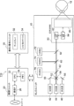
- FIG. 1 is a block diagram of an ophthalmic system 100.
- FIG. 1 is a schematic configuration diagram showing an overall configuration of an ophthalmologic apparatus 110.
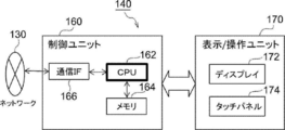
- FIG. 4 is a block diagram of an electrical configuration of a management server 140.
- FIG. 3 is a block diagram of functions of a CPU 162 of a management server 140.
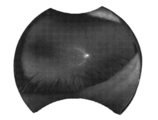
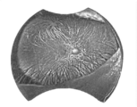
- FIG. It is a flowchart of an image processing program. It is the figure which showed the 1st fundus image (R color fundus image). It is the figure which showed the 2nd fundus image (G color fundus image). It is the figure which showed the choroidal blood vessel image in which the choroidal blood vessel was made relatively conspicuous. It is the figure which showed the choroidal blood vessel image with which the choroidal blood vessel was emphasized.
- SLO scanning laser ophthalmoscope
- an ophthalmic system 100 includes an ophthalmologic apparatus 110, an axial length measuring apparatus 120, a management server apparatus (hereinafter referred to as “management server”) 140, and an image display apparatus (hereinafter referred to as “image viewer”). 150).
- the ophthalmologic apparatus 110 acquires a fundus image.
- the axial length measuring device 120 measures the axial length of the patient.
- the management server 140 stores a plurality of fundus images and axial lengths obtained by photographing the fundus of a plurality of patients by the ophthalmologic apparatus 110 in correspondence with the patient ID.
- the image viewer 150 displays the fundus image acquired by the management server 140.
- the ophthalmologic apparatus 110, the axial length measuring apparatus 120, the management server 140, and the image viewer 150 are connected to each other via the network 130.
- other ophthalmic devices testing devices such as visual field measurement and intraocular pressure measurement
- diagnostic support devices that perform image analysis using artificial intelligence are connected via the network 130 to the ophthalmic device 110, the axial length measuring device 120, and the management.
- the server 140 and the image viewer 150 may be connected.
- the ophthalmologic apparatus 110 includes a control unit 20, a display / operation unit 30, and an SLO unit 40, and images the posterior eye portion (fundus) of the eye 12 to be examined.
- the control unit 20 includes a CPU 22, a memory 24, a communication interface (I / F) 26, and the like.
- the display / operation unit 30 is a graphic user interface that displays an image obtained by shooting and receives various instructions including an instruction for shooting, and includes a display 32 and a touch panel 34.
- the SLO unit 40 includes a light source 42 for G light (green light: wavelength 530 nm), a light source 44 for R light (red light: wavelength 650 nm), and a light source 46 for IR light (infrared light (near infrared light): wavelength 800 nm). ing.
- the light sources 42, 44, 46 emit respective lights as instructed by the control unit 20.
- the R light source is a visible light having a wavelength of 630 nm to 780 nm
- the IR light source is a laser light source that emits near infrared light having a wavelength of 780 nm or more.
- the SLO unit 40 includes optical systems 50, 52, 54, and 56 that guide light reflected from or transmitted through the light sources 42, 44, and 46 to one optical path.
- the optical systems 50 and 56 are mirrors, and the optical systems 52 and 54 are beam splitters.
- the G light is reflected by the optical systems 50 and 54, the R light is transmitted through the optical systems 52 and 54, and the IR light is reflected by the optical systems 52 and 56 and guided to one optical path.
- the SLO unit 40 includes a wide-angle optical system 80 that scans light from the light sources 42, 44, and 46 across the posterior segment (fundus) of the eye 12 to be examined in a two-dimensional manner.
- the SLO unit 40 includes a beam splitter 58 that reflects G light and transmits other light than the G light in the light from the posterior segment (fundus) of the eye 12 to be examined.
- the SLO unit 40 includes a beam splitter 60 that reflects R light and transmits light other than the R light out of the light transmitted through the beam splitter 58.
- the SLO unit 40 includes a beam splitter 62 that reflects IR light out of the light transmitted through the beam splitter 60.
- the SLO unit 40 detects the G light detecting element 72 that detects the G light reflected by the beam splitter 58, the R light detecting element 74 that detects the R light reflected by the beam splitter 60, and the IR light reflected by the beam splitter 62.
- IR light detecting element 76 is provided.
- the wide-angle optical system 80 includes an X-direction scanning device 82 composed of a polygon mirror that scans light from the light sources 42, 44, and 46 in the X direction, and a Y-direction scanning device 84 composed of a galvanometer mirror that scans in the Y direction. And an optical system 86 that includes a slit mirror and an elliptical mirror (not shown) and makes the scanned light have a wide angle.
- the fundus viewing angle (FOV: Field of View) can be set larger than that of the conventional technique, and a fundus region wider than that of the conventional technique can be imaged.
- the external light irradiation angle from the outside of the subject eye 12 is approximately 120 degrees (substantially by irradiating the fundus of the subject eye 12 with scanning light with the center O of the eyeball of the subject eye 12 as a reference position).
- a wide fundus region of about 200 degrees (with an internal light irradiation angle that can be photographed) can be photographed.
- the optical system 86 may have a configuration using a plurality of lens groups instead of the slit mirror and the elliptical mirror.
- Each scanning device of the X direction scanning device 82 and the Y direction scanning device 84 may use a two-dimensional scanner configured using a MEMS mirror.
- the horizontal direction is the “X direction”
- the vertical direction to the horizontal plane is the “Y direction”
- the center of the pupil of the anterior eye portion of the eye 12 to be tested is connected to the center of the eyeball.
- Let the direction be the “Z direction”. Therefore, the X direction, the Y direction, and the Z direction are perpendicular to each other.
- a color fundus image is obtained by photographing the fundus of the eye 12 simultaneously with G light and R light. More specifically, the control unit 20 controls the light sources 42 and 44 so as to emit light simultaneously, and the G light and the R light are scanned by the wide-angle optical system 80 over the fundus of the eye 12 to be examined. Then, the G light reflected from the fundus of the eye 12 to be examined is detected by the G light detection element 72, and image data of the second fundus image (G color fundus image) is generated by the image processing unit 182.
- the R light reflected from the fundus of the eye 12 to be examined is detected by the R light detection element 74, and image data of the first fundus image (R color fundus image) is generated by the CPU 22 of the ophthalmologic apparatus 110.
- image data of the IR fundus image is generated by the CPU 22 of the ophthalmologic apparatus 110.
- the CPU 22 of the ophthalmologic apparatus 110 mixes the first fundus image (R color fundus image) and the second fundus image (G color fundus image) at a predetermined ratio, and displays them on the display 32 as a color fundus image.
- a first fundus image (R color fundus image), a second fundus image (G color fundus image), or an IR fundus image may be displayed.
- the image data of the first fundus image (R color fundus image), the image data of the second fundus image (G color fundus image), and the image data of the IR fundus image are sent from the ophthalmologic apparatus 110 to the management server 140 via the communication IF 26. Is done.
- the fundus of the eye 12 to be examined is simultaneously photographed with the G light and the R light, so that each position of the first fundus image (R color fundus image) and the second fundus image (G color fundus image corresponding to this position) are obtained. ) Is the same position on the fundus.
- the 1 has two modes of a first mode and a second mode for measuring the axial length, which is the length in the axial direction (Z direction) of the eye 12 to be examined.
- the first mode after light from a light source (not shown) is guided to the eye 12 to be examined, interference light between the reflected light from the fundus and the reflected light from the cornea is received, and an interference signal indicating the received interference light is generated. Based on this, the axial length is measured.
- the second mode is a mode for measuring the axial length using an ultrasonic wave (not shown).
- the axial length measurement device 120 transmits the axial length measured in the first mode or the second mode to the management server 140.
- the axial length may be measured in the first mode and the second mode, and in this case, the average of the axial length measured in both modes is transmitted to the management server 140 as the axial length.
- the axial length is stored as patient information in the management server 140 as one of patient data, and is also used for fundus image analysis.
- the management server 140 includes a control unit 160 and a display / operation unit 170.
- the control unit 160 includes a computer including a CPU 162, a memory 164 as a storage device, a communication interface (I / F) 166, and the like.
- the memory 164 stores an image processing program.
- the display / operation unit 170 is a graphic user interface that displays an image and receives various instructions, and includes a display 172 and a touch panel 174.
- the image processing program has an image processing function, a display control function, and a processing function.
- the CPU 162 executes the image processing program having these functions, the CPU 162 functions as an image processing unit 182, a display control unit 184, and a processing unit 186, as shown in FIG.
- the CPU 162 of the management server 140 executes the image processing program, thereby realizing the image processing shown in the flowchart of FIG.
- the image processing program starts when image data of a fundus image obtained by photographing the fundus of the eye 12 to be examined by the ophthalmic apparatus 110 is transmitted from the ophthalmic apparatus 110 and received by the management server 140.
- the processing unit 186 reads image data of the first fundus image (R color fundus image) from the image data of the fundus image received from the ophthalmologic apparatus 110 in step 202 of FIG. In step 204, the processing unit 186 reads out image data of the second fundus image (G color fundus image) from the image data of the fundus image received from the ophthalmologic apparatus 110.
- the eye structure is such that the vitreous body is covered with a plurality of layers having different structures.
- the plurality of layers include the retina, choroid, and sclera from the innermost side to the outer side on the vitreous side.
- the R light passes through the retina and reaches the choroid. Therefore, the first fundus image (R color fundus image) includes information on blood vessels (retinal blood vessels) existing in the retina and information on blood vessels (choroidal blood vessels) existing in the choroid.
- G light reaches only the retina. Therefore, the second fundus image (G color fundus image) includes only information on blood vessels (retinal blood vessels) existing in the retina.
- the image processing unit 182 extracts a retinal blood vessel from the second fundus image (G color fundus image) by performing black hat filter processing on the second fundus image (G color fundus image).
- the black hat filter process is a filter process that extracts black lines.
- the second fundus image (G color fundus image) is imaged, and the original image data is subjected to N times (N is an integer of 1 or more) expansion processing and N time contraction processing.
- N is an integer of 1 or more expansion processing and N time contraction processing.
- This is a process for obtaining a difference from the image data obtained by the process. Since the retinal blood vessel absorbs irradiation light (not only G light but also R light or IR light), the fundus image is photographed blacker than the periphery of the blood vessel. Therefore, retinal blood vessels can be extracted by performing black hat filter processing on the fundus image.
- the image processing unit 182 removes the retinal blood vessel extracted in step 206 from the first fundus image (R color fundus image) by the inpainting process.
- the retinal blood vessels are made inconspicuous in the first fundus image (R color fundus image). More specifically, each position of the retinal blood vessel extracted from the second fundus image (G color fundus image) is specified in the first fundus image (R color fundus image), and the first fundus image (R) at the specified position is specified.
- the pixel value of the pixel in the color fundus image) is processed so that the difference from the average value of the pixels around the pixel falls within a predetermined range (for example, 0).
- the retinal blood vessel is made inconspicuous in the first fundus image (R color fundus image) in which the retinal blood vessel and the choroidal blood vessel exist, and as a result, the choroid blood vessel in the first fundus image (R color fundus image). Can be made relatively conspicuous.
- a choroidal blood vessel image in which the choroidal blood vessels are relatively conspicuous is obtained.
- step 210 the image processing unit 182 performs CLAHE (Contrast Limited Adaptive Equalization (Adaptation with Restriction of Contrast) on the image data of the first fundus image (R color fundus image) in which choroidal blood vessels are relatively conspicuous.
- CLAHE Contrast Limited Adaptive Equalization
- the choroidal blood vessels are emphasized in the first fundus image (R color fundus image).
- FIG. 6D a choroidal blood vessel image in which the choroidal blood vessels are emphasized is obtained.
- the image processing unit 182 executes choroid analysis processing using image data of a choroidal blood vessel image in which the choroidal blood vessel is emphasized. For example, a vortex vein (Vortex Vein) position detection process, an analysis process of orientation in the running direction of the choroidal blood vessel, and the like.
- a vortex vein Vortex Vein
- an analysis process of orientation in the running direction of the choroidal blood vessel and the like.
- step 214 the processing unit 186 stores the choroidal blood vessel image and choroid analysis data in the memory 164.
- step 214 When the processing in step 214 is completed, the image processing program ends.
- a doctor operating the image viewer 150 may want to know the state of choroidal blood vessels when diagnosing a patient.
- the doctor transmits an instruction to transmit data on the display screen in the choroidal blood vessel analysis mode to the management server 140 via the image viewer 150.
- the display control unit 184 of the management server 140 Upon receiving an instruction from the image viewer 150, the display control unit 184 of the management server 140 creates display screen data in the choroidal blood vessel analysis mode.
- the display screen data in the choroidal blood vessel analysis mode will be described.
- personal information of the patient is input to the ophthalmologic apparatus 110.
- the personal information includes the patient ID, name, age, visual acuity, and the like.
- information indicating whether the eye for photographing the fundus is the right eye or the left eye is also input.
- the photographing date and time is also input.
- personal information, right eye / left eye information, and shooting date / time data are transmitted from the ophthalmologic apparatus 110 to the management server 140.
- the display control unit 184 displays, as data on the display screen in the choroidal blood vessel analysis mode, personal information including the axial length, photographing date / time, right eye / left eye information, first fundus image (R color fundus image), second Each data of the fundus image (G color fundus image) and the choroidal blood vessel image is read from the memory 164, and the display screen 300 of the choroidal blood vessel analysis mode shown in FIG. 7 is created.
- the management server 140 that created the display screen 300 transmits data of the display screen 300 in the choroidal blood vessel analysis mode to the image viewer 150.
- the image viewer 150 that has received the data on the display screen in the choroidal blood vessel analysis mode displays FIG. 7 on the display 156 of the image viewer 150 based on the data on the display screen in the choroidal blood vessel analysis mode.
- the display screen 300 in the choroidal blood vessel analysis mode shown in FIG. 7 will be described.
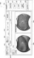
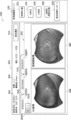
- the choroidal blood vessel analysis mode display screen 300 shown in FIG. 7 has a personal information display field 302 for displaying personal information of a patient, an image display field 320, and a choroid analysis tool display field 330.
- the personal information display field 302 includes a patient ID display field 304, a patient name display field 306, an age display field 308, an axial length display field 310, and a visual acuity display field 312.
- the image display column 320 includes an imaging date display column 322N1, a right eye information display column 324R, a left eye information display column 324L, an RG image display column 326, and a choroidal blood vessel image display column 328.
- the RG image is composed of the first fundus image (R color fundus image) and the second fundus image (G color fundus image) at a predetermined ratio (for example, 1: 1) of each pixel value. It is an image obtained by this.
- the choroid analysis tool display field 330 is a plurality of choroid analysis tools that instruct the image viewer 150 to perform processing, for example, a vortex vein position analysis icon 332, a symmetry icon 334, a blood vessel diameter icon 336, a vortex vein / macular / papillae icon. 338 and a choroid analysis report icon 340.
- the vortex vein position analysis icon 332 instructs to specify the vortex vein position.
- Symmetry icon 334 indicates that the symmetry of the vortex vein is to be analyzed.
- the blood vessel diameter icon 336 instructs to execute a tool for analyzing the diameter of the choroid blood vessel.
- a vortex vein / macular / papillae icon 338 directs analysis of the location between the vortex vein, the macula, and the optic disc.
- the choroid analysis report icon 340 instructs to display the choroid analysis report.
- an RG image and a choroid image when the fundus of the patient identified by the patient ID: 123456 is captured on January 1, 2016 are displayed.
- a choroidal blood vessel image is generated.
- the retinal blood vessel is removed from the R image by image processing, and a choroidal blood vessel image in which only the choroidal blood vessel exists is generated. Therefore, it is possible to reduce the influence of the retinal blood vessel on the analysis of the choroidal blood vessel.
- step 212 in FIG. 5 the display control unit 184 executes the process in step 214.
- the technology of the present disclosure is not limited to this.
- the display control unit 184 Processing may be executed.
- the ophthalmologic apparatus 110 acquires a fundus image having an internal light irradiation angle of about 200 degrees, which is an angle from the center of the eyeball.
- the technology of the present disclosure is not limited thereto, and may be a fundus image obtained by a fundus camera, or a fundus image captured by various ophthalmologic apparatuses such as an ophthalmologic apparatus or a fundus camera having an internal irradiation angle of 100 ° or less. The technique may be applied.
- the management server 140 executes the image processing program.
- the technology of the present disclosure is not limited to this.
- the ophthalmologic apparatus 110 or the image viewer 150 may execute the image processing program.
- the image processing program is stored in the memory 24, and the choroidal blood vessel image and choroid analysis data in step 214 are stored in the memory 24.
- the image processing program is stored in the memory of the image viewer 150, and the choroidal blood vessel image and choroid analysis data in step 214 are stored in the memory of the image viewer 150. Saved.
- the ophthalmologic system 100 including the ophthalmologic apparatus 110, the axial length measuring apparatus 120, the management server 140, and the image viewer 150 has been described as an example, but the technology of the present disclosure is not limited thereto.
- the ocular axial length measuring device 120 may be omitted, and the ophthalmic apparatus 110 may further have the function of the axial axial length measuring device 120.
- the ophthalmologic apparatus 110 may further have at least one function of the management server 140 and the image viewer 150.
- the management server 140 can be omitted.
- the image processing program is executed by the ophthalmologic apparatus 110 or the image viewer 150.
- the image viewer 150 can be omitted.
- the management server 140 may be omitted, and the image viewer 150 may execute the function of the management server 140.
- an R fundus image captured with R light is used as the first fundus image, but an IR fundus image captured with IR light may be used. That is, since R light having a wavelength of 630 nm to 780 nm or IR light having a wavelength of 780 nm or more is used, the light reaches not only the retina but also the choroid. In particular, with IR light, it is possible to take images up to a deep region of the choroid.
- the fundus image is obtained by photographing the fundus of the eye 12 to be examined simultaneously with the G light and the R light.
- the technology of the present disclosure is not limited to this.
- the fundus of the eye 12 to be examined may be photographed while being shifted in time with the G light and the R light.
- step 208 is executed after the first fundus image (R color fundus image) and the second fundus image (G color fundus image) are aligned.
- the choroidal blood vessel image is generated based on the first fundus image (R color fundus image) and the second fundus image (G color fundus image), but the technology of the present disclosure is not limited to this.
- a choroidal blood vessel image may be generated.
- FIG. 9 shows image processing for generating a choroidal blood vessel image based on the fundus image (R color fundus image).
- the fundus of the subject eye 12 is photographed simultaneously with the G light and the R light.
- the fundus image (R color) is photographed by photographing the fundus of the subject eye 12 only with the R light. A fundus image) is obtained.
- the image processing program in FIG. 9 also starts when image data of a fundus image (R color fundus image) is transmitted from the ophthalmic apparatus 110 and received by the management server 140.
- image processing in FIG. 9 includes the same processing as the image processing in FIG. 5, so the same processing is denoted by the same reference numerals and detailed description thereof is omitted.
- the image processing unit 182 performs black hat filter processing on the fundus image (R color fundus image), thereby generating a fundus image (R color fundus image). Extract retinal blood vessels.
- the fundus image includes information on blood vessels (retinal blood vessels) existing in the retina and information on blood vessels (choroidal blood vessels) existing in the choroid.
- the black hat filter process is performed on the fundus image (R color fundus image)
- only retinal blood vessel information is extracted. Since the retinal blood vessel absorbs not only G light but also R light, the fundus image is photographed in black compared to the periphery of the blood vessel. Therefore, retinal blood vessels can be extracted by performing black hat filter processing on the fundus image.
- steps 208 to 214 are executed.
- the fundus image (R color fundus image) is obtained by photographing the fundus of the eye 12 to be examined using only R light, and the choroidal blood vessel image is obtained from the fundus image (R color fundus image). Can be generated.
- the present invention is not limited to photographing with R light, and an IR fundus image photographed with IR light may be used.
Landscapes
- Health & Medical Sciences (AREA)
- Life Sciences & Earth Sciences (AREA)
- Engineering & Computer Science (AREA)
- Physics & Mathematics (AREA)
- General Health & Medical Sciences (AREA)
- Medical Informatics (AREA)
- Public Health (AREA)
- Heart & Thoracic Surgery (AREA)
- Surgery (AREA)
- Veterinary Medicine (AREA)
- Animal Behavior & Ethology (AREA)
- Molecular Biology (AREA)
- Biomedical Technology (AREA)
- Ophthalmology & Optometry (AREA)
- Biophysics (AREA)
- Theoretical Computer Science (AREA)
- General Physics & Mathematics (AREA)
- Computer Vision & Pattern Recognition (AREA)
- Radiology & Medical Imaging (AREA)
- Nuclear Medicine, Radiotherapy & Molecular Imaging (AREA)
- Signal Processing (AREA)
- Epidemiology (AREA)
- Primary Health Care (AREA)
- Quality & Reliability (AREA)
- Geometry (AREA)
- Eye Examination Apparatus (AREA)
- Image Processing (AREA)
Abstract
網膜血管が、脈絡血管の解析に影響することを少なくする。 第1眼底画像(R色眼底画像)の及び第2眼底画像(G色眼底画像)の画像データを読み出し、第2眼底画像から網膜血管を抽出し、第1眼底画像から網膜血管を除去し、脈絡膜血管が相対的に目立たされた第1眼底画像において、脈絡膜血管を強調する。これにより、脈絡膜血管が強調された脈絡膜血管画像が得られる。
Description
本開示の技術は、画像処理方法、プログラム、眼科装置、及び脈絡膜血管画像生成方法に関する。
特許第5739323号には、網膜血管の特徴を強調することが開示されている。
本開示の技術の第1の態様の画像処理方法は、第1波長の第1の光で眼底を撮影して得た第1眼底画像と、前記第1波長より波長が短い第2波長の第2の光で前記眼底を撮影して得た第2眼底画像とに基づいて、脈絡膜血管画像を生成することを含む。
本開示の技術の第2の態様のプログラムは、コンピュータに第1の態様の画像処理方法を実行させる。
本開示の技術の第3の態様の眼科装置は、プロセッサに画像処理方法を実行させるためのプログラムを記憶する記憶装置と、前記記憶装置に記憶されているプログラムを実行することにより前記画像処理方法を実行する処理装置と、を備える眼科装置であって、前記画像処理方法は、第1の態様の画像処理方法である。
本開示の技術の第4の態様の脈絡膜血管画像生成方法は、波長が630nm以上の光で眼底を撮影することにより、眼底画像を取得するステップと、前記眼底画像から、網膜血管を抽出するステップと、前記眼底画像から、前記網膜血管を消去することにより、脈絡膜血管画像を生成するステップと、を含む。
以下、図面を参照して本発明の実施の形態を詳細に説明する。なお、以下では、説明の便宜上、走査型レーザ検眼鏡(Scanning Laser Ophthalmoscope)を「SLO」と称する。
図1を参照して、眼科システム100の構成を説明する。図1に示すように、眼科システム100は、眼科装置110と、眼軸長測定装置120と、管理サーバ装置(以下、「管理サーバ」という)140と、画像表示装置(以下、「画像ビューワ」という)150と、を備えている。眼科装置110は、眼底画像を取得する。眼軸長測定装置120は、患者の眼軸長を測定する。管理サーバ140は、眼科装置110によって複数の患者の眼底が撮影されることにより得られた複数の眼底画像及び眼軸長を、患者のIDに対応して記憶する。画像ビューワ150は、管理サーバ140により取得した眼底画像を表示する。
眼科装置110、眼軸長測定装置120、管理サーバ140、画像ビューワ150は、ネットワーク130を介して、相互に接続されている。
なお、他の眼科機器(視野測定、眼圧測定などの検査機器)や人工知能を用いた画像解析を行う診断支援装置がネットワーク130を介して、眼科装置110、眼軸長測定装置120、管理サーバ140、及び画像ビューワ150に接続されていてもよい。
なお、他の眼科機器(視野測定、眼圧測定などの検査機器)や人工知能を用いた画像解析を行う診断支援装置がネットワーク130を介して、眼科装置110、眼軸長測定装置120、管理サーバ140、及び画像ビューワ150に接続されていてもよい。
次に、図2を参照して、眼科装置110の構成を説明する。図2に示すように、眼科装置110は、制御ユニット20、表示/操作ユニット30、及びSLOユニット40を備え、被検眼12の後眼部(眼底)を撮影する。
制御ユニット20は、CPU22、メモリ24、及び通信インターフェース(I/F)26等を備えている。表示/操作ユニット30は、撮影されて得られた画像を表示したり、撮影の指示を含む各種指示を受け付けたりするグラフィックユーザインターフェースであり、ディスプレイ32及びタッチパネル34を備えている。
SLOユニット40は、G光(緑色光:波長530nm)の光源42、R光(赤色光:波長650nm)の光源44、IR光(赤外線(近赤外光):波長800nm)の光源46を備えている。光源42、44、46は、制御ユニット20により命令されて、各光を発する。R光の光源は波長630nm~780nmの可視光、IR光の光源は波長780nm以上の近赤外光を発するレーザ光源が用いられる。
SLOユニット40は、光源42、44、46からの光を、反射又は透過して1つの光路に導く光学系50、52、54、56を備えている。光学系50、56は、ミラーであり、光学系52、54は、ビームスプリッタ―である。G光は、光学系50、54で反射し、R光は、光学系52、54を透過し、IR光は、光学系52、56で反射して、それぞれ1つの光路に導かれる。
SLOユニット40は、光源42、44、46からの光を、被検眼12の後眼部(眼底)に渡って、2次元状に走査する広角光学系80を備えている。SLOユニット40は、被検眼12の後眼部(眼底)からの光の内、G光を反射し且つG光以外を透過するビームスプリッタ58を備えている。SLOユニット40は、ビームスプリッタ58を透過した光の内、R光を反射し且つR光以外を透過するビームスプリッタ60を備えている。SLOユニット40は、ビームスプリッタ60を透過した光の内、IR光を反射するビームスプリッタ62を備えている。SLOユニット40は、ビームスプリッタ58により反射したG光を検出するG光検出素子72、ビームスプリッタ60により反射したR光を検出するR光検出素子74、及びビームスプリッタ62により反射したIR光を検出するIR光検出素子76を備えている。
広角光学系80は、光源42、44、46からの光を、X方向に走査するポリゴンミラーで構成されたX方向走査装置82、Y方向に走査するガルバノミラーで構成されたY方向走査装置84、及び、図示しないスリットミラーおよび楕円鏡を含み、走査された光を、広角にする光学系86を備えている。光学系86により、眼底の視野角(FOV:Field of View)を従来の技術より大きな角度とし、従来の技術より広範囲の眼底領域を撮影することができる。具体的には、被検眼12の外部からの外部光照射角で約120度(被検眼12の眼球の中心Oを基準位置として、被検眼12の眼底が走査光により照射されることで実質的に撮影可能な内部光照射角で、200度程度)の広範囲の眼底領域を撮影することができる。光学系86は、スリットミラーおよび楕円鏡に代えて、複数のレンズ群を用いた構成でもよい。X方向走査装置82及びY方向走査装置84の各走査装置はMEMSミラーを用いて構成された二次元スキャナを用いてもよい。
光学系86としてスリットミラーおよび楕円鏡を含むシステムを用いる場合には、国際出願PCT/JP2014/084619や国際出願PCT/JP2014/084630に記載された楕円鏡を用いたシステムを用いる構成でもよい。2014年12月26日に国際出願された国際出願PCT/JP2014/084619(国際公開WO2016/103484)の開示及び2014年12月26日に国際出願された国際出願PCT/JP2014/084630(国際公開WO2016/103489)の開示の各々は、その全体が参照により本明細書に取り込まれる。
なお、眼科装置110が水平面に設置された場合の水平方向を「X方向」、水平面に対する垂直方向を「Y方向」とし、被検眼12の前眼部の瞳孔の中心と眼球の中心とを結ぶ方向を「Z方向」とする。従って、X方向、Y方向、およびZ方向は互いに垂直である。
カラー眼底画像は、G光及びR光で同時に被検眼12の眼底が撮影されることにより、得られる。より詳細には、制御ユニット20が、同時に発光するように光源42、44を制御し、被検眼12の眼底に渡って、広角光学系80によりG光及びR光が走査される。そして、被検眼12の眼底から反射されたG光がG光検出素子72により検出され、第2眼底画像(G色眼底画像)の画像データが画像処理部182で生成される。同様に、被検眼12の眼底から反射されたR光がR光検出素子74により検出され、第1眼底画像(R色眼底画像)の画像データが、眼科装置110のCPU22により生成される。また、IR光が照射された場合は、被検眼12の眼底から反射されたIR光がIR光検出素子76により検出され、IR眼底画像の画像データが眼科装置110のCPU22により生成される。
眼科装置110のCPU22は、第1眼底画像(R色眼底画像)と第2眼底画像(G色眼底画像)とを所定の比率で混合し、カラー眼底画像として、ディスプレイ32に表示する。なお、カラー眼底画像ではなく、第1眼底画像(R色眼底画像)、第2眼底画像(G色眼底画像)、あるいは、IR眼底画像を表示するようにしてもよい。
第1眼底画像(R色眼底画像)の画像データ、第2眼底画像(G色眼底画像)の画像データ、IR眼底画像の画像データは、通信IF26を介して眼科装置110から管理サーバ140へ送付される。
第1眼底画像(R色眼底画像)の画像データ、第2眼底画像(G色眼底画像)の画像データ、IR眼底画像の画像データは、通信IF26を介して眼科装置110から管理サーバ140へ送付される。
このようにG光及びR光で同時に被検眼12の眼底が撮影されるので、第1眼底画像(R色眼底画像)の各位置と、この位置に対応する第2眼底画像(G色眼底画像)における位置とは、眼底において同じ位置である。
図1の眼軸長測定装置120は、被検眼12の眼軸方向(Z方向)の長さである眼軸長を測定する第1のモードと第2のモードとの2つのモードを有する。第1のモードは、図示しない光源からの光を被検眼12に導光した後、眼底からの反射光と角膜からの反射光との干渉光を受光し、受光した干渉光を示す干渉信号に基づいて眼軸長を測定する。第2のモードは、図示しない超音波を用いて眼軸長を測定するモードである。眼軸長測定装置120は、第1のモード又は第2のモードにより測定された眼軸長を管理サーバ140に送信する。第1のモード及び第2のモードにより眼軸長を測定してもよく、この場合には、双方のモードで測定された眼軸長の平均を眼軸長として管理サーバ140に送信する。
眼軸長は患者のデータの一つとして管理サーバ140に患者情報として保存されるとともに、眼底画像解析にも利用される。
眼軸長は患者のデータの一つとして管理サーバ140に患者情報として保存されるとともに、眼底画像解析にも利用される。
次に、図3を参照して、管理サーバ140の構成を説明する。図3に示すように、管理サーバ140は、制御ユニット160、及び表示/操作ユニット170を備えている。制御ユニット160は、CPU162を含むコンピュータ、記憶装置であるメモリ164、及び通信インターフェース(I/F)166等を備えている。なお、メモリ164には、画像処理プログラムが記憶されている。表示/操作ユニット170は、画像を表示したり、各種指示を受け付けたりするグラフィックユーザインターフェースであり、ディスプレイ172及びタッチパネル174を備えている。
画像ビューワ150の構成は、管理サーバ140と同様であるので、その説明を省略する。
次に、図4を参照して、管理サーバ140のCPU162が画像処理プログラムを実行することで実現される各種機能について説明する。画像処理プログラムは、画像処理機能、表示制御機能、及び処理機能を備えている。CPU162がこの各機能を有する画像処理プログラムを実行することで、CPU162は、図4に示すように、画像処理部182、表示制御部184、及び処理部186として機能する。
次に、図5を用いて、管理サーバ140による画像処理を詳細に説明する。管理サーバ140のCPU162が画像処理プログラムを実行することで、図5のフローチャートに示された画像処理が実現される。
画像処理プログラムは、眼科装置110により被検眼12の眼底が撮影されて得たられた眼底画像の画像データが、眼科装置110から送信され、管理サーバ140により受信された時にスタートする。
画像処理プログラムがスタートすると、図5のステップ202で、処理部186は、眼科装置110から受信した眼底画像の画像データの中から、第1眼底画像(R色眼底画像)の画像データを読み出す。ステップ204で、処理部186は、眼科装置110から受信した眼底画像の画像データの中から第2眼底画像(G色眼底画像)の画像データを読み出す。
ここで、第1眼底画像(R色眼底画像)と第2眼底画像(G色眼底画像)とに含まれる情報を説明する。
眼の構造は、硝子体を、構造が異なる複数の層が覆うようになっている。複数の層には、硝子体側の最も内側から外側に、網膜、脈絡膜、強膜が含まれる。R光は、網膜を通過して脈絡膜まで到達する。よって、第1眼底画像(R色眼底画像)には、網膜に存在する血管(網膜血管)の情報と脈絡膜に存在する血管(脈絡膜血管)の情報とが含まれる。これに対し、G光は、網膜までしか到達しない。よって、第2眼底画像(G色眼底画像)には、網膜に存在する血管(網膜血管)の情報のみが含まれる。
ステップ206で、画像処理部182は、ブラックハットフィルタ処理を第2眼底画像(G色眼底画像)に施すことにより、第2眼底画像(G色眼底画像)から網膜血管を抽出する。ブラックハットフィルタ処理は黒い線を抽出するフィルタ処理である。
ブラックハットフィルタ処理は、第2眼底画像(G色眼底画像)の画像データと、この原画像データに対してN回(Nは1以上の整数)の膨張処理及びN回の収縮処理を行うクロージング処理により得られる画像データとの差分をとる処理である。網膜血管は照射光(G光だけでなく,R光あるいはIR光)を吸収するため眼底画像では血管の周囲に比べて黒く撮影される。そのため、ブラックハットフィルタ処理を眼底画像に施すことにより、網膜血管を抽出することができる。
ステップ208で、画像処理部182は、第1眼底画像(R色眼底画像)から、インペインティング処理により、ステップ206で抽出した網膜血管を除去する。具体的には、第1眼底画像(R色眼底画像)において、網膜血管を目立たせなくする。より詳細には、第2眼底画像(G色眼底画像)から抽出した網膜血管の各位置を、第1眼底画像(R色眼底画像)において特定し、特定された位置の第1眼底画像(R色眼底画像)における画素の画素値を、当該画素の周囲の画素の平均値との差が所定範囲(例えば、0)になるように、処理する。
このように、網膜血管と脈絡膜血管とが存在する第1眼底画像(R色眼底画像)において、網膜血管を目立たせなくするので、結果、第1眼底画像(R色眼底画像)において、脈絡膜血管を、相対的に目立たせることができる。これにより図6Cに示すように、脈絡膜血管が相対的に目立たされた脈絡膜血管画像が得られる。
ステップ210で、画像処理部182は、脈絡膜血管が相対的に目立たされた第1眼底画像(R色眼底画像)の画像データに対し、CLAHE(Contrast Limited Adaptive Histogram Equalization(コントラストに制限を付けた適応ヒストグラム均等化))処理を施すことにより、第1眼底画像(R色眼底画像)において、脈絡膜血管を強調する。これにより、図6Dに示すように、脈絡膜血管が強調された脈絡膜血管画像が得られる。
ステップ212で、画像処理部182は、脈絡膜血管が強調された脈絡膜血管画像の画像データを用いた脈絡膜解析処理を実行する。例えば、渦静脈(Vortex Vein)位置検出処理や脈絡膜血管の走行方向の配向性の解析処理等である。
ステップ214で、処理部186は、脈絡膜血管画像、脈絡膜解析データを、メモリ164に保存する。
ステップ214の処理が終了すると、画像処理プログラムが終了する。
ところで、画像ビューワ150を操作している医者が、患者を診断する際に、脈絡膜血管の状態を知りたいと考える場合がある。この場合、医者は、画像ビューワ150を介して、管理サーバ140に、脈絡膜血管解析モードの表示画面のデータを送信する指示を送信する。
画像ビューワ150から指示を受けた管理サーバ140の表示制御部184は、脈絡膜血管解析モードの表示画面のデータを作成する。
脈絡膜血管解析モードの表示画面のデータを説明する。患者の眼底が撮影される際には、眼科装置110には、患者の個人情報が入力される。個人情報には、患者のID、氏名、年齢、及び視力等が含まれる。また、患者の眼底が撮影される際には、眼底が撮影される眼は、右眼なのか左眼を示す情報も入力される。更に、患者の眼底が撮影される際には、撮影日時も入力される。眼科装置110から管理サーバ140には、眼底画像の画像データの他に、個人情報、右眼・左眼の情報、及び、撮影日時のデータが送信される。
表示制御部184は、脈絡膜血管解析モードの表示画面のデータとして、眼軸長を含めた個人情報、撮影日時、右眼・左眼の情報、第1眼底画像(R色眼底画像)、第2眼底画像(G色眼底画像)、及び脈絡膜血管画像の各データをメモリ164から読み出し、図7に示す脈絡膜血管解析モードの表示画面300を作成する。
表示画面300を作成した管理サーバ140は、画像ビューワ150に、脈絡膜血管解析モードの表示画面300のデータを送信する。脈絡膜血管解析モードの表示画面のデータを受信した画像ビューワ150は、脈絡膜血管解析モードの表示画面のデータに基づいて、図7を、画像ビューワ150のディスプレイ156に表示する。
ここで、図7に示す脈絡膜血管解析モードの表示画面300を説明する。図7に示すように、図7に示す脈絡膜血管解析モードの表示画面300は、患者の個人情報を表示する個人情報表示欄302、画像表示欄320、及び脈絡膜解析ツール表示欄330を有する。
個人情報表示欄302は、患者ID表示欄304、患者氏名表示欄306、年齢表示欄308、眼軸長表示欄310、及び視力表示欄312を有する。
画像表示欄320は、撮影日付表示欄322N1、右眼情報表示欄324R、左眼情報表示欄324L、RG画像表示欄326、及び脈絡膜血管画像表示欄328を有する。なお、RG画像は、第1眼底画像(R色眼底画像)と第2眼底画像(G色眼底画像)とを、各画素値の大きさを所定の割合(例えば、1:1)で合成することにより得られる画像である。
脈絡膜解析ツール表示欄330は、画像ビューワ150に対して処理を指示する複数の脈絡膜解析ツール、例えば、渦静脈位置解析アイコン332、対称性アイコン334、血管径アイコン336、渦静脈・黄斑/乳頭アイコン338、及び脈絡膜解析レポートアイコン340を備える。渦静脈位置解析アイコン332は、渦静脈位置を特定することを指示する。対称性アイコン334は、渦静脈の対称性を解析することを指示する。血管径アイコン336は、脈絡血管の径を解析するツールを実行することを指示する。渦静脈・黄斑/乳頭アイコン338は、渦静脈、黄斑、及び視神経乳頭の間の位置を解析することを指示する。脈絡膜解析レポートアイコン340は、脈絡膜解析レポートを表示することを指示する。
図7に示す例は、患者ID:123456により識別される患者の眼底が、撮影日が2016年1月1日に撮影された場合のRG画像及び脈絡膜画像が表示される。
一方、当該患者の眼底が、その後、例えば、2017年1月1日、2018年1月1日に、撮影されて上記データが取得された場合には、図8に示すように、2016年1月1日、2017年1月1日、及び2018年1月1日の各撮影日毎にRG画像及び脈絡膜画像が表示される。撮影日付表示欄322N1、322N2、322N3にそれぞれ、撮影日の2016年1月1日、2017年1月1日、2018年1月1日が表示される。例えば、図8に示すように、2018年1月1日が表示された撮影日付表示欄322N3がクリックされると、2018年1月1日に撮影されて得られたRG画像及び脈絡膜画像が表示される。
以上説明したように本実施の形態では、脈絡血管画像を生成している。
ここで、従来、眼底を赤色光源で撮影したR画像には脈絡膜血管と網膜血管とが存在しており、脈絡血管を解析する場合に網膜血管が解析に影響する。
これに対し本実施の形態では、R画像から網膜血管を画像処理により除去し、脈絡膜血管のみが存在する脈絡膜血管画像を生成する。よって、網膜血管が、脈絡血管の解析に影響することを少なくすることができる。
次に、本開示の技術の種々の変形例を説明する。
<第1の変形例>
上記実施の形態では、図5のステップ212の後に、表示制御部184が、ステップ214の処理を実行する。本開示の技術はこれに限定されない。例えば、まず、ステップ212の処理が終了すると、画像処理プログラムが終了し、脈絡膜血管解析モードの表示画面のデータを送信する指示を管理サーバ140が受信した時に、表示制御部184が、ステップ214の処理を実行してもよい。
<第1の変形例>
上記実施の形態では、図5のステップ212の後に、表示制御部184が、ステップ214の処理を実行する。本開示の技術はこれに限定されない。例えば、まず、ステップ212の処理が終了すると、画像処理プログラムが終了し、脈絡膜血管解析モードの表示画面のデータを送信する指示を管理サーバ140が受信した時に、表示制御部184が、ステップ214の処理を実行してもよい。
<第2の変形例>
上記実施の形態では、眼科装置110により眼球中心からの角度である内部光照射角が200度程度の眼底画像を取得する例を説明した。本開示の技術はこれに限定されず、眼底カメラによる眼底画像でもよいし、例えば、内部照射角で100°以下の眼科装置あるいは眼底カメラなど、さまざまな眼科装置で撮影された眼底画像でも本開示の技術を適用してもよい。
上記実施の形態では、眼科装置110により眼球中心からの角度である内部光照射角が200度程度の眼底画像を取得する例を説明した。本開示の技術はこれに限定されず、眼底カメラによる眼底画像でもよいし、例えば、内部照射角で100°以下の眼科装置あるいは眼底カメラなど、さまざまな眼科装置で撮影された眼底画像でも本開示の技術を適用してもよい。
<第3の変形例>
上記実施の形態では、管理サーバ140が画像処理プログラムを実行する。本開示の技術はこれに限定されない。例えば、眼科装置110又は画像ビューワ150が画像処理プログラムを実行するようにしてもよい。眼科装置110が画像処理プログラムを実行する場合には、画像処理プログラムはメモリ24に記憶されており、ステップ214における脈絡膜血管画像、脈絡膜解析データは、メモリ24に保存される。また、画像ビューワ150が画像処理プログラムを実行する場合には、画像処理プログラムは、画像ビューワ150のメモリに記憶されており、ステップ214における脈絡膜血管画像、脈絡膜解析データは、画像ビューワ150のメモリに保存される。
上記実施の形態では、管理サーバ140が画像処理プログラムを実行する。本開示の技術はこれに限定されない。例えば、眼科装置110又は画像ビューワ150が画像処理プログラムを実行するようにしてもよい。眼科装置110が画像処理プログラムを実行する場合には、画像処理プログラムはメモリ24に記憶されており、ステップ214における脈絡膜血管画像、脈絡膜解析データは、メモリ24に保存される。また、画像ビューワ150が画像処理プログラムを実行する場合には、画像処理プログラムは、画像ビューワ150のメモリに記憶されており、ステップ214における脈絡膜血管画像、脈絡膜解析データは、画像ビューワ150のメモリに保存される。
<第4の変形例>
上記実施の形態では、眼科装置110、眼軸長測定装置120、管理サーバ140、及び画像ビューワ150を備えた眼科システム100を例として説明したが、本開示の技術はこれに限定されない。例えば、第1の例として、眼軸長測定装置120を省略し、眼科装置110が、眼軸長測定装置120の機能を更に有してもよい。また、第2の例として、眼科装置110が、管理サーバ140及び画像ビューワ150の少なくとも一方の機能を更に有してもよい。例えば、眼科装置110が管理サーバ140の機能を有する場合、管理サーバ140を省略することができる。この場合、画像処理プログラムは、眼科装置110又は画像ビューワ150が実行する。また、眼科装置110が画像ビューワ150の機能を有する場合、画像ビューワ150を省略することができる。第3の例として、管理サーバ140を省略し、画像ビューワ150が管理サーバ140の機能を実行するようにしてもよい。
上記実施の形態では、眼科装置110、眼軸長測定装置120、管理サーバ140、及び画像ビューワ150を備えた眼科システム100を例として説明したが、本開示の技術はこれに限定されない。例えば、第1の例として、眼軸長測定装置120を省略し、眼科装置110が、眼軸長測定装置120の機能を更に有してもよい。また、第2の例として、眼科装置110が、管理サーバ140及び画像ビューワ150の少なくとも一方の機能を更に有してもよい。例えば、眼科装置110が管理サーバ140の機能を有する場合、管理サーバ140を省略することができる。この場合、画像処理プログラムは、眼科装置110又は画像ビューワ150が実行する。また、眼科装置110が画像ビューワ150の機能を有する場合、画像ビューワ150を省略することができる。第3の例として、管理サーバ140を省略し、画像ビューワ150が管理サーバ140の機能を実行するようにしてもよい。
<第5の変形例>
上記実施の形態では、第1眼底画像としてR光で撮影されたR色眼底画像を用いているが、IR光で撮影されたIR眼底画像を用いてもよい。つまり、波長630nm~780nmのR光や波長780nm以上のIR光を用いるので、網膜だけでなく脈絡膜まで光が届く。特にIR光では脈絡膜の深い領域までの撮影できる。つまり、眼球の強膜側の脈絡膜の領域を撮影できる光を用いるので眼球の硝子体を覆い且つ硝子体側の最も内側から外側に位置する構造が異なる網膜及び脈絡膜を含む複数の層の内の当該脈絡膜まで光が届き、光が届く領域を撮影することができる。
上記実施の形態では、第1眼底画像としてR光で撮影されたR色眼底画像を用いているが、IR光で撮影されたIR眼底画像を用いてもよい。つまり、波長630nm~780nmのR光や波長780nm以上のIR光を用いるので、網膜だけでなく脈絡膜まで光が届く。特にIR光では脈絡膜の深い領域までの撮影できる。つまり、眼球の強膜側の脈絡膜の領域を撮影できる光を用いるので眼球の硝子体を覆い且つ硝子体側の最も内側から外側に位置する構造が異なる網膜及び脈絡膜を含む複数の層の内の当該脈絡膜まで光が届き、光が届く領域を撮影することができる。
<第6の変形例>
上記実施の形態では、眼底画像を、G光及びR光で同時に被検眼12の眼底を撮影することにより、得ている。本開示の技術はこれに限定されない。例えば、G光とR光とで時間的にずらして被検眼12の眼底を撮影してもよい。この場合、ステップ208は、第1眼底画像(R色眼底画像)と第2眼底画像(G色眼底画像)との位置合わせを行った後に、実行する。
上記実施の形態では、眼底画像を、G光及びR光で同時に被検眼12の眼底を撮影することにより、得ている。本開示の技術はこれに限定されない。例えば、G光とR光とで時間的にずらして被検眼12の眼底を撮影してもよい。この場合、ステップ208は、第1眼底画像(R色眼底画像)と第2眼底画像(G色眼底画像)との位置合わせを行った後に、実行する。
<第7の変形例>
上記実施の形態では、第1眼底画像(R色眼底画像)と第2眼底画像(G色眼底画像)とに基づいて、脈絡膜血管画像を生成するが、本開示の技術はこれに限定されず、眼底画像(R色眼底画像)に基づいて、脈絡膜血管画像を生成するようにしてもよい。眼底画像(R色眼底画像)に基づいて脈絡膜血管画像を生成する画像処理が図9に示されている。
上記実施の形態では、第1眼底画像(R色眼底画像)と第2眼底画像(G色眼底画像)とに基づいて、脈絡膜血管画像を生成するが、本開示の技術はこれに限定されず、眼底画像(R色眼底画像)に基づいて、脈絡膜血管画像を生成するようにしてもよい。眼底画像(R色眼底画像)に基づいて脈絡膜血管画像を生成する画像処理が図9に示されている。
上記実施の形態では、G光及びR光で同時に被検眼12の眼底を撮影しているが、第7の変形例では、R光のみで被検眼12の眼底を撮影して眼底画像(R色眼底画像)が得られる。
図9の画像処理プログラムも、眼科装置110から眼底画像(R色眼底画像)の画像データが、眼科装置110から送信され、管理サーバ140により受信された時にスタートする。なお、図9の画像処理には、図5の画像処理と同様の処理が含まれるので、同一の処理には同一の符号を付してその詳細な説明を省略する。
図9に示すようにステップ202の処理の後、ステップ205で、画像処理部182は、ブラックハットフィルタ処理を眼底画像(R色眼底画像)に施すことにより、眼底画像(R色眼底画像)から網膜血管を抽出する。
なお、上記のように眼底画像(R色眼底画像)には、網膜に存在する血管(網膜血管)の情報と脈絡膜に存在する血管(脈絡膜血管)の情報とが含まれる。しかし、ブラックハットフィルタ処理を眼底画像(R色眼底画像)に施すと、網膜血管の情報だけが抽出される。網膜血管はG光だけでなく、R光を吸収するため眼底画像では血管の周囲に比べて黒く撮影される。そのため、ブラックハットフィルタ処理を眼底画像に施すことにより、網膜血管を抽出することができる。
ステップ205の後は、ステップ208~214が実行される。
なお、上記のように眼底画像(R色眼底画像)には、網膜に存在する血管(網膜血管)の情報と脈絡膜に存在する血管(脈絡膜血管)の情報とが含まれる。しかし、ブラックハットフィルタ処理を眼底画像(R色眼底画像)に施すと、網膜血管の情報だけが抽出される。網膜血管はG光だけでなく、R光を吸収するため眼底画像では血管の周囲に比べて黒く撮影される。そのため、ブラックハットフィルタ処理を眼底画像に施すことにより、網膜血管を抽出することができる。
ステップ205の後は、ステップ208~214が実行される。
以上説明したように、第7の変形例では、R光のみで被検眼12の眼底を撮影して眼底画像(R色眼底画像)が得られ、眼底画像(R色眼底画像)から脈絡膜血管画像を生成することができる。
なお、第5の変形例のように、R光で撮影することに限定されず、IR光で撮影されたIR眼底画像を用いてもよい。
なお、第5の変形例のように、R光で撮影することに限定されず、IR光で撮影されたIR眼底画像を用いてもよい。
<その他の変形例>
上記実施の形態で説明したデータ処理はあくまでも一例である。従って、主旨を逸脱しない範囲内において不要なステップを削除したり、新たなステップを追加したり、処理順序を入れ替えたりしてもよいことは言うまでもない。
また、上記実施の形態では、コンピュータを利用したソフトウェア構成によりデータ処理が実現される場合を例示したが、本開示の技術はこれに限定されるものではない。例えば、コンピュータを利用したソフトウェア構成に代えて、FPGA又はASIC等のハードウェア構成のみによって、データ処理が実行されるようにしてもよい。データ処理のうちの一部の処理がソフトウェア構成により実行され、残りの処理がハードウェア構成によって実行されるようにしてもよい。
上記実施の形態で説明したデータ処理はあくまでも一例である。従って、主旨を逸脱しない範囲内において不要なステップを削除したり、新たなステップを追加したり、処理順序を入れ替えたりしてもよいことは言うまでもない。
また、上記実施の形態では、コンピュータを利用したソフトウェア構成によりデータ処理が実現される場合を例示したが、本開示の技術はこれに限定されるものではない。例えば、コンピュータを利用したソフトウェア構成に代えて、FPGA又はASIC等のハードウェア構成のみによって、データ処理が実行されるようにしてもよい。データ処理のうちの一部の処理がソフトウェア構成により実行され、残りの処理がハードウェア構成によって実行されるようにしてもよい。
本出願は、2018年3月20日出願の日本出願である特願2018-052246の優先権を主張するものであり、この出願の全内容は参照により本明細書に取り込まれる。また本明細書に記載された全ての文献、特許出願及び技術規格は、個々の文献、特許出願及び技術規格が参照により取り込まれることが具体的かつ個々に記された場合と同程度に、本明細書中に参照により取り込まれる。
Claims (11)
- 第1波長の第1の光で眼底を撮影して得た第1眼底画像と、前記第1波長より波長が短い第2波長の第2の光で前記眼底を撮影して得た第2眼底画像とに基づいて、脈絡膜血管画像を生成することを含む画像処理方法。
- 前記脈絡膜血管画像に対して、脈絡膜血管を強調処理することをさらに有する請求項1に記載の画像処理方法。
- 眼球の硝子体は、硝子体側の最も内側から外側に、構造が異なる第1の層及び第2の層を含む複数の層で覆われており、
前記第1の光は、前記第2の層まで届く光であり、
前記第2の光は、前記第1の層に届くが前記第2の層までは届かない光である、
請求項1または請求項2に記載の画像処理方法。 - 前記脈絡膜血管画像を生成することは、
前記第2眼底画像から網膜血管を抽出することと、
前記第1眼底画像から前記網膜血管を除去すること、
を含む、請求項1~請求項3の何れか1項に記載の画像処理方法。 - 前記脈絡膜血管画像の画像データを出力することを更に含む、
請求項1~請求項4の何れか1項に記載の画像処理方法。 - コンピュータに請求項1~請求項5の何れか1項に記載の画像処理方法を実行させるプログラム。
- プロセッサに画像処理方法を実行させるためのプログラムを記憶する記憶装置と、
前記記憶装置に記憶されているプログラムを実行することにより前記画像処理方法を実行する処理装置と、
を備える眼科装置であって、
前記画像処理方法は、請求項1~請求項5の何れか1項に記載の画像処理方法である、
眼科装置。 - 波長が630nm以上の光で眼底を撮影することにより、眼底画像を取得するステップと、
前記眼底画像から、網膜血管を抽出するステップと、
前記眼底画像から、前記網膜血管を消去することにより、脈絡膜血管画像を生成するステップと、
を含む脈絡膜血管画像生成方法。 - 前記脈絡膜血管画像に対して、脈絡膜血管を強調処理することをさらに有する請求項8に記載の脈絡膜血管画像生成方法。
- 第1波長の第1の光で眼底を撮影して得た第1眼底画像を取得するステップと
前記第1波長より波長が短い第2波長の第2の光で前記眼底を撮影して得た第2眼底画像を取得するステップと、
前記第1眼底画像および前記第2眼底画像に基づいて脈絡膜血管画像を生成するステップと、
を含む画像処理方法。 - 第1波長の第1の光で眼底を撮影して得た第1眼底画像と、前記第1波長より波長が短い第2波長の第2の光で前記眼底を撮影して得た第2眼底画像を取得する撮像部と、
前記第1眼底画像および前記第2眼底画像に基づいて脈絡膜血管画像を生成する画像処理部と、
を含む眼科装置。
Priority Applications (10)
| Application Number | Priority Date | Filing Date | Title |
|---|---|---|---|
| JP2020507857A JP7441783B2 (ja) | 2018-03-20 | 2019-03-19 | 画像処理方法、プログラム、眼科装置、及び脈絡膜血管画像生成方法 |
| CN201980020423.0A CN111885954B (zh) | 2018-03-20 | 2019-03-19 | 图像处理方法、存储介质及眼科装置 |
| CN202410460694.0A CN118196075A (zh) | 2018-03-20 | 2019-03-19 | 图像处理方法、存储介质及眼科装置 |
| DE112019001423.4T DE112019001423T5 (de) | 2018-03-20 | 2019-03-19 | Bildverarbeitungsverfahren, Programm, ophthalmologische Vorrichtung und choroidales Blutgefäßbild-Erzeugungsverfahren |
| US17/025,575 US11941788B2 (en) | 2018-03-20 | 2020-09-18 | Image processing method, program, opthalmic device, and choroidal blood vessel image generation method |
| JP2023063727A JP7521634B2 (ja) | 2018-03-20 | 2023-04-10 | 画像処理方法、プログラム、眼科装置、及び脈絡膜血管画像生成方法 |
| US18/582,890 US12423784B2 (en) | 2018-03-20 | 2024-02-21 | Image processing method, program, ophthalmic device, and choroidal blood vessel image generation method |
| JP2024111879A JP7758111B2 (ja) | 2018-03-20 | 2024-07-11 | 画像処理方法、プログラム、眼科装置、及び脈絡膜血管画像生成方法 |
| US19/311,255 US20250378539A1 (en) | 2018-03-20 | 2025-08-27 | Image processing method, program, ophthalmic device, and choroidal blood vessel image generation method |
| JP2025171309A JP2025185113A (ja) | 2018-03-20 | 2025-10-09 | 画像処理方法、プログラム、眼科装置、及び脈絡膜血管画像生成方法 |
Applications Claiming Priority (2)
| Application Number | Priority Date | Filing Date | Title |
|---|---|---|---|
| JP2018-052246 | 2018-03-20 | ||
| JP2018052246 | 2018-03-20 |
Related Child Applications (2)
| Application Number | Title | Priority Date | Filing Date |
|---|---|---|---|
| US17/025,575 Continuation US11941788B2 (en) | 2018-03-20 | 2020-09-18 | Image processing method, program, opthalmic device, and choroidal blood vessel image generation method |
| US18/582,890 Continuation US12423784B2 (en) | 2018-03-20 | 2024-02-21 | Image processing method, program, ophthalmic device, and choroidal blood vessel image generation method |
Publications (1)
| Publication Number | Publication Date |
|---|---|
| WO2019181981A1 true WO2019181981A1 (ja) | 2019-09-26 |
Family
ID=67986487
Family Applications (1)
| Application Number | Title | Priority Date | Filing Date |
|---|---|---|---|
| PCT/JP2019/011590 Ceased WO2019181981A1 (ja) | 2018-03-20 | 2019-03-19 | 画像処理方法、プログラム、眼科装置、及び脈絡膜血管画像生成方法 |
Country Status (5)
| Country | Link |
|---|---|
| US (3) | US11941788B2 (ja) |
| JP (4) | JP7441783B2 (ja) |
| CN (2) | CN118196075A (ja) |
| DE (1) | DE112019001423T5 (ja) |
| WO (1) | WO2019181981A1 (ja) |
Cited By (8)
| Publication number | Priority date | Publication date | Assignee | Title |
|---|---|---|---|---|
| JPWO2021074960A1 (ja) * | 2019-10-15 | 2021-04-22 | ||
| WO2021074962A1 (ja) * | 2019-10-15 | 2021-04-22 | 株式会社ニコン | 画像処理方法、画像処理装置、およびプログラム |
| WO2021075026A1 (ja) * | 2019-10-17 | 2021-04-22 | 株式会社ニコン | 画像処理方法、画像処理装置、及び画像処理プログラム |
| JP2021062101A (ja) * | 2019-10-16 | 2021-04-22 | 株式会社ニコン | 画像処理装置、画像処理方法、および画像処理プログラム |
| JPWO2021075062A1 (ja) * | 2019-10-18 | 2021-04-22 | ||
| JPWO2021074961A1 (ja) * | 2019-10-15 | 2021-04-22 | ||
| JP2023123734A (ja) * | 2019-12-05 | 2023-09-05 | 株式会社ニコン | 画像処理方法 |
| WO2025225452A1 (ja) * | 2024-04-25 | 2025-10-30 | 株式会社トプコン | 眼科情報処理装置、眼科装置、眼科情報処理方法、及びプログラム |
Families Citing this family (1)
| Publication number | Priority date | Publication date | Assignee | Title |
|---|---|---|---|---|
| JPWO2023282339A1 (ja) * | 2021-07-07 | 2023-01-12 |
Citations (4)
| Publication number | Priority date | Publication date | Assignee | Title |
|---|---|---|---|---|
| JPH07146305A (ja) * | 1993-07-02 | 1995-06-06 | Heidelberg Eng Opt Messsyst Gmbh | 特に血液の流速を測定する方法と装置 |
| US20040075812A1 (en) * | 2002-01-18 | 2004-04-22 | Kardon Randy H. | Device and method for optical imaging of retinal function |
| JP2007330558A (ja) * | 2006-06-15 | 2007-12-27 | Topcon Corp | 分光眼底測定装置及びその測定方法 |
| JP2008110202A (ja) * | 2006-10-04 | 2008-05-15 | Yukinori Takibatake | 赤外光眼底撮影方法および装置 |
Family Cites Families (10)
| Publication number | Priority date | Publication date | Assignee | Title |
|---|---|---|---|---|
| US5620000A (en) | 1993-07-02 | 1997-04-15 | Heidelberg Engineering, Optische Messsysteme Gmbh | Method and apparatus for measuring flow rate, particularly of blood |
| GB2378600A (en) * | 2001-08-06 | 2003-02-12 | Patrick Kerr | Retinal function camera to determine retinal blood oxygenation. |
| JP2007029460A (ja) | 2005-07-27 | 2007-02-08 | Topcon Corp | 眼科画像処理装置及び眼科画像処理プログラム |
| JP4854389B2 (ja) * | 2006-06-15 | 2012-01-18 | 株式会社トプコン | 分光眼底測定装置及びその測定方法 |
| EP1992277A1 (en) | 2007-05-14 | 2008-11-19 | Institut National De La Sante Et De La Recherche Medicale (Inserm) | Optical device and method for acquiring images of eye structures |
| CA2721224A1 (en) | 2008-04-14 | 2009-10-22 | Optovue, Inc. | Method of eye registration for optical coherence tomography |
| US8356901B2 (en) | 2010-03-05 | 2013-01-22 | Richard R Spaide | Systems and methods for widefield mapping of the retina |
| JP6278295B2 (ja) * | 2013-06-13 | 2018-02-14 | 国立大学法人 筑波大学 | 脈絡膜の血管網を選択的に可視化し解析する光干渉断層計装置及びその画像処理プログラム |
| US9872663B2 (en) | 2015-02-04 | 2018-01-23 | Dentsply Sirona Inc. | Methods, systems, apparatuses, and computer programs for removing marker artifact contribution from a tomosynthesis dataset |
| US10405739B2 (en) * | 2015-10-23 | 2019-09-10 | International Business Machines Corporation | Automatically detecting eye type in retinal fundus images |
-
2019
- 2019-03-19 DE DE112019001423.4T patent/DE112019001423T5/de active Pending
- 2019-03-19 CN CN202410460694.0A patent/CN118196075A/zh active Pending
- 2019-03-19 WO PCT/JP2019/011590 patent/WO2019181981A1/ja not_active Ceased
- 2019-03-19 CN CN201980020423.0A patent/CN111885954B/zh active Active
- 2019-03-19 JP JP2020507857A patent/JP7441783B2/ja active Active
-
2020
- 2020-09-18 US US17/025,575 patent/US11941788B2/en active Active
-
2023
- 2023-04-10 JP JP2023063727A patent/JP7521634B2/ja active Active
-
2024
- 2024-02-21 US US18/582,890 patent/US12423784B2/en active Active
- 2024-07-11 JP JP2024111879A patent/JP7758111B2/ja active Active
-
2025
- 2025-08-27 US US19/311,255 patent/US20250378539A1/en active Pending
- 2025-10-09 JP JP2025171309A patent/JP2025185113A/ja active Pending
Patent Citations (4)
| Publication number | Priority date | Publication date | Assignee | Title |
|---|---|---|---|---|
| JPH07146305A (ja) * | 1993-07-02 | 1995-06-06 | Heidelberg Eng Opt Messsyst Gmbh | 特に血液の流速を測定する方法と装置 |
| US20040075812A1 (en) * | 2002-01-18 | 2004-04-22 | Kardon Randy H. | Device and method for optical imaging of retinal function |
| JP2007330558A (ja) * | 2006-06-15 | 2007-12-27 | Topcon Corp | 分光眼底測定装置及びその測定方法 |
| JP2008110202A (ja) * | 2006-10-04 | 2008-05-15 | Yukinori Takibatake | 赤外光眼底撮影方法および装置 |
Cited By (25)
| Publication number | Priority date | Publication date | Assignee | Title |
|---|---|---|---|---|
| JPWO2021074962A1 (ja) * | 2019-10-15 | 2021-04-22 | ||
| JPWO2021074961A1 (ja) * | 2019-10-15 | 2021-04-22 | ||
| JP7416083B2 (ja) | 2019-10-15 | 2024-01-17 | 株式会社ニコン | 画像処理方法、画像処理装置、およびプログラム |
| US12396642B2 (en) | 2019-10-15 | 2025-08-26 | Nikon Corporation | Image processing method, image processing device, and program |
| US12518420B2 (en) | 2019-10-15 | 2026-01-06 | Nikon Corporation | Image processing method, image processing device, and program for vortex vein detection in fundus images |
| WO2021074960A1 (ja) * | 2019-10-15 | 2021-04-22 | 株式会社ニコン | 画像処理方法、画像処理装置、及び画像処理プログラム |
| JPWO2021074960A1 (ja) * | 2019-10-15 | 2021-04-22 | ||
| JP7272453B2 (ja) | 2019-10-15 | 2023-05-12 | 株式会社ニコン | 画像処理方法、画像処理装置、およびプログラム |
| WO2021074962A1 (ja) * | 2019-10-15 | 2021-04-22 | 株式会社ニコン | 画像処理方法、画像処理装置、およびプログラム |
| JP2021062101A (ja) * | 2019-10-16 | 2021-04-22 | 株式会社ニコン | 画像処理装置、画像処理方法、および画像処理プログラム |
| JP7467875B2 (ja) | 2019-10-16 | 2024-04-16 | 株式会社ニコン | 画像処理装置、画像処理方法、および画像処理プログラム |
| CN114828732A (zh) * | 2019-10-17 | 2022-07-29 | 株式会社尼康 | 图像处理方法、图像处理装置、以及图像处理程序 |
| JP7494855B2 (ja) | 2019-10-17 | 2024-06-04 | 株式会社ニコン | 画像処理方法、画像処理装置、及び画像処理プログラム |
| JPWO2021075026A1 (ja) * | 2019-10-17 | 2021-04-22 | ||
| US12412246B2 (en) | 2019-10-17 | 2025-09-09 | Nikon Corporation | Image processing method, image processing device, and image processing program |
| WO2021075026A1 (ja) * | 2019-10-17 | 2021-04-22 | 株式会社ニコン | 画像処理方法、画像処理装置、及び画像処理プログラム |
| JP2024105697A (ja) * | 2019-10-17 | 2024-08-06 | 株式会社ニコン | 画像処理方法、画像処理装置、及び画像処理プログラム |
| WO2021075062A1 (ja) * | 2019-10-18 | 2021-04-22 | 株式会社ニコン | 画像処理方法、画像処理装置、及びプログラム |
| JP7306467B2 (ja) | 2019-10-18 | 2023-07-11 | 株式会社ニコン | 画像処理方法、画像処理装置、及びプログラム |
| JPWO2021075062A1 (ja) * | 2019-10-18 | 2021-04-22 | ||
| JP2024059709A (ja) * | 2019-12-05 | 2024-05-01 | 株式会社ニコン | 画像処理方法 |
| JP7439981B2 (ja) | 2019-12-05 | 2024-02-28 | 株式会社ニコン | 画像処理方法 |
| JP2023123734A (ja) * | 2019-12-05 | 2023-09-05 | 株式会社ニコン | 画像処理方法 |
| JP7852658B2 (ja) | 2019-12-05 | 2026-04-28 | 株式会社ニコン | 画像処理方法 |
| WO2025225452A1 (ja) * | 2024-04-25 | 2025-10-30 | 株式会社トプコン | 眼科情報処理装置、眼科装置、眼科情報処理方法、及びプログラム |
Also Published As
| Publication number | Publication date |
|---|---|
| US20210004939A1 (en) | 2021-01-07 |
| DE112019001423T5 (de) | 2020-12-03 |
| US20250378539A1 (en) | 2025-12-11 |
| JP2024128071A (ja) | 2024-09-20 |
| US12423784B2 (en) | 2025-09-23 |
| US20240188814A1 (en) | 2024-06-13 |
| CN118196075A (zh) | 2024-06-14 |
| JP7441783B2 (ja) | 2024-03-01 |
| JP2023076768A (ja) | 2023-06-01 |
| US11941788B2 (en) | 2024-03-26 |
| CN111885954B (zh) | 2024-05-07 |
| JP2025185113A (ja) | 2025-12-18 |
| JP7521634B2 (ja) | 2024-07-24 |
| JPWO2019181981A1 (ja) | 2021-03-18 |
| CN111885954A (zh) | 2020-11-03 |
| JP7758111B2 (ja) | 2025-10-22 |
Similar Documents
| Publication | Publication Date | Title |
|---|---|---|
| JP7758111B2 (ja) | 画像処理方法、プログラム、眼科装置、及び脈絡膜血管画像生成方法 | |
| JP7609192B2 (ja) | 画像処理方法、プログラム、及び画像処理装置 | |
| JP7647821B2 (ja) | 画像処理方法、プログラム、画像処理装置、及び眼科システム | |
| JP2025128373A (ja) | 画像処理装置、画像処理方法、プログラム、及び眼科システム | |
| WO2021075062A1 (ja) | 画像処理方法、画像処理装置、及びプログラム | |
| WO2019203310A1 (ja) | 画像処理方法、プログラム、及び画像処理装置 | |
| WO2021111840A1 (ja) | 画像処理方法、画像処理装置、及びプログラム | |
| WO2021074960A1 (ja) | 画像処理方法、画像処理装置、及び画像処理プログラム | |
| WO2019203314A1 (ja) | 画像処理方法、プログラム、及び画像処理装置 | |
| JP2026074181A (ja) | 画像処理方法、プログラム、画像処理装置、及び眼科システム |
Legal Events
| Date | Code | Title | Description |
|---|---|---|---|
| 121 | Ep: the epo has been informed by wipo that ep was designated in this application |
Ref document number: 19770757 Country of ref document: EP Kind code of ref document: A1 |
|
| ENP | Entry into the national phase |
Ref document number: 2020507857 Country of ref document: JP Kind code of ref document: A |
|
| 122 | Ep: pct application non-entry in european phase |
Ref document number: 19770757 Country of ref document: EP Kind code of ref document: A1 |