WO2019181739A1 - 水中航走体の展開装置、曳航装置、水中航走体の展開システム、及び水中航走体の展開方法 - Google Patents
水中航走体の展開装置、曳航装置、水中航走体の展開システム、及び水中航走体の展開方法 Download PDFInfo
- Publication number
- WO2019181739A1 WO2019181739A1 PCT/JP2019/010609 JP2019010609W WO2019181739A1 WO 2019181739 A1 WO2019181739 A1 WO 2019181739A1 JP 2019010609 W JP2019010609 W JP 2019010609W WO 2019181739 A1 WO2019181739 A1 WO 2019181739A1
- Authority
- WO
- WIPO (PCT)
- Prior art keywords
- underwater vehicle
- deployment
- towing
- support frame
- underwater
- Prior art date
- Legal status (The legal status is an assumption and is not a legal conclusion. Google has not performed a legal analysis and makes no representation as to the accuracy of the status listed.)
- Ceased
Links
Images




Classifications
-
- B—PERFORMING OPERATIONS; TRANSPORTING
- B63—SHIPS OR OTHER WATERBORNE VESSELS; RELATED EQUIPMENT
- B63B—SHIPS OR OTHER WATERBORNE VESSELS; EQUIPMENT FOR SHIPPING
- B63B21/00—Tying-up; Shifting, towing, or pushing equipment; Anchoring
- B63B21/56—Towing or pushing equipment
- B63B21/66—Equipment specially adapted for towing underwater objects or vessels, e.g. fairings for tow-cables
-
- B—PERFORMING OPERATIONS; TRANSPORTING
- B63—SHIPS OR OTHER WATERBORNE VESSELS; RELATED EQUIPMENT
- B63B—SHIPS OR OTHER WATERBORNE VESSELS; EQUIPMENT FOR SHIPPING
- B63B35/00—Vessels or similar floating structures specially adapted for specific purposes and not otherwise provided for
- B63B35/40—Vessels or similar floating structures specially adapted for specific purposes and not otherwise provided for for transporting marine vessels
-
- B—PERFORMING OPERATIONS; TRANSPORTING
- B63—SHIPS OR OTHER WATERBORNE VESSELS; RELATED EQUIPMENT
- B63C—LAUNCHING, HAULING-OUT, OR DRY-DOCKING OF VESSELS; LIFE-SAVING IN WATER; EQUIPMENT FOR DWELLING OR WORKING UNDER WATER; MEANS FOR SALVAGING OR SEARCHING FOR UNDERWATER OBJECTS
- B63C11/00—Equipment for dwelling or working underwater; Means for searching for underwater objects
-
- B—PERFORMING OPERATIONS; TRANSPORTING
- B63—SHIPS OR OTHER WATERBORNE VESSELS; RELATED EQUIPMENT
- B63C—LAUNCHING, HAULING-OUT, OR DRY-DOCKING OF VESSELS; LIFE-SAVING IN WATER; EQUIPMENT FOR DWELLING OR WORKING UNDER WATER; MEANS FOR SALVAGING OR SEARCHING FOR UNDERWATER OBJECTS
- B63C11/00—Equipment for dwelling or working underwater; Means for searching for underwater objects
- B63C11/48—Means for searching for underwater objects
Definitions
- the present invention relates to an underwater vehicle deployment device, a tow device, an underwater vehicle deployment system, and an underwater vehicle deployment method, and more particularly, an underwater vehicle can be simplified with a small-scale towing device.
- the present invention relates to an underwater vehicle deployment device, a towing device, an underwater vehicle deployment system, and an underwater vehicle deployment method.
- An underwater vehicle is known as an underwater device that performs undersea surveying, underwater topography surveys, and the like.
- underwater vehicles such as remotely operated unmanned spacecraft (ROV) that is remotely operated by an operator and autonomous unmanned submersible aircraft (AUV), and they are widely used in the scientific, commercial and military fields. It's being used.
- ROV remotely operated unmanned spacecraft
- AVS autonomous unmanned submersible aircraft
- the underwater vehicle has been deployed underwater in a manned support mother ship, navigated to the deployment target water area where the support mother ship deploys the underwater vehicle, and supported in the deployment target water area.
- a common method is to put each underwater vehicle into the water using a crane mounted on the mother ship.
- the longitudinal end of the underwater vehicle is held and stabilized.
- the unloading means For supporting the holding metal for the unloading means, holding the end of the underwater vehicle on the holding metal and lifting the underwater vehicle vertically, and extending the underwater vehicle along the longitudinal central axis.
- the landing of the underwater vehicle having a step of turning around the rotation axis to direct the landing surface in the landing direction and a step of landing the underwater vehicle through the lifting means A method of picking up has been proposed.
- the present invention has been made in view of the above situation, and an object of the present invention is to develop an underwater vehicle and a tow device that can easily deploy the underwater vehicle to the water with a small-scale towing device. It is another object of the present invention to provide an underwater vehicle deployment system and an underwater vehicle deployment method.
- An underwater vehicle deployment device of the present invention for achieving the above object is an underwater vehicle deployment device to which an underwater vehicle is detachably connected and towed by a towing device.
- the underwater vehicle is connected to the support frame constituting the structure via an attachment / detachment mechanism, and the underwater vehicle is towed to the deployment target water area together with the structure by the towing device.
- the underwater vehicle can be easily deployed in the deployment target water area.
- this deployment device it is not necessary to provide a space for installing a crane or a space for mounting an underwater vehicle in the towing device, so a large number of underwater vehicles are towed and deployed with a small tow device. It becomes possible.
- the structure includes a plurality of the support frames, and the underwater vehicles are separated from each other when the underwater vehicle is mounted on the support frame. If the support frames are connected to each other by a connection frame, a plurality of support frames are connected by a connection frame, so that a structure suitable for the number of underwater vehicles to be deployed can be flexibly changed. It can be formed easily. In addition, by connecting the support frames so that the underwater vehicles are separated from each other by a connecting frame, it is possible to avoid contact between the underwater vehicles during towing and when separating the underwater vehicles from the deployment device. can do.
- the attachment / detachment mechanism engages with an L-shaped hook that hooks an annular member provided on an upper portion of the underwater vehicle, and a front end portion of the underwater vehicle.
- the underwater vehicle is supported by the support frame by hooking an annular member provided at the upper portion of the underwater vehicle on an L-shaped hook provided at the lower portion of the support frame. . Then, by moving the underwater vehicle in the front-rear direction with the annular member hooked on the hook, the front end portion of the underwater vehicle and the engagement mechanism are not concentrated on the local area of the underwater vehicle. Can be easily performed.
- the engagement mechanism engages with an engaged member at a front end portion of the underwater vehicle, the engaged member, and the engaging member.
- the underwater vehicle is configured so that the engaged state between the engaged member and the engaging member is maintained in a state where there is no energization to the releasing member. Is kept supported by the support frame, and when the release member is energized, the engaged state between the engaged member and the engagement member is released, and the underwater vehicle is separated from the support frame.
- the underwater vehicle can be stably fixed to the support frame by maintaining the engaged state between the engaged member and the engagement member at the front end of the underwater vehicle. Can do. Then, when releasing the engagement in the engagement mechanism in the deployment target water area, the engagement by the engagement member can be released by the release member by a very simple operation of energizing the release member. It becomes possible to perform the cancellation
- This release member can be constituted by, for example, a solenoid actuator that moves the pin by energization.
- the tow device of the present invention for achieving the above object is a tow device for towing the above-described underwater vehicle deployment device.
- this towing device the same effect as the above-described deployment device can be obtained by towing the deployment device.
- An underwater vehicle deployment system of the present invention for achieving the above object is an underwater vehicle deployment system using the underwater vehicle deployment device and the towing device.
- the underwater vehicle is towed by the tow device until the underwater vehicle is disconnected from the support frame by releasing the connection of the underwater vehicle by the attachment / detachment mechanism in the deployment target water area. It is characterized by deploying the body in water.
- this underwater vehicle deployment system it is not necessary to provide a space for installing a crane or a space for mounting an underwater vehicle in the towing device, so many underwater vehicles can be deployed with a small tow device. It becomes possible to do.
- the structure floats on the surface of the water and is towed with the underwater vehicle fixed below the structure, reducing the risk of the structure and underwater vehicle interfering with underwater rocks, seaweed, etc. can do.
- the tow device is an unmanned navigation ship, and the tow device is equipped with a communication device capable of wireless communication and a control device communicatively connected to the communication device. And the crew member in the towing device when the control of the towing device and the control of separating the underwater vehicle from the deployment device are performed remotely via the communication device and the control device. It is advantageous to reduce labor and cost required for deployment of the underwater vehicle.
- the towing device is an autonomous unmanned navigation ship, and by previously inputting position information of the deployment target water area to a control device mounted on the towing device,
- the control device is configured to autonomously perform the control for towing the deployment device to the deployment target water area and the control for separating the underwater vehicle from the deployment device in the deployment target water area.
- An underwater vehicle deployment method of the present invention for achieving the above object is the above-described underwater vehicle deployment device and the underwater vehicle deployment method using the towing device.
- the underwater vehicle is connected to the support frame of the deployment device by the attachment / detachment mechanism, and the deployment device is moved by the towing device in the state where a part or all of the underwater vehicle is submerged.
- this underwater vehicle deployment method it is not necessary to provide a space for installing a crane or a space for mounting an underwater vehicle in the towing device. It becomes possible to do.
- the structure floats on the surface of the water and is towed with the underwater vehicle fixed below the structure, reducing the risk of the structure and underwater vehicle interfering with underwater rocks, seaweed, etc. can do.
- the space for installing the crane and the underwater vehicle are mounted on the tow device. Since it is not necessary to provide a space, it is possible to deploy many underwater vehicles with a small-scale towing device.
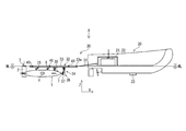
- FIG. 1 is a side sectional view schematically showing a deployment system according to an embodiment of the present invention.
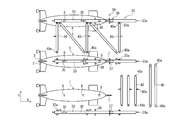
- FIG. 2 is a view taken in the direction of arrow A in FIG.
- FIG. 3 is a plan view schematically showing the support frame, the connecting frame, and the underwater vehicle in the middle of assembly.
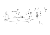
- FIG. 4 is a side view schematically showing a state before the underwater vehicle is mounted on the support frame.
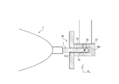
- FIG. 5 is a partially enlarged side view schematically showing a state where the underwater vehicle is mounted on the support frame.
- FIG. 6 is a side sectional view schematically showing the engagement mechanism.
- FIG. 7 is a side sectional view schematically showing another engagement mechanism.
- FIG. 8 is a plan view schematically showing a structure according to another embodiment of the present invention.
- the deployment system of the underwater vehicle 1 uses the tow device 20 towing the deployment device 30 to deploy the underwater vehicle 1.
- This system is towed and deployed to the water area.
- the advancing direction (front-rear direction) of the towing device 20 is the X direction
- the width direction (left-right direction) of the towing device 20 orthogonal to the X direction in the horizontal plane is the Y direction
- the vertical direction (up-down direction) is the Z direction. It is said.
- the underwater vehicle 1 is a device that operates underwater to perform seabed surveying, topographic surveys, etc., and specifically, an autonomous unmanned submarine (AUV), a remotely operated unmanned explorer (ROV), etc. it can.
- the underwater vehicle 1 exemplified in this embodiment has an elongated and substantially elliptical shape as shown in FIGS. 1 and 2, and has a vertical tail 2 and a horizontal tail at the rear.
- a communication device 3 is mounted on the upper part of the vertical tail 2, and a propeller is mounted on each rear part of the horizontal tail.
- An annular member 8 is provided at the upper part of the underwater vehicle 1 at two places (a plurality of places) separated in the front-rear direction. Furthermore, an acoustic device 5 (transponder) is provided on the underwater vehicle 1. At the front end portion of the underwater vehicle 1, an engaged member 7 protrudes in the X direction. Details of the engaged member 7 will be described later.
- the shape and structure of the underwater vehicle 1 and the presence and arrangement of incidental facilities are the configurations of this embodiment. However, the present invention is not limited to this, and various other configurations can be used.
- the deployment device 30 has a structure 32 that is towed in a state where the underwater vehicle 1 is mounted and floated on the water surface, and a connection that connects the structure 32 to the towing device 20. And a mechanism 31.
- the structure 32 includes a support frame 33 that supports the underwater vehicle 1, and the support frame 33 is submerged while part or all of the underwater vehicle 1 is submerged.
- An attachment / detachment mechanism 34 for detachably connecting the body 1 is provided.
- the structure 32 includes three support frames 33 extending in the X direction and spaced apart from each other in the Y direction, and adjacent support frames 33. 6 connecting frames 40 extending in the Y direction and 4 connecting frames 40 arranged on diagonal lines of the frame formed in a lattice shape are provided.
- Each of the support frame 33 and the connection frame 40 is configured to float on an elongated columnar frame having a cavity therein.
- connection frame 33 and the connection frame 40 are provided with connection portions 33a and 40a at a plurality of locations, respectively, and the connection portion 33a of the support frame 33 and the connection portion 40a of the connection frame 40 are detachably joined by a fixture.
- FIG. 3 shows a state in which the two support frames 33 are separated in the upper part of the drawing, and in the lower part of the drawing, the members related to the support frame 33 and the connecting frame 40 are disassembled for each member.
- the attachment / detachment mechanism 34 of this embodiment includes an L-shaped hook 35 that hooks the annular member 8 provided on the upper portion of the underwater vehicle 1, and the front end of the underwater vehicle 1. It is comprised with the engaging mechanism 36 engaged with a part.
- the hook 35 and the engagement mechanism 36 are provided below the support frame 33, respectively.
- the hooks 35 are disposed at two locations in the center of the support frame 33 so as to be separated from each other in the X direction, and an engagement mechanism 36 is disposed further forward than the front L-shaped hook 35.
- a holding member 39 is provided at a position between the front hook 35 and the engagement mechanism 36 in the X direction of the support frame 33.
- the restraining member 39 protrudes downward from the lower portion of the support frame 33.
- the underwater vehicle 1 is disposed below the support frame 33 in a direction in which the propulsion direction is the X direction. Then, the annular member 8 provided in the underwater vehicle 1 is inserted into and hooked on the L-shaped hook 35 provided in the support frame 33, and the front end portion (engaged member) of the underwater vehicle 1 is engaged. 7) and the engagement mechanism 36 (engagement member 37) provided on the support frame 33 are engaged, so that the underwater vehicle 1 is fixed to the support frame 33.
- the front end portion of the underwater vehicle 1 and the engagement mechanism 36 are engaged, the upper front portion of the underwater vehicle 1 is suppressed by the holding member 39, and the holding member 39 moves forward of the underwater vehicle 1. Movement and upward movement are suppressed.
- one set of the attaching / detaching mechanism 34 including the hook 35 and the engaging mechanism 36 and the holding member 39 are provided for one support frame 33, and one support frame 33 is provided with one set.
- the underwater vehicle 1 is configured to be fixed. Further, in a state where the underwater vehicle 1 is mounted on the support frame 33, the vertical tail 2 of the underwater vehicle 1 is disposed behind the rear end portion of the support frame 33 and is provided above the vertical tail 2.
- the communication device 3 is configured to be exposed on the water.
- the support frames 33 are connected to each other by the connecting frame 40 so that the underwater vehicles 1 are separated from each other in a state where the underwater vehicles 1 are mounted.
- the engagement mechanism 36 of this embodiment includes an engagement member 37 that engages with an engaged member 7 provided at the front end of the underwater vehicle 1, and an engaged member 7 and a release member 38 for releasing the engagement between the engagement member 37 and the engagement member 37.
- the release member 38 include a solenoid actuator that moves the pin 38b by energization.
- the engaged member 7 includes a rod-like portion 7a extending in the front-rear direction from the front end portion of the underwater vehicle 1 and a recess 7b provided on the tip side of the rod-like portion 7a. It is configured.
- the engagement member 37 has an engagement hole 37a. The diameter of the engagement hole 37a is set to be larger than the thickness dimension of the rod-like portion 7a of the engaged member 7.
- a pin 38b constituting a release member 38 (solenoid actuator) is provided in the back of the engagement hole 37a.
- the pin 38b When the release member 38 is not energized, the pin 38b protrudes by elastic force such as a spring, and the pin 38b is inserted into the recess 7b so that the recess 7b and the pin 38b are engaged.
- the release member 38 When the release member 38 is energized, the pin 38b is retracted by an electromagnetic force generated by a solenoid coil. As a result, the pin 38b moves outward from the central axis of the rod-like portion 7a, the pin 38b comes out of the recess 7b, the engagement of the pin 38b and the recess 7b is released, and the engaged member 7 and the engaging member The state of engagement with 37 is released.
- the engaged member 7 When the underwater vehicle 1 is attached to the support frame 33, the engaged member 7 is inserted into the engagement hole 37 a of the engagement member 37 in a state where the release member 38 is energized and the pin 38 b is retracted. Insert it all the way. When the energization of the release member 38 is stopped in this state, the pin 38b protrudes and is inserted into the recess 7b by an elastic force such as a spring provided in the release member 38. As a result, the engaged member 7 cannot be pulled out from the engaging hole 37 a of the engaging member 37.
- the engaged member 7 ⁇ / b> A includes a rod-like portion 7 ⁇ / b> Aa extending in the front-rear direction from the front end portion of the underwater vehicle 1, and the rod-like portion 7 ⁇ / b> Aa. It is comprised by projection part 7Ac provided in the front end side.
- the protrusion 7Ac protrudes outward from the rod-shaped portion 7Aa in a state where a certain amount of electromagnetic force is not applied from the outside to the inside toward the central axis of the rod-shaped portion 7Aa, and the protrusion 7Ac is centered on the rod-shaped portion 7Aa.
- the protrusion 7Ac is in a state of being housed inside the rod-like portion 7Aa.
- a release member 38A composed of an electromagnet that generates an electromagnetic force from the outside toward the center axis with respect to the protrusion 7Ac when the current is supplied to the inside of the rod-like portion 7Aa is provided, and the release member 38A is not supplied with electricity.
- the protruding portion 7Ac protrudes from the rod-shaped portion 7Aa, and when the release member 38A is energized, the protruding portion 7Ac is housed inside the rod-shaped portion 7Aa by the electromagnetic force generated by the release member 38A. .
- the engaging member 37A has an engaging hole 37Aa.
- the diameter of the engaging hole 37Aa is larger than the thickness of the rod-like portion 7Aa of the engaged member 7A, and the protruding portion 7Ac protrudes. It is set smaller than the thickness dimension from the central axis of the rod-like portion 7Aa to the tip of the protruding portion 7Ac in the state.
- a groove 37Ab into which the protrusion 7Ac is fitted is provided in the back (front) of the engagement hole 37Aa.
- the release member 38A is inserted.
- the protruding portion 7Ac is fitted into the groove portion 37Ab so that the engaged member 7A cannot be removed from the engaging hole 37Aa.
- the release member 38A is energized, the protrusion 7Ac is housed inside the rod-like part 7Aa, so that the catch between the groove 37Ab and the protrusion 7Ac is released, and the engagement member 37A has an engagement hole 37Aa. The engaged member 7A is pulled out.
- the shape, size, number, arrangement, and the like of the support frame 33 and the connection frame 40 that form the structure 32 are not limited to this embodiment, but depending on the size, number, etc. of the underwater vehicle 1 to be deployed. Various other configurations are possible. Moreover, it is not always necessary to arrange the shapes and sizes of the underwater vehicle 1, the support frame 33, and the connection frame 40. The support frame 33 and the connection frame 40 corresponding to the underwater vehicle 1 to be towed are provided. Use it.
- the support frame 33 and the connection frame 40 are configured by a frame having a cavity therein, but the support frame 33 and the connection frame 40 may be configured by other members.
- the support frame 33 and the connection frame 40 may be formed by combining a plurality of members.
- the structure 32 floats on the water surface by the buoyancy of the support frame 33 and the connecting frame 40 itself.
- the structure 32 can be floated by the buoyancy of the buoyancy material (floating). .
- connection mechanism 31 that connects the structure 32 to the towing device 20 is configured by a rope, a frame, or the like. As illustrated in FIG. 1 and FIG. 2, in this embodiment, the connection mechanism 31 is constituted by a rope, and the towing device is constituted by three ropes extending in the X direction and spaced apart in the Y direction. The rear part of 20 and the front part of the structure 32 are connected. Each of the connecting portion 33a provided on the support frame 33 and the connecting portion 40a provided on the connecting frame 40 is configured to connect the rope, and the end of the rope on the structure 32 side is the support frame 33. The connecting portion 33a and the connecting portion 40a of the connecting frame 40 are respectively connected.
- the towing device 20 includes a ship having a propulsion device and a submersible craft.
- the towing apparatus 20 of this embodiment is composed of an autonomous unmanned navigation ship.
- the towing device 20 is equipped with a communication device 22 capable of wireless communication and a control device 21 connected to the communication device 22 so as to be communicable.
- the communication device 22 is configured to be able to acquire position information (for example, latitude and longitude) from a positioning system such as a global navigation satellite system (GNSS).
- GNSS global navigation satellite system
- An acoustic device 23 capable of acoustic communication with the acoustic device 5 of the underwater vehicle 1 is installed on the bottom of the towing device 20.
- the deployment device 30 is input to the deployment target water area based on the position information acquired by the communication device 22.
- the towing control is autonomously performed.
- the control device 21 is configured such that when the deployment device 30 arrives at the deployment target water area, control for separating the underwater vehicle 1 from the deployment device 30 is autonomously performed in the deployment target water area.
- the structure 32 according to the number of the underwater vehicle 1 to be developed is formed. For example, when it is desired to deploy three underwater vehicles 1, a structure that can be equipped with three underwater vehicles 1 by connecting three support frames 33 and ten connecting frames 40. 32 is formed.
- the underwater vehicle 1 is attached to the structure 32.
- the underwater vehicle 1 is disposed below the support frame 33, and the L-shaped hook 35 provided at the lower part of each support frame 33 is attached to the underwater vehicle 1.
- the annular member 8 provided at the upper portion is hooked.
- the engaged member 7 provided at the front end portion of the underwater vehicle 1 is engaged with an engagement mechanism 36 (engagement member 37) provided at the lower portion of the support frame 33.
- the engaged member 7 is inserted into the engagement hole 37 a provided in the engagement member 37, and then to the release member 38. And the engaged member 7 is engaged with the engaging member 37 by engaging the recess 7b of the engaged member 7 with the pin 38b of the releasing member 38.
- the underwater vehicle 1 is fixed to the support frame 33, and the underwater vehicle 1 is supported by the support frame 33.
- the underwater vehicle 1 is in a state set to a sleep mode in which power consumption is suppressed before being deployed underwater, and is in a state in which power other than the communication device 3 is not used as much as possible.
- the structure 32 with the underwater vehicle 1 mounted thereon is floated on the surface of the water.
- the structure 32 floats on the water surface, and a part or all of the underwater vehicle 1 fixed to the lower part of the structure 32 is submerged.
- the communication device 3 provided on the upper part of the vertical tail 2 of the underwater vehicle 1 is located above the water surface and can communicate, and the other parts of the underwater vehicle 1 are submerged. It will be in the state. This completes the setting before towing.
- the towing device 30 is towed by the towing device 20 to the deployment target water area where the underwater vehicle 1 is deployed.
- position information for example, latitude and longitude
- steering control for towing the deployment apparatus 30 to the deployment target water area is performed by the communication device 22. It is performed autonomously using the position information to be acquired.
- the management unit of the underwater vehicle 1 (the remote area where the manager of the underwater vehicle 1 waits) While towing the middle traveling vehicle 1, the position information of the underwater traveling vehicle 1 can be acquired by communicating with the communication device 3.
- the underwater vehicle 1 is disconnected from the support frame 33 by releasing the connection of the underwater vehicle 1 by the attachment / detachment mechanism 34 in the deployment target water area. Deploy the runner 1 underwater.
- the time at which the underwater vehicle 1 is deployed can be set for each underwater vehicle 1, and the towing device 20 and the deployment device 30 are preliminarily input to the deployment target water area.
- the control device 21 communicates with the communication device 3 of the underwater vehicle 1 via the communication device 22 so that the underwater vehicle 1 set in the sleep mode is displayed.
- Control to switch to the start mode is performed.
- electricity is passed from the towing device 20 or the underwater vehicle 1 to the release member 38, and the recess 7 b of the engaged member 7 and the pin 38 b of the release member 38 are connected.
- the engaged state between the engaged member 7 and the engaging member 37 is released, and the connection between the underwater vehicle 1 and the engaging mechanism 36 is released.
- the towing device 20 moves forward in a state where the connection by the engagement mechanism 36 is released, the underwater vehicle 1 slides rearward relative to the support frame 33, so that an L-shaped hook.
- the annular member 8 of the underwater vehicle 1 is removed from 35, the underwater vehicle 1 is separated from the structure 32 (support frame 33), and the underwater vehicle 1 is deployed in water.
- the deployment work of the underwater vehicle 1 is completed.
- the separated underwater vehicles 1 and the underwater vehicles 1 connected to the separated underwater vehicles 1 are not collided.
- the underwater vehicle 1 is separated from the underwater vehicle 1 arranged on the rear side so that the runners 1 do not collide, and the separated underwater vehicle 1 is separated from the connected underwater vehicle 1 by a sufficient distance. It is preferable to cut off the next underwater vehicle 1 later.
- the towing device 20 stays in the vicinity of the deployment target water area, and the sound of the underwater vehicle 1 is acoustically installed by the acoustic device 23 installed on the bottom of the ship.
- the position information of the underwater vehicle 1 is acquired.
- the acquired position information of the underwater vehicle 1 is transmitted to the management station of the underwater vehicle 1 via the communication device 22 of the towing device 20 so that the management station can detect the position information of the underwater vehicle 1.
- the towing device 20 serves as a relay base that connects the underwater vehicle 1 and the management station.
- the underwater vehicle 1 When the underwater vehicle 1 finishes the activity, the underwater vehicle 1 is collected by a collecting device (not shown) as necessary, and then the towing device 20 tows the deployment device 30 to the recovery target water area inputted in advance. In addition, the deployment device 30 and the towing device 20 are collected in the collection target water area. The underwater vehicle 1 may be collected separately from the towing device 20.
- the structure 32 is floated on the water.
- the structure 32 is floated on the structure 32 in the state where the structure 32 is floated on the water.
- the underwater vehicle 1 can be mounted.
- the underwater vehicle 1 is towed to the deployment target water area together with the structure 32 by the towing device 20 in a state where the underwater vehicle 1 is connected to the support frame 33 via the attachment / detachment mechanism 34.
- the underwater vehicle 1 can be easily deployed in the deployment target water area simply by releasing the connection of the underwater vehicle 1 by the attachment / detachment mechanism 34 in the deployment target water area and disconnecting the underwater vehicle 1 from the support frame 33. .
- the structure 32 floats on the water surface and is towed with the underwater vehicle 1 fixed below the structure 32, the structure 32 and the underwater vehicle 1 interfere with underwater rocks, seaweeds, and the like. Can reduce the risk. Moreover, since the underwater vehicle 1 is towed in a state where part or all of the underwater vehicle 1 is submerged, the underwater vehicle 1 can be quickly and stably stabilized simply by releasing the connection of the underwater vehicle 1 by the attachment / detachment mechanism 34. Can be reliably deployed in water in the state. Furthermore, there is a merit that the underwater vehicle 1 is less likely to receive the impact of the waves during towing by being towed in a state where part or all of the underwater vehicle 1 is submerged.
- the underwater vehicle 1 can be deployed with a simple control of moving the tow device 20 to the deployment target water area and releasing the connection of the underwater vehicle 1 with the attachment / detachment mechanism 34, the steering of the tow device 20 can be performed.
- the control and the control for separating the underwater vehicle 1 from the deployment device 30 can be easily performed by remote operation or autonomous control, and the control of the towing device 20 and the deployment device 30 is remote operation or autonomous control.
- the structure 32 When the structure 32 is formed by connecting the plurality of support frames 33 with the connection frame 40 as in this embodiment, the plurality of support frames 33 are connected with the connection frame 40, so The structure 32 suitable for the number of the bodies 1 can be easily formed flexibly.
- the structure 32 may be formed by connecting the five support frames 33 with the connection frame 40 to form the structure 32 that can deploy the five underwater vehicles 1. it can.
- connection frame 40 by connecting the support frames 33 so that the underwater vehicles 1 are separated from each other by the connection frame 40, the underwater vehicles 1 are separated from each other when towing or separating the underwater vehicle 1 from the deployment device 30. Can be avoided. Furthermore, since the structure 32 is formed by the support frame 33 and the connecting frame 40, the structure 32 having a frame structure with less water resistance and less influence of waves can be formed. It becomes easy to tow the runner 1 in a stable state. Furthermore, as shown in FIG. 2, it is more advantageous to prevent the structural body 32 from being distorted by providing the connecting frame 40 on the diagonal line of the frame formed in a lattice shape.
- the attaching / detaching mechanism 34 is composed of the L-shaped hook 35 and the engaging mechanism 36
- the annular member 8 provided at the upper part of the underwater vehicle 1 is provided with the L-shaped hook 35 provided at the lower part of the support frame 33.
- the underwater vehicle 1 is supported on the support frame 33.
- the annular member 8 is hooked on the L-shaped hook 35
- the underwater vehicle 1 is moved in the front-rear direction, so that the load is not concentrated on the local area of the underwater vehicle 1 and the underwater vehicle 1
- work which engages the front-end part of the body 1 and the engagement mechanism 36 can be performed easily.
- the load of the underwater vehicle 1 is supported by the support frame 33 by the hook 35 and the annular member 8, and the front end portion of the underwater vehicle 1 is fixed to the support frame 33 by the engagement mechanism 36.
- the underwater vehicle 1 can be stably fixed to the support frame 33. In this case, if the buoyancy of the underwater vehicle 1 is the same as the weight, almost no load is applied to the hook 35, the annular member 8, and the support frame 33.
- the connection of the underwater vehicle 1 by the detachable mechanism 34 is released, the engagement of the front end portion of the underwater vehicle 1 by the engagement mechanism 36 is released and the tow device 20 is moved forward, so Since the traveling body 1 can be deployed, the control for separating the underwater traveling body 1 can be greatly simplified.
- the attachment / detachment mechanism 34 can be configured only by the engagement mechanism 36, if the hook 35 is provided, the load applied to the engagement mechanism 36 can be reduced. It is advantageous to reduce.
- an engagement member 37 that engages the engagement mechanism 36 with the engaged member 7 at the front end of the underwater vehicle 1 and a release member that releases the engagement between the engaged member 7 and the engagement member 37. 38, and the engagement state between the engaged member 7 and the engagement member 37 is released by energizing the release member 38, the energization is not applied to the release member 38 during towing.
- the underwater vehicle 1 can be stably fixed to the support frame 33.
- the engagement by the engagement member 37 can be released by the release member 38 by a very simple operation of energizing the release member 38. It is possible to release the connection by the combination mechanism 36 with very simple control. Since the engagement mechanism 36 can be controlled by simple control of whether or not the release member 38 is energized, the risk of malfunction of the engagement mechanism 36 can be reduced.
- the release member 38 on the engagement member 37 side of the support frame 33 is energized, and the pin 38b engaged with the recess 7b at the tip of the underwater vehicle 1 is provided.
- the release member 38 ⁇ / b> A provided inside the engaged member 7 ⁇ / b> A provided in the underwater vehicle 1 is energized, and the underwater vehicle 1 is separated.
- the structure in which the protrusion 7Ac at the tip is retracted and separated by being pulled out from the groove 37Ab is illustrated.
- the position where the release members 38 and 38A are provided and the method of energizing the release members 38 and 38A are described in this embodiment.
- the present invention is not limited to this, and various other configurations can be used.
- the release member 38 may be provided inside the engaged member 7, and the release member 38 may be energized from the towing device 20 via the connection mechanism 31 and the support frame 33.
- the release member 38 may be provided on the engagement member 37 side, and the release member 38 may be energized from the towing device 20 via the connection mechanism 31 and the support frame 33.
- the restraint member 39 is restrained when the underwater vehicle 1 is mounted on the support frame 33. Since the member 39 can suppress the forward movement and the upward movement of the underwater vehicle 1, the underwater vehicle 1 can be more stably fixed to the support frame 33. Further, the provision of the holding member 39 can reduce the load applied to the attachment / detachment mechanism 34 (the engagement mechanism 36 or the L-shaped hook 35), which is advantageous in preventing damage or failure of the attachment / detachment mechanism 34.
- the towing device 20 is configured by an autonomous unmanned navigation ship, and the control device 21 tows the deployment device 30 to the deployment target water area by the communication device 22 and the control device 21 mounted on the towing device 20;
- the control device 21 autonomously performs control for separating the underwater vehicle 1 from the deployment device 30 in the deployment target water area
- the underwater vehicle 1 is mounted on the support frame 33 and the control device for the tow device 20 is provided. Since the underwater vehicle 1 can be automatically deployed to the deployment target water area simply by inputting the location information of the deployment target water area 21, it is possible to efficiently perform seabed surveying and seafloor topography survey with a small number of personnel. It becomes possible.
- the tow apparatus 20 is configured by an autonomous unmanned navigation ship.
- the tow apparatus 20 is an unmanned navigation ship controlled by a remote operation or a manned ship on which a crew is boarded. Can also be configured.
- the tow device 20 is configured by an unmanned navigation ship equipped with a communication device 22 capable of wireless communication and a control device 21 connected to the communication device 22 so as to be communicable.
- the control of the towing device 20 and the control of separating the underwater vehicle 1 from the deployment device 30 can be performed by remote operation via the control device 21.
- the towing device 20 is composed of a manned ship, and the towing device 20 is equipped with a communication device 22 capable of wireless communication and a control device 21 connected to the communication device 22 so as to be communicable.
- the crew member can operate the communication device 22 and the control device 21 to perform the steering control of the towing device 20 and the control of the deployment device 30 and the underwater vehicle 1.
- programming related to the control of the control device 21 can be simplified. Even when the towing device 20 is configured by a manned ship, since the underwater vehicle 1 can be deployed with a small number of people by using the deployment device 30, the towing device 20 is a relatively small ship. Can be configured.
- connection mechanism 32 structure 33 support frame 33a connecting portion 34 attaching / detaching mechanism 35 hook 36, 36A engaging mechanism 37, 37A engaging member 37a, 37Aa engaging hole 37Ab groove 38, 38A release member 38b pin 39 holding member 40 connecting frame 40a Connecting part WL Water surface position
Landscapes
- Engineering & Computer Science (AREA)
- Mechanical Engineering (AREA)
- Ocean & Marine Engineering (AREA)
- Chemical & Material Sciences (AREA)
- Combustion & Propulsion (AREA)
- Transportation (AREA)
- Physics & Mathematics (AREA)
- Acoustics & Sound (AREA)
- Control Of Position, Course, Altitude, Or Attitude Of Moving Bodies (AREA)
Abstract
水面に浮かんだ状態で曳航される構造体32を接続機構31によって曳航装置20に接続した状態とし、構造体32を構成する支持フレーム33に設けられている着脱機構34に水中航走体1を連結することにより、構造体32に水中航走体1を装着し、水中航走体1の一部又は全部を水没させた状態で、構造体32及び水中航走体1を曳航装置20によって水中航走体1の展開目標水域まで曳航し、展開目標水域において着脱機構34による水中航走体1の連結を解除して支持フレーム33から水中航走体1を切り離すことにより、水中航走体1を水中に展開する。これにより、水中航走体を小規模な曳航装置で簡易に展開することができる水中航走体の展開装置、曳航装置、水中航走体の展開システム、及び水中航走体の展開方法を提供する。
Description
本発明は、水中航走体の展開装置、曳航装置、水中航走体の展開システム、及び水中航走体の展開方法に関し、より詳細には、水中航走体を小規模な曳航装置で簡易に展開することができる水中航走体の展開装置、曳航装置、水中航走体の展開システム、及び水中航走体の展開方法に関する。
海底測量や海底の地形調査等を行う水中で活動する装置として、水中航走体が知られている。水中航走体は、オペレーターが遠隔操作する遠隔操作無人探査機(ROV)や、自律型無人潜水機(AUV)等様々な種類を有しており、科学分野や商業分野や軍用分野等で広く利用されている。
従来、水中航走体の水中への展開方法としては、有人の支援母船に水中航走体を収容し、支援母船によって水中航走体を展開する展開目標水域まで航行し、展開目標水域において支援母船に搭載しているクレーンを用いて水中航走体を1台1台水中に投入する方法が一般的である。
このクレーンを用いた水中航走体の展開方法としては、例えば、日本国出願特開2012-229005号公報に記載されているように、水中航走体の長手方向端部を保持して安定させるための保持金具を揚荷手段に支持させる工程と、水中航走体の端部を保持金具に保持させて水中航走体を垂直に吊り上げる工程と、水中航走体を長手方向中心軸に沿った回転軸回りに回動させて着水方向に着水面を向ける工程と、揚荷手段を介して水中航走体を着水する工程とを有することを特徴とする水中航走体の着水揚収方法が提案されている。
しかしながら、このようなクレーンを用いた水中航走体の展開方法では、支援母船にクレーンを設置するスペースと、水中航走体を収容するスペースが必要となる。また、水中航走体にクレーンの吊具(保持金具)を接続する作業や、クレーンを操作して水中航走体を水中に投下させる作業を行うために多くの乗組員(技術者)が必要となる。そのため、従来、水中航走体を利用して海底測量や海底の地形調査等を行う場合には、比較的大きな支援母船と多くの乗組員が必要とされていた。
本発明は、上記の状況を鑑みてなされたものであり、その目的は、水中航走体を小規模な曳航装置で簡易に水中へ展開することができる水中航走体の展開装置、曳航装置、水中航走体の展開システム、及び水中航走体の展開方法を提供することにある。
上記のような目的を達成するための本発明の水中航走体の展開装置は、水中航走体を着脱可能に連結すると共に、曳航装置によって曳航される水中航走体の展開装置であって、前記水中航走体を装着して水面に浮かんだ状態で曳航される構造体と、前記構造体を前記曳航装置に接続する接続機構とを備えると共に、前記構造体が、前記水中航走体を支持する支持フレームを有し、前記支持フレームが前記水中航走体の一部又は全部を水没させた状態で前記水中航走体を着脱可能に連結する着脱機構を有していることを特徴とする。
この水中航走体の展開装置によれば、構造体を構成する支持フレームに着脱機構を介して水中航走体を連結し、曳航装置により構造体とともに水中航走体を展開目標水域まで曳航し、展開目標水域において着脱機構による水中航走体の連結を解除して支持フレームから水中航走体を切り離すだけで、水中航走体を展開目標水域に簡易に展開することができる。
その上、この展開装置では、曳航装置にクレーンを設置するスペースや水中航走体を搭載するスペースを設ける必要がないため、小規模な曳航装置で多くの水中航走体を曳航して展開することが可能となる。
上記の水中航走体の展開装置において、前記構造体が前記支持フレームを複数備えると共に、前記支持フレームに前記水中航走体が装着された状態では、前記水中航走体どうしが互いに離間しているように前記支持フレームどうしが連結フレームによって連結されている構成にすると、複数の支持フレームどうしを連結フレームで連結することで、展開したい水中航走体の台数に合った構造体を臨機応変に簡易に形成することができる。また、支持フレームどうしを連結フレームによって水中航走体どうしが互いに離間するように連結することで、曳航時や展開装置から水中航走体を切り離す際に水中航走体どうしが接触することを回避することができる。
上記の水中航走体の展開装置において、前記着脱機構が前記水中航走体の上部に設けられている環状部材を引っ掛けるL字型のフックと、前記水中航走体の前端部と係合する係合機構とからなり、前記L字型のフック及び前記係合機構がそれぞれ前記支持フレームの下部に設けられている構成にすると次のような効果を発揮できる。
この構成では、水中航走体の上部に設けられている環状部材を支持フレームの下部に設けられたL字型のフックに引っ掛けることで、支持フレームに水中航走体が支持された状態になる。そして、フックに環状部材を引っ掛けた状態で、水中航走体を前後方向に移動させることで、水中航走体の局所に負荷が集中することなく、水中航走体の前端部と係合機構とを係合する作業を容易に行うことができる。
上記の水中航走体の展開装置において、前記係合機構が、前記水中航走体の前端部の被係合部材に係合する係合部材と、前記被係合部材と前記係合部材との係合を解除する解除部材とを有して構成され、前記解除部材への通電がない状態では前記被係合部材と前記係合部材との係合状態が維持されて前記水中航走体が前記支持フレームに支持されたままとなり、前記解除部材に通電があると、前記被係合部材と前記係合部材との係合状態が解除され、前記水中航走体が前記支持フレームから切り離されるように構成にされていると、次のような効果を発揮できる。
この構成では、曳航時には、水中航走体の前端部の被係合部材と係合部材との係合状態を維持することで、水中航走体を支持フレームに対して安定して固定することができる。そして、展開目標水域において係合機構における係合を解除する際には、解除部材に通電するという非常に簡易な操作で解除部材によって係合部材による係合を解除できるので、係合機構による連結の解除を非常に簡易な制御で行うことが可能となる。この解除部材は、例えば、通電によりピンを移動させるようなソレノイドアクチュエータ等で構成することができる。
上記のような目的を達成するための本発明の曳航装置は、上記の水中航走体の展開装置を曳航する曳航装置である。この曳航装置では、上記の展開装置を曳航することで、上記の展開装置と同様の効果を奏することができる。
上記のような目的を達成するための本発明の水中航走体の展開システムは、上記の水中航走体の展開装置と、上記の曳航装置を使用した水中航走体の展開システムであって、前記展開装置の前記支持フレームに前記水中航走体を前記着脱機構により連結して前記水中航走体の一部又は全部を水没させた状態で、前記水中航走体を展開する展開目標水域まで前記展開装置を前記曳航装置により曳航し、前記展開目標水域において前記着脱機構による前記水中航走体の連結を解除して前記支持フレームから前記水中航走体を切り離すことにより、前記水中航走体を水中に展開することを特徴とする。
この水中航走体の展開システムによれば、曳航装置にクレーンを設置するスペースや水中航走体を搭載するスペースを設ける必要がないため、小規模な曳航装置で多くの水中航走体を展開することが可能となる。さらに、構造体が水面に浮かび、その構造体の下方に水中航走体が固定された状態で曳航されるので、構造体や水中航走体が水中の岩や海藻等に干渉するリスクを低減することができる。
上記の水中航走体の展開システムにおいて、前記曳航装置が無人航行船であり、前記曳航装置に、無線通信可能な通信装置と、この通信装置に通信可能に接続された制御装置とが搭載されており、前記通信装置及び前記制御装置を介して、前記曳航装置の操縦制御と、前記展開装置から前記水中航走体を切り離す制御とが遠隔操作で行われる構成にすると、曳航装置に乗組員を搭乗させる必要がなくなるため、水中航走体の展開に要する労力やコストを低減するには有利になる。
上記の水中航走体の展開システムにおいて、前記曳航装置が自律型無人航行船であり、前記曳航装置に搭載されている制御装置に予め前記展開目標水域の位置情報を入力しておくことにより、前記展開装置を前記展開目標水域まで曳航する操縦制御と、前記展開目標水域において前記展開装置から前記水中航走体を切り離す制御とを、前記制御装置が自律的に行うように構成されていると、支持フレームに水中航走体を装着し、曳航装置の制御装置に展開目標水域の位置情報を入力するだけで、水中航走体を自動で展開目標水域に展開することができるので、海底測量や海底の地形調査等を少ない人員で効率的に行うことが可能となる。
上記のような目的を達成するための本発明の水中航走体の展開方法は、上記の水中航走体の展開装置と、上記の曳航装置を使用した水中航走体の展開方法であって、前記水中航走体を前記着脱機構により前記展開装置の前記支持フレームに連結して前記水中航走体の一部又は全部を水没させた状態で、前記展開装置を前記曳航装置により前記水中航走体を展開する展開目標水域まで曳航し、前記展開目標水域において前記着脱機構による前記水中航走体の連結を解除して前記支持フレームから前記水中航走体を切り離すことにより、前記水中航走体を水中に展開することを特徴とする。
この水中航走体の展開方法によれば、曳航装置にクレーンを設置するスペースや水中航走体を搭載するスペースを設ける必要がないため、小規模な曳航装置で多くの水中航走体を展開することが可能となる。さらに、構造体が水面に浮かび、その構造体の下方に水中航走体が固定された状態で曳航されるので、構造体や水中航走体が水中の岩や海藻等に干渉するリスクを低減することができる。
本発明の水中航走体の展開装置、曳航装置、水中航走体の展開システム、及び水中航走体の展開方法によれば、曳航装置にクレーンを設置するスペースや水中航走体を搭載するスペースを設ける必要がないため、小規模な曳航装置で多くの水中航走体を展開することが可能となる。
以下、本発明に係る実施の形態の水中航走体の展開装置、曳航装置、水中航走体の展開システム、及び水中航走体の展開方法を、図面を参照しながら説明する。
図1及び図2に例示するように、本発明に係る実施の形態の水中航走体1の展開システムは、展開装置30を曳航する曳航装置20を使用して水中航走体1を展開目標水域まで曳航して展開するシステムである。図中では、曳航装置20の進行方向(前後方向)をX方向とし、X方向と水平面において直交する曳航装置20の幅方向(左右方向)をY方向とし、鉛直方向(上下方向)をZ方向としている。
水中航走体1は、海底測量や海底の地形調査等を行う水中で活動する装置であり、具体的には、自律型無人潜水機(AUV)や遠隔操作無人探査機(ROV)などが例示できる。この実施の形態で例示する水中航走体1は、図1や図2等に示すように、細長の略楕円体形状であり、後部に垂直尾翼2と、水平尾翼を有している。垂直尾翼2の上部には、通信機器3が搭載されており、水平尾翼の後部にはそれぞれ推進器が装備されている。
この水中航走体1の上部には、前後方向に離間した2ヶ所(複数の場所)にそれぞれ環状部材8が設けられている。さらに、水中航走体1の上部には音響機器5(トランスポンダ)が設けられている。水中航走体1の前端部には、被係合部材7がX方向に突設されている。この被係合部材7の詳細については後述する。なお、水中航走体1の形状や構造、付帯設備(推進器や、通信機器3、環状部材8、音響機器5、被係合部材7等)の有無及び配置等はこの実施の形態の構成に限定されず、他にも様々な構成にすることができる。
展開装置30は、図1や図2等に示すように、水中航走体1を装着して水面に浮かんだ状態で曳航される構造体32と、構造体32を曳航装置20に接続する接続機構31とを備えている。構造体32は、水中航走体1を支持する支持フレーム33を有して構成されていて、支持フレーム33には、水中航走体1の一部又は全部を水没させた状態で水中航走体1を着脱可能に連結する着脱機構34が設けられている。
図2及び図3に例示するように、この実施の形態の構造体32は、Y方向に離間して配置されたX方向に延在する3本の支持フレーム33と、隣り合う支持フレーム33どうしを連結するY方向に延在する6本の連結フレーム40と、格子状に形成されたフレームの対角線上に配置された4本の連結フレーム40が設けられている。支持フレーム33及び連結フレーム40はそれぞれ、内部に空洞が設けられた細長の円柱形状のフレームで浮上するように構成されている。
支持フレーム33及び連結フレーム40にはそれぞれ複数箇所に連結部33a、40aが設けられていて、支持フレーム33の連結部33aと連結フレーム40の連結部40aとが固定具によって着脱可能に接合されている。図3では、紙面上方では、2つの支持フレーム33が分離している状態を示し、紙面下方では、支持フレーム33と連結フレーム40に関連する部材を分解して部材ごとに示している。
図4に例示するように、この実施の形態の着脱機構34は、水中航走体1の上部に設けられている環状部材8を引っ掛けるL字型のフック35と、水中航走体1の前端部と係合する係合機構36とで構成されている。フック35及び係合機構36はそれぞれ支持フレーム33の下部に設けられている。フック35は支持フレーム33の中央にX方向に離間して2か所に配置されていて、前方のL字型のフック35よりもさらに前方に係合機構36が配置されている。さらに、この実施の形態では、支持フレーム33のX方向における前側のフック35と係合機構36との間の位置に、抑え部材39が設けられている。抑え部材39は、支持フレーム33の下部から下方に突設されている。
図5に例示するように、水中航走体1は、推進方向がX方向となる向きで支持フレーム33の下方に配置される。そして、支持フレーム33に設けられているL字型のフック35に水中航走体1に設けられている環状部材8を挿通させて引っ掛けるとともに、水中航走体1の前端部(被係合部材7)と支持フレーム33に設けられた係合機構36(係合部材37)とを係合することで、支持フレーム33に対して水中航走体1が固定された状態となる。水中航走体1の前端部と係合機構36とを係合すると、抑え部材39によって水中航走体1の前方上部が抑えられた状態となり、抑え部材39によって水中航走体1の前方への移動と上方への移動が抑止された状態になる。
この実施の形態では、1つの支持フレーム33に対してフック35及び係合機構36からなる着脱機構34と抑え部材39が1組ずつ設けられていて、1つの支持フレーム33に対して1台の水中航走体1が固定される構成になっている。また、支持フレーム33に水中航走体1が装着された状態で、水中航走体1の垂直尾翼2が支持フレーム33の後端部よりも後方に配置され、垂直尾翼2の上部に設けられた通信機器3が水上に露出した状態となるように構成されている。支持フレーム33どうしは連結フレーム40によって、水中航走体1が装着された状態で、水中航走体1どうしが互いに離間しているように連結されている。
図6に例示するように、この実施の形態の係合機構36は、水中航走体1の前端部に設けられた被係合部材7に係合する係合部材37と、被係合部材7と係合部材37との係合を解除する解除部材38とを有して構成されている。この解除部材38としては、通電によりピン38bを移動させるようなソレノイドアクチュエータ等が例示できる。被係合部材7と係合機構36とを係合すると、解除部材38への通電がない状態では被係合部材7と係合部材37との係合状態が維持されて水中航走体1が支持フレーム33に支持された状態が維持される。そして、解除部材38に通電があると、被係合部材7と係合部材37との係合状態が解除され、水中航走体1が支持フレーム33から切り離される構成になっている。
例えば、図6に示すように、被係合部材7は、水中航走体1の前端部から前後方向に延在する棒状部7aと、棒状部7aの先端側に設けられた凹部7bとで構成されている。一方、係合部材37は係合穴37aを有している。係合穴37aの穴径は、被係合部材7の棒状部7aの太さ寸法よりも大きく設定されている。そして、係合穴37aの奥に解除部材38(ソレノイドアクチュエータ)を構成するピン38bが設けられている。
この解除部材38は通電されていない状態では、バネなどの弾性力によりピン38bを突出し、このピン38bが凹部7bに挿入されて、凹部7bとピン38bとが係合している状態となる。そして、この解除部材38は、通電されると、ソレノイドコイルが発生する電磁力などによりピン38bを引込める。これにより、ピン38bが棒状部7aの中心軸から外側に移動して、このピン38bが凹部7bから出て、ピン38bと凹部7bの係合が外れて、被係合部材7と係合部材37との係合状態が解除される。
そして、水中航走体1を支持フレーム33に装着する場合は、解除部材38に通電しピン38bが引込められている状態で、係合部材37の係合穴37aに被係合部材7を奥まで挿入する。この状態で、解除部材38への通電を止めると、解除部材38に備わっているバネなどの弾性力により、ピン38bが突出して、凹部7bに挿入される。これにより、係合部材37の係合穴37aから被係合部材7が引き抜けない状態となる。
一方、水中航走体1を支持フレーム33から分離する場合は、解除部材38に通電すると、電磁力によりピン38bが引き込まれて凹部7bから外れる。これにより、ピン38bと凹部7bとの係合が解除され、係合部材37の係合穴37aから被係合部材7が引き抜ける状態となる。
また、図7に示すように、別の係合機構36Aの例として、被係合部材7Aは、水中航走体1の前端部から前後方向に延在する棒状部7Aaと、棒状部7Aaの先端側に設けられた突起部7Acとで構成されている。
この突起部7Acは、棒状部7Aaの中心軸に向って外側から内側に一定以上の電磁力が加わらない状態では棒状部7Aaよりも外側に突出した状態となり、突起部7Acに棒状部7Aaの中心軸に向って外側から内側に一定以上の電磁力が加わると、突起部7Acが棒状部7Aaの内部に収納される状態となる構造になっている。
棒状部7Aaの内部には通電すると突起部7Acに対して中心軸に向って外側から内側に電磁力を発生させる電磁石で構成された解除部材38Aが設けられていて、解除部材38Aに通電がない状態では突起部7Acが棒状部7Aaから突出した状態となり、解除部材38Aに通電があると解除部材38Aが発生させる電磁力によって突起部7Acが棒状部7Aaの内部に収納される構成になっている。
係合部材37Aは係合穴37Aaを有していて、その係合穴37Aaの穴径は、被係合部材7Aの棒状部7Aaの太さ寸法よりも大きく、かつ、突起部7Acが突出した状態における棒状部7Aaの中心軸から突起部7Acの先端までの太さ寸法よりも小さく設定されている。
係合穴37Aaの奥(前部)には、突起部7Acが嵌る溝部37Abが設けられていて、係合部材37Aの係合穴37Aaに被係合部材7Aを奥まで挿入すると、解除部材38Aに通電がない状態では突起部7Acが溝部37Abに嵌ることで係合穴37Aaから被係合部材7Aが抜けない状態となる。一方、解除部材38Aに通電があると、突起部7Acが棒状部7Aaの内部に収納されることで、溝部37Abと突起部7Acとの引っ掛かりが解除され、係合部材37Aの係合穴37Aaから被係合部材7Aが引き抜ける状態となる。
なお、構造体32を形成する支持フレーム33及び連結フレーム40の形状やサイズ、本数、配置等は、この実施の形態に限定されず、展開する水中航走体1のサイズや台数等に応じて他にも様々な構成にすることができる。また、必ずしも、水中航走体1、支持フレーム33及び連結フレーム40の形状やサイズを揃える必要はなく、曳航する水中航走体1に合わせて、それぞれに対応する支持フレーム33及び連結フレーム40を用いればよい。
この実施の形態では、支持フレーム33及び連結フレーム40を内部に空洞が設けられたフレームで構成しているが、支持フレーム33及び連結フレーム40は他の部材で構成することもできる。支持フレーム33及び連結フレーム40は複数の部材を組み合わせて形成することもできる。また、この実施の形態では、支持フレーム33及び連結フレーム40自身の浮力によって構造体32が水面に浮かぶ構成としているが、構造体32を浮力材(浮き)の浮力によって浮かせる構成にすることもできる。
構造体32を曳航装置20に接続する接続機構31は、ロープやフレーム等で構成される。図1及び図2に例示するように、この実施の形態では接続機構31がロープで構成されており、Y方向に離間して配置されたX方向に延在する3本のロープによって、曳航装置20の後部と構造体32の前部とが接続されている。支持フレーム33に設けられている連結部33aと連結フレーム40に設けられている連結部40aはそれぞれ、ロープを連結できる構成になっており、ロープの構造体32側の端部は、支持フレーム33の連結部33aと連結フレーム40の連結部40aにそれぞれ連結されている。
曳航装置20は推進装置を有する船舶や潜水艇で構成される。この実施の形態の曳航装置20は自律型無人航行船で構成されている。曳航装置20には無線通信可能な通信装置22と、この通信装置22に通信可能に接続された制御装置21が搭載されている。通信装置22は、全地球航法衛星システム(GNSS)等の測位システムから位置情報(例えば、緯度経度)を取得できる構成となっている。曳航装置20の船底などには、水中航走体1の音響機器5と音響通信可能な音響装置23が設置されている。
この曳航装置20では、制御装置21に水中航走体1を展開する展開目標水域の位置情報を入力すると、通信装置22によって取得した位置情報に基づいて、展開装置30を入力した展開目標水域まで曳航する操縦制御が自律的に行われる構成になっている。さらに、この制御装置21は展開装置30が展開目標水域に到着すると、展開目標水域において展開装置30から水中航走体1を切り離す制御が自律的に行われる構成になっている。
次に、この展開システムによって水中航走体1を水中へ展開する方法を以下に説明する。
まず、展開する水中航走体1の台数に合わせた構造体32を形成する。例えば、3台の水中航走体1を展開したい場合には、3本の支持フレーム33と10本の連結フレーム40を連結することで、3台の水中航走体1を装着可能な構造体32を形成する。
次いで、構造体32に水中航走体1を装着する。この実施の形態では、まず、支持フレーム33の下方に水中航走体1を配置して、それぞれの支持フレーム33の下部に設けられているL字型のフック35に、水中航走体1の上部に設けられている環状部材8を引っ掛けた状態にする。そして、水中航走体1の前端部に設けられている被係合部材7を、支持フレーム33の下部に設けられている係合機構36(係合部材37)に係合する。
具体的には、解除部材38に通電してピン38bを引込めた状態で、係合部材37に設けられている係合穴37aに被係合部材7を挿入し、その後、解除部材38への通電をやめて被係合部材7の凹部7bと解除部材38のピン38bを係合させることで、被係合部材7と係合部材37とを係合した状態にする。以上により、支持フレーム33に水中航走体1が固定され、水中航走体1が支持フレーム33に支持された状態となる。水中航走体1は、水中に展開する前の段階では、電力消費を抑えたスリープモードに設定された状態となっていて通信機器3以外には極力電力を使用しない状態となっている。
次いで、接続機構31により曳航装置20に対して構造体32を接続した状態で、水中航走体1が装着された状態の構造体32を水面に浮かべる。すると、構造体32は水面に浮かんだ状態となり、構造体32の下部に固定されている水中航走体1の一部又は全部が水没した状態となる。この実施の形態では、水中航走体1の垂直尾翼2の上部に設けられた通信機器3は水面よりも上側に位置して通信可能な状態となり、水中航走体1のその他の部分は水没した状態となる。以上により、曳航前のセッティングが完了する。
次いで、水中航走体1を展開する展開目標水域まで、曳航装置20によって展開装置30を曳航する。この実施の形態では、曳航装置20の制御装置21に展開目標水域の位置情報(例えば、緯度経度)を入力することで、展開装置30を展開目標水域まで曳航する操舵制御が、通信装置22が取得する位置情報を利用して自律的に行われる。
水中航走体1は通信機器3が通信可能な状態で曳航されるので、水中航走体1の管理部(水中航走体1の管理者が待機する遠隔地)は、曳航装置20が水中航走体1を曳航している間、通信機器3と通信することで、水中航走体1の位置情報等を取得することができる。
そして、曳航装置20が展開目標水域に到着した後、展開目標水域において着脱機構34による水中航走体1の連結を解除して、支持フレーム33から水中航走体1を切り離すことにより、水中航走体1を水中に展開する。
この実施の形態の制御装置21では、水中航走体1を展開する時刻を水中航走体1毎に設定できるようになっていて、曳航装置20及び展開装置30が予め入力された展開目標水域に到着し、設定された時刻になると、制御装置21により、通信装置22を介して水中航走体1の通信機器3と通信することで、スリープモードに設定されていた水中航走体1を発進モードに切り替える制御が行われる。そして、水中航走体1が発進モードに切り替わると、曳航装置20又は水中航走体1から解除部材38に電気が流され、被係合部材7の凹部7bと解除部材38のピン38bとの係合が解除されることによって被係合部材7と係合部材37との係合状態が解除され、水中航走体1と係合機構36との連結が解除される構成となっている。
そして、係合機構36による連結が解除された状態で、曳航装置20が前進すると、支持フレーム33に対して水中航走体1が相対的に後方にスライド移動することで、L字型のフック35から水中航走体1の環状部材8が外れて、水中航走体1が構造体32(支持フレーム33)から切り離された状態となり、水中航走体1が水中に展開される。以上により、水中航走体1の展開作業が完了する。
なお、複数の水中航走体1を曳航している場合には、分離された水中航走体1と連結されている水中航走体1とが衝突しないように、また、分離された水中航走体1どうしが衝突しないように、後ろ側に配置された水中航走体1から切り離し、この分離された水中航走体1が、連結されている水中航走体1と十分な距離離れた後に、次の水中航走体1を切り離すことが好ましい。
この実施の形態では、水中航走体1を展開目標水域に展開した後には、曳航装置20は展開目標水域の近傍に留まり、船底などに設置された音響装置23で水中航走体1の音響機器5と通信することにより、水中航走体1の位置情報を取得する。そして、その取得した水中航走体1の位置情報を、曳航装置20の通信装置22を介して水中航走体1の管理局に送信することで、管理局が水中航走体1の位置情報を把握できるようになっている。即ち、水中航走体1を展開した後、曳航装置20は、水中航走体1と管理局を繋ぐ中継基地の役割をする。
そして、水中航走体1が活動を終えると、必要に応じて図示しない回収装置で水中航走体1を回収してから、曳航装置20はあらかじめ入力された回収目標水域まで展開装置30を曳航し、回収目標水域において展開装置30及び曳航装置20が回収される構成となっている。なお、水中航走体1の回収はこの曳航装置20とは別に行ってもよい。
なお、上記で例示した作業手順では、構造体32に対して水中航走体1を装着した後に、構造体32を水上に浮かべたが、構造体32を水上に浮かべた状態で構造体32に対して水中航走体1を装着することもできる。
このように、本発明では、支持フレーム33に着脱機構34を介して水中航走体1を連結した状態で、曳航装置20により構造体32とともに水中航走体1を展開目標水域まで曳航し、展開目標水域において着脱機構34による水中航走体1の連結を解除して支持フレーム33から水中航走体1を切り離すだけで、水中航走体1を展開目標水域に簡易に展開することができる。
この構造体32は水面に浮かび、その構造体32の下方に水中航走体1が固定された状態で曳航されるので、構造体32や水中航走体1が水中の岩や海藻等に干渉するリスクを低減することができる。また、水中航走体1は、一部又は全部が水没した状態で曳航されるので、着脱機構34による水中航走体1の連結を解除するだけで、水中航走体1を速やかに安定した状態で確実に水中に展開することができる。さらに、水中航走体1の一部又は全部が水没した状態で曳航されることで、曳航時に水中航走体1が波による衝撃を受け難くなるというメリットもある。
その上、曳航装置20にクレーンを設置するスペースや水中航走体1を搭載するスペースを設ける必要がないため、小規模な曳航装置20で多くの水中航走体1を曳航して展開することが可能となる。さらに、曳航装置20を展開目標水域まで移動させて、着脱機構34による水中航走体1連結を解除するという簡易な制御で水中航走体1を展開することができるので、曳航装置20の操舵制御と、展開装置30から水中航走体1を切り離す制御とを、遠隔操作又は自律制御にすることが容易に可能であり、曳航装置20及び展開装置30の制御を遠隔操作又は自律制御とすることで、無人の曳航装置20及び展開装置30で水中航走体1を展開することも可能となる。
この実施の形態のように、複数の支持フレーム33どうしを連結フレーム40によって連結して構造体32を形成すると、複数の支持フレーム33どうしを連結フレーム40で連結することで、展開したい水中航走体1の台数に合った構造体32を臨機応変に簡易に形成することができる。例えば、図8に例示するように、構造体32を5本の支持フレーム33を連結フレーム40で連結することで、5台の水中航走体1を展開可能な構造体32を形成することもできる。
また、支持フレーム33どうしを連結フレーム40によって水中航走体1どうしが互いに離間するように連結することで、曳航時や展開装置30から水中航走体1を切り離す際に水中航走体1どうしが接触することを回避することができる。さらに、構造体32を支持フレーム33及び連結フレーム40で形成することで、水の抵抗が少なく波の影響も少ないフレーム構造の構造体32を形成できるので、曳航装置20によって構造体32及び水中航走体1を安定した状態で曳航し易くなる。さらに、図2に示すように、格子状に形成されたフレームの対角線上に連結フレーム40を設けると、構造体32が歪むことを防止するにはより有利になる。
着脱機構34をL字型のフック35及び係合機構36で構成すると、水中航走体1の上部に設けられている環状部材8を支持フレーム33の下部に設けられたL字型のフック35に引っ掛けることで、支持フレーム33に水中航走体1が支持された状態になる。そして、L字型のフック35に環状部材8を引っ掛けた状態で、水中航走体1を前後方向に移動させることで、水中航走体1の局所に負荷が集中することなく、水中航走体1の前端部と係合機構36とを係合する作業を容易に行うことができる。
さらに、曳航時には、フック35及び環状部材8によって水中航走体1の荷重を支持フレーム33で支持するとともに、係合機構36によって支持フレーム33に対して水中航走体1の前端部を固定することで、支持フレーム33に対して水中航走体1を安定して固定することができる。なお、この場合に、水中航走体1の浮力を重量と同じにしておくと、フック35、環状部材8及び支持フレーム33に荷重が殆んど掛らなくなる。
着脱機構34による水中航走体1の連結を解除する際には、係合機構36による水中航走体1の前端部の係合を解除して、曳航装置20を前進させるだけで、水中航走体1を展開することができるので、水中航走体1を切り離す制御も非常に簡易にすることができる。着脱機構34を係合機構36のみで構成することもできるが、フック35を有して構成すると、係合機構36にかかる負荷を低減することができるので、係合機構36が故障するリスクを低減するには有利になる。
さらに、係合機構36を水中航走体1の前端部の被係合部材7に係合する係合部材37と、被係合部材7と係合部材37との係合を解除する解除部材38とを有して構成し、被係合部材7と係合部材37との係合状態が解除部材38に通電することによって解除される構成にすると、曳航時には、解除部材38に通電せずに、被係合部材7と係合部材37との係合状態を維持することで、水中航走体1を支持フレーム33に対して安定して固定することができる。
そして、展開目標水域において係合機構36における係合を解除する際には、解除部材38に通電するという非常に簡易な操作で解除部材38により係合部材37による係合を解除できるで、係合機構36による連結の解除を非常に簡易な制御で行うことが可能となる。解除部材38に通電するか否かの簡易な制御で係合機構36を制御できるので、係合機構36の作動不良が起こるリスクも低くできる。
なお、この実施の形態では、図6に示すような、支持フレーム33の係合部材37側の解除部材38に通電して、水中航走体1の先端の凹部7bに係合するピン38bを引込ませることで分離する構成と、図7に示すような、水中航走体1に設けられた被係合部材7Aの内部に設けられた解除部材38Aに通電して、水中航走体1の先端の突起部7Acを引込めて、溝部37Abから抜けることで分離する構成を例示しているが、解除部材38、38Aを設ける位置や解除部材38、38Aに通電する方法は、この実施の形態に限定されず他にも様々な構成にすることができる。
例えば、被係合部材7の内部に解除部材38を設け、曳航装置20から接続機構31及び支持フレーム33を介して解除部材38に通電する構成にすることもできる。また、例えば、解除部材38を係合部材37側に設け、曳航装置20から接続機構31及び支持フレーム33を介して解除部材38に通電する構成にすることもできる。
この実施の形態のように、支持フレーム33の下部に水中航走体1の前方上部を抑える抑え部材39を設けた構成にすると、支持フレーム33に水中航走体1を装着した際に、抑え部材39によって水中航走体1の前方への移動と上方への移動を抑えることができるので、支持フレーム33に対して水中航走体1をより安定して固定することができる。また、抑え部材39を設けることで、着脱機構34(係合機構36やL字型のフック35)にかかる負荷を低減できるので、着脱機構34の損傷や故障を防ぐのには有利になる。
この実施の形態のように、曳航装置20を自律型無人航行船で構成し、曳航装置20に搭載した通信装置22及び制御装置21により、展開装置30を展開目標水域まで曳航する操縦制御と、展開目標水域において展開装置30から水中航走体1を切り離す制御とを、制御装置21が自律的に行う構成にすると、支持フレーム33に水中航走体1を装着し、曳航装置20の制御装置21に展開目標水域の位置情報を入力するだけで、水中航走体1を展開目標水域に自動的に展開することができるので、海底測量や海底の地形調査等を少ない人員で効率的に行うことが可能となる。
従来では、海底測量や海底の地形調査等を行う際に、支援母船や乗組員(技術者)のスケジュールを抑える必要があったが、この構成では、水中航走体1の展開を自動的に行えるので、海底測量や海底の地形調査等をより行い易くなる。さらに、曳航装置20に乗組員が搭乗するスペースを設ける必要がないため、曳航装置20を小規模で簡素な構成にすることができる。また、曳航装置20に乗組員が搭乗する必要がないため、人が立ち入ることが難しい水域においても水中航走体1を展開することが可能となる。
なお、上記で例示した実施の形態では、曳航装置20を自律型無人航行船で構成する場合を例示したが、曳航装置20は遠隔操作で制御する無人航行船や、乗組員が搭乗する有人船で構成することもできる。
具体的には、例えば、曳航装置20を、無線通信可能な通信装置22と、この通信装置22に通信可能に接続された制御装置21とが搭載された無人航行船で構成し、通信装置22及び制御装置21を介して、曳航装置20の操縦制御と、展開装置30から水中航走体1を切り離す制御とを遠隔操作で行う構成にすることもできる。この構成にすると、曳航装置20に乗組員を搭乗させる必要がなくなるため、水中航走体1の展開に要する労力やコストを低減するには有利になる。また、曳航装置20に乗組員が搭乗する必要がないため、人が立ち入ることが難しい水域においても水中航走体1を展開することが可能となる。
曳航装置20を有人船で構成し、曳航装置20に、無線通信可能な通信装置22と、この通信装置22に通信可能に接続された制御装置21が搭載されており、曳航装置20に搭乗する乗組員が通信装置22及び制御装置21を操作して、曳航装置20の操舵制御と展開装置30及び水中航走体1の制御を行なう構成にすることもできる。この構成にすると、制御装置21の制御に関するプログラミングを簡素化できるというメリットがある。なお、曳航装置20を有人船で構成する場合にも、展開装置30を使用することで、少ない人員で水中航走体1を展開させることができるので、曳航装置20は比較的小規模な船舶で構成することができる。
1 水中航走体
2 垂直尾翼
3 通信機器
4 制御機器
5 音響機器
7 被係合部材
7a、7Aa 棒状部
7Ac 突起部
7b 凹部
8 環状部材
20 曳航装置
21 制御装置
22 通信装置
23 音響装置
30 展開装置
31 接続機構
32 構造体
33 支持フレーム
33a 連結部
34 着脱機構
35 フック
36、36A 係合機構
37、37A 係合部材
37a、37Aa 係合穴
37Ab 溝部
38、38A 解除部材
38b ピン
39 抑え部材
40 連結フレーム
40a 連結部
WL 水面位置
2 垂直尾翼
3 通信機器
4 制御機器
5 音響機器
7 被係合部材
7a、7Aa 棒状部
7Ac 突起部
7b 凹部
8 環状部材
20 曳航装置
21 制御装置
22 通信装置
23 音響装置
30 展開装置
31 接続機構
32 構造体
33 支持フレーム
33a 連結部
34 着脱機構
35 フック
36、36A 係合機構
37、37A 係合部材
37a、37Aa 係合穴
37Ab 溝部
38、38A 解除部材
38b ピン
39 抑え部材
40 連結フレーム
40a 連結部
WL 水面位置
Claims (9)
- 水中航走体を着脱可能に連結すると共に、曳航装置によって曳航される水中航走体の展開装置であって、
前記水中航走体を装着して水面に浮かんだ状態で曳航される構造体と、前記構造体を前記曳航装置に接続する接続機構とを備えると共に、
前記構造体が、前記水中航走体を支持する支持フレームを有し、前記支持フレームが前記水中航走体の一部又は全部を水没させた状態で前記水中航走体を着脱可能に連結する着脱機構を有していることを特徴とする水中航走体の展開装置。 - 前記構造体が前記支持フレームを複数備えると共に、前記支持フレームに前記水中航走体が装着された状態では、前記水中航走体どうしが互いに離間しているように前記支持フレームどうしが連結フレームによって連結されている請求項1に記載の水中航走体の展開装置。
- 前記着脱機構が、前記水中航走体の上部に設けられている環状部材を引っ掛けるL字型のフックと、前記水中航走体の前端部と係合する係合機構とからなり、前記L字型のフック及び前記係合機構がそれぞれ前記支持フレームの下部に設けられている請求項1又は2に記載の水中航走体の展開装置。
- 前記係合機構が、前記水中航走体の前端部の被係合部材に係合する係合部材と、前記被係合部材と前記係合部材との係合を解除する解除部材とを有して構成され、前記解除部材への通電がない状態では前記被係合部材と前記係合部材との係合状態が維持されて前記水中航走体が前記支持フレームに支持されたままとなり、前記解除部材に通電があると、前記被係合部材と前記係合部材との係合状態が解除され、前記水中航走体が前記支持フレームから切り離されるように構成されている請求項3に記載の水中航走体の展開装置。
- 請求項1~4のいずれか1項に記載の水中航走体の展開装置を曳航する曳航装置。
- 請求項1~4のいずれか1項に記載の水中航走体の展開装置と、請求項5に記載の曳航装置を使用した水中航走体の展開システムであって、前記展開装置の前記支持フレームに前記水中航走体を前記着脱機構により連結して前記水中航走体の一部又は全部を水没させた状態で、前記水中航走体を展開する展開目標水域まで前記展開装置を前記曳航装置により曳航し、前記展開目標水域において前記着脱機構による前記水中航走体の連結を解除して前記支持フレームから前記水中航走体を切り離すことにより、前記水中航走体を水中に展開することを特徴とする水中航走体の展開システム。
- 前記曳航装置が無人航行船であり、前記曳航装置に、無線通信可能な通信装置と、この通信装置に通信可能に接続された制御装置とが搭載されており、前記通信装置及び前記制御装置を介して、前記曳航装置の操縦制御と、前記展開装置から前記水中航走体を切り離す制御とが遠隔操作で行われる請求項6に記載の水中航走体の展開システム。
- 前記曳航装置が自律型無人航行船であり、前記曳航装置に搭載されている制御装置に予め前記展開目標水域の位置情報を入力しておくことにより、前記展開装置を前記展開目標水域まで曳航する操縦制御と、前記展開目標水域において前記展開装置から前記水中航走体を切り離す制御とを、前記制御装置が自律的に行うように構成されている請求項6に記載の水中航走体の展開システム。
- 請求項1~4のいずれか1項に記載の水中航走体の展開装置と、請求項5に記載の曳航装置を使用した水中航走体の展開方法であって、前記水中航走体を前記着脱機構により前記展開装置の前記支持フレームに連結して前記水中航走体の一部又は全部を水没させた状態で、前記展開装置を前記曳航装置により前記水中航走体を展開する展開目標水域まで曳航し、前記展開目標水域において前記着脱機構による前記水中航走体の連結を解除して前記支持フレームから前記水中航走体を切り離すことにより、前記水中航走体を水中に展開することを特徴とする水中航走体の展開方法。
Applications Claiming Priority (2)
| Application Number | Priority Date | Filing Date | Title |
|---|---|---|---|
| JP2018-052104 | 2018-03-20 | ||
| JP2018052104A JP6912409B2 (ja) | 2018-03-20 | 2018-03-20 | 水中航走体の展開装置、曳航装置、水中航走体の展開システム、及び水中航走体の展開方法 |
Publications (1)
| Publication Number | Publication Date |
|---|---|
| WO2019181739A1 true WO2019181739A1 (ja) | 2019-09-26 |
Family
ID=67987222
Family Applications (1)
| Application Number | Title | Priority Date | Filing Date |
|---|---|---|---|
| PCT/JP2019/010609 Ceased WO2019181739A1 (ja) | 2018-03-20 | 2019-03-14 | 水中航走体の展開装置、曳航装置、水中航走体の展開システム、及び水中航走体の展開方法 |
Country Status (2)
| Country | Link |
|---|---|
| JP (1) | JP6912409B2 (ja) |
| WO (1) | WO2019181739A1 (ja) |
Cited By (1)
| Publication number | Priority date | Publication date | Assignee | Title |
|---|---|---|---|---|
| CN115535170A (zh) * | 2022-10-24 | 2022-12-30 | 中国舰船研究设计中心 | 一种用于航行体上浮试验的水下拖曳装置 |
Families Citing this family (4)
| Publication number | Priority date | Publication date | Assignee | Title |
|---|---|---|---|---|
| JP7080868B2 (ja) * | 2019-10-17 | 2022-06-06 | 三菱重工業株式会社 | 水中航走体 |
| JP7638108B2 (ja) * | 2021-02-22 | 2025-03-03 | 三菱重工業株式会社 | 航走体投入装置 |
| KR102576923B1 (ko) * | 2023-02-10 | 2023-09-11 | 마린리서치(주) | 해양조사 및 수심측량을 위한 유무인 복합 수상 조사이동체 |
| JP2024118954A (ja) * | 2023-02-21 | 2024-09-02 | 株式会社ドローンステーション | 無人海中探査システム、管理装置、無人海中探査システムの制御方法 |
Citations (3)
| Publication number | Priority date | Publication date | Assignee | Title |
|---|---|---|---|---|
| US3448712A (en) * | 1968-01-30 | 1969-06-10 | Gen Dynamics Corp | Buoyant floats for docking and towing seacraft |
| US6840188B1 (en) * | 2003-06-25 | 2005-01-11 | Columbia Research Corporation | Towed transport, launch and recovery raft |
| WO2009002520A2 (en) * | 2007-06-26 | 2008-12-31 | Talmor Amnon G | Shallow water wet-dry vehicle and a littoral fighting vehicle |
-
2018
- 2018-03-20 JP JP2018052104A patent/JP6912409B2/ja active Active
-
2019
- 2019-03-14 WO PCT/JP2019/010609 patent/WO2019181739A1/ja not_active Ceased
Patent Citations (3)
| Publication number | Priority date | Publication date | Assignee | Title |
|---|---|---|---|---|
| US3448712A (en) * | 1968-01-30 | 1969-06-10 | Gen Dynamics Corp | Buoyant floats for docking and towing seacraft |
| US6840188B1 (en) * | 2003-06-25 | 2005-01-11 | Columbia Research Corporation | Towed transport, launch and recovery raft |
| WO2009002520A2 (en) * | 2007-06-26 | 2008-12-31 | Talmor Amnon G | Shallow water wet-dry vehicle and a littoral fighting vehicle |
Cited By (1)
| Publication number | Priority date | Publication date | Assignee | Title |
|---|---|---|---|---|
| CN115535170A (zh) * | 2022-10-24 | 2022-12-30 | 中国舰船研究设计中心 | 一种用于航行体上浮试验的水下拖曳装置 |
Also Published As
| Publication number | Publication date |
|---|---|
| JP6912409B2 (ja) | 2021-08-04 |
| JP2019162946A (ja) | 2019-09-26 |
Similar Documents
| Publication | Publication Date | Title |
|---|---|---|
| WO2019181739A1 (ja) | 水中航走体の展開装置、曳航装置、水中航走体の展開システム、及び水中航走体の展開方法 | |
| JP7209277B2 (ja) | 水中航走体、水中航走体の展開回収システム、及び水中航走体の展開回収方法 | |
| US8109223B2 (en) | Apparatus and method for operating autonomous underwater vehicles | |
| EP2760732B1 (en) | Autonomous underwater vehicle for marine seismic surveys | |
| US9487280B2 (en) | Capture and docking apparatus, method, and applications | |
| US20160272291A1 (en) | Water environment mobile robots | |
| US9753169B2 (en) | Delivery and recovery apparatus, method, and applications | |
| US20180327057A1 (en) | Method of and system for hauling a marine equipment unit, a marine equipment unit and a carrier | |
| CN102826210A (zh) | 一种智能水下机器人部署装置 | |
| US10604218B2 (en) | Manoeuvring device and method therof | |
| NO347397B1 (en) | Intermediate docking station for underwater vehicles | |
| JP5759246B2 (ja) | 水中航走体の着水揚収方法および水中航走体の着水揚収に用いる保持金具 | |
| JP6595900B2 (ja) | 自律型無人潜水機 | |
| JP2009208511A (ja) | 水中航走体の発射回収システムおよびこの発射回収システムを備える船舶 | |
| Cruz et al. | A lightweight docking station for a hovering AUV | |
| CN105599880A (zh) | 自主水下航行器及其对接装置 | |
| KR102858319B1 (ko) | 워터크래프트를 내려놓기 위한 운송 박스 | |
| CN114435550A (zh) | 无人船水下测量系统 | |
| WO2018021917A1 (en) | Apparatus for connecting a drifting object to a towing vessel and method for using said apparatus | |
| JP2016175537A (ja) | 水中航走体の回収方法及び回収システム | |
| GB2532602A (en) | A system for launch and/or recovery of a vessel | |
| KR101808845B1 (ko) | 드론의 분리 비행이 가능한 기낭 구조물 | |
| JP2021003907A (ja) | 水中構造体の回収システム、及び水中構造体の回収方法 | |
| JP2017035951A (ja) | 漂流物捜索用補助装置、漂流物捜索装置、および漂流コンテナの捜索方法 | |
| JP2019098865A (ja) | 被放出物の保持放出装置及びそれを備えた水中航走体 |
Legal Events
| Date | Code | Title | Description |
|---|---|---|---|
| 121 | Ep: the epo has been informed by wipo that ep was designated in this application |
Ref document number: 19771785 Country of ref document: EP Kind code of ref document: A1 |
|
| NENP | Non-entry into the national phase |
Ref country code: DE |
|
| 122 | Ep: pct application non-entry in european phase |
Ref document number: 19771785 Country of ref document: EP Kind code of ref document: A1 |