WO2019176792A1 - Floor structure - Google Patents
Floor structure Download PDFInfo
- Publication number
- WO2019176792A1 WO2019176792A1 PCT/JP2019/009420 JP2019009420W WO2019176792A1 WO 2019176792 A1 WO2019176792 A1 WO 2019176792A1 JP 2019009420 W JP2019009420 W JP 2019009420W WO 2019176792 A1 WO2019176792 A1 WO 2019176792A1
- Authority
- WO
- WIPO (PCT)
- Prior art keywords
- side sill
- vertical wall
- sill inner
- floor panel
- vehicle
- Prior art date
Links
Images


Classifications
-
- B—PERFORMING OPERATIONS; TRANSPORTING
- B62—LAND VEHICLES FOR TRAVELLING OTHERWISE THAN ON RAILS
- B62D—MOTOR VEHICLES; TRAILERS
- B62D25/00—Superstructure or monocoque structure sub-units; Parts or details thereof not otherwise provided for
- B62D25/20—Floors or bottom sub-units
Definitions
- the present invention relates to an automobile floor structure.
- the floor structure of an automobile includes, for example, a floor panel, a side sill, a floor cross member, and other reinforcing members.
- a shock is absorbed mainly by bending deformation of the side sill and crushing deformation of the floor cross member, thereby securing a living space for the occupant.
- the floor panel is required not to be greatly deformed in order to secure the occupant's living space and to support the load from the side sill.
- a driving component called a propeller shaft and an exhaust pipe are not required compared to a conventional vehicle. Therefore, a step shape called a tunnel provided at the center of the floor panel in the vehicle width direction is not required, and the floor panel can be formed into a substantially flat shape. From the viewpoint of processing such as press molding, a substantially flat floor panel can be easily provided with a shape such as emboss as compared with a conventional floor panel.
- Patent Document 1 discloses a structure in which a reinforcing member is joined to the lower surface of the center portion in the vehicle width direction of the front portion of the cab floor as a cab over type cab floor reinforcing structure.
- the floor structure of Patent Document 1 is joined in a state in which the flange portion at the end in the vehicle width direction of the reinforcing member is in contact with the underframes disposed on the left and right of the reinforcing member.
- the floor structure is required to have improved yield strength.
- a load is locally input to the flange portion at the end of the reinforcing member in the vehicle width direction at the time of a side collision, and the local portion Since the load is transmitted to the cab floor through the load, the load transmission efficiency is low.
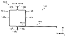
- FIG. 1 is a view showing a cross section perpendicular to the vehicle length direction L.
- the side sill 103 includes a hat-shaped side sill outer 104 and a hat-shaped side sill inner 105.
- a flange portion 102 a is formed at an end portion of the floor panel 102 in the vehicle width direction W (hereinafter referred to as “width direction end portion”), and the flange portion 102 a is joined to the top surface portion 105 a of the side sill inner 105.
- FIG. 3 is a view showing a cross section perpendicular to the vehicle length direction L, and the side sill 103 includes a hat-shaped side sill outer 104 and a hat-shaped side sill inner 105.
- the width direction end portion of the floor panel 102 is joined to the lower vertical wall portion 105 c of the side sill inner 105.
- the present invention has been made in view of such a problem of the prior art, and an object thereof is to provide a floor structure with improved proof stress.
- the inventor has intensively studied the side sill and floor panel mounting structure for transmitting a load from the side sill to the floor panel with in-plane force, and the cross-sectional deformation behavior of the side sill at the time of pole side collision.
- the present invention has been completed with knowledge. That is, the inventor joins the floor panel to the upper vertical wall portion or the lower vertical wall portion of the hat-shaped side sill inner, and the reinforcing member that suppresses the out-of-plane deformation of the upper vertical wall portion and the lower vertical wall portion. It has been found that the above problem can be solved by defining a value of W 1 / t, which is a ratio between the width W 1 of the vertical wall portion of the side sill inner and the plate thickness t of the vertical wall portion.
- one aspect of the present invention that solves the above problems is a floor structure, a side sill having a side sill outer and a side sill inner, a floor panel joined to the side sill inner, and an inner side of the side sill inner
- the side sill outer has a hat-shaped cross section perpendicular to the vehicle length direction, and a vertical wall portion extending from the top surface portion to the vehicle inner side in the vehicle width direction.
- a flange portion extending in the vehicle height direction
- the side sill inner has a hat-shaped cross section perpendicular to the vehicle length direction, and extends from the top surface portion to the vehicle outer side in the vehicle width direction.
- the side sill outer and the side sill inner are joined to each other by the flange part, and the side sill inner is provided.
- An angle ⁇ formed by the top surface portion and the vertical wall portion of the side sill inner is 85 to 95 degrees, and the floor panel is an upper vertical wall portion that is the vertical wall portion on the upper side in the vehicle height direction of the side sill inner.
- the reinforcing member is joined to the lower vertical wall portion which is the vertical wall portion on the vehicle height direction lower side of the side sill inner, the upper end portion of the reinforcing member is joined to the upper vertical wall portion of the side sill inner, and the lower end The portion is joined to the lower vertical wall portion of the side sill inner, and the value of W 1 / t, which is the ratio of the width W 1 of the vertical wall portion of the side sill inner and the thickness t of the vertical wall portion, is It is characterized by being less than 42.9.
- Another aspect of the present invention is a floor structure having a side sill outer and a side sill inner, a floor panel joined to the side sill inner, the side sill outer, and the side sill inner.
- the side sill outer has a hat-shaped cross section perpendicular to the vehicle length direction, and a vertical surface extending from the top surface portion to the vehicle inner side in the vehicle width direction.
- the side sill inner has a hat-shaped cross section perpendicular to the vehicle length direction, and includes a top surface portion and a vehicle in the vehicle width direction from the top surface portion.
- an angle ⁇ formed by the top surface portion of the side sill inner and the vertical wall portion of the side sill inner is 85 to 9 and has a vertical wall portion extending outward and a flange portion extending in the vehicle height direction.
- the floor panel is an upper vertical wall portion that is the vertical wall portion on the vehicle height direction upper side of the side sill inner, or a lower side that is the vertical wall portion on the lower side of the side sill inner in the vehicle height direction.
- the flange portion of the side sill outer, the reinforcing member, and the flange portion of the side sill inner are joined to each other, the width W 1 of the vertical wall portion of the side sill inner,
- the value of W 1 / t, which is a ratio to the wall thickness t, is less than 35.7.
- a floor structure with improved proof stress can be provided.
- FIG. 11 is a sectional view taken along line BB in FIG. 10.
- FIG. 11 is a view corresponding to the AA cross-sectional view of FIG. 10 showing an example of the shape of the floor panel.
- FIG. It is a figure which shows the example when the period C is not constant. It is a figure which shows the example in case the height h is not constant. It is a figure which shows the example in case the period C and height h are not constant. It is a figure which shows the analysis conditions of a side collision simulation (A). It is a figure which shows the deformation
- FIG. It is a figure which shows the deformation
- FIG. It is a figure which shows the analysis model in a side collision simulation (B).
- FIG. 1 It is a figure which shows the analysis model in a side collision simulation (B). It is CC sectional drawing of FIG. It is a figure which shows the analysis model in a side collision simulation (B). It is a figure which shows the relationship between the displacement of the pole in a comparative example and an Example, and the input load to a floor panel. In addition, the vertical axis
- FIG. It is a figure which shows the state of the out-of-plane deformation
- FIG. It is a figure which shows the relationship between the period C and the maximum input load when the height h / period C of the convex part of a floor panel is 0.067.
- shaft of this figure is represented by the maximum load ratio which normalized the maximum input load in each analysis model with the maximum input load of the comparative example 7.
- FIG. It is a figure which shows the relationship between C / (root) h of the convex part of a floor panel, and the mass efficiency of yield strength in each analysis model.
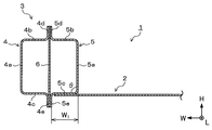
- the floor structure 1 of the first embodiment includes a floor panel 2 and a side sill 3.
- the side sill 3 includes a side sill outer 4 and a side sill inner 5.
- the side sill outer 4 is a member having a hat-shaped cross section perpendicular to the vehicle length direction L, and a top surface portion 4a extending in the vehicle height direction H, and an upper end portion of the top surface portion 4a in the vehicle height direction H in the vehicle width direction W.
- Upper vertical wall portion 4b extending to the vehicle interior side
- lower vertical wall portion 4c extending from the lower end portion in the vehicle height direction H of the top surface portion 4a to the vehicle inner side in the vehicle width direction W
- the tip portion of the upper vertical wall portion 4b 4d extending upward in the vehicle height direction H and a flange portion 4e extending downward in the vehicle height direction H from the tip of the lower vertical wall portion 4c.
- the side sill inner 5 is a member having a hat-shaped cross section perpendicular to the vehicle length direction L, and a top surface portion 5a extending in the vehicle height direction H, and an upper end portion of the top surface portion 5a in the vehicle height direction H in the vehicle width direction W.
- An upper vertical wall portion 5b extending to the vehicle outer side, a lower vertical wall portion 5c extending from the lower end portion in the vehicle height direction H of the top surface portion 5a to the vehicle outer side in the vehicle width direction W, and a tip portion of the upper vertical wall portion 5b
- the flange portion 5d extends upward in the vehicle height direction H, and the flange portion 5e extends downward from the front end portion of the lower vertical wall portion 5c in the vehicle height direction H.
- the side sill outer 4 and the side sill inner 5 are joined by spot welding of the flange portion 4d and the flange portion 5d, and the flange portion 4e and the flange portion 5e, respectively.
- the hat shape of the side sill outer 4 and the hat shape of the side sill inner 5 include, for example, a substantially hat shape in which the vertical wall portion is inclined with respect to the top surface portion.
- the angle ⁇ formed by the top surface portion 5a of the side sill inner 5 and the vertical wall portions 5b and 5c is 85 to 95 degrees. When the angle ⁇ is less than 85 degrees, the moment generated in the floor panel 2 that deforms the side sill 3 to the inside of the cross section increases.
- the angle ⁇ is preferably 87 degrees or more, and this can enhance the effect of suppressing the moment generated in the floor panel 2 that deforms the side sill 3 to the inside of the cross section.
- the angle ⁇ exceeds 95 degrees, the moment generated in the floor panel 2 that deforms the side sill 3 to the outside of the cross section increases.
- the angle ⁇ is preferably 93 degrees or less, which can enhance the effect of suppressing the moment generated in the floor panel 2 that deforms the side sill 3 to the outside of the cross section.
- a reinforcing member 6 is provided inside the side sill inner 5.
- the reinforcing member 6 is a member having a C-shaped cross section perpendicular to the vehicle length direction L, and includes a flat portion 6a and flange portions 6b and 6c formed at both ends of the flat portion 6a.
- the reinforcing member 6 is disposed such that the flat surface portion 6a of the reinforcing member 6 is parallel to the top surface portion 5a of the side sill inner 5 and the flange portion 6b and the flange portion 6c extend to the vehicle outer side in the vehicle width direction W. Has been.
- the flange portion 6b of the reinforcing member 6 is in contact with the inner surface of the upper vertical wall portion 5b of the side sill inner 5, and the flange portion 6c of the reinforcing member 6 is in contact with the inner surface of the lower vertical wall portion 5c of the side sill inner 5.
- the floor panel 2 is in contact with the outer surface of the lower vertical wall 5c of the side sill inner 5 at the end in the width direction. That is, in the lower vertical wall portion 5c of the side sill inner 5, the flange portion 6c of the reinforcing member 6 is in contact with the inner surface, and the width direction end portion of the floor panel 2 is in contact with the outer surface.
- the flange portion 6b of the reinforcing member 6 is joined to the upper vertical wall portion 5b of the side sill inner 5 by, for example, spot welding. Thereby, the reinforcing member 6 of 1st Embodiment is being fixed to the side sill inner 5 so that it may span over the upper side vertical wall part 5b and the lower side vertical wall part 5c.
- the floor structure 1 of the first embodiment is configured as described above.
- a load is transmitted to the floor panel 2 via the lower vertical wall portion 5 c of the side sill inner 5.
- the upper vertical wall portion 5b and the lower vertical wall portion 5c of the side sill inner 5 try to be deformed out of plane so as to open to the outside of the cross section or to fall inside the cross section.
- the reinforcing member 6 is joined in a state of being spanned between the upper vertical wall portion 5b and the lower vertical wall portion 5c, the upper vertical wall portion 5b of the side sill inner 5 and When the lower vertical wall portion 5c is deformed so as to open to the outside of the cross section, the reinforcing member 6 is pulled, and tension is generated in the reinforcing member 6.
- the reinforcing member 6 is compressed, and a compressive force is generated in the reinforcing member 6.
- the width W 1 of the vertical wall portions 5b and 5c of the side sill inner 5 (the length in the vehicle width direction W from the top surface portion 5a to the flange portions 5d and 5e).
- the balance between the vertical wall portions 5b and 5c and the plate thickness t is important.
- the value of W 1 / t which is the ratio of the width W 1 of the vertical wall portions 5b and 5c to the plate thickness t, is less than 42.9, and the floor structure 1 that satisfies this condition Then, it becomes possible to suppress the out-of-plane deformation of the vertical wall portions 5b and 5c.
- W 1 / t is preferably 40 or less, and more preferably 30 or less.
- the lower limit of W 1 / t is the moldability and the side sill inner 5, the vertical wall 5b, but determined appropriately in view of securing white welding 5c and the floor panel 2, W 1 / t that is 7.5 or more Is preferred.
- the width W 1 of the vertical wall portions 5b and 5c is preferably 15 mm or more in order to ensure a sufficient spot hitting space.
- the shape of the reinforcing member 6 is not particularly limited as long as the upper end portion is joined to the inner surface of the upper vertical wall portion 5b of the side sill inner 5 and the lower end portion is joined to the inner surface of the lower vertical wall portion 5c.
- the reinforcing member 6 has a shape that does not loosen, that is, a shape in which the upper vertical wall portion 5b and the lower vertical wall portion 5c are bridged over the shortest distance. Preferably there is.
- the reinforcing member 6 is arranged in such a direction that the flange portion 6b and the flange portion 6c of the reinforcing member 6 extend to the vehicle outer side in the vehicle width direction W.
- the flange portion 6b and the flange portion 6c are arranged. May be arranged in a direction extending toward the vehicle inner side in the vehicle width direction W.
- spot welding can be performed by sandwiching with a gun. Becomes easier.
- the reinforcing member 6 is configured by a flat plate member, and the reinforcing member 6 is disposed between the side sill outer 4 and the side sill inner 5.
- the flange portion 4d of the side sill outer 4 and the flange portion 5d of the side sill inner 5 are joined by, for example, spot welding in a state where the reinforcing member 6 is sandwiched therebetween.
- the flange portion 4e of the side sill outer 4 and the flange portion 5e of the side sill inner 5 are also joined by, for example, spot welding in a state where the reinforcing member 6 is sandwiched therebetween.
- the reinforcing member 6 can be joined at the same time. Thereby, a welding location can be decreased and productivity can be improved.
- the value of W 1 / t which is the ratio between the width W 1 of the vertical wall portions 5b and 5c of the side sill inner 5 and the plate thickness t, is less than 35.7.
- W 1 / t may be 32 or less from the viewpoint of further suppressing out-of-plane deformation. preferable.
- the lower limit of W 1 / t is the moldability and the side sill inner 5, the vertical wall 5b, but determined appropriately in view of securing white welding 5c and the floor panel 2, W 1 / t that is 7.5 or more Is preferred.
- a center pillar inner 7 is disposed between the side sill outer 4 and the side sill inner 5.
- the flange portion 4d of the side sill outer 4 and the flange portion 5d of the side sill inner 5 are joined together by, for example, spot welding with the center pillar inner 7 sandwiched therebetween.
- the flange portion 4e of the side sill outer 4 and the flange portion 5e of the side sill inner 5 are also joined by, for example, spot welding with the center pillar inner 7 sandwiched therebetween.
- the center pillar inner 7 also plays a role as the reinforcing member 6 of the second embodiment. That is, in the floor structure 1 of the third embodiment, the number of parts used for vehicle body manufacturing can be reduced, and the number of welding locations can be reduced as in the floor structure 1 of the second embodiment.
- the value of W 1 / t which is the ratio between the width W 1 of the vertical wall portions 5b and 5c of the side sill inner 5 and the plate thickness t, is less than 35.7. According to such a floor structure 1, the out-of-plane deformation that opens to the outside of the cross-section and the out-of-plane deformation that closes to the inside of the cross-section generated in the upper vertical wall portion 5 b and the lower vertical wall portion 5 c of the side sill inner 5 at the time of a side collision. Can be suppressed.
- W 1 / t is 32 or less from the viewpoint of further suppressing out-of-plane deformation. Is preferred.
- the lower limit of W 1 / t is the moldability and the side sill inner 5, the vertical wall 5b, but determined appropriately in view of securing white welding 5c and the floor panel 2, W 1 / t that is 7.5 or more Is preferred.
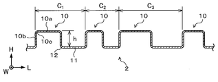
- the floor panel 2 of the fourth embodiment includes a periodically formed convex portion 10, a bottom surface portion 11, and a ridge line that is a corner portion connecting the convex portion 10 and the bottom surface portion 11. It has a wave shape having a portion 12.
- the convex part 10 of the floor panel 2 in 4th Embodiment is the corner
- the ridge lines 10c and 12 are parallel to the vehicle width direction W.
- the longitudinal direction of the convex portion 10 is parallel to the vehicle width direction W.
- the length of the top surface part 10a and the bottom face part 11 of the vehicle length direction L is mutually the same.
- Such a corrugated floor panel 2 is manufactured by imparting a shape to a flat plate by, for example, transfer by a roll or press molding.
- the floor structure 1 of the fourth embodiment is similar to the floor structure 1 (FIG. 5) of the first embodiment in the structure of the side sill 3 and the arrangement of the reinforcing members 6, and the vertical wall portions 5b and 5c.
- the value of W 1 / t which is the ratio of the width W 1 to the plate thickness t, is less than 42.9.
- the top surface portion 10 a of the convex portion 10 is joined to the lower vertical wall portion 5 c of the side sill inner 5.
- upper surface part 10a is 15 mm. The above is preferable.
- the floor structure 1 of the fourth embodiment is configured as described above.
- the height from the bottom surface portion 11 of the corrugated portion of the floor panel 2 to the top surface portion 10a is defined as h
- the period of the convex portion 10 of the corrugated portion is defined as C.
- “period of the convex portion” means an interval from a boundary position between the convex portion 10 and the bottom surface portion 11 to a boundary position between the convex portion 10 adjacent to the convex portion 10 and the bottom surface portion 11. To do.
- the period C is the space
- the period C is equal to the inner surface P 1 of the side wall portion 10 b of the first convex portion 10. is the spacing from the intersection of the lower surface P 2 of the bottom portion 11, an inner surface P 1 of the second side wall portion 10b of the protrusion 10, until the line of intersection of the lower surface P 2 of the bottom portion 11.
- out-of-plane deformation occurs in the top surface portion 10a and the bottom surface portion 11 of the floor panel 2 at the time of a side collision of an automobile, but as the period C becomes smaller, each top surface portion 10a and each bottom surface.
- the length of the portion 11 in the vehicle length direction L is shortened.
- the period C of the convex portion 10 is preferably 15 to 200 mm.
- the higher the height h the higher the bending rigidity against bending deformation with the vehicle length direction L as the rotation axis, so the proof stress of the floor panel 2 is easily improved. As a result, the proof stress of the floor structure 1 can be improved.
- the height h of the convex portion 10 is preferably 2 to 20 mm.
- the corrugated portion is formed so that C / ⁇ h is less than 60.
- the floor panel 2 in which C / ⁇ h is less than 60 has improved proof mass efficiency relative to a floor panel having C / ⁇ h of 60 or more.
- the proof strength can be improved by the side sill structure, and the floor panel 2 joined to the side sill inner 5 has a corrugated portion where C / ⁇ h is less than 60
- C / ⁇ h is preferably 55 or less, and more preferably 25 or less.
- the floor panel is preferably a steel plate having a tensile strength of 780 MPa or more.
- the floor structure 1 as in the fourth embodiment sufficient strength can be exerted without the floor panel 2 having a closed cross-sectional structure, so that the floor structure is configured without providing a reinforcing member such as a cross member. It is also possible to do. As a result, the indoor space or the battery mounting space can be expanded. However, from the viewpoint of improving the proof stress, the proof strength of the floor structure 1 can be further increased by further providing a reinforcing member such as a cross member to the floor structure 1 as in the fourth embodiment.
- FIG. 12 shows an example in which the floor panel 2 of the floor structure 1 of the first embodiment has a corrugated portion, but the floor panel of the floor structure 1 as in the second and third embodiments. 2 may have a corrugated portion.
- the corrugated portion with C / ⁇ h of less than 60 is provided on the floor panel, the mass efficiency of yield strength can be improved.
- the lower limit of C / ⁇ h is not particularly limited.
- the lower limit of the period C is constrained from the viewpoint of formability of the floor panel 2, or the upper limit of the height h is constrained from the viewpoint of securing indoor space or battery mounting space, and the lower limit of C / ⁇ h is appropriately determined.
- C / ⁇ h is preferably 3.34 or more.
- the floor panel 2 may not have a wave shape over the entire region in the vehicle length direction L, and only a part of the section in the vehicle length direction L may have a wave shape. Even in such a floor structure, if C / ⁇ h is less than 60 in the portion of the floor panel 2 to which the wave shape is given, the mass efficiency of yield strength is improved. Also in this case, C / ⁇ h is preferably 55 or less, and more preferably 25 or less.
- the range of the corrugated portion is, for example, 200 mm or more in front of the vehicle length direction L around the collision position of the pole in the pole side collision test, and the rear It is preferable that it is 200 mm or more.
- the floor panel 2 may not have a wave shape over the entire region in the vehicle width direction W, and only the end in the width direction may have a wave shape. Even in such a floor structure, if C / ⁇ h is less than 60 in the portion to which the corrugation at the end in the width direction is given, the mass efficiency of yield strength is improved. Also in this case, C / ⁇ h is preferably 55 or less, and more preferably 25 or less.
- the range of the corrugated part is the width of the floor panel 2 (from one side sill of the vehicle body to the other, starting from the end point in the vehicle width direction W of the floor panel 2. It is preferable that it is 1/4 or more of the length in the vehicle width direction W to the side sill.
- the period C of the convex part 10 of the floor panel 2 may not be constant.
- the “cycle C” is an average value of the cycles C of the convex portions 10.
- the cycle of the first convex portion 10 is “C 1 ”
- the second convex portion 10 located next to the first convex portion 10 is used.
- the period C in this specification is (C 1 + C 2). + C 3 ) / 3.
- C / ⁇ h is less than 60 in a portion where a wave shape is given, the mass efficiency of yield strength is improved.
- C / ⁇ h is preferably 55 or less, and more preferably 25 or less.
- C / ⁇ h may not be less than 60 over the entire region in the vehicle length direction L.
- the floor panel 2 has a wave shape over the entire region in the vehicle length direction L, the value of C / ⁇ h using the average period C and the height h of some sections in the vehicle length direction L If it is less than 60, the mass efficiency of yield strength is improved in the section. Therefore, if attention is paid to the section, the floor structure has C / ⁇ h of less than 60, and therefore it can be said to be an example of the floor structure according to the present invention.
- the height h of the convex part 10 of the floor panel 2 may not be constant.
- the “height h” is an average value of the heights h of the convex portions 10.
- the height of the first convex portion 10 is “h 1 ”, which is located next to the first convex portion 10.
- the height of the second convex portion 10 is “h 2 ” and the height of the third convex portion located next to the second convex portion 10 is “h 3 ”
- the height h in this specification is This is a value calculated by (h 1 + h 2 + h 3 ) / 3.
- C / ⁇ h is less than 60 in the portion where the wave shape is given, the mass efficiency of yield strength is improved.
- C / ⁇ h is preferably 55 or less, and more preferably 25 or less.
- C / ⁇ h may not be less than 60 over the entire region in the vehicle length direction L.
- the floor panel 2 has a wave shape over the entire region in the vehicle length direction L, the value of C / ⁇ h using the average value of the height h and the period C of some sections in the vehicle length direction L If it is less than 60, the mass efficiency of yield strength is improved in the section. Therefore, if attention is paid to the section, the floor structure has C / ⁇ h of less than 60, and therefore it can be said to be an example of the floor structure according to the present invention.
- the period C and height h of the convex part 10 of the floor panel 2 may not be constant, respectively.
- the “cycle C” in this case is the average value of the period C of each convex portion 10 as in FIG. 14, and the “height h” is the average of the height h of each convex portion 10 as in FIG. Value.
- the period C is calculated by (C 1 + C 2 + C 3 ) / 3
- C / ⁇ h is less than 60 in the portion where the wave shape is given, the mass efficiency of yield strength is improved.
- C / ⁇ h is preferably 55 or less, and more preferably 25 or less.
- C / ⁇ h may not be less than 60 over the entire vehicle length direction L.
- C that is the average period of some sections in the vehicle length direction L and h that is the average height of the sections are used.
- the floor structure has C / ⁇ h of less than 60, and therefore it can be said to be an example of the floor structure according to the present invention.
- the height h of the convex portion 10 of the floor panel 2 may be different depending on the position in the vehicle width direction W.
- the “height h” is an average value of heights different from each other at the position in the vehicle width direction W.
- C / ⁇ h is less than 60 in the portion to which the wave shape is given, the mass efficiency of yield strength is improved.
- C / ⁇ h is preferably 55 or less, and more preferably 25 or less.
- C / ⁇ h may not be less than 60 over the entire region in the vehicle width direction W.
- ⁇ h is less than 60, the yield strength of the floor panel 2 is improved.
- the range in which C / ⁇ h in this case is less than 60 is the width of the floor panel 2 (the vehicle width direction W from one side sill of the vehicle body to the other side sill, starting from the end point of the floor panel 2 in the vehicle width direction W).
- the length is preferably 1 ⁇ 4 or more of the length.
- the convex portion 10 of the floor panel 2 is configured by the top surface portion 10a, the side wall portion 10b, and the ridge line portion 10c.
- the shape of the convex portion 10 is not particularly limited.
- the cross-sectional shape perpendicular to the longitudinal direction may be circular.
- the “height h” is a height from the bottom surface portion 11 to the farthest position of the convex portion 10.
- C / ⁇ h is preferably 55 or less, and more preferably 25 or less.
- the ridgeline portions 10c and 12 of the floor panel 2 are parallel to the vehicle width direction W and the floor structure is adapted to the side collision, but the ridgeline portions 10c and 12 are arranged in the vehicle length direction L of the floor panel 2. It is good also as a floor structure corresponding to front collision or rear collision. Even in such a floor structure, if C / ⁇ h is less than 60 in the portion to which the wave shape is given, the mass efficiency of yield strength is improved. Also in this case, C / ⁇ h is preferably 55 or less, and more preferably 25 or less.
- the floor panel 2 may not be corrugated over the entire region in the vehicle width direction W, and only a portion of the section in the vehicle width direction W is corrugated. There may be. Even in such a floor structure, if C / ⁇ h is less than 60 in the portion of the floor panel 2 to which the wave shape is given, the mass efficiency of yield strength is improved. Also in this case, C / ⁇ h is preferably 55 or less, and more preferably 25 or less.
- the range of the wave shape portion is, for example, 200 mm or more from the center position in the vehicle width direction W of the floor panel 2 to the right in the vehicle width direction W, And it is preferable that it is 200 mm or more to the left.
- the floor panel 2 may not be wavy throughout the vehicle length direction L.
- the end portion of the vehicle length direction L (hereinafter referred to as “longitudinal direction”). Only the edge ”) may be wavy.
- C / ⁇ h is less than 60 in the portion where the corrugation at the end in the longitudinal direction is applied, the mass efficiency of yield strength is improved. Also in this case, C / ⁇ h is preferably 55 or less, and more preferably 25 or less.
- the range of the corrugated portion is 1 of the length from the front end to the rear end of the floor panel 2 starting from the end point of the floor panel 2 in the vehicle length direction L. / 4 or more is preferable.
- the period C of the convex part 10 of the floor panel 2 may not be constant.
- the “cycle C” is an average value of the cycles C of the convex portions 10. Even in such a floor structure, if C / ⁇ h is less than 60 in the portion to which the wave shape is given, the mass efficiency of yield strength is improved. Also in this case, C / ⁇ h is preferably 55 or less, and more preferably 25 or less. If the period C is not constant, C / ⁇ h may not be less than 60 over the entire region in the vehicle width direction W.
- the floor structure has C / ⁇ h of less than 60, and therefore it can be said to be an example of the floor structure according to the present invention.
- the height h of the convex portion 10 of the floor panel 2 may not be constant.
- the “height h” is an average value of the heights h of the convex portions 10. Even in such a floor structure, if C / ⁇ h is less than 60 in the portion to which the wave shape is given, the mass efficiency of yield strength is improved. Also in this case, C / ⁇ h is preferably 55 or less, and more preferably 25 or less. When the height h is not constant, C / ⁇ h may not be less than 60 over the entire region in the vehicle width direction W.
- the floor structure has C / ⁇ h of less than 60, and therefore it can be said to be an example of the floor structure according to the present invention.
- the period C and the height h of the convex portion 10 of the floor panel 2 may not be constant.
- “period C” is an average value of the periods C of the respective convex portions 10
- “height h” is an average value of the height h of each convex portion 10.
- C / ⁇ h may not be less than 60 over the entire region in the vehicle width direction W.
- C that is the average period of a part of the section in the vehicle width direction W and h that is the average height of the section are used. If the value of C / ⁇ h is less than 60, the mass efficiency of yield strength is improved in the section. Therefore, if attention is paid to the section, the floor structure has C / ⁇ h of less than 60, and therefore it can be said to be an example of the floor structure according to the present invention.
- the height h of the convex portion 10 of the floor panel 2 may be different depending on the position in the vehicle length direction L.
- the “height h” in this case is an average value of heights that are different at the position in the vehicle length direction L.
- C / ⁇ h is less than 60 in the portion to which the wave shape is given, the mass efficiency of yield strength is improved.
- C / ⁇ h is preferably 55 or less, and more preferably 25 or less.
- C / ⁇ h may not be less than 60 over the entire region in the vehicle length direction L, and C / only at the longitudinal end portion. If ⁇ h is less than 60, the yield strength of the floor panel 2 is improved. In this case, the range in which C / ⁇ h is less than 60 may be 1 ⁇ 4 or more of the length from the front end to the rear end of the floor panel 2 starting from the end point of the floor panel 2 in the vehicle length direction L. preferable.
- the floor panel 2 is joined to the lower vertical wall portion 5c of the side sill inner 5, but may be joined to the upper vertical wall portion 5b. Also in this case, for example, by providing the reinforcing member 6 as in the first to fourth embodiments, out-of-plane deformation of the upper vertical wall portion 5b and the lower vertical wall portion 5c of the side sill inner 5 is suppressed. The load transmission efficiency to the floor panel 2 can be improved.
- ⁇ Side collision simulation (A)> In order to evaluate the influence of the side sill structure in the conventional floor structure and the floor structure according to the present invention, a side collision simulation was performed. As shown in FIG. 17, this simulation is performed under the condition of three-point bending in which a support point 20 that supports the top surface portion 5 a of the side sill inner 5 is provided and the pole 21 collides with the side sill outer 4. In addition, a plate 22 that contacts the top surface portion 5a of the side sill inner 5 is disposed to simulate a structure assuming a battery case.
- the floor structure of the analysis model used in this simulation includes a structure in which the reinforcing member shown in FIG. 3 is not provided, and a structure in which a C-shaped reinforcing member 6 is provided inward of the side sill inner 5 shown in FIG. 7 is a structure in which a flat reinforcing member 6 is provided between the side sill outer 4 and the side sill inner 5 shown in FIG. Further, in each structure, a plurality of analysis models in which the width W 1 of the lower vertical wall portion 5c of the side sill inner 5 was changed were created and simulated.
- the materials of the side sill outer 4, the side sill inner 5, and the reinforcing member 6 are all 980 MPa grade steel plates, and the thickness t is 1.4 mm.
- the angle ⁇ formed between the top surface portion of the side sill inner and the vertical wall portion is 90 degrees.
- the side sill inner had an out-of-plane deformation whose cross section opened outward.
- the result varies depending on the value of W 1 / t, which is the ratio of the width W 1 of the vertical wall portion of the side sill inner to the plate thickness t. occured.
- W 1 / t which is the ratio of the width W 1 of the vertical wall portion of the side sill inner to the plate thickness t.
- Example 7 A side impact simulation of the floor structure was conducted assuming a pole side impact.
- the floor structure of the analysis model used in this simulation is the structure having the flat floor panel shown in FIG. 22 (Comparative Example 7) and the flat floor panel as shown in FIG. This is a structure using a cross-member for bonding (Comparative Example 8) and a corrugated floor panel shown in FIG.
- a plurality of analysis models in which the period C and the height h of the convex portion were changed were created and simulated (Examples 4 to 13).
- the structure of Example 13 is a structure in which a cross member is joined to a corrugated floor panel. In this simulation, the evaluation is performed by paying attention to the proof stress of the floor panel. Therefore, the side sill is replaced with an elastic plate having a thickness of 6 mm.
- Table 2 shows the conditions of the analysis model of the side collision simulation and the maximum load ratio (F 1 / F 0 ) obtained by normalizing the maximum input load F 1 of each analysis model with the maximum input load F 0 of Comparative Example 7.
- the mass ratio (m 1 / m 0 ) obtained by normalizing the mass m 1 of each analysis model with the mass m 0 of Comparative Example 7 is also shown.
- FIG. 26 shows displacement-load ratio diagrams of Comparative Example 7 and Examples 4 and 5.
- the load ratio shown in FIG. 26 is a value obtained by normalizing the input load in each analysis model with the maximum input load of Comparative Example 7.
- the input load decreases and changes.
- the reason for such transition is that the floor panel undergoes a large deformation after the input load reaches the maximum load. That is, the maximum input load is an input load before the floor panel is largely deformed, and corresponds to a proof stress. Therefore, according to FIG. 26, it is shown that the proof stress of the floor structure of Example 4 is higher than that of Comparative Example 7.
- FIG. 27 shows the state of the out-of-plane deformation caused by the simulation of the analysis model of Comparative Example 7.
- FIG. 28 shows a state of out-of-plane deformation caused by the simulation of the analysis model of the fourth embodiment.
- the top surface portion 10a and the bottom surface portion 11 of the convex portion are individually deformed out of plane.
- region of an out-of-plane deformation at the time of seeing as the whole floor panel is narrower than the flat floor panel shown in FIG.
- the reason why the top surface portion 10a and the bottom surface portion 11 are individually deformed out of plane is that the ridge line portion 10c (FIG. 11) connecting the top surface portion 10a and the side wall portion 10b, and the ridge line connecting the bottom surface portion 11 and the side wall portion 10b. Since the extending direction of the portion 12 (FIG.
- each ridge line portion 10c, 12 serves as a support point during bending deformation. This is because it works.
- the space between the supporting points is a region where the out-of-plane deformation of the floor panel can occur, but the interval between the supporting points is shortened because the floor panel is corrugated, and the span of bending deformation is changed to a flat floor panel. On the other hand, it becomes shorter. Thereby, in the floor panel of Example 4, resistance to bending deformation is increased, and the proof stress is greater than that of a floor panel that is not corrugated.
- Example 4 and Example 5 are compared in FIG. 26, the maximum load in Example 5 is larger than that in Example 4, while the attenuation of the input load after reaching the maximum load is in Example 4. Is smaller.
- the maximum load before the large deformation of the floor panel is smaller in the fourth embodiment than in the fifth embodiment, but the input load after the large deformation of the floor panel is kept high. Therefore, it can be said that the floor structure of Example 4 is a structure having higher energy absorption performance than that of Example 5, but from the viewpoint of exhibiting high proof strength before large deformation of the floor panel, Is better. This result shows that a floor structure with high energy absorption performance is not necessarily a structure with high yield strength.
- FIG. 29 shows the maximum load ratio F 1 / F obtained by normalizing the convex portion period C of each analysis model having a corrugated floor panel and the maximum input load F 1 of each analysis model by the maximum input load F 0 of Comparative Example 7. The relationship with F 0 is shown.
- the plot in FIG. 29 corresponds to the results of Comparative Example 11 and Examples 4 to 8 in Table 2 above, and is the case where h / C is all 0.067 and constant. When h / C is constant, the line length of the floor panel in the cross-sectional view as shown in FIG. 11 is constant, and the proof stress can be evaluated under the condition of constant mass.
- Example 29 shows that, under a constant mass condition, the proof strength of the floor panel is increased by reducing the period C rather than increasing the height h of the convex portion.
- the plot in the case where the period C in FIG. 29 is 30 mm corresponds to the result of Example 5 in Table 2 above, but according to Table 2 above, the plot is more implemented than Comparative Example 8 which is a floor structure having a cross member.
- Example 5 has a larger maximum load ratio. From this result, the floor structure of Example 5 shows that the proof stress increases so that the cross member for dealing with the pole side collision can be omitted.
- FIG. 30 shows that the C / ⁇ h of the convex portion of the floor panel and the maximum load ratio F 1 / F 0 of each analysis model are normalized by the mass ratio m 1 / m 0 based on Comparative Example 7. Show the relationship.
- the value on the vertical axis in FIG. 30 is the mass efficiency of the yield strength indicating the magnitude of the yield strength per mass, and the higher the value on the vertical axis, the better the balance between the yield strength and the mass.
- FIG. 30 shows that the smaller the value of C / ⁇ h, the better the mass efficiency.
- the proof stress mass efficiency may be inferior to that of the flat floor panel comparative example 7. That is, it is impossible to achieve both yield strength and weight reduction by simply making the floor panel corrugated.
- the floor structure that is superior in mass efficiency of yield strength to Comparative Example 7 is a floor structure in which C / ⁇ h is less than 60. Therefore, when the corrugated portion is provided on the floor panel, C / ⁇ h is preferably less than 60 from the viewpoint of improving the mass efficiency of yield strength.
- the present invention can be used as a floor structure attached to a vehicle such as an automobile.
Abstract
The present invention provides a floor structure that is provided with: a side sill that has a hat-shaped side sill outer and a hat-shaped side sill inner; a floor panel that is joined to the side sill inner; and a reinforcement member that is disposed at an inner side of the side sill inner, wherein the side sill outer and the side sill inner are joined at flange sections thereof; an angle θ formed by a top-surface section and a vertical-wall section of the side sill inner is 85 to 95 degrees; the floor panel is joined to an upper vertical-wall section or a lower vertical-wall section of the side sill inner; an upper end section of the reinforcement member is joined to the upper vertical-wall section, and a lower end section of the reinforcement member is joined to the lower vertical-wall section; and the value of W1/t, which is the ratio of the width W1 of the vertical-wall section of the side sill inner to the plate thickness t of the vertical-wall section thereof, is less than 42.9.
Description
本発明は、自動車のフロア構造に関する。
The present invention relates to an automobile floor structure.
自動車のフロア構造は、例えばフロアパネル、サイドシル、フロアクロスメンバおよびその他補強部材等からなる。このようなフロア構造では、例えば自動車の側面衝突時、特にポール側面衝突時において、主にサイドシルの曲げ変形とフロアクロスメンバの圧潰変形により衝撃を吸収することで、乗員の生存空間を確保している。この時、フロアパネルには、乗員の生存空間の確保のために大変形しないこと、およびサイドシルからの荷重を支持することが求められる。
The floor structure of an automobile includes, for example, a floor panel, a side sill, a floor cross member, and other reinforcing members. In such a floor structure, for example, at the time of a side collision of an automobile, in particular, at the time of a pole side collision, a shock is absorbed mainly by bending deformation of the side sill and crushing deformation of the floor cross member, thereby securing a living space for the occupant. Yes. At this time, the floor panel is required not to be greatly deformed in order to secure the occupant's living space and to support the load from the side sill.
近年、電気自動車の航続距離を高めることを目的に、フロアパネルの下に大容量のバッテリーを搭載する車体レイアウトが採用され始めている。このようなレイアウトの車体では、ポール側面衝突時の電気安全の観点から、バッテリーが損傷しないよう、サイドシルの変形で確実に衝撃を吸収することが望まれる。そのため、サイドシルの変形時の耐荷重性能を高めなければならず、フロアパネルには、自身が大変形しないようサイドシルから伝達されるその高い荷重に耐えることが求められる。なお、フロアパネル等の部材は大変形することで部材に入力される荷重が大変形前より小さくなるが、本明細書においては部材が大変形する前の最大入力荷重を“耐力”と称す。
In recent years, a vehicle body layout in which a large-capacity battery is mounted under the floor panel has been adopted for the purpose of increasing the cruising range of an electric vehicle. In the vehicle body having such a layout, it is desired that the impact is surely absorbed by the deformation of the side sill so as not to damage the battery from the viewpoint of electrical safety at the time of a pole side collision. Therefore, it is necessary to enhance the load bearing performance when the side sill is deformed, and the floor panel is required to withstand the high load transmitted from the side sill so that the floor panel does not deform greatly. Note that a member such as a floor panel is greatly deformed so that a load input to the member is smaller than that before the large deformation. However, in this specification, the maximum input load before the member is largely deformed is referred to as “proof strength”.
一方、電気自動車では、従来の自動車に対し、プロペラシャフトと呼ばれる駆動部品や排気管が不要になる。そのため、フロアパネルの車幅方向の中央部に設けられるトンネルと呼ばれる段差形状が不要となり、フロアパネルを略フラットな形状にすることができる。プレス成形等の加工の観点では、略フラットなフロアパネルは従来のフロアパネルに比べてエンボスなどの形状付与が容易になる。
On the other hand, in an electric vehicle, a driving component called a propeller shaft and an exhaust pipe are not required compared to a conventional vehicle. Therefore, a step shape called a tunnel provided at the center of the floor panel in the vehicle width direction is not required, and the floor panel can be formed into a substantially flat shape. From the viewpoint of processing such as press molding, a substantially flat floor panel can be easily provided with a shape such as emboss as compared with a conventional floor panel.
従来のフロア構造として、特許文献1に記載されたものがある。特許文献1には、キャブオーバー型のキャブフロアの補強構造として、キャブフロアの前部の、車幅方向の中央部の下面に補強部材が接合された構造が開示されている。特許文献1のフロア構造は、補強部材の車幅方向端部のフランジ部が、補強部材の左右に配置されたアンダーフレームに当接した状態で接合されている。
There is a conventional floor structure described in Patent Document 1. Patent Document 1 discloses a structure in which a reinforcing member is joined to the lower surface of the center portion in the vehicle width direction of the front portion of the cab floor as a cab over type cab floor reinforcing structure. The floor structure of Patent Document 1 is joined in a state in which the flange portion at the end in the vehicle width direction of the reinforcing member is in contact with the underframes disposed on the left and right of the reinforcing member.
フロア構造には耐力の向上が求められるが、特許文献1のフロア構造では、側面衝突の際に補強部材の車幅方向端部のフランジ部に局所的に荷重が入力され、その局所的な部分を介して荷重がキャブフロアに伝達されるため、荷重伝達効率が低い。
The floor structure is required to have improved yield strength. However, in the floor structure disclosed in Patent Document 1, a load is locally input to the flange portion at the end of the reinforcing member in the vehicle width direction at the time of a side collision, and the local portion Since the load is transmitted to the cab floor through the load, the load transmission efficiency is low.
また、従来のフロア構造として、例えば図1のようなフロアパネル102とサイドシル103とを有するフロア構造101がある。図1は車長方向Lに垂直な断面を示す図であり、サイドシル103は、ハット形状のサイドシルアウタ104と、ハット形状のサイドシルインナ105で構成されている。フロアパネル102の車幅方向Wの端部(以下、“幅方向端部”)にはフランジ部102aが形成され、フランジ部102aはサイドシルインナ105の天面部105aに接合されている。このようなフロア構造101の場合、例えばポール側面衝突試験でサイドシルアウタ104にポールが衝突すると、図2のようにサイドシルインナ105の車高方向Hの上側の縦壁部105b(以下、“上側縦壁部”)と、車高方向Hの下側の縦壁部105c(以下、“下側縦壁部”)が、断面の外側に開くようにして面外変形が生じる。このように面外変形しながらフロアパネル102に荷重が伝達される場合、荷重伝達効率が低下するだけでなく、フロアパネル102の面外変形が誘発され、耐力を十分に向上させることができない。
As a conventional floor structure, for example, there is a floor structure 101 having a floor panel 102 and a side sill 103 as shown in FIG. FIG. 1 is a view showing a cross section perpendicular to the vehicle length direction L. The side sill 103 includes a hat-shaped side sill outer 104 and a hat-shaped side sill inner 105. A flange portion 102 a is formed at an end portion of the floor panel 102 in the vehicle width direction W (hereinafter referred to as “width direction end portion”), and the flange portion 102 a is joined to the top surface portion 105 a of the side sill inner 105. In the case of such a floor structure 101, for example, when the pole collides with the side sill outer 104 in the pole side collision test, as shown in FIG. Out-of-plane deformation occurs in such a manner that the wall portion “) and the lower vertical wall portion 105c (hereinafter referred to as“ lower vertical wall portion ”) in the vehicle height direction H open to the outside of the cross section. When the load is transmitted to the floor panel 102 while being deformed out of plane in this way, not only the load transmission efficiency is lowered, but the out-of-plane deformation of the floor panel 102 is induced and the proof stress cannot be sufficiently improved.
また、従来のフロア構造として、例えば図3のようなフロアパネル102とサイドシル103とを有するフロア構造101がある。図3は車長方向Lに垂直な断面を示す図であり、サイドシル103は、ハット形状のサイドシルアウタ104と、ハット形状のサイドシルインナ105で構成されている。フロアパネル102の幅方向端部はサイドシルインナ105の下側縦壁部105cに接合されている。このようなフロア構造101の場合、例えばポール側面衝突試験でサイドシルアウタ104にポールが衝突すると、図4のようにサイドシルインナ105の上側縦壁部105bと下側縦壁部105cが、断面の外側に開くようにして面外変形が生じる。このように面外変形しながらフロアパネル102に荷重が伝達される場合、荷重伝達効率が低下するだけでなく、フロアパネル102の面外変形が誘発され、耐力を十分に向上させることができない。
Further, as a conventional floor structure, for example, there is a floor structure 101 having a floor panel 102 and a side sill 103 as shown in FIG. FIG. 3 is a view showing a cross section perpendicular to the vehicle length direction L, and the side sill 103 includes a hat-shaped side sill outer 104 and a hat-shaped side sill inner 105. The width direction end portion of the floor panel 102 is joined to the lower vertical wall portion 105 c of the side sill inner 105. In the case of such a floor structure 101, for example, when the pole collides with the side sill outer 104 in the pole side collision test, the upper vertical wall portion 105b and the lower vertical wall portion 105c of the side sill inner 105 are outside the cross section as shown in FIG. When it opens, the out-of-plane deformation occurs. When the load is transmitted to the floor panel 102 while being deformed out of plane in this way, not only the load transmission efficiency is lowered, but the out-of-plane deformation of the floor panel 102 is induced and the proof stress cannot be sufficiently improved.
本発明は、従来技術が有するこのような課題に鑑みてなされたものであり、耐力が向上したフロア構造を提供することを目的とする。
The present invention has been made in view of such a problem of the prior art, and an object thereof is to provide a floor structure with improved proof stress.
上記課題を解決するため、本発明者は、サイドシルからフロアパネルへ面内力で荷重を伝達するサイドシルとフロアパネルの取り付け構造、およびポール側面衝突時のサイドシルの断面変形挙動について鋭意検討し、以下の知見を以て本発明を完成した。すなわち、本発明者は、ハット形状のサイドシルインナの上側縦壁部または下側縦壁部にフロアパネルを接合し、上側縦壁部および下側縦壁部の面外変形を抑制する補強部材を設け、サイドシルインナの縦壁部の幅W1と、当該縦壁部の板厚tとの比であるW1/tの値を規定することにより上記課題を解決できることを見出した。
In order to solve the above-mentioned problems, the inventor has intensively studied the side sill and floor panel mounting structure for transmitting a load from the side sill to the floor panel with in-plane force, and the cross-sectional deformation behavior of the side sill at the time of pole side collision. The present invention has been completed with knowledge. That is, the inventor joins the floor panel to the upper vertical wall portion or the lower vertical wall portion of the hat-shaped side sill inner, and the reinforcing member that suppresses the out-of-plane deformation of the upper vertical wall portion and the lower vertical wall portion. It has been found that the above problem can be solved by defining a value of W 1 / t, which is a ratio between the width W 1 of the vertical wall portion of the side sill inner and the plate thickness t of the vertical wall portion.
したがって、上記課題を解決する本発明の一態様は、フロア構造であって、サイドシルアウタと、サイドシルインナと、を有するサイドシルと、前記サイドシルインナに接合されたフロアパネルと、前記サイドシルインナの内方に配置された補強部材と、を備え、前記サイドシルアウタは、車長方向に垂直な断面がハット形状であって、天面部と、前記天面部から車幅方向の車内側に延伸する縦壁部と、車高方向に延伸するフランジ部と、を有し、前記サイドシルインナは、車長方向に垂直な断面がハット形状であって、天面部と、前記天面部から車幅方向の車外側に延伸する縦壁部と、車高方向に延伸するフランジ部と、を有し、前記サイドシルアウタと前記サイドシルインナは、互いの前記フランジ部で接合され、前記サイドシルインナの前記天面部と前記サイドシルインナの前記縦壁部とのなす角θが85~95度であり、前記フロアパネルは、前記サイドシルインナの車高方向上側にある前記縦壁部である上側縦壁部、または前記サイドシルインナの車高方向下側にある前記縦壁部である下側縦壁部に接合され、前記補強部材は、上端部が前記サイドシルインナの前記上側縦壁部に接合され、下端部が前記サイドシルインナの前記下側縦壁部に接合され、前記サイドシルインナの前記縦壁部の幅W1と、該縦壁部の板厚tとの比であるW1/tの値が42.9未満であることを特徴としている。
Therefore, one aspect of the present invention that solves the above problems is a floor structure, a side sill having a side sill outer and a side sill inner, a floor panel joined to the side sill inner, and an inner side of the side sill inner The side sill outer has a hat-shaped cross section perpendicular to the vehicle length direction, and a vertical wall portion extending from the top surface portion to the vehicle inner side in the vehicle width direction. And a flange portion extending in the vehicle height direction, and the side sill inner has a hat-shaped cross section perpendicular to the vehicle length direction, and extends from the top surface portion to the vehicle outer side in the vehicle width direction. The side sill outer and the side sill inner are joined to each other by the flange part, and the side sill inner is provided. An angle θ formed by the top surface portion and the vertical wall portion of the side sill inner is 85 to 95 degrees, and the floor panel is an upper vertical wall portion that is the vertical wall portion on the upper side in the vehicle height direction of the side sill inner. Or, the reinforcing member is joined to the lower vertical wall portion which is the vertical wall portion on the vehicle height direction lower side of the side sill inner, the upper end portion of the reinforcing member is joined to the upper vertical wall portion of the side sill inner, and the lower end The portion is joined to the lower vertical wall portion of the side sill inner, and the value of W 1 / t, which is the ratio of the width W 1 of the vertical wall portion of the side sill inner and the thickness t of the vertical wall portion, is It is characterized by being less than 42.9.
また、別の観点による本発明の一態様は、フロア構造であって、サイドシルアウタと、サイドシルインナと、を有するサイドシルと、前記サイドシルインナに接合されたフロアパネルと、前記サイドシルアウタと前記サイドシルインナの間に配置された補強部材と、を備え、前記サイドシルアウタは、車長方向に垂直な断面がハット形状であって、天面部と、前記天面部から車幅方向の車内側に延伸する縦壁部と、車高方向に延伸するフランジ部と、を有し、前記サイドシルインナは、車長方向に垂直な断面がハット形状であって、天面部と、前記天面部から車幅方向の車外側に延伸する縦壁部と、車高方向に延伸するフランジ部と、を有し、前記サイドシルインナの前記天面部と前記サイドシルインナの前記縦壁部とのなす角θが85~95度であり、前記フロアパネルは、前記サイドシルインナの車高方向上側にある前記縦壁部である上側縦壁部、または前記サイドシルインナの車高方向下側にある前記縦壁部である下側縦壁部に接合され、前記サイドシルアウタの前記フランジ部と、前記補強部材と、前記サイドシルインナの前記フランジ部とが互いに接合され、前記サイドシルインナの前記縦壁部の幅W1と、該縦壁部の板厚tとの比であるW1/tの値が35.7未満であることを特徴としている。
Another aspect of the present invention according to another aspect is a floor structure having a side sill outer and a side sill inner, a floor panel joined to the side sill inner, the side sill outer, and the side sill inner. The side sill outer has a hat-shaped cross section perpendicular to the vehicle length direction, and a vertical surface extending from the top surface portion to the vehicle inner side in the vehicle width direction. The side sill inner has a hat-shaped cross section perpendicular to the vehicle length direction, and includes a top surface portion and a vehicle in the vehicle width direction from the top surface portion. And an angle θ formed by the top surface portion of the side sill inner and the vertical wall portion of the side sill inner is 85 to 9 and has a vertical wall portion extending outward and a flange portion extending in the vehicle height direction. The floor panel is an upper vertical wall portion that is the vertical wall portion on the vehicle height direction upper side of the side sill inner, or a lower side that is the vertical wall portion on the lower side of the side sill inner in the vehicle height direction. The flange portion of the side sill outer, the reinforcing member, and the flange portion of the side sill inner are joined to each other, the width W 1 of the vertical wall portion of the side sill inner, The value of W 1 / t, which is a ratio to the wall thickness t, is less than 35.7.
本発明によれば、耐力が向上したフロア構造を提供することができる。
According to the present invention, a floor structure with improved proof stress can be provided.
以下、本発明の実施形態について、図面を参照しながら説明する。なお、本明細書および図面において、実質的に同一の機能構成を有する要素においては、同一の符号を付することにより重複説明を省略する。
Hereinafter, embodiments of the present invention will be described with reference to the drawings. In the present specification and drawings, elements having substantially the same functional configuration are denoted by the same reference numerals, and redundant description is omitted.
<第1実施形態>
図5に示すように第1実施形態のフロア構造1は、フロアパネル2とサイドシル3で構成されている。サイドシル3は、サイドシルアウタ4と、サイドシルインナ5で構成されている。 <First Embodiment>
As shown in FIG. 5, thefloor structure 1 of the first embodiment includes a floor panel 2 and a side sill 3. The side sill 3 includes a side sill outer 4 and a side sill inner 5.
図5に示すように第1実施形態のフロア構造1は、フロアパネル2とサイドシル3で構成されている。サイドシル3は、サイドシルアウタ4と、サイドシルインナ5で構成されている。 <First Embodiment>
As shown in FIG. 5, the
サイドシルアウタ4は、車長方向Lに垂直な断面がハット形状の部材であり、車高方向Hに延伸する天面部4aと、天面部4aの車高方向Hの上端部から車幅方向Wの車内側に延伸する上側縦壁部4bと、天面部4aの車高方向Hの下端部から車幅方向Wの車内側に延伸する下側縦壁部4cと、上側縦壁部4bの先端部から車高方向Hの上方に延伸するフランジ部4dと、下側縦壁部4cの先端部から車高方向Hの下方に延伸するフランジ部4eとを有している。
The side sill outer 4 is a member having a hat-shaped cross section perpendicular to the vehicle length direction L, and a top surface portion 4a extending in the vehicle height direction H, and an upper end portion of the top surface portion 4a in the vehicle height direction H in the vehicle width direction W. Upper vertical wall portion 4b extending to the vehicle interior side, lower vertical wall portion 4c extending from the lower end portion in the vehicle height direction H of the top surface portion 4a to the vehicle inner side in the vehicle width direction W, and the tip portion of the upper vertical wall portion 4b 4d extending upward in the vehicle height direction H and a flange portion 4e extending downward in the vehicle height direction H from the tip of the lower vertical wall portion 4c.
サイドシルインナ5は、車長方向Lに垂直な断面がハット形状の部材であり、車高方向Hに延伸する天面部5aと、天面部5aの車高方向Hの上端部から車幅方向Wの車外側に延伸する上側縦壁部5bと、天面部5aの車高方向Hの下端部から車幅方向Wの車外側に延伸する下側縦壁部5cと、上側縦壁部5bの先端部から車高方向Hの上方に延伸するフランジ部5dと、下側縦壁部5cの先端部から車高方向Hの下方に延伸するフランジ部5eとを有している。
The side sill inner 5 is a member having a hat-shaped cross section perpendicular to the vehicle length direction L, and a top surface portion 5a extending in the vehicle height direction H, and an upper end portion of the top surface portion 5a in the vehicle height direction H in the vehicle width direction W. An upper vertical wall portion 5b extending to the vehicle outer side, a lower vertical wall portion 5c extending from the lower end portion in the vehicle height direction H of the top surface portion 5a to the vehicle outer side in the vehicle width direction W, and a tip portion of the upper vertical wall portion 5b The flange portion 5d extends upward in the vehicle height direction H, and the flange portion 5e extends downward from the front end portion of the lower vertical wall portion 5c in the vehicle height direction H.
サイドシルアウタ4とサイドシルインナ5は、フランジ部4dとフランジ部5d、およびフランジ部4eとフランジ部5eとがそれぞれスポット溶接されることで接合されている。なお、サイドシルアウタ4のハット形状、およびサイドシルインナ5のハット形状には、例えば縦壁部が天面部に対して傾斜した略ハット形状も含まれる。サイドシルインナ5の天面部5aと縦壁部5b、5cのなす角θは85~95度となっている。角θが85度未満の場合、フロアパネル2に発生する、サイドシル3を断面内側に変形させるモーメントが大きくなる。これにより、せん断力による変形、すなわち面内変形による荷重伝達の効果が小さくなり、フロアパネル2への荷重伝達効率が低下する。角θは、87度以上であることが好ましく、これによりフロアパネル2に発生する、サイドシル3を断面内側に変形させるモーメントを抑制する効果を高めることができる。一方、角θが95度を超える場合、フロアパネル2に発生する、サイドシル3を断面外側に変形させるモーメントが大きくなる。これにより、せん断力による変形、すなわち面内変形による荷重伝達の効果が小さくなり、フロアパネル2への荷重伝達効率が低下する。角θは、93度以下であることが好ましく、これによりフロアパネル2に発生する、サイドシル3を断面外側に変形させるモーメントを抑制する効果を高めることができる。
The side sill outer 4 and the side sill inner 5 are joined by spot welding of the flange portion 4d and the flange portion 5d, and the flange portion 4e and the flange portion 5e, respectively. Note that the hat shape of the side sill outer 4 and the hat shape of the side sill inner 5 include, for example, a substantially hat shape in which the vertical wall portion is inclined with respect to the top surface portion. The angle θ formed by the top surface portion 5a of the side sill inner 5 and the vertical wall portions 5b and 5c is 85 to 95 degrees. When the angle θ is less than 85 degrees, the moment generated in the floor panel 2 that deforms the side sill 3 to the inside of the cross section increases. Thereby, the effect of load transmission by deformation due to shearing force, that is, in-plane deformation is reduced, and the efficiency of load transmission to the floor panel 2 is reduced. The angle θ is preferably 87 degrees or more, and this can enhance the effect of suppressing the moment generated in the floor panel 2 that deforms the side sill 3 to the inside of the cross section. On the other hand, when the angle θ exceeds 95 degrees, the moment generated in the floor panel 2 that deforms the side sill 3 to the outside of the cross section increases. Thereby, the effect of load transmission by deformation due to shearing force, that is, in-plane deformation is reduced, and the efficiency of load transmission to the floor panel 2 is reduced. The angle θ is preferably 93 degrees or less, which can enhance the effect of suppressing the moment generated in the floor panel 2 that deforms the side sill 3 to the outside of the cross section.
第1実施形態においては、サイドシルインナ5の内方に補強部材6が設けられている。補強部材6は、車長方向Lに垂直な断面がC字形状の部材であり、平面部6aと、平面部6aの両端部に形成されたフランジ部6b、6cとを有している。第1実施形態では、補強部材6の平面部6aがサイドシルインナ5の天面部5aに平行で、フランジ部6bおよびフランジ部6cが車幅方向Wの車外側に延伸する向きで補強部材6が配置されている。
In the first embodiment, a reinforcing member 6 is provided inside the side sill inner 5. The reinforcing member 6 is a member having a C-shaped cross section perpendicular to the vehicle length direction L, and includes a flat portion 6a and flange portions 6b and 6c formed at both ends of the flat portion 6a. In the first embodiment, the reinforcing member 6 is disposed such that the flat surface portion 6a of the reinforcing member 6 is parallel to the top surface portion 5a of the side sill inner 5 and the flange portion 6b and the flange portion 6c extend to the vehicle outer side in the vehicle width direction W. Has been.
補強部材6のフランジ部6bはサイドシルインナ5の上側縦壁部5bの内面に接し、補強部材6のフランジ部6cはサイドシルインナ5の下側縦壁部5cの内面に接している。そして、フロアパネル2は、幅方向端部がサイドシルインナ5の下側縦壁部5cの外面に接している。すなわち、サイドシルインナ5の下側縦壁部5cにおいては、内面に補強部材6のフランジ部6cが接し、外面にフロアパネル2の幅方向端部が接しており、この状態で例えばスポット溶接によって各部材が接合されている。また、補強部材6のフランジ部6bはサイドシルインナ5の上側縦壁部5bに例えばスポット溶接によって接合されている。これにより、第1実施形態の補強部材6は上側縦壁部5bと下側縦壁部5cに掛け渡されるようにしてサイドシルインナ5に固定されている。
The flange portion 6b of the reinforcing member 6 is in contact with the inner surface of the upper vertical wall portion 5b of the side sill inner 5, and the flange portion 6c of the reinforcing member 6 is in contact with the inner surface of the lower vertical wall portion 5c of the side sill inner 5. The floor panel 2 is in contact with the outer surface of the lower vertical wall 5c of the side sill inner 5 at the end in the width direction. That is, in the lower vertical wall portion 5c of the side sill inner 5, the flange portion 6c of the reinforcing member 6 is in contact with the inner surface, and the width direction end portion of the floor panel 2 is in contact with the outer surface. The members are joined. The flange portion 6b of the reinforcing member 6 is joined to the upper vertical wall portion 5b of the side sill inner 5 by, for example, spot welding. Thereby, the reinforcing member 6 of 1st Embodiment is being fixed to the side sill inner 5 so that it may span over the upper side vertical wall part 5b and the lower side vertical wall part 5c.
第1実施形態のフロア構造1は以上のように構成されている。このようなフロア構造1において、例えばポール側面衝突試験でサイドシルアウタ4にポールが衝突すると、サイドシルインナ5の下側縦壁部5cを介してフロアパネル2に荷重が伝達される。ポール側突時には、サイドシルインナ5の上側縦壁部5bと下側縦壁部5cが、断面の外側に開くように、または断面の内側に倒れこむように面外変形しようとするが、第1実施形態のフロア構造1においては、補強部材6が上側縦壁部5bと下側縦壁部5cとの間に架け渡された状態で接合されているため、サイドシルインナ5の上側縦壁部5bと下側縦壁部5cが、断面の外側に開くように変形した場合、補強部材6は引っ張られ、補強部材6に張力が発生する。一方、サイドシルインナ5の上側縦壁部5bと下側縦壁部5cが、断面の内側に倒れこむように変形した場合、補強部材6は圧縮され、補強部材6に圧縮力が発生する。これらの張力または圧縮力が、上側縦壁部5bと下側縦壁部5cの面外変形に対する抵抗力となり、図6のようにフロアパネル2が接合された下側縦壁部5cの面外変形が抑制される。これにより、フロアパネル2に伝達される荷重が下側縦壁部5cのせん断変形、すなわち面内変形による伝達となり、フロアパネル2への荷重伝達効率が向上する。その結果、フロア構造1としての耐力を向上させることができる。
The floor structure 1 of the first embodiment is configured as described above. In such a floor structure 1, for example, when a pole collides with the side sill outer 4 in a pole side collision test, a load is transmitted to the floor panel 2 via the lower vertical wall portion 5 c of the side sill inner 5. At the time of pole side collision, the upper vertical wall portion 5b and the lower vertical wall portion 5c of the side sill inner 5 try to be deformed out of plane so as to open to the outside of the cross section or to fall inside the cross section. In the floor structure 1 of the embodiment, since the reinforcing member 6 is joined in a state of being spanned between the upper vertical wall portion 5b and the lower vertical wall portion 5c, the upper vertical wall portion 5b of the side sill inner 5 and When the lower vertical wall portion 5c is deformed so as to open to the outside of the cross section, the reinforcing member 6 is pulled, and tension is generated in the reinforcing member 6. On the other hand, when the upper vertical wall portion 5b and the lower vertical wall portion 5c of the side sill inner 5 are deformed so as to fall inside the cross section, the reinforcing member 6 is compressed, and a compressive force is generated in the reinforcing member 6. These tensions or compressive forces become resistance against out-of-plane deformation of the upper vertical wall portion 5b and the lower vertical wall portion 5c, and are out of plane of the lower vertical wall portion 5c to which the floor panel 2 is joined as shown in FIG. Deformation is suppressed. Thereby, the load transmitted to the floor panel 2 is transmitted by shear deformation of the lower vertical wall portion 5c, that is, in-plane deformation, and the load transmission efficiency to the floor panel 2 is improved. As a result, the proof stress as the floor structure 1 can be improved.
このような面外変形を抑制する効果を得るためには、サイドシルインナ5の縦壁部5b、5cの幅W1(天面部5aからフランジ部5d、5eまでの車幅方向Wの長さ)と、縦壁部5b、5cの板厚tとのバランスが重要である。第1実施形態においては、その縦壁部5b、5cの幅W1と板厚tとの比であるW1/tの値が42.9未満となっており、この条件を満たすフロア構造1であれば、縦壁部5b、5cの面外変形を抑制することが可能となる。その効果をさらに高めるためには、W1/tが40以下であることが好ましく、30以下であることがより好ましい。W1/tの下限値は、サイドシルインナ5の成形性や、縦壁部5b、5cとフロアパネル2の溶接しろ確保の観点から適宜定まるが、W1/tは7.5以上であることが好ましい。また、サイドシルインナ5と補強部材6をスポット溶接で接合する場合、スポット打点のスペースを十分に確保するために縦壁部5b、5cの幅W1は15mm以上であることが好ましい。
In order to obtain the effect of suppressing such out-of-plane deformation, the width W 1 of the vertical wall portions 5b and 5c of the side sill inner 5 (the length in the vehicle width direction W from the top surface portion 5a to the flange portions 5d and 5e). The balance between the vertical wall portions 5b and 5c and the plate thickness t is important. In the first embodiment, the value of W 1 / t, which is the ratio of the width W 1 of the vertical wall portions 5b and 5c to the plate thickness t, is less than 42.9, and the floor structure 1 that satisfies this condition Then, it becomes possible to suppress the out-of-plane deformation of the vertical wall portions 5b and 5c. In order to further enhance the effect, W 1 / t is preferably 40 or less, and more preferably 30 or less. The lower limit of W 1 / t is the moldability and the side sill inner 5, the vertical wall 5b, but determined appropriately in view of securing white welding 5c and the floor panel 2, W 1 / t that is 7.5 or more Is preferred. Further, when the side sill inner 5 and the reinforcing member 6 are joined by spot welding, the width W 1 of the vertical wall portions 5b and 5c is preferably 15 mm or more in order to ensure a sufficient spot hitting space.
なお、補強部材6は、上端部がサイドシルインナ5の上側縦壁部5bの内面に接合され、下端部が下側縦壁部5cの内面に接合されていれば、その形状は特に限定されない。一方で、側面衝突時に生じる補強部材6の張力を高めるには、補強部材6が緩みのない形状、すなわち最短距離で上側縦壁部5bと下側縦壁部5cが架け渡されるような形状であることが好ましい。
The shape of the reinforcing member 6 is not particularly limited as long as the upper end portion is joined to the inner surface of the upper vertical wall portion 5b of the side sill inner 5 and the lower end portion is joined to the inner surface of the lower vertical wall portion 5c. On the other hand, in order to increase the tension of the reinforcing member 6 generated at the time of a side collision, the reinforcing member 6 has a shape that does not loosen, that is, a shape in which the upper vertical wall portion 5b and the lower vertical wall portion 5c are bridged over the shortest distance. Preferably there is.
また、第1実施形態においては、補強部材6のフランジ部6bおよびフランジ部6cが車幅方向Wの車外側に延伸する向きで補強部材6が配置されているが、フランジ部6bおよびフランジ部6cが車幅方向Wの車内側に延伸する向きで配置されていても良い。一方で、第1実施形態のようにフランジ部6bおよびフランジ部6cが車幅方向Wの車外側に延伸する向きで配置されていれば、ガンで挟み込むスポット溶接が可能となるため、スポット溶接作業が容易になる。
Further, in the first embodiment, the reinforcing member 6 is arranged in such a direction that the flange portion 6b and the flange portion 6c of the reinforcing member 6 extend to the vehicle outer side in the vehicle width direction W. However, the flange portion 6b and the flange portion 6c are arranged. May be arranged in a direction extending toward the vehicle inner side in the vehicle width direction W. On the other hand, if the flange portion 6b and the flange portion 6c are arranged in a direction extending toward the vehicle outer side in the vehicle width direction W as in the first embodiment, spot welding can be performed by sandwiching with a gun. Becomes easier.
<第2実施形態>
図7に示すように第2実施形態のフロア構造1では、補強部材6が平板部材で構成され、補強部材6はサイドシルアウタ4とサイドシルインナ5との間に配置されている。サイドシルアウタ4のフランジ部4dとサイドシルインナ5のフランジ部5dは、補強部材6が間に挟み込まれた状態で例えばスポット溶接で接合されている。同様に、サイドシルアウタ4のフランジ部4eとサイドシルインナ5のフランジ部5eも、補強部材6が間に挟み込まれた状態で例えばスポット溶接で接合されている。このように、第2実施形態のフロア構造1においては、スポット溶接でサイドシルアウタ4とサイドシルインナ5を接合する際に、同時に補強部材6を接合することが可能となる。これにより、溶接箇所を少なくすることができ、生産性を向上させることができる。 Second Embodiment
As shown in FIG. 7, in thefloor structure 1 of the second embodiment, the reinforcing member 6 is configured by a flat plate member, and the reinforcing member 6 is disposed between the side sill outer 4 and the side sill inner 5. The flange portion 4d of the side sill outer 4 and the flange portion 5d of the side sill inner 5 are joined by, for example, spot welding in a state where the reinforcing member 6 is sandwiched therebetween. Similarly, the flange portion 4e of the side sill outer 4 and the flange portion 5e of the side sill inner 5 are also joined by, for example, spot welding in a state where the reinforcing member 6 is sandwiched therebetween. As described above, in the floor structure 1 of the second embodiment, when the side sill outer 4 and the side sill inner 5 are joined by spot welding, the reinforcing member 6 can be joined at the same time. Thereby, a welding location can be decreased and productivity can be improved.
図7に示すように第2実施形態のフロア構造1では、補強部材6が平板部材で構成され、補強部材6はサイドシルアウタ4とサイドシルインナ5との間に配置されている。サイドシルアウタ4のフランジ部4dとサイドシルインナ5のフランジ部5dは、補強部材6が間に挟み込まれた状態で例えばスポット溶接で接合されている。同様に、サイドシルアウタ4のフランジ部4eとサイドシルインナ5のフランジ部5eも、補強部材6が間に挟み込まれた状態で例えばスポット溶接で接合されている。このように、第2実施形態のフロア構造1においては、スポット溶接でサイドシルアウタ4とサイドシルインナ5を接合する際に、同時に補強部材6を接合することが可能となる。これにより、溶接箇所を少なくすることができ、生産性を向上させることができる。 Second Embodiment
As shown in FIG. 7, in the
また、第2実施形態では、サイドシルインナ5の縦壁部5b、5cの幅W1と板厚tとの比であるW1/tの値が35.7未満となっている。このようなフロア構造1によれば、側面衝突の際のサイドシルインナ5の上側縦壁部5bと下側縦壁部5cに生じる断面外側に開く面外変形、および断面内側に閉じる面外変形を抑えることができる。なお、第2実施形態のように補強部材6がサイドシルアウタ4とサイドシルインナ5に挟まれるフロア構造1の場合、面外変形をさらに抑制するという観点ではW1/tが32以下であることが好ましい。W1/tの下限値は、サイドシルインナ5の成形性や、縦壁部5b、5cとフロアパネル2の溶接しろ確保の観点から適宜定まるが、W1/tは7.5以上であることが好ましい。
In the second embodiment, the value of W 1 / t, which is the ratio between the width W 1 of the vertical wall portions 5b and 5c of the side sill inner 5 and the plate thickness t, is less than 35.7. According to such a floor structure 1, the out-of-plane deformation that opens to the outside of the cross-section and the out-of-plane deformation that closes to the inside of the cross-section generated in the upper vertical wall portion 5 b and the lower vertical wall portion 5 c of the side sill inner 5 at the time of a side collision. Can be suppressed. In the case of the floor structure 1 in which the reinforcing member 6 is sandwiched between the side sill outer 4 and the side sill inner 5 as in the second embodiment, W 1 / t may be 32 or less from the viewpoint of further suppressing out-of-plane deformation. preferable. The lower limit of W 1 / t is the moldability and the side sill inner 5, the vertical wall 5b, but determined appropriately in view of securing white welding 5c and the floor panel 2, W 1 / t that is 7.5 or more Is preferred.
<第3実施形態>
図8に示すように第3実施形態のフロア構造1では、サイドシルアウタ4とサイドシルインナ5との間にセンターピラーインナ7が配置されている。サイドシルアウタ4のフランジ部4dとサイドシルインナ5のフランジ部5dは、センターピラーインナ7が間に挟み込まれた状態で例えばスポット溶接で接合されている。同様に、サイドシルアウタ4のフランジ部4eとサイドシルインナ5のフランジ部5eも、センターピラーインナ7が間に挟み込まれた状態で例えばスポット溶接で接合されている。このように、第3実施形態ではセンターピラーインナ7が、第2実施形態の補強部材6としての役割も担っている。すなわち、第3実施形態のフロア構造1では、車体製造に使用される部品点数を削減することができると共に、第2実施形態のフロア構造1のように溶接箇所を少なくすることが可能となる。 <Third Embodiment>
As shown in FIG. 8, in thefloor structure 1 of the third embodiment, a center pillar inner 7 is disposed between the side sill outer 4 and the side sill inner 5. The flange portion 4d of the side sill outer 4 and the flange portion 5d of the side sill inner 5 are joined together by, for example, spot welding with the center pillar inner 7 sandwiched therebetween. Similarly, the flange portion 4e of the side sill outer 4 and the flange portion 5e of the side sill inner 5 are also joined by, for example, spot welding with the center pillar inner 7 sandwiched therebetween. Thus, in the third embodiment, the center pillar inner 7 also plays a role as the reinforcing member 6 of the second embodiment. That is, in the floor structure 1 of the third embodiment, the number of parts used for vehicle body manufacturing can be reduced, and the number of welding locations can be reduced as in the floor structure 1 of the second embodiment.
図8に示すように第3実施形態のフロア構造1では、サイドシルアウタ4とサイドシルインナ5との間にセンターピラーインナ7が配置されている。サイドシルアウタ4のフランジ部4dとサイドシルインナ5のフランジ部5dは、センターピラーインナ7が間に挟み込まれた状態で例えばスポット溶接で接合されている。同様に、サイドシルアウタ4のフランジ部4eとサイドシルインナ5のフランジ部5eも、センターピラーインナ7が間に挟み込まれた状態で例えばスポット溶接で接合されている。このように、第3実施形態ではセンターピラーインナ7が、第2実施形態の補強部材6としての役割も担っている。すなわち、第3実施形態のフロア構造1では、車体製造に使用される部品点数を削減することができると共に、第2実施形態のフロア構造1のように溶接箇所を少なくすることが可能となる。 <Third Embodiment>
As shown in FIG. 8, in the
また、第3実施形態では、サイドシルインナ5の縦壁部5b、5cの幅W1と板厚tとの比であるW1/tの値が35.7未満となっている。このようなフロア構造1によれば、側面衝突の際のサイドシルインナ5の上側縦壁部5bと下側縦壁部5cに生じる断面外側に開く面外変形、および断面内側に閉じる面外変形を抑えることができる。なお、第3実施形態のようにセンターピラーインナ7がサイドシルアウタ4とサイドシルインナ5に挟まれるフロア構造1の場合、面外変形をさらに抑制するという観点ではW1/tが32以下であることが好ましい。W1/tの下限値は、サイドシルインナ5の成形性や、縦壁部5b、5cとフロアパネル2の溶接しろ確保の観点から適宜定まるが、W1/tは7.5以上であることが好ましい。
In the third embodiment, the value of W 1 / t, which is the ratio between the width W 1 of the vertical wall portions 5b and 5c of the side sill inner 5 and the plate thickness t, is less than 35.7. According to such a floor structure 1, the out-of-plane deformation that opens to the outside of the cross-section and the out-of-plane deformation that closes to the inside of the cross-section generated in the upper vertical wall portion 5 b and the lower vertical wall portion 5 c of the side sill inner 5 at the time of a side collision. Can be suppressed. In the case of the floor structure 1 in which the center pillar inner 7 is sandwiched between the side sill outer 4 and the side sill inner 5 as in the third embodiment, W 1 / t is 32 or less from the viewpoint of further suppressing out-of-plane deformation. Is preferred. The lower limit of W 1 / t is the moldability and the side sill inner 5, the vertical wall 5b, but determined appropriately in view of securing white welding 5c and the floor panel 2, W 1 / t that is 7.5 or more Is preferred.
<第4実施形態>
第1~第3実施形態では、サイドシル3の構造によって耐力を向上させるフロア構造1について説明したが、第4実施形態では、フロアパネル2の形状によって耐力の質量効率を向上させるフロア構造1について説明する。 <Fourth embodiment>
In the first to third embodiments, thefloor structure 1 for improving the yield strength by the structure of the side sill 3 has been described. In the fourth embodiment, the floor structure 1 for improving the mass efficiency of the yield strength by the shape of the floor panel 2 is explained. To do.
第1~第3実施形態では、サイドシル3の構造によって耐力を向上させるフロア構造1について説明したが、第4実施形態では、フロアパネル2の形状によって耐力の質量効率を向上させるフロア構造1について説明する。 <Fourth embodiment>
In the first to third embodiments, the
図9~図11に示すように第4実施形態のフロアパネル2は、周期的に形成された凸部10と、底面部11と、凸部10と底面部11とを繋ぐ角部である稜線部12とを有した波形状となっている。第4実施形態におけるフロアパネル2の凸部10は、天面部10aと、天面部10aの両端部から車高方向Hに延伸する側壁部10bと、天面部10aと側壁部10bとを繋ぐ角部である稜線部10cとを有した形状となっている。稜線部10c、12は車幅方向Wに平行となっている。すなわち、凸部10の長手方向は車幅方向Wに平行となっている。また、第4実施形態のフロアパネル2においては、天面部10aと底面部11の車長方向Lの長さが互いに同一となっている。このような波形状のフロアパネル2は、例えばロールによる転写またはプレス成形によって平板に形状が付与されることで製造される。
As shown in FIGS. 9 to 11, the floor panel 2 of the fourth embodiment includes a periodically formed convex portion 10, a bottom surface portion 11, and a ridge line that is a corner portion connecting the convex portion 10 and the bottom surface portion 11. It has a wave shape having a portion 12. The convex part 10 of the floor panel 2 in 4th Embodiment is the corner | angular part which connects the top surface part 10a, the side wall part 10b extended in the vehicle height direction H from the both ends of the top surface part 10a, and the top surface part 10a and the side wall part 10b. And a ridge line portion 10c. The ridge lines 10c and 12 are parallel to the vehicle width direction W. That is, the longitudinal direction of the convex portion 10 is parallel to the vehicle width direction W. Moreover, in the floor panel 2 of 4th Embodiment, the length of the top surface part 10a and the bottom face part 11 of the vehicle length direction L is mutually the same. Such a corrugated floor panel 2 is manufactured by imparting a shape to a flat plate by, for example, transfer by a roll or press molding.
図12に示すように第4実施形態のフロア構造1は、サイドシル3の構造および補強部材6の配置が第1実施形態のフロア構造1(図5)と同様であり、縦壁部5b、5cの幅W1と板厚tとの比であるW1/tの値は42.9未満となっている。フロアパネル2の幅方向端部においては、凸部10の天面部10aがサイドシルインナ5の下側縦壁部5cに接合されている。なお、フロアパネル2の天面部10aと下側縦壁部5cの接合をスポット溶接で行う場合、スポット打点のスペースを十分に確保するために、天面部10aの車長方向Lの長さは15mm以上であることが好ましい。
As shown in FIG. 12, the floor structure 1 of the fourth embodiment is similar to the floor structure 1 (FIG. 5) of the first embodiment in the structure of the side sill 3 and the arrangement of the reinforcing members 6, and the vertical wall portions 5b and 5c. The value of W 1 / t, which is the ratio of the width W 1 to the plate thickness t, is less than 42.9. At the end in the width direction of the floor panel 2, the top surface portion 10 a of the convex portion 10 is joined to the lower vertical wall portion 5 c of the side sill inner 5. In addition, when joining the top | upper surface part 10a of the floor panel 2 and the lower side vertical wall part 5c by spot welding, in order to ensure the space of a spot hitting point, the length of the vehicle length direction L of the top | upper surface part 10a is 15 mm. The above is preferable.
第4実施形態のフロア構造1は以上のように構成されている。ここで、フロアパネル2の波形状部の底面部11から天面部10aまでの高さをhと定義し、波形状部の凸部10の周期をCと定義する。本明細書における“凸部の周期”とは、凸部10と底面部11との境界位置から、当該凸部10の隣にある凸部10と底面部11との境界位置までの間隔を意味する。第4実施形態の凸部10の形状の場合、周期Cは、隣り合う凸部10のうち、第1の凸部10の側壁部10bから第2の凸部10の側壁部10bまでの間隔である。また、図13のように、例えば凸部10の側壁部10bが天面部10aに対して傾斜している場合、周期Cは、第1の凸部10の側壁部10bの内側の面P1と、底面部11の下面P2との交線から、第2の凸部10の側壁部10bの内側の面P1と、底面部11の下面P2との交線までの間隔である。
The floor structure 1 of the fourth embodiment is configured as described above. Here, the height from the bottom surface portion 11 of the corrugated portion of the floor panel 2 to the top surface portion 10a is defined as h, and the period of the convex portion 10 of the corrugated portion is defined as C. In the present specification, “period of the convex portion” means an interval from a boundary position between the convex portion 10 and the bottom surface portion 11 to a boundary position between the convex portion 10 adjacent to the convex portion 10 and the bottom surface portion 11. To do. In the case of the shape of the convex part 10 of 4th Embodiment, the period C is the space | interval from the side wall part 10b of the 1st convex part 10 to the side wall part 10b of the 2nd convex part 10 among the adjacent convex parts 10. is there. Further, as shown in FIG. 13, for example, when the side wall portion 10 b of the convex portion 10 is inclined with respect to the top surface portion 10 a, the period C is equal to the inner surface P 1 of the side wall portion 10 b of the first convex portion 10. is the spacing from the intersection of the lower surface P 2 of the bottom portion 11, an inner surface P 1 of the second side wall portion 10b of the protrusion 10, until the line of intersection of the lower surface P 2 of the bottom portion 11.
第4実施形態のフロア構造においては、例えば自動車の側面衝突の際にフロアパネル2の天面部10aおよび底面部11に面外変形が生じるが、周期Cが小さくなるほど、各天面部10aおよび各底面部11の車長方向Lの長さが短くなる。これにより、各天面部10aおよび各底面部11において曲げ変形が生じ得るスパンが短くなり、面外変形が起こりにくくなる。その結果、フロアパネル2の耐力が向上する。凸部10の周期Cは15~200mmであることが好ましい。一方、凸部10の高さhに関しては、高さhが高くなるほど、車長方向Lを回転軸とする曲げ変形に対する曲げ剛性が高まるため、フロアパネル2の耐力が向上しやすくなる。その結果、フロア構造1の耐力を向上させることができる。凸部10の高さhは2~20mmであることが好ましい。
In the floor structure of the fourth embodiment, for example, out-of-plane deformation occurs in the top surface portion 10a and the bottom surface portion 11 of the floor panel 2 at the time of a side collision of an automobile, but as the period C becomes smaller, each top surface portion 10a and each bottom surface. The length of the portion 11 in the vehicle length direction L is shortened. As a result, the span where bending deformation can occur in each top surface portion 10a and each bottom surface portion 11 is shortened, and out-of-plane deformation is unlikely to occur. As a result, the proof stress of the floor panel 2 is improved. The period C of the convex portion 10 is preferably 15 to 200 mm. On the other hand, with respect to the height h of the convex portion 10, the higher the height h, the higher the bending rigidity against bending deformation with the vehicle length direction L as the rotation axis, so the proof stress of the floor panel 2 is easily improved. As a result, the proof stress of the floor structure 1 can be improved. The height h of the convex portion 10 is preferably 2 to 20 mm.
ところで、周期Cを小さくすると共に高さhを高くすると、その分、フロアパネル2を製造する際の材料使用量が多くなり、フロアパネル2の質量が増加する。したがって、耐力確保と軽量化の両立という観点においては、周期Cと高さhのバランスが重要である。この点について、第4実施形態のフロアパネル2においては、C/√hが60未満となるように波形状部が形成されている。C/√hが60未満となるフロアパネル2は、C/√hが60以上のフロアパネルに対して耐力の質量効率が向上する。すなわち、第4実施形態のフロア構造1によれば、サイドシル構造によって耐力を向上させることができると共に、サイドシルインナ5に接合されるフロアパネル2が、C/√hが60未満となる波形状部を有していることにより、耐力の質量効率も向上する。質量効率向上の効果をさらに高めるためには、C/√hが55以下であることが好ましく、25以下であることがより好ましい。また、その効果をさらに高めるためには、フロアパネルは、引張強度が780MPa以上の鋼板であることが好ましい。
Incidentally, when the period C is reduced and the height h is increased, the amount of material used when the floor panel 2 is manufactured increases, and the mass of the floor panel 2 increases accordingly. Therefore, the balance between the cycle C and the height h is important from the viewpoint of achieving both yield strength and weight reduction. In this regard, in the floor panel 2 of the fourth embodiment, the corrugated portion is formed so that C / √h is less than 60. The floor panel 2 in which C / √h is less than 60 has improved proof mass efficiency relative to a floor panel having C / √h of 60 or more. In other words, according to the floor structure 1 of the fourth embodiment, the proof strength can be improved by the side sill structure, and the floor panel 2 joined to the side sill inner 5 has a corrugated portion where C / √h is less than 60 By having the above, the mass efficiency of the proof stress is also improved. In order to further enhance the effect of improving the mass efficiency, C / √h is preferably 55 or less, and more preferably 25 or less. In order to further enhance the effect, the floor panel is preferably a steel plate having a tensile strength of 780 MPa or more.
また、第4実施形態のようなフロア構造1によれば、フロアパネル2を閉断面構造としなくても十分な耐力を発揮し得るため、クロスメンバ等の補強部材を設けずにフロア構造を構成することも可能となる。これにより室内空間またはバッテリー搭載空間を拡大することも可能となる。ただし、耐力向上の観点においては、第4実施形態のようなフロア構造1にさらにクロスメンバ等の補強部材を設けることで、フロア構造1としての耐力をさらに高めることも可能である。
Further, according to the floor structure 1 as in the fourth embodiment, sufficient strength can be exerted without the floor panel 2 having a closed cross-sectional structure, so that the floor structure is configured without providing a reinforcing member such as a cross member. It is also possible to do. As a result, the indoor space or the battery mounting space can be expanded. However, from the viewpoint of improving the proof stress, the proof strength of the floor structure 1 can be further increased by further providing a reinforcing member such as a cross member to the floor structure 1 as in the fourth embodiment.
また、図12では、第1実施形態のフロア構造1のフロアパネル2が波形状部を有する例について示されているが、第2実施形態や第3実施形態のようなフロア構造1のフロアパネル2が波形状部を有していてもよい。いずれの場合であっても、C/√hが60未満となる波形状部がフロアパネルに設けられていれば、耐力の質量効率を向上させることができる。
FIG. 12 shows an example in which the floor panel 2 of the floor structure 1 of the first embodiment has a corrugated portion, but the floor panel of the floor structure 1 as in the second and third embodiments. 2 may have a corrugated portion. In any case, if the corrugated portion with C / √h of less than 60 is provided on the floor panel, the mass efficiency of yield strength can be improved.
なお、C/√hの下限は特に限定されない。例えばフロアパネル2の成形性の観点から周期Cの下限が制約されたり、室内空間またはバッテリー搭載空間の確保の観点から高さhの上限が制約されてC/√hの下限が適宜定まるが、C/√hは3.34以上であることが好ましい。
Note that the lower limit of C / √h is not particularly limited. For example, the lower limit of the period C is constrained from the viewpoint of formability of the floor panel 2, or the upper limit of the height h is constrained from the viewpoint of securing indoor space or battery mounting space, and the lower limit of C / √h is appropriately determined. C / √h is preferably 3.34 or more.
フロアパネル2は、車長方向Lの全域にわたって波形状でなくても良く、車長方向Lにおける一部の区間のみ波形状であっても良い。そのようなフロア構造あっても、フロアパネル2の、波形状が付与された部分においてC/√hが60未満であれば、耐力の質量効率が向上する。この場合もC/√hは55以下であることが好ましく、25以下であることがより好ましい。車長方向Lの一部の区間のみが波形状である場合、その波形状部の範囲は、例えばポール側面衝突試験におけるポールの衝突位置を中心として車長方向Lの前方に200mm以上、かつ後方に200mm以上であることが好ましい。なお、フロアパネル2の車長方向Lの全域にわたって波形状を付与することで、側面衝突時に荷重の入力位置に関わらず、高い耐力を発揮することができ、ロバスト性に優れたフロア構造とすることができる。
The floor panel 2 may not have a wave shape over the entire region in the vehicle length direction L, and only a part of the section in the vehicle length direction L may have a wave shape. Even in such a floor structure, if C / √h is less than 60 in the portion of the floor panel 2 to which the wave shape is given, the mass efficiency of yield strength is improved. Also in this case, C / √h is preferably 55 or less, and more preferably 25 or less. When only a part of the section in the vehicle length direction L is corrugated, the range of the corrugated portion is, for example, 200 mm or more in front of the vehicle length direction L around the collision position of the pole in the pole side collision test, and the rear It is preferable that it is 200 mm or more. In addition, by giving a wave shape over the entire region in the vehicle length direction L of the floor panel 2, a high proof stress can be exhibited regardless of the input position of the load at the time of a side collision, and the floor structure has excellent robustness. be able to.
フロアパネル2は、車幅方向Wの全域にわたって波形状でなくても良く、幅方向端部のみが波形状であっても良い。そのようなフロア構造であっても、幅方向端部の波形状が付与された部分においてC/√hが60未満であれば、耐力の質量効率が向上する。この場合もC/√hは55以下であることが好ましく、25以下であることがより好ましい。なお、幅方向端部のみが波形状である場合、その波形状部の範囲は、フロアパネル2の車幅方向Wの端点を起点として、フロアパネル2の幅(車体の一方のサイドシルから他方のサイドシルまでの車幅方向Wの長さ)の1/4以上であることが好ましい。
The floor panel 2 may not have a wave shape over the entire region in the vehicle width direction W, and only the end in the width direction may have a wave shape. Even in such a floor structure, if C / √h is less than 60 in the portion to which the corrugation at the end in the width direction is given, the mass efficiency of yield strength is improved. Also in this case, C / √h is preferably 55 or less, and more preferably 25 or less. In addition, when only the width direction edge part is corrugated, the range of the corrugated part is the width of the floor panel 2 (from one side sill of the vehicle body to the other, starting from the end point in the vehicle width direction W of the floor panel 2. It is preferable that it is 1/4 or more of the length in the vehicle width direction W to the side sill.
図14に示すようにフロアパネル2の凸部10の周期Cは一定でなくても良い。この場合の“周期C”は各凸部10の周期Cの平均値となる。例えば図14のように周期が互いに異なる凸部10が4つ設けられている場合に、第1の凸部10の周期を“C1”、第1の凸部10の隣に位置する第2の凸部10の周期を“C2”、第2の凸部10の隣に位置する第3の凸部の周期を“C3”とすると、本明細書における周期Cは(C1+C2+C3)/3で算出される値である。このように周期Cが一定でないフロア構造であっても、波形状が付与された部分においてC/√hが60未満であれば、耐力の質量効率が向上する。この場合もC/√hは55以下であることが好ましく、25以下であることがより好ましい。なお、周期Cが一定でない場合、車長方向Lの全域にわたってC/√hが60未満でなくても良い。例えば、フロアパネル2が車長方向Lの全域にわたって波形状であったとしても、車長方向Lの一部の区間の平均周期であるCと高さhとを用いたC/√hの値が60未満であれば、当該区間においては耐力の質量効率が向上する。したがって、当該区間に着目すれば、C/√hが60未満であるフロア構造となるため、本発明に係るフロア構造の一例であると言える。
As shown in FIG. 14, the period C of the convex part 10 of the floor panel 2 may not be constant. In this case, the “cycle C” is an average value of the cycles C of the convex portions 10. For example, as shown in FIG. 14, when four convex portions 10 having different periods are provided, the cycle of the first convex portion 10 is “C 1 ”, and the second convex portion 10 located next to the first convex portion 10 is used. Assuming that the period of the convex part 10 is “C 2 ” and the period of the third convex part adjacent to the second convex part 10 is “C 3 ”, the period C in this specification is (C 1 + C 2). + C 3 ) / 3. Thus, even in a floor structure in which the period C is not constant, if C / √h is less than 60 in a portion where a wave shape is given, the mass efficiency of yield strength is improved. Also in this case, C / √h is preferably 55 or less, and more preferably 25 or less. If the period C is not constant, C / √h may not be less than 60 over the entire region in the vehicle length direction L. For example, even if the floor panel 2 has a wave shape over the entire region in the vehicle length direction L, the value of C / √h using the average period C and the height h of some sections in the vehicle length direction L If it is less than 60, the mass efficiency of yield strength is improved in the section. Therefore, if attention is paid to the section, the floor structure has C / √h of less than 60, and therefore it can be said to be an example of the floor structure according to the present invention.
図15に示すようにフロアパネル2の凸部10の高さhは一定でなくても良い。この場合の“高さh”は各凸部10の高さhの平均値となる。例えば図15のように高さが互いに異なる凸部10が4つ設けられている場合に、第1の凸部10の高さを“h1”、第1の凸部10の隣に位置する第2の凸部10の高さを“h2”、第2の凸部10の隣に位置する第3の凸部の高さを“h3”とすると、本明細書における高さhは(h1+h2+h3)/3で算出される値である。このように高さhが一定でないフロア構造であっても、波形状が付与された部分においてC/√hが60未満であれば、耐力の質量効率が向上する。この場合もC/√hは55以下であることが好ましく、25以下であることがより好ましい。なお、高さhが一定でない場合、車長方向Lの全域にわたってC/√hが60未満でなくても良い。例えば、フロアパネル2が車長方向Lの全域にわたって波形状であったとしても、車長方向Lの一部の区間の高さhの平均値と周期Cとを用いたC/√hの値が60未満であれば、当該区間においては耐力の質量効率が向上する。したがって、当該区間に着目すれば、C/√hが60未満であるフロア構造となるため、本発明に係るフロア構造の一例であると言える。
As shown in FIG. 15, the height h of the convex part 10 of the floor panel 2 may not be constant. In this case, the “height h” is an average value of the heights h of the convex portions 10. For example, when four convex portions 10 having different heights are provided as shown in FIG. 15, the height of the first convex portion 10 is “h 1 ”, which is located next to the first convex portion 10. Assuming that the height of the second convex portion 10 is “h 2 ” and the height of the third convex portion located next to the second convex portion 10 is “h 3 ”, the height h in this specification is This is a value calculated by (h 1 + h 2 + h 3 ) / 3. Even in such a floor structure in which the height h is not constant, if C / √h is less than 60 in the portion where the wave shape is given, the mass efficiency of yield strength is improved. Also in this case, C / √h is preferably 55 or less, and more preferably 25 or less. When the height h is not constant, C / √h may not be less than 60 over the entire region in the vehicle length direction L. For example, even if the floor panel 2 has a wave shape over the entire region in the vehicle length direction L, the value of C / √h using the average value of the height h and the period C of some sections in the vehicle length direction L If it is less than 60, the mass efficiency of yield strength is improved in the section. Therefore, if attention is paid to the section, the floor structure has C / √h of less than 60, and therefore it can be said to be an example of the floor structure according to the present invention.
また、図16に示すようにフロアパネル2の凸部10の周期Cと高さhがそれぞれ一定でなくても良い。この場合の“周期C”は図14の場合と同様に各凸部10の周期Cの平均値となり、“高さh”は図15の場合と同様に各凸部10の高さhの平均値となる。例えば図16のように周期が互いに異なり、かつ、高さが互いに異なる凸部10が4つ設けられている場合、周期Cは(C1+C2+C3)/3で算出され、高さhは(h1+h2+h3)/3で算出される。このように周期Cと高さhがそれぞれ一定でないフロア構造であっても、波形状が付与された部分においてC/√hが60未満であれば、耐力の質量効率が向上する。この場合もC/√hは55以下であることが好ましく、25以下であることがより好ましい。なお、周期Cと高さhがそれぞれ一定でない場合、車長方向Lの全域にわたってC/√hが60未満でなくても良い。例えば、フロアパネル2が車長方向Lの全域にわたって波形状であったとしても、車長方向Lの一部の区間の平均周期であるCと、当該区間の平均高さであるhとを用いたC/√hの値が60未満であれば、当該区間においては耐力の質量効率が向上する。したがって、当該区間に着目すれば、C/√hが60未満であるフロア構造となるため、本発明に係るフロア構造の一例であると言える。
Moreover, as shown in FIG. 16, the period C and height h of the convex part 10 of the floor panel 2 may not be constant, respectively. The “cycle C” in this case is the average value of the period C of each convex portion 10 as in FIG. 14, and the “height h” is the average of the height h of each convex portion 10 as in FIG. Value. For example, as shown in FIG. 16, when four convex portions 10 having different periods and different heights are provided, the period C is calculated by (C 1 + C 2 + C 3 ) / 3, and the height h Is calculated by (h 1 + h 2 + h 3 ) / 3. Thus, even in a floor structure in which the period C and the height h are not constant, if C / √h is less than 60 in the portion where the wave shape is given, the mass efficiency of yield strength is improved. Also in this case, C / √h is preferably 55 or less, and more preferably 25 or less. Note that if the period C and the height h are not constant, C / √h may not be less than 60 over the entire vehicle length direction L. For example, even if the floor panel 2 has a wave shape over the entire region in the vehicle length direction L, C that is the average period of some sections in the vehicle length direction L and h that is the average height of the sections are used. If the value of C / √h is less than 60, the mass efficiency of yield strength is improved in the section. Therefore, if attention is paid to the section, the floor structure has C / √h of less than 60, and therefore it can be said to be an example of the floor structure according to the present invention.
フロアパネル2の凸部10の高さhが車幅方向Wの位置によって異なっていても良い。この場合の“高さh”は車幅方向Wの位置でそれぞれ異なる各高さの平均値である。そのようなフロア構造であっても、波形状が付与された部分においてC/√hが60未満であれば、耐力の質量効率が向上する。この場合もC/√hは55以下であることが好ましく、25以下であることがより好ましい。なお、凸部10の高さhが車幅方向Wの位置によって異なっている場合、車幅方向Wの全域にわたってC/√hが60未満でなくても良く、幅方向端部においてのみC/√hが60未満であれば、フロアパネル2の耐力は向上する。この場合のC/√hが60未満となる範囲は、フロアパネル2の車幅方向Wの端点を起点として、フロアパネル2の幅(車体の一方のサイドシルから他方のサイドシルまでの車幅方向Wの長さ)の1/4以上であることが好ましい。
The height h of the convex portion 10 of the floor panel 2 may be different depending on the position in the vehicle width direction W. In this case, the “height h” is an average value of heights different from each other at the position in the vehicle width direction W. Even in such a floor structure, if C / √h is less than 60 in the portion to which the wave shape is given, the mass efficiency of yield strength is improved. Also in this case, C / √h is preferably 55 or less, and more preferably 25 or less. In addition, when the height h of the convex portion 10 varies depending on the position in the vehicle width direction W, C / √h may not be less than 60 over the entire region in the vehicle width direction W. If √h is less than 60, the yield strength of the floor panel 2 is improved. The range in which C / √h in this case is less than 60 is the width of the floor panel 2 (the vehicle width direction W from one side sill of the vehicle body to the other side sill, starting from the end point of the floor panel 2 in the vehicle width direction W). The length is preferably ¼ or more of the length.
以上の説明では、フロアパネル2の凸部10が天面部10aと、側壁部10bと、稜線部10cで構成されるものとしたが、凸部10の形状は特に限定されず、例えば凸部10の長手方向に垂直な断面の形状が円形状であっても良い。この場合の“高さh”は底面部11から凸部10の最も離れた位置までの高さである。そのようなフロア構造であっても、波形状が付与された部分においてC/√hが60未満であれば、耐力の質量効率が向上する。この場合もC/√hは55以下であることが好ましく、25以下であることがより好ましい。
In the above description, the convex portion 10 of the floor panel 2 is configured by the top surface portion 10a, the side wall portion 10b, and the ridge line portion 10c. However, the shape of the convex portion 10 is not particularly limited. The cross-sectional shape perpendicular to the longitudinal direction may be circular. In this case, the “height h” is a height from the bottom surface portion 11 to the farthest position of the convex portion 10. Even in such a floor structure, if C / √h is less than 60 in the portion to which the wave shape is given, the mass efficiency of yield strength is improved. Also in this case, C / √h is preferably 55 or less, and more preferably 25 or less.
また、以上の説明では、フロアパネル2の稜線部10c、12を車幅方向Wに平行とし、側面衝突に対応したフロア構造としたが、稜線部10c、12をフロアパネル2の車長方向Lに平行とし、前面衝突または後面衝突に対応したフロア構造としても良い。そのようなフロア構造であっても、波形状が付与された部分においてC/√hが60未満であれば、耐力の質量効率が向上する。この場合もC/√hは55以下であることが好ましく、25以下であることがより好ましい。
Further, in the above description, the ridgeline portions 10c and 12 of the floor panel 2 are parallel to the vehicle width direction W and the floor structure is adapted to the side collision, but the ridgeline portions 10c and 12 are arranged in the vehicle length direction L of the floor panel 2. It is good also as a floor structure corresponding to front collision or rear collision. Even in such a floor structure, if C / √h is less than 60 in the portion to which the wave shape is given, the mass efficiency of yield strength is improved. Also in this case, C / √h is preferably 55 or less, and more preferably 25 or less.
稜線部10c、12が車長方向Lに平行である場合も、フロアパネル2は、車幅方向Wの全域にわたって波形状でなくても良く、車幅方向Wにおける一部の区間のみ波形状であっても良い。そのようなフロア構造あっても、フロアパネル2の、波形状が付与された部分においてC/√hが60未満であれば、耐力の質量効率が向上する。この場合もC/√hは55以下であることが好ましく、25以下であることがより好ましい。車幅方向Wの一部の区間のみが波形状である場合、その波形状部の範囲は、例えばフロアパネル2の車幅方向Wにおける中心位置から、車幅方向Wの右方に200mm以上、かつ左方に200mm以上であることが好ましい。
Even when the ridge portions 10c and 12 are parallel to the vehicle length direction L, the floor panel 2 may not be corrugated over the entire region in the vehicle width direction W, and only a portion of the section in the vehicle width direction W is corrugated. There may be. Even in such a floor structure, if C / √h is less than 60 in the portion of the floor panel 2 to which the wave shape is given, the mass efficiency of yield strength is improved. Also in this case, C / √h is preferably 55 or less, and more preferably 25 or less. When only a part of the section in the vehicle width direction W has a wave shape, the range of the wave shape portion is, for example, 200 mm or more from the center position in the vehicle width direction W of the floor panel 2 to the right in the vehicle width direction W, And it is preferable that it is 200 mm or more to the left.
稜線部10c、12が車長方向Lに平行である場合も、フロアパネル2は、車長方向Lの全域にわたって波形状でなくても良く、車長方向Lの端部(以下、“長手方向端部”)のみが波形状であっても良い。そのようなフロア構造であっても、長手方向端部の波形状が付与された部分においてC/√hが60未満であれば、耐力の質量効率が向上する。この場合もC/√hは55以下であることが好ましく、25以下であることがより好ましい。なお、長手方向端部のみが波形状である場合、その波形状部の範囲は、フロアパネル2の車長方向Lの端点を起点として、フロアパネル2の前端から後端までの長さの1/4以上であることが好ましい。
Even when the ridge portions 10c and 12 are parallel to the vehicle length direction L, the floor panel 2 may not be wavy throughout the vehicle length direction L. The end portion of the vehicle length direction L (hereinafter referred to as “longitudinal direction”). Only the edge ") may be wavy. Even in such a floor structure, if C / √h is less than 60 in the portion where the corrugation at the end in the longitudinal direction is applied, the mass efficiency of yield strength is improved. Also in this case, C / √h is preferably 55 or less, and more preferably 25 or less. When only the longitudinal end portion is corrugated, the range of the corrugated portion is 1 of the length from the front end to the rear end of the floor panel 2 starting from the end point of the floor panel 2 in the vehicle length direction L. / 4 or more is preferable.
稜線部10c、12が車長方向Lに平行である場合も、フロアパネル2の凸部10の周期Cは一定でなくても良い。この場合の“周期C”は各凸部10の周期Cの平均値となる。そのようなフロア構造であっても、波形状が付与された部分においてC/√hが60未満であれば、耐力の質量効率が向上する。この場合もC/√hは55以下であることが好ましく、25以下であることがより好ましい。なお、周期Cが一定でない場合、車幅方向Wの全域にわたってC/√hが60未満でなくても良い。例えば、フロアパネル2が車幅方向Wの全域にわたって波形状であったとしても、車幅方向Wの一部の区間の平均周期であるCと高さhとを用いたC/√hの値が60未満であれば、当該区間においては耐力の質量効率が向上する。したがって、当該区間に着目すれば、C/√hが60未満であるフロア構造となるため、本発明に係るフロア構造の一例であると言える。
Also when the ridges 10c and 12 are parallel to the vehicle length direction L, the period C of the convex part 10 of the floor panel 2 may not be constant. In this case, the “cycle C” is an average value of the cycles C of the convex portions 10. Even in such a floor structure, if C / √h is less than 60 in the portion to which the wave shape is given, the mass efficiency of yield strength is improved. Also in this case, C / √h is preferably 55 or less, and more preferably 25 or less. If the period C is not constant, C / √h may not be less than 60 over the entire region in the vehicle width direction W. For example, even if the floor panel 2 has a wave shape over the entire region in the vehicle width direction W, the value of C / √h using the average period C and the height h of some sections in the vehicle width direction W If it is less than 60, the mass efficiency of yield strength is improved in the section. Therefore, if attention is paid to the section, the floor structure has C / √h of less than 60, and therefore it can be said to be an example of the floor structure according to the present invention.
稜線部10c、12が車長方向Lに平行である場合も、フロアパネル2の凸部10の高さhは一定でなくても良い。この場合の“高さh”は各凸部10の高さhの平均値となる。そのようなフロア構造であっても、波形状が付与された部分においてC/√hが60未満であれば、耐力の質量効率が向上する。この場合もC/√hは55以下であることが好ましく、25以下であることがより好ましい。なお、高さhが一定でない場合、車幅方向Wの全域にわたってC/√hが60未満でなくても良い。例えば、フロアパネル2が車幅方向Wの全域にわたって波形状であったとしても、車幅方向Wの一部の区間の高さhの平均値と周期Cとを用いたC/√hの値が60未満であれば、当該区間においては耐力の質量効率が向上する。したがって、当該区間に着目すれば、C/√hが60未満であるフロア構造となるため、本発明に係るフロア構造の一例であると言える。
Also when the ridge portions 10c and 12 are parallel to the vehicle length direction L, the height h of the convex portion 10 of the floor panel 2 may not be constant. In this case, the “height h” is an average value of the heights h of the convex portions 10. Even in such a floor structure, if C / √h is less than 60 in the portion to which the wave shape is given, the mass efficiency of yield strength is improved. Also in this case, C / √h is preferably 55 or less, and more preferably 25 or less. When the height h is not constant, C / √h may not be less than 60 over the entire region in the vehicle width direction W. For example, even if the floor panel 2 has a wave shape over the entire region in the vehicle width direction W, the value of C / √h using the average value of the height h and the period C of some sections in the vehicle width direction W If it is less than 60, the mass efficiency of yield strength is improved in the section. Therefore, if attention is paid to the section, the floor structure has C / √h of less than 60, and therefore it can be said to be an example of the floor structure according to the present invention.
稜線部10c、12が車長方向Lに平行である場合も、フロアパネル2の凸部10の周期Cと高さhがそれぞれ一定でなくても良い。この場合の“周期C”は各凸部10の周期Cの平均値となり、“高さh”は各凸部10の高さhの平均値となる。そのようなフロア構造であっても、波形状が付与された部分においてC/√hが60未満であれば、耐力の質量効率が向上する。この場合もC/√hは55以下であることが好ましく、25以下であることがより好ましい。なお、周期Cと高さhがそれぞれ一定でない場合、車幅方向Wの全域にわたってC/√hが60未満でなくても良い。例えば、フロアパネル2が車幅方向Wの全域にわたって波形状であったとしても、車幅方向Wの一部の区間の平均周期であるCと、当該区間の平均高さであるhとを用いたC/√hの値が60未満であれば、当該区間においては耐力の質量効率が向上する。したがって、当該区間に着目すれば、C/√hが60未満であるフロア構造となるため、本発明に係るフロア構造の一例であると言える。
Also when the ridge line portions 10c and 12 are parallel to the vehicle length direction L, the period C and the height h of the convex portion 10 of the floor panel 2 may not be constant. In this case, “period C” is an average value of the periods C of the respective convex portions 10, and “height h” is an average value of the height h of each convex portion 10. Even in such a floor structure, if C / √h is less than 60 in the portion to which the wave shape is given, the mass efficiency of yield strength is improved. Also in this case, C / √h is preferably 55 or less, and more preferably 25 or less. If the period C and the height h are not constant, C / √h may not be less than 60 over the entire region in the vehicle width direction W. For example, even if the floor panel 2 has a wave shape over the entire area in the vehicle width direction W, C that is the average period of a part of the section in the vehicle width direction W and h that is the average height of the section are used. If the value of C / √h is less than 60, the mass efficiency of yield strength is improved in the section. Therefore, if attention is paid to the section, the floor structure has C / √h of less than 60, and therefore it can be said to be an example of the floor structure according to the present invention.
稜線部10c、12が車長方向Lに平行である場合も、フロアパネル2の凸部10の高さhが車長方向Lの位置によって異なっていても良い。この場合の“高さh”は車長方向Lの位置でそれぞれ異なる各高さの平均値である。そのようなフロア構造であっても、波形状が付与された部分においてC/√hが60未満であれば、耐力の質量効率が向上する。この場合もC/√hは55以下であることが好ましく、25以下であることがより好ましい。なお、凸部10の高さhが車長方向Lの位置によって異なっている場合、車長方向Lの全域にわたってC/√hが60未満でなくても良く、長手方向端部においてのみC/√hが60未満であれば、フロアパネル2の耐力は向上する。この場合のC/√hが60未満となる範囲は、フロアパネル2の車長方向Lの端点を起点として、フロアパネル2の前端から後端までの長さの1/4以上であることが好ましい。
When the ridges 10c and 12 are parallel to the vehicle length direction L, the height h of the convex portion 10 of the floor panel 2 may be different depending on the position in the vehicle length direction L. The “height h” in this case is an average value of heights that are different at the position in the vehicle length direction L. Even in such a floor structure, if C / √h is less than 60 in the portion to which the wave shape is given, the mass efficiency of yield strength is improved. Also in this case, C / √h is preferably 55 or less, and more preferably 25 or less. In addition, when the height h of the convex portion 10 varies depending on the position in the vehicle length direction L, C / √h may not be less than 60 over the entire region in the vehicle length direction L, and C / only at the longitudinal end portion. If √h is less than 60, the yield strength of the floor panel 2 is improved. In this case, the range in which C / √h is less than 60 may be ¼ or more of the length from the front end to the rear end of the floor panel 2 starting from the end point of the floor panel 2 in the vehicle length direction L. preferable.
以上、本発明の実施形態について説明したが、本発明はかかる例に限定されない。当業者であれば、特許請求の範囲に記載された技術的思想の範疇内において、各種の変更例または修正例に想到しうることは明らかであり、それらについても当然に本発明の技術的範囲に属するものと了解される。
As mentioned above, although embodiment of this invention was described, this invention is not limited to this example. It is obvious for those skilled in the art that various changes or modifications can be conceived within the scope of the technical idea described in the claims. It is understood that it belongs to.
例えば上記実施形態では、フロアパネル2がサイドシルインナ5の下側縦壁部5cに接合されていたが、上側縦壁部5bに接合されていても良い。この場合も、例えば上記の第1~第4実施形態のように補強部材6が設けられることで、サイドシルインナ5の上側縦壁部5bと下側縦壁部5cの面外変形を抑制することができ、フロアパネル2への荷重伝達効率を向上させることができる。
For example, in the above embodiment, the floor panel 2 is joined to the lower vertical wall portion 5c of the side sill inner 5, but may be joined to the upper vertical wall portion 5b. Also in this case, for example, by providing the reinforcing member 6 as in the first to fourth embodiments, out-of-plane deformation of the upper vertical wall portion 5b and the lower vertical wall portion 5c of the side sill inner 5 is suppressed. The load transmission efficiency to the floor panel 2 can be improved.
<側面衝突シミュレーション(A)>
従来のフロア構造と本発明に係るフロア構造におけるサイドシル構造の影響を評価するため、側面衝突シミュレーションを実施した。図17に示すように、本シミュレーションは、サイドシルインナ5の天面部5aを支持する支持点20を設けると共に、サイドシルアウタ4にポール21を衝突させる3点曲げの条件で実施されている。また、バッテリーケースを想定した構造体を模擬するために、サイドシルインナ5の天面部5aに接触するプレート22が配置されている。 <Side collision simulation (A)>
In order to evaluate the influence of the side sill structure in the conventional floor structure and the floor structure according to the present invention, a side collision simulation was performed. As shown in FIG. 17, this simulation is performed under the condition of three-point bending in which asupport point 20 that supports the top surface portion 5 a of the side sill inner 5 is provided and the pole 21 collides with the side sill outer 4. In addition, a plate 22 that contacts the top surface portion 5a of the side sill inner 5 is disposed to simulate a structure assuming a battery case.
従来のフロア構造と本発明に係るフロア構造におけるサイドシル構造の影響を評価するため、側面衝突シミュレーションを実施した。図17に示すように、本シミュレーションは、サイドシルインナ5の天面部5aを支持する支持点20を設けると共に、サイドシルアウタ4にポール21を衝突させる3点曲げの条件で実施されている。また、バッテリーケースを想定した構造体を模擬するために、サイドシルインナ5の天面部5aに接触するプレート22が配置されている。 <Side collision simulation (A)>
In order to evaluate the influence of the side sill structure in the conventional floor structure and the floor structure according to the present invention, a side collision simulation was performed. As shown in FIG. 17, this simulation is performed under the condition of three-point bending in which a
本シミュレーションに用いた解析モデルのフロア構造は、図3に示す補強部材が設けられていない構造と、図5に示すサイドシルインナ5の内方にC字状の補強部材6が設けられた構造と、図7に示すサイドシルアウタ4とサイドシルインナ5との間に平板状の補強部材6が設けられた構造である。また、各構造において、サイドシルインナ5の下側縦壁部5cの幅W1を変えた複数の解析モデルを作成してシミュレーションを実施した。サイドシルアウタ4、サイドシルインナ5、および補強部材6の材料は全て980MPa級の鋼板であり、板厚tは1.4mmである。また、サイドシルインナの天面部と縦壁部のなす角θは90度である。
The floor structure of the analysis model used in this simulation includes a structure in which the reinforcing member shown in FIG. 3 is not provided, and a structure in which a C-shaped reinforcing member 6 is provided inward of the side sill inner 5 shown in FIG. 7 is a structure in which a flat reinforcing member 6 is provided between the side sill outer 4 and the side sill inner 5 shown in FIG. Further, in each structure, a plurality of analysis models in which the width W 1 of the lower vertical wall portion 5c of the side sill inner 5 was changed were created and simulated. The materials of the side sill outer 4, the side sill inner 5, and the reinforcing member 6 are all 980 MPa grade steel plates, and the thickness t is 1.4 mm. The angle θ formed between the top surface portion of the side sill inner and the vertical wall portion is 90 degrees.
以上の条件で側面衝突シミュレーションを実施し、サイドシルインナの変形状態を評価した。その結果を下記表1に示す。
Side impact simulation was performed under the above conditions to evaluate the deformation state of the side sill inner. The results are shown in Table 1 below.

表1に示すように補強部材が設けられていないケース(比較例1~3)では、サイドシルインナに、断面が外側に開く面外変形が生じていた。一方、サイドシルインナの内方にC字状の補強部材が設けられるケースでは、サイドシルインナの縦壁部の幅W1と板厚tとの比であるW1/tの値によって結果に差異が生じた。例えば比較例4の場合、図18のようにサイドシルインナの縦壁部が内側に倒れ込むようにして断面が閉じる大きな面外変形が生じたが、実施例1の場合は、図19のように縦壁部の面外変形が抑制された。したがって、サイドシルインナの内方に補強部材が設けられる場合は、W1/tが42.9未満であれば、サイドシルインナの面外変形を抑制することができる。なお、本シミュレーションの結果によれば、W1/tが40以下であれば、より確実にサイドシルインナの面外変形を抑制することができる。
As shown in Table 1, in the case where the reinforcing member was not provided (Comparative Examples 1 to 3), the side sill inner had an out-of-plane deformation whose cross section opened outward. On the other hand, in the case where the C-shaped reinforcing member is provided inward of the side sill inner, the result varies depending on the value of W 1 / t, which is the ratio of the width W 1 of the vertical wall portion of the side sill inner to the plate thickness t. occured. For example, in the case of the comparative example 4, a large out-of-plane deformation is generated in which the cross-section closes as the vertical wall portion of the side sill inner falls down as shown in FIG. Out-of-plane deformation of the wall was suppressed. Therefore, when the reinforcing member is provided inside the side sill inner, if W 1 / t is less than 42.9, the out-of-plane deformation of the side sill inner can be suppressed. Incidentally, according to the results of this simulation, if W 1 / t is 40 or less, it is possible to more reliably suppress the out-of-plane deformation of the side sill inner.
また、サイドシルアウタとサイドシルインナとの間に平板状の補強部材が設けられるケースにおいても、W1/tの値によって結果に差異が生じた。例えば比較例6の場合、図20のようにサイドシルインナの縦壁部が内側に倒れ込むようにして断面が閉じる大きな面外変形が生じたが、実施例3の場合は、図21のように縦壁部の面外変形が抑制された。したがって、サイドシルアウタとサイドシルインナとの間に補強部材が設けられる場合は、W1/tが35.7未満であれば、サイドシルインナの面外変形を抑制することができる。なお、本シミュレーションの結果によれば、W1/tが32以下であれば、より確実にサイドシルインナの面外変形を抑制することができる。
Even in the case where a flat reinforcing member is provided between the side sill outer and the side sill inner, the results differ depending on the value of W 1 / t. For example, in the case of the comparative example 6, a large out-of-plane deformation is generated in which the cross-section closes as the vertical wall portion of the side sill inner falls down as shown in FIG. Out-of-plane deformation of the wall was suppressed. Therefore, when a reinforcing member is provided between the side sill outer and the side sill inner, if W 1 / t is less than 35.7, out-of-plane deformation of the side sill inner can be suppressed. According to the result of this simulation, if W 1 / t is 32 or less, the out-of-plane deformation of the side sill inner can be more reliably suppressed.
<側面衝突シミュレーション(B)>
ポール側面衝突を想定したフロア構造の側面衝突シミュレーションを実施した。本シミュレーションに用いた解析モデルのフロア構造は、図22に示す平板状のフロアパネルを有する構造(比較例7)と、図23に示すような、平板状のフロアパネルに図24の側面衝突対応用のクロスメンバを接合した構造(比較例8)と、図25に示す波形状のフロアパネルを用いた構造である。また、波形状のフロアパネルを用いたフロア構造に関しては、凸部の周期Cと高さhを変化させた複数の解析モデルを作成してシミュレーションを実施した(実施例4~13)。実施例13の構造は、波形状のフロアパネルにクロスメンバを接合した構造である。なお、本シミュレーションではフロアパネルの耐力に着目して評価を行うため、サイドシルを厚み6mmの弾性体のプレートに置き換えている。 <Side collision simulation (B)>
A side impact simulation of the floor structure was conducted assuming a pole side impact. The floor structure of the analysis model used in this simulation is the structure having the flat floor panel shown in FIG. 22 (Comparative Example 7) and the flat floor panel as shown in FIG. This is a structure using a cross-member for bonding (Comparative Example 8) and a corrugated floor panel shown in FIG. In addition, regarding the floor structure using the corrugated floor panel, a plurality of analysis models in which the period C and the height h of the convex portion were changed were created and simulated (Examples 4 to 13). The structure of Example 13 is a structure in which a cross member is joined to a corrugated floor panel. In this simulation, the evaluation is performed by paying attention to the proof stress of the floor panel. Therefore, the side sill is replaced with an elastic plate having a thickness of 6 mm.
側面衝突シミュレーションは、サイドシルを模擬した弾性体のプレートの中央部に直径254mmのポールを配置し、そのポールを車幅方向Wに平行に1m/sで10mm移動させることで実施した。その際のポールの押込み量(変位量)と入力荷重を記録し、入力された最大荷重、すなわち耐力を計測した。なお、フロアパネルは通常、強度が270~440MPaの材料が適用されるため、比較例8のみフロアパネルについては強度を270MPaとした。その他のフロアパネルについては強度を980MPaとし、通常のものに比べ高強度のものとした。比較例8のポール側面衝突対応用のクロスメンバは通常590MPaの材料が適用されるが、本シミュレーションでは強度を980MPaとし、通常のものに比べ高強度のものとした。
Side simulation was performed by placing a 254 mm diameter pole in the center of an elastic plate simulating a side sill and moving the pole by 10 mm at 1 m / s parallel to the vehicle width direction W. The indentation amount (displacement amount) and input load of the pole at that time were recorded, and the input maximum load, that is, the proof stress was measured. Since a material having a strength of 270 to 440 MPa is usually applied to the floor panel, only the floor panel of Comparative Example 8 has a strength of 270 MPa. The other floor panels had a strength of 980 MPa, which was higher than that of a normal one. A material of 590 MPa is usually used for the cross member for pole side collision in Comparative Example 8, but in this simulation, the strength was set to 980 MPa, and the strength was higher than that of a normal one.
下記表2に側面衝突シミュレーションの解析モデルの条件、および各解析モデルの最大入力荷重F1を比較例7の最大入力荷重F0で規格化した最大荷重比(F1/F0)を示す。また、各解析モデルの質量m1を比較例7の質量m0で規格化した質量比(m1/m0)も示す。
Table 2 below shows the conditions of the analysis model of the side collision simulation and the maximum load ratio (F 1 / F 0 ) obtained by normalizing the maximum input load F 1 of each analysis model with the maximum input load F 0 of Comparative Example 7. In addition, the mass ratio (m 1 / m 0 ) obtained by normalizing the mass m 1 of each analysis model with the mass m 0 of Comparative Example 7 is also shown.

図26に比較例7と、実施例4および実施例5の変位-荷重比線図を示す。図26に示す荷重比は、各解析モデルにおける入力荷重を比較例7の最大入力荷重で規格化した値である。図26に示すように、どの条件においても入力荷重が最大荷重に到達した後は入力荷重が低下して推移している。このように推移する理由は、入力荷重が最大荷重に到達した後、フロアパネルが大変形するためである。すなわち、最大入力荷重はフロアパネルが大変形する前の入力荷重であり、耐力に相当する。したがって、図26によれば、実施例4のフロア構造の耐力が比較例7と比較して高いことが示される。
FIG. 26 shows displacement-load ratio diagrams of Comparative Example 7 and Examples 4 and 5. The load ratio shown in FIG. 26 is a value obtained by normalizing the input load in each analysis model with the maximum input load of Comparative Example 7. As shown in FIG. 26, under any condition, after the input load reaches the maximum load, the input load decreases and changes. The reason for such transition is that the floor panel undergoes a large deformation after the input load reaches the maximum load. That is, the maximum input load is an input load before the floor panel is largely deformed, and corresponds to a proof stress. Therefore, according to FIG. 26, it is shown that the proof stress of the floor structure of Example 4 is higher than that of Comparative Example 7.
ここで、図27に比較例7の解析モデルのシミュレーションで生じた面外変形の状態を示す。また、図28に実施例4の解析モデルのシミュレーションで生じた面外変形の状態を示す。ポールがサイドシルに衝突することで、フロアパネルは圧縮荷重を受けることになるが、図27に示すように平板状のフロアパネルの場合にはポールの衝突によりフロアパネルの衝突部近傍に大きな面外変形が生じている。
Here, FIG. 27 shows the state of the out-of-plane deformation caused by the simulation of the analysis model of Comparative Example 7. FIG. 28 shows a state of out-of-plane deformation caused by the simulation of the analysis model of the fourth embodiment. When the pole collides with the side sill, the floor panel receives a compressive load. However, in the case of a flat floor panel as shown in FIG. Deformation has occurred.
一方、図28に示すように実施例4の波形状のフロアパネルの場合には、凸部の天面部10aと底面部11が個々に面外変形している。そして、フロアパネル全体として見た場合の面外変形の発生領域は、図27に示す平板状のフロアパネルよりも狭くなっている。このように天面部10aと底面部11が個々に面外変形する理由は、天面部10aと側壁部10bとを繋ぐ稜線部10c(図11)、および底面部11と側壁部10bとを繋ぐ稜線部12(図11)の延伸方向が荷重入力方向に一致していることにより、荷重入力によるフロアパネルの変形に対し強い抵抗力が生じ、各稜線部10c、12が曲げ変形時の支持点として作用するためである。その支持点間はフロアパネルの面外変形が生じ得る領域となるが、フロアパネルが波形状であるために支持点間の間隔が短くなっており、曲げ変形のスパンが平板状のフロアパネルに対して短くなる。これにより、実施例4のフロアパネルでは曲げ変形に対する抵抗力が高まり、波形状でないフロアパネルよりも耐力が大きくなる。
On the other hand, as shown in FIG. 28, in the case of the corrugated floor panel of Example 4, the top surface portion 10a and the bottom surface portion 11 of the convex portion are individually deformed out of plane. And the generation | occurrence | production area | region of an out-of-plane deformation at the time of seeing as the whole floor panel is narrower than the flat floor panel shown in FIG. The reason why the top surface portion 10a and the bottom surface portion 11 are individually deformed out of plane is that the ridge line portion 10c (FIG. 11) connecting the top surface portion 10a and the side wall portion 10b, and the ridge line connecting the bottom surface portion 11 and the side wall portion 10b. Since the extending direction of the portion 12 (FIG. 11) coincides with the load input direction, a strong resistance is generated against the deformation of the floor panel due to the load input, and each ridge line portion 10c, 12 serves as a support point during bending deformation. This is because it works. The space between the supporting points is a region where the out-of-plane deformation of the floor panel can occur, but the interval between the supporting points is shortened because the floor panel is corrugated, and the span of bending deformation is changed to a flat floor panel. On the other hand, it becomes shorter. Thereby, in the floor panel of Example 4, resistance to bending deformation is increased, and the proof stress is greater than that of a floor panel that is not corrugated.
次に、図26において実施例4と実施例5を比較すると、実施例5では実施例4よりも最大荷重が大きくなっている一方、最大荷重に到達した後の入力荷重の減衰は実施例4の方が小さくなっている。換言すると、実施例4は実施例5に比べ、フロアパネルの大変形前の最大荷重が小さいが、フロアパネルの大変形後の入力荷重は高く維持される。したがって、実施例4のフロア構造は、実施例5に対してエネルギー吸収性能の高い構造であると言えるが、フロアパネルの大変形前に高い耐力を発揮させるという観点では実施例5のフロア構造の方が優れている。この結果によれば、エネルギー吸収性能の高いフロア構造が、必ずしも耐力が大きい構造ではないことが示される。
Next, when Example 4 and Example 5 are compared in FIG. 26, the maximum load in Example 5 is larger than that in Example 4, while the attenuation of the input load after reaching the maximum load is in Example 4. Is smaller. In other words, the maximum load before the large deformation of the floor panel is smaller in the fourth embodiment than in the fifth embodiment, but the input load after the large deformation of the floor panel is kept high. Therefore, it can be said that the floor structure of Example 4 is a structure having higher energy absorption performance than that of Example 5, but from the viewpoint of exhibiting high proof strength before large deformation of the floor panel, Is better. This result shows that a floor structure with high energy absorption performance is not necessarily a structure with high yield strength.
図29に波形状のフロアパネルを有する各解析モデルの凸部の周期Cと、各解析モデルの最大入力荷重F1を比較例7の最大入力荷重F0で規格化した最大荷重比F1/F0との関係を示す。図29中のプロットは、上記表2中の比較例11、および実施例4~8の結果に対応するものであり、h/Cが全て0.067で一定の場合のケースのものである。h/Cが一定であることにより、図11のような断面図におけるフロアパネルの線長が一定となり、質量一定の条件で耐力の評価を行うことが可能となる。
FIG. 29 shows the maximum load ratio F 1 / F obtained by normalizing the convex portion period C of each analysis model having a corrugated floor panel and the maximum input load F 1 of each analysis model by the maximum input load F 0 of Comparative Example 7. The relationship with F 0 is shown. The plot in FIG. 29 corresponds to the results of Comparative Example 11 and Examples 4 to 8 in Table 2 above, and is the case where h / C is all 0.067 and constant. When h / C is constant, the line length of the floor panel in the cross-sectional view as shown in FIG. 11 is constant, and the proof stress can be evaluated under the condition of constant mass.
図29の結果によれば、質量一定の条件下では、凸部の高さhを高くするより周期Cを小さくした方が、フロアパネルの耐力が高まることが示される。また、図29中の周期Cが30mmの場合のプロットは上記表2の実施例5の結果に対応するが、上記表2によれば、クロスメンバを有するフロア構造である比較例8よりも実施例5の方が最大荷重比が大きい。この結果から、実施例5のフロア構造であれば、ポール側面衝突対応用のクロスメンバの省略が可能なほどに、耐力が高まることが示される。
29 shows that, under a constant mass condition, the proof strength of the floor panel is increased by reducing the period C rather than increasing the height h of the convex portion. In addition, the plot in the case where the period C in FIG. 29 is 30 mm corresponds to the result of Example 5 in Table 2 above, but according to Table 2 above, the plot is more implemented than Comparative Example 8 which is a floor structure having a cross member. Example 5 has a larger maximum load ratio. From this result, the floor structure of Example 5 shows that the proof stress increases so that the cross member for dealing with the pole side collision can be omitted.
図30にフロアパネルの凸部のC/√hと、各解析モデルの最大荷重比F1/F0を、比較例7を基準とした質量比m1/m0で規格化したものとの関係を示す。図30の縦軸の値は、質量あたりの耐力の大きさを示す耐力の質量効率であり、縦軸の値が高いほど、耐力と質量のバランスに優れることを意味する。
FIG. 30 shows that the C / √h of the convex portion of the floor panel and the maximum load ratio F 1 / F 0 of each analysis model are normalized by the mass ratio m 1 / m 0 based on Comparative Example 7. Show the relationship. The value on the vertical axis in FIG. 30 is the mass efficiency of the yield strength indicating the magnitude of the yield strength per mass, and the higher the value on the vertical axis, the better the balance between the yield strength and the mass.
図30によれば、C/√hの値が小さいほど、質量効率に優れることが示される。また、図30および上記表2からも明らかなように、たとえフロアパネルが波形状であっても、平板状のフロアパネルの比較例7よりも耐力の質量効率が劣る場合もある。すなわち、単にフロアパネルを波形状とするだけでは、耐力確保と軽量化を両立させることはできない。本シミュレーションの結果に鑑みれば、比較例7に対して耐力の質量効率に優れるフロア構造は、C/√hが60未満となるフロア構造である。したがって、フロアパネルに波形状部が設けられる場合には、耐力の質量効率を向上させる観点から、C/√hは60未満であることが好ましい。W1/tが所定の範囲内にあるサイドシルインナの縦壁部にそのようなフロアパネルが接合されることで、耐力を向上させることができると共に、優れた質量効率を得ることが可能となる。また、C/√hが55以下、さらには25以下となるフロア構造において耐力の質量効率が大きく向上する。
FIG. 30 shows that the smaller the value of C / √h, the better the mass efficiency. As is clear from FIG. 30 and Table 2 above, even if the floor panel is corrugated, the proof stress mass efficiency may be inferior to that of the flat floor panel comparative example 7. That is, it is impossible to achieve both yield strength and weight reduction by simply making the floor panel corrugated. In view of the results of this simulation, the floor structure that is superior in mass efficiency of yield strength to Comparative Example 7 is a floor structure in which C / √h is less than 60. Therefore, when the corrugated portion is provided on the floor panel, C / √h is preferably less than 60 from the viewpoint of improving the mass efficiency of yield strength. By joining such a floor panel to the vertical wall portion of the side sill inner in which W 1 / t is within a predetermined range, it is possible to improve the yield strength and to obtain an excellent mass efficiency. . Moreover, the mass efficiency of yield strength is greatly improved in the floor structure in which C / √h is 55 or less, and further 25 or less.
なお、上記表2の実施例13の結果によれば、波形状のフロアパネルにクロスメンバが接合された構造であれば、耐力の質量効率が大きく向上する。このため、例えば室内空間やバッテリー搭載空間の確保よりも、耐力の向上と軽量化の両立がより優先される場合には、波形状のフロアパネルにクロスメンバを設けることが有効である。
In addition, according to the result of Example 13 in Table 2 above, if the cross member is joined to the corrugated floor panel, the mass efficiency of yield strength is greatly improved. For this reason, for example, in the case where both improvement in yield strength and weight reduction are prioritized over securing the indoor space and the battery mounting space, it is effective to provide a cross member on the corrugated floor panel.
本発明は、自動車等の車両に取り付けられるフロア構造として利用することができる。
The present invention can be used as a floor structure attached to a vehicle such as an automobile.
1 フロア構造
2 フロアパネル
3 サイドシル
4 サイドシルアウタ
4a サイドシルアウタ天面部
4b サイドシルアウタ上側縦壁部
4c サイドシルアウタ下側縦壁部
4d サイドシルアウタフランジ部
4e サイドシルアウタフランジ部
5 サイドシルインナ
5a サイドシルインナ天面部
5b サイドシルインナ上側縦壁部
5c サイドシルインナ下側縦壁部
5d サイドシルインナフランジ部
5e サイドシルインナフランジ部
6 補強部材
6a 補強部材平面部
6b 補強部材フランジ部
6c 補強部材フランジ部
7 センターピラーインナ
10 フロアパネルの凸部
10a 凸部の天面部
10b 凸部の側壁部
10c 凸部の稜線部
11 底面部
12 稜線部
20 支持点
21 ポール
22 プレート
101 従来のフロア構造
102 フロアパネル
102a フロアパネルフランジ部
103 サイドシル
104 サイドシルアウタ
104a サイドシルアウタ天面部
104b サイドシルアウタ上側縦壁部
104c サイドシルアウタ下側縦壁部
104d サイドシルアウタフランジ部
104e サイドシルアウタフランジ部
105 サイドシルインナ
105a サイドシルインナ天面部
105b サイドシルインナ上側縦壁部
105c サイドシルインナ下側縦壁部
105d サイドシルインナフランジ部
105e サイドシルインナフランジ部
C 凸部の周期
H 車高方向
h 凸部の高さ
L 車長方向
t サイドシルインナ縦壁部の板厚
W 車幅方向
W1 サイドシルインナ縦壁部の幅
θ サイドシルインナの天面部と縦壁部のなす角 DESCRIPTION OF SYMBOLS 1 Floor structure 2 Floor panel 3 Side sill 4 Side sill outer 4a Side sill outer top surface part 4b Side sill outer upper vertical wall part 4c Side sill outer lower vertical wall part 4d Side sill outer flange part 4e Side sill outer flange part 5 Side sill inner 5a Side sill inner top surface part 5b Side sill inner upper vertical wall portion 5c Side sill inner lower vertical wall portion 5d Side sill inner flange portion 5e Side sill inner flange portion 6 Reinforcement member 6a Reinforcement member flat surface portion 6b Reinforcement member flange portion 6c Reinforcement member flange portion 7 Center pillar inner 10 Convex part 10a Convex part top surface part 10b Convex part side wall part 10c Convex part ridgeline part 11 Bottom face part 12 Convex part 20 Support point 21 Pole 22 Play 101 conventional floor structure 102 floor panel 102a floor panel flange portion 103 side sill 104 side sill outer 104a side sill outer top surface portion 104b side sill outer upper vertical wall portion 104c side sill outer lower vertical wall portion 104d side sill outer flange portion 104e side sill outer flange portion 105 side sill Inner 105a Side sill inner top surface portion 105b Side sill inner upper vertical wall portion 105c Side sill inner lower vertical wall portion 105d Side sill inner flange portion 105e Side sill inner flange portion C Protrusion period H Vehicle height direction h Projection height L Vehicle length direction t Side sill inner vertical wall thickness W Vehicle width direction W 1 Side sill inner vertical wall width θ Angle formed between the top surface of the side sill inner and the vertical wall
Claims (9)
- フロア構造であって、
サイドシルアウタと、サイドシルインナと、を有するサイドシルと、
前記サイドシルインナに接合されたフロアパネルと、
前記サイドシルインナの内方に配置された補強部材と、を備え、
前記サイドシルアウタは、車長方向に垂直な断面がハット形状であって、天面部と、前記天面部から車幅方向の車内側に延伸する縦壁部と、車高方向に延伸するフランジ部と、を有し、
前記サイドシルインナは、車長方向に垂直な断面がハット形状であって、天面部と、前記天面部から車幅方向の車外側に延伸する縦壁部と、車高方向に延伸するフランジ部と、を有し、
前記サイドシルアウタと前記サイドシルインナは、互いの前記フランジ部で接合され、
前記サイドシルインナの前記天面部と前記サイドシルインナの前記縦壁部とのなす角θが85~95度であり、
前記フロアパネルは、前記サイドシルインナの車高方向上側にある前記縦壁部である上側縦壁部、または前記サイドシルインナの車高方向下側にある前記縦壁部である下側縦壁部に接合され、
前記補強部材は、上端部が前記サイドシルインナの前記上側縦壁部に接合され、下端部が前記サイドシルインナの前記下側縦壁部に接合され、
前記サイドシルインナの前記縦壁部の幅W1と、該縦壁部の板厚tとの比であるW1/tの値が42.9未満である。 A floor structure,
A side sill having a side sill outer and a side sill inner;
A floor panel joined to the side sill inner;
A reinforcing member disposed inside the side sill inner,
The side sill outer has a hat-shaped cross section perpendicular to the vehicle length direction, a top surface portion, a vertical wall portion extending from the top surface portion toward the vehicle inner side in the vehicle width direction, and a flange portion extending in the vehicle height direction. Have
The side sill inner has a hat-shaped cross section perpendicular to the vehicle length direction, a top surface portion, a vertical wall portion extending from the top surface portion to the vehicle outer side in the vehicle width direction, and a flange portion extending in the vehicle height direction. Have
The side sill outer and the side sill inner are joined to each other at the flange portion,
An angle θ formed by the top surface portion of the side sill inner and the vertical wall portion of the side sill inner is 85 to 95 degrees,
The floor panel is formed on an upper vertical wall portion that is the vertical wall portion on the upper side in the vehicle height direction of the side sill inner, or on a lower vertical wall portion that is the vertical wall portion on the lower side in the vehicle height direction of the side sill inner. Joined and
The reinforcing member has an upper end joined to the upper vertical wall of the side sill inner, and a lower end joined to the lower vertical wall of the side sill inner,
The value of W 1 / t, which is the ratio between the width W 1 of the vertical wall portion of the side sill inner and the thickness t of the vertical wall portion, is less than 42.9. - 請求項1に記載のフロア構造において、
W1/tの値が40以下である。 In the floor structure according to claim 1,
The value of W 1 / t is 40 or less. - フロア構造であって、
サイドシルアウタと、サイドシルインナと、を有するサイドシルと、
前記サイドシルインナに接合されたフロアパネルと、
前記サイドシルアウタと前記サイドシルインナの間に配置された補強部材と、を備え、
前記サイドシルアウタは、車長方向に垂直な断面がハット形状であって、天面部と、前記天面部から車幅方向の車内側に延伸する縦壁部と、車高方向に延伸するフランジ部と、を有し、
前記サイドシルインナは、車長方向に垂直な断面がハット形状であって、天面部と、前記天面部から車幅方向の車外側に延伸する縦壁部と、車高方向に延伸するフランジ部と、を有し、
前記サイドシルインナの前記天面部と前記サイドシルインナの前記縦壁部とのなす角θが85~95度であり、
前記フロアパネルは、前記サイドシルインナの車高方向上側にある前記縦壁部である上側縦壁部、または前記サイドシルインナの車高方向下側にある前記縦壁部である下側縦壁部に接合され、
前記サイドシルアウタの前記フランジ部と、前記補強部材と、前記サイドシルインナの前記フランジ部とが互いに接合され、
前記サイドシルインナの前記縦壁部の幅W1と、該縦壁部の板厚tとの比であるW1/tの値が35.7未満である。 A floor structure,
A side sill having a side sill outer and a side sill inner;
A floor panel joined to the side sill inner;
A reinforcing member disposed between the side sill outer and the side sill inner;
The side sill outer has a hat-shaped cross section perpendicular to the vehicle length direction, a top surface portion, a vertical wall portion extending from the top surface portion toward the vehicle inner side in the vehicle width direction, and a flange portion extending in the vehicle height direction. Have
The side sill inner has a hat-shaped cross section perpendicular to the vehicle length direction, a top surface portion, a vertical wall portion extending from the top surface portion to the vehicle outer side in the vehicle width direction, and a flange portion extending in the vehicle height direction. Have
An angle θ formed by the top surface portion of the side sill inner and the vertical wall portion of the side sill inner is 85 to 95 degrees,
The floor panel is formed on an upper vertical wall portion that is the vertical wall portion on the upper side in the vehicle height direction of the side sill inner, or on a lower vertical wall portion that is the vertical wall portion on the lower side in the vehicle height direction of the side sill inner. Joined and
The flange portion of the side sill outer, the reinforcing member, and the flange portion of the side sill inner are joined together,
The value of W 1 / t, which is the ratio of the width W 1 of the vertical wall portion of the side sill inner to the plate thickness t of the vertical wall portion, is less than 35.7. - 請求項3に記載のフロア構造において、
W1/tの値が32以下である。 In the floor structure according to claim 3,
The value of W 1 / t is 32 or less. - 請求項3または4に記載のフロア構造において、
前記補強部材はセンターピラーインナである。 In the floor structure according to claim 3 or 4,
The reinforcing member is a center pillar inner. - 請求項1~5のいずれか一項に記載のフロア構造において、
前記フロアパネルは、車幅方向または車長方向に平行な稜線部を有する波形状部を備え、
前記波形状部の凸部の周期Cと、高さhを用いたC/√hの値が60未満である。 In the floor structure according to any one of claims 1 to 5,
The floor panel includes a corrugated portion having a ridge portion parallel to the vehicle width direction or the vehicle length direction,
The value of C / √h using the period C of the convex portion of the corrugated portion and the height h is less than 60. - 請求項6に記載のフロア構造において、
C/√hの値が55以下である。 In the floor structure according to claim 6,
The value of C / √h is 55 or less. - 請求項6または7に記載のフロア構造において、
前記稜線部が前記車幅方向に平行である。 In the floor structure according to claim 6 or 7,
The ridge line portion is parallel to the vehicle width direction. - 請求項1~8のいずれか一項に記載のフロア構造において、
前記フロアパネルは、引張強度が780MPa以上の鋼板からなる。
The floor structure according to any one of claims 1 to 8,
The floor panel is made of a steel plate having a tensile strength of 780 MPa or more.
Priority Applications (1)
| Application Number | Priority Date | Filing Date | Title |
|---|---|---|---|
| JP2020506476A JP6958722B2 (en) | 2018-03-13 | 2019-03-08 | Floor structure |
Applications Claiming Priority (2)
| Application Number | Priority Date | Filing Date | Title |
|---|---|---|---|
| JP2018045364 | 2018-03-13 | ||
| JP2018-045364 | 2018-03-13 |
Publications (1)
| Publication Number | Publication Date |
|---|---|
| WO2019176792A1 true WO2019176792A1 (en) | 2019-09-19 |
Family
ID=67907726
Family Applications (1)
| Application Number | Title | Priority Date | Filing Date |
|---|---|---|---|
| PCT/JP2019/009420 WO2019176792A1 (en) | 2018-03-13 | 2019-03-08 | Floor structure |
Country Status (2)
| Country | Link |
|---|---|
| JP (1) | JP6958722B2 (en) |
| WO (1) | WO2019176792A1 (en) |
Cited By (5)
| Publication number | Priority date | Publication date | Assignee | Title |
|---|---|---|---|---|
| JP2021054399A (en) * | 2019-09-27 | 2021-04-08 | Jfeスチール株式会社 | Structural member for vehicle |
| JP2022043750A (en) * | 2020-09-04 | 2022-03-16 | 本田技研工業株式会社 | Vehicle body structure |
| WO2022124335A1 (en) * | 2020-12-08 | 2022-06-16 | 日本製鉄株式会社 | Automotive battery case and method for manufacturing same |
| JP7394174B1 (en) | 2022-06-03 | 2023-12-07 | Jfeスチール株式会社 | Vehicle side structure |
| WO2023233964A1 (en) * | 2022-06-03 | 2023-12-07 | Jfeスチール株式会社 | Vehicle body lateral section structure |
Citations (5)
| Publication number | Priority date | Publication date | Assignee | Title |
|---|---|---|---|---|
| JP2002321657A (en) * | 2001-04-27 | 2002-11-05 | Nissan Motor Co Ltd | Body floor structure of automobile |
| JP2006315527A (en) * | 2005-05-12 | 2006-11-24 | Toyota Motor Corp | Panel structure |
| JP2008110626A (en) * | 2006-10-27 | 2008-05-15 | Nippon Steel Corp | Joining structure of automobile body |
| JP2009061955A (en) * | 2007-09-07 | 2009-03-26 | Nissan Motor Co Ltd | Floor panel structure of vehicle |
| JP2013028191A (en) * | 2011-07-26 | 2013-02-07 | Toyota Motor Corp | Battery protection structure for automobile |
-
2019
- 2019-03-08 JP JP2020506476A patent/JP6958722B2/en active Active
- 2019-03-08 WO PCT/JP2019/009420 patent/WO2019176792A1/en active Application Filing
Patent Citations (5)
| Publication number | Priority date | Publication date | Assignee | Title |
|---|---|---|---|---|
| JP2002321657A (en) * | 2001-04-27 | 2002-11-05 | Nissan Motor Co Ltd | Body floor structure of automobile |
| JP2006315527A (en) * | 2005-05-12 | 2006-11-24 | Toyota Motor Corp | Panel structure |
| JP2008110626A (en) * | 2006-10-27 | 2008-05-15 | Nippon Steel Corp | Joining structure of automobile body |
| JP2009061955A (en) * | 2007-09-07 | 2009-03-26 | Nissan Motor Co Ltd | Floor panel structure of vehicle |
| JP2013028191A (en) * | 2011-07-26 | 2013-02-07 | Toyota Motor Corp | Battery protection structure for automobile |
Cited By (9)
| Publication number | Priority date | Publication date | Assignee | Title |
|---|---|---|---|---|
| JP2021054399A (en) * | 2019-09-27 | 2021-04-08 | Jfeスチール株式会社 | Structural member for vehicle |
| JP7192837B2 (en) | 2019-09-27 | 2022-12-20 | Jfeスチール株式会社 | Vehicle structural member |
| JP2022043750A (en) * | 2020-09-04 | 2022-03-16 | 本田技研工業株式会社 | Vehicle body structure |
| US11834099B2 (en) | 2020-09-04 | 2023-12-05 | Honda Motor Co., Ltd. | Vehicle body structure |
| JP7411522B2 (en) | 2020-09-04 | 2024-01-11 | 本田技研工業株式会社 | car body structure |
| WO2022124335A1 (en) * | 2020-12-08 | 2022-06-16 | 日本製鉄株式会社 | Automotive battery case and method for manufacturing same |
| JP7394174B1 (en) | 2022-06-03 | 2023-12-07 | Jfeスチール株式会社 | Vehicle side structure |
| WO2023233964A1 (en) * | 2022-06-03 | 2023-12-07 | Jfeスチール株式会社 | Vehicle body lateral section structure |
| JP7394173B1 (en) | 2022-06-03 | 2023-12-07 | Jfeスチール株式会社 | Vehicle side structure |
Also Published As
| Publication number | Publication date |
|---|---|
| JPWO2019176792A1 (en) | 2021-01-07 |
| JP6958722B2 (en) | 2021-11-02 |
Similar Documents
| Publication | Publication Date | Title |
|---|---|---|
| WO2019176792A1 (en) | Floor structure | |
| JP4719039B2 (en) | Automotive hood | |
| CN102414049B (en) | Bumper structure | |
| JP4059187B2 (en) | Vehicle hood structure | |
| US9199670B2 (en) | Vehicle body | |
| JP5549964B2 (en) | Frame structure for vehicles with excellent collision resistance | |
| JP2011143762A (en) | Vehicle skeleton structure | |
| US11884332B2 (en) | Automobile hood | |
| JP2008222097A (en) | Vehicle body structure for automobile | |
| JP2008189233A (en) | Vehicle front part structure | |
| JP5790785B2 (en) | Vehicle front structure | |
| JP5459054B2 (en) | Body parts for vehicles | |
| JP5686586B2 (en) | Reinforcement structure in automobile body frame | |
| JP6703322B1 (en) | Vehicle frame members and electric vehicles | |
| CN205554322U (en) | Longeron, lower automobile body and automobile behind automobile body | |
| JP7264597B2 (en) | Vehicle structural members and vehicles | |
| US20240097256A1 (en) | Battery case of automobile and method for manufacturing the same | |
| JP5440157B2 (en) | Vehicle frame structure | |
| WO2019176789A1 (en) | Floor structure | |
| JP5861288B2 (en) | Front body structure of the vehicle | |
| JP2011148413A (en) | Engine hood for automobile | |
| CN108466656B (en) | Engine cover for vehicle | |
| JP5692187B2 (en) | Body front structure | |
| JP7376797B2 (en) | Automobile frame parts and electric vehicles | |
| US20220177034A1 (en) | Structural member for vehicle |
Legal Events
| Date | Code | Title | Description |
|---|---|---|---|
| 121 | Ep: the epo has been informed by wipo that ep was designated in this application |
Ref document number: 19767680 Country of ref document: EP Kind code of ref document: A1 |
|
| ENP | Entry into the national phase |
Ref document number: 2020506476 Country of ref document: JP Kind code of ref document: A |
|
| NENP | Non-entry into the national phase |
Ref country code: DE |
|
| 122 | Ep: pct application non-entry in european phase |
Ref document number: 19767680 Country of ref document: EP Kind code of ref document: A1 |