WO2019176449A1 - Acoustic wave diagnostic device and method for controlling acoustic wave diagnostic device - Google Patents
Acoustic wave diagnostic device and method for controlling acoustic wave diagnostic device Download PDFInfo
- Publication number
- WO2019176449A1 WO2019176449A1 PCT/JP2019/005753 JP2019005753W WO2019176449A1 WO 2019176449 A1 WO2019176449 A1 WO 2019176449A1 JP 2019005753 W JP2019005753 W JP 2019005753W WO 2019176449 A1 WO2019176449 A1 WO 2019176449A1
- Authority
- WO
- WIPO (PCT)
- Prior art keywords
- measurement
- caliper
- unit
- movable range
- acoustic wave
- Prior art date
Links
Images


Classifications
-
- A—HUMAN NECESSITIES
- A61—MEDICAL OR VETERINARY SCIENCE; HYGIENE
- A61B—DIAGNOSIS; SURGERY; IDENTIFICATION
- A61B8/00—Diagnosis using ultrasonic, sonic or infrasonic waves
- A61B8/46—Ultrasonic, sonic or infrasonic diagnostic devices with special arrangements for interfacing with the operator or the patient
- A61B8/467—Ultrasonic, sonic or infrasonic diagnostic devices with special arrangements for interfacing with the operator or the patient characterised by special input means
-
- A—HUMAN NECESSITIES
- A61—MEDICAL OR VETERINARY SCIENCE; HYGIENE
- A61B—DIAGNOSIS; SURGERY; IDENTIFICATION
- A61B8/00—Diagnosis using ultrasonic, sonic or infrasonic waves
- A61B8/54—Control of the diagnostic device
-
- A—HUMAN NECESSITIES
- A61—MEDICAL OR VETERINARY SCIENCE; HYGIENE
- A61B—DIAGNOSIS; SURGERY; IDENTIFICATION
- A61B5/00—Measuring for diagnostic purposes; Identification of persons
- A61B5/0093—Detecting, measuring or recording by applying one single type of energy and measuring its conversion into another type of energy
- A61B5/0095—Detecting, measuring or recording by applying one single type of energy and measuring its conversion into another type of energy by applying light and detecting acoustic waves, i.e. photoacoustic measurements
-
- A—HUMAN NECESSITIES
- A61—MEDICAL OR VETERINARY SCIENCE; HYGIENE
- A61B—DIAGNOSIS; SURGERY; IDENTIFICATION
- A61B5/00—Measuring for diagnostic purposes; Identification of persons
- A61B5/103—Detecting, measuring or recording devices for testing the shape, pattern, colour, size or movement of the body or parts thereof, for diagnostic purposes
- A61B5/107—Measuring physical dimensions, e.g. size of the entire body or parts thereof
- A61B5/1075—Measuring physical dimensions, e.g. size of the entire body or parts thereof for measuring dimensions by non-invasive methods, e.g. for determining thickness of tissue layer
-
- A—HUMAN NECESSITIES
- A61—MEDICAL OR VETERINARY SCIENCE; HYGIENE
- A61B—DIAGNOSIS; SURGERY; IDENTIFICATION
- A61B5/00—Measuring for diagnostic purposes; Identification of persons
- A61B5/103—Detecting, measuring or recording devices for testing the shape, pattern, colour, size or movement of the body or parts thereof, for diagnostic purposes
- A61B5/107—Measuring physical dimensions, e.g. size of the entire body or parts thereof
- A61B5/1076—Measuring physical dimensions, e.g. size of the entire body or parts thereof for measuring dimensions inside body cavities, e.g. using catheters
-
- A—HUMAN NECESSITIES
- A61—MEDICAL OR VETERINARY SCIENCE; HYGIENE
- A61B—DIAGNOSIS; SURGERY; IDENTIFICATION
- A61B5/00—Measuring for diagnostic purposes; Identification of persons
- A61B5/74—Details of notification to user or communication with user or patient ; user input means
- A61B5/742—Details of notification to user or communication with user or patient ; user input means using visual displays
- A61B5/743—Displaying an image simultaneously with additional graphical information, e.g. symbols, charts, function plots
-
- A—HUMAN NECESSITIES
- A61—MEDICAL OR VETERINARY SCIENCE; HYGIENE
- A61B—DIAGNOSIS; SURGERY; IDENTIFICATION
- A61B5/00—Measuring for diagnostic purposes; Identification of persons
- A61B5/74—Details of notification to user or communication with user or patient ; user input means
- A61B5/742—Details of notification to user or communication with user or patient ; user input means using visual displays
- A61B5/7435—Displaying user selection data, e.g. icons in a graphical user interface
-
- A—HUMAN NECESSITIES
- A61—MEDICAL OR VETERINARY SCIENCE; HYGIENE
- A61B—DIAGNOSIS; SURGERY; IDENTIFICATION
- A61B8/00—Diagnosis using ultrasonic, sonic or infrasonic waves
- A61B8/08—Detecting organic movements or changes, e.g. tumours, cysts, swellings
- A61B8/0833—Detecting organic movements or changes, e.g. tumours, cysts, swellings involving detecting or locating foreign bodies or organic structures
- A61B8/085—Detecting organic movements or changes, e.g. tumours, cysts, swellings involving detecting or locating foreign bodies or organic structures for locating body or organic structures, e.g. tumours, calculi, blood vessels, nodules
-
- A—HUMAN NECESSITIES
- A61—MEDICAL OR VETERINARY SCIENCE; HYGIENE
- A61B—DIAGNOSIS; SURGERY; IDENTIFICATION
- A61B8/00—Diagnosis using ultrasonic, sonic or infrasonic waves
- A61B8/46—Ultrasonic, sonic or infrasonic diagnostic devices with special arrangements for interfacing with the operator or the patient
- A61B8/461—Displaying means of special interest
- A61B8/463—Displaying means of special interest characterised by displaying multiple images or images and diagnostic data on one display
-
- A—HUMAN NECESSITIES
- A61—MEDICAL OR VETERINARY SCIENCE; HYGIENE
- A61B—DIAGNOSIS; SURGERY; IDENTIFICATION
- A61B8/00—Diagnosis using ultrasonic, sonic or infrasonic waves
- A61B8/46—Ultrasonic, sonic or infrasonic diagnostic devices with special arrangements for interfacing with the operator or the patient
- A61B8/467—Ultrasonic, sonic or infrasonic diagnostic devices with special arrangements for interfacing with the operator or the patient characterised by special input means
- A61B8/469—Ultrasonic, sonic or infrasonic diagnostic devices with special arrangements for interfacing with the operator or the patient characterised by special input means for selection of a region of interest
-
- A—HUMAN NECESSITIES
- A61—MEDICAL OR VETERINARY SCIENCE; HYGIENE
- A61B—DIAGNOSIS; SURGERY; IDENTIFICATION
- A61B8/00—Diagnosis using ultrasonic, sonic or infrasonic waves
- A61B8/52—Devices using data or image processing specially adapted for diagnosis using ultrasonic, sonic or infrasonic waves
- A61B8/5215—Devices using data or image processing specially adapted for diagnosis using ultrasonic, sonic or infrasonic waves involving processing of medical diagnostic data
- A61B8/5223—Devices using data or image processing specially adapted for diagnosis using ultrasonic, sonic or infrasonic waves involving processing of medical diagnostic data for extracting a diagnostic or physiological parameter from medical diagnostic data
-
- G—PHYSICS
- G16—INFORMATION AND COMMUNICATION TECHNOLOGY [ICT] SPECIALLY ADAPTED FOR SPECIFIC APPLICATION FIELDS
- G16H—HEALTHCARE INFORMATICS, i.e. INFORMATION AND COMMUNICATION TECHNOLOGY [ICT] SPECIALLY ADAPTED FOR THE HANDLING OR PROCESSING OF MEDICAL OR HEALTHCARE DATA
- G16H30/00—ICT specially adapted for the handling or processing of medical images
- G16H30/20—ICT specially adapted for the handling or processing of medical images for handling medical images, e.g. DICOM, HL7 or PACS
-
- G—PHYSICS
- G16—INFORMATION AND COMMUNICATION TECHNOLOGY [ICT] SPECIALLY ADAPTED FOR SPECIFIC APPLICATION FIELDS
- G16H—HEALTHCARE INFORMATICS, i.e. INFORMATION AND COMMUNICATION TECHNOLOGY [ICT] SPECIALLY ADAPTED FOR THE HANDLING OR PROCESSING OF MEDICAL OR HEALTHCARE DATA
- G16H30/00—ICT specially adapted for the handling or processing of medical images
- G16H30/40—ICT specially adapted for the handling or processing of medical images for processing medical images, e.g. editing
-
- G—PHYSICS
- G16—INFORMATION AND COMMUNICATION TECHNOLOGY [ICT] SPECIALLY ADAPTED FOR SPECIFIC APPLICATION FIELDS
- G16H—HEALTHCARE INFORMATICS, i.e. INFORMATION AND COMMUNICATION TECHNOLOGY [ICT] SPECIALLY ADAPTED FOR THE HANDLING OR PROCESSING OF MEDICAL OR HEALTHCARE DATA
- G16H40/00—ICT specially adapted for the management or administration of healthcare resources or facilities; ICT specially adapted for the management or operation of medical equipment or devices
- G16H40/60—ICT specially adapted for the management or administration of healthcare resources or facilities; ICT specially adapted for the management or operation of medical equipment or devices for the operation of medical equipment or devices
- G16H40/63—ICT specially adapted for the management or administration of healthcare resources or facilities; ICT specially adapted for the management or operation of medical equipment or devices for the operation of medical equipment or devices for local operation
-
- G—PHYSICS
- G06—COMPUTING; CALCULATING OR COUNTING
- G06F—ELECTRIC DIGITAL DATA PROCESSING
- G06F3/00—Input arrangements for transferring data to be processed into a form capable of being handled by the computer; Output arrangements for transferring data from processing unit to output unit, e.g. interface arrangements
- G06F3/14—Digital output to display device ; Cooperation and interconnection of the display device with other functional units
Definitions
- the present invention relates to an acoustic wave diagnostic device and an acoustic wave diagnostic device control method, and more particularly, to an acoustic wave diagnostic device that performs detection and measurement of a measurement target on an acoustic wave image and a control method for the acoustic wave diagnostic device.
- acoustic diagnostic apparatuses In recent years, medical acoustic diagnostic apparatuses generally have a measurement function for measuring the length, size, area, and the like of various organs and lesions included in an acquired acoustic wave image. It has become.
- a user In order to measure a measurement target, a user usually operates a caliper, that is, a cursor using an input device for inputting coordinates such as a trackpad, a trackball, and a mouse, and sets a measurement point, a region of interest, etc. on a display image. Has been done.
- a caliper that is, a cursor using an input device for inputting coordinates such as a trackpad, a trackball, and a mouse
- Patent Document 1 when a body mark for a measurement target is selected from the user via the operation unit, an image mode, image quality setting, measurement mode, and measurement item that are optimal for the measurement target are automatically set.
- An ultrasonic diagnostic apparatus is disclosed.
- measurement is performed on a measurement target based on the position, number, and order of measurement points input from a user via an operation unit on an ultrasonic image, and the measurement result is displayed on a display unit. .
- the present invention has been made to solve such a conventional problem, and an acoustic wave diagnostic apparatus and acoustic wave capable of easily and accurately manually correcting a position of a caliper set automatically.
- An object of the present invention is to provide a method for controlling a diagnostic apparatus.
- an acoustic wave diagnostic apparatus relates to a display unit that displays an acquired acoustic wave image, an operation unit for a user to perform an input operation, and a measurement target via the operation unit.
- a measurement item specification receiving unit that receives specification of a measurement item to be performed, a detection measurement algorithm setting unit that sets a detection measurement algorithm based on the measurement item received by the measurement item specification receiving unit, and a display unit that displays the operation unit Based on a position designation accepting unit that accepts designation of a position of a measurement target on the acoustic wave image that has been received, a position of the measurement target accepted by the position designation accepting unit, and a detection measurement algorithm set by the detection measurement algorithm setting unit
- a measurement unit that detects a measurement target, sets a caliper to the detected measurement target, performs measurement, and displays a measurement result on a display unit; and a sound
- a contour detection unit that detects the contour of the measurement target on the wave image, and a caliper movable that limits the movable range of the caliper to the contour detected by the contour detection unit in response to a request for correction of the caliper position via the operation unit.
- a range limiting unit and a correction receiving unit that receives correction of the caliper position made via the operation unit, and the measurement unit performs measurement on the measurement target based on the correction of the caliper position received by the correction receiving unit. And the measurement result is displayed on the display unit.
- the caliper movable range limiting unit can limit the movable range of the caliper so that the measurement line connected to the caliper moves while facing a predetermined direction.
- the caliper movable range limiter calculates an approximate straight line of the measurement target edge around the caliper, and moves the caliper so that the measurement line connected to the caliper moves in a direction perpendicular to the approximate straight line.
- the movable range can also be limited.
- the caliper movable range limiting unit calculates two approximate lines of the measurement target edge around each of the two calipers located at both ends of the measurement line, and the measurement line has an average angle of the two approximate lines. It is also possible to limit the movable range of the caliper so as to move while facing the direction perpendicular to the direction.
- the caliper movable range restriction unit can calculate the recommended degree of caliper position correction at each point on the contour, and can change the display method of the measurement line connected to the caliper according to the calculated recommended degree. . More specifically, the caliper movable range restriction unit can calculate the recommendation degree according to the edge-likeness of the measurement target.
- the caliper movable range restriction unit can also calculate the recommendation degree according to the difference between the length of the measurement line connected to the caliper and the maximum diameter of the contour.
- the caliper movable range restriction unit can also calculate the recommended degree according to the angle difference between the measurement line connected to the caliper and the inertial spindle to be measured.
- the caliper movable range limiting unit can change at least one of the color, thickness, and line type of the measurement line according to the recommendation level.
- the caliper movable range restriction unit can release the restriction of the caliper movable range on the contour at a position where the calculated recommendation level is lower than the predetermined reference value.
- the caliper movable range restriction unit can learn the correction of the position of the caliper by the user and can further restrict the movable range of the caliper to a part on the contour based on the learning result.
- the acoustic wave image is preferably an ultrasonic image or a photoacoustic image.
- the control method of the acoustic wave diagnostic device of the present invention displays the acquired acoustic wave image, accepts designation of measurement items related to the measurement target from the user, sets a detection measurement algorithm based on the accepted measurement items, The measurement target position on the acoustic wave image displayed by the user is received, and the measurement target is detected based on the received measurement target position and the set detection measurement algorithm.
- the caliper is set for measurement, the measurement result is displayed, the contour of the measurement target on the acoustic wave image is detected, and the movable range of the caliper is detected in response to a request for correction of the caliper position from the user.
- the correction is made on the contour, the correction of the caliper position from the user is accepted, and the measurement target is measured based on the received correction of the caliper position. Results and displaying the.
- the contour detection unit that detects the contour of the measurement target on the acoustic wave image and the caliper movable range detected by the contour detection unit in response to a request to correct the position of the caliper via the operation unit.
- a caliper movable range limiting unit that restricts on the contour and a correction receiving unit that receives correction of the position of the caliper made via the operation unit, and the measuring unit corrects the position of the caliper received by the correction receiving unit. Since the measurement target is measured and the measurement result is displayed on the display unit, the automatically set position of the caliper can be easily and accurately manually corrected.
- Embodiment 1 is a block diagram illustrating a configuration of an ultrasonic diagnostic apparatus according to Embodiment 1 of the present invention. It is a block diagram which shows the internal structure of the receiving part in Embodiment 1 of this invention. It is a block diagram which shows the internal structure of the image generation part which concerns on Embodiment 1 of this invention.
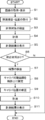
- 3 is a flowchart showing the operation of the ultrasonic diagnostic apparatus according to Embodiment 1 of the present invention. It is a schematic diagram which shows a mode that a user designates a measurement item and a measurement position. It is a figure which shows the example of a display of a measurement result. It is a figure which shows the example of the movable range of a caliper.
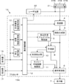
- FIG. 1 shows a configuration of an ultrasonic diagnostic apparatus 1 according to Embodiment 1 of the present invention.
- the ultrasonic diagnostic apparatus 1 includes an array transducer 2, and a transmission unit 3 and a reception unit 4 are connected to the array transducer 2.
- An image generation unit 5 is connected to the reception unit 4, and a display control unit 6 and a display unit 7 are sequentially connected to the image generation unit 5.
- a measurement unit 8 is connected to the image generation unit 5, and the measurement unit 8 is connected to the display control unit 6.
- a detection measurement algorithm setting unit 9 and a contour detection unit 10 are connected to the measurement unit 8, and a caliper movable range restriction unit 11 is connected to the contour detection unit 10.
- the caliper movable range restriction unit 11 is connected to the display control unit 6.
- the apparatus control unit 12 is connected to the transmission unit 3, the reception unit 4, the image generation unit 5, the display control unit 6, the measurement unit 8, the detection measurement algorithm setting unit 9, the contour detection unit 10, and the caliper movable range restriction unit 11.
- the apparatus control unit 12 is connected with a measurement item designation receiving unit 13, a position designation receiving unit 14, a correction receiving unit 15, an operation unit 16, and a storage unit 17. Further, the measurement item designation receiving unit 13, the position designation receiving unit 14, and the correction receiving unit 15 are each connected to the operation unit 16.
- the device control unit 12 and the storage unit 17 are connected so as to be able to exchange information in both directions.
- the array transducer 2 is included in the probe 18.
- the transmission unit 3, the reception unit 4, the image generation unit 5, the display control unit 6, the measurement unit 8, the detection measurement algorithm setting unit 9, the contour detection unit 10, the caliper movable range restriction unit 11, the device control unit 12, the measurement item A processor 19 is constituted by the designation receiving unit 13, the position designation receiving unit 14, and the correction receiving unit 15.
- the array transducer 2 of the probe 18 shown in FIG. 1 has a plurality of ultrasonic transducers arranged one-dimensionally or two-dimensionally. Each of these transducers transmits an ultrasonic wave according to a drive signal supplied from the transmission unit 3 and receives a reflected wave from the subject to output a reception signal.
- Each vibrator is, for example, a piezoelectric ceramic represented by PZT (Lead Zirconate Titanate), a polymer piezoelectric element represented by PVDF (Poly Vinylidene Di Fluoride) and PMN-PT (polyvinylidene fluoride).
- Electrodes are formed on both ends of a piezoelectric body made of a piezoelectric single crystal or the like typified by LeadesMagnesium Niobate-Lead Titanate: lead magnesium niobate-lead titanate solid solution).
- the transmission unit 3 of the processor 19 includes, for example, a plurality of pulse generators. From the plurality of transducers of the array transducer 2 based on the transmission delay pattern selected according to the control signal from the device control unit 12. Each drive signal is supplied to a plurality of transducers with the delay amount adjusted so that the transmitted ultrasonic waves form an ultrasonic beam.
- a pulsed or continuous wave voltage is applied to the electrodes of the transducers of the array transducer 2
- the piezoelectric body expands and contracts, and pulsed or continuous wave ultrasonic waves are generated from the respective transducers.
- An ultrasonic beam is formed from the synthesized wave of the ultrasonic waves.
- the transmitted ultrasonic beam is reflected by a target such as a part of the subject and propagates toward the array transducer 2 of the probe 18.
- the ultrasonic waves propagating toward the array transducer 2 in this way are received by the respective transducers constituting the array transducer 2.
- each transducer constituting the array transducer 2 expands and contracts by receiving propagating ultrasonic echoes to generate electrical signals, and outputs these electrical signals to the receiving unit 4.
- the reception unit 4 of the processor 19 processes the reception signal output from the array transducer 2 in accordance with the control signal from the device control unit 12. As shown in FIG. 2, the reception unit 4 has a configuration in which an amplification unit 20 and an AD (Analog / Digital) conversion unit 21 are connected in series.
- the amplifying unit 20 amplifies reception signals input from the respective elements constituting the array transducer 2 and transmits the amplified reception signals to the AD conversion unit 21.
- the AD conversion unit 21 converts the received signal transmitted from the amplification unit 20 into digitized data, and sends these data to the image generation unit 5 of the processor 19.
- the image generation unit 5 of the processor 19 has a configuration in which a signal processing unit 22, a DSC (Digital Scan Converter) 23, and an image processing unit 24 are connected in series.
- the signal processing unit 22 Based on the reception delay pattern selected according to the control signal from the device control unit 12, the signal processing unit 22 gives each element data according to the set sound speed and performs addition (phasing addition). Perform receive focus processing.
- receive focus processing By this reception focus processing, a sound ray signal in which the focus of the ultrasonic echo is narrowed is generated.
- the signal processing unit 22 performs an envelope detection process after correcting the attenuation caused by the propagation distance according to the depth of the position where the ultrasonic wave is reflected on the generated sound ray signal, A B-mode image signal that is tomographic image information related to the tissue in the subject is generated.
- the B-mode image signal generated in this way is output to the DSC 23.
- the DSC 23 raster-converts the B-mode image signal into an image signal in accordance with a normal television signal scanning method.
- the image processing unit 24 performs various necessary image processing such as brightness correction, gradation correction, sharpness correction, and color correction on the image data obtained in the DSC 23, and then displays the B-mode image signal as a display control unit. 6 and the measurement unit 8.
- the measuring unit 8 will be described in detail later.
- the operation unit 16 of the ultrasonic diagnostic apparatus 1 is for a user to perform an input operation, and can be configured to include a keyboard, a mouse, a trackball, a touch pad, a touch panel, and the like.
- the measurement item designation accepting unit 13 of the processor 19 accepts designation of measurement items related to the measurement target from the user via the operation unit 16.
- a measurement item related to a measurement target is an item that can indicate at least one of the measurement target and measurement content.
- the measurement target includes the name of a target site such as an organ, a tumor, a cyst, and a lesion such as bleeding. It can include items related to names and abnormalities.
- the measurement content can include the length and area of the measurement target. Therefore, for example, the measurement item is only the name of the measurement target, only the name of the lesion, only the item related to the abnormality, the name of the measurement target and its measurement content, the name of the lesion and its measurement content, the item about the abnormality and its measurement content Any one can be included.
- the measurement item includes only the measurement target, for example, the measurement content such as whether the length is measured or the size is measured with respect to the measurement target specified by the user via the operation unit 16 is associated. It is done. Specifically, for example, a table in which the measurement target and the measurement content are associated with each other is stored in the storage unit 17 or an external memory (not shown), and the measurement content corresponding to the measurement target is selected based on this table.
- the position designation receiving unit 14 of the processor 19 receives the designation of the position of the measurement target on the ultrasonic image displayed on the display unit 7 from the user via the operation unit 16.
- the detection measurement algorithm setting unit 9 of the processor 19 sets an algorithm for detecting the measurement target and an algorithm for measuring the measurement target based on the measurement item received by the measurement item designation receiving unit 13 from the user via the operation unit 16. .
- an algorithm for detecting a measurement target from an image differs depending on the type of the measurement target such as an organ and a lesion.
- an algorithm for measuring the measurement target on the image differs depending on the measurement contents such as the measurement of the length of the measurement target and the measurement of the area.
- the detection measurement algorithm setting unit 9 stores an algorithm corresponding to each measurement target and an algorithm corresponding to each measurement content as an association table, and the measurement item designation receiving unit 13 receives a measurement item from the user via the operation unit 16. Is received, the detection measurement algorithm is set with reference to the association table.
- the algorithm defines calculation means for achieving the objects such as detection and measurement, and is implemented in the apparatus as a software program, for example, by a CPU (Central Processing Unit). Is to be executed.
- a CPU Central Processing Unit
- typical pattern data is stored in advance as a template, and the similarity to the pattern data is calculated while searching the template with the template.
- simple template matching for example, Csurka et al .: Visual Categorization with Bags of Keypoints, Proc. Of ECCV Workshop on Statistical Learning in Computer Vision, pp.
- the measurement unit 8 detects the measurement target by scanning the scan range set on the ultrasonic image based on the detection measurement algorithm.
- the measurement unit 8 arranges a caliper for performing measurement of the measurement target on the ultrasonic image based on the detection measurement algorithm, and performs measurement on the measurement target based on the arranged caliper. Measure.
- the correction reception unit 15 of the processor 19 receives correction of the position of the caliper arranged on the ultrasonic image by the measurement unit 8.
- the correction of the position of the caliper is performed by the user via the operation unit 16.
- the contour detection unit 10 of the processor 19 detects the contour of the measurement target detected by the measurement unit 8 by performing image analysis on the ultrasonic image.
- the contour detection unit 10 can extract the contour of the measurement target using a general image recognition method using deep learning or the like, a machine learning method, or the like.
- the caliper movable range restriction unit 11 of the processor 19 detects the caliper movable range by the contour detection unit 10 when the position of the caliper arranged on the ultrasonic image is corrected by the user via the operation unit 16. Limit on the contour.
- the device control unit 12 of the processor 19 controls each unit of the ultrasonic diagnostic apparatus 1 based on a program stored in advance in the storage unit 17 and the user's operation via the operation unit 16.
- the display control unit 6 of the processor 19 is limited by the caliper movable range limiting unit 11 under the apparatus control unit 12, the B-mode image generated by the image generation unit 5, the measurement result of the caliper calculated by the measurement unit 8, and the like.
- a predetermined process is performed on the movable range of the caliper, and the display unit 7 displays the B-mode image, the measurement result of the caliper, the movable range of the caliper, and the like.
- the display unit 7 of the ultrasonic diagnostic apparatus 1 displays an image or the like under the control of the display control unit 6 and includes a display device such as an LCD (Liquid Crystal Display).
- the storage unit 17 stores an operation program or the like of the ultrasonic diagnostic apparatus 1, and includes an HDD (Hard Disc Drive), an SSD (Solid State Drive), an FD (Flexible Disc), MO disc (Magneto-Optical disc), MT (Magnetic Tape), RAM (Random Access Memory), CD (Compact Disc), DVD (Digital Versatile Disc: Digital Versatile Disc)
- a recording medium such as a disk), an SD card (Secure Digital card), a USB memory (Universal Serial Bus memory), a server, or the like can be used.
- the processor 19 having the designation accepting unit 13, the position designation accepting unit 14 and the modification accepting unit 15 includes a CPU and a control program for causing the CPU to perform various processes, and is configured using a digital circuit. May be. Further, these transmission unit 3, reception unit 4, image generation unit 5, display control unit 6, measurement unit 8, detection measurement algorithm setting unit 9, contour detection unit 10, caliper movable range restriction unit 11, device control unit 12, The measurement item designation receiving unit 13, the position designation receiving unit 14, and the correction receiving unit 15 may be configured to be partially or wholly integrated into one CPU.
- step S ⁇ b> 1 an ultrasonic image is acquired, and the acquired ultrasonic image is displayed on the display unit 7.
- this ultrasonic image an image captured on the spot using the probe 18 can be used. It is also possible to use past ultrasonic images stored in an image memory (not shown).
- step S2 the measurement item designated by the user via the operation unit 16 and the measurement position on the ultrasonic image are received by the measurement item designation receiving unit 13 and the position designation receiving unit 14, respectively.
- a measurement item for example, as shown in FIG. 5, a list M of measurement items is displayed on the display unit 7, and one of a plurality of measurement items displayed in the list M is displayed. Can be selected by the user via the operation unit 16. In the example shown in FIG. 5, the size of the gallbladder is selected as the measurement item.
- the measurement item designation receiving unit 13 receives the measurement item designated by the user in this way.
- the detection measurement algorithm setting unit 9 sets a detection measurement algorithm corresponding to the measurement item.
- the user when specifying the measurement position on the ultrasonic image, the user specifies one point in the region representing the measurement target.
- the display unit 7 is a display with a touch panel and the operation unit 16 is configured by the touch panel of the display unit 7, as shown in FIG. 5, the user represents the gallbladder G on the ultrasonic image.
- the measurement position can be specified by touching one point in the area.
- the position designation receiving unit 14 receives the measurement position designated by the user in this way.
- step S ⁇ b> 3 the measurement unit 8 sets a scan range on the ultrasonic image based on the detection measurement algorithm set by the detection measurement algorithm setting unit 9, and scans the scan range, thereby selecting a measurement target. To detect.
- step S4 the measurement unit 8 arranges a caliper for measuring the measurement object detected in step S3 on the ultrasonic image, and performs measurement on the measurement object using the arranged caliper. At this time, the measurement unit 8 measures the measurement target based on the rule determined according to the measurement item by the detection measurement algorithm.
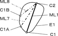
- the measurement unit 8 measures the measurement line with the two calipers C1 and C2 arranged on the inner wall of the region representing the gallbladder G as end points, as shown in FIG. The length of ML1 is measured.
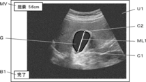
- step S5 the measurement unit 8 displays the measurement result of the caliper or the like obtained in step S4 on the display unit 7.
- the measurement unit 8 can display calipers C1 and C2, the measurement line ML1, and the measurement value MV as measurement results together with the ultrasonic image U1.
- step S6 it is determined whether or not there is a correction request regarding the position of the caliper arranged on the ultrasonic image. For example, as shown in FIG. 6, when the completion button B1 for completing the measurement for the measurement object is displayed together with the ultrasonic image U1, and the completion button B1 is pressed by the user via the operation unit 16, the caliper It is determined that there is no request for correction of the positions of C1 and C2. In this case, the operation of the ultrasonic diagnostic apparatus 1 ends.
- step S6 If it is determined in step S6 that there is a correction request regarding the position of the caliper, the process proceeds to step S7. For example, when the user starts changing the position of the caliper C1 or C2 without pressing the completion button B1 shown in FIG. 6, it is determined that there is a request for correction of the measurement point.
- step S7 the contour detecting unit 10 detects the contour of the measurement target detected by the measuring unit 8 by performing image analysis on the ultrasonic image acquired in step S1.
- the contour detection unit 10 sets, for example, a detection region including the measurement target detected in step S3, and performs image analysis on the ultrasonic image in the detection region to thereby detect the contour of the measurement target. Can be detected.
- the contour detection unit 10 detects, for example, the inner wall of the gallbladder G as the contour E1 of the gallbladder G as shown in FIG.
- step S8 the caliper movable range restriction unit 11 restricts the movable range of the caliper arranged on the ultrasonic image in step S4 to the contour detected in step S7.
- the caliper movable range restriction unit 11 sets the movable range of the calipers C1 and C2 to the contour of the region representing the gallbladder G on the ultrasound image as shown in FIG. Restrict to E1.
- step S9 when the position of the caliper is corrected by the user via the operation unit 16, the correction receiving unit 15 receives the correction of the caliper by the user.
- the correction receiving unit 15 It is determined that the correction of C2 is completed, and the correction of the caliper C1 or C2 by the user is accepted.
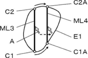
- the user can correct the position of the caliper by dragging the caliper via the operation unit 16. For example, as shown in FIG. 8, when the user operates the cursor A via the operation unit 16, the caliper C1 closer to the cursor A among the calipers C1 and C2 is dragged and moved. At this time, since the movable range of the caliper C1 is limited to the contour E1 to be measured, the caliper C1 is connected to the line segment connecting the caliper C2 not dragged by the cursor A to the point where the cursor A is dragged. The intersection with the contour E1 is moved.
- the movable range of the cursor A is limited on the contour E1 to be measured, so that the caliper C1 or C2 moves on the contour E1. You can also.
- the operation unit 16 is constituted by a touch panel, instead of using the cursor A, as shown in FIG. 5, the caliper C1 or C2 is touched by the user's finger F and dragged. The caliper C1 or C2 may be moved.
- the measurement unit 8 measures the measurement target based on the caliper corrected in step S9. For example, when the measurement line ML1 is corrected to the measurement line ML2 by correcting the position of the caliper C1 to the position of the caliper C1A as shown in FIG. 8 in step S9, the measurement unit 8 performs a new measurement. The length of the line ML2 is measured.
- the measurement unit 8 displays the measurement result such as the caliper corrected in step S9 and the measurement value obtained in step S10 on the display unit 7. Thereby, the operation of the ultrasonic diagnostic apparatus 1 is completed.
- the ultrasonic diagnostic apparatus 1 of the first embodiment of the present invention when the user corrects the caliper automatically set by the measuring unit 8 in step S4 via the operation unit 16, the caliper Since the movable range is limited on the contour of the measurement target, the user can easily and accurately set the caliper position automatically set so that the caliper is placed at an appropriate position for measuring the measurement target. Can be corrected manually.
- Modification 1 In the first embodiment, an example is shown in which one of the calipers C1 and C2 is dragged with the cursor A to correct the position of the caliper C1, but the caliper correction method is not limited to this.
- the positions of the calipers C1 and C2 can be moved by moving the measurement line ML3 using the cursor A while keeping the inclination of the measurement line ML3 in a certain direction.
- the calipers C1 and C2 follow the movement of the measurement line ML3 and move on the contour E1 to be measured so as to form a measurement line along the same direction as the measurement line ML3.
- FIG. 9 the positions of the calipers C1 and C2 can be moved by moving the measurement line ML3 using the cursor A while keeping the inclination of the measurement line ML3 in a certain direction.
- the calipers C1 and C2 follow the movement of the measurement line ML3 and move on the contour E1 to be measured so as to form a measurement line along the same direction as the
- the measurement lines ML3 are corrected to the measurement lines ML4 by correcting the positions of the calipers C1 and C2 to the positions of the calipers C1A and C2A, respectively.
- the user can easily and accurately make corrections.
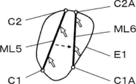
- Modification 2 Further, for example, when the operation unit 16 is configured by a touch panel, as shown in FIG. 10, two points in the region representing the measurement target on the ultrasonic image are dragged while being tapped by the user's finger F or the like.
- the calipers C1 and C2 can be moved so as to form a measurement line passing through two points tapped by the user.
- two points on the measurement line ML5 are dragged while being tapped by the user, and the calipers C1 and C2 are moved to the measurement object outline E1 to be corrected to calipers C1A and C2A.
- a measurement line ML6 is obtained. Thereby, the user can correct calipers C1 and C2 more intuitively and easily.
- the caliper movable range restriction unit 11 calculates a recommendation level for correcting the position of the caliper at each point on the contour E1 to be measured, and displays a measurement line connected to the caliper according to the calculated recommendation level.
- the method can be changed.
- a recommendation degree at each point of the contour E1 to be measured for example, an index representing the edge likeness of the ultrasonic image at the contour E1 can be used.
- the recommendation degree can be calculated by image analysis using the contrast between the target point on the ultrasonic image and the surrounding points.
- a value calculated according to the difference between the length of the measurement line connected to the caliper and the maximum diameter of the contour E1 can be used as the recommendation degree.
- a value calculated according to an angle difference between a measurement line connected to the caliper and the inertial spindle to be measured can be used as the recommendation degree.
- the caliper movable range restriction unit 11 sets the movable ranges of the calipers C1 and C2 on the contour E1 in the range R1 where the calculated recommendation level is lower than the set reference value. Can be lifted.
- the caliper C1 when the caliper C1 is dragged by the cursor A, the caliper C1 moves on the contour E1, but can be freely limited to a range R1 lower than the reference value for which the recommended degree is set. Can move.
- the caliper C1 is dragged within the range R1 and moved to the position of the caliper C1A. Accordingly, the user corrects the calipers C1 and C2 more accurately and easily because the user corrects the calipers C1 and C2 while grasping the position having the recommended degree larger than a certain value on the contour E1 to be measured. be able to.
- the caliper movable range restriction unit 11 determines the color, thickness, and line type of the measurement lines connected by the calipers C1 and C2 according to the recommendation level of the position on the measurement target contour E1. At least one of can be changed.
- the measurement line ML1 is corrected to the measurement line ML7 by correcting the caliper C1 to the position of the caliper C1A, and the measurement line ML1 is adjusted to the measurement line by correcting the caliper C1 to the position of the caliper C1B.
- the measurement lines ML1, ML7, and ML8 are modified to ML8, and display modes such as color, thickness, line type, and the like are different depending on the recommended degree of the position on the obtained contour E1.
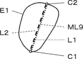
- the caliper movable range restriction unit 11 calculates a plurality of types of recommendation degrees calculated by a plurality of calculation methods, and configures the measurement line by a plurality of lines having display modes corresponding to the plurality of types of recommendation degrees. be able to.
- the caliper movable range restriction unit 11 includes the measurement line ML9 composed of line segments L1 and L2 having different display modes such as color, thickness, line type, etc., according to two types of recommendation. can do.
- the user can easily grasp the recommended degree of the position on the contour E1.
- the caliper movable range restriction unit 11 learns the correction of the position of the caliper by the user via the operation unit 16, and based on the learning result, further moves the caliper movable range to a part on the contour E1 to be measured. Can be limited. For example, as shown in FIG. 14, the caliper movable range limiting unit 11 learns the correction results of the calipers C1 and C2 by the user, and determines the caliper C1 movable range from the position of the caliper C1 set by the measuring unit 8.
- the range of the caliper C2 is further restricted within a range R2 having a certain length on the left and right, and the movable range of the caliper C2 is further restricted within a range R3 having a certain length on the left and right from the position of the caliper C2 set by the measuring unit 8. .
- the movable range of the calipers C1 and C2 is limited in accordance with the tendency of the position to be corrected by the user, so that the user can correct the calipers C1 and C2 more easily.
- Modification 6 when measuring the diameter of the measurement target using an ultrasonic image in which the contour of the measurement target becomes a closed curve, depending on the user, when placing the measurement line so that the diameter of the measurement target is maximum, In some cases, a measurement line is arranged along the inertial main axis to be measured. As described above, the measurement rule for the next and subsequent times can be set for a measurement target having a plurality of measurement rules by the user according to the correction result of the user.
- the measurement unit 8 calculates measurement values for both the measurement line ML10 where the inner diameter of the kidney K is maximum and the measurement line ML11 along the inertial main axis of the kidney K.
- One of the two measurement lines ML10 and ML11 is displayed on the display unit 7.
- the detection measurement algorithm setting unit 9 Determines whether the new measurement line set by correcting the caliper C3, C4, or C5 by the user is closer to the measurement lines ML10 and ML11.
- the detection measurement algorithm setting unit 9 performs measurement that maximizes the inner diameter of the kidney K in the subsequent measurement. If a new measurement line is close to the measurement line ML11, the measurement line is set along the inertial main axis of the kidney K in the subsequent measurement. As described above, by setting the measurement rule for the measurement target according to the correction result of the user, it is possible to perform measurement in accordance with the measurement rule used by the user in the subsequent measurement.
- Modification 7 In the first embodiment, an example is described in which the contour of the measurement target is configured by a closed curve. However, the present invention can be applied even when the contour of the measurement target is configured by a plurality of curves instead of the closed curve. Can be applied.
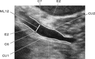
- the contour E2 of the measurement target has two curves CU1 and CU2. And a measurement line ML12 having a caliper C6 arranged on the curve CU1 and a caliper C7 arranged on the curve CU2 as end points.
- the caliper movable range limiting unit 11 can limit the movable range of the caliper C6 on the curve CU1, and can limit the movable range of the caliper C7 on the curve CU2.
- the caliper C6 closer to the cursor A among the calipers C6 and C7 is dragged and moved.
- the caliper C6 is not dragged by the cursor A to the point where the cursor A is dragged.
- the intersection of the line CU1 and the curve CU1 is moved.
- the measurement line ML13 is corrected to the measurement line ML14 by correcting the position of the caliper C6 to the position of the caliper C6A.
- the caliper movable range is limited
- the unit 11 calculates an approximate straight line of the measurement target edge around the caliper, and limits the movable range of the caliper so that the measurement line connected to the caliper moves while facing a direction perpendicular to the approximate straight line. be able to.
- the caliper movable range restriction unit 11 has two calipers C6 and C7 positioned at both ends of the measurement line ML15 based on the contour of the measurement target detected by the contour detection unit 10. Two parallel approximate lines FL1 and FL2 of the measurement target edge in the periphery are calculated, and the movable ranges of the calipers C6 and C7 are limited to the approximate lines FL1 and FL2, respectively.
- the measurement line ML15 is dragged by the cursor A and moves while facing the direction perpendicular to the approximate lines FL1 and FL2, that is, while being substantially orthogonal to the center line CL to be measured.
- the calipers C6 and C7 move following the measurement line ML15.
- the caliper movable range limiting unit 11 can calculate two approximate straight lines FL3 and FL4 inclined at different angles as the movable ranges of the calipers C8 and C9.
- the measurement line ML16 having the end points on the calipers C8 and C9 arranged on the approximate lines FL3 and FL4 is dragged by the cursor A and points in a direction perpendicular to the average angle of the approximate lines FL3 and FL4. As it is, that is, it moves while being substantially orthogonal to the center line CL to be measured.
- the calipers C8 and C9 move following the measurement line ML16. In this way, by limiting the movable range of the calipers C6 to C9, the user can more easily correct the positions of the calipers C6 to C9.
- the contour of the measurement target is detected by the contour detection unit 10 after the caliper is arranged on the ultrasonic image by the measurement unit 8, but after the contour of the measurement target is detected, A caliper may be arranged on the ultrasonic image based on the detected contour. For example, by including the contour detection unit 10 in the measurement unit 8, when the measurement unit 8 detects the measurement target in step S3, the contour of the measurement target is detected, and a caliper is arranged on the detected contour. be able to. For example, when the measurement target is the gallbladder G, the measurement unit 8 detects the inner wall of the gallbladder G as an outline E1 of the gallbladder G and places calipers C1 and C2 on the outline E1 as shown in FIG.
- the caliper movable range restriction unit 11 detects the contour of the measurement target detected in step S3 in step S8.
- the range of movement of the caliper is limited.
- Embodiment 2 In the first embodiment, the ultrasonic diagnostic apparatus is described. However, the present invention can also be applied to an acoustic diagnostic apparatus other than the ultrasonic diagnostic apparatus, such as a photoacoustic diagnostic apparatus.
- FIG. 19 shows the configuration of the photoacoustic wave diagnostic apparatus 1A according to the second embodiment. This photoacoustic wave diagnostic apparatus 1A includes the probe 31 instead of the probe 18 and the laser light source 32 instead of the transmitter 3 in the ultrasonic diagnostic apparatus 1 of the first embodiment shown in FIG. .
- the probe 31 has an array transducer 31A similar to the array transducer 2 of the ultrasonic diagnostic apparatus 1 shown in FIG. 1 and a pair of laser beam irradiation units 31B arranged at both ends of the array transducer 31A.
- the array transducer 31 ⁇ / b> A is connected to the receiving unit 4.
- the pair of laser light irradiation units 31 ⁇ / b> B is connected to the laser light source 32, and the laser light source 32 is connected to the apparatus control unit 12.
- the position designation receiving unit 14 and the correction receiving unit 15 constitute a processor 19A.
- the laser light source 32 of the photoacoustic wave diagnostic apparatus 1 ⁇ / b> A emits pulsed laser light under the control of the apparatus control unit 12.
- the laser light source 32 includes a laser rod 33, an excitation light source 34, a mirror 35, a mirror 36, and a Q switch 37.
- the laser rod 33 is a laser medium.
- an alexandrite crystal, an Nd: YAG crystal, or the like can be used.
- the excitation light source 34 is a light source that irradiates the laser rod 33 with excitation light.
- a light source such as a flash lamp and a laser diode can be used as the excitation light source 34.
- the mirrors 35 and 36 are opposed to each other with the laser rod 33 interposed therebetween, and the mirrors 35 and 36 constitute an optical resonator.
- the mirror 36 is on the output side.
- a Q switch 37 is inserted in the optical resonator, and the Q switch 37 rapidly changes the insertion loss in the optical resonator from the large insertion loss state to the small insertion loss state. Obtainable.
- the pulse laser beam emitted from the output-side mirror 36 of the laser light source 32 is guided to the laser beam irradiation unit 31B of the probe 31 through a light guide member or the like (not shown).
- the laser beam irradiation units 31B of the probe 31 are arranged at both ends of the array transducer 31A, are in contact with the body surface of the subject, and are pulse lasers guided from the laser light source 32 through a light guide member (not shown). Light is irradiated into the subject.
- the pulsed laser light irradiated into the subject in this way is absorbed as thermal energy by a biological substance such as hemoglobin contained in the subject, and the biological substance that has absorbed the pulsed laser light expands and contracts. As a result, a photoacoustic wave is emitted.
- the array transducer 31A of the probe 31 has the same configuration as that of the array transducer 2 shown in FIG. 1, but a pulse laser beam is irradiated from the laser light source 32 into the subject via the laser beam irradiation unit 31B. Is received, and a photoacoustic wave reception signal is output to the receiving unit 4. The photoacoustic wave reception signal thus obtained is sent to the image generation unit 5 in the same manner as the reception signal based on the ultrasonic echo in the first embodiment, and a photoacoustic image is generated by the image generation unit 5. The The photoacoustic image generated in this manner is displayed on the display unit 7 via the display control unit 6 and is sent to the measurement unit 8 to be used for measurement of the measurement target.
- the contour detection unit 10 detects the contour of the measurement target detected by the measurement unit 8 by performing image analysis on the photoacoustic image.
- the caliper movable range restriction unit 11 is a measurement in which, in the photoacoustic image, the caliper movable range is detected by the contour detection unit 10 when the caliper set by the measurement unit 8 is corrected by the user via the operation unit 16. Restrict to the contour of the object.
- the measurement unit 8 measures the measurement target based on the corrected caliper, and performs measurement. The result is displayed on the display unit 7.
- the present invention is also applied to an acoustic wave diagnostic apparatus such as the photoacoustic wave diagnostic apparatus 1A.
Abstract
An acoustic wave diagnostic device (1) is provided with: a display unit (7); an operating unit (16); a measurement item designation receiving unit (13) for receiving designation of a measurement item; a detection measurement algorithm setting unit (9) for setting a detection measurement algorithm in accordance with a measurement item; a position designation receiving unit (14) for receiving designation of a measurement position; a measurement unit (8) for detecting a measurement object by the measurement position and the detection measurement algorithm, setting a caliper on the measurement object, and performing measurement; a contour detection unit (10) for detecting a contour of the measurement object; a caliper movable range limiting unit (11) for limiting the movable range of the caliper on the contour of the measurement object; and a modification receiving unit (15) for receiving modification of the caliper through the operating unit (16); the measurement unit (8) performing measurement through use of the modified caliper.
Description
本発明は、音響波診断装置および音響波診断装置の制御方法に係り、特に、音響波画像上における計測対象の検出および計測を行う音響波診断装置および音響波診断装置の制御方法に関する。
The present invention relates to an acoustic wave diagnostic device and an acoustic wave diagnostic device control method, and more particularly, to an acoustic wave diagnostic device that performs detection and measurement of a measurement target on an acoustic wave image and a control method for the acoustic wave diagnostic device.
近年、医用音響波診断装置においては、取得した音響波画像内に含まれる様々な臓器や病変等に対して、長さ、大きさおよび面積等の計測を行う計測機能を有することが一般的になっている。計測対象を計測するためには、通常、ユーザがトラックパッド、トラックボール、マウス等の座標を入力する入力装置を用いてキャリパすなわちカーソルを操作し、表示画像上に計測点や関心領域等の設定をすることが行われている。このように、ユーザによる手動の操作がなされる場合には、ユーザの経験および熟練度等が影響するため、操作を自動化する種々の試みがなされている。
In recent years, medical acoustic diagnostic apparatuses generally have a measurement function for measuring the length, size, area, and the like of various organs and lesions included in an acquired acoustic wave image. It has become. In order to measure a measurement target, a user usually operates a caliper, that is, a cursor using an input device for inputting coordinates such as a trackpad, a trackball, and a mouse, and sets a measurement point, a region of interest, etc. on a display image. Has been done. As described above, when a manual operation is performed by the user, the user's experience, skill level, and the like are affected. Therefore, various attempts have been made to automate the operation.
例えば、特許文献1には、操作部を介してユーザから計測対象に対するボディマークが選択されると、その計測対象に最適な画像モード、画質設定、計測モードおよび計測項目が自動的に設定される超音波診断装置が開示されている。特許文献1では、超音波画像に対し、操作部を介してユーザから入力された計測点の位置、数およびその順序により、計測対象に対する計測が行われ、その計測結果が表示部に表示される。
For example, in Patent Document 1, when a body mark for a measurement target is selected from the user via the operation unit, an image mode, image quality setting, measurement mode, and measurement item that are optimal for the measurement target are automatically set. An ultrasonic diagnostic apparatus is disclosed. In Patent Document 1, measurement is performed on a measurement target based on the position, number, and order of measurement points input from a user via an operation unit on an ultrasonic image, and the measurement result is displayed on a display unit. .
このように、特許文献1および2に開示されている超音波診断装置においては、操作部を介して計測点および指定点を手動で指定する必要があるため、計測に多大の手間がかかってしまう。そこで、計測対象が存在する超音波画像上のおよその位置をユーザが指定するだけで、その周辺を自動的に探索して計測対象を検出し、計測を行うことが望まれている。
しかしながら、キャリパを配置する位置および計測ルールは、ユーザによって異なることがあり、自動で設定されたキャリパの位置に対して手動で修正したい場合がある。そこで、キャリパの設定を手動モードに切り替えて、ユーザが正しいと考える位置まで手動でキャリパを移動させようとすると、操作の手間が大きく、特に、小型端末の場合には、より精密な操作が要求されるため、ユーザの負担および操作時間が増大するという問題がある。 As described above, in the ultrasonic diagnostic apparatuses disclosed inPatent Documents 1 and 2, it is necessary to manually specify the measurement point and the designated point via the operation unit. . Therefore, it is desired that the user designates an approximate position on the ultrasonic image where the measurement target is present, and automatically searches the periphery to detect the measurement target and perform measurement.
However, the position where the caliper is arranged and the measurement rule may differ depending on the user, and there is a case where it is desired to manually correct the caliper position set automatically. Therefore, switching the caliper setting to manual mode and manually moving the caliper to the position that the user thinks is correct requires a lot of work, especially in the case of a small terminal, requiring more precise operation. Therefore, there is a problem that the burden on the user and the operation time increase.
しかしながら、キャリパを配置する位置および計測ルールは、ユーザによって異なることがあり、自動で設定されたキャリパの位置に対して手動で修正したい場合がある。そこで、キャリパの設定を手動モードに切り替えて、ユーザが正しいと考える位置まで手動でキャリパを移動させようとすると、操作の手間が大きく、特に、小型端末の場合には、より精密な操作が要求されるため、ユーザの負担および操作時間が増大するという問題がある。 As described above, in the ultrasonic diagnostic apparatuses disclosed in
However, the position where the caliper is arranged and the measurement rule may differ depending on the user, and there is a case where it is desired to manually correct the caliper position set automatically. Therefore, switching the caliper setting to manual mode and manually moving the caliper to the position that the user thinks is correct requires a lot of work, especially in the case of a small terminal, requiring more precise operation. Therefore, there is a problem that the burden on the user and the operation time increase.
本発明は、このような従来の問題点を解消するためになされたものであり、自動で設定されたキャリパの位置を容易に且つ正確に手動で修正することができる音響波診断装置および音響波診断装置の制御方法を提供することを目的とする。
The present invention has been made to solve such a conventional problem, and an acoustic wave diagnostic apparatus and acoustic wave capable of easily and accurately manually correcting a position of a caliper set automatically. An object of the present invention is to provide a method for controlling a diagnostic apparatus.
上記目的を達成するために、本発明の音響波診断装置は、取得した音響波画像を表示する表示部と、ユーザが入力操作を行うための操作部と、操作部を介して計測対象に関連する計測項目の指定を受け付ける計測項目指定受付部と、計測項目指定受付部により受け付けられた計測項目に基づいて検出計測アルゴリズムを設定する検出計測アルゴリズム設定部と、操作部を介して表示部に表示された音響波画像上の計測対象の位置の指定を受け付ける位置指定受付部と、位置指定受付部により受け付けられた計測対象の位置と検出計測アルゴリズム設定部により設定された検出計測アルゴリズムとに基づいて、計測対象を検出し、検出された計測対象に対してキャリパを設定して計測を行い、且つ計測結果を表示部に表示させる計測部と、音響波画像上の計測対象の輪郭を検出する輪郭検出部と、操作部を介したキャリパの位置の修正依頼に応じて、キャリパの可動範囲を輪郭検出部により検出された輪郭上に制限するキャリパ可動範囲制限部と、操作部を介してなされたキャリパの位置の修正を受け付ける修正受付部とを備え、計測部は、修正受付部により受け付けられたキャリパの位置の修正に基づいて計測対象に対する計測を行って計測結果を表示部に表示させることを特徴とする。
In order to achieve the above object, an acoustic wave diagnostic apparatus according to the present invention relates to a display unit that displays an acquired acoustic wave image, an operation unit for a user to perform an input operation, and a measurement target via the operation unit. A measurement item specification receiving unit that receives specification of a measurement item to be performed, a detection measurement algorithm setting unit that sets a detection measurement algorithm based on the measurement item received by the measurement item specification receiving unit, and a display unit that displays the operation unit Based on a position designation accepting unit that accepts designation of a position of a measurement target on the acoustic wave image that has been received, a position of the measurement target accepted by the position designation accepting unit, and a detection measurement algorithm set by the detection measurement algorithm setting unit A measurement unit that detects a measurement target, sets a caliper to the detected measurement target, performs measurement, and displays a measurement result on a display unit; and a sound A contour detection unit that detects the contour of the measurement target on the wave image, and a caliper movable that limits the movable range of the caliper to the contour detected by the contour detection unit in response to a request for correction of the caliper position via the operation unit. A range limiting unit and a correction receiving unit that receives correction of the caliper position made via the operation unit, and the measurement unit performs measurement on the measurement target based on the correction of the caliper position received by the correction receiving unit. And the measurement result is displayed on the display unit.
もしくは、キャリパ可動範囲制限部は、キャリパに接続された計測線が定められた方向を向いたまま移動するようにキャリパの可動範囲を制限することもできる。
もしくは、キャリパ可動範囲制限部は、キャリパの周辺における計測対象のエッジの近似直線を算出し、キャリパに接続された計測線が近似直線に対して垂直な方向を向いたまま移動するようにキャリパの可動範囲を制限することもできる。
もしくは、キャリパ可動範囲制限部は、計測線の両端に位置する2つのキャリパのそれぞれの周辺における計測対象のエッジの2本の近似直線を算出し、計測線が2本の近似直線の平均の角度に対して垂直な方向を向いたまま移動するようにキャリパの可動範囲を制限することもできる。 Alternatively, the caliper movable range limiting unit can limit the movable range of the caliper so that the measurement line connected to the caliper moves while facing a predetermined direction.
Alternatively, the caliper movable range limiter calculates an approximate straight line of the measurement target edge around the caliper, and moves the caliper so that the measurement line connected to the caliper moves in a direction perpendicular to the approximate straight line. The movable range can also be limited.
Alternatively, the caliper movable range limiting unit calculates two approximate lines of the measurement target edge around each of the two calipers located at both ends of the measurement line, and the measurement line has an average angle of the two approximate lines. It is also possible to limit the movable range of the caliper so as to move while facing the direction perpendicular to the direction.
また、キャリパ可動範囲制限部は、輪郭上の各点におけるキャリパの位置修正の推奨度を算出し、算出された推奨度に応じてキャリパに接続される計測線の表示方式を変化させることができる。
より具体的には、キャリパ可動範囲制限部は、計測対象のエッジらしさに応じて推奨度を算出することができる。 In addition, the caliper movable range restriction unit can calculate the recommended degree of caliper position correction at each point on the contour, and can change the display method of the measurement line connected to the caliper according to the calculated recommended degree. .
More specifically, the caliper movable range restriction unit can calculate the recommendation degree according to the edge-likeness of the measurement target.
もしくは、キャリパ可動範囲制限部は、キャリパに接続される計測線の長さと輪郭の最大径との差分に応じて推奨度を算出することもできる。
もしくは、キャリパ可動範囲制限部は、キャリパに接続される計測線と計測対象の慣性主軸との角度差に応じて推奨度を算出することもできる。 Alternatively, the caliper movable range restriction unit can also calculate the recommendation degree according to the difference between the length of the measurement line connected to the caliper and the maximum diameter of the contour.
Alternatively, the caliper movable range restriction unit can also calculate the recommended degree according to the angle difference between the measurement line connected to the caliper and the inertial spindle to be measured.
また、キャリパ可動範囲制限部は、推奨度に応じて計測線の色、太さ、線種の少なくとも1つを変化させることができる。
また、キャリパ可動範囲制限部は、算出された推奨度が定められた基準値より低い位置では、キャリパの可動範囲を輪郭上に制限することを解除することができる。 In addition, the caliper movable range limiting unit can change at least one of the color, thickness, and line type of the measurement line according to the recommendation level.
In addition, the caliper movable range restriction unit can release the restriction of the caliper movable range on the contour at a position where the calculated recommendation level is lower than the predetermined reference value.
また、キャリパ可動範囲制限部は、ユーザによるキャリパの位置の修正を学習し、学習の結果に基づいて、キャリパの可動範囲を輪郭上の一部にさらに制限することができる。
また、音響波画像は、超音波画像または光音響画像であることが好ましい。 Further, the caliper movable range restriction unit can learn the correction of the position of the caliper by the user and can further restrict the movable range of the caliper to a part on the contour based on the learning result.
The acoustic wave image is preferably an ultrasonic image or a photoacoustic image.
本発明の音響波診断装置の制御方法は、取得した音響波画像を表示し、ユーザから計測対象に関連する計測項目の指定を受け付け、受け付けられた計測項目に基づいて検出計測アルゴリズムを設定し、ユーザから表示された音響波画像上の計測対象の位置の指定を受け付け、受け付けられた計測対象の位置と設定された検出計測アルゴリズムとに基づいて、計測対象を検出し、検出された計測対象に対してキャリパを設定して計測を行い、且つ計測結果を表示し、音響波画像上の計測対象の輪郭を検出し、ユーザからのキャリパの位置の修正依頼に応じて、キャリパの可動範囲を検出された輪郭上に制限し、ユーザからのキャリパの位置の修正を受け付け、受け付けられたキャリパの位置の修正に基づいて計測対象に対する計測を行って計測結果を表示することを特徴とする。
The control method of the acoustic wave diagnostic device of the present invention displays the acquired acoustic wave image, accepts designation of measurement items related to the measurement target from the user, sets a detection measurement algorithm based on the accepted measurement items, The measurement target position on the acoustic wave image displayed by the user is received, and the measurement target is detected based on the received measurement target position and the set detection measurement algorithm. The caliper is set for measurement, the measurement result is displayed, the contour of the measurement target on the acoustic wave image is detected, and the movable range of the caliper is detected in response to a request for correction of the caliper position from the user. The correction is made on the contour, the correction of the caliper position from the user is accepted, and the measurement target is measured based on the received correction of the caliper position. Results and displaying the.
本発明によれば、音響波画像上の計測対象の輪郭を検出する輪郭検出部と、操作部を介したキャリパの位置の修正依頼に応じて、キャリパの可動範囲を輪郭検出部により検出された輪郭上に制限するキャリパ可動範囲制限部と、操作部を介してなされたキャリパの位置の修正を受け付ける修正受付部とを備え、計測部は、修正受付部により受け付けられたキャリパの位置の修正に基づいて計測対象に対する計測を行って計測結果を表示部に表示させるため、自動で設定されたキャリパの位置を容易に且つ正確に手動で修正することができる。
According to the present invention, the contour detection unit that detects the contour of the measurement target on the acoustic wave image and the caliper movable range detected by the contour detection unit in response to a request to correct the position of the caliper via the operation unit. A caliper movable range limiting unit that restricts on the contour and a correction receiving unit that receives correction of the position of the caliper made via the operation unit, and the measuring unit corrects the position of the caliper received by the correction receiving unit. Since the measurement target is measured and the measurement result is displayed on the display unit, the automatically set position of the caliper can be easily and accurately manually corrected.
以下、この発明の実施の形態を添付図面に基づいて説明する。
実施の形態1
図1に本発明の実施の形態1に係る超音波診断装置1の構成を示す。図1に示すように、超音波診断装置1は、アレイトランスデューサ2を備えており、アレイトランスデューサ2に、送信部3および受信部4がそれぞれ接続されている。また、受信部4に、画像生成部5が接続されており、画像生成部5に、表示制御部6および表示部7が順次接続されている。また、画像生成部5に計測部8が接続され、計測部8は、表示制御部6に接続している。また、計測部8に、検出計測アルゴリズム設定部9および輪郭検出部10が接続されており、輪郭検出部10に、キャリパ可動範囲制限部11が接続されている。また、キャリパ可動範囲制限部11は、表示制御部6に接続されている。 Embodiments of the present invention will be described below with reference to the accompanying drawings.
Embodiment 1
FIG. 1 shows a configuration of an ultrasonic diagnostic apparatus 1 according to Embodiment 1 of the present invention. As shown in FIG. 1, the ultrasonic diagnostic apparatus 1 includes anarray transducer 2, and a transmission unit 3 and a reception unit 4 are connected to the array transducer 2. An image generation unit 5 is connected to the reception unit 4, and a display control unit 6 and a display unit 7 are sequentially connected to the image generation unit 5. A measurement unit 8 is connected to the image generation unit 5, and the measurement unit 8 is connected to the display control unit 6. In addition, a detection measurement algorithm setting unit 9 and a contour detection unit 10 are connected to the measurement unit 8, and a caliper movable range restriction unit 11 is connected to the contour detection unit 10. The caliper movable range restriction unit 11 is connected to the display control unit 6.
実施の形態1
図1に本発明の実施の形態1に係る超音波診断装置1の構成を示す。図1に示すように、超音波診断装置1は、アレイトランスデューサ2を備えており、アレイトランスデューサ2に、送信部3および受信部4がそれぞれ接続されている。また、受信部4に、画像生成部5が接続されており、画像生成部5に、表示制御部6および表示部7が順次接続されている。また、画像生成部5に計測部8が接続され、計測部8は、表示制御部6に接続している。また、計測部8に、検出計測アルゴリズム設定部9および輪郭検出部10が接続されており、輪郭検出部10に、キャリパ可動範囲制限部11が接続されている。また、キャリパ可動範囲制限部11は、表示制御部6に接続されている。 Embodiments of the present invention will be described below with reference to the accompanying drawings.
Embodiment 1
FIG. 1 shows a configuration of an ultrasonic diagnostic apparatus 1 according to Embodiment 1 of the present invention. As shown in FIG. 1, the ultrasonic diagnostic apparatus 1 includes an
さらに、送信部3、受信部4、画像生成部5、表示制御部6、計測部8、検出計測アルゴリズム設定部9、輪郭検出部10およびキャリパ可動範囲制限部11に、装置制御部12が接続され、装置制御部12に、計測項目指定受付部13、位置指定受付部14、修正受付部15、操作部16および格納部17が接続されている。また、計測項目指定受付部13、位置指定受付部14、修正受付部15は、それぞれ操作部16に接続されている。また、装置制御部12と格納部17とは、双方向に情報の受け渡しが可能に接続されている。
Further, the apparatus control unit 12 is connected to the transmission unit 3, the reception unit 4, the image generation unit 5, the display control unit 6, the measurement unit 8, the detection measurement algorithm setting unit 9, the contour detection unit 10, and the caliper movable range restriction unit 11. The apparatus control unit 12 is connected with a measurement item designation receiving unit 13, a position designation receiving unit 14, a correction receiving unit 15, an operation unit 16, and a storage unit 17. Further, the measurement item designation receiving unit 13, the position designation receiving unit 14, and the correction receiving unit 15 are each connected to the operation unit 16. The device control unit 12 and the storage unit 17 are connected so as to be able to exchange information in both directions.
さらに、アレイトランスデューサ2は、プローブ18に含まれている。また、送信部3、受信部4、画像生成部5、表示制御部6、計測部8、検出計測アルゴリズム設定部9、輪郭検出部10、キャリパ可動範囲制限部11、装置制御部12、計測項目指定受付部13、位置指定受付部14、修正受付部15により、プロセッサ19が構成されている。
Furthermore, the array transducer 2 is included in the probe 18. In addition, the transmission unit 3, the reception unit 4, the image generation unit 5, the display control unit 6, the measurement unit 8, the detection measurement algorithm setting unit 9, the contour detection unit 10, the caliper movable range restriction unit 11, the device control unit 12, the measurement item A processor 19 is constituted by the designation receiving unit 13, the position designation receiving unit 14, and the correction receiving unit 15.
図1に示すプローブ18のアレイトランスデューサ2は、1次元または2次元に配列された複数の超音波振動子を有している。これらの振動子は、それぞれ送信部3から供給される駆動信号に従って超音波を送信すると共に被検体からの反射波を受信して受信信号を出力する。各振動子は、例えば、PZT(Lead Zirconate Titanate:チタン酸ジルコン酸鉛)に代表される圧電セラミック、PVDF(Poly Vinylidene Di Fluoride:ポリフッ化ビニリデン)に代表される高分子圧電素子およびPMN-PT(Lead Magnesium Niobate-Lead Titanate:マグネシウムニオブ酸鉛-チタン酸鉛固溶体)に代表される圧電単結晶等からなる圧電体の両端に電極を形成した素子を用いて構成される。
The array transducer 2 of the probe 18 shown in FIG. 1 has a plurality of ultrasonic transducers arranged one-dimensionally or two-dimensionally. Each of these transducers transmits an ultrasonic wave according to a drive signal supplied from the transmission unit 3 and receives a reflected wave from the subject to output a reception signal. Each vibrator is, for example, a piezoelectric ceramic represented by PZT (Lead Zirconate Titanate), a polymer piezoelectric element represented by PVDF (Poly Vinylidene Di Fluoride) and PMN-PT (polyvinylidene fluoride). It is configured using elements in which electrodes are formed on both ends of a piezoelectric body made of a piezoelectric single crystal or the like typified by LeadesMagnesium Niobate-Lead Titanate: lead magnesium niobate-lead titanate solid solution).
プロセッサ19の送信部3は、例えば、複数のパルス発生器を含んでおり、装置制御部12からの制御信号に応じて選択された送信遅延パターンに基づいて、アレイトランスデューサ2の複数の振動子から送信される超音波が超音波ビームを形成するようにそれぞれの駆動信号を、遅延量を調節して複数の振動子に供給する。このように、アレイトランスデューサ2の振動子の電極にパルス状または連続波状の電圧が印加されると、圧電体が伸縮し、それぞれの振動子からパルス状または連続波状の超音波が発生して、それらの超音波の合成波から、超音波ビームが形成される。
The transmission unit 3 of the processor 19 includes, for example, a plurality of pulse generators. From the plurality of transducers of the array transducer 2 based on the transmission delay pattern selected according to the control signal from the device control unit 12. Each drive signal is supplied to a plurality of transducers with the delay amount adjusted so that the transmitted ultrasonic waves form an ultrasonic beam. Thus, when a pulsed or continuous wave voltage is applied to the electrodes of the transducers of the array transducer 2, the piezoelectric body expands and contracts, and pulsed or continuous wave ultrasonic waves are generated from the respective transducers. An ultrasonic beam is formed from the synthesized wave of the ultrasonic waves.
送信された超音波ビームは、例えば、被検体の部位等の対象において反射され、プローブ18のアレイトランスデューサ2に向かって伝搬する。このようにアレイトランスデューサ2に向かって伝搬する超音波は、アレイトランスデューサ2を構成するそれぞれの振動子により受信される。この際に、アレイトランスデューサ2を構成するそれぞれの振動子は、伝搬する超音波エコーを受信することにより伸縮して電気信号を発生させ、これらの電気信号を受信部4に出力する。
The transmitted ultrasonic beam is reflected by a target such as a part of the subject and propagates toward the array transducer 2 of the probe 18. The ultrasonic waves propagating toward the array transducer 2 in this way are received by the respective transducers constituting the array transducer 2. At this time, each transducer constituting the array transducer 2 expands and contracts by receiving propagating ultrasonic echoes to generate electrical signals, and outputs these electrical signals to the receiving unit 4.
プロセッサ19の受信部4は、装置制御部12からの制御信号に従って、アレイトランスデューサ2から出力される受信信号の処理を行う。図2に示すように、受信部4は、増幅部20およびAD(Analog Digital)変換部21が直列接続された構成を有している。増幅部20は、アレイトランスデューサ2を構成するそれぞれの素子から入力された受信信号を増幅し、増幅した受信信号をAD変換部21に送信する。AD変換部21は、増幅部20から送信された受信信号をデジタル化されたデータに変換し、これらのデータをプロセッサ19の画像生成部5に送出する。
The reception unit 4 of the processor 19 processes the reception signal output from the array transducer 2 in accordance with the control signal from the device control unit 12. As shown in FIG. 2, the reception unit 4 has a configuration in which an amplification unit 20 and an AD (Analog / Digital) conversion unit 21 are connected in series. The amplifying unit 20 amplifies reception signals input from the respective elements constituting the array transducer 2 and transmits the amplified reception signals to the AD conversion unit 21. The AD conversion unit 21 converts the received signal transmitted from the amplification unit 20 into digitized data, and sends these data to the image generation unit 5 of the processor 19.
プロセッサ19の画像生成部5は、図3に示すように、信号処理部22、DSC(Digital Scan Converter:デジタルスキャンコンバータ)23および画像処理部24が直列接続された構成を有している。信号処理部22は、装置制御部12からの制御信号に応じて選択された受信遅延パターンに基づき、設定された音速に従う各素子データにそれぞれの遅延を与えて加算(整相加算)を施す、受信フォーカス処理を行う。この受信フォーカス処理により、超音波エコーの焦点が絞り込まれた音線信号が生成される。また、信号処理部22は、生成された音線信号に対して、超音波が反射した位置の深度に応じて伝搬距離に起因する減衰の補正を施した後、包絡線検波処理を施して、被検体内の組織に関する断層画像情報であるBモード画像信号を生成する。このように生成されたBモード画像信号は、DSC23に出力される。
As shown in FIG. 3, the image generation unit 5 of the processor 19 has a configuration in which a signal processing unit 22, a DSC (Digital Scan Converter) 23, and an image processing unit 24 are connected in series. Based on the reception delay pattern selected according to the control signal from the device control unit 12, the signal processing unit 22 gives each element data according to the set sound speed and performs addition (phasing addition). Perform receive focus processing. By this reception focus processing, a sound ray signal in which the focus of the ultrasonic echo is narrowed is generated. In addition, the signal processing unit 22 performs an envelope detection process after correcting the attenuation caused by the propagation distance according to the depth of the position where the ultrasonic wave is reflected on the generated sound ray signal, A B-mode image signal that is tomographic image information related to the tissue in the subject is generated. The B-mode image signal generated in this way is output to the DSC 23.
DSC23は、Bモード画像信号を通常のテレビジョン信号の走査方式に従う画像信号にラスター変換する。画像処理部24は、DSC23において得られた画像データに対して、明るさ補正、諧調補正、シャープネス補正および色補正等の各種の必要な画像処理を施した後、Bモード画像信号を表示制御部6および計測部8に出力する。計測部8については後に詳細に説明する。
DSC 23 raster-converts the B-mode image signal into an image signal in accordance with a normal television signal scanning method. The image processing unit 24 performs various necessary image processing such as brightness correction, gradation correction, sharpness correction, and color correction on the image data obtained in the DSC 23, and then displays the B-mode image signal as a display control unit. 6 and the measurement unit 8. The measuring unit 8 will be described in detail later.
超音波診断装置1の操作部16は、ユーザが入力操作を行うためのものであり、キーボード、マウス、トラックボール、タッチパッドおよびタッチパネル等を備えて構成することができる。
The operation unit 16 of the ultrasonic diagnostic apparatus 1 is for a user to perform an input operation, and can be configured to include a keyboard, a mouse, a trackball, a touch pad, a touch panel, and the like.
プロセッサ19の計測項目指定受付部13は、操作部16を介してユーザから、計測対象に関連する計測項目の指定を受け付ける。
計測対象に関連する計測項目とは、計測対象および計測内容の少なくとも一方を示すことができる項目のことであり、計測対象には、臓器等の対象部位の名前、腫瘍、のう胞、出血等の病変の名前および異常に関する項目等を含むことができる。また、計測内容には、計測対象の長さおよび面積等を含むことができる。そのため、例えば、計測項目は、計測対象の名前のみ、病変の名前のみ、異常に関する項目のみ、計測対象の名前とその計測内容、病変の名前とその計測内容、異常に関する項目とその計測内容のうちいずれか1つを含むことができる。計測項目が計測対象のみを含む場合には、例えば、操作部16を介してユーザから指定された計測対象に対して長さを計測するのか、大きさを計測するのか等の計測内容が対応付けられる。具体的には、例えば、計測対象と計測内容とを対応付けたテーブルを格納部17または図示しない外部メモリ等に記憶させておき、このテーブルに基づいて、計測対象に対応した計測内容が選択される。 The measurement itemdesignation accepting unit 13 of the processor 19 accepts designation of measurement items related to the measurement target from the user via the operation unit 16.
A measurement item related to a measurement target is an item that can indicate at least one of the measurement target and measurement content. The measurement target includes the name of a target site such as an organ, a tumor, a cyst, and a lesion such as bleeding. It can include items related to names and abnormalities. The measurement content can include the length and area of the measurement target. Therefore, for example, the measurement item is only the name of the measurement target, only the name of the lesion, only the item related to the abnormality, the name of the measurement target and its measurement content, the name of the lesion and its measurement content, the item about the abnormality and its measurement content Any one can be included. When the measurement item includes only the measurement target, for example, the measurement content such as whether the length is measured or the size is measured with respect to the measurement target specified by the user via theoperation unit 16 is associated. It is done. Specifically, for example, a table in which the measurement target and the measurement content are associated with each other is stored in the storage unit 17 or an external memory (not shown), and the measurement content corresponding to the measurement target is selected based on this table. The
計測対象に関連する計測項目とは、計測対象および計測内容の少なくとも一方を示すことができる項目のことであり、計測対象には、臓器等の対象部位の名前、腫瘍、のう胞、出血等の病変の名前および異常に関する項目等を含むことができる。また、計測内容には、計測対象の長さおよび面積等を含むことができる。そのため、例えば、計測項目は、計測対象の名前のみ、病変の名前のみ、異常に関する項目のみ、計測対象の名前とその計測内容、病変の名前とその計測内容、異常に関する項目とその計測内容のうちいずれか1つを含むことができる。計測項目が計測対象のみを含む場合には、例えば、操作部16を介してユーザから指定された計測対象に対して長さを計測するのか、大きさを計測するのか等の計測内容が対応付けられる。具体的には、例えば、計測対象と計測内容とを対応付けたテーブルを格納部17または図示しない外部メモリ等に記憶させておき、このテーブルに基づいて、計測対象に対応した計測内容が選択される。 The measurement item
A measurement item related to a measurement target is an item that can indicate at least one of the measurement target and measurement content. The measurement target includes the name of a target site such as an organ, a tumor, a cyst, and a lesion such as bleeding. It can include items related to names and abnormalities. The measurement content can include the length and area of the measurement target. Therefore, for example, the measurement item is only the name of the measurement target, only the name of the lesion, only the item related to the abnormality, the name of the measurement target and its measurement content, the name of the lesion and its measurement content, the item about the abnormality and its measurement content Any one can be included. When the measurement item includes only the measurement target, for example, the measurement content such as whether the length is measured or the size is measured with respect to the measurement target specified by the user via the
プロセッサ19の位置指定受付部14は、操作部16を介してユーザから、表示部7に表示された超音波画像上の計測対象の位置の指定を受け付ける。
The position designation receiving unit 14 of the processor 19 receives the designation of the position of the measurement target on the ultrasonic image displayed on the display unit 7 from the user via the operation unit 16.
プロセッサ19の検出計測アルゴリズム設定部9は、計測項目指定受付部13が操作部16を介してユーザから受け付けた計測項目に基づいて、計測対象を検出するアルゴリズムおよび計測対象を計測するアルゴリズムを設定する。一般的に、臓器および病変等の計測対象の種類に応じて、画像上から計測対象を検出するためのアルゴリズムが異なる。また、計測対象の長さの計測および面積の計測等の計測内容に応じて、画像上で計測対象を計測するためのアルゴリズムが異なる。検出計測アルゴリズム設定部9は、各計測対象に対応するアルゴリズムおよび各計測内容に対応するアルゴリズムを対応付けテーブルとして記憶しておき、計測項目指定受付部13が操作部16を介してユーザから計測項目を受け付けると、対応付けテーブルを参照して検出計測アルゴリズムを設定する。
The detection measurement algorithm setting unit 9 of the processor 19 sets an algorithm for detecting the measurement target and an algorithm for measuring the measurement target based on the measurement item received by the measurement item designation receiving unit 13 from the user via the operation unit 16. . In general, an algorithm for detecting a measurement target from an image differs depending on the type of the measurement target such as an organ and a lesion. In addition, an algorithm for measuring the measurement target on the image differs depending on the measurement contents such as the measurement of the length of the measurement target and the measurement of the area. The detection measurement algorithm setting unit 9 stores an algorithm corresponding to each measurement target and an algorithm corresponding to each measurement content as an association table, and the measurement item designation receiving unit 13 receives a measurement item from the user via the operation unit 16. Is received, the detection measurement algorithm is set with reference to the association table.
この検出計測アルゴリズムとしては、一般的に使用される公知のアルゴリズムを使用することができる。ここで、アルゴリズムとは、検出および計測等の目的を達成するための計算手段を定めたものであって、例えば、ソフトウェアのプログラムとして装置に実装され、CPU(Central Processing Unit:中央処理装置)により実行されるものである。
例えば、計測対象を検出するアルゴリズムについては、典型的なパターンデータをテンプレートとして予め記憶しておき、画像内をテンプレートでサーチしながらパターンデータに対する類似度を算出し、類似度が閾値以上かつ最大となった場所に計測対象が存在するとみなす方法がある。類似度の算出には、単純なテンプレートマッチングの他に、例えば、Csurka et al.: Visual Categorization with Bags of Keypoints, Proc. of ECCV Workshop on Statistical Learning in Computer Vision, pp.59-74 (2004)に記載されている機械学習手法、あるいは、Krizhevsk et al.: ImageNet Classification with Deep Convolutional Neural Networks, Advances in Neural Information Processing Systems 25, pp.1106-1114 (2012)に記載されているディープラーニングを用いた一般画像認識手法等を用いることができる。 As this detection / measurement algorithm, a publicly known algorithm can be used. Here, the algorithm defines calculation means for achieving the objects such as detection and measurement, and is implemented in the apparatus as a software program, for example, by a CPU (Central Processing Unit). Is to be executed.
For example, with respect to an algorithm for detecting a measurement target, typical pattern data is stored in advance as a template, and the similarity to the pattern data is calculated while searching the template with the template. There is a method to consider that the measurement object exists in the place. In addition to simple template matching, for example, Csurka et al .: Visual Categorization with Bags of Keypoints, Proc. Of ECCV Workshop on Statistical Learning in Computer Vision, pp. 59-74 (2004) General machine learning techniques described in the article, or general using deep learning as described in Krizhevsk et al .: ImageNet Classification with Deep Convolutional Neural Networks, Advances in Neural Information Processing Systems 25, pp.1106-1114 (2012) An image recognition method or the like can be used.
プロセッサ19の計測部8は、位置指定受付部14において操作部16を介してユーザから計測対象の位置の指定を受け付けた場合に、受け付けた位置と検出計測アルゴリズム設定部9により設定された検出計測アルゴリズムに基づいて計測対象を検出し、検出された計測対象に対する計測を行って、計測点を含む計測結果を表示部7に表示させる。ここで、計測部8は、計測対象を検出する際に、検出計測アルゴリズムに基づいて超音波画像上に設定されたスキャン範囲内をスキャンすることにより計測対象を検出する。また、計測部8は、計測対象に対する計測を行う際に、検出計測アルゴリズムに基づいて計測対象の計測を行うためのキャリパを超音波画像上に配置し、配置されたキャリパに基づいて計測対象に対する計測を行う。
The measurement unit 8 of the processor 19, when the position designation receiving unit 14 receives designation of the position of the measurement target from the user via the operation unit 16, the detected measurement set by the received measurement and detection measurement algorithm setting unit 9. A measurement target is detected based on the algorithm, measurement is performed on the detected measurement target, and a measurement result including the measurement point is displayed on the display unit 7. Here, when detecting the measurement target, the measurement unit 8 detects the measurement target by scanning the scan range set on the ultrasonic image based on the detection measurement algorithm. In addition, when measuring the measurement target, the measurement unit 8 arranges a caliper for performing measurement of the measurement target on the ultrasonic image based on the detection measurement algorithm, and performs measurement on the measurement target based on the arranged caliper. Measure.
プロセッサ19の修正受付部15は、計測部8により超音波画像上に配置されたキャリパの位置の修正を受け付ける。ここで、キャリパの位置の修正は、操作部16を介してユーザにより行われる。
プロセッサ19の輪郭検出部10は、超音波画像に画像解析を施すことにより、計測部8により検出された計測対象の輪郭を検出する。この際に、例えば、輪郭検出部10は、ディープラーニング等を用いた一般画像認識手法および機械学習手法等を用いて計測対象の輪郭を抽出することができる。 Thecorrection reception unit 15 of the processor 19 receives correction of the position of the caliper arranged on the ultrasonic image by the measurement unit 8. Here, the correction of the position of the caliper is performed by the user via the operation unit 16.
Thecontour detection unit 10 of the processor 19 detects the contour of the measurement target detected by the measurement unit 8 by performing image analysis on the ultrasonic image. At this time, for example, the contour detection unit 10 can extract the contour of the measurement target using a general image recognition method using deep learning or the like, a machine learning method, or the like.
プロセッサ19の輪郭検出部10は、超音波画像に画像解析を施すことにより、計測部8により検出された計測対象の輪郭を検出する。この際に、例えば、輪郭検出部10は、ディープラーニング等を用いた一般画像認識手法および機械学習手法等を用いて計測対象の輪郭を抽出することができる。 The
The
プロセッサ19のキャリパ可動範囲制限部11は、操作部16を介してユーザにより、超音波画像上に配置されたキャリパの位置が修正される場合に、キャリパの可動範囲を輪郭検出部10により検出された輪郭上に制限する。
The caliper movable range restriction unit 11 of the processor 19 detects the caliper movable range by the contour detection unit 10 when the position of the caliper arranged on the ultrasonic image is corrected by the user via the operation unit 16. Limit on the contour.
プロセッサ19の装置制御部12は、格納部17等に予め記憶されているプログラムおよび操作部16を介したユーザの操作に基づいて、超音波診断装置1の各部の制御を行う。
プロセッサ19の表示制御部6は、装置制御部12の下、画像生成部5により生成されたBモード画像、計測部8により算出されたキャリパ等の計測結果、キャリパ可動範囲制限部11により制限されたキャリパの可動範囲等に所定の処理を施して、表示部7にBモード画像、キャリパ等の計測結果、キャリパの可動範囲等を表示させる。 Thedevice control unit 12 of the processor 19 controls each unit of the ultrasonic diagnostic apparatus 1 based on a program stored in advance in the storage unit 17 and the user's operation via the operation unit 16.
The display control unit 6 of theprocessor 19 is limited by the caliper movable range limiting unit 11 under the apparatus control unit 12, the B-mode image generated by the image generation unit 5, the measurement result of the caliper calculated by the measurement unit 8, and the like. A predetermined process is performed on the movable range of the caliper, and the display unit 7 displays the B-mode image, the measurement result of the caliper, the movable range of the caliper, and the like.
プロセッサ19の表示制御部6は、装置制御部12の下、画像生成部5により生成されたBモード画像、計測部8により算出されたキャリパ等の計測結果、キャリパ可動範囲制限部11により制限されたキャリパの可動範囲等に所定の処理を施して、表示部7にBモード画像、キャリパ等の計測結果、キャリパの可動範囲等を表示させる。 The
The display control unit 6 of the
超音波診断装置1の表示部7は、表示制御部6の制御の下、画像等を表示するものであり、例えば、LCD(Liquid Crystal Display:液晶ディスプレイ)等のディスプレイ装置を含む。
格納部17は、超音波診断装置1の動作プログラム等を格納するもので、HDD(Hard Disc Drive:ハードディスクドライブ)、SSD(Solid State Drive:ソリッドステートドライブ)、FD(Flexible Disc:フレキシブルディスク)、MOディスク(Magneto-Optical disc:光磁気ディスク)、MT(Magnetic Tape:磁気テープ)、RAM(Random Access Memory:ランダムアクセスメモリ)、CD(Compact Disc:コンパクトディスク)、DVD(Digital Versatile Disc:デジタルバーサタイルディスク)、SDカード(Secure Digital card:セキュアデジタルカード)、USBメモリ(Universal Serial Bus memory:ユニバーサルシリアルバスメモリ)等の記録メディア、またはサーバ等を用いることができる。 Thedisplay unit 7 of the ultrasonic diagnostic apparatus 1 displays an image or the like under the control of the display control unit 6 and includes a display device such as an LCD (Liquid Crystal Display).
Thestorage unit 17 stores an operation program or the like of the ultrasonic diagnostic apparatus 1, and includes an HDD (Hard Disc Drive), an SSD (Solid State Drive), an FD (Flexible Disc), MO disc (Magneto-Optical disc), MT (Magnetic Tape), RAM (Random Access Memory), CD (Compact Disc), DVD (Digital Versatile Disc: Digital Versatile Disc) A recording medium such as a disk), an SD card (Secure Digital card), a USB memory (Universal Serial Bus memory), a server, or the like can be used.
格納部17は、超音波診断装置1の動作プログラム等を格納するもので、HDD(Hard Disc Drive:ハードディスクドライブ)、SSD(Solid State Drive:ソリッドステートドライブ)、FD(Flexible Disc:フレキシブルディスク)、MOディスク(Magneto-Optical disc:光磁気ディスク)、MT(Magnetic Tape:磁気テープ)、RAM(Random Access Memory:ランダムアクセスメモリ)、CD(Compact Disc:コンパクトディスク)、DVD(Digital Versatile Disc:デジタルバーサタイルディスク)、SDカード(Secure Digital card:セキュアデジタルカード)、USBメモリ(Universal Serial Bus memory:ユニバーサルシリアルバスメモリ)等の記録メディア、またはサーバ等を用いることができる。 The
The
なお、送信部3、受信部4、画像生成部5、表示制御部6、計測部8、検出計測アルゴリズム設定部9、輪郭検出部10、キャリパ可動範囲制限部11、装置制御部12、計測項目指定受付部13、位置指定受付部14および修正受付部15を有するプロセッサ19は、CPU、および、CPUに各種の処理を行わせるための制御プログラムから構成されるが、デジタル回路を用いて構成されてもよい。また、これらの送信部3、受信部4、画像生成部5、表示制御部6、計測部8、検出計測アルゴリズム設定部9、輪郭検出部10、キャリパ可動範囲制限部11、装置制御部12、計測項目指定受付部13、位置指定受付部14および修正受付部15を部分的にあるいは全体的に1つのCPUに統合させて構成することもできる。
The transmission unit 3, the reception unit 4, the image generation unit 5, the display control unit 6, the measurement unit 8, the detection measurement algorithm setting unit 9, the contour detection unit 10, the caliper movable range restriction unit 11, the device control unit 12, and the measurement items The processor 19 having the designation accepting unit 13, the position designation accepting unit 14 and the modification accepting unit 15 includes a CPU and a control program for causing the CPU to perform various processes, and is configured using a digital circuit. May be. Further, these transmission unit 3, reception unit 4, image generation unit 5, display control unit 6, measurement unit 8, detection measurement algorithm setting unit 9, contour detection unit 10, caliper movable range restriction unit 11, device control unit 12, The measurement item designation receiving unit 13, the position designation receiving unit 14, and the correction receiving unit 15 may be configured to be partially or wholly integrated into one CPU.
次に、図4に示すフローチャートを用いて、実施の形態1の超音波診断装置1の計測動作について説明する。
まず、ステップS1において、超音波画像が取得され、取得された超音波画像が表示部7に表示される。この超音波画像として、プローブ18を用いてその場で撮像されたものを使用することができる。また、図示しない画像メモリ等に記憶された過去の超音波画像を使用することもできる。 Next, the measurement operation of the ultrasonic diagnostic apparatus 1 according to the first embodiment will be described using the flowchart shown in FIG.
First, in step S <b> 1, an ultrasonic image is acquired, and the acquired ultrasonic image is displayed on thedisplay unit 7. As this ultrasonic image, an image captured on the spot using the probe 18 can be used. It is also possible to use past ultrasonic images stored in an image memory (not shown).
まず、ステップS1において、超音波画像が取得され、取得された超音波画像が表示部7に表示される。この超音波画像として、プローブ18を用いてその場で撮像されたものを使用することができる。また、図示しない画像メモリ等に記憶された過去の超音波画像を使用することもできる。 Next, the measurement operation of the ultrasonic diagnostic apparatus 1 according to the first embodiment will be described using the flowchart shown in FIG.
First, in step S <b> 1, an ultrasonic image is acquired, and the acquired ultrasonic image is displayed on the
次に、ステップS2において、操作部16を介してユーザから指定された計測項目および超音波画像上の計測位置が、それぞれ計測項目指定受付部13および位置指定受付部14により受け付けられる。ここで、ユーザが計測項目を指定する際に、例えば、図5に示すように、計測項目の一覧Mを表示部7に表示させ、一覧Mに表示されている複数の計測項目のうち1つを、操作部16を介してユーザに選択させることができる。図5に示す例では、計測項目として胆嚢のサイズが選択されている。計測項目指定受付部13は、このようにしてユーザにより指定された計測項目を受け付ける。計測項目が受け付けられると、検出計測アルゴリズム設定部9により、計測項目に応じた検出計測アルゴリズムが設定される。
Next, in step S2, the measurement item designated by the user via the operation unit 16 and the measurement position on the ultrasonic image are received by the measurement item designation receiving unit 13 and the position designation receiving unit 14, respectively. Here, when the user specifies a measurement item, for example, as shown in FIG. 5, a list M of measurement items is displayed on the display unit 7, and one of a plurality of measurement items displayed in the list M is displayed. Can be selected by the user via the operation unit 16. In the example shown in FIG. 5, the size of the gallbladder is selected as the measurement item. The measurement item designation receiving unit 13 receives the measurement item designated by the user in this way. When the measurement item is accepted, the detection measurement algorithm setting unit 9 sets a detection measurement algorithm corresponding to the measurement item.
また、ユーザは、超音波画像上の計測位置を指定する際に、計測対象を表す領域内の1点を指定する。例えば、表示部7がタッチパネル付きのディスプレイ等であり、操作部16が表示部7のタッチパネルにより構成されている場合に、図5に示すように、ユーザは、超音波画像上の胆嚢Gを表す領域内の1点をタッチすることにより、計測位置を指定することができる。位置指定受付部14は、このようにしてユーザにより指定された計測位置を受け付ける。
Also, when specifying the measurement position on the ultrasonic image, the user specifies one point in the region representing the measurement target. For example, when the display unit 7 is a display with a touch panel and the operation unit 16 is configured by the touch panel of the display unit 7, as shown in FIG. 5, the user represents the gallbladder G on the ultrasonic image. The measurement position can be specified by touching one point in the area. The position designation receiving unit 14 receives the measurement position designated by the user in this way.
ステップS3において、計測部8は、検出計測アルゴリズム設定部9により設定された検出計測アルゴリズムに基づいて、超音波画像上にスキャン範囲を設定し、このスキャン範囲内をスキャンすることにより、計測対象を検出する。
続くステップS4において、計測部8は、ステップS3で検出された計測対象を計測するためのキャリパを超音波画像上に配置し、配置されたキャリパを用いて計測対象に対する計測を行う。この際に、計測部8は、検出計測アルゴリズムにより計測項目に応じて定められたルールに基づいて、計測対象の計測を行う。例えば、計測項目が胆嚢のサイズである場合には、計測部8は、図6に示すように、胆嚢Gを表す領域の内壁上に配置された2つのキャリパC1およびC2を端点とする計測線ML1の長さを計測する。 In step S <b> 3, the measurement unit 8 sets a scan range on the ultrasonic image based on the detection measurement algorithm set by the detection measurementalgorithm setting unit 9, and scans the scan range, thereby selecting a measurement target. To detect.
In subsequent step S4, the measurement unit 8 arranges a caliper for measuring the measurement object detected in step S3 on the ultrasonic image, and performs measurement on the measurement object using the arranged caliper. At this time, the measurement unit 8 measures the measurement target based on the rule determined according to the measurement item by the detection measurement algorithm. For example, when the measurement item is the size of the gallbladder, the measurement unit 8 measures the measurement line with the two calipers C1 and C2 arranged on the inner wall of the region representing the gallbladder G as end points, as shown in FIG. The length of ML1 is measured.
続くステップS4において、計測部8は、ステップS3で検出された計測対象を計測するためのキャリパを超音波画像上に配置し、配置されたキャリパを用いて計測対象に対する計測を行う。この際に、計測部8は、検出計測アルゴリズムにより計測項目に応じて定められたルールに基づいて、計測対象の計測を行う。例えば、計測項目が胆嚢のサイズである場合には、計測部8は、図6に示すように、胆嚢Gを表す領域の内壁上に配置された2つのキャリパC1およびC2を端点とする計測線ML1の長さを計測する。 In step S <b> 3, the measurement unit 8 sets a scan range on the ultrasonic image based on the detection measurement algorithm set by the detection measurement
In subsequent step S4, the measurement unit 8 arranges a caliper for measuring the measurement object detected in step S3 on the ultrasonic image, and performs measurement on the measurement object using the arranged caliper. At this time, the measurement unit 8 measures the measurement target based on the rule determined according to the measurement item by the detection measurement algorithm. For example, when the measurement item is the size of the gallbladder, the measurement unit 8 measures the measurement line with the two calipers C1 and C2 arranged on the inner wall of the region representing the gallbladder G as end points, as shown in FIG. The length of ML1 is measured.
ステップS5において、計測部8は、ステップS4で得られたキャリパ等の計測結果を表示部7に表示する。例えば、計測部8は、図6に示すように、計測結果として、キャリパC1およびC2、計測線ML1、計測値MVを超音波画像U1と共に表示することができる。
In step S5, the measurement unit 8 displays the measurement result of the caliper or the like obtained in step S4 on the display unit 7. For example, as shown in FIG. 6, the measurement unit 8 can display calipers C1 and C2, the measurement line ML1, and the measurement value MV as measurement results together with the ultrasonic image U1.
続くステップS6において、超音波画像上に配置されたキャリパの位置に関する修正依頼があるか否かが判定される。例えば、図6に示すように、超音波画像U1と共に、計測対象に対する計測を完了するための完了ボタンB1を表示させ、操作部16を介してユーザにより完了ボタンB1が押された場合に、キャリパC1およびC2の位置の修正依頼がないと判定される。この場合には、超音波診断装置1の動作が終了する。
In the subsequent step S6, it is determined whether or not there is a correction request regarding the position of the caliper arranged on the ultrasonic image. For example, as shown in FIG. 6, when the completion button B1 for completing the measurement for the measurement object is displayed together with the ultrasonic image U1, and the completion button B1 is pressed by the user via the operation unit 16, the caliper It is determined that there is no request for correction of the positions of C1 and C2. In this case, the operation of the ultrasonic diagnostic apparatus 1 ends.
ステップS6において、キャリパの位置に関する修正依頼があると判定された場合には、ステップS7に進む。例えば、操作部16を介してユーザが、図6に示す完了ボタンB1を押さずに、キャリパC1またはC2の位置の変更を開始した場合に、計測点の修正依頼があると判定される。
If it is determined in step S6 that there is a correction request regarding the position of the caliper, the process proceeds to step S7. For example, when the user starts changing the position of the caliper C1 or C2 without pressing the completion button B1 shown in FIG. 6, it is determined that there is a request for correction of the measurement point.
ステップS7において、輪郭検出部10は、ステップS1で取得された超音波画像に画像解析を施すことにより、計測部8により検出された計測対象の輪郭を検出する。この際に、輪郭検出部10は、例えば、ステップS3で検出された計測対象を含む検出領域を設定し、この検出領域内の超音波画像に対して画像解析を施すことにより、計測対象の輪郭を検出することができる。輪郭検出部10は、このようにして、例えば、胆嚢Gの内壁を、図7に示すような胆嚢Gの輪郭E1として検出する。
In step S7, the contour detecting unit 10 detects the contour of the measurement target detected by the measuring unit 8 by performing image analysis on the ultrasonic image acquired in step S1. At this time, the contour detection unit 10 sets, for example, a detection region including the measurement target detected in step S3, and performs image analysis on the ultrasonic image in the detection region to thereby detect the contour of the measurement target. Can be detected. In this way, the contour detection unit 10 detects, for example, the inner wall of the gallbladder G as the contour E1 of the gallbladder G as shown in FIG.
ステップS8において、キャリパ可動範囲制限部11は、ステップS4で超音波画像上に配置されたキャリパの可動範囲を、ステップS7で検出された輪郭上に制限する。例えば、計測項目が胆嚢のサイズである場合には、キャリパ可動範囲制限部11は、図7に示すように、キャリパC1およびC2の可動範囲を、超音波画像上において胆嚢Gを表す領域の輪郭E1上に制限する。
In step S8, the caliper movable range restriction unit 11 restricts the movable range of the caliper arranged on the ultrasonic image in step S4 to the contour detected in step S7. For example, when the measurement item is the size of the gallbladder, the caliper movable range restriction unit 11 sets the movable range of the calipers C1 and C2 to the contour of the region representing the gallbladder G on the ultrasound image as shown in FIG. Restrict to E1.
ステップS9において、操作部16を介してユーザによりキャリパの位置が修正されると、修正受付部15は、ユーザによるキャリパの修正を受け付ける。例えば、図6に示す例において、操作部16を介してユーザにより、キャリパC1またはC2の位置の変更がなされた後、完了ボタンB1が押された場合に、修正受付部15は、キャリパC1またはC2の修正が完了したと判断して、ユーザによるキャリパC1またはC2の修正を受け付ける。
In step S9, when the position of the caliper is corrected by the user via the operation unit 16, the correction receiving unit 15 receives the correction of the caliper by the user. For example, in the example shown in FIG. 6, when the completion button B <b> 1 is pressed after the position of the caliper C <b> 1 or C <b> 2 is changed by the user via the operation unit 16, the correction receiving unit 15 It is determined that the correction of C2 is completed, and the correction of the caliper C1 or C2 by the user is accepted.
また、ユーザは、操作部16を介してキャリパをドラッグすることにより、キャリパの位置の修正を行うことができる。例えば、ユーザは、図8に示すように、操作部16を介してカーソルAを操作することにより、キャリパC1およびC2のうちカーソルAに近い方のキャリパC1がドラッグされ、移動される。この際に、キャリパC1は、その可動範囲が計測対象の輪郭E1上に制限されているため、カーソルAによりドラッグされていないキャリパC2から、カーソルAがドラッグしている点までを結ぶ線分と、輪郭E1との交差点を移動する。
Further, the user can correct the position of the caliper by dragging the caliper via the operation unit 16. For example, as shown in FIG. 8, when the user operates the cursor A via the operation unit 16, the caliper C1 closer to the cursor A among the calipers C1 and C2 is dragged and moved. At this time, since the movable range of the caliper C1 is limited to the contour E1 to be measured, the caliper C1 is connected to the line segment connecting the caliper C2 not dragged by the cursor A to the point where the cursor A is dragged. The intersection with the contour E1 is moved.
なお、カーソルAがキャリパC1またはC2をドラッグする際に、カーソルAの可動範囲が計測対象の輪郭E1上に制限されることにより、キャリパC1またはC2が輪郭E1上を移動するように設定されることもできる。また、操作部16がタッチパネルにより構成されている場合には、カーソルAが使用される代わりに、図5に示すように、ユーザの指FによりキャリパC1またはC2がタッチされ、ドラッグされることにより、キャリパC1またはC2が移動されてもよい。
When the cursor A drags the caliper C1 or C2, the movable range of the cursor A is limited on the contour E1 to be measured, so that the caliper C1 or C2 moves on the contour E1. You can also. Further, when the operation unit 16 is constituted by a touch panel, instead of using the cursor A, as shown in FIG. 5, the caliper C1 or C2 is touched by the user's finger F and dragged. The caliper C1 or C2 may be moved.
続くステップS10において、計測部8は、ステップS9で修正されたキャリパに基づいて、計測対象の計測を行う。例えば、ステップS9において図8に示すようにキャリパC1の位置がキャリパC1Aの位置に修正されることにより、計測線ML1が計測線ML2に修正された場合には、計測部8は、新たな計測線ML2の長さを計測する。
ステップS11において、計測部8は、ステップS9で修正されたキャリパおよびステップS10で得られた計測値等の計測結果を表示部7に表示する。これにより、超音波診断装置1の動作が終了する。 In subsequent step S10, the measurement unit 8 measures the measurement target based on the caliper corrected in step S9. For example, when the measurement line ML1 is corrected to the measurement line ML2 by correcting the position of the caliper C1 to the position of the caliper C1A as shown in FIG. 8 in step S9, the measurement unit 8 performs a new measurement. The length of the line ML2 is measured.
In step S11, the measurement unit 8 displays the measurement result such as the caliper corrected in step S9 and the measurement value obtained in step S10 on thedisplay unit 7. Thereby, the operation of the ultrasonic diagnostic apparatus 1 is completed.
ステップS11において、計測部8は、ステップS9で修正されたキャリパおよびステップS10で得られた計測値等の計測結果を表示部7に表示する。これにより、超音波診断装置1の動作が終了する。 In subsequent step S10, the measurement unit 8 measures the measurement target based on the caliper corrected in step S9. For example, when the measurement line ML1 is corrected to the measurement line ML2 by correcting the position of the caliper C1 to the position of the caliper C1A as shown in FIG. 8 in step S9, the measurement unit 8 performs a new measurement. The length of the line ML2 is measured.
In step S11, the measurement unit 8 displays the measurement result such as the caliper corrected in step S9 and the measurement value obtained in step S10 on the
以上により、本発明の実施の形態1の超音波診断装置1によれば、ステップS4で計測部8により自動的に設定されたキャリパを、操作部16を介してユーザが修正する際に、キャリパの可動範囲が計測対象の輪郭上に制限されるため、計測対象を計測するために適切な位置にキャリパを配置するように、自動で設定されたキャリパの位置を、ユーザが容易に且つ正確に手動で修正することができる。
As described above, according to the ultrasonic diagnostic apparatus 1 of the first embodiment of the present invention, when the user corrects the caliper automatically set by the measuring unit 8 in step S4 via the operation unit 16, the caliper Since the movable range is limited on the contour of the measurement target, the user can easily and accurately set the caliper position automatically set so that the caliper is placed at an appropriate position for measuring the measurement target. Can be corrected manually.
(変形例1)
なお、実施の形態1では、キャリパC1およびC2のうち一方のキャリパC1をカーソルAによりドラッグしてキャリパC1の位置を修正する例を示したが、キャリパの修正方法は、これに限定されない。
例えば、図9に示すように、計測線ML3の傾きを一定の方向に保ったまま、カーソルAを用いて計測線ML3を移動させることにより、キャリパC1およびC2の位置を移動させることができる。この際に、キャリパC1およびC2は、計測線ML3の移動に追従して、計測線ML3と同一の方向に沿った計測線を形成するように、計測対象の輪郭E1上を移動する。図9に示す例では、このようにしてキャリパC1およびC2の位置がそれぞれキャリパC1AおよびC2Aの位置に修正されることにより、計測線ML3が計測線ML4に修正されている。
これにより、例えば、一定の方向に沿って延びる計測線を用いて計測を行うことが一般的に推奨されている計測対象に関する計測結果を、操作部16を介したマニュアル操作により修正する場合に、ユーザが容易に且つ正確に修正することができる。 (Modification 1)
In the first embodiment, an example is shown in which one of the calipers C1 and C2 is dragged with the cursor A to correct the position of the caliper C1, but the caliper correction method is not limited to this.
For example, as shown in FIG. 9, the positions of the calipers C1 and C2 can be moved by moving the measurement line ML3 using the cursor A while keeping the inclination of the measurement line ML3 in a certain direction. At this time, the calipers C1 and C2 follow the movement of the measurement line ML3 and move on the contour E1 to be measured so as to form a measurement line along the same direction as the measurement line ML3. In the example shown in FIG. 9, the measurement lines ML3 are corrected to the measurement lines ML4 by correcting the positions of the calipers C1 and C2 to the positions of the calipers C1A and C2A, respectively.
Thereby, for example, when correcting a measurement result related to a measurement object generally recommended to perform measurement using a measurement line extending along a certain direction by a manual operation via theoperation unit 16, The user can easily and accurately make corrections.
なお、実施の形態1では、キャリパC1およびC2のうち一方のキャリパC1をカーソルAによりドラッグしてキャリパC1の位置を修正する例を示したが、キャリパの修正方法は、これに限定されない。
例えば、図9に示すように、計測線ML3の傾きを一定の方向に保ったまま、カーソルAを用いて計測線ML3を移動させることにより、キャリパC1およびC2の位置を移動させることができる。この際に、キャリパC1およびC2は、計測線ML3の移動に追従して、計測線ML3と同一の方向に沿った計測線を形成するように、計測対象の輪郭E1上を移動する。図9に示す例では、このようにしてキャリパC1およびC2の位置がそれぞれキャリパC1AおよびC2Aの位置に修正されることにより、計測線ML3が計測線ML4に修正されている。
これにより、例えば、一定の方向に沿って延びる計測線を用いて計測を行うことが一般的に推奨されている計測対象に関する計測結果を、操作部16を介したマニュアル操作により修正する場合に、ユーザが容易に且つ正確に修正することができる。 (Modification 1)
In the first embodiment, an example is shown in which one of the calipers C1 and C2 is dragged with the cursor A to correct the position of the caliper C1, but the caliper correction method is not limited to this.
For example, as shown in FIG. 9, the positions of the calipers C1 and C2 can be moved by moving the measurement line ML3 using the cursor A while keeping the inclination of the measurement line ML3 in a certain direction. At this time, the calipers C1 and C2 follow the movement of the measurement line ML3 and move on the contour E1 to be measured so as to form a measurement line along the same direction as the measurement line ML3. In the example shown in FIG. 9, the measurement lines ML3 are corrected to the measurement lines ML4 by correcting the positions of the calipers C1 and C2 to the positions of the calipers C1A and C2A, respectively.
Thereby, for example, when correcting a measurement result related to a measurement object generally recommended to perform measurement using a measurement line extending along a certain direction by a manual operation via the
(変形例2)
また、例えば、操作部16がタッチパネルにより構成されている場合に、図10に示すように、超音波画像上の計測対象を表す領域内の2点をユーザの指F等によりタップされたままドラッグさせ、ユーザによりタップされた2点を通るような計測線を形成するように、キャリパC1およびC2を移動させることもできる。図10に示す例では、計測線ML5上の2点がユーザによりタップされたままドラッグされ、キャリパC1およびC2が計測対象の輪郭E1上を移動することによりキャリパC1AおよびC2Aに修正されて、新たな計測線ML6が得られている。
これにより、ユーザは、より直観的に且つ容易にキャリパC1およびC2を修正することができる。 (Modification 2)
Further, for example, when theoperation unit 16 is configured by a touch panel, as shown in FIG. 10, two points in the region representing the measurement target on the ultrasonic image are dragged while being tapped by the user's finger F or the like. The calipers C1 and C2 can be moved so as to form a measurement line passing through two points tapped by the user. In the example shown in FIG. 10, two points on the measurement line ML5 are dragged while being tapped by the user, and the calipers C1 and C2 are moved to the measurement object outline E1 to be corrected to calipers C1A and C2A. A measurement line ML6 is obtained.
Thereby, the user can correct calipers C1 and C2 more intuitively and easily.
また、例えば、操作部16がタッチパネルにより構成されている場合に、図10に示すように、超音波画像上の計測対象を表す領域内の2点をユーザの指F等によりタップされたままドラッグさせ、ユーザによりタップされた2点を通るような計測線を形成するように、キャリパC1およびC2を移動させることもできる。図10に示す例では、計測線ML5上の2点がユーザによりタップされたままドラッグされ、キャリパC1およびC2が計測対象の輪郭E1上を移動することによりキャリパC1AおよびC2Aに修正されて、新たな計測線ML6が得られている。
これにより、ユーザは、より直観的に且つ容易にキャリパC1およびC2を修正することができる。 (Modification 2)
Further, for example, when the
Thereby, the user can correct calipers C1 and C2 more intuitively and easily.
(変形例3)
また、キャリパ可動範囲制限部11は、計測対象の輪郭E1上の各点において、キャリパの位置の修正に対する推奨度を算出し、算出された推奨度に応じてキャリパに接続される計測線の表示方式を変化させることができる。ここで、計測対象の輪郭E1の各点における推奨度として、例えば、輪郭E1における超音波画像のエッジらしさを表す指標を用いることができる。この際に、推奨度は、超音波画像上の対象となる点と周囲の点とのコントラスト等を用いて画像解析により算出されることができる。また、例えば、推奨度として、キャリパに接続される計測線の長さと輪郭E1の最大径との差分に応じて算出される値を用いることもできる。また、例えば、推奨度として、キャリパに接続される計測線と計測対象の慣性主軸との角度差に応じて算出される値を用いることもできる。 (Modification 3)
In addition, the caliper movablerange restriction unit 11 calculates a recommendation level for correcting the position of the caliper at each point on the contour E1 to be measured, and displays a measurement line connected to the caliper according to the calculated recommendation level. The method can be changed. Here, as a recommendation degree at each point of the contour E1 to be measured, for example, an index representing the edge likeness of the ultrasonic image at the contour E1 can be used. At this time, the recommendation degree can be calculated by image analysis using the contrast between the target point on the ultrasonic image and the surrounding points. Further, for example, a value calculated according to the difference between the length of the measurement line connected to the caliper and the maximum diameter of the contour E1 can be used as the recommendation degree. Further, for example, a value calculated according to an angle difference between a measurement line connected to the caliper and the inertial spindle to be measured can be used as the recommendation degree.
また、キャリパ可動範囲制限部11は、計測対象の輪郭E1上の各点において、キャリパの位置の修正に対する推奨度を算出し、算出された推奨度に応じてキャリパに接続される計測線の表示方式を変化させることができる。ここで、計測対象の輪郭E1の各点における推奨度として、例えば、輪郭E1における超音波画像のエッジらしさを表す指標を用いることができる。この際に、推奨度は、超音波画像上の対象となる点と周囲の点とのコントラスト等を用いて画像解析により算出されることができる。また、例えば、推奨度として、キャリパに接続される計測線の長さと輪郭E1の最大径との差分に応じて算出される値を用いることもできる。また、例えば、推奨度として、キャリパに接続される計測線と計測対象の慣性主軸との角度差に応じて算出される値を用いることもできる。 (Modification 3)
In addition, the caliper movable
この場合に、キャリパ可動範囲制限部11は、例えば、図11に示すように、算出された推奨度が定められた基準値よりも低い範囲R1において、キャリパC1およびC2の可動範囲を輪郭E1上に制限することを解除することができる。例えば、図11に示すように、カーソルAによりキャリパC1がドラッグされると、キャリパC1は、輪郭E1上を移動するが、推奨度が定められた基準値よりも低い範囲R1に限り、自由に移動することができる。図11に示す例では、キャリパC1が範囲R1内にドラッグされて、キャリパC1Aの位置に移動されている。
これにより、ユーザは、計測対象の輪郭E1上において一定の値よりも大きい推奨度を有する位置を把握しながらキャリパC1およびC2を修正するため、より正確に且つ容易にキャリパC1およびC2を修正することができる。 In this case, as shown in FIG. 11, for example, as shown in FIG. 11, the caliper movablerange restriction unit 11 sets the movable ranges of the calipers C1 and C2 on the contour E1 in the range R1 where the calculated recommendation level is lower than the set reference value. Can be lifted. For example, as shown in FIG. 11, when the caliper C1 is dragged by the cursor A, the caliper C1 moves on the contour E1, but can be freely limited to a range R1 lower than the reference value for which the recommended degree is set. Can move. In the example shown in FIG. 11, the caliper C1 is dragged within the range R1 and moved to the position of the caliper C1A.
Accordingly, the user corrects the calipers C1 and C2 more accurately and easily because the user corrects the calipers C1 and C2 while grasping the position having the recommended degree larger than a certain value on the contour E1 to be measured. be able to.
これにより、ユーザは、計測対象の輪郭E1上において一定の値よりも大きい推奨度を有する位置を把握しながらキャリパC1およびC2を修正するため、より正確に且つ容易にキャリパC1およびC2を修正することができる。 In this case, as shown in FIG. 11, for example, as shown in FIG. 11, the caliper movable
Accordingly, the user corrects the calipers C1 and C2 more accurately and easily because the user corrects the calipers C1 and C2 while grasping the position having the recommended degree larger than a certain value on the contour E1 to be measured. be able to.
(変形例4)
また、キャリパ可動範囲制限部11は、図12に示すように、計測対象の輪郭E1上の位置が有する推奨度に応じて、キャリパC1およびC2が接続する計測線の色、太さ、線種の少なくとも1つを変化させることができる。図12に示す例では、キャリパC1がキャリパC1Aの位置に修正されることにより計測線ML1が計測線ML7に修正され、キャリパC1がキャリパC1Bの位置に修正されることにより計測線ML1が計測線ML8に修正されており、これらの計測線ML1、ML7およびML8は、得輪郭E1上の位置の推奨度に応じて、色、太さ、線種等の表示態様がそれぞれ異なっている。 (Modification 4)
Further, as shown in FIG. 12, the caliper movablerange restriction unit 11 determines the color, thickness, and line type of the measurement lines connected by the calipers C1 and C2 according to the recommendation level of the position on the measurement target contour E1. At least one of can be changed. In the example shown in FIG. 12, the measurement line ML1 is corrected to the measurement line ML7 by correcting the caliper C1 to the position of the caliper C1A, and the measurement line ML1 is adjusted to the measurement line by correcting the caliper C1 to the position of the caliper C1B. The measurement lines ML1, ML7, and ML8 are modified to ML8, and display modes such as color, thickness, line type, and the like are different depending on the recommended degree of the position on the obtained contour E1.
また、キャリパ可動範囲制限部11は、図12に示すように、計測対象の輪郭E1上の位置が有する推奨度に応じて、キャリパC1およびC2が接続する計測線の色、太さ、線種の少なくとも1つを変化させることができる。図12に示す例では、キャリパC1がキャリパC1Aの位置に修正されることにより計測線ML1が計測線ML7に修正され、キャリパC1がキャリパC1Bの位置に修正されることにより計測線ML1が計測線ML8に修正されており、これらの計測線ML1、ML7およびML8は、得輪郭E1上の位置の推奨度に応じて、色、太さ、線種等の表示態様がそれぞれ異なっている。 (Modification 4)
Further, as shown in FIG. 12, the caliper movable
また、キャリパ可動範囲制限部11は、複数の算出方法により算出される、複数種類の推奨度を算出し、計測線を、複数種類の推奨度に対応した表示態様を有する複数の線により構成することができる。例えば、キャリパ可動範囲制限部11は、図13に示すように、計測線ML9を、2種類の推奨度に応じて色、太さ、線種等の表示態様の異なる線分L1およびL2により構成することができる。
このように、輪郭E1上の位置の推奨度に応じて計測線の表示態様を変えることにより、ユーザが輪郭E1上の位置の推奨度を容易に把握することができる。 Further, the caliper movablerange restriction unit 11 calculates a plurality of types of recommendation degrees calculated by a plurality of calculation methods, and configures the measurement line by a plurality of lines having display modes corresponding to the plurality of types of recommendation degrees. be able to. For example, as shown in FIG. 13, the caliper movable range restriction unit 11 includes the measurement line ML9 composed of line segments L1 and L2 having different display modes such as color, thickness, line type, etc., according to two types of recommendation. can do.
Thus, by changing the display mode of the measurement line according to the recommended degree of the position on the contour E1, the user can easily grasp the recommended degree of the position on the contour E1.
このように、輪郭E1上の位置の推奨度に応じて計測線の表示態様を変えることにより、ユーザが輪郭E1上の位置の推奨度を容易に把握することができる。 Further, the caliper movable
Thus, by changing the display mode of the measurement line according to the recommended degree of the position on the contour E1, the user can easily grasp the recommended degree of the position on the contour E1.
(変形例5)
また、キャリパ可動範囲制限部11は、操作部16を介したユーザによるキャリパの位置の修正を学習し、学習の結果に基づいて、キャリパの可動範囲を計測対象の輪郭E1上の一部にさらに制限することができる。例えば、キャリパ可動範囲制限部11は、図14に示すように、ユーザによるキャリパC1およびC2の修正結果を学習して、キャリパC1の可動範囲を、計測部8により設定されたキャリパC1の位置から左右に一定の長さを有する範囲R2内にさらに制限し、キャリパC2の可動範囲を、計測部8により設定されたキャリパC2の位置から左右に一定の長さを有する範囲R3内にさらに制限する。
これにより、キャリパC1およびC2の可動範囲が、ユーザが修正する位置の傾向に合わせて制限されるため、ユーザは、キャリパC1およびC2をより容易に修正することができる。 (Modification 5)
Further, the caliper movablerange restriction unit 11 learns the correction of the position of the caliper by the user via the operation unit 16, and based on the learning result, further moves the caliper movable range to a part on the contour E1 to be measured. Can be limited. For example, as shown in FIG. 14, the caliper movable range limiting unit 11 learns the correction results of the calipers C1 and C2 by the user, and determines the caliper C1 movable range from the position of the caliper C1 set by the measuring unit 8. The range of the caliper C2 is further restricted within a range R2 having a certain length on the left and right, and the movable range of the caliper C2 is further restricted within a range R3 having a certain length on the left and right from the position of the caliper C2 set by the measuring unit 8. .
Thereby, the movable range of the calipers C1 and C2 is limited in accordance with the tendency of the position to be corrected by the user, so that the user can correct the calipers C1 and C2 more easily.
また、キャリパ可動範囲制限部11は、操作部16を介したユーザによるキャリパの位置の修正を学習し、学習の結果に基づいて、キャリパの可動範囲を計測対象の輪郭E1上の一部にさらに制限することができる。例えば、キャリパ可動範囲制限部11は、図14に示すように、ユーザによるキャリパC1およびC2の修正結果を学習して、キャリパC1の可動範囲を、計測部8により設定されたキャリパC1の位置から左右に一定の長さを有する範囲R2内にさらに制限し、キャリパC2の可動範囲を、計測部8により設定されたキャリパC2の位置から左右に一定の長さを有する範囲R3内にさらに制限する。
これにより、キャリパC1およびC2の可動範囲が、ユーザが修正する位置の傾向に合わせて制限されるため、ユーザは、キャリパC1およびC2をより容易に修正することができる。 (Modification 5)
Further, the caliper movable
Thereby, the movable range of the calipers C1 and C2 is limited in accordance with the tendency of the position to be corrected by the user, so that the user can correct the calipers C1 and C2 more easily.
(変形例6)
また、計測対象の輪郭が閉曲線となるような超音波画像を用いて計測対象の径を計測する際に、ユーザによっては、計測対象の径が最大となるように計測線を配置する場合と、計測対象の慣性主軸に沿って計測線を配置する場合とがある。このように、ユーザにより複数の計測ルールが存在する計測対象に対しては、ユーザの修正結果に応じて次回以降の計測ルールを設定することができる。 (Modification 6)
In addition, when measuring the diameter of the measurement target using an ultrasonic image in which the contour of the measurement target becomes a closed curve, depending on the user, when placing the measurement line so that the diameter of the measurement target is maximum, In some cases, a measurement line is arranged along the inertial main axis to be measured. As described above, the measurement rule for the next and subsequent times can be set for a measurement target having a plurality of measurement rules by the user according to the correction result of the user.
例えば、図15に示すように、計測部8は、腎臓Kの内径が最大となる計測線ML10と腎臓Kの慣性主軸に沿った計測線ML11の双方に対して計測値を算出し、これら2つの計測線ML10およびML11のうち一方を表示部7に表示させる。この際に、計測線ML10の端点であるキャリパC3またはC4、あるいは、計測線ML11の端点であるキャリパC3またはC5が操作部16を介してユーザに修正された場合に、検出計測アルゴリズム設定部9は、ユーザがキャリパC3、C4またはC5を修正することにより設定された新たな計測線が計測線ML10およびML11のどちらに近いかを判断する。さらに、検出計測アルゴリズム設定部9は、キャリパC3、C4またはC5の修正により新たに設定された計測線が計測線ML10に近い場合には、次回以降の計測において腎臓Kの内径が最大となる計測線を設定し、新たな計測線が計測線ML11に近い場合には、次回以降の計測において腎臓Kの慣性主軸に沿って計測線を設定する。
このように、ユーザの修正結果に応じて計測対象に対する計測ルールを設定することにより、次回以降の計測において、ユーザが使用する計測ルールに合わせた計測を行うことができる。 For example, as shown in FIG. 15, the measurement unit 8 calculates measurement values for both the measurement line ML10 where the inner diameter of the kidney K is maximum and the measurement line ML11 along the inertial main axis of the kidney K. One of the two measurement lines ML10 and ML11 is displayed on thedisplay unit 7. At this time, when the caliper C3 or C4 that is the end point of the measurement line ML10 or the caliper C3 or C5 that is the end point of the measurement line ML11 is corrected by the user via the operation unit 16, the detection measurement algorithm setting unit 9 Determines whether the new measurement line set by correcting the caliper C3, C4, or C5 by the user is closer to the measurement lines ML10 and ML11. Further, when the measurement line newly set by correcting the caliper C3, C4, or C5 is close to the measurement line ML10, the detection measurement algorithm setting unit 9 performs measurement that maximizes the inner diameter of the kidney K in the subsequent measurement. If a new measurement line is close to the measurement line ML11, the measurement line is set along the inertial main axis of the kidney K in the subsequent measurement.
As described above, by setting the measurement rule for the measurement target according to the correction result of the user, it is possible to perform measurement in accordance with the measurement rule used by the user in the subsequent measurement.
このように、ユーザの修正結果に応じて計測対象に対する計測ルールを設定することにより、次回以降の計測において、ユーザが使用する計測ルールに合わせた計測を行うことができる。 For example, as shown in FIG. 15, the measurement unit 8 calculates measurement values for both the measurement line ML10 where the inner diameter of the kidney K is maximum and the measurement line ML11 along the inertial main axis of the kidney K. One of the two measurement lines ML10 and ML11 is displayed on the
As described above, by setting the measurement rule for the measurement target according to the correction result of the user, it is possible to perform measurement in accordance with the measurement rule used by the user in the subsequent measurement.
(変形例7)
また、実施の形態1では、計測対象の輪郭が閉曲線により構成されている例について説明しているが、計測対象の輪郭が閉曲線ではなく、複数の曲線により構成されている場合でも、本発明を適用することができる。例えば、計測対象が下大静脈の径および総胆管の径等の管構造を有する部位の径である場合に、図16に示すように、計測対象の輪郭E2は、2本の曲線CU1およびCU2により構成され、曲線CU1上に配置されたキャリパC6および曲線CU2上に配置されたキャリパC7を端点とする計測線ML12が配置される。 (Modification 7)
In the first embodiment, an example is described in which the contour of the measurement target is configured by a closed curve. However, the present invention can be applied even when the contour of the measurement target is configured by a plurality of curves instead of the closed curve. Can be applied. For example, when the measurement target is the diameter of a part having a tube structure such as the diameter of the inferior vena cava and the diameter of the common bile duct, as shown in FIG. 16, the contour E2 of the measurement target has two curves CU1 and CU2. And a measurement line ML12 having a caliper C6 arranged on the curve CU1 and a caliper C7 arranged on the curve CU2 as end points.
このような場合に、キャリパ可動範囲制限部11は、キャリパC6の可動範囲を曲線CU1上に制限し、キャリパC7の可動範囲を曲線CU2上に制限することができる。例えば、図17に示すように、操作部16を介してカーソルAを操作することにより、キャリパC6およびC7のうちカーソルAに近い方のキャリパC6がドラッグされ、移動される。この際に、キャリパC6は、その可動範囲が計測対象の輪郭E2を構成する曲線CU1上に制限されているため、カーソルAによりドラッグされていないキャリパC7から、カーソルAがドラッグしている点までを結ぶ線分と、曲線CU1との交差点を移動する。図17に示す例では、キャリパC6の位置がキャリパC6Aの位置に修正されたことにより、計測線ML13が計測線ML14に修正されている。
In such a case, the caliper movable range limiting unit 11 can limit the movable range of the caliper C6 on the curve CU1, and can limit the movable range of the caliper C7 on the curve CU2. For example, as shown in FIG. 17, by operating the cursor A via the operation unit 16, the caliper C6 closer to the cursor A among the calipers C6 and C7 is dragged and moved. At this time, since the movable range of the caliper C6 is limited to the curve CU1 that forms the contour E2 to be measured, the caliper C6 is not dragged by the cursor A to the point where the cursor A is dragged. And the intersection of the line CU1 and the curve CU1 is moved. In the example shown in FIG. 17, the measurement line ML13 is corrected to the measurement line ML14 by correcting the position of the caliper C6 to the position of the caliper C6A.
(変形例8)
また、計測対象が下大静脈の径および総胆管の径等の管構造を有する部位の径であり、計測対象の輪郭が閉曲線ではなく複数の曲線により構成されている場合に、キャリパ可動範囲制限部11は、キャリパの周辺における計測対象のエッジの近似直線を算出し、キャリパに接続された計測線が近似直線に対して垂直な方向を向いたまま移動するようにキャリパの可動範囲を制限することができる。 (Modification 8)
Also, if the measurement target is the diameter of a part having a tube structure such as the diameter of the inferior vena cava and the common bile duct, and the contour of the measurement target is composed of multiple curves instead of a closed curve, the caliper movable range is limited Theunit 11 calculates an approximate straight line of the measurement target edge around the caliper, and limits the movable range of the caliper so that the measurement line connected to the caliper moves while facing a direction perpendicular to the approximate straight line. be able to.
また、計測対象が下大静脈の径および総胆管の径等の管構造を有する部位の径であり、計測対象の輪郭が閉曲線ではなく複数の曲線により構成されている場合に、キャリパ可動範囲制限部11は、キャリパの周辺における計測対象のエッジの近似直線を算出し、キャリパに接続された計測線が近似直線に対して垂直な方向を向いたまま移動するようにキャリパの可動範囲を制限することができる。 (Modification 8)
Also, if the measurement target is the diameter of a part having a tube structure such as the diameter of the inferior vena cava and the common bile duct, and the contour of the measurement target is composed of multiple curves instead of a closed curve, the caliper movable range is limited The
例えば、図18に示すように、キャリパ可動範囲制限部11は、輪郭検出部10により検出された計測対象の輪郭に基づいて、計測線ML15の両端に位置する2つのキャリパC6およびC7のそれぞれの周辺における計測対象のエッジの2本の互いに平行な近似直線FL1およびFL2を算出し、キャリパC6およびC7の可動範囲をそれぞれ近似直線FL1上およびFL2上に制限する。この際に、計測線ML15は、カーソルAによりドラッグされて、近似直線FL1およびFL2に対して垂直な方向を向いたまま、すなわち、計測対象の中心線CLに概ね直交したまま移動する。また、キャリパC6およびC7は、計測線ML15に追従して移動する。
For example, as shown in FIG. 18, the caliper movable range restriction unit 11 has two calipers C6 and C7 positioned at both ends of the measurement line ML15 based on the contour of the measurement target detected by the contour detection unit 10. Two parallel approximate lines FL1 and FL2 of the measurement target edge in the periphery are calculated, and the movable ranges of the calipers C6 and C7 are limited to the approximate lines FL1 and FL2, respectively. At this time, the measurement line ML15 is dragged by the cursor A and moves while facing the direction perpendicular to the approximate lines FL1 and FL2, that is, while being substantially orthogonal to the center line CL to be measured. The calipers C6 and C7 move following the measurement line ML15.
また、キャリパ可動範囲制限部11は、例えば、図18に示すように、キャリパC8およびC9の可動範囲として、互いに異なる角度で傾斜した2本の近似直線FL3およびFL4を算出することもできる。この際に、近似直線FL3およびFL4上に配置されたキャリパC8およびC9を端点とする計測線ML16は、カーソルAによりドラッグされ、近似直線FL3およびFL4の平均の角度に対して垂直な方向を向いたまま、すなわち、計測対象の中心線CLに概ね直交したまま移動する。また、キャリパC8およびC9は、計測線ML16に追従して移動する。
このようにして、キャリパC6~C9の可動範囲を制限することにより、ユーザは、キャリパC6~C9の位置をより容易に修正することができる。 Further, as shown in FIG. 18, for example, as shown in FIG. 18, the caliper movablerange limiting unit 11 can calculate two approximate straight lines FL3 and FL4 inclined at different angles as the movable ranges of the calipers C8 and C9. At this time, the measurement line ML16 having the end points on the calipers C8 and C9 arranged on the approximate lines FL3 and FL4 is dragged by the cursor A and points in a direction perpendicular to the average angle of the approximate lines FL3 and FL4. As it is, that is, it moves while being substantially orthogonal to the center line CL to be measured. The calipers C8 and C9 move following the measurement line ML16.
In this way, by limiting the movable range of the calipers C6 to C9, the user can more easily correct the positions of the calipers C6 to C9.
このようにして、キャリパC6~C9の可動範囲を制限することにより、ユーザは、キャリパC6~C9の位置をより容易に修正することができる。 Further, as shown in FIG. 18, for example, as shown in FIG. 18, the caliper movable
In this way, by limiting the movable range of the calipers C6 to C9, the user can more easily correct the positions of the calipers C6 to C9.
また、実施の形態1では、計測部8により超音波画像上にキャリパが配置された後に、輪郭検出部10により計測対象の輪郭が検出されているが、計測対象の輪郭が検出された後に、検出された輪郭に基づいて超音波画像上にキャリパが配置されてもよい。例えば、計測部8に輪郭検出部10を含ませることにより、計測部8が、ステップS3において計測対象を検出する際に、計測対象の輪郭を検出し、検出された輪郭上にキャリパを配置することができる。例えば、計測対象が胆嚢Gである場合には、計測部8は、図7に示すように、胆嚢Gの内壁を胆嚢Gの輪郭E1として検出し、この輪郭E1上にキャリパC1およびC2を配置することができる。
このように、ステップS3で計測対象の検出がなされる際に計測対象の輪郭が検出される場合には、ステップS8においてキャリパ可動範囲制限部11により、ステップS3で検出された計測対象の輪郭上にキャリパの可動範囲が制限される。 In the first embodiment, the contour of the measurement target is detected by thecontour detection unit 10 after the caliper is arranged on the ultrasonic image by the measurement unit 8, but after the contour of the measurement target is detected, A caliper may be arranged on the ultrasonic image based on the detected contour. For example, by including the contour detection unit 10 in the measurement unit 8, when the measurement unit 8 detects the measurement target in step S3, the contour of the measurement target is detected, and a caliper is arranged on the detected contour. be able to. For example, when the measurement target is the gallbladder G, the measurement unit 8 detects the inner wall of the gallbladder G as an outline E1 of the gallbladder G and places calipers C1 and C2 on the outline E1 as shown in FIG. can do.
As described above, when the contour of the measurement target is detected when the measurement target is detected in step S3, the caliper movablerange restriction unit 11 detects the contour of the measurement target detected in step S3 in step S8. The range of movement of the caliper is limited.
このように、ステップS3で計測対象の検出がなされる際に計測対象の輪郭が検出される場合には、ステップS8においてキャリパ可動範囲制限部11により、ステップS3で検出された計測対象の輪郭上にキャリパの可動範囲が制限される。 In the first embodiment, the contour of the measurement target is detected by the
As described above, when the contour of the measurement target is detected when the measurement target is detected in step S3, the caliper movable
実施の形態2
実施の形態1では、超音波診断装置について説明しているが、本発明は、光音響波診断装置等の、超音波診断装置以外の音響波診断装置に対しても適用することができる。図19に、実施の形態2に係る光音響波診断装置1Aの構成を示す。この光音響波診断装置1Aは、図1に示す実施の形態1の超音波診断装置1において、プローブ18の代わりにプローブ31を備え、送信部3の代わりにレーザ光源32を備えたものである。Embodiment 2
In the first embodiment, the ultrasonic diagnostic apparatus is described. However, the present invention can also be applied to an acoustic diagnostic apparatus other than the ultrasonic diagnostic apparatus, such as a photoacoustic diagnostic apparatus. FIG. 19 shows the configuration of the photoacoustic wave diagnostic apparatus 1A according to the second embodiment. This photoacoustic wave diagnostic apparatus 1A includes theprobe 31 instead of the probe 18 and the laser light source 32 instead of the transmitter 3 in the ultrasonic diagnostic apparatus 1 of the first embodiment shown in FIG. .
実施の形態1では、超音波診断装置について説明しているが、本発明は、光音響波診断装置等の、超音波診断装置以外の音響波診断装置に対しても適用することができる。図19に、実施の形態2に係る光音響波診断装置1Aの構成を示す。この光音響波診断装置1Aは、図1に示す実施の形態1の超音波診断装置1において、プローブ18の代わりにプローブ31を備え、送信部3の代わりにレーザ光源32を備えたものである。
In the first embodiment, the ultrasonic diagnostic apparatus is described. However, the present invention can also be applied to an acoustic diagnostic apparatus other than the ultrasonic diagnostic apparatus, such as a photoacoustic diagnostic apparatus. FIG. 19 shows the configuration of the photoacoustic wave diagnostic apparatus 1A according to the second embodiment. This photoacoustic wave diagnostic apparatus 1A includes the
プローブ31は、図1に示す超音波診断装置1のアレイトランスデューサ2と同様のアレイトランスデューサ31Aおよびアレイトランスデューサ31Aの両端部に配置された一対のレーザ光照射部31Bを有している。アレイトランスデューサ31Aは、受信部4に接続されている。また、一対のレーザ光照射部31Bは、レーザ光源32に接続され、レーザ光源32は、装置制御部12に接続されている。
また、受信部4、画像生成部5、表示制御部6、計測部8、検出計測アルゴリズム設定部9、輪郭検出部10、キャリパ可動範囲制限部11、装置制御部12、計測項目指定受付部13、位置指定受付部14および修正受付部15により、プロセッサ19Aが構成されている。 Theprobe 31 has an array transducer 31A similar to the array transducer 2 of the ultrasonic diagnostic apparatus 1 shown in FIG. 1 and a pair of laser beam irradiation units 31B arranged at both ends of the array transducer 31A. The array transducer 31 </ b> A is connected to the receiving unit 4. The pair of laser light irradiation units 31 </ b> B is connected to the laser light source 32, and the laser light source 32 is connected to the apparatus control unit 12.
The receivingunit 4, the image generating unit 5, the display control unit 6, the measurement unit 8, the detection measurement algorithm setting unit 9, the contour detection unit 10, the caliper movable range restriction unit 11, the device control unit 12, and the measurement item designation receiving unit 13. The position designation receiving unit 14 and the correction receiving unit 15 constitute a processor 19A.
また、受信部4、画像生成部5、表示制御部6、計測部8、検出計測アルゴリズム設定部9、輪郭検出部10、キャリパ可動範囲制限部11、装置制御部12、計測項目指定受付部13、位置指定受付部14および修正受付部15により、プロセッサ19Aが構成されている。 The
The receiving
光音響波診断装置1Aのレーザ光源32は、装置制御部12の制御の下、パルスレーザ光を出射する。レーザ光源32は、図20に示すように、レーザロッド33、励起光源34、ミラー35、ミラー36、Qスイッチ37を有している。レーザロッド33は、レーザ媒質であり、レーザロッド33に、例えば、アレキサンドライト結晶およびNd:YAG結晶等を用いることができる。励起光源34は、レーザロッド33に励起光を照射する光源であり、例えば、励起光源34として、フラッシュランプおよびレーザダイオード等の光源を用いることができる。
The laser light source 32 of the photoacoustic wave diagnostic apparatus 1 </ b> A emits pulsed laser light under the control of the apparatus control unit 12. As shown in FIG. 20, the laser light source 32 includes a laser rod 33, an excitation light source 34, a mirror 35, a mirror 36, and a Q switch 37. The laser rod 33 is a laser medium. For the laser rod 33, for example, an alexandrite crystal, an Nd: YAG crystal, or the like can be used. The excitation light source 34 is a light source that irradiates the laser rod 33 with excitation light. For example, a light source such as a flash lamp and a laser diode can be used as the excitation light source 34.
ミラー35および36は、レーザロッド33を挟んで互いに対向しており、ミラー35および36により光共振器が構成されている。この光共振器においては、ミラー36が出力側となる。光共振器内には、Qスイッチ37が挿入されており、Qスイッチ37により、光共振器内の挿入損失が大きい状態から挿入損失が小さい状態へと急速に変化させることで、パルスレーザ光を得ることができる。レーザ光源32の出力側のミラー36から出射されたパルスレーザ光は、図示しない導光部材等を介してプローブ31のレーザ光照射部31Bに導光される。
The mirrors 35 and 36 are opposed to each other with the laser rod 33 interposed therebetween, and the mirrors 35 and 36 constitute an optical resonator. In this optical resonator, the mirror 36 is on the output side. A Q switch 37 is inserted in the optical resonator, and the Q switch 37 rapidly changes the insertion loss in the optical resonator from the large insertion loss state to the small insertion loss state. Obtainable. The pulse laser beam emitted from the output-side mirror 36 of the laser light source 32 is guided to the laser beam irradiation unit 31B of the probe 31 through a light guide member or the like (not shown).
プローブ31のレーザ光照射部31Bは、アレイトランスデューサ31Aの両端に配置されており、被検体の体表に接触して、図示しない導光部材等を介してレーザ光源32から導光されたパルスレーザ光を被検体内に照射する。このようにして被検体内に照射されたパルスレーザ光は、被検体内に含まれるヘモグロビン等の生体内物質に熱エネルギーとして吸収され、パルスレーザ光を吸収した生体内物質は、膨張および収縮をすることにより、光音響波を発する。
The laser beam irradiation units 31B of the probe 31 are arranged at both ends of the array transducer 31A, are in contact with the body surface of the subject, and are pulse lasers guided from the laser light source 32 through a light guide member (not shown). Light is irradiated into the subject. The pulsed laser light irradiated into the subject in this way is absorbed as thermal energy by a biological substance such as hemoglobin contained in the subject, and the biological substance that has absorbed the pulsed laser light expands and contracts. As a result, a photoacoustic wave is emitted.
プローブ31のアレイトランスデューサ31Aは、図1に示すアレイトランスデューサ2と同様の構成を有しているが、レーザ光源32からレーザ光照射部31Bを介して被検体内にパルスレーザ光が照射されることにより発生した光音響波を受信して、受信部4に光音響波受信信号を出力する。このようにして得られた光音響波受信信号は、実施の形態1における超音波エコーに基づく受信信号と同様に、画像生成部5に送出され、画像生成部5により、光音響画像が生成される。このようにして生成された光音響画像は、表示制御部6を介して表示部7に表示されると共に、計測部8に送出されて、計測対象の計測に用いられる。
The array transducer 31A of the probe 31 has the same configuration as that of the array transducer 2 shown in FIG. 1, but a pulse laser beam is irradiated from the laser light source 32 into the subject via the laser beam irradiation unit 31B. Is received, and a photoacoustic wave reception signal is output to the receiving unit 4. The photoacoustic wave reception signal thus obtained is sent to the image generation unit 5 in the same manner as the reception signal based on the ultrasonic echo in the first embodiment, and a photoacoustic image is generated by the image generation unit 5. The The photoacoustic image generated in this manner is displayed on the display unit 7 via the display control unit 6 and is sent to the measurement unit 8 to be used for measurement of the measurement target.
輪郭検出部10は、光音響画像に画像解析を施すことにより、計測部8により検出された計測対象の輪郭を検出する。
キャリパ可動範囲制限部11は、光音響画像において、計測部8により設定されたキャリパが操作部16を介してユーザにより修正される際に、キャリパの可動範囲を輪郭検出部10により検出された計測対象の輪郭上に制限する。このようにして可動範囲を制限されたキャリパが、操作部16を介してユーザにより移動されて修正されると、計測部8は、修正されたキャリパに基づいて、計測対象の計測を行い、計測結果を表示部7に表示する。
以上のように、光音響波診断装置1A等の音響波診断装置においても、本発明が適用される。 Thecontour detection unit 10 detects the contour of the measurement target detected by the measurement unit 8 by performing image analysis on the photoacoustic image.
The caliper movablerange restriction unit 11 is a measurement in which, in the photoacoustic image, the caliper movable range is detected by the contour detection unit 10 when the caliper set by the measurement unit 8 is corrected by the user via the operation unit 16. Restrict to the contour of the object. When the caliper whose movement range is limited in this way is moved and corrected by the user via the operation unit 16, the measurement unit 8 measures the measurement target based on the corrected caliper, and performs measurement. The result is displayed on the display unit 7.
As described above, the present invention is also applied to an acoustic wave diagnostic apparatus such as the photoacoustic wave diagnostic apparatus 1A.
キャリパ可動範囲制限部11は、光音響画像において、計測部8により設定されたキャリパが操作部16を介してユーザにより修正される際に、キャリパの可動範囲を輪郭検出部10により検出された計測対象の輪郭上に制限する。このようにして可動範囲を制限されたキャリパが、操作部16を介してユーザにより移動されて修正されると、計測部8は、修正されたキャリパに基づいて、計測対象の計測を行い、計測結果を表示部7に表示する。
以上のように、光音響波診断装置1A等の音響波診断装置においても、本発明が適用される。 The
The caliper movable
As described above, the present invention is also applied to an acoustic wave diagnostic apparatus such as the photoacoustic wave diagnostic apparatus 1A.
1 超音波診断装置、2,31A アレイトランスデューサ、3 送信部、4 受信部、5 画像生成部、6 表示制御部、7 表示部、8 計測部、9 検出計測アルゴリズム設定部、10 輪郭検出部、11 キャリパ可動範囲制限部、12 装置制御部、13 計測項目指定受付部、14 位置指定受付部、15 修正受付部、16 操作部、17 格納部、18,31 プローブ、19 プロセッサ、20 増幅部、21 AD変換部、22 信号処理部、23 DSC、24 画像処理部、31B レーザ光照射部、32 レーザ光源、33 レーザロッド、34 励起光源、35,36 ミラー、37 Qスイッチ、A カーソル、B1 完了ボタン、C1,C1A,C1B,C2,C2A,C3,C4,C5,C6,C6A,C7,C8,C9 キャリパ、CL 中心線、CU1,CU2 曲線、E1,E2 輪郭、F 指、FL3,FL4 近似直線、G 胆嚢、K 腎臓、M 一覧、ML1,ML2,ML3,ML4,ML5,ML6.ML7,ML8,LM9,ML10,ML11,ML12,ML13,ML14,ML15,ML16 計測線、MV 計測値、R1,R2,R3 範囲、U1,U2 超音波画像。
1 ultrasonic diagnostic device, 2,31A array transducer, 3 transmission unit, 4 reception unit, 5 image generation unit, 6 display control unit, 7 display unit, 8 measurement unit, 9 detection measurement algorithm setting unit, 10 contour detection unit, 11 Caliper movable range restriction unit, 12 device control unit, 13 measurement item designation reception unit, 14 position designation reception unit, 15 correction reception unit, 16 operation unit, 17 storage unit, 18, 31 probe, 19 processor, 20 amplification unit, 21 AD conversion unit, 22 signal processing unit, 23 DSC, 24 image processing unit, 31B laser light irradiation unit, 32 laser light source, 33 laser rod, 34 excitation light source, 35, 36 mirror, 37 Q switch, A cursor, B1 completion Buttons, C1, C1A, C1B, C2, C2A, C3, C4, C5, C6, C6A, 7, C8, C9 caliper, CL center line, CU1, CU2 curve, E1, E2 contour, F finger, FL3, FL4 approximate straight line, G gallbladder, K kidney, M list, ML1, ML2, ML3, ML4, ML5, ML6 . ML7, ML8, LM9, ML10, ML11, ML12, ML13, ML14, ML15, ML16 measurement lines, MV measurement values, R1, R2, R3 range, U1, U2 ultrasound images.
Claims (13)
- 取得した音響波画像を表示する表示部と、
ユーザが入力操作を行うための操作部と、
前記操作部を介して計測対象に関連する計測項目の指定を受け付ける計測項目指定受付部と、
前記計測項目指定受付部により受け付けられた前記計測項目に基づいて検出計測アルゴリズムを設定する検出計測アルゴリズム設定部と、
前記操作部を介して前記表示部に表示された前記音響波画像上の計測対象の位置の指定を受け付ける位置指定受付部と、
前記位置指定受付部により受け付けられた前記計測対象の位置と前記検出計測アルゴリズム設定部により設定された前記検出計測アルゴリズムとに基づいて、前記計測対象を検出し、検出された前記計測対象に対してキャリパを設定して計測を行い、且つ計測結果を前記表示部に表示させる計測部と、
前記音響波画像上の前記計測対象の輪郭を検出する輪郭検出部と、
前記操作部を介した前記キャリパの位置の修正依頼に応じて、前記キャリパの可動範囲を前記輪郭検出部により検出された前記輪郭上に制限するキャリパ可動範囲制限部と、
前記操作部を介してなされた前記キャリパの位置の修正を受け付ける修正受付部と
を備え、前記計測部は、前記修正受付部により受け付けられた前記キャリパの位置の修正に基づいて前記計測対象に対する計測を行って計測結果を前記表示部に表示させる音響波診断装置。 A display unit for displaying the acquired acoustic wave image;
An operation unit for a user to perform an input operation;
A measurement item designation accepting unit that accepts designation of a measurement item related to a measurement target via the operation unit;
A detection measurement algorithm setting unit that sets a detection measurement algorithm based on the measurement item received by the measurement item designation receiving unit;
A position designation accepting unit that accepts designation of a position of a measurement target on the acoustic wave image displayed on the display unit via the operation unit;
Based on the position of the measurement object received by the position designation reception unit and the detection measurement algorithm set by the detection measurement algorithm setting unit, the measurement object is detected, and the detected measurement object is detected. A measurement unit for setting a caliper to perform measurement and displaying a measurement result on the display unit;
A contour detection unit for detecting a contour of the measurement object on the acoustic wave image;
A caliper movable range limiting unit that limits the movable range of the caliper on the contour detected by the contour detection unit in response to a request for correction of the position of the caliper via the operation unit;
A correction reception unit that receives correction of the position of the caliper made via the operation unit, and the measurement unit performs measurement on the measurement target based on the correction of the position of the caliper received by the correction reception unit. An acoustic wave diagnostic apparatus that displays the measurement result on the display unit. - 前記キャリパ可動範囲制限部は、前記キャリパに接続された計測線が定められた方向を向いたまま移動するように前記キャリパの可動範囲を制限する請求項1に記載の音響波診断装置。 The acoustic wave diagnostic apparatus according to claim 1, wherein the caliper movable range restriction unit restricts the movable range of the caliper so that the measurement line connected to the caliper moves while facing a predetermined direction.
- 前記キャリパ可動範囲制限部は、前記キャリパの周辺における前記計測対象のエッジの近似直線を算出し、前記キャリパに接続された計測線が前記近似直線に対して垂直な方向を向いたまま移動するように前記キャリパの可動範囲を制限する請求項1に記載の音響波診断装置。 The caliper movable range restriction unit calculates an approximate straight line of the edge to be measured around the caliper, and moves so that the measurement line connected to the caliper is oriented in a direction perpendicular to the approximate straight line. The acoustic wave diagnostic apparatus according to claim 1, wherein a movable range of the caliper is limited to the above.
- 前記キャリパ可動範囲制限部は、計測線の両端に位置する2つの前記キャリパのそれぞれの周辺における前記計測対象のエッジの2本の近似直線を算出し、前記計測線が前記2本の近似直線の平均の角度に対して垂直な方向を向いたまま移動するように前記キャリパの可動範囲を制限する請求項1に記載の音響波診断装置。 The caliper movable range limiting unit calculates two approximate straight lines of the measurement target edge around each of the two calipers located at both ends of the measurement line, and the measurement line is the two approximate straight lines. The acoustic wave diagnostic apparatus according to claim 1, wherein a movable range of the caliper is limited so as to move while being directed in a direction perpendicular to an average angle.
- 前記キャリパ可動範囲制限部は、前記輪郭上の各点における前記キャリパの位置修正の推奨度を算出し、算出された前記推奨度に応じて前記キャリパに接続される計測線の表示方式を変化させる請求項1~4のいずれか一項に記載の音響波診断装置。 The caliper movable range restriction unit calculates a recommended degree of caliper position correction at each point on the contour, and changes a display method of a measurement line connected to the caliper according to the calculated recommended degree. The acoustic wave diagnostic apparatus according to any one of claims 1 to 4.
- 前記キャリパ可動範囲制限部は、前記計測対象のエッジらしさに応じて前記推奨度を算出する請求項5に記載の音響波診断装置。 The acoustic wave diagnosis apparatus according to claim 5, wherein the caliper movable range restriction unit calculates the recommendation degree according to the edge-likeness of the measurement target.
- 前記キャリパ可動範囲制限部は、前記キャリパに接続される計測線の長さと前記輪郭の最大径との差分に応じて前記推奨度を算出する請求項5に記載の音響波診断装置。 The acoustic wave diagnosis apparatus according to claim 5, wherein the caliper movable range restriction unit calculates the recommendation degree according to a difference between a length of a measurement line connected to the caliper and a maximum diameter of the contour.
- 前記キャリパ可動範囲制限部は、前記キャリパに接続される計測線と前記計測対象の慣性主軸との角度差に応じて前記推奨度を算出する請求項5に記載の音響波診断装置。 The acoustic wave diagnosis apparatus according to claim 5, wherein the caliper movable range restriction unit calculates the recommendation degree according to an angle difference between a measurement line connected to the caliper and the inertia main axis of the measurement target.
- 前記キャリパ可動範囲制限部は、前記推奨度に応じて前記計測線の色、太さ、線種の少なくとも1つを変化させる請求項6~8のいずれか一項に記載の音響波診断装置。 The acoustic wave diagnostic apparatus according to any one of claims 6 to 8, wherein the caliper movable range restriction unit changes at least one of a color, a thickness, and a line type of the measurement line according to the recommendation degree.
- 前記キャリパ可動範囲制限部は、算出された前記推奨度が定められた基準値より低い位置では、前記キャリパの可動範囲を前記輪郭上に制限することを解除する請求項5~9のいずれか一項に記載の音響波診断装置。 The caliper movable range restricting unit releases the restriction of the caliper movable range on the contour at a position where the calculated recommendation level is lower than a predetermined reference value. The acoustic wave diagnostic device according to item.
- 前記キャリパ可動範囲制限部は、前記ユーザによる前記キャリパの位置の修正を学習し、学習の結果に基づいて、前記キャリパの可動範囲を前記輪郭上の一部にさらに制限する請求項1~10のいずれか一項に記載の音響波診断装置。 The caliper movable range limiting unit learns correction of the position of the caliper by the user, and further limits the movable range of the caliper to a part on the contour based on the learning result. The acoustic wave diagnostic apparatus according to any one of claims.
- 前記音響波画像は、超音波画像または光音響画像である請求項1~11のいずれか一項に記載の音響波診断装置。 The acoustic wave diagnostic apparatus according to any one of claims 1 to 11, wherein the acoustic wave image is an ultrasonic image or a photoacoustic image.
- 取得した音響波画像を表示し、
ユーザから計測対象に関連する計測項目の指定を受け付け、
受け付けられた前記計測項目に基づいて検出計測アルゴリズムを設定し、
前記ユーザから表示された前記音響波画像上の計測対象の位置の指定を受け付け、
受け付けられた前記計測対象の位置と設定された前記検出計測アルゴリズムとに基づいて、前記計測対象を検出し、検出された前記計測対象に対してキャリパを設定して計測を行い、且つ計測結果を表示し、
前記音響波画像上の前記計測対象の輪郭を検出し、
前記ユーザからの前記キャリパの位置の修正依頼に応じて、前記キャリパの可動範囲を検出された前記輪郭上に制限し、
前記ユーザからの前記キャリパの位置の修正を受け付け、
受け付けられた前記キャリパの位置の修正に基づいて前記計測対象に対する計測を行って計測結果を表示する音響波診断装置の制御方法。 Display the acquired acoustic wave image,
Accepting measurement items related to the measurement target from the user,
Set the detection measurement algorithm based on the received measurement item,
Accepting designation of the position of the measurement target on the acoustic wave image displayed from the user,
Based on the received position of the measurement object and the set detection measurement algorithm, the measurement object is detected, a caliper is set for the detected measurement object, measurement is performed, and the measurement result is obtained. Display
Detecting the contour of the measurement object on the acoustic wave image;
In response to a request to correct the position of the caliper from the user, the movable range of the caliper is limited to the detected contour,
Accepting correction of the position of the caliper from the user;
A control method for an acoustic wave diagnostic apparatus that performs measurement on the measurement target based on the received correction of the position of the caliper and displays a measurement result.
Priority Applications (4)
| Application Number | Priority Date | Filing Date | Title |
|---|---|---|---|
| JP2020505710A JP6960521B2 (en) | 2018-03-16 | 2019-02-18 | Control method of acoustic wave diagnostic device and acoustic wave diagnostic device |
| CN201980019372.XA CN111867482B (en) | 2018-03-16 | 2019-02-18 | Acoustic wave diagnostic device and control method for acoustic wave diagnostic device |
| EP19767456.7A EP3766430A4 (en) | 2018-03-16 | 2019-02-18 | Acoustic wave diagnostic device and method for controlling acoustic wave diagnostic device |
| US16/933,808 US11490879B2 (en) | 2018-03-16 | 2020-07-20 | Acoustic wave diagnostic apparatus and control method of acoustic wave diagnostic apparatus |
Applications Claiming Priority (2)
| Application Number | Priority Date | Filing Date | Title |
|---|---|---|---|
| JP2018-050048 | 2018-03-16 | ||
| JP2018050048 | 2018-03-16 |
Related Child Applications (1)
| Application Number | Title | Priority Date | Filing Date |
|---|---|---|---|
| US16/933,808 Continuation US11490879B2 (en) | 2018-03-16 | 2020-07-20 | Acoustic wave diagnostic apparatus and control method of acoustic wave diagnostic apparatus |
Publications (1)
| Publication Number | Publication Date |
|---|---|
| WO2019176449A1 true WO2019176449A1 (en) | 2019-09-19 |
Family
ID=67907574
Family Applications (1)
| Application Number | Title | Priority Date | Filing Date |
|---|---|---|---|
| PCT/JP2019/005753 WO2019176449A1 (en) | 2018-03-16 | 2019-02-18 | Acoustic wave diagnostic device and method for controlling acoustic wave diagnostic device |
Country Status (5)
| Country | Link |
|---|---|
| US (1) | US11490879B2 (en) |
| EP (1) | EP3766430A4 (en) |
| JP (1) | JP6960521B2 (en) |
| CN (1) | CN111867482B (en) |
| WO (1) | WO2019176449A1 (en) |
Cited By (1)
| Publication number | Priority date | Publication date | Assignee | Title |
|---|---|---|---|---|
| US11972593B2 (en) | 2021-11-02 | 2024-04-30 | GE Precision Healthcare LLC | System and methods for quantifying uncertainty of segmentation masks produced by machine learning models |
Citations (3)
| Publication number | Priority date | Publication date | Assignee | Title |
|---|---|---|---|---|
| JP2008100073A (en) * | 2006-10-18 | 2008-05-01 | Medison Co Ltd | Ultrasonic diagnostic apparatus and method for measuring size of target object |
| JP2010240198A (en) | 2009-04-07 | 2010-10-28 | Toshiba Corp | Ultrasonic diagnostic apparatus |
| JP2017109074A (en) * | 2015-12-15 | 2017-06-22 | コニカミノルタ株式会社 | Ultrasonic diagnostic imaging apparatus |
Family Cites Families (15)
| Publication number | Priority date | Publication date | Assignee | Title |
|---|---|---|---|---|
| JP2004208858A (en) * | 2002-12-27 | 2004-07-29 | Toshiba Corp | Ultrasonograph and ultrasonic image processing apparatus |
| WO2009037616A2 (en) * | 2007-09-17 | 2009-03-26 | Koninklijke Philips Electronics N.V. | A caliper for measuring objects in an image |
| JP5198883B2 (en) * | 2008-01-16 | 2013-05-15 | 富士フイルム株式会社 | Tumor area size measuring method, apparatus and program |
| CN102711626B (en) * | 2010-01-07 | 2014-12-10 | 株式会社日立医疗器械 | Medical image diagnosis device, and method for extracting and processing contour of medical image |
| JP2012019824A (en) * | 2010-07-12 | 2012-02-02 | Hitachi Aloka Medical Ltd | Ultrasound diagnostic system |
| WO2012014691A1 (en) * | 2010-07-26 | 2012-02-02 | シャープ株式会社 | Biomeasurement device, biomeasurement method, control program for a biomeasurement device, and recording medium with said control program recorded thereon |
| JP2013158348A (en) * | 2012-02-01 | 2013-08-19 | Toshiba Corp | Ultrasonic diagnostic apparatus and image processing program |
| US9877699B2 (en) * | 2012-03-26 | 2018-01-30 | Teratech Corporation | Tablet ultrasound system |
| US11096668B2 (en) * | 2013-03-13 | 2021-08-24 | Samsung Electronics Co., Ltd. | Method and ultrasound apparatus for displaying an object |
| KR101599891B1 (en) * | 2014-09-19 | 2016-03-04 | 삼성전자주식회사 | Untrasound dianognosis apparatus, method and computer-readable storage medium |
| KR102293915B1 (en) * | 2014-12-05 | 2021-08-26 | 삼성메디슨 주식회사 | Method and ultrasound apparatus for processing an ultrasound image |
| US20170090571A1 (en) * | 2015-09-29 | 2017-03-30 | General Electric Company | System and method for displaying and interacting with ultrasound images via a touchscreen |
| US20170124700A1 (en) * | 2015-10-30 | 2017-05-04 | General Electric Company | Method and system for measuring a volume from an ultrasound image |
| US20170164924A1 (en) * | 2015-12-15 | 2017-06-15 | Konica Minolta, Inc. | Ultrasound image diagnostic apparatus |
| CN108498118B (en) * | 2017-02-28 | 2021-08-03 | 佳能医疗系统株式会社 | Ultrasonic image diagnostic apparatus, medical image processing apparatus, and medical image processing program |
-
2019
- 2019-02-18 CN CN201980019372.XA patent/CN111867482B/en active Active
- 2019-02-18 JP JP2020505710A patent/JP6960521B2/en active Active
- 2019-02-18 WO PCT/JP2019/005753 patent/WO2019176449A1/en active Application Filing
- 2019-02-18 EP EP19767456.7A patent/EP3766430A4/en active Pending
-
2020
- 2020-07-20 US US16/933,808 patent/US11490879B2/en active Active
Patent Citations (3)
| Publication number | Priority date | Publication date | Assignee | Title |
|---|---|---|---|---|
| JP2008100073A (en) * | 2006-10-18 | 2008-05-01 | Medison Co Ltd | Ultrasonic diagnostic apparatus and method for measuring size of target object |
| JP2010240198A (en) | 2009-04-07 | 2010-10-28 | Toshiba Corp | Ultrasonic diagnostic apparatus |
| JP2017109074A (en) * | 2015-12-15 | 2017-06-22 | コニカミノルタ株式会社 | Ultrasonic diagnostic imaging apparatus |
Non-Patent Citations (3)
| Title |
|---|
| CSURKA ET AL.: "Visual Categorization with Bags of Keypoints", PROC. OF ECCV WORKSHOP ON STATISTICAL LEARNING IN COMPUTER VISION, 2004, pages 59 - 74 |
| KRIZHEVSK ET AL.: "ImageNet Classification with Deep Convolutional Neural Networks", ADVANCES IN NEURAL INFORMATION PROCESSING SYSTEMS, vol. 25, 2012, pages 1106 - 1114 |
| See also references of EP3766430A4 |
Cited By (1)
| Publication number | Priority date | Publication date | Assignee | Title |
|---|---|---|---|---|
| US11972593B2 (en) | 2021-11-02 | 2024-04-30 | GE Precision Healthcare LLC | System and methods for quantifying uncertainty of segmentation masks produced by machine learning models |
Also Published As
| Publication number | Publication date |
|---|---|
| US11490879B2 (en) | 2022-11-08 |
| EP3766430A4 (en) | 2021-04-21 |
| EP3766430A1 (en) | 2021-01-20 |
| US20200345331A1 (en) | 2020-11-05 |
| JPWO2019176449A1 (en) | 2021-02-04 |
| JP6960521B2 (en) | 2021-11-05 |
| CN111867482B (en) | 2024-03-01 |
| CN111867482A (en) | 2020-10-30 |
Similar Documents
| Publication | Publication Date | Title |
|---|---|---|
| US20210128102A1 (en) | Ultrasound diagnostic apparatus and control method of ultrasound diagnostic apparatus | |
| US11636616B2 (en) | Acoustic wave diagnostic apparatus and control method of acoustic wave diagnostic apparatus | |
| JP6097258B2 (en) | Ultrasonic device and method of operating ultrasonic device | |
| JP7235868B2 (en) | ULTRASOUND DIAGNOSTIC SYSTEM AND CONTROL METHOD OF ULTRASOUND DIAGNOSTIC SYSTEM | |
| US20210113196A1 (en) | Acoustic wave diagnostic apparatus and method of controlling acoustic wave diagnostic apparatus | |
| JP6937914B2 (en) | Control method of acoustic wave diagnostic device and acoustic wave diagnostic device | |
| JP6871478B2 (en) | Control method of ultrasonic diagnostic equipment and ultrasonic diagnostic equipment | |
| US20200178933A1 (en) | Acoustic wave diagnostic apparatus and control method of acoustic wave diagnostic apparatus | |
| US20220104791A1 (en) | Ultrasound diagnostic apparatus and control method of ultrasound diagnostic apparatus | |
| JP7313446B2 (en) | ULTRASOUND DIAGNOSTIC SYSTEM AND CONTROL METHOD OF ULTRASOUND DIAGNOSTIC SYSTEM | |
| JP6851541B2 (en) | Control method of ultrasonic diagnostic equipment and ultrasonic diagnostic equipment | |
| WO2019176449A1 (en) | Acoustic wave diagnostic device and method for controlling acoustic wave diagnostic device | |
| JP6875596B2 (en) | Control method of acoustic wave diagnostic device and acoustic wave diagnostic device | |
| JP6831919B2 (en) | Control method of acoustic wave diagnostic device and acoustic wave diagnostic device | |
| WO2022196095A1 (en) | Ultrasonic diagnosis device and method for controlling ultrasonic diagnosis device |
Legal Events
| Date | Code | Title | Description |
|---|---|---|---|
| 121 | Ep: the epo has been informed by wipo that ep was designated in this application |
Ref document number: 19767456 Country of ref document: EP Kind code of ref document: A1 |
|
| ENP | Entry into the national phase |
Ref document number: 2020505710 Country of ref document: JP Kind code of ref document: A |
|
| NENP | Non-entry into the national phase |
Ref country code: DE |
|
| WWE | Wipo information: entry into national phase |
Ref document number: 2019767456 Country of ref document: EP |