WO2012014691A1 - Biomeasurement device, biomeasurement method, control program for a biomeasurement device, and recording medium with said control program recorded thereon - Google Patents
Biomeasurement device, biomeasurement method, control program for a biomeasurement device, and recording medium with said control program recorded thereon Download PDFInfo
- Publication number
- WO2012014691A1 WO2012014691A1 PCT/JP2011/066054 JP2011066054W WO2012014691A1 WO 2012014691 A1 WO2012014691 A1 WO 2012014691A1 JP 2011066054 W JP2011066054 W JP 2011066054W WO 2012014691 A1 WO2012014691 A1 WO 2012014691A1
- Authority
- WO
- WIPO (PCT)
- Prior art keywords
- measurement
- parameter
- information
- unit
- biological
- Prior art date
Links
Images


Classifications
-
- A—HUMAN NECESSITIES
- A61—MEDICAL OR VETERINARY SCIENCE; HYGIENE
- A61B—DIAGNOSIS; SURGERY; IDENTIFICATION
- A61B5/00—Measuring for diagnostic purposes; Identification of persons
- A61B5/145—Measuring characteristics of blood in vivo, e.g. gas concentration, pH value; Measuring characteristics of body fluids or tissues, e.g. interstitial fluid, cerebral tissue
- A61B5/1455—Measuring characteristics of blood in vivo, e.g. gas concentration, pH value; Measuring characteristics of body fluids or tissues, e.g. interstitial fluid, cerebral tissue using optical sensors, e.g. spectral photometrical oximeters
- A61B5/14551—Measuring characteristics of blood in vivo, e.g. gas concentration, pH value; Measuring characteristics of body fluids or tissues, e.g. interstitial fluid, cerebral tissue using optical sensors, e.g. spectral photometrical oximeters for measuring blood gases
-
- G—PHYSICS
- G16—INFORMATION AND COMMUNICATION TECHNOLOGY [ICT] SPECIALLY ADAPTED FOR SPECIFIC APPLICATION FIELDS
- G16H—HEALTHCARE INFORMATICS, i.e. INFORMATION AND COMMUNICATION TECHNOLOGY [ICT] SPECIALLY ADAPTED FOR THE HANDLING OR PROCESSING OF MEDICAL OR HEALTHCARE DATA
- G16H50/00—ICT specially adapted for medical diagnosis, medical simulation or medical data mining; ICT specially adapted for detecting, monitoring or modelling epidemics or pandemics
- G16H50/30—ICT specially adapted for medical diagnosis, medical simulation or medical data mining; ICT specially adapted for detecting, monitoring or modelling epidemics or pandemics for calculating health indices; for individual health risk assessment
-
- A—HUMAN NECESSITIES
- A61—MEDICAL OR VETERINARY SCIENCE; HYGIENE
- A61B—DIAGNOSIS; SURGERY; IDENTIFICATION
- A61B5/00—Measuring for diagnostic purposes; Identification of persons
- A61B5/01—Measuring temperature of body parts ; Diagnostic temperature sensing, e.g. for malignant or inflamed tissue
-
- A—HUMAN NECESSITIES
- A61—MEDICAL OR VETERINARY SCIENCE; HYGIENE
- A61B—DIAGNOSIS; SURGERY; IDENTIFICATION
- A61B5/00—Measuring for diagnostic purposes; Identification of persons
- A61B5/24—Detecting, measuring or recording bioelectric or biomagnetic signals of the body or parts thereof
- A61B5/316—Modalities, i.e. specific diagnostic methods
- A61B5/318—Heart-related electrical modalities, e.g. electrocardiography [ECG]
-
- A—HUMAN NECESSITIES
- A61—MEDICAL OR VETERINARY SCIENCE; HYGIENE
- A61B—DIAGNOSIS; SURGERY; IDENTIFICATION
- A61B5/00—Measuring for diagnostic purposes; Identification of persons
- A61B5/24—Detecting, measuring or recording bioelectric or biomagnetic signals of the body or parts thereof
- A61B5/316—Modalities, i.e. specific diagnostic methods
- A61B5/389—Electromyography [EMG]
-
- A—HUMAN NECESSITIES
- A61—MEDICAL OR VETERINARY SCIENCE; HYGIENE
- A61B—DIAGNOSIS; SURGERY; IDENTIFICATION
- A61B5/00—Measuring for diagnostic purposes; Identification of persons
- A61B5/24—Detecting, measuring or recording bioelectric or biomagnetic signals of the body or parts thereof
- A61B5/316—Modalities, i.e. specific diagnostic methods
- A61B5/398—Electrooculography [EOG], e.g. detecting nystagmus; Electroretinography [ERG]
-
- A—HUMAN NECESSITIES
- A61—MEDICAL OR VETERINARY SCIENCE; HYGIENE
- A61B—DIAGNOSIS; SURGERY; IDENTIFICATION
- A61B5/00—Measuring for diagnostic purposes; Identification of persons
- A61B5/48—Other medical applications
- A61B5/4806—Sleep evaluation
- A61B5/4818—Sleep apnoea
-
- A—HUMAN NECESSITIES
- A61—MEDICAL OR VETERINARY SCIENCE; HYGIENE
- A61B—DIAGNOSIS; SURGERY; IDENTIFICATION
- A61B2562/00—Details of sensors; Constructional details of sensor housings or probes; Accessories for sensors
- A61B2562/02—Details of sensors specially adapted for in-vivo measurements
- A61B2562/0204—Acoustic sensors
-
- A—HUMAN NECESSITIES
- A61—MEDICAL OR VETERINARY SCIENCE; HYGIENE
- A61B—DIAGNOSIS; SURGERY; IDENTIFICATION
- A61B2562/00—Details of sensors; Constructional details of sensor housings or probes; Accessories for sensors
- A61B2562/02—Details of sensors specially adapted for in-vivo measurements
- A61B2562/0219—Inertial sensors, e.g. accelerometers, gyroscopes, tilt switches
Definitions
- the present invention relates to a living body measuring apparatus that measures the state of a living body.
- Patent Document 1 discloses a living body in which a sensor (sensor mounting head) is mounted on a user's body, and the main body measures a plurality of parameters (biological information) of the user based on signal information obtained from the sensor.
- An information measuring device is disclosed.
- This biological information measuring apparatus detects a mounting site of a mounted sensor, selects a parameter that can be measured at the detected mounting site, or amplifies a signal information signal output from the sensor according to the mounting site. Adjust the degree.
- a biological information measuring device with a wide range of use is realized without limiting the mounting site and application of the sensor.
- Patent Document 2 discloses a wireless biological information detection system that detects and collects continuous parameters (biological information) using a plurality of wireless biological information sensor modules regardless of time and place.
- this wireless biological information detection system the presence or absence of a physical abnormality is evaluated and determined by comparing the collected parameters with parameters from other sensor modules.
- cough symptoms have been conventionally diagnosed based on patient self-reports and have not been evaluated objectively.
- Patent Document 3 a detection device that accurately detects cough by detecting sound from the throat of a subject using a microphone and analyzing a frequency band included in the detected sound is disclosed. Proposed.
- Patent Document 4 discloses a cough detection device that detects a subject's voice with a microphone, detects a subject's body movement with an accelerometer, and detects cough based on the voice and body movement. .
- a pulse oximetry method or a flow sensor method is known as a simple inspection method for sleep apnea syndrome.
- the pulse oximetry method is a method for measuring the presence of apnea by measuring blood oxygen saturation (SpO 2 ) or pulse.
- SpO 2 blood oxygen saturation
- An example of such a method is disclosed in Patent Documents 5 and 6.
- breathing sounds, snoring sounds, body movements or postures are measured simultaneously with the blood oxygen saturation to improve the measurement accuracy.
- a simple inspection method using a flow sensor that measures the airflow in the mouth or nose is also a simple inspection method using a flow sensor that measures the airflow in the mouth or nose.
- apnea syndrome is displayed by displaying changes in the apnea index and changes in other related physiological indices (exercise, obesity information, blood pressure, etc.). The subjects are motivated to perform therapy to improve their symptoms.
- the present invention has been made in view of the above problems, and its purpose is to measure a state of a living body by a suitable method in accordance with the purpose of measurement and derive a more accurate measurement result.
- a biological measurement method, a control program for the biological measurement apparatus, and a recording medium on which the control program is recorded are recorded.
- the biometric apparatus of the present invention is a biometric apparatus that measures the state of a living body using biological signal information acquired from the living body, and is obtained based on the biological signal information.
- a measurement method storage unit that stores the parameter designation information to be associated with each other, and the measurement result deriving unit uses the parameter designated by the parameter designation information corresponding to the measurement item, and the measurement result of the measurement item It is characterized by deriving information.
- the biometric apparatus stores the measurement item and the parameter designation information in association with each other in the measurement method storage unit.
- the measurement item indicates the purpose of measurement that can be performed by the device itself (what kind of state of the living body is measured).
- the parameter designation information is information that designates a parameter used by the measurement result deriving unit to derive the measurement result information when performing the measurement related to the measurement item.
- the measurement result deriving means intends to perform the measurement related to a certain measurement item
- the measurement result information indicating the state of the living body is obtained using the parameter designated by the parameter designation information associated with the measurement item.
- the measurement result deriving unit may use one or a plurality of the above parameters, but among the parameters to be used, the biosignal information acquired from the living body is included.
- the biometric parameter obtained based on at least is included.
- the measurement result deriving means derives the measurement result information using the parameter associated with the measurement item.
- the parameters always include biological parameters of the living body. Therefore, since the state of the living body is measured using parameters suitable for the purpose according to the purpose of the measurement, it is possible to derive a more accurate measurement result.
- the biometric method of the present invention is a biometric method in a biometric apparatus that measures the state of a living body using biosignal information acquired from a living body. Is stored in association with measurement items that can be measured by the biological measurement apparatus and parameter designation information for designating one or more parameters used for measurement of the measurement items. At least one biological parameter obtained based on the signal information is specified, and the parameter specified by the parameter specifying information corresponding to the measurement item is specified, and the parameter specified in the specifying step is used. And deriving measurement result information indicating the state of the living body related to the measurement item.
- the biometric apparatus may be realized by a computer.
- a biometric apparatus control program for causing the biometric apparatus to be realized by a computer by operating the computer as each of the means, and A computer-readable recording medium on which is recorded also falls within the scope of the present invention.
- the biometric apparatus of the present invention is a biometric apparatus that measures the state of a living body using biological signal information acquired from the living body, and is obtained based on the biological signal information.
- a measurement method storage unit that stores the parameter designation information to be associated with each other, and the measurement result deriving unit uses the parameter designated by the parameter designation information corresponding to the measurement item, and the measurement result of the measurement item It is characterized by deriving information.
- the biometric method of the present invention is a biometric method in a biometric apparatus that measures the state of a living body using biosignal information acquired from a living body. Is stored in association with measurement items that can be measured by the biological measurement apparatus and parameter designation information for designating one or more parameters used for measurement of the measurement items. At least one biological parameter obtained based on the signal information is specified, and the parameter specified by the parameter specifying information corresponding to the measurement item is specified, and the parameter specified in the specifying step is used. And deriving measurement result information indicating the state of the living body related to the measurement item.
- FIG. 1 It is a block diagram which shows the principal part structure of the analyzer (biometric measuring apparatus) in embodiment of this invention. It is the schematic which shows the structure of the biometric system in embodiment of this invention. It is a figure which shows the data structure of the information memorize
- (A)-(d) is a figure which shows the specific example of an apnea degree calculation rule
- (e) is a figure which shows the specific example of the criteria information of apnea degree.
- (A)-(d) is a figure which shows the specific example of a sleep depth calculation rule
- (e) is a figure which shows the specific example of the criteria information on sleep depth.
- (A)-(d) is a figure which shows the specific example of the asthma severity calculation rule
- (e) is a figure which shows the specific example of the criteria information of asthma severity.
- (A)-(d) is a figure which shows the specific example of a heart activity level calculation rule
- (e) is a figure which shows the specific example of the criteria reference information of a heart activity level.
- (A)-(d) is a figure which shows the specific example of the digestive organ activity calculation rule
- (e) is a figure which shows the specific example of the criteria information of digestive organ activity.
- (A)-(d) is a figure which shows the specific example of a cardiovascular activity calculation rule
- (e) is a figure which shows the specific example of the criteria reference information of a cardiovascular activity.
- (A)-(d) is a figure which shows the specific example of a cough severity calculation rule
- (e) is a figure which shows the specific example of the criteria information of a cough severity. It is a figure which shows the example which displayed the measurement result obtained when the analysis apparatus performed the biometric process about measurement item "1: Apnea degree measurement”.
- FIG. 35 It is a flowchart which shows the flow of the biometric measurement process of the analyzer in one Embodiment of this invention.
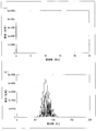
- A) And (b) is a figure which shows the waveform of the sound data extract
- A) And (b) is a figure which shows the frequency spectrum of the sound data obtained by applying the sound data shown to (a) and (b) of FIG. 35 to a fast Fourier transform (FFT) process.
- FFT fast Fourier transform
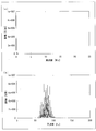
- A) and (b) are waveforms of sound data collected from an acoustic sensor or a sample of normal heart sounds stored in the sound source storage unit 232 when the wearing state is normal and good (improved).
- FIG. 39 It is a figure which shows the waveform of sound data which become.
- (A) And (b) is a figure which shows the frequency spectrum of the sound data obtained by applying the sound data shown to (a) and (b) of FIG. 37 to an FFT process.
- (A) And (b) is a figure which shows the waveform of the sound data extract
- (A) And (b) is a figure which shows the frequency spectrum of the sound data obtained by applying the sound data shown to (a) and (b) of FIG. 39 to FFT processing. It is a block diagram which shows the principal part structure of the analyzer in other embodiment of this invention.
- Embodiment 1 ⁇ Embodiment 1-1 >> An embodiment of the present invention will be described below with reference to the drawings.
- the biometric apparatus of the present invention acquires biological signal information from a sensor or the like that senses the state of a living body, and measures various states and symptoms of the living body using parameters obtained therefrom.
- a living body that is a subject of the biometric apparatus the state of a human (hereinafter referred to as a subject) is sensed using a biosensor, and the state and symptoms of the subject are measured.
- the biometric apparatus of the present invention is not limited to this, and an animal other than a human (for example, a dog) is treated as a subject (biological body), and the biological signal information of the animal is acquired to measure the state of the animal. It is also possible.
- the biometric apparatus of the present invention is realized by an information processing apparatus (such as a personal computer) provided separately from the various sensors that acquire the biosignal information. . Therefore, in the present embodiment, the biological signal information acquired by the sensor is supplied to the biological measurement device via appropriate wireless or wired communication means.
- the biometric device of the present invention is not limited to the above configuration, and may be realized by being incorporated in the sensor itself.
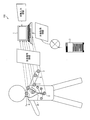
- FIG. 2 is a schematic diagram showing the configuration of the biometric system 100 in the embodiment of the present invention.
- the biometric system 100 of the present invention is configured to include at least one or more biosensors (2 to 6 and 8) and an analysis apparatus (biological measurement apparatus) 1.
- the biometric system 100 may include an information providing device 7 that provides various types of information related to the measurement of the subject.
- the biological sensor senses the state of the subject and supplies the detected biological signal information to the analysis device 1.
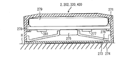
- the biosensor includes an acoustic sensor 2 (acoustic sensors 2 a and 2 b) that detects sound emitted by the subject, and a pulse oximeter that measures the subject's percutaneous arterial oxygen saturation (SpO 2 ). 3, a pulse wave sensor 4 that detects the pulse wave of the subject, a thermometer 5 that measures the body temperature of the subject, and an acceleration sensor 6 that detects the body movement (body motion) of the subject.
- an electrocardiograph 8 that detects the electrical activity of the subject's heart may be provided as a biosensor.
- Various sensors transmit biological signal information (sound, SpO 2 , pulse wave, body temperature, acceleration, electrocardiogram, etc.) detected by the own device to the analysis device 1.
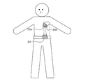
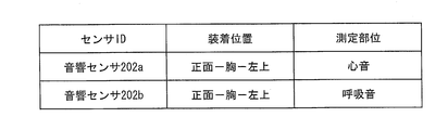
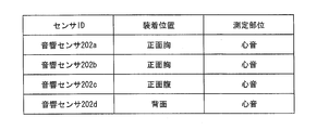
- the acoustic sensors 2a and 2b are close-contact microphones that are attached to the body of the subject and detect sound generated by the subject.
- An adhesive layer is provided on the surface of the acoustic sensor 2, and the acoustic sensor 2 is attached to the body surface of the subject by the adhesive layer.
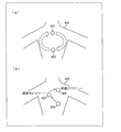
- the mounting position of the acoustic sensor 2 may be a location where the target sound can be effectively picked up.
- the acoustic sensor 2a for detecting the subject's breathing sound, coughing sound, etc. is mounted near the airway, and the subject's heart sound and heartbeat
- the acoustic sensor 2b for detecting the number and the like is attached to the left chest (viewed from the subject).
- the acoustic sensor 2a transmits sound data of the detected breathing sound to the analysis device 1 as biological signal information.
- the acoustic sensor 2b transmits sound data of the detected heart sound to the analysis device 1 as biological signal information.
- the pulse oximeter 3 includes LEDs that emit red light and infrared light, respectively, and the arterial blood oxygen saturation is calculated based on the amount of transmitted light generated as a result of the light emitted from these LEDs passing through the fingertip of the subject. measure. Further, the pulse rate may be measured.
- the pulse oximeter 3 transmits measurement data in which the measured SpO 2 is associated with the measurement time to the analysis device 1 as biological signal information.
- the electrocardiograph 8 detects the electrical activity of the heart.
- the electrocardiograph 8 does not measure the state of the subject at rest (electrocardiogram) for a short time, but continuously measures the state of the subject during daily life. Used for purposes. Therefore, it is preferable to adopt a Holter electrocardiograph as the electrocardiograph 8.
- the Holter electrocardiograph can continuously measure the electrocardiogram during the daily life of the subject over a long period of time (24 hours a day or more).
- the electrocardiograph 8 is composed of an electrode attached to the body of the subject and a measuring instrument main body. The measuring instrument main body controls each electrode, analyzes the electrical signal obtained from each electrode, and creates an electrocardiogram.
- the measuring instrument main body has a function of communicating with the analysis apparatus 1 and transmits the created electrocardiogram data to the analysis apparatus 1 as biological signal information.
- the electrocardiograph 8 has a shape that is small, lightweight, and excellent in portability so as not to hinder the daily life of the subject.
- the analysis apparatus 1 can analyze the electrocardiogram supplied from the electrocardiograph 8 and extract parameters representing the heart activity state such as the heart rate and the QRS width.
- the analysis apparatus 1 measures the state of the subject based on the biological signal information acquired from the biological sensor.
- the analysis device 1 extracts one or a plurality of various information related to the subject from the acquired biological signal information. And a measurement result can be obtained by using these as a parameter and applying to a biometric process.
- the analysis apparatus 1 of the present invention can select parameters to be used for the above-described biometric processing depending on the purpose of measurement of what state the subject wants to measure, that is, the measurement item. For this reason, the accurate determination suitable for the purpose of the measurement can be realized.
- the analysis device 1 is directly input to the external device and external acquisition information acquired from a device other than the biosensor (such as the information providing device 7). Parameters can be extracted from manually input information and used.
- a parameter obtained from the biological signal information of the biological sensor is referred to as a “biological parameter”, and a parameter obtained from the externally acquired information or the manual input information is referred to as an “external parameter”. Is used when it is necessary to distinguish between
- the biological parameter reflects the physiological state of the subject.
- the biological parameter for example, “volume” and “frequency” acquired from sound data (biological signal information) detected by the acoustic sensor 2 are assumed. Further, when the waveform is patterned, by analyzing the waveform pattern, the “presence / absence”, “long / short”, “number of times”, etc. of the waveform may be extracted as biological parameters.
- electrocardiogram biological signal information
- biological signal information biological signal information
- External parameters reflect the environmental conditions outside the body of the subject, whereas the biological parameters reflect the physiological state of the subject.
- Specific examples of the external parameter include, for example, the specification information of the biosensor (version information, what kind of information can be detected, etc.), and the installation position information of the biosensor (chest, abdomen, back, airway) Nearby), subject (subject) information about the subject (subject's age, gender, sleep time, last meal time, exercise amount, past disease history, etc.) and the measurement environment (temperature, Atmospheric pressure, humidity, etc.), but is not limited thereto.
- the analysis apparatus 1 can achieve a more accurate determination suitable for the purpose of measurement by deriving the measurement result by appropriately combining the external parameter with the external parameter. Below, the structure of this analyzer 1 is demonstrated in detail.
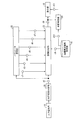
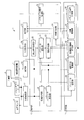
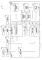
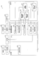
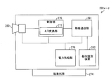
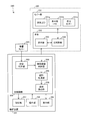
- FIG. 1 is a block diagram showing a main configuration of an analysis apparatus 1 according to an embodiment of the present invention.
- the analysis device 1 includes a control unit 10, a storage unit 11, a wireless communication unit 12, a communication unit 13, an input operation unit 14, and a display unit 15.
- the wireless communication unit 12 wirelessly communicates with various biological sensors in the biological measurement system 100.
- the wireless communication means it is assumed that short-range wireless communication means such as Bluetooth (registered trademark) communication or WiFi communication is adopted and direct short-range wireless communication is performed with various biological sensors.
- short-range wireless communication means such as Bluetooth (registered trademark) communication or WiFi communication
- WiFi communication wireless local area network
- a local area LAN may be constructed, and wireless communication with various biological sensors may be performed via the local area LAN.
- the analysis device 1 may not include the wireless communication unit 12 when performing wired communication with the biosensor, but it is preferable to realize communication between each biosensor and the analysis device 1 wirelessly. . This is because wireless communication makes it easy to attach the biosensor to the subject, reduces restrictions on the behavior of the subject in the measurement environment, and reduces the stress and burden on the subject.
- the communication unit 13 communicates with an external device (such as the information providing device 7) via a wide area communication network.
- the communication unit 13 transmits / receives information to / from the information providing device 7 via the Internet or the like.
- the analysis device 1 receives externally acquired information for extracting external parameters used for the biological measurement process from the information providing device 7 via the communication unit 13.
- external acquisition information acquired by the communication unit 13 weather, temperature, atmospheric pressure, humidity, specification information of each biosensor to be used, and the like are assumed.
- the analysis device 1 determines which biometric sensor should be used according to which measurement item, or compatibility when using a plurality of biosensors simultaneously. It is possible to grasp the good and bad and contraindications.
- the input operation unit 14 is used by a user (including a subject himself or an operator who performs measurement) to input an instruction signal to the analysis apparatus 1.
- the input operation unit 14 is a keyboard, a mouse, a touch panel, a touch sensor, a touch pen, or an appropriate input such as a voice input unit and a voice recognition unit configured by a plurality of buttons (cross key, determination key, character input key, etc.). Consists of devices.
- the user directly inputs information (manual input information) necessary for measuring the purpose (measurement item) of the measurement to be started from the input device 14 using the input operation unit 14. For example, parameters such as the subject's age, sex, average sleep time, sleep time on the measurement date, latest meal time, meal content, and amount of exercise are input to the analysis apparatus 1 via the input operation unit 14.
- the display unit 15 displays the measurement result of the biometric processing executed by the analysis device 1 or displays an operation screen for the user to operate the analysis device 1 as a GUI (Graphical User Interface) screen.
- GUI Graphic User Interface
- the user can display an input screen for inputting each of the parameters described above, or the user can display an operation screen for instructing the start of measurement by specifying a measurement item, Display a result display screen showing the measurement results.
- the display unit 15 is configured by a display device such as an LCD (Liquid Crystal Display).
- the control unit 10 performs overall control of each unit included in the analysis device 1 and includes, as functional blocks, an information acquisition unit 20, a parameter extraction unit 21, a parameter selection unit 22, an index calculation unit 23, a state determination unit 24, and A measurement item determination unit 25 is provided.
- Each of these functional blocks includes a CPU (central processing unit), a program stored in a storage device (storage unit 11) realized by a ROM (read only memory), etc., a RAM (random access memory) (not shown), and the like. This can be realized by reading out and executing.
- the storage unit 11 includes (1) a control program executed by the control unit 10, (2) an OS program, (3) an application program for the control unit 10 to execute various functions of the analysis device 1, and (4 ) Stores various data to be read when the application program is executed.
- the storage unit 11 stores various programs and data that are read when the biological measurement process executed by the analysis apparatus 1 is executed.
- the storage unit 11 includes a parameter storage unit 30, a measurement method storage unit 31, an index calculation rule storage unit 32, and an index storage unit 33.
- the analysis device 1 includes a temporary storage unit (not shown).
- the temporary storage unit is a so-called working memory that temporarily stores data used for calculation, calculation results, and the like in the course of various processes executed by the analysis apparatus 1, and includes a RAM or the like.
- the information acquisition unit 20 of the control unit 10 acquires various information necessary for the biological measurement process. Specifically, the information acquisition unit 20 acquires biological signal information from the biological sensor via the wireless communication unit 12. The information acquisition unit 20 acquires external acquisition information from the information providing device 7 via the communication unit 13. Further, the information acquisition unit 20 acquires manual input information input to the own device via the input operation unit 14. For example, the information acquisition unit 20 acquires sound data of the breathing sound of the subject from the acoustic sensor 2a as biological signal information.
- the information acquisition unit 20 communicates with each biosensor when the measurement item when the analysis apparatus 1 executes the biometric measurement process is determined, and a biosensor necessary for measurement of the measurement item is obtained. It may be confirmed whether or not communication is possible (active state).
- the parameter extraction unit 21 extracts parameters used for the biometric measurement process from various information acquired by the information acquisition unit 20.
- the parameter extraction unit 21 extracts biological parameters from the biological signal information acquired from the biological sensor, and extracts external parameters from externally acquired information acquired from the outside or manual input information input to the device itself.
- the parameter extraction unit 21 is configured to extract parameters designated by default from predetermined biological signal information. For example, “sound volume” and “frequency” are extracted from the sound data.
- the measurement method storage unit 31 is referred to, and the separate parameter is acquired according to the extraction method stored in the measurement method storage unit 31.
- the separate parameter is “a maximum value among the frequencies detected in ⁇ minutes” or the like, and is a parameter extracted through a more complicated analysis procedure.
- the parameter extraction unit 21 stores the extracted parameters in the parameter storage unit 30 in association with the acquired biological signal information or biological sensor.
- the measurement item determination unit 25 determines the purpose of measurement of the biological measurement process to be executed by the analysis apparatus 1, that is, the measurement item. There are several methods for determining the measurement item. As the simplest configuration, a configuration is possible in which measurement items that can be measured by the analysis apparatus 1 are presented to the user via the display unit 15 and are selected by the user via the input operation unit 14. The measurement item determination unit 25 transmits information on measurement items specified by the user to each unit of the analysis apparatus 1.
- the parameter selection unit 22 selects a parameter necessary for executing the biometric measurement process related to the measurement item according to the measurement item designated by the user.
- the parameter selection unit 22 refers to the parameter designation information stored in the measurement method storage unit 31 and selects a parameter that matches the designated measurement item.
- the operation of the parameter selection unit 22 will be described later in detail based on the data structure of the measurement method storage unit 31.
- the index calculation unit 23 uses the parameter selected by the parameter selection unit 22 to calculate an index corresponding to the designated measurement item.
- the index calculation unit 23 reads out the index calculation rule stored in the index calculation rule storage unit 32 corresponding to the specified measurement item, and determines the index of the specified measurement item according to the index calculation rule. calculate.
- the index calculation unit 23 follows the “apnea degree calculation rule” stored in the index calculation rule storage unit 32 and the index “apnea degree”. Is calculated.
- the data structure of the index calculation rule will be described later.
- the index calculation unit 23 stores the calculated index in the index storage unit 33.
- the index may be accumulated in association with the measurement date and time and the subject information (subject information).
- the state determination unit 24 determines the state of the subject based on the index calculated by the index calculation unit 23. Determination criterion information is stored in the index calculation rule storage unit 32, and the state determination unit 24 determines the state of the subject based on the calculated index according to the determination criterion information. For example, the state determination unit 24 determines the state of the subject related to the measurement item by a three-step evaluation of “normal”, “attention required”, and “abnormal”.
- the measurement results output by the index calculation unit 23 and the state determination unit 24, that is, the indexes and the state determination result of the subject are output to the display unit 15. Thereby, it becomes possible to present a measurement result to a user in an easy-to-understand manner.
- the parameter storage unit 30 stores the parameters extracted by the parameter extraction unit 21.
- the extracted parameters are managed for each parameter type so that the analysis apparatus 1 can identify them.
- the parameter types are “volume”, “frequency”, and the like, for example. Furthermore, when a plurality of subjects are measured using a plurality of biosensors, it is desirable that each parameter is managed for each subject ID and each biosensor ID.
- the measurement method storage unit 31 stores parameter designation information for designating the type of parameter used for the biological measurement process for each measurement item.
- the measurement method storage unit 31 stores the mounting position designation information for each measurement item and for each type of biosensor when the mounting position of the biosensor differs depending on the measurement item even for the same type of biosensor. You may remember it. Thereby, when each measurement item is designated, each unit of the analysis apparatus 1 has an error such as that the biometric sensor is not mounted at an appropriate position or cannot communicate with a biometric center mounted at an appropriate position. Can be detected and dealt with.
- the measurement method storage unit 31 may store an index that is finally calculated for each measurement item in association with each other.
- the index calculation unit 23 can recognize what index should be calculated when a measurement item is designated. For example, when the measurement item “apnea measurement” is designated, it is recognized that the corresponding index “apnea” is calculated.
- the index calculation rule storage unit 32 stores an index calculation rule for calculating an index for each measurement item.
- the index calculation rule indicates an algorithm for all processes until an index is calculated using a selected parameter. For example, when the measurement item “apnea measurement” is designated, the index calculation unit 23 reads the “apnea calculation rule” from the index calculation rule storage unit 32, and the index is calculated according to the algorithm indicated there. The “apnea level” can be calculated. Furthermore, in the index calculation rule storage unit 32, determination criterion information for determining the state of the subject based on the calculated index is stored in association with each measurement item.
- the state determination unit 24 refers to the determination standard information of the apnea degree, and according to the determination standard, the state of the subject regarding the measurement item “apnea measurement” Determine.
- the index storage unit 33 stores the index calculated by the index calculation unit 23.
- the calculation of the index is preferably performed periodically, and the calculated index is preferably stored in association with the measurement date and subject information. This makes it possible to observe changes over time for the same index of the same subject, and more accurately determine the state of the subject (particularly normal or abnormal).
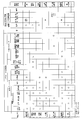
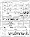
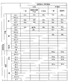
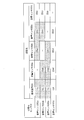
- FIG. 3A and 3B are diagrams showing the data structure of information stored in the measurement method storage unit 31.
- FIG. 3A illustrates a correspondence relationship between measurement items for parameter designation information regarding general-purpose parameters, mounting position designation information, and corresponding indexes, using a specific example.
- FIG. 3B shows the correspondence between the parameter designation information related to the special parameter and the measurement item using a specific example.
- an essential parameter (hereinafter, an essential parameter) is associated with an auxiliary parameter (auxiliary parameter) for the purpose of improving accuracy.
- an essential parameter hereinafter, an essential parameter
- auxiliary parameter auxiliary parameter
- each part (especially parameter selection part 22) of the control part 10 which performs a biological measurement process will start based on the determined measurement item, if a measurement item is determined by the measurement item determination part 25. Parameters necessary for the biological measurement process can be grasped.
- each unit when performing the biometric measurement process of the measurement item “1: apnea measurement”, each unit must have parameters for waveform presence / absence, volume, waveform length short / number of waveforms, and optionally SpO 2 and heart rate. It can be recognized that the following parameters are used.
- the biosensor particularly the acoustic sensor 2
- the optimal mounting is required in order to perform accurate measurement suitable for the measurement item. It is desirable that the position is fixed. Therefore, as shown in FIG. 3A, mounting position designation information is stored in association with each measurement item.
- essential parameters are obtained for the respiratory sound that can be collected from the vicinity of the airway by making it necessary to attach an acoustic sensor to the airway. That is, each unit of the control unit 10 can recognize it.
- the information acquisition unit 20 provides information on whether necessary information should be acquired from the biological sensor. It can be grasped from the device 7 or user input.
- biosensors to be used are determined in advance (FIG. 2), and the correspondence between these biosensors and parameters that can be extracted is grasped in advance as follows. .
- the parameters of waveform presence / absence, volume, frequency, waveform length, and number of waveforms can be extracted from the biological signal information of the acoustic sensor 2a (the mounting position is arbitrary and specified by the mounting position specifying information).
- the heart rate parameter may be extracted together.
- the heart rate parameter can be extracted from the biological signal information of the acoustic sensor 2b (the wearing position is fixed at the left chest).
- the SpO 2 parameter can be extracted from the biological signal information of the pulse oximeter 3 (the mounting position is fixed with a fingertip). Further, a pulse rate parameter may be extracted.
- Parameters of pulse wave propagation speed and pulse rate can be extracted from the biological signal information of the pulse wave sensor 4 (the mounting position is arbitrary and specified by the mounting position specifying information).
- the parameters of body temperature and body temperature change can be extracted from the biological signal information of the thermometer 5 (the wearing position is arbitrary and is designated by the wearing position designation information).
- the body motion parameters can be extracted from the biological signal information of the acceleration sensor 6 (the mounting position is arbitrary and specified by the mounting position specifying information).
- the optimal mounting position may be determined in advance by the mounting position designation information. That is, the mounting position designation information is not limited to the example illustrated in FIG. 3A.
- the information acquisition unit 20 of the analysis apparatus 1 grasps parameters necessary for the measurement and recognizes from which biological sensor the biological information signal should be acquired. be able to.
- the correct mounting position of the biosensor can be recognized and presented to the user.
- the configuration of the analysis apparatus 1 of the present invention is not limited to the above.
- the correspondence between the biological center and the parameter such as from which biometric sensor the parameter is acquired, which parameter is used for which measurement item without defining the above correspondence
- Only the correspondence between the measurement item and the parameter may be determined in the measurement method storage unit 31. Thereby, the structure of the analyzer 1 can be simplified and the processing load of the analyzer 1 can be reduced.
- an index type that can be calculated with respect to the measurement item may be associated and stored.
- the index calculation unit 23 can recognize which index should be calculated when the measurement item is determined.
- special parameters that define the extraction method in detail may be stored in association with each measurement item.
- the parameter “Waveform presence / absence” is used for the biological measurement process.
- a special parameter “presence / absence of waveform at a specific frequency of 100 to 200 Hz” is used as the measurement item “3: asthma measurement”. Correlate.
- the parameter selection unit 22 can determine that a special parameter “whether or not a waveform with a specific frequency of 100 to 200 Hz” is necessary when measuring the measurement item “3: asthma measurement”. Is not stored in the measurement method storage unit 31, the parameter extraction unit 21 can be requested to extract “whether or not the waveform has a specific frequency of 100 to 200 Hz”.
- the parameter extraction unit 21 may be configured to extract all parameters assumed in FIG. 3A and FIG. Or it is good also as a structure which extracts both a general-purpose parameter and a special parameter according to the request
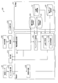
- FIG. 4 is a diagram for explaining a data flow between main members in the analysis apparatus 1 from when the analysis apparatus 1 receives an instruction to start the biometric measurement process until the measurement result of the process is output.
- the measurement item determination unit 25 receives an instruction to start the biological measurement process via the input operation unit 14 and also receives information on the measurement item selected by the user, and determines the measurement item as “1: Apnea measurement”. To do.
- the measurement item determination unit 25 transmits the determined measurement item d1 to the parameter selection unit 22, the index calculation unit 23, and the state determination unit 24.
- the parameter selection unit 22 refers to the measurement method storage unit 31 (FIGS. 3A and 3B), identifies the necessary parameters based on the transmitted measurement item d1, and identifies the identified parameters, that is, the waveform (respiration) d2, (breathing) volume d3, waveform (breathing) length d4, waveform (breathing) number d5, SpO 2 d6, and heart rate d7 are acquired from the parameter storage unit 30 and supplied to the index calculation unit 23.
- the waveform presence / absence d2 indicates “the number of times that respiration stops for 10 seconds or more” as shown in FIG. 3B.
- SpO 2 d6 and heart rate d7 are arbitrary auxiliary parameters, and therefore may not be supplied to the index calculation unit 23 unless stored in the parameter storage unit 30.
- the index calculation unit 23 reads the index calculation rule from the index calculation rule storage unit 32 based on the transmitted measurement item d1.
- the apnea degree calculation rule d8 is read.
- the apnea degree calculation rule d8 indicates an algorithm for calculating the apnea degree using the parameters d2 to d7 described above.
- the index calculation unit 23 calculates the apnea degree d9 using the parameters d2 to d7 according to the apnea degree calculation rule d8.
- the state determination unit 24 reads the calculated criterion determination criterion information from the index calculation rule storage unit 32.
- the criterion information d10 of the calculated apnea degree d9 is read out.
- the criterion information d10 is information indicating a criterion for determining a state related to apnea of the subject based on the apnea degree d9.
- the state determination unit 24 determines whether the state or symptom related to the apnea of the subject is normal, needs attention, or is abnormal based on the apnea degree d9 according to the determination reference information d10, and the state determination result d11 is obtained. Output.
- the measurement result including the apnea degree d9 and the state determination result d11 is output to the display unit 15 and displayed. Thereby, the user can confirm the measurement result concerning the designated measurement item on the display unit 15.
- the analysis apparatus 1 may include a light emitting unit and notify the state determination result d11 by emitting light that is color-coded according to the state determination result, such as green, yellow, and red. Or it is good also as a structure which uses a light emission part selectively according to a state determination result, such as lighting, light extinction, and blinking. Alternatively, the state determination result d11 may be notified by providing a sound output unit and using sound or sound effects depending on the state determination result.
- the data structure of the index calculation rule storage unit 32 that stores the apnea calculation rule d8 and the determination reference information d10 will be described in more detail with a specific example.
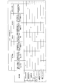
- FIGS. 5 to 11 are diagrams showing the data structure of the index calculation rule and the determination criterion information stored in the index calculation rule storage unit 32.
- FIG. Each of FIGS. 5 to 11 shows specific examples of index calculation rules and determination criterion information corresponding to the seven measurement items shown in FIGS. 3A and 3B.
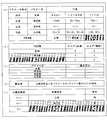
- FIGS. 5A to 5D are diagrams showing specific examples of apnea calculation rules
- FIG. 5E is a diagram showing a specific example of apnea determination criterion information.
- Sleep apnea syndrome is a symptom of falling into apnea or hypopnea frequently during sleep.
- the airflow in the mouth and nose is stopped for 10 seconds or more, and as a guideline for judging a hypopnea state, the ventilation volume is reduced by 50% or more for 10 seconds or more. Conceivable.
- the determination of apnea is as follows: presence or absence of breathing (number of times breathing stops for 10 seconds or more), volume of breathing sound, length of breathing (time length of expiration and inspiration), per unit time
- the respiratory rate and SpO 2 parameters were used.
- the “apnea level” in the present embodiment indicates that the higher the value, the higher the possibility of sleep apnea syndrome.
- the example of the parameter used for determination of apnea degree is an example, and is not limited to the example mentioned above.
- a pulse rate parameter may be used.
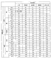
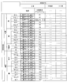
- the apnea degree calculation rule evaluates each parameter obtained from the parameter selection unit 22 as a normal value, a caution value, or an abnormal value in three stages. Corresponding relationships are included. In the example shown in FIG. 5A, this correspondence relationship is expressed in a table format, but this is an example and there is no intention to limit the present invention.
- IF values For each parameter, three types of threshold values (IF values) are stored in association with each other, and each of the three types of IF values is associated with a three-stage evaluation result (THEN value) of normal, caution, and abnormality. ing. That is, the THEN value of the parameter is determined depending on which of the three IF values satisfies the parameter value.
- THEN value three-stage evaluation result
- the threshold value stored as the IF value in the table is not limited to the example shown in the figure, and an appropriate value may be determined based on medical grounds and experience.
- the apnea calculation rule includes score information for assigning a score corresponding to the evaluation to the parameters evaluated in three stages.
- the score information is expressed in a table format, but this is an example and there is no intention to limit the present invention.
- the index calculation unit 23 sets 0 for a parameter evaluated as “normal”, 1 for a parameter evaluated as “attention required”, and “abnormal”.
- a score of 2 is assigned to the evaluated parameter.
- scores of 0, 0, and 1 are assigned to the parameters of “normal”, “attention required”, and “abnormal”, respectively.
- the waveform (respiration) presence / absence d2 parameter is evaluated as “normal”, the waveform (respiration) presence / absence d2 parameter is essential, and therefore a score “0” is assigned.
- the apnea calculation rule may include weighting information to be given to the score obtained for each parameter.
- the weighting information is expressed in a table format, but this is an example and there is no intention to limit the present invention.
- the weight is stored in association with each parameter. A large weighting value indicates that the parameter is information that is more important and important in calculating the index.
- the waveform (breathing) presence / absence d2 indicating “the number of times breathing stops for 10 seconds or more” is the most important information to be considered in calculating the apnea degree. Therefore, the weight is set to “4”.
- a parameter that is not very important, the number of waveforms (breathing), SpO 2 , and heart rate may not be weighted, that is, the weight may be set to “1”.
- the apnea degree calculation rule includes a calculation formula for calculating the index “apnea degree” based on the score of each parameter.
- the calculation formula of (d) of FIG. 5 is an example, and is not intended to limit the present invention.
- the index calculation unit 23 calculates the apnea degree by summing the final scores of the parameters d2 to d7.
- the index calculation rule storage unit 32 stores determination criterion information for determining the state of the subject regarding the index “apnea level”.
- the determination criterion information is expressed in a table format, but this is an example and is not intended to limit the present invention.
- the state determination result to be determined is associated with the calculated apnea value.
- the state determination unit 24 determines the state related to the apnea of the subject according to the determination criterion information illustrated in FIG. For example, when the apnea degree is calculated as “3”, the state determination unit 24 determines that the state related to the apnea of the subject is “normal”.
- information defining a method for displaying the state determination result may be associated with the determination criterion information table.
- the display “green” is associated with the state determination result “normal”. This means that the state determination result is displayed in green letters or notified with a green lamp.
- the state determination result is color-coded and output, so that the user can more intuitively understand the state determination result.
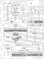
- FIGS. 6A to 6D are diagrams showing a specific example of the sleep depth calculation rule
- FIG. 6E is a diagram showing a specific example of the sleep depth determination criterion information.
- the “sleep depth” in the present embodiment indicates that the higher the value, the deeper the sleep.
- the sleep depth calculation procedure and the state determination procedure based on the various types of information in FIGS. 6A to 6E are parameters used in comparison with the procedure based on FIGS. 6A to 6E. This is the same except that the threshold is different. Therefore, description is not repeated here. However, in the determination of the sleep depth, not the presence / absence of abnormality, but the determination of the sleep depth and depth is performed.
- FIGS. 7A to 7D are diagrams showing specific examples of asthma severity calculation rules
- FIG. 7E is a diagram showing a specific example of determination criteria information for asthma severity.
- “Asthma severity” in the present embodiment indicates that the higher the value, the more severe the symptoms of asthma.
- the procedure for calculating the severity of asthma and the procedure for determining the state based on various types of information in FIGS. 7A to 7E are used in comparison with the procedure based on FIGS. 5A to 5E. The same except that the parameters and thresholds are different. Therefore, description is not repeated here.
- FIGS. 8A to 8D are diagrams illustrating specific examples of rules for calculating the heart activity level
- FIG. 8E is a diagram illustrating a specific example of criteria information for determining the heart activity level.
- the “heart activity” in the present embodiment indicates that the higher the value, the more unstable and abnormal the heart activity.
- the cardiac activity calculation procedure and the state determination procedure based on the various types of information in (a) to (e) of FIG. 8 are used in comparison with the procedure based on (a) to (e) of FIG. The same except that the parameters and thresholds are different. Therefore, description is not repeated here.
- FIGS. 9A to 9E are diagrams showing specific examples of rules for calculating digestive organ activity
- (e) is a diagram showing specific examples of criteria information for digestive activity.
- “Digestive activity” in the present embodiment indicates that the higher the value, the more unstable and abnormal the digestive activity.
- the digestive activity level calculation procedure and state determination procedure based on the various types of information in FIGS. 9A to 9E are used in comparison with the procedure based on FIGS. 5A to 5E. This is the same except that the parameters and thresholds to be used are different. Therefore, description is not repeated here.
- FIGS. 10A to 10D are diagrams showing specific examples of the cardiovascular activity calculation rule
- FIG. 10E is a diagram showing a specific example of the criteria information for determining cardiovascular activity.
- “Cardiovascular activity” in the present embodiment indicates that the higher the value, the more unstable and abnormal the activity of the cardiovascular activity.
- the procedure for calculating the degree of circulatory activity and the procedure for determining the state based on the various types of information in FIGS. 10 (a) to (e) are used in comparison with the procedure based on (a) to (e) in FIG. This is the same except that the parameters and thresholds to be used are different. Therefore, the overlapping description will not be repeated here.
- the age of the subject may be used as an auxiliary external parameter in calculating the cardiovascular activity. Since the health condition of the circulatory organ (particularly blood vessels) greatly depends on the age, the state determination suitable for the age of the subject can be performed by considering the age of the subject.
- the IF value (threshold value) of the essential parameter “pulse wave (propagation velocity)” shown in FIG. More specifically, for example, a normal IF value “less than 1200 cm / s”, a cautionary IF value “more than 1200 cm / s and less than 1400 cm / s”, and an abnormal IF value shown in FIG.
- the circulatory activity can be calculated with higher accuracy by changing the weighting value of the parameter of the pulse wave (propagation speed) according to the age of the subject. it can.
- another index “degree of arteriosclerosis” may be calculated using the same parameters as those for calculating the degree of cardiovascular activity.
- the index calculation rule storage unit 32 may separately store an arteriosclerosis calculation formula as an arteriosclerosis calculation rule.
- FIGS. 11A to 11D are diagrams showing specific examples of cough severity calculation rules
- FIG. 11E is a diagram showing specific examples of criteria information for determining cough severity.
- the “cough severity” in the present embodiment indicates that the higher the value, the more severe the cough symptoms and the higher the probability of being abnormal.
- the cough severity calculation procedure and state determination procedure based on the various types of information shown in FIGS. 11A to 11E are used in comparison with the procedure based on FIGS. 5A to 5E. The same except that the parameters and thresholds are different. Therefore, the overlapping description will not be repeated here.
- the disease history of the subject may be used as an auxiliary external parameter in calculating the cough severity.
- Patients with respiratory disease often develop a characteristic cough (specific frequency cough), and the effects of coughing from the original respiratory disease must be subtracted here. Therefore, for example, as shown in FIG. 11 (c), the cough severity can be calculated more accurately by changing the weighting value of the frequency parameter according to whether or not the subject is a respiratory disease patient. Can do.
- the index calculation unit 23 processes the parameter selected according to the measurement item according to the index calculation rule according to the measurement item, and calculates the index. Therefore, the index calculation unit 23 is more accurate and suitable for the measurement item. A biometric process can be performed.
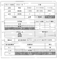
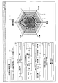
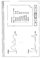
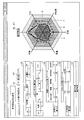
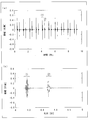
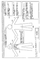
- [Measurement result display example] 12 to 18 are diagrams illustrating examples of display screens when the measurement result obtained by the analysis apparatus 1 executing the biological measurement process is displayed on the display unit 15.
- FIG. 12 shows an example in which the analysis apparatus 1 displays the measurement result obtained when the biometric measurement process is executed for the measurement item “1: apnea measurement”.
- the index calculated by the index calculation unit 23 (here, “apnea degree d9”) and the state determination result d11 determined by the state determination unit 24 are displayed as measurement results.
- the apnea degree d9 and the state determination result d11 are preferably displayed in a format that is easy for the user to understand, and may be displayed in text or may be displayed in various forms of graphs.
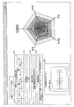
- the measurement result can be displayed in a text and radar chart format.
- the calculated index is set to the center upper axis
- the parameter used for calculating the index is set to the other direction axis
- the center is 0, and the maximum value that can take the outside of the axis is set.
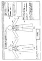
- the calculated index indicates that the smaller the value, that is, the closer to the center of the chart, the “normal”, so the area A closest to the center is “normal” and the middle area B is “noticeable”. ”And the outer region C is“ abnormal ”.
- the intermediate value is “normal” and the value becomes “careful” or “abnormal” if the value is too small or too large.
- the region A closest to the center and the outer region C represent “abnormal”
- the middle region B represents “normal”.
- the vicinity of the boundary between the area A and the area B and the vicinity of the boundary between the area A and the area C mean “attention required”.
- the boundary position of each region changes depending on the index criterion information and the IF value of each parameter, so the length from the center to the boundary position may vary from axis to axis. Further, the axes for plotting the index and each parameter do not have to be all on the same plane. If the display area is wide, a plurality of radar charts may be created and displayed.
- the national average value, ideal value, previous measurement value of the same subject, etc. may be plotted and displayed as a broken line D so that it can be compared with the current measurement result (solid line).
- the information acquisition unit 20, the parameter selection unit 22, and the index calculation unit 23 may output various types of information obtained when referring to the measurement method storage unit 31 to the display unit 15.
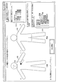
- the information acquisition unit 20 includes information 120 indicating the type of the biosensor used (communication) used in the measurement of the measurement item “apnea measurement”, and mounting position designation information on the biosensor.
- information 121 indicating the mounting position of the sensor is displayed.
- the parameter selection unit 22 displays parameter information 122 selected as an essential parameter and parameter information 123 selected as an auxiliary parameter for the measurement item “apnea measurement”.
- the index calculation unit 23 displays index information 124 corresponding to the measurement item “apnea measurement”.
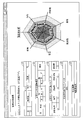
- FIG. 13 shows an example in which the analysis apparatus 1 displays the measurement result obtained when the biometric processing is executed for the measurement item “2: sleep state measurement”.
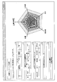
- FIG. 14 shows an example in which the analysis apparatus 1 displays the measurement result obtained when the biometric measurement process is executed for the measurement item “3: Asthma measurement”.
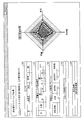
- FIG. 15 shows an example in which the analysis apparatus 1 displays the measurement result obtained when the biometric processing is executed for the measurement item “4: heart monitoring”.
- FIG. 16 shows an example in which the analysis apparatus 1 displays the measurement result obtained when the biometric measurement process is executed for the measurement item “5: digestive organ monitoring”.
- FIG. 17 shows an example in which the analysis apparatus 1 displays the measurement result obtained when the biometric measurement process is executed for the measurement item “6: cardiovascular monitoring”.
- the index calculation unit 23 of the analysis apparatus 1 can calculate the index “degree of arteriosclerosis” using the same parameter as the measurement item “6: cardiovascular monitoring”.
- the display may be switched to a radar chart related to the index “degree of arteriosclerosis” in accordance with a user operation.
- FIG. 18 shows an example in which the analysis apparatus 1 displays the measurement result obtained when the biometric processing is executed for the measurement item “7: cough monitoring”.
- the user can confirm the information displayed on the display unit 15 and easily grasp the measurement result related to the selected measurement item.
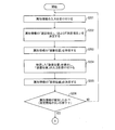
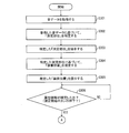
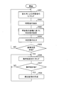
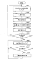
- FIG. 19 is a flowchart showing the flow of the biometric measurement process executed by the analysis apparatus 1.
- the measurement item determination unit 25 When an instruction to start measurement of the subject is input to the analysis apparatus 1 via the input operation unit 14 (YES in S1), the measurement item determination unit 25 then sets the “measurement item”. An input is accepted (S2). For example, when the user selects the measurement item “apnea measurement”, the measurement item determination unit 25 determines “1: apnea measurement” as the measurement item of the biological measurement process to be started.
- the information acquisition unit 20 refers to the measurement method storage unit 31 and confirms whether or not all the biosensors necessary for measuring the determined measurement item are active (S3).
- the information acquisition unit 20 determines whether at least the acoustic sensor 2a is active among the acoustic sensor 2a mounted near the airway, the acoustic sensor 2b mounted on the left chest, and the pulse oximeter 3. Check.
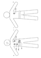
- the information acquisition unit 20 When the essential biosensor is inactive (NO in S3), the information acquisition unit 20 notifies the user that the biosensor is inactive and cannot be measured via the display unit 15. It is preferable to do this (S4). At this time, it is more preferable to notify the user of the type of necessary biosensor and the correct mounting position (near the airway and left chest) in a form that is easy to understand for the user (for example, in the drawing).
- the information acquisition unit 20 acquires biosignal information from each of these biosensors (S5).
- the information acquisition unit 20 acquires at least sound data near the airway from the acoustic sensor 2a, optionally, sound data of heart sounds from the acoustic sensor 2b, and measurement data of SpO 2 from the pulse oximeter 3. To do.
- the information acquisition unit 20 receives external acquisition information (such as the measurement day's climate, temperature, humidity, and atmospheric pressure) from the information providing device 7 and manual input information (subject ID or subject name, subject's subject) via the input operation unit 14. Age, sex, etc.) may be acquired as necessary (S6).
- external acquisition information such as the measurement day's climate, temperature, humidity, and atmospheric pressure
- manual input information subject ID or subject name, subject's subject
- Age, sex, etc. may be acquired as necessary (S6).
- the parameter extraction unit 21 extracts biological parameters from the acquired biological signal information (S7).
- the parameter extraction unit 21 may extract only the parameters used in the selected measurement item “1: apnea measurement” with reference to the measurement method storage unit 31 or the parameters listed in FIG. 3A. Of these, all parameters that can be extracted may be extracted. Further, when the external acquisition information and the manual input information are acquired, the parameter extraction unit 21 extracts external parameters from them (S8).
- the parameter extraction unit 21 stores the extracted parameters in the parameter storage unit 30.
- the parameter selection unit 22 refers to the measurement method storage unit 31 (FIGS. 3A and 3B) and selects a parameter to be used for the determined measurement item from the parameters stored in the parameter storage unit 30 ( S9).
- the parameter selection unit 22 associates the measurement item “1: apnea measurement” with or without the (airway) waveform, volume, waveform length, waveform number, SpO 2 and heart rate parameters. Select.
- parameter selection unit 22 When parameter selection unit 22 has obtained all necessary parameters from parameter storage unit 30 (YES in S10), it supplies it to index calculation unit 23 (S11).
- the index calculation unit 23 reads an index calculation rule corresponding to the selected measurement item from the index calculation rule storage unit 32 (S12), and calculates an index of the measurement item according to the index calculation rule (S13). .
- the “apnea level calculation rule” (for example, (a) to (d) of FIG. 5) corresponding to the measurement item “1: apnea level measurement” is read and supplied from the parameter selection unit 22.
- the apnea is calculated using the parameters.
- the calculated apnea degree is stored in the index storage unit 33 together with the measurement date, the subject ID, and the like.
- the state determination unit 24 determines the state of the subject based on the calculated index (S14).
- the state determination unit 24 performs determination according to the determination criterion information corresponding to the selected measurement item.
- the state determination unit 24 determines whether the apnea of the subject is normal. Determine if it needs attention or is abnormal.
- the index calculation unit 23 outputs the calculated index
- the state determination unit 24 outputs the result of the determination made to the display unit 15.
- the display unit 15 displays the measurement result and presents it to the user (S15).
- the measurement result is an execution result of a series of steps of the biometric processing shown in FIG. 19 executed by the analysis apparatus 1, and includes at least the calculated index and the determination result of the state. Furthermore, attached information such as information on the parameters used and what kind of index is calculated may be included in the measurement result. Display examples of the measurement results are as shown in FIGS.
- the parameter extraction unit 22 is based on the parameter designation information stored in the measurement method storage unit 31. 21 is preferably instructed to extract necessary parameters (S16). For example, according to the parameter designation information shown in FIG. 3B, the “apnea measurement” requires a parameter of “the number of times breathing stops for 10 seconds or more” with respect to the presence or absence of the waveform.
- the parameter selection unit 22 makes a request to the parameter extraction unit 21.
- the parameter extraction unit 21 extracts parameters according to the instructions, stores them in the parameter storage unit 30, and returns a response to the parameter selection unit 22.
- the analyzer 1 can be configured to extract, by default, highly versatile parameters for various measurement items, while extracting special parameters for specific measurement items as necessary. Thereby, it is possible to reduce the processing load of the biological measurement process and improve the processing efficiency.
- the analysis device 1 is configured to calculate one index by one biometric process and determine the state of the subject based on the calculated one index.
- the configuration of the analysis apparatus 1 of the present invention is not limited to this.
- the analysis apparatus 1 may measure a plurality of times for one measurement item by changing the date and time (that is, repeatedly obtain a biological parameter), and calculate the index a plurality of times. And the analysis apparatus 1 may determine a test subject's state by calculating
- the analysis apparatus 1 of the present invention stores, in the measurement method storage unit 31, in association with each measurement item, repeated measurement instruction information that specifies the timing for repeatedly calculating the corresponding index. ing.
- each unit of the control unit 10 illustrated in FIG. 1 refers to the measurement method storage unit 31 and the measurement item determined by the measurement item determination unit 25 Is read, and the timing of measurement is recognized.
- a time interval for periodically measuring such as “calculating an index for one month at a pace of once a day”, or a period for periodically measuring is specified.
- zone which performs a measurement may be defined in detail.
- each part of the control part 10 performs the biometric process mentioned above regularly according to repeated measurement instruction information.
- the index calculation unit 23 stores the index calculated at a pace of once every 24 hours in the index storage unit 33 in association with the subject ID and the measurement date for 31 days.
- the state determination unit 24 determines the state of the subject related to the instructed measurement item based on the accumulated index. In the example described above, indices for one month are accumulated, and the state determination unit 24 determines the state of the subject using these values.
- the index processing method and the criterion information at this time may be stored in the index calculation rule storage unit 32 for each measurement item.
- the processing performed by the state determination unit 24 includes, for example, plotting the index value on a two-dimensional graph with the index value on the vertical axis and the time on the horizontal axis to analyze the transition of the index, It is conceivable to calculate statistical values such as average value, maximum value, minimum value, and variance. For example, the state determination unit 24 compares the analysis result thus obtained with a standard value to determine the state of the subject related to the measurement item (for example, determination of normality, caution, or abnormality). Do.
- the state determination unit 24 compares the index accumulated in the past according to the repeated measurement instruction information with the index obtained by the biometric process performed once thereafter, and the biometric process is performed. You may determine the newest state of a test subject at the time of being implemented. Thus, by comparing with past values, it is possible to accurately determine the current state of the subject.
- an analysis method is stored for each measurement item, such as which index in the past is used as a comparison and how it is compared with the latest index. Just do it.
- FIG. 20 is a diagram illustrating an example in which a long-term tendency of a subject's condition is displayed as a measurement result.
- the two-dimensional graph created by the state determination unit 24 may be displayed on the display unit 15 for each measurement item. Thereby, the user can grasp
- the two-dimensional graph shown in FIG. 20 is an example, and the present invention is not limited to this.
- the range of the horizontal axis (time) to be displayed may be changed as necessary. For example, by changing the measurement period from “1 month” to “1 year”, it is possible to display the overall state determination result of the subject for one year based on the index of the subject accumulated for one year.
- the measurement period option button is displayed and selected by the user, the user can switch the measurement period with a simple operation.
- the measurement item determination unit 25 of the analysis apparatus 1 is configured to determine the measurement item designated by the user via the input operation unit 14 as the measurement item that is the purpose of the biometric processing to be performed from now. It was.
- the configuration of the analysis apparatus 1 of the present invention is not limited to this.
- the analysis apparatus 1 is configured so that the measurement item determination unit 25 specifies the measurement item or allows the user to select and narrow down to some candidates depending on which active biosensor is. be able to.
- the measurement item determination unit 25 confirms active biosensors via the information acquisition unit 20, and specifies measurement items that can be measured using biosignal information from these biosensors.
- the measurement item determination unit 25 determines the measurement item as a measurement item of a biometric process to be executed from now.
- the measurement item determination unit 25 displays only those measurement items as options on the display unit 15 and allows the user to select them.
- Embodiment 1-2 Another embodiment of the present invention will be described below with reference to FIGS.
- members having the same functions as those in the drawings described in the above-described embodiments are denoted by the same reference numerals, and description of contents overlapping those in the above-described embodiments is omitted.
- the biometric apparatus (analysis apparatus 1) of the present invention is an index corresponding to a target measurement item based on the parameter information 122 and the parameter information 123 as shown in FIGS. It was only informing the user whether or not the parameter for calculating the parameter was adopted.
- the magnitude of the influence of each parameter on the calculation of the index varies within the analysis apparatus 1 for each parameter.
- the analysis apparatus 1 expresses the magnitude of the influence of each parameter used at the time of calculation for each index as “priority” and manages it as “parameter attribute”, and manages each parameter.
- the “parameter attribute” is notified together with the measurement result.
- FIG. 21 is a block diagram illustrating a main configuration of the analysis apparatus 1 according to the present embodiment.
- the analysis device 1 differs from the analysis device 1 shown in FIG. 1 in the following points.
- the storage unit 11 further includes a parameter attribute storage unit 34 for storing the parameter attribute of each parameter.
- the control unit 10 of the analysis apparatus 1 is different in that it further includes a parameter attribute management unit 26 as a functional block.
- the parameter attribute management unit 26 manages parameter attributes stored in the parameter attribute storage unit 34.
- analysis device 1 may wirelessly communicate with the electrocardiograph 8 and acquire the subject's electrocardiogram from the electrocardiograph 8.
- FIG. 22 is a diagram illustrating a data structure of information stored in the parameter attribute storage unit 34.
- the parameter attribute management unit 26 of the analysis apparatus 1 manages the magnitude of the influence on the calculation of the index as “parameter attribute”, and stores the parameter attribute of each parameter for each index in the parameter attribute storage unit 34. Keep it.
- the parameter attribute is composed of several elements.
- the parameter attribute includes elements such as “priority”, “classification”, and “weighting”. Further, the parameter attribute may include an element such as “reliability”.
- the data structure shown in FIG. 22 is an example, and there is no intention to limit the data structure of the parameter attribute of the present invention. That is, the magnitude of influence (parameter attribute) on the calculation of the index may be expressed by other elements other than those described above.
- Element “category” is information indicating which category each parameter belongs to when it is classified into “essential parameter” and “auxiliary parameter”. For example, in the example shown in FIG. 22, in the measurement item “1: apnea measurement”, when the index “apnea level” is calculated, the classification of the parameter “presence / absence of waveform” is “essential”. This indicates that the parameter “presence / absence of waveform” is an indispensable parameter for calculating the index “apnea level”.
- the parameter attribute management unit 26 recognizes that the parameter whose element “classification” is “essential” has a large influence on the calculation of the index, and the parameter whose “assistance” has a small influence on the calculation of the index.
- the element “weighting” is a value constituting the index calculation rule as shown in (c) of FIGS. Specifically, it is a multiplier of the score obtained for each parameter in the index calculation formula. That is, the parameter attribute management unit 26 recognizes that the larger the “weighting” value of a parameter, the greater the effect that parameter has on the calculation of the index.
- the element “reliability” is information indicating the certainty of the parameter value. The greater the value of “reliability”, the higher the degree of accuracy of the parameter value. Therefore, it is considered that the accuracy of index calculation should be increased by increasing the influence of parameters with high “reliability” on index calculation.
- the value of “reliability” is determined in advance and fixed. Note that the value of “reliability” may be determined by, for example, the accuracy of the biological sensor. For example, for the parameters “whether waveform”, “volume”, etc. obtained from the acoustic sensor 2 that is easily affected by noise depending on the wearing environment, living environment, etc., the pulse oxy For the parameter “SpO 2 ” obtained from the meter 3, it can be considered to highly estimate “reliability”. Alternatively, since the parameter “heart rate” is obtained based on biological signal information obtained from two biological sensors of the acoustic sensor 2 and the electrocardiograph 8, the parameter “heart rate” is a more reliable value. "Can be highly estimated.
- the element “priority” is a value that directly represents the magnitude of the influence on the calculation of the parameter index. Naturally, it is understood that a parameter having a higher “priority” has a larger influence on the calculation of the index.
- the parameter attribute management unit 26 also recognizes in this way. As described above, the user can intuitively understand the importance of each parameter by expressing the magnitude of the influence on the calculation of the parameter index directly as the element “priority” and presenting it to the user. It becomes possible.
- the parameter attribute management unit 26 expresses the element “priority” in three stages of “high”, “medium”, and “low”. “Priority: High” indicates the parameter that has the greatest influence (important) on the calculation of the index among all parameters used for calculation of the index, and “Priority: Low” indicates the parameter The parameter that has the least influence (not important) on the calculation is shown.
- the parameter attribute management unit 26 may determine the element “priority” by comprehensive evaluation based on other elements. Based on FIG. 22, the index “apnea level” will be specifically described. Of the parameters used for calculating the index “apnea”, the parameter “classification” is “essential” and the parameter with the highest value of the element “weighting” is considered to be the most important parameter. In the index “apnea level”, the parameter “presence / absence of waveform” corresponds to this. Therefore, the parameter attribute management unit 26 sets “priority: high” for the parameter “presence / absence of waveform” of the index “apnea level”.
- the parameter attribute management unit 26 sets “priority: low” for the parameters “SpO 2 ” and “heart rate” of the index “apnea level”. Then, “priority: medium” is set in the other parameters of the index “apnea level”.
- the parameter attribute management unit 26 further considers one parameter as “priority” in consideration of the element “reliability”. It may be set to "degree;high” or "priority;low”. For example, the parameter attribute management unit 26 may set only the parameter “SpO 2 ” having lower reliability to “priority: low” in the index “apnea level”.
- the parameter attribute management unit 26 may assign the priority “first”, “second”,... As “priority” in order from the important parameter.
- the parameter attributes stored in the parameter attribute storage unit 34 are managed by the parameter attribute management unit 26, and are always parameter specification information stored in the measurement method storage unit 31 (FIGS. 3A and 3B). ) And the index calculation rule (FIGS. 5 to 11) stored in the index calculation rule storage unit 32 is maintained. That is, when the element “classification” or the element “weighting” of each parameter stored in the parameter attribute storage unit 34 is changed, the parameter attribute management unit 26 sets the parameters stored in the parameter attribute storage unit 34.
- the parameter designation information in the measurement method storage unit 31 and the index calculation rule in the index calculation rule storage unit 32 are updated so as to be consistent with the attribute.
- FIG. 23 is a diagram illustrating an example of a display screen when the measurement result obtained by the analysis apparatus 1 according to the present embodiment executing the biometric measurement process is displayed on the display unit 15.
- FIG. 23 shows an example in which the analysis apparatus 1 displays a measurement result obtained when the analysis apparatus 1 executes the biometric measurement process for the measurement item “1: apnea measurement”.
- the measurement information shown in FIG. 23 is added with the following information in comparison with the measurement result shown in FIG. That is, the information 122 and the information 123 about the parameter used for calculating the index “apnea level” are not only the acceptance / rejection of the parameter, but also the magnitude of the influence of each used parameter on the calculation of the index (important Information). In the example shown in FIG. 23, the importance is expressed as it is by the element “priority” of each parameter as an example.
- the parameter attribute management unit 26 uses the parameter attribute (here, The element “priority”) is read from the parameter attribute storage unit 34 and supplied to a display control unit (not shown).
- the display control unit generates a measurement result screen shown in FIG. 23 based on the calculation results and determination results supplied from the index calculation unit 23 and the state determination unit 24 and the parameter attribute, and displays the measurement result screen on the display unit 15. To do.
- the parameter attribute management unit 26 manages the magnitude of the influence of each parameter used at the time of calculation using a parameter attribute such as “priority”.
- a parameter attribute such as “priority”.
- the biometric apparatus analysis apparatus 1 according to the present embodiment can provide the user with measurement results having more abundant information, and has the effect of improving the convenience for the user.
- the parameter for each index and the parameter attribute of each parameter stored in the parameter attribute storage unit 34 are preset and stored.
- the parameters and parameter attributes stored in the parameter attribute storage unit 34 may be arbitrarily set and stored by the user, or the parameters and parameter attributes once stored by the user may be stored. You may change arbitrarily.
- FIG. 24 is a diagram illustrating an example of a design screen for the user to design a calculation formula.
- FIG. 24 shows, as an example, a screen for designing a calculation formula for calculating the index “apnea degree” for the measurement item “1: apnea degree measurement”.
- FIG. 24 is a specific example of the design screen and is not intended to limit the configuration of the analysis apparatus 1 of the present invention.
- Selection of parameters used for calculation of the index is performed by using the delete button 90 and the add button 91 in the row of the table in which each parameter is listed.
- the add button 91 such as clicking with the mouse
- a list of parameters that can be used for calculating the index is displayed, so that new parameters can be easily added.
- Parameters that are not used for calculation can be excluded from the parameters to be used by selecting the delete button 90 in the row of unnecessary parameters.
- the user can edit the parameter attribute of each parameter for the parameter used for calculation. For example, it is conceivable to provide a drop-down form in a cell of an element that can be edited by the user.
- a list box 92 can be displayed.
- the list box 92 displays a list of values that can be set for the element.
- the user can select a value to be set for the element and set a desired value for the element. For example, when the user selects a value “high” from the list box 92, the element “priority” of the parameter “waveform length short” is changed from “medium” to “high”.
- the element “reliability” depends on the property of the biosensor from which the parameter is derived, the element may not be edited.
- the element “reliability” may not be displayed on the design screen.
- the elements that can be edited by the user are only “classification” and “weighting”, and the “priority” is set by the parameter attribute management unit 26 based on “classification” and “weighting” (or further “reliability”).
- the configuration may be obtained automatically.
- only the “priority” can be edited by the user, and the parameter attribute management unit 26 may adjust the “classification” and “weighting” based on the “priority”.
- a newly specified calculation formula based on the edited parameter and parameter attribute may be presented to the user as shown in FIG. Specifically, when the user selects the update button 93, the parameter attribute management unit 26 assembles a new calculation formula based on the edited parameter and parameter attribute, and displays it in a predetermined area. If the user has a certain degree of knowledge about the measurement item, more appropriate parameters and parameter attributes can be set more easily while confirming the displayed calculation formula.
- the parameter attribute management unit 26 stores the newly set parameters and parameter attributes in the parameter attribute storage unit 34 and updates the contents. Further, the parameter attribute management unit 26 stores the parameter designation information stored in the measurement method storage unit 31 and the index calculation rule storage unit 32 so as to be consistent with the contents of the updated parameter attribute storage unit 34. Update the index calculation rules.
- Embodiment 1-3 Another embodiment of the present invention will be described below with reference to FIG.
- members having the same functions as those in the drawings described in the above embodiments are denoted by the same reference numerals, and description of the same contents as those in the above embodiments is omitted.
- the biometric apparatus (analysis apparatus 1) of the present invention employs the biosensors (2 to 6 and 8), and specifically includes seven measurement items, “1: apnea degree. “Measurement”, “2: Sleep state measurement”, “3: Asthma measurement”, “4: Heart monitoring”, “5: Gastrointestinal monitoring”, “6: Cardiovascular monitoring” and “7: Cough monitoring” An example that could be described.
- the analysis apparatus 1 is configured to calculate the index “heart activity” and provide the measurement result of the three-stage evaluation.
- the analysis apparatus 1 has a configuration capable of performing further detailed measurement on the measurement item “4: heart monitoring” based on the electrocardiogram acquired from the electrocardiograph 8.
- the configuration is such that the risk of various types of heart diseases can be measured by monitoring and analyzing the heart's electrical activity.
- FIG. 25 is a diagram illustrating a data structure of information stored in the measurement method storage unit 31. As shown in FIG. 25, in the measurement method storage unit 31, for each measurement item that can be measured by the analysis apparatus 1, parameter designation information, mounting position designation information, and a corresponding computable index are stored in association with each other. Yes.
- the parameter designation information is information for designating parameters necessary for calculating the index, similarly to the parameter designation information shown in FIGS. 3A and 3B.
- the parameter to be referred to by the index calculation unit 23 is “ “Heart rate”, “RR interval”, “PQ time”, and “P wave height / width”.
- These biological parameters relating to the heart are biological parameters obtained from an electrocardiogram supplied from the electrocardiograph 8.
- the parameter selection unit 22 selects “ The parameter is selected from the parameter storage unit 30 as a parameter using “heart rate”, “RR interval”, “PQ time”, and “P wave height / width”.
- mounting position designation information may be stored for each measurement item.
- the mounting position designation information specifies the mounting position pattern of each electrode of the electrocardiograph 8, that is, the type of guidance.
- the analysis apparatus 1 identifies the difference between the types of induction (patterns of electrode mounting positions), manages and analyzes the electrocardiogram in association with the induction type, and more about the risk level of the target heart disease. It becomes possible to make a highly accurate determination.
- the index calculation rule storage unit 32 has an index calculation rule for each of the indicators “cardiac disease A risk”, “cardiac disease B risk”,. It is remembered.
- the index calculation unit 23 reads the index calculation rule for calculating the target risk stored in the index calculation rule storage unit 32 and uses the biological parameter obtained from the electrocardiogram selected by the parameter selection unit 22. To calculate an index (cardiac disease risk).
- the state determination unit 24 evaluates the risk of heart disease of the subject based on the calculated index, and outputs the measurement result to the display unit 15. Also in this embodiment, the parameter attribute management unit 26 may display the priority for each used parameter on the display unit 15 together with the measurement result.
- Embodiment 2 relates to a biometric apparatus that measures the state of a living body, and more particularly to a biometric apparatus that collects and evaluates body sounds.
- a sensor mounting head (sensor) is mounted on a user's body, and the body is a plurality of biological information of the user based on signal information (biological signal information / biological sound signal information) obtained from the sensor.
- a biological information measuring device for measuring is disclosed. This biological information measuring device detects a mounting site of a mounted sensor, selects a parameter measurable at the detected mounting site, or selects a signal of biological signal information output from the sensor according to the mounting site. Adjust the degree of amplification. As a result, a biological information measuring device with a wide range of use is realized without limiting the mounting site and application of the sensor.
- sensors for measuring biological information can be attached to a plurality of locations on the body of the living body, such as being attached to the wrist or head of the living body or suspended from the neck. it can.
- a plurality of types of sensors to be attached to a living body are prepared in order to sense various biological information such as a pulse wave / pulse, GSR (Galvanic Skin Response), skin temperature, blood sugar level, and acceleration. Is done.
- Patent Document 1 As described above, according to the biological information measuring apparatus disclosed in Patent Document 1, it is possible to wear a device capable of measuring various biological information by using a plurality of types of sensors at various locations on the body. Without being limited thereto, it is possible to measure biometric information according to each wearing part of the body.
- the present invention has been made in view of the above problems, and the object thereof is not to rely on many types of sensors, but to collect parameters by using one or a plurality of one type of sensors, and by An object of the present invention is to realize a biometric apparatus that improves the measurement accuracy by avoiding a situation where information is incomplete due to restrictions. Further, another object of the present invention is to improve the measurement accuracy by changing the processing method of the obtained parameters according to the attribute information of the sensor to be used, and various measurement items using various types of sensors. An object of the present invention is to realize a biometric device that provides the same effects as those that can be measured.
- Embodiment 2-1 The embodiment of the present invention will be described with reference to FIGS. 26 to 40 as follows.
- the biometric apparatus of the present invention acquires biological signal information from a sensor or the like that senses the state of a living body, and measures various conditions and symptoms of a subject using parameters obtained therefrom.
- a single acoustic sensor that acquires sound emitted by a subject is used as a living body sensor that senses the state of a human (hereinafter referred to as a subject).
- a subject a living body sensor that senses the state of a human
- the biometric apparatus of the present invention is realized by a small information processing apparatus that is provided separately from the acoustic sensor and is excellent in portability and portability. Therefore, in the present embodiment, the biological signal information acquired by the sensor is supplied to the biological measurement device via appropriate wireless or wired communication means.
- the biometric apparatus of the present invention may be realized by a stationary information processing apparatus such as a personal computer.
- the biometric device of the present invention is not limited to the above configuration, and may be realized by being incorporated in the sensor itself.
- the living body measuring apparatus of the present invention can handle an animal other than a human (for example, a dog) as a living body, obtain a living body sound of the animal, and measure the state of the animal.
- a human for example, a dog
- the living body measuring apparatus of the present invention can handle an animal other than a human (for example, a dog) as a living body, obtain a living body sound of the animal, and measure the state of the animal.
- FIG. 27 is a schematic diagram showing a configuration of the biometric system 200 in the embodiment of the present invention.
- the biological measurement system 200 of the present invention includes at least one acoustic sensor (biological sound sensor) 202 and an analysis device (biological measurement device) 201.
- the biometric system 200 may include an external device 203 that processes various types of information related to the measurement of the subject.
- the acoustic sensor 202 is a close-contact type microphone that is attached to the body of the subject and detects sound generated by the subject.
- An adhesive layer is provided on the surface of the acoustic sensor 202, and the acoustic sensor 202 is attached to the body surface of the subject by this adhesive layer.
- the mounting position of the acoustic sensor 202 may be a location where the target sound can be effectively picked up. For example, for the purpose of detecting the subject's breathing sound, coughing sound, etc., the acoustic sensor 202 is worn around the respiratory tract and chest, and for the purpose of detecting the subject's heart sound, heart rate, etc. For the purpose of detecting the abdominal sound of the subject.
- the acoustic sensor 202 detects the body sound emitted by the subject, and transmits the sound data of the detected body sound to the analyzer 201 as the body signal information.
- the acoustic sensor 202 attached to the left chest part transmits sound data of detected heart sounds to the analysis apparatus 201 as biological signal information.
- the sound data output from the acoustic sensor 202 is particularly referred to as biological sound signal information among the biological signal information.
- FIG. 28 is a block diagram showing a main configuration of the acoustic sensor 202.
- the acoustic sensor 202 includes a control unit 270, a power supply unit 279, a microphone unit 280, a wireless communication unit 281 and an adhesive layer 274.
- the power supply unit 279 supplies power to each circuit of the control unit 270, the microphone unit 280, and the wireless communication unit 281 and is configured by a general battery. Alternatively, the power supply unit 279 may be configured by a connection unit that is wired to an AC adapter or the like. In the case of a system that receives energy supply by wireless power feeding, the power supply unit 279 is configured with a capacitor that temporarily stores the supplied energy.
- the microphone unit 280 collects a body sound emitted by the subject.
- the pressure-sensitive adhesive layer 274 is a mounting mechanism for preventing the acoustic sensor 202 from dropping off from the body surface of the subject due to gravity or friction such as clothes, and is provided on the outer surface of the acoustic sensor 202. .
- the pressure-sensitive adhesive layer 274 is realized by a suction cup, a suction gel, or the like, and provides a function for staying on the body surface.
- the wireless communication unit 281 wirelessly communicates with other devices (analyzing device 201, external device 203, or other biological sensor) in the biological measurement system 200.
- the wireless communication means it is assumed that short-range wireless communication means such as Bluetooth (registered trademark) communication or WiFi communication is adopted and direct short-range wireless communication is performed with various devices.
- a local LAN may be constructed, and wireless communication with various devices may be performed via the local area LAN.
- the wireless communication unit 281 transmits biological sound signal information collected by the acoustic sensor 202 to the analysis device 201 or receives control data transmitted from the analysis device 201.
- the control data is information for the analysis device 201 to remotely control the acoustic sensor 202 to start and end measurement, set measurement conditions, and the like.
- the acoustic sensor 202 and the analysis device 201 may be wiredly connected via a cable.
- the acoustic sensor 202 includes a communication unit that performs wired communication via a cable instead of the wireless communication unit 281.
- the communication unit executes transmission / reception of various kinds of information to / from the analysis apparatus 201 and the like via a cable.
- the control unit 270 controls each unit of the acoustic sensor 202 and is realized by a sensor microcomputer or the like.
- the control unit 270 includes an analog / digital (A / D) conversion unit 277 that is realized by an A / D converter or the like.
- the A / D conversion unit 277 digitizes the biological sound collected by the microphone unit 280 and outputs sound data.
- the digitized sound data is transmitted to the analysis apparatus 201 via the wireless communication unit 281 as biological sound signal information.
- FIG. 29 is a diagram illustrating an example of the configuration of the acoustic sensor 202, and a cross-sectional view illustrating the configuration of the acoustic sensor 202.
- the acoustic sensor 202 is a so-called condenser microphone type sound collecting unit, and is a columnar housing portion 271 having one end face opened, and a housing so as to close the opening surface of the housing portion 271. And a diaphragm 273 in close contact with the body portion 271.
- the acoustic sensor 202 includes a substrate 278 on which the first converter 275 and the A / D converter 277 as the second converter are mounted, and a battery that supplies power to the first converter 275 and the A / D converter 277.
- a power supply unit 279 is provided.
- the above-described microphone unit 280 is realized by a diaphragm 273, a first conversion unit 275, and an air chamber wall 276, as shown in FIG.
- An adhesive layer 274 is provided on the surface of the diaphragm 273, and the acoustic sensor 202 is attached to the body surface (H) of the subject by the adhesive layer 274.
- the mounting position of the acoustic sensor 202 is appropriately determined so that the sound (heart sound, breathing sound, abdominal sound, etc.) of the target measurement site can be picked up effectively.
- the diaphragm 273 vibrates minutely in accordance with the wavelength of the body sound.
- the minute vibrations of the diaphragm 273 are propagated to the first converter 275 through the conical air chamber wall 276 whose upper and lower surfaces are opened.
- the vibration transmitted through the air chamber wall 276 is converted into an electrical signal by the first conversion unit 275, converted into a digital signal by the A / D conversion unit 277, and transmitted to the analysis apparatus 201 as biological sound signal information. Is done.
- the analysis device 201 measures the state of the subject based on the body sound signal information acquired from the acoustic sensor 202.
- the analysis apparatus 201 can obtain a measurement result by applying the acquired biological sound signal information to a biological measurement process.
- the biometric process includes one or more information processes.
- the analysis apparatus 201 performs one or more information processing on the obtained body sound signal information, and derives measurement result information indicating the state of the subject.
- the “information processing” to be executed one or more is, for example, “quality determination processing” that analyzes the body sound signal information (that is, sound data) and determines the quality of sound data used for measurement.
- the analysis apparatus 201 may further include a function of executing “noise removal processing” for removing components such as noise unnecessary for analysis from biological sound signal information as “information processing”.
- the analysis apparatus 201 of the present invention stores several algorithms for each information processing. These various algorithms are prepared for each attribute information of the acoustic sensor 202.
- the attribute information of the acoustic sensor 202 is not intended to be limited to the following. For example, (1) where the acoustic sensor 202 is worn on the subject's body (hereinafter, the attribute information name is “wearing position”), ( 2) What sound of the subject's body is to be measured by the acoustic sensor 202, that is, the purpose of the rough measurement (hereinafter, the attribute information name is “measurement site”), and (3) which of the subject by the acoustic sensor 202 Whether the user wants to measure such a state (specific symptom), that is, the purpose of detailed measurement (hereinafter, the attribute information name is “measurement item”).
- the analysis apparatus 201 performs processing to be executed for one information process according to the attribute information (mounting position, measurement site, measurement item) of the acoustic sensor 202. It is possible to make different algorithms. By using only one type of acoustic sensor, various biological measurement processes can be realized according to the mounting position of the acoustic sensor 202 and the purpose of measurement, and measurement result information suitable for the purpose of measurement can be derived. That is, the analysis apparatus 201 can select a suitable algorithm according to the attribute information. As a result, it is possible to improve the accuracy of determination regarding the state of the subject.
- attribute information specified by the user is transmitted to the analysis device 201 via the external device 203. It is assumed that
- the analysis apparatus 201 uses various parameters related to the subject when executing the information processing “state evaluation process”. For example, in order to improve the accuracy of the measurement result, the analysis device 201 uses external acquisition information acquired from a device other than the acoustic sensor 202 (such as the external device 203) and manual input information directly input to the analysis device 201. Parameters can be extracted and used.
- a parameter obtained from biological (sound) signal information obtained from various biological sensors is a “biological (sound) parameter”
- a parameter obtained from the externally acquired information or the manual input information is “external parameters” and are used when it is necessary to distinguish them from each other in nature.
- the biological parameter reflects the physiological state of the subject.
- Specific examples of the biological parameter include “volume” and “frequency distribution” acquired from sound data (biological sound signal information) detected by the acoustic sensor 202, for example.
- the “interval”, “period”, “presence / absence”, “long / short”, “number of times”, etc. of the waveform are extracted as biological parameters. Also good.
- External parameters reflect the environmental conditions outside the body of the subject, whereas the biological parameters reflect the physiological state of the subject.
- Specific examples of the external parameter include, for example, the specification information of the biosensor (version information, what kind of information can be detected, etc.), and the mounting position of the biosensor (the chest, abdomen, back, near the airway) Etc.), subject information on the subject (age, sex, sleep time, last meal time, exercise amount, past disease history, etc.) and measurement environment (temperature, pressure, humidity, etc.) in which the subject is placed
- the present invention is not limited to this.
- the analysis apparatus 201 can realize more accurate determination suitable for the purpose of measurement by deriving measurement result information by appropriately combining the external parameter with the biological parameter.
- the analysis device 201 performs one or more information processing on the biological sound signal information, displays the obtained measurement result information on the display unit of the analysis device 201, and displays an external device. 203.
- the analysis device 201 may be configured to transfer not only the measurement result information but also the body sound signal information before processing (sound data itself) obtained from the acoustic sensor 202 to the external device 203.
- the external device 203 communicates with the analysis device 201 to exchange various information related to the biological measurement processing executed in the analysis device 201, and processes the information.
- the external device 203 may be any device as long as it can communicate with the analysis device 201.
- the external device 203 is realized by a mobile terminal device 203a such as a mobile phone or a PDA (Personal Digital Assistant), a notebook personal computer 203b, a data storage device 203c, and the like.
- FIG. 26 is a block diagram illustrating a main configuration of the analysis apparatus 201 according to the embodiment of the present invention.
- the analysis apparatus 201 in the present embodiment includes a control unit 210, a storage unit 211, a sensor communication unit 212, an input operation unit 214, and a display unit 215.
- the analysis apparatus 201 includes a power supply unit (not shown) that supplies power to the circuits of the above-described units.
- the analysis apparatus 201 may include a communication unit 213.
- the sensor communication unit 212 communicates with various biological sensors such as the acoustic sensor 202 in the biological measurement system 200.
- the sensor communication unit 212 is realized by wireless communication means.
- the wireless communication means it is assumed that short-range wireless communication means such as Bluetooth (registered trademark) communication or WiFi communication is adopted and direct short-range wireless communication with the acoustic sensor 202 is performed.
- a local area LAN may be constructed, and wireless communication with the acoustic sensor 202 may be performed via the local area LAN.
- the sensor communication unit 212 of the analysis apparatus 201 may realize communication with the acoustic sensor 202 by wired communication means. However, it is preferable that communication between the acoustic sensor 202 and the analysis device 201 is realized wirelessly. This is because wireless communication makes it easy to attach the acoustic sensor 202 to the subject, reduces restrictions on the behavior of the subject under the measurement environment, and reduces the stress and burden on the subject.
- the communication unit 213 communicates with various external devices such as the external device 203.
- the communication unit 213 communicates with an external device via a wide area communication network.
- the communication unit 213 transmits / receives information to / from an external device via a local LAN or the Internet.
- the analysis apparatus 201 may receive externally acquired information for extracting external parameters used for the biometric measurement process from an external information providing apparatus via the communication unit 213.
- external acquisition information acquired by the communication unit 213 weather, temperature, atmospheric pressure, humidity, specification information of each biosensor to be used, and the like are assumed.
- the analysis apparatus 201 determines which biometric sensor should be used according to which measurement item, or a combination when using a plurality of biosensors simultaneously.
- the communication unit 213 may receive an instruction to start measurement or selection of attribute information input from the user to the external device 203 from the external device 203.
- the communication unit 213 may be employed as any of a wireless communication unit and a wired communication unit, and an optimum unit is appropriately employed according to the embodiment of the biometric system 200.
- the input operation unit 214 is for a user (including the subject himself or an operator who performs measurement) to input an instruction signal to the analysis apparatus 201.
- the input operation unit 214 includes several buttons (cross key, enter key, character input key, etc.), touch panel, It is configured by a touch sensor or an appropriate input device such as a voice input unit and a voice recognition unit.
- the input operation unit 214 includes a plurality of buttons (cross key, determination key, character input key, etc.) in addition to the input apparatus described above.
- An input device such as a keyboard or a mouse may be employed.
- the user uses the input operation unit 214 to input an instruction to start or end measurement, or to select attribute information such as the mounting position of the acoustic sensor 202, a measurement site, or a measurement item. Can do. Further, the user may directly input information (manual input information) necessary for measurement into the analysis apparatus 201 using the input operation unit 214. For example, parameters such as the subject's age, sex, average sleep time, sleep time on the day of measurement, latest meal time, meal content, and amount of exercise are input to the analysis apparatus 201.
- the display unit 215 displays the measurement result of the biometric processing executed by the analysis device 201 or displays an operation screen for the user to operate the analysis device 201 as a GUI (Graphical User Interface) screen.
- GUI Graphic User Interface
- the user can display an input screen for inputting each of the parameters described above, or the user can display an operation screen for instructing the start of measurement by specifying a measurement item, Display a result display screen showing the measurement results.
- the display unit 215 includes a display device such as an LCD (Liquid Crystal Display).
- the input operation unit 214 and the display unit 215 provided in the analysis device 201 should be input / output as an interface unit. It is conceivable that the amount of information cannot be sufficiently handled. In such a case, it is preferable that the input operation unit 214 and the display unit 215 be realized by an interface unit provided in the notebook computer 203b or other stationary information processing apparatus.
- the operation screen is displayed on the display unit 215 of the notebook computer 203b, and a user instruction is received from the input operation unit 214 (keyboard, mouse, etc.) of the notebook computer 203b.
- the user can easily input instructions for starting and ending measurement, and select attribute information such as the mounting position, measurement site, and measurement item of the acoustic sensor 202, thereby improving operability.
- Instructions and attribute information input via the notebook computer 203b are transmitted to the communication unit 213 of the analysis apparatus 201 via the local area LAN.
- the display unit 215 of the notebook computer 203b can display a result display screen representing the measurement result larger than the display unit 215 of the analysis apparatus 201, and presents more information about the measurement result to the user in an easily understandable manner. It becomes possible.
- the measurement result information derived by the analysis device 201 is transmitted from the communication unit 213 of the analysis device 201 to the notebook computer 203b via the local area LAN.
- the control unit 210 performs overall control of each unit included in the analysis apparatus 201.
- the information acquisition unit 220, the attribute information determination unit 221, the algorithm selection unit 222, and a quality determination unit as an information processing unit 223 and a state evaluation unit 224.
- Each of these functional blocks includes a program stored in a storage device (storage unit 211) in which a CPU (central processing unit) is realized by ROM (read only memory), NVRAM (non-Volatile random access memory), or the like. This can be realized by reading out to a RAM (random access memory) (not shown) and executing it.
- ROM read only memory
- NVRAM non-Volatile random access memory
- the storage unit 211 includes (1) a control program executed by the control unit 210, (2) an OS program, (3) an application program for the control unit 210 to execute various functions of the analysis apparatus 201, and (4 ) Stores various data to be read when the application program is executed.
- the storage unit 211 stores various programs and data that are read when the biometric processing executed by the analysis apparatus 201 is executed.
- the storage unit 211 includes a sound data storage unit 230, a measurement method storage unit 231, a sound source storage unit 232, and an attribute information storage unit 234.
- the analysis device 201 includes a temporary storage unit (not shown).
- the temporary storage unit is a so-called working memory that temporarily stores data used for calculation, calculation results, and the like in the course of various processes executed by the analysis apparatus 201, and includes a RAM or the like.
- the information acquisition unit 220 of the control unit 210 acquires various information necessary for the biological measurement process. Specifically, the information acquisition unit 220 acquires biological sound signal information (sound data) from the acoustic sensor 202 via the sensor communication unit 212. The information acquisition unit 220 stores the acquired sound data in the sound data storage unit 230. When storing the sound data, the information acquisition unit 220 may store the collection date and time, the subject information, and the like. Note that the information acquisition unit 220 preferably inputs all the acquired sound data into a RAM (not shown) or the like that is referred to by the control unit 210, instead of storing the acquired sound data in the sound data storage unit 230. According to the above configuration, real-time processing can be executed on the acquired sound data, the processing load can be reduced when all of the sound data is not needed, and the memory capacity of the sound data storage unit 230 can be reduced. It is possible to save.
- the attribute information determination unit 221 determines attribute information of the acoustic sensor 202 used in the biological measurement process that the analysis apparatus 201 intends to execute. As an example, the attribute information determination unit 221 determines the mounting position of the acoustic sensor 202 and the purpose (measurement site) of the rough measurement by the acoustic sensor 202. When the purpose of detailed measurement is determined, the measurement items may be determined together. There are several methods for determining attribute information.
- the attribute information determination unit 221 receives the attribute information selected by the user via the communication unit 213, and determines the mounting position and measurement site (and measurement item) designated by the user based on the received content. .
- FIG. 30 is a diagram illustrating an example of an attribute information input screen displayed on the display unit 215.
- the attribute information determination unit 221 displays the human body diagram 240 on the display unit 215 and accepts the selection of the mounting position.
- the user can designate the mounting position of the acoustic sensor 202 by operating the input operation unit (mouse) 14 and clicking a desired mounting position on the human body diagram 240.
- a black star 242 is displayed at the designated mounting position.
- the attribute information determination unit 221 selects the mounting position (for example, “front-chest-upper left”) corresponding to the position of the designated star 242 and the attribute information “mounting position”. Determine as.
- the attribute information determination unit 221 may display all of the assumed mounting positions as candidates and display a white star, or display the mounting positions in a text list.
- the attribute information determination unit 221 displays the measurement site candidate 243 on the display unit 215 and accepts the selection of the measurement site.
- the user can designate the measurement site of the acoustic sensor 202 by operating the input operation unit 214 and clicking a desired measurement site.
- the measurement item candidate 244 is displayed on the display unit 215.
- the user can specify a measurement item of the acoustic sensor 202 by clicking a desired measurement item.
- the attribute information determination unit 221 determines the option selected by the user as the attribute information “measurement site” and “measurement item”. As shown in FIG. 30, the purpose of the measurement is vaguely “heart sound”, “breathing sound”, “blood flow sound”... Item) can also be selected.
- the attribute information determination unit 221 transmits the attribute information determined as described above to the algorithm selection unit 222. Furthermore, when storing the determined attribute information in a nonvolatile manner, the attribute information determination unit 221 stores the determined attribute information in the attribute information storage unit 234.
- the algorithm selection unit 222 selects from among a plurality of algorithms to be executed by the various information processing units of the analysis apparatus 201 in accordance with the attribute information determined by the attribute information determination unit 221.
- the measurement method storage unit 231 stores various algorithms associated with attribute information for various types of information processing.
- the algorithm selection unit 222 refers to the measurement method storage unit 231 and selects an algorithm to be executed by each information processing unit based on the determined attribute information.
- FIG. 31 is a diagram showing a specific example of a correspondence table indicating the correspondence between attribute information and algorithms stored in the measurement method storage unit 231.
- FIG. 32 is a diagram illustrating a specific example of each information processing algorithm stored in the measurement method storage unit 231.
- the analysis apparatus 201 holds information indicating the correspondence between the attribute information and the algorithm in the measurement method storage unit 231.
- the information indicating the correspondence relationship is held as a correspondence table in a table format, but any data structure may be used as long as the correspondence relationship is maintained.
- a set of algorithms is associated with each mounting position and each measurement site.
- there are 27 mounting position variations and 5 measurement site variations, so 27 ⁇ 5 135 algorithms are prepared in advance.
- the algorithm selection unit 222 selects an algorithm based on the mounting position transmitted from the attribute information determination unit 221 and the measurement site. For example, when “front-chest-upper left” is selected as the “wearing position” and “heart sound” is selected as the “measurement site”, the algorithm selection unit 222 refers to the correspondence table of FIG. 31 and selects the algorithm of A3. To do.
- FIG. 32 shows a specific example of the selected A3 algorithm.
- the analysis apparatus 201 includes a quality determination unit 223 and a state evaluation unit 224 as information processing units. Therefore, the algorithm of A3 includes at least the quality determination algorithm A3 for the quality determination process executed by the quality determination unit 223 and the state evaluation algorithm A3 for the state evaluation process executed by the state evaluation unit 224. It is.
- the analysis apparatus 201 includes the third information processing unit and the fourth information processing unit, the information processing executed by each of them also includes the A3 algorithm.
- the algorithm selection unit 222 selects the A3 quality determination algorithm, and transmits it to the quality determination unit 223 to execute the quality determination process according to this algorithm.
- the algorithm selection unit 222 selects a corresponding algorithm based on the determined measurement item. For example, when “mitral valve opening sound (disease name: mitral insufficiency)” is selected by the user as the “measurement item”, the algorithm selection unit 222 selects the state evaluation algorithm of A3 shown in FIG. , An algorithm including an evaluation function “f1 (x)” and a threshold value “6” is selected. The algorithm selection unit 222 notifies the state evaluation unit 224 to execute the state evaluation process according to the selected algorithm. If the measurement item is not determined by the attribute information determination unit 221, the algorithm selection unit 222 may instruct the state evaluation unit 224 to execute all the state evaluation algorithms of A3.
- the algorithm uniquely identified in the correspondence table (for example, the algorithm of A3) has a state evaluation processing algorithm paired with the previously selected quality determination algorithm for each measurement item. ing.
- the quality determination part 223 can perform detailed evaluation for every various disease based on the sound data acquired from one type of acoustic sensor 202.
- the quality judgment unit 223 executes quality judgment processing.
- the quality determination process is a process for analyzing the body sound signal information (that is, sound data) obtained from the acoustic sensor 202 and determining the quality of sound data used for measurement, and is executed by the analysis apparatus 201. This is one of the information processing included in the biological measurement process.
- the quality determination unit 223 processes the sound data according to the quality determination algorithm selected by the algorithm selection unit 222. Then, it is determined whether or not the collected sound data has a quality sufficient to achieve a predetermined measurement purpose. For example, the quality determination unit 223 determines that the quality of the sound data is insufficient if the volume of the heart sound in the sound data is insufficient even though the measurement site “heart sound” is selected.
- the quality determination unit 223 may output a determination result for the quality of the sound data to the display unit 215. Thereby, the user can improve the mounting location and mounting state of the acoustic sensor 202 mounted on the subject.
- the information acquisition unit 220 may reacquire sound data from the acoustic sensor 202 in accordance with an instruction from the quality determination unit 223.
- the quality determination unit 223 delivers only the sound data determined to have good quality to an information processing unit (such as the state evaluation unit 224) in a subsequent process. According to the above configuration, it is possible to prevent the sound data from being processed in an incomplete state.
- the state evaluation unit 224 executes state evaluation processing.
- the state evaluation process is a process of extracting various information (parameters) related to the subject from the body sound signal information and evaluating the state of the subject based on the parameter, and is included in the biological measurement process executed by the analysis device 201.
- Information processing The state evaluation unit 224 processes the sound data according to the state evaluation algorithm selected by the algorithm selection unit 222. Then, measurement result information is derived along the selected measurement item. For example, when the measurement item “mitral valve opening sound (disease name: mitral insufficiency)” is selected, the state evaluation unit 224 extracts various parameters from the sound data, and uses these parameters as the evaluation function “f1. (X) "and the obtained value is compared with the threshold" 6 ".
- the state evaluation algorithm may include a calculation for obtaining the heart rate from the sound data regardless of whether there is an abnormality.
- the state evaluation unit 224 outputs the evaluation result of the presence / absence of abnormality, the heart rate, and other derived information to the display unit 215 as measurement result information.
- FIG. 33 is a diagram illustrating an example of an output screen of measurement result information displayed on the display unit 215.
- the state evaluation unit 224 outputs the state evaluation result 264 of the subject for the selected measurement item.
- the state evaluation result 264 indicates whether the subject's state is normal or abnormal (or necessary) regarding the selected measurement item “mitral valve opening sound (disease name: mitral valve insufficiency)”. Assessment of attention, follow-up, etc.).
- the state evaluation unit 224 may display the selected attribute information (the mounting position 261, the measurement site 262, and the measurement item 263).
- the state evaluation unit 224 may display the calculation result of the heart rate and the presence / absence of heart rate abnormality on the display unit 215 as the heart rate information 265. Further, the state evaluation unit 224 may display various biological parameter evaluation results extracted from the sound data in the state evaluation process on the display unit 215. For example, as shown in FIG. 33, it is conceivable to display the evaluation result in a radar chart format.
- the measurement result information output by the state evaluation unit 224 is transmitted to each device of the external device 203 according to necessity or purpose, and the measurement result information is displayed or accumulated in the external device 203, or Or used for other processing.
- FIG. 34 is a flowchart showing the flow of the biometric measurement process of the analysis apparatus 201 in the present embodiment.
- the attribute information determination unit 221 displays an input screen as illustrated in FIG. 30 on the display unit 215, for example, and selects attribute information from the user. Is received (S101).
- the attribute information determination unit 221 determines the attribute information “mounting position”, “measurement site”, and “measurement item” based on the options input via the input operation unit 214 (S102).
- the user wears the acoustic sensor 202 on the subject's body at the same position as the wearing position input in S101.
- the user instructs the analysis apparatus 201 to start measurement by, for example, clicking a “measurement start” button shown in FIG.
- the timing of mounting the acoustic sensor 202 may be the order in which the input of S101 is performed after the acoustic sensor 202 is first mounted at a predetermined mounting location.
- algorithm selection unit 222 corresponds to “mounting position” and “measurement site” determined by attribute information determination unit 221.
- a quality evaluation algorithm to be selected is selected (S104).
- the acoustic sensor 202 collects the body sound of the subject.
- the information acquisition unit 220 acquires sound data (biological sound signal information) of the biological sound from the acoustic sensor 202 (S105).
- the quality determination unit 223 determines the quality of the sound data acquired in S105 according to the quality determination algorithm selected by the algorithm selection unit 222 (S106). For example, it is determined whether or not the sound of the measurement site selected in S101 is included in the sound data at a certain volume or higher. Thereby, it is determined whether or not the mounting position or mounting state of the acoustic sensor 202 is appropriate, and whether or not the body sound based on the measurement site can be measured with high quality.
- the quality determination unit 223 determines that the quality of the sound data is insufficient (NO in S107)
- the quality determination unit 223 displays an error message indicating that the mounting position or mounting state is not good.
- the user may be prompted to reattach the acoustic sensor 202 (S108). Further, the human body diagram 240 of FIG. 30 may be displayed to present the correct wearing position to the user.
- the analysis device 201 is detailed. Shifts to processing for seeking healthy health information. That is, the algorithm selection unit 222 selects a state evaluation algorithm based on the mounting position, measurement site, and measurement item selected in S101 (S109). And the state evaluation part 224 processes the sound data acquired in S105 according to the state evaluation algorithm selected by the algorithm selection part 222, and evaluates a test subject's state (S110). The state evaluation unit 224 measures and evaluates the state of the subject corresponding to the selected measurement item, and outputs measurement result information derived thereby to the display unit 215 (S111). The measurement result information is displayed as an output screen shown in FIG. 33, for example.
- the user simply performs a simple input operation, and uses the (one type) acoustic sensor to perform accuracy along various measurement items. It is possible to perform a good measurement.
- the biometric measurement system 200 is particularly efficient and convenient. It can be realized.
- FIG. 35 (a) and 35 (b) are diagrams showing waveforms of sound data collected from the acoustic sensor 202.
- FIG. 35 the waveform of the sound data shown in FIG. 35 is a waveform of a normal heart sound.
- the background noise is large and the quality of biological sound signal information used for measurement is sufficient.
- FIG. 35 (a) shows a waveform for 10 seconds
- FIG. 35 (b) shows an enlarged version of the waveform for 1 second in which the relative elapsed time is between 4 seconds and 5 seconds.
- (1) shows the waveform of the heart sound I
- (2) shows the waveform of the II sound.
- the quality judgment unit 223 first performs fast Fourier transform (FFT) processing on the waveform of the sound data shown in FIG. 35 according to the selected quality judgment algorithm (for example, A3).
- FIGS. 36A and 36B are diagrams showing frequency spectra of sound data obtained by subjecting the sound data shown in FIGS. 35A and 35B to FFT processing.
- 36A shows a frequency spectrum between frequencies 0 to 25 KHz
- FIG. 36B shows an enlarged version of the frequency spectrum between frequencies 0 to 200 Hz.
- the feature of heart sounds is that the spectrum is concentrated in the band of 60 to 80 Hz.
- This reference band is referred to as a signal band and is predetermined for each measurement site.
- the signal band of the heart sound is 60 to 80 Hz as described above.
- the spectrum is concentrated in the signal band of 60 to 80 Hz.
- the quality determination part 223 can estimate that the collected sound data includes a heart sound.
- this sound data includes many components in the band of 50 Hz or less in addition to the signal band of 60 to 80 Hz.
- the quality determination unit 223 detects a component existing in a band other than the signal band (for example, a band of 50 Hz or less) as noise.
- the analysis apparatus 201 may store sound data using a clear heart sound collected in advance as a sound source in the sound source storage unit 232 in advance as a sample, and detect the presence or absence of noise by comparison with the sound data.
- the sound source storage unit 232 may store the sample sound data itself, or may be a feature amount extracted from the sound data by a predetermined procedure.
- the feature amount may be obtained by performing predetermined processing on sound data in advance, or a statistical value obtained by performing statistical processing on sound data as a feature amount. May be.
- the feature amount has a much smaller data capacity than the sound data itself. What is stored is preferably a feature amount of the sound data rather than the sound data of the sample itself, and it is desirable that the analysis device 201 be configured to compare the feature amounts.
- the quality determination unit 223 further obtains the magnitude of the spectrum component of the signal band (60 to 80 Hz) as Bsignal according to the quality determination algorithm, and then determines the signal band component as the signal band.
- the size when adding other band components is obtained as Bnoise.
- SNR showing the signal quality of sound data is calculated by calculating
- Expression 1 (Hereinafter, Expression 1) is included, and the quality determination unit 223 determines the quality of the collected sound data using Expression 1 above.
- the value of the SNR is a value that can be determined to be better as the signal quality is higher.
- the SNR threshold value is set to 10,000, sound data having an SNR of 10,000 or more is determined to have good quality (measurable), and if the SNR is less than 10,000, the quality is insufficient (not measurable). judge.
- the quality determination algorithm includes determination conditions for determining signal quality as described above.
- the quality determination unit 223 calculates the SNR of the sound data shown in FIGS. 35 and 36 as 3236 according to the selected quality determination algorithm, and compares it with the threshold value 10000.
- the quality determination unit 223 outputs a message such as “the mounting state of the acoustic sensor 202 is unstable. Please remount” to the display unit 215, and the user is prompted to remount the acoustic sensor 202. Prompt.
- FIG. 37A and 37B are diagrams showing waveforms of sound data collected from the acoustic sensor 202 after the user remounts the acoustic sensor 202.
- FIG. 37 shows an example of a waveform that is sufficiently good as the quality of biological sound signal information used for measurement because background noise is reduced because the wearing state is changed.
- FIG. 37 (a) shows a waveform for 10 seconds
- FIG. 37 (b) shows an enlarged version of the waveform for 1 second between the relative elapsed times of 4 seconds to 5 seconds.
- (1) shows the waveform of the heart sound I
- (2) shows the waveform of the II sound.
- the quality determination unit 223 performs the FFT process on the waveform of the sound data shown in FIG. 37 according to the quality determination algorithm, similarly to the above-described procedure.
- FIGS. 38A and 38B are diagrams showing frequency spectra of sound data obtained by subjecting the sound data shown in FIGS. 37A and 37B to FFT processing.
- FIG. 38 (a) shows a frequency spectrum between frequencies 0 to 25 KHz
- FIG. 38 (b) shows an enlarged version of the frequency spectrum between frequencies 0 to 200 Hz.
- the quality determination unit 223 determines that the SNR of the sound data is equal to or greater than the threshold value 10,000, and determines that the quality of the sound data is sufficient.
- the SNR threshold is described as being included in the quality determination algorithm in advance, but the configuration of the analysis apparatus 201 is not limited to this.
- the quality determination algorithm may include an algorithm of processing for matching the collected sound data with the sound data of the sample stored in the sound source storage unit 232.
- the quality determination unit 223 compares the frequency spectrum of the collected sound data with the frequency spectrum of the sample sound data stored in the sound source storage unit 232 according to the quality determination algorithm, and determines the degree of matching. Based on this, the suitability of quality can be determined.
- the state evaluation process executed by the state evaluation unit 224 in S110 will be described using a specific example.
- the attribute information determination unit 221 determines the wearing position as “front-chest-upper left”, the measurement site as “heart sound”, and the measurement item as “mitral valve opening sound (mitral valve insufficiency)”. Is assumed.
- FIG. 39 (a) and 39 (b) are diagrams showing waveforms of sound data collected from the acoustic sensor 202.
- FIG. FIG. 39 (a) shows a waveform for 10 seconds
- FIG. 39 (b) shows an enlarged version of the waveform for 1 second in which the relative elapsed time is between 4 seconds and 5 seconds.
- (1) shows the waveform of the heart sound I
- (2) shows the waveform of the II sound.
- N such as noise between the I sound and the II sound
- the waveform shown in FIG. 39 is one of the typical examples of abnormal heart sounds, specifically, mitral regurgitation (the mitral valve between the left atrium and the left ventricle of the heart).
- Fig. 6 shows an example of a subject's heart sound waveform (with incomplete closure).
- the quality evaluation unit 223 determines the quality before performing the state evaluation process for the measurement item “mitral valve opening sound (mitral valve insufficiency)”. It is carried out.
- FIGS. 40A and 40B are diagrams showing frequency spectra of sound data obtained by subjecting the sound data shown in FIGS. 39A and 39B to FFT processing.
- FIG. 40A shows a frequency spectrum between frequencies 0 to 25 KHz
- FIG. 40B shows an expanded frequency spectrum between frequencies 0 to 200 Hz.
- the state evaluation unit 224 performs state evaluation processing on the measurement item “mitral valve opening sound (mitral valve insufficiency)” using a state evaluation algorithm different from the quality determination algorithm used by the quality determination unit 223.
- the state evaluation algorithm selected by the algorithm selection unit 222 is an A3 algorithm including the evaluation function “f1 (x)” and the threshold value “6” illustrated in FIG. 32 in accordance with the example of the attribute information described above. .
- the state evaluation unit 224 includes the following expression included in the selected state evaluation algorithm:
- the state evaluation unit 224 sets A (x) as a sound data string including sound data of at least one cycle of the heartbeat, and in A (x) The interval ⁇ t is obtained by removing 25% each before and after the time interval T from the I sound to the II sound. Then, the state evaluation unit 224 calculates the signal power of the sound data string A (x) in this section ⁇ t using the above equation 2.
- f1 (x) is obtained for the sound data shown in FIG. 39 according to the above equation 2, it is 12.6.
- the state evaluation algorithm includes a determination condition for determining that there is an abnormality in mitral regurgitation when the value of f1 (x) is greater than or equal to the threshold value 6, and for determining that there is no abnormality when the value is less than the threshold value 6. ing.
- the state evaluation result derived by the state evaluation unit 224 is presented to the user by being displayed on the display unit 215 as the state evaluation result 264 shown in FIG. 33, for example.
- the threshold value of f1 (x) is included in the state evaluation algorithm in advance, but the configuration of the analysis apparatus 201 is not limited to this.
- the state evaluation algorithm may include an algorithm of processing for matching the collected sound data and the sound data of the sample stored in the sound source storage unit 232.
- the state evaluation unit 224 stores the value of f1 (x) of the collected sound data (“12.6” in the case of the waveform in FIG. 39) and the sound source storage unit 232 according to the state evaluation algorithm. It is possible to compare the value of f1 (x) of the sample sound data (for example, “0.02” if the waveform in FIG. 37 is a sample waveform), and determine whether the quality is appropriate based on the degree of matching. it can.
- the above-described evaluation function and threshold are examples of the state evaluation algorithm.
- the state evaluation algorithm is not limited to this, and includes any mathematical expression and value for detecting a target disease or symptom. These state evaluation algorithms are appropriately determined from medical knowledge and experience.
- Embodiment 2-2 Another embodiment related to the analysis apparatus 201 of the present invention will be described below with reference to FIGS. 41 to 45.
- members having the same functions as those in the drawings explained in the above embodiment 2-1 are given the same reference numerals and explanations thereof are omitted.
- the attribute information is determined by the user manually inputting the attribute information, that is, the information on the mounting position, the measurement site, and the measurement item. It was.
- the configuration of the embodiment 2-1 is a particularly effective configuration for a user who has a clear measurement purpose (measurement site or measurement item) and has a certain degree of knowledge about the measurement method (mounting position) for that purpose. It can be said.
- the analysis apparatus 201 after receiving an input about the purpose of measurement from the user, specifies the mounting position of the acoustic sensor 202, and determines an effective mounting position according to the purpose of measurement to the user. Will be described. Therefore, although the configuration of the embodiment 2-2 has a clear measurement purpose, it can be said that the configuration is effective even for a user who does not have knowledge about the measurement method (mounting position).
- FIG. 41 is a block diagram illustrating a main configuration of the analysis apparatus 201 according to the embodiment of the present invention. Compared with the analysis apparatus 201 shown in FIG. 26, the difference in the configuration of the analysis apparatus 201 shown in FIG. 41 is that the attribute information determination unit 221 includes a mounting position specifying unit 250 that automatically specifies the mounting position of the acoustic sensor 202.
- the storage unit 211 has a mounting position information storage unit 233.
- the mounting position specifying unit 250 specifies an appropriate mounting position based on the measurement purpose (measurement site or measurement item) designated by the user.
- the mounting position information storage unit 233 stores information indicating the correspondence between the measurement site and the measurement item and the mounting position of the acoustic sensor 202 effective in the measurement in the measurement that can be performed by the analysis apparatus 201.
- the mounting position specifying unit 250 can specify an effective mounting position based on the designated purpose of measurement by referring to the mounting position information storage unit 233.
- the attribute information determination unit 221 first displays the measurement site candidate 243 and the measurement item candidate 244 on the display unit 215 in the input screen shown in FIG. The selection of the part and the measurement item) is accepted.
- the user can vaguely select “heart sound”, “breathing sound”, “blood flow sound” and measurement target sound (measurement site) from the list on the input screen, further details will be described. It is also possible to select a specific disease name (measurement item).
- the mounting position specifying unit 250 When the user information is accepted by the attribute information determination unit 221 and the measurement site (measurement item) is determined, the mounting position specifying unit 250 then refers to the mounting position information storage unit 233 and selects the selected measurement. A mounting position corresponding to a part (measurement item) is specified as a candidate.
- FIG. 42 is a diagram showing a specific example of a correspondence table indicating a correspondence relationship between “measurement site (and measurement item)” and “attachment position” stored in the attachment position information storage unit 233.
- the correspondence table stores the identifier of the algorithm in association with each other. Has been.
- the correspondence relationship is stored only for the heart sound and the breathing sound, but the identifier is also stored for the other measurement parts so that the presence or absence of the algorithm can be recognized for each wearing position.
- the mounting position specifying unit 250 refers to the correspondence table shown in FIG. 42 in order to specify the mounting position.
- the mounting position of the acoustic sensor 202 is “front-chest”, “upper right”, Only algorithms for the four locations “upper left”, “lower right”, and “lower left” are prepared. Therefore, the mounting position specifying unit 250 has effective mounting positions corresponding to the measurement site “heart sound” as “1: front-chest-upper right”, “2: front-chest-upper left”, “3: front-chest- It is possible to specify that there are four, “lower right” and “4: front-chest-lower left”.
- the mounting position specifying unit 250 since it is sufficient for the mounting position specifying unit 250 to be able to know the presence / absence of the algorithm, a flag indicating simply the presence / absence may be stored instead of the identifier of the algorithm. Since the algorithm selection unit 222 refers to the information indicating the correspondence relationship of the algorithm for each measurement site (measurement item) and mounting position, the correspondence table illustrated in FIG. 42 is separately stored in the measurement method storage unit 231.
- a flag 290 indicating the importance of the mounting position is stored in addition to the presence / absence flag of the algorithm. It is preferable.
- the flag 290 black star indicates that the analysis of sound data at the wearing position “front-chest-bottom left” is particularly important in measuring the measurement item “mitral regurgitation”. It shows that there is.
- the mounting position specifying unit 250 can grasp the importance of the mounting position for each measurement item by the flag 290.
- the mounting position specifying unit 250 specifies a mounting position candidate based on the measurement site (measurement item) designated by the user, the mounting position candidate is displayed again on the display unit 215 and accepts the selection of the mounting position. .
- FIG. 43 and 44 are diagrams illustrating an example of an input screen for the mounting position displayed on the display unit 215 after the mounting position specifying unit 250 specifies the mounting position after the measurement site (measurement item) is specified by the user. It is.
- the example shown in FIG. 43 shows a wearing position input screen when the measurement site “heart sound” and the measurement item “mitral insufficiency” are selected.
- the example shown in FIG. 44 shows an input screen for the wearing position when the measurement site “breathing sound” is selected (when the measurement item is not selected).
- the attribute information determination unit 221 displays the mounting position candidates specified by the mounting position specifying unit 250 on the display unit 215 together with the human body diagram 240, and accepts the selection of the mounting position.
- the user can designate the mounting position of the acoustic sensor 202 by operating the input operation unit (mouse) 14 and clicking any of the displayed star marks.
- a white star 241 indicates a candidate for a non-selected mounting position
- a black star 242 indicates a selected mounting position.
- the attribute information determination unit 221 may display information on the measurement site 245 and measurement items 246 that have already been determined.
- a flag 290 indicating importance is given to the combination of the measurement item “mitral valve insufficiency” and the wearing position “front-chest-lower left”.
- the wearing position specifying unit 250 guides the user to perform sensing at the wearing position “front-chest-bottom left” as shown in FIG. 43 when measuring heartbeat mitral regurgitation.
- a message 247 may be displayed together with a candidate star.
- the attribute information determination unit 221 selects the mounting position (for example, “front-chest-upper left”) corresponding to the position of the selected star 242 with the attribute information “mounting”. Position. Thereafter, the attribute information determination unit 221 may further display guidance information 248 regarding the measurement at the determined mounting position, as shown in FIGS. 43 and 44.
- the user If the user confirms the displayed contents and there is no problem, the user simply attaches the acoustic sensor 202 to the subject according to the selected mounting position, and when the measurement is ready, the user only has to click the measurement start button.
- the attribute information “mounting position”, “measurement part”, and “measurement item” are determined and transmitted to the algorithm selection unit 222 (or stored in the attribute information storage unit 234. )
- the algorithm selection unit 222 refers to the correspondence table shown in FIG. 42 (or FIG. 31) in the same procedure as shown in the embodiment 2-1, and determines the determined attribute information “mounting position” and “measurement site”. And an algorithm (quality determination algorithm and state evaluation algorithm) corresponding to the “measurement item” is selected.
- the algorithm selection unit 222 performs “wearing position: front—chest—upper left”, “measurement site: heart sound”. , “Algorithm A3b” is selected based on “Measurement item: Mitral regurgitation”.
- each of the quality determination unit 223 and the state evaluation unit 224 selects each information processing in order to derive measurement result information, as in the case of the embodiment 2-1. Execute according to the specified algorithm.
- FIG. 45 is a flowchart showing the flow of the biological measurement process of the analysis apparatus 201 in the present embodiment.
- the attribute information determination unit 221 displays an input screen for inputting a measurement site and a measurement item on the display unit 215, and attribute information from the user. Is selected (S201).
- the attribute information determination unit 221 determines the attribute information “measurement site” (or “measurement site” and “measurement item”) based on the option input via the input operation unit 214 (S202).
- the mounting position specifying unit 250 refers to the correspondence table stored in the mounting position information storage unit 233 and based on the determined “measurement site” (and “measurement item”), the effective “mounting position” Is specified (S203).
- the attribute information determining unit 221 displays a mounting position input screen as shown in FIG. 43 or 44 on the display unit 215 based on the content specified by the mounting position specifying unit 250, and the user selects the mounting position. Is received (S204).
- the attribute information determination unit 221 determines the selected mounting position as attribute information “mounting position” (S205).
- the process proceeds to processing for selecting an algorithm as in the case of the embodiment 2-1.
- the algorithm selection unit 222 is based on the “measurement site” (and “measurement item”) determined by the attribute information determination unit 221 in S202 and the “mounting position” determined in S205.
- the corresponding algorithm is selected (S104).
- the user has a clear target sound or disease to be measured, but the measurement method (mounting position) for that purpose is not sufficient.
- the measurement can be performed by receiving an effective mounting position from the analysis apparatus 201.
- the essential mounting position and measurement guidance it is possible to supplement the knowledge for measurement to the user, so that the biometric measurement system 200 that is highly convenient for users with little knowledge is realized. It becomes possible to do.
- Embodiment 2-3 Another embodiment relating to the analysis apparatus 201 of the present invention will be described below with reference to FIGS.
- members having the same functions as those in the drawings described in the above embodiments 2-1 and 2-2 are denoted by the same reference numerals, and the description thereof is omitted.
- the user manually inputs measurement site and measurement item information as attribute information, so that the mounting position is narrowed down to some extent and attribute information is determined. It was a configuration.
- the configuration of the embodiment 2-2 has a clear measurement purpose, but can be said to be a particularly effective configuration for a user who does not know the measurement method.
- Embodiment 2-3 the user first attaches the acoustic sensor 202 to the subject without inputting any attribute information.
- the acoustic sensor 202 may be appropriately mounted around the desired measurement site.
- a configuration for specifying a mounting position and a measurement site based on sound data acquired from the mounted acoustic sensor 202 will be described. Therefore, it can be said that the configuration of Embodiment 2-3 is an effective configuration for a user who does not have knowledge about the details although the purpose of the rough measurement and the rough measurement method are clear.
- the user operation in the measurement start preparation stage can be further simplified.
- FIG. 46 is a block diagram showing a main configuration of the analysis apparatus 201 according to the embodiment of the present invention. Compared with the analysis device 201 shown in FIGS. 26 and 41, the difference in the configuration of the analysis device 201 shown in FIG. 46 is that the attribute information determination unit 221 further includes a measurement site specification unit 251 and a mounting position estimation unit 252. It is a point.
- the user wears the acoustic sensor 202 on the subject's body and collects a body sound.
- the mounting position here may be determined appropriately by the user at a location close to the desired measurement site.
- the acoustic sensor 202 starts collecting sound, and the sound data detected by the acoustic sensor 202 is transmitted via the sensor communication unit 212. It is transmitted to the information acquisition unit 220.
- the measurement part specifying unit 251 analyzes the sound data that is the body sound of the subject acquired from the acoustic sensor 202 as described above, and specifies which measurement part of the subject contains the sound. To do.
- the measurement part specifying unit 251 specifies the measurement part by matching the feature amount of the sound data of the sample stored in the sound source storage unit 232 with the feature amount of the acquired sound data. An example of the process of how the measurement part specifying unit 251 specifies the measurement part from the sound data will be described below.
- the measurement site specifying unit 251 performs, for example, a fast Fourier transform (FFT) process on the acquired sound data, and obtains a frequency spectrum of a sound component included in the sound data. The characteristics of the target sound source appear in the frequency distribution thus obtained.
- FFT fast Fourier transform
- signal bands representing the characteristics of the sounds are determined in advance. This is stored in the sound source storage unit 232 as a feature quantity for each measurement site in association with the measurement site.
- the measurement site specifying unit 251 compares the frequency spectrum of the acquired sound data with the frequency distribution for each measurement site, and the frequency distribution that best matches the frequency distribution of the frequency spectrum of the acquired sound data is associated.
- the measured part is specified, and this is specified as the measured part of the acquired sound data. For example, in the sound data of the sample of “heart sound”, the spectrum is concentrated in the band of 60 to 80 Hz. Therefore, when the spectrum of the acquired sound data is concentrated in the band of 60 to 80 Hz, the measurement site specifying unit 251 can specify the measurement site as “heart sound”.
- the mounting position estimation unit 252 analyzes the sound data, which is the body sound of the subject, acquired from the acoustic sensor 202 as described above, and estimates the mounting position.
- the mounting position estimation unit 252 identifies the mounting position by referring to the sound source database stored in the sound source storage unit 232 and performing matching between the sample sound data and the acquired sound data.
- the sound source storage unit 232 stores standard sound data created based on subject data collected regardless of gender, for each wearing position, and how to analyze and match the sound data.
- a position estimation algorithm describing whether or not to perform is stored.
- the position estimation algorithm one common algorithm may be prepared, but as shown in FIG. 47, it is preferable that an algorithm different from the sound data is set for each mounting position. This is because the waveform of the sound data varies depending on the mounting position, and thus the mounting position is more accurately estimated by changing the matching degree (similarity) according to the waveform.
- the position estimation algorithm is mainly based on the feature value extraction function for extracting feature values from sound data, the feature value matching function for matching feature values, and the matching of sound data according to the matching degree (similarity) /
- a matching degree evaluation function for evaluating disagreement and a correlation for calculating a likelihood index that the collected sound data is a sound from the mounting position based on the matching degree (similarity) It consists of a number calculation function.
- FIG. 47 shows an example of a data structure in which the sound source storage unit 232 stores the sound data of the sample itself for each mounting position, but the data structure of the sound source storage unit 232 of the present invention is not limited to this. Not.
- the sound source storage unit 232 may be configured to store, for each mounting position, a feature amount extracted from the sound data in addition to the sound data or instead of the sound data.
- the mounting position estimation unit 252 compares the collected sound data with each of the sample sound data for each mounting position shown in FIG. 47 and estimates which mounting position sound data is most similar. That is, the mounting position estimation unit 252 performs matching on the collected sound data and each sound data of the sample according to the position estimation algorithms P1 to P27, and calculates a correlation coefficient that is an index of likelihood for each mounting position. calculate. For example, if the correlation coefficient obtained after calculating the function group of P1 to P27 is the highest when matching is performed according to the algorithm of P3, the mounting position estimation unit 252 The collected sound data is It can be estimated that the device is mounted at the mounting position “front-chest-upper left”.
- the sound source database stored in the sound source storage unit 232 preferably stores a set of sample sound data and an estimated position algorithm for each “measurement site”.
- the estimated position algorithm is stored.
- the mounting position estimation unit 252 executes all the position estimation algorithms P1 to P27, Q1 to Q27,... Stored in the sound source database, there is a problem that the processing load becomes enormous. Therefore, in such a case, first, the measurement site specifying unit 251 specifies the measurement site for the collected sound data, and the mounting position estimation unit 252 is the measurement specified by the measurement site specifying unit 251.
- the position estimation algorithm is executed only for the part. For example, when the measurement site specifying unit 251 specifies the measurement site as “breathing sound”, the wearing position estimation unit 252 performs only the position estimation algorithms Q1 to Q27 associated with “breathing sound” to perform the wearing position. May be estimated.
- the user's operation is only to collect the sound data by mounting the acoustic sensor 202 at an approximate position on the body of the subject. Thereafter, based on the sound data, the measurement site specifying unit 251 of the analysis apparatus 201 specifies the measurement site, and the mounting position estimation unit 252 estimates the mounting position. Thereby, the analysis apparatus 201 determines attribute information without the user's input operation, and the analysis apparatus 201 can perform accurate measurement according to the determined attribute information.
- the attribute information determination unit 221 displays the information on the measurement site specified by the measurement site specification unit 251 as the measurement site 245 in FIG. 43, and displays the information on the mounting position estimated by the mounting position estimation unit 252. It is preferable to display confirmation such as 30 human figure 240 and star 242 and ask the user for confirmation. If there is no problem with the attribute information presented on the display unit 215, the user clicks the measurement start button. Thereby, the attribute information determination unit 221 can determine the attribute information “mounting position” and “measurement site”, and the analysis apparatus 201 can shift to execution of more detailed measurement according to the attribute information.
- FIG. 48 is a flowchart showing the flow of the biological measurement process of the analysis apparatus 201 in the present embodiment.
- the attribute information determination unit 221 may prompt the user to collect sound data using the acoustic sensor 202.
- the user wears the acoustic sensor 202 somewhere in the body of the subject and detects a biological sound.
- the information acquisition unit 220 acquires the transmitted sound data (S301).
- the measurement part specifying unit 251 compares the characteristic amount (for example, frequency distribution) of the acquired sound data with the characteristic amount of the sound data stored for each measurement part, thereby measuring the measurement part of the acquired sound data. Is identified (S302). That is, it is specified whether or not the acoustic sensor 202 that has collected the sound data is intended to measure the part.
- the measurement site specifying unit 251 displays the specified measurement site information on the display unit 215 to prompt the user for confirmation (S303).
- the mounting position estimation unit 252 estimates the mounting position of the acquired sound data based on the measurement site specified by the measurement site specification unit 251 (S304). Specifically, the mounting position estimation unit 252 reads the sound data of the samples stored for each mounting position from the sound source storage unit 232 for the measurement sites specified by the measurement site specifying unit 251, and the sound of those samples The acquired sound data and the sample sound data are respectively matched according to the position estimation algorithm set with the data. Then, the mounting position corresponding to the position estimation algorithm that obtained the highest correlation coefficient is estimated as the mounting position of the acquired sound data. That is, the position where the acoustic sensor 202 that collected the sound data is attached is estimated. The mounting position estimation unit 252 displays information on the estimated mounting position on the display unit 215 to prompt the user for confirmation (S305).
- the user confirms the “measurement site” displayed on the display unit 215 to grasp the purpose of the rough measurement and grasp the accurate “mounting position” for achieving the desired measurement. Can do.
- the user indicates the position of the acoustic sensor 202 attached to the subject as the presented “wearing position”. Can be modified based on If there is no problem in the presented contents, the user instructs the analysis apparatus 201 to start the biometric measurement process by clicking a measurement start button shown in FIG.
- the attribute information determination unit 221 may further accept specification of a measurement item from the user.
- the attribute information determination unit 221 determines the attribute information when the user's consent is obtained, such as when the measurement start button is clicked (YES in S306). Thereafter, similarly to Embodiments 2-1 and 2-2, the process proceeds to processing for selecting an algorithm and processing for deriving measurement result information.
- the user can enjoy the convenience that “it can be mounted and measured for the time being” without deep consideration.
- one acoustic sensor is used for measurement related to a plurality of target sounds or a plurality of diseases
- a user needs to request a lot of knowledge about a wearing place for each disease. Therefore, it is possible to estimate and display a sound source and a disease that the user wants to measure based on the collected sound data, thereby eliminating the user's prior knowledge and providing a highly convenient biometric measurement for the user.
- the system 200 can be realized.
- Embodiment 2-4 Another embodiment relating to the analysis apparatus 201 of the present invention will be described below with reference to FIGS.
- members having the same functions as those in the drawings described in the above embodiments 2-1 to 2-3 are denoted by the same reference numerals and description thereof is omitted.
- Embodiments 2-1 to 2-3 the case where one acoustic sensor 202 is used in the biological measurement system 200 has been described.
- the biological measurement system 200 of the present invention is not limited to this, A plurality of acoustic sensors 202 may be attached to a subject, information processing may be performed according to attribute information of each acoustic sensor 202, and measurement result information may be derived.
- FIG. 49 is a diagram showing a mounting example when a plurality of acoustic sensors 202 are used in the biometric system 200 according to the embodiment of the present invention.
- two acoustic sensors 202 are attached to the subject. Note that the mounting position and the number of the acoustic sensors 202 can be changed according to the application and cost.
- the analysis apparatus 201 can communicate with each of the acoustic sensors 202a and 202b via the sensor communication unit 212. In the present embodiment, the analysis apparatus 201 can uniquely identify the acoustic sensor 202a and the acoustic sensor 202b.
- FIG. 50 is a block diagram showing a main configuration of the acoustic sensors 202a and 2b in the present embodiment. Compared with the acoustic sensor 202 shown in FIG. 28, the acoustic sensors 202a and 202b shown in FIG. 50 are different from each other in that the acoustic sensors 202a and 202b further include an individual identification device 282.
- the individual identification device 282 holds individual identification information for the analysis device 201 to uniquely identify each acoustic sensor 202, that is, a sensor ID.
- the wireless communication unit 281 adds the sensor ID stored in the individual identification device 282 to the header of communication data.
- the analysis device 201 can identify each acoustic sensor 202 based on the sensor ID included in the header.
- the individual identification device 282 may be realized in either a physical or logical form.
- the individual identification device 282 may be realized by a physical jumper wiring, or may be a nonvolatile memory such as an EEPROM. Alternatively, it may be realized by being included in a part of the memory in the control unit 270 realized by a microcomputer or the like.
- the analysis device 201 can individually identify the acoustic sensors 202, and the analysis device 201 stores the attribute information of each acoustic sensor 202 in the attribute information storage unit 234 for each acoustic sensor 202. Can be managed individually.
- FIG. 51 is a diagram showing a specific example of attribute information for a plurality of acoustic sensors 202 stored in the attribute information storage unit 234.
- the attribute information of the acoustic sensor 202a is based on the mounting position “front-chest-upper left” based on any of the above-described Embodiments 2-1 to 2-3 or the configuration of the analysis device 201 in which they are combined.
- the attribute information determination unit 221 uses the determined mounting position “front-chest-upper left” and measurement site “heart sound” information as an acoustic sensor.
- the data is stored in association with the sensor ID 202a.
- the attribute information determination unit 221 determines the mounting position “front-chest-upper left”. And the measurement site “breathing sound” are stored in association with the sensor ID of the acoustic sensor 202b.
- the algorithm selection unit 222 individually selects an algorithm to be applied to each of the acoustic sensors 202a and 202b based on the attribute information stored in the attribute information storage unit 234.
- a specific description based on the example shown in FIGS. 51 and 31 is as follows.
- the acoustic sensor 202a is attached to the upper left chest and is intended to measure heart sounds. Therefore, the algorithm selection unit 222 selects the A3 algorithm for the sound data collected by the acoustic sensor 202a.
- the acoustic sensor 202b is intended to measure the measurement site “breathing sound” although it is in the same wearing position “upper left chest”.
- the algorithm selection unit 222 selects the B3 algorithm for the sound data collected by the acoustic sensor 202b.
- the algorithm A3 for measuring heart sounds may include an algorithm for removing sound components other than heart sound components as noise from the collected sound data as “noise removal processing”.
- the algorithm B3 for measuring breathing sounds includes an algorithm for removing sound components other than breathing sound components as noise from the collected sound data as “noise removal processing”. Also good.
- simultaneous measurement of different measurement sites for example, heart sounds and breathing sounds
- a subject having a plurality of diseases with respect to both measurement sites can complete the measurement in one time, and therefore the measurement time can be shortened.
- simultaneous measurement of a plurality of measurement sites enables simultaneous collection of biological sounds from multiple points. Therefore, it is possible to increase the amount of information and realize more accurate measurement. For example, if simultaneous sampling is performed at three locations of the right lung, the left lung, and the bronchus, the accuracy of the state observation and measurement of pneumonia and bronchitis can be improved by analyzing the three sound data.
- Embodiment 2-5 Another embodiment relating to the analysis apparatus 201 of the present invention will be described below with reference to FIGS.
- members having the same functions as those in the drawings described in the above embodiments 2-1 to 2-4 are given the same reference numerals, and descriptions thereof are omitted.
- Embodiment 2-3 the configuration in which the mounting position estimation unit 252 of the attribute information determination unit 221 uses the position estimation algorithm to estimate the mounting position of the acoustic sensor 202 has been described.
- the mounting position estimation unit 252 estimates each mounting position for each acoustic sensor 202.
- Embodiment 2-5 a configuration for improving accuracy and processing efficiency of mounting position estimation in the mounting position estimation unit 252 using signals when a plurality of acoustic sensors 202 communicate wirelessly with the analysis apparatus 201 will be described. To do.
- FIG. 52 is a diagram showing a mounting example when a plurality of acoustic sensors 202 are used in the biometric system 200 according to the embodiment of the present invention.
- the analysis apparatus 201 can wirelessly communicate with each of the four acoustic sensors 202 while identifying the four acoustic sensors 202.
- the acoustic sensors 202a to 202d are detecting a body sound
- transmission / reception of data signals by wireless communication occurs between the acoustic sensors 202a to 202d and the analysis device 201.
- the carrier strength of the radio signal received by each acoustic sensor 202a-d from the analysis device 201 depends on the physical distance between each acoustic sensor 202a-d and the analysis device 201.
- each of the acoustic sensors 202a to 202d obtains and holds the carrier strength when the wireless communication unit 281 of the own device (acoustic sensor 202) receives a signal from the analysis device 201, and appropriately holds this.
- the analysis device 201 is notified.
- each of the acoustic sensors 202a to 202d obtains the carrier strength in the own device of the signal output from the other acoustic sensor 202 when the other acoustic sensor 202 is individually communicating with the analysis device 201 by radio. Can be held.
- the other acoustic sensors 202b to 202d determine the carrier strength of the wireless signal transmitted by the acoustic sensor 202a in their own device and the wireless communication unit of their own device. Each is obtained at 281.
- the mounting position estimation unit 252 of the analysis apparatus 201 collects information on the carrier strength obtained by each of the acoustic sensors 202a to 202d.
- the mounting position estimation unit 252 estimates the relative positional relationship between the acoustic sensors 202a to 202d based on the collected carrier intensity information, and assists in estimating the mounting position of each acoustic sensor 202.
- FIG. 53 is a diagram showing a specific example of the carrier strength information collected by the mounting position estimation unit 252.
- the carrier strength information is stored in a temporary storage unit (not shown) until the attribute information is determined.
- the carrier strength information may be stored in a non-volatile manner in any area of the storage unit 211.
- the arrangement of each device is as shown in FIG. 52 as an example. That is, it is assumed that the analysis device 201 is mounted on the waist of the subject near the buckle of the belt, the acoustic sensors 202a to 202c are mounted on the chest side of the subject, and only the acoustic sensor 202d is mounted on the back side.
- the carrier strength is uniquely determined by the relationship between the acoustic sensor or analysis device (transmission source) that is a signal transmission source and the acoustic sensor (reception source) that receives the signal.
- the four carrier strengths “12a”, “22ba”, “22ca”, and “22da” associated with the receiving sensor ID “acoustic sensor 202a” are transmitted from the analysis device 201 to the acoustic sensor 202a.
- the reception intensity when receiving a signal the reception intensity when receiving a signal from the acoustic sensor 202b, the reception intensity when receiving a signal from the acoustic sensor 202c, and the reception intensity when receiving a signal from the acoustic sensor 202d .
- the acoustic sensors 202a to 202c and the analysis device 201 are all installed on the front side. Therefore, for example, the carrier strengths 12a to 12c are relatively higher than the carrier strength 12d.
- the reason why the carrier strength 12d is relatively small is that the acoustic sensor 202d is mounted on the back side and the distance from the analysis device 201 is large. That is, in the carrier strength table shown in FIG. 53, the carrier strength described in the shaded cell shows a relatively large value, but the carrier strength described in the other cells is smaller than the above. Become.
- the carrier strength between the acoustic sensor 202c and the analysis device 201 is relatively large, and compared with the other acoustic sensors 202a and 2b, It can be estimated that it is mounted at a close position.
- the mounting position estimation unit 252 can identify the approximate position of each acoustic sensor 202 as shown in FIG.
- the acoustic sensor 202d is mounted somewhere on the back surface farthest from the analysis apparatus 201. It is presumed that the acoustic sensor 202c is attached to the front abdomen that is closest to the analysis device 201.
- the acoustic sensors 202a and 2b are estimated to be worn around the front chest at a distance between the acoustic sensors 202c and 2d.
- the measurement site of each acoustic sensor 202 is appropriately determined according to the procedure shown in the above-described embodiments 2-1 to 2-3.
- the mounting position estimation unit 252 stores the intermediate result for the attribute information (particularly the mounting position) shown in FIG. 54 in the attribute information storage unit 234, and executes the position estimation algorithm shown in Embodiment 2-3, for further details. Can be rewritten to a proper mounting position.
- the mounting position estimation unit 252 to estimate the rough mounting position of each acoustic sensor 202 as shown in FIG. 54 before executing the position estimation algorithm.
- the mounting position estimation unit 252 sequentially acquires the sound data obtained from the position estimation algorithms P1 to P27 (when the measurement site is “heart sound”) for each assumed mounting position. Applied to the above, and the algorithm having the highest correlation coefficient is specified.
- the mounting position estimation unit 252 estimates a rough mounting position based on the carrier strength, the position estimation algorithm to be applied to the sound data can be limited. For example, when the mounting position of the acoustic sensor 202d is estimated, as illustrated in FIG. 54, the mounting position is roughly estimated as “rear surface” in advance.
- the mounting position estimation unit 252 does not execute all of the position estimation algorithms P1 to P27, but only executes the algorithms of P16 to P27 corresponding to the mounting positions on the back surface. Similarly, for the acoustic sensors 202a to 202c, the mounting position estimation unit 252 can limit the number of sample sound data and position estimation algorithms applied to each sound data based on the roughly estimated positional relationship. .
- the processing load of the control unit 210 of the analysis apparatus 201 can be significantly reduced, and the efficiency of processing for estimating the mounting position can be improved.
- the biometric device of the present invention measures the state of a human (subject) using a biosensor that senses the state of the human (subject) as an example of a living body
- the biometric apparatus of the present invention is not limited to the above configuration.
- the living body measurement apparatus of the present invention can also handle animals other than humans (for example, dogs) as a subject (living body), obtain a living body sound of the animal, and measure the state of the animal.
- the attribute information, the algorithm, and the correspondence table of the sound source database shown in FIGS. 31, 32, 42, 47, etc. are appropriately constructed according to the nature of the animal to be examined.
- Embodiment 3 For example, when the subject is a dog, an algorithm for detecting a pathological condition peculiar to the dog and biological sound data of the dog as a specimen are prepared.
- Embodiment 3 [Problems to be Solved by the Invention]
- the determination of whether or not the subject coughs is based on only the cough sound produced by the subject, and therefore the determination accuracy is low.
- the determination of whether or not the subject coughed is based on the cough sound produced by the subject and the body movement of the subject. Therefore, the determination accuracy (in other words, cough detection accuracy) is not necessarily high.
- the present invention has been made to solve the above-described problems, and a further object of the present invention is to provide a biometric apparatus capable of accurately detecting the state of a living body (for example, a subject). .
- Embodiment 3-1 One embodiment of the present invention will be described below with reference to FIGS. 55 to 59.
- FIG. a symptom detection device 340 that detects a cough symptom will be described as an example of the biometric device of the present invention.
- this invention is not limited to the symptom detection apparatus which detects the symptom of a cough, You may implement
- the biometric device of the present invention may be an animal other than a human (for example, a dog). That is, it can be expressed that the measurement target of the biometric apparatus of the present invention is a living body.
- FIG. 55 is a schematic diagram showing the configuration of the symptom detection device 340.
- the symptom detection device 340 includes an analysis device (biological measurement device) 301, an acoustic sensor (biological sound sensor) 320, and a pulse oximeter (biological sensor) 330.
- the acoustic sensor 320 is a close-contact microphone that is attached to the subject's chest and the like and detects cough sounds generated by the subject.
- a contact microphone described in JP-A-2009-233103 can be used.
- FIG. 29 is a cross-sectional view showing the configuration of the acoustic sensor 320.
- the acoustic sensor 320 is a so-called condenser microphone type sound collecting unit.
- the acoustic sensor 320 has a cylindrical shape with a housing portion 271 having one end surface opened, and a housing so as to close the opening surface of the housing portion 271.
- the acoustic sensor 320 also supplies power to the substrate 278 on which the first converter 275 and the A / D converter 277 as the second converter are mounted, and to the first converter 275 and the A / D converter 277. And a supply unit 279.
- An adhesive layer 274 is provided on the surface of the diaphragm 273, and the acoustic sensor 320 is attached to the body surface (H) of the subject by the adhesive layer 274.
- the mounting position of the acoustic sensor 320 is, for example, below the chest or throat, and may be a location where a cough sound can be effectively picked up.
- the diaphragm 273 When the patient emits a body sound by performing coughing, breathing, swallowing, or the like, the diaphragm 273 slightly vibrates in accordance with the wavelength of the body sound. The minute vibrations of the diaphragm 273 are propagated to the first converter 275 through the conical air chamber wall 276 whose upper and lower surfaces are open.
- the vibration transmitted through the air chamber wall 276 is converted into an electrical signal by the first conversion unit 275, converted into a digital signal by the A / D conversion unit 277, and transmitted to the cough sound determination unit 303 of the analysis device 301. Is done.
- the body sound detected by the acoustic sensor 320 is output to the cough sound determination unit 303 of the analysis device 301 as body sound data (body sound signal information).
- the acoustic sensor 320 may output biological sound data to the analysis device 301 only when a biological sound with a predetermined volume or higher is detected, or may always output biological sound data.
- the biological sound is detected only when a biological sound with a predetermined volume or higher is detected. It is preferable to output the data to the analysis device 301.
- a timer may be built in the acoustic sensor 320, and information indicating the time when the biological sound data is obtained may be included in the biological sound data.
- the acoustic sensor 320 and the analysis device 301 are only required to be communicable, may be connected by wire, or may be connected wirelessly. Moreover, the analysis device 301 may be built in the acoustic sensor 320.
- the pulse oximeter 330 is a measuring device that measures a subject's percutaneous arterial blood oxygen saturation at predetermined time intervals. This percutaneous arterial oxygen saturation is arterial oxygen saturation measured percutaneously and is one of the physiological indices of the subject that may change when the subject coughs.
- the pulse oximeter 330 includes a sensor unit 331 and a main body 332, and the main body 332 includes a display unit 333 and a main control unit 334.
- the sensor unit 331 includes a red LED 331a that emits red light, an infrared LED 331b that emits infrared light, and a light receiving sensor 331c that receives transmitted light generated as a result of the emitted light from these LEDs passing through the fingertip of the subject. I have.
- the main control unit 334 controls the sensor unit 331 according to a command from the analysis device 301 and calculates the arterial oxygen saturation from the ratio of the fluctuation components of the transmitted light amount of red light and infrared light received by the light receiving sensor 331c.
- the calculated percutaneous arterial oxygen saturation is displayed on the display unit 333 (for example, a liquid crystal display) and is output as measurement data to the measurement device control unit 304 of the analysis device 301.
- the measured value of the percutaneous arterial blood oxygen saturation is associated with the time when the measured value is obtained.
- the pulse oximeter 330 starts measurement of percutaneous arterial oxygen saturation when the cough sound determination unit 303 of the analysis device 301 determines that the body sound data includes a cough sound.
- the pulse oximeter 330 may be constantly measured. However, when the pulse oximeter 330 is driven by a battery built in the pulse oximeter 330, in order to save power consumption and extend the driving time, a measurement start command is issued from the analyzer 301. It is preferable to measure only when received.
- the pulse oximeter 330 and the analysis device 301 need only be communicably connected, may be connected by wire, or may be connected wirelessly.
- the analysis device 301 may be built in the pulse oximeter 330.
- the analysis device 301 includes body sound data generated by the acoustic sensor 320 (specifically, body sound parameters extracted from the body sound data) and percutaneous arterial blood oxygen saturation measurement data generated by the pulse oximeter 330.
- the test subject's cough is detected using (biological parameter).
- the analysis device 301 detects the presence or absence of cough based on the change in the arterial blood oxygen saturation of the subject measured by the pulse oximeter 330, triggered by the acoustic sensor 320 detecting the coughing sound of the subject. .
- the biological sound parameter is a general term for information related to the sound emitted by the subject, and may include information such as volume, temporal change in volume, sound frequency, and the like. More specifically, the biological sound parameter is information related to the sound emitted by the subject, which can be extracted from the biological sound data obtained by the acoustic sensor 320 attached to the subject or the acoustic sensor 320 disposed around the subject. It is.
- body sound signal information information obtained by analyzing the body sound data (body sound signal information) output from the acoustic sensor 320
- body sound parameter information obtained by analyzing the body sound data (body sound signal information) output from the acoustic sensor 320
- the biological parameter is a parameter that is different from the biological sound parameter and reflects the physiological state of the subject.
- the biological parameter is percutaneous arterial oxygen saturation.
- the biological parameter may be based on biological sound signal information, for example, an index of heart disease obtained by analyzing heart sound or an index indicating the degree of respiration obtained by analyzing respiratory sound. .
- the percutaneous arterial oxygen saturation is calculated based on the received light amount (biological signal information), and the calculated percutaneous arterial oxygen saturation is analyzed. 301 is output. Therefore, the analysis device 301 does not directly analyze the biological signal information, and acquires the biological parameter from the pulse oximeter 330.
- the biological parameter may be acquired by analyzing biological signal information. For example, you may acquire the biological parameter regarding respiration by analyzing the airflow (biological signal information) in a mouth or a nose.
- the analysis device 301 includes a main control unit 302, a storage unit 307, an operation unit 308, and a display unit 309.
- the main control unit 302 includes a cough sound determination unit (a body sound parameter acquisition unit, a cough sound estimation unit) 303, A measurement device control unit (biological parameter acquisition unit) 304, a statistical processing unit 305, and a symptom detection unit (detection unit) 306 are provided.
- the cough sound determination unit 303 acquires the body sound data output from the acoustic sensor 320 and estimates the occurrence of the cough sound based on the body sound data. That is, the cough sound determination unit 303 determines whether the body sound data includes a cough sound. In this case, it can be considered that the body sound parameter regarding the cough sound is acquired by analyzing the body sound data.
- a known method may be used as a method for determining whether the body sound data includes a cough sound. For example, the presence / absence of a coughing sound may be determined using the rising slope of the sound signal and the time width of the sound signal change as characteristics of the coughing sound, or a plurality of band signals may be extracted from audio data as described in Patent Document 3. Then, the presence or absence of coughing sound may be determined from the correspondence relationship of the extracted band signals.
- the cough sound determination unit 303 refers to a timer (not shown) that can be used by itself, the time when the body sound data is acquired (or the time when the acoustic sensor 320 detects the body sound), and the body sound data. Are stored in the storage unit 307 in association with each other.
- ⁇ Measurement device control unit 304 When the cough sound determination unit 303 determines that the body sound data includes a cough sound, the measurement device control unit 304 outputs a measurement start command to the main control unit 334 of the pulse oximeter 330. Upon receiving this measurement start command, the pulse oximeter 330 measures the percutaneous arterial oxygen saturation, and when the measurement data is output, the measurement device control unit 304 acquires the measurement data, and the statistical processing unit 305 Output to.
- the measurement start command may order to measure the percutaneous arterial oxygen saturation for a predetermined time (for example, 20 seconds), or a measurement end command may be output separately from the measurement start command. Good.
- the measurement device control unit 304 causes the pulse oximeter 330 to start measurement when any body sound is detected without determining whether the body sound included in the body sound data includes a cough sound. May be. That is, the measurement device control unit 304, when the body sound included in the body sound data matches a predetermined condition (for example, a predetermined volume or more), the measurement data (that is, percutaneous arterial oxygen oxygen) of the pulse oximeter 330 (Measurement value of saturation) may be acquired.
- a predetermined condition for example, a predetermined volume or more
- the statistical processing unit 305 statistically processes the measured values of percutaneous arterial blood oxygen saturation obtained in time series. For example, the statistical processing unit 305 uses a statistical value (for example, an average value) of percutaneous arterial blood oxygen saturation in a predetermined period with respect to a time point when the body sound is detected by the acoustic sensor 320 (a time point when the body sound parameter is changed). Median).
- a statistical value for example, an average value
- the statistical value is an average value of percutaneous arterial blood oxygen saturation in a period set with reference to a time point when a body sound is detected by the acoustic sensor 320 and a period of about 20 seconds.
- the statistical value is an average value of percutaneous arterial oxygen saturation for 20 seconds from the time when the body sound is detected by the acoustic sensor 320.
- Percutaneous arterial oxygen saturation is not always constant in the same subject, but can change from time to time. Further, it is considered that the measured percutaneous arterial blood oxygen saturation includes a measurement error.
- the measurement period of the percutaneous arterial oxygen saturation is preferably about 10 to 30 seconds.
- the percutaneous arterial oxygen saturation at a time before the time when the body sound is detected may be used for calculating the statistical value. For example, the average value of percutaneous arterial blood oxygen saturation for 10 seconds before and after the time when the body sound is detected may be calculated.
- the symptom detection unit 306 detects the coughing state and the cough severity by the subject by comparing the statistical value calculated by the statistical processing unit 305 with the percutaneous arterial blood oxygen saturation at a predetermined time point.
- the symptom detection unit 306 detects the cough of the subject based on the change in the percutaneous arterial blood oxygen saturation in a predetermined period based on the time point when the acoustic sensor 320 detects the body sound. More specifically, the symptom detection unit 306 has a percutaneous arterial oxygen saturation of 20 seconds after the time when the acoustic sensor 320 detects a body sound, and a percutaneous arterial oxygen saturation of 20 seconds after the above time. The state of coughing is detected based on the reduction rate (change rate) with respect to the average value.
- the oxygen saturation taken into the body is lowered, and as a result, the oxygen saturation in the arterial blood is lowered. It takes about 20 seconds from the cough to the percutaneous arterial oxygen saturation to decrease. Therefore, the statistical value (average value) of the percutaneous arterial oxygen saturation in the state of not coughing and the percutaneous arterial oxygen saturation 20 seconds after the body sound was detected, The change (decrease) in percutaneous arterial blood oxygen saturation can be detected with high accuracy by obtaining the latter decrease rate with respect to the former.
- the symptom detection unit 306 determines the state of cough on the basis of the comparison result between the statistical value and the percutaneous arterial oxygen saturation at the time when the percutaneous arterial oxygen saturation is estimated to decrease due to the cough.
- the timing of 20 seconds later is merely an example.
- the measured value of percutaneous arterial blood oxygen saturation to be compared with the above statistical value is a statistical processing of a plurality of measured values of percutaneous arterial blood oxygen saturation for a predetermined period based on the time when a body sound is detected. It may be a value.
- the symptom detection unit 306 has a plurality of percutaneous images acquired in 5 seconds between the time when 20 seconds have elapsed from the time when the body sound is detected and the time when 25 seconds have elapsed from the time when the body sound is detected.
- a statistical value (for example, an average value) of the arterial blood oxygen saturation is calculated, the statistical value for 20 seconds (a value before the influence of cough appears), and the statistical value for the 5 seconds (after the influence of cough appears)
- the change in percutaneous arterial blood oxygen saturation may be detected by comparing the
- the detection means of the present invention may be any means that detects the condition of the subject based on the body sound parameter (or its change over time) and the body parameter (or its change over time), and detects cough. It is not limited to.
- the storage unit 307 records (1) a control program of each unit executed by the main control unit 302, (2) an OS program, (3) an application program, and (4) various data read when executing these programs. Is.
- the storage unit 307 is configured by a nonvolatile storage device such as a hard disk or a flash memory.
- a removable storage device may be provided in the analysis device 301.
- the operation unit 308 is an input device for inputting various setting values or inputting various commands to the analysis device 301, such as an input button or a changeover switch.
- the display unit 309 displays setting information or analysis results of the analysis apparatus 301, and is a liquid crystal display, for example.
- FIG. 56 is a flowchart illustrating an example of a process flow in the symptom detection apparatus 340.
- the acoustic sensor 320 attached to the subject's chest continuously monitors the body sound (S401), and when a body sound with a predetermined volume or higher is detected (YES in S402), the body sensor including the body sound is detected.
- the sound data is output to the cough sound determination unit 303 of the analysis device 301.
- the cough sound determination unit 303 Upon receiving the body sound data (body sound parameter acquisition step), the cough sound determination unit 303 records the body sound detection time, which is the time when the body sound data is received, in the storage unit 307, and the body sound data. It is determined whether or not a cough sound is included in (S403).
- cough sound determination unit 303 determines that cough sound is included in the body sound data (YES in S403)
- measurement device control unit 304 starts measurement with respect to main control unit 334 of pulse oximeter 330. Output instructions.
- the main control unit 334 When the main control unit 334 receives the measurement start command, the main control unit 334 causes the sensor unit 331 to measure the percutaneous arterial oxygen saturation (SpO 2 ) for a predetermined period (for example, 20 seconds), and the obtained percutaneous
- the measurement data including the measurement value of the arterial blood oxygen saturation and the time when the measurement value is obtained are sequentially output to the measurement device control unit 304 of the analysis device 301 (S404).
- the pulse oximeter 330 may collectively transmit the measurement values obtained during a predetermined measurement period to the analysis device 301.
- the cough sound determination unit 303 determines that the cough sound is not included in the biological sound data (NO in S403), the monitoring of the biological sound is continued (return to S401).
- the measuring device control unit 304 receives the measured value of the percutaneous arterial oxygen saturation (biological parameter acquisition step), The data is sequentially stored in the storage unit 307.
- the statistical processing unit 305 calculates an average value of percutaneous arterial blood oxygen saturation measured over 20 seconds from the body sound detection time recorded in the storage unit 307, and sends the average value to the symptom detection unit 306. It outputs (S405).
- the symptom detection unit 306 acquires the measured value of the percutaneous arterial blood oxygen saturation 20 seconds after the body sound detection time from the storage unit 307, and calculates the rate of decrease of the measured value with respect to the average value calculated by the statistical processing unit 305. Calculate (S406).
- symptom detection unit 306 determines that the rate of decrease is 0.1% or more (YES in S407), it determines that severe cough has occurred, and displays the determination result on display unit 309 and stores it.
- the data is stored in the unit 307 (S408) (detection step).
- symptom detection unit 306 determines that the rate of decrease is less than 0.1% (NO in S407), it determines that a mild cough has occurred, and displays the determination result on display unit 309. At the same time, it is stored in the storage unit 307 (S409).
- the determination result stored in the storage unit 307 can be confirmed again by the subject and can be transmitted to another device. Further, the determination result may be stored in a removable storage device (memory). In this case, the determination result can be used in the device by mounting the storage device on another device.
- the analysis device 301 does not need to be constantly connected to the pulse oximeter 330 and the acoustic sensor 320, and the measurement data of the pulse oximeter 330 and the biological sound data of the acoustic sensor 320 are different from the pulse oximeter 330 and the acoustic sensor 320. Measurement data and biological sound data may be output from the information storage device to the analysis device 301.
- the information storage device may be a storage device (for example, a hard disk) included in another personal computer, or a storage device (memory that can be attached to and detached from the pulse oximeter 330 and / or the acoustic sensor 320. ).
- the analysis device 301 may include a communication unit for receiving biological sound data and measurement data from other information storage devices. This communication unit performs communication via a communication network such as the Internet or a LAN (local area network).
- the measurement data when acquiring body sound data and measurement data from another information storage device, includes a plurality of measured values of percutaneous arterial oxygen saturation and the time at which each measured value is obtained. It is preferable that it is matched.
- the biological sound data preferably includes information indicating the time when the biological sound data is obtained.
- the time when the measurement data and the body sound data were obtained in this way is included in the data, the time when the cough occurred and the change over time in the percutaneous arterial oxygen saturation are determined from the measurement time. Can be compared later, eliminating the need to determine in real time whether cough has occurred.
- the analysis device 301 does not determine whether the body sound includes a cough sound, it is not always necessary to acquire the body sound data (that is, the sound data itself) from the acoustic sensor 320.
- the body sound detection information indicating that it has been detected may be acquired from the acoustic sensor 320.
- the body sound detection information may include information on the time when the body sound is detected, or when the analysis device 301 receives the body sound detection information, the time at that time is associated with the body sound detection information. May be stored in the storage unit 307. In this case, the body sound detection information can be regarded as a body sound parameter.
- the body sound detected by the acoustic sensor 320 is not limited to the cough sound, and may be a sound accompanying sneezing. Even when sneezing, arterial oxygen saturation may decrease, so sneezing can be detected in the same manner as coughing.
- Example 1 Next, an example in which a subject's cough was actually detected will be described.
- An acoustic sensor 320 is attached to the subject's chest to continuously sense the body sound, and a Pulsox-300i manufactured by Konica Minolta Sensing is attached to the arm as a pulse oximeter 330 for measuring percutaneous arterial oxygen saturation.
- the sensor part was attached to the fingertip.
- the cough sound was detected from the sound detected by the acoustic sensor 320 by a specific algorithm, and at the same time, the percutaneous arterial oxygen saturation was continuously measured. Then, an average value for 15 seconds (15-second average value) is calculated from the time t (second) when the acoustic sensor 320 detects the body sound, and percutaneous arterial oxygen saturation (t + 20 (second) with respect to the average value (The change rate of the real time value was calculated. This rate of change is indicated by the following equation (1).
- FIG. 57 shows the experimental results of Example 1.
- Example 2 Next, experimental results when the average value of percutaneous arterial blood oxygen saturation is not the average value for 15 seconds but the average value for 20 seconds will be described using the same measurement data as in Example 1.
- 58 is a diagram showing experimental results of Example 2.
- FIG. FIG. 59 is a graph showing the results shown in FIG.
- the final determination result is the same as in Example 1, but the average value for 20 seconds is By taking it, the percutaneous arterial oxygen saturation in the state of not coughing can be calculated with less variation.
- the symptom detection device 340 is based on the body sound data output from the acoustic sensor 320 and the measurement data of the percutaneous arterial blood oxygen saturation output from the pulse oximeter 330. Determine the presence (and severity of cough). Percutaneous arterial oxygen saturation is a physiological indicator of a subject that may change depending on the subject's symptom (ie cough).
- the symptom detection device 340 when detecting a symptom, it is possible to change according to the symptom instead of using only the information (biological sound parameter) regarding the sound (for example, cough sound) generated by the symptom. It detects both changes in other physiological biological parameters that are sexual (eg, percutaneous arterial oxygen saturation).
- This configuration makes it possible to improve the detection accuracy of the symptom compared to the case of using only the body sound parameter that directly reflects the symptom.
- the symptom detection device 340 uses the percutaneous arterial oxygen saturation, which can be quantitatively analyzed, as the second parameter, the cough gradually increases in accordance with the rate of change of the percutaneous arterial oxygen saturation.
- the severity of can be determined. Therefore, it is possible to provide medically useful information such as the severity of cough, which cannot be obtained simply by determining whether or not cough has occurred, and to support diagnosis, treatment, etc. by a doctor more strongly.
- the system since the percutaneous arterial blood oxygen saturation measurement is performed only when the acoustic sensor 320 detects a sound that may cause coughing, the system has low power consumption and is suitable for mobile use.
- the present invention relates to a determination device and a determination method (a measurement position determination device, a measurement position determination method, a control program, and a recording medium) that determine the suitability of a mounting position of a sound sensor that is mounted on a living body.
- the above-mentioned problem is solved by wearing a sensor for detecting a body sound such as a breathing sound on the chest.
- a sensor for detecting a body sound such as a breathing sound on the chest.
- the present invention has been made to solve the above-described problems, and an object of the present invention is to provide a measurement position determination apparatus that determines an appropriate mounting position of a biological sound sensor that detects biological sounds.
- Embodiment 4-1 One embodiment of the present invention will be described below with reference to FIGS.
- a measurement device (measurement position determination device) 430 that detects an apnea state will be described.
- the present invention is not limited to a measurement device that detects an apnea state, and is attached to a subject (living body). Any measuring device provided with a sound sensor for detecting sound may be used, and the present invention can also be applied to a measuring device for detecting symptoms other than apnea.
- the measurement device 430 is described as being operated by a subject, but may be operated by a user such as a medical staff other than the subject.
- the measurement device 430 guides the subject to attach the sound sensor 420 to an appropriate position by notifying the subject of the preference of the attachment position of the sound sensor (biological sound sensor) 420 by a determination sound or the like.
- FIG. 60 is a schematic diagram showing the configuration of the measuring device 430. As shown in the figure, the measurement device 430 includes an analysis device 401 and a sound sensor 420.
- the sound sensor 420 is a close-contact microphone that is attached to the subject's chest and the like and detects a breathing sound emitted by the subject.
- a contact microphone described in JP-A-2009-233103 can be used.
- FIG. 29 is a cross-sectional view showing the configuration of the sound sensor 420.
- the sound sensor 420 is a so-called condenser microphone type sound collecting unit.
- the sound sensor 420 is cylindrical and has a housing portion 271 having one end surface opened and a housing so as to close the opening surface of the housing portion 271. And a diaphragm 273 in close contact with the body portion 271.
- the sound sensor 420 also supplies power to the substrate 278 on which the first converter 275 and the A / D converter 277 as the second converter are mounted, and to the first converter 275 and the A / D converter 277. And a supply unit 279.
- An adhesive layer 274 is provided on the surface of the diaphragm 273, and the sound sensor 420 is attached to the body surface (H) of the subject by the adhesive layer 274.
- the mounting position of the sound sensor 420 is, for example, the chest and may be a location where the breathing sound can be effectively picked up.
- the diaphragm 273 When the patient emits a body sound by performing coughing, breathing, swallowing, or the like, the diaphragm 273 slightly vibrates in accordance with the wavelength of the body sound. The minute vibrations of the diaphragm 273 are propagated to the first converter 275 through the conical air chamber wall 276 whose upper and lower surfaces are open.
- the vibration transmitted through the air chamber wall 276 is converted into an electrical signal by the first conversion unit 275, converted into a digital signal by the A / D conversion unit 277, and extracted from the analysis device 401 as biological sound data. Transmitted to the unit 403.
- the sound sensor 420 and the analysis device 401 are only required to be communicable, may be connected by wire, or may be connected wirelessly. However, wireless connection is preferable because the wiring does not get in the way. Moreover, the analysis device 401 may be built in the sound sensor 420.
- the sound sensor 420 only needs to be attached to a location where the measurement target sound can be picked up.
- the sound sensor 420 may be attached to the abdomen.
- the analysis device 401 detects the apnea state of the subject using the biological sound data transmitted from the sound sensor 420.
- the analysis apparatus 401 includes a main control unit 402, a storage unit 407, an operation unit 408, a display unit 409, and a speaker (notification unit) 410.
- the main control unit 402 is a biological sound extraction unit. (Sound data acquisition means) 403, a position determination unit (determination unit) 404, a symptom detection unit 405, and a data analysis unit 406 are provided.
- the body sound extraction unit 403 receives the body sound data transmitted from the sound sensor 420 and extracts the body sound (measurement target sound) to be measured from the body sound data.
- the body sound extraction unit 403 extracts a low frequency (7 Hz or less) signal (referred to as a breathing sound signal) reflecting the breathing motion from the body sound data.
- the position determination unit 404 determines whether the mounting position of the sound sensor 420 is appropriate based on the biological sound data acquired by the biological sound extraction unit 403. More specifically, the position determination unit 404 relatively determines the suitability of the sound sensor 420 by comparing the measurement target sounds extracted by the biological sound extraction unit 403 with each other (first determination method). Alternatively, the position determination unit 404 determines the suitability of the mounting position of the sound sensor 420 based on the result of comparing the amplitude of the measurement target sound extracted by the body sound extraction unit 403 with a predetermined reference value (second determination method) ).
- First determination method In the first determination method, when searching for an optimal mounting position by changing the mounting position of one sound sensor 420, the amplitude of the measurement target sound at the current mounting position and the measurement target sound at the previous mounting position are determined. Compare the amplitude of. When the current amplitude is larger than the previous amplitude, the determination sound generation interval is shortened, and vice versa.
- biological sound data may be received from a plurality of sound sensors 420 with different mounting positions.
- the position determination unit 404 compares the measurement target sounds extracted from the body sound data with each other, and specifies information (such as the number of the sound sensor 420) that identifies the sound sensor 420 from which the measurement target sound having the largest amplitude is obtained. ) Is displayed on the display unit 409.
- the position determination unit 404 compares the amplitude range (amplitude level) determined in advance with the amplitude of the measurement target sound extracted by the biological sound extraction unit 403, and determines the measurement target sound. It is determined which amplitude level the amplitude of corresponds to. Then, position determination unit 404 controls speaker 410 to output a determination sound corresponding to the determined amplitude level.
- the amplitude level is set, for example, in three stages, and is set so that the interval between determination sounds becomes shorter in descending order of amplitude.
- the reference value to be compared with the amplitude of the measurement target sound may be one, and this reference value is, for example, a value corresponding to the minimum amplitude necessary for detecting the symptom to be detected.
- a reference value setting mode for determining a reference value for setting a preferable amplitude range or a maximum value setting mode for setting a maximum value of amplitude may be provided.
- FIG. 61 (a) is a diagram for explaining a maximum value setting method.
- the subject causes the sound sensor 420 to pick up a biological sound while changing the mounting position of the sound sensor 420 on the human body 450.
- the biological sound extraction unit 403 sequentially extracts biological sounds from the biological sound data transmitted from the sound sensor 420 and outputs them to the position determination unit 404.
- the position determination unit 404 measures the amplitude of the received body sound and stores the amplitude value in the storage unit 407.
- the position determination unit 404 stores the maximum amplitude value among the plurality of amplitude values stored in the storage unit 407 in the storage unit 407 as the maximum amplitude value of the subject.
- the position determination unit 404 sets the amplitude value of the body sound output from the sound sensor 420 to the maximum amplitude value as shown in FIG.
- the interval of judgment sound is shortened as it approaches.
- FIG. 61B is a diagram illustrating an example of the determination sound that changes as the maximum amplitude value is approached.
- the reference value setting mode for example, a value obtained by subtracting a predetermined value from the maximum value of the amplitude value acquired from the subject is used as a reference value, and the subject is notified whether the reference value is exceeded.
- Such a reference value (or maximum value) setting function may be provided in the position determination unit 404, or a reference value setting unit (or maximum value setting unit) different from the position determination unit 404 may be provided.
- a reference value (or maximum value) setting mode may be provided for a predetermined time, and the mode may be shifted to a normal mode in which the mounting position is automatically determined after the predetermined time.
- the symptom detection unit 405 detects a specific symptom by analyzing the amplitude, generation pattern, and the like of the measurement target sound extracted by the body sound extraction unit 403.
- the symptom detection unit 405 detects an apnea state. For example, the symptom detection unit 405 determines that the patient is in an apnea state when a breathing sound having an amplitude greater than or equal to a predetermined amplitude is not detected for 10 seconds or more.
- the detection result of the symptom is stored in the storage unit 407 as detection record data together with information on the date and time when the symptom is detected.
- the symptom detection unit 405 may set the detection threshold of the breathing sound in two stages to detect the apnea state and the hypopnea state separately.
- Apnea means that the airflow in the mouth and nose stops for 10 seconds or more
- hypopnea means a state in which the ventilation volume is reduced by 50% or more for 10 seconds or more.
- the symptom detection unit 405 may detect the detection target symptom from the measurement target sound.
- symptoms such as valvular heart disease, congenital heart disease, and heart failure may be detected from heart sounds, and symptoms such as pneumothorax, bronchial asthma, and obstructive pulmonary disease may be detected from abnormal sounds of respiratory sounds.
- symptoms such as intestinal noise (intestinal obstruction), low bowel noise (decreased function), high bowel noise (hyperfunctional bowel noise) may be detected from abdominal sounds (intestinal noise). If the bowel sounds disappear after symptoms of high bowel noise are seen, it can be very severe and can lead to necrosis of the intestinal tissue. High bowel noise also begins as an intestinal response to disease.
- the method for detecting each symptom described above in the symptom detection unit 405 may be a known method and is not directly related to the essence of the present invention.
- the data analysis unit 406 analyzes the detection record data stored in the storage unit 407 in the medium to long term, and creates a graph or the like indicating changes in the symptoms of the subject.
- the processing of the data analysis unit 406 may be performed as needed in accordance with the test subject's instruction, or may be performed periodically.
- the data analysis unit 406 may determine a long-term change in the frequency of occurrence of an apnea state, physiological indices related to apnea (such as weight, blood pressure, daytime oversleep), and / or lifestyle of the subject. By displaying a graph or the like together with changes (such as momentum), it may be indicated how much the symptoms of apnea syndrome have been improved by changes in the lifestyle of the subject. Information regarding the physiological index and lifestyle may be input by the subject via the operation unit 408 and stored in the storage unit 407.
- the data analysis unit 406 may generate information such as how many apneas have occurred during sleeping on a specified day according to the instruction of the subject by analyzing the detection record data. For example, sleep apnea may be mild when 5 to 14 breaths have stopped for 10 seconds or more per hour, moderately mild when 15 to 29 times, and severe if more than 30 times. Symptoms of the syndrome may be indicated by stage. The number of apneas may be displayed on the display unit 409 in the form of a numerical value, a graph, a table, or the like.
- sleep apnea syndrome is: “An apnea state of 10 seconds or more occurs during sleep (7 hours) more than 30 times, or there are 5 apneas or hypopneas per hour of sleep. It is defined as having symptoms that occur.
- apnea hypopnea index which is the sum of the number of apneas per hour and the number of hypopneas (apnea hypopnea index; AHI) is 5 or more, and is accompanied by symptoms such as daytime hypersomnia There is also a definition of sleep apnea syndrome.
- insomnia is complained by repeating hypopnea, and in this case, the patient's snoring and bruxism are often severe, so it is called “snoring / growth insomnia”.
- the storage unit 407 records (1) a control program for each unit executed by the main control unit 402, (2) an OS program, (3) an application program, and (4) various data to be read when these programs are executed. Is.
- the storage unit 407 is configured by a nonvolatile storage device such as a hard disk or a flash memory.
- a removable storage device may be provided in the analysis device 401.
- the operation unit 408 is an input device for inputting various setting values or inputting various commands to the analysis device 401, such as an input button or a changeover switch.
- the display unit 409 displays setting information or analysis results of the analysis apparatus 401, and is a liquid crystal display, for example.
- the speaker 410 is a notification unit that notifies the user of the appropriateness of the mounting position of the sound sensor 420, and emits a sound (referred to as a determination sound) according to the determination result of the position determination unit 404, thereby mounting the position of the sound sensor 420.
- the user is notified of the degree of preference.
- This judgment sound indicates the suitability of the mounting position by the interval at which the sound is emitted, the volume or the tone color.
- the interval between the determination sounds may be increased ("pip ..., beep ..., beep "), and when the mounting position is preferable, the interval between the determination sounds may be decreased ("Pi, Pi, Pi ").
- the tone of the determination sound may be lowered when the mounting position is not preferable, and the tone of the determination sound may be increased when the mounting position is preferable.
- the volume or melody of the determination sound may be changed according to the preference of the wearing position, or the preference of the wearing position may be notified by voice.
- the interval between the determination sounds may be shortened as the amplitude of the body sound obtained from the sound sensor 420 approaches the preset maximum amplitude value.
- the preference of the mounting position may be indicated by a lighting pattern or light emission color of a light emitting device (for example, a light emitting diode).
- the preference of the mounting position may be indicated by characters or figures on the display unit 409.
- the sound sensor 420 may be vibrated according to the preference of the mounting position. In these cases, the light emitting device, the display unit 409, or the sound sensor 420 serves as a notification unit.
- the speaker 410 may be built in the sound sensor 420.
- FIG. 62 is a flowchart illustrating an example of a process flow in the measurement apparatus 430.
- a description will be given of a configuration in which determination sound intervals are set by the above-described second determination method when searching for an optimal mounting position by changing the mounting position of one sound sensor 420.
- the sound sensor 420 attached to the subject's chest continuously monitors the body sound (S501), and the body sound data including the detected body sound is converted into the body sound of the analysis apparatus 401.
- the data is output to the extraction unit 403.
- the body sound extraction unit 403 Upon receiving the body sound data (sound data acquisition step), the body sound extraction unit 403 extracts a signal (breathing sound signal) of 7 Hz or less from the body sound data and outputs the extracted breathing sound signal to the position determination unit 404. (S502).
- the position determination unit 404 determines which of the predetermined amplitude ranges the amplitude of the respiratory sound signal extracted by the biological sound extraction unit 403 is included (determination step), and corresponds to the determined amplitude range.
- the speaker 410 is controlled so that the judgment sound is output (S503).
- the determination sound set by the position determination unit 404 is output from the speaker 410 (S504).
- step S501 to S504 the processing from step S501 to S504 is repeated.
- the biological sound extraction unit 403 extracts a respiratory sound signal from the biological sound data, The extracted respiratory sound signal is output to the symptom detection unit 405.
- the symptom detection unit 405 starts monitoring apnea for the received respiratory sound signal (S506).
- the symptom detection unit 405 determines that the breathing sound signal having an amplitude greater than or equal to a predetermined amplitude is not detected for 10 seconds or more (YES in S507), and indicates the date and time when the symptom is detected. Detection record data including the information and the time when the apnea state lasted is created and stored in the storage unit 407 (S508).
- the detection record data stored in the storage unit 407 is analyzed by the data analysis unit 406.
- the measurement device 430 determines an appropriate mounting position of the sound sensor 420 based on the respiratory sound actually detected by the sound sensor 420, and allows a subject who does not know where to place the sound sensor 420 to. On the other hand, the preference of the mounting position can be notified. Therefore, it is possible to assist the subject to perform measurement more accurately.
- Embodiment 4-2 The following will describe another embodiment of the present invention with reference to FIGS. Note that members similar to those in Embodiment 4-1 are given the same reference numerals, and descriptions thereof are omitted.
- the measuring device 440 of the present embodiment detects an apnea state from heart sounds and breathing sounds, and the sound sensor 420 detects heart sounds and breathing sounds (plural types of measurement target sounds) emitted by the subject. .
- the sound sensor 420 is mounted between the chest and throat in order to detect heart sounds and breathing sounds, but the configuration may be the same as that shown in FIG.
- FIG. 63 is a schematic diagram showing the configuration of the measurement apparatus 440 of the present embodiment.
- the measurement device 440 includes a biological sound extraction unit (sound data acquisition unit) 441 instead of the biological sound extraction unit 403, and a position determination unit (determination unit) 444 instead of the position determination unit 404. I have.
- the body sound extraction unit 441 includes a heart sound extraction unit 442 and a respiratory sound extraction unit 443.
- the heart sound extraction unit 442 receives the body sound data transmitted from the sound sensor 420 and extracts a heart sound (heart sound) from the body sound data.
- a heart sound heart sound
- it has two frequencies, 30 Hz and 70 Hz, as intrinsic frequencies, and the heart sound extraction unit 442 extracts these 30 Hz and 70 Hz signals.
- the respiratory sound extraction unit 443 extracts the respiratory sound from the biological sound data in the same manner as the biological sound extraction unit 403.
- the position determination unit 444 determines whether the mounting position of the sound sensor 420 is appropriate based on whether a plurality of types of measurement target sounds included in the body sound data satisfy a predetermined condition. Specifically, the position determination unit 444 determines whether the amplitude of the heart sound extracted by the heart sound extraction unit 442 has reached a reference value set in advance for the heart sound, and the respiratory sound extracted by the breathing sound extraction unit 443. Whether or not the mounting position of the sound sensor 420 is appropriate is determined based on whether or not the amplitude has reached a preset reference value for the breathing sound. Furthermore, the position determination unit 444 compares determination scores at a plurality of mounting locations (or a plurality of sound sensors 420 having different mounting locations) with each other, and determines a more preferable mounting location.
- the score “3” (optimum) is set when both the amplitudes of the heart sound and the breathing sound reach the reference value, and the score “2” is set when only one of them reaches the reference value.
- the score “1” is set, and a determination sound corresponding to each score may be output from the speaker 410.
- the determination score may be four or more levels, and a plurality of levels of reference values for the amplitudes of heart sounds and breathing sounds may be provided according to the amplitudes.
- the position determination unit 444 may change the light emission mode of a light emitting device (for example, an LED (Light Emitting Diode)) (not shown) according to the determination score. Specifically, for example, for each of the heart sound and the breathing sound, two determination scores are set, and an LED indicating the heart sound determination score and an LED indicating the breathing sound determination score are provided. Then, the position determination unit 444 lights the LED in green when the heart sound or the breathing sound exceeds the reference value, and lights it in red when it does not exceed the reference value.
- a light emitting device for example, an LED (Light Emitting Diode)
- the two LEDs are lit in green. When either one does not reach the reference value, it lights up in red / green or green / red.
- a reference value setting mode for determining a reference value for determining a preferable amplitude range for each subject or a maximum value setting mode for setting a maximum value of amplitude may be provided.
- the symptom detection unit 405 detects an apnea state (and its degree) by analyzing the amplitude, generation pattern, and the like of the heart sound extracted by the heart sound extraction unit 442 and the breathing sound extracted by the breathing sound extraction unit 443. If apnea is reached, the oxygen saturation in arterial blood decreases, and the heart rate increases accordingly. Therefore, it may be determined that the patient is in an apnea state when the breathing sound is smaller than the predetermined reference value and the heart rate is increased above the predetermined reference value.
- FIG. 64 is a flowchart illustrating an example of a process flow in the measurement apparatus 440.
- the sound sensor 420 attached to the subject's chest continuously monitors the body sound (S601), and the body sound data including the body sound is extracted from the body sound of the analysis apparatus 401. Output to the unit 441.
- the heart sound extraction unit 442 of the body sound extraction unit 441 Upon receiving the body sound data, the heart sound extraction unit 442 of the body sound extraction unit 441 extracts 30 Hz and 70 Hz signals (heart sound signals) from the body sound data, and outputs the extracted heart sound signals to the position determination unit 444 ( S602).
- the breathing sound extraction unit 443 extracts a signal (breathing sound signal) of 7 Hz or less from the body sound data, and outputs the extracted breathing sound signal to the position determination unit 444 (S603). .
- the position determination unit 444 determines whether the amplitude of the heart sound signal extracted by the heart sound extraction unit 442 has reached a reference value set in advance for the heart sound, and the amplitude of the respiratory sound signal extracted by the respiratory sound extraction unit 443 A determination sound is set based on whether or not a preset reference value for the breathing sound has been reached, and the speaker 410 is controlled to output the determination sound (S604).
- the determination sound set by the position determination unit 444 is output from the speaker 410 (S605).
- the position determination unit 444 stores the determination score calculated at each mounting position in the storage unit 407 in time series, and the determination score at a certain mounting position is higher than the determination score at the previous mounting position. In such a case, the fact may be notified to the subject by shortening the interval between the judgment sounds. Conversely, when the determination score at the mounting position at a certain point is lower than the determination score at the previous mounting position, the fact may be notified to the subject by increasing the interval of the determination sound.
- biological sound extraction unit 403 obtains a heart sound signal and a respiratory sound signal from the biological sound data. And the extracted signal is output to the symptom detection unit 405.
- the symptom detection unit 405 determines the presence or absence of an apnea state from the received heart sound signal and respiratory sound signal (S607).
- the symptom detection unit 405 When an apnea state is detected (YES in S608), the symptom detection unit 405 creates detection record data including information on the date and time when the apnea state was detected and the degree of the symptom, and stores the detection record data in the storage unit 407. (S609).
- the method of using the detection record data stored in the storage unit 407 is the same as that in the embodiment 4-1, and thus the description thereof is omitted.
- Two sound sensors 420 may be provided in the measuring device 440, one sound sensor 420 may detect a breathing sound, and the other sound sensor 420 may detect a heart sound.
- the preference of the mounting position of the sound sensor 420 for detecting respiratory sounds and the preference of the mounting position of the sound sensor 420 for detecting heart sounds are separately determined and notified to the subject. Since breathing sounds and heart sounds have different frequencies, it is possible to distinguish which sound is picked up by the frequency. Therefore, it is not always necessary to distinguish the two sound sensors 420 for detecting respiratory sounds and detecting heart sounds.
- the measurement device 440 may measure the presence or absence of a disease related to a heart disease from a heart sound and the presence or absence of a disease related to a respiratory organ from a respiratory sound using one sound sensor 420. . That is, one type of symptom may be detected from two types of body sounds, or two types of symptoms may be detected from two types of body sounds.
- the present invention may be applied to animals other than humans, and may be used to detect the pathology of pets and livestock. That is, in the present invention, the target to which the biological sound sensor is attached is not limited to a human (subject) but includes a living body including a human. ⁇ Configuration of the Present Invention >> The following configurations also fall within the scope of the present invention.
- the measurement result deriving unit calculates an index indicating the state of the living body related to the measurement item from one or more parameters specified by the parameter specifying information.
- the measurement result corresponding to the measurement item is output as an index. For this reason, the user can easily grasp the state of the living body based on the index.
- the measurement result is represented as an index, the user can easily perform analysis, comparison, management, and the like on the measurement result, and convenience is improved.
- the biometric apparatus of the present invention further includes an index calculation rule storage unit that stores, for each index, an index calculation rule for calculating an index corresponding to the measurement item using the one or more parameters.
- the calculation rule includes weighting information to be applied to each parameter, which is determined based on the magnitude of the influence of each parameter on the calculation of the index, and the measurement result deriving means includes the one or more according to the index calculation rule.
- the index may be calculated by adding a weight determined to each of the parameters.
- the biometric apparatus of the present invention further includes a parameter attribute storage unit that stores, for each index and each parameter, a parameter attribute indicating the magnitude of the influence of each parameter on the calculation of the index, and the index calculation rule It is preferable that the weighting included in is correlated with all or part of the information of the parameter attribute.
- the measurement result deriving unit can calculate the index more accurately according to the index calculation rule (weighting).
- the biometric apparatus further includes parameter attribute management for changing the parameter attribute stored in the parameter attribute storage unit in accordance with an instruction to change the parameter attribute input from the user to the biometric apparatus.
- the parameter attribute management means changes the weight included in the index calculation rule in accordance with the change of the parameter attribute stored in the parameter attribute storage unit.
- the measurement result deriving unit can calculate the index with higher accuracy as intended by the user in accordance with the index calculation rule (weighting).
- the measurement method storage unit further stores repetitive measurement instruction information for designating the timing for repeatedly calculating the index for each measurement item, and the measurement result deriving means at a timing designated by the repetitive measurement instruction information. Therefore, it is preferable to repeatedly calculate the index using the biological parameter obtained based on the biological signal information obtained repeatedly.
- the biometric apparatus stores, in addition to the parameter designation information, the repeated measurement instruction information in association with the measurement items in the measurement method storage unit.
- the iterative measurement instruction information is information that specifies calculation timings such as an execution interval, the number of executions, an execution period, and an execution time when index calculation is periodically executed.
- the operation of the measurement result deriving means is performed so that the measurement of the living body is performed by the measurement method suitable for the purpose of measurement by designating the index calculation timing for each measurement item by the repeated measurement instruction information. Can be controlled.
- the state evaluation means can accurately evaluate the health state of the living body using a plurality of indices calculated repeatedly.
- the state evaluation unit compares the index calculated at a predetermined time by the measurement result deriving unit with a plurality of indexes calculated repeatedly by the measurement result deriving unit, so that the living body at the predetermined time It is preferred to assess health status.
- the state evaluation means performs the measurement in a single shot by comparing the index obtained by the measurement performed in a single shot with a plurality of indexes obtained in the measurement performed repeatedly. Evaluate the health of the body at the time.
- the measurement method storage unit preferably stores the parameters in the parameter designation information separately from parameters essential for measurement and auxiliary parameters preferably used for measurement.
- the measurement result deriving unit can distinguish the used parameter from the essential parameter and the auxiliary parameter.
- the measurement result deriving means derives the measurement result information with a certain accuracy suitable for the measurement item as long as there is an indispensable parameter as long as there is an indispensable parameter even if not all parameters are available. Further, it is possible to derive highly accurate measurement result information suitable for the measurement item.
- the parameters include the biological parameters that reflect the physiological state of the living body, and may include external parameters that reflect environmental conditions outside the living body.
- storage part may distinguish and memorize
- the measurement result deriving unit can derive the measurement result information using the external parameter in addition to the biological parameter as a parameter corresponding to the measurement item.
- the condition of the living body can be affected by environmental conditions outside the body of the living body. If you want to measure such a condition, it is possible to measure the state of the living body more accurately by using external parameters. It becomes.
- the external parameter includes specification information of a biological sensor that acquires the biological signal information from the living body, installation position information of the living body sensor, subject information about the living body, and environmental information about a measurement environment where the living body is placed.
- the measurement method storage unit may store a combination of one or more biological parameters and one or more external parameters in association with the measurement item as the parameter designation information.
- the measurement result deriving means includes, in addition to the biological parameter, the specification information of the biological sensor, the installation position information of the biological sensor, the subject information regarding the biological body, and the measurement environment where the biological body is placed.
- the measurement result information is derived using external parameters such as environmental information. That is, even when the external factors as described above affect the state of the living body, more accurate measurement result information can be derived in consideration of them. Therefore, it becomes possible to measure the state of the living body with higher accuracy.
- the biological parameter includes a parameter indicating a change occurring inside the living body and a parameter indicating a change appearing outside the living body.
- a parameter indicating a change occurring in the body is exclusively used.
- parameters indicating changes that appear outside the living body it becomes possible to analyze the physiological state of the living body in more detail, accurately measuring the state of the living body, and deriving more accurate measurement result information. It becomes possible to do.
- parameters indicating changes that occur in the body include the frequency of (organ) sound generated in the body, percutaneous arterial oxygen saturation, and the like. Further, as an example of a parameter indicating a change appearing outside the body, a body movement of a living body (measured by an acceleration sensor or the like) is assumed.
- the one or more biological parameters used by the measurement result deriving unit may be obtained by analyzing one piece of biological signal information.
- measurement results may be derived using a plurality of types of biological parameters obtained from one piece of biological signal information.
- the one or more biological parameters used by the measurement result deriving means may be obtained by analyzing a plurality of biological signal information.
- the measurement result may be derived using a plurality of types of biological parameters obtained from a plurality of types of biological signal information.
- the biological measurement apparatus may include a communication unit that communicates with a biological sensor that acquires the biological signal information from the biological body.
- the biometric apparatus can obtain biometric signal information from the biometric sensor via the communication unit, and obtain biometric parameters from the obtained biosignal information.
- the biometric device may be incorporated in a biosensor that acquires the biosignal information from the living body.
- the biometric device is built in the biosensor and can directly obtain the biometric parameters from the biosignal information acquired by the self-device.
- the biological measurement apparatus of the present invention executes one or more information processes on biological sound signal information acquired from a biological sound sensor attached to a living body, and changes the state of the living body.
- the processing includes a selection unit that selects an algorithm associated with attribute information of the biological sound sensor attached to the living body from among the algorithms stored in the measurement method storage unit, and the biological sound processing unit includes: The information processing is performed on the biological sound signal information in accordance with the algorithm selected by the selection means.
- the biological sound processing means executes one or more information processes on the biological sound signal information,
- the measurement result information indicating the state is derived.
- the biometric apparatus stores one or more algorithms in association with each attribute information of the biological sound sensor for each information process in the measurement method storage unit. Therefore, the selection unit acquires attribute information of the body sound sensor actually attached to the living body, and selects an algorithm associated with the attribute information. When there are a plurality of information processes, the selection unit selects an algorithm that matches the attribute information for each information process.
- the biological sound processing means executes the information processing according to the algorithm selected by the selection means, and derives measurement result information.
- the contents of the information processing for deriving the measurement result information can be made different according to the attribute information of the biological sound sensor actually attached to the living body. That is, various measurements can be performed without depending on many types of sensors. Since various algorithms can be applied to the body sound signal information obtained from the body sound sensor, it is possible to avoid the inconvenience that the measurement proceeds with incomplete information, and to perform various measurements with high accuracy. be able to.
- the attribute information includes a mounting position of a biological sound sensor mounted on the living body, and the selection unit selects an algorithm corresponding to the mounting position of the biological sound sensor mounted on the living body from the measurement method storage unit. It is preferable.
- the selection unit when the biological sound signal information is obtained, the selection unit considers the mounting position of the biological sound sensor that has acquired the biological sound signal information on the body as the attribute information, and is optimal. Select an algorithm.
- the biological sound processing means can derive the measurement result information by applying an algorithm suitable for the position where the biological sound sensor is mounted. Therefore, it is possible to improve the measurement accuracy by avoiding the situation where the information is incomplete due to the restriction of the mounting position.
- the attribute information includes a measurement part of a living body that is a sensing target of the biological sound sensor, and the selection unit uses an algorithm corresponding to the measurement part of the biological sound sensor attached to the living body as the measurement method storage unit. It is preferable to select from.
- the types of biological sounds emitted by the living body vary for each part of the living body, and the derived measurement result information varies depending on which sound is included in the biological sound signal information. Therefore, if the selection means selects an algorithm in consideration of the part of the living body (measurement part) that is to be sensed by the biological sound sensor, the biological sound processing means performs information processing suitable for the purpose of the measurement. It is possible to derive accurate measurement result information.
- the attribute information includes a measurement item indicating what state of the living body is measured for the purpose of measurement of the biological sound sensor, and the selecting means selects an algorithm corresponding to the measurement item measured by the biological sound sensor. It is preferable to select from the measurement method storage unit.
- the selection means selects an algorithm in consideration of a more detailed measurement purpose (that is, measurement item) of what state of the living body is measured, the biological sound processing means is suitable for the purpose of the measurement. Thus, it becomes possible to derive accurate measurement result information.
- a mounting position specifying unit that specifies a mounting position of the biological sound sensor to be mounted on the living body as the attribute information, and the mounting position specifying unit is a detection target of the biological sound sensor input to the own device.
- the mounting position of the living body sound sensor is specified based on at least one of the measurement items indicating what state of the living body is measured as the measurement site of the living body and the measurement purpose of the living body sound sensor.
- the selection unit may select an algorithm corresponding to the mounting position specified by the mounting position specifying unit from the measurement method storage unit.
- the mounting position specifying means specifies the mounting position of the biological sound sensor based on at least one of the measurement site and the measurement item input to the device.
- the measurement site and the measurement item input to the device itself indicate what the user wants to measure, that is, the purpose of the measurement.
- the body sound sensor should be installed in various places.
- the mounting position specifying means determines a mounting position of the biological sound sensor suitable for the purpose of measurement.
- the selecting means can select an algorithm suitable for the mounting position based on the mounting position specified by the mounting position specifying means.
- the biometric apparatus of the present invention that performs various measurements with high accuracy can be used even for users who have a clear purpose of measurement but do not know a measurement technique for achieving the purpose. .
- a display unit for displaying the mounting position specified by the mounting position specifying means is provided.
- the user can visually confirm the mounting position displayed on the display unit, and can easily understand the correct mounting position of the biological sound sensor.
- the body Based on the body sound signal information acquired from the body sound sensor attached to the body, the body comprises a measurement site specifying means for specifying the measurement site of the body to be sensed by the body sound sensor as the attribute information,
- the selecting unit may select an algorithm corresponding to the measurement site specified by the measurement site specifying unit from the measurement method storage unit.
- the measurement site specifying means specifies the measurement site based on the body sound signal information acquired from the body sound sensor. Therefore, even if the user does not perform an operation of inputting the measurement site to the biometric device, an appropriate algorithm is selected in consideration of the measurement site.
- the biometric apparatus of the present invention is further equipped with a sound source storage unit that stores biological sound signal information, which is a specimen acquired in advance from a biological sound sensor for each mounting position, in association with the mounting position, and is mounted on the living body.
- a mounting position estimating unit that estimates a mounting position of the biological sound sensor as the attribute information, wherein the mounting position estimating unit includes the biological sound signal information acquired from the biological sound sensor mounted on the biological body, and the sound source.
- the sound source storage unit stores the biological sound signal information of the specimen for each assumed mounting position.
- the mounting position estimation means compares the body sound signal information acquired from the body sound sensor with the body sound signal information of the specimen stored in the sound source storage unit one by one, and based on the comparison result, Estimate the mounting position of the sound sensor. For example, when the biological sound signal information of the sample similar to the acquired biological sound signal information is found as a result of the comparison, the biological sound signal information of the sample is obtained by looking at whether it is the sound at the mounting position.
- the mounting position of the biological sound signal information can be estimated.
- the selection means selects an appropriate algorithm in consideration of the estimated mounting position.
- the user does not need to input the purpose of measurement, and does not need to know the measurement method for achieving the purpose. Therefore, it can be used for a user who does not know the measurement technique, and the user operation can be simplified and the convenience can be improved.
- the biological sound signal information stored in the sound source storage unit may be sound data itself obtained by digitizing the biological sound, or obtained by performing predetermined processing on the sound data in advance. It may be a feature amount, or a statistical value obtained by performing statistical processing on sound data may be used as a feature amount.
- a display unit for displaying the mounting position estimated by the mounting position estimation means is provided.
- the user can visually confirm the mounting position displayed on the display unit, can easily understand the correct mounting position of the biological sound sensor, and can change the mounting position. .
- the biological sound processing means performs, as the information processing, a quality determination process for determining whether the biological sound signal information has sufficient sound quality for deriving measurement result information indicating a biological state.
- the selecting means selects an algorithm associated with the attribute information of the biological sound sensor from the quality determination processing algorithms stored in the measurement method storage unit.
- the biological sound processing means can perform the quality determination process according to the selected algorithm. Therefore, the biological sound processing means can appropriately determine the quality according to the attribute information of the biological sound sensor.
- the biological sound processing means analyzes the biological sound signal information as the information processing, and executes state evaluation processing for evaluating the state of the biological body based on the obtained parameters. It is preferable to select an algorithm associated with the attribute information of the biological sound sensor from among the algorithms of the state evaluation process stored in the measurement method storage unit.
- the biological sound processing means can perform the state evaluation process according to the selected algorithm. Therefore, the biological sound processing means can appropriately evaluate the state of the biological body according to the attribute information of the biological sound sensor. As a result, accurate measurement result information can be derived.
- Biological sound acquisition means for acquiring the biological sound signal information for each biological sound sensor from a plurality of biological sound sensors attached to the biological body via a communication unit, and the selection means includes attributes of each biological sound sensor Based on the information, an algorithm may be selected for each body sound signal information acquired by the body sound acquisition means.
- the selection unit when the body sound signal information is acquired from each of the plurality of body sound sensors attached to the living body, the selection unit considers the attribute information of each body sound sensor, and selects each body sound sensor. An algorithm to be applied to sound signal information can be selected.
- Biological sound acquisition means for acquiring the biological sound signal information for each biological sound sensor from a plurality of biological sound sensors attached to the living body via a communication section, and the mounting position estimation means includes: Based on the signal intensity when receiving the body sound signal information from each body sound sensor, the positional relationship between the own device and each body sound sensor is estimated, and based on the estimated position relationship, the sample to be compared is calculated.
- the body sound signal information is limited, and the selection means selects an algorithm to be applied to each body sound signal information acquired by the body sound acquisition means based on the mounting position estimated for each body sound sensor. Is preferred.
- the mounting position estimation means described above estimates the mounting positions of the plurality of biological sound sensors by comparison with the specimen.
- the wearing position estimation means estimates the positional relationship between the own apparatus and each biological sound sensor in consideration of the intensity of a signal generated by communication with a plurality of biological sound signals. If the positional relationship with the biological sound sensor can be estimated to some extent, the mounting position estimation unit does not have to compare all the samples stored in the sound source storage unit. That is, the mounting position estimation means performs matching only for samples of mounting positions corresponding to the estimated positional relationship.
- the biological measurement apparatus may include a communication unit that communicates with a biological sound sensor that acquires the biological sound signal information from the biological body.
- the biological measurement apparatus can acquire biological sound signal information from the biological sound sensor via the communication unit, and can process the acquired biological sound signal information.
- the biological measurement apparatus may be incorporated in a biological sound sensor that acquires the biological sound signal information from the biological body.
- the biological measurement device is built in the biological sound sensor and can directly process biological sound signal information acquired by the device itself.
- the biometric method of the present invention processes biometric signal information acquired from a biometric sound sensor attached to a living body, thereby measuring the biometric in a biometric apparatus that measures the state of the living body.
- the biological measurement apparatus stores attribute information of a biological sound sensor and an algorithm in association with each information process executed on the biological sound signal information, and stores one piece of information.
- a selection step for selecting an algorithm associated with attribute information of a biological sound sensor attached to the living body from among algorithms stored for processing, and the biological sound signal according to the algorithm selected in the selection step And a step of executing the information processing on the information.
- the biometric apparatus may be realized by a computer.
- a biometric apparatus control program for causing the biometric apparatus to be realized by a computer by operating the computer as each of the means, and A computer-readable recording medium on which is recorded also falls within the scope of the present invention.
- the biological measurement apparatus includes a biological sound parameter acquisition unit that acquires biological sound parameters based on biological sound signal information acquired from a biological body, and the biological sound signal information or the biological body.
- a biological parameter acquisition means for acquiring a biological parameter different from the biological sound parameter based on other biological signal information acquired from the detection, and a detection for detecting the state of the biological body based on the biological sound parameter and the biological parameter And a means.
- a biological measurement method is a biological measurement method in a biological measurement apparatus that measures the state of a biological body, and a biological sound parameter based on biological sound signal information acquired from the biological body is obtained.
- a biological sound parameter acquisition step to acquire, a biological parameter acquisition step to acquire a biological parameter different from the biological sound parameter based on the biological sound signal information or other biological signal information acquired from the biological body, and the biological sound And a detection step of detecting the state of the living body based on the parameter and the biological parameter.
- the detection means detects the state of the living body based on the biological sound parameter acquired by the biological sound parameter acquisition means and the biological parameter acquired by the biological parameter acquisition means.
- the body sound parameter is a parameter obtained from body sound signal information (for example, cough sound) acquired from a living body.
- the biological parameter is a parameter different from the biological sound parameter, and is another parameter obtained from biological sound signal information of the biological body or other biological signal information of the biological body.
- the living body measurement apparatus of the present invention detects the state of the living body using other living body parameters in addition to the body sound parameter, so that the accuracy of detecting the state of the living body can be improved.
- the biological parameter preferably reflects the physiological state of the living body.
- the accuracy of detecting the state of the living body can be improved.
- the detection means detects the state of the living body based on the biological sound parameter and the temporal change of the biological parameter.
- the detection unit detects a state of the living body based on a change in the biological parameter in a predetermined period based on a time point when the biological sound parameter changes.
- the state of the living body is detected based on whether the biological parameter has changed within a predetermined period from the time when the biological sound parameter has changed.
- the biological parameter acquisition unit acquires the biological parameter, and the detection unit detects the state of the biological body.
- the biological parameter acquisition means acquires at least percutaneous arterial blood oxygen saturation as the biological parameter.
- the detection means may detect the state of coughing caused by the living body.
- At least the percutaneous arterial oxygen saturation is acquired as a biological parameter, and the state of coughing in the living body is detected based on the body sound parameter and at least the percutaneous arterial oxygen saturation.
- the sound generated by the living body may include sounds other than cough, and it cannot be said that the sound is a coughing sound just because the sound is generated.
- the cough in the living body can be detected with high accuracy by detecting both the sound emitted from the living body and the change in the arterial blood oxygen saturation.
- the detection means also detects the severity of the cough as the state of occurrence of the cough.
- the severity of the cough is also detected, so that the state of the living body can be more accurately indicated.
- the detection means includes a statistical value of the percutaneous arterial oxygen saturation in a predetermined period with respect to a change time of the body sound parameter, and a percutaneous arterial oxygen saturation when a predetermined time has elapsed from the change time. It is preferable to detect the state of coughing based on the result of comparison with the degree.
- percutaneous arterial oxygen saturation changes from time to time even in the same living body
- coughing occurs at a time point near the time of coughing. It is preferable to obtain the percutaneous arterial oxygen saturation in the absence of the condition.
- the statistical value of the percutaneous arterial blood oxygen saturation in a predetermined period with respect to the change point of the body sound parameter (for example, measured between the detection of the cough sound and the elapse of the predetermined time)
- the change of the biological parameter is detected by comparing the percutaneous arterial blood oxygen saturation value) and the percutaneous arterial blood oxygen saturation at the time when a predetermined time has elapsed from the change point of the biological sound parameter.
- the percutaneous arterial oxygen saturation without coughing is calculated as the above statistical value, and the percutaneous arterial oxygen saturation changed by coughing is calculated after a predetermined time. Can be obtained as a degree. By comparing the two, changes in percutaneous arterial oxygen saturation associated with cough can be detected more accurately.
- the statistical value of the percutaneous arterial oxygen saturation in a predetermined period based on the change time of the biological sound parameter is an average value of the percutaneous arterial oxygen saturation for at least 20 seconds from the change time. It is preferable.
- the detection means detects a coughing state based on a rate of change of the percutaneous arterial oxygen saturation 20 seconds after the change time with respect to the average value of the percutaneous arterial oxygen saturation. Is preferred.
- cough sound estimation means for estimating the occurrence of cough sound based on the biological sound signal information, the biological parameter acquisition means, only when the cough sound estimation means has estimated the occurrence of the cough sound, It is preferable to obtain the percutaneous arterial oxygen saturation.
- the cough sound estimation means acquires the percutaneous arterial blood oxygen saturation only when the cough sound is estimated to be generated, and therefore continuously acquires the percutaneous arterial oxygen saturation. Can save more power.
- a communication unit that communicates with at least the biological sound sensor among the biological sound sensor that acquires the biological sound signal information from the biological body and the biological sensor that acquires the biological signal information from the biological body.
- the communication unit communicates with at least the biological sound sensor among the biological sound sensor and the biological sensor. Therefore, biological (sound) signal information can be acquired by communication from the biological sound sensor or the biological sensor.
- a biological measurement device built in a biological sound sensor that acquires the biological sound signal information from the biological body is also included in the technical scope of the present invention.
- control program for causing a computer to function as each means of the biometric apparatus and a computer-readable recording medium on which the control program is recorded.
- a measurement position determination apparatus is a sound that includes a measurement target sound detected by a biological sound sensor that is attached to a living body and detects at least one type of measurement target sound emitted from the living body.
- Sound data acquisition means for acquiring data
- determination means for determining suitability of the mounting position of the biological sound sensor based on the sound data acquired by the sound data acquisition means.
- a plurality of sound data is acquired from the body sound sensor at a position, and the determination unit compares the sound to be measured included in the plurality of sound data acquired by the sound data acquisition unit with each other to determine whether the mounting position is appropriate. It is characterized by determining relatively.
- a measurement position determination method is a sound that includes a measurement target sound detected by a biological sound sensor that is attached to a living body and detects at least one measurement target sound emitted from the living body.
- a sound data acquisition step for acquiring data; and a determination step for determining suitability of the mounting position of the biological sound sensor based on the sound data acquired in the sound data acquisition step.
- a plurality of sound data is acquired from the biological sound sensors at different mounting positions, and in the determination step, the measurement target sounds included in the plurality of sound data acquired in the sound data acquisition step are compared with each other, thereby the mounting position It is characterized by relatively determining the suitability of.
- the biological sound sensor which detects the at least 1 type of measuring object sound which a biological body emits is mounted
- sound data acquisition means acquires the sound data of the measuring object sound which the said biological sound sensor detected To do.
- a plurality of sound data of the measurement target sound detected by the body sound sensors at different mounting positions are acquired.
- the determination unit determines whether or not the mounting position of the biological sound sensor is appropriate by comparing the measurement target sounds included in the plurality of sound data acquired by the sound data acquisition unit.
- the determination unit determines the suitability of the mounting position based on a result of comparing the amplitude of the measurement target sound indicated by the sound data with a predetermined reference value.
- the suitability of the mounting position is determined by comparing the amplitude of the sound to be measured at a certain mounting position with a reference value.
- the biological sound sensor detects a plurality of types of measurement target sounds emitted from the living body, and the determination means determines whether the mounting position is appropriate based on the plurality of types of measurement target sounds included in the sound data. Is preferably determined.
- a plurality of types of biological sounds are detected simultaneously by one biological sound sensor.
- the determination unit determines whether the mounting position is appropriate based on a plurality of types of measurement target sounds detected by the biological sound sensor. For example, the suitability of the mounting position is determined based on whether or not multiple types of measurement target sounds satisfy a predetermined condition.
- the sound data acquisition means acquires a plurality of sound data respectively obtained from the plurality of biological sound sensors having different mounting positions.
- a plurality of biological sound sensors are attached to a living body, and sound data is output from each biological sound sensor.
- the sound data acquisition means acquires the plurality of sound data output in this way.
- the determination unit relatively determines which mounting position is more preferable by comparing the measurement target sounds included in the plurality of acquired sound data with each other.
- the user can know which position is more preferable (or most preferable) by attaching the biological sound sensor to a plurality of positions as a trial, and can easily know an appropriate mounting position. .
- the determination means determines the suitability of the mounting position based on whether or not the amplitudes of the plurality of types of measurement target sounds have reached a predetermined reference value corresponding to the type of measurement target sound.
- the predetermined reference value regarding the amplitude of the measurement target sound is set according to the type of the measurement target sound, and the amplitude of each measurement target sound detected by the biological sound sensor is set to the predetermined reference value. Whether or not the mounting position is appropriate is determined based on whether or not it has been reached.
- the user can be notified of a preferred mounting position based on the amplitude of each measurement target sound.
- a notification unit that notifies the determination result of the determination means.
- the determination result of the determination means can be notified to the user.
- control program for causing a computer to function as each means of the measurement position determination device and a computer-readable recording medium recording the control program.
- the present invention relates to physical information measuring means for measuring a user's physical information, and attribute information (measuring object, measuring information, measuring means information, measuring means) corresponding to the measuring means (biological sensors 2 to 6, 8).
- a physical information measuring device provided with deriving means for deriving an index for a measurement target (measurement item) based on the position information of
- the attribute information preferably includes measurement information (body information), information on measurement means, and mounting position information.
- the attribute information is selected based on the measurement target.
- the attribute information includes auxiliary attribute information (auxiliary parameter) for improving the accuracy of the index.
- the physical information measuring device selects the attribute information (essential parameter) and the auxiliary attribute information based on the measurement target.
- the analysis apparatus 201 includes all of the mounting position specifying unit 250 (FIG. 41) in the embodiment 2-2, and the measurement site specifying unit 251 and the mounting position estimation unit 252 (FIG. 46) in the embodiment 2-3. Also good.
- the attribute information determination unit 221 selects the attribute according to the user input.
- the mounting position specifying unit 250 specifies the mounting position
- the measurement site specifying unit 251 specifies the measurement site
- the mounting position estimation unit 252 estimates the mounting position. Therefore, it is possible to provide the biometric system 200 having high convenience and operability according to the amount of knowledge of the user without selecting a user (without requiring expert knowledge from the user).
- the biological sound signal information stored in the sound source storage unit 232 has been described as the sound data itself obtained by digitizing the biological sound, but the present invention is not limited to this.
- the biological sound signal information may be composed of sound data and / or feature values obtained from the sound data. That is, the sound source storage unit 232 of the analysis apparatus 201 is configured to store a feature amount extracted from the sound data as biological sound signal information in addition to the sound data or instead of the sound data. Also good.
- the feature amount may be information obtained by performing predetermined processing on the sound data in advance, or a statistical value obtained by performing statistical processing on the sound data is used as the feature amount. It may be a thing. That is, the analysis device 201 comparing the collected biological sound signal information with the biological sound signal information of the sample stored in the sound source storage unit 232 may include comparing the sound data itself. In addition, it may include comparing feature quantities obtained by analyzing sound data.
- the biological information measuring device includes a plurality of measuring means such as a pulse wave / pulse, GSR, skin temperature, blood sugar level, acceleration, etc.
- An acoustic sensor for acquiring a body sound is not assumed.
- Patent Document 1 it is possible to wear the wrist, the head, and the neck by using a body-mounted belt.
- a body-mounted belt For example, for measuring biological sounds such as heart sounds and breathing sounds.
- biological sounds such as heart sounds and breathing sounds.
- an acoustic sensor is newly provided in the biological information measuring device, a body wearing belt surrounding the chest circumference is necessary, and in this case, it may be difficult for one user to wear it.
- the sensor mounting position is misaligned and the biological information cannot be measured correctly, the operation of correcting the position several times is very inconvenient for the user.
- it is necessary to wrap the body-worn belt several times and in reality, there is a possibility of causing a great number of difficulties to the user.
- biological sound data is collected and analyzed from an acoustic sensor that is digitized as a biological sound microphone and output to the outside, and one or a plurality of the same sound sensors.
- a unit to be evaluated and an external device that receives health information obtained by analyzing body sound data output from the unit or inputs setting information for body sound measurement to the unit are used.
- the acoustic sensor can be configured to have a function only for digitizing and outputting the body sound information obtained from the microphone.
- the acoustic sensor can be realized at a low cost and in a small size, and easy wearability is provided to the user.
- the acoustic sensors are inexpensive, it is not a burden for the user to prepare a plurality of acoustic sensors. In this case, since simultaneous multi-point body sound measurement can be performed, the measurement accuracy can be improved and the measurement time can be shortened.
- the analysis apparatus 201 guides the correct mounting position of the acoustic sensor, it is easy to use even for users with poor knowledge, and the biological measurement system 200 that monitors biological sounds to a wide layer of users can be provided.
- the analysis device 201 determines which biological sound is to be analyzed and evaluated from the acquired sound data, and performs measurement. Since the result information is output, no deep knowledge is required from the user.
- the analysis device 201 can determine the more accurate mounting position of the acoustic sensor necessary for further detailed analysis. Therefore, the measurement accuracy is improved.
- the present invention can also be expressed as follows.
- the present invention is a sound monitoring device (analysis device 201 or external device 203) provided with selection means for selecting sound data processing from sound data (biological sound signal information) and attribute information based on the sound data. .
- the attribute information may be information on a measurement site where the sound data is measured.
- the attribute information may be a measurement parameter of the sound data.
- processing of the sound data may include processing for determining the quality of the sound data.
- processing of the sound data may include processing for specifying a sound source (measurement site) of the sound data.
- processing of the sound data may include processing for specifying a measurement site where the sound data is measured when there is no position information in the attribute information.
- the measurement parameters are heart sounds, breath sounds, blood flow sounds, abdominal sounds, and the like.
- the sound data is acquired by a sound sensor.
- the sound data may be acquired by a plurality of sound sensors (acoustic sensor 202).
- the sound sensor may include means for communicating with an external device (the analysis device 201 or the external device 203).
- the external device includes a display unit that displays the selection unit and a processing result of the sound data.
- a health condition monitoring apparatus (biological measurement system 200) that presents a subject's health condition (normal or abnormal) based on information from the sound monitoring apparatus of the present invention described above also falls within the scope of the present invention.
- the present invention is a cough detection sensor that detects cough from both sound data detected by an acoustic sensor and data on changes in percutaneous arterial blood oxygen concentration.
- the cough detection sensor detects a change from the percutaneous arterial blood oxygen concentration average value of 20 seconds or more.
- the cough detection sensor preferably detects cough detection from the correlation between the value of the acoustic sensor and the average value of percutaneous arterial blood oxygen concentration over 20 seconds after 20 seconds.
- the cough detection sensor measures the percutaneous arterial blood oxygen concentration only when the sound sensor detects a sound estimated as cough.
- the present invention can also be expressed as a detection device that detects the state of a subject from a plurality of parameters including sound data.
- the detection device detects the state of the subject from a change in an arbitrary period of the parameter.
- the detection device detects the state of the subject from the correlation of the parameters.
- the detection device measures the parameter and detects the state of the subject in the previous period when the sound data matches an arbitrary condition.
- the parameter preferably includes a percutaneous arterial oxygen concentration.
- the subject's condition is cough.
- the detection device detects cough from a change from the average value of the percutaneous arterial blood oxygen concentration for 20 seconds or more.
- the detection device preferably detects cough from the correlation between the sound data and an average value of the percutaneous arterial blood oxygen concentration for 20 seconds or more after 20 seconds.
- the detection device measures the percutaneous arterial blood oxygen concentration only when a sound estimated as cough is detected from the sound data.
- the parameter is preferably data detected by one or more sensors including a sound sensor.
- the sound sensor is mounted at an arbitrary position on the human body according to the state of the subject to be detected.
- the physical information measuring device of the present invention is characterized by comprising means for acquiring an optimal measurement position for observing a specific health condition.
- the physical information measuring device preferably accumulates the detection values of the means provided in the device itself, and sets the position where the detection value is the maximum as the optimum measurement position.
- the physical information measuring device displays a state change by accumulating data acquired by the device itself.
- the physical information measuring apparatus can display the improvement degree of the health condition based on the data acquired by the own apparatus and the input action information.
- the physical information measuring device presents how many apneas have occurred during sleep.
- each block of the analysis apparatus 1 in particular, the information acquisition unit 20, the parameter extraction unit 21, the parameter selection unit 22, the index calculation unit 23, the state determination unit 24, the measurement item determination unit 25, and the parameter attribute management unit 26 May be configured by hardware logic, or may be realized by software using a CPU as follows.
- each block of the analysis apparatus 201 in particular, the attribute information determination unit 221, the algorithm selection unit 222, the quality determination unit 223, and the state evaluation unit 224 may be configured by hardware logic, or the CPU may be configured as follows. And may be realized by software.
- each block of the above-described symptom detection device 340 in particular, the main control unit 302 of the analysis device 301 may be configured by hardware logic, or may be realized by software using a CPU as follows.
- Each block of the measurement device 430 and the measurement device 440 described above, particularly the main control unit 402 of the analysis device 401, may be configured by hardware logic, or realized by software using a CPU as follows. Also good.
- the analysis device 1, the analysis device 201, the symptom detection device 340, the measurement device 430, and the measurement device 440 are each a CPU (central processing unit) that executes instructions of a control program that realizes each function, and a ROM ( read only memory), a RAM (random access memory) for expanding the program, and a storage device (recording medium) such as a memory for storing the program and various data.
- the object of the present invention is the program code (execution format program, intermediate code) of the control program of the analysis device 1, the analysis device 201, the symptom detection device 340, the measurement device 430, and the measurement device 440, which is software that implements the functions described above.
- a recording medium in which a program and a source program) are recorded so as to be readable by a computer is supplied to the analysis device 1, the analysis device 201, the symptom detection device 340, the measurement device 430, and the measurement device 440, and the computer (or CPU or MPU). Can also be achieved by reading and executing the program code recorded on the recording medium.
- Examples of the recording medium include tapes such as magnetic tapes and cassette tapes, magnetic disks such as floppy (registered trademark) disks / hard disks, and disks including optical disks such as CD-ROM / MO / MD / DVD / CD-R.
- Card system such as IC card, IC card (including memory card) / optical card, or semiconductor memory system such as mask ROM / EPROM / EEPROM / flash ROM.
- the analysis device 1, the analysis device 201, the symptom detection device 340, the measurement device 430, and the measurement device 440 may be configured to be connectable to a communication network, and the program code may be supplied via the communication network.
- the communication network is not particularly limited.
- the Internet, intranet, extranet, LAN, ISDN, VAN, CATV communication network, virtual private network, telephone line network, mobile communication network, satellite communication. A net or the like is available.
- the transmission medium constituting the communication network is not particularly limited.
- infrared rays such as IrDA and remote control, Bluetooth ( (Registered trademark), 802.11 wireless, HDR, mobile phone network, satellite line, terrestrial digital network, and the like can also be used.
- the present invention can also be realized in the form of a computer data signal embedded in a carrier wave in which the program code is embodied by electronic transmission.
- the biometric device (analyzer) according to the present invention can measure the state of a subject with high accuracy, it can be applied to a patient monitoring device in a medical institution or a health device for self-diagnosis at home.
- the living body measuring apparatus (analyzing apparatus) is widely used in society as a measuring apparatus for grasping the health condition of people, that is, as one of health equipments, particularly for the purpose of measuring body sounds. Is. It is widely used not only for observing symptoms in patients with chronic heart disease, respiratory and cardiovascular diseases, but also as a means of grasping health status from the viewpoint of preventing illness for healthy people. Is.
- the measurement position determination device analysis device
- the diagnosis device and the health management device handled by general users who do not have specialized knowledge Etc.
Landscapes
- Health & Medical Sciences (AREA)
- Life Sciences & Earth Sciences (AREA)
- Medical Informatics (AREA)
- Engineering & Computer Science (AREA)
- Public Health (AREA)
- Pathology (AREA)
- General Health & Medical Sciences (AREA)
- Biomedical Technology (AREA)
- Physics & Mathematics (AREA)
- Veterinary Medicine (AREA)
- Surgery (AREA)
- Animal Behavior & Ethology (AREA)
- Molecular Biology (AREA)
- Biophysics (AREA)
- Heart & Thoracic Surgery (AREA)
- Data Mining & Analysis (AREA)
- Primary Health Care (AREA)
- Epidemiology (AREA)
- Databases & Information Systems (AREA)
- Spectroscopy & Molecular Physics (AREA)
- Optics & Photonics (AREA)
- Cardiology (AREA)
- Ophthalmology & Optometry (AREA)
- Measuring And Recording Apparatus For Diagnosis (AREA)
Abstract
Disclosed is an analysis device (1) characterized by the provision of an index computation unit (23) and a measurement-method memory unit (31). The index computation unit (23) uses one or more parameters, including a biological parameter obtained on the basis of biosignal information, to derive measurement-result information indicating the condition of an organism. The measurement-method memory unit (31) stores the following in association with each other: measurement items that the analysis device in question is capable of measuring; and parameter-specification information that specifies parameters used in measurement. The analysis device is further characterized in that the index computation unit (23) uses the parameter(s) specified in the parameter-specification information for a measurement item in order to derive measurement-result information for said measurement item.
Description
本発明は、生体の状態を測定する生体測定装置に関するものである。
The present invention relates to a living body measuring apparatus that measures the state of a living body.
従来、センサを用いて生体をセンシングし、センサから得られた信号情報に基づいて、生体の状態を測定する技術が広く使われている。
Conventionally, a technique of sensing a living body using a sensor and measuring the state of the living body based on signal information obtained from the sensor has been widely used.
例えば、特許文献1には、ユーザの身体にセンサ(センサ装着用ヘッド)を装着し、該センサから得られる信号情報に基づいて、本体がユーザの複数のパラメータ(生体情報)を計測するという生体情報計測装置が開示されている。この生体情報計測装置は、装着されたセンサの装着部位を検出し、検出した装着部位にて計測可能なパラメータを選択したり、装着部位に応じて、センサから出力される信号情報の信号の増幅度を調節したりする。これにより、センサの装着部位や用途を限定することなく利用範囲の広い生体情報計測装置を実現している。
For example, Patent Document 1 discloses a living body in which a sensor (sensor mounting head) is mounted on a user's body, and the main body measures a plurality of parameters (biological information) of the user based on signal information obtained from the sensor. An information measuring device is disclosed. This biological information measuring apparatus detects a mounting site of a mounted sensor, selects a parameter that can be measured at the detected mounting site, or amplifies a signal information signal output from the sensor according to the mounting site. Adjust the degree. As a result, a biological information measuring device with a wide range of use is realized without limiting the mounting site and application of the sensor.
また、特許文献2には、複数のワイヤレス生体情報センサモジュールを用いて、時間と場所を選ばずに継続的なパラメータ(生体情報)を検知・収集するワイヤレス生体情報検知システムが開示されている。このワイヤレス生体情報検知システムでは、収集したパラメータを、他のセンサモジュールからのパラメータと比較することにより、身体の異常の有無を評価・判定している。
Patent Document 2 discloses a wireless biological information detection system that detects and collects continuous parameters (biological information) using a plurality of wireless biological information sensor modules regardless of time and place. In this wireless biological information detection system, the presence or absence of a physical abnormality is evaluated and determined by comparing the collected parameters with parameters from other sensor modules.
また、具体的には、例えば、咳症状の診断は、従来、患者の自己申告に基づいて診断され、客観的な評価がなされていなかった。
Also, specifically, for example, cough symptoms have been conventionally diagnosed based on patient self-reports and have not been evaluated objectively.
そこで、特許文献3に開示されているように、マイクロフォンを使って被験者の喉部からの音を検出し、検出した音に含まれる周波数帯域を解析することにより咳を精度高く評価する検出装置が提案されている。
Therefore, as disclosed in Patent Document 3, a detection device that accurately detects cough by detecting sound from the throat of a subject using a microphone and analyzing a frequency band included in the detected sound is disclosed. Proposed.
また、特許文献4には、被験者の音声をマイクロフォンで検出するとともに、被験者の体動を加速度計で検出し、上記音声と体動とに基づいて咳を検出する咳検出装置が開示されている。
Patent Document 4 discloses a cough detection device that detects a subject's voice with a microphone, detects a subject's body movement with an accelerometer, and detects cough based on the voice and body movement. .
あるいは、具体的には、例えば、睡眠時無呼吸症候群の簡易検査方法として、パルスオキシメトリー法やフローセンサ法が知られている。パルスオキシメトリー法は、血中酸素飽和度(SpO2)または脈拍を測定し、無呼吸の有無を調べる方法である。このような方法の一例が特許文献5および6に開示されている。
Alternatively, specifically, for example, a pulse oximetry method or a flow sensor method is known as a simple inspection method for sleep apnea syndrome. The pulse oximetry method is a method for measuring the presence of apnea by measuring blood oxygen saturation (SpO 2 ) or pulse. An example of such a method is disclosed in Patent Documents 5 and 6.
また、特許文献7に開示されているように、血中酸素飽和度と同時に呼吸音、いびき音、体動または体位を測定し、測定精度を高めることも行われている。また、口または鼻の気流を測定するフローセンサによる簡易検査方法も存在している。
Also, as disclosed in Patent Document 7, breathing sounds, snoring sounds, body movements or postures are measured simultaneously with the blood oxygen saturation to improve the measurement accuracy. There is also a simple inspection method using a flow sensor that measures the airflow in the mouth or nose.
また、特許文献5に記載の発明では、無呼吸の指標の変化と、それ以外の関連する生理学的指標(運動量、肥満情報、血圧など)の変化とを併せて表示することにより、無呼吸症候群の症状を改善するための療法を被験者が行う動機付けを行っている。
Further, in the invention described in Patent Document 5, apnea syndrome is displayed by displaying changes in the apnea index and changes in other related physiological indices (exercise, obesity information, blood pressure, etc.). The subjects are motivated to perform therapy to improve their symptoms.
しかしながら、従来の構成(特に、特許文献1および2など)では、装着部位に応じて測定不能だったパラメータを使わなかったり、得られた信号情報を装着部位に応じて補正したりするのみである。そのため、得られたパラメータの解析・認識処理を行うときに、情報が欠けたまま処理が行われたりするので、測定項目(測定の目的)に沿わず、精度の低い測定結果が出力されるという問題を生じる。測定結果が正確でなければ、最終的な判定がうまくいかない、あるいは、判定精度が低くなるという問題を招来することにもなる。
However, in the conventional configuration (particularly, Patent Documents 1 and 2, etc.), parameters that could not be measured according to the mounting site are not used, or the obtained signal information is only corrected according to the mounting site. . For this reason, when performing analysis / recognition processing of the obtained parameters, processing is performed with lack of information, so that measurement results with low accuracy are output without following the measurement item (measurement purpose). Cause problems. If the measurement result is not accurate, the final determination may not be successful or the determination accuracy may be lowered.
本発明は、上記の問題点に鑑みてなされたものであり、その目的は、測定目的に応じて、適した方法で生体の状態を測定し、より精度の高い測定結果を導出する生体測定装置、生体測定方法、生体測定装置の制御プログラム、および、該制御プログラムを記録した記録媒体を実現することにある。
The present invention has been made in view of the above problems, and its purpose is to measure a state of a living body by a suitable method in accordance with the purpose of measurement and derive a more accurate measurement result. A biological measurement method, a control program for the biological measurement apparatus, and a recording medium on which the control program is recorded.
本発明の生体測定装置は、上記課題を解決するために、生体から取得された生体信号情報を用いて、生体の状態を測定する生体測定装置であって、上記生体信号情報に基づいて得られる生体パラメータを少なくとも含む1以上のパラメータを用いて、生体の状態を示す測定結果情報を導出する測定結果導出手段と、自装置が測定可能な測定項目と、該測定項目の測定に用いるパラメータを指定するパラメータ指定情報とを対応付けて記憶する測定方法記憶部とを備え、上記測定結果導出手段は、測定項目に対応する上記パラメータ指定情報によって指定されたパラメータを用いて、該測定項目の測定結果情報を導出することを特徴としている。
In order to solve the above problems, the biometric apparatus of the present invention is a biometric apparatus that measures the state of a living body using biological signal information acquired from the living body, and is obtained based on the biological signal information. Specify measurement result deriving means for deriving measurement result information indicating the state of the living body using one or more parameters including at least a biological parameter, a measurement item that can be measured by the own device, and a parameter used for measurement of the measurement item A measurement method storage unit that stores the parameter designation information to be associated with each other, and the measurement result deriving unit uses the parameter designated by the parameter designation information corresponding to the measurement item, and the measurement result of the measurement item It is characterized by deriving information.
上記構成によれば、生体測定装置は、測定方法記憶部に、測定項目と、パラメータ指定情報とを対応付けて記憶している。測定項目とは、自装置が実施できる測定の目的(生体のどのような状態を測定するのか)を示す、いわば、測定の種類である。パラメータ指定情報とは、当該測定項目に係る測定を実施する際に、上記測定結果導出手段が測定結果情報を導出するために用いるパラメータを指定する情報である。
According to the above configuration, the biometric apparatus stores the measurement item and the parameter designation information in association with each other in the measurement method storage unit. The measurement item indicates the purpose of measurement that can be performed by the device itself (what kind of state of the living body is measured). The parameter designation information is information that designates a parameter used by the measurement result deriving unit to derive the measurement result information when performing the measurement related to the measurement item.
そして、上記測定結果導出手段は、ある測定項目に係る測定を実施しようとするとき、その測定項目に対応付けられたパラメータ指定情報が指定するパラメータを用いて、生体の状態を示す測定結果情報を導出する。
Then, when the measurement result deriving means intends to perform the measurement related to a certain measurement item, the measurement result information indicating the state of the living body is obtained using the parameter designated by the parameter designation information associated with the measurement item. To derive.
上記測定結果導出手段は、測定結果情報を導出するために、上記パラメータを1つ用いてもよいし、複数用いてもよいが、用いるパラメータの中には、生体から取得された生体信号情報に基づいて得られる生体パラメータが少なくとも含まれている。
In order to derive the measurement result information, the measurement result deriving unit may use one or a plurality of the above parameters, but among the parameters to be used, the biosignal information acquired from the living body is included. The biometric parameter obtained based on at least is included.
これにより、上記測定結果導出手段は、測定項目に対応付けられたパラメータを用いて測定結果情報を導出する。しかもそのパラメータには、生体の生体パラメータが必ず含まれている。したがって、測定の目的に応じて、目的に適ったパラメータを用いて生体の状態を測定するので、より精度の高い測定結果を導出することが可能となる。
Thereby, the measurement result deriving means derives the measurement result information using the parameter associated with the measurement item. Moreover, the parameters always include biological parameters of the living body. Therefore, since the state of the living body is measured using parameters suitable for the purpose according to the purpose of the measurement, it is possible to derive a more accurate measurement result.
本発明の生体測定方法は、上記課題を解決するために、生体から取得された生体信号情報を用いて、生体の状態を測定する生体測定装置における生体測定方法であって、上記生体測定装置には、該生体測定装置が測定可能な測定項目と、該測定項目の測定に用いる1以上のパラメータを指定するパラメータ指定情報とが対応付けて記憶されており、該パラメータ指定情報には、上記生体信号情報に基づいて得られる生体パラメータが少なくとも1つ指定されており、測定項目に対応する上記パラメータ指定情報によって指定されたパラメータを特定するステップと、上記特定するステップにて特定されたパラメータを用いて、上記測定項目に係る生体の状態を示す測定結果情報を導出するステップとを含むことを特徴としている。
In order to solve the above-described problem, the biometric method of the present invention is a biometric method in a biometric apparatus that measures the state of a living body using biosignal information acquired from a living body. Is stored in association with measurement items that can be measured by the biological measurement apparatus and parameter designation information for designating one or more parameters used for measurement of the measurement items. At least one biological parameter obtained based on the signal information is specified, and the parameter specified by the parameter specifying information corresponding to the measurement item is specified, and the parameter specified in the specifying step is used. And deriving measurement result information indicating the state of the living body related to the measurement item.
なお、上記生体測定装置は、コンピュータによって実現してもよく、この場合には、コンピュータを上記各手段として動作させることにより上記生体測定装置をコンピュータにて実現させる生体測定装置の制御プログラム、およびそれを記録したコンピュータ読み取り可能な記録媒体も、本発明の範疇に入る。
The biometric apparatus may be realized by a computer. In this case, a biometric apparatus control program for causing the biometric apparatus to be realized by a computer by operating the computer as each of the means, and A computer-readable recording medium on which is recorded also falls within the scope of the present invention.
本発明の生体測定装置は、上記課題を解決するために、生体から取得された生体信号情報を用いて、生体の状態を測定する生体測定装置であって、上記生体信号情報に基づいて得られる生体パラメータを少なくとも含む1以上のパラメータを用いて、生体の状態を示す測定結果情報を導出する測定結果導出手段と、自装置が測定可能な測定項目と、該測定項目の測定に用いるパラメータを指定するパラメータ指定情報とを対応付けて記憶する測定方法記憶部とを備え、上記測定結果導出手段は、測定項目に対応する上記パラメータ指定情報によって指定されたパラメータを用いて、該測定項目の測定結果情報を導出することを特徴としている。
In order to solve the above problems, the biometric apparatus of the present invention is a biometric apparatus that measures the state of a living body using biological signal information acquired from the living body, and is obtained based on the biological signal information. Specify measurement result deriving means for deriving measurement result information indicating the state of the living body using one or more parameters including at least a biological parameter, a measurement item that can be measured by the own device, and a parameter used for measurement of the measurement item A measurement method storage unit that stores the parameter designation information to be associated with each other, and the measurement result deriving unit uses the parameter designated by the parameter designation information corresponding to the measurement item, and the measurement result of the measurement item It is characterized by deriving information.
本発明の生体測定方法は、上記課題を解決するために、生体から取得された生体信号情報を用いて、生体の状態を測定する生体測定装置における生体測定方法であって、上記生体測定装置には、該生体測定装置が測定可能な測定項目と、該測定項目の測定に用いる1以上のパラメータを指定するパラメータ指定情報とが対応付けて記憶されており、該パラメータ指定情報には、上記生体信号情報に基づいて得られる生体パラメータが少なくとも1つ指定されており、測定項目に対応する上記パラメータ指定情報によって指定されたパラメータを特定するステップと、上記特定するステップにて特定されたパラメータを用いて、上記測定項目に係る生体の状態を示す測定結果情報を導出するステップとを含むことを特徴としている。
In order to solve the above-described problem, the biometric method of the present invention is a biometric method in a biometric apparatus that measures the state of a living body using biosignal information acquired from a living body. Is stored in association with measurement items that can be measured by the biological measurement apparatus and parameter designation information for designating one or more parameters used for measurement of the measurement items. At least one biological parameter obtained based on the signal information is specified, and the parameter specified by the parameter specifying information corresponding to the measurement item is specified, and the parameter specified in the specifying step is used. And deriving measurement result information indicating the state of the living body related to the measurement item.
したがって、測定目的に応じて、適した方法で生体の状態を測定し、より精度の高い測定結果を導出することが可能になるという効果を奏する。
Therefore, according to the purpose of measurement, it is possible to measure the state of the living body by a suitable method, and to obtain a more accurate measurement result.
≪実施形態1≫
≪実施形態1-1≫
本発明の実施形態について、図面に基づいて説明すると以下の通りである。Embodiment 1
<< Embodiment 1-1 >>
An embodiment of the present invention will be described below with reference to the drawings.
≪実施形態1-1≫
本発明の実施形態について、図面に基づいて説明すると以下の通りである。
<< Embodiment 1-1 >>
An embodiment of the present invention will be described below with reference to the drawings.
本発明の生体測定装置は、生体の状態をセンシングするセンサなどから生体信号情報を取得し、そこから得られるパラメータを用いて生体の様々な状態、症状を測定するものである。本実施形態では、生体測定装置の被検体となる生体の一例として、人間(以下、被験者と称する)の状態を、生体センサを用いてセンシングし、被験者の状態、症状を測定する。しかし、本発明の生体測定装置は、これに限定されず、人間以外の動物(例えば犬など)を被検体(生体)として扱い、動物の生体信号情報を取得して、動物の状態を測定することも可能である。
The biometric apparatus of the present invention acquires biological signal information from a sensor or the like that senses the state of a living body, and measures various states and symptoms of the living body using parameters obtained therefrom. In the present embodiment, as an example of a living body that is a subject of the biometric apparatus, the state of a human (hereinafter referred to as a subject) is sensed using a biosensor, and the state and symptoms of the subject are measured. However, the biometric apparatus of the present invention is not limited to this, and an animal other than a human (for example, a dog) is treated as a subject (biological body), and the biological signal information of the animal is acquired to measure the state of the animal. It is also possible.
本実施形態では、一例として、本発明の生体測定装置を、上記生体信号情報を取得する各種のセンサとは別体で設けられた、情報処理装置(パソコンなど)にて実現する場合について説明する。よって、本実施形態では、センサが取得した生体信号情報は、無線または有線の適宜の通信手段を介して生体測定装置に供給される。しかし、本発明の生体測定装置は、上記の構成に限定されず、上記センサ自体に内蔵して実現してもよい。
In the present embodiment, as an example, a case will be described in which the biometric apparatus of the present invention is realized by an information processing apparatus (such as a personal computer) provided separately from the various sensors that acquire the biosignal information. . Therefore, in the present embodiment, the biological signal information acquired by the sensor is supplied to the biological measurement device via appropriate wireless or wired communication means. However, the biometric device of the present invention is not limited to the above configuration, and may be realized by being incorporated in the sensor itself.
〔生体測定システム〕
図2は、本発明の実施形態における生体測定システム100の構成を示す概略図である。本発明の生体測定システム100は、少なくとも、1以上の生体センサ(2~6および8)と、解析装置(生体測定装置)1とを含む構成となっている。さらに、図2に示すとおり、生体測定システム100は、被験者の測定に関わる各種の情報を提供する情報提供装置7が含まれていてもよい。 [Biometric system]
FIG. 2 is a schematic diagram showing the configuration of thebiometric system 100 in the embodiment of the present invention. The biometric system 100 of the present invention is configured to include at least one or more biosensors (2 to 6 and 8) and an analysis apparatus (biological measurement apparatus) 1. Furthermore, as shown in FIG. 2, the biometric system 100 may include an information providing device 7 that provides various types of information related to the measurement of the subject.
図2は、本発明の実施形態における生体測定システム100の構成を示す概略図である。本発明の生体測定システム100は、少なくとも、1以上の生体センサ(2~6および8)と、解析装置(生体測定装置)1とを含む構成となっている。さらに、図2に示すとおり、生体測定システム100は、被験者の測定に関わる各種の情報を提供する情報提供装置7が含まれていてもよい。 [Biometric system]
FIG. 2 is a schematic diagram showing the configuration of the
生体センサは、被験者の状態をセンシングして、検出した生体信号情報を解析装置1に供給するものである。生体センサは、少なくとも一つあればよいが、図2に示すように、複数設けられていてもかまわない。図2に示す例では、生体センサとしては、被験者が発する音を検出する音響センサ2(音響センサ2a、2b)と、被験者の経皮的動脈血酸素飽和度(SpO2)を測定するパルスオキシメータ3と、被験者の脈波を検出する脈波センサ4と、被験者の体温を測定する体温計5と、被験者の体の動き(体動)を検出する加速度センサ6とが設けられている。さらに、被験者の心臓の電気的な活動を検出する心電計8が生体センサとして設けられていてもよい。各種センサは、自装置にて検出した生体信号情報(音、SpO2、脈波、体温、加速度、心電図など)を解析装置1に対して送信する。
The biological sensor senses the state of the subject and supplies the detected biological signal information to the analysis device 1. There may be at least one biosensor, but a plurality of biosensors may be provided as shown in FIG. In the example shown in FIG. 2, the biosensor includes an acoustic sensor 2 ( acoustic sensors 2 a and 2 b) that detects sound emitted by the subject, and a pulse oximeter that measures the subject's percutaneous arterial oxygen saturation (SpO 2 ). 3, a pulse wave sensor 4 that detects the pulse wave of the subject, a thermometer 5 that measures the body temperature of the subject, and an acceleration sensor 6 that detects the body movement (body motion) of the subject. Furthermore, an electrocardiograph 8 that detects the electrical activity of the subject's heart may be provided as a biosensor. Various sensors transmit biological signal information (sound, SpO 2 , pulse wave, body temperature, acceleration, electrocardiogram, etc.) detected by the own device to the analysis device 1.
例えば、音響センサ2a、2bは、被験者の体に装着され、当該被験者が発する音を検出する密着型のマイクロフォンである。音響センサ2の表面には粘着剤層が設けられており、この粘着剤層によって音響センサ2が被験者の体表面に装着される。音響センサ2の装着位置は、目的の音が効果的に拾える箇所であればよく、例えば、被験者の呼吸音、咳音などを検出する音響センサ2aは気道付近に装着され、被験者の心音、心拍数などを検出する音響センサ2bは胸部左(被験者から見て)に装着される。
For example, the acoustic sensors 2a and 2b are close-contact microphones that are attached to the body of the subject and detect sound generated by the subject. An adhesive layer is provided on the surface of the acoustic sensor 2, and the acoustic sensor 2 is attached to the body surface of the subject by the adhesive layer. The mounting position of the acoustic sensor 2 may be a location where the target sound can be effectively picked up. For example, the acoustic sensor 2a for detecting the subject's breathing sound, coughing sound, etc. is mounted near the airway, and the subject's heart sound and heartbeat The acoustic sensor 2b for detecting the number and the like is attached to the left chest (viewed from the subject).
音響センサ2aは、検出した呼吸音の音データを生体信号情報として解析装置1に送信する。音響センサ2bは、検出した心音の音データを生体信号情報として解析装置1に送信する。
The acoustic sensor 2a transmits sound data of the detected breathing sound to the analysis device 1 as biological signal information. The acoustic sensor 2b transmits sound data of the detected heart sound to the analysis device 1 as biological signal information.
パルスオキシメータ3は、赤色光、赤外光をそれぞれ出射するLEDを備え、これらのLEDからの出射光が被験者の指先を透過した結果生じる透過光の光量に基づいて、動脈血中酸素飽和度を計測する。さらに、脈拍数を計測してもよい。パルスオキシメータ3は、計測したSpO2と計測時間とを対応付けた測定データを生体信号情報として解析装置1に送信する。
The pulse oximeter 3 includes LEDs that emit red light and infrared light, respectively, and the arterial blood oxygen saturation is calculated based on the amount of transmitted light generated as a result of the light emitted from these LEDs passing through the fingertip of the subject. measure. Further, the pulse rate may be measured. The pulse oximeter 3 transmits measurement data in which the measured SpO 2 is associated with the measurement time to the analysis device 1 as biological signal information.
心電計8は、心臓の電気的な活動を検出するものである。本実施形態では、他の生体センサと同様に、心電計8は、被験者の安静時の状態(心電図)を短時間計測するのではなく、日常生活中の被験者の状態を連続的に計測する目的で使用される。したがって、心電計8としては、ホルター心電計を採用することが好ましい。ホルター心電計は、長時間(1日24時間、もしくはそれ以上)に亘って、連続的に被験者の日常生活中の心電図を計測することが可能である。心電計8は、被験者の体に装着する電極と計測器本体とから構成される。計測器本体は、各電極を制御し、各電極から得られた電気信号を分析し、心電図を作成する。さらに、本実施形態では、計測器本体は、解析装置1と通信する機能を有しており、作成した心電図のデータを生体信号情報として解析装置1に送信する。なお、心電計8は、被験者の日常生活に支障をきたさないように、小型かつ軽量で携帯性に優れた形状を有していることが好ましい。解析装置1は、心電計8から供給された心電図を分析して、心拍数、QRS幅、などの心臓の活動状態を表すパラメータを抽出することができる。
The electrocardiograph 8 detects the electrical activity of the heart. In the present embodiment, as with other biological sensors, the electrocardiograph 8 does not measure the state of the subject at rest (electrocardiogram) for a short time, but continuously measures the state of the subject during daily life. Used for purposes. Therefore, it is preferable to adopt a Holter electrocardiograph as the electrocardiograph 8. The Holter electrocardiograph can continuously measure the electrocardiogram during the daily life of the subject over a long period of time (24 hours a day or more). The electrocardiograph 8 is composed of an electrode attached to the body of the subject and a measuring instrument main body. The measuring instrument main body controls each electrode, analyzes the electrical signal obtained from each electrode, and creates an electrocardiogram. Furthermore, in this embodiment, the measuring instrument main body has a function of communicating with the analysis apparatus 1 and transmits the created electrocardiogram data to the analysis apparatus 1 as biological signal information. In addition, it is preferable that the electrocardiograph 8 has a shape that is small, lightweight, and excellent in portability so as not to hinder the daily life of the subject. The analysis apparatus 1 can analyze the electrocardiogram supplied from the electrocardiograph 8 and extract parameters representing the heart activity state such as the heart rate and the QRS width.
解析装置1は、上記生体センサから取得した生体信号情報に基づいて、被験者の状態を測定するものである。解析装置1は、取得した生体信号情報から1または複数の、被験者に係る様々な情報を抽出する。そして、これらを、パラメータとして利用して生体測定処理にかけることにより、測定結果を得ることができる。
The analysis apparatus 1 measures the state of the subject based on the biological signal information acquired from the biological sensor. The analysis device 1 extracts one or a plurality of various information related to the subject from the acquired biological signal information. And a measurement result can be obtained by using these as a parameter and applying to a biometric process.
本発明の解析装置1は、被験者のどのような状態を測定したいのかという測定の目的、すなわち、測定項目に応じて、上記生体測定処理に利用するパラメータを取捨選択することができる。このため、測定の目的に適った精度よい判定を実現することができる。
The analysis apparatus 1 of the present invention can select parameters to be used for the above-described biometric processing depending on the purpose of measurement of what state the subject wants to measure, that is, the measurement item. For this reason, the accurate determination suitable for the purpose of the measurement can be realized.
さらに、解析装置1は、上記生体測定処理における測定結果の精度を向上させるために、生体センサ以外の装置(情報提供装置7など)から取得した外部取得情報、および、自装置に直接入力された手動入力情報からパラメータを抽出して利用することができる。
Furthermore, in order to improve the accuracy of the measurement result in the above-described biometric processing, the analysis device 1 is directly input to the external device and external acquisition information acquired from a device other than the biosensor (such as the information providing device 7). Parameters can be extracted from manually input information and used.
ここで、上記生体センサの生体信号情報から得られるパラメータを「生体パラメータ」、また、上記外部取得情報または上記手動入力情報から得られるパラメータを「外的パラメータ」と称し、これらの用語は、両者を性質上区別する必要がある場合に用いる。
Here, a parameter obtained from the biological signal information of the biological sensor is referred to as a “biological parameter”, and a parameter obtained from the externally acquired information or the manual input information is referred to as an “external parameter”. Is used when it is necessary to distinguish between
生体パラメータは、被験者の生理状態を反映したものである。生体パラメータの具体例としては、例えば、音響センサ2が検出した音データ(生体信号情報)から取得される「音量」、「周波数」などが想定される。さらに、波形がパターン化される場合に、波形のパターンを分析することにより、波形の「有無」、「長短」、「回数」などが、生体パラメータとして抽出されてもよい。また、心電計8が検出した心電図(生体信号情報)からは、これには限定されないが、例えば、「心拍数」、「PP間隔」、「RR間隔」、「PQ時間」、「QRS幅」、「P波高さ」、「P波幅」、「S波高さ」、「S波幅」、「T波高さ」、「T波幅」などが、生体パラメータとして抽出されてもよい。
The biological parameter reflects the physiological state of the subject. As specific examples of the biological parameter, for example, “volume” and “frequency” acquired from sound data (biological signal information) detected by the acoustic sensor 2 are assumed. Further, when the waveform is patterned, by analyzing the waveform pattern, the “presence / absence”, “long / short”, “number of times”, etc. of the waveform may be extracted as biological parameters. Further, from the electrocardiogram (biological signal information) detected by the electrocardiograph 8, for example, but not limited to, “heart rate”, “PP interval”, “RR interval”, “PQ time”, “QRS width” ”,“ P wave height ”,“ P wave width ”,“ S wave height ”,“ S wave width ”,“ T wave height ”,“ T wave width ”, and the like may be extracted as biological parameters.
外的パラメータは、上記生体パラメータが被験者の生理状態を反映したものであるのに対し、被験者の体外の環境条件を反映したものである。外的パラメータの具体例としては、例えば、生体センサの仕様情報(バージョン情報、どういった情報を検出できる機能を持つのか、など)、上記生体センサの設置位置情報(胸部、腹部、背中、気道付近など)、上記被験者に関する被験者(被検体)情報(被験者の年齢、性別、睡眠時間、直前の食事時間、運動量、過去の疾患履歴など)、および、上記被験者が置かれた測定環境(気温、気圧、湿度など)が挙げられるが、これに限定されるものではない。
External parameters reflect the environmental conditions outside the body of the subject, whereas the biological parameters reflect the physiological state of the subject. Specific examples of the external parameter include, for example, the specification information of the biosensor (version information, what kind of information can be detected, etc.), and the installation position information of the biosensor (chest, abdomen, back, airway) Nearby), subject (subject) information about the subject (subject's age, gender, sleep time, last meal time, exercise amount, past disease history, etc.) and the measurement environment (temperature, Atmospheric pressure, humidity, etc.), but is not limited thereto.
解析装置1は、上記生体パラメータに、上記外的パラメータを適切に組み合わせて測定結果を導出することにより、測定の目的に適ったさらに精度よい判定を実現することが可能となる。以下では、この解析装置1の構成についてさらに詳細に説明する。
The analysis apparatus 1 can achieve a more accurate determination suitable for the purpose of measurement by deriving the measurement result by appropriately combining the external parameter with the external parameter. Below, the structure of this analyzer 1 is demonstrated in detail.
〔解析装置1の構成〕
図1は、本発明の実施形態における解析装置1の要部構成を示すブロック図である。 [Configuration of Analysis Device 1]
FIG. 1 is a block diagram showing a main configuration of ananalysis apparatus 1 according to an embodiment of the present invention.
図1は、本発明の実施形態における解析装置1の要部構成を示すブロック図である。 [Configuration of Analysis Device 1]
FIG. 1 is a block diagram showing a main configuration of an
図1に示すとおり、本実施形態における解析装置1は、制御部10、記憶部11、無線通信部12、通信部13、入力操作部14および表示部15を備える構成となっている。
As shown in FIG. 1, the analysis device 1 according to the present embodiment includes a control unit 10, a storage unit 11, a wireless communication unit 12, a communication unit 13, an input operation unit 14, and a display unit 15.
無線通信部12は、生体測定システム100における各種生体センサと無線通信するものである。無線通信手段としては、Bluetooth(登録商標)通信、WiFi通信などの近距離無線通信手段を採用し、各種生体センサと直接近距離無線通信を行うことが想定される。あるいは、構内LANを構築し、これを介して各種生体センサと無線通信を行ってもよい。
The wireless communication unit 12 wirelessly communicates with various biological sensors in the biological measurement system 100. As the wireless communication means, it is assumed that short-range wireless communication means such as Bluetooth (registered trademark) communication or WiFi communication is adopted and direct short-range wireless communication is performed with various biological sensors. Alternatively, a local area LAN may be constructed, and wireless communication with various biological sensors may be performed via the local area LAN.
なお、解析装置1は、生体センサと有線による通信を行う場合には、無線通信部12を備えていなくてもよいが、各生体センサと解析装置1との通信を無線で実現することが好ましい。無線通信にすることで、生体センサの被験者への装着が平易になり、測定環境下における被験者の行動に対する制約が減り、被験者のストレスや負担を低減できるからである。
Note that the analysis device 1 may not include the wireless communication unit 12 when performing wired communication with the biosensor, but it is preferable to realize communication between each biosensor and the analysis device 1 wirelessly. . This is because wireless communication makes it easy to attach the biosensor to the subject, reduces restrictions on the behavior of the subject in the measurement environment, and reduces the stress and burden on the subject.
通信部13は、広域通信網を介して外部の装置(情報提供装置7など)と通信を行うものである。例えば、通信部13は、インターネットなどを介して、情報提供装置7と情報の送受信を行う。特に、解析装置1は、生体測定処理に利用する外的パラメータを抽出するための外部取得情報を、通信部13を介して情報提供装置7から受信する。ここで、通信部13が取得する外部取得情報としては、特定の日の天気、気温、気圧、湿度や、利用する各生体センサの仕様情報などが想定される。例えば、仕様情報を参照することにより、解析装置1は、どの測定項目に応じてどの生体センサからのパラメータを利用するべきかを判断したり、あるいは、複数の生体センサを同時に利用するときの相性の良し悪しや、禁忌を把握したりすることができる。
The communication unit 13 communicates with an external device (such as the information providing device 7) via a wide area communication network. For example, the communication unit 13 transmits / receives information to / from the information providing device 7 via the Internet or the like. In particular, the analysis device 1 receives externally acquired information for extracting external parameters used for the biological measurement process from the information providing device 7 via the communication unit 13. Here, as external acquisition information acquired by the communication unit 13, weather, temperature, atmospheric pressure, humidity, specification information of each biosensor to be used, and the like are assumed. For example, by referring to the specification information, the analysis device 1 determines which biometric sensor should be used according to which measurement item, or compatibility when using a plurality of biosensors simultaneously. It is possible to grasp the good and bad and contraindications.
入力操作部14は、ユーザ(被験者自身あるいは測定を行う操作者を含む)が解析装置1に指示信号を入力するためのものである。入力操作部14は、複数のボタン(十字キー、決定キー、文字入力キーなど)で構成されるキーボード、マウス、タッチパネル、タッチセンサ、タッチペン、もしくは、音声入力部と音声認識部などの適宜の入力装置で構成される。本実施形態では、ユーザは、入力操作部14を用いて、これから開始する測定の目的(測定項目)の測定を行うのに必要な情報(手動入力情報)を解析装置1に直接入力する。例えば、入力操作部14を介して、被験者の年齢、性別、平均睡眠時間、測定日当日の睡眠時間、直近の食事時間、食事内容、運動量などの各パラメータが解析装置1に入力される。
The input operation unit 14 is used by a user (including a subject himself or an operator who performs measurement) to input an instruction signal to the analysis apparatus 1. The input operation unit 14 is a keyboard, a mouse, a touch panel, a touch sensor, a touch pen, or an appropriate input such as a voice input unit and a voice recognition unit configured by a plurality of buttons (cross key, determination key, character input key, etc.). Consists of devices. In the present embodiment, the user directly inputs information (manual input information) necessary for measuring the purpose (measurement item) of the measurement to be started from the input device 14 using the input operation unit 14. For example, parameters such as the subject's age, sex, average sleep time, sleep time on the measurement date, latest meal time, meal content, and amount of exercise are input to the analysis apparatus 1 via the input operation unit 14.
表示部15は、解析装置1が実行した生体測定処理の測定結果を表示したり、ユーザが解析装置1を操作するための操作画面をGUI(Graphical User Interface)画面として表示したりするものである。例えば、ユーザが、上述の各パラメータを入力するための入力画面を表示したり、ユーザが、測定項目を指定して測定の開始を指示するための操作画面を表示したり、実行した生体測定処理の測定結果を表す結果表示画面を表示したりする。表示部15は、例えば、LCD(液晶ディスプレイ)などの表示装置で構成される。
The display unit 15 displays the measurement result of the biometric processing executed by the analysis device 1 or displays an operation screen for the user to operate the analysis device 1 as a GUI (Graphical User Interface) screen. . For example, the user can display an input screen for inputting each of the parameters described above, or the user can display an operation screen for instructing the start of measurement by specifying a measurement item, Display a result display screen showing the measurement results. The display unit 15 is configured by a display device such as an LCD (Liquid Crystal Display).
制御部10は、解析装置1が備える各部を統括制御するものであり、機能ブロックとして、情報取得部20、パラメータ抽出部21、パラメータ選択部22、指標算出部23、状態判定部24、および、測定項目決定部25を備えている。これらの各機能ブロックは、CPU(central processing unit)が、ROM(read only memory)等で実現された記憶装置(記憶部11)に記憶されているプログラムを不図示のRAM(random access memory)等に読み出して実行することで実現できる。
The control unit 10 performs overall control of each unit included in the analysis device 1 and includes, as functional blocks, an information acquisition unit 20, a parameter extraction unit 21, a parameter selection unit 22, an index calculation unit 23, a state determination unit 24, and A measurement item determination unit 25 is provided. Each of these functional blocks includes a CPU (central processing unit), a program stored in a storage device (storage unit 11) realized by a ROM (read only memory), etc., a RAM (random access memory) (not shown), and the like. This can be realized by reading out and executing.
記憶部11は、制御部10が実行する(1)制御プログラム、(2)OSプログラム、(3)制御部10が、解析装置1が有する各種機能を実行するためのアプリケーションプログラム、および、(4)該アプリケーションプログラムを実行するときに読み出す各種データを記憶するものである。特に、記憶部11は、解析装置1が実行する生体測定処理を実行する際に読み出す各種プログラム、データを記憶する。具体的には、記憶部11には、パラメータ記憶部30、測定方法記憶部31、指標算出規則記憶部32および指標記憶部33が含まれる。
The storage unit 11 includes (1) a control program executed by the control unit 10, (2) an OS program, (3) an application program for the control unit 10 to execute various functions of the analysis device 1, and (4 ) Stores various data to be read when the application program is executed. In particular, the storage unit 11 stores various programs and data that are read when the biological measurement process executed by the analysis apparatus 1 is executed. Specifically, the storage unit 11 includes a parameter storage unit 30, a measurement method storage unit 31, an index calculation rule storage unit 32, and an index storage unit 33.
なお、解析装置1は、図示しない一時記憶部を備える。一時記憶部は、解析装置1が実行する各種処理の過程で、演算に使用するデータおよび演算結果等を一時的に記憶するいわゆるワーキングメモリであり、RAMなどで構成される。
The analysis device 1 includes a temporary storage unit (not shown). The temporary storage unit is a so-called working memory that temporarily stores data used for calculation, calculation results, and the like in the course of various processes executed by the analysis apparatus 1, and includes a RAM or the like.
制御部10の情報取得部20は、生体測定処理に必要な各種情報を取得するものである。詳細には、情報取得部20は、無線通信部12を介して、生体センサから生体信号情報を取得する。また、情報取得部20は、通信部13を介して、情報提供装置7から外部取得情報を取得する。さらに、情報取得部20は、入力操作部14を介して自装置に入力された手動入力情報を取得する。例えば、情報取得部20は、被験者の呼吸音の音データを生体信号情報として音響センサ2aから取得する。
The information acquisition unit 20 of the control unit 10 acquires various information necessary for the biological measurement process. Specifically, the information acquisition unit 20 acquires biological signal information from the biological sensor via the wireless communication unit 12. The information acquisition unit 20 acquires external acquisition information from the information providing device 7 via the communication unit 13. Further, the information acquisition unit 20 acquires manual input information input to the own device via the input operation unit 14. For example, the information acquisition unit 20 acquires sound data of the breathing sound of the subject from the acoustic sensor 2a as biological signal information.
さらに、情報取得部20は、解析装置1が生体測定処理を実行するときの測定項目が決定している場合に、各生体センサと通信を行って、上記測定項目の測定に必要な生体センサが通信可能な状態(アクティブな状態)にあるか否かを確認してもよい。
Furthermore, the information acquisition unit 20 communicates with each biosensor when the measurement item when the analysis apparatus 1 executes the biometric measurement process is determined, and a biosensor necessary for measurement of the measurement item is obtained. It may be confirmed whether or not communication is possible (active state).
パラメータ抽出部21は、情報取得部20によって取得された各種情報から、生体測定処理に用いるパラメータを抽出するものである。パラメータ抽出部21は、上記生体センサから取得された生体信号情報から生体パラメータを抽出し、外部から取得された外部取得情報、あるいは、自装置に入力された手動入力情報から外部パラメータを抽出する。
The parameter extraction unit 21 extracts parameters used for the biometric measurement process from various information acquired by the information acquisition unit 20. The parameter extraction unit 21 extracts biological parameters from the biological signal information acquired from the biological sensor, and extracts external parameters from externally acquired information acquired from the outside or manual input information input to the device itself.
本実施形態では、パラメータ抽出部21は、デフォルトで指定されているパラメータを、決まった生体信号情報から抽出するように構成されている。例えば、音データからは「音量」と「周波数」とを抽出するように構成されている。しかし、測定項目に応じて、別途のパラメータが必要になる場合には、測定方法記憶部31を参照し、測定方法記憶部31に記憶されている抽出方法にしたがって、別途のパラメータを取得する。例えば、別途のパラメータとは、「○分間に検出された周波数のうちの最大値」などであり、より複雑な分析手順を経て抽出されるパラメータである。パラメータ抽出部21は、抽出した各パラメータを、取得した生体信号情報あるいは生体センサに対応付けてパラメータ記憶部30に記憶する。
In the present embodiment, the parameter extraction unit 21 is configured to extract parameters designated by default from predetermined biological signal information. For example, “sound volume” and “frequency” are extracted from the sound data. However, when a separate parameter is required depending on the measurement item, the measurement method storage unit 31 is referred to, and the separate parameter is acquired according to the extraction method stored in the measurement method storage unit 31. For example, the separate parameter is “a maximum value among the frequencies detected in ○ minutes” or the like, and is a parameter extracted through a more complicated analysis procedure. The parameter extraction unit 21 stores the extracted parameters in the parameter storage unit 30 in association with the acquired biological signal information or biological sensor.
測定項目決定部25は、解析装置1が実行しようとする生体測定処理の測定の目的、すなわち、測定項目を決定するものである。測定項目の決定方法は、いくつか考えられる。最も簡素な構成としては、解析装置1が測定可能な測定項目を、表示部15を介してユーザに提示し、入力操作部14を介してユーザに選択させる構成が考えられる。測定項目決定部25は、ユーザに指定された測定項目の情報を解析装置1の各部に伝達する。
The measurement item determination unit 25 determines the purpose of measurement of the biological measurement process to be executed by the analysis apparatus 1, that is, the measurement item. There are several methods for determining the measurement item. As the simplest configuration, a configuration is possible in which measurement items that can be measured by the analysis apparatus 1 are presented to the user via the display unit 15 and are selected by the user via the input operation unit 14. The measurement item determination unit 25 transmits information on measurement items specified by the user to each unit of the analysis apparatus 1.
パラメータ選択部22は、ユーザによって指定された測定項目に応じて、該測定項目にかかる生体測定処理を実行するために必要なパラメータを選択するものである。パラメータ選択部22は、測定方法記憶部31に記憶されているパラメータ指定情報を参照し、指定された測定項目に合致するパラメータを選択する。
The parameter selection unit 22 selects a parameter necessary for executing the biometric measurement process related to the measurement item according to the measurement item designated by the user. The parameter selection unit 22 refers to the parameter designation information stored in the measurement method storage unit 31 and selects a parameter that matches the designated measurement item.
パラメータ選択部22の動作については、測定方法記憶部31のデータ構造に基づいて、後に詳述する。
The operation of the parameter selection unit 22 will be described later in detail based on the data structure of the measurement method storage unit 31.
指標算出部23は、パラメータ選択部22によって選択されたパラメータを利用して、指定された測定項目に対応する指標を算出するものである。指標算出部23は、指標算出規則記憶部32に記憶されている指標算出規則のうち、指定された測定項目に対応するものを読み出し、該指標算出規則にしたがって、指定された測定項目の指標を算出する。
The index calculation unit 23 uses the parameter selected by the parameter selection unit 22 to calculate an index corresponding to the designated measurement item. The index calculation unit 23 reads out the index calculation rule stored in the index calculation rule storage unit 32 corresponding to the specified measurement item, and determines the index of the specified measurement item according to the index calculation rule. calculate.
例えば、指定された測定項目が「無呼吸度測定」であれば、指標算出部23は、指標算出規則記憶部32に記憶されている「無呼吸度算出規則」にしたがって、指標「無呼吸度」を算出する。上記指標算出規則のデータ構造については後述する。
For example, if the designated measurement item is “apnea measurement”, the index calculation unit 23 follows the “apnea degree calculation rule” stored in the index calculation rule storage unit 32 and the index “apnea degree”. Is calculated. The data structure of the index calculation rule will be described later.
指標算出部23は、算出した指標を指標記憶部33に記憶する。なお、この指標が、定期的な測定によって定期的に算出される場合には、指標は、測定日時と被験者情報(被検体情報)とに関連付けて蓄積されてもよい。
The index calculation unit 23 stores the calculated index in the index storage unit 33. In addition, when this index is periodically calculated by regular measurement, the index may be accumulated in association with the measurement date and time and the subject information (subject information).
状態判定部24は、指標算出部23によって算出された指標に基づいて、被験者の状態を判定するものである。判定基準情報が、指標算出規則記憶部32に記憶されており、状態判定部24は、判定基準情報のしたがって、算出された指標に基づいて被験者の状態を判定する。例えば、状態判定部24は、測定項目に係る被験者の状態を、「正常」、「要注意」、「異常」の3段階評価で判定する。
The state determination unit 24 determines the state of the subject based on the index calculated by the index calculation unit 23. Determination criterion information is stored in the index calculation rule storage unit 32, and the state determination unit 24 determines the state of the subject based on the calculated index according to the determination criterion information. For example, the state determination unit 24 determines the state of the subject related to the measurement item by a three-step evaluation of “normal”, “attention required”, and “abnormal”.
指標算出部23および状態判定部24が出力する測定結果、すなわち、指標および被験者の状態判定結果は、表示部15に出力される。これにより、測定結果をユーザに分かり易く提示することが可能となる。
The measurement results output by the index calculation unit 23 and the state determination unit 24, that is, the indexes and the state determination result of the subject are output to the display unit 15. Thereby, it becomes possible to present a measurement result to a user in an easy-to-understand manner.
パラメータ記憶部30は、パラメータ抽出部21によって抽出されたパラメータを記憶するものである。抽出されたパラメータは、パラメータ種別ごとに、解析装置1が識別可能なように管理される。パラメータ種別とは、例えば、「音量」、「周波数」などである。さらに、複数の被験者の測定を、複数の生体センサを用いて行う場合には、各パラメータは、被験者IDごと、生体センサIDごとに管理されることが望ましい。
The parameter storage unit 30 stores the parameters extracted by the parameter extraction unit 21. The extracted parameters are managed for each parameter type so that the analysis apparatus 1 can identify them. The parameter types are “volume”, “frequency”, and the like, for example. Furthermore, when a plurality of subjects are measured using a plurality of biosensors, it is desirable that each parameter is managed for each subject ID and each biosensor ID.
測定方法記憶部31は、生体測定処理に用いるパラメータの種別を、測定項目ごとに指定するパラメータ指定情報を記憶するものである。
The measurement method storage unit 31 stores parameter designation information for designating the type of parameter used for the biological measurement process for each measurement item.
さらに、測定方法記憶部31は、同じ種類の生体センサでも、測定項目に応じて生体センサの装着位置が異なる場合には、測定項目ごと、かつ、生体センサの種別ごとに、装着位置指定情報を記憶しておいてもよい。これにより、解析装置1の各部は、測定項目が指定された場合に、生体センサが適切な位置に装着されていない、または、適切な位置に装着された生体センタと通信ができない、などのエラーを検知し対応することができる。
Further, the measurement method storage unit 31 stores the mounting position designation information for each measurement item and for each type of biosensor when the mounting position of the biosensor differs depending on the measurement item even for the same type of biosensor. You may remember it. Thereby, when each measurement item is designated, each unit of the analysis apparatus 1 has an error such as that the biometric sensor is not mounted at an appropriate position or cannot communicate with a biometric center mounted at an appropriate position. Can be detected and dealt with.
さらに、測定方法記憶部31は、測定項目ごとに最終的に算出する指標を対応付けて記憶しておいてもよい。これにより、指標算出部23は、測定項目が指定されると、何の指標を算出すべきかを認識することができる。例えば、測定項目「無呼吸度測定」が指定された場合には、それに対応する指標「無呼吸度」を算出すると認識する。
Furthermore, the measurement method storage unit 31 may store an index that is finally calculated for each measurement item in association with each other. Thereby, the index calculation unit 23 can recognize what index should be calculated when a measurement item is designated. For example, when the measurement item “apnea measurement” is designated, it is recognized that the corresponding index “apnea” is calculated.
測定方法記憶部31に記憶されるデータのデータ構造については、図を参照しながら、後に詳述する。
The data structure of data stored in the measurement method storage unit 31 will be described in detail later with reference to the drawings.
指標算出規則記憶部32は、指標を算出するための指標算出規則を測定項目ごとに記憶するものである。指標算出規則は、選択されたパラメータを用いて指標を算出するまでの全工程についてのアルゴリズムを示すものである。例えば、測定項目「無呼吸度測定」が指定された場合には、指標算出部23は、「無呼吸度算出規則」を指標算出規則記憶部32から読み出し、そこに示されるアルゴリズムにしたがって、指標「無呼吸度」を算出することができる。さらに、指標算出規則記憶部32には、測定項目ごとに、算出された指標に基づいて被験者の状態を判定するための判定基準情報が、対応付けて記憶されている。状態判定部24は、例えば、指標「無呼吸度」が算出されると、無呼吸度の判定基準情報を参照し、その判定基準にしたがって、測定項目「無呼吸度測定」に関する、被験者の状態を判定する。
The index calculation rule storage unit 32 stores an index calculation rule for calculating an index for each measurement item. The index calculation rule indicates an algorithm for all processes until an index is calculated using a selected parameter. For example, when the measurement item “apnea measurement” is designated, the index calculation unit 23 reads the “apnea calculation rule” from the index calculation rule storage unit 32, and the index is calculated according to the algorithm indicated there. The “apnea level” can be calculated. Furthermore, in the index calculation rule storage unit 32, determination criterion information for determining the state of the subject based on the calculated index is stored in association with each measurement item. For example, when the index “apnea degree” is calculated, the state determination unit 24 refers to the determination standard information of the apnea degree, and according to the determination standard, the state of the subject regarding the measurement item “apnea measurement” Determine.
指標算出規則記憶部32に記憶されるデータのデータ構造については、図を参照しながら、後に詳述する。
The data structure of data stored in the index calculation rule storage unit 32 will be described in detail later with reference to the drawings.
指標記憶部33は、指標算出部23が算出した指標を記憶するものである。指標の算出は、定期的に行われることが好ましく、また、算出された指標は、測定日時と被験者情報とに関連付けて記憶されることが好ましい。これにより、同じ被験者の同じ指標について、経時的変化を観察することが可能となり、より正確に被験者の状態(特に、正常か異常か)について判定することができる。
The index storage unit 33 stores the index calculated by the index calculation unit 23. The calculation of the index is preferably performed periodically, and the calculated index is preferably stored in association with the measurement date and subject information. This makes it possible to observe changes over time for the same index of the same subject, and more accurately determine the state of the subject (particularly normal or abnormal).
〔測定方法記憶部31について〕
図3Aおよび図3Bは、測定方法記憶部31に記憶される情報のデータ構造を示す図である。特に、図3Aは、汎用的なパラメータに関するパラメータ指定情報と、装着位置指定情報と、対応する指標とについて、測定項目との対応関係を具体例を用いて示している。図3Bは、特殊なパラメータに関するパラメータ指定情報と、測定項目との対応関係を具体例を用いて示している。 [Measurement method storage unit 31]
3A and 3B are diagrams showing the data structure of information stored in the measurementmethod storage unit 31. FIG. In particular, FIG. 3A illustrates a correspondence relationship between measurement items for parameter designation information regarding general-purpose parameters, mounting position designation information, and corresponding indexes, using a specific example. FIG. 3B shows the correspondence between the parameter designation information related to the special parameter and the measurement item using a specific example.
図3Aおよび図3Bは、測定方法記憶部31に記憶される情報のデータ構造を示す図である。特に、図3Aは、汎用的なパラメータに関するパラメータ指定情報と、装着位置指定情報と、対応する指標とについて、測定項目との対応関係を具体例を用いて示している。図3Bは、特殊なパラメータに関するパラメータ指定情報と、測定項目との対応関係を具体例を用いて示している。 [Measurement method storage unit 31]
3A and 3B are diagrams showing the data structure of information stored in the measurement
図3Aおよび図3Bに示すとおり、パラメータ指定情報として、測定項目ごとに、必須のパラメータ(以下、必須パラメータ)と、精度向上を目的とする補助的なパラメータ(補助パラメータ)とが対応付けられている。同図に示す例では、“○”が必須パラメータを示し、“□”が補助パラメータを示す。
As shown in FIG. 3A and FIG. 3B, as parameter designation information, for each measurement item, an essential parameter (hereinafter, an essential parameter) is associated with an auxiliary parameter (auxiliary parameter) for the purpose of improving accuracy. Yes. In the example shown in the figure, “◯” indicates an essential parameter, and “□” indicates an auxiliary parameter.
これにより、生体測定処理を実行する制御部10の各部(特に、パラメータ選択部22)は、測定項目決定部25によって測定項目が決定されると、その決定された測定項目に基づいて、開始する生体測定処理に必要なパラメータを把握することができる。
Thereby, each part (especially parameter selection part 22) of the control part 10 which performs a biological measurement process will start based on the determined measurement item, if a measurement item is determined by the measurement item determination part 25. Parameters necessary for the biological measurement process can be grasped.
例えば、測定項目「1:無呼吸度測定」の生体測定処理を実行する場合には、各部は、波形有無、音量、波形長短、波形数のパラメータが必須であり、任意でSpO2および心拍数のパラメータを使用するということを認識できる。
For example, when performing the biometric measurement process of the measurement item “1: apnea measurement”, each unit must have parameters for waveform presence / absence, volume, waveform length short / number of waveforms, and optionally SpO 2 and heart rate. It can be recognized that the following parameters are used.
さらに、本実施形態では、生体センサ(特に、音響センサ2)は被験者の体のさまざまな位置に装着することが可能であるため、測定項目に適った精度よい測定を行うために、最適な装着位置が定まっていることが望ましい。そこで、図3Aに示すとおり、装着位置指定情報が、測定項目ごとに対応付けて記憶されている。
Furthermore, in the present embodiment, since the biosensor (particularly the acoustic sensor 2) can be mounted at various positions on the body of the subject, the optimal mounting is required in order to perform accurate measurement suitable for the measurement item. It is desirable that the position is fixed. Therefore, as shown in FIG. 3A, mounting position designation information is stored in association with each measurement item.
例えば、図3Aに示す例では、気道に音響センサを装着することを必須とすることによって、気道付近から集音できる呼吸音について、必須パラメータ(波形有無、音量、波形長短、波形数)を得るということを、制御部10の各部が認識できる。
For example, in the example shown in FIG. 3A, essential parameters (whether the waveform is present, the volume, the waveform length, the number of waveforms) are obtained for the respiratory sound that can be collected from the vicinity of the airway by making it necessary to attach an acoustic sensor to the airway. That is, each unit of the control unit 10 can recognize it.
さらに、図3Aに示すとおり、必要なパラメータを生体パラメータと外的パラメータとに分けて記憶しておくことにより、情報取得部20は、必要な情報を、生体センサから取得するべきか、情報提供装置7あるいはユーザ入力から取得するべきかを把握することができる。
Further, as shown in FIG. 3A, by storing necessary parameters separately into biological parameters and external parameters, the information acquisition unit 20 provides information on whether necessary information should be acquired from the biological sensor. It can be grasped from the device 7 or user input.
なお、本実施形態では、一例として、あらかじめ利用する生体センサが決まっており(図2)、これらの生体センサと、抽出できるパラメータとの対応関係をあらかじめ以下のように把握しているものとする。
In this embodiment, as an example, biosensors to be used are determined in advance (FIG. 2), and the correspondence between these biosensors and parameters that can be extracted is grasped in advance as follows. .
音響センサ2a(装着位置は任意、装着位置指定情報によって指定される)の生体信号情報からは、波形有無、音量、周波数、波形長短 、波形数のパラメータが抽出できる。音響センサ2aが左胸に装着されるときは、心拍数のパラメータを併せて抽出できてもよい。
The parameters of waveform presence / absence, volume, frequency, waveform length, and number of waveforms can be extracted from the biological signal information of the acoustic sensor 2a (the mounting position is arbitrary and specified by the mounting position specifying information). When the acoustic sensor 2a is worn on the left chest, the heart rate parameter may be extracted together.
音響センサ2b(装着位置は左胸で固定)の生体信号情報からは、心拍数のパラメータが抽出できる。
The heart rate parameter can be extracted from the biological signal information of the acoustic sensor 2b (the wearing position is fixed at the left chest).
パルスオキシメータ3(装着位置は指先で固定)の生体信号情報からは、SpO2のパラメータが抽出できる。さらに、脈拍数のパラメータが抽出されてもよい。
The SpO 2 parameter can be extracted from the biological signal information of the pulse oximeter 3 (the mounting position is fixed with a fingertip). Further, a pulse rate parameter may be extracted.
脈波センサ4(装着位置は任意、装着位置指定情報によって指定される)の生体信号情報からは、脈波伝播速度、脈拍数のパラメータが抽出できる。
Parameters of pulse wave propagation speed and pulse rate can be extracted from the biological signal information of the pulse wave sensor 4 (the mounting position is arbitrary and specified by the mounting position specifying information).
体温計5(装着位置は任意、装着位置指定情報によって指定される)の生体信号情報からは、体温、体温変化のパラメータが抽出できる。
The parameters of body temperature and body temperature change can be extracted from the biological signal information of the thermometer 5 (the wearing position is arbitrary and is designated by the wearing position designation information).
加速度センサ6(装着位置は任意、装着位置指定情報によって指定される)の生体信号情報からは、体動のパラメータが抽出できる。
The body motion parameters can be extracted from the biological signal information of the acceleration sensor 6 (the mounting position is arbitrary and specified by the mounting position specifying information).
以上のとおり、音響センサ2a以外のセンサについても、抽出したい目的のパラメータによって、装着位置が一意に定まらない場合には、装着位置指定情報によって最適な装着位置をあらかじめ定めておけばよい。つまり、装着位置指定情報は、図3Aに示す例に限定されない。
As described above, for the sensors other than the acoustic sensor 2a, if the mounting position is not uniquely determined by the target parameter to be extracted, the optimal mounting position may be determined in advance by the mounting position designation information. That is, the mounting position designation information is not limited to the example illustrated in FIG. 3A.
上記構造によれば、解析装置1の情報取得部20は、測定項目が決定されたときに、その測定に必要なパラメータを把握し、どの生体センサから生体情報信号を取得するべきかを認識することができる。また、生体センサの正しい装着位置を認識し、ユーザに提示することができる。
According to the above structure, when the measurement item is determined, the information acquisition unit 20 of the analysis apparatus 1 grasps parameters necessary for the measurement and recognizes from which biological sensor the biological information signal should be acquired. be able to. In addition, the correct mounting position of the biosensor can be recognized and presented to the user.
しかし、本発明の解析装置1の構成は、上記に限定されない。パラメータをどの生体センサから取得してくるのかなど、生体センタとパラメータとの対応関係を把握する必要がないユースケースでは、上記対応関係を定めておかずに、どの測定項目にはどのパラメータを使うかという、測定項目とパラメータとの対応関係のみを測定方法記憶部31において定めておいてもよい。これにより、解析装置1の構成を簡素化し、解析装置1の処理負荷を低減することができる。
However, the configuration of the analysis apparatus 1 of the present invention is not limited to the above. In use cases where it is not necessary to know the correspondence between the biological center and the parameter, such as from which biometric sensor the parameter is acquired, which parameter is used for which measurement item without defining the above correspondence Only the correspondence between the measurement item and the parameter may be determined in the measurement method storage unit 31. Thereby, the structure of the analyzer 1 can be simplified and the processing load of the analyzer 1 can be reduced.
さらに、図3Aに示すとおり、測定方法記憶部31において、測定項目ごとに、その測定項目に関して算出できる指標の種類を対応付けて記憶しておいてもよい。これにより、指標算出部23は、測定項目が決定されたときに、どの指標を算出すべきかを認識することができる。
Further, as shown in FIG. 3A, in the measurement method storage unit 31, for each measurement item, an index type that can be calculated with respect to the measurement item may be associated and stored. Thereby, the index calculation unit 23 can recognize which index should be calculated when the measurement item is determined.
図3Bに示すとおり、本実施形態では、特定の測定項目について利用するパラメータについて、抽出方法を詳細に規定した特殊なパラメータを、測定項目ごとに関連付けて記憶しておいてもよい。
As shown in FIG. 3B, in the present embodiment, for parameters used for specific measurement items, special parameters that define the extraction method in detail may be stored in association with each measurement item.
例えば、測定項目「3:喘息測定」では、パラメータ「波形有無」を生体測定処理に用いる。しかし、特定周波数100~200Hzの波形に限定して、その波形有無をパラメータとして抽出する必要がある。
For example, in the measurement item “3: Asthma measurement”, the parameter “Waveform presence / absence” is used for the biological measurement process. However, it is necessary to extract the presence / absence of the waveform as a parameter by limiting the waveform to a specific frequency of 100 to 200 Hz.
このように、多数の測定項目で用いられる汎用的なパラメータ「波形有無」に対して、周波数を限定した特殊なパラメータ「特定周波数100~200Hzの波形有無」を測定項目「3:喘息測定」に対応付けておく。
In this way, for the general-purpose parameter “presence / absence of waveform” used in a large number of measurement items, a special parameter “presence / absence of waveform at a specific frequency of 100 to 200 Hz” is used as the measurement item “3: asthma measurement”. Correlate.
上記構成によれば、パラメータ選択部22は、測定項目「3:喘息測定」の測定時には、特殊なパラメータ「特定周波数100~200Hzの波形有無」が必要であると判断することができ、このパラメータが測定方法記憶部31に記憶されていない場合には、パラメータ抽出部21に対して、「特定周波数100~200Hzの波形有無」を抽出するように要求することができる。
According to the above configuration, the parameter selection unit 22 can determine that a special parameter “whether or not a waveform with a specific frequency of 100 to 200 Hz” is necessary when measuring the measurement item “3: asthma measurement”. Is not stored in the measurement method storage unit 31, the parameter extraction unit 21 can be requested to extract “whether or not the waveform has a specific frequency of 100 to 200 Hz”.
パラメータ抽出部21は、図3Aおよび図3Bに挙げられる、必要と想定されるすべてのパラメータを一気に抽出する構成としてもよい。あるいは、汎用的なパラメータおよび特殊なパラメータをともに、パラメータ選択部22の要求に応じて抽出する構成としてもよい。
The parameter extraction unit 21 may be configured to extract all parameters assumed in FIG. 3A and FIG. Or it is good also as a structure which extracts both a general-purpose parameter and a special parameter according to the request | requirement of the parameter selection part 22. FIG.
しかしながら、上述のとおり、汎用性の高いパラメータ(図3Aに示すパラメータ)をデフォルトで抽出し、必要なときにパラメータ選択部22からの要求に応じて特殊なパラメータ(図3Bに示すパラメータ)を抽出する構成とすることが好ましい。
However, as described above, highly versatile parameters (parameters shown in FIG. 3A) are extracted by default, and special parameters (parameters shown in FIG. 3B) are extracted in response to requests from the parameter selection unit 22 when necessary. It is preferable to adopt a configuration to do so.
上記構成によれば、抽出処理が無駄になる可能性が低い汎用的なパラメータについては、パラメータ選択部22がすぐにパラメータ記憶部30から取得することができる状態にしておくことができる。そして一方、特殊なパラメータについては、特定の測定項目でしか使われないので、必要に応じて抽出するため、抽出処理が無駄になることがない。
According to the above configuration, general-purpose parameters that are unlikely to waste the extraction process can be kept in a state that the parameter selection unit 22 can immediately acquire from the parameter storage unit 30. On the other hand, since special parameters are used only for specific measurement items, they are extracted as necessary, so that the extraction process is not wasted.
これにより、解析装置1の処理負荷を低減しつつ、処理効率を向上させることが可能となる。
Thereby, it is possible to improve the processing efficiency while reducing the processing load of the analysis apparatus 1.
〔データフロー〕
図4は、解析装置1が、生体測定処理の開始の指示を受けてから、当該処理の測定結果を出力するまでの、解析装置1における主要部材間のデータの流れを説明する図である。 〔data flow〕
FIG. 4 is a diagram for explaining a data flow between main members in theanalysis apparatus 1 from when the analysis apparatus 1 receives an instruction to start the biometric measurement process until the measurement result of the process is output.
図4は、解析装置1が、生体測定処理の開始の指示を受けてから、当該処理の測定結果を出力するまでの、解析装置1における主要部材間のデータの流れを説明する図である。 〔data flow〕
FIG. 4 is a diagram for explaining a data flow between main members in the
以下では、測定項目「1:無呼吸度測定」が選択されたケースを具体例として挙げて説明する。
Hereinafter, a case where the measurement item “1: Apnea measurement” is selected will be described as a specific example.
測定項目決定部25は、入力操作部14を介して生体測定処理の開始の指示を受け付けるとともに、ユーザが選択した測定項目の情報を受け付けて、測定項目を「1:無呼吸度測定」と決定する。測定項目決定部25は、決定した測定項目d1を、パラメータ選択部22と指標算出部23と状態判定部24とに伝達する。
The measurement item determination unit 25 receives an instruction to start the biological measurement process via the input operation unit 14 and also receives information on the measurement item selected by the user, and determines the measurement item as “1: Apnea measurement”. To do. The measurement item determination unit 25 transmits the determined measurement item d1 to the parameter selection unit 22, the index calculation unit 23, and the state determination unit 24.
パラメータ選択部22は、測定方法記憶部31(図3Aおよび図3B)を参照し、伝達された測定項目d1に基づいて、必要なパラメータを特定し、特定したパラメータ、すなわち、波形(呼吸)有無d2、(呼吸)音量d3、波形(呼吸)長短d4、波形(呼吸)数d5、SpO2d6、および、心拍数d7を、パラメータ記憶部30から取得して、指標算出部23に供給する。本実施形態では、(呼吸の)波形有無d2は、図3Bに示すとおり、「10秒以上呼吸が停止する回数」を示す。
このうち、SpO2d6および心拍数d7は、任意の補助パラメータであるので、パラメータ記憶部30に記憶されていなければ、指標算出部23に供給されないこともある。 Theparameter selection unit 22 refers to the measurement method storage unit 31 (FIGS. 3A and 3B), identifies the necessary parameters based on the transmitted measurement item d1, and identifies the identified parameters, that is, the waveform (respiration) d2, (breathing) volume d3, waveform (breathing) length d4, waveform (breathing) number d5, SpO 2 d6, and heart rate d7 are acquired from the parameter storage unit 30 and supplied to the index calculation unit 23. In the present embodiment, the waveform presence / absence d2 (for respiration) indicates “the number of times that respiration stops for 10 seconds or more” as shown in FIG. 3B.
Among these, SpO 2 d6 and heart rate d7 are arbitrary auxiliary parameters, and therefore may not be supplied to theindex calculation unit 23 unless stored in the parameter storage unit 30.
このうち、SpO2d6および心拍数d7は、任意の補助パラメータであるので、パラメータ記憶部30に記憶されていなければ、指標算出部23に供給されないこともある。 The
Among these, SpO 2 d6 and heart rate d7 are arbitrary auxiliary parameters, and therefore may not be supplied to the
指標算出部23は、伝達された測定項目d1に基づいて、指標算出規則記憶部32から、指標算出規則を読み出す。ここでは、無呼吸度算出規則d8を読み出す。無呼吸度算出規則d8には、上述のパラメータd2~d7を用いて、無呼吸度を算出するためのアルゴリズムが示されている。指標算出部23は、無呼吸度算出規則d8にしたがって、パラメータd2~d7を用いて、無呼吸度d9を算出する。
The index calculation unit 23 reads the index calculation rule from the index calculation rule storage unit 32 based on the transmitted measurement item d1. Here, the apnea degree calculation rule d8 is read. The apnea degree calculation rule d8 indicates an algorithm for calculating the apnea degree using the parameters d2 to d7 described above. The index calculation unit 23 calculates the apnea degree d9 using the parameters d2 to d7 according to the apnea degree calculation rule d8.
状態判定部24は、指標算出規則記憶部32から、算出された指標の判定基準情報を読み出す。ここでは、算出された無呼吸度d9の判定基準情報d10を読み出す。判定基準情報d10は、無呼吸度d9に基づいて、被験者の無呼吸に関する状態を判定するための判定基準を示す情報である。状態判定部24は、判定基準情報d10にしたがって、無呼吸度d9に基づいて、被験者の無呼吸に関わる状態または症状が、正常か、要注意か、異常かを判定し、状態判定結果d11を出力する。
The state determination unit 24 reads the calculated criterion determination criterion information from the index calculation rule storage unit 32. Here, the criterion information d10 of the calculated apnea degree d9 is read out. The criterion information d10 is information indicating a criterion for determining a state related to apnea of the subject based on the apnea degree d9. The state determination unit 24 determines whether the state or symptom related to the apnea of the subject is normal, needs attention, or is abnormal based on the apnea degree d9 according to the determination reference information d10, and the state determination result d11 is obtained. Output.
無呼吸度d9と状態判定結果d11とを含む測定結果は、表示部15に出力され、表示される。これにより、ユーザは、指定した測定項目に係る測定結果を表示部15にて確認することができる。
The measurement result including the apnea degree d9 and the state determination result d11 is output to the display unit 15 and displayed. Thereby, the user can confirm the measurement result concerning the designated measurement item on the display unit 15.
なお、解析装置1が生体センサに内蔵されている場合などにおいて、解析装置1が表示部15を備えていない場合には、無呼吸度d9などの複雑な情報を出力することができない。そこで、このような場合には、解析装置1が発光部を備え、緑、黄、赤など状態判定結果に応じて色分けした光を発光することにより状態判定結果d11を通知してもよい。あるいは、発光部を、点灯、消灯、点滅などのパターンを状態判定結果に応じて使い分ける構成としてもよい。あるいは、音声出力部を備え、音声、あるいは、効果音などを状態判定結果に応じて使い分けることにより、状態判定結果d11を通知してもよい。
If the analysis apparatus 1 does not include the display unit 15 when the analysis apparatus 1 is built in a biological sensor, complicated information such as apnea d9 cannot be output. Therefore, in such a case, the analysis apparatus 1 may include a light emitting unit and notify the state determination result d11 by emitting light that is color-coded according to the state determination result, such as green, yellow, and red. Or it is good also as a structure which uses a light emission part selectively according to a state determination result, such as lighting, light extinction, and blinking. Alternatively, the state determination result d11 may be notified by providing a sound output unit and using sound or sound effects depending on the state determination result.
次に、無呼吸度算出規則d8および判定基準情報d10を記憶する指標算出規則記憶部32のデータ構造について、具体例を挙げてより詳細に説明する。
Next, the data structure of the index calculation rule storage unit 32 that stores the apnea calculation rule d8 and the determination reference information d10 will be described in more detail with a specific example.
〔指標算出規則記憶部32について〕
図5~図11は、指標算出規則記憶部32に記憶される指標算出規則および判定基準情報のデータ構造を示す図である。図5~図11の各図は、図3Aおよび図3Bに示された7つの測定項目それぞれに対応する指標算出規則および判定基準情報の具体例を示している。 [About the index calculation rule storage unit 32]
5 to 11 are diagrams showing the data structure of the index calculation rule and the determination criterion information stored in the index calculationrule storage unit 32. FIG. Each of FIGS. 5 to 11 shows specific examples of index calculation rules and determination criterion information corresponding to the seven measurement items shown in FIGS. 3A and 3B.
図5~図11は、指標算出規則記憶部32に記憶される指標算出規則および判定基準情報のデータ構造を示す図である。図5~図11の各図は、図3Aおよび図3Bに示された7つの測定項目それぞれに対応する指標算出規則および判定基準情報の具体例を示している。 [About the index calculation rule storage unit 32]
5 to 11 are diagrams showing the data structure of the index calculation rule and the determination criterion information stored in the index calculation
図5の(a)~(d)は、無呼吸度算出規則の具体例を示す図であり、(e)は、無呼吸度の判定基準情報の具体例を示す図である。
5A to 5D are diagrams showing specific examples of apnea calculation rules, and FIG. 5E is a diagram showing a specific example of apnea determination criterion information.
睡眠時無呼吸症候群とは、睡眠時、一定以上頻繁に、無呼吸または低呼吸の状態に陥る症状のことである。無呼吸の状態と判断する目安としては、口、鼻の気流が10秒以上停止すること、低呼吸の状態と判断する目安としては、10秒以上換気量が50%以上低下することであると考えられる。
Sleep apnea syndrome is a symptom of falling into apnea or hypopnea frequently during sleep. As a guideline for judging an apnea state, the airflow in the mouth and nose is stopped for 10 seconds or more, and as a guideline for judging a hypopnea state, the ventilation volume is reduced by 50% or more for 10 seconds or more. Conceivable.
このような無呼吸、低呼吸の状態を検出するためには、脳波、眼電図、頤筋筋電図による睡眠ステージ、口・鼻の気流、胸・腹部の動きによる呼吸パターン、パルスオキシメータによる経皮的動脈血酸素飽和度(SpO2)を分析することが考えられる。
In order to detect such apnea and hypopnea conditions, the brain wave, electrooculogram, sleep stage by the gluteal EMG, mouth / nose airflow, respiratory pattern by chest / abdominal movement, pulse oximeter It is conceivable to analyze percutaneous arterial oxygen saturation (SpO 2 ).
そこで、本実施形態では、無呼吸度の判定材料として、呼吸の有無(10秒以上呼吸が止まる回数)、呼吸音の音量、呼吸の長短(呼気と吸気の時間的長さ)、単位時間あたりの呼吸数、SpO2のパラメータを用いることとした。本実施形態における「無呼吸度」は、値が高いほど、睡眠時無呼吸症候群である可能性が高いことを示す。なお、無呼吸度の判定に用いるパラメータの例は、一例であり、上述した例に限定されるものではない。例えば、さらに、脈拍数のパラメータを用いてもよい。
Therefore, in the present embodiment, the determination of apnea is as follows: presence or absence of breathing (number of times breathing stops for 10 seconds or more), volume of breathing sound, length of breathing (time length of expiration and inspiration), per unit time The respiratory rate and SpO 2 parameters were used. The “apnea level” in the present embodiment indicates that the higher the value, the higher the possibility of sleep apnea syndrome. In addition, the example of the parameter used for determination of apnea degree is an example, and is not limited to the example mentioned above. For example, a pulse rate parameter may be used.
図5の(a)に示すとおり、無呼吸度算出規則には、パラメータ選択部22から得られたそれぞれのパラメータが、正常値、要注意値、異常値のいずれであるかを3段階評価するための対応関係が含まれている。図5の(a)に示す例では、この対応関係をテーブル形式にて表すが、これは一例であって、本発明を限定する意図はない。
As shown in FIG. 5 (a), the apnea degree calculation rule evaluates each parameter obtained from the parameter selection unit 22 as a normal value, a caution value, or an abnormal value in three stages. Corresponding relationships are included. In the example shown in FIG. 5A, this correspondence relationship is expressed in a table format, but this is an example and there is no intention to limit the present invention.
パラメータごとに、3種類の閾値(IF値)が対応付けて記憶されており、その3種類のIF値は、それぞれ、正常、要注意、異常の3段階の評価結果(THEN値)に関連付けられている。すなわち、パラメータの値が、3つあるIF値のいずれの条件を満たすかによって、そのパラメータのTHEN値が決定する。
For each parameter, three types of threshold values (IF values) are stored in association with each other, and each of the three types of IF values is associated with a three-stage evaluation result (THEN value) of normal, caution, and abnormality. ing. That is, the THEN value of the parameter is determined depending on which of the three IF values satisfies the parameter value.
例えば、パラメータ選択部22から供給された「10秒以上呼吸が停止する回数」を示す波形(呼吸)有無d2のパラメータが、「0回」の値を示す場合には、指標算出部23は、波形(呼吸)有無d2は、「正常」であると評価する(IF d2=0、THEN d2=正常)。同様に、指標算出部23は、供給されたd2~d7のすべてのパラメータについて3段階評価を行う。
For example, when the parameter of the waveform (breathing) presence / absence d2 indicating “the number of times that breathing stops for 10 seconds or more” supplied from the parameter selection unit 22 indicates a value of “0”, the index calculation unit 23 The waveform (respiration) presence / absence d2 is evaluated as “normal” (IF d2 = 0, THEN d2 = normal). Similarly, the index calculation unit 23 performs a three-stage evaluation on all parameters d2 to d7 supplied.
なお、テーブルのIF値として格納される閾値は、同図に示す例に限定されず、医学的な根拠や経験に基づいて適宜の値が定められればよい。
The threshold value stored as the IF value in the table is not limited to the example shown in the figure, and an appropriate value may be determined based on medical grounds and experience.
図5の(b)に示すとおり、無呼吸度算出規則には、3段階評価されたパラメータに評価に応じたスコアを付与するためのスコア情報が含まれている。図5の(b)に示す例では、スコア情報をテーブル形式にて表すが、これは一例であって、本発明を限定する意図はない。
As shown in FIG. 5 (b), the apnea calculation rule includes score information for assigning a score corresponding to the evaluation to the parameters evaluated in three stages. In the example shown in FIG. 5B, the score information is expressed in a table format, but this is an example and there is no intention to limit the present invention.
図5の(b)に示すスコア情報にしたがって、指標算出部23は、必須パラメータについては、「正常」と評価されたパラメータに0、「要注意」と評価されたパラメータに1、「異常」と評価されたパラメータに2のスコアを付与する。すなわち、本実施形態では、必須パラメータについて無呼吸に関する異常項目が多ければ多いほどスコアの合計が高くなる。補助パラメータについては、「正常」、「要注意」、「異常」のパラメータに対し、それぞれ、0、0、1のスコアを付与する。
In accordance with the score information shown in FIG. 5B, for the essential parameters, the index calculation unit 23 sets 0 for a parameter evaluated as “normal”, 1 for a parameter evaluated as “attention required”, and “abnormal”. A score of 2 is assigned to the evaluated parameter. In other words, in the present embodiment, the greater the number of abnormal items related to apnea for essential parameters, the higher the total score. For auxiliary parameters, scores of 0, 0, and 1 are assigned to the parameters of “normal”, “attention required”, and “abnormal”, respectively.
例えば、波形(呼吸)有無d2のパラメータが「正常」であると評価された場合には、波形(呼吸)有無d2のパラメータは必須であるので、スコア「0」を付与する。
For example, if the waveform (respiration) presence / absence d2 parameter is evaluated as “normal”, the waveform (respiration) presence / absence d2 parameter is essential, and therefore a score “0” is assigned.
図5の(c)に示すとおり、無呼吸度算出規則には、パラメータごとに求められたスコアに対して付与する重み付け情報が含まれていてもよい。図5の(c)に示す例では、重み付け情報をテーブル形式にて表すが、これは一例であって、本発明を限定する意図はない。重み付けは、パラメータごとに対応付けて記憶される。重み付けの数値が大きいということは、そのパラメータが、当該指標を算出する上でより重要な、影響の大きい情報であるということを示す。
As shown in FIG. 5 (c), the apnea calculation rule may include weighting information to be given to the score obtained for each parameter. In the example shown in FIG. 5C, the weighting information is expressed in a table format, but this is an example and there is no intention to limit the present invention. The weight is stored in association with each parameter. A large weighting value indicates that the parameter is information that is more important and important in calculating the index.
図5の(c)に示す例では、無呼吸度を算出する上で、「10秒以上呼吸が停止する回数」を示す波形(呼吸)有無d2が、最も考慮されるべき重要な情報であるので、重み付けが「4」と定められている。これに対し、あまり重要でないパラメータ、波形(呼吸)数、SpO2、心拍数については、重み付けを付与しない、すなわち、重み付けを「1」と定めてもよい。
In the example shown in FIG. 5C, the waveform (breathing) presence / absence d2 indicating “the number of times breathing stops for 10 seconds or more” is the most important information to be considered in calculating the apnea degree. Therefore, the weight is set to “4”. On the other hand, a parameter that is not very important, the number of waveforms (breathing), SpO 2 , and heart rate may not be weighted, that is, the weight may be set to “1”.
上述の「0」のスコアが付与された、波形(呼吸)有無d2のパラメータについては、「4」の重み付けを付与して、最終スコアが「0×4=0」となる。指標算出部23は、同様に、すべてのパラメータd2~d7について、「スコア×重み付け値=最終スコア」を求める。
For the parameter of waveform (respiration) presence / absence d2 to which the above-mentioned score of “0” is given, a weight of “4” is given, and the final score becomes “0 × 4 = 0”. Similarly, the index calculation unit 23 obtains “score × weighting value = final score” for all the parameters d2 to d7.
図5の(d)に示すとおり、無呼吸度算出規則には、各パラメータのスコアに基づいて、指標「無呼吸度」を算出するための算出式が含まれている。図5の(d)の算出式は一例であって、本発明を限定する意図はない。
As shown in FIG. 5 (d), the apnea degree calculation rule includes a calculation formula for calculating the index “apnea degree” based on the score of each parameter. The calculation formula of (d) of FIG. 5 is an example, and is not intended to limit the present invention.
図5の(d)に示す算出式にしたがって、指標算出部23は、上記パラメータd2~d7の最終スコアを合計して、無呼吸度を算出する。
In accordance with the calculation formula shown in FIG. 5D, the index calculation unit 23 calculates the apnea degree by summing the final scores of the parameters d2 to d7.
さらに、指標算出規則記憶部32には、図5の(e)に示すとおり、指標「無呼吸度」に関して、被験者の状態を判定するための判定基準情報が記憶されている。図5の(e)に示す例では、判定基準情報をテーブル形式にて表すが、これは一例であって、本発明を限定する意図はない。
Furthermore, as shown in FIG. 5E, the index calculation rule storage unit 32 stores determination criterion information for determining the state of the subject regarding the index “apnea level”. In the example shown in (e) of FIG. 5, the determination criterion information is expressed in a table format, but this is an example and is not intended to limit the present invention.
図5の(e)に示すとおり、判定基準情報のテーブルにおいて、算出された無呼吸度の値に応じて、判定すべき状態判定結果が対応付けられている。状態判定部24は、図5の(e)に示す判定基準情報にしたがって、被験者の無呼吸に係る状態を判定する。例えば、無呼吸度が「3」と算出された場合には、状態判定部24は、当該被験者の無呼吸に係る状態は、「正常」であると判定する。
As shown in (e) of FIG. 5, in the determination criterion information table, the state determination result to be determined is associated with the calculated apnea value. The state determination unit 24 determines the state related to the apnea of the subject according to the determination criterion information illustrated in FIG. For example, when the apnea degree is calculated as “3”, the state determination unit 24 determines that the state related to the apnea of the subject is “normal”.
なお、判定基準情報のテーブルには、この状態判定結果を表示する方法を規定する情報が対応付けられていてもよい。図5の(e)に示す例では、例えば、状態判定結果「正常」には、表示「緑」が対応付けられている。これは、状態判定結果を緑色の文字で表示したり、緑色のランプで通知したりすることを意味する。このように、状態判定結果が色分けして出力されることにより、ユーザは、より直感的に状態判定結果を理解することができる。
It should be noted that information defining a method for displaying the state determination result may be associated with the determination criterion information table. In the example illustrated in FIG. 5E, for example, the display “green” is associated with the state determination result “normal”. This means that the state determination result is displayed in green letters or notified with a green lamp. As described above, the state determination result is color-coded and output, so that the user can more intuitively understand the state determination result.
図6の(a)~(d)は、睡眠深度算出規則の具体例を示す図であり、(e)は、睡眠深度の判定基準情報の具体例を示す図である。本実施形態における「睡眠深度」は、値が高いほど、眠りが深いことを示す。図6の(a)~(e)の各種情報に基づく、睡眠深度の算出手順、および、状態判定手順は、図6の(a)~(e)に基づく手順と比較して、使用するパラメータや閾値が異なる以外は同様である。したがって、ここでは説明を繰り返さない。ただし、睡眠深度の判定では、異常の有無ではなく、眠りの浅さ、深さの判定が行われる。
6A to 6D are diagrams showing a specific example of the sleep depth calculation rule, and FIG. 6E is a diagram showing a specific example of the sleep depth determination criterion information. The “sleep depth” in the present embodiment indicates that the higher the value, the deeper the sleep. The sleep depth calculation procedure and the state determination procedure based on the various types of information in FIGS. 6A to 6E are parameters used in comparison with the procedure based on FIGS. 6A to 6E. This is the same except that the threshold is different. Therefore, description is not repeated here. However, in the determination of the sleep depth, not the presence / absence of abnormality, but the determination of the sleep depth and depth is performed.
図7の(a)~(d)は、喘息重症度算出規則の具体例を示す図であり、(e)は、喘息重症度の判定基準情報の具体例を示す図である。本実施形態における「喘息重症度」は、値が高いほど、喘息の症状が重いことを示す。図7の(a)~(e)の各種情報に基づく、喘息重症度の算出手順、および、状態判定手順は、図5の(a)~(e)に基づく手順と比較して、使用するパラメータや閾値が異なる以外は同様である。したがって、ここでは説明を繰り返さない。
7A to 7D are diagrams showing specific examples of asthma severity calculation rules, and FIG. 7E is a diagram showing a specific example of determination criteria information for asthma severity. “Asthma severity” in the present embodiment indicates that the higher the value, the more severe the symptoms of asthma. The procedure for calculating the severity of asthma and the procedure for determining the state based on various types of information in FIGS. 7A to 7E are used in comparison with the procedure based on FIGS. 5A to 5E. The same except that the parameters and thresholds are different. Therefore, description is not repeated here.
図8の(a)~(d)は、心臓活動度算出規則の具体例を示す図であり、(e)は、心臓活動度の判定基準情報の具体例を示す図である。本実施形態における「心臓活動度」は、値が高いほど、心臓の活動が不安定で、異常であることを示す。図8の(a)~(e)の各種情報に基づく、心臓活動度の算出手順、および、状態判定手順は、図5の(a)~(e)に基づく手順と比較して、使用するパラメータや閾値が異なる以外は同様である。したがって、ここでは説明を繰り返さない。
8A to 8D are diagrams illustrating specific examples of rules for calculating the heart activity level, and FIG. 8E is a diagram illustrating a specific example of criteria information for determining the heart activity level. The “heart activity” in the present embodiment indicates that the higher the value, the more unstable and abnormal the heart activity. The cardiac activity calculation procedure and the state determination procedure based on the various types of information in (a) to (e) of FIG. 8 are used in comparison with the procedure based on (a) to (e) of FIG. The same except that the parameters and thresholds are different. Therefore, description is not repeated here.
図9の(a)~(d)は、消化器活動度算出規則の具体例を示す図であり、(e)は、消化器活動度の判定基準情報の具体例を示す図である。本実施形態における「消化器活動度」は、値が高いほど、消化器の活動が不安定で、異常であることを示す。図9の(a)~(e)の各種情報に基づく、消化器活動度の算出手順、および、状態判定手順は、図5の(a)~(e)に基づく手順と比較して、使用するパラメータや閾値が異なる以外は同様である。したがって、ここでは説明を繰り返さない。
(A) to (d) of FIG. 9 are diagrams showing specific examples of rules for calculating digestive organ activity, and (e) is a diagram showing specific examples of criteria information for digestive activity. “Digestive activity” in the present embodiment indicates that the higher the value, the more unstable and abnormal the digestive activity. The digestive activity level calculation procedure and state determination procedure based on the various types of information in FIGS. 9A to 9E are used in comparison with the procedure based on FIGS. 5A to 5E. This is the same except that the parameters and thresholds to be used are different. Therefore, description is not repeated here.
図10の(a)~(d)は、循環器活動度算出規則の具体例を示す図であり、(e)は、循環器活動度の判定基準情報の具体例を示す図である。本実施形態における「循環器活動度」は、値が高いほど、循環器の活動が不安定で、異常であることを示す。図10の(a)~(e)の各種情報に基づく、循環器活動度の算出手順、および、状態判定手順は、図5の(a)~(e)に基づく手順と比較して、使用するパラメータや閾値が異なる以外は同様である。したがって、ここでは重複する説明を繰り返さない。
10A to 10D are diagrams showing specific examples of the cardiovascular activity calculation rule, and FIG. 10E is a diagram showing a specific example of the criteria information for determining cardiovascular activity. “Cardiovascular activity” in the present embodiment indicates that the higher the value, the more unstable and abnormal the activity of the cardiovascular activity. The procedure for calculating the degree of circulatory activity and the procedure for determining the state based on the various types of information in FIGS. 10 (a) to (e) are used in comparison with the procedure based on (a) to (e) in FIG. This is the same except that the parameters and thresholds to be used are different. Therefore, the overlapping description will not be repeated here.
なお、本実施形態では、循環器活動度を算出する上で、補助の外的パラメータとして、被験者の年齢を用いてもよい。循環器(特に血管)の健康状態は、年齢に大きく左右されるため、被験者の年齢を考慮することにより、被験者の年齢に適した状態判定を行うことができる。
In the present embodiment, the age of the subject may be used as an auxiliary external parameter in calculating the cardiovascular activity. Since the health condition of the circulatory organ (particularly blood vessels) greatly depends on the age, the state determination suitable for the age of the subject can be performed by considering the age of the subject.
例えば、図10の(a)に示す、必須パラメータ「脈波(伝播速度)」のIF値(閾値)を、被験者の年齢に合わせて可変にすることが考えられる。より具体的には、例えば、図10の(a)に示す、正常のIF値「1200cm/s未満」、要注意のIF値「1200cm/s以上1400cm/s未満」、および、異常のIF値「1400cm/s以上」が、それぞれ、「被験者年齢=30歳未満」のIF値であるとすると、「被験者年齢=30歳以上40歳未満」である場合には、同図に示す上記IF値に「100」を加え、「被験者年齢=40歳以上50歳未満」である場合には、同図に示す上記IF値に「200」を加え、以降、被験者年齢が10歳上がるごとにさらに「200」ずつ数値を加算して、閾値を補正することが考えられる。つまり、被験者年齢が51歳の場合、正常のIF値「1600cm/s未満」が適用される。
For example, it can be considered that the IF value (threshold value) of the essential parameter “pulse wave (propagation velocity)” shown in FIG. More specifically, for example, a normal IF value “less than 1200 cm / s”, a cautionary IF value “more than 1200 cm / s and less than 1400 cm / s”, and an abnormal IF value shown in FIG. Assuming that “1400 cm / s or more” is an IF value of “subject age = under 30 years old”, when the “subject age = over 30 years old and under 40 years old”, the IF value shown in FIG. Is added to the above IF value shown in the figure, and thereafter, every time the subject's age increases by 10 years, “100” is added. It is conceivable to correct the threshold value by adding a numerical value by "200". That is, when the subject age is 51 years old, the normal IF value “less than 1600 cm / s” is applied.
あるいは、例えば、図10の(c)に示すとおり、被験者の年齢に応じて、脈波(伝播速度)のパラメータの重み付け値を変更することにより、より精度よく循環器活動度を算出することができる。
Alternatively, for example, as shown in (c) of FIG. 10, the circulatory activity can be calculated with higher accuracy by changing the weighting value of the parameter of the pulse wave (propagation speed) according to the age of the subject. it can.
さらに、本実施形態では、循環器活動度を算出する場合と同じパラメータを用いて、別の指標「動脈硬化度」を算出してもよい。指標算出規則記憶部32には、動脈硬化度算出規則として、動脈硬化度の算出式が別途記憶されていてもよい。
Furthermore, in the present embodiment, another index “degree of arteriosclerosis” may be calculated using the same parameters as those for calculating the degree of cardiovascular activity. The index calculation rule storage unit 32 may separately store an arteriosclerosis calculation formula as an arteriosclerosis calculation rule.
図11の(a)~(d)は、咳重症度算出規則の具体例を示す図であり、(e)は、咳重症度の判定基準情報の具体例を示す図である。本実施形態における「咳重症度」は、値が高いほど、咳の症状が重く、異常である可能性が高いことを示す。図11の(a)~(e)の各種情報に基づく、咳重症度の算出手順、および、状態判定手順は、図5の(a)~(e)に基づく手順と比較して、使用するパラメータや閾値が異なる以外は同様である。したがって、ここでは重複する説明を繰り返さない。
11A to 11D are diagrams showing specific examples of cough severity calculation rules, and FIG. 11E is a diagram showing specific examples of criteria information for determining cough severity. The “cough severity” in the present embodiment indicates that the higher the value, the more severe the cough symptoms and the higher the probability of being abnormal. The cough severity calculation procedure and state determination procedure based on the various types of information shown in FIGS. 11A to 11E are used in comparison with the procedure based on FIGS. 5A to 5E. The same except that the parameters and thresholds are different. Therefore, the overlapping description will not be repeated here.
なお、本実施形態では、咳重症度を算出する上で、補助の外的パラメータとして、被験者の疾患履歴を用いてもよい。呼吸器系疾患の患者は特徴的な咳(特定の周波数の咳)を発することが多く、元々の呼吸器系疾患による咳の影響は、ここでは差し引かれなければならない。そこで、例えば、図11の(c)に示すとおり、被験者が呼吸器系疾患患者か否かに応じて、周波数のパラメータの重み付け値を変更することにより、より精度よく咳重症度を算出することができる。
In the present embodiment, the disease history of the subject may be used as an auxiliary external parameter in calculating the cough severity. Patients with respiratory disease often develop a characteristic cough (specific frequency cough), and the effects of coughing from the original respiratory disease must be subtracted here. Therefore, for example, as shown in FIG. 11 (c), the cough severity can be calculated more accurately by changing the weighting value of the frequency parameter according to whether or not the subject is a respiratory disease patient. Can do.
以上のとおり、指標算出部23は、測定項目に応じて選択されたパラメータを、測定項目に応じた指標算出規則にしたがって処理して指標を算出するので、測定項目に適った、より精度の高い生体測定処理を実施することが可能となる。
As described above, the index calculation unit 23 processes the parameter selected according to the measurement item according to the index calculation rule according to the measurement item, and calculates the index. Therefore, the index calculation unit 23 is more accurate and suitable for the measurement item. A biometric process can be performed.
〔測定結果表示例〕
図12~図18は、解析装置1が生体測定処理を実行することによって得られた測定結果を、表示部15に表示するときの表示画面の一例を示す図である。 [Measurement result display example]
12 to 18 are diagrams illustrating examples of display screens when the measurement result obtained by theanalysis apparatus 1 executing the biological measurement process is displayed on the display unit 15.
図12~図18は、解析装置1が生体測定処理を実行することによって得られた測定結果を、表示部15に表示するときの表示画面の一例を示す図である。 [Measurement result display example]
12 to 18 are diagrams illustrating examples of display screens when the measurement result obtained by the
図12は、解析装置1が、測定項目「1:無呼吸度測定」について生体測定処理を実行したときに得られた測定結果を表示した例を示している。
FIG. 12 shows an example in which the analysis apparatus 1 displays the measurement result obtained when the biometric measurement process is executed for the measurement item “1: apnea measurement”.
図12に示すとおり、測定結果として、少なくとも、指標算出部23が算出した指標(ここでは「無呼吸度d9」)と、状態判定部24が判定した状態判定結果d11とが表示される。無呼吸度d9および状態判定結果d11は、ユーザにとって分かりやすい形式で表示されることが好ましく、文章で表示されてもよいし、さまざまな形式のグラフによって表示されてもよい。例えば、図12に示すように、文章およびレーダーチャート形式で、測定結果を表示することができる。
As shown in FIG. 12, at least the index calculated by the index calculation unit 23 (here, “apnea degree d9”) and the state determination result d11 determined by the state determination unit 24 are displayed as measurement results. The apnea degree d9 and the state determination result d11 are preferably displayed in a format that is easy for the user to understand, and may be displayed in text or may be displayed in various forms of graphs. For example, as shown in FIG. 12, the measurement result can be displayed in a text and radar chart format.
図12に示すレーダーチャートでは、算出された指標を中央上方向の軸にとり、指標の算出に利用したパラメータをその他の方向の軸にとって、中心を0、軸の外側を取り得る値の最大値として、各値に基づいて、軸上に点をプロットする。このとき、各値の3段階評価を分かりやすくするために、「正常」、「要注意」、「異常」の領域を予め当該レーダーチャートにプロットしておいてもよい。
In the radar chart shown in FIG. 12, the calculated index is set to the center upper axis, the parameter used for calculating the index is set to the other direction axis, the center is 0, and the maximum value that can take the outside of the axis is set. Plot points on the axis based on each value. At this time, in order to make it easy to understand the three-level evaluation of each value, areas of “normal”, “caution”, and “abnormal” may be plotted in advance on the radar chart.
算出された指標は、値が小さいほど、すなわち、チャートの中心に近いほど「正常」であることを示すので、中心に最も近い領域Aが「正常」であり、中間の領域Bが「要注意」であり、外側の領域Cが、「異常」であることを示す。
The calculated index indicates that the smaller the value, that is, the closer to the center of the chart, the “normal”, so the area A closest to the center is “normal” and the middle area B is “noticeable”. ”And the outer region C is“ abnormal ”.
しかし、利用するパラメータによっては、中間値が「正常」であり、値が小さすぎても大きすぎても「要注意」または「異常」となる性質のものがある。このようなパラメータについては、中心に最も近い領域Aと、外側の領域Cとが「異常」を表し、中間の領域Bが「正常」を表すものとする。そして、領域Aと領域Bの境界付近、および、領域Aと領域Cとの境界付近が「要注意」を意味する。
However, depending on the parameters used, there is a property that the intermediate value is “normal” and the value becomes “careful” or “abnormal” if the value is too small or too large. For such parameters, the region A closest to the center and the outer region C represent “abnormal”, and the middle region B represents “normal”. The vicinity of the boundary between the area A and the area B and the vicinity of the boundary between the area A and the area C mean “attention required”.
当然のことながら、各領域の境界位置は、指標の判定基準情報や、各パラメータのIF値によって変化するので、中心から境界位置までの長さは、軸ごとにばらついてもよい。また、指標と各パラメータとをプロットする軸は、すべて同一平面上になくてもよく、表示領域が広ければ、複数のレーダーチャートを作成し表示してもよい。
As a matter of course, the boundary position of each region changes depending on the index criterion information and the IF value of each parameter, so the length from the center to the boundary position may vary from axis to axis. Further, the axes for plotting the index and each parameter do not have to be all on the same plane. If the display area is wide, a plurality of radar charts may be created and displayed.
さらに、全国平均値、理想値、同じ被験者の前回測定値などをプロットし、破線Dのように表示して、今回の測定結果(実線)と比較できるようにしてもよい。
Furthermore, the national average value, ideal value, previous measurement value of the same subject, etc. may be plotted and displayed as a broken line D so that it can be compared with the current measurement result (solid line).
さらに、情報取得部20、パラメータ選択部22および指標算出部23は、測定方法記憶部31を参照したときに得た各種情報を表示部15に出力してもよい。例えば、図12に示す例では、情報取得部20は、測定項目「無呼吸度測定」の測定で使用した(通信した)生体センサの種別を示す情報120と、生体センサについて、装着位置指定情報によって装着位置が指定されていた場合に、該センサの装着位置を示す情報121とを表示する。パラメータ選択部22は、測定項目「無呼吸度測定」について、必須パラメータとして選択したパラメータの情報122と、補助パラメータとして選択したパラメータの情報123とを表示する。指標算出部23は、測定項目「無呼吸度測定」に対応する指標の情報124を表示する。
Furthermore, the information acquisition unit 20, the parameter selection unit 22, and the index calculation unit 23 may output various types of information obtained when referring to the measurement method storage unit 31 to the display unit 15. For example, in the example illustrated in FIG. 12, the information acquisition unit 20 includes information 120 indicating the type of the biosensor used (communication) used in the measurement of the measurement item “apnea measurement”, and mounting position designation information on the biosensor. When the mounting position is specified by, information 121 indicating the mounting position of the sensor is displayed. The parameter selection unit 22 displays parameter information 122 selected as an essential parameter and parameter information 123 selected as an auxiliary parameter for the measurement item “apnea measurement”. The index calculation unit 23 displays index information 124 corresponding to the measurement item “apnea measurement”.
図13は、解析装置1が、測定項目「2:睡眠状態測定」について生体測定処理を実行したときに得られた測定結果を表示した例を示している。
FIG. 13 shows an example in which the analysis apparatus 1 displays the measurement result obtained when the biometric processing is executed for the measurement item “2: sleep state measurement”.
図14は、解析装置1が、測定項目「3:喘息測定」について生体測定処理を実行したときに得られた測定結果を表示した例を示している。
FIG. 14 shows an example in which the analysis apparatus 1 displays the measurement result obtained when the biometric measurement process is executed for the measurement item “3: Asthma measurement”.
図15は、解析装置1が、測定項目「4:心臓モニタリング」について生体測定処理を実行したときに得られた測定結果を表示した例を示している。
FIG. 15 shows an example in which the analysis apparatus 1 displays the measurement result obtained when the biometric processing is executed for the measurement item “4: heart monitoring”.
図16は、解析装置1が、測定項目「5:消化器モニタリング」について生体測定処理を実行したときに得られた測定結果を表示した例を示している。
FIG. 16 shows an example in which the analysis apparatus 1 displays the measurement result obtained when the biometric measurement process is executed for the measurement item “5: digestive organ monitoring”.
図17は、解析装置1が、測定項目「6:循環器モニタリング」について生体測定処理を実行したときに得られた測定結果を表示した例を示している。本実施形態では、解析装置1の指標算出部23は、測定項目「6:循環器モニタリング」と同じパラメータを利用して、指標「動脈硬化度」を算出することができるので、切り替えボタン170を表示し、ユーザ操作に応じて、指標「動脈硬化度」に関するレーダーチャートに表示を切り替えてもよい。
FIG. 17 shows an example in which the analysis apparatus 1 displays the measurement result obtained when the biometric measurement process is executed for the measurement item “6: cardiovascular monitoring”. In the present embodiment, the index calculation unit 23 of the analysis apparatus 1 can calculate the index “degree of arteriosclerosis” using the same parameter as the measurement item “6: cardiovascular monitoring”. The display may be switched to a radar chart related to the index “degree of arteriosclerosis” in accordance with a user operation.
図18は、解析装置1が、測定項目「7:咳モニタリング」について生体測定処理を実行したときに得られた測定結果を表示した例を示している。
FIG. 18 shows an example in which the analysis apparatus 1 displays the measurement result obtained when the biometric processing is executed for the measurement item “7: cough monitoring”.
上記構成によれば、ユーザは、表示部15に表示された情報を確認して、選択した測定項目に係る測定結果を平易に把握することができる。
According to the above configuration, the user can confirm the information displayed on the display unit 15 and easily grasp the measurement result related to the selected measurement item.
次に、ユーザが測定開始を指示してから、上記のように測定結果が表示されるまでの、解析装置1が実施する生体測定処理に係る一連の工程について説明する。
Next, a series of steps related to the biological measurement process performed by the analysis apparatus 1 from when the user gives an instruction to start measurement until the measurement result is displayed as described above will be described.
〔生体測定処理フロー〕
図19は、解析装置1が実行する生体測定処理の流れを示すフローチャートである。 [Biometric measurement process flow]
FIG. 19 is a flowchart showing the flow of the biometric measurement process executed by theanalysis apparatus 1.
図19は、解析装置1が実行する生体測定処理の流れを示すフローチャートである。 [Biometric measurement process flow]
FIG. 19 is a flowchart showing the flow of the biometric measurement process executed by the
解析装置1に対して、入力操作部14を介して、被験者の測定を開始する旨の指示が入力されると(S1においてYES)、次に、測定項目決定部25は、「測定項目」の入力を受け付ける(S2)。例えば、ユーザが、測定項目「無呼吸度測定」を選択すると、測定項目決定部25は、開始する生体測定処理の測定項目を、「1:無呼吸度測定」と決定する。
When an instruction to start measurement of the subject is input to the analysis apparatus 1 via the input operation unit 14 (YES in S1), the measurement item determination unit 25 then sets the “measurement item”. An input is accepted (S2). For example, when the user selects the measurement item “apnea measurement”, the measurement item determination unit 25 determines “1: apnea measurement” as the measurement item of the biological measurement process to be started.
次に、情報取得部20は、測定方法記憶部31を参照し、決定された測定項目の測定を行うために必要なすべての生体センサが、アクティブであるか否かを確認する(S3)。上述の例では、図3Aのパラメータ指定情報および装着位置指定情報によれば、測定項目「1:無呼吸度測定」の生体測定処理を実施するためには、気道付近の波形有無、音量、波形長短および波形数が必須の生体パラメータであるということと、SpO2および心拍数が補助パラメータであるということが分かる。そこで、情報取得部20は、気道付近に装着される音響センサ2a、左胸に装着される音響センサ2b、および、パルスオキシメータ3のうち、少なくとも、音響センサ2aがアクティブであるか否かを確認する。
Next, the information acquisition unit 20 refers to the measurement method storage unit 31 and confirms whether or not all the biosensors necessary for measuring the determined measurement item are active (S3). In the above-described example, according to the parameter designation information and the mounting position designation information in FIG. 3A, in order to perform the biometric measurement process of the measurement item “1: apnea measurement”, the presence / absence of a waveform near the airway, volume, waveform It can be seen that the length and number of waveforms and the number of waveforms are essential biological parameters, and that SpO 2 and heart rate are auxiliary parameters. Therefore, the information acquisition unit 20 determines whether at least the acoustic sensor 2a is active among the acoustic sensor 2a mounted near the airway, the acoustic sensor 2b mounted on the left chest, and the pulse oximeter 3. Check.
ここで、必須の生体センサが非アクティブである場合(S3においてNO)、情報取得部20は、表示部15を介して、生体センサが非アクティブであって測定不可能であることをユーザに通知することが好ましい(S4)。また、このとき、必要な生体センサの種類と、正しい装着位置(気道付近と左胸)とをユーザに分かり易い形で(例えば、図入りで)通知することがさらに好ましい。
When the essential biosensor is inactive (NO in S3), the information acquisition unit 20 notifies the user that the biosensor is inactive and cannot be measured via the display unit 15. It is preferable to do this (S4). At this time, it is more preferable to notify the user of the type of necessary biosensor and the correct mounting position (near the airway and left chest) in a form that is easy to understand for the user (for example, in the drawing).
必要な生体センサがアクティブであることが確認されると(S3においてYES)、それらの各生体センサから、情報取得部20は、生体信号情報を取得する(S5)。上述の例では、情報取得部20は、少なくとも、音響センサ2aから気道付近の音データと、任意で、音響センサ2bから心音の音データと、パルスオキシメータ3からSpO2の測定データとを取得する。
When it is confirmed that the necessary biosensor is active (YES in S3), the information acquisition unit 20 acquires biosignal information from each of these biosensors (S5). In the above-described example, the information acquisition unit 20 acquires at least sound data near the airway from the acoustic sensor 2a, optionally, sound data of heart sounds from the acoustic sensor 2b, and measurement data of SpO 2 from the pulse oximeter 3. To do.
さらに、情報取得部20は、情報提供装置7から外部取得情報(測定日の気候、気温、湿度、気圧など)と、入力操作部14を介して手動入力情報(被験者IDまたは被験者名、被験者の年齢、性別など)を必要に応じて取得してもよい(S6)。
Furthermore, the information acquisition unit 20 receives external acquisition information (such as the measurement day's climate, temperature, humidity, and atmospheric pressure) from the information providing device 7 and manual input information (subject ID or subject name, subject's subject) via the input operation unit 14. Age, sex, etc.) may be acquired as necessary (S6).
続いて、パラメータ抽出部21は、取得した生体信号情報から生体パラメータを抽出する(S7)。パラメータ抽出部21は、測定方法記憶部31を参照して、選択された測定項目「1:無呼吸度測定」で利用するパラメータだけを抽出してもよいし、図3Aに列挙されているパラメータのうち、抽出できるパラメータをすべて抽出しておいてもよい。さらに、パラメータ抽出部21は、上記外部取得情報および上記手動入力情報を取得した場合には、それらから外的パラメータを抽出する(S8)。パラメータ抽出部21は、抽出したパラメータをパラメータ記憶部30に記憶する。
Subsequently, the parameter extraction unit 21 extracts biological parameters from the acquired biological signal information (S7). The parameter extraction unit 21 may extract only the parameters used in the selected measurement item “1: apnea measurement” with reference to the measurement method storage unit 31 or the parameters listed in FIG. 3A. Of these, all parameters that can be extracted may be extracted. Further, when the external acquisition information and the manual input information are acquired, the parameter extraction unit 21 extracts external parameters from them (S8). The parameter extraction unit 21 stores the extracted parameters in the parameter storage unit 30.
次に、パラメータ選択部22は、測定方法記憶部31(図3Aおよび図3B)を参照し、決定された測定項目について利用するパラメータをパラメータ記憶部30に記憶されたパラメータの中から選択する(S9)。上述の例では、パラメータ選択部22は、測定項目「1:無呼吸度測定」に対応付けられている、(気道の)波形有無、音量、波形長短、波形数、SpO2および心拍数のパラメータを選択する。パラメータ選択部22は、必要なパラメータをすべてパラメータ記憶部30から取得できたら(S10においてYES)、それを指標算出部23に供給する(S11)。
Next, the parameter selection unit 22 refers to the measurement method storage unit 31 (FIGS. 3A and 3B) and selects a parameter to be used for the determined measurement item from the parameters stored in the parameter storage unit 30 ( S9). In the above-described example, the parameter selection unit 22 associates the measurement item “1: apnea measurement” with or without the (airway) waveform, volume, waveform length, waveform number, SpO 2 and heart rate parameters. Select. When parameter selection unit 22 has obtained all necessary parameters from parameter storage unit 30 (YES in S10), it supplies it to index calculation unit 23 (S11).
続いて、指標算出部23は、選択された測定項目に対応する指標算出規則を指標算出規則記憶部32から読み出し(S12)、その指標算出規則にしたがって、測定項目の指標を算出する(S13)。上述の例では、測定項目「1:無呼吸度測定」に対応する「無呼吸度算出規則」(例えば、図5の(a)~(d))を読み出し、パラメータ選択部22から供給されたパラメータを用いて無呼吸度を算出する。算出された無呼吸度は、測定日や被験者IDなどとともに指標記憶部33に記憶される。
Subsequently, the index calculation unit 23 reads an index calculation rule corresponding to the selected measurement item from the index calculation rule storage unit 32 (S12), and calculates an index of the measurement item according to the index calculation rule (S13). . In the above example, the “apnea level calculation rule” (for example, (a) to (d) of FIG. 5) corresponding to the measurement item “1: apnea level measurement” is read and supplied from the parameter selection unit 22. The apnea is calculated using the parameters. The calculated apnea degree is stored in the index storage unit 33 together with the measurement date, the subject ID, and the like.
さらに、状態判定部24は、算出された指標に基づいて、被験者の状態を判定する(S14)。状態判定部24は、選択された測定項目に対応する判定基準情報にしたがって判定を行う。上述の例では、測定項目「1:無呼吸度測定」に対応する判定基準情報(例えば、図5の(e))にしたがって、状態判定部24は、上記被験者の無呼吸度が、正常か、要注意か、異常かを判定する。
Furthermore, the state determination unit 24 determines the state of the subject based on the calculated index (S14). The state determination unit 24 performs determination according to the determination criterion information corresponding to the selected measurement item. In the above example, according to the criterion information (for example, (e) of FIG. 5) corresponding to the measurement item “1: apnea measurement”, the state determination unit 24 determines whether the apnea of the subject is normal. Determine if it needs attention or is abnormal.
指標算出部23は、算出した指標を、状態判定部24は、行った判定の結果を表示部15に出力する。表示部15は、測定結果を表示し、ユーザに提示する(S15)。測定結果とは、解析装置1が実行した、図19に示す生体測定処理の一連の工程の実行結果であり、少なくとも、算出された指標および状態の判定結果を含む。さらに、利用したパラメータの情報やどのような指標を算出したのかなどの付属の情報が測定結果に含まれていてもよい。測定結果の表示例は、図12~図18に示したとおりである。
The index calculation unit 23 outputs the calculated index, and the state determination unit 24 outputs the result of the determination made to the display unit 15. The display unit 15 displays the measurement result and presents it to the user (S15). The measurement result is an execution result of a series of steps of the biometric processing shown in FIG. 19 executed by the analysis apparatus 1, and includes at least the calculated index and the determination result of the state. Furthermore, attached information such as information on the parameters used and what kind of index is calculated may be included in the measurement result. Display examples of the measurement results are as shown in FIGS.
一方、S10において、パラメータ選択部22は、パラメータ記憶部30に必要なパラメータがそろっていなければ(S10においてNO)、測定方法記憶部31に記憶されているパラメータ指定情報に基づいて、パラメータ抽出部21に対し、必要なパラメータの抽出を指示することが好ましい(S16)。例えば、図3Bのパラメータ指定情報によれば、「無呼吸度測定」には、波形有無に関しては、「10秒以上呼吸が停止する回数」のパラメータが必要になるので、これを抽出するように、パラメータ選択部22がパラメータ抽出部21に対して要求する。パラメータ抽出部21は、指示にしたがってパラメータを抽出し、パラメータ記憶部30に記憶してパラメータ選択部22に応答を返す。この方法によれば、解析装置1を、さまざまな測定項目に関して汎用性の高いパラメータはデフォルトで抽出する一方、特定の測定項目に関する特殊なパラメータは必要に応じて抽出する構成とすることができる。これにより、生体測定処理の処理負荷を低減し、処理効率を向上させることが可能となる。
On the other hand, in S10, if the parameter selection unit 22 does not have the necessary parameters in the parameter storage unit 30 (NO in S10), the parameter extraction unit 22 is based on the parameter designation information stored in the measurement method storage unit 31. 21 is preferably instructed to extract necessary parameters (S16). For example, according to the parameter designation information shown in FIG. 3B, the “apnea measurement” requires a parameter of “the number of times breathing stops for 10 seconds or more” with respect to the presence or absence of the waveform. The parameter selection unit 22 makes a request to the parameter extraction unit 21. The parameter extraction unit 21 extracts parameters according to the instructions, stores them in the parameter storage unit 30, and returns a response to the parameter selection unit 22. According to this method, the analyzer 1 can be configured to extract, by default, highly versatile parameters for various measurement items, while extracting special parameters for specific measurement items as necessary. Thereby, it is possible to reduce the processing load of the biological measurement process and improve the processing efficiency.
なお、上述の例では、生体信号情報の取得と、パラメータの抽出とを、生体測定処理の開始の指示を受けてから実施する場合について説明したが、パラメータ抽出までの工程、すなわち、S3~S8の各工程は、開始の指示とは無関係に、事前に(さらには定期的に)実行され、パラメータ記憶部30には常に必要なパラメータが蓄積されている方法でもよい。
In the above-described example, the case where the biosignal information acquisition and the parameter extraction are performed after receiving the instruction to start the biometric measurement process has been described. However, the steps until the parameter extraction, that is, S3 to S8 are performed. Each of these steps may be executed in advance (or periodically) regardless of the start instruction, and a method in which necessary parameters are always stored in the parameter storage unit 30 may be used.
〔変形例-長期指標推移に基づく判定〕
上述の説明では、生体測定システム100において、解析装置1は、1つの生体測定処理によって1つの指標を算出し、算出した1つの指標に基づいて被験者の状態を判定する構成であった。しかしながら、本発明の解析装置1の構成はこれに限定されない。 [Modification-Judgment based on long-term indicator transition]
In the above description, in thebiometric system 100, the analysis device 1 is configured to calculate one index by one biometric process and determine the state of the subject based on the calculated one index. However, the configuration of the analysis apparatus 1 of the present invention is not limited to this.
上述の説明では、生体測定システム100において、解析装置1は、1つの生体測定処理によって1つの指標を算出し、算出した1つの指標に基づいて被験者の状態を判定する構成であった。しかしながら、本発明の解析装置1の構成はこれに限定されない。 [Modification-Judgment based on long-term indicator transition]
In the above description, in the
例えば、解析装置1は、1つの測定項目について、日時を変えて複数回測定を行い(すなわち、生体パラメータを反復して取得し)、指標を複数回算出してもよい。そして、解析装置1は、複数回算出された指標の統計値、または、経時的変化率などを求めることにより、被験者の状態を判定してもよい。この構成によれば、単発の測定による被験者の一時的な状態だけでなく、被験者の状態の長期的な傾向を把握することが可能となり、測定項目に適ったより精度の高い測定を実現することができる。
For example, the analysis apparatus 1 may measure a plurality of times for one measurement item by changing the date and time (that is, repeatedly obtain a biological parameter), and calculate the index a plurality of times. And the analysis apparatus 1 may determine a test subject's state by calculating | requiring the statistical value of the parameter | index calculated several times, or a temporal change rate. According to this configuration, it is possible to grasp not only the temporary state of the subject by a single measurement but also the long-term tendency of the state of the subject, and it is possible to realize a more accurate measurement suitable for the measurement item. it can.
長期的な傾向を計測するために、本発明の解析装置1は、測定方法記憶部31において、測定項目ごとに、対応する指標を繰り返し算出するタイミングを指定する反復測定指示情報を関連付けて記憶している。
In order to measure a long-term tendency, the analysis apparatus 1 of the present invention stores, in the measurement method storage unit 31, in association with each measurement item, repeated measurement instruction information that specifies the timing for repeatedly calculating the corresponding index. ing.
ユーザがある測定項目を選択して、生体測定処理の開始を指示すると、図1に示す制御部10の各部は、測定方法記憶部31を参照し、測定項目決定部25によって決定された測定項目に対応付けられている反復測定指示情報を読み取り、測定のタイミングを認識する。反復測定指示情報は、例えば、「1日1回のペースで1ヶ月分の指標を算出する」など、定期的に測定する時間間隔や、定期的に測定を行う期間が指定されている。あるいは、測定を行う時間帯がより詳細に定められていてもよい。
When the user selects a measurement item and instructs the start of the biometric measurement process, each unit of the control unit 10 illustrated in FIG. 1 refers to the measurement method storage unit 31 and the measurement item determined by the measurement item determination unit 25 Is read, and the timing of measurement is recognized. In the repeated measurement instruction information, for example, a time interval for periodically measuring, such as “calculating an index for one month at a pace of once a day”, or a period for periodically measuring is specified. Or the time slot | zone which performs a measurement may be defined in detail.
そして、制御部10の各部は、反復測定指示情報にしたがって、上述した生体測定処理を定期的に実行する。指標算出部23は、例えば、上述の例では、24時間に1回のペースで算出した指標を、被験者IDと測定日とに対応付けて指標記憶部33に31日間蓄積する。
And each part of the control part 10 performs the biometric process mentioned above regularly according to repeated measurement instruction information. For example, in the above example, the index calculation unit 23 stores the index calculated at a pace of once every 24 hours in the index storage unit 33 in association with the subject ID and the measurement date for 31 days.
反復測定指示情報に定められた期間の指標が指標記憶部33に蓄積されると、状態判定部24は、蓄積された指標に基づいて、指示された測定項目に係る被験者の状態を判定する。上述の例では、1ヶ月分の指標が蓄積されており、状態判定部24は、これらの値を用いて被験者の状態を判定する。このときの指標の処理方法や判定基準情報が、測定項目ごとに指標算出規則記憶部32に記憶されていてもよい。
When the index for the period defined in the repeated measurement instruction information is accumulated in the index storage unit 33, the state determination unit 24 determines the state of the subject related to the instructed measurement item based on the accumulated index. In the example described above, indices for one month are accumulated, and the state determination unit 24 determines the state of the subject using these values. The index processing method and the criterion information at this time may be stored in the index calculation rule storage unit 32 for each measurement item.
状態判定部24が行う処理としては、例えば、指標の値を縦軸に、時間を横軸にとった2次元のグラフに、指標の値をプロットして指標の推移を分析したり、指標の平均値・最大値・最小値・分散などの統計値を算出したりすることが考えられる。状態判定部24は、例えば、そのようにして得られた分析結果を標準値と比較するなどして、測定項目に係る、被験者の状態の判定(例えば、正常、要注意、異常の判定)を行う。
The processing performed by the state determination unit 24 includes, for example, plotting the index value on a two-dimensional graph with the index value on the vertical axis and the time on the horizontal axis to analyze the transition of the index, It is conceivable to calculate statistical values such as average value, maximum value, minimum value, and variance. For example, the state determination unit 24 compares the analysis result thus obtained with a standard value to determine the state of the subject related to the measurement item (for example, determination of normality, caution, or abnormality). Do.
さらに、状態判定部24は、反復測定指示情報にしたがって過去に蓄積されている指標と、それ以降に単発で行われた生体測定処理によって得られた指標とを比較して、当該生体測定処理が実施された時点での被験者の最新の状態を判定してもよい。このように過去の値と比較することによって、現在の被験者の状態を精度よく判定することが可能となる。
Further, the state determination unit 24 compares the index accumulated in the past according to the repeated measurement instruction information with the index obtained by the biometric process performed once thereafter, and the biometric process is performed. You may determine the newest state of a test subject at the time of being implemented. Thus, by comparing with past values, it is possible to accurately determine the current state of the subject.
この場合、例えば、測定方法記憶部31において、過去のどの期間の指標を比較対照に用いるのか、最新の指標とどのように比較を行うのかなどの分析方法が、測定項目ごとに、記憶されていればよい。
In this case, for example, in the measurement method storage unit 31, an analysis method is stored for each measurement item, such as which index in the past is used as a comparison and how it is compared with the latest index. Just do it.
図20は、被験者の状態の長期的な傾向を測定結果として表示した例を示す図である。
FIG. 20 is a diagram illustrating an example in which a long-term tendency of a subject's condition is displayed as a measurement result.
図20に示すとおり、表示部15には、状態判定部24によって作成された、上記の2次元のグラフが測定項目ごとに表示されてもよい。これにより、ユーザは、被験者の1ヶ月間の指標の推移を平易に把握することができる。また、1ヶ月間の指標の統計値に基づいて、1ヶ月分の総合的な被験者の状態判定結果を表示してもよい。これにより、ユーザは、被験者の状態の長期的な傾向を平易に把握することができる。
As shown in FIG. 20, the two-dimensional graph created by the state determination unit 24 may be displayed on the display unit 15 for each measurement item. Thereby, the user can grasp | ascertain easily the transition of the test subject's index for one month. Moreover, based on the statistical value of the index for one month, the comprehensive state determination result of the subject for one month may be displayed. Thereby, the user can grasp | ascertain easily the long-term tendency of a test subject's state.
なお、図20に示す2次元のグラフは、一例であって、これに限定されない。例えば、表示する横軸(時間)の範囲を必要に応じて変更できるようにしてもよい。例えば、計測期間を「1ヶ月」から「1年間」に変更することにより、1年間蓄積した被験者の指標に基づいて、1年間分の総合的な被験者の状態判定結果を表示することができる。図20に示すとおり、計測期間の選択肢ボタンを表示して、ユーザに選択されるようにすれば、ユーザは簡単な操作で計測期間を切り替えることができる。
Note that the two-dimensional graph shown in FIG. 20 is an example, and the present invention is not limited to this. For example, the range of the horizontal axis (time) to be displayed may be changed as necessary. For example, by changing the measurement period from “1 month” to “1 year”, it is possible to display the overall state determination result of the subject for one year based on the index of the subject accumulated for one year. As shown in FIG. 20, if the measurement period option button is displayed and selected by the user, the user can switch the measurement period with a simple operation.
〔変形例-測定項目の特定〕
上述の説明では、解析装置1の測定項目決定部25は、入力操作部14を介してユーザから指定された測定項目を、これから実行する生体測定処理の目的となる測定項目として決定する構成であった。しかしながら、本発明の解析装置1の構成はこれに限定されない。 [Variation-Identification of measurement items]
In the above description, the measurementitem determination unit 25 of the analysis apparatus 1 is configured to determine the measurement item designated by the user via the input operation unit 14 as the measurement item that is the purpose of the biometric processing to be performed from now. It was. However, the configuration of the analysis apparatus 1 of the present invention is not limited to this.
上述の説明では、解析装置1の測定項目決定部25は、入力操作部14を介してユーザから指定された測定項目を、これから実行する生体測定処理の目的となる測定項目として決定する構成であった。しかしながら、本発明の解析装置1の構成はこれに限定されない。 [Variation-Identification of measurement items]
In the above description, the measurement
例えば、アクティブな生体センサがいずれであるのかに応じて、測定項目決定部25が測定項目を特定したり、いくつかの候補に絞り込んでユーザに選択させたりするように、解析装置1を構成することができる。
For example, the analysis apparatus 1 is configured so that the measurement item determination unit 25 specifies the measurement item or allows the user to select and narrow down to some candidates depending on which active biosensor is. be able to.
測定項目ごとに必要な生体センサの種別が決まっている。そこで、測定項目決定部25は、情報取得部20を介して、アクティブな生体センサを確認し、それらの生体センサからの生体信号情報を用いて実施できる測定の測定項目を特定する。ここで、測定項目が1つに特定できた場合は、測定項目決定部25は、その測定項目を、これから実行する生体測定処理の測定項目に決定する。一方、複数の測定項目が候補として残っている場合は、測定項目決定部25は、それらの測定項目のみを選択肢として表示部15に表示し、ユーザに選択させる。
The type of biosensor required for each measurement item is determined. Therefore, the measurement item determination unit 25 confirms active biosensors via the information acquisition unit 20, and specifies measurement items that can be measured using biosignal information from these biosensors. Here, when one measurement item can be specified, the measurement item determination unit 25 determines the measurement item as a measurement item of a biometric process to be executed from now. On the other hand, when a plurality of measurement items remain as candidates, the measurement item determination unit 25 displays only those measurement items as options on the display unit 15 and allows the user to select them.
≪実施形態1-2≫
本発明の他の実施形態について、図21~図24に基づいて説明すると以下のとおりである。なお、説明の便宜上、上述の実施形態にて説明した図面と同じ機能を有する部材については、同じ符号を付記し、上述の実施形態と重複する内容については説明を省略する。 << Embodiment 1-2 >>
Another embodiment of the present invention will be described below with reference to FIGS. For convenience of explanation, members having the same functions as those in the drawings described in the above-described embodiments are denoted by the same reference numerals, and description of contents overlapping those in the above-described embodiments is omitted.
上述の実施形態では、本発明の生体測定装置(解析装置1)は、図12~図18の各図に示すとおり、パラメータの情報122およびパラメータの情報123によって、目的の測定項目に対応する指標を算出するためのパラメータの採否をユーザに通知するのみであった。
In the above-described embodiment, the biometric apparatus (analysis apparatus 1) of the present invention is an index corresponding to a target measurement item based on the parameter information 122 and the parameter information 123 as shown in FIGS. It was only informing the user whether or not the parameter for calculating the parameter was adopted.
しかし、実際、解析装置1の内部において、各パラメータが上記指標の算出に与える影響の大きさは、パラメータごとにばらついている。例えば、測定項目「無呼吸度測定」に対応する指標「無呼吸度」を算出する際には、図5の(b)および(c)の無呼吸度算出規則に示すとおり、パラメータ「波形有無」が「無呼吸度」の算出に与える影響が最も大きく、一方、パラメータ「心拍数」および「SpO2」が「無呼吸度」の算出に与える影響は他のパラメータに比べて小さい。パラメータが「必須」か「補助」かによってスコアが変化するし、各パラメータによって重み付けの値が変化するからである。
However, in practice, the magnitude of the influence of each parameter on the calculation of the index varies within the analysis apparatus 1 for each parameter. For example, when calculating the index “apnea level” corresponding to the measurement item “apnea level measurement”, the parameter “waveform presence / absence” as shown in the apnea level calculation rules of FIGS. ”Has the largest influence on the calculation of“ apnea degree ”, while the influence of the parameters“ heart rate ”and“ SpO 2 ”on the calculation of“ apnea degree ”is small compared to other parameters. This is because the score changes depending on whether the parameter is “essential” or “auxiliary”, and the weight value changes depending on each parameter.
このように、指標を算出する上で、何のパラメータが重要視されるのかは区々であるので、測定結果をユーザに提示する際には、パラメータの採否だけではなく、指標が算出される際に、利用された各パラメータが与えた影響の大きさ(重要性)をユーザに明示することが好ましい。
As described above, since what parameters are regarded as important in calculating the index varies, not only the adoption of the parameter but also the index is calculated when the measurement result is presented to the user. At this time, it is preferable to clearly indicate to the user the magnitude (importance) of the influence of each parameter used.
本実施形態では、解析装置1は、指標ごとに、算出時に利用する各パラメータが与える影響の大きさを、「優先度」などで表現してこれを「パラメータ属性」として管理し、各パラメータの「パラメータ属性」を、測定結果とともに通知する構成である。これにより、本実施形態に係る生体測定装置(解析装置1)は、より豊富な情報を有した測定結果をユーザに提供することが可能となり、ユーザの利便性を向上させるものである。
In the present embodiment, the analysis apparatus 1 expresses the magnitude of the influence of each parameter used at the time of calculation for each index as “priority” and manages it as “parameter attribute”, and manages each parameter. The “parameter attribute” is notified together with the measurement result. Thereby, the biometric apparatus (analysis apparatus 1) according to the present embodiment can provide a user with measurement results having more abundant information, and improve user convenience.
〔解析装置1の構成〕
図21は、本実施形態における解析装置1の要部構成を示すブロック図である。 [Configuration of Analysis Device 1]
FIG. 21 is a block diagram illustrating a main configuration of theanalysis apparatus 1 according to the present embodiment.
図21は、本実施形態における解析装置1の要部構成を示すブロック図である。 [Configuration of Analysis Device 1]
FIG. 21 is a block diagram illustrating a main configuration of the
本実施形態にかかる解析装置1は、図1に示す解析装置1と比較して以下の点で異なっている。第1に、記憶部11が、さらに、各パラメータのパラメータ属性を記憶するためのパラメータ属性記憶部34を有している点が異なる。第2に、解析装置1の制御部10が、機能ブロックとして、さらに、パラメータ属性管理部26を有している点が異なる。パラメータ属性管理部26は、パラメータ属性記憶部34に記憶されているパラメータ属性を管理するものである。
The analysis device 1 according to the present embodiment differs from the analysis device 1 shown in FIG. 1 in the following points. First, the storage unit 11 further includes a parameter attribute storage unit 34 for storing the parameter attribute of each parameter. Second, the control unit 10 of the analysis apparatus 1 is different in that it further includes a parameter attribute management unit 26 as a functional block. The parameter attribute management unit 26 manages parameter attributes stored in the parameter attribute storage unit 34.
なお、解析装置1は、心電計8と無線通信し、心電計8から被験者の心電図を取得してもよい。
Note that the analysis device 1 may wirelessly communicate with the electrocardiograph 8 and acquire the subject's electrocardiogram from the electrocardiograph 8.
〔パラメータ属性記憶部34について〕
図22は、パラメータ属性記憶部34に記憶される情報のデータ構造を示す図である。 [About parameter attribute storage unit 34]
FIG. 22 is a diagram illustrating a data structure of information stored in the parameterattribute storage unit 34.
図22は、パラメータ属性記憶部34に記憶される情報のデータ構造を示す図である。 [About parameter attribute storage unit 34]
FIG. 22 is a diagram illustrating a data structure of information stored in the parameter
本実施形態では、解析装置1のパラメータ属性管理部26は、指標の算出に与える影響の大きさを「パラメータ属性」として管理し、指標ごとの各パラメータのパラメータ属性をパラメータ属性記憶部34に記憶しておく。
In the present embodiment, the parameter attribute management unit 26 of the analysis apparatus 1 manages the magnitude of the influence on the calculation of the index as “parameter attribute”, and stores the parameter attribute of each parameter for each index in the parameter attribute storage unit 34. Keep it.
本実施形態では、パラメータ属性は、いくつかの要素によって構成される。図22に示すとおり、例えば、パラメータ属性は、「優先度」、「区分」、「重み付け」などの要素を含んでいる。さらに、パラメータ属性は、「信頼性」などの要素を含んでいてもよい。なお、図22に示すデータ構造は、一例であり、本発明のパラメータ属性のデータ構造を限定する意図はない。すなわち、指標の算出に与える影響の大きさ(パラメータ属性)は、上述した以外の別の要素によって、表現されてもよい。
In this embodiment, the parameter attribute is composed of several elements. As shown in FIG. 22, for example, the parameter attribute includes elements such as “priority”, “classification”, and “weighting”. Further, the parameter attribute may include an element such as “reliability”. Note that the data structure shown in FIG. 22 is an example, and there is no intention to limit the data structure of the parameter attribute of the present invention. That is, the magnitude of influence (parameter attribute) on the calculation of the index may be expressed by other elements other than those described above.
要素「区分」は、各パラメータを、「必須パラメータ」と「補助パラメータ」とに区別した場合に、いずれの区分に属するのかを示す情報である。例えば、図22に示す例では、測定項目「1:無呼吸度測定」において、指標「無呼吸度」を算出する際、パラメータ「波形有無」の区分は「必須」となっている。これは、指標「無呼吸度」を算出するためには、パラメータ「波形有無」は、必須のパラメータであることを示している。パラメータ属性管理部26は、要素「区分」が「必須」であるパラメータは、指標の算出に与える影響が大きく、「補助」であるパラメータは、指標の算出に与える影響が小さいと認識する。
Element “category” is information indicating which category each parameter belongs to when it is classified into “essential parameter” and “auxiliary parameter”. For example, in the example shown in FIG. 22, in the measurement item “1: apnea measurement”, when the index “apnea level” is calculated, the classification of the parameter “presence / absence of waveform” is “essential”. This indicates that the parameter “presence / absence of waveform” is an indispensable parameter for calculating the index “apnea level”. The parameter attribute management unit 26 recognizes that the parameter whose element “classification” is “essential” has a large influence on the calculation of the index, and the parameter whose “assistance” has a small influence on the calculation of the index.
要素「重み付け」は、図5~11の(c)に示すとおり、指標算出規則を構成する値である。具体的には、指標の算出式において、各々のパラメータについて得られたスコアの乗数となる。すなわち、パラメータ属性管理部26は、パラメータの「重み付け」の値が大きいほど、そのパラメータが指標の算出に与える影響は大きいと認識する。
The element “weighting” is a value constituting the index calculation rule as shown in (c) of FIGS. Specifically, it is a multiplier of the score obtained for each parameter in the index calculation formula. That is, the parameter attribute management unit 26 recognizes that the larger the “weighting” value of a parameter, the greater the effect that parameter has on the calculation of the index.
要素「信頼性」は、パラメータの値の確かさを示す情報である。「信頼性」の値が大きいほど、そのパラメータの値が正確である度合いが高いと考えられる。そのため、「信頼性」が高いパラメータが指標の算出に与える影響を大きくして、指標算出の精度を高めるべきであると考えられる。本実施形態では、「信頼性」の値は、予め決定されており固定されているものとする。なお、「信頼性」の値は、例えば、生体センサの精度などによって決定されればよい。例えば、装着環境、生活環境などによってノイズの影響を受け易い音響センサ2から得られるパラメータ「波形有無」、「音量」などについては、「信頼性」を低く見積もり、周囲からの影響が少ないパルスオキシメータ3から得られるパラメータ「SpO2」については、「信頼性」を高く見積もることなどが考えられる。あるいは、パラメータ「心拍数」は、音響センサ2と心電計8との2つの生体センサから得られる生体信号情報に基づいて求められているため、より確かな値であることから、「信頼性」を高く見積もることが考えられる。
The element “reliability” is information indicating the certainty of the parameter value. The greater the value of “reliability”, the higher the degree of accuracy of the parameter value. Therefore, it is considered that the accuracy of index calculation should be increased by increasing the influence of parameters with high “reliability” on index calculation. In this embodiment, the value of “reliability” is determined in advance and fixed. Note that the value of “reliability” may be determined by, for example, the accuracy of the biological sensor. For example, for the parameters “whether waveform”, “volume”, etc. obtained from the acoustic sensor 2 that is easily affected by noise depending on the wearing environment, living environment, etc., the pulse oxy For the parameter “SpO 2 ” obtained from the meter 3, it can be considered to highly estimate “reliability”. Alternatively, since the parameter “heart rate” is obtained based on biological signal information obtained from two biological sensors of the acoustic sensor 2 and the electrocardiograph 8, the parameter “heart rate” is a more reliable value. "Can be highly estimated.
要素「優先度」は、パラメータの指標の算出に与える影響の大きさを、直接的に表した値である。当然「優先度」が高いパラメータほど、指標の算出に与える影響が大きいパラメータであると理解される。パラメータ属性管理部26もこのように認識する。以上のように、パラメータの指標の算出に与える影響の大きさを直接的に要素「優先度」として表現し、ユーザに提示することにより、ユーザは、各パラメータの重要性を直感的に理解することが可能となる。
The element “priority” is a value that directly represents the magnitude of the influence on the calculation of the parameter index. Naturally, it is understood that a parameter having a higher “priority” has a larger influence on the calculation of the index. The parameter attribute management unit 26 also recognizes in this way. As described above, the user can intuitively understand the importance of each parameter by expressing the magnitude of the influence on the calculation of the parameter index directly as the element “priority” and presenting it to the user. It becomes possible.
本実施形態では、パラメータ属性管理部26は、要素「優先度」を、「高」、「中」、「低」の3段階で表現する。「優先度;高」は、指標の算出に利用される全パラメータの中で、その指標の算出に与える影響が最も大きい(重要な)パラメータを示し、「優先度:低」は、その指標の算出に与える影響が最も小さい(重要でない)パラメータを示す。
In the present embodiment, the parameter attribute management unit 26 expresses the element “priority” in three stages of “high”, “medium”, and “low”. “Priority: High” indicates the parameter that has the greatest influence (important) on the calculation of the index among all parameters used for calculation of the index, and “Priority: Low” indicates the parameter The parameter that has the least influence (not important) on the calculation is shown.
また、本実施形態では、パラメータ属性管理部26は、要素「優先度」を、他の要素に基づく総合評価によって決定してもよい。図22に基づいて、指標「無呼吸度」について具体的に説明する。指標「無呼吸度」を算出する際に用いるパラメータの中で、要素「区分」が「必須」であり、要素「重み付け」の値が最も高いパラメータが、最も重要なパラメータであると考えられる。指標「無呼吸度」において、パラメータ「波形有無」がこれに該当する。したがって、パラメータ属性管理部26は、指標「無呼吸度」のパラメータ「波形有無」に対して、「優先度;高」を設定する。また、反対に、要素「区分」が「補助」であり、要素「重み付け」の値が最も低いパラメータが、最も重要でないパラメータであると考えられる。そこで、パラメータ属性管理部26は、指標「無呼吸度」のパラメータ「SpO2」、「心拍数」に対して、「優先度;低」を設定する。そして、指標「無呼吸度」のその他のパラメータに「優先度;中」を設定する。なお、「優先度;高」および「優先度;低」のパラメータを一意に定める場合には、パラメータ属性管理部26は、さらに、要素「信頼性」を加味して、1つのパラメータを「優先度;高」または「優先度;低」に設定してもよい。例えば、パラメータ属性管理部26は、より信頼性が低い、パラメータ「SpO2」のみを、指標「無呼吸度」における「優先度;低」に設定してもよい。
In the present embodiment, the parameter attribute management unit 26 may determine the element “priority” by comprehensive evaluation based on other elements. Based on FIG. 22, the index “apnea level” will be specifically described. Of the parameters used for calculating the index “apnea”, the parameter “classification” is “essential” and the parameter with the highest value of the element “weighting” is considered to be the most important parameter. In the index “apnea level”, the parameter “presence / absence of waveform” corresponds to this. Therefore, the parameter attribute management unit 26 sets “priority: high” for the parameter “presence / absence of waveform” of the index “apnea level”. On the other hand, the element “classification” is “auxiliary” and the parameter having the lowest element “weighting” value is considered to be the least important parameter. Therefore, the parameter attribute management unit 26 sets “priority: low” for the parameters “SpO 2 ” and “heart rate” of the index “apnea level”. Then, “priority: medium” is set in the other parameters of the index “apnea level”. When the parameters “priority: high” and “priority: low” are uniquely determined, the parameter attribute management unit 26 further considers one parameter as “priority” in consideration of the element “reliability”. It may be set to "degree;high" or "priority;low". For example, the parameter attribute management unit 26 may set only the parameter “SpO 2 ” having lower reliability to “priority: low” in the index “apnea level”.
なお、要素「優先度」は、上述の3段階評価に限定されず、ユーザに直感的に理解される形態であれば、別の形態で表現されてもよい。例えば、パラメータ属性管理部26は、重要なパラメータから順に、「1位」、「2位」、・・・と順位を「優先度」として付与してもよい。
Note that the element “priority” is not limited to the above-described three-level evaluation, and may be expressed in another form as long as it is intuitively understood by the user. For example, the parameter attribute management unit 26 may assign the priority “first”, “second”,... As “priority” in order from the important parameter.
以上のようにして、パラメータ属性記憶部34に記憶されているパラメータ属性は、パラメータ属性管理部26によって管理され、常に、測定方法記憶部31に記憶されているパラメータ指定情報(図3A、図3B)と、指標算出規則記憶部32に記憶されている指標算出規則(図5~図11)との間で整合性が保たれている。すなわち、パラメータ属性記憶部34に記憶されている各パラメータの要素「区分」または要素「重み付け」が変更された場合には、パラメータ属性管理部26は、パラメータ属性記憶部34に記憶されているパラメータ属性と整合するように、測定方法記憶部31のパラメータ指定情報、および、指標算出規則記憶部32の指標算出規則を更新する。
As described above, the parameter attributes stored in the parameter attribute storage unit 34 are managed by the parameter attribute management unit 26, and are always parameter specification information stored in the measurement method storage unit 31 (FIGS. 3A and 3B). ) And the index calculation rule (FIGS. 5 to 11) stored in the index calculation rule storage unit 32 is maintained. That is, when the element “classification” or the element “weighting” of each parameter stored in the parameter attribute storage unit 34 is changed, the parameter attribute management unit 26 sets the parameters stored in the parameter attribute storage unit 34. The parameter designation information in the measurement method storage unit 31 and the index calculation rule in the index calculation rule storage unit 32 are updated so as to be consistent with the attribute.
図23は、本実施形態にかかる解析装置1が生体測定処理を実行することによって得られた測定結果を、表示部15に表示するときの表示画面の一例を示す図である。図23は、一例として、解析装置1が、測定項目「1:無呼吸度測定」について生体測定処理を実行したときに得られた測定結果を表示した例を示している。
FIG. 23 is a diagram illustrating an example of a display screen when the measurement result obtained by the analysis apparatus 1 according to the present embodiment executing the biometric measurement process is displayed on the display unit 15. FIG. 23 shows an example in which the analysis apparatus 1 displays a measurement result obtained when the analysis apparatus 1 executes the biometric measurement process for the measurement item “1: apnea measurement”.
図23に示す測定結果は、図12に示す測定結果と比較して、以下の情報が付加されている。すなわち、指標「無呼吸度」の算出に利用したパラメータについての情報122および情報123は、パラメータの採否のみでなく、さらに、利用された各パラメータが指標の算出に与えた影響の大きさ(重要性)の情報を含んでいる。図23に示す例では、上記重要性は、一例として、各パラメータの要素「優先度」によってそのまま表現されている。
The measurement information shown in FIG. 23 is added with the following information in comparison with the measurement result shown in FIG. That is, the information 122 and the information 123 about the parameter used for calculating the index “apnea level” are not only the acceptance / rejection of the parameter, but also the magnitude of the influence of each used parameter on the calculation of the index (important Information). In the example shown in FIG. 23, the importance is expressed as it is by the element “priority” of each parameter as an example.
解析装置1が測定項目「1:無呼吸度測定」の測定結果を表示するとき、パラメータ属性管理部26は、指標「無呼吸度」の算出に利用された各パラメータのパラメータ属性(ここでは、要素「優先度」)をパラメータ属性記憶部34から読み出し、図示しない表示制御部に供給する。上記表示制御部は、指標算出部23および状態判定部24から供給された算出結果および判定結果と、上記パラメータ属性とに基づいて、図23に示す測定結果画面を生成し、表示部15に表示する。
When the analysis apparatus 1 displays the measurement result of the measurement item “1: apnea degree measurement”, the parameter attribute management unit 26 uses the parameter attribute (here, The element “priority”) is read from the parameter attribute storage unit 34 and supplied to a display control unit (not shown). The display control unit generates a measurement result screen shown in FIG. 23 based on the calculation results and determination results supplied from the index calculation unit 23 and the state determination unit 24 and the parameter attribute, and displays the measurement result screen on the display unit 15. To do.
本発明の解析装置1によれば、パラメータ属性管理部26が、算出時に利用する各パラメータが与える影響の大きさを「優先度」などのパラメータ属性で管理する。そして、指標が算出されたとき、その結果とともに、利用したパラメータの「優先度」を表示する。
According to the analysis apparatus 1 of the present invention, the parameter attribute management unit 26 manages the magnitude of the influence of each parameter used at the time of calculation using a parameter attribute such as “priority”. When the index is calculated, the “priority” of the used parameter is displayed together with the result.
これにより、ユーザは、測定項目「1:無呼吸度測定」の測定結果を、容易に理解可能な指標である「無呼吸度」という値で得ることができるともに、この指標が算出される過程で、被験者の何のパラメータが重要視されたのかを要素「優先度」などを確認して容易に理解することができる。結果として、本実施形態に係る生体測定装置(解析装置1)は、より豊富な情報を有した測定結果をユーザに提供することが可能となり、ユーザの利便性を向上させるという効果を奏する。
Thereby, the user can obtain the measurement result of the measurement item “1: Apnea degree measurement” with the value of “apnea degree” which is an easily understandable index, and the process of calculating this index. Thus, it is possible to easily understand what parameter of the subject is regarded as important by confirming the element “priority” or the like. As a result, the biometric apparatus (analysis apparatus 1) according to the present embodiment can provide the user with measurement results having more abundant information, and has the effect of improving the convenience for the user.
〔変形例-算出式の設計〕
上述の各実施形態において、パラメータ属性記憶部34に格納されている、指標ごとのパラメータおよびその各パラメータのパラメータ属性は、予め設定されて記憶されているものである。 [Variation-Design of calculation formula]
In each of the above-described embodiments, the parameter for each index and the parameter attribute of each parameter stored in the parameterattribute storage unit 34 are preset and stored.
上述の各実施形態において、パラメータ属性記憶部34に格納されている、指標ごとのパラメータおよびその各パラメータのパラメータ属性は、予め設定されて記憶されているものである。 [Variation-Design of calculation formula]
In each of the above-described embodiments, the parameter for each index and the parameter attribute of each parameter stored in the parameter
これに限定されず、パラメータ属性記憶部34に記憶されているパラメータおよびパラメータ属性は、ユーザが任意に設定して記憶させるものであってもよいし、一旦記憶させたパラメータおよびパラメータ属性をユーザが任意に変更できるものであってもよい。
The parameters and parameter attributes stored in the parameter attribute storage unit 34 may be arbitrarily set and stored by the user, or the parameters and parameter attributes once stored by the user may be stored. You may change arbitrarily.
図24は、ユーザが算出式を設計するための設計画面の一例を示す図である。図24は、一例として、測定項目「1:無呼吸度測定」について、指標「無呼吸度」を算出するための算出式を設計するための画面を示す。
FIG. 24 is a diagram illustrating an example of a design screen for the user to design a calculation formula. FIG. 24 shows, as an example, a screen for designing a calculation formula for calculating the index “apnea degree” for the measurement item “1: apnea degree measurement”.
ユーザは、表示部15に表示された設計画面を、入力操作部14を用いて操作する。そして、指標の算出に用いるパラメータを取捨選択したり、各パラメータのパラメータ属性を変更したりして、算出式の設計を行うことができる。図24は設計画面の一具体例であって、本発明の解析装置1の構成を限定する意図はない。
The user operates the design screen displayed on the display unit 15 by using the input operation unit 14. Then, the calculation formula can be designed by selecting parameters used for calculating the index or changing the parameter attribute of each parameter. FIG. 24 is a specific example of the design screen and is not intended to limit the configuration of the analysis apparatus 1 of the present invention.
図24を参照しながら、設計画面の操作方法を説明する。指標の算出に利用するパラメータの取捨選択は、各パラメータが一覧されているテーブルの行の削除ボタン90および追加ボタン91で行う。ユーザが、追加ボタン91を選択(マウスでクリックするなど)したときは、指標の算出に利用できるパラメータの一覧が表示され、新しいパラメータを容易に追加できるようになっている。算出に利用しないパラメータについては、不要なパラメータの行の削除ボタン90を選択して、利用するパラメータから除外することができる。
The operation method of the design screen will be described with reference to FIG. Selection of parameters used for calculation of the index is performed by using the delete button 90 and the add button 91 in the row of the table in which each parameter is listed. When the user selects the add button 91 (such as clicking with the mouse), a list of parameters that can be used for calculating the index is displayed, so that new parameters can be easily added. Parameters that are not used for calculation can be excluded from the parameters to be used by selecting the delete button 90 in the row of unnecessary parameters.
そして、算出に利用するパラメータについて、ユーザは、各パラメータのパラメータ属性を編集することができる。例えば、ユーザが編集可能な要素のセルには、ドロップダウンフォームを設けることが考えられる。ユーザは、編集したい要素のセルを選択すると、リストボックス92を表示させることができる。リストボックス92には、その要素について設定可能な値が一覧表示される。ユーザは、その要素に設定したい値を選択して、所望の値をその要素に設定することができる。例えば、ユーザが、リストボックス92から「高」の値を選択すると、パラメータ「波形長短」の要素「優先度」は、「中」から「高」に変更される。
And the user can edit the parameter attribute of each parameter for the parameter used for calculation. For example, it is conceivable to provide a drop-down form in a cell of an element that can be edited by the user. When the user selects a cell of an element to be edited, a list box 92 can be displayed. The list box 92 displays a list of values that can be set for the element. The user can select a value to be set for the element and set a desired value for the element. For example, when the user selects a value “high” from the list box 92, the element “priority” of the parameter “waveform length short” is changed from “medium” to “high”.
なお、すべての要素が編集可能である必要は無い。要素「信頼性」は、そのパラメータを導出する生体センサの性質に依存するものであるからユーザが編集できないような構成であってもよい。また、要素「信頼性」は、設計画面において非表示であってもよい。あるいは、ユーザが編集できる要素を「区分」および「重み付け」だけとし、「優先度」は、パラメータ属性管理部26によって、「区分」および「重み付け」(あるいは、さらに「信頼性」)に基づいて、自動で求められる構成であってもよい。あるいは、反対に、ユーザが編集できる要素を「優先度」だけとし、パラメータ属性管理部26が、「優先度」に基づいて、「区分」および「重み付け」を調節する構成であってもよい。
Note that not all elements need to be editable. Since the element “reliability” depends on the property of the biosensor from which the parameter is derived, the element may not be edited. The element “reliability” may not be displayed on the design screen. Alternatively, the elements that can be edited by the user are only “classification” and “weighting”, and the “priority” is set by the parameter attribute management unit 26 based on “classification” and “weighting” (or further “reliability”). The configuration may be obtained automatically. Or, conversely, only the “priority” can be edited by the user, and the parameter attribute management unit 26 may adjust the “classification” and “weighting” based on the “priority”.
編集された後のパラメータおよびパラメータ属性に基づいて、新たに特定される算出式を、図24に示すようにユーザに提示してもよい。具体的には、ユーザが更新ボタン93を選択すると、パラメータ属性管理部26が、編集後のパラメータおよびパラメータ属性に基づいて新しい算出式を組み立てて、所定の領域に表示する。測定項目についてある程度の知識を有するユーザであれば、表示された算出式を確認しながら、より適切なパラメータ、および、パラメータ属性の設定をより容易に行うことができる。
A newly specified calculation formula based on the edited parameter and parameter attribute may be presented to the user as shown in FIG. Specifically, when the user selects the update button 93, the parameter attribute management unit 26 assembles a new calculation formula based on the edited parameter and parameter attribute, and displays it in a predetermined area. If the user has a certain degree of knowledge about the measurement item, more appropriate parameters and parameter attributes can be set more easily while confirming the displayed calculation formula.
「保存して終了」のボタン94が選択されると、パラメータ属性管理部26は、新たに設定された設定されたパラメータおよびパラメータ属性をパラメータ属性記憶部34に記憶して内容を更新する。さらに、パラメータ属性管理部26は、更新後のパラメータ属性記憶部34の内容と整合するように、測定方法記憶部31に記憶されているパラメータ指定情報と、指標算出規則記憶部32に記憶されている指標算出規則とを更新する。
When the “Save and Exit” button 94 is selected, the parameter attribute management unit 26 stores the newly set parameters and parameter attributes in the parameter attribute storage unit 34 and updates the contents. Further, the parameter attribute management unit 26 stores the parameter designation information stored in the measurement method storage unit 31 and the index calculation rule storage unit 32 so as to be consistent with the contents of the updated parameter attribute storage unit 34. Update the index calculation rules.
≪実施形態1-3≫
本発明の他の実施形態について、図25に基づいて説明すると以下のとおりである。なお、説明の便宜上、上述の各実施形態にて説明した図面と同じ機能を有する部材については、同じ符号を付記し、上述の各実施形態と重複する内容については説明を省略する。 << Embodiment 1-3 >>
Another embodiment of the present invention will be described below with reference to FIG. For convenience of explanation, members having the same functions as those in the drawings described in the above embodiments are denoted by the same reference numerals, and description of the same contents as those in the above embodiments is omitted.
上述の各実施形態では、本発明の生体測定装置(解析装置1)が、生体センサ(2~6および8)を採用して、具体的には、7つの測定項目、「1:無呼吸度測定」、「2:睡眠状態測定」、「3:喘息測定」、「4:心臓モニタリング」、「5:消化器モニタリング」、「6:循環器モニタリング」および「7:咳モニタリング」を測定することができる例について説明した。上述の各実施形態では、特に、測定項目「4:心臓モニタリング」について、解析装置1は、指標「心臓活動度」を算出し、3段階評価の測定結果を提供する構成であった。
In each of the above-described embodiments, the biometric apparatus (analysis apparatus 1) of the present invention employs the biosensors (2 to 6 and 8), and specifically includes seven measurement items, “1: apnea degree. “Measurement”, “2: Sleep state measurement”, “3: Asthma measurement”, “4: Heart monitoring”, “5: Gastrointestinal monitoring”, “6: Cardiovascular monitoring” and “7: Cough monitoring” An example that could be described. In each of the above-described embodiments, in particular, for the measurement item “4: heart monitoring”, the analysis apparatus 1 is configured to calculate the index “heart activity” and provide the measurement result of the three-stage evaluation.
本実施形態にかかる解析装置1は、心電計8から取得される心電図に基づいて、測定項目「4:心臓モニタリング」に関し、さらに、詳細な測定を実施することができる構成である。具体的には、被験者の心臓の電気的活動を監視、分析して、様々な種類の心疾患の危険度を測定できる構成である。
The analysis apparatus 1 according to the present embodiment has a configuration capable of performing further detailed measurement on the measurement item “4: heart monitoring” based on the electrocardiogram acquired from the electrocardiograph 8. Specifically, the configuration is such that the risk of various types of heart diseases can be measured by monitoring and analyzing the heart's electrical activity.
図25は、測定方法記憶部31に記憶される情報のデータ構造を示す図である。図25に示すとおり、測定方法記憶部31には、解析装置1が測定可能な測定項目ごとに、パラメータ指定情報と、装着位置指定情報と、対応する算出可能指標とが対応付けて記憶されている。
FIG. 25 is a diagram illustrating a data structure of information stored in the measurement method storage unit 31. As shown in FIG. 25, in the measurement method storage unit 31, for each measurement item that can be measured by the analysis apparatus 1, parameter designation information, mounting position designation information, and a corresponding computable index are stored in association with each other. Yes.
パラメータ指定情報は、図3Aおよび図3Bに示すパラメータ指定情報と同様に、指標を算出するのに必要なパラメータを指定する情報である。例えば、解析装置1の指標算出部23が、測定項目「4-1:心疾患A」について、指標「心疾患A危険度」を算出する場合、指標算出部23が参照すべきパラメータは、「心拍数」、「RR間隔」、「PQ時間」、および、「P波高さ/幅」となる。これらの心臓に関する生体パラメータは、心電計8から供給される心電図より得られる生体パラメータである。
The parameter designation information is information for designating parameters necessary for calculating the index, similarly to the parameter designation information shown in FIGS. 3A and 3B. For example, when the index calculation unit 23 of the analysis apparatus 1 calculates the index “cardiac disease A risk” for the measurement item “4-1: heart disease A”, the parameter to be referred to by the index calculation unit 23 is “ “Heart rate”, “RR interval”, “PQ time”, and “P wave height / width”. These biological parameters relating to the heart are biological parameters obtained from an electrocardiogram supplied from the electrocardiograph 8.
つまり、測定項目決定部25が、目的の測定項目が、測定項目「4-1:心疾患A」であると決定した場合には、パラメータ選択部22は、上記パラメータ指定情報に基づいて、「心拍数」、「RR間隔」、「PQ時間」、および、「P波高さ/幅」を利用するパラメータとしてパラメータ記憶部30から選択する。
That is, when the measurement item determination unit 25 determines that the target measurement item is the measurement item “4-1: heart disease A”, the parameter selection unit 22 selects “ The parameter is selected from the parameter storage unit 30 as a parameter using “heart rate”, “RR interval”, “PQ time”, and “P wave height / width”.
なお、心電計8の各電極の装着位置が測定項目(診断したい心疾患)に応じて異なる場合には、測定項目ごとに装着位置指定情報を記憶しておいてもよい。本実施形態では、装着位置指定情報は、心電計8の各電極の装着位置パターン、つまり、誘導のタイプを特定する。これにより、解析装置1は、誘導のタイプ(電極装着位置のパターン)について、その異同を識別して、誘導タイプと紐付けて心電図を管理、分析し、目的の心疾患の危険度について、より精度の高い判定を行うことが可能となる。
In addition, when the mounting position of each electrode of the electrocardiograph 8 varies depending on the measurement item (heart disease to be diagnosed), mounting position designation information may be stored for each measurement item. In the present embodiment, the mounting position designation information specifies the mounting position pattern of each electrode of the electrocardiograph 8, that is, the type of guidance. As a result, the analysis apparatus 1 identifies the difference between the types of induction (patterns of electrode mounting positions), manages and analyzes the electrocardiogram in association with the induction type, and more about the risk level of the target heart disease. It becomes possible to make a highly accurate determination.
本実施形態では、指標算出規則記憶部32には、図示しないが、測定項目に対応する指標「心疾患A危険度」、「心疾患B危険度」、・・・ごとに、指標算出規則が記憶されている。
In the present embodiment, the index calculation rule storage unit 32 has an index calculation rule for each of the indicators “cardiac disease A risk”, “cardiac disease B risk”,. It is remembered.
指標算出部23は、指標算出規則記憶部32に記憶されている、目的の危険度を算出するための指標算出規則を読み出し、パラメータ選択部22によって選択された心電図から得られた生体パラメータを利用して指標(心疾患危険度)を算出する。
The index calculation unit 23 reads the index calculation rule for calculating the target risk stored in the index calculation rule storage unit 32 and uses the biological parameter obtained from the electrocardiogram selected by the parameter selection unit 22. To calculate an index (cardiac disease risk).
状態判定部24は、算出された指標に基づいて、被験者の心疾患の危険度を評価し、その測定結果を表示部15に出力する。本実施形態においても、パラメータ属性管理部26は、利用したパラメータごとの優先度を上記測定結果とともに表示部15に表示してもよい。
≪実施形態2≫
さらに、本発明は、生体の状態を測定する生体測定装置に関するものであり、特に、生体音を収集し評価する生体測定装置に関するものである。 Thestate determination unit 24 evaluates the risk of heart disease of the subject based on the calculated index, and outputs the measurement result to the display unit 15. Also in this embodiment, the parameter attribute management unit 26 may display the priority for each used parameter on the display unit 15 together with the measurement result.
<<Embodiment 2 >>
Furthermore, the present invention relates to a biometric apparatus that measures the state of a living body, and more particularly to a biometric apparatus that collects and evaluates body sounds.
≪実施形態2≫
さらに、本発明は、生体の状態を測定する生体測定装置に関するものであり、特に、生体音を収集し評価する生体測定装置に関するものである。 The
<<
Furthermore, the present invention relates to a biometric apparatus that measures the state of a living body, and more particularly to a biometric apparatus that collects and evaluates body sounds.
〔背景技術〕
特許文献1には、ユーザの身体にセンサ装着用ヘッド(センサ)を装着し、該センサから得られる信号情報(生体信号情報/生体音信号情報)に基づいて、本体がユーザの複数の生体情報(パラメータ)を計測するという生体情報計測装置が開示されている。この生体情報計測装置は、装着されたセンサの装着部位を検出し、検出した装着部位にて計測可能なパラメータを選択したり、装着部位に応じて、センサから出力される生体信号情報の信号の増幅度を調節したりする。これにより、センサの装着部位や用途を限定することなく利用範囲の広い生体情報計測装置を実現している。 [Background Technology]
InPatent Document 1, a sensor mounting head (sensor) is mounted on a user's body, and the body is a plurality of biological information of the user based on signal information (biological signal information / biological sound signal information) obtained from the sensor. A biological information measuring device for measuring (parameter) is disclosed. This biological information measuring device detects a mounting site of a mounted sensor, selects a parameter measurable at the detected mounting site, or selects a signal of biological signal information output from the sensor according to the mounting site. Adjust the degree of amplification. As a result, a biological information measuring device with a wide range of use is realized without limiting the mounting site and application of the sensor.
特許文献1には、ユーザの身体にセンサ装着用ヘッド(センサ)を装着し、該センサから得られる信号情報(生体信号情報/生体音信号情報)に基づいて、本体がユーザの複数の生体情報(パラメータ)を計測するという生体情報計測装置が開示されている。この生体情報計測装置は、装着されたセンサの装着部位を検出し、検出した装着部位にて計測可能なパラメータを選択したり、装着部位に応じて、センサから出力される生体信号情報の信号の増幅度を調節したりする。これにより、センサの装着部位や用途を限定することなく利用範囲の広い生体情報計測装置を実現している。 [Background Technology]
In
特許文献1の生体情報計測装置では、生体情報を計測するためのセンサを、生体の手首や頭部に取り付けたり、首から吊り下げたりするなど、生体の身体の複数の箇所に装着することができる。ここで、特許文献1の技術では、生体に取り付けるセンサは、脈波・脈拍、GSR(Galvanic Skin Response)、皮膚温度、血糖値、加速度などのさまざまな生体情報をセンシングするために、複数種類用意される。
In the biological information measuring device of Patent Document 1, sensors for measuring biological information can be attached to a plurality of locations on the body of the living body, such as being attached to the wrist or head of the living body or suspended from the neck. it can. Here, in the technique of Patent Document 1, a plurality of types of sensors to be attached to a living body are prepared in order to sense various biological information such as a pulse wave / pulse, GSR (Galvanic Skin Response), skin temperature, blood sugar level, and acceleration. Is done.
このように、特許文献1の生体情報計測装置によれば、複数種類のセンサによって、さまざまな生体情報が計測可能な装置を、身体のさまざまな場所に装着することができ、特定された部位に限らず、身体のそれぞれの装着部位に応じた生体情報の計測が可能となっている。
As described above, according to the biological information measuring apparatus disclosed in Patent Document 1, it is possible to wear a device capable of measuring various biological information by using a plurality of types of sensors at various locations on the body. Without being limited thereto, it is possible to measure biometric information according to each wearing part of the body.
〔発明が解決しようとする課題〕
しかしながら、上記従来の構成では、さまざまな種類のセンサが用いられ、装着部位によっては、測定不能でパラメータ(生体情報)が得られないという事態も想定される。そのため、装着される場所が悪ければ、情報が不完全なまま処理が行われる虞があり、精度の低い測定結果が出力されるという問題を生じる。測定結果が正確でなければ、最終的な判定がうまくいかない、あるいは、判定精度が低くなるという問題を招来することにもなる。 [Problems to be Solved by the Invention]
However, in the above-described conventional configuration, various types of sensors are used, and depending on the attachment site, it may be impossible to measure and parameters (biological information) cannot be obtained. For this reason, if the mounting location is bad, there is a possibility that the processing may be performed while the information is incomplete, resulting in a problem that a measurement result with low accuracy is output. If the measurement result is not accurate, the final determination may not be successful or the determination accuracy may be lowered.
本発明は、上記の問題点に鑑みてなされたものであり、その目的は、多種類のセンサに頼らずに、1種類のセンサを単数または複数用いてパラメータを収集することにより、装着部位の制約によって情報が不完全となる事態を回避して測定精度を向上させる生体測定装置を実現することにある。また、本発明のさらなる目的は、用いるセンサの属性情報に応じて、得られたパラメータの処理方法を異ならせることにより、測定精度を向上させつつ、多種類のセンサを用いて様々な測定項目を測定できるのと同様の効果をもたらす生体測定装置を実現することにある。
The present invention has been made in view of the above problems, and the object thereof is not to rely on many types of sensors, but to collect parameters by using one or a plurality of one type of sensors, and by An object of the present invention is to realize a biometric apparatus that improves the measurement accuracy by avoiding a situation where information is incomplete due to restrictions. Further, another object of the present invention is to improve the measurement accuracy by changing the processing method of the obtained parameters according to the attribute information of the sensor to be used, and various measurement items using various types of sensors. An object of the present invention is to realize a biometric device that provides the same effects as those that can be measured.
≪実施形態2-1≫
本発明の実施形態について、図26~図40に基づいて説明すると以下のとおりである。 << Embodiment 2-1 >>
The embodiment of the present invention will be described with reference to FIGS. 26 to 40 as follows.
本発明の実施形態について、図26~図40に基づいて説明すると以下のとおりである。 << Embodiment 2-1 >>
The embodiment of the present invention will be described with reference to FIGS. 26 to 40 as follows.
本発明の生体測定装置は、生体の状態をセンシングするセンサなどから生体信号情報を取得し、そこから得られるパラメータを用いて被験者の様々な状態、症状を測定するものである。
The biometric apparatus of the present invention acquires biological signal information from a sensor or the like that senses the state of a living body, and measures various conditions and symptoms of a subject using parameters obtained therefrom.
本実施形態では、生体の一例として、人間(以下、被験者と称する)の状態をセンシングする生体センサとして、被験者が発する音を取得する1つの音響センサを用いることとする。そして、本発明の生体測定装置を、上記音響センサとは別体で設けられた、可搬性、携帯性にすぐれた小型の情報処理装置にて実現する場合について説明する。よって、本実施形態では、センサが取得した生体信号情報は、無線または有線の適宜の通信手段を介して生体測定装置に供給される。しかし、これに限らず、本発明の生体測定装置は、パソコンなどの据え置き型の情報処理装置にて実現してもよい。また、本発明の生体測定装置は、上記の構成に限定されず、上記センサ自体に内蔵して実現してもよい。
In this embodiment, as an example of a living body, a single acoustic sensor that acquires sound emitted by a subject is used as a living body sensor that senses the state of a human (hereinafter referred to as a subject). A case will be described in which the biometric apparatus of the present invention is realized by a small information processing apparatus that is provided separately from the acoustic sensor and is excellent in portability and portability. Therefore, in the present embodiment, the biological signal information acquired by the sensor is supplied to the biological measurement device via appropriate wireless or wired communication means. However, the present invention is not limited to this, and the biometric apparatus of the present invention may be realized by a stationary information processing apparatus such as a personal computer. In addition, the biometric device of the present invention is not limited to the above configuration, and may be realized by being incorporated in the sensor itself.
さらに、本発明の生体測定装置は、人間以外の動物(例えば犬など)を生体として扱い、動物の生体音を取得して、動物の状態を測定することも可能である。
Furthermore, the living body measuring apparatus of the present invention can handle an animal other than a human (for example, a dog) as a living body, obtain a living body sound of the animal, and measure the state of the animal.
〔生体測定システム〕
図27は、本発明の実施形態における生体測定システム200の構成を示す概略図である。本発明の生体測定システム200は、少なくとも、1つの音響センサ(生体音センサ)202と、解析装置(生体測定装置)201とを含む構成となっている。さらに、図27に示すとおり、生体測定システム200には、被験者の測定に関わる各種の情報を処理する外部装置203が含まれていてもよい。 [Biometric system]
FIG. 27 is a schematic diagram showing a configuration of thebiometric system 200 in the embodiment of the present invention. The biological measurement system 200 of the present invention includes at least one acoustic sensor (biological sound sensor) 202 and an analysis device (biological measurement device) 201. Furthermore, as shown in FIG. 27, the biometric system 200 may include an external device 203 that processes various types of information related to the measurement of the subject.
図27は、本発明の実施形態における生体測定システム200の構成を示す概略図である。本発明の生体測定システム200は、少なくとも、1つの音響センサ(生体音センサ)202と、解析装置(生体測定装置)201とを含む構成となっている。さらに、図27に示すとおり、生体測定システム200には、被験者の測定に関わる各種の情報を処理する外部装置203が含まれていてもよい。 [Biometric system]
FIG. 27 is a schematic diagram showing a configuration of the
音響センサ202は、被験者の体に装着され、当該被験者が発する音を検出する密着型のマイクロフォンである。音響センサ202の表面には粘着剤層が設けられており、この粘着剤層によって音響センサ202が被験者の体表面に装着される。音響センサ202の装着位置は、目的の音が効果的に拾える箇所であればよい。例えば、被験者の呼吸音、咳音などを検出する目的では、音響センサ202は、気道、胸のあたりに装着され、被験者の心音、心拍数などを検出する目的では、胸部左(被験者から見て)に装着され、被験者の腹腔音を検出する目的では、腹部に装着される。
The acoustic sensor 202 is a close-contact type microphone that is attached to the body of the subject and detects sound generated by the subject. An adhesive layer is provided on the surface of the acoustic sensor 202, and the acoustic sensor 202 is attached to the body surface of the subject by this adhesive layer. The mounting position of the acoustic sensor 202 may be a location where the target sound can be effectively picked up. For example, for the purpose of detecting the subject's breathing sound, coughing sound, etc., the acoustic sensor 202 is worn around the respiratory tract and chest, and for the purpose of detecting the subject's heart sound, heart rate, etc. For the purpose of detecting the abdominal sound of the subject.
音響センサ202は、被験者が発出した生体音を検出し、検出した生体音の音データを生体信号情報として解析装置201に送信する。例えば、図27に示す例では、胸部左に装着された音響センサ202は、検出した心音の音データを生体信号情報として解析装置201に送信する。音響センサ202から出力される音データを、生体信号情報の中でも特に、生体音信号情報と称する。
The acoustic sensor 202 detects the body sound emitted by the subject, and transmits the sound data of the detected body sound to the analyzer 201 as the body signal information. For example, in the example shown in FIG. 27, the acoustic sensor 202 attached to the left chest part transmits sound data of detected heart sounds to the analysis apparatus 201 as biological signal information. The sound data output from the acoustic sensor 202 is particularly referred to as biological sound signal information among the biological signal information.
図28は、音響センサ202の要部構成を示すブロック図である。図28に示すとおり、音響センサ202は、制御部270、電力供給部279、マイク部280、無線通信部281、および、粘着剤層274を備える構成となっている。
FIG. 28 is a block diagram showing a main configuration of the acoustic sensor 202. As shown in FIG. 28, the acoustic sensor 202 includes a control unit 270, a power supply unit 279, a microphone unit 280, a wireless communication unit 281 and an adhesive layer 274.
電力供給部279は、制御部270、マイク部280および無線通信部281の各回路に電力を供給するものであり、一般的な畜電池で構成される。あるいは、電力供給部279は、ACアダプタなどへ有線接続する接続部で構成されてもよい。また、電力供給部279は、無線給電によるエネルギー供給を受けるシステムの場合、供給されたエネルギーを一時的に蓄えておくキャパシタなどで構成される。
The power supply unit 279 supplies power to each circuit of the control unit 270, the microphone unit 280, and the wireless communication unit 281 and is configured by a general battery. Alternatively, the power supply unit 279 may be configured by a connection unit that is wired to an AC adapter or the like. In the case of a system that receives energy supply by wireless power feeding, the power supply unit 279 is configured with a capacitor that temporarily stores the supplied energy.
マイク部280は、被験者が発する生体音を採取するものである。
The microphone unit 280 collects a body sound emitted by the subject.
粘着剤層274は、音響センサ202が重力や衣服等の摩擦によって、被験者の体表面から脱落したり離れ過ぎたりしないようにするための装着機構であり、音響センサ202の外表面上に設けられる。粘着剤層274は、吸盤や吸着ジェル等によって実現され、体表面上に留まるための機能を提供する。
The pressure-sensitive adhesive layer 274 is a mounting mechanism for preventing the acoustic sensor 202 from dropping off from the body surface of the subject due to gravity or friction such as clothes, and is provided on the outer surface of the acoustic sensor 202. . The pressure-sensitive adhesive layer 274 is realized by a suction cup, a suction gel, or the like, and provides a function for staying on the body surface.
無線通信部281は、生体測定システム200における他の装置(解析装置201、外部装置203、あるいは、他の生体センサ)と無線通信するものである。無線通信手段としては、Bluetooth(登録商標)通信、WiFi通信などの近距離無線通信手段を採用し、各種の装置と直接近距離無線通信を行うことが想定される。あるいは、構内LANを構築し、これを介して各種装置と無線通信を行ってもよい。
The wireless communication unit 281 wirelessly communicates with other devices (analyzing device 201, external device 203, or other biological sensor) in the biological measurement system 200. As the wireless communication means, it is assumed that short-range wireless communication means such as Bluetooth (registered trademark) communication or WiFi communication is adopted and direct short-range wireless communication is performed with various devices. Alternatively, a local LAN may be constructed, and wireless communication with various devices may be performed via the local area LAN.
特に、無線通信部281は、音響センサ202が採取した生体音信号情報を解析装置201に送信したり、解析装置201から送信された制御データを受信したりする。制御データは、解析装置201が、測定の開始や終了、測定条件の設定などを、音響センサ202に対して遠隔制御するための情報である。
In particular, the wireless communication unit 281 transmits biological sound signal information collected by the acoustic sensor 202 to the analysis device 201 or receives control data transmitted from the analysis device 201. The control data is information for the analysis device 201 to remotely control the acoustic sensor 202 to start and end measurement, set measurement conditions, and the like.
なお、音響センサ202と解析装置201とがケーブルを介して有線接続されていてもよく、この場合、音響センサ202は、無線通信部281の代わりに、ケーブルを介して有線通信を行う通信部を備え、通信部が、ケーブルを介して、解析装置201などとの間で、各種情報の送受信を実行する。
Note that the acoustic sensor 202 and the analysis device 201 may be wiredly connected via a cable. In this case, the acoustic sensor 202 includes a communication unit that performs wired communication via a cable instead of the wireless communication unit 281. The communication unit executes transmission / reception of various kinds of information to / from the analysis apparatus 201 and the like via a cable.
制御部270は、音響センサ202の各部を制御するものであり、センサ用のマイクロコンピュータなどで実現される。制御部270は、A/Dコンバータなどで実現されるアナログ/デジタル(A/D)変換部277を内蔵している。A/D変換部277は、マイク部280が採取した生体音をデジタル化して音データを出力する。デジタル化された音データは、生体音信号情報として、無線通信部281を介して、解析装置201に送信される。
The control unit 270 controls each unit of the acoustic sensor 202 and is realized by a sensor microcomputer or the like. The control unit 270 includes an analog / digital (A / D) conversion unit 277 that is realized by an A / D converter or the like. The A / D conversion unit 277 digitizes the biological sound collected by the microphone unit 280 and outputs sound data. The digitized sound data is transmitted to the analysis apparatus 201 via the wireless communication unit 281 as biological sound signal information.
図29は、音響センサ202の構成の一例を示す図であり、音響センサ202の構成を示す断面図である。同図に示すように、音響センサ202は、いわゆるコンデンサマイクロフォン方式の集音ユニットであり、円柱形状で一端面が開口した筐体部271と、筐体部271の開口面を閉塞するように筐体部271に密着したダイアフラム273とを備えている。また、音響センサ202は、第1変換部275および第2変換部としてのA/D変換部277を搭載した基板278と、第1変換部275およびA/D変換部277に電源を供給するバッテリとしての電力供給部279を備えている。
FIG. 29 is a diagram illustrating an example of the configuration of the acoustic sensor 202, and a cross-sectional view illustrating the configuration of the acoustic sensor 202. As shown in the figure, the acoustic sensor 202 is a so-called condenser microphone type sound collecting unit, and is a columnar housing portion 271 having one end face opened, and a housing so as to close the opening surface of the housing portion 271. And a diaphragm 273 in close contact with the body portion 271. In addition, the acoustic sensor 202 includes a substrate 278 on which the first converter 275 and the A / D converter 277 as the second converter are mounted, and a battery that supplies power to the first converter 275 and the A / D converter 277. A power supply unit 279 is provided.
上述のマイク部280は、図29に示すとおり、ダイアフラム273、第1変換部275、および、空気室壁276によって実現されている。
The above-described microphone unit 280 is realized by a diaphragm 273, a first conversion unit 275, and an air chamber wall 276, as shown in FIG.
ダイアフラム273の表面には粘着剤層274が設けられており、この粘着剤層274によって音響センサ202が被験者の体表面(H)に装着される。音響センサ202の装着位置は、目的の測定部位の音(心音、呼吸音、腹腔音など)が効果的に拾えるよう適宜定められる。
An adhesive layer 274 is provided on the surface of the diaphragm 273, and the acoustic sensor 202 is attached to the body surface (H) of the subject by the adhesive layer 274. The mounting position of the acoustic sensor 202 is appropriately determined so that the sound (heart sound, breathing sound, abdominal sound, etc.) of the target measurement site can be picked up effectively.
ダイアフラム273は、被験者が生体音を発すると、この生体音の波長に合わせて微小振動する。ダイアフラム273の微小振動は、上面及び下面が開口した円錐形状の空気室壁276を伝って第1変換部275に伝搬される。
When the subject emits a body sound, the diaphragm 273 vibrates minutely in accordance with the wavelength of the body sound. The minute vibrations of the diaphragm 273 are propagated to the first converter 275 through the conical air chamber wall 276 whose upper and lower surfaces are opened.
空気室壁276を介して伝えられえた振動は、第1変換部275によって電気信号に変換され、A/D変換部277によってデジタル信号に変換されて、生体音信号情報として、解析装置201に送信される。
The vibration transmitted through the air chamber wall 276 is converted into an electrical signal by the first conversion unit 275, converted into a digital signal by the A / D conversion unit 277, and transmitted to the analysis apparatus 201 as biological sound signal information. Is done.
解析装置201は、音響センサ202から取得した生体音信号情報に基づいて、被験者の状態を測定するものである。解析装置201は、取得した生体音信号情報を生体測定処理にかけることにより測定結果を得ることができる。具体的には、生体測定処理は、1または複数の情報処理からなっている。解析装置201は、得られた生体音信号情報に対して、1または複数の情報処理を実行して、被験者の状態を示す測定結果情報を導出する。1または複数実行される「情報処理」とは、例えば、生体音信号情報(すなわち、音データ)を分析して測定に使う音データとしての品質の良し悪し判定する「品質判定処理」であったり、生体音信号情報から被験者に係る様々な情報(パラメータ)を抽出して、パラメータに基づいて被験者の状態を評価する「状態評価処理」であったりする。しかし、解析装置201が、測定結果情報を導出するために、生体音信号情報に対して実行する情報処理は、上記に限定されない。さらに、第3の情報処理、第4の情報処理・・・の各種情報処理が実行されてもよい。例えば、解析装置201は、「情報処理」として、さらに、生体音信号情報から解析に不要な雑音などの成分を除去する「雑音除去処理」を実行する機能を備えていてもよい。
The analysis device 201 measures the state of the subject based on the body sound signal information acquired from the acoustic sensor 202. The analysis apparatus 201 can obtain a measurement result by applying the acquired biological sound signal information to a biological measurement process. Specifically, the biometric process includes one or more information processes. The analysis apparatus 201 performs one or more information processing on the obtained body sound signal information, and derives measurement result information indicating the state of the subject. The “information processing” to be executed one or more is, for example, “quality determination processing” that analyzes the body sound signal information (that is, sound data) and determines the quality of sound data used for measurement. Further, it may be “state evaluation processing” in which various information (parameters) related to the subject is extracted from the body sound signal information and the state of the subject is evaluated based on the parameters. However, the information processing performed by the analysis apparatus 201 on the biological sound signal information in order to derive the measurement result information is not limited to the above. Furthermore, various types of information processing such as third information processing, fourth information processing, and so on may be executed. For example, the analysis apparatus 201 may further include a function of executing “noise removal processing” for removing components such as noise unnecessary for analysis from biological sound signal information as “information processing”.
本発明の解析装置201は、1つの情報処理につき、幾通りものアルゴリズムを記憶している。この幾通りものアルゴリズムは、音響センサ202の属性情報ごとに用意されている。音響センサ202の属性情報とは、以下に限定する意図はないが、例えば、(1)音響センサ202が被験者の体のどこに装着されているか(以下、属性情報名は「装着位置」)、(2)音響センサ202で被験者の体の何の音を測定したいのか、すなわち、大まかな測定の目的(以下、属性情報名は「測定部位」)、および、(3)音響センサ202で被験者のどのような状態(具体的な症状)を測定したいのか、すなわち、詳細な測定の目的(以下、属性情報名は「測定項目」)などである。
The analysis apparatus 201 of the present invention stores several algorithms for each information processing. These various algorithms are prepared for each attribute information of the acoustic sensor 202. The attribute information of the acoustic sensor 202 is not intended to be limited to the following. For example, (1) where the acoustic sensor 202 is worn on the subject's body (hereinafter, the attribute information name is “wearing position”), ( 2) What sound of the subject's body is to be measured by the acoustic sensor 202, that is, the purpose of the rough measurement (hereinafter, the attribute information name is “measurement site”), and (3) which of the subject by the acoustic sensor 202 Whether the user wants to measure such a state (specific symptom), that is, the purpose of detailed measurement (hereinafter, the attribute information name is “measurement item”).
したがって、解析装置201は、用いるセンサが音響センサの1種類であっても、音響センサ202の属性情報(装着位置、測定部位、測定項目)に応じて、1つの情報処理について、実行すべき処理のアルゴリズムを異ならせることが可能である。音響センサの1種類を用いるだけで、音響センサ202の装着位置や測定の目的に応じて、多様な生体測定処理を実現し、測定の目的に適った測定結果情報を導出することができる。つまり、解析装置201は、属性情報に応じて、適したアルゴリズムを選択することができる。結果として、被験者の状態について判定の精度を向上させることが可能となる。
Therefore, even if the sensor to be used is one type of acoustic sensor, the analysis apparatus 201 performs processing to be executed for one information process according to the attribute information (mounting position, measurement site, measurement item) of the acoustic sensor 202. It is possible to make different algorithms. By using only one type of acoustic sensor, various biological measurement processes can be realized according to the mounting position of the acoustic sensor 202 and the purpose of measurement, and measurement result information suitable for the purpose of measurement can be derived. That is, the analysis apparatus 201 can select a suitable algorithm according to the attribute information. As a result, it is possible to improve the accuracy of determination regarding the state of the subject.
解析装置201において、音響センサ202の属性情報はどのようにして決定されるのかについては、以下で詳しく説明するが、例えば、外部装置203を介してユーザが指定する属性情報が解析装置201に送信されることが想定される。
How the attribute information of the acoustic sensor 202 is determined in the analysis device 201 will be described in detail below. For example, attribute information specified by the user is transmitted to the analysis device 201 via the external device 203. It is assumed that
なお、本実施形態では、解析装置201は、情報処理「状態評価処理」を実行するにあたり、被験者に関する様々なパラメータを用いる。例えば、解析装置201は、測定結果の精度を向上させるために、音響センサ202以外の装置(外部装置203など)から取得した外部取得情報、および、解析装置201に直接入力された手動入力情報からパラメータを抽出して利用することができる。
In the present embodiment, the analysis apparatus 201 uses various parameters related to the subject when executing the information processing “state evaluation process”. For example, in order to improve the accuracy of the measurement result, the analysis device 201 uses external acquisition information acquired from a device other than the acoustic sensor 202 (such as the external device 203) and manual input information directly input to the analysis device 201. Parameters can be extracted and used.
ここで、音響センサ202などの各種生体センサから得られる生体(音)信号情報から得られるパラメータを「生体(音)パラメータ」、また、上記外部取得情報または上記手動入力情報から得られるパラメータを「外的パラメータ」と称し、これらの用語は、両者を性質上区別する必要がある場合に用いる。
Here, a parameter obtained from biological (sound) signal information obtained from various biological sensors such as the acoustic sensor 202 is a “biological (sound) parameter”, and a parameter obtained from the externally acquired information or the manual input information is “ These terms are called “external parameters” and are used when it is necessary to distinguish them from each other in nature.
生体パラメータは、被験者の生理状態を反映したものである。生体パラメータの具体例としては、例えば、音響センサ202が検出した音データ(生体音信号情報)から取得される「音量」、「周波数分布」などが想定される。さらに、波形がパターン化される場合に、波形のパターンを分析することにより、波形の「間隔」、「周期」、「有無」、「長短」、「回数」などが、生体パラメータとして抽出されてもよい。
The biological parameter reflects the physiological state of the subject. Specific examples of the biological parameter include “volume” and “frequency distribution” acquired from sound data (biological sound signal information) detected by the acoustic sensor 202, for example. Furthermore, when the waveform is patterned, by analyzing the waveform pattern, the “interval”, “period”, “presence / absence”, “long / short”, “number of times”, etc. of the waveform are extracted as biological parameters. Also good.
外的パラメータは、上記生体パラメータが被験者の生理状態を反映したものであるのに対し、被験者の体外の環境条件を反映したものである。外的パラメータの具体例としては、例えば、生体センサの仕様情報(バージョン情報、どういった情報を検出できる機能を持つのか、など)、上記生体センサの装着位置(胸部、腹部、背中、気道付近など)、上記被験者に関する被験者情報(年齢、性別、睡眠時間、直前の食事時間、運動量、過去の疾患履歴など)、および、上記被験者が置かれた測定環境(気温、気圧、湿度など)が挙げられるが、これに限定されるものではない。
External parameters reflect the environmental conditions outside the body of the subject, whereas the biological parameters reflect the physiological state of the subject. Specific examples of the external parameter include, for example, the specification information of the biosensor (version information, what kind of information can be detected, etc.), and the mounting position of the biosensor (the chest, abdomen, back, near the airway) Etc.), subject information on the subject (age, sex, sleep time, last meal time, exercise amount, past disease history, etc.) and measurement environment (temperature, pressure, humidity, etc.) in which the subject is placed However, the present invention is not limited to this.
解析装置201は、上記生体パラメータに、上記外的パラメータを適切に組み合わせて測定結果情報を導出することにより、測定の目的に適ったさらに精度よい判定を実現することが可能となる。
The analysis apparatus 201 can realize more accurate determination suitable for the purpose of measurement by deriving measurement result information by appropriately combining the external parameter with the biological parameter.
解析装置201は、上述のようにして、生体音信号情報に対して、1つ以上の情報処理を実行し、得られた測定結果情報を、解析装置201の表示部に表示するとともに、外部装置203に送信する。なお、解析装置201は、上記測定結果情報のみならず、音響センサ202から得た処理前の生体音信号情報(音データそのもの)を、外部装置203に転送する構成であってもよい。
As described above, the analysis device 201 performs one or more information processing on the biological sound signal information, displays the obtained measurement result information on the display unit of the analysis device 201, and displays an external device. 203. The analysis device 201 may be configured to transfer not only the measurement result information but also the body sound signal information before processing (sound data itself) obtained from the acoustic sensor 202 to the external device 203.
外部装置203は、解析装置201と通信して、解析装置201において実行される生体測定処理に係る各種情報をやり取りし、また、それらの情報を処理するものである。本実施形態の生体測定システム200において、外部装置203は、解析装置201と通信できればどのような装置であってもよい。例えば、外部装置203は、携帯電話機やPDA(Personal Digital Assistant)などの携帯端末装置203a、ノートパソコン203b、データ蓄積装置203cなどで実現される。
The external device 203 communicates with the analysis device 201 to exchange various information related to the biological measurement processing executed in the analysis device 201, and processes the information. In the biological measurement system 200 of the present embodiment, the external device 203 may be any device as long as it can communicate with the analysis device 201. For example, the external device 203 is realized by a mobile terminal device 203a such as a mobile phone or a PDA (Personal Digital Assistant), a notebook personal computer 203b, a data storage device 203c, and the like.
次に、上述した解析装置201の構成についてさらに詳細に説明する。
Next, the configuration of the analysis apparatus 201 described above will be described in more detail.
〔解析装置201の構成〕
図26は、本発明の実施形態における解析装置201の要部構成を示すブロック図である。 [Configuration of Analysis Device 201]
FIG. 26 is a block diagram illustrating a main configuration of theanalysis apparatus 201 according to the embodiment of the present invention.
図26は、本発明の実施形態における解析装置201の要部構成を示すブロック図である。 [Configuration of Analysis Device 201]
FIG. 26 is a block diagram illustrating a main configuration of the
図26に示すとおり、本実施形態における解析装置201は、制御部210、記憶部211、センサ通信部212、入力操作部214および表示部215を備える構成となっている。また、解析装置201は、上述の各部の回路に電力を供給する図示しない電力供給部を有する。なお、解析装置201は、通信部213を備えていてもよい。
As shown in FIG. 26, the analysis apparatus 201 in the present embodiment includes a control unit 210, a storage unit 211, a sensor communication unit 212, an input operation unit 214, and a display unit 215. The analysis apparatus 201 includes a power supply unit (not shown) that supplies power to the circuits of the above-described units. The analysis apparatus 201 may include a communication unit 213.
センサ通信部212は、生体測定システム200における、音響センサ202などの各種生体センサと通信するものである。本実施形態では例えば、センサ通信部212は、無線通信手段にて実現される。無線通信手段としては、Bluetooth(登録商標)通信、WiFi通信などの近距離無線通信手段を採用し、音響センサ202と直接近距離無線通信を行うことが想定される。あるいは、構内LANを構築し、これを介して音響センサ202と無線通信を行ってもよい。
The sensor communication unit 212 communicates with various biological sensors such as the acoustic sensor 202 in the biological measurement system 200. In the present embodiment, for example, the sensor communication unit 212 is realized by wireless communication means. As the wireless communication means, it is assumed that short-range wireless communication means such as Bluetooth (registered trademark) communication or WiFi communication is adopted and direct short-range wireless communication with the acoustic sensor 202 is performed. Alternatively, a local area LAN may be constructed, and wireless communication with the acoustic sensor 202 may be performed via the local area LAN.
なお、解析装置201のセンサ通信部212は、有線通信手段によって音響センサ202との通信を実現してもよい。ただし、音響センサ202と解析装置201との通信を無線で実現することが好ましい。無線通信にすることで、音響センサ202の被験者への装着が平易になり、測定環境下における被験者の行動に対する制約が減り、被験者のストレスや負担を低減できるからである。
Note that the sensor communication unit 212 of the analysis apparatus 201 may realize communication with the acoustic sensor 202 by wired communication means. However, it is preferable that communication between the acoustic sensor 202 and the analysis device 201 is realized wirelessly. This is because wireless communication makes it easy to attach the acoustic sensor 202 to the subject, reduces restrictions on the behavior of the subject under the measurement environment, and reduces the stress and burden on the subject.
通信部213は、外部装置203などの各種外部装置と通信するものである。本実施形態では、例えば、通信部213は、広域通信網を介して外部の装置と通信を行う。通信部213は、構内LANまたはインターネットなどを介して、外部の装置と情報の送受信を行う。例えば、解析装置201は、生体測定処理に利用する外的パラメータを抽出するための外部取得情報を、通信部213を介して、外部の情報提供装置から受信してもよい。ここで、通信部213が取得する外部取得情報としては、特定の日の天気、気温、気圧、湿度や、利用する各生体センサの仕様情報などが想定される。例えば、仕様情報を参照することにより、解析装置201は、どの測定項目に応じてどの生体センサからのパラメータを利用するべきかを判断したり、あるいは、複数の生体センサを同時に利用するときの組み合わせの条件や、禁忌を把握したりすることができる。あるいは、通信部213は、外部装置203に対してユーザから入力された測定開始の指示や、属性情報の選択を外部装置203から受信してもよい。なお、通信部213は、無線通信手段、および、有線通信手段のいずれの手段で採用されてもよく、生体測定システム200の実施の形態に合わせて最適な手段が適宜採用される。
The communication unit 213 communicates with various external devices such as the external device 203. In the present embodiment, for example, the communication unit 213 communicates with an external device via a wide area communication network. The communication unit 213 transmits / receives information to / from an external device via a local LAN or the Internet. For example, the analysis apparatus 201 may receive externally acquired information for extracting external parameters used for the biometric measurement process from an external information providing apparatus via the communication unit 213. Here, as external acquisition information acquired by the communication unit 213, weather, temperature, atmospheric pressure, humidity, specification information of each biosensor to be used, and the like are assumed. For example, by referring to the specification information, the analysis apparatus 201 determines which biometric sensor should be used according to which measurement item, or a combination when using a plurality of biosensors simultaneously. To understand the conditions and contraindications. Alternatively, the communication unit 213 may receive an instruction to start measurement or selection of attribute information input from the user to the external device 203 from the external device 203. Note that the communication unit 213 may be employed as any of a wireless communication unit and a wired communication unit, and an optimum unit is appropriately employed according to the embodiment of the biometric system 200.
入力操作部214は、ユーザ(被験者自身あるいは測定を行う操作者を含む)が解析装置201に指示信号を入力するためのものである。解析装置201が、図27に示すように小型の情報処理装置にて実現される場合には、入力操作部214は、数個のボタン(十字キー、決定キー、文字入力キーなど)、タッチパネル、タッチセンサ、もしくは、音声入力部と音声認識部などの適宜の入力装置で構成される。あるいは、解析装置201が据え置き型の情報処理装置にて実現される場合には、入力操作部214としては、上述の入力装置の他に、複数のボタン(十字キー、決定キー、文字入力キーなど)で構成されるキーボード、マウスなどの入力装置が採用されてもよい。本実施形態では、ユーザは、入力操作部214を用いて、測定の開始や終了の指示を入力したり、音響センサ202の装着位置、測定部位、測定項目などの属性情報を選択したりすることができる。さらに、ユーザは、入力操作部214を用いて、測定に必要な情報(手動入力情報)を解析装置201に直接入力してもよい。例えば、被験者の年齢、性別、平均睡眠時間、測定日当日の睡眠時間、直近の食事時間、食事内容、運動量などの各パラメータが解析装置201に入力される。
The input operation unit 214 is for a user (including the subject himself or an operator who performs measurement) to input an instruction signal to the analysis apparatus 201. When the analysis apparatus 201 is realized by a small information processing apparatus as shown in FIG. 27, the input operation unit 214 includes several buttons (cross key, enter key, character input key, etc.), touch panel, It is configured by a touch sensor or an appropriate input device such as a voice input unit and a voice recognition unit. Alternatively, when the analysis apparatus 201 is realized by a stationary information processing apparatus, the input operation unit 214 includes a plurality of buttons (cross key, determination key, character input key, etc.) in addition to the input apparatus described above. An input device such as a keyboard or a mouse may be employed. In the present embodiment, the user uses the input operation unit 214 to input an instruction to start or end measurement, or to select attribute information such as the mounting position of the acoustic sensor 202, a measurement site, or a measurement item. Can do. Further, the user may directly input information (manual input information) necessary for measurement into the analysis apparatus 201 using the input operation unit 214. For example, parameters such as the subject's age, sex, average sleep time, sleep time on the day of measurement, latest meal time, meal content, and amount of exercise are input to the analysis apparatus 201.
表示部215は、解析装置201が実行した生体測定処理の測定結果を表示したり、ユーザが解析装置201を操作するための操作画面をGUI(Graphical User Interface)画面として表示したりするものである。例えば、ユーザが、上述の各パラメータを入力するための入力画面を表示したり、ユーザが、測定項目を指定して測定の開始を指示するための操作画面を表示したり、実行した生体測定処理の測定結果を表す結果表示画面を表示したりする。表示部215は、例えば、LCD(液晶ディスプレイ)などの表示装置で構成される。
The display unit 215 displays the measurement result of the biometric processing executed by the analysis device 201 or displays an operation screen for the user to operate the analysis device 201 as a GUI (Graphical User Interface) screen. . For example, the user can display an input screen for inputting each of the parameters described above, or the user can display an operation screen for instructing the start of measurement by specifying a measurement item, Display a result display screen showing the measurement results. The display unit 215 includes a display device such as an LCD (Liquid Crystal Display).
本実施形態では、解析装置201は、携帯可能な小型の情報処理装置で実現されているため、解析装置201に備えられた入力操作部214および表示部215は、インターフェース部として入出力されるべき情報量に対して十分に対応できないことが考えられる。このような場合には、入力操作部214および表示部215を、ノートパソコン203bやその他据え置き型の情報処理装置に備えられているインターフェース部にて実現することが好ましい。
In the present embodiment, since the analysis device 201 is realized by a small portable information processing device, the input operation unit 214 and the display unit 215 provided in the analysis device 201 should be input / output as an interface unit. It is conceivable that the amount of information cannot be sufficiently handled. In such a case, it is preferable that the input operation unit 214 and the display unit 215 be realized by an interface unit provided in the notebook computer 203b or other stationary information processing apparatus.
上記構成によれば、ノートパソコン203bの表示部215に、上記操作画面を表示し、ノートパソコン203bの入力操作部214(キーボード、マウスなど)から、ユーザの指示を受け付ける。これにより、ユーザは、容易に、測定の開始や終了の指示を入力したり、音響センサ202の装着位置、測定部位、測定項目などの属性情報を選択したりすることができ、操作性が向上する。ノートパソコン203bを介して入力された指示や属性情報は、構内LANを介して解析装置201の通信部213に送信される。また、ノートパソコン203bの表示部215は、測定結果を表す結果表示画面を、解析装置201の表示部215よりも大きく表示することができ、測定結果についてより多くの情報をユーザに分かり易く提示することが可能となる。解析装置201が導出した測定結果情報は、構内LANを介して、解析装置201の通信部213からノートパソコン203bに送信される。
According to the above configuration, the operation screen is displayed on the display unit 215 of the notebook computer 203b, and a user instruction is received from the input operation unit 214 (keyboard, mouse, etc.) of the notebook computer 203b. As a result, the user can easily input instructions for starting and ending measurement, and select attribute information such as the mounting position, measurement site, and measurement item of the acoustic sensor 202, thereby improving operability. To do. Instructions and attribute information input via the notebook computer 203b are transmitted to the communication unit 213 of the analysis apparatus 201 via the local area LAN. In addition, the display unit 215 of the notebook computer 203b can display a result display screen representing the measurement result larger than the display unit 215 of the analysis apparatus 201, and presents more information about the measurement result to the user in an easily understandable manner. It becomes possible. The measurement result information derived by the analysis device 201 is transmitted from the communication unit 213 of the analysis device 201 to the notebook computer 203b via the local area LAN.
制御部210は、解析装置201が備える各部を統括制御するものであり、機能ブロックとして、情報取得部220、属性情報決定部221、アルゴリズム選択部222、ならびに、情報処理部としての、品質判定部223および状態評価部224を備えている。これらの各機能ブロックは、CPU(central processing unit)が、ROM(read only memory)、NVRAM(non-Volatile random access memory)等で実現された記憶装置(記憶部211)に記憶されているプログラムを不図示のRAM(random access memory)等に読み出して実行することで実現できる。
The control unit 210 performs overall control of each unit included in the analysis apparatus 201. As a functional block, the information acquisition unit 220, the attribute information determination unit 221, the algorithm selection unit 222, and a quality determination unit as an information processing unit 223 and a state evaluation unit 224. Each of these functional blocks includes a program stored in a storage device (storage unit 211) in which a CPU (central processing unit) is realized by ROM (read only memory), NVRAM (non-Volatile random access memory), or the like. This can be realized by reading out to a RAM (random access memory) (not shown) and executing it.
記憶部211は、制御部210が実行する(1)制御プログラム、(2)OSプログラム、(3)制御部210が、解析装置201が有する各種機能を実行するためのアプリケーションプログラム、および、(4)該アプリケーションプログラムを実行するときに読み出す各種データを記憶するものである。特に、記憶部211は、解析装置201が実行する生体測定処理を実行する際に読み出す各種プログラム、データを記憶する。具体的には、記憶部211には、音データ記憶部230、測定方法記憶部231、音源記憶部232および属性情報記憶部234が含まれる。
The storage unit 211 includes (1) a control program executed by the control unit 210, (2) an OS program, (3) an application program for the control unit 210 to execute various functions of the analysis apparatus 201, and (4 ) Stores various data to be read when the application program is executed. In particular, the storage unit 211 stores various programs and data that are read when the biometric processing executed by the analysis apparatus 201 is executed. Specifically, the storage unit 211 includes a sound data storage unit 230, a measurement method storage unit 231, a sound source storage unit 232, and an attribute information storage unit 234.
なお、解析装置201は、図示しない一時記憶部を備える。一時記憶部は、解析装置201が実行する各種処理の過程で、演算に使用するデータおよび演算結果等を一時的に記憶するいわゆるワーキングメモリであり、RAMなどで構成される。
Note that the analysis device 201 includes a temporary storage unit (not shown). The temporary storage unit is a so-called working memory that temporarily stores data used for calculation, calculation results, and the like in the course of various processes executed by the analysis apparatus 201, and includes a RAM or the like.
制御部210の情報取得部220は、生体測定処理に必要な各種情報を取得するものである。詳細には、情報取得部220は、センサ通信部212を介して、音響センサ202から生体音信号情報(音データ)を取得する。情報取得部220は、取得した音データを音データ記憶部230に格納する。情報取得部220は、音データを格納するとき、採取日時や被験者情報などを併せて格納してもよい。なお、情報取得部220は、取得したすべての音データを、音データ記憶部230に格納するのではなく、一旦、制御部210が参照する不図示のRAMなどに入力することが好ましい。上記構成によれば、取得した音データに対するリアルタイム処理を実行することが可能となり、音データのすべてが必要でない場合に処理負荷を低減することができ、かつ、音データ記憶部230のメモリ容量を節約することが可能となる。
The information acquisition unit 220 of the control unit 210 acquires various information necessary for the biological measurement process. Specifically, the information acquisition unit 220 acquires biological sound signal information (sound data) from the acoustic sensor 202 via the sensor communication unit 212. The information acquisition unit 220 stores the acquired sound data in the sound data storage unit 230. When storing the sound data, the information acquisition unit 220 may store the collection date and time, the subject information, and the like. Note that the information acquisition unit 220 preferably inputs all the acquired sound data into a RAM (not shown) or the like that is referred to by the control unit 210, instead of storing the acquired sound data in the sound data storage unit 230. According to the above configuration, real-time processing can be executed on the acquired sound data, the processing load can be reduced when all of the sound data is not needed, and the memory capacity of the sound data storage unit 230 can be reduced. It is possible to save.
属性情報決定部221は、解析装置201が実行しようとする生体測定処理において用いられる音響センサ202の属性情報を決定するものである。一例として、属性情報決定部221は、音響センサ202の装着位置、および、音響センサ202による大まかな測定の目的(測定部位)を決定する。詳細な測定の目的も定まる場合には、測定項目も併せて決定してもよい。属性情報の決定方法は、いくつか考えられる。
The attribute information determination unit 221 determines attribute information of the acoustic sensor 202 used in the biological measurement process that the analysis apparatus 201 intends to execute. As an example, the attribute information determination unit 221 determines the mounting position of the acoustic sensor 202 and the purpose (measurement site) of the rough measurement by the acoustic sensor 202. When the purpose of detailed measurement is determined, the measurement items may be determined together. There are several methods for determining attribute information.
本実施形態では、属性情報の入力画面を外部装置203の表示部215に表示して、外部装置203の入力操作部214にてユーザに選択させる構成が考えられる。属性情報決定部221は、通信部213を介して、ユーザによって選択された属性情報を受信し、受信した内容に基づいて、ユーザによって指定された装着位置および測定部位(および測定項目)を決定する。
In the present embodiment, a configuration in which an attribute information input screen is displayed on the display unit 215 of the external device 203 and the user selects the input operation unit 214 of the external device 203 is conceivable. The attribute information determination unit 221 receives the attribute information selected by the user via the communication unit 213, and determines the mounting position and measurement site (and measurement item) designated by the user based on the received content. .
図30は、表示部215に表示される属性情報の入力画面の一例を示す図である。図30に示すとおり、属性情報決定部221は、人体図240を表示部215に表示し、装着位置の選択を受け付ける。ユーザは、例えば、入力操作部(マウス)14を操作して、人体図240上の所望の装着位置をクリックすることにより、音響センサ202の装着位置を指定することができる。図30に示す例では、指定された装着位置には、黒塗りの星印242が表示される。このように装着位置が指定されると、属性情報決定部221は、指定された星印242の位置に対応する装着位置(例えば、「正面-胸-左上」)を、属性情報「装着位置」として決定する。なお、属性情報決定部221は、想定されるすべての装着位置を候補として、白抜きの星印を表示してもよいし、装着位置をテキストにてリストにして表示してもよい。
FIG. 30 is a diagram illustrating an example of an attribute information input screen displayed on the display unit 215. As shown in FIG. 30, the attribute information determination unit 221 displays the human body diagram 240 on the display unit 215 and accepts the selection of the mounting position. For example, the user can designate the mounting position of the acoustic sensor 202 by operating the input operation unit (mouse) 14 and clicking a desired mounting position on the human body diagram 240. In the example shown in FIG. 30, a black star 242 is displayed at the designated mounting position. When the mounting position is designated in this way, the attribute information determination unit 221 selects the mounting position (for example, “front-chest-upper left”) corresponding to the position of the designated star 242 and the attribute information “mounting position”. Determine as. Note that the attribute information determination unit 221 may display all of the assumed mounting positions as candidates and display a white star, or display the mounting positions in a text list.
属性情報決定部221は、測定部位の候補243を表示部215に表示し、測定部位の選択を受け付ける。ユーザは、入力操作部214を操作して、所望の測定部位をクリックすることにより、音響センサ202の測定部位を指定することができる。同様に、測定項目の候補244が表示部215に表示される。ユーザは、所望の測定項目をクリックし、音響センサ202の測定項目を指定することができる。属性情報決定部221は、ユーザによって選択された選択肢を、属性情報「測定部位」、「測定項目」として決定する。図30に示すとおり、測定の目的は、漠然と「心音」「呼吸音」「血流音」・・・のように、測定部位を選択することもできれば、さらに詳細に具体的な疾患名(測定項目)を選択することもできる。
The attribute information determination unit 221 displays the measurement site candidate 243 on the display unit 215 and accepts the selection of the measurement site. The user can designate the measurement site of the acoustic sensor 202 by operating the input operation unit 214 and clicking a desired measurement site. Similarly, the measurement item candidate 244 is displayed on the display unit 215. The user can specify a measurement item of the acoustic sensor 202 by clicking a desired measurement item. The attribute information determination unit 221 determines the option selected by the user as the attribute information “measurement site” and “measurement item”. As shown in FIG. 30, the purpose of the measurement is vaguely “heart sound”, “breathing sound”, “blood flow sound”... Item) can also be selected.
属性情報決定部221は、上述のとおり決定した属性情報をアルゴリズム選択部222に伝達する。さらに、属性情報決定部221は、決定した属性情報を不揮発的に記憶しておく場合には、決定した属性情報を属性情報記憶部234に格納しておく。
The attribute information determination unit 221 transmits the attribute information determined as described above to the algorithm selection unit 222. Furthermore, when storing the determined attribute information in a nonvolatile manner, the attribute information determination unit 221 stores the determined attribute information in the attribute information storage unit 234.
アルゴリズム選択部222は、属性情報決定部221によって決定された属性情報に応じて、解析装置201の各種の情報処理部が実行すべきアルゴリズムを、複数通りある中から選択するものである。測定方法記憶部231には、各種の情報処理につき、幾通りものアルゴリズムが属性情報に対応付けて記憶されている。アルゴリズム選択部222は、測定方法記憶部231を参照し、決定された属性情報に基づいて、各情報処理部が実行すべきアルゴリズムを選択する。
The algorithm selection unit 222 selects from among a plurality of algorithms to be executed by the various information processing units of the analysis apparatus 201 in accordance with the attribute information determined by the attribute information determination unit 221. The measurement method storage unit 231 stores various algorithms associated with attribute information for various types of information processing. The algorithm selection unit 222 refers to the measurement method storage unit 231 and selects an algorithm to be executed by each information processing unit based on the determined attribute information.
図31は、測定方法記憶部231に記憶される、属性情報とアルゴリズムとの対応関係を示す対応テーブルの具体例を示す図である。図32は、測定方法記憶部231に記憶される、各情報処理のアルゴリズムの具体例を示す図である。
FIG. 31 is a diagram showing a specific example of a correspondence table indicating the correspondence between attribute information and algorithms stored in the measurement method storage unit 231. FIG. 32 is a diagram illustrating a specific example of each information processing algorithm stored in the measurement method storage unit 231.
図31に示すとおり、解析装置201は、属性情報とアルゴリズムとの対応関係を示す情報を測定方法記憶部231に保持している。図31に示す例では、対応関係を示す情報は、対応テーブルとしてテーブル形式にて保持されているが、対応関係が維持されてさえいれば、どのようなデータ構造でもかまわない。
As shown in FIG. 31, the analysis apparatus 201 holds information indicating the correspondence between the attribute information and the algorithm in the measurement method storage unit 231. In the example shown in FIG. 31, the information indicating the correspondence relationship is held as a correspondence table in a table format, but any data structure may be used as long as the correspondence relationship is maintained.
図31に示す対応テーブルでは、装着位置かつ測定部位ごとにアルゴリズムのセットが対応付けられている。図31に示す例では、一例として、装着位置のバリエーションは27個、測定部位のバリエーションは5個であるので、27×5=135通りのアルゴリズムが予め用意されている。
In the correspondence table shown in FIG. 31, a set of algorithms is associated with each mounting position and each measurement site. In the example shown in FIG. 31, as an example, there are 27 mounting position variations and 5 measurement site variations, so 27 × 5 = 135 algorithms are prepared in advance.
アルゴリズム選択部222は、属性情報決定部221より伝達された装着位置と、測定部位とに基づいて、アルゴリズムを選択する。例えば、「装着位置」として「正面-胸-左上」が、「測定部位」として「心音」が選択された場合、アルゴリズム選択部222は、図31の対応テーブルを参照し、A3のアルゴリズムを選択する。
The algorithm selection unit 222 selects an algorithm based on the mounting position transmitted from the attribute information determination unit 221 and the measurement site. For example, when “front-chest-upper left” is selected as the “wearing position” and “heart sound” is selected as the “measurement site”, the algorithm selection unit 222 refers to the correspondence table of FIG. 31 and selects the algorithm of A3. To do.
図32は、選択されたA3のアルゴリズムの具体例を示している。本実施形態では、解析装置201は、情報処理部として、品質判定部223と、状態評価部224とがある。そこで、A3のアルゴリズムには、品質判定部223が実行する品質判定処理のための、品質判定アルゴリズムA3と、状態評価部224が実行する状態評価処理のための、状態評価アルゴリズムA3とが少なくとも含まれる。ここで、解析装置201が、第3の情報処理部、第4の情報処理部を有している場合、それぞれが実行する情報処理についても、A3のアルゴリズムが含まれる。
FIG. 32 shows a specific example of the selected A3 algorithm. In the present embodiment, the analysis apparatus 201 includes a quality determination unit 223 and a state evaluation unit 224 as information processing units. Therefore, the algorithm of A3 includes at least the quality determination algorithm A3 for the quality determination process executed by the quality determination unit 223 and the state evaluation algorithm A3 for the state evaluation process executed by the state evaluation unit 224. It is. Here, when the analysis apparatus 201 includes the third information processing unit and the fourth information processing unit, the information processing executed by each of them also includes the A3 algorithm.
図32に示す例では、A3の品質判定アルゴリズムは、装着位置および測定部位ごとに1通りであるので、測定項目によらず共通である。この場合、アルゴリズム選択部222は、当該A3の品質判定アルゴリズムを選択し、このアルゴリズムにしたがって品質判定処理を実行するように品質判定部223に伝達する。
In the example shown in FIG. 32, since the quality determination algorithm of A3 is one for each mounting position and measurement site, it is common regardless of the measurement item. In this case, the algorithm selection unit 222 selects the A3 quality determination algorithm, and transmits it to the quality determination unit 223 to execute the quality determination process according to this algorithm.
図32に示す例では、A3の状態評価アルゴリズムは、さらに、測定項目ごとに幾通りか用意されている。そこで、アルゴリズム選択部222は、決定された測定項目に基づいて、対応するアルゴリズムを選択する。例えば、「測定項目」として「僧帽弁開放音(疾患名:僧帽弁閉鎖不全)」がユーザによって選択された場合、アルゴリズム選択部222は、図32に示すA3の状態評価アルゴリズムの中から、評価関数「f1(x)」と、閾値「6」とを含むアルゴリズムを選択する。アルゴリズム選択部222は、選択した上記アルゴリズムにしたがって状態評価処理を実行するように状態評価部224に伝達する。もし、測定項目が、属性情報決定部221によって決定されなかった場合には、アルゴリズム選択部222は、A3のすべての状態評価アルゴリズムを実行するように、状態評価部224に指示してもよい。
In the example shown in FIG. 32, several A3 state evaluation algorithms are prepared for each measurement item. Therefore, the algorithm selection unit 222 selects a corresponding algorithm based on the determined measurement item. For example, when “mitral valve opening sound (disease name: mitral insufficiency)” is selected by the user as the “measurement item”, the algorithm selection unit 222 selects the state evaluation algorithm of A3 shown in FIG. , An algorithm including an evaluation function “f1 (x)” and a threshold value “6” is selected. The algorithm selection unit 222 notifies the state evaluation unit 224 to execute the state evaluation process according to the selected algorithm. If the measurement item is not determined by the attribute information determination unit 221, the algorithm selection unit 222 may instruct the state evaluation unit 224 to execute all the state evaluation algorithms of A3.
図32に示すとおり、対応テーブルにて一意に特定されたアルゴリズム(例えば、A3のアルゴリズム)には、先に選択された品質判定アルゴリズムと対をなす状態評価処理アルゴリズムが測定項目ごとにそれぞれ用意されている。これにより、例えば、同じ心音を評価するアルゴリズムA3であっても、状態評価処理アルゴリズムでは、その心雑音の特性(測定項目、または、対象疾患)ごとに異なるアルゴリズムが設けてある。このため、品質判定部223は、1種類の音響センサ202から取得される音データに基づいて、様々な疾患ごとの詳細な評価を行うことが可能である。
As shown in FIG. 32, the algorithm uniquely identified in the correspondence table (for example, the algorithm of A3) has a state evaluation processing algorithm paired with the previously selected quality determination algorithm for each measurement item. ing. Thereby, for example, even in the algorithm A3 that evaluates the same heart sound, in the state evaluation processing algorithm, different algorithms are provided for each characteristic (measurement item or target disease) of the heart noise. For this reason, the quality determination part 223 can perform detailed evaluation for every various disease based on the sound data acquired from one type of acoustic sensor 202. FIG.
品質判定部223は、品質判定処理を実行するものである。品質判定処理とは、音響センサ202から得られた生体音信号情報(すなわち、音データ)を分析して測定に使う音データとしての品質の良し悪し判定する処理であり、解析装置201が実行する生体測定処理に含まれる情報処理の1つである。品質判定部223は、アルゴリズム選択部222によって選択された品質判定アルゴリズムにしたがって、上記音データを処理する。そして、採取した音データが、あらかじめ決定された測定の目的を達成するのに十分な品質を備えているか否かを判定する。例えば、品質判定部223は、測定部位「心音」が選択されているのに、音データ中の心音の音量が不十分であれば、音データの品質は不十分であると判定する。品質判定部223は、音データの品質に対する判定結果を表示部215に出力してもよい。これにより、ユーザは、被験者に装着された音響センサ202の装着箇所や、装着状態を改善することができる。あるいは、品質判定部223の指示にしたがって、情報取得部220は、音響センサ202から音データを取得しなおしてもよい。品質判定部223は、品質が良好と判定した音データのみを、後工程の情報処理部(状態評価部224など)に引き渡す。上記構成によれば、音データが不完全な状態で、処理にかけられることを防止することができる。
The quality judgment unit 223 executes quality judgment processing. The quality determination process is a process for analyzing the body sound signal information (that is, sound data) obtained from the acoustic sensor 202 and determining the quality of sound data used for measurement, and is executed by the analysis apparatus 201. This is one of the information processing included in the biological measurement process. The quality determination unit 223 processes the sound data according to the quality determination algorithm selected by the algorithm selection unit 222. Then, it is determined whether or not the collected sound data has a quality sufficient to achieve a predetermined measurement purpose. For example, the quality determination unit 223 determines that the quality of the sound data is insufficient if the volume of the heart sound in the sound data is insufficient even though the measurement site “heart sound” is selected. The quality determination unit 223 may output a determination result for the quality of the sound data to the display unit 215. Thereby, the user can improve the mounting location and mounting state of the acoustic sensor 202 mounted on the subject. Alternatively, the information acquisition unit 220 may reacquire sound data from the acoustic sensor 202 in accordance with an instruction from the quality determination unit 223. The quality determination unit 223 delivers only the sound data determined to have good quality to an information processing unit (such as the state evaluation unit 224) in a subsequent process. According to the above configuration, it is possible to prevent the sound data from being processed in an incomplete state.
状態評価部224は、状態評価処理を実行するものである。状態評価処理とは、生体音信号情報から被験者に係る様々な情報(パラメータ)を抽出して、パラメータに基づいて被験者の状態を評価する処理であり、解析装置201が実行する生体測定処理に含まれる情報処理の1つである。状態評価部224は、アルゴリズム選択部222によって選択された状態評価アルゴリズムにしたがって、上記音データを処理する。そして、選択された測定項目にそって、測定結果情報を導出する。例えば、測定項目「僧帽弁開放音(疾患名:僧帽弁閉鎖不全)」が選択された場合、状態評価部224は、上記音データから様々なパラメータを抽出し、これらを評価関数「f1(x)」にかけて、得られた値を閾値「6」と比較する。そして、比較結果に基づいて、僧帽弁閉鎖不全に関して異常の有無を評価する。さらに、状態評価アルゴリズムには、異常の有無にかかわらず、音データから心拍数を求める計算が含まれていてもよい。状態評価部224は、異常の有無の評価結果、心拍数、および、その他導出した情報を測定結果情報として、表示部215に出力する。
The state evaluation unit 224 executes state evaluation processing. The state evaluation process is a process of extracting various information (parameters) related to the subject from the body sound signal information and evaluating the state of the subject based on the parameter, and is included in the biological measurement process executed by the analysis device 201. Information processing. The state evaluation unit 224 processes the sound data according to the state evaluation algorithm selected by the algorithm selection unit 222. Then, measurement result information is derived along the selected measurement item. For example, when the measurement item “mitral valve opening sound (disease name: mitral insufficiency)” is selected, the state evaluation unit 224 extracts various parameters from the sound data, and uses these parameters as the evaluation function “f1. (X) "and the obtained value is compared with the threshold" 6 ". And based on a comparison result, the presence or absence of abnormality regarding mitral regurgitation is evaluated. Further, the state evaluation algorithm may include a calculation for obtaining the heart rate from the sound data regardless of whether there is an abnormality. The state evaluation unit 224 outputs the evaluation result of the presence / absence of abnormality, the heart rate, and other derived information to the display unit 215 as measurement result information.
図33は、表示部215に表示される測定結果情報の出力画面の一例を示す図である。図33に示すとおり、状態評価部224は、選択された測定項目に対する被験者の状態評価結果264を出力する。図33に示す例では、状態評価結果264には、選択された測定項目「僧帽弁開放音(疾患名:僧帽弁閉鎖不全)」に関し、被験者の状態が正常か、異常か(あるいは要注意、要経過観察など)の評価が含まれている。さらに、状態評価部224は、選択された属性情報(装着位置261、測定部位262および測定項目263)を表示してもよい。さらに、状態評価部224は、心拍数を求めた場合には、心拍数の算出結果および心拍数の異常の有無を心拍数情報265として表示部215に表示してもよい。さらに、状態評価部224は、状態評価処理の過程で音データから抽出した様々な生体パラメータの評価結果を表示部215に表示してもよい。例えば、図33に示すとおり、レーダチャート形式にして評価結果を表示することが考えられる。
FIG. 33 is a diagram illustrating an example of an output screen of measurement result information displayed on the display unit 215. As shown in FIG. 33, the state evaluation unit 224 outputs the state evaluation result 264 of the subject for the selected measurement item. In the example shown in FIG. 33, the state evaluation result 264 indicates whether the subject's state is normal or abnormal (or necessary) regarding the selected measurement item “mitral valve opening sound (disease name: mitral valve insufficiency)”. Assessment of attention, follow-up, etc.). Further, the state evaluation unit 224 may display the selected attribute information (the mounting position 261, the measurement site 262, and the measurement item 263). Further, when the heart rate is obtained, the state evaluation unit 224 may display the calculation result of the heart rate and the presence / absence of heart rate abnormality on the display unit 215 as the heart rate information 265. Further, the state evaluation unit 224 may display various biological parameter evaluation results extracted from the sound data in the state evaluation process on the display unit 215. For example, as shown in FIG. 33, it is conceivable to display the evaluation result in a radar chart format.
なお、状態評価部224が出力した測定結果情報は、必要性や目的に応じて、外部装置203の各装置に送信され、外部装置203において、測定結果情報が表示されたり、蓄積されたり、あるいは、別の処理に用いられたりする。
The measurement result information output by the state evaluation unit 224 is transmitted to each device of the external device 203 according to necessity or purpose, and the measurement result information is displayed or accumulated in the external device 203, or Or used for other processing.
品質判定部223および状態評価部224の動作については、具体例を用いて後に詳述する。
The operations of the quality determination unit 223 and the state evaluation unit 224 will be described in detail later using specific examples.
〔生体測定処理フロー〕
図34は、本実施形態における解析装置201の生体測定処理の流れを示すフローチャートである。 [Biometric measurement process flow]
FIG. 34 is a flowchart showing the flow of the biometric measurement process of theanalysis apparatus 201 in the present embodiment.
図34は、本実施形態における解析装置201の生体測定処理の流れを示すフローチャートである。 [Biometric measurement process flow]
FIG. 34 is a flowchart showing the flow of the biometric measurement process of the
解析装置201において、生体測定処理を実行するアプリケーションが起動されると、属性情報決定部221は、例えば、図30に示すような入力画面を表示部215に表示して、ユーザから属性情報の選択を受け付ける(S101)。属性情報決定部221は、入力操作部214を介して入力された選択肢に基づいて、属性情報「装着位置」、「測定部位」、および、「測定項目」を決定する(S102)。
In the analysis apparatus 201, when an application that executes biometric measurement processing is started, the attribute information determination unit 221 displays an input screen as illustrated in FIG. 30 on the display unit 215, for example, and selects attribute information from the user. Is received (S101). The attribute information determination unit 221 determines the attribute information “mounting position”, “measurement site”, and “measurement item” based on the options input via the input operation unit 214 (S102).
ここで、ユーザは、音響センサ202を、被験者の身体上において、S101にて入力した装着位置と同じ位置に装着する。ユーザは、測定の準備が完了し、決定された属性情報で問題がなければ、図30に示す「測定開始」のボタンをクリックするなどして、測定の開始を解析装置201に指示する。なお、音響センサ202の装着のタイミングとしては、先に所定の装着箇所に音響センサ202を装着した後に、S101の入力を行う順番であっても構わない。
Here, the user wears the acoustic sensor 202 on the subject's body at the same position as the wearing position input in S101. When the preparation for measurement is completed and there is no problem with the determined attribute information, the user instructs the analysis apparatus 201 to start measurement by, for example, clicking a “measurement start” button shown in FIG. Note that the timing of mounting the acoustic sensor 202 may be the order in which the input of S101 is performed after the acoustic sensor 202 is first mounted at a predetermined mounting location.
入力操作部214を介して「測定開始」のボタンがクリックされると(S103においてYES)、アルゴリズム選択部222は、属性情報決定部221によって決定された「装着位置」および「測定部位」に対応する品質評価アルゴリズムを選択する(S104)。ここまでで、測定開始のための準備が終了し、解析装置201および音響センサ202は、生体測定処理の実行状態に遷移する。
When the “measurement start” button is clicked via input operation unit 214 (YES in S103), algorithm selection unit 222 corresponds to “mounting position” and “measurement site” determined by attribute information determination unit 221. A quality evaluation algorithm to be selected is selected (S104). Thus far, the preparation for starting the measurement is completed, and the analysis apparatus 201 and the acoustic sensor 202 transition to the execution state of the biological measurement process.
まず、音響センサ202が、被験者の生体音を採取する。情報取得部220は、音響センサ202から、上記生体音の音データ(生体音信号情報)を取得する(S105)。品質判定部223は、アルゴリズム選択部222によって選択された品質判定アルゴリズムにしたがって、S105にて取得された音データの品質を判定する(S106)。例えば、S101にて選択された測定部位の音が、一定以上の音量で該音データに含まれているのか否かなどを判定する。これにより、音響センサ202の装着位置または装着状態の適否、および、測定部位に基づいた生体音が高品質で測定できているか否かが判断される。
First, the acoustic sensor 202 collects the body sound of the subject. The information acquisition unit 220 acquires sound data (biological sound signal information) of the biological sound from the acoustic sensor 202 (S105). The quality determination unit 223 determines the quality of the sound data acquired in S105 according to the quality determination algorithm selected by the algorithm selection unit 222 (S106). For example, it is determined whether or not the sound of the measurement site selected in S101 is included in the sound data at a certain volume or higher. Thereby, it is determined whether or not the mounting position or mounting state of the acoustic sensor 202 is appropriate, and whether or not the body sound based on the measurement site can be measured with high quality.
ここで、品質判定部223が、音データの品質が不十分であると判定した場合(S107においてNO)、品質判定部223は、装着位置または装着状態が良好でない旨のエラーメッセージを表示部215に表示して、ユーザに対し、音響センサ202の再装着を促してもよい(S108)。さらに、図30の人体図240を表示して、正しい装着位置をユーザに提示してもよい。
If the quality determination unit 223 determines that the quality of the sound data is insufficient (NO in S107), the quality determination unit 223 displays an error message indicating that the mounting position or mounting state is not good. The user may be prompted to reattach the acoustic sensor 202 (S108). Further, the human body diagram 240 of FIG. 30 may be displayed to present the correct wearing position to the user.
一方、品質判定部223が、音データ(音響センサ202が再装着され、再取得された音データも含む)の品質が十分であると判定した場合(S107においてYES)、解析装置201は、詳細な健康情報を求めるための処理に移行する。すなわち、アルゴリズム選択部222は、S101にて選択された、装着位置、測定部位および測定項目に基づいて、状態評価アルゴリズムを選択する(S109)。そして、状態評価部224は、アルゴリズム選択部222によって選択された状態評価アルゴリズムにしたがって、S105にて取得された音データを処理して、被験者の状態を評価する(S110)。状態評価部224は、選択された測定項目に対応する被験者の状態を測定、評価し、これにより導出した測定結果情報を表示部215に出力する(S111)。測定結果情報は、例えば、図33に示す出力画面のように表示される。
On the other hand, when the quality determination unit 223 determines that the quality of the sound data (including the sound data that has been reattached and reacquired) is sufficient (YES in S107), the analysis device 201 is detailed. Shifts to processing for seeking healthy health information. That is, the algorithm selection unit 222 selects a state evaluation algorithm based on the mounting position, measurement site, and measurement item selected in S101 (S109). And the state evaluation part 224 processes the sound data acquired in S105 according to the state evaluation algorithm selected by the algorithm selection part 222, and evaluates a test subject's state (S110). The state evaluation unit 224 measures and evaluates the state of the subject corresponding to the selected measurement item, and outputs measurement result information derived thereby to the display unit 215 (S111). The measurement result information is displayed as an output screen shown in FIG. 33, for example.
本実施形態における解析装置201の構成および、上記生体測定方法によれば、ユーザは簡便な入力操作に行うだけで、(1種類の)音響センサを用いて、様々な測定項目に沿って、精度よい測定を行うことが可能となる。特に、測定したい対象音(測定部位)が明確であり、そのための測定方法(装着位置)について、ある程度の知識を有するユーザに対しては、特に、効率的で利便性の高い生体測定システム200を実現することが可能となる。
According to the configuration of the analysis apparatus 201 and the above-described biometric measurement method in the present embodiment, the user simply performs a simple input operation, and uses the (one type) acoustic sensor to perform accuracy along various measurement items. It is possible to perform a good measurement. In particular, for a user who has a clear target sound (measurement site) to be measured and has a certain degree of knowledge about the measurement method (mounting position) therefor, the biometric measurement system 200 is particularly efficient and convenient. It can be realized.
〔品質判定処理について〕
次に、S106において品質判定部223が実行する品質判定処理について、具体例を用いて説明する。以下の説明では、属性情報決定部221が、装着位置を「正面-胸-左上」、測定部位を「心音」と決定している場合を想定している。 [About quality judgment processing]
Next, the quality determination process executed by thequality determination unit 223 in S106 will be described using a specific example. In the following description, it is assumed that the attribute information determination unit 221 determines the mounting position as “front-chest-upper left” and the measurement site as “heart sound”.
次に、S106において品質判定部223が実行する品質判定処理について、具体例を用いて説明する。以下の説明では、属性情報決定部221が、装着位置を「正面-胸-左上」、測定部位を「心音」と決定している場合を想定している。 [About quality judgment processing]
Next, the quality determination process executed by the
図35の(a)および(b)は、音響センサ202から採取された音データの波形を示す図である。結論から述べると、図35に示す音データの波形は、正常心音の波形であるが、音響センサ202の装着状態が悪いため、背景雑音が大きく、測定に用いる生体音信号情報の品質としては十分ではない波形の例を示している。図35の(a)は、10秒間の波形を示し、図35の(b)は、このうち、相対経過時間が4秒から5秒までの間の1秒間の波形を拡大したものを示す。図中の(1)は、心音のI音の波形を示し、(2)は、II音の波形を示す。
35 (a) and 35 (b) are diagrams showing waveforms of sound data collected from the acoustic sensor 202. FIG. In conclusion, the waveform of the sound data shown in FIG. 35 is a waveform of a normal heart sound. However, since the acoustic sensor 202 is in a poorly worn state, the background noise is large and the quality of biological sound signal information used for measurement is sufficient. An example of a waveform that is not. FIG. 35 (a) shows a waveform for 10 seconds, and FIG. 35 (b) shows an enlarged version of the waveform for 1 second in which the relative elapsed time is between 4 seconds and 5 seconds. In the figure, (1) shows the waveform of the heart sound I, and (2) shows the waveform of the II sound.
品質判定部223は、選択された品質判定アルゴリズム(例えば、A3)にしたがって、まず、図35に示す音データの波形に対して、高速フーリエ変換(FFT)処理を行う。図36の(a)および(b)は、図35の(a)および(b)に示す音データをFFT処理にかけることによって得られた音データの周波数スペクトルを示す図である。図36の(a)は、周波数0~25KHzの間の周波数スペクトルを示し、図36の(b)は、このうち、周波数0~200Hzの間の周波数スペクトルを拡大したものを示す。
The quality judgment unit 223 first performs fast Fourier transform (FFT) processing on the waveform of the sound data shown in FIG. 35 according to the selected quality judgment algorithm (for example, A3). FIGS. 36A and 36B are diagrams showing frequency spectra of sound data obtained by subjecting the sound data shown in FIGS. 35A and 35B to FFT processing. 36A shows a frequency spectrum between frequencies 0 to 25 KHz, and FIG. 36B shows an enlarged version of the frequency spectrum between frequencies 0 to 200 Hz.
心音の特徴は、スペクトルが60~80Hzの帯域に集中している点である。この基準となる帯域を信号帯域と称し、測定部位ごとに予め定められているものとする。心音の信号帯域は、上述のとおり、60~80Hzである。
The feature of heart sounds is that the spectrum is concentrated in the band of 60 to 80 Hz. This reference band is referred to as a signal band and is predetermined for each measurement site. The signal band of the heart sound is 60 to 80 Hz as described above.
図36の(b)に示すとおり、スペクトルが集中しているのは、60~80Hzの信号帯域である。これにより、品質判定部223は、採取された音データは、心音を含んでいると推定することができる。しかしながら、図36の(b)に示すとおり、この音データは、60~80Hzの信号帯域以外に、さらに、50Hz以下の帯域にも成分を多く含んでいる。品質判定部223は、信号帯域以外の帯域(例えば、50Hz以下の帯域)に存在する成分をノイズとして検出する。なお、解析装置201は、事前に採取したクリアな心音を音源とする音データを、標本として予め音源記憶部232に記憶しておき、それとの比較によって、ノイズの有無を検出してもよい。なお、音源記憶部232は、標本の音データそのものを記憶するものであってもよいし、音データから所定の手順にて抽出された特徴量であってもよい。特徴量は、音データに対して事前に所定の処理を施して得られるものであってもよいし、音データに対して統計処理を施して得られた統計値を特徴量としたものであってもよい。ここで、音源記憶部232の記憶容量と、比較を実行する解析装置201の処理負荷とを考慮すれば、特徴量は音データそのものに比べてはるかにデータ容量が少ないので、音源記憶部232に記憶するのは、標本の音データそのものよりも該音データの特徴量の方が好ましく、解析装置201を、特徴量同士を比較する構成とすることが望ましい。
As shown in FIG. 36 (b), the spectrum is concentrated in the signal band of 60 to 80 Hz. Thereby, the quality determination part 223 can estimate that the collected sound data includes a heart sound. However, as shown in (b) of FIG. 36, this sound data includes many components in the band of 50 Hz or less in addition to the signal band of 60 to 80 Hz. The quality determination unit 223 detects a component existing in a band other than the signal band (for example, a band of 50 Hz or less) as noise. The analysis apparatus 201 may store sound data using a clear heart sound collected in advance as a sound source in the sound source storage unit 232 in advance as a sample, and detect the presence or absence of noise by comparison with the sound data. The sound source storage unit 232 may store the sample sound data itself, or may be a feature amount extracted from the sound data by a predetermined procedure. The feature amount may be obtained by performing predetermined processing on sound data in advance, or a statistical value obtained by performing statistical processing on sound data as a feature amount. May be. Here, if the storage capacity of the sound source storage unit 232 and the processing load of the analysis apparatus 201 that performs the comparison are taken into account, the feature amount has a much smaller data capacity than the sound data itself. What is stored is preferably a feature amount of the sound data rather than the sound data of the sample itself, and it is desirable that the analysis device 201 be configured to compare the feature amounts.
続いて、品質判定部223は、上記品質判定アルゴリズムにしたがって、さらに、信号帯域(60~80Hz)のスペクトルの成分の大きさをBsignalとして求め、次に、上記信号帯域の成分に、該信号帯域以外の帯域の成分も加算した場合の大きさをBnoiseとして求める。そして、両者の比を求めることにより、音データの信号品質を表すSNRを算出する。すなわち、上記品質判定アルゴリズムは、次式
Subsequently, the quality determination unit 223 further obtains the magnitude of the spectrum component of the signal band (60 to 80 Hz) as Bsignal according to the quality determination algorithm, and then determines the signal band component as the signal band. The size when adding other band components is obtained as Bnoise. And SNR showing the signal quality of sound data is calculated by calculating | requiring ratio of both. That is, the quality judgment algorithm is given by

(以下、式1)を含んでおり、品質判定部223は、上記式1を用いて、採取された音データの品質を判定する。
(Hereinafter, Expression 1) is included, and the quality determination unit 223 determines the quality of the collected sound data using Expression 1 above.
図35および図36に示す音データの例では、品質判定部223は、Bsignalを「465880448」と求め、Bnoiseを「143968」と求め、最後に、SNRを、465880448÷143968=3236と算出する。
35 and 36, the quality determination unit 223 obtains Bsignal as “465880448”, obtains Bnoise as “143968”, and finally calculates the SNR as 4658880448 ÷ 143968 = 3236.
SNRの値は、大きい方が信号品質が良いと判断できる値である。本実施形態では、一例として、SNRの閾値を10000とし、SNRが10000以上の音データを、品質良好(測定可能)と判定し、SNRが10000未満の場合を、品質不十分(測定不可)と判定する。上記品質判定アルゴリズムは、以上のように信号品質を判定するための判定条件を含んでいる。
The value of the SNR is a value that can be determined to be better as the signal quality is higher. In the present embodiment, as an example, the SNR threshold value is set to 10,000, sound data having an SNR of 10,000 or more is determined to have good quality (measurable), and if the SNR is less than 10,000, the quality is insufficient (not measurable). judge. The quality determination algorithm includes determination conditions for determining signal quality as described above.
上述したとおり、図35および図36に示す音データは、装着状態が不完全であったため、背景ノイズが多く、音データとしての品質は、測定結果情報を導出するには、不十分であった。品質判定部223は、選択された品質判定アルゴリズムにしたがって、図35および図36に示す音データのSNRを3236と算出し、閾値10000と比較する。比較結果は、「SNR=3236<閾値10000」となり、品質判定部223は、当該音データのSNRは閾値に達しておらず、よって、品質不十分と判定する。
As described above, the sound data shown in FIG. 35 and FIG. 36 is incompletely mounted, and therefore has a lot of background noise, and the quality as sound data is insufficient to derive the measurement result information. . The quality determination unit 223 calculates the SNR of the sound data shown in FIGS. 35 and 36 as 3236 according to the selected quality determination algorithm, and compares it with the threshold value 10000. The comparison result is “SNR = 3236 <threshold 10000”, and the quality determination unit 223 determines that the SNR of the sound data has not reached the threshold, and thus the quality is insufficient.
この場合、品質判定部223は、表示部215に「音響センサ202の装着状態が不安定です。再装着して下さい。」などのメッセージを出力し、音響センサ202の再装着をユーザに対して促す。
In this case, the quality determination unit 223 outputs a message such as “the mounting state of the acoustic sensor 202 is unstable. Please remount” to the display unit 215, and the user is prompted to remount the acoustic sensor 202. Prompt.
図37の(a)および(b)は、ユーザが音響センサ202を再装着した後に、音響センサ202から採取された音データの波形を示す図である。結論から述べると、図37に示す音データの波形は、装着状態が改められたために背景雑音が低減され、測定に用いる生体音信号情報の品質として十分良好な波形の例を示している。図37の(a)は、10秒間の波形を示し、図37の(b)は、このうち、相対経過時間が4秒から5秒までの間の1秒間の波形を拡大したものを示す。図中の(1)は、心音のI音の波形を示し、(2)は、II音の波形を示す。
37A and 37B are diagrams showing waveforms of sound data collected from the acoustic sensor 202 after the user remounts the acoustic sensor 202. FIG. In conclusion, the waveform of the sound data shown in FIG. 37 shows an example of a waveform that is sufficiently good as the quality of biological sound signal information used for measurement because background noise is reduced because the wearing state is changed. FIG. 37 (a) shows a waveform for 10 seconds, and FIG. 37 (b) shows an enlarged version of the waveform for 1 second between the relative elapsed times of 4 seconds to 5 seconds. In the figure, (1) shows the waveform of the heart sound I, and (2) shows the waveform of the II sound.
品質判定部223は、上述の手順と同様に、上記品質判定アルゴリズムにしたがって、図37に示す音データの波形に対して、FFT処理を実施する。図38の(a)および(b)は、図37の(a)および(b)に示す音データをFFT処理にかけることによって得られた音データの周波数スペクトルを示す図である。図38の(a)は、周波数0~25KHzの間の周波数スペクトルを示し、図38の(b)は、このうち、周波数0~200Hzの間の周波数スペクトルを拡大したものを示す。
The quality determination unit 223 performs the FFT process on the waveform of the sound data shown in FIG. 37 according to the quality determination algorithm, similarly to the above-described procedure. FIGS. 38A and 38B are diagrams showing frequency spectra of sound data obtained by subjecting the sound data shown in FIGS. 37A and 37B to FFT processing. FIG. 38 (a) shows a frequency spectrum between frequencies 0 to 25 KHz, and FIG. 38 (b) shows an enlarged version of the frequency spectrum between frequencies 0 to 200 Hz.
品質判定部223は、求めた周波数スペクトルに基づいて、Bsignalを「589981113」と求め、Bnoiseを「14643」と求め、最後に、SNRを、589981113÷14643=40291と算出する。品質判定部223は、上記音データのSNRは、閾値10000以上であると判断し、当該音データの品質は、十分であると判定する。
The quality judgment unit 223 obtains Bsignal as “589981113” based on the obtained frequency spectrum, obtains Bnoise as “14643”, and finally calculates the SNR as 589981113 ÷ 14643 = 40291. The quality determination unit 223 determines that the SNR of the sound data is equal to or greater than the threshold value 10,000, and determines that the quality of the sound data is sufficient.
上記では、SNRの閾値が、あらかじめ品質判定アルゴリズムに含まれているものとして説明したが、解析装置201の構成はこれに限定されない。例えば、品質判定アルゴリズムは、採取した音データと、音源記憶部232に記憶されている標本の音データとをマッチングする処理のアルゴリズムを含んでいてもよい。この場合、品質判定部223は、品質判定アルゴリズムにしたがって、採取した音データの周波数スペクトルと、音源記憶部232に記憶されている標本の音データの周波数スペクトルとを比較し、そのマッチングの度合いに基づいて、品質の適否を判定することができる。
In the above description, the SNR threshold is described as being included in the quality determination algorithm in advance, but the configuration of the analysis apparatus 201 is not limited to this. For example, the quality determination algorithm may include an algorithm of processing for matching the collected sound data with the sound data of the sample stored in the sound source storage unit 232. In this case, the quality determination unit 223 compares the frequency spectrum of the collected sound data with the frequency spectrum of the sample sound data stored in the sound source storage unit 232 according to the quality determination algorithm, and determines the degree of matching. Based on this, the suitability of quality can be determined.
〔状態評価処理について〕
次に、S110において状態評価部224が実行する状態評価処理について、具体例を用いて説明する。以下の説明では、属性情報決定部221が、装着位置を「正面-胸-左上」、測定部位を「心音」と決定し、測定項目を「僧帽弁開放音(僧帽弁閉鎖不全)」と決定している場合を想定している。 [About state evaluation processing]
Next, the state evaluation process executed by thestate evaluation unit 224 in S110 will be described using a specific example. In the following description, the attribute information determination unit 221 determines the wearing position as “front-chest-upper left”, the measurement site as “heart sound”, and the measurement item as “mitral valve opening sound (mitral valve insufficiency)”. Is assumed.
次に、S110において状態評価部224が実行する状態評価処理について、具体例を用いて説明する。以下の説明では、属性情報決定部221が、装着位置を「正面-胸-左上」、測定部位を「心音」と決定し、測定項目を「僧帽弁開放音(僧帽弁閉鎖不全)」と決定している場合を想定している。 [About state evaluation processing]
Next, the state evaluation process executed by the
図39の(a)および(b)は、音響センサ202から採取された音データの波形を示す図である。図39の(a)は、10秒間の波形を示し、図39の(b)は、このうち、相対経過時間が4秒から5秒までの間の1秒間の波形を拡大したものを示す。図中の(1)は、心音のI音の波形を示し、(2)は、II音の波形を示す。図39に示す音データの波形は、図37に示す正常心音の波形と比べて、I音とII音との間に比較的大きな、雑音のような信号音Nが存在している。結論から述べると、図39に示す波形は、異常心音の典型例の一つであり、具体的には、僧帽弁閉鎖不全の(心臓の左心房と左心室の間にある僧帽弁の閉鎖が不完全である)被験者の心音波形の例を示している。
39 (a) and 39 (b) are diagrams showing waveforms of sound data collected from the acoustic sensor 202. FIG. FIG. 39 (a) shows a waveform for 10 seconds, and FIG. 39 (b) shows an enlarged version of the waveform for 1 second in which the relative elapsed time is between 4 seconds and 5 seconds. In the figure, (1) shows the waveform of the heart sound I, and (2) shows the waveform of the II sound. In the waveform of the sound data shown in FIG. 39, there is a relatively loud signal sound N such as noise between the I sound and the II sound compared to the waveform of the normal heart sound shown in FIG. In conclusion, the waveform shown in FIG. 39 is one of the typical examples of abnormal heart sounds, specifically, mitral regurgitation (the mitral valve between the left atrium and the left ventricle of the heart). Fig. 6 shows an example of a subject's heart sound waveform (with incomplete closure).
なお、この音データに対しては、状態評価部224が、測定項目「僧帽弁開放音(僧帽弁閉鎖不全)」について状態評価処理を実施する前に、品質判定部223が品質の判定を行っている。図40の(a)および(b)は、図39の(a)および(b)に示す音データをFFT処理にかけることによって得られた音データの周波数スペクトルを示す図である。図40の(a)は、周波数0~25KHzの間の周波数スペクトルを示し、図40の(b)は、このうち、周波数0~200Hzの間の周波数スペクトルを拡大したものを示す。図40に示す例では、品質判定部223は、当該音データのSNRを、805504207÷25943=31049と算出し、信号品質は十分であると判定する。しかしながら、品質判定部223の一連の処理によって、得られた図40の周波数スペクトルと、音源記憶部232に記憶されている標本の音データの周波数スペクトル(例えば、図38の周波数スペクトル)とを比較しても、一見して異常心音と判断することは難しい。状態評価部224は、品質判定部223が用いた品質判定アルゴリズム異なる、状態評価アルゴリズムを用いて、測定項目「僧帽弁開放音(僧帽弁閉鎖不全)」について状態評価処理を実施する。
For the sound data, the quality evaluation unit 223 determines the quality before performing the state evaluation process for the measurement item “mitral valve opening sound (mitral valve insufficiency)”. It is carried out. FIGS. 40A and 40B are diagrams showing frequency spectra of sound data obtained by subjecting the sound data shown in FIGS. 39A and 39B to FFT processing. FIG. 40A shows a frequency spectrum between frequencies 0 to 25 KHz, and FIG. 40B shows an expanded frequency spectrum between frequencies 0 to 200 Hz. In the example illustrated in FIG. 40, the quality determination unit 223 calculates the SNR of the sound data as 80504207/25943 = 31049, and determines that the signal quality is sufficient. However, the obtained frequency spectrum of FIG. 40 is compared with the frequency spectrum of the sample sound data stored in the sound source storage unit 232 (for example, the frequency spectrum of FIG. 38) by a series of processing of the quality determination unit 223. Even so, it is difficult to judge at first glance as an abnormal heart sound. The state evaluation unit 224 performs state evaluation processing on the measurement item “mitral valve opening sound (mitral valve insufficiency)” using a state evaluation algorithm different from the quality determination algorithm used by the quality determination unit 223.
ここで、アルゴリズム選択部222によって選択される状態評価アルゴリズムは、上述した属性情報の例にしたがって、図32に示す、評価関数「f1(x)」および閾値「6」を含むA3のアルゴリズムである。
Here, the state evaluation algorithm selected by the algorithm selection unit 222 is an A3 algorithm including the evaluation function “f1 (x)” and the threshold value “6” illustrated in FIG. 32 in accordance with the example of the attribute information described above. .
そこで、状態評価部224は、選択された状態評価アルゴリズムに含まれる、次式
Therefore, the state evaluation unit 224 includes the following expression included in the selected state evaluation algorithm:
(以下、式2)として示される、関数f1(x)を計算する。
The function f1 (x) shown as (Formula 2) is calculated.
具体的には、まず、状態評価部224は、図39の(b)に示すように、少なくとも心拍の1周期以上の音データを含む音データ列をA(x)とし、A(x)において、I音からII音の時間間隔Tに対し、その前後25%ずつを取り除いた区間Δtを求める。そして、状態評価部224は、この区間Δtの音データ列A(x)の信号電力を、上記式2を用いて計算する。上記式2にしたがって、図39に示す音データについて、f1(x)を求めると、12.6となる。
Specifically, first, as shown in FIG. 39B, the state evaluation unit 224 sets A (x) as a sound data string including sound data of at least one cycle of the heartbeat, and in A (x) The interval Δt is obtained by removing 25% each before and after the time interval T from the I sound to the II sound. Then, the state evaluation unit 224 calculates the signal power of the sound data string A (x) in this section Δt using the above equation 2. When f1 (x) is obtained for the sound data shown in FIG. 39 according to the above equation 2, it is 12.6.
上記状態評価アルゴリズムには、f1(x)の値が閾値6以上の場合に、僧帽弁閉鎖不全の異常ありと判定し、閾値6未満の場合に、異常なしと判定する判定条件が含まれている。
The state evaluation algorithm includes a determination condition for determining that there is an abnormality in mitral regurgitation when the value of f1 (x) is greater than or equal to the threshold value 6, and for determining that there is no abnormality when the value is less than the threshold value 6. ing.
したがって、状態評価部224は、上記で求めたf1(x)=12.6を、閾値6と比較して、f1(x)≧6であると判断する。この判断に基づいて、状態評価部224は、図39に示す音データを採取した被験者の状態が「心音異常、特に、僧帽弁閉鎖不全の疑いあり」の状態であると評価する。状態評価部224が導出した状態評価結果は、例えば、図33に示す状態評価結果264として、表示部215に表示されるなどしてユーザに提示される。
Therefore, the state evaluation unit 224 compares f1 (x) = 12.6 obtained above with the threshold 6 and determines that f1 (x) ≧ 6. Based on this determination, the state evaluation unit 224 evaluates that the state of the subject who has collected the sound data shown in FIG. 39 is “abnormal heart sound, especially suspicion of mitral regurgitation”. The state evaluation result derived by the state evaluation unit 224 is presented to the user by being displayed on the display unit 215 as the state evaluation result 264 shown in FIG. 33, for example.
上記では、f1(x)の閾値が、あらかじめ状態評価アルゴリズムに含まれているものとして説明したが、解析装置201の構成はこれに限定されない。例えば、状態評価アルゴリズムは、採取した音データと、音源記憶部232に記憶されている標本の音データとをマッチングする処理のアルゴリズムを含んでいてもよい。この場合、状態評価部224は、状態評価アルゴリズムにしたがって、採取した音データのf1(x)の値(図39の波形の場合「12.6」)と、音源記憶部232に記憶されている標本の音データのf1(x)の値(例えば、図37の波形が標本の波形だとすると、「0.02」)とを比較し、そのマッチング度合いに基づいて、品質の適否を判定することができる。
In the above description, it has been described that the threshold value of f1 (x) is included in the state evaluation algorithm in advance, but the configuration of the analysis apparatus 201 is not limited to this. For example, the state evaluation algorithm may include an algorithm of processing for matching the collected sound data and the sound data of the sample stored in the sound source storage unit 232. In this case, the state evaluation unit 224 stores the value of f1 (x) of the collected sound data (“12.6” in the case of the waveform in FIG. 39) and the sound source storage unit 232 according to the state evaluation algorithm. It is possible to compare the value of f1 (x) of the sample sound data (for example, “0.02” if the waveform in FIG. 37 is a sample waveform), and determine whether the quality is appropriate based on the degree of matching. it can.
上述の評価関数および閾値は、状態評価アルゴリズムの一例である。状態評価アルゴリズムは、これに限定されず、目的の疾患、あるいは、症状を検出するためのあらゆる数式、値を含むものである。これらの状態評価アルゴリズムは、医学的な知識、経験から適宜定められる。
The above-described evaluation function and threshold are examples of the state evaluation algorithm. The state evaluation algorithm is not limited to this, and includes any mathematical expression and value for detecting a target disease or symptom. These state evaluation algorithms are appropriately determined from medical knowledge and experience.
≪実施形態2-2≫
本発明の解析装置201に関する他の実施形態について、図41~図45に基づいて説明すると以下のとおりである。なお、説明の便宜上、上述の実施形態2-1にて説明した図面と同じ機能を有する部材については、同じ符号を付記し、その説明を省略する。 << Embodiment 2-2 >>
Another embodiment related to theanalysis apparatus 201 of the present invention will be described below with reference to FIGS. 41 to 45. For convenience of explanation, members having the same functions as those in the drawings explained in the above embodiment 2-1 are given the same reference numerals and explanations thereof are omitted.
本発明の解析装置201に関する他の実施形態について、図41~図45に基づいて説明すると以下のとおりである。なお、説明の便宜上、上述の実施形態2-1にて説明した図面と同じ機能を有する部材については、同じ符号を付記し、その説明を省略する。 << Embodiment 2-2 >>
Another embodiment related to the
上述の実施形態2-1では、測定開始準備段階で、ユーザが、属性情報、すなわち、装着位置、測定部位および測定項目の情報を手動で入力することにより、属性情報が決定される構成であった。実施形態2-1の構成は、測定の目的(測定部位または測定項目)が明確であり、そのための測定方法(装着位置)について、ある程度の知識を有するユーザに対して、特に有効な構成であるといえる。
In the embodiment 2-1 described above, in the measurement start preparation stage, the attribute information is determined by the user manually inputting the attribute information, that is, the information on the mounting position, the measurement site, and the measurement item. It was. The configuration of the embodiment 2-1 is a particularly effective configuration for a user who has a clear measurement purpose (measurement site or measurement item) and has a certain degree of knowledge about the measurement method (mounting position) for that purpose. It can be said.
本実施形態2-2では、ユーザから測定の目的について入力を受け付けた後に、解析装置201が、音響センサ202の装着位置を特定し、測定の目的に応じて有効な装着位置を、ユーザに対して提示する構成について説明する。したがって、実施形態2-2の構成は、測定の目的は明確であるが、そのための測定方法(装着位置)について、知識を持たないユーザに対しても有効な構成であるといえる。
In the present embodiment 2-2, after receiving an input about the purpose of measurement from the user, the analysis apparatus 201 specifies the mounting position of the acoustic sensor 202, and determines an effective mounting position according to the purpose of measurement to the user. Will be described. Therefore, although the configuration of the embodiment 2-2 has a clear measurement purpose, it can be said that the configuration is effective even for a user who does not have knowledge about the measurement method (mounting position).
〔解析装置201の構成〕
図41は、本発明の実施形態における解析装置201の要部構成を示すブロック図である。図26に示す解析装置201と比べて、図41に示す解析装置201の構成上の異なる点は、属性情報決定部221が、音響センサ202の装着位置を自動で特定する装着位置特定部250を有している点と、記憶部211が、装着位置情報記憶部233を有している点である。 [Configuration of Analysis Device 201]
FIG. 41 is a block diagram illustrating a main configuration of theanalysis apparatus 201 according to the embodiment of the present invention. Compared with the analysis apparatus 201 shown in FIG. 26, the difference in the configuration of the analysis apparatus 201 shown in FIG. 41 is that the attribute information determination unit 221 includes a mounting position specifying unit 250 that automatically specifies the mounting position of the acoustic sensor 202. The storage unit 211 has a mounting position information storage unit 233.
図41は、本発明の実施形態における解析装置201の要部構成を示すブロック図である。図26に示す解析装置201と比べて、図41に示す解析装置201の構成上の異なる点は、属性情報決定部221が、音響センサ202の装着位置を自動で特定する装着位置特定部250を有している点と、記憶部211が、装着位置情報記憶部233を有している点である。 [Configuration of Analysis Device 201]
FIG. 41 is a block diagram illustrating a main configuration of the
装着位置特定部250は、ユーザから指定された測定の目的(測定部位または測定項目)に基づいて、適切な装着位置を特定するものである。
The mounting position specifying unit 250 specifies an appropriate mounting position based on the measurement purpose (measurement site or measurement item) designated by the user.
装着位置情報記憶部233は、解析装置201が実施可能な測定における、測定部位および測定項目と、当該測定において有効な音響センサ202の装着位置との対応関係を示す情報を記憶するものである。
The mounting position information storage unit 233 stores information indicating the correspondence between the measurement site and the measurement item and the mounting position of the acoustic sensor 202 effective in the measurement in the measurement that can be performed by the analysis apparatus 201.
装着位置特定部250は、装着位置情報記憶部233を参照することにより、指定された測定の目的に基づいて、有効な装着位置を特定することができる。
The mounting position specifying unit 250 can specify an effective mounting position based on the designated purpose of measurement by referring to the mounting position information storage unit 233.
本実施形態では、属性情報決定部221は、まず、図30に示す入力画面のうち、測定部位の候補243と、測定項目の候補244とを表示部215に表示し、測定部位(または、測定部位および測定項目)の選択を受け付ける。ユーザは、実施形態2-1と同様に、入力画面上のリストから、漠然と「心音」「呼吸音」「血流音」と測定対象音(測定部位)を選択することもできれば、さらに、詳細に具体的な疾患名(測定項目)を選択することもできる。
In the present embodiment, the attribute information determination unit 221 first displays the measurement site candidate 243 and the measurement item candidate 244 on the display unit 215 in the input screen shown in FIG. The selection of the part and the measurement item) is accepted. Similarly to the embodiment 2-1, if the user can vaguely select “heart sound”, “breathing sound”, “blood flow sound” and measurement target sound (measurement site) from the list on the input screen, further details will be described. It is also possible to select a specific disease name (measurement item).
属性情報決定部221によって、ユーザの選択が受け付けられ、測定部位(測定項目)が決定されると、次に、装着位置特定部250は、装着位置情報記憶部233を参照し、選択された測定部位(測定項目)に対応する装着位置を、候補として特定する。
When the user information is accepted by the attribute information determination unit 221 and the measurement site (measurement item) is determined, the mounting position specifying unit 250 then refers to the mounting position information storage unit 233 and selects the selected measurement. A mounting position corresponding to a part (measurement item) is specified as a candidate.
図42は、装着位置情報記憶部233に記憶される、「測定部位(および測定項目)」と「装着位置」との対応関係を示す対応テーブルの具体例を示す図である。
FIG. 42 is a diagram showing a specific example of a correspondence table indicating a correspondence relationship between “measurement site (and measurement item)” and “attachment position” stored in the attachment position information storage unit 233.
図42に示すとおり、対応テーブルには、測定部位(測定項目)かつ装着位置ごとに、解析装置201が実施可能な情報処理のアルゴリズムが存在する場合には、そのアルゴリズムの識別子が対応付けて格納されている。図42に示す例では、心音と呼吸音についてのみ対応関係が格納されているが、その他の測定部位についても同様に装着位置ごとにアルゴリズムの存否が分かるように識別子が格納される。
As shown in FIG. 42, when there is an information processing algorithm that can be executed by the analysis apparatus 201 for each measurement site (measurement item) and mounting position, the correspondence table stores the identifier of the algorithm in association with each other. Has been. In the example shown in FIG. 42, the correspondence relationship is stored only for the heart sound and the breathing sound, but the identifier is also stored for the other measurement parts so that the presence or absence of the algorithm can be recognized for each wearing position.
装着位置特定部250は、装着位置を特定するために、図42に示す対応テーブルを参照する。ここで、測定部位が「心音」と決定されている場合、上記対応テーブルによれば、測定項目がいずれであっても、音響センサ202の装着位置が「正面-胸」の、「右上」、「左上」、「右下」および「左下」の4箇所である場合のアルゴリズムしか用意されていない。したがって、装着位置特定部250は、測定部位「心音」に対応する有効な装着位置が、「1:正面-胸-右上」、「2:正面-胸-左上」、「3:正面-胸-右下」、「4:正面-胸-左下」の4つであると特定することができる。
The mounting position specifying unit 250 refers to the correspondence table shown in FIG. 42 in order to specify the mounting position. Here, when the measurement site is determined to be “heart sound”, according to the correspondence table, regardless of the measurement item, the mounting position of the acoustic sensor 202 is “front-chest”, “upper right”, Only algorithms for the four locations “upper left”, “lower right”, and “lower left” are prepared. Therefore, the mounting position specifying unit 250 has effective mounting positions corresponding to the measurement site “heart sound” as “1: front-chest-upper right”, “2: front-chest-upper left”, “3: front-chest- It is possible to specify that there are four, “lower right” and “4: front-chest-lower left”.
なお、本実施形態では、装着位置特定部250は、アルゴリズムの存否を知ることができれば十分であるので、アルゴリズムの識別子の代わりに単に存否を示すフラグが格納されているだけでもよい。測定部位(測定項目)かつ装着位置ごとにアルゴリズムの対応関係を示す情報は、アルゴリズム選択部222が参照するので、図42に示す対応テーブルは、別途、測定方法記憶部231に記憶されている。
In the present embodiment, since it is sufficient for the mounting position specifying unit 250 to be able to know the presence / absence of the algorithm, a flag indicating simply the presence / absence may be stored instead of the identifier of the algorithm. Since the algorithm selection unit 222 refers to the information indicating the correspondence relationship of the algorithm for each measurement site (measurement item) and mounting position, the correspondence table illustrated in FIG. 42 is separately stored in the measurement method storage unit 231.
さらに、ある測定項目に関する測定において、その装着位置でのセンシングが特に重要、必須であるという場合には、装着位置の重要性を示すフラグ290が、アルゴリズムの存否のフラグに加えて格納されていることが好ましい。図42に示す例では、フラグ290(黒塗りの星印)は、測定項目「僧帽弁閉鎖不全」の測定において、装着位置「正面-胸-左下」での音データの分析が特に重要であることを示している。装着位置特定部250は、フラグ290によって、測定項目ごとの装着位置の重要性を把握することができる。
Further, in the measurement related to a certain measurement item, when sensing at the mounting position is particularly important and essential, a flag 290 indicating the importance of the mounting position is stored in addition to the presence / absence flag of the algorithm. It is preferable. In the example shown in FIG. 42, the flag 290 (black star) indicates that the analysis of sound data at the wearing position “front-chest-bottom left” is particularly important in measuring the measurement item “mitral regurgitation”. It shows that there is. The mounting position specifying unit 250 can grasp the importance of the mounting position for each measurement item by the flag 290.
装着位置特定部250は、ユーザによって指定された測定部位(測定項目)に基づいて、装着位置の候補を特定すると、特定した装着位置の候補を再び表示部215に示し、装着位置の選択を受け付ける。
When the mounting position specifying unit 250 specifies a mounting position candidate based on the measurement site (measurement item) designated by the user, the mounting position candidate is displayed again on the display unit 215 and accepts the selection of the mounting position. .
図43および図44は、ユーザによって測定部位(測定項目)が指定された後、装着位置特定部250が装着位置を特定した後に表示部215に表示される装着位置の入力画面の一例を示す図である。図43に示す例は、測定部位「心音」、測定項目「僧帽弁閉鎖不全」が選択されたときの、装着位置の入力画面を示している。図44に示す例では、測定部位「呼吸音」が選択されたとき(測定項目は非選択のとき)の、装着位置の入力画面を示している。
43 and 44 are diagrams illustrating an example of an input screen for the mounting position displayed on the display unit 215 after the mounting position specifying unit 250 specifies the mounting position after the measurement site (measurement item) is specified by the user. It is. The example shown in FIG. 43 shows a wearing position input screen when the measurement site “heart sound” and the measurement item “mitral insufficiency” are selected. The example shown in FIG. 44 shows an input screen for the wearing position when the measurement site “breathing sound” is selected (when the measurement item is not selected).
属性情報決定部221は、人体図240とともに、装着位置特定部250が特定した装着位置の候補を星印にて表示部215に表示して、装着位置の選択を受け付ける。ユーザは、入力操作部(マウス)14を操作して、表示された星印のいずれかをクリックすることにより、音響センサ202の装着位置を指定することができる。図43および図44に示す例では、白抜きの星印241は非選択の装着位置の候補を示し、黒塗りの星印242は選択された装着位置を示す。
The attribute information determination unit 221 displays the mounting position candidates specified by the mounting position specifying unit 250 on the display unit 215 together with the human body diagram 240, and accepts the selection of the mounting position. The user can designate the mounting position of the acoustic sensor 202 by operating the input operation unit (mouse) 14 and clicking any of the displayed star marks. In the example shown in FIGS. 43 and 44, a white star 241 indicates a candidate for a non-selected mounting position, and a black star 242 indicates a selected mounting position.
図43および図44に示すとおり、属性情報決定部221は、すでに決定している測定部位245、および、測定項目246の情報を表示してもよい。
43 and 44, the attribute information determination unit 221 may display information on the measurement site 245 and measurement items 246 that have already been determined.
また、図42に示す例では、測定項目「僧帽弁閉鎖不全」と装着位置「正面-胸-左下」との組み合わせに対して、重要性を示すフラグ290が付与されていた。このため、装着位置特定部250は、心音の僧帽弁閉鎖不全に関する測定を行う場合に、図43に示すとおり、装着位置「正面-胸-左下」でのセンシングを行うようにユーザを誘導するためのメッセージ247を、候補の星印とともに表示してもよい。これにより、指定された測定の目的にて、測定を実施するにあたり、必要な情報が得られないという事態を避けることができ、情報が不完全なまま測定が進行することを防止することができる。
Further, in the example shown in FIG. 42, a flag 290 indicating importance is given to the combination of the measurement item “mitral valve insufficiency” and the wearing position “front-chest-lower left”. For this reason, the wearing position specifying unit 250 guides the user to perform sensing at the wearing position “front-chest-bottom left” as shown in FIG. 43 when measuring heartbeat mitral regurgitation. A message 247 may be displayed together with a candidate star. As a result, it is possible to avoid a situation in which necessary information cannot be obtained when performing the measurement for the purpose of the specified measurement, and it is possible to prevent the measurement from proceeding with incomplete information. .
装着位置の候補の星印がクリックされると、属性情報決定部221は、選択された星印242の位置に対応する装着位置(例えば、「正面-胸-左上」)を、属性情報「装着位置」として決定する。その後、属性情報決定部221は、図43および図44に示すとおり、さらに、決定した装着位置での測定に関し、ガイダンス情報248を表示してもよい。
When the candidate star of the mounting position is clicked, the attribute information determination unit 221 selects the mounting position (for example, “front-chest-upper left”) corresponding to the position of the selected star 242 with the attribute information “mounting”. Position. Thereafter, the attribute information determination unit 221 may further display guidance information 248 regarding the measurement at the determined mounting position, as shown in FIGS. 43 and 44.
ユーザは、表示された内容を確認して問題なければ、選択した装着位置にしたがって被験者に音響センサ202を装着し、測定の準備が整えば、測定開始ボタンをクリックするだけでよい。
If the user confirms the displayed contents and there is no problem, the user simply attaches the acoustic sensor 202 to the subject according to the selected mounting position, and when the measurement is ready, the user only has to click the measurement start button.
ここで、属性情報決定部221において、属性情報「装着位置」、「測定部位」、および、「測定項目」が確定し、アルゴリズム選択部222に伝達される(あるいは、属性情報記憶部234に格納される)。アルゴリズム選択部222は、実施形態2-1に示したのと同様の手順で、図42(または図31)に示す対応テーブルを参照し、決定された属性情報「装着位置」、「測定部位」、および、「測定項目」に対応するアルゴリズム(品質判定アルゴリズムおよび状態評価アルゴリズム)を選択する。図42に示す対応テーブルが、測定方法記憶部231に記憶されている場合、図43に示す例では、アルゴリズム選択部222は、「装着位置:正面-胸-左上」、「測定部位:心音」、「測定項目:僧帽弁閉鎖不全」に基づいて、「アルゴリズムA3b」を選択する。
Here, in the attribute information determination unit 221, the attribute information “mounting position”, “measurement part”, and “measurement item” are determined and transmitted to the algorithm selection unit 222 (or stored in the attribute information storage unit 234. ) The algorithm selection unit 222 refers to the correspondence table shown in FIG. 42 (or FIG. 31) in the same procedure as shown in the embodiment 2-1, and determines the determined attribute information “mounting position” and “measurement site”. And an algorithm (quality determination algorithm and state evaluation algorithm) corresponding to the “measurement item” is selected. When the correspondence table illustrated in FIG. 42 is stored in the measurement method storage unit 231, in the example illustrated in FIG. 43, the algorithm selection unit 222 performs “wearing position: front—chest—upper left”, “measurement site: heart sound”. , “Algorithm A3b” is selected based on “Measurement item: Mitral regurgitation”.
以上のように測定開始準備が完了した後は、実施形態2-1と同様に、品質判定部223および状態評価部224の各部が、測定結果情報を導出するために各々の情報処理を、選択されたアルゴリズムにしたがって実行する。
After completion of the measurement start preparation as described above, each of the quality determination unit 223 and the state evaluation unit 224 selects each information processing in order to derive measurement result information, as in the case of the embodiment 2-1. Execute according to the specified algorithm.
〔生体測定処理フロー〕
図45は、本実施形態における解析装置201の生体測定処理の流れを示すフローチャートである。 [Biometric measurement process flow]
FIG. 45 is a flowchart showing the flow of the biological measurement process of theanalysis apparatus 201 in the present embodiment.
図45は、本実施形態における解析装置201の生体測定処理の流れを示すフローチャートである。 [Biometric measurement process flow]
FIG. 45 is a flowchart showing the flow of the biological measurement process of the
解析装置201において、生体測定処理を実行するアプリケーションが起動されると、属性情報決定部221は、測定部位および測定項目を入力するための入力画面を表示部215に表示して、ユーザから属性情報の選択を受け付ける(S201)。属性情報決定部221は、入力操作部214を介して入力された選択肢に基づいて、属性情報「測定部位」(または、「測定部位」および「測定項目」)を決定する(S202)。
In the analysis apparatus 201, when an application for executing a biometric measurement process is started, the attribute information determination unit 221 displays an input screen for inputting a measurement site and a measurement item on the display unit 215, and attribute information from the user. Is selected (S201). The attribute information determination unit 221 determines the attribute information “measurement site” (or “measurement site” and “measurement item”) based on the option input via the input operation unit 214 (S202).
次に、装着位置特定部250は、装着位置情報記憶部233に記憶されている対応テーブルを参照し、決定された「測定部位」(および「測定項目」)に基づいて、有効な「装着位置」を特定する(S203)。
Next, the mounting position specifying unit 250 refers to the correspondence table stored in the mounting position information storage unit 233 and based on the determined “measurement site” (and “measurement item”), the effective “mounting position” Is specified (S203).
そして、属性情報決定部221は、装着位置特定部250が特定した内容に基づいて、図43または図44に示すような装着位置入力画面を表示部215に表示して、ユーザから装着位置の選択を受け付ける(S204)。ここで、ユーザによって装着位置の選択が行われると、属性情報決定部221は、選択された装着位置を、属性情報「装着位置」として決定する(S205)。
Then, the attribute information determining unit 221 displays a mounting position input screen as shown in FIG. 43 or 44 on the display unit 215 based on the content specified by the mounting position specifying unit 250, and the user selects the mounting position. Is received (S204). Here, when the user selects a mounting position, the attribute information determination unit 221 determines the selected mounting position as attribute information “mounting position” (S205).
属性情報が決定され、入力操作部214を介して「測定開始」のボタンがクリックされると(S206においてYES)、実施形態2-1と同様に、アルゴリズムを選択する処理に移行する。本実施形態では、アルゴリズム選択部222は、S202にて属性情報決定部221によって決定された「測定部位」(および「測定項目」)と、S205にて決定された「装着位置」とに基づいて、対応するアルゴリズムを選択する(S104)。ここまでで、測定開始のための準備が終了し、解析装置201および音響センサ202は、生体測定処理の実行状態に遷移する(図34のS104以降の工程を実行する)。
When the attribute information is determined and the “measurement start” button is clicked via the input operation unit 214 (YES in S206), the process proceeds to processing for selecting an algorithm as in the case of the embodiment 2-1. In the present embodiment, the algorithm selection unit 222 is based on the “measurement site” (and “measurement item”) determined by the attribute information determination unit 221 in S202 and the “mounting position” determined in S205. The corresponding algorithm is selected (S104). Thus far, the preparation for starting the measurement is completed, and the analysis apparatus 201 and the acoustic sensor 202 transition to the execution state of the biometric measurement process (execute the steps after S104 in FIG. 34).
本実施形態における解析装置201の構成および、上記生体測定方法によれば、ユーザは、測定したい対象音や疾患が明確であるが、そのための測定方法(装着位置)について、知識が十分でなくとも、有効な装着位置を解析装置201から通知してもらうことにより、測定を実施することが可能となる。さらに、必須の装着位置や測定ガイダンスを表示することによって、ユーザに対し、測定のための知識を補完することができるので、知識の乏しいユーザに対しても利便性の高い生体測定システム200を実現することが可能となる。
According to the configuration of the analysis apparatus 201 in the present embodiment and the above-described biometric measurement method, the user has a clear target sound or disease to be measured, but the measurement method (mounting position) for that purpose is not sufficient. The measurement can be performed by receiving an effective mounting position from the analysis apparatus 201. Furthermore, by displaying the essential mounting position and measurement guidance, it is possible to supplement the knowledge for measurement to the user, so that the biometric measurement system 200 that is highly convenient for users with little knowledge is realized. It becomes possible to do.
≪実施形態2-3≫
本発明の解析装置201に関する他の実施形態について、図46~図48に基づいて説明すると以下のとおりである。なお、説明の便宜上、上述の実施形態2-1および2-2にて説明した図面と同じ機能を有する部材については、同じ符号を付記し、その説明を省略する。 << Embodiment 2-3 >>
Another embodiment relating to theanalysis apparatus 201 of the present invention will be described below with reference to FIGS. For convenience of explanation, members having the same functions as those in the drawings described in the above embodiments 2-1 and 2-2 are denoted by the same reference numerals, and the description thereof is omitted.
本発明の解析装置201に関する他の実施形態について、図46~図48に基づいて説明すると以下のとおりである。なお、説明の便宜上、上述の実施形態2-1および2-2にて説明した図面と同じ機能を有する部材については、同じ符号を付記し、その説明を省略する。 << Embodiment 2-3 >>
Another embodiment relating to the
上述の実施形態2-2では、測定開始準備段階で、ユーザが、属性情報として、測定部位および測定項目の情報を手動で入力することにより、装着位置がある程度絞り込まれ、属性情報が決定される構成であった。実施形態2-2の構成は、測定の目的が明確であるが、測定方法について知識を持たないユーザに対して、特に有効な構成であるといえる。
In the above-described embodiment 2-2, in the measurement start preparation stage, the user manually inputs measurement site and measurement item information as attribute information, so that the mounting position is narrowed down to some extent and attribute information is determined. It was a configuration. The configuration of the embodiment 2-2 has a clear measurement purpose, but can be said to be a particularly effective configuration for a user who does not know the measurement method.
本実施形態2-3では、ユーザは、属性情報の入力を一切行わずに、まず、被験者に音響センサ202を装着する。本実施形態では、所望する測定部位の周辺に適当に音響センサ202が装着されればよい。本実施形態では、装着された音響センサ202から取得される音データに基づいて、装着位置および測定部位を特定する構成について説明する。したがって、実施形態2-3の構成は、大まかな測定の目的と大まかな測定方法は明確であるが、詳細については知識を持たないユーザに対して有効な構成であるといえる。また、詳細な手動入力操作が不要となるので、測定開始準備段階のユーザ操作をさらに簡素化することができる。
In Embodiment 2-3, the user first attaches the acoustic sensor 202 to the subject without inputting any attribute information. In the present embodiment, the acoustic sensor 202 may be appropriately mounted around the desired measurement site. In the present embodiment, a configuration for specifying a mounting position and a measurement site based on sound data acquired from the mounted acoustic sensor 202 will be described. Therefore, it can be said that the configuration of Embodiment 2-3 is an effective configuration for a user who does not have knowledge about the details although the purpose of the rough measurement and the rough measurement method are clear. In addition, since detailed manual input operation is not required, the user operation in the measurement start preparation stage can be further simplified.
〔解析装置201の構成〕
図46は、本発明の実施形態における解析装置201の要部構成を示すブロック図である。図26および図41に示す解析装置201と比べて、図46に示す解析装置201の構成上の異なる点は、属性情報決定部221が、さらに、測定部位特定部251および装着位置推定部252を有している点である。 [Configuration of Analysis Device 201]
FIG. 46 is a block diagram showing a main configuration of theanalysis apparatus 201 according to the embodiment of the present invention. Compared with the analysis device 201 shown in FIGS. 26 and 41, the difference in the configuration of the analysis device 201 shown in FIG. 46 is that the attribute information determination unit 221 further includes a measurement site specification unit 251 and a mounting position estimation unit 252. It is a point.
図46は、本発明の実施形態における解析装置201の要部構成を示すブロック図である。図26および図41に示す解析装置201と比べて、図46に示す解析装置201の構成上の異なる点は、属性情報決定部221が、さらに、測定部位特定部251および装着位置推定部252を有している点である。 [Configuration of Analysis Device 201]
FIG. 46 is a block diagram showing a main configuration of the
本実施形態では、まず、ユーザが被験者の身体上に音響センサ202を装着し、生体音の採取を行う。ここでの装着位置は、所望の測定部位に近い場所にユーザが適当に決めたもので構わない。その後、入力操作部214を介して、音データ取得の開始が指示されると、音響センサ202は音の採取を開始し、音響センサ202が検出した音データは、センサ通信部212を介して、情報取得部220に送信される。
In the present embodiment, first, the user wears the acoustic sensor 202 on the subject's body and collects a body sound. The mounting position here may be determined appropriately by the user at a location close to the desired measurement site. Thereafter, when the start of sound data acquisition is instructed via the input operation unit 214, the acoustic sensor 202 starts collecting sound, and the sound data detected by the acoustic sensor 202 is transmitted via the sensor communication unit 212. It is transmitted to the information acquisition unit 220.
測定部位特定部251は、上述のようにして音響センサ202から取得された、被験者の生体音である音データを分析して、音データが被験者のどの測定部位の音を含んでいるのかを特定するものである。測定部位特定部251は、音源記憶部232に記憶されている標本の音データの特徴量と、取得した音データの特徴量とでマッチングを行うことにより、測定部位を特定する。測定部位特定部251が、音データからどのようにして測定部位を特定するのかについて、その処理の一例を以下に説明する。
The measurement part specifying unit 251 analyzes the sound data that is the body sound of the subject acquired from the acoustic sensor 202 as described above, and specifies which measurement part of the subject contains the sound. To do. The measurement part specifying unit 251 specifies the measurement part by matching the feature amount of the sound data of the sample stored in the sound source storage unit 232 with the feature amount of the acquired sound data. An example of the process of how the measurement part specifying unit 251 specifies the measurement part from the sound data will be described below.
本実施形態では、測定部位特定部251は、取得された音データに対して、一例として、高速フーリエ変換(FFT)処理を実施し、上記音データに含まれる音成分の周波数スペクトルを求める。このようにして得られた周波数の分布には、対象音源の特徴が表れる。同様に、その他の「呼吸音」、「血流音」、「腹腔音」、「胎児心音」、および、その他の測定対象音について、その音の特徴を表す信号帯域(周波数分布)があらかじめ定められ、これが、測定部位ごとの特徴量として、測定部位に対応付けて音源記憶部232に格納されている。
In this embodiment, the measurement site specifying unit 251 performs, for example, a fast Fourier transform (FFT) process on the acquired sound data, and obtains a frequency spectrum of a sound component included in the sound data. The characteristics of the target sound source appear in the frequency distribution thus obtained. Similarly, for other “breathing sounds”, “blood flow sounds”, “abdominal sounds”, “fetal heart sounds”, and other measurement target sounds, signal bands (frequency distribution) representing the characteristics of the sounds are determined in advance. This is stored in the sound source storage unit 232 as a feature quantity for each measurement site in association with the measurement site.
測定部位特定部251は、取得された音データの周波数スペクトルと、測定部位ごとの周波数分布とを比較して、取得された音データの周波数スペクトルの周波数分布と最も合致する周波数分布が対応付けられた測定部位を特定し、これを、取得された音データの測定部位と特定する。例えば、「心音」の標本の音データでは、スペクトルが60~80Hzの帯域に集中している。したがって、取得された音データのスペクトルが60~80Hzの帯域に集中いる場合には、測定部位特定部251は、測定部位を「心音」と特定することができる。
The measurement site specifying unit 251 compares the frequency spectrum of the acquired sound data with the frequency distribution for each measurement site, and the frequency distribution that best matches the frequency distribution of the frequency spectrum of the acquired sound data is associated. The measured part is specified, and this is specified as the measured part of the acquired sound data. For example, in the sound data of the sample of “heart sound”, the spectrum is concentrated in the band of 60 to 80 Hz. Therefore, when the spectrum of the acquired sound data is concentrated in the band of 60 to 80 Hz, the measurement site specifying unit 251 can specify the measurement site as “heart sound”.
装着位置推定部252は、上述のようにして音響センサ202から取得された、被験者の生体音である音データを分析して、装着位置を推定するものである。装着位置推定部252は、音源記憶部232に記憶されている音源データベースを参照し、標本の音データと、取得した音データとでマッチングを行うことにより、装着位置を特定する。
The mounting position estimation unit 252 analyzes the sound data, which is the body sound of the subject, acquired from the acoustic sensor 202 as described above, and estimates the mounting position. The mounting position estimation unit 252 identifies the mounting position by referring to the sound source database stored in the sound source storage unit 232 and performing matching between the sample sound data and the acquired sound data.
図47は、本実施形態に係る解析装置201において、音源記憶部232に記憶されている音源データベースのデータ構造を示す図である。音源記憶部232には、装着位置ごとに、老若男女を問わず集めた被験者データを基に作成した標準的な音データが記憶されており、さらに、その音データをどのように分析してマッチングを行うのかを記述した位置推定アルゴリズムが記憶されている。位置推定アルゴリズムは、共通のアルゴリズムが1つ用意されていてもよいが、図47に示すとおり、装着位置ごとに、音データとセットで異なるアルゴリズムが用意されていることが好ましい。音データの波形は装着位置によって様々に異なるため、マッチング度合い(類似度)を評価する方法を、波形に応じて変える方が、より正確に装着位置を推定することになるからである。位置推定アルゴリズムは、主に、音データから特徴量を抽出するための特徴量抽出関数、特徴量同士をマッチングするための特徴量マッチング関数、マッチング度合い(類似度)に応じて、音データの一致/不一致を評価するためのマッチング度合い評価関数、および、マッチング度合い(類似度)に基づいて、採取された音データがその装着位置からの音であるという尤もらしさの指標を算出するための相関係数算出関数などで構成されている。なお、図47は、音源記憶部232は、標本の音データそのものを装着位置ごとに記憶しているデータ構造の例を示しているが、本発明の音源記憶部232のデータ構造はこれに限定されない。音源記憶部232は、上記音データに加えて、あるいは、上記音データに代えて、該音データから抽出される特徴量を装着位置ごとに記憶する構成であってもよい。
47 is a diagram showing a data structure of a sound source database stored in the sound source storage unit 232 in the analysis apparatus 201 according to the present embodiment. The sound source storage unit 232 stores standard sound data created based on subject data collected regardless of gender, for each wearing position, and how to analyze and match the sound data. A position estimation algorithm describing whether or not to perform is stored. As the position estimation algorithm, one common algorithm may be prepared, but as shown in FIG. 47, it is preferable that an algorithm different from the sound data is set for each mounting position. This is because the waveform of the sound data varies depending on the mounting position, and thus the mounting position is more accurately estimated by changing the matching degree (similarity) according to the waveform. The position estimation algorithm is mainly based on the feature value extraction function for extracting feature values from sound data, the feature value matching function for matching feature values, and the matching of sound data according to the matching degree (similarity) / A matching degree evaluation function for evaluating disagreement and a correlation for calculating a likelihood index that the collected sound data is a sound from the mounting position based on the matching degree (similarity) It consists of a number calculation function. FIG. 47 shows an example of a data structure in which the sound source storage unit 232 stores the sound data of the sample itself for each mounting position, but the data structure of the sound source storage unit 232 of the present invention is not limited to this. Not. The sound source storage unit 232 may be configured to store, for each mounting position, a feature amount extracted from the sound data in addition to the sound data or instead of the sound data.
装着位置推定部252は、採取された音データを、図47に示す装着位置ごとの標本の音データそれぞれと比較して、どの装着位置の音データと最も類似するのかを推定する。すなわち、装着位置推定部252は、採取された音データと標本の各音データとについて、位置推定アルゴリズムP1~P27にしたがって、マッチングを行い、尤もらしさの指標である相関係数を装着位置ごとに算出する。そして、例えば、P1~P27の関数群を計算した後、得られた相関係数が最も高かったのが、P3のアルゴリズムにしたがってマッチングを行ったときだとした場合、装着位置推定部252は、採取された音データは、
装着位置「正面-胸-左上」に装着されたときのものであると推定することができる。 The mountingposition estimation unit 252 compares the collected sound data with each of the sample sound data for each mounting position shown in FIG. 47 and estimates which mounting position sound data is most similar. That is, the mounting position estimation unit 252 performs matching on the collected sound data and each sound data of the sample according to the position estimation algorithms P1 to P27, and calculates a correlation coefficient that is an index of likelihood for each mounting position. calculate. For example, if the correlation coefficient obtained after calculating the function group of P1 to P27 is the highest when matching is performed according to the algorithm of P3, the mounting position estimation unit 252 The collected sound data is
It can be estimated that the device is mounted at the mounting position “front-chest-upper left”.
装着位置「正面-胸-左上」に装着されたときのものであると推定することができる。 The mounting
It can be estimated that the device is mounted at the mounting position “front-chest-upper left”.
なお、音源記憶部232に記憶されている音源データベースは、標本の音データと推定位置アルゴリズムのセットを、さらに、「測定部位」ごとに記憶しておくことが好ましい。つまり、測定部位「心音」の位置推定アルゴリズムP1~P27、「呼吸音」の位置推定アルゴリズムQ1~Q27、・・・というように、測定部位ごとに、装着位置227箇所分の標本の音データと推定位置アルゴリズムとを格納しておく。
It should be noted that the sound source database stored in the sound source storage unit 232 preferably stores a set of sample sound data and an estimated position algorithm for each “measurement site”. In other words, the position estimation algorithms P1 to P27 for the measurement site “heart sound”, the position estimation algorithms Q1 to Q27 for “breathing sound”, and so on, and the sound data of the samples for 227 attachment positions for each measurement site. The estimated position algorithm is stored.
上記データ構造によれば、さらに、測定部位の違いによる波形の違いを考慮して、音データのマッチングを行うことができるので、より正確に装着位置の推定を行うことが可能となる。しかし、装着位置推定部252が、音源データベースに記憶されている、P1~P27、Q1~Q27、・・・のすべての位置推定アルゴリズムを実施すると、処理負荷が膨大になるという問題がある。したがって、このような場合には、まず、測定部位特定部251が、採取された音データに対して測定部位の特定を行い、装着位置推定部252は、測定部位特定部251によって特定された測定部位についてのみ、位置推定アルゴリズムを実施する。例えば、測定部位特定部251が測定部位を「呼吸音」と特定した場合には、装着位置推定部252は、「呼吸音」に関連付けられた位置推定アルゴリズムQ1~Q27のみを実施して装着位置の推定を行えばよい。
According to the above data structure, since the sound data can be matched in consideration of the difference in waveform due to the difference in the measurement site, the mounting position can be estimated more accurately. However, if the mounting position estimation unit 252 executes all the position estimation algorithms P1 to P27, Q1 to Q27,... Stored in the sound source database, there is a problem that the processing load becomes enormous. Therefore, in such a case, first, the measurement site specifying unit 251 specifies the measurement site for the collected sound data, and the mounting position estimation unit 252 is the measurement specified by the measurement site specifying unit 251. The position estimation algorithm is executed only for the part. For example, when the measurement site specifying unit 251 specifies the measurement site as “breathing sound”, the wearing position estimation unit 252 performs only the position estimation algorithms Q1 to Q27 associated with “breathing sound” to perform the wearing position. May be estimated.
上記構成によれば、ユーザの操作は、被験者の身体上のおおよその位置に音響センサ202を装着して、音データを採取するのみでよい。後は、音データに基づいて、解析装置201の測定部位特定部251が、測定部位を特定し、装着位置推定部252が装着位置を推定する。これにより、ユーザの入力操作を省いて解析装置201が属性情報を決定し、解析装置201は、決定した属性情報に応じて精度よい測定を実施することができる。
According to the above configuration, the user's operation is only to collect the sound data by mounting the acoustic sensor 202 at an approximate position on the body of the subject. Thereafter, based on the sound data, the measurement site specifying unit 251 of the analysis apparatus 201 specifies the measurement site, and the mounting position estimation unit 252 estimates the mounting position. Thereby, the analysis apparatus 201 determines attribute information without the user's input operation, and the analysis apparatus 201 can perform accurate measurement according to the determined attribute information.
なお、属性情報決定部221は、測定部位特定部251が特定した測定部位の情報を、図43の測定部位245のように表示し、装着位置推定部252が推定した装着位置の情報を、図30の人体図240および星印242のように表示して、ユーザに確認を求めることが好ましい。ユーザは、表示部215に提示された属性情報で問題が無ければ、測定開始ボタンをクリックする。これにより、属性情報決定部221は、属性情報「装着位置」および「測定部位」を確定させることができ、解析装置201は、属性情報に応じたより詳細な測定の実行に移行することができる。
Note that the attribute information determination unit 221 displays the information on the measurement site specified by the measurement site specification unit 251 as the measurement site 245 in FIG. 43, and displays the information on the mounting position estimated by the mounting position estimation unit 252. It is preferable to display confirmation such as 30 human figure 240 and star 242 and ask the user for confirmation. If there is no problem with the attribute information presented on the display unit 215, the user clicks the measurement start button. Thereby, the attribute information determination unit 221 can determine the attribute information “mounting position” and “measurement site”, and the analysis apparatus 201 can shift to execution of more detailed measurement according to the attribute information.
〔生体測定処理フロー〕
図48は、本実施形態における解析装置201の生体測定処理の流れを示すフローチャートである。 [Biometric measurement process flow]
FIG. 48 is a flowchart showing the flow of the biological measurement process of theanalysis apparatus 201 in the present embodiment.
図48は、本実施形態における解析装置201の生体測定処理の流れを示すフローチャートである。 [Biometric measurement process flow]
FIG. 48 is a flowchart showing the flow of the biological measurement process of the
解析装置201において、生体測定処理を実行するアプリケーションが起動されると、例えば、属性情報決定部221は、音響センサ202を用いて音データの採取を実施するようにユーザを促してもよい。ユーザは、とりあえず被験者の身体のどこかに音響センサ202を装着し生体音の検出を行う。音響センサ202が採取した音データを解析装置201に送信すると、情報取得部220は、送信された音データを取得する(S301)。
When an application that performs biometric measurement processing is activated in the analysis device 201, for example, the attribute information determination unit 221 may prompt the user to collect sound data using the acoustic sensor 202. For the time being, the user wears the acoustic sensor 202 somewhere in the body of the subject and detects a biological sound. When the sound data collected by the acoustic sensor 202 is transmitted to the analysis apparatus 201, the information acquisition unit 220 acquires the transmitted sound data (S301).
測定部位特定部251は、取得された音データの特徴量(例えば、周波数分布)を、測定部位ごとに格納されている音データの特徴量と比較することにより、取得された音データの測定部位を特定する(S302)。すなわち、当該音データを採取した音響センサ202が、その部位の測定を目的としているのかを特定する。測定部位特定部251は、特定した測定部位の情報を表示部215に表示するなどして、ユーザに提示し確認を促す(S303)。
The measurement part specifying unit 251 compares the characteristic amount (for example, frequency distribution) of the acquired sound data with the characteristic amount of the sound data stored for each measurement part, thereby measuring the measurement part of the acquired sound data. Is identified (S302). That is, it is specified whether or not the acoustic sensor 202 that has collected the sound data is intended to measure the part. The measurement site specifying unit 251 displays the specified measurement site information on the display unit 215 to prompt the user for confirmation (S303).
続いて、装着位置推定部252は、測定部位特定部251によって特定された測定部位に基づいて、取得された音データの装着位置を推定する(S304)。具体的には、装着位置推定部252は、測定部位特定部251によって特定された測定部位について、装着位置ごとに格納されている標本の音データを音源記憶部232から読み出し、それらの標本の音データとセットになっている位置推定アルゴリズムにしたがって、取得された音データと標本の音データとのマッチングをそれぞれ行う。そして、最も高い相関係数が得られた位置推定アルゴリズムに対応している装着位置を、取得された音データの装着位置と推定する。すなわち、当該音データを採取した音響センサ202が、装着されている位置を推定する。装着位置推定部252は、推定した装着位置の情報を表示部215に表示するなどして、ユーザに提示し確認を促す(S305)。
Subsequently, the mounting position estimation unit 252 estimates the mounting position of the acquired sound data based on the measurement site specified by the measurement site specification unit 251 (S304). Specifically, the mounting position estimation unit 252 reads the sound data of the samples stored for each mounting position from the sound source storage unit 232 for the measurement sites specified by the measurement site specifying unit 251, and the sound of those samples The acquired sound data and the sample sound data are respectively matched according to the position estimation algorithm set with the data. Then, the mounting position corresponding to the position estimation algorithm that obtained the highest correlation coefficient is estimated as the mounting position of the acquired sound data. That is, the position where the acoustic sensor 202 that collected the sound data is attached is estimated. The mounting position estimation unit 252 displays information on the estimated mounting position on the display unit 215 to prompt the user for confirmation (S305).
これにより、ユーザは、表示部215に表示された「測定部位」を確認して、おおまかな測定の目的を把握するとともに、目的の測定を達成するための正確な「装着位置」を把握することができる。表示部215に表示された「装着位置」と、実際に装着されている位置とにずれがある場合には、ユーザは、被験者に装着した音響センサ202の位置を、提示された「装着位置」に基づいて修正することができる。ユーザは、提示された内容に問題がなければ、図30に示す測定開始ボタンをクリックするなどして生体測定処理の開始を解析装置201に対して指示する。ここで、属性情報決定部221は、さらに、測定項目の指定をユーザから受け付けてもよい。
As a result, the user confirms the “measurement site” displayed on the display unit 215 to grasp the purpose of the rough measurement and grasp the accurate “mounting position” for achieving the desired measurement. Can do. In the case where there is a difference between the “wearing position” displayed on the display unit 215 and the actually worn position, the user indicates the position of the acoustic sensor 202 attached to the subject as the presented “wearing position”. Can be modified based on If there is no problem in the presented contents, the user instructs the analysis apparatus 201 to start the biometric measurement process by clicking a measurement start button shown in FIG. Here, the attribute information determination unit 221 may further accept specification of a measurement item from the user.
属性情報決定部221は、測定開始ボタンがクリックされるなど、ユーザの了解が得られた時点で(S306においてYES)、属性情報を確定させる。以降は、実施形態2-1および2-2と同様に、アルゴリズムを選択する処理、および、測定結果情報を導出する処理に移行する。
The attribute information determination unit 221 determines the attribute information when the user's consent is obtained, such as when the measurement start button is clicked (YES in S306). Thereafter, similarly to Embodiments 2-1 and 2-2, the process proceeds to processing for selecting an algorithm and processing for deriving measurement result information.
本実施形態における解析装置201の構成および、上記生体測定方法によれば、ユーザは、深い思慮無しに「とりあえず装着して測定できる」という利便性を享受することができる。また、1つの音響センサを、複数の対象音や複数の疾患に関する測定に用いる場合、一般的には、疾患ごとに装着箇所についての多くの知識をユーザに要求しなければならないが、本発明によれば、採取した音データに基づいて、ユーザが測定対象としたい音源や疾患を推定し、表示することができるため、ユーザの事前の知識を廃して、ユーザに対して利便性の高い生体測定システム200を実現することが可能となる。
According to the configuration of the analysis apparatus 201 in the present embodiment and the above-described biometric measurement method, the user can enjoy the convenience that “it can be mounted and measured for the time being” without deep consideration. In addition, when one acoustic sensor is used for measurement related to a plurality of target sounds or a plurality of diseases, generally, a user needs to request a lot of knowledge about a wearing place for each disease. Therefore, it is possible to estimate and display a sound source and a disease that the user wants to measure based on the collected sound data, thereby eliminating the user's prior knowledge and providing a highly convenient biometric measurement for the user. The system 200 can be realized.
≪実施形態2-4≫
本発明の解析装置201に関する他の実施形態について、図49~図51に基づいて説明すると以下のとおりである。なお、説明の便宜上、上述の実施形態2-1~2-3にて説明した図面と同じ機能を有する部材については、同じ符号を付記し、その説明を省略する。 Embodiment 2-4
Another embodiment relating to theanalysis apparatus 201 of the present invention will be described below with reference to FIGS. For convenience of explanation, members having the same functions as those in the drawings described in the above embodiments 2-1 to 2-3 are denoted by the same reference numerals and description thereof is omitted.
本発明の解析装置201に関する他の実施形態について、図49~図51に基づいて説明すると以下のとおりである。なお、説明の便宜上、上述の実施形態2-1~2-3にて説明した図面と同じ機能を有する部材については、同じ符号を付記し、その説明を省略する。 Embodiment 2-4
Another embodiment relating to the
上述の実施形態2-1~2-3では、生体測定システム200において、音響センサ202を1つ用いる場合を想定して説明したが、本発明の生体測定システム200は、これに限定されず、複数の音響センサ202を被験者に装着し、それぞれの音響センサ202の属性情報に応じて、それぞれ情報処理を行い、測定結果情報を導出してもよい。
In the above-described Embodiments 2-1 to 2-3, the case where one acoustic sensor 202 is used in the biological measurement system 200 has been described. However, the biological measurement system 200 of the present invention is not limited to this, A plurality of acoustic sensors 202 may be attached to a subject, information processing may be performed according to attribute information of each acoustic sensor 202, and measurement result information may be derived.
図49は、本発明の実施形態に係る生体測定システム200において、複数個の音響センサ202を用いた場合の装着例を示す図である。
FIG. 49 is a diagram showing a mounting example when a plurality of acoustic sensors 202 are used in the biometric system 200 according to the embodiment of the present invention.
図49に示す例では、音響センサ202a、および、音響センサ202bの2個の音響センサ202が被験者に装着されている。なお、音響センサ202の装着位置および個数は、用途やコストに応じて変えることが可能である。
In the example shown in FIG. 49, two acoustic sensors 202, an acoustic sensor 202a and an acoustic sensor 202b, are attached to the subject. Note that the mounting position and the number of the acoustic sensors 202 can be changed according to the application and cost.
解析装置201は、音響センサ202a、bのそれぞれとセンサ通信部212を介して通信することができる。本実施形態では、解析装置201は、音響センサ202aおよび音響センサ202bを一意に識別することが可能である。
The analysis apparatus 201 can communicate with each of the acoustic sensors 202a and 202b via the sensor communication unit 212. In the present embodiment, the analysis apparatus 201 can uniquely identify the acoustic sensor 202a and the acoustic sensor 202b.
図50は、本実施形態における音響センサ202a、2bの要部構成を示すブロック図である。図28に示す音響センサ202と比べて、図50に示す音響センサ202a、bの構成上の異なる点は、音響センサ202a、bが、さらに、個体識別装置282を備えている点である。
FIG. 50 is a block diagram showing a main configuration of the acoustic sensors 202a and 2b in the present embodiment. Compared with the acoustic sensor 202 shown in FIG. 28, the acoustic sensors 202a and 202b shown in FIG. 50 are different from each other in that the acoustic sensors 202a and 202b further include an individual identification device 282.
個体識別装置282は、解析装置201が各音響センサ202を一意に識別するための個体識別情報、すなわち、センサIDを保持するものである。無線通信部281は、解析装置201と通信するときに、個体識別装置282に記憶されているセンサIDを通信データのヘッダなどに追記する。解析装置201は、ヘッダに含まれているセンサIDに基づいて、それぞれの音響センサ202を識別することができる。なお、個体識別装置282は、物理的あるいは論理的いずれの形態で実現されてもよい。例えば、個体識別装置282は、物理的なジャンパ配線で実現されてもよいし、EEPROMなどの不揮発性メモリでもよい。あるいはマイコンなどで実現される制御部270内のメモリの一部に含まれて実現されてもよい。
The individual identification device 282 holds individual identification information for the analysis device 201 to uniquely identify each acoustic sensor 202, that is, a sensor ID. When communicating with the analysis device 201, the wireless communication unit 281 adds the sensor ID stored in the individual identification device 282 to the header of communication data. The analysis device 201 can identify each acoustic sensor 202 based on the sensor ID included in the header. The individual identification device 282 may be realized in either a physical or logical form. For example, the individual identification device 282 may be realized by a physical jumper wiring, or may be a nonvolatile memory such as an EEPROM. Alternatively, it may be realized by being included in a part of the memory in the control unit 270 realized by a microcomputer or the like.
上記センサIDによって、解析装置201は、音響センサ202を個別に識別することが可能となり、解析装置201は、各音響センサ202の属性情報を、音響センサ202ごとに、属性情報記憶部234にて個別に管理することができる。
With the sensor ID, the analysis device 201 can individually identify the acoustic sensors 202, and the analysis device 201 stores the attribute information of each acoustic sensor 202 in the attribute information storage unit 234 for each acoustic sensor 202. Can be managed individually.
図51は、属性情報記憶部234に記憶される、複数の音響センサ202についての属性情報の具体例を示す図である。例えば、上述の実施形態2-1~2-3のいずれか、または、それらが組み合わせられた解析装置201の構成に基づいて、音響センサ202aの属性情報が、装着位置「正面-胸-左上」、測定部位「心音」と決定された場合には、属性情報決定部221は、図51に示すとおり、決定した装着位置「正面-胸-左上」および測定部位「心音」の情報を、音響センサ202aのセンサIDに対応付けて記憶する。同様に、音響センサ202bの属性情報が、装着位置「正面-胸-左上」、測定部位「呼吸音」と決定された場合には、属性情報決定部221は、装着位置「正面-胸-左上」および測定部位「呼吸音」の情報を、音響センサ202bのセンサIDに対応付けて記憶する。
FIG. 51 is a diagram showing a specific example of attribute information for a plurality of acoustic sensors 202 stored in the attribute information storage unit 234. For example, the attribute information of the acoustic sensor 202a is based on the mounting position “front-chest-upper left” based on any of the above-described Embodiments 2-1 to 2-3 or the configuration of the analysis device 201 in which they are combined. When the measurement site “heart sound” is determined, as shown in FIG. 51, the attribute information determination unit 221 uses the determined mounting position “front-chest-upper left” and measurement site “heart sound” information as an acoustic sensor. The data is stored in association with the sensor ID 202a. Similarly, when the attribute information of the acoustic sensor 202b is determined as the mounting position “front-chest-upper left” and the measurement site “breathing sound”, the attribute information determination unit 221 determines the mounting position “front-chest-upper left”. And the measurement site “breathing sound” are stored in association with the sensor ID of the acoustic sensor 202b.
アルゴリズム選択部222は、属性情報記憶部234に記憶されている属性情報に基づいて、音響センサ202a、202bのそれぞれについて、適用するべきアルゴリズムを個別に選択する。図51および図31に示す例に基づいて具体的に説明すると以下のとおりである。音響センサ202aは、左胸上部に装着され、心音の測定を目的とするものである。したがって、アルゴリズム選択部222は、音響センサ202aによって採取された音データに対しては、A3のアルゴリズムを選択する。一方、音響センサ202bは、同じ装着位置「左胸上部」ではあるが、測定部位「呼吸音」を測定することを目的としている。したがって、アルゴリズム選択部222は、音響センサ202bによって採取された音データに対しては、B3のアルゴリズムを選択する。例えば、心音の測定を目的とするアルゴリズムA3には、「雑音除去処理」として、採取した音データから、心音成分以外の音成分を雑音とみなして除去するためのアルゴリズムが含まれていてもよい。また、呼吸音の測定を目的とするアルゴリズムB3には、「雑音除去処理」として、採取した音データから、呼吸音成分以外の音成分を雑音とみなして除去するためのアルゴリズムが含まれていてもよい。
The algorithm selection unit 222 individually selects an algorithm to be applied to each of the acoustic sensors 202a and 202b based on the attribute information stored in the attribute information storage unit 234. A specific description based on the example shown in FIGS. 51 and 31 is as follows. The acoustic sensor 202a is attached to the upper left chest and is intended to measure heart sounds. Therefore, the algorithm selection unit 222 selects the A3 algorithm for the sound data collected by the acoustic sensor 202a. On the other hand, the acoustic sensor 202b is intended to measure the measurement site “breathing sound” although it is in the same wearing position “upper left chest”. Therefore, the algorithm selection unit 222 selects the B3 algorithm for the sound data collected by the acoustic sensor 202b. For example, the algorithm A3 for measuring heart sounds may include an algorithm for removing sound components other than heart sound components as noise from the collected sound data as “noise removal processing”. . The algorithm B3 for measuring breathing sounds includes an algorithm for removing sound components other than breathing sound components as noise from the collected sound data as “noise removal processing”. Also good.
上述の構成によれば、同じ種類の音響センサ202を複数用いることによって、異なる測定部位(例えば、心音と呼吸音)の同時測定が可能となる。両方の測定部位に関して複数の疾患をもつ被験者であっても、測定を1回で済ませることが可能となり、したがって、測定時間の短縮を図ることができる。また、1つの疾患に関する測定であっても、複数の測定部位について同時に測定を行うことにより、多点での同時の生体音収集が可能になる。よって、情報量を増やし、より精度の高い測定を実現することが可能となる。例えば、右肺、左肺、気管支の3箇所で同時採音をすれば、その3つの音データを分析することにより、肺炎や気管支炎などの状態観察および測定に関し、精度の向上が達せられる。
According to the above-described configuration, by using a plurality of the same type of acoustic sensors 202, simultaneous measurement of different measurement sites (for example, heart sounds and breathing sounds) becomes possible. Even a subject having a plurality of diseases with respect to both measurement sites can complete the measurement in one time, and therefore the measurement time can be shortened. Moreover, even in the case of measurement related to one disease, simultaneous measurement of a plurality of measurement sites enables simultaneous collection of biological sounds from multiple points. Therefore, it is possible to increase the amount of information and realize more accurate measurement. For example, if simultaneous sampling is performed at three locations of the right lung, the left lung, and the bronchus, the accuracy of the state observation and measurement of pneumonia and bronchitis can be improved by analyzing the three sound data.
≪実施形態2-5≫
本発明の解析装置201に関する他の実施形態について、図52~図54に基づいて説明すると以下のとおりである。なお、説明の便宜上、上述の実施形態2-1~2-4にて説明した図面と同じ機能を有する部材については、同じ符号を付記し、その説明を省略する。 Embodiment 2-5
Another embodiment relating to theanalysis apparatus 201 of the present invention will be described below with reference to FIGS. For convenience of explanation, members having the same functions as those in the drawings described in the above embodiments 2-1 to 2-4 are given the same reference numerals, and descriptions thereof are omitted.
本発明の解析装置201に関する他の実施形態について、図52~図54に基づいて説明すると以下のとおりである。なお、説明の便宜上、上述の実施形態2-1~2-4にて説明した図面と同じ機能を有する部材については、同じ符号を付記し、その説明を省略する。 Embodiment 2-5
Another embodiment relating to the
上述の実施形態2-3では、属性情報決定部221の装着位置推定部252が、位置推定アルゴリズムを駆使して、音響センサ202の装着位置を推定する構成について説明した。ここで、実施形態2-4に記載したとおり、音響センサ202が複数装着される場合には、装着位置推定部252は、音響センサ202ごとにそれぞれの装着位置を推定する。
In Embodiment 2-3 described above, the configuration in which the mounting position estimation unit 252 of the attribute information determination unit 221 uses the position estimation algorithm to estimate the mounting position of the acoustic sensor 202 has been described. Here, as described in Embodiment 2-4, when a plurality of acoustic sensors 202 are mounted, the mounting position estimation unit 252 estimates each mounting position for each acoustic sensor 202.
本実施形態2-5では、複数の音響センサ202が解析装置201と無線通信する際の信号を利用して、装着位置推定部252における装着位置の推定の精度および処理効率を向上させる構成について説明する。
In Embodiment 2-5, a configuration for improving accuracy and processing efficiency of mounting position estimation in the mounting position estimation unit 252 using signals when a plurality of acoustic sensors 202 communicate wirelessly with the analysis apparatus 201 will be described. To do.
図52は、本発明の実施形態に係る生体測定システム200において、複数個の音響センサ202を用いた場合の装着例を示す図である。
FIG. 52 is a diagram showing a mounting example when a plurality of acoustic sensors 202 are used in the biometric system 200 according to the embodiment of the present invention.
図52に示す例では、音響センサ202a~dの4個の音響センサ202が被験者に装着されている。詳細には、音響センサ202a~cが被験者の前面に、音響センサ202dが被験者の背面に装着されている。音響センサ202の構成は、図50に示すとおりであるので、解析装置201は、4個の音響センサ202を識別しつつ、それぞれと無線通信することができる。
In the example shown in FIG. 52, four acoustic sensors 202a to d are mounted on the subject. Specifically, the acoustic sensors 202a to 202c are attached to the front surface of the subject and the acoustic sensor 202d is attached to the back surface of the subject. Since the configuration of the acoustic sensor 202 is as shown in FIG. 50, the analysis apparatus 201 can wirelessly communicate with each of the four acoustic sensors 202 while identifying the four acoustic sensors 202.
図52に示すとおり、音響センサ202a~dが生体音の検出を行っているとき、音響センサ202a~dと解析装置201との間で無線通信によるデータ信号の送受信が発生する。各音響センサ202a~dが、解析装置201から受ける無線信号のキャリア強度は、各音響センサ202a~dと解析装置201との物理的な距離に依存する。
As shown in FIG. 52, when the acoustic sensors 202a to 202d are detecting a body sound, transmission / reception of data signals by wireless communication occurs between the acoustic sensors 202a to 202d and the analysis device 201. The carrier strength of the radio signal received by each acoustic sensor 202a-d from the analysis device 201 depends on the physical distance between each acoustic sensor 202a-d and the analysis device 201.
そこで、本実施形態では、各音響センサ202a~dは、自装置(音響センサ202)の無線通信部281にて解析装置201から信号を受信したときのキャリア強度を求めてこれを保持し、適宜、解析装置201に通知する構成となっている。さらに、各音響センサ202a~dは、他の音響センサ202が個別に解析装置201と無線通信している際の、他の音響センサ202から出力された信号の自装置におけるキャリア強度も求め、これを保持しておくことができる。例えば、音響センサ202aが解析装置201と無線通信を行っている場合、他の音響センサ202b~dは、音響センサ202aが送信した無線信号の、自装置におけるキャリア強度を、自装置の無線通信部281において各々求める。
Therefore, in the present embodiment, each of the acoustic sensors 202a to 202d obtains and holds the carrier strength when the wireless communication unit 281 of the own device (acoustic sensor 202) receives a signal from the analysis device 201, and appropriately holds this. The analysis device 201 is notified. Further, each of the acoustic sensors 202a to 202d obtains the carrier strength in the own device of the signal output from the other acoustic sensor 202 when the other acoustic sensor 202 is individually communicating with the analysis device 201 by radio. Can be held. For example, when the acoustic sensor 202a performs wireless communication with the analysis device 201, the other acoustic sensors 202b to 202d determine the carrier strength of the wireless signal transmitted by the acoustic sensor 202a in their own device and the wireless communication unit of their own device. Each is obtained at 281.
解析装置201の装着位置推定部252は、各音響センサ202a~dが求めたキャリア強度の情報を収集する。装着位置推定部252は、収集したキャリア強度の情報に基づいて、各音響センサ202a~dの相対的な位置関係を類推し、各音響センサ202の装着位置を推定する際の一助とする。
The mounting position estimation unit 252 of the analysis apparatus 201 collects information on the carrier strength obtained by each of the acoustic sensors 202a to 202d. The mounting position estimation unit 252 estimates the relative positional relationship between the acoustic sensors 202a to 202d based on the collected carrier intensity information, and assists in estimating the mounting position of each acoustic sensor 202.
図53は、装着位置推定部252が収集したキャリア強度の情報の具体例を示す図である。キャリア強度の情報は、属性情報が決定されるまで、不図示の一時記憶部に格納されている。なお、キャリア強度の情報は、記憶部211のいずれかの領域に不揮発的に記憶されていてもよい。ここでは、各装置(解析装置201および音響センサ202)の配置は、一例として、図52に示すとおりであるとする。すなわち、解析装置201が、被験者の腰部にベルトのバックル付近で装着されており、音響センサ202a~cが、被験者の胸側に、音響センサ202dのみが背中側に装着されているものとする。
FIG. 53 is a diagram showing a specific example of the carrier strength information collected by the mounting position estimation unit 252. FIG. The carrier strength information is stored in a temporary storage unit (not shown) until the attribute information is determined. Note that the carrier strength information may be stored in a non-volatile manner in any area of the storage unit 211. Here, it is assumed that the arrangement of each device (analysis device 201 and acoustic sensor 202) is as shown in FIG. 52 as an example. That is, it is assumed that the analysis device 201 is mounted on the waist of the subject near the buckle of the belt, the acoustic sensors 202a to 202c are mounted on the chest side of the subject, and only the acoustic sensor 202d is mounted on the back side.
キャリア強度は、信号の発信源となる音響センサまたは解析装置(送信元)と、その信号を受けた音響センサ(受信元)との関係で、一意に定められている。例えば、受信元センサID「音響センサ202a」に関連付けられている、4つのキャリア強度「12a」、「22ba」、「22ca」および「22da」は、それぞれ、音響センサ202aが、解析装置201から信号を受信したときの受信強度、音響センサ202bから信号を受信したときの受信強度、音響センサ202cから信号を受信したときの受信強度、および、音響センサ202dから信号を受信したときの受信強度を示す。
The carrier strength is uniquely determined by the relationship between the acoustic sensor or analysis device (transmission source) that is a signal transmission source and the acoustic sensor (reception source) that receives the signal. For example, the four carrier strengths “12a”, “22ba”, “22ca”, and “22da” associated with the receiving sensor ID “acoustic sensor 202a” are transmitted from the analysis device 201 to the acoustic sensor 202a. The reception intensity when receiving a signal, the reception intensity when receiving a signal from the acoustic sensor 202b, the reception intensity when receiving a signal from the acoustic sensor 202c, and the reception intensity when receiving a signal from the acoustic sensor 202d .
音響センサ202a~c、および、解析装置201は、いずれも正面側に設置されている。そのため、例えば、キャリア強度12a~cは、キャリア強度12dと比較して、相対的にキャリア強度が大きい。キャリア強度12dが比較的小さいのは、音響センサ202dが、背中側に装着され、解析装置201との距離が離れているからである。すなわち、図53に示すキャリア強度テーブルにおいて、網掛けセルに記載されたキャリア強度は、相対的に大きな値を示すが、それ以外のセルに記載されたキャリア強度は、上記に比べると小さい値になる。また、網掛けセルに記載されたキャリア強度の中では、音響センサ202cと解析装置201との間のキャリア強度が相対的に大きく、他の音響センサ202a、2bと比較して、解析装置201に近い位置に装着されていると推定できる。
The acoustic sensors 202a to 202c and the analysis device 201 are all installed on the front side. Therefore, for example, the carrier strengths 12a to 12c are relatively higher than the carrier strength 12d. The reason why the carrier strength 12d is relatively small is that the acoustic sensor 202d is mounted on the back side and the distance from the analysis device 201 is large. That is, in the carrier strength table shown in FIG. 53, the carrier strength described in the shaded cell shows a relatively large value, but the carrier strength described in the other cells is smaller than the above. Become. Further, among the carrier strengths described in the shaded cells, the carrier strength between the acoustic sensor 202c and the analysis device 201 is relatively large, and compared with the other acoustic sensors 202a and 2b, It can be estimated that it is mounted at a close position.
以上の結果を踏まえると、装着位置推定部252は、図54に示すとおり、各音響センサ202のおおまかな位置を特定することができる。上述の例では、例えば、音響センサ202dは、解析装置201から最も遠い背面のどこかに装着されていると推定される。音響センサ202cは、解析装置201から最も近い、正面腹部あたりに装着されていると推定される。音響センサ202aおよび2bは、音響センサ202c、2dの間の距離で、正面胸部あたりに装着されていると推定される。各音響センサ202の測定部位は、上述の実施形態2-1~2-3に示す手順にて適宜決定される。
Based on the above results, the mounting position estimation unit 252 can identify the approximate position of each acoustic sensor 202 as shown in FIG. In the above example, for example, it is estimated that the acoustic sensor 202d is mounted somewhere on the back surface farthest from the analysis apparatus 201. It is presumed that the acoustic sensor 202c is attached to the front abdomen that is closest to the analysis device 201. The acoustic sensors 202a and 2b are estimated to be worn around the front chest at a distance between the acoustic sensors 202c and 2d. The measurement site of each acoustic sensor 202 is appropriately determined according to the procedure shown in the above-described embodiments 2-1 to 2-3.
装着位置推定部252は、図54に示す属性情報(特に装着位置)についての中間結果を属性情報記憶部234に格納し、実施形態2-3に示した位置推定アルゴリズムを実施して、より詳細な装着位置に書き換えることができる。
The mounting position estimation unit 252 stores the intermediate result for the attribute information (particularly the mounting position) shown in FIG. 54 in the attribute information storage unit 234, and executes the position estimation algorithm shown in Embodiment 2-3, for further details. Can be rewritten to a proper mounting position.
以上のように、装着位置推定部252が、位置推定アルゴリズムを実施する前に、図54に示すとおり各音響センサ202の大まかな装着位置を推定することには、次のような利点がある。
As described above, there are the following advantages for the mounting position estimation unit 252 to estimate the rough mounting position of each acoustic sensor 202 as shown in FIG. 54 before executing the position estimation algorithm.
上述したとおり、実施形態2-3において、装着位置推定部252は、想定されている装着位置ごとに、位置推定アルゴリズムP1~P27(測定部位が「心音」の場合)を順次、取得した音データに適用し、相関係数の最も高くなるアルゴリズムを特定する構成となっている。ここで、装着位置推定部252が、キャリア強度に基づいて、大まかな装着位置を推定しておけば、上記音データに適用すべき位置推定アルゴリズムを限定することができる。例えば、音響センサ202dの装着位置を推定する場合、図54に示すとおり、事前に装着位置は「背面」と大まかに推定されている。この場合、装着位置推定部252は、位置推定アルゴリズムP1~P27のすべてを実行せずとも、背面の装着位置に対応するP16~P27のアルゴリズムに限定して実行するだけで済む。音響センサ202a~cについても同様に、装着位置推定部252は、大まかに推定した位置関係に基づいて、それぞれの音データに適用する標本の音データと位置推定アルゴリズムの数を限定することができる。
As described above, in the embodiment 2-3, the mounting position estimation unit 252 sequentially acquires the sound data obtained from the position estimation algorithms P1 to P27 (when the measurement site is “heart sound”) for each assumed mounting position. Applied to the above, and the algorithm having the highest correlation coefficient is specified. Here, if the mounting position estimation unit 252 estimates a rough mounting position based on the carrier strength, the position estimation algorithm to be applied to the sound data can be limited. For example, when the mounting position of the acoustic sensor 202d is estimated, as illustrated in FIG. 54, the mounting position is roughly estimated as “rear surface” in advance. In this case, the mounting position estimation unit 252 does not execute all of the position estimation algorithms P1 to P27, but only executes the algorithms of P16 to P27 corresponding to the mounting positions on the back surface. Similarly, for the acoustic sensors 202a to 202c, the mounting position estimation unit 252 can limit the number of sample sound data and position estimation algorithms applied to each sound data based on the roughly estimated positional relationship. .
結果として、解析装置201の制御部210の処理負荷を大幅に低減することが可能となり、装着位置を推定するための処理の効率化を図ることができる。
As a result, the processing load of the control unit 210 of the analysis apparatus 201 can be significantly reduced, and the efficiency of processing for estimating the mounting position can be improved.
≪変形例≫
上述の各実施形態では、生体の一例として人間(被験者)の状態をセンシングする生体センサを用いて、本発明の生体測定装置が、人間(被験者)の状態を測定する場合について述べた。しかしながら、本発明の生体測定装置は上記構成に限定されない。本発明の生体測定装置は、人間以外の動物(例えば犬など)を被検体(生体)として扱い、動物の生体音を取得して、動物の状態を測定することも可能である。この場合、図31、図32、図42、図47などに示す、属性情報とアルゴリズム、ならびに、音源データベースの対応テーブルは、被検体となる動物の性質等に応じて適宜構築される。例えば、被検体が犬の場合、犬特有の病状を検出するためのアルゴリズムや、標本となる犬の生体音データが用意される。
≪実施形態3≫
〔発明が解決しようとする課題〕
上記特許文献3の発明では、被験者が咳をしたかどうかの判定は、被験者が発する咳音のみに基づいているため、その判定精度は低い。 ≪Modification≫
In each of the above-described embodiments, the case where the biometric device of the present invention measures the state of a human (subject) using a biosensor that senses the state of the human (subject) as an example of a living body has been described. However, the biometric apparatus of the present invention is not limited to the above configuration. The living body measurement apparatus of the present invention can also handle animals other than humans (for example, dogs) as a subject (living body), obtain a living body sound of the animal, and measure the state of the animal. In this case, the attribute information, the algorithm, and the correspondence table of the sound source database shown in FIGS. 31, 32, 42, 47, etc. are appropriately constructed according to the nature of the animal to be examined. For example, when the subject is a dog, an algorithm for detecting a pathological condition peculiar to the dog and biological sound data of the dog as a specimen are prepared.
<<Embodiment 3 >>
[Problems to be Solved by the Invention]
In the invention ofPatent Document 3, the determination of whether or not the subject coughs is based on only the cough sound produced by the subject, and therefore the determination accuracy is low.
上述の各実施形態では、生体の一例として人間(被験者)の状態をセンシングする生体センサを用いて、本発明の生体測定装置が、人間(被験者)の状態を測定する場合について述べた。しかしながら、本発明の生体測定装置は上記構成に限定されない。本発明の生体測定装置は、人間以外の動物(例えば犬など)を被検体(生体)として扱い、動物の生体音を取得して、動物の状態を測定することも可能である。この場合、図31、図32、図42、図47などに示す、属性情報とアルゴリズム、ならびに、音源データベースの対応テーブルは、被検体となる動物の性質等に応じて適宜構築される。例えば、被検体が犬の場合、犬特有の病状を検出するためのアルゴリズムや、標本となる犬の生体音データが用意される。
≪実施形態3≫
〔発明が解決しようとする課題〕
上記特許文献3の発明では、被験者が咳をしたかどうかの判定は、被験者が発する咳音のみに基づいているため、その判定精度は低い。 ≪Modification≫
In each of the above-described embodiments, the case where the biometric device of the present invention measures the state of a human (subject) using a biosensor that senses the state of the human (subject) as an example of a living body has been described. However, the biometric apparatus of the present invention is not limited to the above configuration. The living body measurement apparatus of the present invention can also handle animals other than humans (for example, dogs) as a subject (living body), obtain a living body sound of the animal, and measure the state of the animal. In this case, the attribute information, the algorithm, and the correspondence table of the sound source database shown in FIGS. 31, 32, 42, 47, etc. are appropriately constructed according to the nature of the animal to be examined. For example, when the subject is a dog, an algorithm for detecting a pathological condition peculiar to the dog and biological sound data of the dog as a specimen are prepared.
<<
[Problems to be Solved by the Invention]
In the invention of
一方、特許文献4の発明では、被験者が咳をしたかどうかの判定は、被験者が発する咳音および被験者の体動に基づいているが、被験者の体動は咳を発したとき以外のときでも生じるため、その判定精度(換言すれば、咳の検出精度)は必ずしも高くない。
On the other hand, in the invention of Patent Document 4, the determination of whether or not the subject coughed is based on the cough sound produced by the subject and the body movement of the subject. Therefore, the determination accuracy (in other words, cough detection accuracy) is not necessarily high.
本発明は、上記の問題点を解決するためになされたもので、本発明のさらなる目的は、生体(例えば、被験者)の状態を精度高く検出することができる生体測定装置を提供することにある。
The present invention has been made to solve the above-described problems, and a further object of the present invention is to provide a biometric apparatus capable of accurately detecting the state of a living body (for example, a subject). .
≪実施形態3-1≫
本発明の実施の一形態について図55~図59に基づいて説明すれば、以下のとおりである。本実施形態では、本発明の生体測定装置の一例として、咳の症状を検出する症状検出装置340について説明する。なお、本発明は、咳の症状を検出する症状検出装置に限定されず、くしゃみを検出する症状検出装置など、被験者の状態を検出する他の検出装置として実現されてもよい。 << Embodiment 3-1 >>
One embodiment of the present invention will be described below with reference to FIGS. 55 to 59. FIG. In this embodiment, asymptom detection device 340 that detects a cough symptom will be described as an example of the biometric device of the present invention. In addition, this invention is not limited to the symptom detection apparatus which detects the symptom of a cough, You may implement | achieve as another detection apparatus which detects a test subject's state, such as the symptom detection apparatus which detects sneezing.
本発明の実施の一形態について図55~図59に基づいて説明すれば、以下のとおりである。本実施形態では、本発明の生体測定装置の一例として、咳の症状を検出する症状検出装置340について説明する。なお、本発明は、咳の症状を検出する症状検出装置に限定されず、くしゃみを検出する症状検出装置など、被験者の状態を検出する他の検出装置として実現されてもよい。 << Embodiment 3-1 >>
One embodiment of the present invention will be described below with reference to FIGS. 55 to 59. FIG. In this embodiment, a
また、以下の説明では、症状検出装置340の測定対象として人間(被験者)を想定しているが、本発明の生体測定装置は、人間以外の動物(例えば犬など)を測定対象としてもよい。すなわち、本発明の生体測定装置の測定対象は生体であると表現できる。
In the following description, a human (subject) is assumed as a measurement target of the symptom detection device 340. However, the biometric device of the present invention may be an animal other than a human (for example, a dog). That is, it can be expressed that the measurement target of the biometric apparatus of the present invention is a living body.
(症状検出装置340の構成)
図55は、症状検出装置340の構成を示す概略図である。同図に示すように、症状検出装置340は、解析装置(生体測定装置)301、音響センサー(生体音センサー)320およびパルスオキシメータ(生体センサー)330を備えている。 (Configuration of symptom detection device 340)
FIG. 55 is a schematic diagram showing the configuration of thesymptom detection device 340. As shown in the figure, the symptom detection device 340 includes an analysis device (biological measurement device) 301, an acoustic sensor (biological sound sensor) 320, and a pulse oximeter (biological sensor) 330.
図55は、症状検出装置340の構成を示す概略図である。同図に示すように、症状検出装置340は、解析装置(生体測定装置)301、音響センサー(生体音センサー)320およびパルスオキシメータ(生体センサー)330を備えている。 (Configuration of symptom detection device 340)
FIG. 55 is a schematic diagram showing the configuration of the
<音響センサー320>
音響センサー320は、被験者の胸などに装着され、当該被験者が発する咳音を検出する密着型のマイクロフォンである。音響センサー320として、例えば特開2009-233103号公報に記載の密着マイクロフォンを利用できる。図29は、音響センサー320の構成を示す断面図である。同図に示すように、音響センサー320は、いわゆるコンデンサマイクロフォン方式の集音ユニットであり、円柱形状で一端面が開口した筐体部271と、筐体部271の開口面を閉塞するように筐体部271に密着したダイアフラム273とを備えている。また、音響センサー320は、第1変換部275および第2変換部としてのA/D変換部277を搭載した基板278と、第1変換部275およびA/D変換部277に電源を供給する電力供給部279とを備えている。 <Acoustic sensor 320>
Theacoustic sensor 320 is a close-contact microphone that is attached to the subject's chest and the like and detects cough sounds generated by the subject. As the acoustic sensor 320, for example, a contact microphone described in JP-A-2009-233103 can be used. FIG. 29 is a cross-sectional view showing the configuration of the acoustic sensor 320. As shown in the figure, the acoustic sensor 320 is a so-called condenser microphone type sound collecting unit. The acoustic sensor 320 has a cylindrical shape with a housing portion 271 having one end surface opened, and a housing so as to close the opening surface of the housing portion 271. And a diaphragm 273 in close contact with the body portion 271. The acoustic sensor 320 also supplies power to the substrate 278 on which the first converter 275 and the A / D converter 277 as the second converter are mounted, and to the first converter 275 and the A / D converter 277. And a supply unit 279.
音響センサー320は、被験者の胸などに装着され、当該被験者が発する咳音を検出する密着型のマイクロフォンである。音響センサー320として、例えば特開2009-233103号公報に記載の密着マイクロフォンを利用できる。図29は、音響センサー320の構成を示す断面図である。同図に示すように、音響センサー320は、いわゆるコンデンサマイクロフォン方式の集音ユニットであり、円柱形状で一端面が開口した筐体部271と、筐体部271の開口面を閉塞するように筐体部271に密着したダイアフラム273とを備えている。また、音響センサー320は、第1変換部275および第2変換部としてのA/D変換部277を搭載した基板278と、第1変換部275およびA/D変換部277に電源を供給する電力供給部279とを備えている。 <
The
ダイアフラム273の表面には粘着剤層274が設けられており、この粘着剤層274によって音響センサー320が被験者の体表面(H)に装着される。音響センサー320の装着位置は、例えば、胸、または喉の下方であり、咳音が効果的に拾える箇所であればよい。
An adhesive layer 274 is provided on the surface of the diaphragm 273, and the acoustic sensor 320 is attached to the body surface (H) of the subject by the adhesive layer 274. The mounting position of the acoustic sensor 320 is, for example, below the chest or throat, and may be a location where a cough sound can be effectively picked up.
ダイアフラム273は、患者が咳や呼吸、嚥下などを行うことにより生体音を発すると、この生体音の波長に合わせて微小振動する。このダイアフラム273の微小振動は、上面及び下面が開口した円錐形状の空気室壁276を伝って第1変換部275に伝搬される。
When the patient emits a body sound by performing coughing, breathing, swallowing, or the like, the diaphragm 273 slightly vibrates in accordance with the wavelength of the body sound. The minute vibrations of the diaphragm 273 are propagated to the first converter 275 through the conical air chamber wall 276 whose upper and lower surfaces are open.
空気室壁276を介して伝えられえた振動は、第1変換部275によって電気信号に変換され、A/D変換部277によってデジタル信号に変換されて、解析装置301の咳音判定部303に送信される。
The vibration transmitted through the air chamber wall 276 is converted into an electrical signal by the first conversion unit 275, converted into a digital signal by the A / D conversion unit 277, and transmitted to the cough sound determination unit 303 of the analysis device 301. Is done.
このように、音響センサー320が検出した生体音は、生体音データ(生体音信号情報)として解析装置301の咳音判定部303へ出力される。音響センサー320は、所定の音量以上の生体音を検出した場合にのみ生体音データを解析装置301へ出力してもよいし、常時生体音データを出力してもよい。ただし、音響センサー320は、電力供給部279の電力で駆動しているため、消費電力を節約し、駆動時間を長くするためには、所定の音量以上の生体音を検出した場合にのみ生体音データを解析装置301へ出力する方が好ましい。
In this way, the body sound detected by the acoustic sensor 320 is output to the cough sound determination unit 303 of the analysis device 301 as body sound data (body sound signal information). The acoustic sensor 320 may output biological sound data to the analysis device 301 only when a biological sound with a predetermined volume or higher is detected, or may always output biological sound data. However, since the acoustic sensor 320 is driven by the power of the power supply unit 279, in order to save power consumption and lengthen the driving time, the biological sound is detected only when a biological sound with a predetermined volume or higher is detected. It is preferable to output the data to the analysis device 301.
また、音響センサー320にタイマを内蔵し、生体音データに、当該生体音データを得た時刻を示す情報を含めてもよい。
Also, a timer may be built in the acoustic sensor 320, and information indicating the time when the biological sound data is obtained may be included in the biological sound data.
音響センサー320と解析装置301とは、通信可能に接続されていればよく、有線接続されていてもよいし、無線接続されていてもよい。また、音響センサー320に解析装置301が内蔵されていてもよい。
The acoustic sensor 320 and the analysis device 301 are only required to be communicable, may be connected by wire, or may be connected wirelessly. Moreover, the analysis device 301 may be built in the acoustic sensor 320.
<パルスオキシメータ330>
パルスオキシメータ330は、被験者の経皮的動脈血酸素飽和度を所定の時間間隔で測定する測定装置である。この経皮的動脈血酸素飽和度は、経皮的に測定した動脈血酸素飽和度であり、被験者が咳をすることによって変化する可能性のある当該被験者の生理的指標のひとつである。 <Pulse oximeter 330>
Thepulse oximeter 330 is a measuring device that measures a subject's percutaneous arterial blood oxygen saturation at predetermined time intervals. This percutaneous arterial oxygen saturation is arterial oxygen saturation measured percutaneously and is one of the physiological indices of the subject that may change when the subject coughs.
パルスオキシメータ330は、被験者の経皮的動脈血酸素飽和度を所定の時間間隔で測定する測定装置である。この経皮的動脈血酸素飽和度は、経皮的に測定した動脈血酸素飽和度であり、被験者が咳をすることによって変化する可能性のある当該被験者の生理的指標のひとつである。 <
The
図55に示すように、パルスオキシメータ330は、センサー部331および本体332を備え、本体332は、表示部333および主制御部334を備えている。
As shown in FIG. 55, the pulse oximeter 330 includes a sensor unit 331 and a main body 332, and the main body 332 includes a display unit 333 and a main control unit 334.
センサー部331は、赤色光を出射する赤色LED331a、赤外光を出射する赤外光LED331b、およびこれらのLEDからの出射光が被験者の指先を透過した結果生じる透過光を受光する受光センサー331cを備えている。
The sensor unit 331 includes a red LED 331a that emits red light, an infrared LED 331b that emits infrared light, and a light receiving sensor 331c that receives transmitted light generated as a result of the emitted light from these LEDs passing through the fingertip of the subject. I have.
主制御部334は、解析装置301からの命令に従ってセンサー部331を制御するとともに、受光センサー331cが受光した赤色光および赤外光の透過光量の変動成分の比率から動脈血酸素飽和度を算出する。算出された経皮的動脈血酸素飽和度は、表示部333(例えば、液晶ディスプレイ)に表示されるとともに、解析装置301の測定装置制御部304へ測定データとして出力される。当該測定データでは、経皮的動脈血酸素飽和度の測定値と、当該測定値を得た時刻とが対応付けられている。
The main control unit 334 controls the sensor unit 331 according to a command from the analysis device 301 and calculates the arterial oxygen saturation from the ratio of the fluctuation components of the transmitted light amount of red light and infrared light received by the light receiving sensor 331c. The calculated percutaneous arterial oxygen saturation is displayed on the display unit 333 (for example, a liquid crystal display) and is output as measurement data to the measurement device control unit 304 of the analysis device 301. In the measurement data, the measured value of the percutaneous arterial blood oxygen saturation is associated with the time when the measured value is obtained.
パルスオキシメータ330は、解析装置301の咳音判定部303が生体音データに咳音が含まれていると判定した場合に、経皮的動脈血酸素飽和度の測定を開始する。パルスオキシメータ330に常時測定させてもよいが、パルスオキシメータ330が内蔵する電池によって駆動する場合には、消費電力を節約し、駆動時間を長くするために、解析装置301から測定開始命令を受信した時のみ測定を行うことが好ましい。
The pulse oximeter 330 starts measurement of percutaneous arterial oxygen saturation when the cough sound determination unit 303 of the analysis device 301 determines that the body sound data includes a cough sound. The pulse oximeter 330 may be constantly measured. However, when the pulse oximeter 330 is driven by a battery built in the pulse oximeter 330, in order to save power consumption and extend the driving time, a measurement start command is issued from the analyzer 301. It is preferable to measure only when received.
パルスオキシメータ330と解析装置301とは、通信可能に接続されていればよく、有線接続されていてもよいし、無線接続されていてもよい。また、解析装置301はパルスオキシメータ330に内蔵されていてもよい。
The pulse oximeter 330 and the analysis device 301 need only be communicably connected, may be connected by wire, or may be connected wirelessly. The analysis device 301 may be built in the pulse oximeter 330.
<解析装置301>
解析装置301は、音響センサー320が生成した生体音データ(具体的には該生体音データから抽出される生体音パラメータ)と、パルスオキシメータ330が生成した経皮的動脈血酸素飽和度の測定データ(生体パラメータ)とを用いて被験者の咳を検出する。具体的には、解析装置301は、音響センサー320が被験者の咳音を検出したことを契機として、パルスオキシメータ330が測定した被験者の動脈血酸素飽和度の変化に基づいて咳の有無を検出する。 <Analyzer 301>
Theanalysis device 301 includes body sound data generated by the acoustic sensor 320 (specifically, body sound parameters extracted from the body sound data) and percutaneous arterial blood oxygen saturation measurement data generated by the pulse oximeter 330. The test subject's cough is detected using (biological parameter). Specifically, the analysis device 301 detects the presence or absence of cough based on the change in the arterial blood oxygen saturation of the subject measured by the pulse oximeter 330, triggered by the acoustic sensor 320 detecting the coughing sound of the subject. .
解析装置301は、音響センサー320が生成した生体音データ(具体的には該生体音データから抽出される生体音パラメータ)と、パルスオキシメータ330が生成した経皮的動脈血酸素飽和度の測定データ(生体パラメータ)とを用いて被験者の咳を検出する。具体的には、解析装置301は、音響センサー320が被験者の咳音を検出したことを契機として、パルスオキシメータ330が測定した被験者の動脈血酸素飽和度の変化に基づいて咳の有無を検出する。 <
The
生体音パラメータとは、被験者が発する音に関する情報の総称であり、音量、音量の経時的変化、音の周波数などの情報を含み得るものである。より具体的には、生体音パラメータとは、被験者に装着された音響センサー320または被験者の周囲に配置された音響センサー320によって得られた生体音データから抽出され得る、当該被験者が発する音に関する情報である。
The biological sound parameter is a general term for information related to the sound emitted by the subject, and may include information such as volume, temporal change in volume, sound frequency, and the like. More specifically, the biological sound parameter is information related to the sound emitted by the subject, which can be extracted from the biological sound data obtained by the acoustic sensor 320 attached to the subject or the acoustic sensor 320 disposed around the subject. It is.
以下では、音響センサー320から出力された生体音データ(生体音信号情報)を分析することによって得られる情報を生体音パラメータとして説明する。
Hereinafter, information obtained by analyzing the body sound data (body sound signal information) output from the acoustic sensor 320 will be described as a body sound parameter.
また、生体パラメータとは、生体音パラメータとは異なるパラメータであり、被験者の生理状態を反映したパラメータである。本実施形態においては、生体パラメータは経皮的動脈血酸素飽和度である。
Also, the biological parameter is a parameter that is different from the biological sound parameter and reflects the physiological state of the subject. In this embodiment, the biological parameter is percutaneous arterial oxygen saturation.
なお、生体パラメータは、生体音信号情報に基づくものでもよく、例えば、心臓音を分析することによって得られる心臓疾患の指標や、呼吸音を分析することによって得られる呼吸の程度を示す指標でもよい。
The biological parameter may be based on biological sound signal information, for example, an index of heart disease obtained by analyzing heart sound or an index indicating the degree of respiration obtained by analyzing respiratory sound. .
本実施形態では、上述のように、パルスオキシメータ330において、受光量(生体信号情報)に基づいて経皮的動脈血酸素飽和度が算出され、算出された経皮的動脈血酸素飽和度が解析装置301へ出力される。そのため、解析装置301では生体信号情報を直接分析することは行わず、パルスオキシメータ330から生体パラメータを取得する。
In the present embodiment, as described above, in the pulse oximeter 330, the percutaneous arterial oxygen saturation is calculated based on the received light amount (biological signal information), and the calculated percutaneous arterial oxygen saturation is analyzed. 301 is output. Therefore, the analysis device 301 does not directly analyze the biological signal information, and acquires the biological parameter from the pulse oximeter 330.
経皮的動脈血酸素飽和度以外の生体パラメータを用いる場合には、生体信号情報を分析することによって生体パラメータを取得してもよい。例えば、口または鼻における気流(生体信号情報)を分析することによって、呼吸に関する生体パラメータを取得してもよい。
When using a biological parameter other than percutaneous arterial oxygen saturation, the biological parameter may be acquired by analyzing biological signal information. For example, you may acquire the biological parameter regarding respiration by analyzing the airflow (biological signal information) in a mouth or a nose.
解析装置301は、主制御部302、記憶部307、操作部308および表示部309を備えており、主制御部302は、咳音判定部(生体音パラメータ取得手段、咳音推定手段)303、測定装置制御部(生体パラメータ取得手段)304、統計処理部305および症状検出部(検出手段)306を備えている。
The analysis device 301 includes a main control unit 302, a storage unit 307, an operation unit 308, and a display unit 309. The main control unit 302 includes a cough sound determination unit (a body sound parameter acquisition unit, a cough sound estimation unit) 303, A measurement device control unit (biological parameter acquisition unit) 304, a statistical processing unit 305, and a symptom detection unit (detection unit) 306 are provided.
<咳音判定部303>
咳音判定部303は、音響センサー320から出力された生体音データを取得し、当該生体音データに基づいて咳音の発生を推定する。すなわち、咳音判定部303は、生体音データに咳音が含まれているかどうかを判定する。この場合、生体音データを分析することによって咳音に関する生体音パラメータを取得すると見なすことができる。 <Coughsound determination unit 303>
The coughsound determination unit 303 acquires the body sound data output from the acoustic sensor 320 and estimates the occurrence of the cough sound based on the body sound data. That is, the cough sound determination unit 303 determines whether the body sound data includes a cough sound. In this case, it can be considered that the body sound parameter regarding the cough sound is acquired by analyzing the body sound data.
咳音判定部303は、音響センサー320から出力された生体音データを取得し、当該生体音データに基づいて咳音の発生を推定する。すなわち、咳音判定部303は、生体音データに咳音が含まれているかどうかを判定する。この場合、生体音データを分析することによって咳音に関する生体音パラメータを取得すると見なすことができる。 <Cough
The cough
生体音データに咳音が含まれているかどうかの判定方法は、公知の方法を用いればよい。例えば、音信号の立ち上がり勾配および音信号の変化の時間幅を咳音の特徴として咳音の有無を判定してもよいし、特許文献3に記載のように複数の帯域信号を音声データから抽出し、抽出した帯域信号の対応関係から咳音の有無を判定してもよい。
A known method may be used as a method for determining whether the body sound data includes a cough sound. For example, the presence / absence of a coughing sound may be determined using the rising slope of the sound signal and the time width of the sound signal change as characteristics of the coughing sound, or a plurality of band signals may be extracted from audio data as described in Patent Document 3. Then, the presence or absence of coughing sound may be determined from the correspondence relationship of the extracted band signals.
また、咳音判定部303は、自身が利用可能なタイマ(不図示)を参照し、生体音データを取得した時刻(または、音響センサー320が生体音を検出した時刻)と、当該生体音データとを対応づけて記憶部307に記録する。
In addition, the cough sound determination unit 303 refers to a timer (not shown) that can be used by itself, the time when the body sound data is acquired (or the time when the acoustic sensor 320 detects the body sound), and the body sound data. Are stored in the storage unit 307 in association with each other.
<測定装置制御部304>
測定装置制御部304は、咳音判定部303が生体音データに咳音が含まれていると判定した場合に、パルスオキシメータ330の主制御部334に測定開始命令を出力する。この測定開始命令を受けてパルスオキシメータ330が経皮的動脈血酸素飽和度を測定し、その測定データが出力されると、測定装置制御部304は、当該測定データを取得し、統計処理部305へ出力する。上記測定開始命令は、所定の時間(例えば、20秒間)経皮的動脈血酸素飽和度を測定することを命じるものであってもよいし、測定開始命令とは別に測定終了命令が出力されてもよい。 <Measurementdevice control unit 304>
When the coughsound determination unit 303 determines that the body sound data includes a cough sound, the measurement device control unit 304 outputs a measurement start command to the main control unit 334 of the pulse oximeter 330. Upon receiving this measurement start command, the pulse oximeter 330 measures the percutaneous arterial oxygen saturation, and when the measurement data is output, the measurement device control unit 304 acquires the measurement data, and the statistical processing unit 305 Output to. The measurement start command may order to measure the percutaneous arterial oxygen saturation for a predetermined time (for example, 20 seconds), or a measurement end command may be output separately from the measurement start command. Good.
測定装置制御部304は、咳音判定部303が生体音データに咳音が含まれていると判定した場合に、パルスオキシメータ330の主制御部334に測定開始命令を出力する。この測定開始命令を受けてパルスオキシメータ330が経皮的動脈血酸素飽和度を測定し、その測定データが出力されると、測定装置制御部304は、当該測定データを取得し、統計処理部305へ出力する。上記測定開始命令は、所定の時間(例えば、20秒間)経皮的動脈血酸素飽和度を測定することを命じるものであってもよいし、測定開始命令とは別に測定終了命令が出力されてもよい。 <Measurement
When the cough
なお、生体音データに含まれる生体音に咳音が含まれているかどうかの判定を行わず、何らかの生体音が検出された場合に、測定装置制御部304がパルスオキシメータ330に測定を開始させてもよい。すなわち、測定装置制御部304は、生体音データに含まれる生体音が所定の条件(例えば、所定の音量以上)に合致する場合に、パルスオキシメータ330の測定データ(すなわち、経皮的動脈血酸素飽和度の測定値)を取得してもよい。
Note that the measurement device control unit 304 causes the pulse oximeter 330 to start measurement when any body sound is detected without determining whether the body sound included in the body sound data includes a cough sound. May be. That is, the measurement device control unit 304, when the body sound included in the body sound data matches a predetermined condition (for example, a predetermined volume or more), the measurement data (that is, percutaneous arterial oxygen oxygen) of the pulse oximeter 330 (Measurement value of saturation) may be acquired.
<統計処理部305>
統計処理部305は、時系列的に得られた経皮的動脈血酸素飽和度の測定値を統計処理する。例えば、統計処理部305は、音響センサー320によって生体音が検出された時点(生体音パラメータの変化時点)を基準とする所定期間における経皮的動脈血酸素飽和度の統計値(例えば、平均値、中央値など)を算出する。 <Statistical processing unit 305>
Thestatistical processing unit 305 statistically processes the measured values of percutaneous arterial blood oxygen saturation obtained in time series. For example, the statistical processing unit 305 uses a statistical value (for example, an average value) of percutaneous arterial blood oxygen saturation in a predetermined period with respect to a time point when the body sound is detected by the acoustic sensor 320 (a time point when the body sound parameter is changed). Median).
統計処理部305は、時系列的に得られた経皮的動脈血酸素飽和度の測定値を統計処理する。例えば、統計処理部305は、音響センサー320によって生体音が検出された時点(生体音パラメータの変化時点)を基準とする所定期間における経皮的動脈血酸素飽和度の統計値(例えば、平均値、中央値など)を算出する。 <
The
より具体的には、上記統計値は、音響センサー320によって生体音が検出された時点を基準として設定された期間かつ約20秒間の期間における経皮的動脈血酸素飽和度の平均値である。例えば、上記統計値は、音響センサー320によって生体音が検出された時点から20秒間の経皮的動脈血酸素飽和度の平均値である。
More specifically, the statistical value is an average value of percutaneous arterial blood oxygen saturation in a period set with reference to a time point when a body sound is detected by the acoustic sensor 320 and a period of about 20 seconds. For example, the statistical value is an average value of percutaneous arterial oxygen saturation for 20 seconds from the time when the body sound is detected by the acoustic sensor 320.
経皮的動脈血酸素飽和度は、同一被験者において常に一定であるわけではなく、時々によって変化し得るものである。また、測定された経皮的動脈血酸素飽和度には測定誤差が含まれていると考えられる。
Percutaneous arterial oxygen saturation is not always constant in the same subject, but can change from time to time. Further, it is considered that the measured percutaneous arterial blood oxygen saturation includes a measurement error.
そこで、音響センサー320が生体音を検出した時点を基準として、約20秒間の測定期間を定め、その測定期間内に得られた経皮的動脈血酸素飽和度の測定値を統計処理することによって、被験者が咳をしていない状態における経皮的動脈血酸素飽和度をより正確に算出できる。
Therefore, by setting a measurement period of about 20 seconds with reference to the time point when the acoustic sensor 320 detects the body sound, by statistically processing the measured value of the percutaneous arterial blood oxygen saturation obtained within the measurement period, The percutaneous arterial oxygen saturation in a state where the subject is not coughing can be calculated more accurately.
被験者が咳をしてから経皮的動脈血酸素飽和度が実際に変化するまでに20秒程度のタイムラグがあるため、生体音が検出された時点から20秒間の経皮的動脈血酸素飽和度の平均値を算出した場合でも、被験者が咳をする前の経皮的動脈血酸素飽和度を算出できる。
Since there is a time lag of about 20 seconds from when the subject coughs until the percutaneous arterial oxygen saturation actually changes, the average percutaneous arterial oxygen saturation for 20 seconds from the time when the body sound is detected Even when the value is calculated, the percutaneous arterial oxygen saturation before the subject coughs can be calculated.
ただし、経皮的動脈血酸素飽和度の測定期間が、長すぎる場合には、咳の影響を受けて低下した経皮的動脈血酸素飽和度も平均値に含まれる可能性がある。特に咳をする間隔が短い場合には、この問題が生じやすい。そのため、経皮的動脈血酸素飽和度の測定期間は、10~30秒間程度が好ましい。
However, if the measurement period of the percutaneous arterial oxygen saturation is too long, the average value may also include the percutaneous arterial oxygen saturation that has decreased due to the influence of cough. This problem is likely to occur especially when the coughing interval is short. Therefore, the measurement period of percutaneous arterial oxygen saturation is preferably about 10 to 30 seconds.
常に経皮的動脈血酸素飽和度を測定する構成では、生体音が検出された時点より前の時点における経皮的動脈血酸素飽和度を上記統計値の算出に用いてもよい。例えば、生体音が検出された時点の前後10秒間の経皮的動脈血酸素飽和度の平均値を算出してもよい。
In the configuration in which the percutaneous arterial oxygen saturation is always measured, the percutaneous arterial oxygen saturation at a time before the time when the body sound is detected may be used for calculating the statistical value. For example, the average value of percutaneous arterial blood oxygen saturation for 10 seconds before and after the time when the body sound is detected may be calculated.
<症状検出部306>
症状検出部306は、統計処理部305が算出した統計値と、所定の時点における経皮的動脈血酸素飽和度とを比較することによって、被験者による咳の発出状態および咳の重症度を検出する。 <Symptom detection unit 306>
Thesymptom detection unit 306 detects the coughing state and the cough severity by the subject by comparing the statistical value calculated by the statistical processing unit 305 with the percutaneous arterial blood oxygen saturation at a predetermined time point.
症状検出部306は、統計処理部305が算出した統計値と、所定の時点における経皮的動脈血酸素飽和度とを比較することによって、被験者による咳の発出状態および咳の重症度を検出する。 <
The
具体的には、症状検出部306は、音響センサー320が生体音を検出した時点を基準とする所定期間における経皮的動脈血酸素飽和度の変化に基づいて被験者の咳を検出する。より具体的には、症状検出部306は、音響センサー320が生体音を検出した時点から20秒後の経皮的動脈血酸素飽和度の、上記時点から20秒間の経皮的動脈血酸素飽和度の平均値に対する低下率(変化率)に基づいて、咳の発出状態を検出する。
Specifically, the symptom detection unit 306 detects the cough of the subject based on the change in the percutaneous arterial blood oxygen saturation in a predetermined period based on the time point when the acoustic sensor 320 detects the body sound. More specifically, the symptom detection unit 306 has a percutaneous arterial oxygen saturation of 20 seconds after the time when the acoustic sensor 320 detects a body sound, and a percutaneous arterial oxygen saturation of 20 seconds after the above time. The state of coughing is detected based on the reduction rate (change rate) with respect to the average value.
咳をすることにより呼吸が不十分になった場合には、体内に取り込まれる酸素飽和度が低下し、その結果、動脈血中の酸素飽和度が低下する。咳を発してから経皮的動脈血酸素飽和度が低下するまでに約20秒かかる。それゆえ、咳をしていない状態における経皮的動脈血酸素飽和度の統計値(平均値)と、生体音が検出された時点から20秒後の経皮的動脈血酸素飽和度とを取得し、前者に対する後者の低下率を求めることで経皮的動脈血酸素飽和度の変化(低下)を精度高く検出できる。
When the breathing becomes insufficient due to coughing, the oxygen saturation taken into the body is lowered, and as a result, the oxygen saturation in the arterial blood is lowered. It takes about 20 seconds from the cough to the percutaneous arterial oxygen saturation to decrease. Therefore, the statistical value (average value) of the percutaneous arterial oxygen saturation in the state of not coughing and the percutaneous arterial oxygen saturation 20 seconds after the body sound was detected, The change (decrease) in percutaneous arterial blood oxygen saturation can be detected with high accuracy by obtaining the latter decrease rate with respect to the former.
なお、症状検出部306は、上記統計値と、咳によって経皮的動脈血酸素飽和度が低下すると推定される時点の経皮的動脈血酸素飽和度との比較結果に基づいて、咳の発出状態を検出すればよく、20秒後というタイミングはあくまで一例である。
The symptom detection unit 306 determines the state of cough on the basis of the comparison result between the statistical value and the percutaneous arterial oxygen saturation at the time when the percutaneous arterial oxygen saturation is estimated to decrease due to the cough. The timing of 20 seconds later is merely an example.
また、上記統計値と比較する経皮的動脈血酸素飽和度の測定値は、生体音が検出された時点を基準とする所定期間における、複数の経皮的動脈血酸素飽和度の測定値を統計処理した値であってもよい。例えば、症状検出部306は、生体音が検出された時点から20秒経過した時点と、生体音が検出された時点から25秒経過した時点との間の5秒間に取得された複数の経皮的動脈血酸素飽和度の統計値(例えば、平均値)を算出し、上記20秒間の統計値(咳の影響が出る前の値)と、上記5秒間の統計値(咳の影響が出た後の値)とを比較することにより、経皮的動脈血酸素飽和度の変化を検出してもよい。
The measured value of percutaneous arterial blood oxygen saturation to be compared with the above statistical value is a statistical processing of a plurality of measured values of percutaneous arterial blood oxygen saturation for a predetermined period based on the time when a body sound is detected. It may be a value. For example, the symptom detection unit 306 has a plurality of percutaneous images acquired in 5 seconds between the time when 20 seconds have elapsed from the time when the body sound is detected and the time when 25 seconds have elapsed from the time when the body sound is detected. A statistical value (for example, an average value) of the arterial blood oxygen saturation is calculated, the statistical value for 20 seconds (a value before the influence of cough appears), and the statistical value for the 5 seconds (after the influence of cough appears) The change in percutaneous arterial blood oxygen saturation may be detected by comparing the
また、本発明の検出手段は、生体音パラメータ(またはその経時的変化)と生体パラメータ(またはその経時的変化)とに基づいて被験者の状態を検出するものであればよく、咳を検出するものに限定されない。
The detection means of the present invention may be any means that detects the condition of the subject based on the body sound parameter (or its change over time) and the body parameter (or its change over time), and detects cough. It is not limited to.
<記憶部307>
記憶部307は、主制御部302が実行する(1)各部の制御プログラム、(2)OSプログラム、(3)アプリケーションプログラム、および、(4)これらプログラムを実行するときに読み出す各種データを記録するものである。記憶部307は、ハードディスク、フラッシュメモリなどの不揮発性の記憶装置によって構成される。 <Storage unit 307>
Thestorage unit 307 records (1) a control program of each unit executed by the main control unit 302, (2) an OS program, (3) an application program, and (4) various data read when executing these programs. Is. The storage unit 307 is configured by a nonvolatile storage device such as a hard disk or a flash memory.
記憶部307は、主制御部302が実行する(1)各部の制御プログラム、(2)OSプログラム、(3)アプリケーションプログラム、および、(4)これらプログラムを実行するときに読み出す各種データを記録するものである。記憶部307は、ハードディスク、フラッシュメモリなどの不揮発性の記憶装置によって構成される。 <
The
なお、生体音データおよび測定データを保存するために、脱着可能な記憶装置が解析装置301に備えられていてもよい。
In addition, in order to store the body sound data and the measurement data, a removable storage device may be provided in the analysis device 301.
<操作部308>
操作部308は、解析装置301に各種の設定値を入力したり、各種の命令を入力するための入力装置であり、例えば、入力ボタン、切り替えスイッチなどである。 <Operation unit 308>
Theoperation unit 308 is an input device for inputting various setting values or inputting various commands to the analysis device 301, such as an input button or a changeover switch.
操作部308は、解析装置301に各種の設定値を入力したり、各種の命令を入力するための入力装置であり、例えば、入力ボタン、切り替えスイッチなどである。 <
The
<表示部309>
表示部309は、解析装置301の設定情報または解析結果などを表示するものであり、例えば、液晶ディスプレイである。 <Display unit 309>
Thedisplay unit 309 displays setting information or analysis results of the analysis apparatus 301, and is a liquid crystal display, for example.
表示部309は、解析装置301の設定情報または解析結果などを表示するものであり、例えば、液晶ディスプレイである。 <
The
(症状検出装置340における処理の流れ)
次に症状検出装置340における処理(生体測定方法)の流れの一例について説明する。図56は、症状検出装置340における処理の流れの一例を示すフローチャートである。 (Processing flow in symptom detection device 340)
Next, an example of the flow of processing (biological measurement method) in thesymptom detection device 340 will be described. FIG. 56 is a flowchart illustrating an example of a process flow in the symptom detection apparatus 340.
次に症状検出装置340における処理(生体測定方法)の流れの一例について説明する。図56は、症状検出装置340における処理の流れの一例を示すフローチャートである。 (Processing flow in symptom detection device 340)
Next, an example of the flow of processing (biological measurement method) in the
まず、被験者の胸に装着された音響センサー320は、生体音のモニタリングを継続的に行い(S401)、所定の音量以上の生体音を検出すると(S402にてYES)、当該生体音を含む生体音データを解析装置301の咳音判定部303へ出力する。
First, the acoustic sensor 320 attached to the subject's chest continuously monitors the body sound (S401), and when a body sound with a predetermined volume or higher is detected (YES in S402), the body sensor including the body sound is detected. The sound data is output to the cough sound determination unit 303 of the analysis device 301.
咳音判定部303は、生体音データを受け取ると(生体音パラメータ取得ステップ)、この生体音データを受け取った時点の時刻である生体音検出時刻を記憶部307に記録するとともに、当該生体音データに咳音が含まれているかどうかを判定する(S403)。
Upon receiving the body sound data (body sound parameter acquisition step), the cough sound determination unit 303 records the body sound detection time, which is the time when the body sound data is received, in the storage unit 307, and the body sound data. It is determined whether or not a cough sound is included in (S403).
咳音判定部303が、生体音データに咳音が含まれていると判定した場合(S403にてYES)、測定装置制御部304は、パルスオキシメータ330の主制御部334に対して測定開始命令を出力する。
If cough sound determination unit 303 determines that cough sound is included in the body sound data (YES in S403), measurement device control unit 304 starts measurement with respect to main control unit 334 of pulse oximeter 330. Output instructions.
主制御部334は、この測定開始命令を受信すると、センサー部331に経皮的動脈血酸素飽和度(SpO2)の測定を所定の期間(例えば、20秒間)行わせ、得られた経皮的動脈血酸素飽和度の測定値と当該測定値を得た時刻とが対応付けられて含まれている測定データを解析装置301の測定装置制御部304へ順次出力する(S404)。なお、パルスオキシメータ330は、所定の測定期間において得られた測定値をまとめて解析装置301へ送信してもよい。
When the main control unit 334 receives the measurement start command, the main control unit 334 causes the sensor unit 331 to measure the percutaneous arterial oxygen saturation (SpO 2 ) for a predetermined period (for example, 20 seconds), and the obtained percutaneous The measurement data including the measurement value of the arterial blood oxygen saturation and the time when the measurement value is obtained are sequentially output to the measurement device control unit 304 of the analysis device 301 (S404). Note that the pulse oximeter 330 may collectively transmit the measurement values obtained during a predetermined measurement period to the analysis device 301.
一方、咳音判定部303が、生体音データに咳音が含まれていないと判定した場合(S403にてNO)、そのまま生体音のモニタリングを続行する(S401に戻る)。
On the other hand, if the cough sound determination unit 303 determines that the cough sound is not included in the biological sound data (NO in S403), the monitoring of the biological sound is continued (return to S401).
パルスオキシメータ330が経皮的動脈血酸素飽和度の測定を開始した後に、測定装置制御部304は、経皮的動脈血酸素飽和度の測定値を受け取ると(生体パラメータ取得ステップ)、当該測定値を記憶部307に順次格納する。
After the pulse oximeter 330 starts measuring the percutaneous arterial oxygen saturation, the measuring device control unit 304 receives the measured value of the percutaneous arterial oxygen saturation (biological parameter acquisition step), The data is sequentially stored in the storage unit 307.
統計処理部305は、記憶部307に記録された生体音検出時刻から20秒を経る間に測定された経皮的動脈血酸素飽和度の平均値を算出し、その平均値を症状検出部306へ出力する(S405)。
The statistical processing unit 305 calculates an average value of percutaneous arterial blood oxygen saturation measured over 20 seconds from the body sound detection time recorded in the storage unit 307, and sends the average value to the symptom detection unit 306. It outputs (S405).
症状検出部306は、生体音検出時刻から20秒後の経皮的動脈血酸素飽和度の測定値を記憶部307から取得し、統計処理部305が算出した平均値に対する上記測定値の低下率を算出する(S406)。
The symptom detection unit 306 acquires the measured value of the percutaneous arterial blood oxygen saturation 20 seconds after the body sound detection time from the storage unit 307, and calculates the rate of decrease of the measured value with respect to the average value calculated by the statistical processing unit 305. Calculate (S406).
症状検出部306は、この低下率が0.1%以上であると判定すれば(S407にてYES)、重度の咳が発出されたと判定し、その判定結果を表示部309に表示するとともに記憶部307に格納する(S408)(検出ステップ)。
If symptom detection unit 306 determines that the rate of decrease is 0.1% or more (YES in S407), it determines that severe cough has occurred, and displays the determination result on display unit 309 and stores it. The data is stored in the unit 307 (S408) (detection step).
一方、症状検出部306は、上記低下率が0.1%未満であると判定すれば(S407にてNO)、軽度の咳が発出されたと判定し、その判定結果を表示部309に表示するとともに記憶部307に格納する(S409)。
On the other hand, if symptom detection unit 306 determines that the rate of decrease is less than 0.1% (NO in S407), it determines that a mild cough has occurred, and displays the determination result on display unit 309. At the same time, it is stored in the storage unit 307 (S409).
記憶部307に格納された判定結果は、その後被験者によって再度確認することができるとともに、他の装置へ送信することができる。また、判定結果を脱着可能な記憶装置(メモリ)に格納してもよく、この場合、当該記憶装置を他の機器に装着することで当該機器において判定結果を利用できる。
The determination result stored in the storage unit 307 can be confirmed again by the subject and can be transmitted to another device. Further, the determination result may be stored in a removable storage device (memory). In this case, the determination result can be used in the device by mounting the storage device on another device.
(変更例)
解析装置301は、パルスオキシメータ330および音響センサー320と常時接続される必要はなく、パルスオキシメータ330の測定データおよび音響センサー320の生体音データが、パルスオキシメータ330および音響センサー320とは異なる情報記憶装置に格納され、この情報記憶装置から解析装置301へ測定データおよび生体音データが出力されてもよい。解析装置301をパーソナルコンピュータを用いて実現する場合にはこの構成を用いればよい。また、上記情報記憶装置は、他のパーソナルコンピュータが備える記憶装置(例えば、ハードディスク)であってもよいし、パルスオキシメータ330および/または音響センサー320に対して装着および脱着可能な記憶装置(メモリ)であってもよい。また、解析装置301は、他の情報記憶装置から生体音データおよび測定データを受信するための通信部を備えていてもよい。この通信部は、例えば、インターネット、LAN(local area network)等の通信ネットワークを介して通信を行うものである。 (Example of change)
Theanalysis device 301 does not need to be constantly connected to the pulse oximeter 330 and the acoustic sensor 320, and the measurement data of the pulse oximeter 330 and the biological sound data of the acoustic sensor 320 are different from the pulse oximeter 330 and the acoustic sensor 320. Measurement data and biological sound data may be output from the information storage device to the analysis device 301. This configuration may be used when the analysis apparatus 301 is realized using a personal computer. The information storage device may be a storage device (for example, a hard disk) included in another personal computer, or a storage device (memory that can be attached to and detached from the pulse oximeter 330 and / or the acoustic sensor 320. ). Further, the analysis device 301 may include a communication unit for receiving biological sound data and measurement data from other information storage devices. This communication unit performs communication via a communication network such as the Internet or a LAN (local area network).
解析装置301は、パルスオキシメータ330および音響センサー320と常時接続される必要はなく、パルスオキシメータ330の測定データおよび音響センサー320の生体音データが、パルスオキシメータ330および音響センサー320とは異なる情報記憶装置に格納され、この情報記憶装置から解析装置301へ測定データおよび生体音データが出力されてもよい。解析装置301をパーソナルコンピュータを用いて実現する場合にはこの構成を用いればよい。また、上記情報記憶装置は、他のパーソナルコンピュータが備える記憶装置(例えば、ハードディスク)であってもよいし、パルスオキシメータ330および/または音響センサー320に対して装着および脱着可能な記憶装置(メモリ)であってもよい。また、解析装置301は、他の情報記憶装置から生体音データおよび測定データを受信するための通信部を備えていてもよい。この通信部は、例えば、インターネット、LAN(local area network)等の通信ネットワークを介して通信を行うものである。 (Example of change)
The
このように、他の情報記憶装置から生体音データおよび測定データを取得する場合には、測定データにおいて、経皮的動脈血酸素飽和度の複数の測定値と、各測定値を得た時刻とが対応付けられていることが好ましい。また、生体音データには、当該生体音データが得られた時刻を示す情報が含まれていることが好ましい。
Thus, when acquiring body sound data and measurement data from another information storage device, the measurement data includes a plurality of measured values of percutaneous arterial oxygen saturation and the time at which each measured value is obtained. It is preferable that it is matched. The biological sound data preferably includes information indicating the time when the biological sound data is obtained.
このように測定データおよび生体音データが得られた時刻の情報が当該データに含まれていることにより、咳が発生した時刻と経皮的動脈血酸素飽和度の経時的変化とを、測定時刻よりも後に対比することができ、咳が発生したかどうかの判定をリアルタイムで行う必要がなくなる。
Since the information on the time when the measurement data and the body sound data were obtained in this way is included in the data, the time when the cough occurred and the change over time in the percutaneous arterial oxygen saturation are determined from the measurement time. Can be compared later, eliminating the need to determine in real time whether cough has occurred.
また、解析装置301は、生体音に咳音が含まれているかどうかを判定しない場合には、音響センサー320から生体音データ(すなわち、音声データそのもの)を取得する必要は必ずしもなく、生体音を検出したことを示す生体音検出情報を音響センサー320から取得してもよい。この生体音検出情報に生体音を検出した時刻の情報が含まれていてもよいし、解析装置301が生体音検出情報を受信した時点で、その時点の時刻を当該生体音検出情報と対応づけて記憶部307に格納してもよい。この場合には、生体音検出情報を生体音パラメータと見なすことができる。
Further, when the analysis device 301 does not determine whether the body sound includes a cough sound, it is not always necessary to acquire the body sound data (that is, the sound data itself) from the acoustic sensor 320. The body sound detection information indicating that it has been detected may be acquired from the acoustic sensor 320. The body sound detection information may include information on the time when the body sound is detected, or when the analysis device 301 receives the body sound detection information, the time at that time is associated with the body sound detection information. May be stored in the storage unit 307. In this case, the body sound detection information can be regarded as a body sound parameter.
また、音響センサー320が検出する生体音は、咳音に限定されず、くしゃみに伴う音であってもよい。くしゃみをした場合にも動脈血酸素飽和度が低下する可能性があるため、咳の検出と同様にくしゃみの検出を行うことができる。
Further, the body sound detected by the acoustic sensor 320 is not limited to the cough sound, and may be a sound accompanying sneezing. Even when sneezing, arterial oxygen saturation may decrease, so sneezing can be detected in the same manner as coughing.
また、咳やくしゃみの他に、喘息など音の発生を伴う他の症状を検出してもよい。
In addition to coughing and sneezing, other symptoms accompanying sound generation such as asthma may be detected.
(実施例1)
次に、実際に被験者の咳を検出した実施例について説明する。 Example 1
Next, an example in which a subject's cough was actually detected will be described.
次に、実際に被験者の咳を検出した実施例について説明する。 Example 1
Next, an example in which a subject's cough was actually detected will be described.
被験者の胸に音響センサー320を貼り付けて生体音のセンシングを継続的に行うとともに、経皮的動脈血酸素飽和度測定のためにパルスオキシメータ330としてコニカミノルタセンシング製PULSOX-300iを腕に装着し、そのセンサー部を指先に取り付けた。
An acoustic sensor 320 is attached to the subject's chest to continuously sense the body sound, and a Pulsox-300i manufactured by Konica Minolta Sensing is attached to the arm as a pulse oximeter 330 for measuring percutaneous arterial oxygen saturation. The sensor part was attached to the fingertip.
音響センサー320で検出した音から特定アルゴリズムにより咳音を検出し、同時に経皮的動脈血酸素飽和度の測定を継続的に行った。そして、音響センサー320が生体音を検出した時間t(秒)から15秒間の平均値(15秒平均値)を算出し、その平均値に対する、t+20(秒)における経皮的動脈血酸素飽和度(リアルタイム値)の変化率を算出した。この変化率は、次の(1)式で示されるものである。
The cough sound was detected from the sound detected by the acoustic sensor 320 by a specific algorithm, and at the same time, the percutaneous arterial oxygen saturation was continuously measured. Then, an average value for 15 seconds (15-second average value) is calculated from the time t (second) when the acoustic sensor 320 detects the body sound, and percutaneous arterial oxygen saturation (t + 20 (second) with respect to the average value ( The change rate of the real time value was calculated. This rate of change is indicated by the following equation (1).
(変化率)=(リアルタイム値)/(15秒平均値)-1.0 ・・・(1)
上記変化率がプラスの数値の場合には増加率を意味し、マイナスの数値の場合には低下率を示す。 (Change rate) = (Real time value) / (Average value for 15 seconds) −1.0 (1)
When the rate of change is a positive value, it means an increase rate, and when it is a negative value, it indicates a decrease rate.
上記変化率がプラスの数値の場合には増加率を意味し、マイナスの数値の場合には低下率を示す。 (Change rate) = (Real time value) / (Average value for 15 seconds) −1.0 (1)
When the rate of change is a positive value, it means an increase rate, and when it is a negative value, it indicates a decrease rate.
図57は、実施例1の実験結果を示す図である。同図に示すように、t=5~9の時点で咳音が検出され、その20秒後(t=25~29)に、15秒平均値からの経皮的動脈血酸素飽和度の低下がみられた。その低下率は、いずれも0.1%以上であるため、重度の咳であると判定された。
FIG. 57 shows the experimental results of Example 1. FIG. As shown in the figure, a cough sound is detected at time t = 5 to 9, and after 20 seconds (t = 25 to 29), the percutaneous arterial oxygen saturation decreases from the average value of 15 seconds. It was seen. Since the decrease rate was 0.1% or more, it was determined that the cough was severe.
実際に、t=5~9の時点で咳が発生しており、発生した咳が確実に検出されていることが確かめられた。
Actually, cough occurred at time t = 5 to 9, and it was confirmed that the generated cough was reliably detected.
また、t=13,14に咳音が発生していると判定されているが、t=33において経皮的動脈血酸素飽和度は低下していないため、軽度の咳であると判定された。
Further, although it was determined that a coughing sound was generated at t = 13, 14, since the percutaneous arterial oxygen saturation did not decrease at t = 33, it was determined that the cough was mild.
しかし、実際には、t=13,14の時点では咳は検出されていない。これは、咳音検出のアルゴリズムによる誤判定が原因であると考えられる。すなわち、音響センサー320が拾った雑音を咳音であると判定したことが原因であると考えられる。
However, actually, no cough is detected at the time t = 13,14. This is considered to be caused by an erroneous determination by the cough detection algorithm. That is, it is considered that the noise picked up by the acoustic sensor 320 is determined to be a cough sound.
この場合でも、t=13の20秒後のt=33、およびt=14の20秒後のt=34では経皮的動脈血酸素飽和度は低下していないため、重度の咳であるとは判定されず、軽度の咳という判定に留められている。この結果から、咳音検出のアルゴリズムのみに頼るよりも、経皮的動脈血酸素飽和度の変化を併せて考慮した方が、咳検出の精度が高まることが明らかとなった。
Even in this case, since t = 33 20 seconds after t = 13 and t = 34 20 seconds after t = 14, the percutaneous arterial oxygen saturation does not decrease, It is not judged and it is limited to the judgment of mild cough. From this result, it was clarified that the accuracy of cough detection is higher when the change in percutaneous arterial blood oxygen saturation is considered together rather than relying solely on the cough sound detection algorithm.
なお、上述のように軽度の咳には雑音を検出した場合も含まれる可能性があるため、経皮的動脈血酸素飽和度が0・1%以上低下した場合のみ咳が発生したと判定してもよい。このようなアルゴリズムにすれば、t=13,14における音は、咳によるものではないと判定される。
As described above, since mild cough may include a case where noise is detected, it is determined that cough has occurred only when percutaneous arterial oxygen saturation is decreased by 0.1% or more. Also good. According to such an algorithm, it is determined that the sound at t = 13, 14 is not due to cough.
(実施例2)
次に、実施例1と同じ測定データを用いて、経皮的動脈血酸素飽和度の平均値を15秒間の平均値ではなく20秒間の平均値にした場合の実験結果について説明する。図58は、実施例2の実験結果を示す図である。また、図59は、図58に示す結果をグラフとして示した図である。 (Example 2)
Next, experimental results when the average value of percutaneous arterial blood oxygen saturation is not the average value for 15 seconds but the average value for 20 seconds will be described using the same measurement data as in Example 1. 58 is a diagram showing experimental results of Example 2. FIG. FIG. 59 is a graph showing the results shown in FIG.
図58および図59に示すように、経皮的動脈血酸素飽和度の20秒間の平均値を算出した場合でも、最終的な判定結果は実施例1と同じであるが、20秒間の平均値をとる方が、咳をしていない状態の経皮的動脈血酸素飽和度をよりバラつきが少なく算出できる。特に、動脈血酸素飽和度の変化が激しい状態の被験者の咳を検出する場合や、パルスオキシメータ330の測定精度が低い場合には、20秒以上の平均値をとることが好ましい。
As shown in FIGS. 58 and 59, even when the average value of the percutaneous arterial blood oxygen saturation for 20 seconds is calculated, the final determination result is the same as in Example 1, but the average value for 20 seconds is By taking it, the percutaneous arterial oxygen saturation in the state of not coughing can be calculated with less variation. In particular, when detecting a cough in a subject whose arterial oxygen saturation is severely changed, or when the measurement accuracy of the pulse oximeter 330 is low, it is preferable to take an average value of 20 seconds or more.
(症状検出装置340の効果)
以上のように、症状検出装置340は、音響センサー320から出力された生体音データと、パルスオキシメータ330から出力された経皮的動脈血酸素飽和度の測定データとに基づいて、被験者の咳の有無(および咳の重症度)を判定する。経皮的動脈血酸素飽和度は、音を発する被験者の症状(すなわち、咳)によって変化する可能性のある当該被験者の生理的指標である。 (Effect of symptom detection device 340)
As described above, thesymptom detection device 340 is based on the body sound data output from the acoustic sensor 320 and the measurement data of the percutaneous arterial blood oxygen saturation output from the pulse oximeter 330. Determine the presence (and severity of cough). Percutaneous arterial oxygen saturation is a physiological indicator of a subject that may change depending on the subject's symptom (ie cough).
以上のように、症状検出装置340は、音響センサー320から出力された生体音データと、パルスオキシメータ330から出力された経皮的動脈血酸素飽和度の測定データとに基づいて、被験者の咳の有無(および咳の重症度)を判定する。経皮的動脈血酸素飽和度は、音を発する被験者の症状(すなわち、咳)によって変化する可能性のある当該被験者の生理的指標である。 (Effect of symptom detection device 340)
As described above, the
つまり、症状検出装置340では、症状の検出を行うときに、当該症状によって発生する音(例えば、咳音)に関する情報(生体音パラメータ)のみを用いるのではなく、その症状に伴って変化する可能性のある、その他の生理的な生体パラメータ(例えば、経皮的動脈血酸素飽和度)の変化を共に検出する。
That is, in the symptom detection device 340, when detecting a symptom, it is possible to change according to the symptom instead of using only the information (biological sound parameter) regarding the sound (for example, cough sound) generated by the symptom. It detects both changes in other physiological biological parameters that are sexual (eg, percutaneous arterial oxygen saturation).
この構成により、症状を直接反映した生体音パラメータのみを利用する場合よりも、当該症状の検出精度を高めることができる。
This configuration makes it possible to improve the detection accuracy of the symptom compared to the case of using only the body sound parameter that directly reflects the symptom.
また、症状検出装置340では、定量的な解析が可能な経皮的動脈血酸素飽和度を第2のパラメータとして用いているため、経皮的動脈血酸素飽和度の変化率に応じて段階的に咳の重症度を判定できる。それゆえ、単に咳をしたかどうかの判定では得られない、咳の重症度という医学的に有用な情報を提供でき、医師による診断、治療等をより強力にサポートできると考えられる。
In addition, since the symptom detection device 340 uses the percutaneous arterial oxygen saturation, which can be quantitatively analyzed, as the second parameter, the cough gradually increases in accordance with the rate of change of the percutaneous arterial oxygen saturation. The severity of can be determined. Therefore, it is possible to provide medically useful information such as the severity of cough, which cannot be obtained simply by determining whether or not cough has occurred, and to support diagnosis, treatment, etc. by a doctor more strongly.
また、音響センサー320で咳の可能性のある音を検出した時のみ経皮的動脈血酸素飽和度測定を行うため、消費電力が少なくモバイル用途に適したシステムとなっている。
In addition, since the percutaneous arterial blood oxygen saturation measurement is performed only when the acoustic sensor 320 detects a sound that may cause coughing, the system has low power consumption and is suitable for mobile use.
なお、特許文献4の発明では、被験者が咳をしたかどうかの判定を、被験者が発する咳音および被験者の体動に基づいて行っているが、被験者の体動を示す情報は上記生体パラメータではない。咳をしていない時にも被験者が体を動かすことは頻繁に起こるため、被験者の体動に基づいて咳の検出を行うことにより、咳の検出精度はさほど高まらない可能性がある。
≪実施形態4≫
あるいは、本発明は、生体に装着する音センサの装着位置の適否を判定する判定装置および判定方法(測定位置判定装置、測定位置判定方法、制御プログラムおよび記録媒体)に関する。 In the invention ofPatent Document 4, whether or not the subject has coughed is determined based on the cough sound produced by the subject and the body movement of the subject. Absent. Since the subject frequently moves even when not coughing, cough detection may not be so high by detecting cough based on the body movement of the subject.
<<Embodiment 4 >>
Alternatively, the present invention relates to a determination device and a determination method (a measurement position determination device, a measurement position determination method, a control program, and a recording medium) that determine the suitability of a mounting position of a sound sensor that is mounted on a living body.
≪実施形態4≫
あるいは、本発明は、生体に装着する音センサの装着位置の適否を判定する判定装置および判定方法(測定位置判定装置、測定位置判定方法、制御プログラムおよび記録媒体)に関する。 In the invention of
<<
Alternatively, the present invention relates to a determination device and a determination method (a measurement position determination device, a measurement position determination method, a control program, and a recording medium) that determine the suitability of a mounting position of a sound sensor that is mounted on a living body.
〔発明が解決しようとする課題〕
上記従来の構成(特に、特許文献5~7など)では、血中酸素飽和度を測定するためにパルスオキシメータを使用しており、この場合指先にセンサを装着する。また、呼吸音を測定するためのセンサは鼻先に装着する。そのため、睡眠中に被験者が動いた場合には、センサが外れるなどの原因により正確な測定ができない可能性がある。 [Problems to be Solved by the Invention]
In the above conventional configuration (particularly,Patent Documents 5 to 7 and the like), a pulse oximeter is used to measure blood oxygen saturation, and in this case, a sensor is attached to the fingertip. A sensor for measuring breathing sound is attached to the tip of the nose. Therefore, when a subject moves during sleep, there is a possibility that accurate measurement cannot be performed due to a cause such as sensor disconnection.
上記従来の構成(特に、特許文献5~7など)では、血中酸素飽和度を測定するためにパルスオキシメータを使用しており、この場合指先にセンサを装着する。また、呼吸音を測定するためのセンサは鼻先に装着する。そのため、睡眠中に被験者が動いた場合には、センサが外れるなどの原因により正確な測定ができない可能性がある。 [Problems to be Solved by the Invention]
In the above conventional configuration (particularly,
呼吸音等の生体音を検出するセンサを胸に装着することにより上述の問題は解決するが、胸のどこに装着することが好ましいかが、医学的な知識に乏しいユーザには分かり難い場合がある。
The above-mentioned problem is solved by wearing a sensor for detecting a body sound such as a breathing sound on the chest. However, it may be difficult for a user with poor medical knowledge to know where to wear the chest. .
本発明は、上記の問題点を解決するためになされたもので、その目的は、生体音を検出する生体音センサの適切な装着位置を判定する測定位置判定装置を提供することにある。
The present invention has been made to solve the above-described problems, and an object of the present invention is to provide a measurement position determination apparatus that determines an appropriate mounting position of a biological sound sensor that detects biological sounds.
≪実施形態4-1≫
本発明の実施の一形態について図60~図62に基づいて説明すれば、以下のとおりである。本実施形態では、無呼吸状態を検出する計測装置(測定位置判定装置)430について説明するが、本発明は無呼吸状態を検出する計測装置に限定されず、被験者(生体)に装着され、生体音を検出する音センサを備える計測装置であればよく、無呼吸症以外の症状を検出する計測装置にも適用できる。 << Embodiment 4-1 >>
One embodiment of the present invention will be described below with reference to FIGS. In the present embodiment, a measurement device (measurement position determination device) 430 that detects an apnea state will be described. However, the present invention is not limited to a measurement device that detects an apnea state, and is attached to a subject (living body). Any measuring device provided with a sound sensor for detecting sound may be used, and the present invention can also be applied to a measuring device for detecting symptoms other than apnea.
なお、以下の説明では、計測装置430は、被験者によって操作されるものとして説明するが、被験者以外の、医療関係者等のユーザによって操作されてもよい。
In the following description, the measurement device 430 is described as being operated by a subject, but may be operated by a user such as a medical staff other than the subject.
計測装置430は、音センサ(生体音センサ)420の装着位置の好ましさを判定音などによって被験者に知らせることで、適切な位置に音センサ420を装着させるよう被験者を誘導するものである。図60は、計測装置430の構成を示す概略図である。同図に示すように、計測装置430は、解析装置401および音センサ420を備えている。
The measurement device 430 guides the subject to attach the sound sensor 420 to an appropriate position by notifying the subject of the preference of the attachment position of the sound sensor (biological sound sensor) 420 by a determination sound or the like. FIG. 60 is a schematic diagram showing the configuration of the measuring device 430. As shown in the figure, the measurement device 430 includes an analysis device 401 and a sound sensor 420.
<音センサ420>
音センサ420は、被験者の胸などに装着され、当該被験者が発する呼吸音を検出する密着型のマイクロフォンである。音センサ420として、例えば特開2009-233103号公報に記載の密着マイクロフォンを利用できる。図29は、音センサ420の構成を示す断面図である。同図に示すように、音センサ420は、いわゆるコンデンサマイクロフォン方式の集音ユニットであり、円柱形状で一端面が開口した筐体部271と、筐体部271の開口面を閉塞するように筐体部271に密着したダイアフラム273とを備えている。また、音センサ420は、第1変換部275および第2変換部としてのA/D変換部277を搭載した基板278と、第1変換部275およびA/D変換部277に電源を供給する電力供給部279とを備えている。 <Sound sensor 420>
Thesound sensor 420 is a close-contact microphone that is attached to the subject's chest and the like and detects a breathing sound emitted by the subject. As the sound sensor 420, for example, a contact microphone described in JP-A-2009-233103 can be used. FIG. 29 is a cross-sectional view showing the configuration of the sound sensor 420. As shown in the figure, the sound sensor 420 is a so-called condenser microphone type sound collecting unit. The sound sensor 420 is cylindrical and has a housing portion 271 having one end surface opened and a housing so as to close the opening surface of the housing portion 271. And a diaphragm 273 in close contact with the body portion 271. The sound sensor 420 also supplies power to the substrate 278 on which the first converter 275 and the A / D converter 277 as the second converter are mounted, and to the first converter 275 and the A / D converter 277. And a supply unit 279.
音センサ420は、被験者の胸などに装着され、当該被験者が発する呼吸音を検出する密着型のマイクロフォンである。音センサ420として、例えば特開2009-233103号公報に記載の密着マイクロフォンを利用できる。図29は、音センサ420の構成を示す断面図である。同図に示すように、音センサ420は、いわゆるコンデンサマイクロフォン方式の集音ユニットであり、円柱形状で一端面が開口した筐体部271と、筐体部271の開口面を閉塞するように筐体部271に密着したダイアフラム273とを備えている。また、音センサ420は、第1変換部275および第2変換部としてのA/D変換部277を搭載した基板278と、第1変換部275およびA/D変換部277に電源を供給する電力供給部279とを備えている。 <
The
ダイアフラム273の表面には粘着剤層274が設けられており、この粘着剤層274によって音センサ420が被験者の体表面(H)に装着される。音センサ420の装着位置は、例えば胸であり、呼吸音が効果的に拾える箇所であればよい。
An adhesive layer 274 is provided on the surface of the diaphragm 273, and the sound sensor 420 is attached to the body surface (H) of the subject by the adhesive layer 274. The mounting position of the sound sensor 420 is, for example, the chest and may be a location where the breathing sound can be effectively picked up.
ダイアフラム273は、患者が咳や呼吸、嚥下などを行うことにより生体音を発すると、この生体音の波長に合わせて微小振動する。このダイアフラム273の微小振動は、上面及び下面が開口した円錐形状の空気室壁276を伝って第1変換部275に伝搬される。
When the patient emits a body sound by performing coughing, breathing, swallowing, or the like, the diaphragm 273 slightly vibrates in accordance with the wavelength of the body sound. The minute vibrations of the diaphragm 273 are propagated to the first converter 275 through the conical air chamber wall 276 whose upper and lower surfaces are open.
空気室壁276を介して伝えられえた振動は、第1変換部275によって電気信号に変換され、A/D変換部277によってデジタル信号に変換されて、生体音データとして解析装置401の生体音抽出部403に送信される。
The vibration transmitted through the air chamber wall 276 is converted into an electrical signal by the first conversion unit 275, converted into a digital signal by the A / D conversion unit 277, and extracted from the analysis device 401 as biological sound data. Transmitted to the unit 403.
音センサ420と解析装置401とは、通信可能に接続されていればよく、有線接続されていてもよいし、無線接続されていてもよい。ただし、無線接続する方が、配線が邪魔にならないため好ましい。また、音センサ420に解析装置401が内蔵されていてもよい。
The sound sensor 420 and the analysis device 401 are only required to be communicable, may be connected by wire, or may be connected wirelessly. However, wireless connection is preferable because the wiring does not get in the way. Moreover, the analysis device 401 may be built in the sound sensor 420.
また、音センサ420は、測定対象音が拾える箇所に装着されればよく、腹部音を拾う場合には、腹部に装着されればよい。
Further, the sound sensor 420 only needs to be attached to a location where the measurement target sound can be picked up. When picking up the abdominal sound, the sound sensor 420 may be attached to the abdomen.
<解析装置401>
解析装置401は、音センサ420から送信された生体音データを用いて被験者の無呼吸状態を検出する。図60に示すように、解析装置401は、主制御部402、記憶部407、操作部408、表示部409およびスピーカ(報知部)410を備えており、主制御部402は、生体音抽出部(音データ取得手段)403、位置判定部(判定手段)404、症状検出部405およびデータ解析部406を備えている。 <Analysis device 401>
Theanalysis device 401 detects the apnea state of the subject using the biological sound data transmitted from the sound sensor 420. As shown in FIG. 60, the analysis apparatus 401 includes a main control unit 402, a storage unit 407, an operation unit 408, a display unit 409, and a speaker (notification unit) 410. The main control unit 402 is a biological sound extraction unit. (Sound data acquisition means) 403, a position determination unit (determination unit) 404, a symptom detection unit 405, and a data analysis unit 406 are provided.
解析装置401は、音センサ420から送信された生体音データを用いて被験者の無呼吸状態を検出する。図60に示すように、解析装置401は、主制御部402、記憶部407、操作部408、表示部409およびスピーカ(報知部)410を備えており、主制御部402は、生体音抽出部(音データ取得手段)403、位置判定部(判定手段)404、症状検出部405およびデータ解析部406を備えている。 <
The
<生体音抽出部403>
生体音抽出部403は、音センサ420から送信された生体音データを受信し、その生体音データから測定対象となる生体音(測定対象音)を抽出する。本実施形態では、生体音抽出部403は、生体音データから呼吸動作を反映した低周波数(7Hz以下)の信号(呼吸音信号と称する)を抽出する。 <Bodysound extraction unit 403>
The bodysound extraction unit 403 receives the body sound data transmitted from the sound sensor 420 and extracts the body sound (measurement target sound) to be measured from the body sound data. In the present embodiment, the body sound extraction unit 403 extracts a low frequency (7 Hz or less) signal (referred to as a breathing sound signal) reflecting the breathing motion from the body sound data.
生体音抽出部403は、音センサ420から送信された生体音データを受信し、その生体音データから測定対象となる生体音(測定対象音)を抽出する。本実施形態では、生体音抽出部403は、生体音データから呼吸動作を反映した低周波数(7Hz以下)の信号(呼吸音信号と称する)を抽出する。 <Body
The body
<位置判定部404>
位置判定部404は、生体音抽出部403が取得した生体音データに基づいて音センサ420の装着位置の適否を判定する。より具体的には、位置判定部404は、生体音抽出部403が抽出した測定対象音を互いに比較することにより、音センサ420の適否を相対的に判定する(第1の判定方法)。または、位置判定部404は、生体音抽出部403が抽出した測定対象音の振幅を所定の基準値と比較した結果に基づいて音センサ420の装着位置の適否を判定する(第2の判定方法)。 <Position determination unit 404>
Theposition determination unit 404 determines whether the mounting position of the sound sensor 420 is appropriate based on the biological sound data acquired by the biological sound extraction unit 403. More specifically, the position determination unit 404 relatively determines the suitability of the sound sensor 420 by comparing the measurement target sounds extracted by the biological sound extraction unit 403 with each other (first determination method). Alternatively, the position determination unit 404 determines the suitability of the mounting position of the sound sensor 420 based on the result of comparing the amplitude of the measurement target sound extracted by the body sound extraction unit 403 with a predetermined reference value (second determination method) ).
位置判定部404は、生体音抽出部403が取得した生体音データに基づいて音センサ420の装着位置の適否を判定する。より具体的には、位置判定部404は、生体音抽出部403が抽出した測定対象音を互いに比較することにより、音センサ420の適否を相対的に判定する(第1の判定方法)。または、位置判定部404は、生体音抽出部403が抽出した測定対象音の振幅を所定の基準値と比較した結果に基づいて音センサ420の装着位置の適否を判定する(第2の判定方法)。 <
The
(第1の判定方法)
第1の判定方法では、1つの音センサ420の装着位置を異ならせて最適な装着位置を探索する場合には、現時点の装着位置における測定対象音の振幅と、前回の装着位置における測定対象音の振幅とを比較する。そして、前回の振幅よりも現時点の振幅の方が大きい場合には、判定音の発生間隔をより短くし、逆の場合には判定音の発生間隔をより長くする。 (First determination method)
In the first determination method, when searching for an optimal mounting position by changing the mounting position of onesound sensor 420, the amplitude of the measurement target sound at the current mounting position and the measurement target sound at the previous mounting position are determined. Compare the amplitude of. When the current amplitude is larger than the previous amplitude, the determination sound generation interval is shortened, and vice versa.
第1の判定方法では、1つの音センサ420の装着位置を異ならせて最適な装着位置を探索する場合には、現時点の装着位置における測定対象音の振幅と、前回の装着位置における測定対象音の振幅とを比較する。そして、前回の振幅よりも現時点の振幅の方が大きい場合には、判定音の発生間隔をより短くし、逆の場合には判定音の発生間隔をより長くする。 (First determination method)
In the first determination method, when searching for an optimal mounting position by changing the mounting position of one
また、装着位置の異なる複数の音センサ420からそれぞれ生体音データを受信してもよい。この場合、位置判定部404は、各生体音データから抽出された測定対象音を互いに比較し、振幅の最も大きい測定対象音が得られた音センサ420を特定する情報(音センサ420の番号など)を表示部409に表示する。
Alternatively, biological sound data may be received from a plurality of sound sensors 420 with different mounting positions. In this case, the position determination unit 404 compares the measurement target sounds extracted from the body sound data with each other, and specifies information (such as the number of the sound sensor 420) that identifies the sound sensor 420 from which the measurement target sound having the largest amplitude is obtained. ) Is displayed on the display unit 409.
(第2の判定方法)
第2の判定方法では、位置判定部404は、予め段階的に定められた振幅の範囲(振幅レベル)と、生体音抽出部403が抽出した測定対象音の振幅とを比較し、測定対象音の振幅がどの振幅レベルに対応するのかを判定する。そして、位置判定部404は、判定された振幅レベルに応じた判定音を出力するようスピーカ410を制御する。 (Second determination method)
In the second determination method, theposition determination unit 404 compares the amplitude range (amplitude level) determined in advance with the amplitude of the measurement target sound extracted by the biological sound extraction unit 403, and determines the measurement target sound. It is determined which amplitude level the amplitude of corresponds to. Then, position determination unit 404 controls speaker 410 to output a determination sound corresponding to the determined amplitude level.
第2の判定方法では、位置判定部404は、予め段階的に定められた振幅の範囲(振幅レベル)と、生体音抽出部403が抽出した測定対象音の振幅とを比較し、測定対象音の振幅がどの振幅レベルに対応するのかを判定する。そして、位置判定部404は、判定された振幅レベルに応じた判定音を出力するようスピーカ410を制御する。 (Second determination method)
In the second determination method, the
上記振幅レベルは、例えば、3段階設定されており、振幅が大きい順に判定音の間隔が短くなるよう設定されている。
The amplitude level is set, for example, in three stages, and is set so that the interval between determination sounds becomes shorter in descending order of amplitude.
測定対象音の振幅と比較する基準値は1つでもよく、この基準値は、例えば、検出対象となる症状を検出するために必要な最低限度の振幅に相当する値である。
The reference value to be compared with the amplitude of the measurement target sound may be one, and this reference value is, for example, a value corresponding to the minimum amplitude necessary for detecting the symptom to be detected.
また、被験者によって発生する生体音の音量(振幅)は異なるため、被験者ごとに上記振幅の範囲または最大値を定めてもよい。そのために、好ましい振幅の範囲を設定するための基準値を決定する基準値設定モード、または振幅の最大値を設定する最大値設定モードを設けてもよい。
In addition, since the volume (amplitude) of the body sound generated by the subject is different, the amplitude range or the maximum value may be determined for each subject. Therefore, a reference value setting mode for determining a reference value for setting a preferable amplitude range or a maximum value setting mode for setting a maximum value of amplitude may be provided.
図61の(a)は、最大値設定方法を説明するための図である。最大値設定モードでは、被験者は、人体450における音センサ420の装着位置を変更しながら生体音を音センサ420に拾わせる。生体音抽出部403は、音センサ420から送信された生体音データから順次生体音を抽出し、位置判定部404に出力する。位置判定部404は、受信した生体音の振幅を測定し、その振幅値を記憶部407に記憶する。
FIG. 61 (a) is a diagram for explaining a maximum value setting method. In the maximum value setting mode, the subject causes the sound sensor 420 to pick up a biological sound while changing the mounting position of the sound sensor 420 on the human body 450. The biological sound extraction unit 403 sequentially extracts biological sounds from the biological sound data transmitted from the sound sensor 420 and outputs them to the position determination unit 404. The position determination unit 404 measures the amplitude of the received body sound and stores the amplitude value in the storage unit 407.
最大値設定モードが終了すると、位置判定部404は、記憶部407に記憶した複数の振幅値のうち最大の振幅値を当該被験者の最大振幅値として記憶部407に記憶する。
When the maximum value setting mode ends, the position determination unit 404 stores the maximum amplitude value among the plurality of amplitude values stored in the storage unit 407 in the storage unit 407 as the maximum amplitude value of the subject.
音センサ420の装着位置の適否を判定するとき、位置判定部404は、図61の(b)に示すように、音センサ420から出力された生体音の振幅の値が、上記最大振幅値に近づくにつれて判定音の間隔を短くする。図61の(b)は、最大振幅値に近づくにつれて変化する判定音の一例を示す図である。
When determining the suitability of the mounting position of the sound sensor 420, the position determination unit 404 sets the amplitude value of the body sound output from the sound sensor 420 to the maximum amplitude value as shown in FIG. The interval of judgment sound is shortened as it approaches. FIG. 61B is a diagram illustrating an example of the determination sound that changes as the maximum amplitude value is approached.
一方、基準値設定モードでは、例えば、被験者から取得した振幅値の最大値から所定値を引いた値を基準値とし、この基準値を超えているかどうかを被験者に報知する。
On the other hand, in the reference value setting mode, for example, a value obtained by subtracting a predetermined value from the maximum value of the amplitude value acquired from the subject is used as a reference value, and the subject is notified whether the reference value is exceeded.
このような基準値(または最大値)設定機能を位置判定部404に持たせてもよいし、位置判定部404とは異なる基準値設定部(または最大値設定部)を設けてもよい。また、基準値(または最大値)設定モードを所定の時間だけ設け、所定の時間後に自動的に装着位置を判定する通常のモードに移行させてもよい。
Such a reference value (or maximum value) setting function may be provided in the position determination unit 404, or a reference value setting unit (or maximum value setting unit) different from the position determination unit 404 may be provided. Alternatively, a reference value (or maximum value) setting mode may be provided for a predetermined time, and the mode may be shifted to a normal mode in which the mounting position is automatically determined after the predetermined time.
<症状検出部405>
症状検出部405は、生体音抽出部403が抽出した測定対象音の振幅、発生パターンなどを解析することにより、特定の症状を検出する。本実施形態では、症状検出部405は無呼吸状態を検出する。例えば、症状検出部405は、所定の振幅以上の振幅を有する呼吸音が10秒間以上検出されなかった場合に、無呼吸状態であると判定する。症状の検出結果は、当該症状を検出した日時の情報とともに検出記録データとして記憶部407に格納される。 <Symptom detection unit 405>
Thesymptom detection unit 405 detects a specific symptom by analyzing the amplitude, generation pattern, and the like of the measurement target sound extracted by the body sound extraction unit 403. In the present embodiment, the symptom detection unit 405 detects an apnea state. For example, the symptom detection unit 405 determines that the patient is in an apnea state when a breathing sound having an amplitude greater than or equal to a predetermined amplitude is not detected for 10 seconds or more. The detection result of the symptom is stored in the storage unit 407 as detection record data together with information on the date and time when the symptom is detected.
症状検出部405は、生体音抽出部403が抽出した測定対象音の振幅、発生パターンなどを解析することにより、特定の症状を検出する。本実施形態では、症状検出部405は無呼吸状態を検出する。例えば、症状検出部405は、所定の振幅以上の振幅を有する呼吸音が10秒間以上検出されなかった場合に、無呼吸状態であると判定する。症状の検出結果は、当該症状を検出した日時の情報とともに検出記録データとして記憶部407に格納される。 <
The
なお、症状検出部405において、呼吸音の検出閾値を2段階に設定し、無呼吸状態と低呼吸状態とを区別して検出してもよい。無呼吸とは、口および鼻の気流が10秒以上停止することを意味し、低呼吸とは、10秒以上換気量が50%以上低下する状態を意味している。
Note that the symptom detection unit 405 may set the detection threshold of the breathing sound in two stages to detect the apnea state and the hypopnea state separately. Apnea means that the airflow in the mouth and nose stops for 10 seconds or more, and hypopnea means a state in which the ventilation volume is reduced by 50% or more for 10 seconds or more.
計測装置430を無呼吸症候群以外の症状を検出する装置として実現する場合には、症状検出部405は、測定対象音から検出対象の症状を検出すればよい。例えば、心音から心臓弁膜症、先天性心疾患、心不全などの症状を検出してもよいし、呼吸音の異常音から気胸、気管支喘息、閉塞性肺疾患などの症状を検出してもよい。また、腹部音(腸雑音)から無腸雑音(腸閉塞症)、低腸雑音(機能衰退)、高腸雑音(機能亢進性腸雑音)などの症状を検出してもよい。高腸雑音の症状が見られた後、腸音が消えると非常に重症であり、腸組織の壊死につながる可能性がある。また、高腸雑音は病気に対する腸の反応として始まる。
When realizing the measurement device 430 as a device for detecting symptoms other than apnea syndrome, the symptom detection unit 405 may detect the detection target symptom from the measurement target sound. For example, symptoms such as valvular heart disease, congenital heart disease, and heart failure may be detected from heart sounds, and symptoms such as pneumothorax, bronchial asthma, and obstructive pulmonary disease may be detected from abnormal sounds of respiratory sounds. In addition, symptoms such as intestinal noise (intestinal obstruction), low bowel noise (decreased function), high bowel noise (hyperfunctional bowel noise) may be detected from abdominal sounds (intestinal noise). If the bowel sounds disappear after symptoms of high bowel noise are seen, it can be very severe and can lead to necrosis of the intestinal tissue. High bowel noise also begins as an intestinal response to disease.
上述の各症状を症状検出部405において検出する方法は公知のものでよく、本発明の本質とは直接関係がないため、その説明は省略する。
The method for detecting each symptom described above in the symptom detection unit 405 may be a known method and is not directly related to the essence of the present invention.
<データ解析部406>
データ解析部406は、記憶部407に格納された検出記録データを中・長期的に解析し、被験者の症状の変化を示すグラフなどを作成する。データ解析部406の処理は、被験者の指示に従って随時行われてもよいし、定期的に行われてもよい。 <Data analysis unit 406>
Thedata analysis unit 406 analyzes the detection record data stored in the storage unit 407 in the medium to long term, and creates a graph or the like indicating changes in the symptoms of the subject. The processing of the data analysis unit 406 may be performed as needed in accordance with the test subject's instruction, or may be performed periodically.
データ解析部406は、記憶部407に格納された検出記録データを中・長期的に解析し、被験者の症状の変化を示すグラフなどを作成する。データ解析部406の処理は、被験者の指示に従って随時行われてもよいし、定期的に行われてもよい。 <
The
例えば、データ解析部406は、無呼吸状態の発生頻度の長期的な変化と、無呼吸症に関連する生理学的指標(体重、血圧、日中の過眠時間など)および/または被験者の生活習慣(運動量など)の変化とを併せてグラフ等により表示することにより、被験者の生活習慣の変化によって無呼吸症候群の症状がどの程度改善されたのかを示してもよい。上記生理学的指標および生活習慣に関する情報は、操作部408を介して被験者によって入力され、記憶部407に記憶されればよい。
For example, the data analysis unit 406 may determine a long-term change in the frequency of occurrence of an apnea state, physiological indices related to apnea (such as weight, blood pressure, daytime oversleep), and / or lifestyle of the subject. By displaying a graph or the like together with changes (such as momentum), it may be indicated how much the symptoms of apnea syndrome have been improved by changes in the lifestyle of the subject. Information regarding the physiological index and lifestyle may be input by the subject via the operation unit 408 and stored in the storage unit 407.
また、データ解析部406は、被験者の指示に従って、指定された日の就寝中に何回無呼吸状態があったかなどの情報を、検出記録データを解析することによって生成してもよい。例えば、1時間に10秒以上呼吸が停止している状態が5~14回のときは軽症、15~29回のときは中等症、30回以上のときは重症というように、睡眠時無呼吸症候群の症状を段階別に示してもよい。無呼吸状態の回数は、表示部409において、数値、グラフ、表などの形式で表示されればよい。
Further, the data analysis unit 406 may generate information such as how many apneas have occurred during sleeping on a specified day according to the instruction of the subject by analyzing the detection record data. For example, sleep apnea may be mild when 5 to 14 breaths have stopped for 10 seconds or more per hour, moderately mild when 15 to 29 times, and severe if more than 30 times. Symptoms of the syndrome may be indicated by stage. The number of apneas may be displayed on the display unit 409 in the form of a numerical value, a graph, a table, or the like.
なお、睡眠時無呼吸症候群は、「一晩(7時間)の睡眠中に10秒以上の無呼吸状態が30回以上起こる、または、睡眠1時間あたりの無呼吸数や低呼吸数が5回以上起こる」という症状が見られるものであると定義されている。
In addition, sleep apnea syndrome is: “An apnea state of 10 seconds or more occurs during sleep (7 hours) more than 30 times, or there are 5 apneas or hypopneas per hour of sleep. It is defined as having symptoms that occur.
また、1時間あたりの無呼吸の回数と低呼吸の回数とを合わせた無呼吸・低呼吸指数(apnea hypopnea index;AHI)が5以上であり、かつ日中の過眠などの症候を伴う場合に睡眠時無呼吸症候群とする定義もある。
If the apnea hypopnea index (AHI), which is the sum of the number of apneas per hour and the number of hypopneas (apnea hypopnea index; AHI) is 5 or more, and is accompanied by symptoms such as daytime hypersomnia There is also a definition of sleep apnea syndrome.
また、この定義には当てはまらないものの、低呼吸状態を繰り返して不眠を訴える場合があり、その場合には患者のいびきや歯ぎしりがひどい場合が多いため、「いびき・歯ぎしり不眠症」と呼ばれる。
Also, although not applicable to this definition, there are cases where insomnia is complained by repeating hypopnea, and in this case, the patient's snoring and bruxism are often severe, so it is called “snoring / growth insomnia”.
<記憶部407>
記憶部407は、主制御部402が実行する(1)各部の制御プログラム、(2)OSプログラム、(3)アプリケーションプログラム、および、(4)これらプログラムを実行するときに読み出す各種データを記録するものである。記憶部407は、ハードディスク、フラッシュメモリなどの不揮発性の記憶装置によって構成される。 <Storage unit 407>
Thestorage unit 407 records (1) a control program for each unit executed by the main control unit 402, (2) an OS program, (3) an application program, and (4) various data to be read when these programs are executed. Is. The storage unit 407 is configured by a nonvolatile storage device such as a hard disk or a flash memory.
記憶部407は、主制御部402が実行する(1)各部の制御プログラム、(2)OSプログラム、(3)アプリケーションプログラム、および、(4)これらプログラムを実行するときに読み出す各種データを記録するものである。記憶部407は、ハードディスク、フラッシュメモリなどの不揮発性の記憶装置によって構成される。 <
The
なお、生体音データを保存するために、脱着可能な記憶装置が解析装置401に備えられていてもよい。
In addition, in order to store the biological sound data, a removable storage device may be provided in the analysis device 401.
<操作部408>
操作部408は、解析装置401に各種の設定値を入力したり、各種の命令を入力するための入力装置であり、例えば、入力ボタン、切り替えスイッチなどである。 <Operation unit 408>
Theoperation unit 408 is an input device for inputting various setting values or inputting various commands to the analysis device 401, such as an input button or a changeover switch.
操作部408は、解析装置401に各種の設定値を入力したり、各種の命令を入力するための入力装置であり、例えば、入力ボタン、切り替えスイッチなどである。 <
The
<表示部409>
表示部409は、解析装置401の設定情報または解析結果などを表示するものであり、例えば、液晶ディスプレイである。 <Display unit 409>
Thedisplay unit 409 displays setting information or analysis results of the analysis apparatus 401, and is a liquid crystal display, for example.
表示部409は、解析装置401の設定情報または解析結果などを表示するものであり、例えば、液晶ディスプレイである。 <
The
<スピーカ410>
スピーカ410は、ユーザに音センサ420の装着位置の適否を報知する報知部であり、位置判定部404の判定結果に応じた音(判定音と称する)を発することにより、音センサ420の装着位置の好ましさの程度をユーザに報知する。 <Speaker 410>
Thespeaker 410 is a notification unit that notifies the user of the appropriateness of the mounting position of the sound sensor 420, and emits a sound (referred to as a determination sound) according to the determination result of the position determination unit 404, thereby mounting the position of the sound sensor 420. The user is notified of the degree of preference.
スピーカ410は、ユーザに音センサ420の装着位置の適否を報知する報知部であり、位置判定部404の判定結果に応じた音(判定音と称する)を発することにより、音センサ420の装着位置の好ましさの程度をユーザに報知する。 <
The
この判定音は、音が発せられる間隔、音量または音色等によって装着位置の適否を示すものである。例えば、装着位置が好ましくない場合には判定音の間隔を長くし(「ピッ…、ピッ…、ピッ…」)装着位置が好ましい場合には判定音の間隔を短くしてもよい(「ピ、ピ、ピ」)。または、装着位置が好ましくない場合には判定音の音色を低くし、装着位置が好ましい場合には判定音の音色を高くしてもよい。または、装着位置の好ましさに応じて判定音の音量またはメロディを変えてもよいし、音声により装着位置の好ましさを通知してもよい。
This judgment sound indicates the suitability of the mounting position by the interval at which the sound is emitted, the volume or the tone color. For example, when the mounting position is not preferable, the interval between the determination sounds may be increased ("pip ..., beep ..., beep ..."), and when the mounting position is preferable, the interval between the determination sounds may be decreased ("Pi, Pi, Pi "). Alternatively, the tone of the determination sound may be lowered when the mounting position is not preferable, and the tone of the determination sound may be increased when the mounting position is preferable. Alternatively, the volume or melody of the determination sound may be changed according to the preference of the wearing position, or the preference of the wearing position may be notified by voice.
また、音センサ420から得られる生体音の振幅が、予め設定された最大振幅値に近づくにつれて判定音の間隔を短くしてもよい。
Further, the interval between the determination sounds may be shortened as the amplitude of the body sound obtained from the sound sensor 420 approaches the preset maximum amplitude value.
また、装着位置の好ましさを発光装置(例えば、発光ダイオード)の点灯パターンまたは発光色で示してもよい。また、表示部409において文字や図形によって装着位置の好ましさを示してもよい。また、装着位置の好ましさに応じて音センサ420を振動させてもよい。これらの場合、発光装置、表示部409または音センサ420が報知部となる。
Also, the preference of the mounting position may be indicated by a lighting pattern or light emission color of a light emitting device (for example, a light emitting diode). In addition, the preference of the mounting position may be indicated by characters or figures on the display unit 409. Further, the sound sensor 420 may be vibrated according to the preference of the mounting position. In these cases, the light emitting device, the display unit 409, or the sound sensor 420 serves as a notification unit.
また、スピーカ410を音センサ420に内蔵してもよい。
Further, the speaker 410 may be built in the sound sensor 420.
(計測装置430における処理の流れ)
次に計測装置430における処理の流れ(測定位置判定方法)の一例について説明する。図62は、計測装置430における処理の流れの一例を示すフローチャートである。ここでは、1つの音センサ420の装着位置を異ならせて最適な装着位置を探索する場合において、上述の第2の判定方法によって判定音の間隔を設定する構成について説明する。 (Processing flow in the measuring device 430)
Next, an example of a processing flow (measurement position determination method) in themeasurement apparatus 430 will be described. FIG. 62 is a flowchart illustrating an example of a process flow in the measurement apparatus 430. Here, a description will be given of a configuration in which determination sound intervals are set by the above-described second determination method when searching for an optimal mounting position by changing the mounting position of one sound sensor 420.
次に計測装置430における処理の流れ(測定位置判定方法)の一例について説明する。図62は、計測装置430における処理の流れの一例を示すフローチャートである。ここでは、1つの音センサ420の装着位置を異ならせて最適な装着位置を探索する場合において、上述の第2の判定方法によって判定音の間隔を設定する構成について説明する。 (Processing flow in the measuring device 430)
Next, an example of a processing flow (measurement position determination method) in the
図62に示すように、まず、被験者の胸に装着された音センサ420は、生体音のモニタリングを継続的に行い(S501)、検出した生体音を含む生体音データを解析装置401の生体音抽出部403へ出力する。
As shown in FIG. 62, first, the sound sensor 420 attached to the subject's chest continuously monitors the body sound (S501), and the body sound data including the detected body sound is converted into the body sound of the analysis apparatus 401. The data is output to the extraction unit 403.
生体音抽出部403は、生体音データを受信すると(音データ取得ステップ)、当該生体音データから7Hz以下の信号(呼吸音信号)を抽出し、抽出した呼吸音信号を位置判定部404へ出力する(S502)。
Upon receiving the body sound data (sound data acquisition step), the body sound extraction unit 403 extracts a signal (breathing sound signal) of 7 Hz or less from the body sound data and outputs the extracted breathing sound signal to the position determination unit 404. (S502).
位置判定部404は、生体音抽出部403が抽出した呼吸音信号の振幅が、予め定められた振幅の範囲のいずれに含まれるかを判定し(判定ステップ)、判定した振幅の範囲に対応する判定音が出力されるようにスピーカ410を制御する(S503)。
The position determination unit 404 determines which of the predetermined amplitude ranges the amplitude of the respiratory sound signal extracted by the biological sound extraction unit 403 is included (determination step), and corresponds to the determined amplitude range. The speaker 410 is controlled so that the judgment sound is output (S503).
そして、スピーカ410から位置判定部404が設定した判定音が出力される(S504)。
Then, the determination sound set by the position determination unit 404 is output from the speaker 410 (S504).
ここで、被験者が音センサ420の装着位置を変更した場合(S505にてNO)、ステップS501からS504までの処理が繰り返される。
Here, when the subject changes the mounting position of sound sensor 420 (NO in S505), the processing from step S501 to S504 is repeated.
被験者が音センサ420の装着位置を決定し(S505にてYES)、無呼吸症のモニタリングを開始する命令を入力すると、生体音抽出部403は、生体音データから呼吸音信号の抽出を行い、抽出した呼吸音信号を症状検出部405へ出力する。症状検出部405は、受信した呼吸音信号に対して無呼吸症のモニタリングを開始する(S506)。
When the subject determines the mounting position of the sound sensor 420 (YES in S505) and inputs a command to start monitoring apnea, the biological sound extraction unit 403 extracts a respiratory sound signal from the biological sound data, The extracted respiratory sound signal is output to the symptom detection unit 405. The symptom detection unit 405 starts monitoring apnea for the received respiratory sound signal (S506).
症状検出部405は、所定の振幅以上の振幅を有する呼吸音信号が10秒間以上検出されなかった場合に、無呼吸状態であると判定し(S507にてYES)、その症状を検出した日時の情報および無呼吸状態が続いた時間を含む検出記録データを作成し、記憶部407に格納する(S508)。
The symptom detection unit 405 determines that the breathing sound signal having an amplitude greater than or equal to a predetermined amplitude is not detected for 10 seconds or more (YES in S507), and indicates the date and time when the symptom is detected. Detection record data including the information and the time when the apnea state lasted is created and stored in the storage unit 407 (S508).
その後、記憶部407に格納された検出記録データは、データ解析部406によって解析される。
Thereafter, the detection record data stored in the storage unit 407 is analyzed by the data analysis unit 406.
(計測装置430の効果)
以上のように、計測装置430では、実際に音センサ420が検出した呼吸音に基づいて、音センサ420の適切な装着位置を判定し、音センサ420をどこに装着すればよいか分からない被験者に対して、装着位置の好ましさを知らせることができる。それゆえ、被験者がより正確に測定を行えるよう補助することができる。 (Effect of measuring device 430)
As described above, themeasurement device 430 determines an appropriate mounting position of the sound sensor 420 based on the respiratory sound actually detected by the sound sensor 420, and allows a subject who does not know where to place the sound sensor 420 to. On the other hand, the preference of the mounting position can be notified. Therefore, it is possible to assist the subject to perform measurement more accurately.
以上のように、計測装置430では、実際に音センサ420が検出した呼吸音に基づいて、音センサ420の適切な装着位置を判定し、音センサ420をどこに装着すればよいか分からない被験者に対して、装着位置の好ましさを知らせることができる。それゆえ、被験者がより正確に測定を行えるよう補助することができる。 (Effect of measuring device 430)
As described above, the
≪実施形態4-2≫
本発明の他の実施形態について図63~図64に基づいて説明すれば、以下のとおりである。なお、実施形態4-1と同様の部材に関しては、同じ符号を付し、その説明を省略する。本実施形態の計測装置440は、心音および呼吸音から無呼吸状態を検出するものであり、音センサ420は、被験者が発する心音および呼吸音(複数種類の測定対象音)を検出するものである。 << Embodiment 4-2 >>
The following will describe another embodiment of the present invention with reference to FIGS. Note that members similar to those in Embodiment 4-1 are given the same reference numerals, and descriptions thereof are omitted. The measuringdevice 440 of the present embodiment detects an apnea state from heart sounds and breathing sounds, and the sound sensor 420 detects heart sounds and breathing sounds (plural types of measurement target sounds) emitted by the subject. .
本発明の他の実施形態について図63~図64に基づいて説明すれば、以下のとおりである。なお、実施形態4-1と同様の部材に関しては、同じ符号を付し、その説明を省略する。本実施形態の計測装置440は、心音および呼吸音から無呼吸状態を検出するものであり、音センサ420は、被験者が発する心音および呼吸音(複数種類の測定対象音)を検出するものである。 << Embodiment 4-2 >>
The following will describe another embodiment of the present invention with reference to FIGS. Note that members similar to those in Embodiment 4-1 are given the same reference numerals, and descriptions thereof are omitted. The measuring
音センサ420は、心音および呼吸音を検出するために胸と喉との間に装着されるが、その構成は、図29に示したものと同様のものでよい。
The sound sensor 420 is mounted between the chest and throat in order to detect heart sounds and breathing sounds, but the configuration may be the same as that shown in FIG.
図63は、本実施形態の計測装置440の構成を示す概略図である。同図に示すように、計測装置440は、生体音抽出部403の代わりに生体音抽出部(音データ取得手段)441を備え、位置判定部404の代わりに位置判定部(判定手段)444を備えている。
FIG. 63 is a schematic diagram showing the configuration of the measurement apparatus 440 of the present embodiment. As shown in the figure, the measurement device 440 includes a biological sound extraction unit (sound data acquisition unit) 441 instead of the biological sound extraction unit 403, and a position determination unit (determination unit) 444 instead of the position determination unit 404. I have.
<生体音抽出部441>
生体音抽出部441は、心音抽出部442および呼吸音抽出部443を備えている。 <Bodysound extraction unit 441>
The bodysound extraction unit 441 includes a heart sound extraction unit 442 and a respiratory sound extraction unit 443.
生体音抽出部441は、心音抽出部442および呼吸音抽出部443を備えている。 <Body
The body
心音抽出部442は、音センサ420から送信された生体音データを受信し、その生体音データから心音(心臓音)を抽出する。正常な心音の場合、固有の周波数として30Hzと70Hzとの2つの周波数を有しており、心音抽出部442は、これら30Hzおよび70Hzの信号を抽出する。
The heart sound extraction unit 442 receives the body sound data transmitted from the sound sensor 420 and extracts a heart sound (heart sound) from the body sound data. In the case of a normal heart sound, it has two frequencies, 30 Hz and 70 Hz, as intrinsic frequencies, and the heart sound extraction unit 442 extracts these 30 Hz and 70 Hz signals.
呼吸音抽出部443は、生体音抽出部403と同様に生体音データから呼吸音を抽出する。
The respiratory sound extraction unit 443 extracts the respiratory sound from the biological sound data in the same manner as the biological sound extraction unit 403.
<位置判定部444>
位置判定部444は、生体音データに含まれる複数種類の測定対象音が所定の条件を満たしているかどうか基づいて音センサ420の装着位置の適否を判定する。具体的には、位置判定部444は、心音抽出部442が抽出した心音の振幅が、心音について予め設定された基準値に達しているかどうか、および、呼吸音抽出部443が抽出した呼吸音の振幅が、呼吸音について予め設定された基準値に達しているかどうかに基づいて音センサ420の装着位置の適否を判定する。さらに、位置判定部444は、複数の装着箇所(または、装着箇所の異なる複数の音センサ420)における判定スコアを互いに比較し、より好ましい装着位置を判定する。 <Position determination unit 444>
Theposition determination unit 444 determines whether the mounting position of the sound sensor 420 is appropriate based on whether a plurality of types of measurement target sounds included in the body sound data satisfy a predetermined condition. Specifically, the position determination unit 444 determines whether the amplitude of the heart sound extracted by the heart sound extraction unit 442 has reached a reference value set in advance for the heart sound, and the respiratory sound extracted by the breathing sound extraction unit 443. Whether or not the mounting position of the sound sensor 420 is appropriate is determined based on whether or not the amplitude has reached a preset reference value for the breathing sound. Furthermore, the position determination unit 444 compares determination scores at a plurality of mounting locations (or a plurality of sound sensors 420 having different mounting locations) with each other, and determines a more preferable mounting location.
位置判定部444は、生体音データに含まれる複数種類の測定対象音が所定の条件を満たしているかどうか基づいて音センサ420の装着位置の適否を判定する。具体的には、位置判定部444は、心音抽出部442が抽出した心音の振幅が、心音について予め設定された基準値に達しているかどうか、および、呼吸音抽出部443が抽出した呼吸音の振幅が、呼吸音について予め設定された基準値に達しているかどうかに基づいて音センサ420の装着位置の適否を判定する。さらに、位置判定部444は、複数の装着箇所(または、装着箇所の異なる複数の音センサ420)における判定スコアを互いに比較し、より好ましい装着位置を判定する。 <
The
例えば、判定スコアを3段階設定し、心音および呼吸音の振幅がともに基準値に達している場合をスコア「3」(最適)とし、一方のみ基準値に達している場合をスコア「2」とし、両方とも基準値に達していない場合をスコア「1」として、各スコアに対応する判定音をスピーカ410から出力させればよい。また、判定スコアは、4段階以上でもよく、心音および呼吸音の振幅の基準値を、振幅の大きさに応じて、それぞれ複数段階設けてもよい。
For example, if the judgment score is set in three stages, the score “3” (optimum) is set when both the amplitudes of the heart sound and the breathing sound reach the reference value, and the score “2” is set when only one of them reaches the reference value. When both of them do not reach the reference value, the score “1” is set, and a determination sound corresponding to each score may be output from the speaker 410. Further, the determination score may be four or more levels, and a plurality of levels of reference values for the amplitudes of heart sounds and breathing sounds may be provided according to the amplitudes.
または、位置判定部444は、判定スコアに応じて発光装置(例えば、LED(Light Emitting Diode))(不図示)の発光様式を異ならせてもよい。具体的には、例えば、心音および呼吸音それぞれに対して、判定スコアを2段階設定し、心音の判定スコアを示すLEDと、呼吸音の判定スコアを示すLEDとを設ける。そして、位置判定部444は、心音または呼吸音が基準値を超えた場合はLEDを緑色に点灯させ、基準値を超えていない場合は赤色に点灯させる。
Alternatively, the position determination unit 444 may change the light emission mode of a light emitting device (for example, an LED (Light Emitting Diode)) (not shown) according to the determination score. Specifically, for example, for each of the heart sound and the breathing sound, two determination scores are set, and an LED indicating the heart sound determination score and an LED indicating the breathing sound determination score are provided. Then, the position determination unit 444 lights the LED in green when the heart sound or the breathing sound exceeds the reference value, and lights it in red when it does not exceed the reference value.
そのため、心音および呼吸音の両方が基準値を超えている場合は、2つのLEDが緑色に点灯する。また、どちらか一方が基準値に達しない場合は、赤・緑または緑・赤のように点灯する。
Therefore, if both the heart sound and breathing sound exceed the reference value, the two LEDs are lit in green. When either one does not reach the reference value, it lights up in red / green or green / red.
また、実施形態4-1と同様に、被験者ごとに好ましい振幅の範囲を決めるための基準値を決定する基準値設定モード、または振幅の最大値を設定する最大値設定モードを設けてもよい。
As in the case of the embodiment 4-1, a reference value setting mode for determining a reference value for determining a preferable amplitude range for each subject or a maximum value setting mode for setting a maximum value of amplitude may be provided.
<症状検出部405>
症状検出部405は、心音抽出部442が抽出した心音および呼吸音抽出部443が抽出した呼吸音の振幅、発生パターンなどを解析することにより、無呼吸状態(およびその程度)を検出する。無呼吸状態になれば、動脈血中の酸素飽和度が低下し、これに伴い心拍数が増加する。そのため、呼吸音が所定の基準値よりも小さくなり、かつ、心拍数が所定の基準値よりも増加した場合に無呼吸状態になっていると判定すればよい。 <Symptom detection unit 405>
Thesymptom detection unit 405 detects an apnea state (and its degree) by analyzing the amplitude, generation pattern, and the like of the heart sound extracted by the heart sound extraction unit 442 and the breathing sound extracted by the breathing sound extraction unit 443. If apnea is reached, the oxygen saturation in arterial blood decreases, and the heart rate increases accordingly. Therefore, it may be determined that the patient is in an apnea state when the breathing sound is smaller than the predetermined reference value and the heart rate is increased above the predetermined reference value.
症状検出部405は、心音抽出部442が抽出した心音および呼吸音抽出部443が抽出した呼吸音の振幅、発生パターンなどを解析することにより、無呼吸状態(およびその程度)を検出する。無呼吸状態になれば、動脈血中の酸素飽和度が低下し、これに伴い心拍数が増加する。そのため、呼吸音が所定の基準値よりも小さくなり、かつ、心拍数が所定の基準値よりも増加した場合に無呼吸状態になっていると判定すればよい。 <
The
(計測装置440における処理の流れ)
次に計測装置440における処理の流れの一例について説明する。図64は、計測装置440における処理の流れの一例を示すフローチャートである。 (Processing flow in the measuring device 440)
Next, an example of the flow of processing in themeasuring device 440 will be described. FIG. 64 is a flowchart illustrating an example of a process flow in the measurement apparatus 440.
次に計測装置440における処理の流れの一例について説明する。図64は、計測装置440における処理の流れの一例を示すフローチャートである。 (Processing flow in the measuring device 440)
Next, an example of the flow of processing in the
図64に示すように、まず、被験者の胸に装着された音センサ420は、生体音のモニタリングを継続的に行い(S601)、当該生体音を含む生体音データを解析装置401の生体音抽出部441へ出力する。
As shown in FIG. 64, first, the sound sensor 420 attached to the subject's chest continuously monitors the body sound (S601), and the body sound data including the body sound is extracted from the body sound of the analysis apparatus 401. Output to the unit 441.
生体音抽出部441の心音抽出部442は、生体音データを受信すると、当該生体音データから30Hzおよび70Hzの信号(心音信号)を抽出し、抽出した心音信号を位置判定部444へ出力する(S602)。
Upon receiving the body sound data, the heart sound extraction unit 442 of the body sound extraction unit 441 extracts 30 Hz and 70 Hz signals (heart sound signals) from the body sound data, and outputs the extracted heart sound signals to the position determination unit 444 ( S602).
一方、呼吸音抽出部443は、生体音データを受信すると、当該生体音データから7Hz以下の信号(呼吸音信号)を抽出し、抽出した呼吸音信号を位置判定部444へ出力する(S603)。
On the other hand, when receiving the body sound data, the breathing sound extraction unit 443 extracts a signal (breathing sound signal) of 7 Hz or less from the body sound data, and outputs the extracted breathing sound signal to the position determination unit 444 (S603). .
位置判定部444は、心音抽出部442が抽出した心音信号の振幅が、心音について予め設定された基準値に達しているかどうか、および、呼吸音抽出部443が抽出した呼吸音信号の振幅が、呼吸音について予め設定された基準値に達しているかどうかに基づいて判定音を設定し、その判定音を出力するようスピーカ410を制御する(S604)。
The position determination unit 444 determines whether the amplitude of the heart sound signal extracted by the heart sound extraction unit 442 has reached a reference value set in advance for the heart sound, and the amplitude of the respiratory sound signal extracted by the respiratory sound extraction unit 443 A determination sound is set based on whether or not a preset reference value for the breathing sound has been reached, and the speaker 410 is controlled to output the determination sound (S604).
そして、スピーカ410から位置判定部444が設定した判定音が出力される(S605)。
Then, the determination sound set by the position determination unit 444 is output from the speaker 410 (S605).
ここで、被験者が音センサ420の装着位置を変更した場合(S606にてNO)、ステップS601からS605までの処理が繰り返される。このとき、位置判定部444は、各装着位置において算出した判定スコアを時系列に沿って記憶部407に格納し、ある時点の装着位置における判定スコアが、前回の装着位置における判定スコアよりも高い場合に、判定音の間隔を短くするなどにより、その旨を被験者に報知してもよい。逆に、ある時点の装着位置における判定スコアが、前回の装着位置における判定スコアよりも低い場合に、判定音の間隔を長くするなどにより、その旨を被験者に報知してもよい。
Here, when the subject changes the mounting position of sound sensor 420 (NO in S606), the processing from step S601 to S605 is repeated. At this time, the position determination unit 444 stores the determination score calculated at each mounting position in the storage unit 407 in time series, and the determination score at a certain mounting position is higher than the determination score at the previous mounting position. In such a case, the fact may be notified to the subject by shortening the interval between the judgment sounds. Conversely, when the determination score at the mounting position at a certain point is lower than the determination score at the previous mounting position, the fact may be notified to the subject by increasing the interval of the determination sound.
一方、被験者が音センサ420の装着位置を決定し(S606にてYES)、無呼吸症のモニタリングを開始する命令を入力すると、生体音抽出部403は、生体音データから心音信号および呼吸音信号の抽出を行い、抽出した信号を症状検出部405へ出力する。症状検出部405は、受信した心音信号および呼吸音信号から無呼吸状態の有無を判定する(S607)。
On the other hand, when the subject determines the mounting position of sound sensor 420 (YES in S606) and inputs a command to start monitoring of apnea, biological sound extraction unit 403 obtains a heart sound signal and a respiratory sound signal from the biological sound data. And the extracted signal is output to the symptom detection unit 405. The symptom detection unit 405 determines the presence or absence of an apnea state from the received heart sound signal and respiratory sound signal (S607).
症状検出部405は、無呼吸状態が検出された場合に(S608にてYES)、無呼吸状態を検出した日時の情報および当該症状の程度を含む検出記録データを作成し、記憶部407に格納する(S609)。
When an apnea state is detected (YES in S608), the symptom detection unit 405 creates detection record data including information on the date and time when the apnea state was detected and the degree of the symptom, and stores the detection record data in the storage unit 407. (S609).
記憶部407に格納された検出記録データの利用方法は、実施形態4-1と同様のため、その説明を省略する。
The method of using the detection record data stored in the storage unit 407 is the same as that in the embodiment 4-1, and thus the description thereof is omitted.
(変更例)
計測装置440に2つの音センサ420を設け、一方の音センサ420で呼吸音を検出し、他方の音センサ420で心音を検出してもよい。この場合には、呼吸音検出用の音センサ420の装着位置の好ましさと、心音検出用の音センサ420の装着位置の好ましさとを別々に判定し、被験者に報知する。呼吸音と心音とはその周波数が異なっているため、どちらの音を拾っているのかは、その周波数で区別できる。そのため、2つの音センサ420を呼吸音検出用と心音音検出用とに区別する必要は必ずしもない。 (Example of change)
Twosound sensors 420 may be provided in the measuring device 440, one sound sensor 420 may detect a breathing sound, and the other sound sensor 420 may detect a heart sound. In this case, the preference of the mounting position of the sound sensor 420 for detecting respiratory sounds and the preference of the mounting position of the sound sensor 420 for detecting heart sounds are separately determined and notified to the subject. Since breathing sounds and heart sounds have different frequencies, it is possible to distinguish which sound is picked up by the frequency. Therefore, it is not always necessary to distinguish the two sound sensors 420 for detecting respiratory sounds and detecting heart sounds.
計測装置440に2つの音センサ420を設け、一方の音センサ420で呼吸音を検出し、他方の音センサ420で心音を検出してもよい。この場合には、呼吸音検出用の音センサ420の装着位置の好ましさと、心音検出用の音センサ420の装着位置の好ましさとを別々に判定し、被験者に報知する。呼吸音と心音とはその周波数が異なっているため、どちらの音を拾っているのかは、その周波数で区別できる。そのため、2つの音センサ420を呼吸音検出用と心音音検出用とに区別する必要は必ずしもない。 (Example of change)
Two
また、計測装置440は、1つの音センサ420を用いて、心音から心臓病に関する疾患の有無またはその程度を測定するとともに、呼吸音から呼吸器に関する疾患の有無またはその程度を測定してもよい。すなわち、2種類の生体音から1種類の症状を検出してもよいし、2種類の生体音から2種類の症状を検出してもよい。
In addition, the measurement device 440 may measure the presence or absence of a disease related to a heart disease from a heart sound and the presence or absence of a disease related to a respiratory organ from a respiratory sound using one sound sensor 420. . That is, one type of symptom may be detected from two types of body sounds, or two types of symptoms may be detected from two types of body sounds.
(計測装置440の効果)
以上のように、計測装置440では、1つの音センサ420で2種類の生体音を検出する場合でも、音センサ420の好ましい装着位置を被験者に知らせることができ、好ましい装着位置を知らない被験者でも適切な測定を行うことができる。 (Effect of measuring device 440)
As described above, in themeasurement device 440, even when two types of biological sounds are detected by one sound sensor 420, the subject can be notified of the preferred mounting position of the sound sensor 420, and even a subject who does not know the preferred mounting position. Appropriate measurements can be taken.
以上のように、計測装置440では、1つの音センサ420で2種類の生体音を検出する場合でも、音センサ420の好ましい装着位置を被験者に知らせることができ、好ましい装着位置を知らない被験者でも適切な測定を行うことができる。 (Effect of measuring device 440)
As described above, in the
(その他の変更例)
本発明は上述した各実施形態に限定されるものではなく、請求項に示した範囲で種々の変更が可能であり、異なる実施形態にそれぞれ開示された技術的手段を適宜組み合わせて得られる実施形態についても本発明の技術的範囲に含まれる。 (Other changes)
The present invention is not limited to the above-described embodiments, and various modifications are possible within the scope shown in the claims, and embodiments obtained by appropriately combining technical means disclosed in different embodiments. Is also included in the technical scope of the present invention.
例えば、本発明を、人間以外の動物に適用してもよく、ペットや家畜の病状を検出するために用いてもよい。すなわち、本発明において生体音センサが装着される対象は、人間(被験者)に限定されず、人間を含めた生体である。
≪本発明の構成≫
以下の構成も本発明の範疇に入る。 For example, the present invention may be applied to animals other than humans, and may be used to detect the pathology of pets and livestock. That is, in the present invention, the target to which the biological sound sensor is attached is not limited to a human (subject) but includes a living body including a human.
<< Configuration of the Present Invention >>
The following configurations also fall within the scope of the present invention.
(実施形態1について)
上記測定結果導出手段は、上記パラメータ指定情報によって指定された1以上のパラメータから、上記測定項目に係る生体の状態を示す指標を算出することが好ましい。 (About Embodiment 1)
It is preferable that the measurement result deriving unit calculates an index indicating the state of the living body related to the measurement item from one or more parameters specified by the parameter specifying information.
上記構成によれば、測定項目に対応する測定結果が指標として出力される。このため、ユーザは、生体の状態を指標に基づいて平易に把握することができる。また、測定結果を指標で表すことで、ユーザは、測定結果についての分析、比較、管理などを容易に行うことができ、利便性が向上する。
According to the above configuration, the measurement result corresponding to the measurement item is output as an index. For this reason, the user can easily grasp the state of the living body based on the index. In addition, by representing the measurement result as an index, the user can easily perform analysis, comparison, management, and the like on the measurement result, and convenience is improved.
本発明の生体測定装置は、さらに、上記1以上のパラメータを用いて上記測定項目に対応する指標を算出するための指標算出規則を、指標ごとに記憶する指標算出規則記憶部を備え、上記指標算出規則は、各パラメータが上記指標の算出に与える影響の大きさに基づいて定められた、各パラメータに掛ける重み付けの情報を含み、上記測定結果導出手段は、上記指標算出規則に従って、上記1以上のパラメータのそれぞれに定められた重み付けを付加して上記指標を算出してもよい。
The biometric apparatus of the present invention further includes an index calculation rule storage unit that stores, for each index, an index calculation rule for calculating an index corresponding to the measurement item using the one or more parameters. The calculation rule includes weighting information to be applied to each parameter, which is determined based on the magnitude of the influence of each parameter on the calculation of the index, and the measurement result deriving means includes the one or more according to the index calculation rule. The index may be calculated by adding a weight determined to each of the parameters.
本発明の生体測定装置は、さらに、各パラメータが上記指標の算出に与える影響の大きさを示すパラメータ属性を、上記指標ごとかつ上記パラメータごとに記憶するパラメータ属性記憶部を備え、上記指標算出規則に含まれる上記重み付けは、上記パラメータ属性が有するすべてまたは一部の情報と相関することが好ましい。
The biometric apparatus of the present invention further includes a parameter attribute storage unit that stores, for each index and each parameter, a parameter attribute indicating the magnitude of the influence of each parameter on the calculation of the index, and the index calculation rule It is preferable that the weighting included in is correlated with all or part of the information of the parameter attribute.
上記構成によれば、各パラメータに付与される重み付けの値は、各パラメータが上記指標の算出に与える影響の大きさの違いを正確に反映したものとなる。よって、測定結果導出手段は、上記指標算出規則(重み付け)に従って、より精度よく指標を算出することが可能となる。
According to the above configuration, the weight value assigned to each parameter accurately reflects the difference in the influence of each parameter on the calculation of the index. Therefore, the measurement result deriving unit can calculate the index more accurately according to the index calculation rule (weighting).
本発明の生体測定装置は、さらに、当該生体測定装置に対してユーザから入力された、上記パラメータ属性を変更する指示にしたがって、上記パラメータ属性記憶部に記憶されたパラメータ属性を変更するパラメータ属性管理手段を備え、上記パラメータ属性管理手段は、上記パラメータ属性記憶部に記憶されたパラメータ属性の変更に伴い、上記指標算出規則に含まれる上記重み付けを変更することが好ましい。
The biometric apparatus according to the present invention further includes parameter attribute management for changing the parameter attribute stored in the parameter attribute storage unit in accordance with an instruction to change the parameter attribute input from the user to the biometric apparatus. Preferably, the parameter attribute management means changes the weight included in the index calculation rule in accordance with the change of the parameter attribute stored in the parameter attribute storage unit.
上記構成によれば、ユーザによってパラメータ属性が変更された場合に、その変更内容を、各パラメータに付与されている重み付けの値に反映することができる。よって、測定結果導出手段は、上記指標算出規則(重み付け)に従って、ユーザの意図どおりに、より精度よく指標を算出することが可能となる。
According to the above configuration, when the parameter attribute is changed by the user, the changed content can be reflected in the weighting value given to each parameter. Therefore, the measurement result deriving unit can calculate the index with higher accuracy as intended by the user in accordance with the index calculation rule (weighting).
上記測定方法記憶部は、さらに、上記測定項目ごとに、上記指標を繰り返し算出するタイミングを指定する反復測定指示情報を記憶し、上記測定結果導出手段は、上記反復測定指示情報が指定するタイミングにしたがって、反復して取得された生体信号情報に基づいて得られた生体パラメータを用いて指標を反復して算出することが好ましい。
The measurement method storage unit further stores repetitive measurement instruction information for designating the timing for repeatedly calculating the index for each measurement item, and the measurement result deriving means at a timing designated by the repetitive measurement instruction information. Therefore, it is preferable to repeatedly calculate the index using the biological parameter obtained based on the biological signal information obtained repeatedly.
上記構成によれば、生体測定装置は、測定方法記憶部において、パラメータ指定情報のほかに、さらに、反復測定指示情報を、上記測定項目に対応付けて記憶している。反復測定指示情報とは、指標の算出を定期的に実行する場合の実行間隔、実行回数、実行期間、実行時間などの、算出のタイミングを指定する情報である。
According to the above configuration, the biometric apparatus stores, in addition to the parameter designation information, the repeated measurement instruction information in association with the measurement items in the measurement method storage unit. The iterative measurement instruction information is information that specifies calculation timings such as an execution interval, the number of executions, an execution period, and an execution time when index calculation is periodically executed.
測定の種類によっては、1回の指標の算出のみでは、生体の状態を正確に測定、判定できないものもある。そこで、指標の算出のタイミングを、測定項目ごとに、反復測定指示情報によって指定することにより、測定の目的に適った測定方法にて、生体の測定を実施するように、測定結果導出手段の動作を制御することができる。
Depending on the type of measurement, there are some cases where the state of the living body cannot be accurately measured or determined only by calculating the index once. Therefore, the operation of the measurement result deriving means is performed so that the measurement of the living body is performed by the measurement method suitable for the purpose of measurement by designating the index calculation timing for each measurement item by the repeated measurement instruction information. Can be controlled.
上記測定結果導出手段によって反復して算出された指標に基づいて、測定項目に係る生体の健康状態を評価する状態評価手段を備えていることが好ましい。
It is preferable to include a state evaluation unit that evaluates the health state of the living body related to the measurement item based on the index that is repeatedly calculated by the measurement result deriving unit.
上記構成によれば、状態評価手段は、反復して算出された複数の指標を用いて、生体の健康状態を精度よく評価することが可能となる。
According to the above configuration, the state evaluation means can accurately evaluate the health state of the living body using a plurality of indices calculated repeatedly.
上記状態評価手段は、上記測定結果導出手段によって所定の時点で算出された指標を、上記測定結果導出手段によって反復して算出された複数の指標と比較することにより、生体の上記所定の時点における健康状態を評価することが好ましい。
The state evaluation unit compares the index calculated at a predetermined time by the measurement result deriving unit with a plurality of indexes calculated repeatedly by the measurement result deriving unit, so that the living body at the predetermined time It is preferred to assess health status.
上記構成によれば、状態評価手段は、単発で実施された測定により得られた指標を、反復して実施された測定により得られた複数の指標と比較することによって、単発で測定が実施された時点での、生体の健康状態を評価する。
According to the above configuration, the state evaluation means performs the measurement in a single shot by comparing the index obtained by the measurement performed in a single shot with a plurality of indexes obtained in the measurement performed repeatedly. Evaluate the health of the body at the time.
これにより、上記時点での生体の健康状態を、過去の履歴に基づいて評価することが可能となり、より精度よい状態判定を実施することができる。
This makes it possible to evaluate the health state of the living body at the above time point based on the past history, and to perform more accurate state determination.
上記測定方法記憶部は、上記パラメータ指定情報におけるパラメータを、測定に必須のパラメータと、測定に用いることが好ましい補助のパラメータとに区別して記憶することが好ましい。
The measurement method storage unit preferably stores the parameters in the parameter designation information separately from parameters essential for measurement and auxiliary parameters preferably used for measurement.
上記構成によれば、上記測定結果導出手段は、用いるパラメータを、必須のパラメータと、補助のパラメータとを区別することができる。上記測定結果導出手段は、すべてのパラメータがそろわなくても、必須のパラメータさえあれば、測定項目に適う、一定の精度を保った測定結果情報を導出する一方、補助のパラメータがある場合には、当該測定項目に適う、さらに、精度の高い測定結果情報を導出することができる。
According to the above configuration, the measurement result deriving unit can distinguish the used parameter from the essential parameter and the auxiliary parameter. The measurement result deriving means derives the measurement result information with a certain accuracy suitable for the measurement item as long as there is an indispensable parameter as long as there is an indispensable parameter even if not all parameters are available. Further, it is possible to derive highly accurate measurement result information suitable for the measurement item.
上記パラメータには、上述したとおり、上記生体の生理状態を反映した上記生体パラメータがあり、さらに、それとは別に、上記生体の体外の環境条件を反映した外的パラメータとがあってもよい。そして、上記測定方法記憶部は、上記パラメータ指定情報におけるパラメータを、上記生体パラメータと、上記外的パラメータとに区別して記憶してもよい。
As described above, the parameters include the biological parameters that reflect the physiological state of the living body, and may include external parameters that reflect environmental conditions outside the living body. And the said measuring method memory | storage part may distinguish and memorize | store the parameter in the said parameter designation | designated information in the said biological parameter and the said external parameter.
上記構成によれば、上記測定結果導出手段は、測定項目に対応するパラメータとして、上記生体パラメータ以外にも、上記外的パラメータを用いて測定結果情報を導出することができる。生体の状態は、生体の体外の環境条件が影響することもあるので、そのような状態を測定したい場合には、外的パラメータを用いることにより、さらに精度よく生体の状態を測定することが可能となる。
According to the above configuration, the measurement result deriving unit can derive the measurement result information using the external parameter in addition to the biological parameter as a parameter corresponding to the measurement item. The condition of the living body can be affected by environmental conditions outside the body of the living body. If you want to measure such a condition, it is possible to measure the state of the living body more accurately by using external parameters. It becomes.
上記外的パラメータは、上記生体から上記生体信号情報を取得する生体センサの仕様情報、上記生体センサの設置位置情報、上記生体に関する被検体情報、および、上記生体が置かれた測定環境に関する環境情報の少なくとも1つを含み、上記測定方法記憶部は、1以上の上記生体パラメータと1以上の上記外的パラメータとの組み合わせを上記パラメータ指定情報として上記測定項目に対応付けて記憶してもよい。
The external parameter includes specification information of a biological sensor that acquires the biological signal information from the living body, installation position information of the living body sensor, subject information about the living body, and environmental information about a measurement environment where the living body is placed. The measurement method storage unit may store a combination of one or more biological parameters and one or more external parameters in association with the measurement item as the parameter designation information.
上記構成によれば、上記測定結果導出手段は、生体パラメータに加えて、生体センサの仕様情報、上記生体センサの設置位置情報、上記生体に関する被検体情報、および、上記生体が置かれた測定環境に関する環境情報などの外的パラメータを用いて測定結果情報を導出する。つまり、上述のような外的要因が生体の状態に影響を与える場合でも、それらを考慮して、より正確な測定結果情報を導出することができる。したがって、さらに精度よく生体の状態を測定することが可能となる。
According to the above configuration, the measurement result deriving means includes, in addition to the biological parameter, the specification information of the biological sensor, the installation position information of the biological sensor, the subject information regarding the biological body, and the measurement environment where the biological body is placed. The measurement result information is derived using external parameters such as environmental information. That is, even when the external factors as described above affect the state of the living body, more accurate measurement result information can be derived in consideration of them. Therefore, it becomes possible to measure the state of the living body with higher accuracy.
上記生体パラメータには、生体の体内で生じる変化を示すパラメータと、生体の体外に現れる変化を示すパラメータとが含まれることが好ましい。
It is preferable that the biological parameter includes a parameter indicating a change occurring inside the living body and a parameter indicating a change appearing outside the living body.
生体の状態を測定する際に、上記生体の生理状態を反映した生体パラメータとしては、体内で生じる変化を示すパラメータが専ら用いられる。しかしながら、さらに、生体の体外に現れる変化を示すパラメータを用いることにより、生体の生理状態をさらに詳細に分析することが可能となり、生体の状態を正確に測定し、より精度よい測定結果情報を導出することが可能となる。
When measuring the state of a living body, as a biological parameter reflecting the physiological state of the living body, a parameter indicating a change occurring in the body is exclusively used. However, by using parameters indicating changes that appear outside the living body, it becomes possible to analyze the physiological state of the living body in more detail, accurately measuring the state of the living body, and deriving more accurate measurement result information. It becomes possible to do.
体内で生じる変化を示すパラメータの一例としては、体内で発生する(臓器の)音の周波数や、経皮的動脈血酸素飽和度などが想定される。また、体外に現れる変化を示すパラメータの一例としては、生体の体動(加速度センサなどで測定される)などが想定される。
Examples of parameters indicating changes that occur in the body include the frequency of (organ) sound generated in the body, percutaneous arterial oxygen saturation, and the like. Further, as an example of a parameter indicating a change appearing outside the body, a body movement of a living body (measured by an acceleration sensor or the like) is assumed.
上記測定結果導出手段が用いる、1つ以上の上記生体パラメータは、1つの生体信号情報の分析により得られるものであってよい。
The one or more biological parameters used by the measurement result deriving unit may be obtained by analyzing one piece of biological signal information.
つまり、1つの生体信号情報から得られた複数種類の生体パラメータを用いて測定結果の導出が行われてもよい。
That is, measurement results may be derived using a plurality of types of biological parameters obtained from one piece of biological signal information.
上記測定結果導出手段が用いる、1つ以上の上記生体パラメータは、複数の生体信号情報の分析により得られるものであってよい。
The one or more biological parameters used by the measurement result deriving means may be obtained by analyzing a plurality of biological signal information.
つまり、複数種類の生体信号情報から得られた複数種類の生体パラメータを用いて測定結果の導出が行われてもよい。
That is, the measurement result may be derived using a plurality of types of biological parameters obtained from a plurality of types of biological signal information.
上記生体測定装置は、上記生体から上記生体信号情報を取得する生体センサと通信する通信部を備えていてもよい。
The biological measurement apparatus may include a communication unit that communicates with a biological sensor that acquires the biological signal information from the biological body.
上記構成によれば、生体測定装置は、通信部を介して生体センサから生体信号情報を取得し、取得した生体信号情報から生体パラメータを得ることができる。
According to the above configuration, the biometric apparatus can obtain biometric signal information from the biometric sensor via the communication unit, and obtain biometric parameters from the obtained biosignal information.
あるいは、上記生体測定装置は、上記生体から上記生体信号情報を取得する生体センサに内蔵されていてもよい。
Alternatively, the biometric device may be incorporated in a biosensor that acquires the biosignal information from the living body.
上記構成によれば、生体測定装置は、生体センサに内蔵され、自装置が取得した生体信号情報から直接生体パラメータを得ることができる。
According to the above configuration, the biometric device is built in the biosensor and can directly obtain the biometric parameters from the biosignal information acquired by the self-device.
(実施形態2について)
本発明の生体測定装置は、上記課題を解決するために、生体に装着された生体音センサから取得された生体音信号情報に対し、1つ以上の情報処理を実行して、生体の状態を示す測定結果情報を導出する生体音処理手段と、上記生体音処理手段が実行する情報処理ごとに、生体音センサの属性情報とアルゴリズムとを対応付けて記憶する測定方法記憶部と、1つの情報処理について、上記測定方法記憶部に記憶されているアルゴリズムのうち、上記生体に装着された生体音センサの属性情報に対応付けられたアルゴリズムを選択する選択手段とを備え、上記生体音処理手段は、上記選択手段によって選択されたアルゴリズムに従って、上記生体音信号情報に対して上記情報処理を実行することを特徴としている。 (About Embodiment 2)
In order to solve the above-described problems, the biological measurement apparatus of the present invention executes one or more information processes on biological sound signal information acquired from a biological sound sensor attached to a living body, and changes the state of the living body. A measurement method storage unit for deriving measurement result information to be shown, a measurement method storage unit for storing attribute information and an algorithm of the biological sound sensor in association with each information processing executed by the biological sound processing unit, and one piece of information The processing includes a selection unit that selects an algorithm associated with attribute information of the biological sound sensor attached to the living body from among the algorithms stored in the measurement method storage unit, and the biological sound processing unit includes: The information processing is performed on the biological sound signal information in accordance with the algorithm selected by the selection means.
上記構成によれば、生体が発する生体音が生体音信号情報として生体測定装置に入力されると、生体音処理手段が、該生体音信号情報に1つ以上の情報処理を実行して、生体の状態を示す測定結果情報を導出する。
According to the above configuration, when a biological sound emitted by a living body is input to the biological measurement apparatus as biological sound signal information, the biological sound processing means executes one or more information processes on the biological sound signal information, The measurement result information indicating the state is derived.
ここで、生体測定装置は、測定方法記憶部において、1つの情報処理につき、生体音センサの属性情報ごとに、1以上のアルゴリズムを対応付けて記憶している。そこで、選択手段は、上記生体に実際に装着されている生体音センサの属性情報を取得し、その属性情報に対応付けられたアルゴリズムを選択する。選択手段は、情報処理が複数ある場合には、情報処理ごとに、上記属性情報に合ったアルゴリズムを選択する。
Here, the biometric apparatus stores one or more algorithms in association with each attribute information of the biological sound sensor for each information process in the measurement method storage unit. Therefore, the selection unit acquires attribute information of the body sound sensor actually attached to the living body, and selects an algorithm associated with the attribute information. When there are a plurality of information processes, the selection unit selects an algorithm that matches the attribute information for each information process.
上記生体音処理手段は、選択手段によって選択されたアルゴリズムにしたがって、上記情報処理を実行し、測定結果情報を導出する。
The biological sound processing means executes the information processing according to the algorithm selected by the selection means, and derives measurement result information.
これにより、測定結果情報を導出するための情報処理の内容を、生体に実際に装着されている生体音センサの属性情報に合わせて異ならせることができる。つまり、多種類のセンサに頼ることなく、多様な測定を実施することができる。そして、生体音センサから得られた生体音信号情報に多様なアルゴリズムを適用することができるので、情報が不完全なまま測定が進行するという不都合を回避して、多様な測定を精度よく実施することができる。
Thereby, the contents of the information processing for deriving the measurement result information can be made different according to the attribute information of the biological sound sensor actually attached to the living body. That is, various measurements can be performed without depending on many types of sensors. Since various algorithms can be applied to the body sound signal information obtained from the body sound sensor, it is possible to avoid the inconvenience that the measurement proceeds with incomplete information, and to perform various measurements with high accuracy. be able to.
上記属性情報は、上記生体に装着された生体音センサの装着位置を含み、上記選択手段は、上記生体に装着された生体音センサの装着位置に対応するアルゴリズムを上記測定方法記憶部から選択することが好ましい。
The attribute information includes a mounting position of a biological sound sensor mounted on the living body, and the selection unit selects an algorithm corresponding to the mounting position of the biological sound sensor mounted on the living body from the measurement method storage unit. It is preferable.
上記構成によれば、選択手段は、生体音信号情報が得られると、該生体音信号情報を取得した生体音センサについての、生体の身体上の装着位置を属性情報として考慮して、最適なアルゴリズムを選択する。
According to the above configuration, when the biological sound signal information is obtained, the selection unit considers the mounting position of the biological sound sensor that has acquired the biological sound signal information on the body as the attribute information, and is optimal. Select an algorithm.
これにより、生体音センサの装着位置の違いに応じて、生体音信号情報に施す処理を異ならせることが可能となる。つまり、生体音処理手段は、生体音センサが装着された位置に適したアルゴリズムを適用して測定結果情報を導出することができる。よって、装着位置の制約によって情報が不完全となる事態を回避して測定精度を向上させることが可能となる。
This makes it possible to vary the processing applied to the biological sound signal information according to the difference in the mounting position of the biological sound sensor. That is, the biological sound processing means can derive the measurement result information by applying an algorithm suitable for the position where the biological sound sensor is mounted. Therefore, it is possible to improve the measurement accuracy by avoiding the situation where the information is incomplete due to the restriction of the mounting position.
上記属性情報は、上記生体音センサの感知対象となる、生体の測定部位を含み、上記選択手段は、上記生体に装着された生体音センサの測定部位に対応するアルゴリズムを、上記測定方法記憶部から選択することが好ましい。
The attribute information includes a measurement part of a living body that is a sensing target of the biological sound sensor, and the selection unit uses an algorithm corresponding to the measurement part of the biological sound sensor attached to the living body as the measurement method storage unit. It is preferable to select from.
生体が発する生体音の種類は、生体の体内の部位ごとに様々であり、生体音信号情報に含まれるどの音に着目するのかによって、導出される測定結果情報は様々なものとなる。したがって、選択手段が、上記生体音センサが感知対象とする生体の部位(測定部位)を考慮して、アルゴリズムを選択すれば、生体音処理手段は、測定の目的に適った情報処理を実施し、精度のよい測定結果情報を導出することが可能となる。
The types of biological sounds emitted by the living body vary for each part of the living body, and the derived measurement result information varies depending on which sound is included in the biological sound signal information. Therefore, if the selection means selects an algorithm in consideration of the part of the living body (measurement part) that is to be sensed by the biological sound sensor, the biological sound processing means performs information processing suitable for the purpose of the measurement. It is possible to derive accurate measurement result information.
上記属性情報は、上記生体音センサの測定目的として、生体の何の状態を測定するのかを示す測定項目を含み、上記選択手段は、上記生体音センサによって測定される測定項目に対応するアルゴリズムを、上記測定方法記憶部から選択することが好ましい。
The attribute information includes a measurement item indicating what state of the living body is measured for the purpose of measurement of the biological sound sensor, and the selecting means selects an algorithm corresponding to the measurement item measured by the biological sound sensor. It is preferable to select from the measurement method storage unit.
生体音信号情報に対して様々な観点から分析を行い、その分析手法を異ならせることによって、生体の様々な状態を測定することが可能である。したがって、選択手段が、生体の何の状態を測定するのかというより詳細な測定の目的(すなわち、測定項目)を考慮して、アルゴリズムを選択すれば、生体音処理手段は、測定の目的に適った情報処理を実施し、精度のよい測定結果情報を導出することが可能となる。
It is possible to measure various states of the living body by analyzing the biological sound signal information from various viewpoints and changing the analysis method. Therefore, if the selection means selects an algorithm in consideration of a more detailed measurement purpose (that is, measurement item) of what state of the living body is measured, the biological sound processing means is suitable for the purpose of the measurement. Thus, it becomes possible to derive accurate measurement result information.
上記生体に装着されるべき生体音センサの装着位置を、上記属性情報として特定する装着位置特定手段を備え、上記装着位置特定手段は、自装置に入力された、上記生体音センサの感知対象となる、生体の測定部位、および、上記生体音センサの測定目的として、生体の何の状態を測定するのかを示す測定項目の少なくともいずれか一方に基づいて、上記生体音センサの装着位置を特定し、上記選択手段は、上記装着位置特定手段によって特定された装着位置に対応するアルゴリズムを上記測定方法記憶部から選択してもよい。
A mounting position specifying unit that specifies a mounting position of the biological sound sensor to be mounted on the living body as the attribute information, and the mounting position specifying unit is a detection target of the biological sound sensor input to the own device. The mounting position of the living body sound sensor is specified based on at least one of the measurement items indicating what state of the living body is measured as the measurement site of the living body and the measurement purpose of the living body sound sensor. The selection unit may select an algorithm corresponding to the mounting position specified by the mounting position specifying unit from the measurement method storage unit.
上記構成によれば、まず、生体測定装置に対して、(1)上記生体音センサが感知対象とする生体の部位(測定部位)の情報、および、(2)生体の何の状態を測定するのかというより詳細な測定の目的(測定項目)の情報のうちの、少なくともいずれか一方が入力される。装着位置特定手段は、自装置に入力された測定部位および測定項目のうちの少なくともいずれか一方に基づいて、上記生体音センサの装着位置を特定する。自装置に入力された測定部位および測定項目は、ユーザが何を測定したいのかを示す、いわば測定の目的を示している。生体音センサをどこに装着するのがよいのかは、測定の目的に応じて様々である。上記装着位置特定手段は、測定の目的に適した生体音センサの装着位置を割り出す。選択手段は、装着位置特定手段が特定した装着位置に基づいて、その装着位置に適したアルゴリズムを選択することができる。
According to the above configuration, first, with respect to the biological measurement device, (1) information on the part of the living body (measurement part) to be sensed by the biological sound sensor, and (2) what state of the living body is measured. At least one of the more detailed information about the purpose of measurement (measurement item) is input. The mounting position specifying means specifies the mounting position of the biological sound sensor based on at least one of the measurement site and the measurement item input to the device. The measurement site and the measurement item input to the device itself indicate what the user wants to measure, that is, the purpose of the measurement. Depending on the purpose of the measurement, the body sound sensor should be installed in various places. The mounting position specifying means determines a mounting position of the biological sound sensor suitable for the purpose of measurement. The selecting means can select an algorithm suitable for the mounting position based on the mounting position specified by the mounting position specifying means.
これにより、ユーザが指定するのは測定の目的のみとなる。したがって、多様な測定を精度よく実施する本発明の生体測定装置を、測定の目的は明確であるがその目的を達成するための測定手法が分からないユーザに対しても利用可能とすることができる。
This allows the user to specify only the purpose of measurement. Therefore, the biometric apparatus of the present invention that performs various measurements with high accuracy can be used even for users who have a clear purpose of measurement but do not know a measurement technique for achieving the purpose. .
上記装着位置特定手段によって特定された装着位置を表示する表示部を備えていることが好ましい。
It is preferable that a display unit for displaying the mounting position specified by the mounting position specifying means is provided.
上記構成によれば、ユーザは、表示部に表示された装着位置を目視で確認することが可能となり、生体音センサの正しい装着位置を容易に理解することが可能となる。
According to the above configuration, the user can visually confirm the mounting position displayed on the display unit, and can easily understand the correct mounting position of the biological sound sensor.
上記生体に装着された生体音センサから取得された生体音信号情報に基づいて、上記生体音センサの感知対象となる生体の測定部位を、上記属性情報として特定する測定部位特定手段を備え、上記選択手段は、上記測定部位特定手段によって特定された測定部位に対応するアルゴリズムを上記測定方法記憶部から選択してもよい。
Based on the body sound signal information acquired from the body sound sensor attached to the body, the body comprises a measurement site specifying means for specifying the measurement site of the body to be sensed by the body sound sensor as the attribute information, The selecting unit may select an algorithm corresponding to the measurement site specified by the measurement site specifying unit from the measurement method storage unit.
上記構成によれば、生体音センサから取得された生体音信号情報に基づいて、測定部位特定手段が測定部位を特定する。よって、ユーザが、測定部位を生体測定装置に入力するという作業を行わなくても、測定部位を考慮して適切なアルゴリズムが選択される。
According to the above configuration, the measurement site specifying means specifies the measurement site based on the body sound signal information acquired from the body sound sensor. Therefore, even if the user does not perform an operation of inputting the measurement site to the biometric device, an appropriate algorithm is selected in consideration of the measurement site.
よって、ユーザ操作を簡素化することができ、ユーザの利便性を向上させることが可能となる。
Therefore, user operation can be simplified and user convenience can be improved.
本発明の生体測定装置は、さらに、装着位置ごとに生体音センサから予め取得された標本となる生体音信号情報を、該装着位置に関連付けて記憶する音源記憶部と、上記生体に装着された生体音センサの装着位置を、上記属性情報として推定する装着位置推定手段とを備え、上記装着位置推定手段は、上記生体に装着された生体音センサから取得された生体音信号情報と、上記音源記憶部に記憶されている標本の生体音信号情報とを比較することにより、上記生体音センサの装着位置を推定し、上記選択手段は、上記装着位置推定手段によって推定された装着位置に対応するアルゴリズムを上記測定方法記憶部から選択してもよい。
The biometric apparatus of the present invention is further equipped with a sound source storage unit that stores biological sound signal information, which is a specimen acquired in advance from a biological sound sensor for each mounting position, in association with the mounting position, and is mounted on the living body. A mounting position estimating unit that estimates a mounting position of the biological sound sensor as the attribute information, wherein the mounting position estimating unit includes the biological sound signal information acquired from the biological sound sensor mounted on the biological body, and the sound source. By comparing the biological sound signal information of the specimen stored in the storage unit, the mounting position of the biological sound sensor is estimated, and the selection unit corresponds to the mounting position estimated by the mounting position estimation unit. The algorithm may be selected from the measurement method storage unit.
上記構成によれば、音源記憶部には、想定される装着位置ごとに、標本の生体音信号情報が記憶されている。装着位置推定手段は、生体音センサから取得された生体音信号情報を、音源記憶部に記憶されている標本の生体音信号情報一つ一つと比較していき、その比較結果に基づいて上記生体音センサの装着位置を推定する。例えば、比較の結果、取得された生体音信号情報と類似する標本の生体音信号情報が見つかった場合、その標本の生体音信号情報がその装着位置の音であるのかを見れば、取得された生体音信号情報の装着位置を推定することができる。上記選択手段は、推定された装着位置を考慮して適切なアルゴリズムを選択する。
According to the above configuration, the sound source storage unit stores the biological sound signal information of the specimen for each assumed mounting position. The mounting position estimation means compares the body sound signal information acquired from the body sound sensor with the body sound signal information of the specimen stored in the sound source storage unit one by one, and based on the comparison result, Estimate the mounting position of the sound sensor. For example, when the biological sound signal information of the sample similar to the acquired biological sound signal information is found as a result of the comparison, the biological sound signal information of the sample is obtained by looking at whether it is the sound at the mounting position. The mounting position of the biological sound signal information can be estimated. The selection means selects an appropriate algorithm in consideration of the estimated mounting position.
ユーザは測定の目的を入力する必要もなく、その目的を達成するための測定手法を知っている必要もない。よって、測定手法が分からないユーザに対しても利用可能とすることができるとともに、ユーザ操作を簡素化し利便性を向上させることも可能である。
The user does not need to input the purpose of measurement, and does not need to know the measurement method for achieving the purpose. Therefore, it can be used for a user who does not know the measurement technique, and the user operation can be simplified and the convenience can be improved.
なお、上記音源記憶部に記憶される生体音信号情報は、生体音がデジタル化された音データそのものであってもよいし、該音データに対して事前に所定の処理を施して得られた特徴量であってもよいし、音データに対して統計処理を施して得られた統計値を特徴量としたものであってもよい。
The biological sound signal information stored in the sound source storage unit may be sound data itself obtained by digitizing the biological sound, or obtained by performing predetermined processing on the sound data in advance. It may be a feature amount, or a statistical value obtained by performing statistical processing on sound data may be used as a feature amount.
上記装着位置推定手段によって推定された装着位置を表示する表示部を備えていることが好ましい。
It is preferable that a display unit for displaying the mounting position estimated by the mounting position estimation means is provided.
上記構成によれば、ユーザは、表示部に表示された装着位置を目視で確認することが可能となり、生体音センサのより正しい装着位置を容易に理解し、装着位置を改めることが可能となる。
According to the above configuration, the user can visually confirm the mounting position displayed on the display unit, can easily understand the correct mounting position of the biological sound sensor, and can change the mounting position. .
上記生体音処理手段は、上記情報処理として、上記生体音信号情報が、生体の状態を示す測定結果情報を導出するために十分な音声品質を備えているか否かを判定する品質判定処理を実行するものであり、上記選択手段は、上記測定方法記憶部に記憶されている上記品質判定処理のアルゴリズムのうち、上記生体音センサの属性情報に対応付けられたアルゴリズムを選択することが好ましい。
The biological sound processing means performs, as the information processing, a quality determination process for determining whether the biological sound signal information has sufficient sound quality for deriving measurement result information indicating a biological state. Preferably, the selecting means selects an algorithm associated with the attribute information of the biological sound sensor from the quality determination processing algorithms stored in the measurement method storage unit.
上記構成によれば、生体音処理手段は、選択されたアルゴリズムにしたがって、品質判定処理を実施することができる。よって、生体音処理手段は、生体音センサの属性情報に応じて、適切に品質の判定を行うことが可能となる。
According to the above configuration, the biological sound processing means can perform the quality determination process according to the selected algorithm. Therefore, the biological sound processing means can appropriately determine the quality according to the attribute information of the biological sound sensor.
例えば、このような品質判定処理の結果を用いれば、品質が不十分な生体音信号情報のまま測定が進行するという不都合を回避することが可能となり、結果として、測定精度を向上させることが可能となる。
For example, if the result of such quality determination processing is used, it is possible to avoid the inconvenience that the measurement proceeds with the body sound signal information having insufficient quality, and as a result, the measurement accuracy can be improved. It becomes.
上記生体音処理手段は、上記情報処理として、上記生体音信号情報を分析し、得られたパラメータに基づいて生体の状態を評価する状態評価処理を実行するものであり、上記選択手段は、上記測定方法記憶部に記憶されている上記状態評価処理のアルゴリズムのうち、上記生体音センサの属性情報に対応付けられたアルゴリズムを選択することが好ましい。
The biological sound processing means analyzes the biological sound signal information as the information processing, and executes state evaluation processing for evaluating the state of the biological body based on the obtained parameters. It is preferable to select an algorithm associated with the attribute information of the biological sound sensor from among the algorithms of the state evaluation process stored in the measurement method storage unit.
上記構成によれば、生体音処理手段は、選択されたアルゴリズムにしたがって、状態評価処理を実施することができる。よって、生体音処理手段は、生体音センサの属性情報に応じて、適切に生体の状態の評価を行うことが可能となる。結果として、精度よい測定結果情報を導出することができる。
According to the above configuration, the biological sound processing means can perform the state evaluation process according to the selected algorithm. Therefore, the biological sound processing means can appropriately evaluate the state of the biological body according to the attribute information of the biological sound sensor. As a result, accurate measurement result information can be derived.
上記生体に装着された複数の生体音センサから、通信部を介して、上記生体音信号情報を生体音センサごとに取得する生体音取得手段を備え、上記選択手段は、各生体音センサの属性情報に基づいて、上記生体音取得手段によって取得された生体音信号情報ごとに、アルゴリズムを選択してもよい。
Biological sound acquisition means for acquiring the biological sound signal information for each biological sound sensor from a plurality of biological sound sensors attached to the biological body via a communication unit, and the selection means includes attributes of each biological sound sensor Based on the information, an algorithm may be selected for each body sound signal information acquired by the body sound acquisition means.
上記構成によれば、生体に装着された複数の生体音センサのそれぞれから、生体音信号情報が取得されると、選択手段は、それぞれの生体音センサの属性情報を考慮して、それぞれの生体音信号情報に適用するアルゴリズムを選択することができる。
According to the above configuration, when the body sound signal information is acquired from each of the plurality of body sound sensors attached to the living body, the selection unit considers the attribute information of each body sound sensor, and selects each body sound sensor. An algorithm to be applied to sound signal information can be selected.
これにより、多点同時測定を実施した場合でも、各生体音信号情報に対して、それぞれ、異なる最適なアルゴリズムが適用され処理が行われる。したがって、装着部位の制約によって情報が不完全となる事態を回避するとともに、多様な測定を同時に実施することができ、結果として、多種類のセンサに頼らずに、多様な測定を精度よく行うことが可能となる。
Thereby, even when multi-point simultaneous measurement is performed, different optimal algorithms are applied to each biological sound signal information and processing is performed. Therefore, it is possible to avoid the situation where information is incomplete due to the restriction of the wearing part and to perform various measurements at the same time. As a result, various measurements can be performed accurately without relying on many types of sensors. Is possible.
上記生体に装着された複数の生体音センサから、通信部を介して、上記生体音信号情報を生体音センサごとに取得する生体音取得手段を備え、上記装着位置推定手段は、上記通信部が各生体音センサから上記生体音信号情報を受信するときの信号強度に基づいて、自装置と各生体音センサとの位置関係を推定し、推定した位置関係に基づいて、比較対象となる標本の生体音信号情報を限定し、上記選択手段は、生体音センサごとに推定された装着位置に基づいて、上記生体音取得手段によって取得された各生体音信号情報に適用するアルゴリズムをそれぞれ選択することが好ましい。
Biological sound acquisition means for acquiring the biological sound signal information for each biological sound sensor from a plurality of biological sound sensors attached to the living body via a communication section, and the mounting position estimation means includes: Based on the signal intensity when receiving the body sound signal information from each body sound sensor, the positional relationship between the own device and each body sound sensor is estimated, and based on the estimated position relationship, the sample to be compared is calculated. The body sound signal information is limited, and the selection means selects an algorithm to be applied to each body sound signal information acquired by the body sound acquisition means based on the mounting position estimated for each body sound sensor. Is preferred.
上記構成によれば、上述の装着位置推定手段が、標本との比較によって、複数の生体音センサのそれぞれの装着位置を推定する。ここで、装着位置推定手段は、複数の生体音信号との通信によって発生する信号の強度を考慮して、自装置と各生体音センサとの位置関係を推定する。装着位置推定手段は、生体音センサとの位置関係がある程度推定できれば、音源記憶部に記憶されている標本のすべてについて比較を行わないで済む。すなわち、装着位置推定手段は、推定した位置関係に該当する装着位置の標本に限定してマッチングを行う。
According to the above configuration, the mounting position estimation means described above estimates the mounting positions of the plurality of biological sound sensors by comparison with the specimen. Here, the wearing position estimation means estimates the positional relationship between the own apparatus and each biological sound sensor in consideration of the intensity of a signal generated by communication with a plurality of biological sound signals. If the positional relationship with the biological sound sensor can be estimated to some extent, the mounting position estimation unit does not have to compare all the samples stored in the sound source storage unit. That is, the mounting position estimation means performs matching only for samples of mounting positions corresponding to the estimated positional relationship.
これにより、装着位置推定手段が実施するマッチングの処理負荷を大幅に削減し、生体測定装置の処理効率を高めることが可能となる。
Thereby, it is possible to greatly reduce the processing load of matching performed by the mounting position estimation means and increase the processing efficiency of the biometric apparatus.
上記生体測定装置は、上記生体から上記生体音信号情報を取得する生体音センサと通信する通信部を備えていてもよい。
The biological measurement apparatus may include a communication unit that communicates with a biological sound sensor that acquires the biological sound signal information from the biological body.
上記構成によれば、生体測定装置は、通信部を介して生体音センサから生体音信号情報を取得し、取得した生体音信号情報を処理することができる。
According to the above configuration, the biological measurement apparatus can acquire biological sound signal information from the biological sound sensor via the communication unit, and can process the acquired biological sound signal information.
あるいは、上記生体測定装置は、上記生体から上記生体音信号情報を取得する生体音センサに内蔵されていてもよい。
Alternatively, the biological measurement apparatus may be incorporated in a biological sound sensor that acquires the biological sound signal information from the biological body.
上記構成によれば、生体測定装置は、上記生体音センサに内蔵され、自装置が取得した生体音信号情報を直接処理することができる。
According to the above configuration, the biological measurement device is built in the biological sound sensor and can directly process biological sound signal information acquired by the device itself.
本発明の生体測定方法は、上記課題を解決するために、生体に装着された生体音センサから取得された生体音信号情報を処理することにより、生体の状態を測定する生体測定装置における生体測定方法であって、上記生体測定装置には、上記生体音信号情報に対して実行される情報処理ごとに、生体音センサの属性情報と、アルゴリズムとが対応付けて記憶されており、1つの情報処理について記憶されているアルゴリズムのうち、上記生体に装着された生体音センサの属性情報に対応付けられたアルゴリズムを選択する選択ステップと、上記選択ステップにて選択されたアルゴリズムに従って、上記生体音信号情報に対して上記情報処理を実行するステップとを含むことを特徴としている。
In order to solve the above-described problems, the biometric method of the present invention processes biometric signal information acquired from a biometric sound sensor attached to a living body, thereby measuring the biometric in a biometric apparatus that measures the state of the living body. The biological measurement apparatus stores attribute information of a biological sound sensor and an algorithm in association with each information process executed on the biological sound signal information, and stores one piece of information. A selection step for selecting an algorithm associated with attribute information of a biological sound sensor attached to the living body from among algorithms stored for processing, and the biological sound signal according to the algorithm selected in the selection step And a step of executing the information processing on the information.
なお、上記生体測定装置は、コンピュータによって実現してもよく、この場合には、コンピュータを上記各手段として動作させることにより上記生体測定装置をコンピュータにて実現させる生体測定装置の制御プログラム、およびそれを記録したコンピュータ読み取り可能な記録媒体も、本発明の範疇に入る。
The biometric apparatus may be realized by a computer. In this case, a biometric apparatus control program for causing the biometric apparatus to be realized by a computer by operating the computer as each of the means, and A computer-readable recording medium on which is recorded also falls within the scope of the present invention.
したがって、多種類のセンサに頼らずに、多様な測定を精度よく行うことが可能になるという効果を奏する。
Therefore, there is an effect that various measurements can be accurately performed without depending on many kinds of sensors.
(実施形態3について)
本発明に係る生体測定装置は、上記の課題を解決するために、生体から取得された生体音信号情報に基づく生体音パラメータを取得する生体音パラメータ取得手段と、上記生体音信号情報または上記生体から取得された他の生体信号情報に基づく、上記生体音パラメータとは異なる生体パラメータを取得する生体パラメータ取得手段と、上記生体音パラメータと上記生体パラメータとに基づいて上記生体の状態を検出する検出手段とを備えていることを特徴としている。 (About Embodiment 3)
In order to solve the above problems, the biological measurement apparatus according to the present invention includes a biological sound parameter acquisition unit that acquires biological sound parameters based on biological sound signal information acquired from a biological body, and the biological sound signal information or the biological body. A biological parameter acquisition means for acquiring a biological parameter different from the biological sound parameter based on other biological signal information acquired from the detection, and a detection for detecting the state of the biological body based on the biological sound parameter and the biological parameter And a means.
本発明に係る生体測定方法は、上記の課題を解決するために、生体の状態を測定する生体測定装置における生体測定方法であって、生体から取得された生体音信号情報に基づく生体音パラメータを取得する生体音パラメータ取得ステップと、上記生体音信号情報または上記生体から取得された他の生体信号情報に基づく、上記生体音パラメータとは異なる生体パラメータを取得する生体パラメータ取得ステップと、上記生体音パラメータと上記生体パラメータとに基づいて上記生体の状態を検出する検出ステップとを含むことを特徴としている。
In order to solve the above-described problems, a biological measurement method according to the present invention is a biological measurement method in a biological measurement apparatus that measures the state of a biological body, and a biological sound parameter based on biological sound signal information acquired from the biological body is obtained. A biological sound parameter acquisition step to acquire, a biological parameter acquisition step to acquire a biological parameter different from the biological sound parameter based on the biological sound signal information or other biological signal information acquired from the biological body, and the biological sound And a detection step of detecting the state of the living body based on the parameter and the biological parameter.
上記の構成によれば、検出手段は、生体音パラメータ取得手段が取得した生体音パラメータと、生体パラメータ取得手段が取得した生体パラメータとに基づいて生体の状態を検出する。
According to the above configuration, the detection means detects the state of the living body based on the biological sound parameter acquired by the biological sound parameter acquisition means and the biological parameter acquired by the biological parameter acquisition means.
生体音パラメータは、生体から取得された生体音信号情報(例えば、咳音)から得られるパラメータである。生体パラメータは、上記生体音パラメータとは異なるパラメータであり、生体の生体音信号情報または生体の他の生体信号情報から得られる別のパラメータである。
The body sound parameter is a parameter obtained from body sound signal information (for example, cough sound) acquired from a living body. The biological parameter is a parameter different from the biological sound parameter, and is another parameter obtained from biological sound signal information of the biological body or other biological signal information of the biological body.
このように本発明の生体測定装置は、生体音パラメータに加え、生体の他の生体パラメータを用いて生体の状態を検出するため、生体の状態を検出する精度を高めることができる。
As described above, the living body measurement apparatus of the present invention detects the state of the living body using other living body parameters in addition to the body sound parameter, so that the accuracy of detecting the state of the living body can be improved.
また、上記生体パラメータは、上記生体の生理状態を反映したものであることが好ましい。
Further, the biological parameter preferably reflects the physiological state of the living body.
上記の構成により、生体音パラメータに加え、生体の生理状態を反映した生体パラメータを用いて生体の状態を検出するため、生体の状態を検出する精度を高めることができる。
With the above configuration, since the state of the living body is detected using the biological parameter reflecting the physiological state of the living body in addition to the biological sound parameter, the accuracy of detecting the state of the living body can be improved.
また、上記検出手段は、上記生体音パラメータおよび上記生体パラメータの経時的変化に基づいて生体の状態を検出することが好ましい。
Further, it is preferable that the detection means detects the state of the living body based on the biological sound parameter and the temporal change of the biological parameter.
上記の構成により、生体の状態の経時的な変化を検出することができる。
With the above configuration, it is possible to detect changes over time in the state of the living body.
また、上記検出手段は、上記生体音パラメータが変化した時点を基準とする所定期間における、上記生体パラメータの変化に基づいて生体の状態を検出することが好ましい。
In addition, it is preferable that the detection unit detects a state of the living body based on a change in the biological parameter in a predetermined period based on a time point when the biological sound parameter changes.
上記の構成によれば、生体音パラメータが変化した時点から所定の期間内に生体パラメータが変化したかどうかに基づいて生体の状態が検出される。
According to the above configuration, the state of the living body is detected based on whether the biological parameter has changed within a predetermined period from the time when the biological sound parameter has changed.
それゆえ、生体音パラメータが変化してから生体パラメータが変化するまでの間にタイムラグがある場合でも、生体の状態変化を精度高く検出できる。
Therefore, even when there is a time lag between the change of the biological sound parameter and the change of the biological parameter, a change in the state of the living body can be detected with high accuracy.
また、上記生体音信号情報が所定の条件に合致する場合に、上記生体パラメータ取得手段は、上記生体パラメータを取得し、上記検出手段は、上記生体の状態を検出することが好ましい。
In addition, when the biological sound signal information matches a predetermined condition, it is preferable that the biological parameter acquisition unit acquires the biological parameter, and the detection unit detects the state of the biological body.
上記の構成によれば、生体パラメータは、生体音信号情報が所定の条件に合致する場合に取得されるため、生体パラメータを継続的に取得する構成よりも消費電力を節約できる。
According to the above configuration, since the biological parameter is acquired when the biological sound signal information matches a predetermined condition, power consumption can be saved as compared with the configuration in which the biological parameter is continuously acquired.
また、上記生体パラメータ取得手段は、上記生体パラメータとして、少なくとも経皮的動脈血酸素飽和度を取得することが好ましい。
Further, it is preferable that the biological parameter acquisition means acquires at least percutaneous arterial blood oxygen saturation as the biological parameter.
また、上記検出手段は、上記生体による咳の発出状態を検出してもよい。
Further, the detection means may detect the state of coughing caused by the living body.
上記の構成によれば、少なくとも経皮的動脈血酸素飽和度が生体パラメータとして取得され、生体音パラメータと、少なくとも経皮的動脈血酸素飽和度とに基づいて生体の咳の発出状態が検出される。
According to the above configuration, at least the percutaneous arterial oxygen saturation is acquired as a biological parameter, and the state of coughing in the living body is detected based on the body sound parameter and at least the percutaneous arterial oxygen saturation.
生体が発する音(または生体の周囲の音)には、咳以外の音も含まれる可能性があり、音が発生したからといって、その音が咳音であるとは言い切れない。
The sound generated by the living body (or the sound around the living body) may include sounds other than cough, and it cannot be said that the sound is a coughing sound just because the sound is generated.
一方、咳をすれば、その間は呼吸ができないため、動脈血の酸素飽和度が低下する可能性が高い。それゆえ、生体が発する音と、動脈血酸素飽和度の変化とを共に検出することにより、生体の咳を精度高く検出できる。
On the other hand, if you cough, you cannot breathe during that time, so the oxygen saturation of arterial blood is likely to decrease. Therefore, the cough in the living body can be detected with high accuracy by detecting both the sound emitted from the living body and the change in the arterial blood oxygen saturation.
また、上記検出手段は、上記咳の発出状態として、該咳の重症度を併せて検出することが好ましい。
Further, it is preferable that the detection means also detects the severity of the cough as the state of occurrence of the cough.
上記の構成により、咳をしたかどうかの検出に加え、その咳の重症度が併せて検出されるため、生体の状態をより正確に示すことができる。
With the above configuration, in addition to detecting whether or not cough has occurred, the severity of the cough is also detected, so that the state of the living body can be more accurately indicated.
また、上記検出手段は、上記生体音パラメータの変化時点を基準とする所定期間における上記経皮的動脈血酸素飽和度の統計値と、上記変化時点から所定時間経過した時点の経皮的動脈血酸素飽和度との比較結果に基づいて、咳の発出状態を検出することが好ましい。
Further, the detection means includes a statistical value of the percutaneous arterial oxygen saturation in a predetermined period with respect to a change time of the body sound parameter, and a percutaneous arterial oxygen saturation when a predetermined time has elapsed from the change time. It is preferable to detect the state of coughing based on the result of comparison with the degree.
経皮的動脈血酸素飽和度は、同じ生体でもその時々で変化するため、経皮的動脈血酸素飽和度を咳の検出に用いる場合には、咳をした時点の近傍の時点における、咳をしていない状態での経皮的動脈血酸素飽和度を取得することが好ましい。
Since percutaneous arterial oxygen saturation changes from time to time even in the same living body, when percutaneous arterial oxygen saturation is used for cough detection, coughing occurs at a time point near the time of coughing. It is preferable to obtain the percutaneous arterial oxygen saturation in the absence of the condition.
上記の構成によれば、生体音パラメータの変化時点を基準とする所定期間における経皮的動脈血酸素飽和度の統計値(例えば、咳音が検出されてから所定時間が経過するまでの間に測定された経皮的動脈血酸素飽和度の平均値)と、生体音パラメータの変化時点から所定時間経過した時点の経皮的動脈血酸素飽和度とを比較することにより、生体パラメータの変化が検出される。
According to the above configuration, the statistical value of the percutaneous arterial blood oxygen saturation in a predetermined period with respect to the change point of the body sound parameter (for example, measured between the detection of the cough sound and the elapse of the predetermined time) The change of the biological parameter is detected by comparing the percutaneous arterial blood oxygen saturation value) and the percutaneous arterial blood oxygen saturation at the time when a predetermined time has elapsed from the change point of the biological sound parameter. .
それゆえ、咳をしていない状態の経皮的動脈血酸素飽和度を上記統計値として算出し、咳をすることによって変化した経皮的動脈血酸素飽和度を所定時間後の経皮的動脈血酸素飽和度として取得することができる。この両者を比較することで、咳に伴う経皮的動脈血酸素飽和度の変化をより正確に検出できる。
Therefore, the percutaneous arterial oxygen saturation without coughing is calculated as the above statistical value, and the percutaneous arterial oxygen saturation changed by coughing is calculated after a predetermined time. Can be obtained as a degree. By comparing the two, changes in percutaneous arterial oxygen saturation associated with cough can be detected more accurately.
また、上記生体音パラメータの変化時点を基準とする所定期間における上記経皮的動脈血酸素飽和度の統計値とは、該変化時点から少なくとも20秒間の経皮的動脈血酸素飽和度の平均値であることが好ましい。
Further, the statistical value of the percutaneous arterial oxygen saturation in a predetermined period based on the change time of the biological sound parameter is an average value of the percutaneous arterial oxygen saturation for at least 20 seconds from the change time. It is preferable.
少なくとも20秒間の経皮的動脈血酸素飽和度を平均することにより、咳をしていない状態における経皮的動脈血酸素飽和度の変化や測定誤差の影響を少なくすることができる。
By averaging the percutaneous arterial oxygen saturation for at least 20 seconds, it is possible to reduce the influence of changes in percutaneous arterial oxygen saturation and measurement errors when not coughing.
また、上記検出手段は、上記変化時点から20秒後の経皮的動脈血酸素飽和度の、上記経皮的動脈血酸素飽和度の平均値に対する変化率に基づいて、咳の発出状態を検出することが好ましい。
Further, the detection means detects a coughing state based on a rate of change of the percutaneous arterial oxygen saturation 20 seconds after the change time with respect to the average value of the percutaneous arterial oxygen saturation. Is preferred.
咳を発してから経皮的動脈血酸素飽和度が変化(低下)するまでに約20秒かかる。それゆえ、咳をしていない状態における経皮的動脈血酸素飽和度の平均値と、生体音パラメータの変化時点から20秒後の経皮的動脈血酸素飽和度とを取得し、前者に対する後者の変化率を求めることで生体パラメータとしての経皮的動脈血酸素飽和度の変化を精度高く検出できる。
It takes about 20 seconds for percutaneous arterial oxygen saturation to change (decrease) after coughing. Therefore, the average value of the percutaneous arterial oxygen saturation in the state of not coughing and the percutaneous arterial oxygen saturation 20 seconds after the change of the body sound parameter are obtained, and the latter change with respect to the former By obtaining the rate, a change in percutaneous arterial blood oxygen saturation as a biological parameter can be detected with high accuracy.
また、上記生体音信号情報に基づいて咳音の発生を推定する咳音推定手段を備え、上記生体パラメータ取得手段は、上記咳音推定手段が、上記咳音の発生を推定した場合にのみ、上記経皮的動脈血酸素飽和度を取得することが好ましい。
In addition, cough sound estimation means for estimating the occurrence of cough sound based on the biological sound signal information, the biological parameter acquisition means, only when the cough sound estimation means has estimated the occurrence of the cough sound, It is preferable to obtain the percutaneous arterial oxygen saturation.
上記の構成によれば、咳音推定手段が、咳音の発生を推定した場合にのみ、経皮的動脈血酸素飽和度を取得するため、継続的に経皮的動脈血酸素飽和度を取得する構成よりも消費電力を節約できる。
According to the above configuration, the cough sound estimation means acquires the percutaneous arterial blood oxygen saturation only when the cough sound is estimated to be generated, and therefore continuously acquires the percutaneous arterial oxygen saturation. Can save more power.
また、上記生体から上記生体音信号情報を取得する生体音センサー、および、上記生体から上記生体信号情報を取得する生体センサーのうち、少なくとも生体音センサーと通信する通信部を備えていることが好ましい。
Further, it is preferable to include a communication unit that communicates with at least the biological sound sensor among the biological sound sensor that acquires the biological sound signal information from the biological body and the biological sensor that acquires the biological signal information from the biological body. .
上記の構成によれば、通信部は、生体音センサーおよび生体センサーのうち、少なくとも生体音センサーと通信する。それゆえ、生体音センサーまたは生体センサーから生体(音)信号情報を通信により取得できる。
According to the above configuration, the communication unit communicates with at least the biological sound sensor among the biological sound sensor and the biological sensor. Therefore, biological (sound) signal information can be acquired by communication from the biological sound sensor or the biological sensor.
また、上記生体から上記生体音信号情報を取得する生体音センサーに内蔵されている生体測定装置も本発明の技術的範囲に含まれる。
In addition, a biological measurement device built in a biological sound sensor that acquires the biological sound signal information from the biological body is also included in the technical scope of the present invention.
また、コンピュータを、上記生体測定装置の各手段として機能させるための制御プログラムおよび当該制御プログラムを記録したコンピュータ読み取り可能な記録媒体も本発明の技術的範囲に含まれる。
Also included in the technical scope of the present invention are a control program for causing a computer to function as each means of the biometric apparatus and a computer-readable recording medium on which the control program is recorded.
それゆえ、生体の状態を検出する精度を高めることができるという効果を奏する。
Therefore, there is an effect that the accuracy of detecting the state of the living body can be improved.
(実施形態4について)
本発明に係る測定位置判定装置は、上記の課題を解決するために、生体に装着され、当該生体が発する少なくとも1種類の測定対象音を検出する生体音センサが検出した測定対象音を含む音データを取得する音データ取得手段と、上記音データ取得手段が取得した音データに基づいて上記生体音センサの装着位置の適否を判定する判定手段とを備え、上記音データ取得手段は、異なる装着位置の上記生体音センサから複数の音データを取得し、上記判定手段は、上記音データ取得手段が取得した複数の音データに含まれる測定対象音を互いに比較することにより、上記装着位置の適否を相対的に判定することを特徴とすることを特徴としている。 (About Embodiment 4)
In order to solve the above-described problem, a measurement position determination apparatus according to the present invention is a sound that includes a measurement target sound detected by a biological sound sensor that is attached to a living body and detects at least one type of measurement target sound emitted from the living body. Sound data acquisition means for acquiring data, and determination means for determining suitability of the mounting position of the biological sound sensor based on the sound data acquired by the sound data acquisition means. A plurality of sound data is acquired from the body sound sensor at a position, and the determination unit compares the sound to be measured included in the plurality of sound data acquired by the sound data acquisition unit with each other to determine whether the mounting position is appropriate. It is characterized by determining relatively.
本発明に係る測定位置判定方法は、上記の課題を解決するために、生体に装着され、当該生体が発する少なくとも1種類の測定対象音を検出する生体音センサが検出した測定対象音を含む音データを取得する音データ取得ステップと、上記音データ取得ステップにて取得された音データに基づいて上記生体音センサの装着位置の適否を判定する判定ステップとを含み、上記音データ取得ステップにおいて、異なる装着位置の上記生体音センサから複数の音データを取得し、上記判定ステップにおいて、上記音データ取得ステップで取得した複数の音データに含まれる測定対象音を互いに比較することにより、上記装着位置の適否を相対的に判定することを特徴としている。
In order to solve the above problems, a measurement position determination method according to the present invention is a sound that includes a measurement target sound detected by a biological sound sensor that is attached to a living body and detects at least one measurement target sound emitted from the living body. A sound data acquisition step for acquiring data; and a determination step for determining suitability of the mounting position of the biological sound sensor based on the sound data acquired in the sound data acquisition step. In the sound data acquisition step, A plurality of sound data is acquired from the biological sound sensors at different mounting positions, and in the determination step, the measurement target sounds included in the plurality of sound data acquired in the sound data acquisition step are compared with each other, thereby the mounting position It is characterized by relatively determining the suitability of.
上記の構成によれば、生体が発する少なくとも1種類の測定対象音を検出する生体音センサが生体に装着され、音データ取得手段は、上記生体音センサが検出した測定対象音の音データを取得する。異なる装着位置の生体音センサが検出した測定対象音の複数の音データを取得する。判定手段は、音データ取得手段が取得した複数の音データに含まれる測定対象音を互いに比較することにより生体音センサの装着位置が適当かどうかを判定する。
According to said structure, the biological sound sensor which detects the at least 1 type of measuring object sound which a biological body emits is mounted | worn with a biological body, and sound data acquisition means acquires the sound data of the measuring object sound which the said biological sound sensor detected To do. A plurality of sound data of the measurement target sound detected by the body sound sensors at different mounting positions are acquired. The determination unit determines whether or not the mounting position of the biological sound sensor is appropriate by comparing the measurement target sounds included in the plurality of sound data acquired by the sound data acquisition unit.
それゆえ、生体音センサをどこに装着すればよいか分からないユーザに対して、装着位置が適当かどうかを報知することができる。
Therefore, it is possible to notify a user who does not know where to install the biological sound sensor, as to whether or not the mounting position is appropriate.
また、上記判定手段は、上記音データが示す測定対象音の振幅を所定の基準値と比較した結果に基づいて上記装着位置の適否を判定することが好ましい。
Further, it is preferable that the determination unit determines the suitability of the mounting position based on a result of comparing the amplitude of the measurement target sound indicated by the sound data with a predetermined reference value.
上記の構成によれば、ある装着位置における測定対象音の振幅を基準値と比較することにより、その装着位置の適否が判定される。
According to the above configuration, the suitability of the mounting position is determined by comparing the amplitude of the sound to be measured at a certain mounting position with a reference value.
それゆえ、生体音センサを装着した位置が一箇所の場合でも、その装着位置が好ましいものであるかどうかをユーザに報知することができる。
Therefore, even when there is only one position where the biological sound sensor is mounted, it is possible to notify the user whether or not the mounting position is preferable.
また、上記生体音センサは、上記生体が発する複数種類の測定対象音を検出するものであり、上記判定手段は、上記音データに含まれる複数種類の測定対象音に基づいて上記装着位置の適否を判定することが好ましい。
The biological sound sensor detects a plurality of types of measurement target sounds emitted from the living body, and the determination means determines whether the mounting position is appropriate based on the plurality of types of measurement target sounds included in the sound data. Is preferably determined.
上記の構成によれば、1つの生体音センサによって同時に複数種類の生体音を検出する。判定手段は、生体音センサが検出した複数種類の測定対象音に基づいて装着位置の適否を判定する。例えば、複数種類の測定対象音が所定の条件を満たしているかどうかに基づいて装着位置の適否を判定する。
According to the above configuration, a plurality of types of biological sounds are detected simultaneously by one biological sound sensor. The determination unit determines whether the mounting position is appropriate based on a plurality of types of measurement target sounds detected by the biological sound sensor. For example, the suitability of the mounting position is determined based on whether or not multiple types of measurement target sounds satisfy a predetermined condition.
それゆえ、測定対象音が複数存在している場合でも、好ましい装着位置をユーザに報知できる。
Therefore, even when there are a plurality of measurement target sounds, the user can be notified of a preferred mounting position.
また、上記音データ取得手段は、装着位置の異なる複数の上記生体音センサからそれぞれ得られる複数の音データを取得することが好ましい。
Moreover, it is preferable that the sound data acquisition means acquires a plurality of sound data respectively obtained from the plurality of biological sound sensors having different mounting positions.
上記の構成によれば、複数の生体音センサが生体に装着され、各生体音センサから音データが出力される。音データ取得手段は、このように出力された複数の音データを取得する。そして判定手段は、取得された複数の音データに含まれる測定対象音を互いに比較することにより、どの装着位置がより好ましいかを相対的に判定する。
According to the above configuration, a plurality of biological sound sensors are attached to a living body, and sound data is output from each biological sound sensor. The sound data acquisition means acquires the plurality of sound data output in this way. Then, the determination unit relatively determines which mounting position is more preferable by comparing the measurement target sounds included in the plurality of acquired sound data with each other.
それゆえ、ユーザは生体音センサを複数の位置に試しに装着することで、どの位置がより好ましいか(または、最も好ましいか)を知ることができ、適切な装着位置を簡便に知ることができる。
Therefore, the user can know which position is more preferable (or most preferable) by attaching the biological sound sensor to a plurality of positions as a trial, and can easily know an appropriate mounting position. .
また、上記判定手段は、上記複数種類の測定対象音の振幅が、測定対象音の種類に対応する所定の基準値に達しているかどうかに基づいて上記装着位置の適否を判定することが好ましい。
Further, it is preferable that the determination means determines the suitability of the mounting position based on whether or not the amplitudes of the plurality of types of measurement target sounds have reached a predetermined reference value corresponding to the type of measurement target sound.
上記の構成によれば、測定対象音の振幅に関する所定の基準値が、測定対象音の種類に応じて設定されており、生体音センサが検出した各測定対象音の振幅が所定の基準値に達しているかどうかで装着位置の適否が判定される。
According to the above configuration, the predetermined reference value regarding the amplitude of the measurement target sound is set according to the type of the measurement target sound, and the amplitude of each measurement target sound detected by the biological sound sensor is set to the predetermined reference value. Whether or not the mounting position is appropriate is determined based on whether or not it has been reached.
それゆえ、測定対象音が複数存在している場合でも、各測定対象音の振幅を基準として好ましい装着位置をユーザに報知できる。
Therefore, even when there are a plurality of measurement target sounds, the user can be notified of a preferred mounting position based on the amplitude of each measurement target sound.
また、上記判定手段の判定結果を報知する報知部をさらに備えることが好ましい。
Moreover, it is preferable to further include a notification unit that notifies the determination result of the determination means.
上記の構成により、判定手段の判定結果をユーザに報知できる。
With the above configuration, the determination result of the determination means can be notified to the user.
また、コンピュータを、上記測定位置判定装置の各手段として機能させるための制御プログラムおよび当該制御プログラムを記録したコンピュータ読み取り可能な記録媒体も本発明の技術的範囲に含まれる。
Also included in the technical scope of the present invention are a control program for causing a computer to function as each means of the measurement position determination device and a computer-readable recording medium recording the control program.
それゆえ、生体音センサをどこに装着すればよいか分からないユーザに対して、装着位置が適当かどうかを報知することができるという効果を奏する。
≪補足≫
本発明は上述した各実施形態に限定されるものではなく、請求項に示した範囲で種々の変更が可能であり、異なる実施形態にそれぞれ開示された技術的手段を適宜組み合わせて得られる実施形態についても本発明の技術的範囲に含まれる。 Therefore, there is an effect that it is possible to notify a user who does not know where to attach the biological sound sensor, whether the mounting position is appropriate.
<Supplement>
The present invention is not limited to the above-described embodiments, and various modifications are possible within the scope shown in the claims, and embodiments obtained by appropriately combining technical means disclosed in different embodiments. Is also included in the technical scope of the present invention.
(実施形態1について)
なお、本発明は、以下のようにも表現できる。 (About Embodiment 1)
The present invention can also be expressed as follows.
なお、本発明は、以下のようにも表現できる。 (About Embodiment 1)
The present invention can also be expressed as follows.
すなわち、本発明は、ユーザの身体情報を計測する身体情報計測手段と、前記計測手段(生体センサ2~6、8)に対応する属性情報(計測対象、計測情報、計測手段の情報、計測手段の位置情報など)に基づいて、計測対象(測定項目)に対する指標を導出する導出手段を備えた身体情報測定装置である。
That is, the present invention relates to physical information measuring means for measuring a user's physical information, and attribute information (measuring object, measuring information, measuring means information, measuring means) corresponding to the measuring means (biological sensors 2 to 6, 8). A physical information measuring device provided with deriving means for deriving an index for a measurement target (measurement item) based on the position information of
また、上記身体情報測定装置において、前記属性情報(パラメータ)は、計測情報(身体情報)、計測手段の情報、装着位置情報を含むことが好ましい。
In the body information measuring apparatus, the attribute information (parameter) preferably includes measurement information (body information), information on measurement means, and mounting position information.
また、前記属性情報は、前記計測対象に基づいて選択されるものである。
Further, the attribute information is selected based on the measurement target.
また、前記属性情報は、前記指標の精度を向上させるための補助属性情報(補助パラメータ)を含むことが好ましい。
Further, it is preferable that the attribute information includes auxiliary attribute information (auxiliary parameter) for improving the accuracy of the index.
また、前記身体情報測定装置は、前記計測対象に基づいて、前記属性情報(必須パラメータ)と前記補助属性情報を選択することが好ましい。
Further, it is preferable that the physical information measuring device selects the attribute information (essential parameter) and the auxiliary attribute information based on the measurement target.
(実施形態2について)
例えば、解析装置201は、実施形態2-2における装着位置特定部250(図41)、ならびに、実施形態2-3における測定部位特定部251および装着位置推定部252(図46)をすべて備えてもよい。上記構成によれば、入力操作部214を介して、装着位置、測定部位、測定項目のすべての属性情報がユーザによって指定された場合には、属性情報決定部221は、ユーザの入力にしたがって属性情報を決定し、測定部位(および測定項目)のみが指定された場合には、装着位置特定部250が装着位置を特定し、いずれの属性情報も入力されなかった場合には、測定部位特定部251が測定部位を特定して、装着位置推定部252が装着位置を推定する。したがって、ユーザを選ばず(ユーザに専門知識を要求せず)に、ユーザの知識量に応じて利便性および操作性の高い生体測定システム200を提供することができる。 (About Embodiment 2)
For example, theanalysis apparatus 201 includes all of the mounting position specifying unit 250 (FIG. 41) in the embodiment 2-2, and the measurement site specifying unit 251 and the mounting position estimation unit 252 (FIG. 46) in the embodiment 2-3. Also good. According to the above configuration, when all the attribute information of the mounting position, the measurement site, and the measurement item is specified by the user via the input operation unit 214, the attribute information determination unit 221 selects the attribute according to the user input. When the information is determined and only the measurement site (and measurement item) is designated, the mounting position specifying unit 250 specifies the mounting position, and when no attribute information is input, the measurement site specifying unit 251 specifies the measurement site, and the mounting position estimation unit 252 estimates the mounting position. Therefore, it is possible to provide the biometric system 200 having high convenience and operability according to the amount of knowledge of the user without selecting a user (without requiring expert knowledge from the user).
例えば、解析装置201は、実施形態2-2における装着位置特定部250(図41)、ならびに、実施形態2-3における測定部位特定部251および装着位置推定部252(図46)をすべて備えてもよい。上記構成によれば、入力操作部214を介して、装着位置、測定部位、測定項目のすべての属性情報がユーザによって指定された場合には、属性情報決定部221は、ユーザの入力にしたがって属性情報を決定し、測定部位(および測定項目)のみが指定された場合には、装着位置特定部250が装着位置を特定し、いずれの属性情報も入力されなかった場合には、測定部位特定部251が測定部位を特定して、装着位置推定部252が装着位置を推定する。したがって、ユーザを選ばず(ユーザに専門知識を要求せず)に、ユーザの知識量に応じて利便性および操作性の高い生体測定システム200を提供することができる。 (About Embodiment 2)
For example, the
また、上述の各実施形態では、音源記憶部232に記憶される生体音信号情報は、生体音がデジタル化された音データそのものとして説明したが、本発明はこれに限定されない。生体音信号情報は、音データおよび/または音データから得られる特徴量で構成されてもよい。すなわち、解析装置201の音源記憶部232は、生体音信号情報として、上記音データに加えて、あるいは、上記音データに代えて、該音データから抽出される特徴量を記憶する構成であってもよい。特徴量とは、上記音データに対して事前に所定の処理を施して得られた情報であってもよいし、音データに対して統計処理を施して得られた統計値を特徴量としたものであってもよい。すなわち、採取された生体音信号情報と、音源記憶部232に記憶されている標本の生体音信号情報とを解析装置201が比較することは、音データそのものを比較することを含んでいてもよいし、音データを分析して得られた特徴量同士を比較することを含んでいてもよい。
Further, in each of the above-described embodiments, the biological sound signal information stored in the sound source storage unit 232 has been described as the sound data itself obtained by digitizing the biological sound, but the present invention is not limited to this. The biological sound signal information may be composed of sound data and / or feature values obtained from the sound data. That is, the sound source storage unit 232 of the analysis apparatus 201 is configured to store a feature amount extracted from the sound data as biological sound signal information in addition to the sound data or instead of the sound data. Also good. The feature amount may be information obtained by performing predetermined processing on the sound data in advance, or a statistical value obtained by performing statistical processing on the sound data is used as the feature amount. It may be a thing. That is, the analysis device 201 comparing the collected biological sound signal information with the biological sound signal information of the sample stored in the sound source storage unit 232 may include comparing the sound data itself. In addition, it may include comparing feature quantities obtained by analyzing sound data.
(従来技術の課題と本発明の効果)
センサを用いて被験者をセンシングし、センサから得られた信号情報に基づいて、被験者の状態を測定する場合、特許文献1に記載されているような多種類のセンサを一つの測定装置内に構成する必要は必ずしもない。1種類のセンサを1つ用いて、測定箇所を変えて、測定することで必要な生体情報が得られる場合もあるし、本発明の実施形態2-4または実施形態2-5に記載したように、1種類のセンサを複数用いて多点を同時測定することで得られる場合もある。 (Prior art problems and effects of the present invention)
When sensing a subject using a sensor and measuring the state of the subject based on signal information obtained from the sensor, various types of sensors as described inPatent Document 1 are configured in one measuring device. You don't have to. In some cases, the necessary biological information can be obtained by using one sensor of one type and changing the measurement location, as described in Embodiment 2-4 or Embodiment 2-5 of the present invention. In addition, it may be obtained by simultaneously measuring multiple points using a plurality of one type of sensor.
センサを用いて被験者をセンシングし、センサから得られた信号情報に基づいて、被験者の状態を測定する場合、特許文献1に記載されているような多種類のセンサを一つの測定装置内に構成する必要は必ずしもない。1種類のセンサを1つ用いて、測定箇所を変えて、測定することで必要な生体情報が得られる場合もあるし、本発明の実施形態2-4または実施形態2-5に記載したように、1種類のセンサを複数用いて多点を同時測定することで得られる場合もある。 (Prior art problems and effects of the present invention)
When sensing a subject using a sensor and measuring the state of the subject based on signal information obtained from the sensor, various types of sensors as described in
例えば、生体から発せられる音に着目した場合、呼吸器や心臓からの生体音を同時多点的に測定することは非常に有意である。従来から医師が患者を診察する場合においても、胸部と上背部の広い面積の呼吸音を聴診する必要があり、聴診器を全身の10箇所以上に順々に当てて聴診を行っている。
For example, when paying attention to the sound emitted from the living body, it is very significant to measure the living body sound from the respiratory organ and the heart simultaneously at multiple points. Conventionally, even when a doctor examines a patient, it is necessary to auscultate breathing sounds over a wide area of the chest and upper back, and auscultation is performed by sequentially applying a stethoscope to 10 or more locations throughout the body.
たとえ、医師を介しない、個人的に身体の健康状態を測定するための健康モニタ装置であっても、呼吸状態をモニタするためには、医師の行為に則した複数箇所の測定が望まれる。しかしながら、そのような聴診器を医師と同じように、ユーザが自ら測定すべき箇所に順々に当てる方法では、医療知識の乏しいユーザが行う際には、測定精度を十分に保って測定を行うことは大変難しく、たとえ慎重に行ったとしても、長時間の測定が必要になることは想像に難くない。
Even if it is a health monitoring device for personally measuring the physical health of a person without using a doctor, in order to monitor the respiratory state, it is desired to measure at a plurality of locations in accordance with the actions of the doctor. However, with a method in which such a stethoscope is sequentially applied to a place where the user should measure, like a doctor, when a user with poor medical knowledge performs, measurement is performed with sufficient measurement accuracy. It's hard to imagine, and even if you do it carefully, it's not difficult to imagine that it takes a long time to measure.
さらに特許文献1に記載の技術では、生体情報計測装置内に、脈波・脈拍、GSR、皮膚温度、血糖値、加速度などの複数の計測手段が含まれているが、本願発明のように、生体音を取得するための音響センサは想定されていない。
Furthermore, in the technique described in Patent Document 1, the biological information measuring device includes a plurality of measuring means such as a pulse wave / pulse, GSR, skin temperature, blood sugar level, acceleration, etc. An acoustic sensor for acquiring a body sound is not assumed.
また仮に、生体音ではなく、ユーザ身体上の多点の脈波を、特許文献1に記載による装置で測定する場合でも、複数の装置を全身に装着しなければならないが、脈波測定には必要のないGSR、温度センサ、血糖値センサ、加速度センサなどが装備されているため、装置自体が大きくなり装着性に問題が生じると共に、不必要なセンサに支払うコストが懸念される。
Further, even when measuring multiple pulse waves on the user's body instead of the body sound with the device described in Patent Document 1, a plurality of devices must be worn throughout the body. Since unnecessary GSR, temperature sensor, blood glucose level sensor, acceleration sensor, and the like are installed, the apparatus itself becomes large, causing problems in wearability, and there is a concern about the cost of paying for unnecessary sensors.
特許文献1に記載の技術では、身体装着ベルトによって、手首や、頭部や、首から吊り下げるなどの装着を可能にしているが、例えば、心音や呼吸音などの生体音を測定するための音響センサを生体情報計測装置内に新たに設けようとした場合、胸囲を取りまく身体装着ベルトが必要であり、この場合、ユーザが一人では装着が困難なことが考えられる。また、センサの装着箇所にズレがあり正しく生体情報の計測ができなかった場合、その位置を何度か修正する動作は、ユーザにとって非常に使い勝手が悪い。さらに、肺の左右前後の位置から生体音を計測する場合は、身体装着ベルトを何重にも巻く必要があり、現実的には非常に多くの困難をユーザに招く虞がある。
In the technique described in Patent Document 1, it is possible to wear the wrist, the head, and the neck by using a body-mounted belt. For example, for measuring biological sounds such as heart sounds and breathing sounds. When an acoustic sensor is newly provided in the biological information measuring device, a body wearing belt surrounding the chest circumference is necessary, and in this case, it may be difficult for one user to wear it. In addition, when the sensor mounting position is misaligned and the biological information cannot be measured correctly, the operation of correcting the position several times is very inconvenient for the user. Furthermore, when measuring body sounds from the left and right and front and rear positions of the lung, it is necessary to wrap the body-worn belt several times, and in reality, there is a possibility of causing a great number of difficulties to the user.
上記課題を解決するため、本発明の生体測定システム200においては、生体音マイクとデジタル化し外部へ出力する音響センサと、単数、ないし複数個の同音センサからの生体音データを収集し、解析し、評価するユニットと、ユニットから出力される生体音データを解析して得られた健康情報を受信し、あるいはユニットに対して生体音測定のための設定情報を入力する外部装置とを用いる。
In order to solve the above-described problems, in the biological measurement system 200 of the present invention, biological sound data is collected and analyzed from an acoustic sensor that is digitized as a biological sound microphone and output to the outside, and one or a plurality of the same sound sensors. A unit to be evaluated and an external device that receives health information obtained by analyzing body sound data output from the unit or inputs setting information for body sound measurement to the unit are used.
本発明によれば、音響センサを、図28および図29に記載するとおり、マイクから得られた生体音情報をデジタル化して出力するだけの機能に限定して構成することができる。これにより、音響センサを安価で、小型化して実現することが可能となり、ユーザに容易な装着性を提供する。また、音響センサは安価であるため、複数個を用意することは、ユーザにとって負担にならない。この場合、同時多点の生体音測定を行えるため、測定精度の向上と測定時間の短縮が図れる。また、上述したとおり、解析装置201が音響センサの正しい装着箇所を案内するので、知識が乏しいユーザに対しても使いやすく、広い層のユーザに生体音をモニタする生体測定システム200を提供できる。
According to the present invention, as shown in FIGS. 28 and 29, the acoustic sensor can be configured to have a function only for digitizing and outputting the body sound information obtained from the microphone. As a result, the acoustic sensor can be realized at a low cost and in a small size, and easy wearability is provided to the user. Also, since the acoustic sensors are inexpensive, it is not a burden for the user to prepare a plurality of acoustic sensors. In this case, since simultaneous multi-point body sound measurement can be performed, the measurement accuracy can be improved and the measurement time can be shortened. Further, as described above, since the analysis apparatus 201 guides the correct mounting position of the acoustic sensor, it is easy to use even for users with poor knowledge, and the biological measurement system 200 that monitors biological sounds to a wide layer of users can be provided.
さらに、本発明によれば、漠然と装着したい場所に音響センサを装着するだけで、解析装置201が、取得した音データから、どの生体音を対象として解析、評価を行うかを判断して、測定結果情報を出力するため、ユーザに深い知識を要求しない。
Furthermore, according to the present invention, only by mounting an acoustic sensor in a place where it is desired to wear it vaguely, the analysis device 201 determines which biological sound is to be analyzed and evaluated from the acquired sound data, and performs measurement. Since the result information is output, no deep knowledge is required from the user.
また得られた音データから、装着位置と、測定対象音(測定部位)とを特定することで、更に詳しい解析のために必要な、音響センサのより正確な装着位置を、解析装置201がユーザに提案するので、測定精度が改善される。
Further, by specifying the mounting position and the measurement target sound (measurement site) from the obtained sound data, the analysis device 201 can determine the more accurate mounting position of the acoustic sensor necessary for further detailed analysis. Therefore, the measurement accuracy is improved.
なお、本発明は、以下のようにも表現できる。
The present invention can also be expressed as follows.
すなわち、本発明は、音データ(生体音信号情報)と前記音データに基づいた属性情報から音データの処理を選択する選択手段を備えた音モニタリング装置(解析装置201または外部装置203)である。
That is, the present invention is a sound monitoring device (analysis device 201 or external device 203) provided with selection means for selecting sound data processing from sound data (biological sound signal information) and attribute information based on the sound data. .
また、前記属性情報は前記音データを測定した測定部位の情報であってもよい。
Further, the attribute information may be information on a measurement site where the sound data is measured.
また、前記属性情報は前記音データの測定パラメータであってもよい。
Further, the attribute information may be a measurement parameter of the sound data.
また、前記音データの処理は前記音データの品質を判定する処理を含んでいてもよい。
Further, the processing of the sound data may include processing for determining the quality of the sound data.
また、前記音データの処理は前記音データの音源(測定部位)を特定する処理を含んでいてもよい。
Further, the processing of the sound data may include processing for specifying a sound source (measurement site) of the sound data.
また、前記音データの処理は前記属性情報に位置情報がない場合に前記音データを測定した測定部位を特定する処理を含んでいてもよい。
Further, the processing of the sound data may include processing for specifying a measurement site where the sound data is measured when there is no position information in the attribute information.
なお、前記測定パラメータは心音、呼吸音、血流音、腹腔音などである。
The measurement parameters are heart sounds, breath sounds, blood flow sounds, abdominal sounds, and the like.
また、前記音データは音センサで取得する。
Also, the sound data is acquired by a sound sensor.
さらに、前記音データは複数の音センサ(音響センサ202)で取得してもよい。
Furthermore, the sound data may be acquired by a plurality of sound sensors (acoustic sensor 202).
さらに、前記音センサは外部装置(解析装置201または外部装置203)と通信する手段を備えていてもよい。
Furthermore, the sound sensor may include means for communicating with an external device (the analysis device 201 or the external device 203).
さらに、前記外部装置は前記選択手段と前記音データの処理結果を表示する表示手段を備えていることが好ましい。
Furthermore, it is preferable that the external device includes a display unit that displays the selection unit and a processing result of the sound data.
上述の本発明の音モニタリング装置による情報に基づいて被験者の健康状態(正常 or異常)を提示する健康状態モニタリング装置(生体測定システム200)も本発明の範疇に入る。
A health condition monitoring apparatus (biological measurement system 200) that presents a subject's health condition (normal or abnormal) based on information from the sound monitoring apparatus of the present invention described above also falls within the scope of the present invention.
(実施形態3について)
なお、本発明は、以下のようにも表現できる。 (About Embodiment 3)
The present invention can also be expressed as follows.
なお、本発明は、以下のようにも表現できる。 (About Embodiment 3)
The present invention can also be expressed as follows.
すなわち、本発明は、音響センサーにより検出された音データと経皮的動脈血酸素濃度の変化の両方のデータから、咳を検出する咳検出センサーである。
That is, the present invention is a cough detection sensor that detects cough from both sound data detected by an acoustic sensor and data on changes in percutaneous arterial blood oxygen concentration.
また、上記咳検出センサーは、20秒以上の経皮的動脈血酸素濃度平均値からの変化を検出することが好ましい。
Further, it is preferable that the cough detection sensor detects a change from the percutaneous arterial blood oxygen concentration average value of 20 seconds or more.
また、上記咳検出センサーは、音響センサーの値と20秒後から20秒以上の経皮的動脈血酸素濃度の平均値との相関から咳の検出を検出することが好ましい。
The cough detection sensor preferably detects cough detection from the correlation between the value of the acoustic sensor and the average value of percutaneous arterial blood oxygen concentration over 20 seconds after 20 seconds.
また、上記咳検出センサーは、音響センサーで咳と推定する音を検出したときのみ経皮的動脈血酸素濃度の計測を行うことが好ましい。
Further, it is preferable that the cough detection sensor measures the percutaneous arterial blood oxygen concentration only when the sound sensor detects a sound estimated as cough.
また、本発明は、音データを含む複数のパラメタから被験者の状態を検出する検出装置であるとも表現できる。
The present invention can also be expressed as a detection device that detects the state of a subject from a plurality of parameters including sound data.
また、上記検出装置は、前記パラメタの任意の期間の変化から前記被験者の状態を検出することが好ましい。
In addition, it is preferable that the detection device detects the state of the subject from a change in an arbitrary period of the parameter.
また、上記検出装置は、前記パラメタの相関から前記被験者の状態を検出することが好ましい。
Further, it is preferable that the detection device detects the state of the subject from the correlation of the parameters.
また、上記検出装置は、前記音データが任意の条件に合致する場合に前記パラメタの計測を行い前期被験者の状態を検出することが好ましい。
Further, it is preferable that the detection device measures the parameter and detects the state of the subject in the previous period when the sound data matches an arbitrary condition.
また、前記パラメタは経皮的動脈血酸素濃度を含むことが好ましい。
The parameter preferably includes a percutaneous arterial oxygen concentration.
また、前記被験者の状態は咳である。
Also, the subject's condition is cough.
また、上記検出装置は、20秒以上の前記経皮的動脈血酸素濃度平均値からの変化から咳を検出することが好ましい。
Further, it is preferable that the detection device detects cough from a change from the average value of the percutaneous arterial blood oxygen concentration for 20 seconds or more.
また、上記検出装置は、前記音データと、20秒後の前期経皮的動脈血酸素濃度の20秒以上の平均値との相関から咳を検出することが好ましい。
In addition, the detection device preferably detects cough from the correlation between the sound data and an average value of the percutaneous arterial blood oxygen concentration for 20 seconds or more after 20 seconds.
また、上記検出装置は、前記音データで咳と推定する音を検出したときのみ前記経皮的動脈血酸素濃度の計測を行うことが好ましい。
In addition, it is preferable that the detection device measures the percutaneous arterial blood oxygen concentration only when a sound estimated as cough is detected from the sound data.
また、前記パラメタは、音センサを含む1つないし複数のセンサで検出されたデータであることが好ましい。
In addition, the parameter is preferably data detected by one or more sensors including a sound sensor.
また、前記音センサは、検出したい被験者の状態に応じて人体の任意の位置に装着されることが好ましい。
Further, it is preferable that the sound sensor is mounted at an arbitrary position on the human body according to the state of the subject to be detected.
(実施形態4について)
なお、本発明は、以下のようにも表現できる。 (About Embodiment 4)
The present invention can also be expressed as follows.
なお、本発明は、以下のようにも表現できる。 (About Embodiment 4)
The present invention can also be expressed as follows.
すなわち、本発明の身体情報計測装置は、特定の健康状態を観察するために最適な測定位置を取得する手段を備えることを特徴としている。
That is, the physical information measuring device of the present invention is characterized by comprising means for acquiring an optimal measurement position for observing a specific health condition.
また、上記身体情報計測装置は、自装置に備えられた手段の検出値を蓄積し、その検出値が最大である位置を最適な測定位置とすることが好ましい。
Further, the physical information measuring device preferably accumulates the detection values of the means provided in the device itself, and sets the position where the detection value is the maximum as the optimum measurement position.
また、複数の取得手段を備えることにより健康状態の観察精度を高めることが好ましい。
In addition, it is preferable to improve the health condition observation accuracy by providing a plurality of acquisition means.
また、上記身体情報計測装置は、自装置により取得されたデータを蓄積することにより状態変化を表示することが好ましい。
Moreover, it is preferable that the physical information measuring device displays a state change by accumulating data acquired by the device itself.
また、上記身体情報計測装置は、自装置により取得されたデータと入力した行動情報により健康状態の改善度を表示することができることが好ましい。
Moreover, it is preferable that the physical information measuring apparatus can display the improvement degree of the health condition based on the data acquired by the own apparatus and the input action information.
また、上記身体情報計測装置は、就寝中に無呼吸の状態が何度あったかを提示することが好ましい。
In addition, it is preferable that the physical information measuring device presents how many apneas have occurred during sleep.
また、上記身体情報計測装置は、体重または日中の過眠等の入力を受け付けることが好ましい。
≪ソフトウェアによる実現例≫
最後に、解析装置1の各ブロック、特に、情報取得部20、パラメータ抽出部21、パラメータ選択部22、指標算出部23、状態判定部24、測定項目決定部25、および、パラメータ属性管理部26は、ハードウェアロジックによって構成してもよいし、次のようにCPUを用いてソフトウェアによって実現してもよい。 Moreover, it is preferable that the said physical information measuring device receives input, such as a weight or oversleeping during the day.
≪Example of implementation by software≫
Finally, each block of theanalysis apparatus 1, in particular, the information acquisition unit 20, the parameter extraction unit 21, the parameter selection unit 22, the index calculation unit 23, the state determination unit 24, the measurement item determination unit 25, and the parameter attribute management unit 26 May be configured by hardware logic, or may be realized by software using a CPU as follows.
≪ソフトウェアによる実現例≫
最後に、解析装置1の各ブロック、特に、情報取得部20、パラメータ抽出部21、パラメータ選択部22、指標算出部23、状態判定部24、測定項目決定部25、および、パラメータ属性管理部26は、ハードウェアロジックによって構成してもよいし、次のようにCPUを用いてソフトウェアによって実現してもよい。 Moreover, it is preferable that the said physical information measuring device receives input, such as a weight or oversleeping during the day.
≪Example of implementation by software≫
Finally, each block of the
また、解析装置201の各ブロック、特に、属性情報決定部221、アルゴリズム選択部222、品質判定部223および状態評価部224は、ハードウェアロジックによって構成してもよいし、次のようにCPUを用いてソフトウェアによって実現してもよい。
In addition, each block of the analysis apparatus 201, in particular, the attribute information determination unit 221, the algorithm selection unit 222, the quality determination unit 223, and the state evaluation unit 224 may be configured by hardware logic, or the CPU may be configured as follows. And may be realized by software.
また、上述した症状検出装置340の各ブロック、特に解析装置301の主制御部302は、ハードウェアロジックによって構成してもよいし、次のようにCPUを用いてソフトウェアによって実現してもよい。
Further, each block of the above-described symptom detection device 340, in particular, the main control unit 302 of the analysis device 301 may be configured by hardware logic, or may be realized by software using a CPU as follows.
また、上述した計測装置430および計測装置440の各ブロック、特に解析装置401の主制御部402は、ハードウェアロジックによって構成してもよいし、次のようにCPUを用いてソフトウェアによって実現してもよい。
Each block of the measurement device 430 and the measurement device 440 described above, particularly the main control unit 402 of the analysis device 401, may be configured by hardware logic, or realized by software using a CPU as follows. Also good.
すなわち、解析装置1、解析装置201、症状検出装置340、計測装置430および計測装置440は、各機能を実現する制御プログラムの命令を実行するCPU(central processing unit)、上記プログラムを格納したROM(read only memory)、上記プログラムを展開するRAM(random access memory)、上記プログラムおよび各種データを格納するメモリ等の記憶装置(記録媒体)などを備えている。そして、本発明の目的は、上述した機能を実現するソフトウェアである解析装置1、解析装置201、症状検出装置340、計測装置430および計測装置440の制御プログラムのプログラムコード(実行形式プログラム、中間コードプログラム、ソースプログラム)をコンピュータで読み取り可能に記録した記録媒体を、上記解析装置1、解析装置201、症状検出装置340、計測装置430および計測装置440に供給し、そのコンピュータ(またはCPUやMPU)が記録媒体に記録されているプログラムコードを読み出し実行することによっても、達成可能である。
That is, the analysis device 1, the analysis device 201, the symptom detection device 340, the measurement device 430, and the measurement device 440 are each a CPU (central processing unit) that executes instructions of a control program that realizes each function, and a ROM ( read only memory), a RAM (random access memory) for expanding the program, and a storage device (recording medium) such as a memory for storing the program and various data. The object of the present invention is the program code (execution format program, intermediate code) of the control program of the analysis device 1, the analysis device 201, the symptom detection device 340, the measurement device 430, and the measurement device 440, which is software that implements the functions described above. A recording medium in which a program and a source program) are recorded so as to be readable by a computer is supplied to the analysis device 1, the analysis device 201, the symptom detection device 340, the measurement device 430, and the measurement device 440, and the computer (or CPU or MPU). Can also be achieved by reading and executing the program code recorded on the recording medium.
上記記録媒体としては、例えば、磁気テープやカセットテープ等のテープ系、フロッピー(登録商標)ディスク/ハードディスク等の磁気ディスクやCD-ROM/MO/MD/DVD/CD-R等の光ディスクを含むディスク系、ICカード(メモリカードを含む)/光カード等のカード系、あるいはマスクROM/EPROM/EEPROM/フラッシュROM等の半導体メモリ系などを用いることができる。
Examples of the recording medium include tapes such as magnetic tapes and cassette tapes, magnetic disks such as floppy (registered trademark) disks / hard disks, and disks including optical disks such as CD-ROM / MO / MD / DVD / CD-R. Card system such as IC card, IC card (including memory card) / optical card, or semiconductor memory system such as mask ROM / EPROM / EEPROM / flash ROM.
また、解析装置1、解析装置201、症状検出装置340、計測装置430および計測装置440を通信ネットワークと接続可能に構成し、上記プログラムコードを、通信ネットワークを介して供給してもよい。この通信ネットワークとしては、特に限定されず、例えば、インターネット、イントラネット、エキストラネット、LAN、ISDN、VAN、CATV通信網、仮想専用網(virtual private network)、電話回線網、移動体通信網、衛星通信網等が利用可能である。また、通信ネットワークを構成する伝送媒体としては、特に限定されず、例えば、IEEE1394、USB、電力線搬送、ケーブルTV回線、電話線、ADSL回線等の有線でも、IrDAやリモコンのような赤外線、Bluetooth(登録商標)、802.11無線、HDR、携帯電話網、衛星回線、地上波デジタル網等の無線でも利用可能である。なお、本発明は、上記プログラムコードが電子的な伝送で具現化された、搬送波に埋め込まれたコンピュータデータ信号の形態でも実現され得る。
Alternatively, the analysis device 1, the analysis device 201, the symptom detection device 340, the measurement device 430, and the measurement device 440 may be configured to be connectable to a communication network, and the program code may be supplied via the communication network. The communication network is not particularly limited. For example, the Internet, intranet, extranet, LAN, ISDN, VAN, CATV communication network, virtual private network, telephone line network, mobile communication network, satellite communication. A net or the like is available. Also, the transmission medium constituting the communication network is not particularly limited. For example, even in the case of wired such as IEEE 1394, USB, power line carrier, cable TV line, telephone line, ADSL line, etc., infrared rays such as IrDA and remote control, Bluetooth ( (Registered trademark), 802.11 wireless, HDR, mobile phone network, satellite line, terrestrial digital network, and the like can also be used. The present invention can also be realized in the form of a computer data signal embedded in a carrier wave in which the program code is embodied by electronic transmission.
本発明に係る生体測定装置(解析装置)は、被験者の状態を精度高く測定することができるため、医療機関における患者のモニタリング装置、または家庭における自己診断用の健康機器などに適用できる。
Since the biometric device (analyzer) according to the present invention can measure the state of a subject with high accuracy, it can be applied to a patient monitoring device in a medical institution or a health device for self-diagnosis at home.
本発明に係る生体測定装置(解析装置)は、人々の健康状態を把握するための測定装置、すなわち、健康機器の一つとして、特に、生体音を測定する目的に、広く社会において使用されるものである。また、慢性的な心疾患、呼吸器、循環器疾患の患者に対する症状の観察という用途だけでなく、健康な人に対しても病気の予防するという観点から健康状態を把握する手段として広く用いられるものである。
The living body measuring apparatus (analyzing apparatus) according to the present invention is widely used in society as a measuring apparatus for grasping the health condition of people, that is, as one of health equipments, particularly for the purpose of measuring body sounds. Is. It is widely used not only for observing symptoms in patients with chronic heart disease, respiratory and cardiovascular diseases, but also as a means of grasping health status from the viewpoint of preventing illness for healthy people. Is.
あるいは、本発明に係る測定位置判定装置(解析装置)は、生体音センサの好ましい装着位置をユーザに知らせることができるため、専門的知識を有さない一般のユーザが扱う診断装置、健康管理装置などに適用できる。
Alternatively, since the measurement position determination device (analysis device) according to the present invention can notify the user of a preferred mounting position of the biological sound sensor, the diagnosis device and the health management device handled by general users who do not have specialized knowledge Etc.
1 解析装置(生体測定装置)
2a 音響センサ(生体センサ)
2b 音響センサ(生体センサ)
3 パルスオキシメータ(生体センサ)
4 脈波センサ(生体センサ)
5 体温計(生体センサ)
6 加速度センサ(生体センサ)
7 情報提供装置
8 心電計(生体センサ)
10 制御部
11 記憶部
12 無線通信部(通信部)
13 通信部(通信部)
14 入力操作部
15 表示部
20 情報取得部
21 パラメータ抽出部
22 パラメータ選択部
23 指標算出部(測定結果導出手段)
24 状態判定部(状態評価手段)
25 測定項目決定部
26 パラメータ属性管理部(パラメータ属性管理手段)
30 パラメータ記憶部
31 測定方法記憶部
32 指標算出規則記憶部
33 指標記憶部
34 パラメータ属性記憶部
100 生体測定システム
d1 測定項目
d2 波形有無
d3 音量
d4 波形長短
d5 波形数
d7 心拍数
d8 無呼吸度算出規則
d9 無呼吸度
d10 判定基準情報
d11 状態判定結果
201 解析装置(生体測定装置)
202 音響センサ(生体音センサ)
202a 音響センサ(生体音センサ)
202b 音響センサ(生体音センサ)
202c 音響センサ(生体音センサ)
202d 音響センサ(生体音センサ)
203 外部装置
203a 携帯端末装置
203b ノートパソコン
203c データ蓄積装置
210 制御部
211 記憶部
212 無線通信部(通信部)
213 通信部
214 入力操作部
215 表示部
220 情報取得部(生体音取得手段)
221 属性情報決定部
222 アルゴリズム選択部(選択手段)
223 品質判定部(生体音処理手段)
224 状態評価部(生体音処理手段)
230 音データ記憶部
231 測定方法記憶部
232 音源記憶部
233 装着位置情報記憶部
234 属性情報記憶部
200 生体測定システム
270 制御部
271 筐体部
273 ダイアフラム
274 粘着剤層
275 第1変換部
276 空気室壁
277 A/D変換部
278 基板
279 電力供給部
280 マイク部
281 無線通信部
282 個体識別装置
250 装着位置特定部(装着位置特定手段)
251 測定部位特定部
252 装着位置推定部(生体音処理手段)
301 解析装置(生体測定装置)
302 主制御部
303 咳音判定部(咳音推定手段、生体音パラメータ取得手段)
304 測定装置制御部(生体パラメータ取得手段)
305 統計処理部
306 症状検出部(検出手段)
307 記憶部
308 操作部
309 表示部
320 音響センサー(生体音センサー)
330 パルスオキシメータ(生体センサー)
331 センサー部(生体センサー)
332 本体
333 表示部
334 主制御部
340 症状検出装置(生体測定装置)
401 解析装置(測定位置判定装置)
402 主制御部
403 生体音抽出部
404 位置判定部(判定手段)
405 症状検出部
406 データ解析部
407 記憶部
408 操作部
409 表示部(報知部)
410 スピーカ(報知部)
420 音センサ(生体音センサ)
430 計測装置(測定位置判定装置)
440 計測装置(測定位置判定装置)
440 計測装置
441 生体音抽出部
442 心音抽出部
443 呼吸音抽出部
444 位置判定部(判定手段)
450 人体(被験者) 1 Analysis device (biological measurement device)
2a Acoustic sensor (biological sensor)
2b Acoustic sensor (biological sensor)
3 Pulse oximeter (biological sensor)
4 Pulse wave sensor (biological sensor)
5 Thermometer (Biosensor)
6 Acceleration sensor (biological sensor)
7Information Providing Device 8 ECG (Biological Sensor)
10control unit 11 storage unit 12 wireless communication unit (communication unit)
13 Communication Department (Communication Department)
14Input operation unit 15 Display unit 20 Information acquisition unit 21 Parameter extraction unit 22 Parameter selection unit 23 Index calculation unit (measurement result deriving means)
24 State determination unit (state evaluation means)
25 Measurementitem determination unit 26 Parameter attribute management unit (parameter attribute management means)
30Parameter storage unit 31 Measurement method storage unit 32 Index calculation rule storage unit 33 Index storage unit 34 Parameter attribute storage unit 100 Biometric measurement system d1 Measurement item d2 Waveform presence / absence d3 Volume d4 Waveform length d5 Waveform number d7 Heart rate d8 Apnea rate calculation Rule d9 Apnea degree d10 Determination reference information d11 State determination result 201 Analysis device (biological measurement device)
202 Acoustic sensor (biological sound sensor)
202a Acoustic sensor (biological sound sensor)
202b Acoustic sensor (biological sound sensor)
202c Acoustic sensor (biological sound sensor)
202d Acoustic sensor (biological sound sensor)
203External device 203a Mobile terminal device 203b Notebook computer 203c Data storage device 210 Control unit 211 Storage unit 212 Wireless communication unit (communication unit)
213Communication unit 214 Input operation unit 215 Display unit 220 Information acquisition unit (biological sound acquisition means)
221 Attributeinformation determination unit 222 Algorithm selection unit (selection means)
223 Quality judgment unit (body sound processing means)
224 State evaluation unit (body sound processing means)
230 Sounddata storage unit 231 Measurement method storage unit 232 Sound source storage unit 233 Wear position information storage unit 234 Attribute information storage unit 200 Biometric measurement system 270 Control unit 271 Case unit 273 Diaphragm 274 Adhesive layer 275 First conversion unit 276 Air chamber Wall 277 A / D conversion unit 278 Substrate 279 Power supply unit 280 Microphone unit 281 Wireless communication unit 282 Individual identification device 250 Wear position specifying unit (wear position specifying means)
251 Measurementsite identification unit 252 Wear position estimation unit (body sound processing means)
301 Analysis device (biological measurement device)
302Main control unit 303 Cough sound determination unit (cough sound estimation means, biological sound parameter acquisition means)
304 Measuring device control unit (biological parameter acquisition means)
305Statistical processing unit 306 Symptom detection unit (detection means)
307Storage unit 308 Operation unit 309 Display unit 320 Acoustic sensor (biological sound sensor)
330 Pulse Oximeter (Biosensor)
331 Sensor unit (biological sensor)
332Main body 333 Display unit 334 Main control unit 340 Symptom detection device (biological measurement device)
401 Analysis device (measurement position determination device)
402Main control unit 403 Body sound extraction unit 404 Position determination unit (determination means)
405Symptom detection unit 406 Data analysis unit 407 Storage unit 408 Operation unit 409 Display unit (notification unit)
410 Speaker (notification unit)
420 Sound sensor (biological sound sensor)
430 Measuring device (Measurement position determination device)
440 Measurement device (measurement position determination device)
440Measuring device 441 Body sound extraction unit 442 Heart sound extraction unit 443 Respiration sound extraction unit 444 Position determination unit (determination means)
450 Human body (subject)
2a 音響センサ(生体センサ)
2b 音響センサ(生体センサ)
3 パルスオキシメータ(生体センサ)
4 脈波センサ(生体センサ)
5 体温計(生体センサ)
6 加速度センサ(生体センサ)
7 情報提供装置
8 心電計(生体センサ)
10 制御部
11 記憶部
12 無線通信部(通信部)
13 通信部(通信部)
14 入力操作部
15 表示部
20 情報取得部
21 パラメータ抽出部
22 パラメータ選択部
23 指標算出部(測定結果導出手段)
24 状態判定部(状態評価手段)
25 測定項目決定部
26 パラメータ属性管理部(パラメータ属性管理手段)
30 パラメータ記憶部
31 測定方法記憶部
32 指標算出規則記憶部
33 指標記憶部
34 パラメータ属性記憶部
100 生体測定システム
d1 測定項目
d2 波形有無
d3 音量
d4 波形長短
d5 波形数
d7 心拍数
d8 無呼吸度算出規則
d9 無呼吸度
d10 判定基準情報
d11 状態判定結果
201 解析装置(生体測定装置)
202 音響センサ(生体音センサ)
202a 音響センサ(生体音センサ)
202b 音響センサ(生体音センサ)
202c 音響センサ(生体音センサ)
202d 音響センサ(生体音センサ)
203 外部装置
203a 携帯端末装置
203b ノートパソコン
203c データ蓄積装置
210 制御部
211 記憶部
212 無線通信部(通信部)
213 通信部
214 入力操作部
215 表示部
220 情報取得部(生体音取得手段)
221 属性情報決定部
222 アルゴリズム選択部(選択手段)
223 品質判定部(生体音処理手段)
224 状態評価部(生体音処理手段)
230 音データ記憶部
231 測定方法記憶部
232 音源記憶部
233 装着位置情報記憶部
234 属性情報記憶部
200 生体測定システム
270 制御部
271 筐体部
273 ダイアフラム
274 粘着剤層
275 第1変換部
276 空気室壁
277 A/D変換部
278 基板
279 電力供給部
280 マイク部
281 無線通信部
282 個体識別装置
250 装着位置特定部(装着位置特定手段)
251 測定部位特定部
252 装着位置推定部(生体音処理手段)
301 解析装置(生体測定装置)
302 主制御部
303 咳音判定部(咳音推定手段、生体音パラメータ取得手段)
304 測定装置制御部(生体パラメータ取得手段)
305 統計処理部
306 症状検出部(検出手段)
307 記憶部
308 操作部
309 表示部
320 音響センサー(生体音センサー)
330 パルスオキシメータ(生体センサー)
331 センサー部(生体センサー)
332 本体
333 表示部
334 主制御部
340 症状検出装置(生体測定装置)
401 解析装置(測定位置判定装置)
402 主制御部
403 生体音抽出部
404 位置判定部(判定手段)
405 症状検出部
406 データ解析部
407 記憶部
408 操作部
409 表示部(報知部)
410 スピーカ(報知部)
420 音センサ(生体音センサ)
430 計測装置(測定位置判定装置)
440 計測装置(測定位置判定装置)
440 計測装置
441 生体音抽出部
442 心音抽出部
443 呼吸音抽出部
444 位置判定部(判定手段)
450 人体(被験者) 1 Analysis device (biological measurement device)
2a Acoustic sensor (biological sensor)
2b Acoustic sensor (biological sensor)
3 Pulse oximeter (biological sensor)
4 Pulse wave sensor (biological sensor)
5 Thermometer (Biosensor)
6 Acceleration sensor (biological sensor)
7
10
13 Communication Department (Communication Department)
14
24 State determination unit (state evaluation means)
25 Measurement
30
202 Acoustic sensor (biological sound sensor)
202a Acoustic sensor (biological sound sensor)
202b Acoustic sensor (biological sound sensor)
202c Acoustic sensor (biological sound sensor)
202d Acoustic sensor (biological sound sensor)
203
213
221 Attribute
223 Quality judgment unit (body sound processing means)
224 State evaluation unit (body sound processing means)
230 Sound
251 Measurement
301 Analysis device (biological measurement device)
302
304 Measuring device control unit (biological parameter acquisition means)
305
307
330 Pulse Oximeter (Biosensor)
331 Sensor unit (biological sensor)
332
401 Analysis device (measurement position determination device)
402
405
410 Speaker (notification unit)
420 Sound sensor (biological sound sensor)
430 Measuring device (Measurement position determination device)
440 Measurement device (measurement position determination device)
440
450 Human body (subject)
Claims (19)
- 生体から取得された生体信号情報を用いて、生体の状態を測定する生体測定装置であって、
上記生体信号情報に基づいて得られる生体パラメータを少なくとも含む1以上のパラメータを用いて、生体の状態を示す測定結果情報を導出する測定結果導出手段と、
自装置が測定可能な測定項目と、該測定項目の測定に用いるパラメータを指定するパラメータ指定情報とを対応付けて記憶する測定方法記憶部とを備え、
上記測定結果導出手段は、
測定項目に対応する上記パラメータ指定情報によって指定されたパラメータを用いて、該測定項目の測定結果情報を導出することを特徴とする生体測定装置。 A biometric apparatus for measuring a state of a living body using biological signal information acquired from a living body,
Measurement result deriving means for deriving measurement result information indicating the state of the living body using one or more parameters including at least a biological parameter obtained based on the biological signal information;
A measurement method storage unit that stores measurement items that can be measured by the device itself, and parameter designation information that specifies parameters used for measurement of the measurement items, in association with each other;
The measurement result deriving means is:
A biometric apparatus that derives measurement result information of a measurement item using a parameter specified by the parameter specification information corresponding to the measurement item. - 上記測定結果導出手段は、
上記パラメータ指定情報によって指定された1以上のパラメータから、上記測定項目に係る生体の状態を示す指標を算出することを特徴とする請求項1に記載の生体測定装置。 The measurement result deriving means is:
The biometric apparatus according to claim 1, wherein an index indicating a state of a living body related to the measurement item is calculated from one or more parameters designated by the parameter designation information. - 上記1以上のパラメータを用いて上記測定項目に対応する指標を算出するための指標算出規則を、指標ごとに記憶する指標算出規則記憶部を備え、
上記指標算出規則は、各パラメータが上記指標の算出に与える影響の大きさに基づいて定められた、各パラメータに掛ける重み付けの情報を含み、
上記測定結果導出手段は、
上記指標算出規則に従って、上記1以上のパラメータのそれぞれに定められた重み付けを付加して上記指標を算出することを特徴とする請求項2に記載の生体測定装置。 An index calculation rule storage unit that stores, for each index, an index calculation rule for calculating an index corresponding to the measurement item using the one or more parameters;
The index calculation rule includes weighting information to be applied to each parameter, which is determined based on the magnitude of the influence of each parameter on the calculation of the index,
The measurement result deriving means is:
The biometric apparatus according to claim 2, wherein the index is calculated by adding a weight determined to each of the one or more parameters according to the index calculation rule. - 各パラメータが上記指標の算出に与える影響の大きさを示すパラメータ属性を、上記指標ごとかつ上記パラメータごとに記憶するパラメータ属性記憶部を備え、
上記指標算出規則に含まれる上記重み付けは、上記パラメータ属性が有するすべてまたは一部の情報と相関することを特徴とする請求項3に記載の生体測定装置。 A parameter attribute storage unit that stores, for each index and each parameter, a parameter attribute indicating the magnitude of the influence of each parameter on the calculation of the index,
The biometric apparatus according to claim 3, wherein the weighting included in the index calculation rule correlates with all or part of information of the parameter attribute. - 当該生体測定装置に対してユーザから入力された、上記パラメータ属性を変更する指示にしたがって、上記パラメータ属性記憶部に記憶されたパラメータ属性を変更するパラメータ属性管理手段を備え、
上記パラメータ属性管理手段は、
上記パラメータ属性記憶部に記憶されたパラメータ属性の変更に伴い、上記指標算出規則に含まれる上記重み付けを変更することを特徴とする請求項4に記載の生体測定装置。 In accordance with an instruction to change the parameter attribute, which is input from the user to the biometric device, includes a parameter attribute management unit that changes the parameter attribute stored in the parameter attribute storage unit,
The parameter attribute management means is
The biometric apparatus according to claim 4, wherein the weighting included in the index calculation rule is changed in accordance with a change in the parameter attribute stored in the parameter attribute storage unit. - 上記測定方法記憶部は、さらに、
上記測定項目ごとに、上記指標を繰り返し算出するタイミングを指定する反復測定指示情報を記憶し、
上記測定結果導出手段は、
上記反復測定指示情報が指定するタイミングにしたがって、反復して取得された生体信号情報に基づいて得られた生体パラメータを用いて指標を反復して算出することを特徴とする請求項2から5までのいずれか1項に記載の生体測定装置。 The measurement method storage unit further includes:
For each measurement item, store repeated measurement instruction information that specifies the timing for repeatedly calculating the index,
The measurement result deriving means is:
6. The index is repeatedly calculated using a biological parameter obtained based on biological signal information obtained repeatedly according to the timing specified by the repeated measurement instruction information. The biometric apparatus according to any one of the above. - 上記測定結果導出手段によって反復して算出された指標に基づいて、測定項目に係る生体の健康状態を評価する状態評価手段を備えていることを特徴とする請求項6に記載の生体測定装置。 The biometric apparatus according to claim 6, further comprising state evaluation means for evaluating a health condition of the living body related to the measurement item based on the index repeatedly calculated by the measurement result deriving means.
- 上記状態評価手段は、
上記測定結果導出手段によって所定の時点で算出された指標を、上記測定結果導出手段によって反復して算出された複数の指標と比較することにより、生体の上記所定の時点における健康状態を評価することを特徴とする請求項7に記載の生体測定装置。 The state evaluation means is
Evaluating the health state of the living body at the predetermined time point by comparing the index calculated at the predetermined time point by the measurement result deriving unit with a plurality of indices repeatedly calculated by the measurement result deriving unit. The biometric apparatus according to claim 7. - 上記測定方法記憶部は、
上記パラメータ指定情報におけるパラメータを、測定に必須のパラメータと、測定に用いることが好ましい補助のパラメータとに区別して記憶することを特徴とする請求項1から8までのいずれか1項に記載の生体測定装置。 The measurement method storage unit
The living body according to any one of claims 1 to 8, wherein the parameters in the parameter designation information are stored separately from parameters essential for measurement and auxiliary parameters preferably used for measurement. measuring device. - 上記パラメータには、上記生体の生理状態を反映した上記生体パラメータと、上記生体の体外の環境条件を反映した外的パラメータとがあり、
上記測定方法記憶部は、
上記パラメータ指定情報におけるパラメータを、上記生体パラメータと、上記外的パラメータとに区別して記憶することを特徴とする請求項1から9までのいずれか1項に記載の生体測定装置。 The parameters include the biological parameters that reflect the physiological state of the living body and external parameters that reflect environmental conditions outside the body of the living body,
The measurement method storage unit
The biometric apparatus according to any one of claims 1 to 9, wherein parameters in the parameter designation information are stored separately from the biometric parameters and the external parameters. - 上記外的パラメータは、
上記生体から上記生体信号情報を取得する生体センサの仕様情報、上記生体センサの設置位置情報、上記生体に関する被検体情報、および、上記生体が置かれた測定環境に関する環境情報の少なくとも1つを含み、
上記測定方法記憶部は、
1以上の上記生体パラメータと1以上の上記外的パラメータとの組み合わせを上記パラメータ指定情報として上記測定項目に対応付けて記憶することを特徴とする請求項10に記載の生体測定装置。 The above external parameters are
Including at least one of specification information of a biological sensor that acquires the biological signal information from the biological body, installation position information of the biological sensor, subject information regarding the biological body, and environmental information regarding a measurement environment where the biological body is placed ,
The measurement method storage unit
The biometric apparatus according to claim 10, wherein a combination of one or more biometric parameters and one or more external parameters is stored in association with the measurement item as the parameter designation information. - 上記生体パラメータには、生体の体内で生じる変化を示すパラメータと、生体の体外に現れる変化を示すパラメータとが含まれることを特徴とする請求項1から11までのいずれか1項に記載の生体測定装置。 The living body parameter according to any one of claims 1 to 11, wherein the biological parameter includes a parameter indicating a change occurring inside the living body and a parameter indicating a change appearing outside the living body. measuring device.
- 上記測定結果導出手段が用いる、1つ以上の上記生体パラメータは、1つの生体信号情報の分析により得られることを特徴とする請求項1から12までのいずれか1項に記載の生体測定装置。 The biometric apparatus according to any one of claims 1 to 12, wherein the one or more biological parameters used by the measurement result deriving means are obtained by analyzing one piece of biological signal information.
- 上記測定結果導出手段が用いる、1つ以上の上記生体パラメータは、複数の生体信号情報の分析により得られることを特徴とする請求項1から12までのいずれか1項に記載の生体測定装置。 The biometric apparatus according to any one of claims 1 to 12, wherein the one or more biological parameters used by the measurement result deriving unit are obtained by analyzing a plurality of pieces of biological signal information.
- 上記生体から上記生体信号情報を取得する生体センサと通信する通信部を備えていることを特徴とする請求項1から14までのいずれか1項に記載の生体測定装置。 The biometric apparatus according to any one of claims 1 to 14, further comprising a communication unit that communicates with a biosensor that acquires the biosignal information from the living body.
- 当該生体測定装置は、上記生体から上記生体信号情報を取得する生体センサに内蔵されていることを特徴とする請求項1から14までのいずれか1項に記載の生体測定装置。 The biometric apparatus according to any one of claims 1 to 14, wherein the biometric apparatus is built in a biosensor that acquires the biosignal information from the living body.
- 生体から取得された生体信号情報を用いて、生体の状態を測定する生体測定装置における生体測定方法であって、
上記生体測定装置には、該生体測定装置が測定可能な測定項目と、該測定項目の測定に用いる1以上のパラメータを指定するパラメータ指定情報とが対応付けて記憶されており、該パラメータ指定情報には、上記生体信号情報に基づいて得られる生体パラメータが少なくとも1つ指定されており、
測定項目に対応する上記パラメータ指定情報によって指定されたパラメータを特定するステップと、
上記特定するステップにて特定されたパラメータを用いて、上記測定項目に係る生体の状態を示す測定結果情報を導出するステップとを含むことを特徴とする生体測定方法。 Using a biological signal information acquired from a living body, a biological measurement method in a biological measurement device that measures the state of the biological body,
In the biometric device, measurement items that can be measured by the biometric device and parameter designation information that designates one or more parameters used for measurement of the measurement items are stored in association with each other. , At least one biological parameter obtained based on the biological signal information is specified,
Identifying a parameter designated by the parameter designation information corresponding to the measurement item;
And a step of deriving measurement result information indicating the state of the living body related to the measurement item using the parameters specified in the specifying step. - コンピュータを、請求項1から16までのいずれか1項に記載の生体測定装置の各手段として機能させるための制御プログラム。 A control program for causing a computer to function as each means of the biometric apparatus according to any one of claims 1 to 16.
- 請求項18に記載の制御プログラムを記録したコンピュータ読み取り可能な記録媒体。 A computer-readable recording medium on which the control program according to claim 18 is recorded.
Priority Applications (1)
| Application Number | Priority Date | Filing Date | Title |
|---|---|---|---|
| US13/811,429 US20130131465A1 (en) | 2010-07-26 | 2011-07-14 | Biomeasurement device, biomeasurement method, control program for a biomeasurement device, and recording medium with said control program recorded thereon |
Applications Claiming Priority (10)
| Application Number | Priority Date | Filing Date | Title |
|---|---|---|---|
| JP2010-167078 | 2010-07-26 | ||
| JP2010167078A JP5710168B2 (en) | 2010-07-26 | 2010-07-26 | Biometric apparatus, biometric method, biometric apparatus control program, and recording medium recording the control program |
| JP2010-167054 | 2010-07-26 | ||
| JP2010167055A JP5642446B2 (en) | 2010-07-26 | 2010-07-26 | Biometric apparatus, biometric method, control program, and recording medium |
| JP2010167054 | 2010-07-26 | ||
| JP2010-167079 | 2010-07-26 | ||
| JP2010-167055 | 2010-07-26 | ||
| JP2010167079A JP5701533B2 (en) | 2010-07-26 | 2010-07-26 | Measurement position determination apparatus, measurement position determination method, control program, and recording medium |
| JP2011-144822 | 2011-06-29 | ||
| JP2011144822A JP2012045373A (en) | 2010-07-26 | 2011-06-29 | Biometric apparatus, biometric method, control program for biometric apparatus, and recording medium recording the control program |
Publications (1)
| Publication Number | Publication Date |
|---|---|
| WO2012014691A1 true WO2012014691A1 (en) | 2012-02-02 |
Family
ID=45529907
Family Applications (1)
| Application Number | Title | Priority Date | Filing Date |
|---|---|---|---|
| PCT/JP2011/066054 WO2012014691A1 (en) | 2010-07-26 | 2011-07-14 | Biomeasurement device, biomeasurement method, control program for a biomeasurement device, and recording medium with said control program recorded thereon |
Country Status (1)
| Country | Link |
|---|---|
| WO (1) | WO2012014691A1 (en) |
Cited By (10)
| Publication number | Priority date | Publication date | Assignee | Title |
|---|---|---|---|---|
| JP2012024390A (en) * | 2010-07-26 | 2012-02-09 | Sharp Corp | Biomeasurement device, biomeasurement method, control program for biomeasurement device, and recording medium with the control program recorded thereon |
| CN103622702A (en) * | 2012-08-22 | 2014-03-12 | 奇美医疗财团法人奇美医院 | Mucous membrane blood oxygen detecting device |
| US20140135602A1 (en) * | 2012-11-09 | 2014-05-15 | Nonin Medical, Inc. | Reactance sensing for improved sensor palcement |
| CN104427942A (en) * | 2012-07-26 | 2015-03-18 | 夏普株式会社 | Measurement assistance device, measurement assistance method, control program, and recording medium |
| JP2017012402A (en) * | 2015-06-30 | 2017-01-19 | フクダ電子株式会社 | Biological information output device and control method thereof |
| US20170172494A1 (en) * | 2014-03-13 | 2017-06-22 | Halare, Inc. | Systems, methods and apparatuses for the alleviation and outcome monitoring of sleep disordered breathing |
| CN111419270A (en) * | 2019-01-09 | 2020-07-17 | 无锡闻心电子科技有限责任公司 | Wearable fetal sound collection detector, monitoring device, system and method |
| EP3766430A4 (en) * | 2018-03-16 | 2021-04-21 | FUJIFILM Corporation | Acoustic wave diagnostic device and method for controlling acoustic wave diagnostic device |
| EP3839971A1 (en) * | 2019-12-19 | 2021-06-23 | Koninklijke Philips N.V. | A cough detection system and method |
| WO2021241453A1 (en) * | 2020-05-26 | 2021-12-02 | 拓則 島崎 | Physical condition change detection device, physical condition change management program, and physical condition change management system |
Citations (5)
| Publication number | Priority date | Publication date | Assignee | Title |
|---|---|---|---|---|
| JPS6375878A (en) * | 1986-09-18 | 1988-04-06 | Toshiba Corp | Health management equipment |
| JP2002056099A (en) * | 2000-08-11 | 2002-02-20 | Ntt Me Corp | Health managing system |
| JP2006031190A (en) * | 2004-07-13 | 2006-02-02 | Ntt Data Corp | Risk evaluation device and program |
| JP2006510451A (en) * | 2002-12-18 | 2006-03-30 | カーディアック・ペースメーカーズ・インコーポレーテッド | Advanced patient management to correlate data |
| JP2008176434A (en) * | 2007-01-17 | 2008-07-31 | Hitachi Medical Corp | Individual health guidance support system |
-
2011
- 2011-07-14 WO PCT/JP2011/066054 patent/WO2012014691A1/en active Application Filing
Patent Citations (5)
| Publication number | Priority date | Publication date | Assignee | Title |
|---|---|---|---|---|
| JPS6375878A (en) * | 1986-09-18 | 1988-04-06 | Toshiba Corp | Health management equipment |
| JP2002056099A (en) * | 2000-08-11 | 2002-02-20 | Ntt Me Corp | Health managing system |
| JP2006510451A (en) * | 2002-12-18 | 2006-03-30 | カーディアック・ペースメーカーズ・インコーポレーテッド | Advanced patient management to correlate data |
| JP2006031190A (en) * | 2004-07-13 | 2006-02-02 | Ntt Data Corp | Risk evaluation device and program |
| JP2008176434A (en) * | 2007-01-17 | 2008-07-31 | Hitachi Medical Corp | Individual health guidance support system |
Cited By (15)
| Publication number | Priority date | Publication date | Assignee | Title |
|---|---|---|---|---|
| JP2012024390A (en) * | 2010-07-26 | 2012-02-09 | Sharp Corp | Biomeasurement device, biomeasurement method, control program for biomeasurement device, and recording medium with the control program recorded thereon |
| CN104427942A (en) * | 2012-07-26 | 2015-03-18 | 夏普株式会社 | Measurement assistance device, measurement assistance method, control program, and recording medium |
| CN103622702A (en) * | 2012-08-22 | 2014-03-12 | 奇美医疗财团法人奇美医院 | Mucous membrane blood oxygen detecting device |
| CN103622702B (en) * | 2012-08-22 | 2015-07-29 | 奇美医疗财团法人奇美医院 | mucous membrane blood oxygen detecting device |
| US20140135602A1 (en) * | 2012-11-09 | 2014-05-15 | Nonin Medical, Inc. | Reactance sensing for improved sensor palcement |
| US20170172494A1 (en) * | 2014-03-13 | 2017-06-22 | Halare, Inc. | Systems, methods and apparatuses for the alleviation and outcome monitoring of sleep disordered breathing |
| US10219740B2 (en) * | 2014-03-13 | 2019-03-05 | Halare, Inc. | Systems, methods and apparatuses for the alleviation and outcome monitoring of sleep disordered breathing |
| JP2017012402A (en) * | 2015-06-30 | 2017-01-19 | フクダ電子株式会社 | Biological information output device and control method thereof |
| EP3766430A4 (en) * | 2018-03-16 | 2021-04-21 | FUJIFILM Corporation | Acoustic wave diagnostic device and method for controlling acoustic wave diagnostic device |
| US11490879B2 (en) | 2018-03-16 | 2022-11-08 | Fujifilm Corporation | Acoustic wave diagnostic apparatus and control method of acoustic wave diagnostic apparatus |
| CN111419270A (en) * | 2019-01-09 | 2020-07-17 | 无锡闻心电子科技有限责任公司 | Wearable fetal sound collection detector, monitoring device, system and method |
| EP3839971A1 (en) * | 2019-12-19 | 2021-06-23 | Koninklijke Philips N.V. | A cough detection system and method |
| WO2021122672A1 (en) * | 2019-12-19 | 2021-06-24 | Koninklijke Philips N.V. | A cough detection system and method |
| WO2021241453A1 (en) * | 2020-05-26 | 2021-12-02 | 拓則 島崎 | Physical condition change detection device, physical condition change management program, and physical condition change management system |
| JP7554438B2 (en) | 2020-05-26 | 2024-09-20 | 拓則 島崎 | Physical condition change detection device, physical condition change management program, and physical condition change management system |
Similar Documents
| Publication | Publication Date | Title |
|---|---|---|
| WO2012014691A1 (en) | Biomeasurement device, biomeasurement method, control program for a biomeasurement device, and recording medium with said control program recorded thereon | |
| US20130131465A1 (en) | Biomeasurement device, biomeasurement method, control program for a biomeasurement device, and recording medium with said control program recorded thereon | |
| EP3624678B1 (en) | Systems and methods for assessing the health status of a patient | |
| US20240260841A1 (en) | Wireless Medical Sensors and Methods | |
| EP3840642B1 (en) | Systems for determining a physiological or biological state or condition of a subject | |
| US20210259560A1 (en) | Methods and systems for determining a physiological or biological state or condition of a subject | |
| JP2012045373A (en) | Biometric apparatus, biometric method, control program for biometric apparatus, and recording medium recording the control program | |
| JP5710168B2 (en) | Biometric apparatus, biometric method, biometric apparatus control program, and recording medium recording the control program | |
| US8992434B2 (en) | Prediction and monitoring of clinical episodes | |
| US9492138B2 (en) | Mobile front-end system for comprehensive cardiac diagnosis | |
| JP5701533B2 (en) | Measurement position determination apparatus, measurement position determination method, control program, and recording medium | |
| US7314451B2 (en) | Techniques for prediction and monitoring of clinical episodes | |
| CN110051380A (en) | The system and method that continuous real-time monitoring is carried out to body state | |
| EP2557988A2 (en) | Systems and methods for predicting gastrointestinal impairment | |
| US20220151582A1 (en) | System and method for assessing pulmonary health | |
| US20230118304A1 (en) | System, method, portable device, computer apparatus and computer program for monitoring, characterisation and assessment of a user's cough | |
| JP2012055471A (en) | Biomonitoring device, biomonitoring method, biomonitoring system, control program, and recording medium for recording the control program | |
| US8285378B1 (en) | System and method for determining patient-specific implantable medical device programming parameters | |
| US11083403B1 (en) | Pulmonary health assessment system | |
| US20220409130A1 (en) | Wearable stethoscope and its related monitoring system | |
| KR102725064B1 (en) | Wireless medical sensors and methods | |
| KR20240163170A (en) | Wireless medical sensors and methods |
Legal Events
| Date | Code | Title | Description |
|---|---|---|---|
| 121 | Ep: the epo has been informed by wipo that ep was designated in this application |
Ref document number: 11812283 Country of ref document: EP Kind code of ref document: A1 |
|
| WWE | Wipo information: entry into national phase |
Ref document number: 13811429 Country of ref document: US |
|
| NENP | Non-entry into the national phase |
Ref country code: DE |
|
| 122 | Ep: pct application non-entry in european phase |
Ref document number: 11812283 Country of ref document: EP Kind code of ref document: A1 |