WO2019176349A1 - 画像処理装置、および撮像装置、並びに画像処理方法 - Google Patents
画像処理装置、および撮像装置、並びに画像処理方法 Download PDFInfo
- Publication number
- WO2019176349A1 WO2019176349A1 PCT/JP2019/003031 JP2019003031W WO2019176349A1 WO 2019176349 A1 WO2019176349 A1 WO 2019176349A1 JP 2019003031 W JP2019003031 W JP 2019003031W WO 2019176349 A1 WO2019176349 A1 WO 2019176349A1
- Authority
- WO
- WIPO (PCT)
- Prior art keywords
- image
- camera
- mask
- lensless
- image sensor
- Prior art date
Links
- 238000012545 processing Methods 0.000 title claims abstract description 218
- 238000003384 imaging method Methods 0.000 title claims description 162
- 238000003672 processing method Methods 0.000 title claims description 17
- 238000004088 simulation Methods 0.000 claims abstract description 132
- 230000003287 optical effect Effects 0.000 claims abstract description 24
- 239000011159 matrix material Substances 0.000 claims description 143
- 238000012937 correction Methods 0.000 claims description 115
- 238000000034 method Methods 0.000 claims description 89
- 230000008569 process Effects 0.000 claims description 88
- 230000035945 sensitivity Effects 0.000 claims description 44
- 230000003595 spectral effect Effects 0.000 claims description 42
- 230000005540 biological transmission Effects 0.000 claims description 11
- 238000001514 detection method Methods 0.000 description 27
- 230000006870 function Effects 0.000 description 24
- 238000005070 sampling Methods 0.000 description 23
- 238000011156 evaluation Methods 0.000 description 20
- 239000013598 vector Substances 0.000 description 20
- 230000014509 gene expression Effects 0.000 description 17
- 238000013519 translation Methods 0.000 description 14
- 238000004364 calculation method Methods 0.000 description 10
- 238000010586 diagram Methods 0.000 description 7
- 230000005855 radiation Effects 0.000 description 7
- 238000004891 communication Methods 0.000 description 5
- 230000000694 effects Effects 0.000 description 5
- 238000004519 manufacturing process Methods 0.000 description 5
- 238000013459 approach Methods 0.000 description 4
- 230000008859 change Effects 0.000 description 4
- 239000000203 mixture Substances 0.000 description 4
- 230000003247 decreasing effect Effects 0.000 description 3
- 230000004044 response Effects 0.000 description 3
- 238000003860 storage Methods 0.000 description 3
- 230000009466 transformation Effects 0.000 description 3
- 230000005469 synchrotron radiation Effects 0.000 description 2
- PXFBZOLANLWPMH-UHFFFAOYSA-N 16-Epiaffinine Natural products C1C(C2=CC=CC=C2N2)=C2C(=O)CC2C(=CC)CN(C)C1C2CO PXFBZOLANLWPMH-UHFFFAOYSA-N 0.000 description 1
- 230000002730 additional effect Effects 0.000 description 1
- 230000033228 biological regulation Effects 0.000 description 1
- 239000002131 composite material Substances 0.000 description 1
- 230000007423 decrease Effects 0.000 description 1
- 238000011161 development Methods 0.000 description 1
- 238000009792 diffusion process Methods 0.000 description 1
- 238000005516 engineering process Methods 0.000 description 1
- 238000012854 evaluation process Methods 0.000 description 1
- 238000003702 image correction Methods 0.000 description 1
- 230000007246 mechanism Effects 0.000 description 1
- 238000012986 modification Methods 0.000 description 1
- 230000004048 modification Effects 0.000 description 1
- 238000005457 optimization Methods 0.000 description 1
- 230000002250 progressing effect Effects 0.000 description 1
- 230000004043 responsiveness Effects 0.000 description 1
- 239000004065 semiconductor Substances 0.000 description 1
- 238000001228 spectrum Methods 0.000 description 1
- 238000006467 substitution reaction Methods 0.000 description 1
Images


Classifications
-
- H—ELECTRICITY
- H04—ELECTRIC COMMUNICATION TECHNIQUE
- H04N—PICTORIAL COMMUNICATION, e.g. TELEVISION
- H04N23/00—Cameras or camera modules comprising electronic image sensors; Control thereof
- H04N23/80—Camera processing pipelines; Components thereof
-
- G—PHYSICS
- G06—COMPUTING; CALCULATING OR COUNTING
- G06T—IMAGE DATA PROCESSING OR GENERATION, IN GENERAL
- G06T5/00—Image enhancement or restoration
-
- G—PHYSICS
- G06—COMPUTING; CALCULATING OR COUNTING
- G06T—IMAGE DATA PROCESSING OR GENERATION, IN GENERAL
- G06T5/00—Image enhancement or restoration
- G06T5/50—Image enhancement or restoration using two or more images, e.g. averaging or subtraction
-
- G—PHYSICS
- G06—COMPUTING; CALCULATING OR COUNTING
- G06T—IMAGE DATA PROCESSING OR GENERATION, IN GENERAL
- G06T5/00—Image enhancement or restoration
- G06T5/73—Deblurring; Sharpening
- G06T5/75—Unsharp masking
-
- H—ELECTRICITY
- H04—ELECTRIC COMMUNICATION TECHNIQUE
- H04N—PICTORIAL COMMUNICATION, e.g. TELEVISION
- H04N23/00—Cameras or camera modules comprising electronic image sensors; Control thereof
- H04N23/50—Constructional details
- H04N23/55—Optical parts specially adapted for electronic image sensors; Mounting thereof
-
- H—ELECTRICITY
- H04—ELECTRIC COMMUNICATION TECHNIQUE
- H04N—PICTORIAL COMMUNICATION, e.g. TELEVISION
- H04N23/00—Cameras or camera modules comprising electronic image sensors; Control thereof
- H04N23/95—Computational photography systems, e.g. light-field imaging systems
- H04N23/957—Light-field or plenoptic cameras or camera modules
-
- G—PHYSICS
- G06—COMPUTING; CALCULATING OR COUNTING
- G06T—IMAGE DATA PROCESSING OR GENERATION, IN GENERAL
- G06T2207/00—Indexing scheme for image analysis or image enhancement
- G06T2207/10—Image acquisition modality
- G06T2207/10052—Images from lightfield camera
Definitions
- the present disclosure relates to an image processing device, an imaging device, and an image processing method.
- the present invention relates to a lensless camera (lensless imaging apparatus), an image processing apparatus that performs calibration of a lensless camera, an imaging apparatus, and an image processing method.
- a conventional general camera captures an image by inputting light through a lens to an image sensor, which is an image sensor.
- a lensless camera has two light transmitting and non-transmitting regions instead of a lens.
- a mask having a mechanism for modulating light such as a dimensional pattern or a diffraction grating is used, and light through the mask is input to the image sensor.
- the image sensor takes an image through a mask.
- the lensless camera inputs light through the mask to the image sensor.
- Information on how the emitted light from the scene (shooting scene) is projected onto the sensor through the mask is defined in advance as a matrix, and the image projected on the matrix and the sensor (observation image) ) Can generate an image (reconstructed image) reproducing the actual scene.
- Patent Document 1 International Publication WO2016 / 123529
- the change in the physical quantity has a great influence on the final image (restored image).
- a display device for example, an LCD in visible light
- various vertical and horizontal linear patterns are presented to the lensless camera.
- a configuration for calculating a determinant for correcting the position and geometric relationship is disclosed.
- This method is excellent in robustness against noise and diffraction blur.
- the number of patterns to be presented becomes very large. For example, for a lensless camera system that obtains an image with the number of pixels NxN, it is necessary to capture a 2N number of linear patterns. Therefore, in order to calculate a correction matrix corresponding to each camera in a production line of a large number of lensless cameras, it is necessary to perform imaging of a huge number of linear patterns for each lensless camera, and processing time is increased. Become enormous.
- the lensless camera is a camera that captures a visible light image
- an inexpensive display such as an LCD that outputs visible light can be used.
- a band other than visible light is used.
- the device (display) that outputs various types of linear patterns needs to be an infrared light output type device (display).
- infrared light output type devices for example, in order to install a large number of infrared light output type devices (displays) having a wavelength band of 1000 ⁇ m or more in the short infrared or higher wavelength, there is a problem that a considerable cost occurs.
- the present disclosure has been made in view of the above-described problems, for example, by performing calibration of a lensless camera without performing various types of linear pattern presentation processing, and variations in the attachment positions of masks and sensors, etc. It is an object of the present invention to provide an image processing apparatus, an imaging apparatus, and an image processing method that enable optimal processing according to the above.
- a first aspect of the present disclosure includes a signal processing unit that inputs a captured image that is an output of an image sensor of a lensless camera and generates a restored image, and the signal processing unit includes at least a mask of the lensless camera.
- the image processing apparatus generates the restored image by image processing to which camera-specific data generated based on positional relationship information between the image sensor and the image sensor is applied.
- a positional relationship between a captured image obtained by capturing one point light source in front of the optical axis of the lensless camera and the mask of the lensless camera and the image sensor is at the reference position.
- a simulation image that is estimated to be acquired by photographing one point light source in front of the optical axis of the lensless camera is input, correction processing is performed on the simulation image, and the difference from the photographed image is reduced.
- the image processing apparatus executes a calibration process for selecting a simulation image and generating camera-specific data applicable to an image restoration process in the lensless camera based on correction data applied to the correction simulation image.
- a third aspect of the present disclosure provides an imaging unit including a mask in which a light transmission region and a light transmission region are set as a two-dimensional pattern, and an image sensor that receives light through the mask, and the imaging unit.
- a captured image obtained by photographing one point light source in front of the optical axis, a memory storing camera-specific data generated by comparison processing with a reference image, and a captured image that is an output of the image sensor
- the image processing apparatus includes a signal processing unit that generates a restored image, and the signal processing unit is in the imaging apparatus that generates the restored image by image processing to which the camera-specific data stored in the memory is applied.
- a fourth aspect of the present disclosure is an image processing method executed in an image processing apparatus, and the image processing apparatus inputs a captured image that is an output of an image sensor of a lensless camera and generates a restored image.
- a signal processing unit, and the signal processing unit generates the restored image by image processing using at least camera-specific data generated based on positional relationship information between the mask of the lensless camera and the image sensor.
- a fifth aspect of the present disclosure is an image processing method for performing a lensless camera calibration process executed in an image processing apparatus, and the image processing apparatus includes one point light source in front of the optical axis of the lensless camera. If the positional relationship between the captured image obtained by the above imaging, the mask of the lensless camera and the image sensor is at the reference position, it is estimated that the acquired image is acquired by imaging one point light source in front of the optical axis of the lensless camera.
- the simulation image is input, a correction process is performed on the simulation image, a correction simulation image with a small difference from the captured image is selected, and the lensless camera is selected based on the correction data applied to the correction simulation image. For generating camera-specific data applicable to image restoration processing In the image processing method of performing ® down process.
- system is a logical set configuration of a plurality of devices, and is not limited to one in which the devices of each configuration are in the same casing.
- a configuration capable of generating a highly accurate restored image by image processing that reflects camera-specific data such as positional relationship information between a mask of a lensless camera and an image sensor is realized.
- camera-specific data such as positional relationship information between a mask of a lensless camera and an image sensor
- FIG. 1 and FIG. 2 an outline of a lensless camera (lensless imaging device) will be described by comparison with the configuration of a general camera (imaging device).
- FIG. 1 Lensless camera
- FIG. 2 Camera with lens
- c) Pinhole camera The imaging principle of these three types of cameras is shown.
- the pinhole camera includes a pinhole 21 provided as a hole with respect to the light shielding film 12 and an image sensor (individual imaging device) 11.
- an imaging device including a pinhole as shown in the figure of (c) pinhole camera in the lower right part of FIG. 1, light beams L1 to L3 emitted from different light sources on the subject surface pass through the pinhole 21 respectively.
- images are captured as images on the pixels I1 to I3 on the image sensor (individual image sensor) 11.
- an image is formed by the image sensor (individual image pickup device) 11 by only one pixel of the light rays L1 to L3 emitted from each of the light sources. Since the light is incident on each pixel on the sensor (individual image pickup device) 11, it is picked up as a dark image.
- the camera with a lens (b) in the upper right part of FIG. 1 is provided with an imaging lens 32 in the center of the light shielding film 31, and the imaging lens 32 collects the light beams L1 to L3 as indicated by the light beams I11 to I13, and displays an image.
- Each image is formed on a sensor (individual imaging device) 11 and is set to be imaged by the image sensor (individual imaging device) 11.
- the image sensor (individual imaging device) 11 is formed by forming an image formed of light having a light intensity that is the sum of all the light intensities of the light beams L1 to L3. Since the light is incident on the sensor (individual image sensor) 11, an image having a sufficient amount of light is captured in each pixel of the image sensor (individual image sensor) 11.
- each set of point light sources constitutes a subject. Accordingly, the subject is imaged by imaging the subject formed by converging light rays emitted from a plurality of point light sources on the subject surface.
- the role of the imaging lens 32 is that each light beam emitted from each of the point light sources, that is, diffused light is converted into an image sensor (individual imaging device) 11. It is to lead up. Therefore, an image corresponding to the final image is formed on the image sensor (individual image sensor) 11, and an image composed of detection signals detected in each pixel on the image sensor (individual image sensor) 11 is an image. Becomes an observation image formed.
- the size of the imaging device (imaging device) is determined by the focal length of the imaging lens and the imaging lens, there is a limit to downsizing.
- the (a) lensless camera shown on the left side of FIG. 1 images the subject on the subject surface using the image sensor (individual imaging device) 11 and the mask 51 without providing an imaging lens or a pinhole. To do.
- a mask 51 having a plurality of sizes of openings 51 a is provided in front of the image sensor 11, and light rays L1 to L3 from each of the light sources are modulated. The light enters the imaging surface of the image sensor 11 and is received by each pixel on the image sensor (individual imaging device) 11.
- the size of the mask 51 is random in the horizontal direction and the vertical direction in units of unit size ⁇ as shown in the lower part of the lensless camera in FIG. A mask having a set mask pattern.
- the unit size ⁇ is at least larger than the pixel size.
- a gap of a minute distance d is provided between the image sensor 11 and the mask 51.
- the pitch between pixels on the image sensor 11 is w.
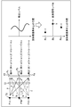
- the light sources L1 to L3 in the upper diagram of FIG. 1A are point light sources PA, PB, and PC as shown in the upper left part of FIG. It is assumed that the light beams having the light intensities a, b, and c are incident on the positions Pa, Pb, and Pc on the image sensor 11 that is incident.
- the detection sensitivity of each pixel is directed according to the incident angle by modulating the incident light from the openings 51a that are randomly set on the mask 51. Will have sex.
- providing the detection sensitivity of each pixel with the incident angle directivity means that the light receiving sensitivity characteristic according to the incident angle of the incident light differs depending on the region on the image sensor 11. is there.
- the light source constituting the subject surface 71 is a point light source
- the image sensor 11 When it is assumed that the light source constituting the subject surface 71 is a point light source, in the image sensor 11, light beams having the same light intensity emitted from the same point light source are incident.
- the incident angle changes for each region on the imaging surface of the image sensor 11. Since the incident angle of incident light is changed according to the area on the image sensor 11 by the mask 51, the light receiving sensitivity characteristic, that is, the incident angle directivity is obtained.
- detection is performed with different sensitivities for each region on the image sensor 11 by the mask 51 provided in the previous stage of the imaging surface of the image sensor 11, and detection signals having different detection signal levels are detected for each region.
- pixel detection signal levels DA, DB, and DC at positions Pa, Pb, and Pc on the image sensor 11 are expressed by the following equations (1) to (1), respectively. It is represented by (3).
- DA ⁇ 1 ⁇ a + ⁇ 1 ⁇ b + ⁇ 1 ⁇ c
- DB ⁇ 2 ⁇ a + ⁇ 2 ⁇ b + ⁇ 2 ⁇ c
- DC ⁇ 3 ⁇ a + ⁇ 3 ⁇ b + ⁇ 3 ⁇ c
- ⁇ 1 is a coefficient for the detection signal level a set in accordance with the incident angle of the light beam from the point light source PA on the object surface 71 to be restored at the position Pa on the image sensor 11.
- ⁇ 1 is a coefficient for the detection signal level b set in accordance with the incident angle of the light beam from the point light source PB on the object surface 71 to be restored at the position Pa on the image sensor 11.
- ⁇ 1 is a coefficient for the detection signal level c set in accordance with the incident angle of the light beam from the point light source PC on the object surface 71 to be restored at the position Pa on the image sensor 11.
- ( ⁇ 1 ⁇ a) in the detection signal level DA is a value indicating the detection signal level due to the light beam from the point light source PA at the position Pc.
- ( ⁇ 1 ⁇ b) of the detection signal level DA is a value indicating the detection signal level due to the light beam from the point light source PB at the position Pc.
- ( ⁇ 1 ⁇ c) of the detection signal level DA is a value indicating the detection signal level due to the light beam from the point light source PC at the position Pc.
- the detection signal level DA is expressed as a composite value obtained by multiplying each component of the point light sources PA, PB, PC at the position Pa by the respective coefficients ⁇ 1, ⁇ 1, ⁇ 1.
- the coefficients ⁇ 1, ⁇ 1, and ⁇ 1 are collectively referred to as a coefficient set.
- the coefficient sets ⁇ 2, ⁇ 2, and ⁇ 2 correspond to the coefficient sets ⁇ 1, ⁇ 1, and ⁇ 1 for the detection signal level DA in the point light source PA, respectively.
- the coefficient sets ⁇ 3, ⁇ 3, and ⁇ 3 correspond to the coefficient sets ⁇ 1, ⁇ 1, and ⁇ 1 for the detection signal level DA in the point light source PA, respectively.
- the detection signal levels of the pixels at the positions Pa, Pb, and Pc are values expressed by the product sum of the light intensities a, b, and c of the light beams emitted from the point light sources PA, PB, and PC, respectively. It is. For this reason, these detection signal levels are a mixture of the light intensities a, b, and c of the light beams emitted from the point light sources PA, PB, and PC, respectively, so that the image of the subject is formed. Is different.
- the coefficient sets ⁇ 1, ⁇ 1, ⁇ 1, the coefficient sets ⁇ 2, ⁇ 2, ⁇ 2, the coefficient sets ⁇ 3, ⁇ 3, ⁇ 3 and the simultaneous equations using the detection signal levels DA, DB, DC are constructed, and the light intensities a, b , C, the pixel values at the respective positions Pa, Pb, Pc are obtained as shown in the lower right part of FIG.
- a restored image (final image) that is a set of pixel values is reconstructed and restored.
- the coefficient set ⁇ 1, ⁇ 1, ⁇ 1, coefficient set ⁇ 2, ⁇ 2, ⁇ 2, coefficient set ⁇ 3, ⁇ 3, ⁇ 3 is each of these changes, but by changing this coefficient set, it is possible to reconstruct restored images (final images) of subject surfaces at various distances.
- the detection signal level shown in the upper right part of FIG. 2 is not a pixel value because it is not a detection signal level corresponding to an image on which an image of the subject is formed.
- the detection signal level shown in the lower right part of FIG. 2 is a signal value for each pixel corresponding to the image on which the subject image is formed, that is, the value of each pixel of the restored image (final image). Become.
- Such a configuration makes it possible to realize a so-called lensless camera that does not require an imaging lens or a pinhole.
- an imaging lens, a pinhole, or the like is not an essential configuration, it is possible to reduce the height of the imaging apparatus, that is, to reduce the thickness with respect to the incident direction of light in a configuration that realizes an imaging function.
- by changing the coefficient set in various ways it is possible to reconstruct and restore the restored image (final image) on the subject plane at various distances.
- an image taken by the image sensor and before reconstruction is simply referred to as an observation image, and an image that is reconstructed and restored by signal processing of the observation image is a restored image (final image). ). Accordingly, by changing the coefficient set described above from one observation image, images on the subject surface 71 at various distances can be reconstructed as the final image.
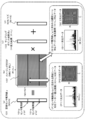
- FIG. 3 is a diagram illustrating a configuration example of an image sensor in a lensless camera.
- the upper part is a top view of the mask 51
- the lower part is a perspective view of the mask 51 and the image sensor (solid-state imaging device) 11 as seen from above the side surface.
- the image sensor of a general lensless camera has a unit size of an opening 51a in a mask 51 that is set uniformly over the entire region.
- One image is captured as a whole from the light transmitted through 51.
- FIG. 4 is a diagram showing a schematic configuration of the lensless camera 80.
- the lensless camera 80 has a configuration in which a mask 82 is disposed in front of the image sensor 81.
- the mask 82 is a mask in which a light transmission region and a light transmission region are set as a two-dimensional pattern. Light through this mask 82 is input to the image sensor.
- FIG. 4 shows a configuration example in which the subject 85 is photographed and a restored image (final image) 87 in which the subject image is restored is output.
- the pre-reconstructed image captured by the image sensor (solid-state imaging device) 81 is the observation image 86, and is reconstructed and restored by performing signal processing on the observation image 86 by the signal processing unit 83.
- the image to be processed is a restored image (final image) 87.
- the restored image (final image) 87 is an image including the subject of the shooting scene, as in a normal lens-mounted camera.
- the image (observation image 86) is taken by the image sensor 81 through the mask 82.
- the imaging data through the mask 82 that is, the observation image 86 on the image sensor 1 is input to the signal processing unit 83.
- the signal processing unit 83 performs predetermined signal processing on the observation image 86 on the image sensor 81, so that a restored image (final image) as a two-dimensional image corresponding to a shooting scene similar to a general camera is obtained. 87 is generated.
- the signal processing in the signal processing unit 83 that generates the restored image 87 that reproduces the actual scene from the observation image 86 on the image sensor 81 it is necessary to perform processing in consideration of various shooting conditions. Specifically, for example, (1) Geometric position of the image sensor with respect to the subject, (2) intensity of light output from the subject, spectral characteristics, (3) modulation by mask, (4) Position of mask and sensor, geometric relationship, (5) Spectral sensitivity characteristics of the sensor, It is necessary to execute signal processing in consideration of these imaging conditions.
- the influence on the final image (restored image) with respect to the physical change is large, and it is difficult to handle as a known value in the system.
- the restored image may be destroyed. Therefore, it is necessary to perform processing in consideration of the position and geometric relationship between the mask and image sensor unique to each lensless camera.
- the observation signal y of the image sensor 81 of the lensless camera 80 is a signal obtained by adding noise n to light obtained by modulating the scene vector (x) of the shooting scene by the imaging matrix F. Become.
- FIG. 5 shows a lensless camera 80, a signal processing unit 83, and a restored image 87 similar to those in FIG.
- the lensless camera 81 includes an image sensor 81 and a mask 82.
- the image sensor 81 is a sensor having an M ⁇ N pixel configuration of horizontal N pixels and vertical M pixels.
- the lensless camera 80 captures an image of an imaging area including trees and people.
- a restored image 87 including trees and people is generated by the image restoration process of the signal processing unit.
- the resolution of the restored image 87 is a resolution of K ⁇ L pixels of horizontal L pixels and vertical K pixels.
- the resolution of the restored image 87 depends on the signal processing in the signal processing unit 83. Specifically, it depends on how much the emitted light from the photographic subject is subdivided and analyzed.
- a shooting scene 90 shown in FIG. 5 is a two-dimensional plane set in a region through which radiated light from a subject passes.
- the two-dimensional plane is a two-dimensional plane parallel to the image sensor 81, and light incident on the image sensor 81 from the subject passes through the two-dimensional plane.
- a restored image 87 is a reproduction of the subject light passing through the two-dimensional plane.
- the signal processing unit 83 calculates the radiated light x in units of sampling points on the shooting scene 90 on the two-dimensional plane shown in FIG. 5 and sets the pixel value of the restored image 87.
- the number of sampling points on the shooting scene 90 on the two-dimensional plane is horizontal L and vertical K K ⁇ L.
- the signal processing unit 83 inputs the output of the image sensor 81 having the M ⁇ N pixel configuration of the lensless camera 80, that is, the observation image obtained through the mask 81, and samples K ⁇ L samples on the shooting scene 90.
- the point radiated light is analyzed, and a restored image 87 having a resolution of K ⁇ L pixels of horizontal L pixels and vertical K pixels is generated.
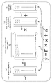
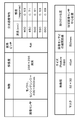
- the image sensor observation value y101 is an MN row and one column composed of observation values (y (1), y (2),... Y (MN)) of each pixel of the M ⁇ N image sensor. Is a matrix of
- the noise n104 is noise corresponding to each pixel of the M ⁇ N image sensor, and is configured by the noise value (n (1), n (2),... N (MN)) of each pixel. MN row, 1 column matrix.
- the imaging matrix F is a two-dimensional matrix having the number of dimensions of (MxN) x (KxL).
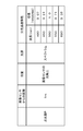
- each row element of the imaging matrix F means light from each point in the scene that reaches one pixel of the image sensor 81 via the mask 82. The meaning of the elements in each row of the imaging matrix F will be described with reference to FIG.
- FIG. 7 shows (a) two observation values included in the image sensor observation value y101.
- Sensor observation value y (p) 101p Sensor observation value y (q) 101q, The recording positions of these two sensor observation values are shown.
- the sensor observation value y (p) 101p is an element of the p th row of the matrix constituting the image sensor observation value y 101 (a), and the observation value (p) of the p th pixel of the image sensor 81 composed of MN pixels ( Pixel value).
- the sensor observation value y (q) 101q is an element of the qth row of the matrix constituting (a) the image sensor observation value y101, and the observation value (q) of the qth pixel of the image sensor 81 composed of MN pixels ( Pixel value).
- (P1) is one-dimensional data, and the values of KL elements in the row (p-th row) of “(b) imaging matrix F102” are shown as a graph.
- the horizontal axis is the axis indicating the element position from the first column at the left end to the KL column at the right end of the row (p-th row) of “(b) imaging matrix F102”.
- the vertical axis represents the light intensity. That is, it is data obtained by graphing radiated light components of KL sampling points included in the sensor observation value y (p) 101p.
- (P2) is two-dimensional data
- (P1) KL data recorded in the one-dimensional data is expanded on a two-dimensional plane having a resolution equivalent to a restored image of horizontal L pixels and vertical K pixels. Is.
- (Q1) is one-dimensional data, and the values of KL elements in the row (q-th row) of “(b) imaging matrix F102” are shown as a graph.
- the horizontal axis is an axis indicating the element positions from the first column at the left end to the KL column at the right end of the row (q-th row) of “(b) imaging matrix F102”.
- the vertical axis represents the light intensity. That is, it is data obtained by graphing the radiated light components of KL sampling points included in the sensor observation value y (q) 101q.
- (Q2) is two-dimensional data
- (K1) KL data recorded in the one-dimensional data are expanded on a two-dimensional plane having a resolution equivalent to a restored image of horizontal L pixels and vertical K pixels. Is.
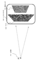
- FIG. 8 is a diagram illustrating a usage image of the lensless camera.
- the physical quantity elements related to the imaging matrix F will be described with reference to FIG.
- One attention point A, 111 is set in the shooting scene 110.
- the attention points A and 111 are one point of the subject that enters the lensless camera 120 with light having the spectral characteristic Xp and the intensity Ik from the position (x, y, z).
- Mg is the mask geometry
- Mp is the geometric position of the mask with respect to the sensor
- Sp is the spectral sensitivity characteristic of the image sensor 122
- j is the pixel identifier of the image sensor, It is.
- the imaging matrix F is given by the function G of each parameter included in (Equation 2), that is, among the components of the imaging matrix F, the image
- the matrix component F (j) of the corresponding row of the sensor pixel j is defined by (Equation 3) below.
- F (j) G (x, y, z, Xp, Mg, Mp, Sp, j) (Expression 3) It is.
- the imaging matrix F changes depending on the values of the parameters (x, y, z, Xp, Mg, Mp, Sp, j) included in the function G.
- Coordinates (x, y, z) indicating the light emission position of the light at the point of interest; Spectral characteristics Xp of the light at the point of interest, These depend on the shooting scene.
- Mask shape Mg is also a known value.
- the positional relationship Mp with respect to the sensor of the mask is a camera-specific value that differs for each lensless camera. That is, for example, when a sensor and a mask are attached to each camera in a manufacturing process of a lensless camera, variation occurs for each manufactured camera.
- the positional relationship Mp with respect to the sensor of the mask becomes a different value for each camera unit, and the value is precisely acquired, and a camera-specific imaging matrix F is generated based on the acquired value, or common.
- Correction processing specific to the camera such as correction processing using a correction matrix, is necessary.
- the spectral sensitivity characteristic Sp of the image sensor 122 since a known value can be used in almost cases, there is no need for correction based on this. However, for example, when the image sensor is a microbolometer, the observed spectral characteristic may change depending on the temperature of the sensor itself, and the correction corresponding to the spectral sensitivity characteristic Sp of the image sensor 122 may be performed.
- (S01) A captured image of a point light source (a point light source observation image by an image sensor) is acquired by a lensless camera to be calibrated.
- (B) Spectral sensitivity characteristic Sp of the image sensor Includes these parameters.
- This calibration process utilizes the fact that when only one point light source is imaged with a lensless camera, an image that directly reflects the geometric shape of the mask pattern is observed.
- the distance between the lensless camera and the point light source is changed to obtain the imaging matrix F corresponding to the subject distance or the correction matrix corresponding to the distance. It is possible.
- a diffraction phenomenon caused by a mask When generating a simulation image, it is preferable to consider a diffraction phenomenon caused by a mask if possible.
- the diffraction phenomenon occurs depending on the mask geometry, specifically the size of the slit through which light passes.
- the distance d between the center portion of the image sensor and the center portion of the mask changes, the influence of diffraction on the image on the image sensor changes greatly, and a simulation image incorporating a diffraction phenomenon according to this distance d. Is preferably generated.
- a generally known diffraction model for the simulation of the diffraction phenomenon.
- a Fresnel diffraction model which is a typical diffraction model.
- FIG. 9 shows the process of the first step (S01) in the calibration process, that is, (S01) An observation image of a point light source (a point light source observation image by an image sensor) is acquired by a lensless camera to be calibrated, It is a figure which shows the example of execution of this picked-up image acquisition process.
- Point light sources P and 151 are arranged on the front of the lensless camera 120, on the extension of the optical axis connecting the center of the sensor and the center of the assumed position of the mask.
- the lensless camera 120 includes an image sensor 121 and a mask 122, and the light from the point light sources P and 151 enters the image sensor 122 through the opening of the mask 122.
- the point light source 151 has the following specifications.
- Distance from image sensor 1m
- Position on the optical axis of the image sensor
- Light source spectrum
- Step S102 Next, in step S102, a simulation image (reference image) using initial parameters is generated.
- the simulation image (reference image) is image data output from the image sensor when it is assumed that the point light source 151 shown in FIG. 9 is captured by a lensless camera having an ideal parameter configuration.
- the initial parameter is a reference parameter defined in advance.
- the parameter Mp reference parameter Mp
- the parameter Mp reference parameter Mp is used when it is assumed that the mask is accurately attached to the sensor at a predetermined reference position.
- Spectral sensitivity characteristic Sp of the image sensor also for this parameter, a predetermined reference parameter Sp is set as an initial parameter to generate a simulation image (reference image).
- an evaluation function (SSIM: Structural Similarity) is used as the image difference evaluation process between the captured image and the simulation image.
- SSIM is an image difference evaluation function indicating a value closer to 0 as the image difference is larger and closer to 1 as the image difference is smaller.
- FIG. 13 (S103) shows an example of a simulation image (correction reference image) in which the difference from the photographed image searched in step S103 is minimized.
- the simulation image generated in step S102 is translated by applying a predetermined translation parameter T, and further rotated by applying a predetermined rotation parameter R. It is the produced
- SSIM is an image difference evaluation function indicating a value closer to 0 as the image difference is larger and closer to 1 as the image difference is smaller.
- the difference evaluation is performed by the parallel movement and rotation processing of the simulation image in step S103.
- the value of the function SSIM approaches 1, indicating that the difference from the photographed image has decreased.
- the search for the simulation image that minimizes the difference from the captured image that is, the search process for the parameter d is performed by applying, for example, a coarse-fine search process.
- the coarse-fine type search process is a search process that initially searches at coarse intervals and gradually decreases the search width.
- Step S106 The processes in the next steps S106 to S107 are optional processes and can be omitted. These processes are (B) Spectral sensitivity characteristic Sp of the image sensor This is executed when calculating a correction value for.
- the parameter to be optimized is the spectral sensitivity characteristic Sp.
- a plurality of simulation images are generated by changing the value of the parameter Sp at a certain interval.
- Step S107 a photographed image is selected from a plurality of simulation images (correction reference images) generated according to a plurality of different spectral sensitivity characteristics Sp (Sp1, Sp2, Sp3... Spn) generated in step S106.
- a simulation image (correction reference image) that minimizes the difference is searched for and its spectral sensitivity characteristic Sp is obtained.
- Parameter Sp correction amount (0.6, 0.65, 0.75, 0.65, 0.59) This parameter correction amount.
- the SSIM is an image difference evaluation function indicating a value closer to 0 as the image difference is larger and closer to 1 as the image difference is smaller.
- the simulation image in step S107 is more than the simulation image generated in step S105.
- the value of the difference evaluation function SSIM approaches 1, indicating that the difference from the captured image has decreased.
- step S108 If it is determined that the threshold value is higher than the predetermined threshold, the process is terminated. If it is not equal to or greater than the predetermined threshold value, the processes in and after step S102 are repeatedly executed. Finally, if it is determined in step S108 that the threshold value is equal to or greater than a predetermined threshold value, the process is terminated.
- step S108 the value of the difference evaluation function SSIM indicating the difference between the simulation image generated in step S105 and the actual captured image acquired in step S101 is set in advance. Processing is performed to determine whether or not the threshold value is exceeded.
- step S108 determines whether the threshold value is equal to or greater than a predetermined threshold value.
- Step S107 Spectral sensitivity characteristic Sp of image sensor This parameter is data indicating the characteristics of the lensless camera currently being calibrated.
- these data are stored in the memory of the lensless camera to be calibrated.
- the lensless camera calculates an imaging matrix F by using data (correction parameters) stored in a memory when generating a restored image for a captured image, so that an optimum image according to the actual configuration of the camera is obtained.
- the imaging matrix F can be calculated.
- the geometrical position Mp for the sensor of the parameter mask included in these equations, Spectral sensitivity characteristic Sp of image sensor, are stored in the memory of each camera as parameters according to the configuration and characteristics unique to each camera calculated according to the flow shown in FIG.
- the lensless camera calculates an imaging matrix F by using data (correction parameters) stored in a memory when generating a restored image for a captured image, so that an optimum image according to the actual configuration of the camera is obtained.
- the imaging matrix F can be calculated.
- the camera-specific corrected imaging matrix F may be calculated in advance using the camera-specific parameters (Mp, SP), and the corrected imaging matrix F may be stored in the memory.
- a common imaging matrix F is stored in each camera, and a correction matrix for converting the common imaging matrix F into a camera-specific imaging matrix F that reflects (Mp, SP) a parameter specific to each camera. It is good also as a structure which calculates and stores in the memory of each camera.
- the correspondence between the observation value y of the image sensor of the lensless camera and the imaging matrix F is expressed by the following (Equation 1).
- y Fx + n (Formula 1)
- y Image sensor observation value
- F Imaging matrix
- n noise
- the inverse matrix F ⁇ 1 of the imaging matrix F is used.
- a configuration may be adopted in which the inverse matrix F ⁇ 1 of the imaging matrix F reflecting the parameters unique to each camera is stored in advance in the memory of each camera.
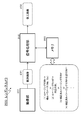
- FIG. 14 is a block diagram illustrating an apparatus configuration example when processing according to the flow illustrated in FIG. 12 is executed.
- the lensless camera 200 to be calibrated and the calibration processing execution device 210 are connected.
- the lensless camera 200 has a mask and an image sensor, and receives light through the mask with the image sensor.
- the lensless camera 200 outputs the point light source captured image 211 obtained by capturing the point light source to the calibration device 210 as described above with reference to FIG.
- the calibration apparatus 210 executes the processes of steps S102 to S108 in the flowchart described above with reference to FIG. That is, first, a simulation image (reference image) that is assumed to be imaged when a point light source is imaged by a reference lensless camera having an ideal configuration and setting by applying the initial parameter (reference parameter) 212. Is generated.
- the simulation image correction process starts with Rotation parameter R, Translation parameter T, A simulation image (correction reference image) in which these values are sequentially changed is generated.
- a simulation image (correction reference image) in which the value of the mask-image sensor distance parameter d is sequentially changed is generated. From this simulation image (correction reference image), an image closest to the point light source image 211 is selected, and the mask-image sensor distance parameter d applied to the selected simulation image, Hold.
- a changed simulation image (correction reference image) is sequentially generated by changing the spectral sensitivity characteristic Sp of the image sensor. From this simulation image (correction reference image), the one closest to the point light source image 211 is selected, and the spectral sensitivity characteristic Sp applied to the selected simulation image is expressed as follows: Hold.
- the above process is repeated until the SSIM indicating the difference between the point light source captured image 211 and the simulation image (correction reference image) becomes equal to or greater than a specified threshold value.
- the process is terminated, and the correction parameter obtained at this time is output. It is stored in the memory of the camera 200.
- the correction parameters to be output are (A) A parameter indicating the positional relationship Mp of the mask with respect to the sensor. Rotation parameter R, Translation parameter T, Mask-image sensor distance parameter d These parameters. When the spectral sensitivity characteristic Sp of the image sensor is also calculated, This parameter is also output.
- FIG. 15 is a block diagram illustrating a configuration example of the lensless camera 200.
- the lensless camera 200 includes an imaging unit 201, a signal processing unit 202, and a memory 203.
- the imaging unit 201 has a configuration in which a mask is arranged in front of the image sensor, as described above with reference to FIG.
- the mask is a mask in which a light transmission region and a light transmission region are set as a two-dimensional pattern. Light through this mask is input to the image sensor.
- the observation image 231 captured by the image sensor of the imaging unit 201 is input to the signal processing unit 202.
- the signal processing unit 202 performs signal processing on the observed image 231 and outputs a restored image 232.
- the restored image (final image) 232 is an image including the subject of the shooting scene, like a normal lens-mounted camera.
- the imaging matrix F uses a unique matrix generated by a unique parameter of the lensless camera 200. That is, (A) the positional relationship Mp of the mask with respect to the sensor; (B) Spectral sensitivity characteristic Sp of the image sensor, These parameters are camera-specific parameters, and a correct restored image 232 can be generated by using the camera-specific imaging matrix F and the inverse matrix F ⁇ 1 generated by applying the parameters. Become.
- the correction matrix reflecting the camera-specific correction parameters (Mp, SP,%) In (2) is a camera-specific correction parameter (Mp, SP,%) Obtained by multiplying the common imaging matrix F.
- This is a matrix that can be converted into a camera-specific imaging matrix F generated by applying (-).
- the number of pixels of the image sensor is MN
- the number of sampling points in the shooting scene is KL.
- the pixel value of the pixel value y ij in the i-th column and the j-th row of the image sensor can be expressed as the following (Expression 16).
- variables (a, b, c, d) are set under the conditions shown in the following (formula 18).
- the lensless camera can execute correct image restoration processing according to the configuration and characteristics unique to the lensless camera using the data stored in the memory.
- a pointless light source is photographed once by a lensless camera (or a plurality of times at which the distance is changed), and the geometry of the mask and the sensor is determined by comparing the photographed image with the simulation image. It is possible to acquire an imaging matrix G that best reflects the physical positional relationship, this correction matrix, or camera-specific correction parameters.
- FIG. 16 is a configuration example of a calibration processing execution device (calibration processing execution device 210 shown in FIG. 14) that executes the calibration processing described above with reference to FIG. . Moreover, it is also an example of a hardware configuration that executes the processing of the signal processing unit 202 of the lensless camera 200 shown in FIG.
- a CPU (Central Processing Unit) 501 functions as a control unit or a data processing unit that executes various processes according to a program stored in a ROM (Read Only Memory) 502 or a storage unit 508. For example, processing according to the sequence described in the above-described embodiment is executed.
- a RAM (Random Access Memory) 503 stores programs executed by the CPU 501 and data.
- the CPU 501, ROM 502, and RAM 503 are connected to each other by a bus 504.
- the CPU 501 is connected to an input / output interface 505 via a bus 504.
- An input unit 506 including various switches, a keyboard, a mouse, a microphone, and a sensor, and an output unit 507 including a display and a speaker are connected to the input / output interface 505.
- the CPU 501 executes various processes in response to a command input from the input unit 506 and outputs a processing result to the output unit 507, for example.
- the storage unit 508 connected to the input / output interface 505 includes, for example, a hard disk and stores programs executed by the CPU 501 and various data.
- a communication unit 509 functions as a transmission / reception unit for Wi-Fi communication, Bluetooth (BT) communication, and other data communication via a network such as the Internet or a local area network, and communicates with an external device.
- BT Bluetooth
- the drive 510 connected to the input / output interface 505 drives a removable medium 511 such as a magnetic disk, an optical disk, a magneto-optical disk, or a semiconductor memory such as a memory card, and executes data recording or reading.
- a removable medium 511 such as a magnetic disk, an optical disk, a magneto-optical disk, or a semiconductor memory such as a memory card
- the technology disclosed in this specification can take the following configurations. (1) It has a signal processing part which inputs the picked-up image which is an output of the image sensor of a lensless camera, and produces
- the said signal processing part is a position of the mask and image sensor of the said lensless camera at least An image processing apparatus that generates the restored image by image processing to which camera-specific data generated based on relationship information is applied.
- the camera-specific data is data generated by a comparison process between a photographed image obtained by photographing one point light source in front of the optical axis of the lensless camera and a reference image.
- Image processing device
- the reference image is estimated to be acquired by photographing one point light source in front of the optical axis of the lensless camera when the positional relationship between the mask of the lensless camera and the image sensor is at the reference position.
- the image processing apparatus according to (2) which is a simulation image.
- the camera-specific data is The image processing apparatus according to (3) or (4), which is data detected by performing a correction process on the simulation image and generating a simulation image in which a difference from the captured image is reduced.
- the positional relationship data Mp is Rotation parameter R for the image sensor of the mask, Translational parameter T for mask image sensor, A distance parameter d between the center of the image sensor and the center of the mask, The image processing apparatus according to (6), which includes these three parameters.
- the camera-specific data is (A) positional relationship data Mp with respect to the image sensor of the mask of the lensless camera; (B) Spectral sensitivity characteristic data Sp of the image sensor, The image processing apparatus according to any one of (1) to (7), including each of the above data.
- the signal processing unit The image processing apparatus according to any one of (1) to (8), wherein the restored image is generated by image processing using an imaging matrix F common to a plurality of lensless cameras and the camera-specific data.
- the signal processing unit The image processing apparatus according to any one of (1) to (9), wherein the restored image is generated by image processing using a camera-specific imaging matrix F corrected by applying the camera-specific data.
- the signal processing unit The restored image is generated based on the relationship between the camera-specific imaging matrix F corrected by applying the camera-specific data and the observation value y of the image sensor (1) to (10). Image processing device.
- the camera-specific data is Data generated by a comparison process between a captured image obtained by photographing one point light source in front of the optical axis of the lensless camera and a reference image, Camera-specific data corresponding to a plurality of different subject distances obtained by processing using a captured image corresponding to a distance obtained by changing the distance between the lensless camera and the point light source and a simulation image, or an imaging matrix F, or The image processing device according to any one of (1) to (11), which is a correction matrix.
- the camera-specific data is (A) positional relationship data Mp with respect to the image sensor of the mask of the lensless camera; (B) Spectral sensitivity characteristic data Sp of the image sensor, The image processing device according to (13) or (14), which includes each of the above data.
- the image processing apparatus includes: Processing using a captured image corresponding to a distance obtained by changing the distance between the lensless camera and the point light source and a simulation image is executed, and camera-specific data corresponding to different subject distances, or an imaging matrix F, or a correction matrix
- the image processing device according to any one of (13) to (15).
- a mask in which a light transmission region and a light transmission region are set as a two-dimensional pattern
- An imaging unit that includes an image sensor that receives light through the mask, a camera that is generated by a comparison process between a captured image obtained by imaging one point light source in front of the optical axis of the imaging unit, and a reference image A memory that stores unique data; and a signal processing unit that inputs a captured image that is an output of the image sensor to generate a restored image, and the signal processing unit stores the camera specific data stored in the memory.
- An imaging apparatus that generates the restored image by applied image processing.
- An image processing method executed in an image processing apparatus the image processing apparatus having a signal processing unit that inputs a captured image that is an output of an image sensor of a lensless camera and generates a restored image
- An image processing method for performing a lensless camera calibration process executed in an image processing apparatus wherein the image processing apparatus obtains a captured image obtained by photographing one point light source in front of the optical axis of the lensless camera;
- a simulation image that is estimated to be acquired by photographing one point light source in front of the optical axis of the lensless camera is input.
- the series of processes described in the specification can be executed by hardware, software, or a combined configuration of both.
- the program recording the processing sequence is installed in a memory in a computer incorporated in dedicated hardware and executed, or the program is executed on a general-purpose computer capable of executing various processing. It can be installed and run.
- the program can be recorded in advance on a recording medium.
- the program can be received via a network such as a LAN (Local Area Network) or the Internet and installed on a recording medium such as a built-in hard disk.
- the various processes described in the specification are not only executed in time series according to the description, but may be executed in parallel or individually according to the processing capability of the apparatus that executes the processes or as necessary.
- the system is a logical set configuration of a plurality of devices, and the devices of each configuration are not limited to being in the same casing.
- a highly accurate restored image is generated by image processing that reflects camera-specific data such as positional relationship information between a lensless camera mask and an image sensor.
- a configuration that enables this is realized.
Landscapes
- Engineering & Computer Science (AREA)
- Multimedia (AREA)
- Signal Processing (AREA)
- Theoretical Computer Science (AREA)
- Physics & Mathematics (AREA)
- General Physics & Mathematics (AREA)
- Computing Systems (AREA)
- Image Processing (AREA)
- Studio Devices (AREA)
Abstract
レンズレスカメラのマスクと画像センサとの位置関係情報等のカメラ固有データを反映した画像処理により高精度な復元画像の生成を可能とした構成を実現する。レンズレスカメラの画像センサの出力である撮影画像を入力して復元画像を生成する信号処理部を有し、信号処理部は、少なくともレンズレスカメラのマスクと画像センサとの位置関係情報に基づいて生成されるカメラ固有データを適用した画像処理により復元画像の生成を行う。カメラ固有データは、レンズレスカメラの光軸前方の1つの点光源の撮影によって得られる撮影画像と、基準画像との比較処理によって生成されたデータであり、基準画像はマスクと画像センサとの位置関係が基準位置にある場合に取得されると推定されるシミュレーション画像である。
Description
本開示は、画像処理装置、および撮像装置、並びに画像処理方法に関する。特に、レンズレスカメラ(レンズレス撮像装置)や、レンズレスカメラのキャリブレーションを行う画像処理装置、および撮像装置、並びに画像処理方法に関する。
近年、レンズを利用せずに画像を撮影可能としたレンズレスカメラの開発が進んでいる。従来の一般的なカメラは、レンズを介した光を撮像素子である画像センサに入力して画像を撮影するが、レンズレスカメラは、レンズの代わりに、光の透過領域と不透過領域を2次元パターンや、回折格子などの光を変調する機構を持つマスクを用い、マスクを介した光を画像センサに入力する。画像センサにはマスクを介した像が撮影される。このマスクを介した撮像データに対して、所定の信号処理を行うことで、一般的なカメラと同様の撮影シーンに対応する2次元画像を生成することができる。レンズレスカメラは、レンズが不要であるため、撮像装置の小型化、軽量化、廉価化、非平面化等を実現することができる。
上述したように、レンズレスカメラは、マスクを介した光を画像センサに入力する。シーン(撮影シーン)からの放射光が、マスクを介してどのようにセンサ上に投影されるかの情報を、あらかじめマトリックスとして定義しておき、そのマトリックスとセンサ上に投影された画像(観測画像)から、実際のシーンを再現した画像(復元画像)を生成することができる。
なお、レンズレスカメラについては、例えば、以下の文献に記載がある。
特許文献1(国際公開WO2016/123529号公報)、
特許文献1(国際公開WO2016/123529号公報)、
レンズレスカメラの画像センサにおいて検出される信号(観測信号)に対する信号処理を行い、実際のシーンを再現した画像(復元画像)を生成する場合には、様々な撮影条件を考慮した処理が必要となる。
具体的には、例えば、
(1)被写体に対する画像センサの幾何的な位置、
(2)被写体から出力される光の強度、分光特性、
(3)マスクによる変調、
(4)マスクとセンサの位置、幾何関係、
(5)センサの分光感度特性、
これらの撮影条件を考慮した信号処理を実行することが必要となる。
具体的には、例えば、
(1)被写体に対する画像センサの幾何的な位置、
(2)被写体から出力される光の強度、分光特性、
(3)マスクによる変調、
(4)マスクとセンサの位置、幾何関係、
(5)センサの分光感度特性、
これらの撮影条件を考慮した信号処理を実行することが必要となる。
特に、マスクと画像センサの位置、幾何関係については、その物理量の変化が最終画像(復元画像)に大きな影響を与える。しかし、レンズレスカメラの生産工程において、マスクやセンサの取り付け位置のばらつきをゼロにすることは不可能であり、各カメラ単位のばらつきが発生する。
従って、生産されたレンズレスカメラ各々に正しい復元画像を生成、出力させるためには、各レンズレスカメラ固有のマスクと画像センサの位置関係を反映した処理を行わせることが必要となる。マスクと画像センサの位置や幾何関係を実際のものと異なる想定で信号処理を行い、復元画像を生成した場合、復元画像は破たんしてしまう場合がある。
上記特許文献1においては、その対策として、レンズレスカメラの前にディスプレイ装置(例えば可視光におけるLCD)を配置し、レンズレスカメラに様々な縦横の直線パターンを提示することで、マスクとセンサの位置、幾何関係を補正するための行列式を算出する構成を開示している。
この方法は、ノイズや回折ぼけに対して頑健性の優れた方法である。しかしその反面、提示するパターン数が非常に大量になるという問題がある。例えば、画素数NxNの画像を得るレンズレスカメラシステムに対しては、2N回の直線パターンの撮像が必要となる。従って、多数のレンズレスカメラの生産ラインで各カメラ対応の補正行列を算出するためには、レンズレスカメラ1台ごとに膨大な数の直線パターンの撮像を実行することが必要となり、処理時間が膨大となってしまう。
また、多種類の直線パターンの提示処理を行うための装置(ディスプレイ)についてもコスト高を招く要因がある。例えばレンズレスカメラが可視光画像を撮影するカメラであれば、可視光を出力するLCDなどの安価なディスプレイが使用可能であるが、例えば赤外光を利用する場合など、可視光以外の帯域を利用する場合はコストが大きくなる。この場合、多種類の直線パターンの出力を行う装置(ディスプレイ)は、赤外光出力型の装置(ディスプレイ)であることが必要となる。例えば1000μm~の短赤外以上の波長帯域の赤外光出力型の装置(ディスプレイ)を多数、設置するためには、相当のコストが発生するという問題がある。
本開示は、例えば、上記の問題点に鑑みてなされたものであり、多種類の直線パターンの提示処理を行うことなく、レンズレスカメラのキャリブレーションを行い、マスクやセンサの取り付け位置のばらつき等に応じた最適な処理を可能とした画像処理装置、および撮像装置、並びに画像処理方法を提供することを目的とする。
本開示の第1の側面は、レンズレスカメラの画像センサの出力である撮影画像を入力して復元画像を生成する信号処理部を有し、前記信号処理部は、少なくとも前記レンズレスカメラのマスクと画像センサとの位置関係情報に基づいて生成されるカメラ固有データを適用した画像処理により、前記復元画像の生成を行う画像処理装置にある。
さらに、本開示の第2の側面は、レンズレスカメラの光軸前方の1つの点光源の撮影によって得られる撮影画像と、前記レンズレスカメラのマスクと画像センサとの位置関係が基準位置にある場合に、レンズレスカメラの光軸前方の1つの点光源の撮影によって取得されると推定されるシミュレーション画像を入力し、前記シミュレーション画像に対する補正処理を行い、前記撮影画像との差分が小さくなる補正シミュレーション画像を選択し、前記補正シミュレーション画像に適用した補正データに基づいて、前記レンズレスカメラにおける画像復元処理に適用可能なカメラ固有データを生成するキャリブレーション処理を実行する画像処理装置にある。
さらに、本開示の第3の側面は、光の透過領域と不透過領域を2次元パターンとして設定したマスクと、前記マスクを介した光を受光する画像センサとからなる撮像部と、前記撮像部の光軸前方の1つの点光源の撮影によって得られる撮影画像と、基準画像との比較処理によって生成されたカメラ固有データを格納したメモリと、前記画像センサの出力である撮影画像を入力して復元画像を生成する信号処理部を有し、前記信号処理部は、前記メモリに格納された前記カメラ固有データを適用した画像処理により前記復元画像の生成を行う撮像装置にある。
さらに、本開示の第4の側面は、画像処理装置において実行する画像処理方法であり、前記画像処理装置は、レンズレスカメラの画像センサの出力である撮影画像を入力して復元画像を生成する信号処理部を有し、前記信号処理部が、少なくとも前記レンズレスカメラのマスクと画像センサとの位置関係情報に基づいて生成されるカメラ固有データを適用した画像処理により、前記復元画像の生成を行う画像処理方法にある。
さらに、本開示の第5の側面は、画像処理装置において実行するレンズレスカメラのキャリブレーション処理を行う画像処理方法であり、前記画像処理装置が、レンズレスカメラの光軸前方の1つの点光源の撮影によって得られる撮影画像と、前記レンズレスカメラのマスクと画像センサとの位置関係が基準位置にある場合に、レンズレスカメラの光軸前方の1つの点光源の撮影によって取得されると推定されるシミュレーション画像を入力し、前記シミュレーション画像に対する補正処理を行い、前記撮影画像との差分が小さくなる補正シミュレーション画像を選択し、前記補正シミュレーション画像に適用した補正データに基づいて、前記レンズレスカメラにおける画像復元処理に適用可能なカメラ固有データを生成するキャリブレーション処理を実行する画像処理方法にある。
なお、本開示のさらに他の目的、特徴や利点は、後述する本開示の実施例や添付する図面に基づくより詳細な説明によって明らかになるであろう。なお、本明細書においてシステムとは、複数の装置の論理的集合構成であり、各構成の装置が同一筐体内にあるものには限らない。
本開示の一実施例の構成によれば、レンズレスカメラのマスクと画像センサとの位置関係情報等のカメラ固有データを反映した画像処理により高精度な復元画像の生成を可能とした構成を実現する。なお、本明細書に記載された効果はあくまで例示であって限定されるものではなく、また付加的な効果があってもよい。
以下、図面を参照しながら本開示の画像処理装置、および撮像装置、並びに画像処理方法の詳細について説明する。なお、説明は以下の項目に従って行う。
1.レンズレスカメラの概要と原理について
2.レンズレスカメラの観測画像から復元画像を生成する信号処理について
3.イメージング行列Fに関連する物理量について
4.カメラキャリブレーション処理の詳細について
5.キャリブレーション処理を実行する装置、およびカメラの構成例について
6.計算処理を簡略化した処理例について
7.本開示の画像処理の効果について
8.画像処理装置のハードウェア構成例について
9.本開示の構成のまとめ
1.レンズレスカメラの概要と原理について
2.レンズレスカメラの観測画像から復元画像を生成する信号処理について
3.イメージング行列Fに関連する物理量について
4.カメラキャリブレーション処理の詳細について
5.キャリブレーション処理を実行する装置、およびカメラの構成例について
6.計算処理を簡略化した処理例について
7.本開示の画像処理の効果について
8.画像処理装置のハードウェア構成例について
9.本開示の構成のまとめ
[1.レンズレスカメラの概要と原理について]
まず、レンズレスカメラの概要と原理について説明する。図1、図2を参照して、一般的なカメラ(撮像装置)の構成との比較により、レンズレスカメラ(レンズレス撮像装置)の概要について説明する。図1には、
(a)レンズレスカメラ
(b)レンズありカメラ
(c)ピンホールカメラ
これらの3種類のカメラの撮像原理を示している。
まず、レンズレスカメラの概要と原理について説明する。図1、図2を参照して、一般的なカメラ(撮像装置)の構成との比較により、レンズレスカメラ(レンズレス撮像装置)の概要について説明する。図1には、
(a)レンズレスカメラ
(b)レンズありカメラ
(c)ピンホールカメラ
これらの3種類のカメラの撮像原理を示している。
(c)ピンホールカメラは、遮光膜12に対して穴部として設けられたピンホール21と画像センサ(個体撮像素子)11から構成される。ピンホールからなる撮像装置の場合、図1右下部の(c)ピンホールカメラの図に示すように、被写体面上のそれぞれ異なる光源から発せられる光線L1乃至L3が、それぞれピンホール21を透過して画像センサ(個体撮像素子)11上の画素I1乃至I3に像として撮像される。
ピンホールカメラからなる撮像装置の場合、画像センサ(個体撮像素子)11においては、光源のそれぞれから発せられた光線L1乃至L3のうちの1画素分の光線のみにより、像が結像されて画像センサ(個体撮像素子)11上の各画素に入射されることになるので暗い画像として撮像される。
図1右上部の(b)レンズありカメラは、遮光膜31の中央に撮像レンズ32を設け、撮像レンズ32が、光線L1乃至L3を、光線I11乃至I13で示されるように集光し、画像センサ(個体撮像素子)11上にそれぞれの像を結像し、これが画像センサ(個体撮像素子)11により撮像される設定としている。
図1右上部の(b)レンズありカメラの場合、画像センサ(個体撮像素子)11は、光線L1乃至L3の全ての光強度の合計である光強度の光からなる像が結像されて画像センサ(個体撮像素子)11に入射されるので、画像センサ(個体撮像素子)11の各画素において十分な光量の画像が撮像される。
図1右上部の(b)レンズありカメラの図に示すように、撮像レンズ32を用いることにより、点光源のそれぞれの集合が被写体を構成することになる。従って、被写体の撮像は、被写体面上の複数の点光源から発せられる光線が集光されて結像される被写体を撮像することになる。
図1右上部の(b)レンズありカメラを参照して説明したように、撮像レンズ32の役割は点光源のそれぞれから出射される各光線、即ち拡散光を、画像センサ(個体撮像素子)11上に導くことにある。そのため、画像センサ(個体撮像素子)11上には最終画像相当の像が結像されることとなり、画像センサ(個体撮像素子)11上の各画素において検出される検出信号からなる画像が、像が結像された観測画像となる。
しかしながら、撮像レンズと撮像レンズの焦点距離によって撮像装置(撮像素子)のサイズが決定されるため、小型化には限界があった。
これに対して、図1左側に示す(a)レンズレスカメラは、撮像レンズやピンホールを設けることなく、画像センサ(個体撮像素子)11とマスク51を用いて、被写体面上の被写体を撮像する。
図1左側に示す(a)レンズレスカメラは、画像センサ11の前段に複数のサイズの開口部51aを備えたマスク51が設けられており、光源のそれぞれからの光線L1乃至L3が変調されて画像センサ11の撮像面に入射し、画像センサ(個体撮像素子)11上の各画素により受光される。
ここで、マスク51は、開口部51aと遮光部51bとが、図1(a)レンズレスカメラの下部に示すように、単位サイズΔの単位で水平方向および垂直方向について、大きさがランダムに設定されたマスクパターンを持つマスクである。単位サイズΔは、少なくとも画素サイズよりも大きいサイズである。また、画像センサ11とマスク51との間には、微小な距離dの隙間が設けられている。図に示す例では、画像センサ11上の画素間のピッチがwとされている。のような構成により、単位サイズΔと距離dとのサイズにより光線L1乃至L3は、画像センサ11上に変調されて入射する。
より詳細には、図1(a)レンズレスカメラの上図における光線L1乃至L3の光源を、例えば、図2の左上部に示すように、点光源PA,PB,PCとし、マスク51を透過して入射する画像センサ11上の位置Pa,Pb,Pcのそれぞれに光強度a,b,cの光線が入射するものとする。
レンズレスカメラの場合、図2左上部に示すように、各画素の検出感度は、マスク51に、ランダムに設定される開口部51aより入射光が変調されることにより、入射角に応じた指向性を持つことになる。ここでいう各画素の検出感度に入射角指向性を持たせるとは、画像センサ11上の領域に応じて入射光の入射角度に応じた受光感度特性を異なるものとなるように持たせることである。
すなわち、被写体面71を構成する光源が点光源であることを前提とした場合、画像センサ11においては、同一の点光源より発せられた同一の光強度の光線が、入射されることになるが、マスク51により変調されることにより、画像センサ11の撮像面上の領域毎に入射角度が変化する。そして、マスク51により画像センサ11上の領域に応じて入射光の入射角度が変化することにより受光感度特性、すなわち、入射角指向性を有しているので、同一の光強度の光線であっても、画像センサ11の撮像面の前段に設けられたマスク51により画像センサ11上の領域毎に異なる感度で検出されることになり、領域毎に異なる検出信号レベルの検出信号が検出される。
より具体的には、図2の右上部で示されるように、画像センサ11上の位置Pa,Pb,Pcにおける画素の検出信号レベルDA,DB,DCは、それぞれ以下の式(1)乃至式(3)で表される。
DA=α1×a+β1×b+γ1×c ・・・(1)
DB=α2×a+β2×b+γ2×c ・・・(2)
DC=α3×a+β3×b+γ3×c ・・・(3)
DB=α2×a+β2×b+γ2×c ・・・(2)
DC=α3×a+β3×b+γ3×c ・・・(3)
ここで、α1は、画像センサ11上の位置Paにおける復元する被写体面71上の点光源PAからの光線の入射角度に応じて設定される検出信号レベルaに対する係数である。
また、β1は、画像センサ11上の位置Paにおける復元する被写体面71上の点光源PBからの光線の入射角度に応じて設定される検出信号レベルbに対する係数である。
さらに、γ1は、画像センサ11上の位置Paにおける復元する被写体面71上の点光源PCからの光線の入射角度に応じて設定される検出信号レベルcに対する係数である。
また、β1は、画像センサ11上の位置Paにおける復元する被写体面71上の点光源PBからの光線の入射角度に応じて設定される検出信号レベルbに対する係数である。
さらに、γ1は、画像センサ11上の位置Paにおける復元する被写体面71上の点光源PCからの光線の入射角度に応じて設定される検出信号レベルcに対する係数である。
従って、検出信号レベルDAのうちの(α1×a)は、位置Pcにおける点光源PAからの光線による検出信号レベルを示す値となる。
また、検出信号レベルDAのうちの(β1×b)は、位置Pcにおける点光源PBからの光線による検出信号レベルを示す値となる。
さらに、検出信号レベルDAのうちの(γ1×c)は、位置Pcにおける点光源PCからの光線による検出信号レベルを示す値となる。
また、検出信号レベルDAのうちの(β1×b)は、位置Pcにおける点光源PBからの光線による検出信号レベルを示す値となる。
さらに、検出信号レベルDAのうちの(γ1×c)は、位置Pcにおける点光源PCからの光線による検出信号レベルを示す値となる。
従って、検出信号レベルDAは、位置Paにおける点光源PA,PB,PCの各成分に、それぞれの係数α1,β1,γ1を掛けたものの合成値として表現される。
以降、係数α1、β1、γ1を合わせて係数セットと呼ぶこととする。
以降、係数α1、β1、γ1を合わせて係数セットと呼ぶこととする。
同様に、点光源PBにおける検出信号レベルDBについて、係数セットα2,β2,γ2は、それぞれ点光源PAにおける検出信号レベルDAについての、係数セットα1,β1,γ1に対応するものである。
また、点光源PCにおける検出信号レベルDCについて、係数セットα3,β3,γ3は、それぞれ点光源PAにおける検出信号レベルDAについての、係数セットα1,β1,γ1に対応するものである。
また、点光源PCにおける検出信号レベルDCについて、係数セットα3,β3,γ3は、それぞれ点光源PAにおける検出信号レベルDAについての、係数セットα1,β1,γ1に対応するものである。
ただし、位置Pa,Pb,Pcの画素の検出信号レベルについては、点光源PA,PB,PCのそれぞれより発せられた光線の光強度a,b,cと係数との積和により表現される値である。このため、これらの検出信号レベルは、点光源PA,PB,PCのそれぞれより発せられた光線の光強度a,b,cが入り交じったものとなるので、被写体の像が結像されたものとは異なるものである。
すなわち、この係数セットα1,β1,γ1,係数セットα2,β2,γ2,係数セットα3,β3,γ3と、検出信号レベルDA,DB,DCを用いた連立方程式を構成し、光強度a,b,cを解くことで、図1の右下部で示されるように各位置Pa,Pb,Pcの画素値を求める。これにより画素値の集合である復元画像(最終画像)が再構成されて復元される。
また、図2の左上部で示される画像センサ11と被写体面71との距離が変化する場合、係数セットα1,β1,γ1,係数セットα2,β2,γ2,係数セットα3,β3,γ3は、それぞれ変化することになるが、この係数セットを変化させることで、様々な距離の被写体面の復元画像(最終画像)を再構成させることができる。
このため、1回の撮像により、係数セットを様々な距離に対応するものに変化させることで、撮像位置から様々な距離の被写体面の画像を再構成することができる。
結果として、レンズレスカメラを用いた撮像においては、レンズを用いた撮像装置での撮像において合焦点がずれた状態で撮像される、いわゆる、ピンぼけといった現象を意識する必要がなく、画角内に撮像したい被写体が含まれるように撮像されていれば、距離に応じた係数セットを変化させることで様々な距離の被写体面の画像を、撮像後に再構成することができる。
なお、図2の右上部に示す検出信号レベルは、被写体の像が結像された画像に対応する検出信号レベルではないので、画素値ではない。また、図2の右下部に示す検出信号レベルは、被写体の像が結像された画像に対応する画素毎の信号値、すなわち、復元画像(最終画像)の各画素の値なので、画素値となる。
このような構成により、撮像レンズや、ピンホールを必要としない、いわゆるレンズレスカメラを実現することが可能となる。結果として、撮像レンズや、ピンホール等が必須構成とならないので、撮像装置の低背化、すなわち、撮像機能を実現する構成における光の入射方向に対する厚さを薄くすることが可能になる。また、係数セットを様々に変化させることにより、様々な距離の被写体面における復元画像(最終画像)を再構成して復元することが可能となる。
なお、以降においては、画像センサにより撮像された、再構成される前の画像を単に観測画像と称し、観測画像が信号処理されることにより再構成されて復元される画像を復元画像(最終画像)と称する。従って、1枚の観測画像からは、上述した係数セットを様々に変化させることにより、様々な距離の被写体面71上の画像を最終画像として再構成させることができる。
図3は、レンズレスカメラにおける撮像素子の構成例を示す図である。上部がマスク51の上面図であり、下部がマスク51と画像センサ(固体撮像素子)11とを側面上方からみた斜視図である。
一般的なレンズレスカメラの撮像素子は、例えば、図3に示すように、マスク51における開口部51aの単位サイズが、全領域に対して一様に設定されて、画像センサ11においては、マスク51を透過した光より全体として1枚の画像が撮像される。
[2.レンズレスカメラの観測画像から復元画像を生成する信号処理について]
次に、レンズレスカメラの観測画像から復元画像を生成する信号処理について説明する。図4は、レンズレスカメラ80の概略構成を示す図である。図4に示すようにレンズレスカメラ80は、画像センサ81の前にマスク82を配置した構成を持つ。マスク82は、光の透過領域と不透過領域を2次元パターンとして設定したマスクである。このマスク82を介した光を画像センサに入力する。
次に、レンズレスカメラの観測画像から復元画像を生成する信号処理について説明する。図4は、レンズレスカメラ80の概略構成を示す図である。図4に示すようにレンズレスカメラ80は、画像センサ81の前にマスク82を配置した構成を持つ。マスク82は、光の透過領域と不透過領域を2次元パターンとして設定したマスクである。このマスク82を介した光を画像センサに入力する。
図4では、被写体85の撮影を行い、被写体画像が復元された復元画像(最終画像)87を出力する構成例を示している。なお、画像センサ(固体撮像素子)81により撮像された再構成される前の画像が観測画像86であり、信号処理部83が観測画像86に対して信号処理を行うことで再構成されて復元される画像が復元画像(最終画像)87である。復元画像(最終画像)87は、通常のレンズ装着カメラと同様、撮影シーンの被写体を含む画像となる。
画像センサ81にはマスク82を介した像(観測画像86)が撮影される。マスク82を介した撮像データ、すなわち画像センサ1上の観測画像86が信号処理部83に入力される。信号処理部83は、画像センサ81上の観測画像86に対して、所定の信号処理を行うことで、一般的なカメラと同様の撮影シーンに対応する2次元画像としての復元画像(最終画像)87を生成する。
画像センサ81上の観測画像86から実際のシーンを再現した復元画像87を生成する信号処理部83における信号処理に際しては、様々な撮影条件を考慮した処理を行うことが必要である。具体的には、例えば、
(1)被写体に対する画像センサの幾何的な位置、
(2)被写体から出力される光の強度、分光特性、
(3)マスクによる変調、
(4)マスクとセンサの位置、幾何関係、
(5)センサの分光感度特性、
これらの撮影条件を考慮した信号処理を実行することが必要となる。
(1)被写体に対する画像センサの幾何的な位置、
(2)被写体から出力される光の強度、分光特性、
(3)マスクによる変調、
(4)マスクとセンサの位置、幾何関係、
(5)センサの分光感度特性、
これらの撮影条件を考慮した信号処理を実行することが必要となる。
特に、マスクと画像センサの位置、幾何関係については、その物理的な変化に対する最終画像(復元画像)への影響が大きく、システムにおける既知の値として扱うことが困難である。マスクと画像センサの位置や幾何関係を実際のものと異なる想定で信号処理を行い、復元画像を生成した場合、復元画像は破たんしてしまう場合がある。そのため、各レンズレスカメラ固有のマスクと画像センサの位置や幾何関係を考慮した処理が必要となる。
図4に示すレンズレスカメラ80による観測画像の撮影原理を定式化すると、以下の(式1)によって表現することができる。
y=Fx+n ・・・(式1)
ただし、
y:画像センサ81の観測信号(1次元化データ)
x:シーンベクトル(撮影シーンの放射光の値(1次元化データ))
n:ノイズ
F:イメージング行列(Imaging Matrix)
y=Fx+n ・・・(式1)
ただし、
y:画像センサ81の観測信号(1次元化データ)
x:シーンベクトル(撮影シーンの放射光の値(1次元化データ))
n:ノイズ
F:イメージング行列(Imaging Matrix)
なお、xは、撮影シーンの放射光の値であり、復元画像87の画素値にも相当する。復元画像87は、撮影シーンの放射光の値を再現した画像に相当するからである。
上記(式1)から理解されるように、レンズレスカメラ80の画像センサ81の観測信号yは、撮影シーンのシーンベクトル(x)をイメージング行列Fによって変調した光にノイズnを付加した信号となる。
上記(式1)から理解されるように、レンズレスカメラ80の画像センサ81の観測信号yは、撮影シーンのシーンベクトル(x)をイメージング行列Fによって変調した光にノイズnを付加した信号となる。
図5以下を参照して、上記(式1)の詳細について説明する。図5には、図4と同様のレンズレスカメラ80、信号処理部83、復元画像87を示している。レンズレスカメラ81は、画像センサ81、マスク82を有する。画像センサ81は、図に示すように、水平N画素、垂直M画素のM×N画素構成からなるセンサである。
図5に示す例において、レンズレスカメラ80は、木や人を含む撮影領域の画像を撮影する。最終的には、信号処理部の画像復元処理によって木や人を含む復元画像87が生成される。この復元画像87の解像度は、水平L画素、垂直K画素のK×L画素の解像度である。
復元画像87の解像度は、信号処理部83における信号処理に依存する。具体的には、撮影被写体からの放射光をどれだけ細分化して解析するかに依存する。図5に示す撮影シーン90は、被写体からの放射光の通過領域に設定した2次元平面である。この2次元平面は、画像センサ81に平行な2次元平面であり、被写体から画像センサ81に入射する光はこの2次元平面を通過する。この2次元平面を通過する被写体光を再現したものが復元画像87となる。
図に示す2次元平面上の撮影シーン90に示す複数の丸印をサンプリングポイントとし、このサンプリングポイントの放射光が、上記(式1)、すなわち、
y=Fx+n ・・・(式1)
この(式1)のx(撮影シーンの放射光の値)に相当する。このxを再現することで、復元画像の各画素の値が決定される。すなわち、信号処理部83は、図5に示す2次元平面上の撮影シーン90上のサンプリングポイント単位の放射光xを算出して、復元画像87の画素値を設定する。
y=Fx+n ・・・(式1)
この(式1)のx(撮影シーンの放射光の値)に相当する。このxを再現することで、復元画像の各画素の値が決定される。すなわち、信号処理部83は、図5に示す2次元平面上の撮影シーン90上のサンプリングポイント単位の放射光xを算出して、復元画像87の画素値を設定する。
図に示す例では、2次元平面上の撮影シーン90上のサンプリングポイントは、水平L個、垂直K個のK×L個である。信号処理部83は、レンズレスカメラ80のM×N画素構成からなる画像センサ81の出力、すなわちマスク81を介して得られる観測画像を入力して、撮影シーン90上のK×L個のサンプリングポイントの放射光を解析し、水平L画素、垂直K画素のK×L画素の解像度からなる復元画像87を生成する。
次に、図6を参照して、前述した(式1)、すなわち、
y=Fx+n ・・・(式1)
上記(式1)の具体的な計算処理例について説明する。
y=Fx+n ・・・(式1)
上記(式1)の具体的な計算処理例について説明する。
図6には、上記(式1)を構成する各データ行列形式に表現した計算式を示している。すなわち、
(a)画像センサ観測値y101、
(b)イメージング行列F102、
(c)シーンベクトルx(サンプリングポイント放射光(=復元画像))103、
(d)ノイズn104
これらの4つのデータである。
(a)画像センサ観測値y101、
(b)イメージング行列F102、
(c)シーンベクトルx(サンプリングポイント放射光(=復元画像))103、
(d)ノイズn104
これらの4つのデータである。
(a)画像センサ観測値y101は、M×Nの画像センサの各画素の観測値(y(1),y(2),・・・y(MN))によって構成されるMN行、1列の行列となる。
(b)イメージング行列F102は、(a)画像センサ観測値y101と、(c)シーンベクトルx(サンプリングポイント放射光(=復元画像))103との対応関係情報からなる行列であり、MN行、KL列の行列となる。
(b)イメージング行列F102と、(c)シーンベクトルx(サンプリングポイント放射光(=復元画像))103との乗算結果+(d)ノイズn104が、(a)画像センサ観測値y101、すなわち画像センサのMN画素の各画素値となる。
なお、(a)画像センサ観測値y101から、復元画像のKL画素の画素値を算出する場合は、イメージング行列F102の逆行列が利用される。
(b)イメージング行列F102と、(c)シーンベクトルx(サンプリングポイント放射光(=復元画像))103との乗算結果+(d)ノイズn104が、(a)画像センサ観測値y101、すなわち画像センサのMN画素の各画素値となる。
なお、(a)画像センサ観測値y101から、復元画像のKL画素の画素値を算出する場合は、イメージング行列F102の逆行列が利用される。
(c)シーンベクトルx(サンプリングポイント放射光(=復元画像))103は、図5を参照して説明した2次元平面の撮影シーン90に設定したサンプリングポイントの数、すなわち復元画像87の画素数に等しいKL個の要素(x(1),x(2),・・・x(KL))によって構成されるKL行、1列の行列となる。
(d)ノイズn104は、M×Nの画像センサの各画素対応のノイズであり、各画素のノイズの値(n(1),n(2),・・・n(MN))によって構成されるMN行、1列の行列となる。
(d)ノイズn104は、M×Nの画像センサの各画素対応のノイズであり、各画素のノイズの値(n(1),n(2),・・・n(MN))によって構成されるMN行、1列の行列となる。
このように、上述した(式1)、すなわち、
y=Fx+n ・・・(式1)
この(式1)の演算は、図6に示す行列の演算を行うことを意味する。
y=Fx+n ・・・(式1)
この(式1)の演算は、図6に示す行列の演算を行うことを意味する。
画像センサ81の画素数がMN画素であり、復元画像の解像度をKL画素としたとき、イメージング行列Fは、(MxN)x(KxL)の次元数を持った2次元行列となる。
シーンベクトルxに、イメージング行列Fを乗算し、MxN次元のノイズベクトルnを加算したものが、画像センサ81上の各画素の値の一次元データからなる観測ベクトルyとなる。なお、イメージング行列Fの各行の要素は、マスク82を介して、画像センサ81のある1画素に到達するシーン中の各点からの光を意味する。イメージング行列Fの各行の要素の意味について、図7を参照して説明する。
図7には、図6と同様、前述した、(式1)を構成する各データを簡略化して示している。すなわち、
(a)画像センサ観測値y101、
(b)イメージング行列F102、
(c)シーンベクトルx(サンプリングポイント放射光(=復元画像))103、
(d)ノイズn104
これらの4つのデータである。
(a)画像センサ観測値y101、
(b)イメージング行列F102、
(c)シーンベクトルx(サンプリングポイント放射光(=復元画像))103、
(d)ノイズn104
これらの4つのデータである。
図7には、(a)画像センサ観測値y101に含まれる2つの観測値である、
センサ観測値y(p)101p、
センサ観測値y(q)101q、
これら2つのセンサ観測値の記録位置を示している。
センサ観測値y(p)101pは、(a)画像センサ観測値y101を構成する行列のp番目の行の要素であり、MN画素から構成される画像センサ81のp番目の画素の観測値(画素値)である。
センサ観測値y(q)101qは、(a)画像センサ観測値y101を構成する行列のq番目の行の要素であり、MN画素から構成される画像センサ81のq番目の画素の観測値(画素値)である。
センサ観測値y(p)101p、
センサ観測値y(q)101q、
これら2つのセンサ観測値の記録位置を示している。
センサ観測値y(p)101pは、(a)画像センサ観測値y101を構成する行列のp番目の行の要素であり、MN画素から構成される画像センサ81のp番目の画素の観測値(画素値)である。
センサ観測値y(q)101qは、(a)画像センサ観測値y101を構成する行列のq番目の行の要素であり、MN画素から構成される画像センサ81のq番目の画素の観測値(画素値)である。
画像センサ81の各画素には、図5を参照して説明した撮影シーン90の様々なサンプリングポイントからの放射光が入射する。すなわち、センサ観測値y(p)101p、センサ観測値y(q)101q、いずれも、図5に示すKL個のサンプリングポイント内の複数のサンプリングポイントからの放射光を入射している。
(a)画像センサ観測値y101を構成する行列のセンサ観測値y(p)101pの記録行に対応する「(b)イメージング行列F102」の行(p番目の行)には、このセンサ観測値y(p)101pに含まれるKL個のサンプリングポイント各々の出力光成分が記録される。この(b)イメージング行列F102の行のデータの具体例は、図7の下部左側に示す、
(P)センサ観測値y(p)に含まれる撮影シーン対応データ(=復元画像)(K×L)対応データである。
(P)センサ観測値y(p)に含まれる撮影シーン対応データ(=復元画像)(K×L)対応データである。
(P1)は、1次元データであり、「(b)イメージング行列F102」の行(p番目の行)のKL個の要素の値をグラフとして示している。横軸が「(b)イメージング行列F102」の行(p番目の行)の左端の第1列から右端のKL列の要素位置を示す軸である。縦軸が光強度を示している。すなわち、センサ観測値y(p)101pに含まれるKL個のサンプリングポイントの放射光成分をグラフ化したデータである。
(P2)は、2次元データであり、水平方向L画素、垂直方向K画素の復元画像相当の解像度を持つ2次元平面に、(P1)1次元データに記録されたKL個のデータを展開したものである。
また、(a)画像センサ観測値y101を構成する行列のもう1つのセンサ観測値y(q)101qの記録行に対応する「(b)イメージング行列F102」の行(q番目の行)には、このセンサ観測値y(q)101qに含まれるKL個のサンプリングポイント各々の出力光成分が記録される。この(b)イメージング行列F102の行のデータの具体例は、図7の下部右側に示す、(Q)センサ観測値y(q)に含まれる撮影シーン対応データ(=復元画像)(K×L)対応データである。
(Q1)は、1次元データであり、「(b)イメージング行列F102」の行(q番目の行)のKL個の要素の値をグラフとして示している。横軸が「(b)イメージング行列F102」の行(q番目の行)の左端の第1列から右端のKL列の要素位置を示す軸である。縦軸が光強度を示している。すなわち、センサ観測値y(q)101qに含まれるKL個のサンプリングポイントの放射光成分をグラフ化したデータである。
(Q2)は、2次元データであり、水平方向L画素、垂直方向K画素の復元画像相当の解像度を持つ2次元平面に、(Q1)1次元データに記録されたKL個のデータを展開したものである。
(P1),(Q2)には、「(b)イメージング行列F102」の2つの行のサンプリングポイントの放射光成分の2次元データを示しているが、「(b)イメージング行列F102」の全ての行(MN行)のサンプリングポイントの放射光成分の2次元データを重畳すると、復元画像87が生成される。
ちなみに、上述した(式1)、すなわち、
y=Fx+n
この撮像システムの原理式は、レンズレスカメラのみならず、従来のレンズを用いた撮像、拡散板を介した撮像などでも用いることは可能である。レンズレスカメラにおいては、イメージング行列Fに、マスクによる変調およびマスクとセンサの位置・幾何関係が関係していることが、異なるポイントである。
y=Fx+n
この撮像システムの原理式は、レンズレスカメラのみならず、従来のレンズを用いた撮像、拡散板を介した撮像などでも用いることは可能である。レンズレスカメラにおいては、イメージング行列Fに、マスクによる変調およびマスクとセンサの位置・幾何関係が関係していることが、異なるポイントである。
[3.イメージング行列Fに関連する物理量について]
次に、イメージング行列Fに関連する物理量について説明する。図8は、レンズレスカメラの使用イメージを示す図である。
次に、イメージング行列Fに関連する物理量について説明する。図8は、レンズレスカメラの使用イメージを示す図である。
図8を用いて、イメージング行列Fに関連する物理量の要素について説明する。撮影シーン110内に1つの注目点A,111を設定する。注目点A,111は、位置(x,y,z)から、分光特性Xp、強度Ikの光をレンズレスカメラ120に入光する被写体の1つの点である。
このとき、レンズレスカメラ120の画像センサ122のある画素jが観測する観測値値Y(j)は、以下の(式2)、すなわち、
Y(j)=G(x,y,z,Xp,Mg,Mp,Sp,j)×Ik、・・(式2)
上記(式2)で表すことができる。
Y(j)=G(x,y,z,Xp,Mg,Mp,Sp,j)×Ik、・・(式2)
上記(式2)で表すことができる。
ここで、
Mgはマスクの幾何形状、
Mpはマスクのセンサに対する幾何的な位置、
Spは、画像センサ122の分光感度特性、
jは、画像ゼンサの画素識別子、
である。
Mgはマスクの幾何形状、
Mpはマスクのセンサに対する幾何的な位置、
Spは、画像センサ122の分光感度特性、
jは、画像ゼンサの画素識別子、
である。
先に説明したレンズレスカメラによる観測画像の撮影原理を示す式である、
y=Fx+n ・・・(式1)
ただし、
y:画像センサ81の観測信号(1次元化データ)
x:シーンベクトル(撮影シーンの放射光の値(1次元化データ))
n:ノイズ
F:イメージング行列(Imaging Matrix)
y=Fx+n ・・・(式1)
ただし、
y:画像センサ81の観測信号(1次元化データ)
x:シーンベクトル(撮影シーンの放射光の値(1次元化データ))
n:ノイズ
F:イメージング行列(Imaging Matrix)
上記(式1)と、(式2)から、イメージング行列Fは、(式2)に含まれる各パラメータの関数Gにより与えられると言い換えることができる、すなわち、イメージング行列Fの構成要素中、画像センサの画素jの対応行の行列構成要素F(j)は以下の(式3)によって定義される。
F(j)=G(x,y,z,Xp,Mg,Mp,Sp,j)・・・(式3)
である。
F(j)=G(x,y,z,Xp,Mg,Mp,Sp,j)・・・(式3)
である。
上記(式3)から言えることは、関数Gに含まれるパラメータ(x,y,z,Xp,Mg,Mp,Sp,j)の値によって、イメージング行列Fが変化するということである。これらのパラメータのうち、
注目点の光の発光位置を示す座標(x,y,z),
注目点の光の分光特性Xp、
これらは、撮影シーンに依存するものである。
また、
マスクの形状Mgも既知の値である。
注目点の光の発光位置を示す座標(x,y,z),
注目点の光の分光特性Xp、
これらは、撮影シーンに依存するものである。
また、
マスクの形状Mgも既知の値である。
マスクのセンサに対する位置関係Mpは、レンズレスカメラごとに異なるカメラ固有の値となる。すなわち、例えばレンズレスカメラの製造工程において、各カメラに対して、センサの取り付けと、マスクの取り付けを行う場合、製造されるカメラごとにばらつきが発生する。
従って、マスクのセンサに対する位置関係Mpについては、各カメラ単位で異なる値となり、精緻にその値を取得して、その取得値に基づいて、カメラ固有のイメージング行列Fを生成するか、あるいは、共通のイメージング行列Fに対するカメラ固有の補正処理、例えば補正行列による補正処理を行う等、何らかの補正処理が必要となる。
このような補正処理を行わずにイメージング行列Fを適用した処理、あるいはその逆行列を利用して復元画像の生成処理を実行しても正常な復元画像が生成できず破たんした復元画像が生成されることになる。
なお、画像センサ122の分光感度特性Spについては、概ねのケースで既知の値を用いることができるため、これに基づく補正の必要はない。ただし、例えば、画像センサがマイクロボロメータの場合などは、観測分光特性はセンサ自身の温度等によって変化することもあり、画像センサ122の分光感度特性Spに対応した補正を行う構成としてもよい。
[4.カメラキャリブレーション処理の詳細について]
上述したように、イメージング行列Fに影響を与えるンズレスカメラ固有のパラメータとして、以下の2つのパラメータがある。
(a)マスクのセンサに対する位置関係Mp、
(b)画像センサの分光感度特性Sp、
これらのばらつきを考慮せずに、すべてのカメラに共通のイメージング行列Fやその逆行列を利用した復元画像の生成処理を行ってしまうと、正常な復元画像の生成ができなくなる。この問題を解決するためのカメラキャリブレーション処理の具体例について説明する。
上述したように、イメージング行列Fに影響を与えるンズレスカメラ固有のパラメータとして、以下の2つのパラメータがある。
(a)マスクのセンサに対する位置関係Mp、
(b)画像センサの分光感度特性Sp、
これらのばらつきを考慮せずに、すべてのカメラに共通のイメージング行列Fやその逆行列を利用した復元画像の生成処理を行ってしまうと、正常な復元画像の生成ができなくなる。この問題を解決するためのカメラキャリブレーション処理の具体例について説明する。
以下において説明するカメラキャリブレーション処理の概要は以下の通りである。
(S01)キャリブレーション対象となるレンズレスカメラによって、点光源の撮影画像(画像センサによる点光源観測画像)を取得。
(S02)規定の基準パラメータの設定された理想的なカメラ(基準カメラ)による点光源の撮影画像(画像センサによる点光源観測画像)(=基準画像)をシミュレーションにより生成。
なお、規定の基準パラメータには、
(a)マスクのセンサに対する位置関係Mp、
(b)画像センサの分光感度特性Sp、
これらのパラメータを含む。
(S01)キャリブレーション対象となるレンズレスカメラによって、点光源の撮影画像(画像センサによる点光源観測画像)を取得。
(S02)規定の基準パラメータの設定された理想的なカメラ(基準カメラ)による点光源の撮影画像(画像センサによる点光源観測画像)(=基準画像)をシミュレーションにより生成。
なお、規定の基準パラメータには、
(a)マスクのセンサに対する位置関係Mp、
(b)画像センサの分光感度特性Sp、
これらのパラメータを含む。
(S03)シミュレーション画像(基準画像)に対して、イメージング行列Fに影響の影響のるカメラ固有のパラメータ、すなわち、
(a)マスクのセンサに対する位置関係Mp、
(b)画像センサの分光感度特性Sp、
これらのパラメータを順次、変更したシミュレーション画像(補正基準画像)を生成、
(S04)シミュレーション画像(補正基準画像)と、撮影画像との比較によって、カメラ固有の理想的なパラメータを取得、
本開示の処理において実行するカメラキャリブレーション処理の概要は上述の処理(S01)~(S04)である。
(a)マスクのセンサに対する位置関係Mp、
(b)画像センサの分光感度特性Sp、
これらのパラメータを順次、変更したシミュレーション画像(補正基準画像)を生成、
(S04)シミュレーション画像(補正基準画像)と、撮影画像との比較によって、カメラ固有の理想的なパラメータを取得、
本開示の処理において実行するカメラキャリブレーション処理の概要は上述の処理(S01)~(S04)である。
このキャリブレーション処理は、1点のみの点光源をレンズレスカメラで撮像した場合、マスクパターンの幾何形状を、直接、反映した像が観測されることを利用したものである。なお、被写体距離に応じてイメージング行列Fを変更したい場合には、レンズレスカメラと点光源の距離を変えて、各距離に応じた被写体距離対応のイメージング行列F、あるいは距離対応の補正行列を求めることが可能である。
なお、シミュレーション画像の生成時には、できればマスクによる回折現象についても考慮することが好ましい。回折現象はマスクの幾何形状、具体的には光が透過するスリットの大きさなどに依存して発生する。特に、画像センサの中心部とマスクの中心部間の距離dが変化すると、画像センサ上の像に対する回折の影響が大きく変化することになり、この距離dに応じた回折現象を織り込んだシミュレーション画像を生成することが好ましい。
なお、回折現象のシミュレーションには一般に知られている回折モデルを用いることが可能である。例えば、代表的な回折モデルであるフレネル回折モデルを利用することが可能である。
なお、回折現象のシミュレーションには一般に知られている回折モデルを用いることが可能である。例えば、代表的な回折モデルであるフレネル回折モデルを利用することが可能である。
図9は、キャリブレーション処理における上記の最初のステップ(S01)の処理、すなわち、
(S01)キャリブレーション対象となるレンズレスカメラによって、点光源の観測画像(画像センサによる点光源観測画像)を取得、
この撮影画像取得処理の実行例を示す図である。
(S01)キャリブレーション対象となるレンズレスカメラによって、点光源の観測画像(画像センサによる点光源観測画像)を取得、
この撮影画像取得処理の実行例を示す図である。
点光源P,151をレンズレスカメラ120の正面、センサの中心とマスク設置想定位置の中心を結んだ光軸の延長上に配置する。レンズレスカメラ120は、画像センサ121、マスク122を有し、点光源P,151の光は、マスク122の開口部を介して画像センサ122に入射する。
実際に実行したキャリブレーション処理に利用した、
画像センサ122、
マスク121、および、
点光源151、
これら、各構成要素の仕様を、図10、図11に示す。
画像センサ122、
マスク121、および、
点光源151、
これら、各構成要素の仕様を、図10、図11に示す。
図10に示すように、
画像センサ122は、以下の仕様を持つ。
特性=モノクロセンサ、センシングレンジ=400nm~600nm、
解像度=256×256画素、
画素ピッチ=4マイクロメートル、
分光感度特性=(波長(nm),感度(response))=(400,0.53),(450,0.71),(500,0.81),(550,0.63),(600,0.69)
画像センサ122は、以下の仕様を持つ。
特性=モノクロセンサ、センシングレンジ=400nm~600nm、
解像度=256×256画素、
画素ピッチ=4マイクロメートル、
分光感度特性=(波長(nm),感度(response))=(400,0.53),(450,0.71),(500,0.81),(550,0.63),(600,0.69)
また、マスク121は、以下の仕様を持つ。
解像度=32×32
サイズ(Feature Size)=40マイクロメートル、
画像センサからの距離=約2mm
取り付け位置=ほぼ画像センサ中心位置、
解像度=32×32
サイズ(Feature Size)=40マイクロメートル、
画像センサからの距離=約2mm
取り付け位置=ほぼ画像センサ中心位置、
また、図11に示すように、
点光源151は、以下の仕様を持つ。
画像センサからの距離=1m、
位置=画像センサの光軸上、
光源(ソース)=スペクトラム、
分光感度特性=(波長(nm),感度(response))=(400,0.07),(450,0.21),(500,1.0),(550,0.71),(600,0.32)
点光源151は、以下の仕様を持つ。
画像センサからの距離=1m、
位置=画像センサの光軸上、
光源(ソース)=スペクトラム、
分光感度特性=(波長(nm),感度(response))=(400,0.07),(450,0.21),(500,1.0),(550,0.71),(600,0.32)
これらの仕様を持つ画像センサ122、マスク121によって構成されるレンズレスカメラ120と、点光源151を用いてキャリブレーション処理を実行した。なお、ここで、まず、補正したいパラメータはマスク121の幾何的な位置Mpである。
マスクの幾何的な位置Mpは、複数の要素を持つ。まず、マスクの幾何的位置Mpを以下の関数G2によって表す。
Mp=G2(R,T,d)
関数G2の入力パラメータは、
回転パラメータR,
平行移動バラメータT,
画像センサ中心とマスク中心間の距離パラメータd、
これら3つのパラメータである。
なお、回転パラメータR,平行移動バラメータTは、それぞれマスクの3次元位置を規定する(x,y,z)からなる行列に対する補正行列として表現することが可能であり、回転行列Rと、平行移動行列Tとして表現可能である。
Mp=G2(R,T,d)
関数G2の入力パラメータは、
回転パラメータR,
平行移動バラメータT,
画像センサ中心とマスク中心間の距離パラメータd、
これら3つのパラメータである。
なお、回転パラメータR,平行移動バラメータTは、それぞれマスクの3次元位置を規定する(x,y,z)からなる行列に対する補正行列として表現することが可能であり、回転行列Rと、平行移動行列Tとして表現可能である。
なお、Mp=G2(Ho,d)として、回転行列Rと、平行移動行列Tを1つの行列としたホモグラフィ(Homography)行列Hoを用いた表現としてもよい。
以下では、
回転パラメータR,
平行移動バラメータT,
画像センサ中心とマスク中心間の距離パラメータd、
これら3つのパラメータを用いた処理として説明する。
回転パラメータR,
平行移動バラメータT,
画像センサ中心とマスク中心間の距離パラメータd、
これら3つのパラメータを用いた処理として説明する。
図12に示すフローチャートに従って、本開示のキャリブレーション処理の詳細シーケンスについて説明する。
フローに示すステップS101以下の各処理について順次、説明する。
フローに示すステップS101以下の各処理について順次、説明する。
(ステップS101)
まず、ステップS101において、キャリブレーション対象となるレンズレスカメラ120により、点光源P,151を撮影する。
まず、ステップS101において、キャリブレーション対象となるレンズレスカメラ120により、点光源P,151を撮影する。
この点光源撮影画像の例を図13(S101)に示す。この画像は、図9を参照して説明した点光源151の撮影処理によって得られる画像センサ123からの出力であり、マスク122のパターンを直接的に反映した画像となる。
(ステップS102)
次に、ステップS102において、初期パラメータを利用したシミュレーション画像(基準画像)を生成する。シミュレーション画像(基準画像)は、理想的なパラメータ構成を持つレンズレスカメラによって図9に示す点光源151を撮影したと仮定した場合に画像センサから出力される画像データである。
次に、ステップS102において、初期パラメータを利用したシミュレーション画像(基準画像)を生成する。シミュレーション画像(基準画像)は、理想的なパラメータ構成を持つレンズレスカメラによって図9に示す点光源151を撮影したと仮定した場合に画像センサから出力される画像データである。
初期パラメータは、予め規定した基準パラメータである。例えば、上述した、
(a)マスクのセンサに対する位置関係Mp
については、マスクがセンサに対して規定の基準位置に正確に取り付けられていると仮定した場合のパラメータMp(基準パラメータMp)を使用する。
(a)マスクのセンサに対する位置関係Mp
については、マスクがセンサに対して規定の基準位置に正確に取り付けられていると仮定した場合のパラメータMp(基準パラメータMp)を使用する。
なお、後段で説明するオプション処理であるステップS106~S107の処理を行う場合は、
(b)画像センサの分光感度特性Sp、
このパラメータについても、予め規定した基準パラメータSpを初期パラメータとして設定してシミュレーション画像(基準画像)を生成する。
(b)画像センサの分光感度特性Sp、
このパラメータについても、予め規定した基準パラメータSpを初期パラメータとして設定してシミュレーション画像(基準画像)を生成する。
このステップS102において生成されるシミュレーション画像の例を図13(S102)に示す。このシミュレーション画像は、マスクがセンサに対して予め規定した基準位置に正確に取り付けられているとの仮定、すなわちマスクのセンサに対する位置関係が理想的な位置関係であるとの仮定に基づいて生成されたシミュレーション画像であり、理想的な画像となる。
(ステップS103)
次に、ステップS103において、ステップS102で生成したシミュレーション画像に対して、様々な回転パラメータRと、平行移動パラメータTを適用したアフィン(Affine)変換、またはホモグラフィ(Homography)変換を行い、様々な回転、平行移動をさせたシミュレーション画像(補正基準画像)を生成し、これらをステップS101で取得した撮影画像と比較する。
次に、ステップS103において、ステップS102で生成したシミュレーション画像に対して、様々な回転パラメータRと、平行移動パラメータTを適用したアフィン(Affine)変換、またはホモグラフィ(Homography)変換を行い、様々な回転、平行移動をさせたシミュレーション画像(補正基準画像)を生成し、これらをステップS101で取得した撮影画像と比較する。
この比較処理によって、撮影画像との画像差分が最も小さくなるシミュレーション画像を選択し、そのシミュレーション画像に適用した回転パラメータRと、平行移動パラメータTを抽出する。
なお、撮影画像とシミュレーション画像との画像差分の評価処理としては、例えば、評価関数(SSIM:Structural Similarity)を用いる。SSIMは、画像差分が大きいほど0に近く、画像差分が小さいほど1に近い値を示す画像差分評価関数である。
このステップS103において探索された撮影画像との差分が最小となるシミュレーション画像(補正基準画像)の例を図13(S103)に示す。図13(S103)に示すシミュレーション画像は、ステップS102で生成したシミュレーション画像に対して、所定の平行移動パラメータTを適用した平行移動を行い、さらに所定の回転パラメータRを適用して回転を行って生成したシミュレーション画像である。
このシミュレーション画像は、ステップS102において生成した理想的な構成を持つカメラによって撮影されるシミュレーション画像を、実際の撮影画像(S101で取得した撮影画像)に近づける平行移動と回転を行って生成したシミュレーション画像となる。
図13の(S103)の画像の下部には、この画像を生成するために適用した補正量を示している。すなわち、
パラメータT補正量=-0.000086m,-0.000101m
パラメータR補正量=2.36°
これらのパラメータ補正量である。
パラメータT補正量=-0.000086m,-0.000101m
パラメータR補正量=2.36°
これらのパラメータ補正量である。
これらは、図13の(S103)に示すシミュレーション画像(補正基準画像)が、ステップS102で生成したシミュレーション画像(基準画像)に対して、x方向に-0.000086m,y方向に-0.000101m、平行移動を行い、時計まわりに2.36°回転させて生成したシミュレーション画像(補正基準画像)であることを意味し、この補正によって、実際の撮影画像(S101で取得した撮影画像)に最も差分の少ない画像が生成されたことを意味する。
図13に示すように、(S103)で生成したシミュレーション画像の差分評価関数は、SSIM=0.7623である。これは、(S103)で生成したシミュレーション画像(補正基準画像)と実際の撮影画像(S101で取得した撮影画像)との差分評価値である。ちなみに、図13に示す(S102)で生成した最初のシミュレーション画像(基準画像)の差分評価関数SSIMは、SSIM=0.0629である。
前述したように、SSIMは、画像差分が大きいほど0に近く、画像差分が小さいほど1に近い値を示す画像差分評価関数であり、ステップS103におけるシミュレーション画像の平行移動と回転処理により、差分評価関数SSIMの値が1に近づき、撮影画像との差分が小さくなったことを示している。
(ステップS104)
次に、ステップS104において、ステップS103で得られたシミュレーション画像(補正基準画像)、すなわち、撮影画像との差分を最小にする補正(回転パラメータRと、平行移動パラメータT)を適用したシミュレーション画像に対して、複数の異なるマスク-画像センサ距離パラメータd(d1,d2,d3・・・dn)を設定した複数のシミュレーション画像を生成する。
次に、ステップS104において、ステップS103で得られたシミュレーション画像(補正基準画像)、すなわち、撮影画像との差分を最小にする補正(回転パラメータRと、平行移動パラメータT)を適用したシミュレーション画像に対して、複数の異なるマスク-画像センサ距離パラメータd(d1,d2,d3・・・dn)を設定した複数のシミュレーション画像を生成する。
次に最適化するのはマスク-センサ間の距離dである。マスク-センサ間の距離dにより、像倍率のみならず、回折ぼけの大きさが変わるため、ある程度の間隔でパラメータdを振って複数のシミュレーション画像を生成する。
(ステップS105)
次に、ステップS105において、ステップS104で生成した複数の異なるマスク-画像センサ距離パラメータd(d1,d2,d3・・・dn)を設定して生成した複数のシミュレーション画像(補正基準画像)の中から、撮影画像との差分が最小となるシミュレーション画像を探索してそのマスク-画像センサ距離パラメータdを取得する。
次に、ステップS105において、ステップS104で生成した複数の異なるマスク-画像センサ距離パラメータd(d1,d2,d3・・・dn)を設定して生成した複数のシミュレーション画像(補正基準画像)の中から、撮影画像との差分が最小となるシミュレーション画像を探索してそのマスク-画像センサ距離パラメータdを取得する。
なお、この処理における、撮影画像との差分が最小となるシミュレーション画像の探索、すなわちパラメータdの探索処理は、例えば、コースーファイン(Coarse-Fine)型探索処理を適用して行う。
コースーファイン(Coarse-Fine)型探索処理は、最初は、粗い間隔で探索し、徐々に探索幅を小さくする探索処理である。
コースーファイン(Coarse-Fine)型探索処理は、最初は、粗い間隔で探索し、徐々に探索幅を小さくする探索処理である。
このステップS105において取得されたマスク-画像センサ距離パラメータdを適用したシミュレーション画像(補正基準画像)の例を図13(S105)に示す。
このシミュレーション画像は、ステップS103において生成したシミュレーション画像、すなわち実際の撮影画像に近い位置に平行移動と回転処理を施した後のシミュレーション画像(補正基準画像)に対して、さらに、実際の撮影画像(S101で取得した撮影画像)に近づけるように、パラメータd、すなわちマスク-画像センサ距離パラメータdを変更して再補正したシミュレーション画像(補正基準画像)となる。
このシミュレーション画像は、ステップS103において生成したシミュレーション画像、すなわち実際の撮影画像に近い位置に平行移動と回転処理を施した後のシミュレーション画像(補正基準画像)に対して、さらに、実際の撮影画像(S101で取得した撮影画像)に近づけるように、パラメータd、すなわちマスク-画像センサ距離パラメータdを変更して再補正したシミュレーション画像(補正基準画像)となる。
図13の(S105)の画像の下部には、この画像を生成するために適用した補正量を示している。すなわち、
パラメータd補正量=2.38mm
このパラメータ補正量である。
パラメータd補正量=2.38mm
このパラメータ補正量である。
これは、図13の(S105)に示すシミュレーション画像(補正基準画像)が、ステップS103で生成したシミュレーション画像に対して、マスク-画像センサ距離パラメータd=2.38mmに設定する再補正を行って生成したシミュレーション画像であることを意味し、この補正によって、実際の撮影画像(S101で取得した撮影画像)に最も差分の少ない画像が生成されたことを意味する。
図13に示すように、(S105)で生成したシミュレーション画像の差分評価関数は、SSIM=0.9487である。これは、(S105)で生成したシミュレーション画像と実際の撮影画像(S101で取得した撮影画像)との差分評価値である。ちなみに、図13に示す(S103)で生成したシミュレーション画像の差分評価関数SSIMは、SSIM=0.7623である。
前述したように、SSIMは、画像差分が大きいほど0に近く、画像差分が小さいほど1に近い値を示す画像差分評価関数であり、ステップS105におけるシミュレーション画像は、ステップS103で生成したシミュレーション画像より、差分評価関数SSIMの値が1に近づき、撮影画像との差分が小さくなったことを示している。
(ステップS106)
次のステップS106~S107の処理は、オプション処理であり、省略可能である。
これらの処理は、
(b)画像センサの分光感度特性Sp
についての補正値を算出する場合に実行する。
次のステップS106~S107の処理は、オプション処理であり、省略可能である。
これらの処理は、
(b)画像センサの分光感度特性Sp
についての補正値を算出する場合に実行する。
なお、先に説明したように、このステップS106~S107の処理を実行する場合には、ステップS102において生成するシミュレーション画像は、
(b)画像センサの分光感度特性Sp、
このパラメータを予め規定した基準パラメータSp(初期パラメータ)として設定して生成したシミュレーション画像とすることが必要である。
(b)画像センサの分光感度特性Sp、
このパラメータを予め規定した基準パラメータSp(初期パラメータ)として設定して生成したシミュレーション画像とすることが必要である。
ステップS106では、ステップS105で取得したシミュレーション画像(補正基準画像)、すなわち、撮影画像との差分を最小にする補正を行ったシミュレーション画像に対して、複数の異なる画像センサ分光感度特性Sp(Sp1,Sp2,Sp3・・・Spn)を設定した複数のシミュレーション画像を生成する。
ここで最適化対象とするパラメータは分光感度特性Spである。ある程度の間隔でパラメータSpの値を振って複数のシミュレーション画像を生成する。
(ステップS107)
次に、ステップS107において、ステップS106で生成した複数の異なる分光感度特性Sp(Sp1,Sp2,Sp3・・・Spn)に従って生成した複数のシミュレーション画像(補正基準画像)の中から、撮影画像との差分が最小となるシミュレーション画像(補正基準画像)を探索してその分光感度特性Spを取得する。
次に、ステップS107において、ステップS106で生成した複数の異なる分光感度特性Sp(Sp1,Sp2,Sp3・・・Spn)に従って生成した複数のシミュレーション画像(補正基準画像)の中から、撮影画像との差分が最小となるシミュレーション画像(補正基準画像)を探索してその分光感度特性Spを取得する。
なお、この処理における、撮影画像との差分が最小となるシミュレーション画像の探索、すなわち分光感度特性Spの探索処理も、例えば、コースーファイン(Coarse-Fine)型探索処理を適用して行う。
このステップS107において取得された分光感度特性Spを適用したシミュレーション画像(補正基準画像)の例を図13(S107)に示す。
このシミュレーション画像は、ステップS103とステップS105において補正されたシミュレーション画像、すなわち、平行移動、回転、マスク-画像センサ距離パラメータdの変更を施して生成したシミュレーション画像に対して、さらに、実際の撮影画像(S101で取得した撮影画像)に近づけるように、パラメータSp、すなわち画像センサの分光感度特性Spを変更して再補正したシミュレーション画像(補正基準画像)となる。
このシミュレーション画像は、ステップS103とステップS105において補正されたシミュレーション画像、すなわち、平行移動、回転、マスク-画像センサ距離パラメータdの変更を施して生成したシミュレーション画像に対して、さらに、実際の撮影画像(S101で取得した撮影画像)に近づけるように、パラメータSp、すなわち画像センサの分光感度特性Spを変更して再補正したシミュレーション画像(補正基準画像)となる。
図13の(S107)の画像の下部には、この画像を生成するために適用した補正量を示している。すなわち、
パラメータSp補正量=(0.6,0.65,0.75,0.65,0.59)
このパラメータ補正量である。
これらの分光感度特性は、それぞれ波長(nm)=400,450,500,550,600nm対応の感度(response)である。
パラメータSp補正量=(0.6,0.65,0.75,0.65,0.59)
このパラメータ補正量である。
これらの分光感度特性は、それぞれ波長(nm)=400,450,500,550,600nm対応の感度(response)である。
これは、図13の(S107)に示すシミュレーション画像(補正基準画像)が、ステップS105で生成したシミュレーション画像(補正基準画像)に対して、
画像センサの分光感度特性Spを上記の設定、すなわち、
パラメータSp補正量=(0.6,0.65,0.75,0.65,0.59)
この設定とする再補正を行って生成したシミュレーション画像(補正基準画像)であることを意味し、この補正によって、実際の撮影画像(S101で取得した撮影画像)に最も差分の少ない画像が生成されたことを意味する。
画像センサの分光感度特性Spを上記の設定、すなわち、
パラメータSp補正量=(0.6,0.65,0.75,0.65,0.59)
この設定とする再補正を行って生成したシミュレーション画像(補正基準画像)であることを意味し、この補正によって、実際の撮影画像(S101で取得した撮影画像)に最も差分の少ない画像が生成されたことを意味する。
図13に示すように、(S107)で生成したシミュレーション画像の差分評価関数は、SSIM=0.9488である。これは、(S107)で生成したシミュレーション画像と実際の撮影画像(S101で取得した撮影画像)との差分評価値である。ちなみに、図13に示す(S105)で生成したシミュレーション画像の差分評価関数SSIMは、SSIM=0.9487である。
前述したように、SSIMは、画像差分が大きいほど0に近く、画像差分が小さいほど1に近い値を示す画像差分評価関数であり、ステップS107におけるシミュレーション画像は、ステップS105で生成したシミュレーション画像より、差分評価関数SSIMの値が1に近づき、撮影画像との差分が小さくなったことを示している。
(ステップS108)
次に、ステップS108において、ステップS107で生成したシミュレーション画像(補正基準画像)と、ステップS101で取得した実際の撮影画像との差分を示す差分評価関数SSIMの値が、予め規定したしきい値以上となったか否かを判定する。
次に、ステップS108において、ステップS107で生成したシミュレーション画像(補正基準画像)と、ステップS101で取得した実際の撮影画像との差分を示す差分評価関数SSIMの値が、予め規定したしきい値以上となったか否かを判定する。
予め規定したしきい値以上となったと判定した場合は、処理を終了する。予め規定したしきい値以上でない場合は、ステップS102以下の処理を繰り返し実行する。最終的に、ステップS108において、予め規定したしきい値以上となったと判定されると処理を終了する。
なお、ステップS106~S107の処理を省略した場合は、ステップS108では、ステップS105で生成したシミュレーション画像と、ステップS101で取得した実際の撮影画像との差分を示す差分評価関数SSIMの値が、予め規定したしきい値以上となったか否かを判定する処理を行う。
予め規定したしきい値以上となったと判定した場合は、処理を終了し、しきい値以上でない場合は、ステップS102以下の処理を繰り返し実行する。最終的に、ステップS108において、予め規定したしきい値以上となったと判定されると処理を終了する。
処理終了時点で取得されている補正量、具体的には、先に図13を参照して説明した以下の補正量が、現在キャリブレーション対象としているレンズレスカメラの基準パラメータからのずれ、あるいは特性を示すデータとなる。すなわち、ステップS103とステップS105において取得される、
回転パラメータR,
平行移動パラメータT,
マスク-画像センサ距離パラメータd
これらのパラメータが、現在キャリブレーション対象としているレンズレスカメラの基準パラメータからのずれを示すデータとなる。
これらは、
(a)マスクのセンサに対する位置関係Mpを示すパラメータである、
回転パラメータR,
平行移動パラメータT,
マスク-画像センサ距離パラメータd
これらのパラメータが、現在キャリブレーション対象としているレンズレスカメラの基準パラメータからのずれを示すデータとなる。
これらは、
(a)マスクのセンサに対する位置関係Mpを示すパラメータである、
さらに、ステップS106~S107を実行した場合は、ステップS107で取得される、
画像センサの分光感度特性Sp
このパラメータが、現在キャリブレーション対象としているレンズレスカメラの特性を示すデータとなる。
画像センサの分光感度特性Sp
このパラメータが、現在キャリブレーション対象としているレンズレスカメラの特性を示すデータとなる。
図12に示すフローのステップS102~S107の処理を1回、実行して処理が終了した場合、すなわち、ステップS108において、差分評価関数SSIMの値が、予め規定したしきい値以上となった場合は、以下の補正量が、現在キャリブレーション対象としているレンズレスカメラの基準パラメータからのずれ、あるいは特性を示すデータ補正パラメータ)となる。
(1)回転パラメータR=2.36°,
(2)平行移動パラメータT=-0.000086m,-0.000101m,
(3)マスク-画像センサ距離パラメータd=2.38mm
(4)画像センサの分光感度特性Sp=(0.6,0.65,0.75,0.65,0.59)
(1)回転パラメータR=2.36°,
(2)平行移動パラメータT=-0.000086m,-0.000101m,
(3)マスク-画像センサ距離パラメータd=2.38mm
(4)画像センサの分光感度特性Sp=(0.6,0.65,0.75,0.65,0.59)
例えば、キャリブレーション対象としたレンズレスカメラのメモリに、これらのデータ(補正パラメータ)を格納する。レンズレスカメラは、撮影画像に対する復元画像を生成する際に、メモリに格納されたデータ(補正パラメータ)を利用して、イメージング行列Fを算出することで、カメラの実際の構成に応じた最適なイメージング行列Fを算出することが可能となる。
なお、カメラの実際の構成とは、例えば、
(a)マスクのセンサに対する位置関係Mp、
(b)画像センサの分光感度特性Sp、
これらの構成情報である。
(a)マスクのセンサに対する位置関係Mp、
(b)画像センサの分光感度特性Sp、
これらの構成情報である。
なお、先に(式3)として説明したように、画像センサの画素jの対応行のイメージング行列Fの行列構成要素F(j)は、
F(j)=G(x,y,z,Xp,Mg,Mp,Sp,j)・・・(式3)
上記(式3)によって定義される。
これらの式に含まれるパラメータ
マスクのセンサに対する幾何的位置Mp、
画像センサの分光感度特性Sp、
これらのパラメータを、図12に示すフローに従って算出した各カメラ固有の構成や特性に応じたパラメータとして各カメラのメモリに格納する。
F(j)=G(x,y,z,Xp,Mg,Mp,Sp,j)・・・(式3)
上記(式3)によって定義される。
これらの式に含まれるパラメータ
マスクのセンサに対する幾何的位置Mp、
画像センサの分光感度特性Sp、
これらのパラメータを、図12に示すフローに従って算出した各カメラ固有の構成や特性に応じたパラメータとして各カメラのメモリに格納する。
レンズレスカメラは、撮影画像に対する復元画像を生成する際に、メモリに格納されたデータ(補正パラメータ)を利用して、イメージング行列Fを算出することで、カメラの実際の構成に応じた最適なイメージング行列Fを算出することが可能となる。
なお、予め各カメラ固有のパラメータを(Mp,SP)を利用してカメラ対応の補正済みイメージング行列Fを算出して、この補正済みイメージング行列Fをメモリに格納する構成としてもよい。
あるいは、各カメラに共通のイメージング行列Fを格納し、この共通のイメージング行列Fを、各カメラ固有のパラメータを(Mp,SP)を反映したカメラ固有のイメージング行列Fに変換するための補正行列を算出して、各カメラのメモリに格納する構成としてもよい。
なお、前述したように、レンズレスカメラの画像センサの観測値yと、イメージング行列Fとの対応関係は、以下の(式1)となる。
y=Fx+n ・・・(式1)
ただし、
y:画像センサ観測値、
F:イメージング行列、
x:シーンベクトル(サンプリングポイント放射光(=復元画像))、
n:ノイズ
であり、画像センサ観測値yから、復元画像の画素値を算出する場合は、イメージング行列Fの逆行列F-1を利用する。
y=Fx+n ・・・(式1)
ただし、
y:画像センサ観測値、
F:イメージング行列、
x:シーンベクトル(サンプリングポイント放射光(=復元画像))、
n:ノイズ
であり、画像センサ観測値yから、復元画像の画素値を算出する場合は、イメージング行列Fの逆行列F-1を利用する。
従って、各カメラのメモリに予め各カメラ固有のパラメータを反映したイメージング行列Fの逆行列F-1を格納する構成としてもよい。
[5.キャリブレーション処理を実行する装置、およびカメラの構成例について]
次に、キャリブレーション処理を実行する装置、およびカメラの構成例について説明する。
次に、キャリブレーション処理を実行する装置、およびカメラの構成例について説明する。
図14は、図12に示すフローに従った処理を実行する場合の装置構成例を示すブロック図である。キャリブレーション対象となるレンズレスカメラ200とキャリブレーション処理実行装置210を接続する。レンズレスカメラ200は、マスクと画像センサを有し、マスクを介した光を画像センサで受光する。
レンズレスカメラ200は、先に図9を参照して説明したように、点光源を撮影した点光源撮影画像211をキャリブレーション装置210に出力する。
キャリブレーション装置210は、先に図12を参照して説明したフローチャートのステップS102~S108の処理を実行する。すなわち、まず、初期パラメータ(基準パラメータ)212を適用して理想的な構成、設定を持つ基準となるレンズレスカメラによって点光源を撮影した場合に撮影されると仮定されるシミュレーション画像(基準画像)を生成する。
その後は、生成したシミュレーション画像と、レンズレスカメラ200から入力した点光源撮影画像211との差分を小さくするように、シミュレーション画像を順次、補正していく。
シミュレーション画像の補正処理は、まず、
回転パラメータR,
平行移動パラメータT,
これらの値を順次、変更したシミュレーション画像(補正基準画像)を生成する。
シミュレーション画像の補正処理は、まず、
回転パラメータR,
平行移動パラメータT,
これらの値を順次、変更したシミュレーション画像(補正基準画像)を生成する。
このシミュレーション画像(補正基準画像)から、最も点光源撮影画像211に近いものを選択し、選択されたシミュレーション画像(補正基準画像)に適用した
回転パラメータR,
平行移動パラメータT,
を保持する。
回転パラメータR,
平行移動パラメータT,
を保持する。
次に、マスク-画像センサ距離パラメータdの値を順次、変更したシミュレーション画像(補正基準画像)を生成する。このシミュレーション画像(補正基準画像)から、最も点光源撮影画像211に近いものを選択し、選択されたシミュレーション画像に適用した
マスク-画像センサ距離パラメータd、
を保持する。
マスク-画像センサ距離パラメータd、
を保持する。
さらに、オプションとして、画像センサの分光感度特性Spを変更したを順次、変更したシミュレーション画像(補正基準画像)を生成する。このシミュレーション画像(補正基準画像)から、最も点光源撮影画像211に近いものを選択し、選択されたシミュレーション画像に適用した
分光感度特性Spを、
を保持する。
分光感度特性Spを、
を保持する。
点光源撮影画像211と、シミュレーション画像(補正基準画像)との差分を示すSSIMが規定しきい値以上になるまで、上記処理を繰り返す。点光源撮影画像211と、シミュレーション画像(補正基準画像)との差分を示すSSIMが規定しきい値以上になった時点で処理を終了し、この時点で得られた補正パラメータを出力し、例えばレンズレスカメラ200のメモリに格納する。
出力する補正パラメータは、
(a)マスクのセンサに対する位置関係Mpを示すパラメータである、
回転パラメータR,
平行移動パラメータT,
マスク-画像センサ距離パラメータd
これらのパラメータである。
また、画像センサの分光感度特性Spについても算出した場合は、
このパラメータも出力する。
(a)マスクのセンサに対する位置関係Mpを示すパラメータである、
回転パラメータR,
平行移動パラメータT,
マスク-画像センサ距離パラメータd
これらのパラメータである。
また、画像センサの分光感度特性Spについても算出した場合は、
このパラメータも出力する。
図15は、レンズレスカメラ200の構成例を示すブロック図である。レンズレスカメラ200は、撮像部201、信号処理部202、メモリ203を有する。撮像部201は、先に図4他を参照して説明したように、画像センサの前にマスクを配置した構成を持つ。マスクは、光の透過領域と不透過領域を2次元パターンとして設定したマスクである。このマスクを介した光を画像センサに入力する。
撮像部201の画像センサにより撮像された観測画像231が信号処理部202に入力される。信号処理部202は、観測画像231に対して信号処理を行い、復元画像232を出力する。復元画像(最終画像)232は、通常のレンズ装着カメラと同様、撮影シーンの被写体を含む画像となる。
信号処理部202は、観測画像231から復元画像232を生成する信号処理に際して、イメージング行列Fを利用した処理を行う。具体的には、イメージング行列Fの逆行列F-1を観測画像231に乗算する処理等を実行して、復元画像232を生成する。
ここで、イメージング行列Fは、レンズレスカメラ200の固有のパラメータによって生成される固有の行列を利用する。すなわち、
(a)マスクのセンサに対する位置関係Mp、
(b)画像センサの分光感度特性Sp、
これらのパラメータはカメラ固有のパラメータであり、この固有パラメータを適用して生成されるカメラ固有のイメージング行列F、および逆行列F-1を利用することで正しい復元画像232を生成することが可能となる。
(a)マスクのセンサに対する位置関係Mp、
(b)画像センサの分光感度特性Sp、
これらのパラメータはカメラ固有のパラメータであり、この固有パラメータを適用して生成されるカメラ固有のイメージング行列F、および逆行列F-1を利用することで正しい復元画像232を生成することが可能となる。
メモリ203には、例えば、以下のいずれかのデータが格納されている。
(1)共通のイメージング行列Fとカメラ固有の補正パラメータ(Mp,SP,・・・)、
(2)共通のイメージング行列Fと、カメラ固有の補正パラメータ(Mp,SP,・・・)を反映した補正行列、
(3)カメラ固有の補正パラメータ(Mp,SP,・・・)を適用して生成されたカメラ固有のイメージング行列F、
(4)カメラ固有の補正パラメータ(Mp,SP,・・・)を適用して生成されたカメラ固有のイメージング行列Fに対応する逆行列F-1、
例えば、これらのいずれかのデータが格納されている。
(1)共通のイメージング行列Fとカメラ固有の補正パラメータ(Mp,SP,・・・)、
(2)共通のイメージング行列Fと、カメラ固有の補正パラメータ(Mp,SP,・・・)を反映した補正行列、
(3)カメラ固有の補正パラメータ(Mp,SP,・・・)を適用して生成されたカメラ固有のイメージング行列F、
(4)カメラ固有の補正パラメータ(Mp,SP,・・・)を適用して生成されたカメラ固有のイメージング行列Fに対応する逆行列F-1、
例えば、これらのいずれかのデータが格納されている。
なお、(2)のカメラ固有の補正パラメータ(Mp,SP,・・・)を反映した補正行列とは、共通のイメージング行列Fに対する乗算処理によって、カメラ固有の補正パラメータ(Mp,SP,・・・)を適用して生成されたカメラ固有のイメージング行列Fに変換することをほ可能とした行列である。
信号処理部202は、このメモリ203に格納されたデータを利用して、レンズレスカメラ200の固有のパラメータによって生成される固有の行列を適用して復元画像232を生成する。この処理により、カメラ固有の構成や特性に応じた正しい画像復元処理が実行され、正しい復元画像232を生成することが可能となる。
[6.計算処理を簡略化した処理例について]
ここまで、イメージング行列Fをレンズレスカメラ固有の構成や設定に応じた構成とするためのキャリブレーション処理について説明した。先に説明した特許文献1(国際公開WO2016/123529号公報)ではイメージング行列を2つの1次元ベクトルとして置き換える処理(Separableモデル生成)を行うことで、復元画像を生成するための計算処理を簡略化する構成を開示している。さらに、イメージング行列Fを補正するためのキャリブレーション処理においても、計算処理の簡略化を実現したものとなっている。
ここまで、イメージング行列Fをレンズレスカメラ固有の構成や設定に応じた構成とするためのキャリブレーション処理について説明した。先に説明した特許文献1(国際公開WO2016/123529号公報)ではイメージング行列を2つの1次元ベクトルとして置き換える処理(Separableモデル生成)を行うことで、復元画像を生成するための計算処理を簡略化する構成を開示している。さらに、イメージング行列Fを補正するためのキャリブレーション処理においても、計算処理の簡略化を実現したものとなっている。
本開示の処理においても、イメージング行列Fを2つの1次元ベクトルに置き換えて処理を行うことが可能である。すなわち、Separableモデルを生成してキャリブレーション処理を行うことが可能である。
先に説明したように、レンズレスカメラによる観測画像の撮影原理を定式化すると、以下の(式1)によって表現することができる。
y=Fx+n ・・・(式1)
ただし、
y:画像センサの観測信号(1次元化データ)
x:シーンベクトル(撮影シーンの放射光の値(1次元化データ))
n:ノイズ
F:イメージング行列(Imaging Matrix)
y=Fx+n ・・・(式1)
ただし、
y:画像センサの観測信号(1次元化データ)
x:シーンベクトル(撮影シーンの放射光の値(1次元化データ))
n:ノイズ
F:イメージング行列(Imaging Matrix)
先に、図6を参照して説明したように、上記(式1)は、行列演算式として示すことができる。
Y:画像センサの観測信号yから構成される行列、
F:イメージング行列
X:シーンベクトルxから構成される行列
とすると、各行列は以下の(式11)として示される。
Y:画像センサの観測信号yから構成される行列、
F:イメージング行列
X:シーンベクトルxから構成される行列
とすると、各行列は以下の(式11)として示される。

なお、画像センサの画素数はMNであり、
撮影シーンのサンプリングポイント数(=復元画像の画素数)はKLとする。
撮影シーンのサンプリングポイント数(=復元画像の画素数)はKLとする。
以下では、説明を簡略化するため、ノイズnを削除した以下の(式4)を適用した処理について説明する。
Y=FX ・・・(式4)
Y=FX ・・・(式4)
レンズレスカメラの画像センサの第i列、第j行の画素値yijは、下記の(式12)として表現できる。

ここで、上記の(式4)におけるイメージング行列Fを2つの1次元ベクトルとして置き換える処理(Separableモデル生成)を行うと(式4)は、以下の(式13)として示すことができる。

上記(式13)において、
ΦLと、ΦR Tは、イメージング行列Fを2つの1次元ベクトルとして置き換える処理(Separableモデル生成)によって生成した行列である。上記(式13)を行列式として示すと、以下の(式14)となる。
ΦLと、ΦR Tは、イメージング行列Fを2つの1次元ベクトルとして置き換える処理(Separableモデル生成)によって生成した行列である。上記(式13)を行列式として示すと、以下の(式14)となる。

さらに、上記(式14)を変換すると、以下の(式15)が導かれる。

さらに、上記(式15)から、画像センサの第i列、第j行の画素値yijの画素値は、下記の(式16)として表現できる。

上記(式16)と、先に示した(式12)は、同じ画像センサの第i列、第j行の画素値yijの画素値を表現した式であるので、以下の(式17)が成立する。

なお、先に説明したように、各レンズレスカメラの構成情報である、
(a)マスクのセンサに対する位置関係Mp、
(b)画像センサの分光感度特性Sp、
これらのパラメータMp、Spに基づいて補正したキャリブレート後の補正イメージング行列Fの要素(係数)を、上述した2つの1次元ベクトルとして置き換える処理(Separableモデル生成)によって生成したモデル行列ΦLと、ΦR T、これらのモデル行列の係数にマッピングするには、いくつかのシーンXを想定して、連立方程式を作成すればできる。
(a)マスクのセンサに対する位置関係Mp、
(b)画像センサの分光感度特性Sp、
これらのパラメータMp、Spに基づいて補正したキャリブレート後の補正イメージング行列Fの要素(係数)を、上述した2つの1次元ベクトルとして置き換える処理(Separableモデル生成)によって生成したモデル行列ΦLと、ΦR T、これらのモデル行列の係数にマッピングするには、いくつかのシーンXを想定して、連立方程式を作成すればできる。
例えば、変数(a,b,c,d)を、以下の(式18)に示すような条件で設定する。

変数(a,b,c,d)を、上記の(式18)に示すような条件で設定すると、画像センサ上のある画素値ya,dは、先に示した(式17)から、右辺をa)、左辺をb)として代入すると、以下に示す(式19)として表現できる。

上記(式19)に基づいて、最終的に下記に示す(式20)の関係式を導出することが可能となり、(式20)に従って、画像センサ上の画素値を示す係数を対応させることができる。

このように、イメージング行列Fを、2つの1次元ベクトルとして置き換える処理(Separableモデル生成)によって生成したモデル行列ΦLと、ΦR
Tに変換することで、特許文献1に記載されたと同様の計算処理を簡略化した処理、具体的にはカメラ固有のパラメータに敵夕した補正イメージング行列Fの算出処理を行うことが可能となる。
[7.その他の実施例と、本開示の画像処理の効果について]
次に、その他の実施例と、本開示の画像処理の効果について説明する。図12に示すフローに従った処理は、例えばレンズレスカメラの製造工場におけるキャリブレーション装置によって実行可能であり、このキャリブレーション処理の結果として得られる情報が、各カメラのメモリに格納される。
次に、その他の実施例と、本開示の画像処理の効果について説明する。図12に示すフローに従った処理は、例えばレンズレスカメラの製造工場におけるキャリブレーション装置によって実行可能であり、このキャリブレーション処理の結果として得られる情報が、各カメラのメモリに格納される。
例えば先に図15を参照して説明したように、以下のいずれかのデータが各レンズレスカメラのメモリに格納される。
(1)共通のイメージング行列Fとカメラ固有の補正パラメータ(Mp,SP,・・・)、
(2)共通のイメージング行列Fと、カメラ固有の補正パラメータ(Mp,SP,・・・)を反映した補正行列、
(3)カメラ固有の補正パラメータ(Mp,SP,・・・)を適用して生成されたカメラ固有のイメージング行列F、
(4)カメラ固有の補正パラメータ(Mp,SP,・・・)を適用して生成されたカメラ固有のイメージング行列Fに対応する逆行列F-1、
例えば、これらのいずれかのデータが格納されている。
(1)共通のイメージング行列Fとカメラ固有の補正パラメータ(Mp,SP,・・・)、
(2)共通のイメージング行列Fと、カメラ固有の補正パラメータ(Mp,SP,・・・)を反映した補正行列、
(3)カメラ固有の補正パラメータ(Mp,SP,・・・)を適用して生成されたカメラ固有のイメージング行列F、
(4)カメラ固有の補正パラメータ(Mp,SP,・・・)を適用して生成されたカメラ固有のイメージング行列Fに対応する逆行列F-1、
例えば、これらのいずれかのデータが格納されている。
レンズレスカメラは、このメモリに格納されたデータを利用して、レンズレスカメラ固有の構成や特性に応じた正しい画像復元処理を実行することが可能となる。
図12に示すフローに従った処理は、レンズレスカメラの製造工場におけるキャリブレーション装置のみならず、例えばレンズレスカメラと通信可能なサーバにおいて行ってもよい。また、各レンズレスカメラ固有の構成や特性情報を反映した復元画像生成処理に適用するためのデータ、すなわち、上記(1)~(5)のデータをサーバ内のメモリに格納して、レンズレスカメラが必要に応じてサーバからデータを取得する構成としてもよい。
次に、上述した本開示の構成や処理による効果について以下に説明する。本開示の構成では、レンズレスカメラによる点光源の1回(または距離を変えた複数回には対応可能)の撮影処理を行い、この撮影画像とシミュレーション画像との対比により、マスクとセンサの幾何的な位置関係を最もよく反映したイメージング行列G、あるいはこの補正行列、またはカメラ固有の補正パラメータ等を取得することが可能となる。
本開示の処理を適用することで、カメラキャリブレーション処理におけるボトムネックとなる撮影時間を大幅に低減でき、また、可視光以外のディスプレイ設置が困難(または高価な)波長域の光に対しても、レンズレスカメラを補正することが可能となる。
さらに、本開示の処理により、各カメラの固有データであるマスクとセンサの幾何的な位置関係のみでなく、例えば、センサの分光感度特性についても、同じ撮像データを用いて、各カメラ対応の分光感度特性に適応した最適なイメージング行列G、あるいはこの補正行列、またはカメラ固有の補正パラメータ等を取得することが可能となる。
[8.画像処理装置のハードウェア構成例について]
次に、図16を参照して、画像処理装置のハードウェア構成例について説明する。
図16を参照して説明するハードウェアは、先に図12を参照して説明したキャリブレーション処理を実行するキャリブレーション処理実行装置(図14に示すキャリブレーション処理実行装置210)の構成例である。また、図15に示すレンズレスカメラ200の信号処理部202の処理を実行するハードウェア構成の一例でもある。
次に、図16を参照して、画像処理装置のハードウェア構成例について説明する。
図16を参照して説明するハードウェアは、先に図12を参照して説明したキャリブレーション処理を実行するキャリブレーション処理実行装置(図14に示すキャリブレーション処理実行装置210)の構成例である。また、図15に示すレンズレスカメラ200の信号処理部202の処理を実行するハードウェア構成の一例でもある。
CPU(Central Processing Unit)501は、ROM(Read Only Memory)502、または記憶部508に記憶されているプログラムに従って各種の処理を実行する制御部やデータ処理部として機能する。例えば、上述した実施例において説明したシーケンスに従った処理を実行する。RAM(Random Access Memory)503には、CPU501が実行するプログラムやデータなどが記憶される。これらのCPU501、ROM502、およびRAM503は、バス504により相互に接続されている。
CPU501はバス504を介して入出力インタフェース505に接続され、入出力インタフェース505には、各種スイッチ、キーボード、マウス、マイクロホン、センサなどからなる入力部506、ディスプレイ、スピーカーなどからなる出力部507が接続されている。CPU501は、入力部506から入力される指令に対応して各種の処理を実行し、処理結果を例えば出力部507に出力する。
入出力インタフェース505に接続されている記憶部508は、例えばハードディスク等からなり、CPU501が実行するプログラムや各種のデータを記憶する。通信部509は、Wi-Fi通信、ブルートゥース(登録商標)(BT)通信、その他インターネットやローカルエリアネットワークなどのネットワークを介したデータ通信の送受信部として機能し、外部の装置と通信する。
入出力インタフェース505に接続されているドライブ510は、磁気ディスク、光ディスク、光磁気ディスク、あるいはメモリカード等の半導体メモリなどのリムーバブルメディア511を駆動し、データの記録あるいは読み取りを実行する。
[9.本開示の構成のまとめ]
以上、特定の実施例を参照しながら、本開示の実施例について詳解してきた。しかしながら、本開示の要旨を逸脱しない範囲で当業者が実施例の修正や代用を成し得ることは自明である。すなわち、例示という形態で本発明を開示してきたのであり、限定的に解釈されるべきではない。本開示の要旨を判断するためには、特許請求の範囲の欄を参酌すべきである。
以上、特定の実施例を参照しながら、本開示の実施例について詳解してきた。しかしながら、本開示の要旨を逸脱しない範囲で当業者が実施例の修正や代用を成し得ることは自明である。すなわち、例示という形態で本発明を開示してきたのであり、限定的に解釈されるべきではない。本開示の要旨を判断するためには、特許請求の範囲の欄を参酌すべきである。
なお、本明細書において開示した技術は、以下のような構成をとることができる。
(1)レンズレスカメラの画像センサの出力である撮影画像を入力して復元画像を生成する信号処理部を有し、前記信号処理部は、少なくとも前記レンズレスカメラのマスクと画像センサとの位置関係情報に基づいて生成されるカメラ固有データを適用した画像処理により、前記復元画像の生成を行う画像処理装置。
(1)レンズレスカメラの画像センサの出力である撮影画像を入力して復元画像を生成する信号処理部を有し、前記信号処理部は、少なくとも前記レンズレスカメラのマスクと画像センサとの位置関係情報に基づいて生成されるカメラ固有データを適用した画像処理により、前記復元画像の生成を行う画像処理装置。
(2)前記カメラ固有データは、前記レンズレスカメラの光軸前方の1つの点光源の撮影によって得られる撮影画像と、基準画像との比較処理によって生成されたデータである(1)に記載の画像処理装置。
(3)前記基準画像は、レンズレスカメラのマスクと画像センサとの位置関係が基準位置にある場合に、レンズレスカメラの光軸前方の1つの点光源の撮影によって取得されると推定されるシミュレーション画像である(2)に記載の画像処理装置。
(4) 前記ミュレーション画像は、前記マスクによる回折シミュレーションモデルを適用して生成されたシミュレーション画像である(3)に記載の画像処理装置。
(5)前記カメラ固有データは、
前記シミュレーション画像に対する補正処理を行い、前記撮影画像との差分が小さくなるシミュレーション画像を生成することで検出されたデータである(3)または(4)に記載の画像処理装置。
前記シミュレーション画像に対する補正処理を行い、前記撮影画像との差分が小さくなるシミュレーション画像を生成することで検出されたデータである(3)または(4)に記載の画像処理装置。
(6)前記カメラ固有データは、前記レンズレスカメラのマスクの画像センサに対する位置関係データMpである(1)~(5)いずれかに記載の画像処理装置。
(7) 前記位置関係データMpは、
マスクの画像センサに対する回転パラメータR,
マスクの画像センサに対する平行移動バラメータT,
画像センサ中心とマスク中心間の距離パラメータd、
これら3つのパラメータを含む(6)に記載の画像処理装置。
マスクの画像センサに対する回転パラメータR,
マスクの画像センサに対する平行移動バラメータT,
画像センサ中心とマスク中心間の距離パラメータd、
これら3つのパラメータを含む(6)に記載の画像処理装置。
(8)前記カメラ固有データは、
(a)前記レンズレスカメラのマスクの画像センサに対する位置関係データMp、
(b)前記画像センサの分光感度特性データSp、
上記の各データを含む(1)~(7)いずれかに記載の画像処理装置。
(a)前記レンズレスカメラのマスクの画像センサに対する位置関係データMp、
(b)前記画像センサの分光感度特性データSp、
上記の各データを含む(1)~(7)いずれかに記載の画像処理装置。
(9)前記信号処理部は、
複数のレンズレスカメラに共通のイメージング行列Fと、前記カメラ固有データを適用した画像処理により、前記復元画像の生成を行う(1)~(8)いずれかに記載の画像処理装置。
複数のレンズレスカメラに共通のイメージング行列Fと、前記カメラ固有データを適用した画像処理により、前記復元画像の生成を行う(1)~(8)いずれかに記載の画像処理装置。
(10)前記信号処理部は、
前記カメラ固有データを適用して補正されたカメラ固有のイメージング行列Fを適用した画像処理により、前記復元画像の生成を行う(1)~(9)いずれかに記載の画像処理装置。
前記カメラ固有データを適用して補正されたカメラ固有のイメージング行列Fを適用した画像処理により、前記復元画像の生成を行う(1)~(9)いずれかに記載の画像処理装置。
(11)前記信号処理部は、
前記カメラ固有データを適用して補正されたカメラ固有のイメージング行列Fと、前記画像センサの観測値yとの関係から、前記復元画像の生成を行う(1)~(10)いずれかに記載の画像処理装置。
前記カメラ固有データを適用して補正されたカメラ固有のイメージング行列Fと、前記画像センサの観測値yとの関係から、前記復元画像の生成を行う(1)~(10)いずれかに記載の画像処理装置。
(12)前記カメラ固有データは、
前記レンズレスカメラの光軸前方の1つの点光源の撮影によって得られる撮影画像と、基準画像との比較処理によって生成されたデータであり、
前記レンズレスカメラと前記点光源との距離を変更して得られる距離対応の撮影画像とシミュレーション画像を利用した処理によって取得される複数の異なる被写体距離対応のカメラ固有データ、またはイメージング行列F、または補正行列である(1)~(11)いずれかに記載の画像処理装置。
前記レンズレスカメラの光軸前方の1つの点光源の撮影によって得られる撮影画像と、基準画像との比較処理によって生成されたデータであり、
前記レンズレスカメラと前記点光源との距離を変更して得られる距離対応の撮影画像とシミュレーション画像を利用した処理によって取得される複数の異なる被写体距離対応のカメラ固有データ、またはイメージング行列F、または補正行列である(1)~(11)いずれかに記載の画像処理装置。
(13)レンズレスカメラの光軸前方の1つの点光源の撮影によって得られる撮影画像と、前記レンズレスカメラのマスクと画像センサとの位置関係が基準位置にある場合に、レンズレスカメラの光軸前方の1つの点光源の撮影によって取得されると推定されるシミュレーション画像を入力し、前記シミュレーション画像に対する補正処理を行い、前記撮影画像との差分が小さくなる補正シミュレーション画像を選択し、前記補正シミュレーション画像に適用した補正データに基づいて、前記レンズレスカメラにおける画像復元処理に適用可能なカメラ固有データを生成するキャリブレーション処理を実行する画像処理装置。
(14)前記カメラ固有データは、前記レンズレスカメラのマスクの画像センサに対する位置関係データを含む(13)に記載の画像処理装置。
(15)前記カメラ固有データは、
(a)前記レンズレスカメラのマスクの画像センサに対する位置関係データMp、
(b)前記画像センサの分光感度特性データSp、
上記の各データを含む(13)または(14)に記載の画像処理装置。
(a)前記レンズレスカメラのマスクの画像センサに対する位置関係データMp、
(b)前記画像センサの分光感度特性データSp、
上記の各データを含む(13)または(14)に記載の画像処理装置。
(16)前記画像処理装置は、
前記レンズレスカメラと前記点光源との距離を変更して得られる距離対応の撮影画像とシミュレーション画像を利用した処理を実行し、異なる被写体距離対応のカメラ固有データ、またはイメージング行列F、または補正行列を生成する(13)~(15)いずれかに記載の画像処理装置。
前記レンズレスカメラと前記点光源との距離を変更して得られる距離対応の撮影画像とシミュレーション画像を利用した処理を実行し、異なる被写体距離対応のカメラ固有データ、またはイメージング行列F、または補正行列を生成する(13)~(15)いずれかに記載の画像処理装置。
(17)光の透過領域と不透過領域を2次元パターンとして設定したマスクと、
前記マスクを介した光を受光する画像センサとからなる撮像部と、前記撮像部の光軸前方の1つの点光源の撮影によって得られる撮影画像と、基準画像との比較処理によって生成されたカメラ固有データを格納したメモリと、前記画像センサの出力である撮影画像を入力して復元画像を生成する信号処理部を有し、前記信号処理部は、前記メモリに格納された前記カメラ固有データを適用した画像処理により前記復元画像の生成を行う撮像装置。
前記マスクを介した光を受光する画像センサとからなる撮像部と、前記撮像部の光軸前方の1つの点光源の撮影によって得られる撮影画像と、基準画像との比較処理によって生成されたカメラ固有データを格納したメモリと、前記画像センサの出力である撮影画像を入力して復元画像を生成する信号処理部を有し、前記信号処理部は、前記メモリに格納された前記カメラ固有データを適用した画像処理により前記復元画像の生成を行う撮像装置。
(18)画像処理装置において実行する画像処理方法であり、前記画像処理装置は、レンズレスカメラの画像センサの出力である撮影画像を入力して復元画像を生成する信号処理部を有し、前記信号処理部が、少なくとも前記レンズレスカメラのマスクと画像センサとの位置関係情報に基づいて生成されるカメラ固有データを適用した画像処理により、前記復元画像の生成を行う画像処理方法。
(19)画像処理装置において実行するレンズレスカメラのキャリブレーション処理を行う画像処理方法であり、前記画像処理装置が、レンズレスカメラの光軸前方の1つの点光源の撮影によって得られる撮影画像と、前記レンズレスカメラのマスクと画像センサとの位置関係が基準位置にある場合に、レンズレスカメラの光軸前方の1つの点光源の撮影によって取得されると推定されるシミュレーション画像を入力し、前記シミュレーション画像に対する補正処理を行い、前記撮影画像との差分が小さくなる補正シミュレーション画像を選択し、前記補正シミュレーション画像に適用した補正データに基づいて、前記レンズレスカメラにおける画像復元処理に適用可能なカメラ固有データを生成するキャリブレーション処理を実行する画像処理方法。
また、明細書中において説明した一連の処理はハードウェア、またはソフトウェア、あるいは両者の複合構成によって実行することが可能である。ソフトウェアによる処理を実行する場合は、処理シーケンスを記録したプログラムを、専用のハードウェアに組み込まれたコンピュータ内のメモリにインストールして実行させるか、あるいは、各種処理が実行可能な汎用コンピュータにプログラムをインストールして実行させることが可能である。例えば、プログラムは記録媒体に予め記録しておくことができる。記録媒体からコンピュータにインストールする他、LAN(Local Area Network)、インターネットといったネットワークを介してプログラムを受信し、内蔵するハードディスク等の記録媒体にインストールすることができる。
なお、明細書に記載された各種の処理は、記載に従って時系列に実行されるのみならず、処理を実行する装置の処理能力あるいは必要に応じて並列的にあるいは個別に実行されてもよい。また、本明細書においてシステムとは、複数の装置の論理的集合構成であり、各構成の装置が同一筐体内にあるものには限らない。
以上、説明したように、本開示の一実施例の構成によれば、レンズレスカメラのマスクと画像センサとの位置関係情報等のカメラ固有データを反映した画像処理により高精度な復元画像の生成を可能とした構成を実現する。
80 レンズレスカメラ
81 画像センサ
82 マスク
83 信号処理部
90 撮影シーン
91 サンプリングポイント
101 画像センサ観測値y
102 イメージング行列F
103 サンプリングポイント放射光x
104 ノイズ
110 撮影シーン
111 注目点A
120 レンズレスカメラ
121 マスク
122 画像センサ
200 レンズレスカメラ
201 撮像部
202 信号処理部
203 メモリ
210 キャリブレーション装置
501 CPU
502 ROM
503 RAM
504 バス
505 入出力インタフェース
506 入力部
507 出力部
508 記憶部
509 通信部
510 ドライブ
511 リムーバブルメディア
Claims (19)
- レンズレスカメラの画像センサの出力である撮影画像を入力して復元画像を生成する信号処理部を有し、
前記信号処理部は、
少なくとも前記レンズレスカメラのマスクと画像センサとの位置関係情報に基づいて生成されるカメラ固有データを適用した画像処理により、前記復元画像の生成を行う画像処理装置。 - 前記カメラ固有データは、
前記レンズレスカメラの光軸前方の1つの点光源の撮影によって得られる撮影画像と、基準画像との比較処理によって生成されたデータである請求項1に記載の画像処理装置。 - 前記基準画像は、
レンズレスカメラのマスクと画像センサとの位置関係が基準位置にある場合に、レンズレスカメラの光軸前方の1つの点光源の撮影によって取得されると推定されるシミュレーション画像である請求項2に記載の画像処理装置。 - 前記ミュレーション画像は、
前記マスクによる回折シミュレーションモデルを適用して生成されたシミュレーション画像である請求項3に記載の画像処理装置。 - 前記カメラ固有データは、
前記シミュレーション画像に対する補正処理を行い、前記撮影画像との差分が小さくなるシミュレーション画像を生成することで検出されたデータである請求項3に記載の画像処理装置。 - 前記カメラ固有データは、前記レンズレスカメラのマスクの画像センサに対する位置関係データMpである請求項1に記載の画像処理装置。
- 前記位置関係データMpは、
マスクの画像センサに対する回転パラメータR,
マスクの画像センサに対する平行移動バラメータT,
画像センサ中心とマスク中心間の距離パラメータd、
これら3つのパラメータを含む請求項6に記載の画像処理装置。 - 前記カメラ固有データは、
(a)前記レンズレスカメラのマスクの画像センサに対する位置関係データMp、
(b)前記画像センサの分光感度特性データSp、
上記の各データを含む請求項1に記載の画像処理装置。 - 前記信号処理部は、
複数のレンズレスカメラに共通のイメージング行列Fと、前記カメラ固有データを適用した画像処理により、前記復元画像の生成を行う請求項1に記載の画像処理装置。 - 前記信号処理部は、
前記カメラ固有データを適用して補正されたカメラ固有のイメージング行列Fを適用した画像処理により、前記復元画像の生成を行う請求項1に記載の画像処理装置。 - 前記信号処理部は、
前記カメラ固有データを適用して補正されたカメラ固有のイメージング行列Fと、前記画像センサの観測値yとの関係から、前記復元画像の生成を行う請求項1に記載の画像処理装置。 - 前記カメラ固有データは、
前記レンズレスカメラの光軸前方の1つの点光源の撮影によって得られる撮影画像と、基準画像との比較処理によって生成されたデータであり、
前記レンズレスカメラと前記点光源との距離を変更して得られる距離対応の撮影画像とシミュレーション画像を利用した処理によって取得される複数の異なる被写体距離対応のカメラ固有データ、またはイメージング行列F、または補正行列である請求項1に記載の画像処理装置。 - レンズレスカメラの光軸前方の1つの点光源の撮影によって得られる撮影画像と、
前記レンズレスカメラのマスクと画像センサとの位置関係が基準位置にある場合に、レンズレスカメラの光軸前方の1つの点光源の撮影によって取得されると推定されるシミュレーション画像を入力し、
前記シミュレーション画像に対する補正処理を行い、前記撮影画像との差分が小さくなる補正シミュレーション画像を選択し、前記補正シミュレーション画像に適用した補正データに基づいて、前記レンズレスカメラにおける画像復元処理に適用可能なカメラ固有データを生成するキャリブレーション処理を実行する画像処理装置。 - 前記カメラ固有データは、
前記レンズレスカメラのマスクの画像センサに対する位置関係データを含む請求項13に記載の画像処理装置。 - 前記カメラ固有データは、
(a)前記レンズレスカメラのマスクの画像センサに対する位置関係データMp、
(b)前記画像センサの分光感度特性データSp、
上記の各データを含む請求項13に記載の画像処理装置。 - 前記画像処理装置は、
前記レンズレスカメラと前記点光源との距離を変更して得られる距離対応の撮影画像とシミュレーション画像を利用した処理を実行し、異なる被写体距離対応のカメラ固有データ、またはイメージング行列F、または補正行列を生成する請求項13に記載の画像処理装置。 - 光の透過領域と不透過領域を2次元パターンとして設定したマスクと、
前記マスクを介した光を受光する画像センサとからなる撮像部と、
前記撮像部の光軸前方の1つの点光源の撮影によって得られる撮影画像と、基準画像との比較処理によって生成されたカメラ固有データを格納したメモリと、
前記画像センサの出力である撮影画像を入力して復元画像を生成する信号処理部を有し、
前記信号処理部は、
前記メモリに格納された前記カメラ固有データを適用した画像処理により前記復元画像の生成を行う撮像装置。 - 画像処理装置において実行する画像処理方法であり、
前記画像処理装置は、レンズレスカメラの画像センサの出力である撮影画像を入力して復元画像を生成する信号処理部を有し、
前記信号処理部が、
少なくとも前記レンズレスカメラのマスクと画像センサとの位置関係情報に基づいて生成されるカメラ固有データを適用した画像処理により、前記復元画像の生成を行う画像処理方法。 - 画像処理装置において実行するレンズレスカメラのキャリブレーション処理を行う画像処理方法であり、
前記画像処理装置が、レンズレスカメラの光軸前方の1つの点光源の撮影によって得られる撮影画像と、
前記レンズレスカメラのマスクと画像センサとの位置関係が基準位置にある場合に、レンズレスカメラの光軸前方の1つの点光源の撮影によって取得されると推定されるシミュレーション画像を入力し、
前記シミュレーション画像に対する補正処理を行い、前記撮影画像との差分が小さくなる補正シミュレーション画像を選択し、前記補正シミュレーション画像に適用した補正データに基づいて、前記レンズレスカメラにおける画像復元処理に適用可能なカメラ固有データを生成するキャリブレーション処理を実行する画像処理方法。
Priority Applications (4)
| Application Number | Priority Date | Filing Date | Title |
|---|---|---|---|
| US16/978,616 US11399134B2 (en) | 2018-03-14 | 2019-01-29 | Image processing apparatus, imaging apparatus, and image processing method |
| EP19768570.4A EP3767941A4 (en) | 2018-03-14 | 2019-01-29 | IMAGE PROCESSING DEVICE, IMAGE GENERATING DEVICE, AND IMAGE PROCESSING METHODS |
| CN201980017621.1A CN111869195B (zh) | 2018-03-14 | 2019-01-29 | 图像处理装置、成像装置及图像处理方法 |
| JP2020505655A JP7215473B2 (ja) | 2018-03-14 | 2019-01-29 | 画像処理装置、および撮像装置、並びに画像処理方法 |
Applications Claiming Priority (2)
| Application Number | Priority Date | Filing Date | Title |
|---|---|---|---|
| JP2018-046496 | 2018-03-14 | ||
| JP2018046496 | 2018-03-14 |
Publications (1)
| Publication Number | Publication Date |
|---|---|
| WO2019176349A1 true WO2019176349A1 (ja) | 2019-09-19 |
Family
ID=67907778
Family Applications (1)
| Application Number | Title | Priority Date | Filing Date |
|---|---|---|---|
| PCT/JP2019/003031 WO2019176349A1 (ja) | 2018-03-14 | 2019-01-29 | 画像処理装置、および撮像装置、並びに画像処理方法 |
Country Status (5)
| Country | Link |
|---|---|
| US (1) | US11399134B2 (ja) |
| EP (1) | EP3767941A4 (ja) |
| JP (1) | JP7215473B2 (ja) |
| CN (1) | CN111869195B (ja) |
| WO (1) | WO2019176349A1 (ja) |
Cited By (2)
| Publication number | Priority date | Publication date | Assignee | Title |
|---|---|---|---|---|
| WO2021111888A1 (ja) * | 2019-12-03 | 2021-06-10 | ソニーグループ株式会社 | 撮像装置の製造装置、および撮像装置の製造方法、並びに撮像装置 |
| WO2023127509A1 (ja) * | 2021-12-27 | 2023-07-06 | ソニーグループ株式会社 | 調整装置および調整装置の作動方法 |
Families Citing this family (1)
| Publication number | Priority date | Publication date | Assignee | Title |
|---|---|---|---|---|
| CN111788824B (zh) * | 2018-03-06 | 2022-07-08 | 索尼公司 | 图像处理设备、成像设备以及图像处理方法 |
Citations (4)
| Publication number | Priority date | Publication date | Assignee | Title |
|---|---|---|---|---|
| JP2008527944A (ja) * | 2005-01-18 | 2008-07-24 | リアデン リミテッド ライアビリティ カンパニー | 符号化レンズ結像技術を用いて静止画像及び映像を取り込むための装置及び方法 |
| JP2008542863A (ja) * | 2005-05-23 | 2008-11-27 | キネテイツク・リミテツド | 符号化開口画像システム |
| WO2016123529A1 (en) | 2015-01-29 | 2016-08-04 | William Marsh Rice University | Lensless imaging system using an image sensor with one or more attenuating layers |
| WO2017145348A1 (ja) * | 2016-02-26 | 2017-08-31 | 株式会社日立製作所 | 撮像装置 |
Family Cites Families (8)
| Publication number | Priority date | Publication date | Assignee | Title |
|---|---|---|---|---|
| US7767949B2 (en) | 2005-01-18 | 2010-08-03 | Rearden, Llc | Apparatus and method for capturing still images and video using coded aperture techniques |
| US8009340B2 (en) | 2007-01-30 | 2011-08-30 | Celloptic, Inc. | Apparatus and method for recording fresnel holograms |
| US8558182B2 (en) | 2009-10-09 | 2013-10-15 | University Of Rochester | Optical element, device, method, and applications |
| US20130201297A1 (en) | 2012-02-07 | 2013-08-08 | Alcatel-Lucent Usa Inc. | Lensless compressive image acquisition |
| US20180035046A1 (en) | 2016-07-29 | 2018-02-01 | Xin Yuan | Block-based lensless compressive image acquisition |
| WO2018123318A1 (ja) * | 2016-12-27 | 2018-07-05 | 富士フイルム株式会社 | 撮像装置及び撮像モジュール |
| CN110720207B (zh) * | 2017-06-01 | 2021-04-27 | 富士胶片株式会社 | 图像处理装置、摄像系统、图像处理方法及记录介质 |
| WO2018221025A1 (ja) * | 2017-06-01 | 2018-12-06 | 富士フイルム株式会社 | 撮像装置、画像処理装置、撮像システム、画像処理方法、及び記録媒体 |
-
2019
- 2019-01-29 JP JP2020505655A patent/JP7215473B2/ja active Active
- 2019-01-29 EP EP19768570.4A patent/EP3767941A4/en not_active Withdrawn
- 2019-01-29 CN CN201980017621.1A patent/CN111869195B/zh active Active
- 2019-01-29 WO PCT/JP2019/003031 patent/WO2019176349A1/ja unknown
- 2019-01-29 US US16/978,616 patent/US11399134B2/en active Active
Patent Citations (4)
| Publication number | Priority date | Publication date | Assignee | Title |
|---|---|---|---|---|
| JP2008527944A (ja) * | 2005-01-18 | 2008-07-24 | リアデン リミテッド ライアビリティ カンパニー | 符号化レンズ結像技術を用いて静止画像及び映像を取り込むための装置及び方法 |
| JP2008542863A (ja) * | 2005-05-23 | 2008-11-27 | キネテイツク・リミテツド | 符号化開口画像システム |
| WO2016123529A1 (en) | 2015-01-29 | 2016-08-04 | William Marsh Rice University | Lensless imaging system using an image sensor with one or more attenuating layers |
| WO2017145348A1 (ja) * | 2016-02-26 | 2017-08-31 | 株式会社日立製作所 | 撮像装置 |
Cited By (3)
| Publication number | Priority date | Publication date | Assignee | Title |
|---|---|---|---|---|
| WO2021111888A1 (ja) * | 2019-12-03 | 2021-06-10 | ソニーグループ株式会社 | 撮像装置の製造装置、および撮像装置の製造方法、並びに撮像装置 |
| JP7468546B2 (ja) | 2019-12-03 | 2024-04-16 | ソニーグループ株式会社 | 撮像装置の製造装置、および撮像装置の製造方法、並びに撮像装置 |
| WO2023127509A1 (ja) * | 2021-12-27 | 2023-07-06 | ソニーグループ株式会社 | 調整装置および調整装置の作動方法 |
Also Published As
| Publication number | Publication date |
|---|---|
| US20210044746A1 (en) | 2021-02-11 |
| JPWO2019176349A1 (ja) | 2021-03-11 |
| CN111869195A (zh) | 2020-10-30 |
| EP3767941A4 (en) | 2021-05-05 |
| EP3767941A1 (en) | 2021-01-20 |
| US11399134B2 (en) | 2022-07-26 |
| JP7215473B2 (ja) | 2023-01-31 |
| CN111869195B (zh) | 2022-07-08 |
Similar Documents
| Publication | Publication Date | Title |
|---|---|---|
| JP6079333B2 (ja) | 校正装置、方法及びプログラム | |
| JP6576945B2 (ja) | 較正装置、較正方法、光学装置、撮影装置、投影装置、計測システムおよび計測方法 | |
| Schneider et al. | Validation of geometric models for fisheye lenses | |
| CN106412426B (zh) | 全聚焦摄影装置及方法 | |
| US6281931B1 (en) | Method and apparatus for determining and correcting geometric distortions in electronic imaging systems | |
| JP4249627B2 (ja) | 多重焦点非球面レンズを使用して拡大焦点距離を得る撮像 | |
| US7577309B2 (en) | Direct vision sensor for 3D computer vision, digital imaging, and digital video | |
| WO2019176349A1 (ja) | 画像処理装置、および撮像装置、並びに画像処理方法 | |
| JP6172495B2 (ja) | 校正装置、装置、プロジェクタ、3次元スキャナ、校正方法、方法、プログラム、及び記憶媒体 | |
| CN103685920A (zh) | 图像处理设备及方法以及具有图像处理设备的摄像设备 | |
| JP2013531268A (ja) | 符号化開口を使用した距離の測定 | |
| US10645281B1 (en) | Method and system for snapshot multi-spectral light field imaging | |
| JP2016100698A (ja) | 校正装置、校正方法、プログラム | |
| US8406563B2 (en) | Photometric calibration method and device | |
| Kaufmann et al. | Elimination of color fringes in digital photographs caused by lateral chromatic aberration | |
| Xian et al. | Neural Lens Modeling | |
| JP5363872B2 (ja) | 画像補正装置及びそのプログラム | |
| Sebar et al. | A trustable 3D photogrammetry approach for cultural heritage | |
| WO2019171691A1 (ja) | 画像処理装置、および撮像装置、並びに画像処理方法 | |
| JP2011133360A (ja) | 距離計測装置、距離計測方法、及びプログラム | |
| JP2019161278A (ja) | 校正基準点取得システム、及び校正基準点取得方法 | |
| JP7489253B2 (ja) | デプスマップ生成装置及びそのプログラム、並びに、デプスマップ生成システム | |
| Hasinoff | Variable-aperture photography | |
| Müller-Rowold et al. | Hyperspectral panoramic imaging | |
| RU181750U1 (ru) | Цифровое голографическое устройство |
Legal Events
| Date | Code | Title | Description |
|---|---|---|---|
| 121 | Ep: the epo has been informed by wipo that ep was designated in this application |
Ref document number: 19768570 Country of ref document: EP Kind code of ref document: A1 |
|
| ENP | Entry into the national phase |
Ref document number: 2020505655 Country of ref document: JP Kind code of ref document: A |
|
| NENP | Non-entry into the national phase |
Ref country code: DE |
|
| ENP | Entry into the national phase |
Ref document number: 2019768570 Country of ref document: EP Effective date: 20201014 |