WO2019176271A1 - 油圧スイッチ - Google Patents
油圧スイッチ Download PDFInfo
- Publication number
- WO2019176271A1 WO2019176271A1 PCT/JP2019/001178 JP2019001178W WO2019176271A1 WO 2019176271 A1 WO2019176271 A1 WO 2019176271A1 JP 2019001178 W JP2019001178 W JP 2019001178W WO 2019176271 A1 WO2019176271 A1 WO 2019176271A1
- Authority
- WO
- WIPO (PCT)
- Prior art keywords
- hydraulic switch
- diaphragm
- communication hole
- hydraulic
- conductive
- Prior art date
- Legal status (The legal status is an assumption and is not a legal conclusion. Google has not performed a legal analysis and makes no representation as to the accuracy of the status listed.)
- Ceased
Links
Images
Classifications
-
- H—ELECTRICITY
- H01—ELECTRIC ELEMENTS
- H01H—ELECTRIC SWITCHES; RELAYS; SELECTORS; EMERGENCY PROTECTIVE DEVICES
- H01H35/00—Switches operated by change of a physical condition
- H01H35/24—Switches operated by change of fluid pressure, by fluid pressure waves, or by change of fluid flow
- H01H35/34—Switches operated by change of fluid pressure, by fluid pressure waves, or by change of fluid flow actuated by diaphragm
Definitions
- the present invention relates to a hydraulic switch suitable for detecting a hydraulic pressure supplied to a hydraulically operated device such as a friction engagement element of a hydraulic automatic transmission.
- a hydraulic switch may be provided on a hydraulic circuit to each frictional engagement element in order to detect a working hydraulic pressure supplied to each frictional engagement element (see Patent Document 1).
- This hydraulic switch employs an on / off switch that outputs an on signal when the operating hydraulic pressure is higher than a certain threshold, and outputs an off signal when lower than a certain threshold.
- a generally known diaphragm type The hydraulic switch can be used.
- the diaphragm type hydraulic switch there is provided a communication hole for connecting the contact chamber where the diaphragm and the contact of the terminal are in contact with each other to the outside of the contact chamber, and the contact is made via the communication hole.
- the chamber is filled with oil. The reason for filling the contact chamber with hydraulic oil is to provide a lag in the response of the hydraulic switch itself and to prevent the diaphragm from deteriorating.
- conductive or insulating impurities may enter from the communication hole.
- contamination conductive or insulating impurities
- the diaphragm and the terminal contact are always connected, and the function of the hydraulic switch is hindered.
- insulative contamination when the diaphragm and the contact of the terminal are about to come into contact with each other, the insulative contamination may be sandwiched between the two and the function of the hydraulic switch may be hindered.
- the present invention solves the above-described problem, and in a diaphragm type hydraulic switch provided with a communication hole for communicating and connecting the contact chamber with the outside, it is possible to suppress the entry of contamination from the communication hole to the contact chamber side.
- the purpose is to.
- a hydraulic switch according to the present invention is a diaphragm type hydraulic switch provided in hydraulic fluid of a hydraulically operated device, and includes a diaphragm portion and a contact portion facing the diaphragm portion.
- a terminal part an insulating ring surrounding the outer periphery of the terminal part; a conductive ring surrounding the outer periphery of the insulating ring; a conductive holder holding the conductive ring and the diaphragm part; the diaphragm part; A contact chamber defined in a region between the contact portions, a communication hole provided in any one of the conductive ring and the insulating ring, and communicating between the inside and the outside of the contact chamber; and the communication hole And a liquid-permeable filter for covering.
- the filter preferably has an insulating property and covers the entire exposed surface of the conductive ring outside the contact chamber.
- the filter has a donut shape, the terminal portion is inserted into a central hole portion of the donut shape, and an outer peripheral end portion of the donut shape is fixed by caulking with the conductive holder. preferable.
- the conductive ring has a communication hole, and has a liquid-permeable filter that covers the communication hole.
- the contact chamber and the contact chamber outside communicate with each other via the communication hole and the filter. Therefore, oil can be filled into the contact chamber through the communication hole, and contamination can be prevented from entering the contact chamber by the filter.
- the filter is a liquid-impervious filter that does not allow liquid to pass through, it will be difficult for oil to pass through.
- this filter is liquid-permeable that allows oil to pass through, the contact chamber Oil can be smoothly introduced into the inside.
- the hydraulic switch according to the present embodiment is a diaphragm type hydraulic switch that is deformed when the hydraulic pressure is applied, and that is switched on and off in accordance with the deformation of the diaphragm portion. It is arranged facing the inside and operates in response to the hydraulic pressure of the hydraulic oil.
- a hydraulically operated frictional engagement element is illustrated as the hydraulically operated device.
- this hydraulic switch is provided in a state where it is immersed in oil (ATF: Automatic Transmission Fluid) stored in an oil pan provided at the bottom of a hydraulic automatic transmission for a vehicle. Yes.
- ATF Automatic Transmission Fluid
- the hydraulic switch is assumed to be fixed to a valve body that controls the hydraulic pressure for shifting.
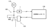
- this hydraulic switch is installed in the hydraulic circuit 100 of the automatic transmission mounted on the vehicle. That is, the hydraulic circuit 100 is equipped with a solenoid valve 120 having a characteristic of changing the operating hydraulic pressure supplied to the frictional engagement element 110 of the automatic transmission according to a change in supply current. In between, this hydraulic switch 1 is equipped.
- the hydraulic switch 1 outputs an ON signal when the hydraulic pressure is higher than a predetermined pressure, and outputs an OFF signal when the hydraulic pressure is lower than the predetermined pressure.
- a detection signal of the hydraulic switch 1 is input to the transmission controller 130, and the transmission controller 130 controls the solenoid valve 120 based on the detection signal of the hydraulic switch 1.
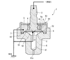
- FIG. 1 is a longitudinal sectional view of a hydraulic switch according to the present embodiment.
- the hydraulic switch 1 includes a diaphragm portion 2, a terminal portion 3 having a contact portion 31 facing the diaphragm portion 2, an insulating ring 4 surrounding the outer periphery of the terminal portion 3, and an insulating ring 4. And a conductive holder 6 that holds the conductive ring 5 and the diaphragm portion 2.
- the diaphragm portion 2, the terminal portion 3, the insulating ring 4, the conductive ring 5, and the conductive holder 6 are all substantially axisymmetric members and are disposed on the same axis. Moreover, the diaphragm part 2, the terminal part 3, the insulating ring 4, and the conductive ring 5 are attached to the conductive holder 6, and the conductive holder 6 is fixed to a valve body (not shown). And the part (upper side in FIG. 1) which protrudes from a valve body is immersed in the oil of an oil pan.
- the conductive holder 6 has an oil introduction hole 61 formed in an axial center portion on one end side in the axial direction (lower end side in FIG. 1), and a terminal on the other end side in the axial direction (upper end side in FIG. 1).
- a housing space 62 for housing the main portion of the portion 3, the insulating ring 4 and the conductive ring 5 and the diaphragm portion 2 opens to the other end side, and is recessed so as to expand in the radial direction around the axis. .
- the oil introduction hole 61 is an oil introduction space into which hydraulic oil is introduced from the opening 61 a at the tip toward the accommodation space 62.
- the opening 61a at the tip of the oil introduction hole 61 is narrower in diameter than the inside of the oil introduction hole 61, suppresses the dynamic influence of the hydraulic oil, and responds accurately to the static pressure. .
- the accommodation space 62 is a space mainly divided by a substantially cylindrical peripheral wall portion and a conical bottom portion reduced in diameter toward the oil introduction hole 61, and a peripheral wall portion near the outer periphery of the bottom portion An annular groove 63 that is recessed on one end side (lower end side) is formed between them, and a seal ring 7 is housed in the groove 63.
- annular convex portion 52 that protrudes from the one end surface 51 in one end direction (downward) is provided.
- the end face is brought into pressure contact with the seal ring 7, and one end thereof is accommodated in the accommodating space 62.
- the diaphragm portion 2 is formed in a disc shape, and its outer peripheral portion is sandwiched and fixed between the bottom surface portion of the accommodation space 62 and the annular convex portion 52 of the conductive ring 5.
- a thin claw-shaped caulking portion 64 is formed on the outer periphery of the opening of the accommodation space 62 of the conductive holder 6.
- the conductive ring 5 is fixed by being caulked by a caulking portion 64 whose end surface 53 is bent in a state where the annular convex portion 52 is crimped to the seal ring 7 with the diaphragm portion 2 interposed therebetween.
- a liquid-permeable filter 10 that covers a communication hole 9 to be described later is applied to the conductive ring 5 from the outside (upper in FIG. 1) and is jointed with the conductive ring 5 by the caulking portion 64. It is fixed by tightening.
- the filter 10 will also be described later.
- the terminal portion 3 has a front end portion (a lower end portion in FIG. 1) having a contact portion 31 coupled to the conductive ring 5 via the insulating ring 4, and the conductive ring 5 and the insulating ring 4. It is fixed to the conductive holder 6 via. Accordingly, the terminal portion 3 is also fixed to the conductive holder 6 by the conductive ring 5 being caulked and fixed to the conductive holder 6.
- a contact chamber 8 including a region between the diaphragm portion 2 and the contact portion 31 is defined between the insulating ring 4 and one end side of the terminal portion 3 (including the contact portion 31).
- the conductive ring 5 is formed with a communication hole 9 that communicates the inside of the contact chamber 8 and the outside of the contact chamber 8 (the outside of the other end side of the terminal portion 3 (upper side in FIG. 1)). Oil outside the contact chamber 8 can enter and leave the chamber 8. However, the oil introduced into the contact chamber 8 is normal pressure oil in the oil pan.
- the hydraulic pressure (detected hydraulic pressure) of the hydraulic oil introduced from the oil introduction hole 61 acts on one surface (the lower surface in FIG. 1) of the diaphragm portion 2, and the other surface (the upper surface in FIG. 1) of the diaphragm portion 2.
- the oil pressure of normal pressure oil in the oil pan acts on the contact chamber 8 side.
- the diaphragm portion 2 If the detected hydraulic pressure introduced into the oil introduction hole 61 becomes higher than the normal pressure, the diaphragm portion 2 approaches the contact portion 31, and if the detected hydraulic pressure becomes higher than a certain level with respect to the normal pressure, the diaphragm portion 2 becomes the contact portion. 31 is contacted.
- the conductive ring 5 and the diaphragm portion 2 are grounded and have a ground potential, while a constant voltage is applied to the terminal portion 3. If the diaphragm part 2 is separated from the contact part 31 of the terminal part 3, the terminal part 3 will be in a constant voltage state, but if the diaphragm part 2 contacts the contact part 31 of the terminal part 3 in response to a high detection oil pressure When energized, the voltage at the terminal unit 3 drops to the ground potential. Using this principle, the hydraulic switch 1 is turned on and off.
- the detected oil pressure introduced from the oil introduction hole 61 is less than a certain pressure, the deformation of the diaphragm portion 2 is small, and the diaphragm portion 2 is separated from the contact portion 31 of the terminal portion 3. It becomes a constant voltage state and is turned off in this state.
- the detected hydraulic pressure introduced from the oil introduction hole 61 is equal to or greater than a certain pressure, the deformation of the diaphragm portion 2 is large, and the diaphragm portion 2 contacts the contact portion 31 of the terminal portion 3, so that the terminal portion 3 is grounded. In this state, an ON signal is output. Accordingly, if a predetermined hydraulic pressure is generated, the terminal unit 3 drops to the ground potential, the hydraulic switch 1 outputs an ON signal, and if the predetermined hydraulic pressure is not generated, the terminal unit 3 maintains a constant voltage state. The hydraulic switch 1 outputs an off signal.
- the communication hole 9 is formed because oil flows between the inside of the contact chamber 8 and the outside of the contact chamber 8 according to the deformation of the diaphragm portion 2 due to the detected hydraulic pressure. This is to improve the deformation responsiveness of the diaphragm portion 2 so that the oil does not hinder the pressure deformation of the diaphragm portion 2.
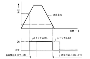
- the time chart of FIG. 3 shows the time change of the oil pressure at the top, and the on / off change of the hydraulic switch 1 corresponding to this time change at the bottom.
- the switch A indicated by the solid line indicates the characteristics of the hydraulic switch 1 having the communication hole 9
- the switch B indicated by the broken line indicates the characteristics of the hydraulic switch not having the communication hole 9.
- the oil in the contact chamber 8 prevents the diaphragm portion 2 from being pressed and deformed. There is a large delay in the response of the switch from off to on or from on to off.
- the oil in the contact chamber 8 is unlikely to obstruct the pressure deformation of the diaphragm portion 2, so that the switch is turned off in response to a change in the hydraulic pressure.
- the response delay from ON to ON or from ON to OFF is small, and by providing the communication hole 9, the responsiveness as a hydraulic switch is greatly improved.
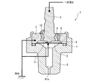
- FIG. 4 is a comparative example of the present embodiment, which includes a communication hole 9 that communicates the inside and outside of the contact chamber 8, but does not include a filter 10 that covers the communication hole 9.
- the oil flows through the communication hole 9, so that there is a high possibility that the contaminants 11 and 12 flow with the oil and bite into the opening of the communication hole 9. Since the oil in the oil pan includes conductive metal contamination, the contaminations 11 and 12 may be metallic and conductive.
- FIG. 4 illustrates a relatively small contaminant 11 and a relatively large contaminant 12.
- the small contamination 11 is shown larger than the actual size so that it can be easily discriminated.
- the relatively small contaminant 11 enters the contact chamber 8 from the communication hole 9, but the relatively large contaminant 12 does not enter the contact chamber 8 from the opening of the communication hole 9. 9 may be bitten near the opening.
- the small contamination 11 enters the inside of the contact chamber 8, it may be caught between the contact portion 31 or the like of the terminal portion 3 and the diaphragm portion 2. In this case, if the contamination is conductive, the terminal unit 3 becomes the installation potential and the hydraulic switch outputs an ON signal even if the diaphragm unit 2 is not pressed and deformed by the detected hydraulic pressure.
- the diaphragm portion 2 is prevented from being pressed and deformed by the detected oil pressure. Therefore, even if the detected oil pressure increases, the diaphragm portion 2 May not be deformed. In this case, if the contamination is not energized, the hydraulic switch 1 continues to output an off signal even if the detected hydraulic pressure increases.
- the contaminant 11 may bite so as to energize the conductive ring 5 and the terminal portion 3. In this case, even if the diaphragm portion 2 is not pressed and deformed by the detected hydraulic pressure, the terminal portion 3 becomes the installation potential and the hydraulic switch outputs an ON signal.
- a liquid-permeable and insulating filter 10 that covers an external opening (upper opening in the figure) 9a of the communication hole 9 is provided. Equipped.
- the filter 10 has a donut shape (hollow disk shape), and the terminal portion 3 is inserted into the central hole portion of the donut shape, and the vicinity of the outer periphery is caulked together with the conductive ring 5 by the caulking portion 64. It is fixed.
- the filter 10 prevents contamination from entering into the contact chamber 8 from the communication hole 9 and biting of contamination at the outside entrance of the communication hole 9, and oil flows through the inside and outside of the contact chamber 8 as a function of the communication hole 9. It is possible.
- the filter 10 is made of an insulating material and is equipped so as to cover the entire exposed surface of the conductive ring 5. Therefore, the conductive ring 5 has no portion that is directly exposed to the outside, and the outer surface side of the conductive ring 5 is insulated and coated by the filter 10. Here, the filter 10 covers the entire surface of the other end surface 53 (the upper surface in FIG. 1) of the conductive ring 5, but it is sufficient to cover at least the exposed surface of the conductive ring 5.
- the hydraulic switch 1 Since the hydraulic switch 1 is configured as described above, the following effects can be obtained. That is, by providing the filter 10 so as to cover the communication hole 9, it is possible to prevent the contamination 11 from entering the contact chamber 8 from the communication hole 9 and the contamination 12 from entering the outside entrance of the communication hole 9. . As a result, it is possible to prevent a malfunction of the hydraulic switch 1 caused by contamination.
- the filter 10 is non-liquid-permeable and does not allow liquid to pass through, it is difficult to allow oil to pass through, but the filter 10 is applied with a liquid-permeable filter that allows hydraulic oil to pass through. Therefore, oil can be circulated between the inside and outside of the contact chamber 8 without any trouble.
- the filter 10 when the filter 10 is provided only in the vicinity of the opening of the communication hole 9, the conductive ring 5 and the terminal portion 3 are connected so that the relatively large conductive contamination 12 straddles the vicinity of the opening of the communication hole 9. If it is bitten to energize, the hydraulic switch 1 may malfunction.
- the conductive ring 5 and the terminal portion 3 are insulated. Since the filter 10 is insulated, it is possible to prevent the hydraulic switch 1 from malfunctioning.
- the filter 10 it is conceivable to fix the filter 10 with an adhesive.
- the communication hole 9 is very small, and the communication hole 9 may be filled when the adhesive is applied. Since it is fixed and no adhesive is used, such problems can be avoided.
- the insulating filter 10 covers the entire exposed surface of the conductive ring 5 so as to cope with a problem caused by the large conductive contamination 12, but at least the liquid-permeable filter is communicated. Even if a small contamination 11 is only provided so as to cover the opening of the hole 9 so as to prevent the small contamination 11 from entering the communication hole 9, it is possible to cope with a problem caused by the small contamination 11.
- the communication hole 9 is provided in the conductive ring 5.
- the communication hole 9 may be any as long as it allows communication between the inside and outside of the contact chamber 8.
- the communication hole 9 may be provided in the insulating ring 4. Good.
Landscapes
- Physics & Mathematics (AREA)
- Fluid Mechanics (AREA)
- Switches Operated By Changes In Physical Conditions (AREA)
Abstract
ダイヤフラム部(2)と、ダイヤフラム部(2)と対向する接点部(31)を有するターミナル部(3)と、ターミナル部(3)の外周を囲む絶縁性リング(4)と、絶縁性リング(4)の外周を囲む導電性リング(5)と、導電性リング(5)及びダイヤフラム部(2)を把持する導電性ホルダ(6)と、ダイヤフラム部(2)と接点部(31)との間の領域に区画形成された接点室(8)と、接点室の内外を連通する連通孔(9)と、を有している。さらに、連通孔(9)の外部側開口を覆う通液性のフィルタ(10)を有している。フィルタ(10)があることで、連通孔(9)から接点室(8)側へのコンタミの侵入を抑制することができる。
Description
本発明は、油圧式自動変速機の摩擦締結要素等の油圧作動機器に供給される作動油圧を検出するのに好適な油圧スイッチに関するものである。
油圧式自動変速機には、各摩擦締結要素に供給される作動油圧を検出するために、各摩擦締結要素への油圧回路上に油圧スイッチが設けられることがある(特許文献1参照)。
この油圧スイッチは、作動油圧がある閾値よりも高ければオン信号を出力し、ある閾値よりも低ければオフ信号を出力するようなオンオフスイッチが採用され、例えば、一般的に知られているダイヤフラム式の油圧スイッチを用いることができる。
この油圧スイッチは、作動油圧がある閾値よりも高ければオン信号を出力し、ある閾値よりも低ければオフ信号を出力するようなオンオフスイッチが採用され、例えば、一般的に知られているダイヤフラム式の油圧スイッチを用いることができる。
従来のダイヤフラム式の油圧スイッチでは、ダイヤフラムとターミナルの接点とが接触可能に配置されている接点室を、接点室の外部と連通接続する連通孔が設けられており、当該連通孔を介して接点室中に油を充填している。
接点室内に作動油を充填する理由は、油圧スイッチ自体の応答性にラグを持たせるためや、ダイヤフラムの劣化を防止するためである。
接点室内に作動油を充填する理由は、油圧スイッチ自体の応答性にラグを持たせるためや、ダイヤフラムの劣化を防止するためである。
しかし、当該連通孔から導電性又は絶縁性の夾雑物(以下、コンタミという)が侵入してしまうことがある。
導電性のコンタミがダイヤフラムとターミナルの接点との間に侵入すると、ダイヤフラムとターミナルの接点とが常時接続となり、油圧スイッチの機能が阻害される。
また、絶縁性のコンタミが侵入すると、ダイヤフラムとターミナルの接点とが接触しようとする際に、当該絶縁性のコンタミが両者の間に挟まって、油圧スイッチの機能が阻害されるおそれがある。
導電性のコンタミがダイヤフラムとターミナルの接点との間に侵入すると、ダイヤフラムとターミナルの接点とが常時接続となり、油圧スイッチの機能が阻害される。
また、絶縁性のコンタミが侵入すると、ダイヤフラムとターミナルの接点とが接触しようとする際に、当該絶縁性のコンタミが両者の間に挟まって、油圧スイッチの機能が阻害されるおそれがある。
本発明は上記課題を解決するもので、接点室を外部と連通接続する連通孔が設けられたダイヤフラム式の油圧スイッチにおいて、連通孔から接点室側へのコンタミの侵入を抑制することができるようにすることを目的とする。
上記の目的を達成するために、本発明の油圧スイッチは、油圧作動機器の作動油中に設けられたダイヤフラム式の油圧スイッチであって、ダイヤフラム部と、前記ダイヤフラム部と対向する接点部を有するターミナル部と、前記ターミナル部の外周を囲む絶縁性リングと、前記絶縁性リングの外周を囲む導電性リングと、前記導電性リング及び前記ダイヤフラム部を把持する導電性ホルダと、前記ダイヤフラム部と前記接点部との間の領域に区画形成された接点室と、前記導電性リング及び前記絶縁性リングの何れかに設けられ前記接点室の内部と外部とを連通する連通孔と、前記連通孔を覆う通液性のフィルタと、を有している。
前記フィルタは、絶縁性を有すると共に、前記接点室の外部における前記導電性リングの露出表面全面を覆うことが好ましい。
前記フィルタは、ドーナツ形状を有しており、前記ドーナツ形状の中央孔部に前記ターミナル部が挿入されており、前記ドーナツ形状の外周端部が、前記導電性ホルダによりかしめ固定されていることが好ましい。
前記フィルタは、ドーナツ形状を有しており、前記ドーナツ形状の中央孔部に前記ターミナル部が挿入されており、前記ドーナツ形状の外周端部が、前記導電性ホルダによりかしめ固定されていることが好ましい。
本発明によれば、導電性リングは連通孔を有し、この連通孔を覆う通液性のフィルタを有しており、接点室内と接点室外とは、連通孔及びフィルタを介して連通しているので、連通孔を通じて接点室中に油を充填できると共に、フィルタにより接点室内へのコンタミの侵入を防止することができる。
また、フィルタが液体を通さない非通液性のフィルタであると、油を通過させることが困難となるが、本フィルタは油を通過させることができる通液性のものであるので、接点室中に油を円滑に導入することができる。
以下、図面を参照して、本発明の実施の形態について説明する。なお、以下に示す実施形態はあくまでも例示に過ぎず、以下の実施形態で明示しない種々の変形や技術の適用を排除する意図はない。以下の実施形態の構成は、それらの趣旨を逸脱しない範囲で種々変形して実施することができる。
[油圧スイッチの概要構成]
本実施形態にかかる油圧スイッチは、油圧が作用されることによりダイヤフラム部が変形し、そのダイヤフラム部の変形に伴ってオン,オフが切り換えられるダイヤフラム式の油圧スイッチであり、油圧作動機器の作動油中に臨んで配設され、作動油の油圧に応答して作動する。この例では、油圧作動機器として油圧作動式の摩擦締結要素を例示する。
本実施形態にかかる油圧スイッチは、油圧が作用されることによりダイヤフラム部が変形し、そのダイヤフラム部の変形に伴ってオン,オフが切り換えられるダイヤフラム式の油圧スイッチであり、油圧作動機器の作動油中に臨んで配設され、作動油の油圧に応答して作動する。この例では、油圧作動機器として油圧作動式の摩擦締結要素を例示する。
また、図示しないが、この油圧スイッチは、車両用の油圧式の自動変速機の底部に設けられたオイルパン内に、貯留された油(ATF:Automatic Transmission Fluid)に浸かった状態で設けられている。また、油圧スイッチは、変速を行なうための油圧を制御するバルブボディに固定されているものとする。
さらに、この油圧スイッチは、図2に示すように、車両に搭載される自動変速機の油圧回路100内に装備される。つまり、油圧回路100には、供給電流の変化に伴い自動変速機の摩擦締結要素110に供給される作動油圧を変化させる特性を有するソレノイド弁120が装備され、ソレノイド弁120と摩擦締結要素110との間に、本油圧スイッチ1が装備される。
油圧スイッチ1は、作動油圧が所定圧以上でオン信号を出力し、所定圧未満でオフ信号を出力する。この例では、油圧スイッチ1の検出信号が変速機コントローラ130に入力され、変速機コントローラ130はこの油圧スイッチ1の検出信号に基づいてソレノイド弁120を制御する。
[油圧スイッチの具体的構成]
図1は本実施形態にかかる油圧スイッチの縦断面図である。図1に示すように、油圧スイッチ1は、ダイヤフラム部2と、ダイヤフラム部2と対向する接点部31を有するターミナル部3と、ターミナル部3の外周を囲む絶縁性リング4と、絶縁性リング4の外周を囲む導電性リング5と、導電性リング5及びダイヤフラム部2を把持する導電性ホルダ6と、を有している。
図1は本実施形態にかかる油圧スイッチの縦断面図である。図1に示すように、油圧スイッチ1は、ダイヤフラム部2と、ダイヤフラム部2と対向する接点部31を有するターミナル部3と、ターミナル部3の外周を囲む絶縁性リング4と、絶縁性リング4の外周を囲む導電性リング5と、導電性リング5及びダイヤフラム部2を把持する導電性ホルダ6と、を有している。
ダイヤフラム部2、ターミナル部3、絶縁性リング4、導電性リング5及び導電性ホルダ6は、何れもほぼ軸対称の部材であり、同一の軸心上に配置されている。また、ダイヤフラム部2、ターミナル部3、絶縁性リング4及び導電性リング5は、導電性ホルダ6に取り付けられ、導電性ホルダ6が図示しないバルブボディに固定される。そして、バルブボディから突出する部分(図1中の上部側)がオイルパンの油中に浸漬されている。
導電性ホルダ6は、軸方向の一端側(図1中では下端側)の軸心部分に、油導入穴61が形成され、軸方向の他端側(図1中では上端側)に、ターミナル部3、絶縁性リング4及び導電性リング5の主要部とダイヤフラム部2とを収容する収容空間62が、他端側に開口し、軸心を中心に径方向に広がって凹設されている。
油導入穴61は、先端の開口61aから収容空間62に向けて作動油が導入される油導入空間である。油導入穴61の先端の開口61aは油導入穴61の内部よりも径が狭められており、作動油の動的な影響を抑制し、静圧に対して精度よく反応するようになっている。
収容空間62は、ほぼ円筒状の周壁部と、油導入穴61の側に向かって縮径した円錐状の底面部とで主に区画された空間であり、底面部の外周寄りの周壁部との間には、一端側(下端側)に窪んだ円環状の溝63が形成されて、この溝63内には、シールリング7が内装される。
導電性リング5の外周部の一端側(下端側)には、一端面51から一端方向(下方)に突設された環状凸部52が設けられ、導電性リング5はこの環状凸部52の端面をシールリング7に圧接させて、その一端側を収容空間62内に収容される。ダイヤフラム部2は、円板状に形成され、その外周部分を収容空間62の底面部と導電性リング5の環状凸部52とで挟まれて固定されている。
導電性ホルダ6の収容空間62の開口外周には、薄肉の爪状のかしめ部64が形成されている。導電性リング5は、ダイヤフラム部2を挟んで環状凸部52を、シールリング7に圧着した状態で、他端面53を折り曲げられたかしめ部64によってかしめられて固定される。
ただし、本油圧スイッチ1では、後述する連通孔9を覆う通液性のフィルタ10が導電性リング5に外方(図1中上方)から当てがわれてかしめ部64によって導電性リング5と共締めで固定されている。フィルタ10についても後述する。
ターミナル部3は、接点部31を有する先端部(図1中で下側の端部)が絶縁性リング4を介して導電性リング5に結合されており、導電性リング5及び絶縁性リング4を介して導電性ホルダ6に固定される。したがって、導電性リング5が導電性ホルダ6にかしめられて固定されることで、ターミナル部3も導電性ホルダ6に固定される。
このように、導電性リング5、絶縁性リング4及びターミナル部3が固定された導電性ホルダ6の収容空間62内において、ダイヤフラム部2の他端面(図1中で上面)と、導電性リング5、絶縁性リング4及びターミナル部3の一端側(接点部31を含む)との間には、ダイヤフラム部2と接点部31との間の領域を含んだ接点室8が区画形成されている。
また、導電性リング5には、接点室8の内部と接点室8の外部(ターミナル部3の他端側(図1中の上側)の外部)とを連通する連通孔9が形成され、接点室8の内部に接点室8の外部の油が入出できるようになっている。ただし、接点室8の内部に導入される油は、オイルパン内の常圧の油である。
したがって、ダイヤフラム部2の一面(図1中の下面)には、油導入穴61から導入された作動油の油圧(検出油圧)が作用し、ダイヤフラム部2の他面(図1中の上面)の接点室8側には、オイルパン内の常圧の油の油圧が作用する。
油導入穴61に導入された検出油圧が常圧よりも高くなれば、ダイヤフラム部2は接点部31に接近し、検出油圧が常圧に対して一定以上高くなれば、ダイヤフラム部2は接点部31と接触する。
導電性リング5及びダイヤフラム部2は接地され接地電位となっていて、一方、ターミナル部3には一定電圧が印加されている。ダイヤフラム部2がターミナル部3の接点部31から離隔していれば、ターミナル部3は一定電圧状態となるが、高い検出油圧を受けてダイヤフラム部2がターミナル部3の接点部31に接触すれば通電して、ターミナル部3の電圧は接地電位に降下する。この原理を用いて、本油圧スイッチ1はオンオフ動作する。
つまり、油導入穴61から導入された検出油圧が一定圧未満であれば、ダイヤフラム部2の変形は小さく、ダイヤフラム部2はターミナル部3の接点部31から離隔しているため、ターミナル部3は一定電圧状態となり、この状態ではオフとする。
一方、油導入穴61から導入された検出油圧が一定圧以上であれば、ダイヤフラム部2の変形は大きく、ダイヤフラム部2はターミナル部3の接点部31に接触するため、ターミナル部3は接地電位に降下し、この状態ではオン信号を出力する。
したがって、所定の油圧が発生すれば、ターミナル部3は接地電位に降下し、本油圧スイッチ1はオン信号を出力し、所定の油圧が発生しなければ、ターミナル部3は一定電圧状態を維持し、本油圧スイッチ1はオフ信号を出力する。
したがって、所定の油圧が発生すれば、ターミナル部3は接地電位に降下し、本油圧スイッチ1はオン信号を出力し、所定の油圧が発生しなければ、ターミナル部3は一定電圧状態を維持し、本油圧スイッチ1はオフ信号を出力する。
ここで、連通孔9について説明する。
連通孔9を形成しているのは、ダイヤフラム部2の検出油圧による変形に応じて、接点室8の内部と接点室8の外部との間で油が流通することで、接点室8内の油がダイヤフラム部2の押圧変形の妨げにならないようにして、ダイヤフラム部2の変形応答性を向上させるためである。
連通孔9を形成しているのは、ダイヤフラム部2の検出油圧による変形に応じて、接点室8の内部と接点室8の外部との間で油が流通することで、接点室8内の油がダイヤフラム部2の押圧変形の妨げにならないようにして、ダイヤフラム部2の変形応答性を向上させるためである。
図3のタイムチャートは、上部に油圧の時間変化を示し、下部にこの時間変化に対応した油圧スイッチ1のオンオフ変化を示す。下部のグラフのうち、実線で示すスイッチAは連通孔9を有する本油圧スイッチ1の特性を示し、破線で示すスイッチBは連通孔9を有さない油圧スイッチの特性を示す。
図3に示すように、破線で示す連通孔9を有さないスイッチBは、接点室8内の油がダイヤフラム部2の押圧変形の妨げになるため、油圧の上昇あるいは下降といった変化に対してスイッチのオフからオンあるいはオンからオフへの応答に大きな遅れが生じる。
これに対して、実線で示す連通孔9を有するスイッチAは、接点室8内の油がダイヤフラム部2の押圧変形の妨げになりにくいため、油圧の上昇あるいは下降といった変化に対してスイッチのオフからオンあるいはオンからオフへの応答遅れが小さく、連通孔9を設けることで油圧スイッチとしての応答性が大きく改善される。
連通孔9はこのような効果を奏する反面、連通孔9により新たな課題も発生する。図4は本実施形態の比較例であり、接点室8の内外を連通する連通孔9は備えているが連通孔9を覆うフィルタ10は備えていない。
連通孔9を設けると、連通孔9内を油が流通するため、コンタミ11,12が油とともに流動して連通孔9の開口部等に噛み込むおそれが高まる。オイルパン内の油には通電性の金属コンタミも含まれるため、コンタミ11,12が金属で導電性がある場合もある。
図4には、比較的小さなコンタミ11と比較的大きなコンタミ12とを例示する。ただし、小さなコンタミ11については、判別しやすいように実際よりも大きく記載している。この比較的小さなコンタミ11は、連通孔9から接点室8の内部に侵入するが、比較的大きなコンタミ12は連通孔9の開口部から接点室8の内部に侵入することはないものの、連通孔9の開口部付近に噛み込むことがある。
また、小さなコンタミ11が、接点室8の内部に侵入すると、ターミナル部3の接点部31等とダイヤフラム部2との間に噛み込むことがある。この場合、コンタミが通電性ならダイヤフラム部2が検出油圧によって押圧変形しなくてもターミナル部3は設置電位となって油圧スイッチはオン信号を出力する。
また、ターミナル部3の接点部31等とダイヤフラム部2との間にコンタミが噛み込むと、ダイヤフラム部2が検出油圧によって押圧変形するのを妨げるため、検出油圧が高くなっても、ダイヤフラム部2が変形しないことがある。この場合、コンタミが非通電性なら検出油圧が高くなっても油圧スイッチ1はオフ信号を出力し続けてしまう。
一方、大きなコンタミ12が通電性であると、コンタミ11が導電性リング5とターミナル部3とを通電するように噛み込むことがある。この場合、ダイヤフラム部2が検出油圧によって押圧変形しなくてもターミナル部3は設置電位となって油圧スイッチはオン信号を出力する。
こうした不具合を解消するために、本油圧スイッチ1では、図1に示すように、連通孔9の外部側開口(図中、上側の開口)9aを覆う通液性で且つ絶縁性のフィルタ10を装備している。フィルタ10は、ドーナツ形状(中空円板状)をしており、ドーナツ形状の中央孔部にターミナル部3が挿入されて、外周近傍をかしめ部64によって導電性リング5と共締めでかしめられて固定されている。
フィルタ10は、連通孔9から接点室8内へのコンタミの侵入や、連通孔9の外側入り口におけるコンタミの噛み込みを防止するとともに、連通孔9の機能として接点室8の内外を油が流通可能となっている。
また、フィルタ10は絶縁性の材料で構成され、導電性リング5の露出表面全面を覆うように装備されている。したがって、導電性リング5は外部に直接露出する部分がなくなり、導電性リング5の外面側はフィルタ10により絶縁被覆される。ここでは、フィルタ10が導電性リング5の他端面53(図1の上面)の全面を覆っているが、少なくとも導電性リング5の露出する表面について全面を覆えばよい。
[作用及び効果]
本油圧スイッチ1は、このように構成されているため、以下のような効果を奏する。
つまり、連通孔9を覆うようにフィルタ10を設けることによって、連通孔9から接点室8内へのコンタミ11の侵入や、連通孔9の外側入り口におけるコンタミ12の噛み込みを防止することができる。これによって、コンタミの噛み込みに起因した油圧スイッチ1の作動不良の発生を防止することができる。
本油圧スイッチ1は、このように構成されているため、以下のような効果を奏する。
つまり、連通孔9を覆うようにフィルタ10を設けることによって、連通孔9から接点室8内へのコンタミ11の侵入や、連通孔9の外側入り口におけるコンタミ12の噛み込みを防止することができる。これによって、コンタミの噛み込みに起因した油圧スイッチ1の作動不良の発生を防止することができる。
また、フィルタ10が液体を通さない非通液性のものであると、油を通過させることが困難となるが、本フィルタ10は、作動油を通過させることができる通液性のフィルタが適用されているので、接点室8内部と外部との間での油の流通を支障なく行うことができる。
さらに、連通孔9の開口部付近のみにフィルタ10を装備した場合、比較的大きな導電性のコンタミ12が連通孔9の開口部付近を跨ぐようにして、導電性リング5とターミナル部3とを通電するように噛み込むと、油圧スイッチ1の作動不良を招くことがある。この点、導電性リング5の露出表面全面を絶縁性のフィルタ10で覆っているので、大きな導電性のコンタミ12が流れてきても、導電性リング5とターミナル部3との間が絶縁性のフィルタ10で絶縁されているため、油圧スイッチ1の作動不良の発生を防止することができる。
加えて、フィルタ10を接着剤で固定することが考えられるが、連通孔9は非常に小さく、接着剤塗布するときに連通孔9が埋められてしまうおそれがあるが、導電性ホルダ6にかしめ固定して接着剤を用いていないので、こうした不具合も回避することができる。
[その他]
以上、本発明の実施形態を説明したが、本発明は、これらの実施形態に限定されず、本発明の趣旨を逸脱しない範囲で種々変形して実施することができる。
以上、本発明の実施形態を説明したが、本発明は、これらの実施形態に限定されず、本発明の趣旨を逸脱しない範囲で種々変形して実施することができる。
例えば、上記実施形態では、絶縁性のフィルタ10が導電性リング5の露出表面全面を覆って、大きな導電性のコンタミ12による不具合にも対処できるようにしたが、少なくとも通液性のフィルタを連通孔9の開口部を覆うように部分的に設けて、小さなコンタミ11の連通孔9内への侵入を防止するようにするだけでも、小さなコンタミ11による不具合には対処できる。
また、上記実施形態では導電性リング5に連通孔9を設けたが、連通孔9は接点室8の内外を連通させるものであればよく、例えば絶縁性リング4に連通孔9を設けてもよい。
また、上記実施形態では導電性リング5に連通孔9を設けたが、連通孔9は接点室8の内外を連通させるものであればよく、例えば絶縁性リング4に連通孔9を設けてもよい。
Claims (3)
- 油圧作動機器の作動油中に設けられたダイヤフラム式の油圧スイッチであって、
ダイヤフラム部と、
前記ダイヤフラム部と対向する接点部を有するターミナル部と、
前記ターミナル部の外周を囲む絶縁性リングと、
前記絶縁性リングの外周を囲む導電性リングと、
前記導電性リング及び前記ダイヤフラム部を把持する導電性ホルダと、
前記ダイヤフラム部と前記接点部との間の領域に区画形成された接点室と、
前記導電性リング及び前記絶縁性リングの何れかに設けられ前記接点室の内部と外部とを連通する連通孔と、
前記連通孔を覆う通液性のフィルタと、
を有している油圧スイッチ。 - 請求項1に記載の油圧スイッチにおいて、
前記フィルタは、絶縁性を有すると共に、前記接点室の外部における前記導電性リングの露出表面全面を覆うものである油圧スイッチ。 - 請求項2に記載の油圧スイッチにおいて、
前記フィルタは、ドーナツ形状を有しており、
前記ドーナツ形状の中央孔部に前記ターミナル部が挿入されており、
前記ドーナツ形状の外周端部が、前記導電性ホルダによりかしめ固定されている油圧スイッチ。
Priority Applications (1)
| Application Number | Priority Date | Filing Date | Title |
|---|---|---|---|
| JP2020505620A JP7030182B2 (ja) | 2018-03-16 | 2019-01-17 | 油圧スイッチ |
Applications Claiming Priority (2)
| Application Number | Priority Date | Filing Date | Title |
|---|---|---|---|
| JP2018-049987 | 2018-03-16 | ||
| JP2018049987 | 2018-03-16 |
Publications (1)
| Publication Number | Publication Date |
|---|---|
| WO2019176271A1 true WO2019176271A1 (ja) | 2019-09-19 |
Family
ID=67907570
Family Applications (1)
| Application Number | Title | Priority Date | Filing Date |
|---|---|---|---|
| PCT/JP2019/001178 Ceased WO2019176271A1 (ja) | 2018-03-16 | 2019-01-17 | 油圧スイッチ |
Country Status (2)
| Country | Link |
|---|---|
| JP (1) | JP7030182B2 (ja) |
| WO (1) | WO2019176271A1 (ja) |
Citations (4)
| Publication number | Priority date | Publication date | Assignee | Title |
|---|---|---|---|---|
| JPS61119223U (ja) * | 1985-01-10 | 1986-07-28 | ||
| JPH0935601A (ja) * | 1995-07-20 | 1997-02-07 | Toyoda Mach Works Ltd | 圧力スイッチ |
| JP2015220210A (ja) * | 2014-05-21 | 2015-12-07 | トヨタ自動車株式会社 | 油圧スイッチ |
| WO2018016478A1 (ja) * | 2016-07-20 | 2018-01-25 | リューベ株式会社 | 流体の流動検知装置 |
-
2019
- 2019-01-17 JP JP2020505620A patent/JP7030182B2/ja active Active
- 2019-01-17 WO PCT/JP2019/001178 patent/WO2019176271A1/ja not_active Ceased
Patent Citations (4)
| Publication number | Priority date | Publication date | Assignee | Title |
|---|---|---|---|---|
| JPS61119223U (ja) * | 1985-01-10 | 1986-07-28 | ||
| JPH0935601A (ja) * | 1995-07-20 | 1997-02-07 | Toyoda Mach Works Ltd | 圧力スイッチ |
| JP2015220210A (ja) * | 2014-05-21 | 2015-12-07 | トヨタ自動車株式会社 | 油圧スイッチ |
| WO2018016478A1 (ja) * | 2016-07-20 | 2018-01-25 | リューベ株式会社 | 流体の流動検知装置 |
Also Published As
| Publication number | Publication date |
|---|---|
| JPWO2019176271A1 (ja) | 2021-02-12 |
| JP7030182B2 (ja) | 2022-03-04 |
Similar Documents
| Publication | Publication Date | Title |
|---|---|---|
| EP1096141B1 (en) | Glow Plug having a combustion pressure sensor | |
| JP4052263B2 (ja) | 圧力センサ | |
| JP2018156896A (ja) | 端子及びコネクタ | |
| CN106533415A (zh) | 静电电容检测式压力开关及压力传感器 | |
| EP3712585B1 (en) | Pressure sensor | |
| KR830008081A (ko) | 바이패스 밸브(Bypass Valve) 및 경보(alarm)조립체 | |
| CN112113700B (zh) | 压力传感器装置 | |
| JP2005233781A (ja) | 温度センサ | |
| WO2019176271A1 (ja) | 油圧スイッチ | |
| JP4886006B2 (ja) | ガスセンサユニット | |
| JP2006506655A (ja) | 圧力センサモジュール | |
| JPH0445062B2 (ja) | ||
| US20200243287A1 (en) | Pressure Switch | |
| JP2009503454A (ja) | センサアセンブリ | |
| US4638132A (en) | Electrical pressure switch | |
| JP5411077B2 (ja) | コネクタ装置 | |
| JPH1130201A (ja) | ピストン型アキュムレータのピストン位置検出装置 | |
| US12050144B2 (en) | Sensor arrangement for measuring the pressure and temperature of refrigerant a fluid | |
| JP5542638B2 (ja) | 圧力検出器 | |
| JP6563845B2 (ja) | センサ | |
| EP1321956A2 (en) | Pressure switch with annular electrodes and method of making same | |
| CN105659349B (zh) | 流体关联功能装置 | |
| CN106952778B (zh) | 液压开关 | |
| JP2019207134A (ja) | ガスセンサ | |
| JP5214665B2 (ja) | ガスセンサ |
Legal Events
| Date | Code | Title | Description |
|---|---|---|---|
| 121 | Ep: the epo has been informed by wipo that ep was designated in this application |
Ref document number: 19767597 Country of ref document: EP Kind code of ref document: A1 |
|
| WWE | Wipo information: entry into national phase |
Ref document number: 2020505620 Country of ref document: JP |
|
| NENP | Non-entry into the national phase |
Ref country code: DE |
|
| 122 | Ep: pct application non-entry in european phase |
Ref document number: 19767597 Country of ref document: EP Kind code of ref document: A1 |