WO2019176221A1 - Wire harness protector and wire harness routing structure using same - Google Patents
Wire harness protector and wire harness routing structure using same Download PDFInfo
- Publication number
- WO2019176221A1 WO2019176221A1 PCT/JP2018/047233 JP2018047233W WO2019176221A1 WO 2019176221 A1 WO2019176221 A1 WO 2019176221A1 JP 2018047233 W JP2018047233 W JP 2018047233W WO 2019176221 A1 WO2019176221 A1 WO 2019176221A1
- Authority
- WO
- WIPO (PCT)
- Prior art keywords
- branch
- wire
- wire insertion
- wire harness
- portions
- Prior art date
Links
Images

Classifications
-
- B—PERFORMING OPERATIONS; TRANSPORTING
- B60—VEHICLES IN GENERAL
- B60R—VEHICLES, VEHICLE FITTINGS, OR VEHICLE PARTS, NOT OTHERWISE PROVIDED FOR
- B60R16/00—Electric or fluid circuits specially adapted for vehicles and not otherwise provided for; Arrangement of elements of electric or fluid circuits specially adapted for vehicles and not otherwise provided for
- B60R16/02—Electric or fluid circuits specially adapted for vehicles and not otherwise provided for; Arrangement of elements of electric or fluid circuits specially adapted for vehicles and not otherwise provided for electric constitutive elements
- B60R16/0207—Wire harnesses
- B60R16/0215—Protecting, fastening and routing means therefor
-
- F—MECHANICAL ENGINEERING; LIGHTING; HEATING; WEAPONS; BLASTING
- F16—ENGINEERING ELEMENTS AND UNITS; GENERAL MEASURES FOR PRODUCING AND MAINTAINING EFFECTIVE FUNCTIONING OF MACHINES OR INSTALLATIONS; THERMAL INSULATION IN GENERAL
- F16L—PIPES; JOINTS OR FITTINGS FOR PIPES; SUPPORTS FOR PIPES, CABLES OR PROTECTIVE TUBING; MEANS FOR THERMAL INSULATION IN GENERAL
- F16L3/00—Supports for pipes, cables or protective tubing, e.g. hangers, holders, clamps, cleats, clips, brackets
- F16L3/08—Supports for pipes, cables or protective tubing, e.g. hangers, holders, clamps, cleats, clips, brackets substantially surrounding the pipe, cable or protective tubing
- F16L3/12—Supports for pipes, cables or protective tubing, e.g. hangers, holders, clamps, cleats, clips, brackets substantially surrounding the pipe, cable or protective tubing comprising a member substantially surrounding the pipe, cable or protective tubing
- F16L3/123—Supports for pipes, cables or protective tubing, e.g. hangers, holders, clamps, cleats, clips, brackets substantially surrounding the pipe, cable or protective tubing comprising a member substantially surrounding the pipe, cable or protective tubing and extending along the attachment surface
-
- F—MECHANICAL ENGINEERING; LIGHTING; HEATING; WEAPONS; BLASTING
- F16—ENGINEERING ELEMENTS AND UNITS; GENERAL MEASURES FOR PRODUCING AND MAINTAINING EFFECTIVE FUNCTIONING OF MACHINES OR INSTALLATIONS; THERMAL INSULATION IN GENERAL
- F16L—PIPES; JOINTS OR FITTINGS FOR PIPES; SUPPORTS FOR PIPES, CABLES OR PROTECTIVE TUBING; MEANS FOR THERMAL INSULATION IN GENERAL
- F16L57/00—Protection of pipes or objects of similar shape against external or internal damage or wear
-
- H—ELECTRICITY
- H02—GENERATION; CONVERSION OR DISTRIBUTION OF ELECTRIC POWER
- H02G—INSTALLATION OF ELECTRIC CABLES OR LINES, OR OF COMBINED OPTICAL AND ELECTRIC CABLES OR LINES
- H02G3/00—Installations of electric cables or lines or protective tubing therefor in or on buildings, equivalent structures or vehicles
- H02G3/02—Details
- H02G3/04—Protective tubing or conduits, e.g. cable ladders or cable troughs
- H02G3/0437—Channels
-
- H—ELECTRICITY
- H02—GENERATION; CONVERSION OR DISTRIBUTION OF ELECTRIC POWER
- H02G—INSTALLATION OF ELECTRIC CABLES OR LINES, OR OF COMBINED OPTICAL AND ELECTRIC CABLES OR LINES
- H02G3/00—Installations of electric cables or lines or protective tubing therefor in or on buildings, equivalent structures or vehicles
- H02G3/02—Details
- H02G3/04—Protective tubing or conduits, e.g. cable ladders or cable troughs
- H02G3/0406—Details thereof
- H02G3/0418—Covers or lids; Their fastenings
-
- H—ELECTRICITY
- H02—GENERATION; CONVERSION OR DISTRIBUTION OF ELECTRIC POWER
- H02G—INSTALLATION OF ELECTRIC CABLES OR LINES, OR OF COMBINED OPTICAL AND ELECTRIC CABLES OR LINES
- H02G3/00—Installations of electric cables or lines or protective tubing therefor in or on buildings, equivalent structures or vehicles
- H02G3/30—Installations of cables or lines on walls, floors or ceilings
- H02G3/32—Installations of cables or lines on walls, floors or ceilings using mounting clamps
Definitions
- the present invention relates to a wire harness protector for inserting and holding a large number of electric wires routed in an automobile or the like, and a wire harness routing structure using the protector.
- such a wire harness protector includes, as described in Japanese Utility Model Publication No. 6-70415 (Patent Document 1) and the like, a bowl-shaped protector body, a lid body that covers the upper opening of the protector body, It is comprised including. And after inserting a large number of wires into the protector body, the cover body is fixed to the protector body via a locking mechanism that protrudes outward from the side wall of the protector body, so that the many wires are held in the housed state. It can be done.
- the present invention has been made in the background of the above-mentioned circumstances, and the solution is to insert and hold the wire harness including the branch portion in a compact state while suppressing the protruding height from the fixed object.
- An object of the present invention is to provide a wire harness protector having a novel structure, and to provide a wiring harness wiring structure using the protector.
- the present invention relating to a protector for a wire harness has a plurality of wire insertion portions in which a plurality of wires constituting the wire harness are subdivided and accommodated, and the plurality of wire insertion portions are arranged in parallel, At least one side in the parallel direction of the wire insertion portion is a branch direction of the wire, and each of the wire insertion portions excluding the wire insertion portion farthest from the branch direction has a longitudinal direction orthogonal to the parallel direction.
- a branch wire insertion window that extends in the longitudinal direction and opens on both side surfaces and into which a branch wire constituted by a part of the wire can be inserted is provided in the middle portion, and is furthest from the branch direction.
- the above-described branch wire insertion window is provided at least on the side surface on the branch direction side.
- the present invention relating to a wiring harness wiring structure is a wiring harness wiring structure using a wire harness protector, wherein the wire harness protector includes the wire according to any one of the first to third aspects.
- the harness protector uses the harness protector, the plurality of electric wires constituting the wire harness are subdivided and held in the plurality of electric wire insertion portions, while the electric wire insertion portion distal to the branch direction has the branch direction.
- the branch wire is pulled out to the side by passing through the branch wire insertion window on the side, while in the other wire insertion portion, adjacent to the branch wire insertion window on the branch direction side and the branch direction side
- the branched electric wires are drawn out sideways through the branched electric wire insertion windows on both side surfaces of the arranged electric wire insertion portion.
- the height of the protector for the wire harness can be reduced. Further, the wire harness including the branch portion can be inserted and held in a compact state. Moreover, it is possible to advantageously realize a reduction in the height of the wire harness protector including the branching portion.
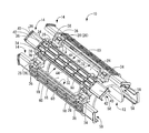
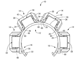
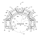
- the front view of FIG. The perspective view which shows the base member of FIG.
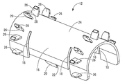
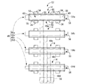
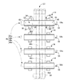
- the perspective view which shows one insertion part structural member of FIG. The top view which shows the state before the attachment to a base member which accommodated the electric wire in the some insertion part structural member, and provided the branch electric wire.
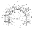
- FIG. 8 It is a top view which shows the state before the attachment to a base member in case a branch direction is both directions, Comprising: The figure corresponded in FIG. It is a front view which shows the wiring structure of the wire harness in case the branch direction shown in FIG. 8 is both directions, Comprising: The figure equivalent to FIG. The perspective view which shows the insertion part structural member of a structure different from FIG. It is a front view which shows the wiring structure of the wire harness using the protector for wire harnesses which has the insertion part structural member shown in FIG. 10, Comprising: The figure equivalent to FIG.
- the protector for wire harnesses has a some electric wire penetration part in which the some electric wire which comprises a wire harness is divided and accommodated, and the said some electric wire penetration part is arrange
- at least one side of the plurality of electric wire insertion portions in the parallel direction is a branch direction of the electric wires, and each of the electric wire insertion portions excluding the electric wire insertion portion farthest from the branch direction has the parallel direction.
- a branch wire insertion window that extends in the longitudinal direction and opens on both side surfaces and into which a branch wire constituted by a part of the wire can be inserted is provided, In the wire insertion portion farthest from the branch direction, the branch wire insertion window is provided at least on the side surface on the branch direction side.
- the plurality of electric wire insertion portions that are accommodated by dividing the plurality of electric wires are arranged in parallel, even when the number of electric wires constituting the wire harness increases, the electric wires are divided into the plurality of electric wire insertion portions. Therefore, the height of the protector for the wire harness can be reduced.
- at least one side in the parallel direction of the plurality of wire insertion portions is a branching direction of the wires, and each wire insertion portion excluding the most distal wire insertion portion from the branching direction has a longitudinal direction in the middle portion of the longitudinal direction.
- Branching wire insertion windows that open to both sides and have a branching wire insertion window that is at the most distal from the branching direction and has at least a branching wire insertion window on the side surface on the branching direction side.
- the branch wire can be pulled out to the side by inserting the branch wire insertion window on the branch direction side in the wire insertion portion farthest in the branch direction.
- the branch wire insertion windows on both sides of the branch wire insertion window on the branch direction side and the wire insertion part arranged adjacent to the branch direction side are inserted and the branch wires are pulled out to the side. Can do.
- the wire harness protector without providing an additional part for inserting and holding the branching portion in the wire harness protector, it is possible to realize stable holding of the branching wire by inserting and holding the branching wire across the plurality of wire inserting portions.
- the containing wire harness can be inserted and held in a compact state.
- each wire insertion portion is provided extending in the longitudinal direction, the position where the wire is branched for each wire insertion portion can be varied in the longitudinal direction.
- each of the electric wire insertion portions has the branch electric wire insertion windows on both side surfaces.
- the both sides of the plurality of electric wire insertion portions in the parallel direction can be the branch direction of the electric wires.
- each of the electric wire insertion portions is provided with the branched electric wire insertion windows on both side surfaces so that both sides in the parallel direction of the plurality of electric wire insertion portions are in the branching direction.
- a base member fixed to an object to be fixed and a gap on the base member are separated.
- An insertion portion configured to include a longitudinal upper wall portion opposed to each other and a pair of support legs projecting from both side edge portions of both side portions in the longitudinal direction of the upper wall portion toward the base member.
- a plurality of constituent members, and the pair of supporting leg portions of each of the insertion portion constituent members are detachably fixed to a plurality of fixing portions provided on the base member, respectively,
- the electric wire insertion portion is configured, and the branch electric wire insertion window is defined on the side surface of each electric wire insertion portion by the base member, the upper wall portion, and the support leg portions on both sides in the longitudinal direction. It is intended.
- each wire insertion portion can be configured by detachably attaching the insertion portion constituting member to the base member fixed to the fixed object on the vehicle side. Therefore, by arranging multiple wires on the base member in order from the wire insertion part on the side away from the branching direction, it is possible to improve workability and to easily and stably route the branching part. Can be.
- the insertion portion constituting member is constituted by the upper wall portion and a pair of supporting leg portions that protrude toward the base member at both side portions thereof, the electric wire that is inserted and arranged in each electric wire insertion portion is projected upward. Is suppressed. Therefore, the height of the wire harness protector can be more reliably reduced.
- a first aspect of the present invention relating to a wiring harness wiring structure is a wiring harness wiring structure using a wire harness protector, wherein the wire harness protector includes any one of the first to third elements.
- the wire harness protector according to the aspect is used, and the plurality of electric wires constituting the wire harness are subdivided and inserted and held in the plurality of electric wire insertion portions, while the electric wire insertion portion farthest in the branch direction In the branch direction side, the branch wire is pulled out to the side through the branch wire insertion window, while in the other wire insertion portion, the branch wire insertion window on the branch direction side and the branch
- the branched electric wires are drawn out sideways through the branched electric wire insertion windows on both side surfaces of the electric wire insertion portion arranged adjacent to the branch direction side.
- the wire harness protector according to the first to third aspects is used, and a plurality of electric wire insertion portions for accommodating a plurality of electric wires divided and accommodated are arranged in parallel. Therefore, even when the number of electric wires constituting the wire harness increases, the electric wires can be accommodated and held in a plurality of electric wire insertion portions, so that the height of the wire harness protector can be reduced.
- at least one side in the parallel direction of the plurality of wire insertion portions is a branching direction of the wires, and each wire insertion portion excluding the most distal wire insertion portion from the branching direction has a longitudinal direction in the middle portion of the longitudinal direction.
- Branching wire insertion windows that open to both sides and have a branching wire insertion window that is at the most distal from the branching direction and has at least a branching wire insertion window on the side surface on the branching direction side.
- the branch wire can be pulled out to the side by inserting the branch wire insertion window on the branch direction side in the wire insertion portion farthest in the branch direction.
- the branch wire insertion windows on both sides of the branch wire insertion window on the branch direction side and the wire insertion part arranged adjacent to the branch direction side are inserted and the branch wires are pulled out to the side. Can do.
- the wire harness protector without providing an additional part for inserting and holding the branching portion in the wire harness protector, it is possible to realize stable holding of the branching wire by inserting and holding the branching wire across the plurality of wire inserting portions.
- the containing wire harness can be inserted and held in a compact state.
- each wire insertion portion is provided extending in the longitudinal direction, the position where the wire is branched for each wire insertion portion can be varied in the longitudinal direction.
- the second aspect of the present invention related to the wiring structure of the wire harness is the wiring structure of the wire harness described in the first aspect, wherein the branch wire pull-out position in the plurality of wire insertion portions is the longitudinal direction. Are different from each other.
- the lead-out positions of the branch wires in the plurality of wire insertion portions are different from each other in the longitudinal direction. Therefore, since it is prevented advantageously that the electric wire branched from each electric wire insertion part overlaps, the height of the branched electric wire can be made still lower.
- the subdivided wire harness that passes through each of the electric wire insertion portions is provided in the wiring structure of the wire harness described in the first or second aspect.
- the cross-sectional area is gradually increased toward the branch direction.
- the cross-sectional area of the wire harness that passes through the wire insertion portion is gradually increased in the branching direction. That is, the electric wire inserted and arranged in the electric wire insertion portion is thinnest in the electric wire insertion portion closest to the branching direction and gradually becomes thicker toward the farthest electric wire insertion portion. Thereby, the branched electric wire does not get over the electric wire thicker than itself, the cross-sectional area of the wire harness that passes through each electric wire insertion portion can be leveled, and the low profile can be realized advantageously.
- the wire harness protector 10 includes a base member 12 and a plurality (four in the present embodiment) of insertion portion constituting members 14.
- “upper” means the upper side in FIGS. 1 to 4 and “lower” means the lower side in FIGS. 1 to 4
- “front” means the lower right side in FIG. 1 refers to the upper left diagonal direction
- the longitudinal direction refers to the front-rear direction in FIG.
- the base member 12 has a substantially inverted U-shaped cross section and has a substantially bowl shape that opens downward and extends in the longitudinal direction.
- PP polypropylene
- PA polyamide
- fixed pieces 16 are formed at both sides in the width direction (left and right direction in FIG. 2) in the center portion in the longitudinal direction of the base member 12.
- the fixing piece 16 has a cantilever shape in which both sides in the longitudinal direction are separated from the base member 12 by the notches 18 so that only the base end side is connected to the base member 12 and protrudes downward.
- a substantially rectangular flat plate-like engaging portion 20 that protrudes obliquely inwardly downward is provided at the longitudinal central portion of the protruding end portion of the fixed piece 16.
- An engaging projection 22 is formed which protrudes inward and extends in a substantially trapezoidal cross-sectional shape over substantially the entire length in the longitudinal direction.
- a plurality of pairs (four pairs in this embodiment) of fixing portions 26 and 26 are spaced apart from each other in the circumferential direction of the outer peripheral surface 24 and the outer peripheral surface. It protrudes outward so as to stand upright with respect to 24.
- the fixing portions 26 and 26 are formed so as to be spaced apart from each other in the circumferential direction of the outer peripheral surface 24 and have a substantially rectangular flat plate shape.
- Engaging protrusions 28 are provided that protrude in the longitudinal direction and extend in the longitudinal direction with a substantially triangular cross-sectional shape.
- the protruding end surface of the engagement protrusion 28 is a tapered surface that approaches the fixed portion 26 as the distance from the outer peripheral surface 24 increases.
- the insertion portion constituting member 14 has a substantially inverted U-shaped cross-sectional shape and has a substantially bowl shape that opens downward and extends in the longitudinal direction.
- PP polypropylene
- PA polyamide
- the insertion portion constituting member 14 includes an upper wall portion 30 that extends in a strip shape in the longitudinal direction, and a side wall portion that extends downward from both side edges in the width direction of the upper wall portion 30 over substantially the entire length in the longitudinal direction.
- the support leg portion 34 has a substantially frame shape with a base end portion connected to the side wall portion 32, and the upper end edge portion of the engagement hole 36 that opens in the vertical direction faces obliquely upward and inward.
- An engaging projection 38 having a substantially rectangular flat plate shape is provided.
- the insertion portion constituting member 14 has a binding fixing portion 40 that extends further outward from both longitudinal portions of the upper wall portion 30 provided with the pair of support leg portions 34, 34.
- a bundling member retaining protrusion 42 is formed on the extending end of the bundling fixing portion 40 so as to project over substantially the entire length in the width direction.
- the upper wall portion 30 is thick between the portions where the support leg portions 34 are provided, and is formed with a hollow hole 44 that opens upward in a substantially rectangular shape in plan view.
- the synthetic resin material is advantageously saved while increasing the strength of the portion where the portion 34 is provided.
- the wire harness 46 includes wire harnesses 46a to 46d composed of a plurality of subdivided electric wires.
- the wire harnesses 46a to 46d are connected to various electrical devices and the like through connectors and the like at each end.
- FIGS. 5 to 6 the wire harnesses 46a to 46d, the branch wires 48a to 48d branched from the wire harnesses 46a to 46d, the lean force 50 to be fixed, the binding tape 55, Reference numeral 56 denotes an imaginary line.
- a plurality (four in this embodiment) of the insertion member constituting members 14 are arranged so that the horizontal direction is the longitudinal direction and the vertical direction is the parallel direction. It arrange
- the binding wires 55 are used to position and hold the trunks 54a to 54d of the wire harnesses 46a to 46d with respect to the binding fixing portions 40 of the plurality of insertion member constituting members 14, and the branch wires 48a to 48d are The extending end portion is bound and fixed using a binding tape 56.
- the intermediate member 57 in which the plurality of insertion portion constituting members 14 of the present embodiment are attached to the wire harness 46 is completed.
- the trunk lines 54a to 54d of the wire harnesses 46a to 46d can be easily positioned and held at both ends in the longitudinal direction of the wire insertion portion 58, and the binding fixing portion 40 is formed at the central portion in the longitudinal direction of the wire insertion portion 58. Therefore, the branch wire insertion window 60 can be automatically provided.
- an arbitrary binding member such as a binding band can be used as the binding member.
- the intermediate member 57 is turned upside down and the upper wall portion 30 is turned up, and then the plurality of insertion portion constituting members 14 constituting the intermediate member 57 are respectively attached to the base member 12, whereby the wire of the present embodiment.
- the wiring structure of the wire harness 46 using the harness protector 10 is completed. More specifically, the corresponding pair of fixing portions 26 and 26 provided in the base member 12 are inserted into the engagement holes 36 provided in the pair of support legs 34 and 34 of each insertion portion constituting member 14. . Accordingly, the engagement protrusion 28 of the fixing portion 26 elastically deforms the engagement protrusion 38 provided on the upper edge portion of the engagement hole 36 outwardly, thereby allowing further insertion.
- the engagement protrusion 38 of the support leg 34 is elastically restored, whereby the fixing portion 26 of the base member 12 is engaged with the engagement hole 36 of the support leg 34 and the insertion member constituting member is inserted. 14 is fixed to the base member 12. Such fixation can be released using an instrument such as a screwdriver and is detachable.
- the fixing of the insertion portion constituting member 14 and the base member 12 is not limited to the above engagement structure, and any known engagement structure such as a boss and a fitting hole can be adopted.
- the versatility of the protector for the wire harness can be provided by providing a plurality of fixing portions on the base member side at an arbitrary pitch, and providing the necessary number of insertion portion constituent members at arbitrary locations as required, such as the amount of electric wires. It is also possible to improve.
- the upper wall portion 30 of the insertion portion constituting member 14 is disposed oppositely on the outer peripheral surface 24 of the base member 12 with a gap between the upper wall portion 30 and the upper wall portion 30.
- a pair of support legs 34, 34 protrudes toward the base member 12.
- An electric wire insertion portion 58 is configured by a region surrounded by the upper wall portion 30, the pair of support legs 34, 34, and the outer peripheral surface 24 of the base member 12.
- a branch wire insertion window 60 is defined by the base member 12, the upper wall portion 30, and the pair of longitudinal support legs 34, 34. Has been.
- each electric wire insertion portion 58 includes a branched electric wire that is formed by a part of the electric wire that extends in the longitudinal direction and opens on both side surfaces to constitute the wire harness 46 in the intermediate portion in the longitudinal direction orthogonal to the parallel direction.
- a branch wire insertion window 60 into which 48a to 48d can be inserted is provided (see FIGS. 4 to 6). Accordingly, each of the electric wire insertion portions 58 has the branch electric wire insertion windows 60 on both side surfaces, and both sides of the plurality of electric wire insertion portions 58 in the parallel direction can be the branch direction of the branch electric wires 48a to 48d. is there.
- the relationship between the height dimension: h and the width dimension (longitudinal direction): w (see FIG. 1) of the branch wire insertion window 60 is such that the width dimension: w is higher than the height dimension: h.
- the width dimension: w is at least twice the height dimension: h, more preferably the width dimension: w is at least three times the height dimension: h. desirable.
- the width dimension w of the branch wire insertion window 60 is about five times the height dimension h.
- the wire insertion portion 58 is configured by an area surrounded by the upper wall portion 30, the pair of support legs 34, 34, and the outer peripheral surface 24 of the base member 12.
- the wire harnesses 46a to 46d composed of a plurality of subdivided electric wires constituting the wire are inserted and held in a plurality of wire insertion portions 58 arranged in parallel. Therefore, since the upward projection of the wire harnesses 46a to 46d inserted and arranged in the respective wire insertion portions 58 is suppressed, the wire harness protector can be reliably reduced in height.
- one side of the plurality of electric wire insertion portions 58 in the parallel direction (clockwise right side in FIG.
- the branch wire 48a is drawn sideways through the branch wire insertion window 60 on the branch direction side (clockwise right side in FIG. 6).
- the branch wire insertion window 60 is inserted through the branch wire insertion window 60 on both sides of the branch wire insertion window 60 on the branch direction side and the wire insertion portion 58 arranged adjacent to the branch direction side. d is pulled out to the side.
- the lead-out positions of the branch wires 48a to 48d in the plurality of wire insertion portions 58 are different from each other in the longitudinal direction (left-right direction in FIG. 5). This advantageously prevents the branch wires 48a to 48d branched from the wire insertion portions 58 from overlapping each other, thereby further reducing the height of the branch wires 48a to 48d.
- the cross-sectional areas Sa to d of the wire harnesses 46a to 46d constituting the wire harness 46 that passes through the wire insertion portion 58 are gradually increased toward the branch direction (clockwise left side in FIG. 6) (see FIG. 6). 6, Sa> Sb> Sc> Sd).
- the trunk lines 54a to 54d of the wire harnesses 46a to 46d that need to get over more branch wires 48a to 48c have a smaller area
- the wire harnesses 46a to 46d that pass through the respective wire insertion portions 58 are used. Since the cross-sectional areas of the main lines 54a to 54d and the branch wires 48a to 48c can be leveled, a reduction in height can be realized advantageously.
- the wire harness protector 10 of the present embodiment in which the wire harness 46 is thus wired is fixed to the lean force 50 that is a fixing target. Yes. More specifically, after the longitudinal direction of the base member 12 is arranged along the longitudinal direction of the lean force 50 with respect to the outer peripheral surface 62 of the tubular reinforcement 50 extending in the longitudinal direction, The base member 12 is pushed toward the lean force 50. As a result, the pair of fixed pieces 16 and 16 of the base member 12 are elastically deformed in a direction away from each other to allow further insertion, and the engagement protrusions 22 of the pair of fixed pieces 16 and 16 become the outer peripheral surface of the lean force 50.
- the wire harness protector 10 of the present embodiment can be stably held with respect to the lean force 50.
- the wire harness protector 10 can be easily attached to a non-flat fixed object such as the lean force 50 by matching the shape of the base member 12 to the shape of the fixed object.
- the cylindrical reinforcement 50 has been described as an example of the fixing target.
- the fixing target may be a body frame or the like, and the shape is not limited to the cylindrical shape, but may be any shape. Of course, it can be adopted.
- the wire harness 46 includes the wire harnesses 46a to 46d composed of a plurality of divided electric wires.
- a plurality of wire insertion portions 58 in which the wire harnesses 46a to 46d are accommodated are arranged in parallel.
- the branch wires 48a to 48d of the wire harnesses 46a to 46d composed of a plurality of subdivided wires constituting the wire harness 46 are branched.
- the direction was set to one side of the plurality of electric wire insertion portions 58 in the parallel direction (the clockwise right side in FIG. 6).
- the branching direction of the branch wires 48a to 48d is the parallel direction of the plurality of wire insertion portions 58.
- the other side in FIG.
- each of the electric wire insertion portions 58 is inserted on both side surfaces so that both sides of the plurality of electric wire insertion portions 58 in the parallel direction are branched. Since the window 60 is provided, the directivity of the wire harness protector 10 is reduced and the versatility is improved.
- each of the electric wire insertion portions 58 is provided with the branch electric wire insertion windows 60 on both side surfaces.
- the insertion portion constituting member 66 constituting the wire insertion portion 64 that is the most distal from the branch direction (clockwise right direction in FIG. 11) is at least in the branch direction side (FIG. 11).
- the branch electric wire insertion window 60 should just be provided in the side surface of the inside (clockwise right side). That is, as shown in FIG. 11, the branch wire insertion window 60 may not be provided on the side surface opposite to the branch direction side (clockwise right side in FIG. 11).
- the wire insertion portions 58 located on both sides of the central portion become the most distal wire insertion portions 58 from the branch direction.
- the branch wire insertion window 60 may be provided only on the side surface on the branch direction side.
- the wire insertion portion 58 is configured by a region surrounded by the upper wall portion 30, the pair of support legs 34, 34, and the outer peripheral surface 24 of the base member 12. It may be formed by an upper wall portion and a pair of support leg portions and open upward. This makes it possible to assemble the wire harness 46 from above after the wire harness protector is configured.
- the wire harness protector 10 has the base member 12, but may not be provided.
- the wire harness protector for the wire harness is formed by configuring each of the plurality of wire insertion portions 58 with a cylindrical body in which branch wire insertion windows 60 are formed on the side surfaces and connecting the wire insertion portions 58 in parallel with an arbitrary connecting member. May be configured.
Abstract
Provided is a wire harness protector having a plurality of electric wire passing portions 58 in which a plurality of electric wires constituting a wire harness 46 are housed by being divided into small groups. The plurality of electric wire passing portions 58 are disposed in parallel. At least one side of the parallel direction of the plurality of electric wire passing portions 58 is designated a branch direction of the electric wires. Each of the electric wire passing portions 58 except the electric wire passing portion 58 located at the farthest position from the branch direction are provided with branch electric wire passing windows 60 which extend in the longitudinal direction and are open in both side surfaces, and through which branch electric wires 48b-48d constituted by some of the electric wires can be passed. The electric wire passing portion 58 located at the farthest position from the branch direction is provided with a branch electric wire passing window 60 at least in a side surface on the branch direction side. Also provided is a wire harness routing structure using the wire harness protector.
Description
本発明は、自動車等に配索される多数の電線を挿通保持するワイヤハーネス用プロテクタおよびそれを用いたワイヤハーネスの配索構造に関するものである。
The present invention relates to a wire harness protector for inserting and holding a large number of electric wires routed in an automobile or the like, and a wire harness routing structure using the protector.
従来から、自動車等の電装系においては、配索される多数の電線を、ワイヤハーネス用プロテクタに挿通保持して車体側の固定対象に対して固定することにより、電線を外部の干渉部材から保護したり、電線の経路を規制することが行われている。
Conventionally, in electrical systems such as automobiles, many wires to be routed are inserted and held in a wire harness protector and fixed to a fixed object on the vehicle body side, thereby protecting the wires from external interference members. Or restricting the path of the electric wire.
ところで、このようなワイヤハーネス用プロテクタは、実開平6-70415号公報(特許文献1)等に記載されているとおり、樋状のプロテクタ本体と、プロテクタ本体の上方開口部を覆蓋する蓋体とを含んで構成されている。そして、多数の電線をプロテクタ本体に挿通した後、プロテクタ本体の側壁外方に突出して設けられたロック機構を介して、蓋体をプロテクタ本体に固定することにより、多数の電線を収容状態に保持できるようになっている。
By the way, such a wire harness protector includes, as described in Japanese Utility Model Publication No. 6-70415 (Patent Document 1) and the like, a bowl-shaped protector body, a lid body that covers the upper opening of the protector body, It is comprised including. And after inserting a large number of wires into the protector body, the cover body is fixed to the protector body via a locking mechanism that protrudes outward from the side wall of the protector body, so that the many wires are held in the housed state. It can be done.
ところが、近年では、自動車のコンパクト化の要求に加えて、車載電装品も増加傾向にあり、ワイヤハーネスを構成する電線が増大する反面、ワイヤハーネスの配索スペースが狭まってきている。それゆえ、上述の如き従来構造のワイヤハーネス用プロテクタでは、ワイヤハーネスを挿通保持するプロテクタ本体の大型化が避けられず、ワイヤハーネス用プロテクタを決められた配索スペースに設置できない場合があった。
However, in recent years, in addition to demands for miniaturization of automobiles, the number of in-vehicle electrical components is also increasing, and while the number of electric wires constituting the wire harness is increasing, the wiring space for the wire harness is becoming narrower. Therefore, in the protector for a wire harness having the conventional structure as described above, an increase in the size of the protector main body through which the wire harness is inserted and held is unavoidable, and the protector for the wire harness may not be installed in a predetermined wiring space.
特に、ワイヤハーネスの幹線から支線が分かれる分岐部を有する場合、分岐部を挿通保持する部位を追加で設ける必要があり、プロテクタの大型化が避けられなかった。
Especially, in the case of having a branch portion where the branch line is separated from the main line of the wire harness, it is necessary to additionally provide a portion for inserting and holding the branch portion, and an increase in the size of the protector cannot be avoided.
本発明は、上述の事情を背景に為されたものであって、その解決課題は、固定対象からの突出高さを抑えつつ、分岐部を含むワイヤハーネスをコンパクトな状態で挿通保持することができる、新規な構造のワイヤハーネス用プロテクタを提供すること、およびそれを用いたワイヤハーネスの配索構造を提供することにある。
The present invention has been made in the background of the above-mentioned circumstances, and the solution is to insert and hold the wire harness including the branch portion in a compact state while suppressing the protruding height from the fixed object. An object of the present invention is to provide a wire harness protector having a novel structure, and to provide a wiring harness wiring structure using the protector.
ワイヤハーネス用プロテクタに関する本発明は、ワイヤハーネスを構成する複数の電線が小分けされて収容される複数の電線挿通部を有し、前記複数の電線挿通部が並列配置されている一方、前記複数の電線挿通部の並列方向の少なくとも一方側が前記電線の分岐方向とされており、前記分岐方向から最も遠位の前記電線挿通部を除く各前記電線挿通部には、前記並列方向に直交する長手方向の中間部分において、前記長手方向に延びてかつ両側面に開口して前記電線の一部によって構成される分岐電線が挿通可能な分岐電線挿通窓が設けられている一方、前記分岐方向から最も遠位の前記電線挿通部には、少なくとも前記分岐方向側の側面に前記分岐電線挿通窓が設けられているものである。
The present invention relating to a protector for a wire harness has a plurality of wire insertion portions in which a plurality of wires constituting the wire harness are subdivided and accommodated, and the plurality of wire insertion portions are arranged in parallel, At least one side in the parallel direction of the wire insertion portion is a branch direction of the wire, and each of the wire insertion portions excluding the wire insertion portion farthest from the branch direction has a longitudinal direction orthogonal to the parallel direction. A branch wire insertion window that extends in the longitudinal direction and opens on both side surfaces and into which a branch wire constituted by a part of the wire can be inserted is provided in the middle portion, and is furthest from the branch direction. The above-described branch wire insertion window is provided at least on the side surface on the branch direction side.
ワイヤハーネスの配索構造に関する本発明は、ワイヤハーネス用プロテクタを用いたワイヤハーネスの配索構造であって、前記ワイヤハーネス用プロテクタとして前記第一乃至第三の何れか1つの態様に記載のワイヤハーネス用プロテクタを用い、前記ワイヤハーネスを構成する複数の電線が小分けされて前記複数の電線挿通部に挿通保持されている一方、前記分岐方向に最も遠位の前記電線挿通部では、前記分岐方向側の前記分岐電線挿通窓を挿通して前記分岐電線が側方に引き出されている一方、それ以外の前記電線挿通部では、前記分岐方向側の前記分岐電線挿通窓と前記分岐方向側に隣接配置された前記電線挿通部の両側面の前記分岐電線挿通窓を挿通して前記分岐電線が側方に引き出されているものである。
The present invention relating to a wiring harness wiring structure is a wiring harness wiring structure using a wire harness protector, wherein the wire harness protector includes the wire according to any one of the first to third aspects. Using the harness protector, the plurality of electric wires constituting the wire harness are subdivided and held in the plurality of electric wire insertion portions, while the electric wire insertion portion distal to the branch direction has the branch direction. The branch wire is pulled out to the side by passing through the branch wire insertion window on the side, while in the other wire insertion portion, adjacent to the branch wire insertion window on the branch direction side and the branch direction side The branched electric wires are drawn out sideways through the branched electric wire insertion windows on both side surfaces of the arranged electric wire insertion portion.
本発明によれば、ワイヤハーネス用プロテクタの低背化が可能となる。また、分岐部を含むワイヤハーネスをコンパクトな状態で挿通保持できる。しかも、分岐部を含むワイヤハーネス用プロテクタの低背化を有利に実現できる。
According to the present invention, the height of the protector for the wire harness can be reduced. Further, the wire harness including the branch portion can be inserted and held in a compact state. Moreover, it is possible to advantageously realize a reduction in the height of the wire harness protector including the branching portion.
最初に、本発明の実施態様を列挙して説明する。
First, the embodiments of the present invention will be listed and described.
ワイヤハーネス用プロテクタに関する本発明の第一の態様は、ワイヤハーネスを構成する複数の電線が小分けされて収容される複数の電線挿通部を有し、前記複数の電線挿通部が並列配置されている一方、前記複数の電線挿通部の並列方向の少なくとも一方側が前記電線の分岐方向とされており、前記分岐方向から最も遠位の前記電線挿通部を除く各前記電線挿通部には、前記並列方向に直交する長手方向の中間部分において、前記長手方向に延びてかつ両側面に開口して前記電線の一部によって構成される分岐電線が挿通可能な分岐電線挿通窓が設けられている一方、前記分岐方向から最も遠位の前記電線挿通部には、少なくとも前記分岐方向側の側面に前記分岐電線挿通窓が設けられているものである。
1st aspect of this invention regarding the protector for wire harnesses has a some electric wire penetration part in which the some electric wire which comprises a wire harness is divided and accommodated, and the said some electric wire penetration part is arrange | positioned in parallel. On the other hand, at least one side of the plurality of electric wire insertion portions in the parallel direction is a branch direction of the electric wires, and each of the electric wire insertion portions excluding the electric wire insertion portion farthest from the branch direction has the parallel direction. A branch wire insertion window that extends in the longitudinal direction and opens on both side surfaces and into which a branch wire constituted by a part of the wire can be inserted is provided, In the wire insertion portion farthest from the branch direction, the branch wire insertion window is provided at least on the side surface on the branch direction side.
本態様によれば、複数の電線が小分けされて収容される複数の電線挿通部が並列配置されていることから、ワイヤハーネスを構成する電線が増大した場合でも、複数の電線挿通部に小分けして電線を収容保持できることから、ワイヤハーネス用プロテクタの低背化が可能となる。加えて、複数の電線挿通部の並列方向の少なくとも一方側が電線の分岐方向とされ、分岐方向から最も遠位の電線挿通部を除く各電線挿通部が、その長手方向の中間部分において、長手方向に延びてかつ両側面に開口する分岐電線挿通窓を有し、分岐方向から最も遠位の電線挿通部が、少なくとも分岐方向側の側面に分岐電線挿通窓を有している。このような構成により、分岐方向に最も遠位の電線挿通部では、分岐方向側の分岐電線挿通窓を挿通して分岐電線を側方に引き出すことができる。また、それ以外の電線挿通部では、分岐方向側の分岐電線挿通窓と分岐方向側に隣接配置された電線挿通部の両側面の分岐電線挿通窓を挿通して分岐電線を側方に引き出すことができる。したがって、ワイヤハーネス用プロテクタに分岐部を挿通保持する追加の部位を設けることなく、分岐電線を複数の電線挿通部に亘って挿通保持することにより安定した分岐電線の保持を実現でき、分岐部を含むワイヤハーネスをコンパクトな状態で挿通保持することができる。
According to this aspect, since the plurality of electric wire insertion portions that are accommodated by dividing the plurality of electric wires are arranged in parallel, even when the number of electric wires constituting the wire harness increases, the electric wires are divided into the plurality of electric wire insertion portions. Therefore, the height of the protector for the wire harness can be reduced. In addition, at least one side in the parallel direction of the plurality of wire insertion portions is a branching direction of the wires, and each wire insertion portion excluding the most distal wire insertion portion from the branching direction has a longitudinal direction in the middle portion of the longitudinal direction. Branching wire insertion windows that open to both sides and have a branching wire insertion window that is at the most distal from the branching direction and has at least a branching wire insertion window on the side surface on the branching direction side. With such a configuration, the branch wire can be pulled out to the side by inserting the branch wire insertion window on the branch direction side in the wire insertion portion farthest in the branch direction. Moreover, in other wire insertion parts, the branch wire insertion windows on both sides of the branch wire insertion window on the branch direction side and the wire insertion part arranged adjacent to the branch direction side are inserted and the branch wires are pulled out to the side. Can do. Therefore, without providing an additional part for inserting and holding the branching portion in the wire harness protector, it is possible to realize stable holding of the branching wire by inserting and holding the branching wire across the plurality of wire inserting portions. The containing wire harness can be inserted and held in a compact state.
しかも、各電線挿通部に設けられた分岐電線挿通窓は、長手方向に延びて設けられていることから、各電線挿通部毎に電線が分岐される位置を長手方向で異ならせることができる。これにより、分岐方向に遠位側の電線挿通部において分岐電線が重なり合って電線束の高さが増大することも回避することができ、分岐部を含むワイヤハーネス用のプロテクタの低背化を有利に実現できる。
Moreover, since the branch wire insertion window provided in each wire insertion portion is provided extending in the longitudinal direction, the position where the wire is branched for each wire insertion portion can be varied in the longitudinal direction. As a result, it is possible to avoid an increase in the height of the bundle of wires due to the overlapping of the branch wires in the wire insertion portion on the distal side in the branch direction, and it is advantageous to reduce the height of the protector for the wire harness including the branch portion. Can be realized.
ワイヤハーネス用プロテクタに関する本発明の第二の態様は、前記第一の態様に記載のワイヤハーネス用プロテクタにおいて、各前記電線挿通部がいずれも前記両側面に前記分岐電線挿通窓を有しており、前記複数の電線挿通部の並列方向の両側を前記電線の分岐方向とすることができるものである。
According to a second aspect of the present invention relating to the wire harness protector, in the wire harness protector according to the first aspect, each of the electric wire insertion portions has the branch electric wire insertion windows on both side surfaces. The both sides of the plurality of electric wire insertion portions in the parallel direction can be the branch direction of the electric wires.
本態様によれば、複数の電線挿通部の並列方向の両側が分岐方向となるように、各電線挿通部の何れもが、両側面に分岐電線挿通窓を備えている。これにより、ワイヤハーネス用プロテクタの方向性が低減されて、汎用性の向上を図ることができる。
According to this aspect, each of the electric wire insertion portions is provided with the branched electric wire insertion windows on both side surfaces so that both sides in the parallel direction of the plurality of electric wire insertion portions are in the branching direction. Thereby, the directionality of the protector for wire harnesses is reduced, and versatility can be improved.
ワイヤハーネス用プロテクタに関する本発明の第三の態様は、前記第一または第二の態様に記載のワイヤハーネス用プロテクタにおいて、固定対象に固定されるベース部材と、前記ベース部材上に隙間を隔てて対向配置される長手状の上壁部と、該上壁部の長手方向の両側部分の両側縁部からそれぞれ前記ベース部材に向かって突出する一対の支持脚部とを含んで構成された挿通部構成部材の複数とをさらに備えており、各前記挿通部構成部材の前記一対の支持脚部が前記ベース部材に設けられた複数の固定部に対してそれぞれ着脱自在に固定されることにより、各前記電線挿通部が構成され、各前記電線挿通部の前記側面において、前記ベース部材と前記上壁部と長手方向両側の前記支持脚部によって前記分岐電線挿通窓が画成されているものである。
According to a third aspect of the present invention relating to the protector for a wire harness, in the protector for a wire harness described in the first or second aspect, a base member fixed to an object to be fixed and a gap on the base member are separated. An insertion portion configured to include a longitudinal upper wall portion opposed to each other and a pair of support legs projecting from both side edge portions of both side portions in the longitudinal direction of the upper wall portion toward the base member. A plurality of constituent members, and the pair of supporting leg portions of each of the insertion portion constituent members are detachably fixed to a plurality of fixing portions provided on the base member, respectively, The electric wire insertion portion is configured, and the branch electric wire insertion window is defined on the side surface of each electric wire insertion portion by the base member, the upper wall portion, and the support leg portions on both sides in the longitudinal direction. It is intended.
本態様によれば、車両側の固定対象に固定されるベース部材に対して、挿通部構成部材を着脱自在に取り付けることにより各電線挿通部を構成することができる。それゆえ、ベース部材上に複数の電線を配索しつつ、分岐方向から離れた側の電線挿通部から順番に構成することで、作業性の向上や分岐部分の容易かつ安定した配索を可能にすることができる。
According to this aspect, each wire insertion portion can be configured by detachably attaching the insertion portion constituting member to the base member fixed to the fixed object on the vehicle side. Therefore, by arranging multiple wires on the base member in order from the wire insertion part on the side away from the branching direction, it is possible to improve workability and to easily and stably route the branching part. Can be.
しかも、挿通部構成部材が上壁部とその両側部分でベース部材に向かって突出する一対の支持脚部によって構成されていることから、各電線挿通部に挿通配置される電線の上方への突出が抑えられる。それゆえ、ワイヤハーネス用プロテクタの低背化を一層確実に実現できる。
Moreover, since the insertion portion constituting member is constituted by the upper wall portion and a pair of supporting leg portions that protrude toward the base member at both side portions thereof, the electric wire that is inserted and arranged in each electric wire insertion portion is projected upward. Is suppressed. Therefore, the height of the wire harness protector can be more reliably reduced.
ワイヤハーネスの配索構造に関する本発明の第一の態様は、ワイヤハーネス用プロテクタを用いたワイヤハーネスの配索構造であって、前記ワイヤハーネス用プロテクタとして前記第一乃至第三の何れか1つの態様に記載のワイヤハーネス用プロテクタを用い、前記ワイヤハーネスを構成する複数の電線が小分けされて前記複数の電線挿通部に挿通保持されている一方、前記分岐方向に最も遠位の前記電線挿通部では、前記分岐方向側の前記分岐電線挿通窓を挿通して前記分岐電線が側方に引き出されている一方、それ以外の前記電線挿通部では、前記分岐方向側の前記分岐電線挿通窓と前記分岐方向側に隣接配置された前記電線挿通部の両側面の前記分岐電線挿通窓を挿通して前記分岐電線が側方に引き出されているものである。
A first aspect of the present invention relating to a wiring harness wiring structure is a wiring harness wiring structure using a wire harness protector, wherein the wire harness protector includes any one of the first to third elements. The wire harness protector according to the aspect is used, and the plurality of electric wires constituting the wire harness are subdivided and inserted and held in the plurality of electric wire insertion portions, while the electric wire insertion portion farthest in the branch direction In the branch direction side, the branch wire is pulled out to the side through the branch wire insertion window, while in the other wire insertion portion, the branch wire insertion window on the branch direction side and the branch The branched electric wires are drawn out sideways through the branched electric wire insertion windows on both side surfaces of the electric wire insertion portion arranged adjacent to the branch direction side.
本態様のワイヤハーネスの配索構造によれば、第一~第三の態様に記載のワイヤハーネス用プロテクタを用い、複数の電線が小分けされて収容される複数の電線挿通部が並列配置されていることから、ワイヤハーネスを構成する電線が増大した場合でも、複数の電線挿通部に小分けして電線を収容保持できることから、ワイヤハーネス用プロテクタの低背化が可能となる。加えて、複数の電線挿通部の並列方向の少なくとも一方側が電線の分岐方向とされ、分岐方向から最も遠位の電線挿通部を除く各電線挿通部が、その長手方向の中間部分において、長手方向に延びてかつ両側面に開口する分岐電線挿通窓を有し、分岐方向から最も遠位の電線挿通部が、少なくとも分岐方向側の側面に分岐電線挿通窓を有している。このような構成により、分岐方向に最も遠位の電線挿通部では、分岐方向側の分岐電線挿通窓を挿通して分岐電線を側方に引き出すことができる。また、それ以外の電線挿通部では、分岐方向側の分岐電線挿通窓と分岐方向側に隣接配置された電線挿通部の両側面の分岐電線挿通窓を挿通して分岐電線を側方に引き出すことができる。したがって、ワイヤハーネス用プロテクタに分岐部を挿通保持する追加の部位を設けることなく、分岐電線を複数の電線挿通部に亘って挿通保持することにより安定した分岐電線の保持を実現でき、分岐部を含むワイヤハーネスをコンパクトな状態で挿通保持することができる。
According to the wiring structure of the wire harness of this aspect, the wire harness protector according to the first to third aspects is used, and a plurality of electric wire insertion portions for accommodating a plurality of electric wires divided and accommodated are arranged in parallel. Therefore, even when the number of electric wires constituting the wire harness increases, the electric wires can be accommodated and held in a plurality of electric wire insertion portions, so that the height of the wire harness protector can be reduced. In addition, at least one side in the parallel direction of the plurality of wire insertion portions is a branching direction of the wires, and each wire insertion portion excluding the most distal wire insertion portion from the branching direction has a longitudinal direction in the middle portion of the longitudinal direction. Branching wire insertion windows that open to both sides and have a branching wire insertion window that is at the most distal from the branching direction and has at least a branching wire insertion window on the side surface on the branching direction side. With such a configuration, the branch wire can be pulled out to the side by inserting the branch wire insertion window on the branch direction side in the wire insertion portion farthest in the branch direction. Moreover, in other wire insertion parts, the branch wire insertion windows on both sides of the branch wire insertion window on the branch direction side and the wire insertion part arranged adjacent to the branch direction side are inserted and the branch wires are pulled out to the side. Can do. Therefore, without providing an additional part for inserting and holding the branching portion in the wire harness protector, it is possible to realize stable holding of the branching wire by inserting and holding the branching wire across the plurality of wire inserting portions. The containing wire harness can be inserted and held in a compact state.
しかも、各電線挿通部に設けられた分岐電線挿通窓は、長手方向に延びて設けられていることから、各電線挿通部毎に電線が分岐される位置を長手方向で異ならせることができる。これにより、分岐方向に遠位側の電線挿通部において分岐電線が重なり合って電線束の高さが増大することも回避することができ、分岐部を含むワイヤハーネス用のプロテクタの低背化を有利に実現できる。
Moreover, since the branch wire insertion window provided in each wire insertion portion is provided extending in the longitudinal direction, the position where the wire is branched for each wire insertion portion can be varied in the longitudinal direction. As a result, it is possible to avoid an increase in the height of the bundle of wires due to the overlapping of the branch wires in the wire insertion portion on the distal side in the branch direction, and it is advantageous to reduce the height of the protector for the wire harness including the branch portion. Can be realized.
ワイヤハーネスの配索構造に関する本発明の第二の態様は、前記第一の態様に記載のワイヤハーネスの配索構造において、複数の前記電線挿通部における前記分岐電線の引き出し位置が、前記長手方向で相互に異ならされているものである。
The second aspect of the present invention related to the wiring structure of the wire harness is the wiring structure of the wire harness described in the first aspect, wherein the branch wire pull-out position in the plurality of wire insertion portions is the longitudinal direction. Are different from each other.
本態様によれば、複数の電線挿通部における分岐電線の引き出し位置が、長手方向で相互に異ならされている。これにより、各電線挿通部から分岐する電線が重なることが有利に防止されていることから、分岐する電線の一層の低背化が可能となる。
According to this aspect, the lead-out positions of the branch wires in the plurality of wire insertion portions are different from each other in the longitudinal direction. Thereby, since it is prevented advantageously that the electric wire branched from each electric wire insertion part overlaps, the height of the branched electric wire can be made still lower.
ワイヤハーネスの配索構造に関する本発明の第三の態様は、前記第一または第二の態様に記載のワイヤハーネスの配索構造において、各前記電線挿通部を挿通する小分けされた前記ワイヤハーネスの断面積が、前記分岐方向に向かって次第に大きくされているものである。
According to a third aspect of the present invention relating to a wiring structure of a wire harness, in the wiring structure of the wire harness described in the first or second aspect, the subdivided wire harness that passes through each of the electric wire insertion portions is provided. The cross-sectional area is gradually increased toward the branch direction.
本態様によれば、電線挿通部を挿通するワイヤハーネスの断面積が、分岐方向に向かって次第に大きくされている。すなわち、かかる電線挿通部に挿通配置される電線が、分岐方向に最も近い電線挿通部において最も細く、最も遠い電線挿通部に向かって次第に太くされている。これにより、分岐する電線が自身よりも太い電線を乗り越えることがなく、各電線挿通部を挿通するワイヤハーネスの断面積の平準化を図ることができ、低背化を有利に実現できる。
According to this aspect, the cross-sectional area of the wire harness that passes through the wire insertion portion is gradually increased in the branching direction. That is, the electric wire inserted and arranged in the electric wire insertion portion is thinnest in the electric wire insertion portion closest to the branching direction and gradually becomes thicker toward the farthest electric wire insertion portion. Thereby, the branched electric wire does not get over the electric wire thicker than itself, the cross-sectional area of the wire harness that passes through each electric wire insertion portion can be leveled, and the low profile can be realized advantageously.
以下、本発明の実施形態について、図面を参照しつつ説明する。なお、すべての図面において、同様な構成要素には同様の符号を付し、適宜説明を省略する。
Hereinafter, embodiments of the present invention will be described with reference to the drawings. In all the drawings, the same reference numerals are given to the same components, and the description will be omitted as appropriate.
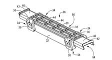
図1~4には、本発明の第一の実施形態としてのワイヤハーネス用プロテクタ10が示されている。かかるワイヤハーネス用プロテクタ10は、ベース部材12と、複数(本実施形態では4個)の挿通部構成部材14と、を備えて構成されている。なお、以下の説明において、上方とは、図1~4中の上方、下方とは、図1~4中の下方を言い、また前方とは、図1中の右斜め下方、後方とは、図1中の左斜め上方を言い、さらに長手方向とは、図1中の前後方向を言うものとする。
1 to 4 show a wire harness protector 10 as a first embodiment of the present invention. The wire harness protector 10 includes a base member 12 and a plurality (four in the present embodiment) of insertion portion constituting members 14. In the following description, “upper” means the upper side in FIGS. 1 to 4 and “lower” means the lower side in FIGS. 1 to 4, and “front” means the lower right side in FIG. 1 refers to the upper left diagonal direction, and the longitudinal direction refers to the front-rear direction in FIG.
図2~3に示されているように、ベース部材12は、略逆U字断面形状で下方に向かって開口して長手方向に延びる略樋形状を有しており、例えばポリプロピレン(PP),ポリアミド(PA)等の合成樹脂材料により射出成形等によって一体形成されている。また、ベース部材12の長手方向中央部分には、幅方向(図2中、左右方向)両側において固定片16が形成されている。かかる固定片16は、長手方向両側が切欠部18によってベース部材12から切り離されることにより基端側のみがベース部材12に連結されかつ下方に向かって突出する片持ち梁形状を有している。さらに、固定片16の突出端部の長手方向中央部には、下方斜め内方に向かって突出する略矩形平板状の係合部20が設けられており、かかる係合部20の突出先端部には内方に向かって突出すると共に長手方向の略全長に亘って略台形断面形状で延びる係合突起22が形成されている。加えて、ベース部材12の外周面24の長手方向両端部には、それぞれ複数対(本実施形態では4対)の固定部26,26が外周面24の周方向に相互に離隔すると共に外周面24に対して直立するように外方に向かって突設されている。かかる固定部26,26は、外周面24の周方向に相互に離隔するように形成されていると共に略矩形平板形状を有しており、突出端部の対向しない側の面には外方に向かって突出すると共に略三角断面形状で長手方向に延びる係合突起28が設けられている。かかる係合突起28の突出端面は、外周面24から離れるにつれて固定部26に近づくテーパ面とされている。
As shown in FIGS. 2 to 3, the base member 12 has a substantially inverted U-shaped cross section and has a substantially bowl shape that opens downward and extends in the longitudinal direction. For example, polypropylene (PP), It is integrally formed by injection molding or the like with a synthetic resin material such as polyamide (PA). In addition, fixed pieces 16 are formed at both sides in the width direction (left and right direction in FIG. 2) in the center portion in the longitudinal direction of the base member 12. The fixing piece 16 has a cantilever shape in which both sides in the longitudinal direction are separated from the base member 12 by the notches 18 so that only the base end side is connected to the base member 12 and protrudes downward. Furthermore, a substantially rectangular flat plate-like engaging portion 20 that protrudes obliquely inwardly downward is provided at the longitudinal central portion of the protruding end portion of the fixed piece 16. An engaging projection 22 is formed which protrudes inward and extends in a substantially trapezoidal cross-sectional shape over substantially the entire length in the longitudinal direction. In addition, at both ends in the longitudinal direction of the outer peripheral surface 24 of the base member 12, a plurality of pairs (four pairs in this embodiment) of fixing portions 26 and 26 are spaced apart from each other in the circumferential direction of the outer peripheral surface 24 and the outer peripheral surface. It protrudes outward so as to stand upright with respect to 24. The fixing portions 26 and 26 are formed so as to be spaced apart from each other in the circumferential direction of the outer peripheral surface 24 and have a substantially rectangular flat plate shape. Engaging protrusions 28 are provided that protrude in the longitudinal direction and extend in the longitudinal direction with a substantially triangular cross-sectional shape. The protruding end surface of the engagement protrusion 28 is a tapered surface that approaches the fixed portion 26 as the distance from the outer peripheral surface 24 increases.
一方、図4に示されているように、挿通部構成部材14は、略逆U字断面形状で下方に向かって開口して長手方向に延びる略樋形状を有しており、例えばポリプロピレン(PP),ポリアミド(PA)等の合成樹脂材料により射出成形等によって一体形成されている。かかる挿通部構成部材14は、長手方向に向かって帯状に延びる上壁部30と、上壁部30の幅方向の両側縁部から長手方向の略全長に亘って下方に向かって延び出す側壁部32と、上壁部30の長手方向の両側部分の両側縁部からそれぞれ下方に向かって突出する一対の支持脚部34,34と、を含んで構成されている。支持脚部34は、基端部が側壁部32に連結された略枠体形状を有しており、上下方向に開口する係合孔36の上側端縁部には、上方斜め内方に向かって突出する略矩形平板状の係合突起38が設けられている。また、挿通部構成部材14は、かかる一対の支持脚部34,34が設けられた上壁部30の長手方向の両側部分からさらに外方に向かって延び出す結束固定部40を有していると共に、結束固定部40の延出端部には幅方向の略全長に亘って突出する結束部材抜け止め突起42が形成されている。さらに、上壁部30は、支持脚部34が設けられた部位間において厚肉とされると共に平面視で略矩形形状で上方に向かって開口する肉抜き穴44が形成されており、支持脚部34が設けられた部分の強度を高めつつ合成樹脂材料を有利に節約している。
On the other hand, as shown in FIG. 4, the insertion portion constituting member 14 has a substantially inverted U-shaped cross-sectional shape and has a substantially bowl shape that opens downward and extends in the longitudinal direction. For example, polypropylene (PP ), A synthetic resin material such as polyamide (PA), and the like, which are integrally formed by injection molding or the like. The insertion portion constituting member 14 includes an upper wall portion 30 that extends in a strip shape in the longitudinal direction, and a side wall portion that extends downward from both side edges in the width direction of the upper wall portion 30 over substantially the entire length in the longitudinal direction. 32 and a pair of support leg portions 34 and 34 projecting downward from both side edge portions of both side portions of the upper wall portion 30 in the longitudinal direction. The support leg portion 34 has a substantially frame shape with a base end portion connected to the side wall portion 32, and the upper end edge portion of the engagement hole 36 that opens in the vertical direction faces obliquely upward and inward. An engaging projection 38 having a substantially rectangular flat plate shape is provided. Further, the insertion portion constituting member 14 has a binding fixing portion 40 that extends further outward from both longitudinal portions of the upper wall portion 30 provided with the pair of support leg portions 34, 34. At the same time, a bundling member retaining protrusion 42 is formed on the extending end of the bundling fixing portion 40 so as to project over substantially the entire length in the width direction. Further, the upper wall portion 30 is thick between the portions where the support leg portions 34 are provided, and is formed with a hollow hole 44 that opens upward in a substantially rectangular shape in plan view. The synthetic resin material is advantageously saved while increasing the strength of the portion where the portion 34 is provided.
次に、このような構成とされたベース部材12と挿通部構成部材14を含んで構成されている本実施形態のワイヤハーネス用プロテクタ10を用いたワイヤハーネス46の配索構造について、図5~6を用いて説明を行う。なお、本実施形態では、ワイヤハーネス46は、小分けされた複数の電線からなるワイヤハーネス46a~dを含んで構成されている。なお、かかるワイヤハーネス46a~dは、各端部においてコネクタ等を通じて各種電気機器等に接続されている。また、理解を容易とするため、図5~6では、ワイヤハーネス46a~dや、ワイヤハーネス46a~dから分岐する分岐電線48a~dや、固定対象であるリーンフォース50や、結束テープ55,56は、仮想線で記載している。
Next, with respect to the wiring structure of the wire harness 46 using the wire harness protector 10 of the present embodiment configured to include the base member 12 and the insertion portion constituting member 14 configured as described above, FIG. 6 is used for explanation. In the present embodiment, the wire harness 46 includes wire harnesses 46a to 46d composed of a plurality of subdivided electric wires. The wire harnesses 46a to 46d are connected to various electrical devices and the like through connectors and the like at each end. For easy understanding, in FIGS. 5 to 6, the wire harnesses 46a to 46d, the branch wires 48a to 48d branched from the wire harnesses 46a to 46d, the lean force 50 to be fixed, the binding tape 55, Reference numeral 56 denotes an imaginary line.
先ず、図5に示されているように、複数(本実施形態では4個)の挿通部構成部材14を、横方向が長手方向になるようにかつ縦方向が並列方向になるように、例えば作業台の上に上壁部30を下にして配置する。そして、複数の挿通部構成部材14の上壁部30と一対の側壁部32,32で囲まれた樋状部52に対して、上方からワイヤハーネス46を構成するワイヤハーネス46a~dの幹線54a~dをそれぞれ収容配置する。なお、この際には、ワイヤハーネス46a~dの分岐電線48a~dを、並列方向の一方側である手前側に向かって延び出すように配置する。続いて、例えば結束テープ55を用いてワイヤハーネス46a~dの幹線54a~dをそれぞれ複数の挿通部構成部材14の結束固定部40に対して位置決め保持すると共に、分岐電線48a~dについても例えば結束テープ56を用いて延出端部を結束固定する。この結果、ワイヤハーネス46に対して本実施形態の複数の挿通部構成部材14が取付けられた中間部材57が完成される。これにより、電線挿通部58の長手方向の両端部分にワイヤハーネス46a~dの幹線54a~dを容易に位置決め保持できると共に、電線挿通部58の長手方向の中央部分には結束固定部40が形成されていないことから自動的に分岐電線挿通窓60を設けることができるのである。なお、結束部材として、結束テープ55,56以外に結束バンド等の任意の結束部材が採用可能である。
First, as shown in FIG. 5, a plurality (four in this embodiment) of the insertion member constituting members 14 are arranged so that the horizontal direction is the longitudinal direction and the vertical direction is the parallel direction. It arrange | positions with the upper wall part 30 down on a work bench. Then, the trunk line 54a of the wire harnesses 46a to 46d constituting the wire harness 46 from above with respect to the bowl-shaped portion 52 surrounded by the upper wall portion 30 and the pair of side wall portions 32, 32 of the plurality of insertion portion constituting members 14. ˜d are accommodated and arranged. At this time, the branch wires 48a to 48d of the wire harnesses 46a to 46d are arranged so as to extend toward the front side, which is one side in the parallel direction. Subsequently, for example, the binding wires 55 are used to position and hold the trunks 54a to 54d of the wire harnesses 46a to 46d with respect to the binding fixing portions 40 of the plurality of insertion member constituting members 14, and the branch wires 48a to 48d are The extending end portion is bound and fixed using a binding tape 56. As a result, the intermediate member 57 in which the plurality of insertion portion constituting members 14 of the present embodiment are attached to the wire harness 46 is completed. As a result, the trunk lines 54a to 54d of the wire harnesses 46a to 46d can be easily positioned and held at both ends in the longitudinal direction of the wire insertion portion 58, and the binding fixing portion 40 is formed at the central portion in the longitudinal direction of the wire insertion portion 58. Therefore, the branch wire insertion window 60 can be automatically provided. In addition to the binding tapes 55 and 56, an arbitrary binding member such as a binding band can be used as the binding member.
次に、かかる中間部材57を裏返して上壁部30を上にした後、中間部材57を構成する複数の挿通部構成部材14をそれぞれベース部材12に対して取り付けることにより、本実施形態のワイヤハーネス用プロテクタ10を用いたワイヤハーネス46の配索構造が完成される。より詳細には、各挿通部構成部材14の一対の支持脚部34,34に設けられた係合孔36に対してベース部材12に設けられた対応する一対の固定部26,26を挿入する。これにより、固定部26の係合突起28が係合孔36の上側端縁部に設けられた係合突起38を外方に向かって弾性変形することでさらなる挿入が許容される。そして、挿入後は、支持脚部34の係合突起38が弾性復帰することにより、支持脚部34の係合孔36に対してベース部材12の固定部26が係合されて挿通部構成部材14がベース部材12に対して固定されるようになっている。かかる固定は、ドライバー等の器具を用いて解除可能であり、着脱自在となっている。なお、挿通部構成部材14とベース部材12との固定は、上記係合構造に限定されず、ボスと嵌合孔等の任意の公知の係合構造が採用可能である。また、ベース部材側の固定部を任意のピッチで複数設けておき、電線の量など必要に応じて任意の箇所に必要な数の挿通部構成部材を設けることにより、ワイヤハーネス用プロテクタの汎用性を向上させることも可能である。
Next, the intermediate member 57 is turned upside down and the upper wall portion 30 is turned up, and then the plurality of insertion portion constituting members 14 constituting the intermediate member 57 are respectively attached to the base member 12, whereby the wire of the present embodiment. The wiring structure of the wire harness 46 using the harness protector 10 is completed. More specifically, the corresponding pair of fixing portions 26 and 26 provided in the base member 12 are inserted into the engagement holes 36 provided in the pair of support legs 34 and 34 of each insertion portion constituting member 14. . Accordingly, the engagement protrusion 28 of the fixing portion 26 elastically deforms the engagement protrusion 38 provided on the upper edge portion of the engagement hole 36 outwardly, thereby allowing further insertion. After the insertion, the engagement protrusion 38 of the support leg 34 is elastically restored, whereby the fixing portion 26 of the base member 12 is engaged with the engagement hole 36 of the support leg 34 and the insertion member constituting member is inserted. 14 is fixed to the base member 12. Such fixation can be released using an instrument such as a screwdriver and is detachable. The fixing of the insertion portion constituting member 14 and the base member 12 is not limited to the above engagement structure, and any known engagement structure such as a boss and a fitting hole can be adopted. In addition, the versatility of the protector for the wire harness can be provided by providing a plurality of fixing portions on the base member side at an arbitrary pitch, and providing the necessary number of insertion portion constituent members at arbitrary locations as required, such as the amount of electric wires. It is also possible to improve.
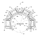
この結果、図6に示されているように、挿通部構成部材14の上壁部30がベース部材12の外周面24上に隙間を隔てて対向配置されている一方、かかる上壁部30から一対の支持脚部34,34がベース部材12に向かって突出されている。そして、上壁部30と一対の支持脚部34,34とベース部材12の外周面24によって囲まれた領域によって、電線挿通部58が構成されている。また、例えば図1に示されているように、各電線挿通部58の側面において、ベース部材12と上壁部30と長手方向一対の支持脚部34,34によって分岐電線挿通窓60が画成されている。すなわち、各電線挿通部58には、並列方向に直交する長手方向の中間部分において、長手方向に延びてかつ両側面に開口してワイヤハーネス46を構成する電線の一部によって構成される分岐電線48a~dが挿通可能な分岐電線挿通窓60が設けられているのである(図4~6参照)。したがって、各電線挿通部58はいずれも両側面に分岐電線挿通窓60を有しており、複数の電線挿通部58の並列方向の両側を分岐電線48a~dの分岐方向とすることができるのである。ここで、本実施形態では、かかる分岐電線挿通窓60の高さ寸法:hと幅寸法(長手方向):w(図1参照)の関係は、幅寸法:wは高さ寸法:hよりも大きい(w>h)ことが好ましく、より好ましくは幅寸法:wは高さ寸法:hの2倍以上、さらに好ましくは幅寸法:wは高さ寸法:hの3倍以上、であることが望ましい。なお、本実施形態では、分岐電線挿通窓60の幅寸法:wは高さ寸法:hの5倍程度となっている。
As a result, as shown in FIG. 6, the upper wall portion 30 of the insertion portion constituting member 14 is disposed oppositely on the outer peripheral surface 24 of the base member 12 with a gap between the upper wall portion 30 and the upper wall portion 30. A pair of support legs 34, 34 protrudes toward the base member 12. An electric wire insertion portion 58 is configured by a region surrounded by the upper wall portion 30, the pair of support legs 34, 34, and the outer peripheral surface 24 of the base member 12. For example, as shown in FIG. 1, on the side surface of each wire insertion portion 58, a branch wire insertion window 60 is defined by the base member 12, the upper wall portion 30, and the pair of longitudinal support legs 34, 34. Has been. That is, each electric wire insertion portion 58 includes a branched electric wire that is formed by a part of the electric wire that extends in the longitudinal direction and opens on both side surfaces to constitute the wire harness 46 in the intermediate portion in the longitudinal direction orthogonal to the parallel direction. A branch wire insertion window 60 into which 48a to 48d can be inserted is provided (see FIGS. 4 to 6). Accordingly, each of the electric wire insertion portions 58 has the branch electric wire insertion windows 60 on both side surfaces, and both sides of the plurality of electric wire insertion portions 58 in the parallel direction can be the branch direction of the branch electric wires 48a to 48d. is there. Here, in this embodiment, the relationship between the height dimension: h and the width dimension (longitudinal direction): w (see FIG. 1) of the branch wire insertion window 60 is such that the width dimension: w is higher than the height dimension: h. Preferably, the width dimension: w is at least twice the height dimension: h, more preferably the width dimension: w is at least three times the height dimension: h. desirable. In the present embodiment, the width dimension w of the branch wire insertion window 60 is about five times the height dimension h.
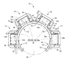
図6に示されているように、上壁部30と一対の支持脚部34,34とベース部材12の外周面24によって囲まれた領域によって電線挿通部58が構成されており、ワイヤハーネス46を構成する小分けされた複数の電線からなるワイヤハーネス46a~dが、並列配置されている複数の電線挿通部58に挿通保持されている。それゆえ、各電線挿通部58に挿通配置されるワイヤハーネス46a~dの上方への突出が抑えられることから、ワイヤハーネス用プロテクタの低背化を確実に実現できるようになっている。また、複数の電線挿通部58の並列方向の一方側(図6中、時計回り右側)が分岐電線48a~dの分岐方向とされており、分岐方向に最も遠位の電線挿通部58(ワイヤハーネス46aが挿通保持されている)では、分岐方向側(図6中、時計回り右側)の分岐電線挿通窓60を挿通して分岐電線48aが側方に引き出されている。一方、それ以外の電線挿通部58では、分岐方向側の分岐電線挿通窓60と分岐方向側に隣接配置された電線挿通部58の両側面の分岐電線挿通窓60を挿通して分岐電線48b~dが側方に引き出されるようになっている。
As shown in FIG. 6, the wire insertion portion 58 is configured by an area surrounded by the upper wall portion 30, the pair of support legs 34, 34, and the outer peripheral surface 24 of the base member 12. The wire harnesses 46a to 46d composed of a plurality of subdivided electric wires constituting the wire are inserted and held in a plurality of wire insertion portions 58 arranged in parallel. Therefore, since the upward projection of the wire harnesses 46a to 46d inserted and arranged in the respective wire insertion portions 58 is suppressed, the wire harness protector can be reliably reduced in height. In addition, one side of the plurality of electric wire insertion portions 58 in the parallel direction (clockwise right side in FIG. 6) is a branch direction of the branch electric wires 48a to 48d, and the electric wire insertion portion 58 (the wire most distal in the branch direction). In the harness 46a being inserted and held), the branch wire 48a is drawn sideways through the branch wire insertion window 60 on the branch direction side (clockwise right side in FIG. 6). On the other hand, in the other wire insertion portion 58, the branch wire insertion window 60 is inserted through the branch wire insertion window 60 on both sides of the branch wire insertion window 60 on the branch direction side and the wire insertion portion 58 arranged adjacent to the branch direction side. d is pulled out to the side.
さらに、図5に示されているように、複数の電線挿通部58における分岐電線48a~dの引き出し位置が、長手方向(図5中、左右方向)で相互に異ならされている。これにより、各電線挿通部58から分岐する分岐電線48a~d同士が重なり合うことが有利に防止されていることから、分岐電線48a~dの一層の低背化が可能となっている。加えて、電線挿通部58を挿通するワイヤハーネス46を構成するワイヤハーネス46a~dの断面積Sa~dが、分岐方向(図6中、時計回り左側)に向かって次第に大きくされている(図6参照、Sa>Sb>Sc>Sd)。すなわち、より多くの分岐電線48a~cを乗り越える必要があるワイヤハーネス46a~dの幹線54a~dがより小面積とされていることから、各電線挿通部58を挿通するワイヤハーネス46a~dの幹線54a~dおよび分岐電線48a~cの断面積の平準化を図ることができるので、低背化を有利に実現できる。
Furthermore, as shown in FIG. 5, the lead-out positions of the branch wires 48a to 48d in the plurality of wire insertion portions 58 are different from each other in the longitudinal direction (left-right direction in FIG. 5). This advantageously prevents the branch wires 48a to 48d branched from the wire insertion portions 58 from overlapping each other, thereby further reducing the height of the branch wires 48a to 48d. In addition, the cross-sectional areas Sa to d of the wire harnesses 46a to 46d constituting the wire harness 46 that passes through the wire insertion portion 58 are gradually increased toward the branch direction (clockwise left side in FIG. 6) (see FIG. 6). 6, Sa> Sb> Sc> Sd). That is, since the trunk lines 54a to 54d of the wire harnesses 46a to 46d that need to get over more branch wires 48a to 48c have a smaller area, the wire harnesses 46a to 46d that pass through the respective wire insertion portions 58 are used. Since the cross-sectional areas of the main lines 54a to 54d and the branch wires 48a to 48c can be leveled, a reduction in height can be realized advantageously.
最後に、図6に示されているように、このようにワイヤハーネス46が配索された本実施形態のワイヤハーネス用プロテクタ10が、固定対象であるリーンフォース50に固定されるようになっている。より詳細には、長手方向に延び出す筒状のリーンフォース50の外周面62に対して、ベース部材12の長手方向をリーンフォース50の長手方向に沿わせた状態で上方から配設した後、ベース部材12をリーンフォース50に向かって押し込む。これにより、ベース部材12の一対の固定片16,16が相互に離隔する方向に弾性変形してさらなる挿入が許容され、一対の固定片16,16の係合突起22がリーンフォース50の外周面62に設けられた図示しない取付孔に嵌合することにより、弾性復帰する。この結果、リーンフォース50に対して本実施形態のワイヤハーネス用プロテクタ10を安定的に保持できるようになっている。このように、例えばリーンフォース50のような平坦でない固定対象に対しても、ベース部材12の形状を固定対象の形状に合わせることにより、ワイヤハーネス用プロテクタ10を容易に取り付けることができるようになっているのである。なお、上記実施形態では、固定対象として筒状のリーンフォース50を例示して説明を行ったが、固定対象が車体フレーム等であってもよく、その形状も筒状に限定されず任意の形状のものが採用可能であることは勿論である。
Finally, as shown in FIG. 6, the wire harness protector 10 of the present embodiment in which the wire harness 46 is thus wired is fixed to the lean force 50 that is a fixing target. Yes. More specifically, after the longitudinal direction of the base member 12 is arranged along the longitudinal direction of the lean force 50 with respect to the outer peripheral surface 62 of the tubular reinforcement 50 extending in the longitudinal direction, The base member 12 is pushed toward the lean force 50. As a result, the pair of fixed pieces 16 and 16 of the base member 12 are elastically deformed in a direction away from each other to allow further insertion, and the engagement protrusions 22 of the pair of fixed pieces 16 and 16 become the outer peripheral surface of the lean force 50. By fitting in a mounting hole (not shown) provided in 62, the elastic return is achieved. As a result, the wire harness protector 10 of the present embodiment can be stably held with respect to the lean force 50. As described above, the wire harness protector 10 can be easily attached to a non-flat fixed object such as the lean force 50 by matching the shape of the base member 12 to the shape of the fixed object. -ing In the above-described embodiment, the cylindrical reinforcement 50 has been described as an example of the fixing target. However, the fixing target may be a body frame or the like, and the shape is not limited to the cylindrical shape, but may be any shape. Of course, it can be adopted.
このような構成とされた本実施形態のワイヤハーネス用プロテクタ10を用いたワイヤハーネス46の配索構造によれば、ワイヤハーネス46が小分けされた複数の電線からなるワイヤハーネス46a~dを含んで構成されており、かかるワイヤハーネス46a~dが収容される複数の電線挿通部58が並列配置されている。これにより、ワイヤハーネス46を構成する電線が増加しても、ワイヤハーネス用プロテクタ10の低背化を有利に維持できるようになっているのである。
According to the wiring structure of the wire harness 46 using the wire harness protector 10 of the present embodiment having such a configuration, the wire harness 46 includes the wire harnesses 46a to 46d composed of a plurality of divided electric wires. A plurality of wire insertion portions 58 in which the wire harnesses 46a to 46d are accommodated are arranged in parallel. Thereby, even if the electric wire which comprises the wire harness 46 increases, the height reduction of the protector 10 for wire harnesses can be maintained advantageously.
以上、本発明の実施形態について詳述したが、本発明はこれらの具体的な記載によって限定されない。例えば、本実施形態のワイヤハーネス用プロテクタ10を用いたワイヤハーネス46の配索構造では、ワイヤハーネス46を構成する小分けされた複数の電線からなるワイヤハーネス46a~dの分岐電線48a~dの分岐方向は、複数の電線挿通部58の並列方向の一方側(図6中、時計回り右側)とされていた。しかしながら、図7に示す本実施形態のワイヤハーネス用プロテクタ10を用いたワイヤハーネス46の他の配索構造のように、分岐電線48a~dの分岐方向が複数の電線挿通部58の並列方向の他方側(図7中、反時計回り左側)とされていてもよい。あるいは、図8~9に示す本実施形態のワイヤハーネス用プロテクタ10を用いたワイヤハーネス46の別の配索構造のように、分岐電線48a~dの分岐方向が複数の電線挿通部58の並列方向の両側(図9中、時計回り右側および反時計回り左側)とされていてもよい。このように、本実施形態のワイヤハーネス用プロテクタ10では、複数の電線挿通部58の並列方向の両側が分岐方向となるように、各電線挿通部58の何れもが、両側面に分岐電線挿通窓60を備えていることから、ワイヤハーネス用プロテクタ10の方向性が低減されて、汎用性が向上されているのである。
As mentioned above, although embodiment of this invention was explained in full detail, this invention is not limited by these specific description. For example, in the wiring structure of the wire harness 46 using the wire harness protector 10 according to the present embodiment, the branch wires 48a to 48d of the wire harnesses 46a to 46d composed of a plurality of subdivided wires constituting the wire harness 46 are branched. The direction was set to one side of the plurality of electric wire insertion portions 58 in the parallel direction (the clockwise right side in FIG. 6). However, like the other wiring structure of the wire harness 46 using the wire harness protector 10 of the present embodiment shown in FIG. 7, the branching direction of the branch wires 48a to 48d is the parallel direction of the plurality of wire insertion portions 58. The other side (in FIG. 7, counterclockwise left side) may be used. Alternatively, as in another wiring structure of the wire harness 46 using the wire harness protector 10 of the present embodiment shown in FIGS. 8 to 9, the branching directions of the branch wires 48a to 48d are parallel to the plurality of wire insertion portions 58. Both sides of the direction (in FIG. 9, clockwise right side and counterclockwise left side) may be used. As described above, in the wire harness protector 10 of the present embodiment, each of the electric wire insertion portions 58 is inserted on both side surfaces so that both sides of the plurality of electric wire insertion portions 58 in the parallel direction are branched. Since the window 60 is provided, the directivity of the wire harness protector 10 is reduced and the versatility is improved.
また、本実施形態のワイヤハーネス用プロテクタ10では、各電線挿通部58の何れもが両側面に分岐電線挿通窓60を備えていたが、図10~11に示す本発明の第二の実施形態としてのワイヤハーネス用プロテクタ68のように、分岐方向(図11中、時計回り右方向)から最も遠位の電線挿通部64を構成する挿通部構成部材66には、少なくとも分岐方向側(図11中、時計回り右側)の側面に分岐電線挿通窓60が設けられていればよい。すなわち、図11に示されているように、分岐方向側(図11中、時計回り右側)とは反対側の側面には分岐電線挿通窓60が設けられていなくてもよい。さらに、並列方向の中央部分から両側にそれぞれ分岐電線が引き出される場合には、中央部分の両側に位置する各電線挿通部58が分岐方向から最遠位の電線挿通部58になることから、それらの分岐方向側の側面のみに分岐電線挿通窓60が設けられていてもよい。
Further, in the wire harness protector 10 of the present embodiment, each of the electric wire insertion portions 58 is provided with the branch electric wire insertion windows 60 on both side surfaces. However, the second embodiment of the present invention shown in FIGS. Like the wire harness protector 68, the insertion portion constituting member 66 constituting the wire insertion portion 64 that is the most distal from the branch direction (clockwise right direction in FIG. 11) is at least in the branch direction side (FIG. 11). The branch electric wire insertion window 60 should just be provided in the side surface of the inside (clockwise right side). That is, as shown in FIG. 11, the branch wire insertion window 60 may not be provided on the side surface opposite to the branch direction side (clockwise right side in FIG. 11). Furthermore, when branch wires are drawn out from the central portion in the parallel direction to both sides, the wire insertion portions 58 located on both sides of the central portion become the most distal wire insertion portions 58 from the branch direction. The branch wire insertion window 60 may be provided only on the side surface on the branch direction side.
加えて、上記実施形態では、電線挿通部58は上壁部30と一対の支持脚部34,34とベース部材12の外周面24によって囲まれた領域によって構成されていたが、電線挿通部が上壁部と一対の支持脚部によって構成されかつ上方に開口するように形成されていてもよい。これにより、ワイヤハーネス用プロテクタを構成後にワイヤハーネス46を上方から組み付けることが可能となる。
In addition, in the above embodiment, the wire insertion portion 58 is configured by a region surrounded by the upper wall portion 30, the pair of support legs 34, 34, and the outer peripheral surface 24 of the base member 12. It may be formed by an upper wall portion and a pair of support leg portions and open upward. This makes it possible to assemble the wire harness 46 from above after the wire harness protector is configured.
また、上記実施形態では、ワイヤハーネス用プロテクタ10はベース部材12を有していたが、なくてもよい。例えば、複数の電線挿通部58をそれぞれ側面に分岐電線挿通窓60が開口形成された筒体によって構成し、電線挿通部58を任意の連結部材によって並列方向に連結することにより、ワイヤハーネス用プロテクタが構成されていてもよい。
In the above embodiment, the wire harness protector 10 has the base member 12, but may not be provided. For example, the wire harness protector for the wire harness is formed by configuring each of the plurality of wire insertion portions 58 with a cylindrical body in which branch wire insertion windows 60 are formed on the side surfaces and connecting the wire insertion portions 58 in parallel with an arbitrary connecting member. May be configured.
10,68:ワイヤハーネス用プロテクタ、12:ベース部材、14,66:挿通部構成部材、26:固定部、30:上壁部、34:支持脚部、46:ワイヤハーネス、46a~d:ワイヤハーネス、48a~d:分岐電線、50:リーンフォース(固定対象)、58,64:電線挿通部、60:分岐電線挿通窓
DESCRIPTION OF SYMBOLS 10,68: Protector for wire harnesses, 12: Base member, 14,66: Insertion part component member, 26: Fixing part, 30: Upper wall part, 34: Support leg part, 46: Wire harness, 46a-d: Wire Harness, 48a to d: Branch wire, 50: Reinforce (fixed), 58, 64: Wire insertion part, 60: Branch wire insertion window
Claims (6)
- ワイヤハーネスを構成する複数の電線が小分けされて収容される複数の電線挿通部を有し、
前記複数の電線挿通部が並列配置されている一方、
前記複数の電線挿通部の並列方向の少なくとも一方側が前記電線の分岐方向とされており、
前記分岐方向から最も遠位の前記電線挿通部を除く各前記電線挿通部には、前記並列方向に直交する長手方向の中間部分において、前記長手方向に延びてかつ両側面に開口して前記電線の一部によって構成される分岐電線が挿通可能な分岐電線挿通窓が設けられている一方、
前記分岐方向から最も遠位の前記電線挿通部には、少なくとも前記分岐方向側の側面に前記分岐電線挿通窓が設けられているワイヤハーネス用プロテクタ。 Having a plurality of electric wire insertion portions in which a plurality of electric wires constituting the wire harness are subdivided and accommodated,
While the plurality of wire insertion portions are arranged in parallel,
At least one side of the parallel direction of the plurality of electric wire insertion portions is a branch direction of the electric wire,
Each of the wire insertion portions excluding the wire insertion portion farthest from the branching direction extends in the longitudinal direction and opens on both side surfaces in the middle portion in the longitudinal direction orthogonal to the parallel direction. While a branch wire insertion window into which a branch wire constituted by a part of the branch wire can be inserted is provided,
The wire harness protector in which the branch wire insertion window is provided at least on a side surface on the branch direction side in the wire insertion portion farthest from the branch direction. - 各前記電線挿通部がいずれも前記両側面に前記分岐電線挿通窓を有しており、前記複数の電線挿通部の並列方向の両側を前記電線の分岐方向とすることができる請求項1に記載のワイヤハーネス用プロテクタ。 2. The wire insertion portion according to claim 1, wherein each of the wire insertion portions has the branch wire insertion window on both side surfaces, and both sides in the parallel direction of the plurality of wire insertion portions can be the branch direction of the wires. Wire harness protector.
- 固定対象に固定されるベース部材と、
前記ベース部材上に隙間を隔てて対向配置される長手状の上壁部と、該上壁部の長手方向の両側部分の両側縁部からそれぞれ前記ベース部材に向かって突出する一対の支持脚部とを含んで構成された挿通部構成部材の複数とをさらに備えており、
各前記挿通部構成部材の前記一対の支持脚部が前記ベース部材に設けられた複数の固定部に対してそれぞれ着脱自在に固定されることにより、各前記電線挿通部が構成され、各前記電線挿通部の前記側面において、前記ベース部材と前記上壁部と長手方向両側の前記支持脚部によって前記分岐電線挿通窓が画成されている請求項1または2に記載のワイヤハーネス用プロテクタ。 A base member fixed to a fixed object;
A longitudinal upper wall portion disposed opposite to the base member with a gap, and a pair of support legs projecting from both side edge portions of both side portions in the longitudinal direction of the upper wall portion toward the base member. And a plurality of insertion portion constituting members configured to include,
Each of the wire insertion portions is configured by detachably fixing the pair of support leg portions of each of the insertion portion constituting members to a plurality of fixing portions provided on the base member. The protector for a wire harness according to claim 1 or 2, wherein the branch wire insertion window is defined by the base member, the upper wall portion, and the support leg portions on both sides in the longitudinal direction on the side surface of the insertion portion. - ワイヤハーネス用プロテクタを用いたワイヤハーネスの配索構造であって、
前記ワイヤハーネス用プロテクタとして請求項1~3の何れか1項に記載のワイヤハーネス用プロテクタを用い、
前記ワイヤハーネスを構成する複数の電線が小分けされて前記複数の電線挿通部に挿通保持されている一方、
前記分岐方向に最も遠位の前記電線挿通部では、前記分岐方向側の前記分岐電線挿通窓を挿通して前記分岐電線が側方に引き出されている一方、それ以外の前記電線挿通部では、前記分岐方向側の前記分岐電線挿通窓と前記分岐方向側に隣接配置された前記電線挿通部の両側面の前記分岐電線挿通窓を挿通して前記分岐電線が側方に引き出されているワイヤハーネスの配索構造。 A wiring harness wiring structure using a wire harness protector,
The wire harness protector according to any one of claims 1 to 3, wherein the wire harness protector is used.
While the plurality of electric wires constituting the wire harness are subdivided and inserted and held in the plurality of electric wire insertion portions,
In the wire insertion portion farthest in the branch direction, the branch wire is pulled out sideways through the branch wire insertion window on the branch direction side, while in the other wire insertion portion, A wire harness in which the branch wire is pulled out laterally through the branch wire insertion window on both sides of the branch wire insertion window on both sides of the branch wire insertion window on the branch direction side and the branch direction side. The routing structure. - 複数の前記電線挿通部における前記分岐電線の引き出し位置が、前記長手方向で相互に異ならされている請求項4に記載のワイヤハーネスの配索構造。 The wire harness routing structure according to claim 4, wherein the drawing positions of the branch wires in the plurality of wire insertion portions are different from each other in the longitudinal direction.
- 各前記電線挿通部を挿通する小分けされた前記ワイヤハーネスの断面積が、前記分岐方向に向かって次第に大きくされている請求項4または5に記載のワイヤハーネスの配索構造。 The wiring structure of the wire harness according to claim 4 or 5, wherein a cross-sectional area of the subdivided wire harness inserted through each of the electric wire insertion portions is gradually increased toward the branch direction.
Priority Applications (3)
| Application Number | Priority Date | Filing Date | Title |
|---|---|---|---|
| CN201880091221.0A CN111886765B (en) | 2018-03-16 | 2018-12-21 | Protector for wire harness and wiring structure of wire harness using the same |
| DE112018007293.2T DE112018007293T5 (en) | 2018-03-16 | 2018-12-21 | Harness protector and harness laying structure using the same |
| US16/976,111 US11485300B2 (en) | 2018-03-16 | 2018-12-21 | Wire harness protector and routing structure of wire harness using wire harness protector |
Applications Claiming Priority (2)
| Application Number | Priority Date | Filing Date | Title |
|---|---|---|---|
| JP2018048929A JP6691670B2 (en) | 2018-03-16 | 2018-03-16 | Wire harness protector and wire harness wiring structure using the same |
| JP2018-048929 | 2018-03-16 |
Publications (1)
| Publication Number | Publication Date |
|---|---|
| WO2019176221A1 true WO2019176221A1 (en) | 2019-09-19 |
Family
ID=67907734
Family Applications (1)
| Application Number | Title | Priority Date | Filing Date |
|---|---|---|---|
| PCT/JP2018/047233 WO2019176221A1 (en) | 2018-03-16 | 2018-12-21 | Wire harness protector and wire harness routing structure using same |
Country Status (5)
| Country | Link |
|---|---|
| US (1) | US11485300B2 (en) |
| JP (1) | JP6691670B2 (en) |
| CN (1) | CN111886765B (en) |
| DE (1) | DE112018007293T5 (en) |
| WO (1) | WO2019176221A1 (en) |
Families Citing this family (2)
| Publication number | Priority date | Publication date | Assignee | Title |
|---|---|---|---|---|
| JP6870533B2 (en) * | 2017-08-23 | 2021-05-12 | 株式会社オートネットワーク技術研究所 | Assembly structure of wire harness with electrical parts and wire harness with electrical parts |
| JP6943737B2 (en) * | 2017-11-21 | 2021-10-06 | 古河電気工業株式会社 | Exterior body for electric wires and wire harness with exterior body |
Citations (3)
| Publication number | Priority date | Publication date | Assignee | Title |
|---|---|---|---|---|
| JPH0321143Y2 (en) * | 1984-07-30 | 1991-05-08 | ||
| JP2003054330A (en) * | 2001-06-06 | 2003-02-26 | Furukawa Electric Co Ltd:The | Wire harness assembly type vehicle parts |
| JP2015046991A (en) * | 2013-08-28 | 2015-03-12 | 株式会社オートネットワーク技術研究所 | Protector |
Family Cites Families (15)
| Publication number | Priority date | Publication date | Assignee | Title |
|---|---|---|---|---|
| JPS6052105B2 (en) | 1982-12-28 | 1985-11-18 | 住友特殊金属株式会社 | Oxide hot isostatic pressing method |
| JPH0670415U (en) | 1993-03-04 | 1994-09-30 | 矢崎総業株式会社 | Electric wire housing protector having a biting prevention structure |
| DE60119664T2 (en) | 2000-11-02 | 2007-05-10 | The Furukawa Electric Co., Ltd., | harness |
| JP3752148B2 (en) * | 2000-12-11 | 2006-03-08 | 矢崎総業株式会社 | Harness protector |
| JP3695354B2 (en) * | 2001-06-08 | 2005-09-14 | 住友電装株式会社 | Clamp for wire harness |
| JP4124104B2 (en) * | 2003-11-14 | 2008-07-23 | 住友電装株式会社 | Protector |
| JP2007076576A (en) * | 2005-09-16 | 2007-03-29 | Sumitomo Wiring Syst Ltd | Structure for routing wire harness |
| US7939759B2 (en) * | 2008-04-22 | 2011-05-10 | Henry Stephen K | Cable protector with removable dividers |
| GB0915552D0 (en) * | 2009-09-07 | 2009-10-07 | Icore Internat Ltd | Cable-routing |
| JP5657959B2 (en) * | 2010-09-02 | 2015-01-21 | 矢崎総業株式会社 | Wire harness mounting structure |
| JP5768379B2 (en) | 2011-01-19 | 2015-08-26 | 住友電装株式会社 | Protector for wire harness |
| JP5915250B2 (en) * | 2012-02-23 | 2016-05-11 | 住友電装株式会社 | Wiring harness wiring structure and method of forming the wiring structure |
| JP6286141B2 (en) * | 2013-05-29 | 2018-02-28 | 矢崎総業株式会社 | Bus bar module and power supply |
| JP6947100B2 (en) * | 2018-03-28 | 2021-10-13 | 株式会社オートネットワーク技術研究所 | Conductive path |
| JP6607282B1 (en) * | 2018-05-30 | 2019-11-20 | 株式会社オートネットワーク技術研究所 | Wiring member |
-
2018
- 2018-03-16 JP JP2018048929A patent/JP6691670B2/en active Active
- 2018-12-21 WO PCT/JP2018/047233 patent/WO2019176221A1/en active Application Filing
- 2018-12-21 CN CN201880091221.0A patent/CN111886765B/en active Active
- 2018-12-21 US US16/976,111 patent/US11485300B2/en active Active
- 2018-12-21 DE DE112018007293.2T patent/DE112018007293T5/en active Pending
Patent Citations (3)
| Publication number | Priority date | Publication date | Assignee | Title |
|---|---|---|---|---|
| JPH0321143Y2 (en) * | 1984-07-30 | 1991-05-08 | ||
| JP2003054330A (en) * | 2001-06-06 | 2003-02-26 | Furukawa Electric Co Ltd:The | Wire harness assembly type vehicle parts |
| JP2015046991A (en) * | 2013-08-28 | 2015-03-12 | 株式会社オートネットワーク技術研究所 | Protector |
Also Published As
| Publication number | Publication date |
|---|---|
| CN111886765B (en) | 2021-10-29 |
| CN111886765A (en) | 2020-11-03 |
| US20200406839A1 (en) | 2020-12-31 |
| DE112018007293T5 (en) | 2021-01-28 |
| JP6691670B2 (en) | 2020-05-13 |
| JP2019161965A (en) | 2019-09-19 |
| US11485300B2 (en) | 2022-11-01 |
Similar Documents
| Publication | Publication Date | Title |
|---|---|---|
| US7507905B2 (en) | Electrical junction box | |
| US8124887B2 (en) | Protector | |
| CN102934305A (en) | Wiring harness and method of assembling the same | |
| CN103208760A (en) | Wire harness and wire fitting | |
| JP2007099007A (en) | Cable routing structure of wire harness | |
| WO2019176221A1 (en) | Wire harness protector and wire harness routing structure using same | |
| JP4597564B2 (en) | Clip structure and fixing method | |
| JP2019161965A5 (en) | ||
| JP6857338B2 (en) | Wire harness protector and harness assembly | |
| JP2020115743A (en) | Protector for wiring harness and wiring structure of wiring harness using the same | |
| JP2020115743A5 (en) | ||
| US20220169190A1 (en) | Wiring harness unit and wiring harness mounting structure | |
| JP2015033314A (en) | Assembling structure of binding band | |
| WO2016117366A1 (en) | Harness protector | |
| JP5979036B2 (en) | Wire harness wiring device for slide sheet | |
| JP2017135813A (en) | Wiring harness with protector | |
| JP6702912B2 (en) | Electric wire protection case and slide sheet | |
| JP7172972B2 (en) | Connector holder and wire harness | |
| KR200466124Y1 (en) | Multipurpose combination type clip | |
| WO2017090597A1 (en) | Electric connection box | |
| JP6014469B2 (en) | Wiring harness wiring structure | |
| JP5920663B2 (en) | Electrical junction box | |
| KR101959912B1 (en) | Battery pack mounting type protector | |
| KR101959910B1 (en) | Battery pack mounting type protector | |
| KR101959911B1 (en) | Battery pack mounting type protector |
Legal Events
| Date | Code | Title | Description |
|---|---|---|---|
| 121 | Ep: the epo has been informed by wipo that ep was designated in this application |
Ref document number: 18909848 Country of ref document: EP Kind code of ref document: A1 |
|
| DPE1 | Request for preliminary examination filed after expiration of 19th month from priority date (pct application filed from 20040101) | ||
| 122 | Ep: pct application non-entry in european phase |
Ref document number: 18909848 Country of ref document: EP Kind code of ref document: A1 |