WO2019172160A1 - Electrolysis electrode and method for manufacturing same - Google Patents
Electrolysis electrode and method for manufacturing same Download PDFInfo
- Publication number
- WO2019172160A1 WO2019172160A1 PCT/JP2019/008289 JP2019008289W WO2019172160A1 WO 2019172160 A1 WO2019172160 A1 WO 2019172160A1 JP 2019008289 W JP2019008289 W JP 2019008289W WO 2019172160 A1 WO2019172160 A1 WO 2019172160A1
- Authority
- WO
- WIPO (PCT)
- Prior art keywords
- nickel
- electrolysis
- intermediate layer
- electrode
- conductive substrate
- Prior art date
Links
Images


Classifications
-
- C—CHEMISTRY; METALLURGY
- C25—ELECTROLYTIC OR ELECTROPHORETIC PROCESSES; APPARATUS THEREFOR
- C25B—ELECTROLYTIC OR ELECTROPHORETIC PROCESSES FOR THE PRODUCTION OF COMPOUNDS OR NON-METALS; APPARATUS THEREFOR
- C25B11/00—Electrodes; Manufacture thereof not otherwise provided for
- C25B11/04—Electrodes; Manufacture thereof not otherwise provided for characterised by the material
- C25B11/051—Electrodes formed of electrocatalysts on a substrate or carrier
- C25B11/073—Electrodes formed of electrocatalysts on a substrate or carrier characterised by the electrocatalyst material
- C25B11/075—Electrodes formed of electrocatalysts on a substrate or carrier characterised by the electrocatalyst material consisting of a single catalytic element or catalytic compound
- C25B11/077—Electrodes formed of electrocatalysts on a substrate or carrier characterised by the electrocatalyst material consisting of a single catalytic element or catalytic compound the compound being a non-noble metal oxide
- C25B11/0771—Electrodes formed of electrocatalysts on a substrate or carrier characterised by the electrocatalyst material consisting of a single catalytic element or catalytic compound the compound being a non-noble metal oxide of the spinel type
-
- C—CHEMISTRY; METALLURGY
- C23—COATING METALLIC MATERIAL; COATING MATERIAL WITH METALLIC MATERIAL; CHEMICAL SURFACE TREATMENT; DIFFUSION TREATMENT OF METALLIC MATERIAL; COATING BY VACUUM EVAPORATION, BY SPUTTERING, BY ION IMPLANTATION OR BY CHEMICAL VAPOUR DEPOSITION, IN GENERAL; INHIBITING CORROSION OF METALLIC MATERIAL OR INCRUSTATION IN GENERAL
- C23C—COATING METALLIC MATERIAL; COATING MATERIAL WITH METALLIC MATERIAL; SURFACE TREATMENT OF METALLIC MATERIAL BY DIFFUSION INTO THE SURFACE, BY CHEMICAL CONVERSION OR SUBSTITUTION; COATING BY VACUUM EVAPORATION, BY SPUTTERING, BY ION IMPLANTATION OR BY CHEMICAL VAPOUR DEPOSITION, IN GENERAL
- C23C18/00—Chemical coating by decomposition of either liquid compounds or solutions of the coating forming compounds, without leaving reaction products of surface material in the coating; Contact plating
- C23C18/02—Chemical coating by decomposition of either liquid compounds or solutions of the coating forming compounds, without leaving reaction products of surface material in the coating; Contact plating by thermal decomposition
- C23C18/12—Chemical coating by decomposition of either liquid compounds or solutions of the coating forming compounds, without leaving reaction products of surface material in the coating; Contact plating by thermal decomposition characterised by the deposition of inorganic material other than metallic material
- C23C18/1204—Chemical coating by decomposition of either liquid compounds or solutions of the coating forming compounds, without leaving reaction products of surface material in the coating; Contact plating by thermal decomposition characterised by the deposition of inorganic material other than metallic material inorganic material, e.g. non-oxide and non-metallic such as sulfides, nitrides based compounds
- C23C18/1208—Oxides, e.g. ceramics
- C23C18/1216—Metal oxides
-
- C—CHEMISTRY; METALLURGY
- C25—ELECTROLYTIC OR ELECTROPHORETIC PROCESSES; APPARATUS THEREFOR
- C25B—ELECTROLYTIC OR ELECTROPHORETIC PROCESSES FOR THE PRODUCTION OF COMPOUNDS OR NON-METALS; APPARATUS THEREFOR
- C25B1/00—Electrolytic production of inorganic compounds or non-metals
- C25B1/01—Products
- C25B1/02—Hydrogen or oxygen
- C25B1/04—Hydrogen or oxygen by electrolysis of water
-
- C—CHEMISTRY; METALLURGY
- C25—ELECTROLYTIC OR ELECTROPHORETIC PROCESSES; APPARATUS THEREFOR
- C25B—ELECTROLYTIC OR ELECTROPHORETIC PROCESSES FOR THE PRODUCTION OF COMPOUNDS OR NON-METALS; APPARATUS THEREFOR
- C25B11/00—Electrodes; Manufacture thereof not otherwise provided for
- C25B11/04—Electrodes; Manufacture thereof not otherwise provided for characterised by the material
- C25B11/051—Electrodes formed of electrocatalysts on a substrate or carrier
- C25B11/052—Electrodes comprising one or more electrocatalytic coatings on a substrate
-
- C—CHEMISTRY; METALLURGY
- C25—ELECTROLYTIC OR ELECTROPHORETIC PROCESSES; APPARATUS THEREFOR
- C25B—ELECTROLYTIC OR ELECTROPHORETIC PROCESSES FOR THE PRODUCTION OF COMPOUNDS OR NON-METALS; APPARATUS THEREFOR
- C25B11/00—Electrodes; Manufacture thereof not otherwise provided for
- C25B11/04—Electrodes; Manufacture thereof not otherwise provided for characterised by the material
- C25B11/051—Electrodes formed of electrocatalysts on a substrate or carrier
- C25B11/055—Electrodes formed of electrocatalysts on a substrate or carrier characterised by the substrate or carrier material
- C25B11/069—Electrodes formed of electrocatalysts on a substrate or carrier characterised by the substrate or carrier material consisting of at least one single element and at least one compound; consisting of two or more compounds
-
- C—CHEMISTRY; METALLURGY
- C25—ELECTROLYTIC OR ELECTROPHORETIC PROCESSES; APPARATUS THEREFOR
- C25B—ELECTROLYTIC OR ELECTROPHORETIC PROCESSES FOR THE PRODUCTION OF COMPOUNDS OR NON-METALS; APPARATUS THEREFOR
- C25B11/00—Electrodes; Manufacture thereof not otherwise provided for
- C25B11/04—Electrodes; Manufacture thereof not otherwise provided for characterised by the material
- C25B11/051—Electrodes formed of electrocatalysts on a substrate or carrier
- C25B11/073—Electrodes formed of electrocatalysts on a substrate or carrier characterised by the electrocatalyst material
- C25B11/075—Electrodes formed of electrocatalysts on a substrate or carrier characterised by the electrocatalyst material consisting of a single catalytic element or catalytic compound
- C25B11/077—Electrodes formed of electrocatalysts on a substrate or carrier characterised by the electrocatalyst material consisting of a single catalytic element or catalytic compound the compound being a non-noble metal oxide
- C25B11/0773—Electrodes formed of electrocatalysts on a substrate or carrier characterised by the electrocatalyst material consisting of a single catalytic element or catalytic compound the compound being a non-noble metal oxide of the perovskite type
-
- C—CHEMISTRY; METALLURGY
- C25—ELECTROLYTIC OR ELECTROPHORETIC PROCESSES; APPARATUS THEREFOR
- C25B—ELECTROLYTIC OR ELECTROPHORETIC PROCESSES FOR THE PRODUCTION OF COMPOUNDS OR NON-METALS; APPARATUS THEREFOR
- C25B11/00—Electrodes; Manufacture thereof not otherwise provided for
- C25B11/04—Electrodes; Manufacture thereof not otherwise provided for characterised by the material
- C25B11/051—Electrodes formed of electrocatalysts on a substrate or carrier
- C25B11/073—Electrodes formed of electrocatalysts on a substrate or carrier characterised by the electrocatalyst material
- C25B11/091—Electrodes formed of electrocatalysts on a substrate or carrier characterised by the electrocatalyst material consisting of at least one catalytic element and at least one catalytic compound; consisting of two or more catalytic elements or catalytic compounds
- C25B11/093—Electrodes formed of electrocatalysts on a substrate or carrier characterised by the electrocatalyst material consisting of at least one catalytic element and at least one catalytic compound; consisting of two or more catalytic elements or catalytic compounds at least one noble metal or noble metal oxide and at least one non-noble metal oxide
-
- Y—GENERAL TAGGING OF NEW TECHNOLOGICAL DEVELOPMENTS; GENERAL TAGGING OF CROSS-SECTIONAL TECHNOLOGIES SPANNING OVER SEVERAL SECTIONS OF THE IPC; TECHNICAL SUBJECTS COVERED BY FORMER USPC CROSS-REFERENCE ART COLLECTIONS [XRACs] AND DIGESTS
- Y02—TECHNOLOGIES OR APPLICATIONS FOR MITIGATION OR ADAPTATION AGAINST CLIMATE CHANGE
- Y02E—REDUCTION OF GREENHOUSE GAS [GHG] EMISSIONS, RELATED TO ENERGY GENERATION, TRANSMISSION OR DISTRIBUTION
- Y02E60/00—Enabling technologies; Technologies with a potential or indirect contribution to GHG emissions mitigation
- Y02E60/30—Hydrogen technology
- Y02E60/36—Hydrogen production from non-carbon containing sources, e.g. by water electrolysis
-
- Y—GENERAL TAGGING OF NEW TECHNOLOGICAL DEVELOPMENTS; GENERAL TAGGING OF CROSS-SECTIONAL TECHNOLOGIES SPANNING OVER SEVERAL SECTIONS OF THE IPC; TECHNICAL SUBJECTS COVERED BY FORMER USPC CROSS-REFERENCE ART COLLECTIONS [XRACs] AND DIGESTS
- Y02—TECHNOLOGIES OR APPLICATIONS FOR MITIGATION OR ADAPTATION AGAINST CLIMATE CHANGE
- Y02P—CLIMATE CHANGE MITIGATION TECHNOLOGIES IN THE PRODUCTION OR PROCESSING OF GOODS
- Y02P20/00—Technologies relating to chemical industry
- Y02P20/10—Process efficiency
- Y02P20/133—Renewable energy sources, e.g. sunlight
Definitions
- the present invention relates to an electrode for electrolysis and a manufacturing method thereof.
- Hydrogen is a secondary energy that is suitable for storage and transportation, and has a low environmental load, and therefore, interest has been focused on a hydrogen energy system using hydrogen as an energy carrier.
- hydrogen is mainly produced by steam reforming of fossil fuels, but from the viewpoint of global warming and fossil fuel depletion, the importance of alkaline water electrolysis using renewable energy as a power source has increased. Yes.
- Water electrolysis is roughly divided into two. One is alkaline water electrolysis, and a high-concentration alkaline aqueous solution is used for the electrolyte. The other is solid polymer water electrolysis, in which a solid polymer membrane (SPE) is used as the electrolyte.
- SPE solid polymer membrane
- a highly concentrated aqueous alkali solution increases in electrical conductivity with increasing temperature, but also increases in corrosivity. For this reason, the upper limit of the operating temperature is suppressed to about 80 to 90 ° C.
- the electrolysis performance has a current density of 0.3-0. It is improved to about 1.7 to 1.9 V (efficiency 78 to 87%) at .4 Acm ⁇ 2 .
- Non-Patent Documents 1 and 2 As an anode for alkaline water electrolysis, a nickel-based material that is stable in a high-concentration alkaline aqueous solution is used. In the case of alkaline water electrolysis using a stable power source, the nickel-based anode must have a life of several decades or more. Have been reported (Non-Patent Documents 1 and 2). However, when renewable energy is used as a power source, severe conditions such as severe start / stop and load fluctuation are often encountered, and deterioration of the performance of the nickel-based anode is a problem (Non-patent Document 3).
- the current generated by the battery reaction leaks through a pipe connecting the cells.
- a measure for preventing such current leakage for example, there is a method in which a minute current continues to flow when stopped.
- special power supply control is required to keep a minute current flowing at the time of stoppage, and oxygen and hydrogen are always generated.
- it is possible to drain the battery immediately after stopping to prevent the battery reaction but assuming operation with electric power with large output fluctuations such as renewable energy
- platinum group metals platinum group metal oxides, valve metal oxides, iron group oxides, lanthanide group metal oxides, etc. have been used as catalysts for anodes for oxygen generation (anode catalysts) used in alkaline water electrolysis.
- anode catalysts include nickel-based alloy systems such as Ni—Co and Ni—Fe; nickel with increased surface area; spinel-based Co 3 O 4 , NiCo 2 O 4 , perovskite-based LaCoO 3 , LaNiO 3
- conductive oxides ceramic materials
- noble metal oxides oxides composed of lanthanide group metals and noble metals
- Patent Documents 1 and 2 As an oxygen generating anode used for high-concentration alkaline water electrolysis, an anode in which a lithium-containing nickel oxide layer is previously formed on the surface of a nickel substrate is known (Patent Documents 1 and 2). Further, an anode for alkaline water electrolysis in which a lithium-containing nickel oxide catalyst layer containing lithium and nickel in a predetermined molar ratio is formed on the surface of a nickel substrate (Patent Document 3), a nickel cobalt oxide, and an iridium oxide or ruthenium. An anode for alkaline water electrolysis (Patent Document 4) in which a catalyst layer containing an oxide is formed on the surface of a nickel substrate has been proposed.
- Patent Documents 1 to 4 are likely to deteriorate in performance when electric power with large output fluctuations such as renewable energy is used as a power source, and are stable over a long period of time. There was a problem that it was difficult to use it.
- the present invention has been made in view of such problems of the prior art, and the problem is that electrolysis can be performed even when electric power having a large output fluctuation such as renewable energy is used as a power source.
- An object of the present invention is to provide an electrode for electrolysis in which performance is hardly deteriorated and excellent catalytic activity is stably maintained over a long period of time.
- the place made into the subject of this invention is providing the manufacturing method of the said electrode for electrolysis.
- the present inventors have arranged a catalyst layer on the surface of a conductive substrate via an intermediate layer made of a lithium-containing nickel oxide represented by a predetermined composition formula.
- the present inventors have found that the above problem can be solved, and have completed the present invention.
- the following electrode for electrolysis is provided.
- a conductive substrate having at least a surface thereof made of nickel or a nickel-based alloy, and a composition formula Li x Ni 2-x O 2 (0.02 ⁇ x ⁇ 0.
- An electrode for electrolysis comprising: an intermediate layer made of lithium-containing nickel oxide represented by 5); and a catalyst layer formed on the surface of the intermediate layer.
- the layers average density of the intermediate layer, the electrolytic electrode according to 5.1 g / cm 3 or more 6.67 g / cm 3 or less is the [1].
- the catalyst layer includes at least one catalyst selected from the group consisting of nickel cobalt spinel oxide, lanthanoid nickel cobalt perovskite oxide, iridium oxide, ruthenium oxide, and lithium nickel cobalt oxide.
- the electrode for electrolysis according to [1] or [2].
- the manufacturing method of the electrode for electrolysis shown below is provided.
- a method for producing an electrode for electrolysis comprising: a step of forming an intermediate layer made of lithium-containing nickel oxide represented by 0.5); and a step of forming a catalyst layer on the surface of the formed intermediate layer.
- the manufacturing method of the said electrode for electrolysis can be provided.
- 2 is an SEM image of a cross section of an intermediate body of Sample 1.
- 3 is an SEM image of an intermediate cross section of Sample 2.
- 3 is an SEM image of an intermediate cross section of Sample 3.
- 4 is an SEM image of a cross section of an intermediate body of Sample 4.
- 3 is a SEM image of an intermediate cross section of Sample 5.
- 3 is an SEM image of an intermediate cross section of Sample 6.
- 3 is an SEM image of an intermediate cross section of Sample 7.
- 3 is a SEM image of a cross section of an intermediate body of Sample 8.
- 2 is an SEM image of an intermediate cross section of Sample 9.
- 2 is an SEM image of a cross section of an intermediate body of a sample 10.
- 3 is an SEM image of a cross section of an intermediate body of a sample 11.
- 3 is an SEM image of an intermediate cross section of a sample 12. It is a graph which shows the relationship between the frequency
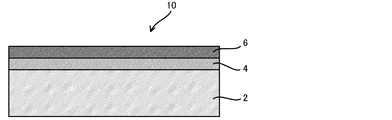
- FIG. 1 is a cross-sectional view schematically showing one embodiment of the electrode for electrolysis of the present invention.
- the electrode 10 for electrolysis of the present embodiment includes a conductive substrate 2, an intermediate layer 4 formed on the surface of the conductive substrate 2, and a catalyst formed on the surface of the intermediate layer 4. Layer 6.
- the details of the electrode for electrolysis of the present invention will be described with reference to the drawings.
- the conductive substrate 2 is a conductor for conducting electricity for electrolysis, and is a member having a function as a carrier for supporting the intermediate layer 4 and the catalyst layer 6. At least the surface (surface on which the intermediate layer 4 is formed) of the conductive substrate 2 is formed of nickel or a nickel-based alloy. That is, the entire conductive substrate 2 may be formed of nickel or a nickel base alloy, or only the surface thereof may be formed of nickel or a nickel base alloy. Specifically, the conductive substrate 2 may have a surface of a metal material such as iron, stainless steel, aluminum, titanium, or the like, on which a coating of nickel or a nickel-based alloy is formed by plating or the like.
- the thickness of the conductive substrate is preferably 0.05 to 5 mm.
- the shape of the conductive substrate is preferably a shape having an opening for removing bubbles such as oxygen and hydrogen generated.
- an expanded mesh or a porous expanded mesh can be used as the conductive substrate.
- the opening ratio of the conductive substrate is preferably 10 to 95%.
- the intermediate layer 4 is a layer formed on the surface of the conductive substrate 2.
- the intermediate layer 4 suppresses corrosion or the like of the conductive substrate 2 and stably fixes the catalyst layer 6 to the conductive substrate 2. Further, the intermediate layer 4 also serves to quickly supply current to the catalyst layer 6.
- the intermediate layer 4 is formed of a lithium-containing nickel oxide represented by a composition formula Li x Ni 2 ⁇ x O 2 (0.02 ⁇ x ⁇ 0.5). When x in the composition formula is less than 0.02, the conductivity is insufficient. On the other hand, when x exceeds 0.5, physical strength and chemical stability are lowered.
- the intermediate layer 4 formed of the lithium-containing nickel oxide represented by the above composition formula has sufficient electrical conductivity for electrolysis and exhibits excellent physical strength and chemical stability even when used for a long period of time.
- the thickness of the intermediate layer is preferably 0.01 ⁇ m or more and 100 ⁇ m or less, and more preferably 0.1 ⁇ m or more and 10 ⁇ m or less. If the thickness of the intermediate layer is less than 0.01 ⁇ m, the above-described function does not appear. On the other hand, even if the thickness of the intermediate layer exceeds 100 ⁇ m, the voltage loss due to the resistance in the intermediate layer becomes large and the above-mentioned function is hardly exhibited, and there are cases where manufacturing costs and the like are slightly disadvantageous.
- the average density of the intermediate layer is preferably not more than 5.1 g / cm 3 or more 6.67 g / cm 3, more preferably at most 5.1 g / cm 3 or more 6.0 g / cm 3, 5 particularly preferably .5g / cm 3 or more 6.0 g / cm 3 or less.
- the intermediate layer preferably has a small proportion of pores formed therein and is dense. Specifically, the porosity of the intermediate layer (the ratio value of the area of the pores (voids) in the entire intermediate layer) is preferably 0.29 or less, and more preferably 0.18 or less. preferable.
- the porosity of the intermediate layer is determined based on the image processing software attached to a commercially available CCD digital microscope (for example, trade name “MSX-500Di” manufactured by Moritex Co., Ltd.) for analyzing the cross-section photograph (SEM image) of the intermediate layer. Etc. can be calculated by analyzing the image.
- the catalyst layer 6 is a layer having catalytic ability that is formed on the surface of the intermediate layer 4. By interposing the intermediate layer 4, the catalyst layer 6 is fixed on the conductive substrate 2 with sufficient strength.
- the type of catalyst contained in the catalyst layer 6 is not particularly limited, and a catalyst having catalytic ability according to the purpose can be selected and used.
- the catalyst layer 6 can be composed of a catalyst used for the anode for alkaline water electrolysis.
- the catalyst layer 6 can be comprised with the catalyst used for the cathode for alkaline water electrolysis.
- the catalyst include nickel cobalt spinel oxide (NiCo 2 O 4 ), lanthanoid nickel cobalt perovskite oxide, iridium oxide, ruthenium oxide, and lithium nickel cobalt oxide.
- the lanthanoid nickel cobalt perovskite oxide has the structural formula XNi a Co 1-a O 3 (X is at least one metal selected from lanthanum, cerium, and praseodymium, 0 ⁇ a ⁇ 1).
- a catalyst layer may be formed using one kind, or a catalyst layer may be formed using a plurality of catalysts. When a plurality of catalysts are used, the components can be mixed to form a single catalyst layer.
- the catalyst component layers may be laminated to form a catalyst layer.
- each layer may be composed of one type of catalyst or a layer in which a plurality of catalysts are mixed.
- a layer made of iridium oxide may be laminated thereon.
- the thickness and density of the catalyst layer are not particularly limited, and may be appropriately set according to the use of the electrode.
- the method for manufacturing an electrode for electrolysis described below is a method for manufacturing the electrode for electrolysis described above, and the intermediate layer is formed by a thermal decomposition method. Note that the method of forming the intermediate layer is not limited to the thermal decomposition method, and for example, sputtering, ion plating, plasma spraying, or the like can be employed.
- the method for producing an electrode for electrolysis according to the present invention using a pyrolysis method comprises a step of applying an aqueous solution containing lithium ions and nickel ions to the surface of a conductive substrate (application step), and a conductive substrate coated with the aqueous solution.
- Intermediate layer forming step and a step of forming a catalyst layer on the surface of the formed intermediate layer (catalyst layer forming step).
- Pretreatment process Prior to performing the coating step, it is preferable to chemically etch the conductive substrate in advance in order to remove contaminant particles such as metal and organic matter on the surface.
- the consumption amount of the conductive substrate by the chemical etching treatment is preferably about 30 g / m 2 or more and 400 g / m 2 or less.
- a precursor aqueous solution containing lithium ions and nickel ions is applied to the surface of the conductive substrate.
- the intermediate layer is formed by a so-called pyrolysis method.
- an aqueous precursor solution of the intermediate layer is prepared.
- a precursor containing a lithium component known precursors such as lithium nitrate, lithium carbonate, lithium chloride, lithium hydroxide, and lithium carboxylate can be used. Examples of the lithium carboxylate include lithium formate and lithium acetate.
- a precursor containing a nickel component known precursors such as nickel nitrate, nickel carbonate, nickel chloride and nickel carboxylate can be used.
- nickel carboxylate examples include nickel formate and nickel acetate.
- lithium carboxylate and nickel carboxylate as a precursor, a dense intermediate layer can be formed even when fired at a low temperature as described later, which is particularly preferable.
- the precursor An aqueous body solution can be prepared.
- the concentration of nickel ion source such as nickel carboxylate is preferably 0.1 mol / L or more and 1 mol / L or less, preferably 0.1 mol / L or more and 0.0. More preferably, it is 6 mol / L or less.
- aqueous solution containing lithium ions and nickel ions is applied to the surface of the conductive substrate.
- a coating method a known method such as brush coating, roller coating, spin coating, electrostatic coating or the like can be used.
- the conductive substrate coated with the aqueous solution is dried.
- the drying temperature is preferably a temperature that avoids rapid solvent evaporation (eg, about 60 to 80 ° C.).
- intermediate layer forming process In the intermediate layer forming step, the conductive substrate coated with the aqueous solution is heat-treated.
- an intermediate layer made of lithium-containing nickel oxide represented by the composition formula Li x Ni 2 ⁇ x O 2 (0.02 ⁇ x ⁇ 0.5) can be formed on the surface of the conductive substrate. it can.
- the heat treatment temperature can be set as appropriate. Considering the decomposition temperature of the precursor and the production cost, the heat treatment temperature is preferably 450 ° C. or higher and 600 ° C. or lower, and more preferably 450 ° C. or higher and 550 ° C. or lower. For example, the decomposition temperature of lithium nitrate is about 430 ° C., and the decomposition temperature of nickel acetate is about 373 ° C. By setting the heat treatment temperature to 450 ° C. or higher, each component can be more reliably decomposed. When the heat treatment temperature is higher than 600 ° C., the oxidation of the conductive substrate tends to proceed, and the electrode resistance may increase to increase the voltage loss.
- the heat treatment time may be appropriately set in consideration of the reaction rate, productivity, oxidation resistance on the catalyst layer surface, and the like.
- the thickness of the intermediate layer to be formed can be controlled by appropriately setting the number of times the aqueous solution is applied in the above-described application step.
- the application and drying of the aqueous solution may be repeated for each layer, and the entire layer may be heat-treated after the top layer is formed. You may heat-process.
- the pretreatment temperature and the overall heat treatment temperature may be the same or different.
- the pretreatment time is preferably shorter than the entire heat treatment time.
- An intermediate layer made of lithium-containing nickel oxide is formed by heat-treating the conductive substrate coated with an aqueous solution. Since the intermediate layer can be formed by heat treatment at a relatively low temperature, the reaction between nickel contained in the conductive substrate and the component forming the intermediate layer can be suppressed. That is, the molar ratio of lithium and nickel in the lithium-containing nickel oxide constituting the intermediate layer is substantially the same as the molar ratio of lithium and nickel in the aqueous solution.
- a catalyst layer is formed on the surface of the intermediate layer formed in the above-described intermediate layer forming step.
- the method for forming the catalyst layer is not particularly limited, and a conventionally known technique is appropriately selected according to the type of catalyst constituting the catalyst layer.
- the catalyst layer can be formed by a method such as sputtering or arc ion plating in addition to the thermal decomposition method similar to the method for forming the intermediate layer.
- each component can be mixed to form a single catalyst layer.
- the mixed catalyst layer for example, when a thermal decomposition method is used, a coating solution in which all precursors of the respective catalysts are mixed is prepared, and this coating solution is applied on the intermediate layer and heat-treated.
- the catalyst layer can be formed by preparing coating solutions each containing a catalyst precursor constituting each layer and applying them in layers.
- the method for producing an electrode for electrolysis of the present invention preferably further includes a step of heat treatment at 450 ° C. or more and 600 ° C. or less after forming the catalyst layer.
- the heat treatment temperature can be set as appropriate. Considering the decomposition temperature of the precursor and production cost, the heat treatment temperature is preferably 450 ° C. or higher and 600 ° C. or lower, more preferably 450 ° C. or higher and 550 ° C. or lower.
- the electrode for electrolysis of the present invention can be used not only as an anode for electrolysis but also as a cathode for electrolysis. Furthermore, the electrode for electrolysis of the present invention can be used as a cathode for alkaline water electrolysis as well as an anode for alkaline water electrolysis. That is, if the electrode for electrolysis of the present invention is used, an electrolysis cell such as an alkaline water electrolysis cell can be constituted.
- constituent materials other than the anode in the case where an alkaline water electrolysis cell is configured using the electrode for electrolysis of the present invention as an anode for alkaline water electrolysis will be described.
- the cathode it is preferable to select and use a substrate made of a material that can withstand alkaline water electrolysis and a catalyst having a small cathode overvoltage.
- a nickel substrate or a nickel substrate having an active cathode coated thereon can be used.
- Examples of the shape of the cathode substrate include a plate shape, an expanded mesh, a porous expanded mesh, and the like.
- the cathode material examples include porous nickel having a large surface area and Ni—Mo based material.
- Raney nickel-based materials such as Ni—Al, Ni—Zn, Ni—Co—Zn
- sulfide-based materials such as Ni—S
- hydrogen storage alloy-based materials such as Ti 2 Ni.
- the catalyst those having properties such as low hydrogen overvoltage, high short-circuit stability, high poisoning resistance and the like are preferable.
- metals such as platinum, palladium, ruthenium, iridium, and oxides thereof are preferable.
- asbestos, non-woven fabric, ion exchange membrane, polymer porous membrane, and a composite membrane of an inorganic substance and an organic polymer can be used.
- an ion permeable membrane in which an organic fiber cloth is embedded in a mixture of a hydrophilic inorganic material such as a calcium phosphate compound or calcium fluoride and an organic binder such as polysulfone, polypropylene, and polyvinylidene fluoride. can be used.
- film-forming mixtures of particulate inorganic hydrophilic materials such as antimony and zirconium oxides and hydroxides with organic binders such as fluorocarbon polymers, polysulfones, polypropylene, polyvinyl chloride, and polyvinyl butyral film-forming mixtures of particulate inorganic hydrophilic materials such as antimony and zirconium oxides and hydroxides with organic binders such as fluorocarbon polymers, polysulfones, polypropylene, polyvinyl chloride, and polyvinyl butyral
- an ion-permeable membrane having a stretched organic fiber cloth embedded therein can be used.
- an alkaline water electrolysis cell having the electrode for electrolysis of the present invention as a constituent element a high concentration alkaline aqueous solution can be electrolyzed.
- an aqueous solution of an alkali metal hydroxide such as potassium hydroxide (KOH) or sodium hydroxide (NaOH) is preferable.
- the concentration of the alkaline aqueous solution is preferably 1.5% by mass or more and 40% by mass or less.
- the concentration of the alkaline aqueous solution is preferably 15% by mass or more and 40% by mass or less because the electric conductivity is large and the power consumption can be suppressed.
- the concentration of the alkaline aqueous solution is preferably 20% by mass or more and 30% by mass or less.
- a nickel expanded mesh (10 cm ⁇ 10 cm, LW ⁇ 3.7 SW ⁇ 0.9 ST ⁇ 0.8 T) was prepared. This expanded mesh was immersed in 17.5% by mass hydrochloric acid and subjected to chemical etching treatment in the vicinity of the boiling point for 6 minutes. The above aqueous solution was applied to the surface of the anode substrate after the chemical etching treatment with a brush, and then dried at 60 ° C. for 10 minutes. Next, heat treatment was performed at 500 ° C. for 15 minutes in an air atmosphere.
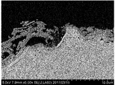
- Example 1 The process from application of the aqueous solution to heat treatment was repeated 20 times to obtain an intermediate (sample 1) in which an intermediate layer (composition: Li 0.1 Ni 1.9 O 2 ) was formed on the surface of the anode substrate.
- the thickness of the intermediate layer formed in the obtained intermediate was 3.8 ⁇ m, and the average layer density was 5.6 g / cm 3 .
- An SEM image of the intermediate cross section of Sample 1 is shown in FIG.
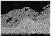
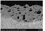
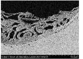
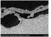
- Examples 2 to 12 An intermediate layer of Samples 2 to 12 was obtained by forming an intermediate layer in the same manner as Sample 1 except that the conditions shown in Table 1 were used. Table 2 shows the properties of the obtained intermediate layer (oxide) of each intermediate. In addition, SEM images of the cross sections of the obtained intermediates are shown in FIGS. The average layer density of the intermediate layer was calculated from Equation (1) using the porosity of the intermediate layer calculated by image analysis of a cross-sectional photograph (SEM image) of the intermediate layer. The porosity of the intermediate layer was determined from the number of pixels of the binarized SEM image using image processing software (manufactured by Moritex Corporation, image processing software attached to the product name “MSX-500Di”). It was calculated as a value of “pore area / total area”.
- the nickel acetate concentration of the aqueous solution was 0.56 mol / L.
- a nickel expanded mesh (10 cm ⁇ 10 cm, LW ⁇ 3.7 SW ⁇ 0.9 ST ⁇ 0.8 T) was prepared. This expanded mesh was blasted (0.3 MPa) with 60 mesh alumina particles, then immersed in 20% by mass hydrochloric acid, and chemically etched for 6 minutes near the boiling point. The above aqueous solution was applied to the surface of the anode substrate after the chemical etching treatment with a brush, and then dried at 80 ° C. for 15 minutes. Next, heat treatment was performed at 600 ° C. for 15 minutes in an air atmosphere.
- the process from application of the aqueous solution to heat treatment was repeated 20 times to obtain an intermediate in which an intermediate layer (composition: Li 0.5 Ni 1.5 O 2 ) was formed on the surface of the anode substrate.
- the thickness of the intermediate layer formed in the obtained intermediate was 5.1 to 8.3 ⁇ m, and the average layer density was 5.8 to 5.9 g / cm 3 .
- the obtained coating solution was applied to the surface of the intermediate layer of the above intermediate so that the amount of metal per coating was 1 g / m 2 and then dried at room temperature for 10 minutes and at 60 ° C. for 10 minutes. .
- thermal decomposition was performed by heat treatment at 350 ° C. for 15 minutes in an air circulation type electric furnace.
- the metal amount of the formed catalyst layer was 4 g / m 2 .
- Example 2 On the surface of the catalyst layer of the anode for alkaline water electrolysis obtained in Example 1, a hexaammineiridium solution was applied so that the amount of metal (Ir) per application was 1 g / m 2 . Thereafter, thermal decomposition was performed by heat treatment at 350 ° C. for 15 minutes in an air circulation type electric furnace. The process from application of the hexaammineiridium solution to thermal decomposition was repeated 4 times, and the first catalyst layer (composition: NiCo 2 O 4 ) and the second catalyst layer (composition: IrO 2 ) were formed on the surface of the intermediate layer. An anode for alkaline water electrolysis having a layered catalyst layer formed in this order was obtained. The amount of metal in the formed second catalyst layer was 4 g / m 2 .
- Example 3 On the surface of the catalyst layer of the anode for alkaline water electrolysis obtained in Example 1, the iridium hydroxyacetochloride complex (hereinafter referred to as “the amount of metal (Ir) per application” is 1.25 g / m 2.
- the solution (denoted “IrHAC”) was applied. Thereafter, thermal decomposition was performed by heat treatment at 350 ° C. for 15 minutes in an air circulation type electric furnace. The treatment from application of IrHAC solution to thermal decomposition was repeated four times, and the first catalyst layer (composition: NiCo 2 O 4 ) and the second catalyst layer (composition: IrO 2 ) were in this order on the surface of the intermediate layer.
- a formed catalyst layer having a laminated structure was provided. The metal amount of the formed second catalyst layer was 5 g / m 2 . Then, it heat-processed for 60 minutes at 540 degreeC in the air circulation type electric furnace, and obtained the anode for alkaline water electrolysis.
- the obtained coating solution was applied to the surface of the anode substrate after the chemical etching treatment produced in Example 1 so that the amount of metal per coating was 1 g / m 2, and then at room temperature for 10 minutes and 60 minutes. Dry at 10 ° C. for 10 minutes. Next, thermal decomposition was performed by heat treatment at 350 ° C. for 15 minutes in an air circulation type electric furnace.
- the treatment from application of the coating solution to thermal decomposition was repeated four times to obtain an alkaline water electrolysis anode in which a catalyst layer (composition: NiCo 2 O 4 ) was directly formed on the surface of the anode substrate.
- the metal amount of the formed catalyst layer was 4 g / m 2 .
- FIG. 15 shows the current density at a voltage of 1.6V.
- the alkaline water electrolysis anode of Example 1 has an initial activity and an activity after the lapse of the number of cycles compared to the alkaline water electrolysis anode of Comparative Example 1 and the nickel plate of Comparative Example 2. It is clear that the difference is small and the activity is less likely to decrease over time.
- the electrode for electrolysis of the present invention is suitable, for example, as an anode for alkaline water electrolysis that constitutes electrolysis equipment or the like that uses power with large output fluctuations such as renewable energy as a power source.
Abstract
Description
[1]少なくともその表面がニッケル又はニッケル基合金からなる導電性基体と、前記導電性基体の表面上に形成された、組成式LixNi2-xO2(0.02≦x≦0.5)で表されるリチウム含有ニッケル酸化物からなる中間層と、前記中間層の表面上に形成された触媒層と、を備える電解用電極。
[2]前記中間層の層平均密度が、5.1g/cm3以上6.67g/cm3以下である前記[1]に記載の電解用電極。
[3]前記触媒層が、ニッケルコバルトスピネル酸化物、ランタノイドニッケルコバルトペロブスカイト酸化物、イリジウム酸化物、ルテニウム酸化物、及びリチウムニッケルコバルト酸化物からなる群より選択される少なくとも一種の触媒を含む前記[1]又は[2]に記載の電解用電極。 That is, according to the present invention, the following electrode for electrolysis is provided.
[1] A conductive substrate having at least a surface thereof made of nickel or a nickel-based alloy, and a composition formula Li x Ni 2-x O 2 (0.02 ≦ x ≦ 0. An electrode for electrolysis comprising: an intermediate layer made of lithium-containing nickel oxide represented by 5); and a catalyst layer formed on the surface of the intermediate layer.
[2] The layers average density of the intermediate layer, the electrolytic electrode according to 5.1 g / cm 3 or more 6.67 g / cm 3 or less is the [1].
[3] The catalyst layer includes at least one catalyst selected from the group consisting of nickel cobalt spinel oxide, lanthanoid nickel cobalt perovskite oxide, iridium oxide, ruthenium oxide, and lithium nickel cobalt oxide. The electrode for electrolysis according to [1] or [2].
[4]前記[1]~[3]のいずれかに記載の電解用電極の製造方法であって、少なくともその表面がニッケル又はニッケル基合金からなる導電性基体の表面に、リチウムイオン及びニッケルイオンを含有する水溶液を塗布する工程と、前記水溶液を塗布した前記導電性基体を熱処理して、前記導電性基材の表面上に組成式LixNi2-xO2(0.02≦x≦0.5)で表されるリチウム含有ニッケル酸化物からなる中間層を形成する工程と、形成された前記中間層の表面上に触媒層を形成する工程と、を含む電解用電極の製造方法。
[5]カルボン酸ニッケル及びカルボン酸リチウムの少なくとも一方を水に溶解させて前記水溶液を調製する前記[4]に記載の電解用電極の製造方法。
[6]前記触媒層を形成した後に450℃以上600℃以下で熱処理する工程をさらに含む前記[4]又は[5]に記載の電解用電極の製造方法。 Moreover, according to this invention, the manufacturing method of the electrode for electrolysis shown below is provided.
[4] The method for producing an electrode for electrolysis according to any one of the above [1] to [3], wherein at least the surface has lithium ions and nickel ions on the surface of a conductive substrate made of nickel or a nickel-based alloy. Coating the aqueous solution containing the aqueous solution, and heat-treating the conductive substrate coated with the aqueous solution to form a composition formula Li x Ni 2-x O 2 (0.02 ≦ x ≦ on the surface of the conductive substrate). A method for producing an electrode for electrolysis, comprising: a step of forming an intermediate layer made of lithium-containing nickel oxide represented by 0.5); and a step of forming a catalyst layer on the surface of the formed intermediate layer.
[5] The method for producing an electrode for electrolysis according to [4], wherein the aqueous solution is prepared by dissolving at least one of nickel carboxylate and lithium carboxylate in water.
[6] The method for producing an electrode for electrolysis according to [4] or [5], further including a step of heat-treating at 450 ° C. or more and 600 ° C. or less after forming the catalyst layer.
図1は、本発明の電解用電極の一実施形態を模式的に示す断面図である。図1に示すように、本実施形態の電解用電極10は、導電性基体2と、導電性基体2の表面上に形成された中間層4と、中間層4の表面上に形成された触媒層6とを備える。以下、本発明の電解用電極の詳細につき、図面を参照しつつ説明する。 <Electrode for electrolysis>
FIG. 1 is a cross-sectional view schematically showing one embodiment of the electrode for electrolysis of the present invention. As shown in FIG. 1, the
導電性基体2は、電気分解のための電気を通すための導電体であり、中間層4及び触媒層6を担持する担体としての機能を有する部材である。導電性基体2の少なくとも表面(中間層4が形成される面)は、ニッケル又はニッケル基合金で形成されている。すなわち、導電性基体2は、全体がニッケル又はニッケル基合金で形成されていてもよく、表面のみがニッケル又はニッケル基合金で形成されていてもよい。具体的に、導電性基体2は、鉄、ステンレス、アルミニウム、チタン等の金属材料の表面に、めっき等によりニッケル又はニッケル基合金のコーティングが形成されたものであってもよい。 (Conductive substrate)
The
中間層4は、導電性基体2の表面上に形成される層である。中間層4は、導電性基体2の腐食等を抑制するとともに、触媒層6を導電性基体2に安定的に固着させる。また、中間層4は、触媒層6に電流を速やかに供給する役割も果たす。中間層4は、組成式LixNi2-xO2(0.02≦x≦0.5)で表されるリチウム含有ニッケル酸化物で形成されている。上記組成式中のxが0.02未満であると、導電性が不十分になる。一方、xが0.5を超えると物理的強度及び化学的安定性が低下する。上記組成式で表されるリチウム含有ニッケル酸化物で形成された中間層4は、電解に十分な導電性を有するとともに、長期間使用した場合でも優れた物理的強度及び化学的安定性を示す。 (Middle layer)
The
層平均密度(g/cm3)=6.67×(1-気孔率) ・・・(1) The layer average density (apparent density D) of the intermediate layer formed on the surface of the conductive substrate can be measured and calculated according to the following procedure. First, a cross-sectional photograph (SEM image) of the intermediate layer is subjected to image analysis, and the porosity of the intermediate layer is calculated. Here, the true density of the lithium-containing nickel oxide (LiNiO) is 6.67 g / cm 3 . For this reason, a layer average density (apparent density D) is computable from following formula (1).
Layer average density (g / cm 3 ) = 6.67 × (1−porosity) (1)
触媒層6は、中間層4の表面上に形成される触媒能を有する層である。中間層4を介在させることで、触媒層6は導電性基体2上に十分な強度で固定されている。触媒層6に含まれる触媒の種類は特に限定されず、目的に応じた触媒能を有する触媒を選択して用いることができる。例えば、電解用電極10がアルカリ水電解用陽極である場合には、アルカリ水電解用陽極に用いる触媒で触媒層6を構成することができる。また、電解用電極10がアルカリ水電解用陰極である場合には、アルカリ水電解用陰極に用いる触媒で触媒層6を構成することができる。 (Catalyst layer)
The catalyst layer 6 is a layer having catalytic ability that is formed on the surface of the
次に、本発明の電解用電極の製造方法について説明する。以下で説明する電解用電極の製造方法は、前述の電解用電極を製造する方法であり、中間層を熱分解法により形成する。なお、中間層を形成する方法は熱分解法に限定されず、例えばスパッタリングやイオンプレーティング、プラズマ溶射なども採用することができる。 <Method for producing electrode for electrolysis>
Next, the manufacturing method of the electrode for electrolysis of this invention is demonstrated. The method for manufacturing an electrode for electrolysis described below is a method for manufacturing the electrode for electrolysis described above, and the intermediate layer is formed by a thermal decomposition method. Note that the method of forming the intermediate layer is not limited to the thermal decomposition method, and for example, sputtering, ion plating, plasma spraying, or the like can be employed.
塗布工程を行う前に、表面の金属や有機物などの汚染粒子を除去するために、導電性基体を予め化学エッチング処理することが好ましい。化学エッチング処理による導電性基体の消耗量は、30g/m2以上400g/m2以下程度とすることが好ましい。また、中間層との密着力を高めるために、導電性基体の表面を予め粗面化処理することが好ましい。粗面化処理としては、粉末を吹き付けるブラスト処理;基体可溶性の酸を用いたエッチング処理;プラズマ溶射などがある。 (Pretreatment process)
Prior to performing the coating step, it is preferable to chemically etch the conductive substrate in advance in order to remove contaminant particles such as metal and organic matter on the surface. The consumption amount of the conductive substrate by the chemical etching treatment is preferably about 30 g / m 2 or more and 400 g / m 2 or less. In order to increase the adhesion with the intermediate layer, it is preferable to roughen the surface of the conductive substrate in advance. Examples of the surface roughening treatment include blast treatment for spraying powder; etching treatment using a substrate-soluble acid; plasma spraying and the like.
塗布工程では、リチウムイオン及びニッケルイオンを含有する前駆体水溶液を導電性基体の表面に塗布する。中間層は、いわゆる熱分解法によって形成される。熱分解法により中間層を形成するに際しては、まず、中間層の前駆体水溶液を調製する。リチウム成分を含む前駆体としては、硝酸リチウム、炭酸リチウム、塩化リチウム、水酸化リチウム、カルボン酸リチウムなど公知の前駆体を使用することができる。カルボン酸リチウムとしては、ギ酸リチウムや酢酸リチウムを挙げることができる。ニッケル成分を含む前駆体としては、硝酸ニッケル、炭酸ニッケル、塩化ニッケル、カルボン酸ニッケルなど公知の前駆体を使用することができる。カルボン酸ニッケルとしては、ギ酸ニッケルや酢酸ニッケルを挙げることができる。特に、カルボン酸リチウム及びカルボン酸ニッケルの少なくとも一方を前駆体として用いることにより、後述するように低温で焼成した場合であっても緻密な中間層を形成することができるので特に好ましい。 (Coating process)
In the coating step, a precursor aqueous solution containing lithium ions and nickel ions is applied to the surface of the conductive substrate. The intermediate layer is formed by a so-called pyrolysis method. In forming the intermediate layer by the thermal decomposition method, first, an aqueous precursor solution of the intermediate layer is prepared. As a precursor containing a lithium component, known precursors such as lithium nitrate, lithium carbonate, lithium chloride, lithium hydroxide, and lithium carboxylate can be used. Examples of the lithium carboxylate include lithium formate and lithium acetate. As a precursor containing a nickel component, known precursors such as nickel nitrate, nickel carbonate, nickel chloride and nickel carboxylate can be used. Examples of nickel carboxylate include nickel formate and nickel acetate. In particular, by using at least one of lithium carboxylate and nickel carboxylate as a precursor, a dense intermediate layer can be formed even when fired at a low temperature as described later, which is particularly preferable.
中間層形成工程では、水溶液を塗布した導電性基体を熱処理する。これにより、組成式LixNi2-xO2(0.02≦x≦0.5)で表されるリチウム含有ニッケル酸化物からなる中間層を導電性基材の表面上に形成することができる。 (Intermediate layer forming process)
In the intermediate layer forming step, the conductive substrate coated with the aqueous solution is heat-treated. Thus, an intermediate layer made of lithium-containing nickel oxide represented by the composition formula Li x Ni 2−x O 2 (0.02 ≦ x ≦ 0.5) can be formed on the surface of the conductive substrate. it can.
触媒層形成工程では、前述の中間層形成工程で形成された中間層の表面上に触媒層を形成する。触媒層を形成する方法は、触媒層を構成する触媒の種類に応じて従来公知の技術が適宜選択され、特に限定されない。例えば、上記の中間層を形成する方法と同様の熱分解法の他、スパッタリングやアークイオンプレーティング等の方法によっても触媒層を形成することができる。上述したように、複数の触媒を用いて触媒層を形成する場合には、各成分を混合して1層の触媒層を形成することができる。混合触媒層を形成するにあたっては、例えば熱分解法を用いる場合、各触媒の前駆体をすべて混合した塗布液を調製して、中間層上にこの塗布液を塗布して熱処理する。また、各層を構成する触媒の前駆体を含む塗布液をそれぞれ準備し、これらを重ねて塗布することによって触媒層を形成することもできる。 (Catalyst layer formation process)
In the catalyst layer forming step, a catalyst layer is formed on the surface of the intermediate layer formed in the above-described intermediate layer forming step. The method for forming the catalyst layer is not particularly limited, and a conventionally known technique is appropriately selected according to the type of catalyst constituting the catalyst layer. For example, the catalyst layer can be formed by a method such as sputtering or arc ion plating in addition to the thermal decomposition method similar to the method for forming the intermediate layer. As described above, when a catalyst layer is formed using a plurality of catalysts, each component can be mixed to form a single catalyst layer. In forming the mixed catalyst layer, for example, when a thermal decomposition method is used, a coating solution in which all precursors of the respective catalysts are mixed is prepared, and this coating solution is applied on the intermediate layer and heat-treated. Alternatively, the catalyst layer can be formed by preparing coating solutions each containing a catalyst precursor constituting each layer and applying them in layers.
本発明の電解用電極の製造方法は、触媒層を形成した後に450℃以上600℃以下で熱処理する工程をさらに含むことが好ましい。触媒層の形成後に熱処理することで、電解性能の劣化がさらに抑制されるといった効果を得ることが期待される。熱処理温度は適宜設定することができる。前駆体の分解温度や生産コストなどを考慮すると、熱処理温度は450℃以上600℃以下とすることが好ましく、450℃以上550℃以下とすることがさらに好ましい。 (Heat treatment process)
The method for producing an electrode for electrolysis of the present invention preferably further includes a step of heat treatment at 450 ° C. or more and 600 ° C. or less after forming the catalyst layer. By heat-treating after the formation of the catalyst layer, it is expected to obtain an effect that the degradation of electrolytic performance is further suppressed. The heat treatment temperature can be set as appropriate. Considering the decomposition temperature of the precursor and production cost, the heat treatment temperature is preferably 450 ° C. or higher and 600 ° C. or lower, more preferably 450 ° C. or higher and 550 ° C. or lower.
本発明の電解用電極は、例えば、電解用の陽極だけでなく、電解用の陰極としても用いることができる。さらに、本発明の電解用電極は、アルカリ水電解用陽極の他、アルカリ水電解用陰極としても用いることができる。すなわち、本発明の電解用電極を用いれば、アルカリ水電解セル等の電解セルを構成することができる。以下、本発明の電解用電極をアルカリ水電解用陽極として用いてアルカリ水電解セルを構成する場合における、陽極以外の構成材料について説明する。 <Electrolysis cell>
The electrode for electrolysis of the present invention can be used not only as an anode for electrolysis but also as a cathode for electrolysis. Furthermore, the electrode for electrolysis of the present invention can be used as a cathode for alkaline water electrolysis as well as an anode for alkaline water electrolysis. That is, if the electrode for electrolysis of the present invention is used, an electrolysis cell such as an alkaline water electrolysis cell can be constituted. Hereinafter, constituent materials other than the anode in the case where an alkaline water electrolysis cell is configured using the electrode for electrolysis of the present invention as an anode for alkaline water electrolysis will be described.
その他、Ni-Al、Ni-Zn、Ni-Co-Znなどのラネーニッケル系材料;Ni-Sなどの硫化物系材料;Ti2Niなど水素吸蔵合金系材料などがある。触媒としては、水素過電圧が低い、短絡安定性が高い、被毒耐性が高い等の性質を有するものが好ましい。その他の触媒としては、白金、パラジウム、ルテニウム、イリジウムなどの金属、及びこれらの酸化物が好ましい。 Examples of the cathode material include porous nickel having a large surface area and Ni—Mo based material.
In addition, there are Raney nickel-based materials such as Ni—Al, Ni—Zn, Ni—Co—Zn; sulfide-based materials such as Ni—S; and hydrogen storage alloy-based materials such as Ti 2 Ni. As the catalyst, those having properties such as low hydrogen overvoltage, high short-circuit stability, high poisoning resistance and the like are preferable. As other catalysts, metals such as platinum, palladium, ruthenium, iridium, and oxides thereof are preferable.
(試料1)
硝酸リチウム(純度99%)及び酢酸ニッケル四水和物(Ni(CH3COO)2・4H2O、純度98.0%)を純水に溶解させて、リチウム(Li)とニッケル(Ni)のモル比がLi:Ni=0.1:1.9である水溶液を得た。水溶液の酢酸ニッケル濃度は0.56mol/Lとした。 <Formation of intermediate layer (production of intermediate)>
(Sample 1)
Lithium nitrate (purity 99%) and nickel acetate tetrahydrate (Ni (CH 3 COO) 2 .4H 2 O, purity 98.0%) are dissolved in pure water, and lithium (Li) and nickel (Ni) are dissolved. An aqueous solution having a molar ratio of Li: Ni = 0.1: 1.9 was obtained. The nickel acetate concentration of the aqueous solution was 0.56 mol / L.
表1に示す条件としたこと以外は、前述の試料1と同様にして中間層を形成して、試料2~12の中間体を得た。得られた各中間体の中間層(酸化物)の特性を表2に示す。また、得られた各中間体断面のSEM画像を図3~13に示す。中間層の層平均密度は、中間層の断面写真(SEM画像)を画像解析して算出した中間層の気孔率を用いて、式(1)から算出した。なお、中間層の気孔率は、画像処理ソフト(モリテックス社製、商品名「MSX-500Di」に付属する画像処理ソフト)を使用し、二値化したSEM画像のピクセル数から、「気孔率=気孔面積/総面積」の値として算出した。 <
An intermediate layer of


(実施例1)
硝酸リチウム及び酢酸ニッケル四水和物を純水に溶解させて、リチウム(Li)とニッケル(Ni)のモル比がLi:Ni=0.5:1.5である水溶液を得た。水溶液の酢酸ニッケル濃度は0.56mol/Lとした。 <Manufacture of anode for alkaline water electrolysis>
Example 1
Lithium nitrate and nickel acetate tetrahydrate were dissolved in pure water to obtain an aqueous solution in which the molar ratio of lithium (Li) to nickel (Ni) was Li: Ni = 0.5: 1.5. The nickel acetate concentration of the aqueous solution was 0.56 mol / L.
実施例1で得たアルカリ水電解用陽極の触媒層の表面上に、塗布1回当たりのメタル(Ir)量が1g/m2となるように、ヘキサアンミンイリジウム溶液を塗布した。その後、空気循環式の電気炉中、350℃で15分間熱処理する熱分解を行った。ヘキサアンミンイリジウム溶液の塗布から熱分解までの処理を4回繰り返して、中間層の表面上に第1の触媒層(組成:NiCo2O4)及び第2の触媒層(組成:IrO2)がこの順に形成された積層構造の触媒層を有するアルカリ水電解用陽極を得た。形成された第2の触媒層のメタル量は4g/m2であった。 (Example 2)
On the surface of the catalyst layer of the anode for alkaline water electrolysis obtained in Example 1, a hexaammineiridium solution was applied so that the amount of metal (Ir) per application was 1 g / m 2 . Thereafter, thermal decomposition was performed by heat treatment at 350 ° C. for 15 minutes in an air circulation type electric furnace. The process from application of the hexaammineiridium solution to thermal decomposition was repeated 4 times, and the first catalyst layer (composition: NiCo 2 O 4 ) and the second catalyst layer (composition: IrO 2 ) were formed on the surface of the intermediate layer. An anode for alkaline water electrolysis having a layered catalyst layer formed in this order was obtained. The amount of metal in the formed second catalyst layer was 4 g / m 2 .
実施例1で得たアルカリ水電解用陽極の触媒層の表面上に、塗布1回当たりのメタル(Ir)量が1.25g/m2となるように、イリジウムヒドロキシアセトクロリド錯体(以下、「IrHAC」と記す)溶液を塗布した。その後、空気循環式の電気炉中、350℃で15分間熱処理する熱分解を行った。IrHAC溶液の塗布から熱分解までの処理を4回繰り返して、中間層の表面上に第1の触媒層(組成:NiCo2O4)及び第2の触媒層(組成:IrO2)がこの順に形成された積層構造の触媒層を設けた。形成された第2の触媒層のメタル量は5g/m2であった。その後、空気循環式の電気炉中、540℃で60分間熱処理して、アルカリ水電解用陽極を得た。 (Example 3)
On the surface of the catalyst layer of the anode for alkaline water electrolysis obtained in Example 1, the iridium hydroxyacetochloride complex (hereinafter referred to as “the amount of metal (Ir) per application” is 1.25 g / m 2. The solution (denoted “IrHAC”) was applied. Thereafter, thermal decomposition was performed by heat treatment at 350 ° C. for 15 minutes in an air circulation type electric furnace. The treatment from application of IrHAC solution to thermal decomposition was repeated four times, and the first catalyst layer (composition: NiCo 2 O 4 ) and the second catalyst layer (composition: IrO 2 ) were in this order on the surface of the intermediate layer. A formed catalyst layer having a laminated structure was provided. The metal amount of the formed second catalyst layer was 5 g / m 2 . Then, it heat-processed for 60 minutes at 540 degreeC in the air circulation type electric furnace, and obtained the anode for alkaline water electrolysis.
硝酸ニッケル及び硝酸コバルトを純水に溶解させて、ニッケル(Ni):コバルト(Co)のモル比がNi:Co=33.3:66.7である塗布液を得た。得られた塗布液を、塗布1回当たりのメタル量が1g/m2となるように、実施例1で作製した化学エッチング処理後の陽極基体の表面に塗布した後、室温で10分間及び60℃で10分間乾燥させた。次いで、空気循環式の電気炉中、350℃で15分間熱処理する熱分解を行った。塗布液の塗布から熱分解までの処理を4回繰り返して、陽極基体の表面上に触媒層(組成:NiCo2O4)が直に形成されたアルカリ水電解用陽極を得た。形成された触媒層のメタル量は4g/m2であった。 (Comparative Example 1)
Nickel nitrate and cobalt nitrate were dissolved in pure water to obtain a coating solution having a nickel (Ni): cobalt (Co) molar ratio of Ni: Co = 33.3: 66.7. The obtained coating solution was applied to the surface of the anode substrate after the chemical etching treatment produced in Example 1 so that the amount of metal per coating was 1 g / m 2, and then at room temperature for 10 minutes and 60 minutes. Dry at 10 ° C. for 10 minutes. Next, thermal decomposition was performed by heat treatment at 350 ° C. for 15 minutes in an air circulation type electric furnace. The treatment from application of the coating solution to thermal decomposition was repeated four times to obtain an alkaline water electrolysis anode in which a catalyst layer (composition: NiCo 2 O 4 ) was directly formed on the surface of the anode substrate. The metal amount of the formed catalyst layer was 4 g / m 2 .
(シャットダウン試験)
製造した各アルカリ水電解用陽極をアノードとして用いるとともに、隔膜、及びカソードを用いて小型のゼロギャップ型電解セルを作製した。電極面積は19cm2とした。25質量%KOH水溶液を電解液とし、80℃に加温して、電流密度4kA/m2(比較例1)、6kA/m2(実施例1)、10kA/m2(実施例2)、及び10kA/m2(実施例3)でそれぞれ6時間電解した。次いで、アノードとカソードを短絡状態(0kA/m2)とし、温度を下げて15時間停止させた。上記の電解から停止までの操作を1サイクルとするシャットダウン試験を行った。シャットダウン回数とセル電圧との関係を示すグラフを図14に示す。 <Evaluation>
(Shutdown test)
Each of the produced anodes for alkaline water electrolysis was used as an anode, and a small zero gap type electrolysis cell was produced using a diaphragm and a cathode. The electrode area was 19 cm 2 . 25 wt% KOH aqueous solution and electrolyte solution, warmed to 80 ° C., a current density of 4 kA / m 2 (Comparative Example 1), 6 kA / m 2 (Example 1), 10 kA / m 2 (Example 2), And 10 kA / m 2 (Example 3), respectively, and electrolysis was performed for 6 hours. Subsequently, the anode and the cathode were short-circuited (0 kA / m 2 ), and the temperature was lowered and stopped for 15 hours. A shutdown test was performed in which the operation from the electrolysis to the stop was one cycle. A graph showing the relationship between the number of shutdowns and the cell voltage is shown in FIG.
実施例1(n=1)及び比較例1のアルカリ水電解用陽極、並びにニッケル板(比較例2;面積1.0cm2、中間層及び触媒層なし)を試験サンプルとし、以下の手順にしたがって加速寿命試験を行った。まず、加速寿命試験前の各試験サンプルにつき、以下に示す条件でSSV(Slow Scan Voltammetry)を行った。SSVの結果から、各試験サンプルの酸素発生時の電圧及び電流密度を算出した。
電解液:25質量%KOH水溶液、温度30℃±1℃
電位範囲:0.5~1.8V
走査速度:5mV/sec
対極:Niコイル
参照極:可逆水素電極(RHE)
測定雰囲気:窒素雰囲気
サイクル数:5回 (Accelerated life test)
The anode for alkaline water electrolysis of Example 1 (n = 1) and Comparative Example 1 and a nickel plate (Comparative Example 2; area 1.0 cm 2 , no intermediate layer and no catalyst layer) were used as test samples, and the following procedure was followed. An accelerated life test was conducted. First, SSV (Slow Scan Voltammetry) was performed on each test sample before the accelerated life test under the following conditions. From the SSV results, the voltage and current density at the time of oxygen generation for each test sample were calculated.
Electrolyte: 25 mass% KOH aqueous solution,
Potential range: 0.5 to 1.8V
Scanning speed: 5mV / sec
Counter electrode: Ni coil Reference electrode: Reversible hydrogen electrode (RHE)
Measurement atmosphere: nitrogen atmosphere Number of cycles: 5 times
電位範囲:0.5~1.8V
操作速度:1V/sec
サイクル数:0、1,000、3,000、5,000、10,000、15,000、20,000サイクル Next, CV (Cyclic Voltammetry) was performed in the same electrolytic solution under the following conditions. Furthermore, SSV was performed on the said conditions after completion | finish of each cycle. The graph which shows the current density change of each test sample by an accelerated life test is shown in FIG. FIG. 15 shows the current density at a voltage of 1.6V.
Potential range: 0.5 to 1.8V
Operation speed: 1V / sec
Number of cycles: 0, 1,000, 3,000, 5,000, 10,000, 15,000, 20,000 cycles
4:中間層
6:触媒層
10:電解用電極 2: Conductive substrate 4: Intermediate layer 6: Catalyst layer 10: Electrode for electrolysis
Claims (6)
- 少なくともその表面がニッケル又はニッケル基合金からなる導電性基体と、
前記導電性基体の表面上に形成された、組成式LixNi2-xO2(0.02≦x≦0.5)で表されるリチウム含有ニッケル酸化物からなる中間層と、
前記中間層の表面上に形成された触媒層と、
を備える電解用電極。 A conductive substrate having at least a surface thereof made of nickel or a nickel-based alloy;
An intermediate layer made of lithium-containing nickel oxide represented by the composition formula Li x Ni 2-x O 2 (0.02 ≦ x ≦ 0.5), formed on the surface of the conductive substrate;
A catalyst layer formed on the surface of the intermediate layer;
An electrode for electrolysis comprising: - 前記中間層の層平均密度が、5.1g/cm3以上6.67g/cm3以下である請求項1に記載の電解用電極。 Said layer having an average density of the intermediate layer, 5.1 g / cm 3 or more 6.67 g / cm 3 or less electrode for electrolysis according to claim 1.
- 前記触媒層が、ニッケルコバルトスピネル酸化物、ランタノイドニッケルコバルトペロブスカイト酸化物、イリジウム酸化物、ルテニウム酸化物、及びリチウムニッケルコバルト酸化物からなる群より選択される少なくとも一種の触媒を含む請求項1又は2に記載の電解用電極。 The catalyst layer includes at least one catalyst selected from the group consisting of nickel cobalt spinel oxide, lanthanoid nickel cobalt perovskite oxide, iridium oxide, ruthenium oxide, and lithium nickel cobalt oxide. The electrode for electrolysis as described in 2.
- 請求項1~3のいずれか一項に記載の電解用電極の製造方法であって、
少なくともその表面がニッケル又はニッケル基合金からなる導電性基体の表面に、リチウムイオン及びニッケルイオンを含有する水溶液を塗布する工程と、
前記水溶液を塗布した前記導電性基体を熱処理して、前記導電性基材の表面上に組成式LixNi2-xO2(0.02≦x≦0.5)で表されるリチウム含有ニッケル酸化物からなる中間層を形成する工程と、
形成された前記中間層の表面上に触媒層を形成する工程と、
を含む電解用電極の製造方法。 A method for producing an electrode for electrolysis according to any one of claims 1 to 3,
Applying an aqueous solution containing lithium ions and nickel ions to the surface of a conductive substrate having at least a surface thereof made of nickel or a nickel-based alloy; and
The conductive substrate coated with the aqueous solution is heat-treated, and the lithium-containing material represented by the composition formula Li x Ni 2-x O 2 (0.02 ≦ x ≦ 0.5) is formed on the surface of the conductive substrate. Forming an intermediate layer made of nickel oxide;
Forming a catalyst layer on the surface of the formed intermediate layer;
The manufacturing method of the electrode for electrolysis containing this. - カルボン酸ニッケル及びカルボン酸リチウムの少なくとも一方を水に溶解させて前記水溶液を調製する請求項4に記載の電解用電極の製造方法。 The method for producing an electrode for electrolysis according to claim 4, wherein the aqueous solution is prepared by dissolving at least one of nickel carboxylate and lithium carboxylate in water.
- 前記触媒層を形成した後に450℃以上600℃以下で熱処理する工程をさらに含む請求項4又は5に記載の電解用電極の製造方法。 The method for producing an electrode for electrolysis according to claim 4 or 5, further comprising a step of heat-treating at 450 ° C or higher and 600 ° C or lower after forming the catalyst layer.
Priority Applications (8)
| Application Number | Priority Date | Filing Date | Title |
|---|---|---|---|
| US16/975,868 US11866834B2 (en) | 2018-03-07 | 2019-03-04 | Electrolysis electrode and method for manufacturing same |
| JP2020505004A JP7273024B2 (en) | 2018-03-07 | 2019-03-04 | Electrode for electrolysis and method for manufacturing the same |
| ES19763900T ES2934123T3 (en) | 2018-03-07 | 2019-03-04 | Electrolysis electrode and method for the manufacture thereof |
| EP19763900.8A EP3763849B1 (en) | 2018-03-07 | 2019-03-04 | Electrolysis electrode and method for manufacturing same |
| CN201980017425.4A CN111868308B (en) | 2018-03-07 | 2019-03-04 | Electrode for electrolysis and method for producing same |
| DK19763900.8T DK3763849T3 (en) | 2018-03-07 | 2019-03-04 | Electrolysis electrode and method of manufacturing the same |
| KR1020207028348A KR102232627B1 (en) | 2018-03-07 | 2019-03-04 | Electrolytic electrode and its manufacturing method |
| CA3093203A CA3093203C (en) | 2018-03-07 | 2019-03-04 | Electrolysis electrode and method for manufacturing same |
Applications Claiming Priority (2)
| Application Number | Priority Date | Filing Date | Title |
|---|---|---|---|
| JP2018-040569 | 2018-03-07 | ||
| JP2018040569 | 2018-03-07 |
Publications (1)
| Publication Number | Publication Date |
|---|---|
| WO2019172160A1 true WO2019172160A1 (en) | 2019-09-12 |
Family
ID=67846263
Family Applications (1)
| Application Number | Title | Priority Date | Filing Date |
|---|---|---|---|
| PCT/JP2019/008289 WO2019172160A1 (en) | 2018-03-07 | 2019-03-04 | Electrolysis electrode and method for manufacturing same |
Country Status (9)
| Country | Link |
|---|---|
| US (1) | US11866834B2 (en) |
| EP (1) | EP3763849B1 (en) |
| JP (1) | JP7273024B2 (en) |
| KR (1) | KR102232627B1 (en) |
| CN (1) | CN111868308B (en) |
| CA (1) | CA3093203C (en) |
| DK (1) | DK3763849T3 (en) |
| ES (1) | ES2934123T3 (en) |
| WO (1) | WO2019172160A1 (en) |
Cited By (11)
| Publication number | Priority date | Publication date | Assignee | Title |
|---|---|---|---|---|
| JP2020012171A (en) * | 2018-07-19 | 2020-01-23 | 時空化学株式会社 | Manufacturing method of electrode, electrode, and manufacturing method of hydrogen |
| WO2021182385A1 (en) * | 2020-03-09 | 2021-09-16 | デノラ・ペルメレック株式会社 | Alkaline water electrolysis method, and anode for alkaline water electrolysis |
| JP6975297B1 (en) * | 2020-08-28 | 2021-12-01 | デノラ・ペルメレック株式会社 | Anode for alkaline water electrolysis |
| WO2021251341A1 (en) * | 2020-06-11 | 2021-12-16 | 国立大学法人山梨大学 | Electrode catalyst, and anion exchange membrane electrochemical cell |
| WO2022025208A1 (en) * | 2020-07-30 | 2022-02-03 | 国立大学法人京都大学 | Anode for alkaline water electrolysis and method for producing same |
| IT202000020587A1 (en) * | 2020-08-28 | 2022-02-28 | Industrie De Nora Spa | ELECTRODE WITH ENHANCED SHUTDOWN TOLERANCE |
| JPWO2022080465A1 (en) * | 2020-10-15 | 2022-04-21 | ||
| WO2022181512A1 (en) * | 2021-02-24 | 2022-09-01 | デノラ・ペルメレック株式会社 | Anode for alkaline water electrolysis |
| KR20230062677A (en) * | 2020-10-15 | 2023-05-09 | 고쿠리츠 다이가쿠 호진 교토 다이가쿠 | Anode for alkaline water electrolysis and manufacturing method thereof |
| WO2023189350A1 (en) * | 2022-03-31 | 2023-10-05 | デノラ・ペルメレック株式会社 | Electrolysis electrode and method for producing same |
| US11866834B2 (en) | 2018-03-07 | 2024-01-09 | De Nora Permelec Ltd | Electrolysis electrode and method for manufacturing same |
Families Citing this family (1)
| Publication number | Priority date | Publication date | Assignee | Title |
|---|---|---|---|---|
| IT202100011936A1 (en) * | 2021-05-10 | 2022-11-10 | Industrie De Nora Spa | ELECTRODE FOR GAS EVOLUTION IN ELECTROLYTIC PROCESSES |
Citations (6)
| Publication number | Priority date | Publication date | Assignee | Title |
|---|---|---|---|---|
| US2928783A (en) | 1956-08-23 | 1960-03-15 | Era Patents Ltd | Porous nickel electrode |
| GB864457A (en) | 1956-08-23 | 1961-04-06 | Era Patents Ltd | Improvements relating to hydrogen-oxygen cells particularly for use as electrolysers |
| JPH08106902A (en) * | 1994-10-03 | 1996-04-23 | Murata Mfg Co Ltd | Thin film electrode for battery and its manufacture |
| JP2015086420A (en) | 2013-10-29 | 2015-05-07 | 国立大学法人横浜国立大学 | Anode for alkali water electrolysis |
| JP2017190476A (en) | 2016-04-12 | 2017-10-19 | デノラ・ペルメレック株式会社 | Anode for alkali water electrolysis and manufacturing method of anode for alkali water electrolysis |
| WO2018047961A1 (en) * | 2016-09-09 | 2018-03-15 | デノラ・ペルメレック株式会社 | Alkaline water electrolysis positive electrode and manufacturing method for same |
Family Cites Families (11)
| Publication number | Priority date | Publication date | Assignee | Title |
|---|---|---|---|---|
| FR21614E (en) * | 1953-01-16 | 1921-01-10 | Alphaero Engines Foreign Paten | Improvements to internal combustion engines |
| JP2928783B2 (en) | 1992-12-28 | 1999-08-03 | 保志 伊須 | Eggplant grafting method and equipment used for it |
| FR2711366B1 (en) * | 1993-10-20 | 1995-12-15 | Elf Aquitaine | Synthesis of methylmercaptan from dimethyldisulfide. |
| JP5189781B2 (en) * | 2007-03-23 | 2013-04-24 | ペルメレック電極株式会社 | Electrode for hydrogen generation |
| KR100864457B1 (en) | 2007-10-12 | 2008-10-20 | 주식회사 우전그린 | Road structure |
| JP4916040B1 (en) * | 2011-03-25 | 2012-04-11 | 学校法人同志社 | Electrolytic sampling anode and electrolytic sampling method using the anode |
| DE102014222372A1 (en) | 2014-11-03 | 2016-05-04 | Bayerische Motoren Werke Aktiengesellschaft | Electrolyte for lithium-based energy storage |
| JP2018178221A (en) | 2017-04-18 | 2018-11-15 | 株式会社豊田自動織機 | Production method of fatty acid salt |
| JP7273024B2 (en) | 2018-03-07 | 2023-05-12 | デノラ・ペルメレック株式会社 | Electrode for electrolysis and method for manufacturing the same |
| MA53289A (en) | 2018-08-09 | 2021-06-16 | Riken | METHOD AND APPARATUS FOR ELECTROLYSIS OF WATER, AND METHOD FOR DETERMINING THE ATTACK POTENTIAL OF ELECTROLYSIS OF WATER |
| JP6975297B1 (en) | 2020-08-28 | 2021-12-01 | デノラ・ペルメレック株式会社 | Anode for alkaline water electrolysis |
-
2019
- 2019-03-04 JP JP2020505004A patent/JP7273024B2/en active Active
- 2019-03-04 ES ES19763900T patent/ES2934123T3/en active Active
- 2019-03-04 KR KR1020207028348A patent/KR102232627B1/en active IP Right Grant
- 2019-03-04 EP EP19763900.8A patent/EP3763849B1/en active Active
- 2019-03-04 CN CN201980017425.4A patent/CN111868308B/en active Active
- 2019-03-04 WO PCT/JP2019/008289 patent/WO2019172160A1/en unknown
- 2019-03-04 DK DK19763900.8T patent/DK3763849T3/en active
- 2019-03-04 CA CA3093203A patent/CA3093203C/en active Active
- 2019-03-04 US US16/975,868 patent/US11866834B2/en active Active
Patent Citations (6)
| Publication number | Priority date | Publication date | Assignee | Title |
|---|---|---|---|---|
| US2928783A (en) | 1956-08-23 | 1960-03-15 | Era Patents Ltd | Porous nickel electrode |
| GB864457A (en) | 1956-08-23 | 1961-04-06 | Era Patents Ltd | Improvements relating to hydrogen-oxygen cells particularly for use as electrolysers |
| JPH08106902A (en) * | 1994-10-03 | 1996-04-23 | Murata Mfg Co Ltd | Thin film electrode for battery and its manufacture |
| JP2015086420A (en) | 2013-10-29 | 2015-05-07 | 国立大学法人横浜国立大学 | Anode for alkali water electrolysis |
| JP2017190476A (en) | 2016-04-12 | 2017-10-19 | デノラ・ペルメレック株式会社 | Anode for alkali water electrolysis and manufacturing method of anode for alkali water electrolysis |
| WO2018047961A1 (en) * | 2016-09-09 | 2018-03-15 | デノラ・ペルメレック株式会社 | Alkaline water electrolysis positive electrode and manufacturing method for same |
Non-Patent Citations (6)
| Title |
|---|
| C. T. BOWEN, INT. J. HYDROGEN ENERGY, vol. 9, 1984, pages 59 |
| J. P. SINGHN. K. SINGHR. N. SINGH, INT. J. HYDROGEN ENERGY, vol. 24, 1999, pages 433 |
| MITSUSHIMA SHIGENORIMATSUZAWA KOICHI, HYDROGEN ENERGY SYSTEM, vol. 36, 2011, pages 11 |
| NADESAN, J, C, BOTEJUE ET AL.: "Oxygen Evolution on Nickel Oxide Electrodes", J. ELECTROCHEM. SOC., vol. 132, no. 12, December 1985 (1985-12-01), pages 2957 - 2959, XP055636352 * |
| P. W. T. LUS. SRINIVASAN, J. ELECTROCHEM. SOC., vol. 125, 1978, pages 1416 |
| See also references of EP3763849A4 |
Cited By (27)
| Publication number | Priority date | Publication date | Assignee | Title |
|---|---|---|---|---|
| US11866834B2 (en) | 2018-03-07 | 2024-01-09 | De Nora Permelec Ltd | Electrolysis electrode and method for manufacturing same |
| JP2020012171A (en) * | 2018-07-19 | 2020-01-23 | 時空化学株式会社 | Manufacturing method of electrode, electrode, and manufacturing method of hydrogen |
| JP7125707B2 (en) | 2018-07-19 | 2022-08-25 | 時空化学株式会社 | Electrode manufacturing method, electrode and hydrogen manufacturing method |
| JP7474436B2 (en) | 2020-03-09 | 2024-04-25 | デノラ・ペルメレック株式会社 | Alkaline water electrolysis method and anode for alkaline water electrolysis |
| WO2021182385A1 (en) * | 2020-03-09 | 2021-09-16 | デノラ・ペルメレック株式会社 | Alkaline water electrolysis method, and anode for alkaline water electrolysis |
| CN115244220A (en) * | 2020-03-09 | 2022-10-25 | 迪诺拉永久电极股份有限公司 | Alkaline water electrolysis method and anode for alkaline water electrolysis |
| US11692276B2 (en) | 2020-03-09 | 2023-07-04 | De Nora Permelec Ltd | Alkaline water electrolysis method, and anode for alkaline water electrolysis |
| CN115244220B (en) * | 2020-03-09 | 2023-09-08 | 迪诺拉永久电极股份有限公司 | Alkaline water electrolysis method and anode for alkaline water electrolysis |
| WO2021251341A1 (en) * | 2020-06-11 | 2021-12-16 | 国立大学法人山梨大学 | Electrode catalyst, and anion exchange membrane electrochemical cell |
| WO2022025208A1 (en) * | 2020-07-30 | 2022-02-03 | 国立大学法人京都大学 | Anode for alkaline water electrolysis and method for producing same |
| JP2022039241A (en) * | 2020-08-28 | 2022-03-10 | デノラ・ペルメレック株式会社 | Anode for alkaline water electrolysis |
| WO2022043509A1 (en) | 2020-08-28 | 2022-03-03 | Industrie De Nora S.P.A. | Electrode with enhanced shutdown tolerance |
| WO2022044417A1 (en) * | 2020-08-28 | 2022-03-03 | デノラ・ペルメレック株式会社 | Anode for alkaline water electrolysis |
| IT202000020587A1 (en) * | 2020-08-28 | 2022-02-28 | Industrie De Nora Spa | ELECTRODE WITH ENHANCED SHUTDOWN TOLERANCE |
| JP6975297B1 (en) * | 2020-08-28 | 2021-12-01 | デノラ・ペルメレック株式会社 | Anode for alkaline water electrolysis |
| KR20230064632A (en) * | 2020-10-15 | 2023-05-10 | 고쿠리츠 다이가쿠 호진 교토 다이가쿠 | Anode for alkaline water electrolysis and manufacturing method thereof |
| JP7261418B2 (en) | 2020-10-15 | 2023-04-20 | 国立大学法人京都大学 | Anode for alkaline water electrolysis and manufacturing method thereof |
| KR20230062677A (en) * | 2020-10-15 | 2023-05-09 | 고쿠리츠 다이가쿠 호진 교토 다이가쿠 | Anode for alkaline water electrolysis and manufacturing method thereof |
| KR102559826B1 (en) | 2020-10-15 | 2023-07-25 | 고쿠리츠 다이가쿠 호진 교토 다이가쿠 | Anode for alkaline water electrolysis and manufacturing method thereof |
| KR102586625B1 (en) * | 2020-10-15 | 2023-10-10 | 고쿠리츠 다이가쿠 호진 교토 다이가쿠 | Anode for alkaline water electrolysis and method for manufacturing the same |
| WO2022080465A1 (en) * | 2020-10-15 | 2022-04-21 | 国立大学法人京都大学 | Anode for alkaline water electrolysis and method for producing same |
| US11965256B2 (en) | 2020-10-15 | 2024-04-23 | Kyoto University | Anode for alkaline water electrolysis and method for producing same |
| JPWO2022080465A1 (en) * | 2020-10-15 | 2022-04-21 | ||
| JP7174091B2 (en) | 2021-02-24 | 2022-11-17 | デノラ・ペルメレック株式会社 | Anode for alkaline water electrolysis |
| JP2022128748A (en) * | 2021-02-24 | 2022-09-05 | デノラ・ペルメレック株式会社 | Alkaline water electrolysis anode |
| WO2022181512A1 (en) * | 2021-02-24 | 2022-09-01 | デノラ・ペルメレック株式会社 | Anode for alkaline water electrolysis |
| WO2023189350A1 (en) * | 2022-03-31 | 2023-10-05 | デノラ・ペルメレック株式会社 | Electrolysis electrode and method for producing same |
Also Published As
| Publication number | Publication date |
|---|---|
| CA3093203C (en) | 2021-03-16 |
| US11866834B2 (en) | 2024-01-09 |
| CA3093203A1 (en) | 2019-09-12 |
| CN111868308A (en) | 2020-10-30 |
| EP3763849A4 (en) | 2021-12-08 |
| CN111868308B (en) | 2021-07-20 |
| JPWO2019172160A1 (en) | 2021-02-18 |
| US20200407860A1 (en) | 2020-12-31 |
| EP3763849A1 (en) | 2021-01-13 |
| EP3763849B1 (en) | 2022-11-30 |
| DK3763849T3 (en) | 2022-12-12 |
| ES2934123T3 (en) | 2023-02-17 |
| KR102232627B1 (en) | 2021-03-25 |
| JP7273024B2 (en) | 2023-05-12 |
| KR20200119342A (en) | 2020-10-19 |
Similar Documents
| Publication | Publication Date | Title |
|---|---|---|
| JP7273024B2 (en) | Electrode for electrolysis and method for manufacturing the same | |
| KR101991730B1 (en) | Anode for alkaline water electrolysis and method for producing anode for alkaline water electrolysis | |
| JP6889446B2 (en) | Manufacturing method of anode for alkaline water electrolysis and anode for alkaline water electrolysis | |
| WO2015064644A1 (en) | Positive electrode for alkaline water electrolysis | |
| JP6984837B2 (en) | Alkaline water electrolysis method and anode for alkaline water electrolysis | |
| CN115244220B (en) | Alkaline water electrolysis method and anode for alkaline water electrolysis | |
| WO2024101105A1 (en) | Positive electrode for electrolysis and method for producing same | |
| WO2023189350A1 (en) | Electrolysis electrode and method for producing same | |
| WO2022025208A1 (en) | Anode for alkaline water electrolysis and method for producing same | |
| WO2023095406A1 (en) | Alkaline water electrolysis method, and anode for alkaline water electrolysis |
Legal Events
| Date | Code | Title | Description |
|---|---|---|---|
| 121 | Ep: the epo has been informed by wipo that ep was designated in this application |
Ref document number: 19763900 Country of ref document: EP Kind code of ref document: A1 |
|
| ENP | Entry into the national phase |
Ref document number: 2020505004 Country of ref document: JP Kind code of ref document: A |
|
| ENP | Entry into the national phase |
Ref document number: 3093203 Country of ref document: CA |
|
| NENP | Non-entry into the national phase |
Ref country code: DE |
|
| ENP | Entry into the national phase |
Ref document number: 20207028348 Country of ref document: KR Kind code of ref document: A |
|
| ENP | Entry into the national phase |
Ref document number: 2019763900 Country of ref document: EP Effective date: 20201007 |