WO2019171655A1 - Reception device, and reception signal processing method - Google Patents
Reception device, and reception signal processing method Download PDFInfo
- Publication number
- WO2019171655A1 WO2019171655A1 PCT/JP2018/040872 JP2018040872W WO2019171655A1 WO 2019171655 A1 WO2019171655 A1 WO 2019171655A1 JP 2018040872 W JP2018040872 W JP 2018040872W WO 2019171655 A1 WO2019171655 A1 WO 2019171655A1
- Authority
- WO
- WIPO (PCT)
- Prior art keywords
- unit
- received signal
- filter
- signal
- timing
- Prior art date
Links
Images


Classifications
-
- H—ELECTRICITY
- H04—ELECTRIC COMMUNICATION TECHNIQUE
- H04B—TRANSMISSION
- H04B7/00—Radio transmission systems, i.e. using radiation field
- H04B7/005—Control of transmission; Equalising
-
- H—ELECTRICITY
- H04—ELECTRIC COMMUNICATION TECHNIQUE
- H04L—TRANSMISSION OF DIGITAL INFORMATION, e.g. TELEGRAPHIC COMMUNICATION
- H04L25/00—Baseband systems
- H04L25/02—Details ; arrangements for supplying electrical power along data transmission lines
- H04L25/03—Shaping networks in transmitter or receiver, e.g. adaptive shaping networks
- H04L25/03006—Arrangements for removing intersymbol interference
- H04L25/03012—Arrangements for removing intersymbol interference operating in the time domain
- H04L25/03019—Arrangements for removing intersymbol interference operating in the time domain adaptive, i.e. capable of adjustment during data reception
- H04L25/03038—Arrangements for removing intersymbol interference operating in the time domain adaptive, i.e. capable of adjustment during data reception with a non-recursive structure
-
- H—ELECTRICITY
- H04—ELECTRIC COMMUNICATION TECHNIQUE
- H04B—TRANSMISSION
- H04B1/00—Details of transmission systems, not covered by a single one of groups H04B3/00 - H04B13/00; Details of transmission systems not characterised by the medium used for transmission
- H04B1/76—Pilot transmitters or receivers for control of transmission or for equalising
-
- H—ELECTRICITY
- H04—ELECTRIC COMMUNICATION TECHNIQUE
- H04L—TRANSMISSION OF DIGITAL INFORMATION, e.g. TELEGRAPHIC COMMUNICATION
- H04L25/00—Baseband systems
- H04L25/02—Details ; arrangements for supplying electrical power along data transmission lines
- H04L25/0202—Channel estimation
- H04L25/022—Channel estimation of frequency response
-
- H—ELECTRICITY
- H04—ELECTRIC COMMUNICATION TECHNIQUE
- H04L—TRANSMISSION OF DIGITAL INFORMATION, e.g. TELEGRAPHIC COMMUNICATION
- H04L25/00—Baseband systems
- H04L25/02—Details ; arrangements for supplying electrical power along data transmission lines
- H04L25/03—Shaping networks in transmitter or receiver, e.g. adaptive shaping networks
- H04L25/03006—Arrangements for removing intersymbol interference
- H04L25/03012—Arrangements for removing intersymbol interference operating in the time domain
- H04L25/03019—Arrangements for removing intersymbol interference operating in the time domain adaptive, i.e. capable of adjustment during data reception
- H04L25/03057—Arrangements for removing intersymbol interference operating in the time domain adaptive, i.e. capable of adjustment during data reception with a recursive structure
-
- H—ELECTRICITY
- H04—ELECTRIC COMMUNICATION TECHNIQUE
- H04L—TRANSMISSION OF DIGITAL INFORMATION, e.g. TELEGRAPHIC COMMUNICATION
- H04L27/00—Modulated-carrier systems
- H04L27/26—Systems using multi-frequency codes
- H04L27/2601—Multicarrier modulation systems
- H04L27/2647—Arrangements specific to the receiver only
- H04L27/2655—Synchronisation arrangements
- H04L27/2657—Carrier synchronisation
-
- H—ELECTRICITY
- H04—ELECTRIC COMMUNICATION TECHNIQUE
- H04L—TRANSMISSION OF DIGITAL INFORMATION, e.g. TELEGRAPHIC COMMUNICATION
- H04L27/00—Modulated-carrier systems
- H04L27/26—Systems using multi-frequency codes
- H04L27/2601—Multicarrier modulation systems
- H04L27/2647—Arrangements specific to the receiver only
- H04L27/2655—Synchronisation arrangements
- H04L27/2668—Details of algorithms
- H04L27/2673—Details of algorithms characterised by synchronisation parameters
- H04L27/2675—Pilot or known symbols
-
- H—ELECTRICITY
- H04—ELECTRIC COMMUNICATION TECHNIQUE
- H04L—TRANSMISSION OF DIGITAL INFORMATION, e.g. TELEGRAPHIC COMMUNICATION
- H04L25/00—Baseband systems
- H04L25/02—Details ; arrangements for supplying electrical power along data transmission lines
- H04L25/03—Shaping networks in transmitter or receiver, e.g. adaptive shaping networks
- H04L25/03006—Arrangements for removing intersymbol interference
- H04L2025/03433—Arrangements for removing intersymbol interference characterised by equaliser structure
- H04L2025/03439—Fixed structures
- H04L2025/03445—Time domain
- H04L2025/03471—Tapped delay lines
- H04L2025/03477—Tapped delay lines not time-recursive
-
- H—ELECTRICITY
- H04—ELECTRIC COMMUNICATION TECHNIQUE
- H04L—TRANSMISSION OF DIGITAL INFORMATION, e.g. TELEGRAPHIC COMMUNICATION
- H04L25/00—Baseband systems
- H04L25/02—Details ; arrangements for supplying electrical power along data transmission lines
- H04L25/03—Shaping networks in transmitter or receiver, e.g. adaptive shaping networks
- H04L25/03006—Arrangements for removing intersymbol interference
- H04L2025/03592—Adaptation methods
- H04L2025/03598—Algorithms
- H04L2025/03611—Iterative algorithms
- H04L2025/03656—Initialisation
- H04L2025/03668—Initialisation to the value at the end of a previous adaptation period
Definitions
- the present invention relates to a receiving apparatus and a received signal processing method for performing nonlinear equalization processing.
- a signal received by a receiving apparatus may be distorted due to intersymbol interference or the like.
- the main cause of distortion is intersymbol interference caused by multipath in the propagation path.
- the group delay and amplitude characteristics of devices such as bandpass filters cannot be considered uniform in the frequency axis direction. May cause.
- a signal is often amplified with power including a nonlinear region of the amplifier, and nonlinear distortion may occur.
- Patent Document 1 discloses an adaptive nonlinear equalizer using a Volterra filter. This adaptive nonlinear equalizer can compensate for both linear distortion and nonlinear distortion.
- an equalizer using a filter it is necessary to estimate a propagation path using a known signal and calculate a filter coefficient.
- the number of filter coefficients is a number corresponding to the tap length of the filter.
- the present invention has been made in view of the above, and an object of the present invention is to obtain a receiving apparatus capable of obtaining filter coefficients using a known signal having a smaller number of symbols than the number of filter coefficients to be calculated.
- a receiving apparatus includes a linear filter unit and a non-linear filter unit, an equalization processing unit that performs equalization processing on a received signal, and a received signal
- a linear channel estimation unit that performs channel estimation using a known signal included in the signal and calculates a filter coefficient of the linear filter unit, and a synchronization process that corrects a frequency deviation based on a signal output from the equalization processing unit.
- a synchronization processing unit that performs a first equalization process for outputting the received signal filtered by the linear filter unit to the synchronization processing unit, and then a predetermined condition is satisfied.
- the second equalization process which is an adaptive equalization process for outputting the addition result of the reception signal filtered by the linear filter unit and the reception signal filtered by the nonlinear filter unit, to the synchronization processing unit Characterized in that it started.
- the receiving apparatus has an effect that it is possible to obtain a filter coefficient using a known signal having a smaller number of symbols than the number of filter coefficients to be calculated.
- the figure which shows the function structure of the receiver concerning Embodiment 1 of this invention The figure which shows the frame structure of the signal which the receiver shown in FIG. 1 receives. The figure which shows the detailed functional structure of the linear propagation path estimation part shown in FIG. The flowchart which shows operation
- movement of the receiver shown in FIG. The flowchart which shows the modification of the operation
- movement shown in FIG. The figure which shows the structure of the linear propagation path estimation part concerning Embodiment 2 of this invention.
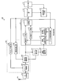
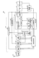
- FIG. 1 is a diagram illustrating a functional configuration of the receiving device 100 according to the first embodiment of the present invention.
- the receiving apparatus 100 includes a receiving antenna 101, an RF (Radio Frequency) circuit unit 102, a timing control unit 103, a frequency control unit 104, a frame detection unit 105, a linear propagation path estimation unit 106, and an equalization processing unit. 107, timing estimation unit 108, frequency estimation unit 109, demapping unit 110, FEC (Forward Error Correction) unit 111, and reference signal generation unit 112.
- RF Radio Frequency
- the equalization processing unit 107 includes a linear filter unit 113, a nonlinear filter unit 114, a filter addition unit 115, a linear filter coefficient holding unit 116, a polynomial filter coefficient holding unit 117, and a filter coefficient control unit 118.
- the timing control unit 103, the frequency control unit 104, the timing estimation unit 108, and the frequency estimation unit 109 constitute a synchronization processing unit 120.
- the receiving antenna 101 receives a radio signal from a transmitting device (not shown) via a propagation path.
- the receiving antenna 101 inputs a received signal to the RF circuit unit 102.
- the RF circuit unit 102 down-converts the received signal input from the receiving antenna 101 and converts it into a baseband signal.
- the RF circuit unit 102 may include an A / D (Analog / Digital) converter, generates a baseband signal based on various frequency conversion techniques, and sends the generated baseband signal to the timing control unit 103. input.
- a / D Analog / Digital
- the timing control unit 103 performs sampling value interpolation processing, resampling processing, and the like so that the output signal has a predetermined oversample ratio, and controls at least one of the symbol timing of the output signal and the sampling clock.
- the timing control unit 103 can use timing phase information generated by a timing estimation unit 108 to be described later, symbol clock frequency control information, and the like.
- the timing control unit 103 inputs an output signal to the frequency control unit 104.
- the frequency control unit 104 performs frequency correction based on the estimation result of the frequency deviation input from the frequency estimation unit 109 described later.
- the frequency control unit 104 can also remove the frequency deviation based on the frequency estimation result input from the frame detection unit 105 described later.
- the input of the frequency estimation result from the frame detection unit 105 can be omitted.
- the frequency control unit 104 inputs the frequency-corrected received signal to the frame detection unit 105 and the linear filter unit 113 and the nonlinear filter unit 114 of the equalization processing unit 107.
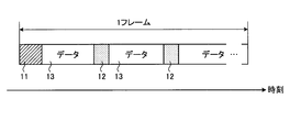
- FIG. 2 is a diagram showing a frame configuration of a signal received by the receiving apparatus 100 shown in FIG.
- the signal received by the receiving apparatus 100 includes a header part 11, a pilot part 12, and a data part 13 in one frame.
- the header part 11 includes a known signal.
- This frame configuration is the same as the single carrier transmission format used in DVB-S2 (Digital Video Broadcasting-Satellite-Second Generation) and DVB-S2X.
- the header portion 11 corresponds to a PL (Physical Layer) header, and the PL header includes an SOF (Start Of Frame) that is a known signal.
- PL Physical Layer
- the frame detection unit 105 detects the frame timing by correlating with the SOF, and inputs the timing estimation result and the received signal at the time corresponding to the SOF to the linear propagation path estimation unit 106. As described above, the frame detection unit 105 may estimate the frequency based on the correlation processing with the known signal, and input the frequency estimation result to the frequency control unit 104. Note that the frame configuration shown in FIG. 2 is an example, and a single carrier transmission frame format including a known signal can be used. Further, the arrangement of known signals in the frame is not particularly limited.
- the linear propagation path estimation unit 106 performs propagation path estimation based on a known signal included in the received signal input from the frame detection unit 105, and estimates an initial value of the filter coefficient of the linear filter unit 113.
- the linear propagation path estimation unit 106 inputs the calculated initial value of the filter coefficient to the linear filter coefficient holding unit 116 of the equalization processing unit 107.
- FIG. 3 is a diagram showing a detailed functional configuration of the linear propagation path estimation unit 106 shown in FIG.
- the linear propagation path estimation unit 106 includes a known signal extraction unit 201, a known signal holding unit 202, an inverse matrix calculation unit 203, and a filter coefficient calculation unit 204.
- the known signal extraction unit 201 extracts a known signal from the reception signal input from the frame detection unit 105.
- the known signal extracted by the known signal extraction unit 201 includes the influence of the distortion component of the propagation path.
- the known signal extraction unit 201 inputs the extracted known signal to the inverse matrix calculation unit 203.
- the inverse matrix calculation unit 203 generates an inverse matrix from the known signal input from the known signal extraction unit 201.
- the inverse matrix calculation unit 203 inputs the generated inverse matrix to the filter coefficient calculation unit 204.
- the known signal holding unit 202 holds an ideal known signal that does not include the influence of the distortion component, and inputs this known signal to the filter coefficient calculation unit 204.
- the filter coefficient calculation unit 204 calculates a filter coefficient based on the inverse matrix input from the inverse matrix calculation unit 203 and the ideal known signal input from the known signal holding unit 202.
- the filter coefficient calculated by the filter coefficient calculation unit 204 is an initial value of the filter coefficient of the linear filter unit 113.
- the equalization processing unit 107 performs equalization processing using the received signal input from the frequency control unit 104 and the filter coefficient input from the linear propagation path estimation unit 106, and the received signal after the equalization processing is processed. Input to the timing estimation unit 108, the frequency estimation unit 109, and the demapping unit 110.
- the equalization processing unit 107 first performs a first equalization process of filtering by the linear filter unit 113 in which the initial value of the filter coefficient is set. After that, when a predetermined condition is satisfied, the linear filter unit 113 and A second equalization process which is an adaptive equalization process filtered by the nonlinear filter unit 114 is performed.
- the equalization processing unit 107 In the first equalization process, the equalization processing unit 107 outputs the received signal filtered by the linear filter unit 113 to the synchronization processing unit 120. In the second equalization process, the equalization processing unit 107 outputs the addition result of the reception signal filtered by the linear filter unit 113 and the reception signal filtered by the nonlinear filter unit 114 to the synchronization processing unit 120.
- the linear filter unit 113 is a FIR (Finite Impulse Response) type digital filter that performs convolution.
- the nonlinear filter unit 114 is, for example, a filter component obtained by removing a linear component from the Volterra filter. Further, the nonlinear filter unit 114 may be configured with a third-order component based on a memory polynomial.
- the sampling value of the nth received signal is y (n)
- the output pf out (n) of the polynomial filter having the tap length l + 1 is expressed by the following formula (1).
- pf out (n) w (0)
- w (k) is the coefficient of the kth polynomial filter.
- k is an integer from 0 to l.
- Each of the linear filter unit 113 and the non-linear filter unit 114 converts the oversampled signal into a shift register constituting the FIR filter at a time by the number of oversamples, thereby converting the signal to a 1-time oversample output. be able to. Further, by shifting one sample at a time to the shift register, it is possible to output in an oversampled state.
- the linear filter unit 113 uses the filter coefficient held in the linear filter coefficient holding unit 116.
- the nonlinear filter unit 114 uses the filter coefficient held in the polynomial filter coefficient holding unit 117.
- the filter coefficient held in the linear filter coefficient holding unit 116 is the initial value of the filter coefficient input by the linear propagation path estimation unit 106, and is then updated by the filter coefficient control unit 118.
- the filter coefficient held in the polynomial filter coefficient holding unit 117 has an initial value of zero, and is then updated by the filter coefficient control unit 118.
- the filter addition unit 115 adds the output of the linear filter unit 113 and the output of the nonlinear filter unit 114 to generate an equalization result.
- the filter addition unit 115 inputs the generated equalization result to each of the timing estimation unit 108, the frequency estimation unit 109, and the demapping unit 110.
- the filter coefficient control unit 118 controls the filter coefficients of the linear filter unit 113 and the nonlinear filter unit 114. Specifically, the filter coefficient control unit 118 uses the linear filter unit 113 and does not use the non-linear filter unit 114 until the predetermined condition is satisfied after the signal is first detected. Thus, the equalization processing unit 107 performs the first equalization process using the filter coefficient of the linear filter unit 113 as the filter coefficient calculated by the linear propagation path estimation unit 106.
- the first equalization process is an equalization process that uses a fixed filter coefficient.
- the filter coefficient control unit 118 can set the non-linear filter unit 114 not to be used by fixing the filter coefficient of the non-linear filter unit 114 to zero. Alternatively, the filter adding unit 115 may not use the nonlinear filter unit 114 by outputting only the output of the linear filter unit 113 as an equalization result without adding the outputs of the nonlinear filter unit 114.
- the filter coefficient control unit 118 can start the second equalization process using both the linear filter unit 113 and the nonlinear filter unit 114 when a predetermined condition is satisfied.
- the second equalization process is an adaptive equalization process in which filter coefficients are controlled by an adaptive algorithm based on a reference signal generated by a reference signal generation unit 112 described later.
- LMS Least Mean Square
- the conditions for starting the second equalization process are, for example, at least the time after the synchronization processing unit 120 starts the synchronization process, the number of processed samples after the synchronization process starts, and the signal quality after the equalization process It may be based on one.
- the number of processed samples after the start of the synchronization process can be the number of samples processed by the timing estimation unit 108 or the frequency estimation unit 109 described later.
- the filter coefficient control unit 118 can start the second equalization process.
- the signal quality after the equalization processing is expressed based on an error amount between the reference value obtained from the result of the hard decision of the output of the equalization processing unit 107 by the demapping unit 110 and the output of the equalization processing unit 107. Can do.
- the signal quality after the equalization processing can be expressed based on whether or not an error is detected after the FEC unit 111 performs error correction using an error correction code.
- the second equalization process may be started when the error amount is equal to or smaller than the threshold value, or the second equalization process may be started when no error is detected.
- the timing estimation unit 108 estimates the timing of the symbol timing phase, generates timing phase information indicating the estimation result, and inputs the generated timing phase information to the timing control unit 103. While the equalization processing unit 107 fixes the filter coefficient, a phenomenon may occur in which the symbol timing phase gradually shifts due to a sampling clock shift.
- the timing estimation unit 108 estimates a symbol timing phase shift using a multiplication tank method or the like, and the timing control unit 103 compensates for the timing phase shift by interpolation based on the timing phase information generated by the timing estimation unit 108. By doing so, it is possible to suppress the occurrence of a shift in symbol timing phase.
- the frequency estimation unit 109 estimates the frequency deviation based on the received signal input from the equalization processing unit 107 and inputs the estimation result to the frequency control unit 104.
- the frequency estimation unit 109 observes the phase rotation by, for example, using a reference signal obtained by averaging the phase rotation of the received signal or performing a hard decision process once and using an adaptive filter based on a 1-tap LMS.
- the frequency deviation can be estimated.
- the frequency estimation unit 109 may estimate the frequency deviation by observing the phase fluctuation between the pilot units 12.
- reception signal output from the equalization processing unit 107 uses a fractional interval equalization method for handling an oversampled reception signal, a signal obtained by sampling a Nyquist point that is ideally symbol-synchronized. Is output.
- phase distortion due to nonlinear distortion components and frequency errors is added.
- the nonlinear distortion component a reception signal that can be demodulated at a bit error rate of about 1% is often obtained depending on the back-off value.
- the frequency deviation is observed in the received signal as a phase rotation in units smaller than several degrees per symbol excluding fluctuation due to noise. For this reason, the frequency estimation unit 109 estimates the frequency deviation, and the frequency control unit 104 performs frequency correction based on the estimation result, thereby suppressing the influence of the frequency deviation.
- the demapping unit 110 performs a soft decision process, a hard decision process, a deinterleave process, and the like necessary for the FEC unit 111 to perform error correction.
- the demapping unit 110 will be described as performing a hard decision, but the demapping unit 110 may perform both a soft decision process and a hard decision process, or among the soft decision process and the hard decision process. You may do one.
- the demapping unit 110 outputs the result of the hard decision process to each of the FEC unit 111 and the reference signal generation unit 112.
- the FEC unit 111 performs error correction using an error correction code based on the result of the hard decision process input from the demapping unit 110, and outputs the result as a decoding result. Further, the FEC unit 111 can determine whether or not the data has been correctly decoded using a checksum or the like, and can input a data string obtained by re-encoding a signal determined to be correctly decoded to the reference signal generation unit 112.
- the reference signal generation unit 112 generates a reference signal used for the equalization processing unit 107 to perform adaptive equalization processing, and inputs the generated reference signal to the filter coefficient control unit 118 of the equalization processing unit 107.
- the reference signal generation unit 112 performs mapping based on at least one of the hard decision result input from the demapping unit 110 and the re-encoded data sequence input from the FEC unit 111, and converts the result into a reference signal.
- the reference signal is input to the filter coefficient control unit 118.
- the reference signal generation unit 112 When the reference signal generation unit 112 generates a reference signal based on the data string input from the FEC unit 111, the time for the FEC unit 111 to perform error correction processing becomes long and the delay amount increases. For this reason, in a state where the processing delay cannot be tolerated, the reference signal generation unit 112 does not use the data string input from the FEC unit 111 and uses the reference signal based on the hard decision result input from the demapping unit 110. Can be generated. Further, in a section where there is data for which the FEC unit 111 has failed in error correction, the reference signal generation unit 112 may generate a reference signal based on the hard decision result input from the demapping unit 110. Further, in a section in which a known signal such as a pilot or SOF is included, the reference signal generation unit 112 can also use the known signal as a reference signal as it is.
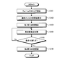
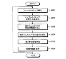
- FIG. 4 is a flowchart showing the operation of the receiving apparatus 100 shown in FIG.
- the frame detection unit 105 of the receiving apparatus 100 performs a frame timing detection process for detecting a part of a known signal (step S101).
- the frame detection unit 105 extracts a received signal corresponding to the known signal based on the detection result and inputs the received signal to the linear propagation path estimation unit 106.
- the linear propagation path estimation unit 106 performs propagation path estimation processing using the input received signal, and calculates the initial value of the filter coefficient of the linear filter unit 113 (step S102).
- the equalization processing unit 107 uses the calculated initial value to start a first equalization process that is performed using the linear filter unit 113 and not using the nonlinear filter unit 114 (step S103).
- the signal after the equalization processing output from the equalization processing unit 107 in the first equalization processing is a signal sequence including Nyquist point sample data.
- the frequency estimation unit 109 performs frequency estimation processing on the sample data string of Nyquist points (step S104). Specifically, the frequency estimation unit 109 performs processing to remove the influence of data bits for each modulation method, for example, if the modulation method is QPSK (Quadrature Phase Shift Keying), performs frequency quadrature processing, and frequency deviation from phase variation Or the frequency deviation can be estimated from the amount of phase fluctuation between a plurality of known signals at different times.
- QPSK Quadrature Phase Shift Keying
- timing estimation processing by the timing estimation unit 108 may be executed in parallel with the frequency estimation processing.
- the equalization processing unit 107 determines whether or not a predetermined condition is satisfied (step S105). When a predetermined condition is satisfied (step S105: Yes), the equalization processing unit 107 starts a second equalization process that is an adaptive equalization process using the linear filter unit 113 and the nonlinear filter unit 114 ( Step S106). If the predetermined condition is not satisfied (step S105: No), the frequency estimation process in step S104 is repeated.
- FIG. 5 is a flowchart showing a modification of the operation shown in FIG.
- the receiver 100 is required to have high synchronization accuracy. Therefore, in this modification, after the adaptive control of the filter coefficient of the linear filter unit 113 is started, the synchronization accuracy is further increased, and then the adaptive control of the filter coefficient of the nonlinear filter unit 114 is started.
- the processing from step S101 to step S103 shown in FIG. 5 is the same as that in FIG.
- the frequency estimation unit 109 performs the first frequency estimation process based on the received signal that has been equalized only by the linear filter unit 113 using a fixed filter coefficient (step S107). Then, the equalization processing unit 107 determines whether or not a predetermined first condition is satisfied (step S108). When the first condition is satisfied (step S108: Yes), the equalization processing unit 107 starts updating the filter coefficient of the linear filter unit 113 (step S109). When the first condition is not satisfied (step S108: No), the first frequency estimation process in step S107 is repeated.
- the frequency estimation unit 109 performs a second frequency estimation process (step S110).
- the second frequency estimation process improves the frequency estimation accuracy using a longer symbol data string than that used in the first frequency estimation process.
- the equalization processing unit 107 determines whether or not the second condition is satisfied (step S111).
- step S111: Yes the equalization processing unit 107 starts updating the filter coefficient of the nonlinear filter unit 114 (step S112).
- step S111: No the second frequency estimation process of step S110 is repeated.
- the receiving apparatus 100 By performing the operation shown in FIG. 5, the receiving apparatus 100 gradually increases the synchronization accuracy from the state where the synchronization is incomplete, and suppresses adverse effects on the feedback processing by the adaptive algorithm and the operation of the adaptive algorithm itself. However, it is possible to improve reception performance by finally realizing highly accurate equalization processing.
- the linear filter unit 113 is used without using the nonlinear filter unit 114, such as setting the filter coefficient of the nonlinear filter unit 114 to zero.
- the first equalization process is performed using the initial value of the filter coefficient obtained by the channel estimation using the known signal, and the received signal after the first equalization process is used for synchronization. Processing is performed. Then, after increasing the synchronization accuracy, the second equalization process, which is an adaptive equalization process, is started. Therefore, even when the number of filter taps is large and the number of filter coefficients to be calculated is larger than the number of symbols of the known signal, the filter coefficients can be calculated.
- the filter coefficient control unit 118 can individually control the timing at which the adaptive control of the filter coefficient of the linear filter unit 113 is started and the timing at which the adaptive control of the filter coefficient of the nonlinear filter unit 114 is started. As a result, it is possible to suppress adverse effects of the feedback process of the adaptive algorithm on the operation of the synchronization process and the adaptive algorithm itself.
- FIG. FIG. 6 is a diagram showing a configuration of the linear propagation path estimation unit 106-1 according to the second embodiment of the present invention.
- the receiving apparatus according to the second embodiment is obtained by replacing the linear propagation path estimation unit 106 of the receiving apparatus 100 shown in FIG. 1 with the linear propagation path estimation unit 106-1 shown in FIG. The description is omitted because it is the same as 100.
- the linear channel estimation unit 106-1 includes a known signal extraction unit 201, a known signal holding unit 202, a band limiting filter information holding unit 301, a replica generation unit 302, a channel calculation unit 303, and a channel reverse characteristic.
- a calculation unit 304 and an interpolation unit 305 are included.
- the functions of the known signal extraction unit 201 and the known signal holding unit 202 are the same as those in the first embodiment.
- the known signal extraction unit 201 inputs the extracted known signal to the propagation path calculation unit 303.
- the known signal holding unit 202 outputs the held known signal to the replica generation unit 302.
- the band limit filter information holding unit 301 holds band limit filter information which is a coefficient of the FIR filter corresponding to the band limit and roll-off filter coefficient on the transmission side.
- the band limiting filter information holding unit 301 may hold the weight in a state where the influence of the RF circuit unit 102 and the band limiting filter on the receiving side is convolved.
- the band limit filter information holding unit 301 can input the band limit filter information held in the replica generation unit 302 and the propagation path inverse characteristic calculation unit 304.
- the replica generation unit 302 generates a replica, which is a received signal sequence that has been waveform-shaped in an oversampled state, using the band-limited filter information and the known signal input from the known signal holding unit 202.
- the replica generation unit 302 inputs the generated replica to the interpolation unit 305.
- the interpolation unit 305 can input the propagation path calculation unit 303 by shifting the replica sampling timing input from the replica generation unit 302.
- the interpolation unit 305 can input a plurality of replicas generated at different timing offsets to the propagation path calculation unit 303 and the propagation path inverse characteristic calculation unit 304.
- the propagation path calculation unit 303 performs propagation path estimation based on the replica generated by the replica generation unit 302 and the known signal extracted from the received signal. Specifically, propagation path calculation section 303 performs propagation path estimation by multiplying the inverse matrix of the matrix composed of replica components and the matrix composed of received signal components. The propagation path calculation unit 303 inputs the propagation path estimation result to the propagation path inverse characteristic calculation unit 304. At this time, the propagation path calculation unit 303 generates a plurality of propagation path estimation results using each of the plurality of replicas input from the interpolation unit 305, and selects one of the plurality of propagation path estimation results. Thus, the selected propagation path estimation result can be input to the propagation path inverse characteristic calculation unit 304. For example, the propagation path calculation unit 303 can select a candidate having the smallest sum of absolute values of filter coefficients from a plurality of propagation path estimation results.
- Propagation path inverse characteristic calculation section 304 includes band limit filter information input from band limit filter information holding section 301, a replica input from interpolation section 305, and a channel estimation result input from propagation path calculation section 303. Based on the above, a propagation path estimation value that takes into account the influence of waveform shaping, which is the propagation path inverse characteristic, is calculated. The propagation path inverse characteristic calculation unit 304 converts the calculated propagation path estimation value into the filter coefficient of the linear filter unit 113 and outputs it.
- Bandwidth filter information can be calculated in advance. For this reason, information on the reverse characteristics to be generated can also be generated in advance. By reducing the information amount of the component that fluctuates according to the propagation path and calculating some inverse characteristics in advance, it is possible to reduce the calculation load of the inverse characteristic calculation.
- the inverse characteristic of the propagation path is not directly calculated, but the inverse characteristic is identified after the propagation path is identified.
- the filter coefficient of the optimization processor 107 is generated. Thereby, the tap length of the propagation path to be calculated can be reduced, and the configuration of the inverse matrix calculation process is facilitated.
- the propagation path characteristic can be estimated based on the shape information of the transmission-side band restriction filter, excluding the influence of the band restriction filter.
- the number of variables to be estimated can be reduced even when the tap length of the filter of the equalization processing unit 107 tends to be long, such as when the roll-off rate is small. Even if the number of symbols of the known signal is small, the filter coefficient of the equalization processing unit 107 can be determined.
- the interpolation unit 305 generates a plurality of known signal sequences generated at a plurality of different timing offsets. For this reason, the replica generation unit 302 generates a plurality of replicas based on each of the plurality of known signal sequences. If the timing of the replica generated by the replica generation unit 302 and the signal generated by the known signal extraction unit 201 are shifted, the value of the component of the propagation path component excluding the influence of the band limiting filter varies. As described above, by performing propagation path estimation based on each of a plurality of known signal sequences generated at a plurality of different timing offsets, it is possible to reduce the influence of this timing shift.
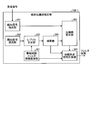
- FIG. 7 is a diagram illustrating a functional configuration of the receiving device 500 according to the third embodiment of the present invention.
- the receiving apparatus 500 according to the third embodiment is used in a system where burst signals arrive discontinuously in time.
- a system in which burst signals arrive discontinuously in time is a system in which signals arrive at predetermined intervals from the same terminal using, for example, TDMA (Time Division Multiple Access) technology.
- TDMA Time Division Multiple Access
- FIG. 8 is a diagram illustrating a configuration of a signal received by the receiving device 500 illustrated in FIG.
- the signal received by receiving apparatus 500 is a burst signal that is divided in time by TDMA and arrives discontinuously in units of frames.
- receiving apparatus 500 receives a signal.
- the time slot TS1 is referred to as the current time slot at the time when the time slot TS1 is received
- the time slot TS0 can be referred to as the previous time slot because the time slot TS0 is the time slot that received the previous signal.
- the time slot TS2 can be referred to as the next time slot.
- the current time slot is time slot TS2
- the previous time slot is time slot TS1.
- the received signal in the current time slot may be referred to as the current received signal
- the received signal in the previous time slot may be referred to as the past received signal.
- FIG. 8 illustrates an example in which a signal arrives at the receiving device 500 with a fixed interval frame by frame. However, a plurality of frames may arrive together at the receiving device 500, and the arrival interval may be constant. It does not have to be.
- the receiving apparatus 500 includes a receiving antenna 101, an RF circuit unit 102, a timing control unit 503, a frequency control unit 504, a frame detection unit 505, a linear propagation path estimation unit 506, an equalization processing unit 507, a timing
- the estimation unit 508, the frequency estimation unit 509, the phase control unit 510, the control information storage unit 530, the demapping unit 110, the FEC unit 111, and the reference signal generation unit 112 are included.
- the timing control unit 503, the frequency control unit 504, the timing estimation unit 508, the frequency estimation unit 509, and the phase control unit 510 may be collectively referred to as a synchronization processing unit 520.
- the equalization processing unit 507 includes a linear filter unit 113, a nonlinear filter unit 114, a filter addition unit 115, a linear filter coefficient holding unit 116, a polynomial filter coefficient holding unit 117, and a filter coefficient control unit 518.
- constituent elements having the same functions and operations as the receiving apparatus 100 are assigned the same names and reference numerals as those in the first embodiment, and redundant description is omitted.
- constituent elements having the same functions as those of receiving apparatus 100 and having different operations are assigned the same names and different reference numerals as in the first embodiment.
- components different from the receiving apparatus 100 will be mainly described.
- the control information storage unit 530 is a reception signal after the synchronization processing unit 520 performs the synchronization processing, and includes synchronization information indicating the synchronization state of the reception signal input to the equalization processing unit 507, and the equalization processing unit 507. Save the filter coefficients.
- the synchronization information and the filter coefficient can be collectively referred to as control information.
- the synchronization information includes timing information indicating the sampling timing of the reception signal after correction by the timing control unit 503 of the synchronization processing unit 520, and a frequency control value used by the frequency control unit 504 of the synchronization processing unit 520 for frequency correction of the reception signal. Including frequency information.
- the synchronization information further includes the phase value of the received signal input to the equalization processing unit 507.
- the filter coefficient includes the filter coefficient of the linear filter unit 113 and the filter coefficient of the nonlinear filter unit 114.
- the timing at which the control information storage unit 530 stores the control information may be a regular timing such as once per frame, or may be a timing requested by the control information storage unit 530.
- the synchronization processing unit 520 has a function of reading the synchronization information stored when processing the past received signal from the control information storage unit 530 and using the past synchronization information to perform a synchronization process on the current received signal. Have. Specifically, the synchronization processing unit 520 obtains a difference between the read past synchronization information and the synchronization information of the current reception signal, and corrects the current reception signal based on the obtained difference. More specifically, in addition to the function of the timing control unit 103, the timing control unit 503 obtains a difference in timing information included in the synchronization information, and corrects the sampling timing of the current received signal so as to interpolate the difference. To do.
- the phase control unit 510 obtains a difference between the phase information included in the synchronization information, and corrects the phase of the current received signal so as to interpolate the difference.
- the frequency control unit 504 can correct the frequency of the current received signal using the frequency control value indicated by the frequency information included in the past synchronization information. Thus, it is not necessary to perform frequency estimation by reusing past frequency information. In addition, frequency estimation may be performed when frequency fluctuation is larger than the time slot interval and it is difficult to reuse frequency information.
- the receiving apparatus 500 When the receiving apparatus 500 receives a burst signal as shown in FIG. 8, first, the baseband signal generated by the receiving antenna 101 and the RF circuit unit 102 is input to the timing control unit 503 of the synchronization processing unit 520.
- the current time slot is the time slot TS1
- the timing control unit 503 receives the past control information from the control information storage unit 530, for example, the time slot TS0 that is the previous time slot.
- the past timing information is extracted from the control information, and the difference between the sampling timings is obtained using the current timing information and the past timing information.
- the timing control unit 503 corrects the sampling timing so as to interpolate the obtained difference. By such a function, it is possible to correct a sampling timing shift that occurs between the previous time slot and the current time slot, and it is possible to perform equalization processing by reusing the filter coefficients.
- the stored timing information may be corrected instead of correcting the sampling timing of the received signal.
- the timing control unit 503 reads the past timing information from the control information storage unit 530, corrects the past timing information so as to interpolate the difference from the current timing information, and stores the control information again.
- the corrected timing information is stored in the unit 530. Examples of the timing correction method include resampling processing using an interpolation filter that slightly changes the sampling point of the signal. Any method may be used as long as the sampling timing can be corrected.
- the timing control unit 503 inputs the received signal after performing the correction process to the frequency control unit 504.
- the frequency control unit 504 can read the past frequency information stored in the control information storage unit 530 and reuse the frequency control value indicated by the frequency information. In this case, the frequency estimation process can be omitted. When the frequency control value is not reused, the frequency control unit 504 may perform frequency estimation processing.
- the phase control unit 510 reads out phase information indicating the phase value of the received signal assumed by the filter coefficient of the past time slot, for example, the time slot TS0 which is the previous time slot, from the control information storage unit 530, and outputs a frame described later. A difference from the phase estimation value of the received signal in the current time slot output by the detection unit 505 is obtained.
- the phase control unit 510 has a function of controlling the phase of the received signal based on the obtained difference. By using such a function, the phase of the received signal after equalization when the equalization process is performed by reusing the filter coefficients can be made as expected. Further, the phase controller 510 may rotate the phase of the stored filter coefficient instead of correcting the phase of the received signal.
- the phase control unit 510 reads the phase information from the control information storage unit 530, rotates the phase indicated by the read phase information, and again converts the phase information indicating the phase after the rotation into the control information storage unit 530. You can save it.
- the phase control unit 510 inputs the received signal after controlling the phase to the frame detection unit 505, the linear filter unit 113, and the nonlinear filter unit 114.
- the frame detection unit 505 has a function of estimating the phase value of the reception signal based on the correlation value between the reception signal and the SOF that is a known signal. By using this function, the phase of the received signal in the current time slot can be recognized, and the phase control unit 510 can correct the phase of the current received signal. Also, the frame detection unit 505 inputs the received signal at the time corresponding to the SOF obtained at the time of frame detection to the timing estimation unit 508 in order to estimate the sampling timing assumed by the filter coefficient used in the current time slot. It also has a function. The function of inputting the received signal at the time corresponding to the SOF to the linear propagation path estimation unit 506 operates only when the linear propagation path estimation unit 506 operates.
- the linear propagation path estimator 506 has the same function as the linear propagation path estimator 106, but the filter coefficient in the previous time slot is stored in the control information storage unit 530, and the stored filter coefficient is reused. When equalization processing is performed, the linear propagation path estimation unit 506 does not operate. In this case, the linear propagation path estimation unit 506 outputs nothing to the linear filter coefficient holding unit 116. When only the filter coefficient of the nonlinear filter unit 114 is reused, the linear propagation path estimation unit 506 performs initial value estimation of the linear filter unit 113 as with the linear propagation path estimation unit 106.
- the equalization processing unit 507 performs an equalization process that is a filtering process using the linear filter unit 113 and the nonlinear filter unit 114 on the reception signal input from the phase control unit 510.
- the linear filter unit 113 uses the filter coefficient input from the linear filter coefficient holding unit 116
- the nonlinear filter unit 114 uses the filter coefficient input from the polynomial filter coefficient holding unit 117.
- the adaptive equalization process is performed from the beginning without dividing the first equalization process and the second equalization process as shown in the first embodiment.
- a bi-equalization process can be executed.
- the equalization processing unit 507 may execute the first equalization process in order as in the first and second embodiments. Also, when it is not necessary to perform nonlinear equalization in the current time slot, for example, when the number of modulation multilevels is small, only the linear filter coefficient of the previous time slot is reused, and linear equalization is performed without using the nonlinear filter coefficient. You may only do it.
- the estimation accuracy of the frame detection unit 505 and the timing estimation unit 508 When the estimation accuracy of the frame detection unit 505 and the timing estimation unit 508 is low, a reference signal for LMS update can be generated, but the equalization output error is large and the demodulation performance of the head portion of the received signal is deteriorated There is. In this case, only the head portion of the received signal can be input to the equalization processing unit 507 a plurality of times, and the filter coefficients can be adapted to the received signal to be demodulated before demodulating all the received signals. By such an operation, the estimation accuracy of the frame detection unit 505 and the timing estimation unit 508 is low, and it is possible to suppress the problem that the demodulation performance of the head portion of the received signal is degraded when the filter coefficient is reused.
- the equalization processing unit 507 inputs the equalized reception signal to the demapping unit 110, the frequency estimation unit 509, and the timing estimation unit 508.
- the filter coefficient control unit 518 controls the filter coefficients of the linear filter unit 113 and the nonlinear filter unit 114. Specifically, when the filter coefficient control unit 518 first detects a received signal, the filter coefficient used in the previous time slot is read from the control information storage unit 530, and the read filter coefficient is read by the linear filter unit 113 and the nonlinear filter. It can be applied to the part 114. However, as described above, when the nonlinear filter unit 114 is not used, the filter coefficient control unit 518 can read and apply only the filter coefficient of the linear filter unit 113.
- the filter coefficient control unit 518 also has a function of storing the filter coefficient in the control information storage unit 530 in order to use the filter coefficient of the current time slot in the next time slot.
- the timing at which the filter coefficient control unit 518 stores the filter coefficient may be a regular timing such as once per frame, or may be a timing requested from the control information storage unit 530.
- the timing estimation unit 508 also has a function of estimating the sampling timing of the received signal in the current time slot by taking a sliding correlation between the SOF sequence input from the frame detection unit 505 and the known sequence. Have. Further, when the accuracy of estimating the sampling timing is insufficient, the timing estimation unit 508 can upsample the received signal or the known sequence to improve the resolution of the estimated value. The timing estimation unit 508 inputs timing information generated by such a function to the timing control unit 503.
- the frequency estimation unit 509 performs frequency estimation processing for estimating a frequency deviation based on the received signal input from the equalization processing unit 507, and inputs frequency information indicating an estimated value to the frequency control unit 504.
- the frequency estimation unit 509 has the same function as the frequency estimation unit 109. However, as described above, when there is no large frequency fluctuation from the previous time slot, the frequency estimation process described above is performed by using past frequency information. Can be omitted.
- the functions of the demapping unit 110, the FEC unit 111, and the reference signal generation unit 112 are the same as those in the first embodiment.
- FIG. 9 is a flowchart showing the operation of the receiving device 500 shown in FIG.
- the frame detection unit 505 of the reception device 500 performs a frame timing detection process for detecting a part of the known signal (step S501).
- the frame detection unit 505 extracts a received signal corresponding to the known signal based on the detection result and inputs the received signal to the timing estimation unit 508.
- the frame detection unit 505 calculates the phase of the received signal from the correlation value when detecting the frame, detects the calculated phase as an initial phase value, and inputs the detected initial phase value to the phase control unit 510.
- the timing estimation unit 508 estimates the sampling timing using the input received signal, and inputs timing information indicating the estimation result to the timing control unit 503 (step S502).
- the synchronization processing unit 520 reads the control information of the previous time slot stored in the control information storage unit 530 (step S503). Specifically, the timing control unit 503 reads timing information indicating the past received signal sampling timing from the control information of the previous time slot stored in the control information storage unit 530.
- the frequency control unit 504 reads past frequency information from the control information of the previous time slot stored in the control information storage unit 530.
- the phase control unit 510 reads phase information from the control information of the previous time slot stored in the control information storage unit 530.
- the synchronization processing unit 520 corrects the difference between the control information of the previous time slot and the control information of the current time slot (step S504).
- the timing control unit 503 obtains a difference between the past sampling timing indicated by the read timing information and the estimated value input from the timing estimation unit 508 so that the filter coefficient can be reused.
- the received signal is interpolated and the stored filter coefficient is resampled to correct the difference.
- the frequency control unit 504 corrects the received signal using the read frequency information.
- the phase control unit 510 obtains a difference between the read phase information and the phase information of the current reception signal input from the frame detection unit 505, and controls the phase of the current reception signal based on the obtained difference. By applying a phase rotation to the stored filter coefficients, the filter coefficients can be reused.
- the equalization processing unit 507 When the sampling timing, the initial phase of the input received signal, and the frequency control amount are obtained, the equalization processing unit 507 performs the filter coefficient of the linear filter unit 113 and the filter of the nonlinear filter unit 114 used in the previous time slot.
- the second equalization process which is an adaptive equalization process for updating the filter coefficients of the linear filter unit 113 and the nonlinear filter unit 114, is started using the coefficients (step S505).
- the synchronization processing unit 520 and the equalization processing unit 507 store the filter coefficient and the synchronization information as control information in the control information storage unit 530 (step S506).
- the stored control information is used in the next time slot process.
- steps S501 to S506 shown in FIG. 9 even when a burst signal used in TDMA is received, nonlinear equalization is performed without re-determining the filter coefficient each time the signal is received. Processing can be performed.
- Step S505 may be executed after executing a step (not shown) for performing equalization processing from the above and adapting the filter coefficient to the received signal.
- filter coefficients used in the past for example, filter coefficients used in the previous time slot are reused. By doing so, it is possible to realize nonlinear equalization processing without re-estimating the filter coefficients.
- the method of reusing past control information can be applied in a system where a burst signal arrives as long as past control information is stored.
- the second equalization process is started, and the update of the filter coefficient starts.
- the conversion processing unit 507 and the synchronization processing unit 520 may store the updated filter coefficient and the synchronization information.
- the filter coefficient and the synchronization information stored here are reused when processing the received signal that arrives thereafter.
- FIG. 10 is a block diagram showing a functional configuration of a receiving device 500a according to the fourth embodiment of the present invention.
- the reception device 500a includes a frequency estimation equalization processing unit including a linear filter unit 113, a nonlinear filter unit 114, and a filter addition unit 115 in addition to the configuration of the reception device 500 according to the third embodiment. 507a.
- the same parts as those of the receiving apparatus 500 are denoted by the same reference numerals, and the description thereof is omitted.
- the frequency estimation equalization processing unit 507a is provided in parallel with the equalization processing unit 507, and the linear filter unit 113 and the nonlinear filter unit 114 of the frequency estimation equalization processing unit 507a include a phase control unit of the synchronization processing unit 520.
- the reception signal output from 510 is input.
- the frequency estimation equalization processing unit 507a captures the filter coefficient used by the equalization processing unit 507.
- the frequency estimation equalization processing unit 507a applies the captured filter coefficients to the linear filter unit 113 and the non-linear filter unit 114 of the frequency estimation equalization processing unit 507a, fixes the filter coefficients, and updates them by LMS. Without performing this, the received signal input from the phase control unit 510 is equalized.
- the frequency estimation equalization processing unit 507 a inputs the received signal after the equalization processing to the timing estimation unit 508 and the frequency estimation unit 509.
- the configuration of the present embodiment is effective when demodulating a small clock deviation below the resolution controllable by the timing control unit 503 while correcting the sampling timing by the LMS.
- the frequency estimation unit 509 Since the frequency deviation that should be estimated by the frequency estimation unit 509 is also followed, the frequency estimation unit 509 There is a case where the estimated value is not a value originally desired to be estimated. Therefore, as described above, the frequency estimation equalization processing unit 507a and the equalization processing unit 507 for performing the demodulation while following the clock deviation and performing the demodulation at a later stage are separately operated in parallel. By doing so, it is possible to realize nonlinear equalization processing that follows the clock deviation while obtaining high frequency estimation accuracy.
- the frequency estimation equalization processing unit 507a periodically captures the filter coefficients of the equalization processing unit 507.
- the capture cycle may be a predetermined number of samples, or may be a cycle including a frame head or a known signal. Alternatively, timing determined by other methods can be used.
- the equalization output signal input to the timing estimation unit 508 is the reception signal output from the frequency estimation equalization processing unit 507a. However, if the clock deviation tracking by the LMS is sufficient, equalization is performed. Timing estimation using the output signal may not be executed.
- the circuit configuration of the receiving device 500a is increased by the frequency estimation equalization processing unit 507a, and the circuit scale necessary for the equalization processing is approximately doubled. For this reason, when there is no room for resources, the processing may be divided in time series, and the frequency equalization processing and equalization processing may be alternately executed in time division. In this case, time division processing can be realized using the configuration of the receiving apparatus 500 shown in FIG. In FIG. 10, the same signal is input to the frequency estimation equalization processing unit 507 a and the equalization processing unit 507, but the signal input to the frequency control unit 504 is input to the frequency estimation equalization processing unit 507 a. It may be entered sideways.
- the frequency estimation equalization processing unit 507a is separated from the demodulation equalization processing unit 507 that follows the clock deviation.
- the frequency estimation accuracy can be maintained while following the clock deviation, and as a result, the demodulation performance of nonlinear equalization can be improved.
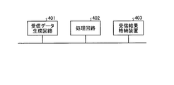
- FIG. 11 is a diagram illustrating an example in which the receiving apparatuses 100, 500, and 500a illustrated in FIGS. 1, 7, and 10 are configured using dedicated hardware.
- the functions of the receiving devices 100, 500, and 500 a can be realized using the received data generation circuit 401, the processing circuit 402, and the reception result storage device 403.
- the reception data generation circuit 401 acquires a reception signal from the antenna.
- the processing circuit 402 performs baseband processing for compensating for distortion.
- the processing circuit 402 is, for example, a circuit such as an FPGA (Field Programmable Gate Array) or an LSI (Large Scale Integration).
- the sharing between the processing executed by the reception data generation circuit 401 and the processing executed by the processing circuit 402 can be changed as necessary.
- the reception result storage device 403 stores the data demodulated by the processing circuit 402 as a reception result.
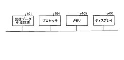
- FIG. 12 is a diagram illustrating an example in which the receiving apparatuses 100, 500, and 500a illustrated in FIGS. 1, 7, and 10 are configured using software.
- the functions of the reception devices 100, 500, and 500 a can be realized using the reception data generation circuit 401, the processor 404, the memory 405, and the display 406.
- the processor 404 reads out and executes a computer program for performing distortion compensation from the memory 405, thereby realizing each function of the receiving devices 100, 500, and 500a.
- the processor 404 is a CPU (Central Processing Unit) and is also called a central processing unit, a processing unit, an arithmetic unit, a microprocessor, a microcomputer, a DSP (Digital Signal Processor), or the like.
- CPU Central Processing Unit
- DSP Digital Signal Processor
- the memory 405 is, for example, a nonvolatile or volatile semiconductor memory such as RAM (Random Access Memory), ROM (Read Only Memory), flash memory, EPROM (Erasable Programmable ROM), EEPROM (registered trademark) (Electrically EPROM), Magnetic disks, flexible disks, optical disks, compact disks, mini disks, DVDs (Digital Versatile Disks), etc.
- the memory 405 is also used as a temporary memory in each process executed by the processor 404, and a waveform, a filter coefficient, a set value, and the like, which are data during the process of the processor 404, are read and written.
- the display 406 is a display device that displays the processing result.
- the receiving apparatuses 100, 500, and 500a are provided with the display 406.
- apparatuses other than the receiving apparatuses 100, 500, and 500a that operate by obtaining the demodulation result may include the display 406.
- the configuration described in the above embodiment shows an example of the contents of the present invention, and can be combined with another known technique, and can be combined with other configurations without departing from the gist of the present invention. It is also possible to omit or change the part.
- the FEC unit 111 may be omitted from the receivers 100, 500, and 500a.
- the receiving apparatuses 100, 500, and 500a are provided with a phase compensation function in front of the frequency estimation unit 109 to follow the fluctuation in the phase offset of the received signal and filter A process of correcting the amount of deviation from the observed reference phase may be added to the output or the filter input.
- a waveform shaping filter having a fixed coefficient such as a roll-off filter may be provided at a later stage than the RF circuit unit 102.
- reception system with nonlinear distortion compensation it is particularly high in the transmission system with multi-level and high coding rate that operates at a high SNR (Signal-Noise Ratio) with the driving power of the amplifier having large nonlinear distortion.
- a performance improvement effect can be obtained.
- the influence of white noise is dominant, and the performance improvement effect is limited.
- addition processing of a multi-value filter is performed based on modulation method information (MODDCOD) included in a frame or information indicating at least one coding rate May be able to be stopped.
- MODDCOD modulation method information
- 11 header section, 12 pilot section, 13 data section 100, 500, 500a receiving device, 101 receiving antenna, 102 RF circuit section, 103, 503 timing control section, 104, 504 frequency control section, 105, 505 frame detection section, 106, 106-1, 506 linear propagation path estimation unit, 107, 507 equalization processing unit, 108, 508 timing estimation unit, 109, 509 frequency estimation unit, 110 demapping unit, 111 FEC unit, 112 reference signal generation unit, 113 linear filter unit, 114 nonlinear filter unit, 115 filter addition unit, 116 linear filter coefficient holding unit, 117 polynomial filter coefficient holding unit, 118, 518 filter coefficient control unit, 120, 520 synchronization processing unit, 201 known signal extraction unit, 202 Known signal holding unit, 203 inverse matrix calculation unit, 204 filter coefficient calculation unit, 301 band-limited filter information holding unit, 302 replica generation unit, 303 propagation path calculation unit, 304 propagation path inverse characteristic calculation unit, 305 interpolation unit, 401
Landscapes
- Engineering & Computer Science (AREA)
- Computer Networks & Wireless Communication (AREA)
- Signal Processing (AREA)
- Power Engineering (AREA)
- Cable Transmission Systems, Equalization Of Radio And Reduction Of Echo (AREA)
Abstract
Description
図1は、本発明の実施の形態1にかかる受信装置100の機能構成を示す図である。受信装置100は、受信アンテナ101と、RF(Radio Frequency)回路部102と、タイミング制御部103と、周波数制御部104と、フレーム検出部105と、線形伝搬路推定部106と、等化処理部107と、タイミング推定部108と、周波数推定部109と、デマッピング部110と、FEC(Forward Error Correction)部111と、参照信号生成部112とを有する。
FIG. 1 is a diagram illustrating a functional configuration of the
pfout(n)=w(0)|y(n)|2y(n)+w(1)|y(n-1)|2y(n-1)+…+w(l)|y(n-l)|2y(n-l) …(1) The
pf out (n) = w (0) | y (n) | 2 y (n) + w (1) | y (n−1) | 2 y (n−1) +... + w (l) | y (n −l) | 2 y (n−l) (1)
図6は、本発明の実施の形態2にかかる線形伝搬路推定部106-1の構成を示す図である。実施の形態2にかかる受信装置は、図1に示す受信装置100の線形伝搬路推定部106を図6に示す線形伝搬路推定部106-1に置き換えたものであり、その他の構成は受信装置100と同様であるため、説明を省略する。 Embodiment 2. FIG.
FIG. 6 is a diagram showing a configuration of the linear propagation path estimation unit 106-1 according to the second embodiment of the present invention. The receiving apparatus according to the second embodiment is obtained by replacing the linear propagation
図7は、本発明の実施の形態3にかかる受信装置500の機能構成を示す図である。実施の形態3にかかる受信装置500は、時間的に非連続にバースト信号が到来するシステムにおいて用いられる。時間的に非連続にバースト信号が到来するシステムとは、例えばTDMA(Time Division Multiple Access:時分割多重アクセス)技術を用いて、同一の端末から定められた間隔で信号が到来するシステムである。 Embodiment 3 FIG.
FIG. 7 is a diagram illustrating a functional configuration of the receiving
図10は、本発明の実施の形態4にかかる受信装置500aの機能構成を示すブロック図である。図10に示すように、受信装置500aは、実施の形態3にかかる受信装置500の構成に加えて、線形フィルタ部113、非線形フィルタ部114およびフィルタ加算部115を含む周波数推定用等化処理部507aを有する。受信装置500aの機能構成のうち、受信装置500と同様の部分については同じ符号を付することで説明を省略し、以下では、受信装置500と異なる点について主に説明する。 Embodiment 4 FIG.
FIG. 10 is a block diagram showing a functional configuration of a
Claims (19)
- 線形フィルタ部と、非線形フィルタ部とを含み、受信信号の等化処理を行う等化処理部と、
受信信号に含まれる既知信号を用いて伝搬路推定を行い、前記線形フィルタ部のフィルタ係数を算出する線形伝搬路推定部と、
前記等化処理部が出力する信号に基づいて、周波数偏差を補正する同期処理を行う同期処理部と、
を備え、
前記等化処理部は、前記線形フィルタ部によりフィルタリングされた受信信号を前記同期処理部へ出力する第1等化処理を実行した後、予め定められた条件が満たされると、前記線形フィルタ部によりフィルタリングされた受信信号と前記非線形フィルタ部によりフィルタリングされた受信信号との加算結果を前記同期処理部へ出力する適応等化処理である第2等化処理を開始することを特徴とする受信装置。 An equalization processing unit that includes a linear filter unit and a non-linear filter unit, and performs equalization processing of a received signal;
Performing a channel estimation using a known signal included in the received signal, and calculating a filter coefficient of the linear filter unit;
A synchronization processing unit for performing a synchronization process for correcting a frequency deviation based on a signal output from the equalization processing unit;
With
The equalization processing unit performs a first equalization process of outputting the reception signal filtered by the linear filter unit to the synchronization processing unit, and then, when a predetermined condition is satisfied, the linear filter unit 2. A receiving apparatus comprising: starting a second equalization process that is an adaptive equalization process for outputting a result of adding a filtered received signal and a received signal filtered by the nonlinear filter unit to the synchronization processing unit. - 前記同期処理部は、シンボルタイミング位相の推定結果に基づいて、タイミング位相を補償するタイミング制御部と、タイミング位相を補償後の信号を用いて周波数補正を行う周波数制御部と、
を含むことを特徴とする請求項1に記載の受信装置。 The synchronization processing unit, based on the estimation result of the symbol timing phase, a timing control unit that compensates the timing phase, a frequency control unit that performs frequency correction using the signal after compensating the timing phase,
The receiving apparatus according to claim 1, comprising: - 前記等化処理部は、前記線形フィルタ部のフィルタ係数と、前記非線形フィルタ部のフィルタ係数とを制御するフィルタ係数制御部を有し、
前記フィルタ係数制御部は、前記第2等化処理において、前記線形フィルタ部のフィルタ係数の更新を開始した後、前記非線形フィルタ部のフィルタ係数の更新を開始することを特徴とする請求項1または2に記載の受信装置。 The equalization processing unit includes a filter coefficient control unit that controls a filter coefficient of the linear filter unit and a filter coefficient of the nonlinear filter unit,
The filter coefficient control unit starts updating the filter coefficient of the nonlinear filter unit after starting update of the filter coefficient of the linear filter unit in the second equalization processing. 2. The receiving device according to 2. - 前記同期処理部は、前記線形フィルタ部がフィルタ係数の初期値を使用している状態で前記周波数偏差を推定する第1の周波数推定処理を行い、前記線形フィルタ部のフィルタ係数の更新が開始された後、前記非線形フィルタ部のフィルタ係数の更新が開始される前に、前記周波数偏差を推定する第2の周波数推定処理を行う周波数推定部を有することを特徴とする請求項3に記載の受信装置。 The synchronization processing unit performs a first frequency estimation process for estimating the frequency deviation in a state where the linear filter unit uses an initial value of a filter coefficient, and updating of the filter coefficient of the linear filter unit is started. 4. The reception according to claim 3, further comprising: a frequency estimation unit that performs a second frequency estimation process for estimating the frequency deviation before starting to update the filter coefficient of the nonlinear filter unit. 5. apparatus.
- 前記非線形フィルタ部は、メモリ多項式を用いた多項式フィルタであることを特徴とする請求項1に記載の受信装置。 The receiving apparatus according to claim 1, wherein the nonlinear filter unit is a polynomial filter using a memory polynomial.
- 前記受信信号に含まれる変調方式および符号化率の少なくとも1つを示す情報に基づいて、前記非線形フィルタ部を使用するか否かを切り替えることを特徴とする請求項1に記載の受信装置。 The receiving apparatus according to claim 1, wherein whether or not to use the nonlinear filter unit is switched based on information indicating at least one of a modulation scheme and a coding rate included in the received signal.
- 前記線形伝搬路推定部は、送信側の帯域制限フィルタの形状情報を用いて前記伝搬路推定を行うことを特徴とする請求項1に記載の受信装置。 The receiving apparatus according to claim 1, wherein the linear propagation path estimation unit performs the propagation path estimation using shape information of a band limiting filter on a transmission side.
- 前記線形伝搬路推定部は、オーバサンプルされた既知信号列を生成し、当該既知信号列に基づいて、前記帯域制限フィルタの影響を除く伝搬路成分を推定することを特徴とする請求項7に記載の受信装置。 8. The linear propagation path estimation unit generates an oversampled known signal sequence and estimates a propagation path component excluding the influence of the band limiting filter based on the known signal sequence. The receiving device described.
- 前記線形伝搬路推定部は、異なるタイミングオフセットで生成した複数の前記既知信号列を生成し、複数の前記既知信号列のそれぞれに基づいて、前記帯域制限フィルタの影響を除く伝搬路成分を推定することを特徴とする請求項8に記載の受信装置。 The linear channel estimation unit generates a plurality of the known signal sequences generated at different timing offsets, and estimates a channel component excluding the influence of the band limiting filter based on each of the plurality of known signal sequences. The receiving device according to claim 8.
- 予め定められた前記条件は、前記同期処理を開始してからの時間、前記同期処理を開始してからの処理サンプル数、および等化処理後の信号品質の少なくとも1つに基づくことを特徴とする請求項1に記載の受信装置。 The predetermined condition is based on at least one of a time since the start of the synchronization process, a number of processed samples after the synchronization process is started, and a signal quality after the equalization process, The receiving device according to claim 1.
- 前記受信信号は、時間的に非連続なバースト信号であり、
前記等化処理部に入力される受信信号の同期状態を示す同期情報と、前記等化処理部のフィルタ係数とを保存する制御情報保存部、
をさらに備え、
前記同期処理部は、過去の受信信号を処理する際に保存された前記同期情報を使用して、現在の受信信号に対する前記同期処理を行い、
前記等化処理部は、過去の受信信号を処理する際に保存された前記フィルタ係数を使用して、現在の受信信号に対する前記第2等化処理を行うことを特徴とする請求項1から10のいずれか1項に記載の受信装置。 The received signal is a burst signal that is discontinuous in time,
A control information storage unit that stores synchronization information indicating a synchronization state of a received signal input to the equalization processing unit and a filter coefficient of the equalization processing unit;
Further comprising
The synchronization processing unit performs the synchronization processing on the current received signal using the synchronization information stored when processing the past received signal,
The said equalization process part performs the said 2nd equalization process with respect to the present received signal using the said filter coefficient preserve | saved when processing the past received signal. The receiving device according to any one of the above. - 前記同期情報は、前記等化処理部に入力される受信信号の位相情報を含み、
前記制御情報保存部に保存されている過去の受信信号の位相情報と、現在の受信信号の位相情報との差分に基づいて、現在の受信信号の位相を制御する機能を有する位相制御部、
をさらに備えることを特徴とする請求項11に記載の受信装置。 The synchronization information includes phase information of a received signal input to the equalization processing unit,
A phase control unit having a function of controlling the phase of the current received signal based on the difference between the phase information of the past received signal stored in the control information storing unit and the phase information of the current received signal;
The receiving device according to claim 11, further comprising: - 前記同期情報は、前記等化処理部に入力される受信信号のシンボルタイミングを示すタイミング情報を含み、
シンボルタイミングのずれを推定して推定結果を示すタイミング情報を生成するタイミング推定部と、
前記制御情報保存部に保存されている過去の受信信号のタイミング情報と、前記タイミング推定部が出力する現在の受信信号のタイミング情報との差分に基づいて、現在の受信信号のサンプリングタイミングを変化させるタイミング制御部と、
をさらに備えることを特徴とする請求項11または12に記載の受信装置。 The synchronization information includes timing information indicating a symbol timing of a reception signal input to the equalization processing unit,
A timing estimator that estimates timing of symbol timing and generates timing information indicating an estimation result;
Based on the difference between the timing information of the past received signal stored in the control information storage unit and the timing information of the current received signal output by the timing estimation unit, the sampling timing of the current received signal is changed. A timing control unit;
The receiving apparatus according to claim 11, further comprising: - 前記等化処理部の前記線形フィルタ部のフィルタ係数と、前記非線形フィルタ部のフィルタ係数とをキャプチャし、キャプチャしたフィルタ係数を用いて、フィルタ係数を固定した状態でフィルタリングした周波数推定用の信号を出力する周波数推定用等化部、
をさらに備えることを特徴とする請求項1から13のいずれか1項に記載の受信装置。 The filter coefficient of the linear filter unit of the equalization processing unit and the filter coefficient of the nonlinear filter unit are captured, and the signal for frequency estimation filtered with the filter coefficient fixed is captured using the captured filter coefficient. An equalizer for estimating the frequency to be output,
The receiving apparatus according to claim 1, further comprising: - 時間的に非連続に到来するバースト信号を受信する受信装置であって、
線形フィルタ部と非線形フィルタ部とを含み、受信信号の等化処理を行う等化処理部と、
入力される受信信号を補正する同期処理を行う同期処理部と、
前記等化処理部に入力される受信信号の同期状態を示す同期情報と、前記等化処理部のフィルタ係数とを保存する制御情報保存部と、
を備え、
前記同期処理部は、過去の受信信号を処理する際に前記制御情報保存部に保存された前記同期情報を用いて、現在の受信信号に対する前記同期処理を行い、
前記等化処理部は、過去の受信信号を処理する際に前記制御情報保存部に保存された前記フィルタ係数を使用して、前記線形フィルタ部によりフィルタリングされた受信信号と前記非線形フィルタ部によりフィルタリングされた受信信号との加算結果を前記同期処理部へ出力する適応等化処理を行うことを特徴とする受信装置。 A receiving device for receiving a burst signal that arrives discontinuously in time,
An equalization processing unit that includes a linear filter unit and a non-linear filter unit, and performs equalization processing of a received signal;
A synchronization processing unit for performing a synchronization process for correcting an input received signal;
A control information storage unit that stores synchronization information indicating a synchronization state of a received signal input to the equalization processing unit, and a filter coefficient of the equalization processing unit;
With
The synchronization processing unit performs the synchronization processing on the current received signal using the synchronization information stored in the control information storage unit when processing a past received signal,
The equalization processing unit filters the received signal filtered by the linear filter unit and the non-linear filter unit using the filter coefficient stored in the control information storage unit when processing a past received signal. An adaptive equalization process for outputting an addition result with the received signal to the synchronization processing unit. - 前記同期情報は、前記等化処理部に入力される受信信号のサンプリングタイミングを示すタイミング情報、前記受信信号の位相情報、および前記受信信号の周波数情報を含み、
前記フィルタ係数は、前記線形フィルタ部のフィルタ係数と、前記非線形フィルタ部のフィルタ係数とを含むことを特徴とする請求項15に記載の受信装置。 The synchronization information includes timing information indicating a sampling timing of a reception signal input to the equalization processing unit, phase information of the reception signal, and frequency information of the reception signal,
The receiving apparatus according to claim 15, wherein the filter coefficient includes a filter coefficient of the linear filter unit and a filter coefficient of the nonlinear filter unit. - 受信信号を受信する受信装置が、
前記受信信号に含まれる既知信号を用いて伝搬路推定を行い、線形フィルタ部のフィルタ係数を算出するステップと、
算出したフィルタ係数を用いた第1等化処理において線形フィルタ部によりフィルタリングされた受信信号に基づき周波数偏差を補正する同期処理を行うステップと、
予め定められた条件が満たされると、前記線形フィルタ部によりフィルタリングされた受信信号と非線形フィルタ部によりフィルタリングされた受信信号との加算結果を等化処理の結果として出力する第2等化処理を開始するステップと、
前記線形フィルタ部および前記非線形フィルタ部のフィルタ係数を適応アルゴリズムを用いて更新するステップと、
を実行することを特徴とする受信信号処理方法。 A receiving device that receives the received signal
Performing propagation path estimation using a known signal included in the received signal and calculating a filter coefficient of a linear filter unit;
Performing a synchronization process for correcting a frequency deviation based on the received signal filtered by the linear filter unit in the first equalization process using the calculated filter coefficient;
When a predetermined condition is satisfied, a second equalization process is started to output the addition result of the reception signal filtered by the linear filter unit and the reception signal filtered by the nonlinear filter unit as a result of the equalization process And steps to
Updating filter coefficients of the linear filter unit and the nonlinear filter unit using an adaptive algorithm;
And a received signal processing method. - 時間的に非連続なバースト信号を受信する受信装置が、
前記更新するステップを実行した後に、
前記線形フィルタ部および前記非線形フィルタ部を含む等化処理部に入力された信号の同期状態を示す同期情報と、前記等化処理部のフィルタ係数とを制御情報保存部に保存するステップと、
受信信号が入力されると、当該受信信号のサンプリングタイミングおよび位相を推定するステップと、
前記制御情報保存部に保存されている、過去に推定したタイミング位相情報および位相情報を読み込み、現在の受信信号の推定値と比較するステップと、
比較結果に基づいて、受信信号を補正するステップと、
前記制御情報保存部に保存されている過去のフィルタ係数を用いて、補正後の前記受信信号に対して等化処理を行い、前記線形フィルタ部および前記非線形フィルタ部のフィルタ係数を適応アルゴリズムを用いて更新するステップと、
を繰り返し実行することを特徴とする請求項17に記載の受信信号処理方法。 A receiving device that receives a burst signal that is not continuous in time,
After performing the updating step,
Storing synchronization information indicating a synchronization state of a signal input to an equalization processing unit including the linear filter unit and the nonlinear filter unit, and a filter coefficient of the equalization processing unit in a control information storage unit;
When a received signal is input, estimating the sampling timing and phase of the received signal;
Reading the timing phase information and phase information estimated in the past, stored in the control information storage unit, and comparing with the estimated value of the current received signal;
Correcting the received signal based on the comparison result;
Using the past filter coefficients stored in the control information storage unit, the corrected received signal is equalized, and the filter coefficients of the linear filter unit and the nonlinear filter unit are applied using an adaptive algorithm Update step,
The received signal processing method according to claim 17, wherein the received signal processing is repeatedly executed. - 時間的に非連続なバースト信号を受信する受信装置が、
受信信号に含まれる既知信号を用いて受信信号のサンプリングタイミングおよび位相を推定するステップと、
制御情報保存部に保存された、過去に推定したサンプリングタイミングおよび位相を示す情報を読み込み、現在の受信信号のサンプリングタイミングおよび位相の推定結果と比較するステップと、
比較結果に基づいて、受信信号を補正するステップと、
前記制御情報保存部に保存されている過去のフィルタ係数を用いて、補正した前記受信信号に等化処理を行い、線形フィルタ部および非線形フィルタ部のそれぞれのフィルタ係数を適応アルゴリズムを用いて更新するステップと、
前記推定するステップにおいて推定された前記サンプリングタイミングを示すタイミング位相情報および前記位相を示す位相情報と、前記受信信号の周波数情報と、前記フィルタ係数とを前記制御情報保存部に保存するステップと、
を繰り返し実行することを特徴とする受信信号処理方法。 A receiving device that receives a burst signal that is not continuous in time,
Estimating the sampling timing and phase of the received signal using a known signal included in the received signal;
Reading information indicating the sampling timing and phase estimated in the past, stored in the control information storage unit, and comparing with the sampling timing and phase estimation result of the current received signal;
Correcting the received signal based on the comparison result;
Using the past filter coefficients stored in the control information storage unit, the corrected received signal is equalized, and the respective filter coefficients of the linear filter unit and the nonlinear filter unit are updated using an adaptive algorithm. Steps,
Storing the timing phase information indicating the sampling timing and the phase information indicating the phase estimated in the estimating step, the frequency information of the received signal, and the filter coefficient in the control information storage unit;
Is repeatedly executed. A received signal processing method.
Priority Applications (4)
| Application Number | Priority Date | Filing Date | Title |
|---|---|---|---|
| CA3093079A CA3093079C (en) | 2018-03-08 | 2018-11-02 | Reception device, reception signal processing method, control circuit, and recording medium |
| JP2020504772A JP6746030B2 (en) | 2018-03-08 | 2018-11-02 | Receiver, received signal processing method, control circuit and storage medium |
| US16/964,443 US11196459B2 (en) | 2018-03-08 | 2018-11-02 | Reception device, reception signal processing method, control circuit, and recording medium |
| EP18909156.4A EP3748862A4 (en) | 2018-03-08 | 2018-11-02 | Reception device, and reception signal processing method |
Applications Claiming Priority (2)
| Application Number | Priority Date | Filing Date | Title |
|---|---|---|---|
| PCT/JP2018/009062 WO2019171551A1 (en) | 2018-03-08 | 2018-03-08 | Reception device, and reception signal processing method |
| JPPCT/JP2018/009062 | 2018-03-08 |
Publications (1)
| Publication Number | Publication Date |
|---|---|
| WO2019171655A1 true WO2019171655A1 (en) | 2019-09-12 |
Family
ID=67845942
Family Applications (2)
| Application Number | Title | Priority Date | Filing Date |
|---|---|---|---|
| PCT/JP2018/009062 WO2019171551A1 (en) | 2018-03-08 | 2018-03-08 | Reception device, and reception signal processing method |
| PCT/JP2018/040872 WO2019171655A1 (en) | 2018-03-08 | 2018-11-02 | Reception device, and reception signal processing method |
Family Applications Before (1)
| Application Number | Title | Priority Date | Filing Date |
|---|---|---|---|
| PCT/JP2018/009062 WO2019171551A1 (en) | 2018-03-08 | 2018-03-08 | Reception device, and reception signal processing method |
Country Status (5)
| Country | Link |
|---|---|
| US (1) | US11196459B2 (en) |
| EP (1) | EP3748862A4 (en) |
| JP (1) | JP6746030B2 (en) |
| CA (1) | CA3093079C (en) |
| WO (2) | WO2019171551A1 (en) |
Cited By (2)
| Publication number | Priority date | Publication date | Assignee | Title |
|---|---|---|---|---|
| JPWO2021124463A1 (en) * | 2019-12-17 | 2021-06-24 | ||
| WO2021161495A1 (en) * | 2020-02-14 | 2021-08-19 | 三菱電機株式会社 | Receiving device, control circuit, storage medium, and received signal processing method |
Families Citing this family (1)
| Publication number | Priority date | Publication date | Assignee | Title |
|---|---|---|---|---|
| JP7415165B2 (en) * | 2020-03-19 | 2024-01-17 | 富士通株式会社 | Transmission equipment and distortion compensation method |
Citations (8)
| Publication number | Priority date | Publication date | Assignee | Title |
|---|---|---|---|---|
| JPH05327416A (en) * | 1992-05-25 | 1993-12-10 | Sony Corp | Automatic equalizer |
| JPH06204902A (en) * | 1992-12-28 | 1994-07-22 | Nec Corp | Decision feedback type equalizer |
| JPH08274693A (en) * | 1995-03-31 | 1996-10-18 | Fujitsu Ltd | Mlse equalizer and demodulator using the same |
| JP2003258685A (en) | 2001-04-09 | 2003-09-12 | Matsushita Electric Ind Co Ltd | Non-linear distortion equalizer circuit, non-linear distortion equalizing method and non-linear distortion equalizing program |
| JP2004336563A (en) * | 2003-05-09 | 2004-11-25 | Matsushita Electric Ind Co Ltd | Radio reception device and reception filtering method |
| JP2006140910A (en) * | 2004-11-15 | 2006-06-01 | Matsushita Electric Ind Co Ltd | Waveform equalization method, waveform equalizer, radio equipment and radio communication system |
| JP2006295766A (en) * | 2005-04-14 | 2006-10-26 | Matsushita Electric Ind Co Ltd | Nonlinear distortion equalization system |
| WO2017130314A1 (en) * | 2016-01-27 | 2017-08-03 | 三菱電機株式会社 | Receiving device |
Family Cites Families (7)
| Publication number | Priority date | Publication date | Assignee | Title |
|---|---|---|---|---|
| JP3102221B2 (en) * | 1993-09-10 | 2000-10-23 | 三菱電機株式会社 | Adaptive equalizer and adaptive diversity equalizer |
| US7142616B2 (en) | 2001-04-09 | 2006-11-28 | Matsushita Electric Industrial Co., Ltd. | Front end processor for data receiver and nonlinear distortion equalization method |
| US6628707B2 (en) * | 2001-05-04 | 2003-09-30 | Radiant Networks Plc | Adaptive equalizer system for short burst modems and link hopping radio networks |
| US8837626B2 (en) * | 2011-12-09 | 2014-09-16 | Lsi Corporation | Conditional adaptation of linear filters in a system having nonlinearity |
| US20110069749A1 (en) * | 2009-09-24 | 2011-03-24 | Qualcomm Incorporated | Nonlinear equalizer to correct for memory effects of a transmitter |
| US9231792B1 (en) * | 2015-01-21 | 2016-01-05 | Nitero Pty Ltd. | Adaptive WiGig equalizer |
| US9614659B2 (en) * | 2015-01-28 | 2017-04-04 | Texas Instruments Incorporated | CTLE gear shifting to enable CDR frequency lock in wired communication |
-
2018
- 2018-03-08 WO PCT/JP2018/009062 patent/WO2019171551A1/en active Application Filing
- 2018-11-02 US US16/964,443 patent/US11196459B2/en active Active
- 2018-11-02 WO PCT/JP2018/040872 patent/WO2019171655A1/en unknown
- 2018-11-02 JP JP2020504772A patent/JP6746030B2/en active Active
- 2018-11-02 EP EP18909156.4A patent/EP3748862A4/en not_active Withdrawn
- 2018-11-02 CA CA3093079A patent/CA3093079C/en active Active
Patent Citations (8)
| Publication number | Priority date | Publication date | Assignee | Title |
|---|---|---|---|---|
| JPH05327416A (en) * | 1992-05-25 | 1993-12-10 | Sony Corp | Automatic equalizer |
| JPH06204902A (en) * | 1992-12-28 | 1994-07-22 | Nec Corp | Decision feedback type equalizer |
| JPH08274693A (en) * | 1995-03-31 | 1996-10-18 | Fujitsu Ltd | Mlse equalizer and demodulator using the same |
| JP2003258685A (en) | 2001-04-09 | 2003-09-12 | Matsushita Electric Ind Co Ltd | Non-linear distortion equalizer circuit, non-linear distortion equalizing method and non-linear distortion equalizing program |
| JP2004336563A (en) * | 2003-05-09 | 2004-11-25 | Matsushita Electric Ind Co Ltd | Radio reception device and reception filtering method |
| JP2006140910A (en) * | 2004-11-15 | 2006-06-01 | Matsushita Electric Ind Co Ltd | Waveform equalization method, waveform equalizer, radio equipment and radio communication system |
| JP2006295766A (en) * | 2005-04-14 | 2006-10-26 | Matsushita Electric Ind Co Ltd | Nonlinear distortion equalization system |
| WO2017130314A1 (en) * | 2016-01-27 | 2017-08-03 | 三菱電機株式会社 | Receiving device |
Non-Patent Citations (1)
| Title |
|---|
| See also references of EP3748862A4 |
Cited By (5)
| Publication number | Priority date | Publication date | Assignee | Title |
|---|---|---|---|---|
| JPWO2021124463A1 (en) * | 2019-12-17 | 2021-06-24 | ||
| JP7106017B2 (en) | 2019-12-17 | 2022-07-25 | 三菱電機株式会社 | Wireless receiver, control circuit, storage medium and wireless communication method |
| WO2021161495A1 (en) * | 2020-02-14 | 2021-08-19 | 三菱電機株式会社 | Receiving device, control circuit, storage medium, and received signal processing method |
| JPWO2021161495A1 (en) * | 2020-02-14 | 2021-08-19 | ||
| JP7004879B2 (en) | 2020-02-14 | 2022-01-21 | 三菱電機株式会社 | Receiver, control circuit, storage medium and received signal processing method |
Also Published As
| Publication number | Publication date |
|---|---|
| US20210050883A1 (en) | 2021-02-18 |
| JP6746030B2 (en) | 2020-08-26 |
| CA3093079C (en) | 2023-07-11 |
| US11196459B2 (en) | 2021-12-07 |
| JPWO2019171655A1 (en) | 2020-06-18 |
| CA3093079A1 (en) | 2019-09-12 |
| EP3748862A1 (en) | 2020-12-09 |
| EP3748862A4 (en) | 2021-04-07 |
| WO2019171551A1 (en) | 2019-09-12 |
Similar Documents
| Publication | Publication Date | Title |
|---|---|---|
| US9209843B2 (en) | Fine phase estimation for highly spectrally efficient communications | |
| JP6746030B2 (en) | Receiver, received signal processing method, control circuit and storage medium | |
| US6952570B2 (en) | Wireless communication receiver that determines frequency offset | |
| JP2008543186A (en) | An adaptive interpolator for channel estimation. | |
| WO2006093389A1 (en) | Channel equalizer and method of equalizing a channel | |
| KR102207829B1 (en) | Communication Apparatus and Method for High Efficiency Satellite Service | |
| EP2159980B1 (en) | Apparatus and method for receiving orthogonal frequency division multiplexed signals | |
| JP7004879B2 (en) | Receiver, control circuit, storage medium and received signal processing method | |
| CN107113262B (en) | Local oscillator phase noise tracking for single carrier transmission | |
| JP2007201729A (en) | Adaptive equalizer and receiver | |
| JP4822946B2 (en) | Adaptive equalizer | |
| EP1259040A2 (en) | Equalisation for QAM signals | |
| JP4795274B2 (en) | Adaptive equalizer | |
| JP2007235407A (en) | Adaptive equalizer and communication apparatus | |
| JP7106017B2 (en) | Wireless receiver, control circuit, storage medium and wireless communication method | |
| JP4796212B1 (en) | Receiving apparatus and receiving method | |
| CN111106925B (en) | Timing synchronization method for reducing steady-state error | |
| JP5812827B2 (en) | Receiver | |
| KR100218671B1 (en) | The system of compensating rayleigh fading | |
| JP4822945B2 (en) | Adaptive equalizer | |
| US20040042546A1 (en) | Single carrier receiver with an equalizer for improving equalization quality and equalization method thereof | |
| JP6156603B1 (en) | Demodulator | |
| CN107005259B (en) | The method and apparatus for reducing the adjacent-channel interference in wlan system | |
| JP2008271409A (en) | Receiving apparatus | |
| JP2001102975A (en) | Equalizer and receiver using same |
Legal Events
| Date | Code | Title | Description |
|---|---|---|---|
| 121 | Ep: the epo has been informed by wipo that ep was designated in this application |
Ref document number: 18909156 Country of ref document: EP Kind code of ref document: A1 |
|
| ENP | Entry into the national phase |
Ref document number: 2020504772 Country of ref document: JP Kind code of ref document: A |
|
| ENP | Entry into the national phase |
Ref document number: 3093079 Country of ref document: CA |
|
| NENP | Non-entry into the national phase |
Ref country code: DE |
|
| ENP | Entry into the national phase |
Ref document number: 2018909156 Country of ref document: EP Effective date: 20200901 |