WO2019167868A1 - Method for manufacturing slab and continuous casting equipment - Google Patents
Method for manufacturing slab and continuous casting equipment Download PDFInfo
- Publication number
- WO2019167868A1 WO2019167868A1 PCT/JP2019/007014 JP2019007014W WO2019167868A1 WO 2019167868 A1 WO2019167868 A1 WO 2019167868A1 JP 2019007014 W JP2019007014 W JP 2019007014W WO 2019167868 A1 WO2019167868 A1 WO 2019167868A1
- Authority
- WO
- WIPO (PCT)
- Prior art keywords
- slab
- rolling
- friction coefficient
- continuous casting
- cooling
- Prior art date
Links
- 238000009749 continuous casting Methods 0.000 title claims abstract description 46
- 238000004519 manufacturing process Methods 0.000 title claims abstract description 23
- 238000000034 method Methods 0.000 title abstract description 26
- 238000005096 rolling process Methods 0.000 claims abstract description 150
- 238000001816 cooling Methods 0.000 claims abstract description 74
- 238000005461 lubrication Methods 0.000 claims abstract description 53
- 238000004458 analytical method Methods 0.000 claims abstract description 24
- 239000010687 lubricating oil Substances 0.000 claims description 85
- 239000002184 metal Substances 0.000 claims description 25
- 229910052751 metal Inorganic materials 0.000 claims description 25
- 238000005266 casting Methods 0.000 claims description 23
- 230000009467 reduction Effects 0.000 claims description 12
- 238000004804 winding Methods 0.000 claims description 11
- 238000005554 pickling Methods 0.000 description 16
- 239000000498 cooling water Substances 0.000 description 12
- 239000000314 lubricant Substances 0.000 description 12
- 229910000831 Steel Inorganic materials 0.000 description 11
- 230000008569 process Effects 0.000 description 11
- 239000010959 steel Substances 0.000 description 11
- 238000003860 storage Methods 0.000 description 10
- 239000003963 antioxidant agent Substances 0.000 description 7
- 230000003078 antioxidant effect Effects 0.000 description 7
- 239000002826 coolant Substances 0.000 description 7
- 230000007547 defect Effects 0.000 description 7
- XLYOFNOQVPJJNP-UHFFFAOYSA-N water Substances O XLYOFNOQVPJJNP-UHFFFAOYSA-N 0.000 description 7
- 230000000052 comparative effect Effects 0.000 description 6
- 150000002148 esters Chemical class 0.000 description 6
- 238000003825 pressing Methods 0.000 description 6
- 239000002436 steel type Substances 0.000 description 6
- 238000012795 verification Methods 0.000 description 6
- 238000001514 detection method Methods 0.000 description 5
- 239000000839 emulsion Substances 0.000 description 5
- XEEYBQQBJWHFJM-UHFFFAOYSA-N Iron Chemical compound [Fe] XEEYBQQBJWHFJM-UHFFFAOYSA-N 0.000 description 4
- 230000008859 change Effects 0.000 description 4
- 238000010586 diagram Methods 0.000 description 4
- 238000005259 measurement Methods 0.000 description 4
- 239000003921 oil Substances 0.000 description 4
- 235000019198 oils Nutrition 0.000 description 4
- 238000000889 atomisation Methods 0.000 description 3
- 238000005452 bending Methods 0.000 description 3
- 238000004364 calculation method Methods 0.000 description 3
- 238000005520 cutting process Methods 0.000 description 3
- 238000011156 evaluation Methods 0.000 description 3
- 238000010008 shearing Methods 0.000 description 3
- 230000001133 acceleration Effects 0.000 description 2
- 230000003064 anti-oxidating effect Effects 0.000 description 2
- 239000003638 chemical reducing agent Substances 0.000 description 2
- 230000007423 decrease Effects 0.000 description 2
- 229910052742 iron Inorganic materials 0.000 description 2
- 238000002844 melting Methods 0.000 description 2
- 230000008018 melting Effects 0.000 description 2
- 238000000611 regression analysis Methods 0.000 description 2
- 239000007787 solid Substances 0.000 description 2
- 239000007921 spray Substances 0.000 description 2
- 239000002344 surface layer Substances 0.000 description 2
- IJGRMHOSHXDMSA-UHFFFAOYSA-N Atomic nitrogen Chemical compound N#N IJGRMHOSHXDMSA-UHFFFAOYSA-N 0.000 description 1
- 229910000975 Carbon steel Inorganic materials 0.000 description 1
- 239000005069 Extreme pressure additive Substances 0.000 description 1
- 241000135309 Processus Species 0.000 description 1
- QVGXLLKOCUKJST-UHFFFAOYSA-N atomic oxygen Chemical compound [O] QVGXLLKOCUKJST-UHFFFAOYSA-N 0.000 description 1
- 239000002199 base oil Substances 0.000 description 1
- 230000008901 benefit Effects 0.000 description 1
- 230000006835 compression Effects 0.000 description 1
- 238000007906 compression Methods 0.000 description 1
- 230000000994 depressogenic effect Effects 0.000 description 1
- 230000006866 deterioration Effects 0.000 description 1
- 239000003085 diluting agent Substances 0.000 description 1
- 239000012895 dilution Substances 0.000 description 1
- 238000010790 dilution Methods 0.000 description 1
- 229910001873 dinitrogen Inorganic materials 0.000 description 1
- 230000000694 effects Effects 0.000 description 1
- 238000010438 heat treatment Methods 0.000 description 1
- 238000009434 installation Methods 0.000 description 1
- 230000001050 lubricating effect Effects 0.000 description 1
- 238000002156 mixing Methods 0.000 description 1
- 238000012986 modification Methods 0.000 description 1
- 230000004048 modification Effects 0.000 description 1
- 230000001590 oxidative effect Effects 0.000 description 1
- 239000001301 oxygen Substances 0.000 description 1
- 229910052760 oxygen Inorganic materials 0.000 description 1
- 230000002093 peripheral effect Effects 0.000 description 1
- 238000007781 pre-processing Methods 0.000 description 1
- 238000012545 processing Methods 0.000 description 1
- 238000000275 quality assurance Methods 0.000 description 1
- 239000002904 solvent Substances 0.000 description 1
- 238000003756 stirring Methods 0.000 description 1
- 238000011144 upstream manufacturing Methods 0.000 description 1
- 235000015112 vegetable and seed oil Nutrition 0.000 description 1
- 239000008158 vegetable oil Substances 0.000 description 1
Images


Classifications
-
- B—PERFORMING OPERATIONS; TRANSPORTING
- B22—CASTING; POWDER METALLURGY
- B22D—CASTING OF METALS; CASTING OF OTHER SUBSTANCES BY THE SAME PROCESSES OR DEVICES
- B22D11/00—Continuous casting of metals, i.e. casting in indefinite lengths
- B22D11/04—Continuous casting of metals, i.e. casting in indefinite lengths into open-ended moulds
- B22D11/055—Cooling the moulds
-
- B—PERFORMING OPERATIONS; TRANSPORTING
- B22—CASTING; POWDER METALLURGY
- B22D—CASTING OF METALS; CASTING OF OTHER SUBSTANCES BY THE SAME PROCESSES OR DEVICES
- B22D11/00—Continuous casting of metals, i.e. casting in indefinite lengths
- B22D11/16—Controlling or regulating processes or operations
- B22D11/20—Controlling or regulating processes or operations for removing cast stock
-
- B—PERFORMING OPERATIONS; TRANSPORTING
- B21—MECHANICAL METAL-WORKING WITHOUT ESSENTIALLY REMOVING MATERIAL; PUNCHING METAL
- B21B—ROLLING OF METAL
- B21B1/00—Metal-rolling methods or mills for making semi-finished products of solid or profiled cross-section; Sequence of operations in milling trains; Layout of rolling-mill plant, e.g. grouping of stands; Succession of passes or of sectional pass alternations
- B21B1/02—Metal-rolling methods or mills for making semi-finished products of solid or profiled cross-section; Sequence of operations in milling trains; Layout of rolling-mill plant, e.g. grouping of stands; Succession of passes or of sectional pass alternations for rolling heavy work, e.g. ingots, slabs, blooms, or billets, in which the cross-sectional form is unimportant ; Rolling combined with forging or pressing
-
- B—PERFORMING OPERATIONS; TRANSPORTING
- B21—MECHANICAL METAL-WORKING WITHOUT ESSENTIALLY REMOVING MATERIAL; PUNCHING METAL
- B21B—ROLLING OF METAL
- B21B1/00—Metal-rolling methods or mills for making semi-finished products of solid or profiled cross-section; Sequence of operations in milling trains; Layout of rolling-mill plant, e.g. grouping of stands; Succession of passes or of sectional pass alternations
- B21B1/46—Metal-rolling methods or mills for making semi-finished products of solid or profiled cross-section; Sequence of operations in milling trains; Layout of rolling-mill plant, e.g. grouping of stands; Succession of passes or of sectional pass alternations for rolling metal immediately subsequent to continuous casting
- B21B1/463—Metal-rolling methods or mills for making semi-finished products of solid or profiled cross-section; Sequence of operations in milling trains; Layout of rolling-mill plant, e.g. grouping of stands; Succession of passes or of sectional pass alternations for rolling metal immediately subsequent to continuous casting in a continuous process, i.e. the cast not being cut before rolling
-
- B—PERFORMING OPERATIONS; TRANSPORTING
- B22—CASTING; POWDER METALLURGY
- B22D—CASTING OF METALS; CASTING OF OTHER SUBSTANCES BY THE SAME PROCESSES OR DEVICES
- B22D11/00—Continuous casting of metals, i.e. casting in indefinite lengths
- B22D11/06—Continuous casting of metals, i.e. casting in indefinite lengths into moulds with travelling walls, e.g. with rolls, plates, belts, caterpillars
- B22D11/0622—Continuous casting of metals, i.e. casting in indefinite lengths into moulds with travelling walls, e.g. with rolls, plates, belts, caterpillars formed by two casting wheels
-
- B—PERFORMING OPERATIONS; TRANSPORTING
- B22—CASTING; POWDER METALLURGY
- B22D—CASTING OF METALS; CASTING OF OTHER SUBSTANCES BY THE SAME PROCESSES OR DEVICES
- B22D11/00—Continuous casting of metals, i.e. casting in indefinite lengths
- B22D11/12—Accessories for subsequent treating or working cast stock in situ
- B22D11/1206—Accessories for subsequent treating or working cast stock in situ for plastic shaping of strands
-
- B—PERFORMING OPERATIONS; TRANSPORTING
- B21—MECHANICAL METAL-WORKING WITHOUT ESSENTIALLY REMOVING MATERIAL; PUNCHING METAL
- B21B—ROLLING OF METAL
- B21B1/00—Metal-rolling methods or mills for making semi-finished products of solid or profiled cross-section; Sequence of operations in milling trains; Layout of rolling-mill plant, e.g. grouping of stands; Succession of passes or of sectional pass alternations
- B21B1/02—Metal-rolling methods or mills for making semi-finished products of solid or profiled cross-section; Sequence of operations in milling trains; Layout of rolling-mill plant, e.g. grouping of stands; Succession of passes or of sectional pass alternations for rolling heavy work, e.g. ingots, slabs, blooms, or billets, in which the cross-sectional form is unimportant ; Rolling combined with forging or pressing
- B21B2001/028—Slabs
-
- B—PERFORMING OPERATIONS; TRANSPORTING
- B21—MECHANICAL METAL-WORKING WITHOUT ESSENTIALLY REMOVING MATERIAL; PUNCHING METAL
- B21B—ROLLING OF METAL
- B21B2265/00—Forming parameters
- B21B2265/12—Rolling load or rolling pressure; roll force
-
- B—PERFORMING OPERATIONS; TRANSPORTING
- B21—MECHANICAL METAL-WORKING WITHOUT ESSENTIALLY REMOVING MATERIAL; PUNCHING METAL
- B21B—ROLLING OF METAL
- B21B2265/00—Forming parameters
- B21B2265/20—Slip
-
- B—PERFORMING OPERATIONS; TRANSPORTING
- B21—MECHANICAL METAL-WORKING WITHOUT ESSENTIALLY REMOVING MATERIAL; PUNCHING METAL
- B21B—ROLLING OF METAL
- B21B37/00—Control devices or methods specially adapted for metal-rolling mills or the work produced thereby
- B21B37/28—Control of flatness or profile during rolling of strip, sheets or plates
- B21B37/30—Control of flatness or profile during rolling of strip, sheets or plates using roll camber control
- B21B37/32—Control of flatness or profile during rolling of strip, sheets or plates using roll camber control by cooling, heating or lubricating the rolls
-
- B—PERFORMING OPERATIONS; TRANSPORTING
- B21—MECHANICAL METAL-WORKING WITHOUT ESSENTIALLY REMOVING MATERIAL; PUNCHING METAL
- B21B—ROLLING OF METAL
- B21B45/00—Devices for surface or other treatment of work, specially combined with or arranged in, or specially adapted for use in connection with, metal-rolling mills
- B21B45/02—Devices for surface or other treatment of work, specially combined with or arranged in, or specially adapted for use in connection with, metal-rolling mills for lubricating, cooling, or cleaning
- B21B45/0239—Lubricating
- B21B45/0245—Lubricating devices
- B21B45/0248—Lubricating devices using liquid lubricants, e.g. for sections, for tubes
- B21B45/0251—Lubricating devices using liquid lubricants, e.g. for sections, for tubes for strips, sheets, or plates
Definitions
- the present invention relates to a slab manufacturing method and continuous casting equipment. This application claims priority on March 2, 2018 based on Japanese Patent Application No. 2018-037945 filed in Japan, the contents of which are incorporated herein by reference.
- a molten metal storage section is formed by a pair of continuous casting cooling drums (hereinafter referred to as “cooling drums”) and a pair of side weirs arranged opposite to each other in the horizontal direction.
- a thin slab (hereinafter referred to as “slab”) is cast by rotating a pair of cooling drums of the molten metal stored in the storage part (for example, Patent Document 1).
- the cooling drums are rotated in opposite directions to send the molten metal downward as a slab while solidifying and growing on the peripheral surface of the cooling drum.
- the slab sent out from the cooling drum is sent out horizontally by a pinch roll and adjusted to a desired plate thickness by a downstream in-line mill.
- the slab whose plate thickness is adjusted by the in-line mill is wound into a coil by a winding device installed downstream of the in-line mill.
- the cooling drum is generally at a low temperature before the start of casting, and when the casting is started, the temperature is raised by contact with the molten metal. Further, the cooling drum is cooled from the inner surface by a cooling medium (for example, cooling water) so as not to exceed a predetermined temperature.
- a cooling medium for example, cooling water
- the period when the temperature of the cooling drum reaches a predetermined temperature and becomes constant is the steady casting period
- the arbitrary point in the steady casting period is the steady casting
- the temperature of the cooling drum in the steady casting period is the steady temperature .
- the state during the steady casting period is referred to as a steady state.
- the cooling drum profile changes over time from the start of casting until it reaches a steady state. For this reason, the profile of the cooling drum is set so that the plate profile (plate crown) of the slab at the time of steady casting becomes a desired plate profile.
- a dummy sheet is used at the start of casting.
- the leading end of the dummy sheet is set on a coil winder, and the tail end of the dummy sheet is set so as to be sandwiched between twin roll drums.
- the molten metal that becomes the tip of the slab is first cooled and solidified, and then joined to the tail end of the dummy sheet. Thereafter, the cooling drum rotates and is sequentially supplied to the casting coil.
- the thickness of the connecting portion of the dummy sheet is much thicker than the thickness of the slab. This thick part is also referred to as a hump. If the knuckle is strongly pressed or rolled with a pinch roll or in-line mill, meandering or plate breakage will occur, so this part should have a large gap between the upper and lower pinch rolls and the in-line mill work roll (roll gap). Then, the pinch roll and the in-line mill are passed with no compression force applied to the hump.
- the pinch roll After the hump passes the pinch roll, the pinch roll starts to fly.
- the flying touch of the in-line mill depends on the shape control capability of the in-line mill, but after the hump passes the in-line mill, if the shape control capability of the in-line mill is insufficient, the flying touch is started after the steady state, Rolling is performed so that the outlet side plate thickness of the in-line mill becomes a target value. After the hump passes through the in-line mill, if the shape control capability of the in-line mill is sufficient, the flying touch is started from the state before the steady state is reached, and the in-line mill exit side plate thickness is rolled to the target value.
- a concave shape is formed on the surface of the cooling drum of the twin drum type continuous casting apparatus, for example, as described in Patent Document 2.
- Dimple processing is applied. Since the molten metal enters the dimples and hardens, protrusions (hereinafter, simply referred to as “protrusions”) formed by the dimples are formed on the surface of the slab after the cooling drum. As described in Patent Document 3, the shape of the protrusion can be determined by giving priority to casting stability.
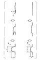
- FIG. 1 is a conceptual diagram showing folding of protrusions formed on a slab.
- the ratio between the height b and the width a of the protrusion d1 is larger than the ratio between the height b and the width a of the protrusion d10.
- the protrusion d1 having a large ratio between the height b and the width a is likely to be folded when the slab is rolled by an in-line mill. Oxide scale c1 on the surface of the slab may be caught in the folding part e where the protrusion d1 is folded.
- the protrusion d10 having a small ratio between the height b and the width a is not easily folded even when rolled by an in-line mill. For this reason, the folding part e does not generate
- the oxidized scale on the slab surface is removed in the next pickling step.
- the oxide scale c1 bitten into the slab folding portion e cannot be sufficiently removed by ordinary pickling.
- the oxide scale is exposed on the surface of the slab and the surface property of the slab deteriorates, and the surface of the slab after rolling is deteriorated. Defects may become apparent.
- an object of the present invention is to occur when a slab having a protrusion formed by a twin drum continuous casting apparatus is rolled by an in-line mill.
- An object of the present invention is to provide a slab manufacturing method and a continuous casting facility that can prevent the protrusions from bending without impairing productivity.
- a molten metal storage section is formed by a pair of cooling drums having dimples formed on the surface and a pair of side weirs, and the molten metal is rotated while the pair of cooling drums is rotated.
- a twin-drum type continuous casting apparatus that casts a slab having protrusions formed by the dimples from the molten metal stored in the storage unit, and a downstream side of the twin-drum type continuous casting apparatus, and cools the slab
- a cooling device that is disposed downstream of the cooling device, an in-line mill that performs one-pass rolling of the slab with a work roll of 10% or more by a work roll, and a downstream of the in-line mill
- a method for producing a slab by a continuous casting facility comprising a coiling device for winding the slab into a coil shape, wherein a rolling load and an advanced rate when the slab is rolled using a rolling analysis model
- the friction coefficient is calculated from the value, the lubrication conditions during rolling of the slab are controlled so that the friction coefficient falls within a predetermined range, and the deformation resistance model based on the Owanan theory and the approximate expression of Shida as the rolling analysis model
- the predetermined range is 0.15 or more and 0.25 or less when the coefficient of friction is calculated
- the height of the protrusion may be not less than 50 ⁇ m and not more than 100 ⁇ m.
- the lubrication condition is a supply amount of lubricating oil supplied to at least one of the work roll or the cast slab. May be.
- a molten metal reservoir is formed by a pair of cooling drums having dimples formed on the surface and a pair of side weirs, and the molten metal is rotated while rotating the pair of cooling drums.
- a twin-drum type continuous casting apparatus that casts a slab having protrusions formed by the dimples from the molten metal stored in the storage unit, and a downstream side of the twin-drum type continuous casting apparatus, and cools the slab
- a cooling device that is disposed downstream of the cooling device, an in-line mill that performs one-pass rolling of the slab with a work roll of 10% or more by a work roll, and a downstream of the in-line mill, Using a winding device for winding the piece into a coil, a measuring device for actually measuring the rolling load and the advanced rate of the slab rolled by the in-line mill, and a rolling analysis model, the rolling load and A friction coefficient is calculated from the measured value of the advanced rate, and a lubrication control device that controls the lubrication conditions during rolling of the slab so that the friction coefficient falls within a predetermined range, and as the rolling analysis model
- the friction coefficient is calculated from the measured values of the rolling load and the advanced rate using the Owanan theory and the equation of deformation resistance
- the height of the protrusion may be not less than 50 ⁇ m and not more than 100 ⁇ m.
- the lubrication control device calculates a supply amount of lubricating oil necessary for controlling the friction coefficient, and supplies the lubrication oil to the in-line mill.
- a friction coefficient adjuster that controls supply of lubricating oil may be provided.
- the present inventor has disclosed a method for producing a slab that can prevent the protrusion from being folded when an in-line mill is used to roll a slab having protrusions that are manufactured by a twin-drum type continuous casting facility and formed by dimples. I have studied earnestly. As a result, when rolling the slab with an in-line mill, the rolling analysis model is used to calculate the friction coefficient from the measured values of the rolling load and the advanced rate, so that the friction coefficient falls within a predetermined range.
- a method for controlling the lubrication conditions during rolling was conceived. By controlling the lubrication conditions of the slab so that the friction coefficient falls within a predetermined range, it is possible to prevent the protrusions formed on the surface of the slab from being bent without impairing the productivity.
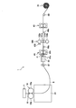
- FIG. 2 is an explanatory diagram showing a schematic configuration of a manufacturing process of a slab (thin slab) according to the present embodiment.
- the continuous casting facility 1 includes, for example, a tundish (storage device) T, a twin drum continuous casting device 10, an antioxidant device 20, a cooling device 30, 1 pinch roll device 40, in-line mill 100, second pinch roll device 60, and winding device 70.
- the twin-drum continuous casting apparatus 10 includes, for example, a pair of cooling drums 10a and 10b and a pair of side weirs (not shown) arranged on both sides in the axial direction of the pair of cooling drums 10a and 10b. And).
- the pair of cooling drums 10 a and 10 b and the side dam constitute a molten metal storage unit 15 that stores the molten metal supplied from the tundish T.
- the twin-drum type continuous casting apparatus 10 casts a slab from the molten metal stored in the molten metal storage unit 15 while rotating the pair of cooling drums 10a and 10b in opposite directions.
- the pair of cooling drums 10a and 10b includes a first cooling drum 10a and a second cooling drum 10b.
- the first cooling drum 10a and the second cooling drum 10b have a concave profile in which the center in the axial direction is slightly depressed.
- the 1st cooling drum 10a and the 2nd cooling drum 10b are comprised so that adjustment of the space
- the 1st cooling drum 10a and the 2nd cooling drum 10b are comprised so that a cooling medium (for example, cooling water) can distribute
- the cooling drums 10a and 10b can be cooled by circulating the cooling medium inside the cooling drums 10a and 10b. Further, dimples are formed on the surfaces of the cooling drums 10a and 10b.
- the first cooling drum 10a and the second cooling drum 10b are set such that, for example, the outer diameter is 800 mm, the drum body length (width) is 1500 mm, and the plate crown of the slab S in a steady state is 30 ⁇ m.
- the dimples may have a length in the rolling direction of 1.0 mm to 2.0 mm and a depth of 50 ⁇ m to 100 ⁇ m. That is, the length in the rolling direction of the protrusions formed by the dimples may be 1.0 mm to 2.0 mm, and the height of the protrusions formed by the dimples may be not less than 50 ⁇ m and not more than 100 ⁇ m.
- the outer diameters, drum body lengths (widths), and dimple shapes of the pair of cooling drums 10a and 10b are not limited thereto.
- a dummy sheet (not shown) is connected to the tip of the slab S, and casting is started.
- a dummy bar (not shown) having a thickness larger than that of the slab S is provided at the tip of the dummy sheet, and the dummy sheet is guided by the dummy bar.
- a hump (not shown) thicker than the plate thickness of the slab S is formed at the connection portion between the tip of the slab S and the dummy sheet.
- a rolling start method called a flying touch is performed in which rolling is started after the hump passes through the in-line mill 100.
- the antioxidant 20 is a device that performs a process for preventing the surface of the slab S immediately after casting from oxidizing and generating scale.
- the amount of oxygen can be adjusted by nitrogen gas. It is preferable to apply the antioxidant 20 as necessary in consideration of the steel type of the slab S to be cast.
- the cooling device 30 is a device that is disposed on the downstream side of the twin-drum type continuous casting device 10 and cools the slab S that has been subjected to an antioxidant treatment on the surface by the antioxidant device 20.
- the cooling device 30 includes, for example, a plurality of spray nozzles (not shown), and ejects cooling water from the spray nozzle to the surface (upper surface and lower surface) of the slab S according to the steel type. Cooling.
- a pair of feed rolls 87 may be arranged between the antioxidant device 20 and the cooling device 30.
- the pair of feed rolls 87 does not roll the slab S, but sandwiches the slab S by a pressing device (not shown), and the slab S between the pair of cooling drums 10a and 10b and the feed roll 87. While measuring the loop length, a conveying force in the horizontal direction is applied to the slab S so that the loop length is constant.
- the feed roll 87 is constituted by a pair of rolls having a roll diameter of 200 mm and a roll body length (width) of 2000 mm, for example.
- the first pinch roll device 40 is a pinch roll device disposed on the entry side of the inline mill 100.
- the first pinch roll device 40 does not roll the slab S, but an upper pinch roll 40a and a lower pinch roll 40b, a housing, a roll chock, a rolling load detection device, and a pressing device (first pinch roll device). None of them except 40 is shown.).
- Each of the upper pinch roll 40a and the lower pinch roll 40b has a hollow channel formed therein, and is configured to allow a cooling medium (for example, cooling water) to flow therethrough.
- the first pinch roll device 40 can be cooled by circulating the cooling medium.
- the upper pinch roll 40a and the lower pinch roll 40b may have, for example, a roll diameter of 400 mm and a roll trunk length (width) of 2000 mm.
- the upper pinch roll 40a and the lower pinch roll 40b are disposed via a roll chock in the housing, and are rotationally driven by a motor (not shown).
- the upper pinch roll 40a is connected to a pass line adjusting device (not shown) via an upper rolling load detection device (not shown), and the lower pinch roll 40b is a pressing device (not shown). .).
- the pressing load applied to the upper pinch roll 40a and the lower pinch roll 40b is detected.
- Tension is generated in the slab S between the first pinch roll device 40 and the inline mill 100.
- the slab S in the pair of pinch rolls 40a and 40b and the inline mill 100 is set so that the tension generated in the slab S between the first pinch roll device 40 and the inline mill 100 becomes a preset tension.
- the moving speed is controlled.
- the tension of the slab S between the first pinch roll device 40 and the inline mill 100 is detected by a tension roll 88a.
- a position detection device 41 that detects the position of the slab may be provided on the upstream side of the first pinch roll.
- the in-line mill 100 is a rolling device that is arranged on the downstream side of the cooling device 30 and the first pinch roll device 40 and rolls the slab S in one pass so that the slab S has a desired thickness.
- the in-line mill 100 is configured as a quadruple rolling mill. That is, the in-line mill 100 includes a pair of work rolls 101a and 101b and backup rolls 102a and 102b disposed above and below the work rolls 101a and 101b.
- “one-pass rolling” means that the slab S having the thickness of the slab S that has passed through the continuous casting apparatus 10 is rolled once in the in-line mill 100 to obtain a desired thickness on the outlet side of the in-line mill. It means that it is plastically deformed to have.
- the in-line mill 100 can roll the slab S to a desired thickness without impairing productivity by rolling the slab S at a reduction rate of 10% or more for one pass.
- the rolling reduction is preferably 15% or more, and more preferably 20% or more.
- the upper limit of the rolling reduction is not particularly limited, but if the rolling reduction in one-pass rolling is excessively high, the protrusion may be bent even if the friction coefficient is controlled as described later. is there. Therefore, the upper limit of the rolling reduction is preferably 40% or less, and more preferably 35% or less.
- H (mm) is the plate thickness of the slab S before rolling
- h (mm) is the plate thickness of the slab S after rolling.
- the in-line mill 100 may use, for example, work rolls 101a and 101b having a roll diameter of 400 mm and backup rolls 102a and 102b having a roll diameter of 1200 mm.
- the length of each roll may be the same, for example, 2000 mm.
- the in-line mill 100 is equipped with equipment for supplying lubricating oil to at least one of the work roll and the slab, and the lubrication conditions and the like can be controlled. Detailed description regarding the supply of the lubricating oil will be described later.
- the second pinch roll device 60 is disposed on the exit side of the inline mill 100. Similarly to the first pinch roll device 40, the second pinch roll device 60 does not roll the slab S, but an upper pinch roll and a lower pinch roll, a rolling load detection device, a pressing device (second device). These are not shown except for the pinch roll 60.).
- Each of the upper pinch roll and the lower pinch roll has a hollow channel formed therein, and is configured to allow a cooling medium (for example, cooling water) to flow therethrough.
- the pinch roll can be cooled by circulating the cooling medium.
- the upper pinch roll and the lower pinch roll may have a roll diameter of 400 mm and a roll body length (width) of 2000 mm.
- the upper pinch roll and the lower pinch roll are arranged via a roll chock in the housing, and are rotationally driven by a motor (not shown).
- a tension roll 88 b is disposed between the inline mill 100 and the second pinch roll device 60.
- the winding device 70 is a device that is disposed on the downstream side of the inline mill 100 and the second pinch roll device 60 and winds the slab S into a coil shape.
- a deflector roll 89 is disposed between the second pinch roll device 60 and the winding device 70.
- control of the lubrication conditions for preventing the slab protrusion from being bent by controlling the lubrication conditions during rolling of the slab by the in-line mill will be described in detail.
- an example of controlling the supply amount of the lubricating oil will be described as an example of the control of the lubrication conditions.
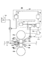
- FIG. 3 is a detailed view of the in-line mill 100.
- the in-line mill 100 includes a pair of work rolls 101a and 101b and backup rolls 102a and 102b disposed above and below the work rolls 101a and 101b.
- Cooling water supply nozzles 103a, 103b, 104a, 104b are provided before and after the in-line mill 100 in the rolling direction, and cooling water is supplied to the work rolls 101a, 101b.
- the work rolls 101a and 101b are cooled by the cooling water.
- draining plates 106a, 106b, 107a, 107b are provided between the cooling water supply nozzles 103a, 103b, 104a, 104b and the slab S so that the cooling water does not reach the slab.
- Lubricating oil supply nozzles 105 a and 105 b for supplying lubricating oil to at least one of the work roll surface and the cast piece are installed between the draining plates 107 a and 107 b installed on the entry side of the in-line mill 100 and the cast piece S.
- the lubricating conditions are controlled by controlling the amount of lubricating oil supplied by these lubricating oil supply nozzles 105a and 105b.
- Lubricating oil supplied from the lubricating oil supply nozzles 105 a and 105 b is stored in the lubricating oil tank 115.
- the lubricating oil may be, for example, an emulsion lubricating oil prepared by heating and stirring water mixed in the lubricating oil tank 115 and rolling lubricating oil.
- the produced emulsion lubricating oil is fed by the pump P and supplied from the lubricating oil supply nozzles 105a and 105b through the piping.
- the lubricating oil may be only the rolling lubricating oil without including a diluent such as water. Moreover, it is good also as emulsion lubricating oil by storing warm water and rolling lubricating oil in a separate tank, supplying separately into piping from each storage location, and mixing and shearing both after that.
- the lubricating oil itself may be sprayed onto the work roll like air atomization. Moreover, you may supply solid lubricating oil with respect to a slab.
- the casting on the rolling mill input side is changed even if the supply amount of the lubricating oil supply nozzles 105a and 105b is changed.
- the temperature of the slab may be controlled by cooling control of the cooling device 30 so that the temperature of the piece does not change.
- the continuous casting equipment in which the cooling water supply nozzles 104a and 104b, the draining plates 106a and 106b, and the lubricating oil supply nozzles 105a and 105b are provided on the rolling mill entrance side is shown. 104b and draining plates 106a and 106b are not essential and may be omitted.
- a measurement device 110 that measures information necessary for controlling the lubrication conditions and a lubrication control device 120 that controls the lubrication conditions of the in-line mill 100 are provided.
- the measuring device 110 has a load cell 111 and a plate speedometer 112. In the measuring apparatus 110, various values necessary for controlling the lubrication conditions are measured.
- the load cell 111 is disposed in a roll chock of the upper backup roll 102a and measures a rolling load.
- the plate speed meter 112 is provided on the exit side of the rolling mill and measures the plate speed (V 0 ) of the slab.
- the plate speedometer 112 may use, for example, a non-contact type speed measuring device.
- the lubrication control device 120 includes a work roll (WR) speed converter 121, a calculator 122, a friction coefficient calculator 123, and a friction coefficient adjuster 124.
- the lubrication control device 120 calculates the friction coefficient ⁇ based on the value detected and calculated by the measurement device 110 and controls the lubrication condition.
- the WR speed converter 121 calculates the work roll speed (V R ) from the number of rotations of the motor 116 using the ratio of the speed reducer (not shown) and the work roll diameter.
- the calculator 122 calculates the advanced rate (fs) from the slab plate speed and the work roll speed.
- the calculator 122 calculates the advanced rate (fs) from the following equation (1). That is, the calculator 122 calculates the advanced rate (fs) based on the plate speed (V o ) and the work roll speed (V R ).
- f S (V O / V R ⁇ 1) ⁇ 100 (1)
- the friction coefficient calculator 123 calculates the friction coefficient ⁇ based on the advanced rate (fs) calculated by the calculator 122 and the rolling load. Then, the friction coefficient adjuster 124 calculates the supply amount of lubricating oil necessary for controlling the friction coefficient ⁇ using the calculated friction coefficient ⁇ . The friction coefficient adjuster 124 further controls the supply of the lubricating oil supplied to the in-line mill 100 by controlling the pump P so that the amount of the lubricating oil supplied to control the calculated friction coefficient ⁇ is obtained. . In this way, the lubrication conditions are controlled using the measuring device 110 and the lubrication control device 120.
- the bending of the protrusion is caused by deformation in the roll bite that occurs during rolling of the slab, and is greatly affected by the shearing force of the surface layer in the roll bite.
- the shearing force is calculated by multiplying the compressive stress (rolling load) in the roll bite and the friction coefficient ⁇ .
- the rolling is basically performed without changing the conditions such as the steel type, rolling speed, and tension, and the rolling reduction is the same. Therefore, although the values of these parameters cannot be changed, the shear force of the surface layer in the roll bite in the in-line mill can be changed by adjusting the friction coefficient ⁇ . Therefore, the inventor of the present application examined an appropriate range of the friction coefficient ⁇ during rolling that can prevent the slab protrusion from folding.
- the width of the protrusions and the height of the protrusions were changed to verify the state of the slab protrusions after rolling.
- the results will be described with reference to FIGS.
- the width A of the protrusion D was changed to 1 to 3 mm and the height B was changed to 50 to 200 ⁇ m to set the shape conditions of the five protrusions.
- the slabs on which these protrusions were formed were rolled by changing the friction coefficient ⁇ between 0.10 and 0.33.
- the friction coefficient ⁇ is a value calculated using a rolling analysis model based on the rolling conditions shown below.
- an equation of a deformation resistance model based on Orowan theory and an approximation formula of Shida was used as a rolling analysis model.
- the rolling of the slab in this verification was performed in the manufacturing process of the slab having the same configuration as in FIG.
- the slab used was a plain steel with a plate thickness of 2 mm and a plate width of 1200 mm.
- the acceleration rate of the cooling drum from the start of casting was 150 m / min / 30 seconds, and the rotational speed of the cooling drum in the steady state was 150 m / min.
- the initial profile of the cooling drum was processed so that the crown of the slab became 43 ⁇ m in a steady state.
- the slab rolling in this verification was performed with ordinary steel, the steel type to be rolled is not limited to ordinary steel.
- the in-line mill 100 a slab having a plate temperature of 1000 ° C. was rolled in one pass at a reduction rate of 30%, and the thickness of the slab on the inline mill exit side was set to 1.4 mm. Rolling in the in-line mill 100 was started after a dummy sheet passed through the in-line mill 100 and the plate crown of the slab became 150 ⁇ m or less. In this verification, rolling in the in-line mill 100 was started 15 seconds after the start of casting.
- a lubricating oil (melting point 0 ° C.) based on a synthetic ester (hindered complex ester) was supplied by an air atomization method.
- FIG. 5 shows the evaluation of the steel sheet under five conditions in which the width A and the height B of the protrusions are changed in the friction coefficient range of 0.10 to 0.33. Evaluation was shown by x in the steel plate which was unstable at the time of rolling, or the bending of the protrusion generate
- the protrusion D was folded when the friction coefficient ⁇ exceeded 0.25 regardless of the shape of the protrusion. If the friction coefficient ⁇ is not less than 0.15 and not more than 0.25, the protrusion D disappears and folds occur even if the width A and height B of the protrusion are in any shape of the conditions 1 to 5. There was no. When the friction coefficient ⁇ was less than 0.15, the protrusions disappeared, but the friction coefficient was small, and slipping occurred during rolling due to excessive lubrication, resulting in unstable rolling. In addition, excessive lubrication may occur due to an excessive supply amount of the lubricating oil.
- the basic unit of the lubricating oil deteriorates and the production cost of the slab increases.
- the friction coefficient ⁇ exceeded 0.25, the protrusion D was bent. From these results, the specified range of the friction coefficient ⁇ is set to a range of 0.15 to 0.25.
- the specified range of the friction coefficient ⁇ is set to 0.15 or more and 0.25 or less to control the lubrication conditions during rolling, thereby preventing the protrusions of the slab from being folded.
- the lubricating oil is not supplied, and water lubrication that also serves as roll cooling has been performed.
- the friction coefficient is high.
- the friction coefficient is calculated using the measured value of the rolling load and the advanced rate using the deformation resistance model expression by the approximate expression of the Owanan theory Shida as the rolling analysis model, the friction coefficient is 0.3. The range was about 0.4.
- FIG. 6 is a flowchart showing a lubrication condition control method according to this embodiment.
- the friction coefficient ⁇ can be calculated using a rolling analysis model.
- the value of the friction coefficient ⁇ is slightly different depending on the rolling analysis model used.
- the friction coefficient ⁇ is calculated using, for example, the Orowan theory disclosed in Non-Patent Document 1.
- Shida's approximate equation also disclosed in Non-Patent Document 1 is used.
- the roll diameter, tension, rolling load, sheet thickness, rolling speed, etc. can be measured at the time of rolling and can be handled as known numbers, so the unknown numbers are the friction coefficient ⁇ and the deformation resistance. Therefore, if two independent values are used, the friction coefficient and the deformation resistance can be calculated as a coupled problem. Therefore, for example, in the rolling analysis model that substitutes the measured values of rolling load and advanced rate and the rolling analysis model that assigns the calculated values of rolling load and advanced rate, the deformation resistance and friction coefficient are changed so that both values match. Thus, the friction coefficient ⁇ can be obtained by performing the calculation.
- the Owanan theory and the equation of the deformation resistance model based on the approximation formula of Shida were used as the rolling analysis model.
- the present invention is not limited to this example, and by using another rolling analysis model, the friction coefficient ⁇ can be calculated. You may ask for it.
- the approximate expression for calculating the friction coefficient ⁇ can be expressed as the following expression (2) using the advanced rate (f S ) and the rolling load (p). If necessary, a table may be formed according to the steel type, plate thickness, and rolling temperature.
- the constants a, b, and c of the approximate expression represented by Expression (2) may be obtained by multiple regression analysis.
- the friction coefficient ⁇ can be obtained using only the advanced rate (f S ) and rolling load (p) measured at the time of rolling.
- the calculation load can be reduced as compared with the method of calculating the friction coefficient ⁇ obtained by substituting.
- the constants a, b, and c in the approximate expression (3) may be obtained using, for example, multiple regression analysis.
- the lubricating oil supply amount Q refers to the net lubricating oil supply amount supplied to at least one unit surface area of the work roll or slab. In the case of emulsion lubricating oil, dilution of mixed water or the like Solvent is not included.
- step S100 in the target facility, the supply amount of the lubricating oil is changed in a steady state, and the rolling load (p) at each lubricating oil supply amount is acquired by the load cell, and the plate speed ( The advance rate (fs) is obtained based on V o ) and the work roll speed (V R ). Then, the friction coefficient calculator 123 calculates the friction coefficient at each lubricating oil supply amount from the rolling load and the advanced rate using, for example, the above equation (2). When the relationship between the plurality of lubricating oil supply amounts and the friction coefficient is acquired, the relationship between the lubricating oil supply amount and the friction coefficient ⁇ represented by, for example, the approximate expression (3) is acquired using these data. Is done. Based on the relationship between the lubricant supply amount obtained in step S100 and the friction coefficient ⁇ , the lubricant supply amount in the in-line mill 100 in actual operation is controlled.
- the rolling load is detected by the load cell 111 arranged in the roll chock of the upper backup roll (step S102).
- the WR speed converter 121 detects the rotation speed of the motor 116 that rotates the work rolls 101a and 101b, and calculates the work roll speed based on the rotation speed of the motor 116, the ratio of the speed reducer, and the work roll diameter.
- the plate speed of the slab S is detected by the plate speed meter 112 arranged on the exit side of the in-line mill 100 (step S106). In FIG. 6, although shown in the order of step S102, step S104, and step S106, these processes are performed in parallel.
- the advance rate is calculated by the calculator 122 using the work roll speed calculated in step S104 and the plate speed measured in step S106 (step S108).
- the friction coefficient ⁇ is calculated by the friction coefficient calculator 123 based on the detected and calculated rolling load and the advanced rate (step S110).
- the friction coefficient ⁇ may be calculated using, for example, the above equation (2).
- the lubrication oil supply amount is calculated by the friction coefficient adjuster 124.
- the friction coefficient adjuster 124 first obtains a difference ⁇ between the friction coefficient ⁇ calculated in step S110 and the target friction coefficient ⁇ aim (step S112).
- the target friction coefficient ⁇ aim is set to a value in the range of 0.15 to 0.25.
- the target friction coefficient ⁇ aim may be set from a range in which the specified range is further narrowed.
- the target friction coefficient ⁇ aim may be set to 0.20, for example.
- the friction coefficient adjuster 124 adjusts the lubricating oil corresponding to the difference ⁇ calculated in step S112 based on the relationship between the known friction coefficient ⁇ acquired in advance in step S100 and the lubricating oil supply amount Q.
- An amount (hereinafter also referred to as “lubricating oil adjustment amount ⁇ Q”) is calculated (step S114).
- the lubricant supply amount (ie, lubricant supply amount) ⁇ Q to be adjusted is calculated based on the difference ⁇ between the friction coefficient ⁇ calculated in step S112 and the target friction coefficient ⁇ aim .
- the friction coefficient adjuster 124 adjusts the currently set lubricating oil supply amount Q by the lubricating oil adjustment amount ⁇ Q corresponding to the difference ⁇ between the friction coefficient ⁇ and the target friction coefficient ⁇ aim, and the lubricating oil supply amount Change to Q + ⁇ Q (step S116).
- the friction coefficient adjuster 124 controls the pump P so that the amount of lubricating oil supplied by the lubricating oil supply nozzles 105a and 105b becomes the lubricating oil supply amount Q 0 + ⁇ Q. Thereby, the friction coefficient ⁇ is set to the target friction coefficient ⁇ aim .
- steps S102 to S116 are repeatedly performed during the rolling of the slab (S118).
- step S118 / Yes the control of the lubrication conditions in the in-line mill 100 is finished.
- step S118 / No the process starts again from step 202 in which the rolling load is detected by the load cell, and the process up to step S116 in which the lubricant supply amount is adjusted is repeated. Done.
- the method for controlling the lubrication conditions according to the present embodiment has been described.
- the supply amount of the lubricating oil to the work roll has been described.
- the lubrication condition is not limited to the supply amount of the lubricating oil as long as the friction coefficient ⁇ can be changed.
- the lubrication conditions may be controlled by other methods such as the type of the lubricant, the ratio of the lubricant and water in the emulsion lubricant, and the supply temperature of the lubricant.
- a synthetic ester or a synthetic ester mixed with vegetable oil may be used as a base oil.
- This example was performed in the manufacturing process of a slab having the same configuration as in FIG.
- ordinary steel having a plate thickness of 2 mm and a plate width of 1200 mm was used.
- the acceleration rate of the cooling drum from the start of casting was 150 m / min / 30 seconds, and the rotational speed of the cooling drum in the steady state was 150 m / min.
- the initial profile of the cooling drum was processed so that the crown of the slab became 43 ⁇ m in a steady state.
- the slab was rolled with ordinary steel, but the steel type to be rolled is not limited to ordinary steel.
- a slab having a plate temperature of 1000 ° C. was rolled in one pass at a reduction ratio of 30%, and the thickness of the slab on the inline mill exit side was set to 1.4 mm.
- Rolling in the in-line mill was started after the dummy sheet passed through the in-line mill and the plate crown of the slab became 150 ⁇ m or less. In this verification, rolling in an in-line mill was started 15 seconds after the start of casting.
- a lubricating oil (melting point 0 ° C.) based on a synthetic ester (hindered complex ester) was supplied by an air atomization method.
- the friction coefficient ⁇ was obtained by measuring the rolling load (p) and the advanced rate (fs) at the time of rolling and using the above formula (2).
- the lubricating oil can be obtained from the above formula (4).
- the adjustment amount ⁇ Q was calculated, the supply amount of the lubricating oil was controlled, and the supply amount of the lubricating oil was controlled with the target friction coefficient ⁇ aim 0.21. As a result, the slab was rolled so that the friction coefficient ⁇ was in the range of 0.19 to 0.23.
- the slab after rolling was pickled in the pickling step, and then further subjected to multi-pass rolling to a sheet thickness of 0.2 mm with a Sendzimer rolling mill having a diameter of 60 mm. In the pickling process, 10 ⁇ m of cutting was performed.
- the same rolling as in the example was performed without supplying the lubricating oil, and then the pickling in the pickling process, and then the same rolling as in the example was performed.
- the friction coefficient ⁇ at this time was 0.38 when calculated using the Owanan theory and the deformation resistance model equation by Shida's approximation as the rolling analysis model.
- 10 ⁇ m was cut.
- the rolling of 50 coils was performed in combination with the example and the comparative example, and the surface of the cast slab after rolling with a Zenzimer rolling mill was observed. As a result of surface observation, no surface defects were confirmed in the slab in the examples. On the other hand, in the comparative example, surface defects were confirmed in the slab. When the same rolling was performed again under the conditions of the comparative example, it was confirmed that 30 ⁇ m of cutting was necessary in the pickling process in order to eliminate surface defects. That is, in the comparative example, it was confirmed that it was necessary to perform the cutting of the slab three times as much as the example. From these results, by appropriately controlling the range of the coefficient of friction ⁇ when rolling the slab, it is possible to prevent the occurrence of folding of the protrusions, and further to improve the pickling efficiency by a factor of 3 compared to the prior art. all right.
- ADVANTAGE OF THE INVENTION According to this invention, it becomes possible to prevent the folding of the protrusion which generate
- a method for producing a slab and a continuous casting facility can be provided.
Abstract
Description
本願は、2018年3月2日に、日本に出願された特願2018-037945号に基づき優先権を主張し、その内容をここに援用する。 The present invention relates to a slab manufacturing method and continuous casting equipment.
This application claims priority on March 2, 2018 based on Japanese Patent Application No. 2018-037945 filed in Japan, the contents of which are incorporated herein by reference.
(2)上記(1)に記載の鋳片の製造方法では、前記突起の高さが50μm以上100μm以下であってもよい。
(3)上記(1)又は(2)に記載の鋳片の製造方法では、前記潤滑条件は、前記ワークロールまたは鋳造された前記鋳片の少なくとも一方に供給される潤滑油の供給量であってもよい。
(4)本発明の第二の態様は、表面にディンプルが形成された一対の冷却ドラムと一対のサイド堰とによって金属溶湯貯留部を形成し、前記一対の冷却ドラムを回転させながら前記金属溶湯貯留部に貯留された金属溶湯から前記ディンプルにより形成された突起を有する鋳片を鋳造する双ドラム式連続鋳造装置と、前記双ドラム式連続鋳造装置の下流側に配置され、前記鋳片を冷却する冷却装置と、前記冷却装置の下流側に配置され、前記鋳片をワークロールにて圧下率10%以上の1パス圧延を行うインラインミルと、前記インラインミルの下流側に配置され、前記鋳片をコイル状に巻取る巻取装置と、前記インラインミルにより圧延される前記鋳片の圧延荷重及び先進率を実測する測定装置と、圧延解析モデルを用いて、前記圧延荷重及び先進率の実測値から摩擦係数を算出し、前記摩擦係数が所定の範囲内に入るように、前記鋳片の圧延時の潤滑条件を制御する潤滑制御装置と、を備え、前記圧延解析モデルとしてOrowan理論と志田の近似式による変形抵抗モデルの式とを用いて前記圧延荷重及び先進率の実測値から前記摩擦係数を算出した場合に、前記所定の範囲が0.15以上0.25以下である連続鋳造設備である。
(5)上記(4)に記載の連続鋳造設備では、前記突起の高さが50μm以上100μm以下であってもよい。
(6)上記(4)又は(5)に記載の連続鋳造設備では、前記潤滑制御装置は、前記摩擦係数を制御するために必要な潤滑油の供給量を計算するとともに、前記インラインミルに供給する潤滑油の供給制御を行う摩擦係数調節器を備えてもよい。 (1) According to a first aspect of the present invention, a molten metal storage section is formed by a pair of cooling drums having dimples formed on the surface and a pair of side weirs, and the molten metal is rotated while the pair of cooling drums is rotated. A twin-drum type continuous casting apparatus that casts a slab having protrusions formed by the dimples from the molten metal stored in the storage unit, and a downstream side of the twin-drum type continuous casting apparatus, and cools the slab A cooling device that is disposed downstream of the cooling device, an in-line mill that performs one-pass rolling of the slab with a work roll of 10% or more by a work roll, and a downstream of the in-line mill, A method for producing a slab by a continuous casting facility comprising a coiling device for winding the slab into a coil shape, wherein a rolling load and an advanced rate when the slab is rolled using a rolling analysis model The friction coefficient is calculated from the value, the lubrication conditions during rolling of the slab are controlled so that the friction coefficient falls within a predetermined range, and the deformation resistance model based on the Owanan theory and the approximate expression of Shida as the rolling analysis model The predetermined range is 0.15 or more and 0.25 or less when the coefficient of friction is calculated from the measured values of the rolling load and the advanced rate using the following formula.
(2) In the slab manufacturing method according to (1) above, the height of the protrusion may be not less than 50 μm and not more than 100 μm.
(3) In the method for manufacturing a slab according to (1) or (2), the lubrication condition is a supply amount of lubricating oil supplied to at least one of the work roll or the cast slab. May be.
(4) According to a second aspect of the present invention, a molten metal reservoir is formed by a pair of cooling drums having dimples formed on the surface and a pair of side weirs, and the molten metal is rotated while rotating the pair of cooling drums. A twin-drum type continuous casting apparatus that casts a slab having protrusions formed by the dimples from the molten metal stored in the storage unit, and a downstream side of the twin-drum type continuous casting apparatus, and cools the slab A cooling device that is disposed downstream of the cooling device, an in-line mill that performs one-pass rolling of the slab with a work roll of 10% or more by a work roll, and a downstream of the in-line mill, Using a winding device for winding the piece into a coil, a measuring device for actually measuring the rolling load and the advanced rate of the slab rolled by the in-line mill, and a rolling analysis model, the rolling load and A friction coefficient is calculated from the measured value of the advanced rate, and a lubrication control device that controls the lubrication conditions during rolling of the slab so that the friction coefficient falls within a predetermined range, and as the rolling analysis model When the friction coefficient is calculated from the measured values of the rolling load and the advanced rate using the Owanan theory and the equation of deformation resistance model by Shida's approximate expression, the predetermined range is 0.15 or more and 0.25 or less. It is a continuous casting facility.
(5) In the continuous casting equipment described in (4) above, the height of the protrusion may be not less than 50 μm and not more than 100 μm.
(6) In the continuous casting facility according to (4) or (5), the lubrication control device calculates a supply amount of lubricating oil necessary for controlling the friction coefficient, and supplies the lubrication oil to the in-line mill. A friction coefficient adjuster that controls supply of lubricating oil may be provided.
本発明者は、双ドラム式連続鋳造設備により製造されディンプルにより形成された突起を有する鋳片をインラインミルで圧延する際に、突起の折れ込みを防止することを可能にする鋳片の製造方法を鋭意研究した。その結果、鋳片をインラインミルで圧延する時に、圧延解析モデルを用いて、圧延荷重及び先進率の実測値から摩擦係数を算出し、摩擦係数が所定の範囲内に入るように、鋳片の圧延時の潤滑条件を制御する方法を想到した。摩擦係数が所定の範囲内に入るように、鋳片の潤滑条件を制御することにより、生産性を損なうことなく、鋳片の表面に形成された突起の折れ込みを防止できる。 <1. Overview>
The present inventor has disclosed a method for producing a slab that can prevent the protrusion from being folded when an in-line mill is used to roll a slab having protrusions that are manufactured by a twin-drum type continuous casting facility and formed by dimples. I have studied earnestly. As a result, when rolling the slab with an in-line mill, the rolling analysis model is used to calculate the friction coefficient from the measured values of the rolling load and the advanced rate, so that the friction coefficient falls within a predetermined range. A method for controlling the lubrication conditions during rolling was conceived. By controlling the lubrication conditions of the slab so that the friction coefficient falls within a predetermined range, it is possible to prevent the protrusions formed on the surface of the slab from being bent without impairing the productivity.
まず、図2を参照して、本発明の実施形態に係る鋳片を製造する製造工程の概要を説明する。図2は、本実施形態に係る鋳片(薄肉鋳片)の製造工程の概略構成を示す説明図である。 <2. Manufacturing process>
First, with reference to FIG. 2, the outline | summary of the manufacturing process which manufactures the slab which concerns on embodiment of this invention is demonstrated. FIG. 2 is an explanatory diagram showing a schematic configuration of a manufacturing process of a slab (thin slab) according to the present embodiment.
双ドラム式連続鋳造装置10は、図2に示すように、例えば、一対の冷却ドラム10a、10bと、一対の冷却ドラム10a、10bの軸方向両側に配置された一対のサイド堰(図示せず。)と、を備える。一対の冷却ドラム10a、10bとサイド堰とは、タンディッシュTから供給される溶融金属を貯留する金属溶湯貯留部15を構成している。双ドラム式連続鋳造装置10は、一対の冷却ドラム10a、10bを互いに逆方向に回転させながら、金属溶湯貯留部15に貯留された金属溶湯から鋳片を鋳造する。 (Double drum type continuous casting machine)
As shown in FIG. 2, the twin-drum
酸化防止装置20は、鋳造直後の鋳片Sの表面が酸化してスケールが発生することを防止するための処理を行う装置である。酸化防止装置20内では、例えば、窒素ガスによって酸素量を調整することが可能である。酸化防止装置20は、鋳造する鋳片Sの鋼種等を考慮し、必要に応じて適用することが好ましい。 (Antioxidation equipment)
The
冷却装置30は、双ドラム式連続鋳造装置10の下流側に配置され、酸化防止装置20により酸化防止処理が表面に施された鋳片Sを冷却する装置である。冷却装置30は、例えば、複数のスプレーノズル(図示せず。)を備え、鋼種に応じてスプレーノズルから鋳片Sの表面(上面及び下面)に対して冷却水を噴出し、鋳片Sを冷却する。 (Cooling system)
The
第1のピンチロール装置40は、インラインミル100の入側に配置されるピンチロール装置である。第1のピンチロール装置40は鋳片Sを圧延するものではなく、上ピンチロール40a及び下ピンチロール40bと、ハウジングと、ロールチョックと、圧延荷重検出装置と、押付装置(第1のピンチロール装置40以外はいずれも図示せず。)と、を備えている。上ピンチロール40a及び下ピンチロール40bは、それぞれ内部に中空流路が形成されており、冷却媒体(例えば、冷却水)が流通可能に構成されている。冷却媒体を流通させることにより、第1のピンチロール装置40を冷却することができる。 (First pinch roll device)
The first
インラインミル100は、冷却装置30及び第1のピンチロール装置40の下流側に配置され、鋳片Sを1パス圧延して鋳片Sを所望の板厚にする圧延装置である。本実施形態では、インラインミル100は4重圧延機として構成されている。すなわち、インラインミル100は、一対のワークロール101a、101bと、ワークロール101a、101bの上下に配置されたバックアップロール102a、102bとを備える。尚、「1パス圧延」とは、連続鋳造装置10を経た鋳片Sの板厚を有する鋳片Sを、インラインミル100での1回の圧延によって、インラインミル出側で所望の板厚を有するように塑性変形させることを意味する。 (Inline mill)
The in-
圧下率の上限は特に限定されるべきものではないが、1パス圧延での圧下率が過剰に高い場合には、後述のように摩擦係数を制御しても突起の折れ込みが発生する場合がある。従って、圧下率の上限は40%以下であることが好ましく、35%以下であることが更に好ましい。
尚、圧下率(r)は次式で定義される。
r={(H-h)/H}×100 (%)
ここで、H(mm)は圧延前の鋳片Sの板厚であり、h(mm)は圧延後の鋳片Sの板厚である。 The in-
The upper limit of the rolling reduction is not particularly limited, but if the rolling reduction in one-pass rolling is excessively high, the protrusion may be bent even if the friction coefficient is controlled as described later. is there. Therefore, the upper limit of the rolling reduction is preferably 40% or less, and more preferably 35% or less.
The rolling reduction (r) is defined by the following equation.
r = {(H−h) / H} × 100 (%)
Here, H (mm) is the plate thickness of the slab S before rolling, and h (mm) is the plate thickness of the slab S after rolling.
第2のピンチロール装置60は、インラインミル100の出側に配置されている。第2のピンチロール装置60は、第1のピンチロール装置40と同様に、鋳片Sを圧延するものではなく、上ピンチロール及び下ピンチロールと、圧延荷重検出装置と、押付装置(第2のピンチロール60以外は、いずれも図示せず。)と、を備えている。上ピンチロール及び下ピンチロールは、それぞれ内部に中空流路が形成されており、冷却媒体(例えば、冷却水)が流通可能に構成されている。冷却媒体を流通させることにより、ピンチロールを冷却することができる。上ピンチロール及び下ピンチロールは、例えば、ロール径400mm、ロール胴長(幅)2000mmとしてもよい。また、上ピンチロール及び下ピンチロールは、ハウジング内のロールチョックを介して配置されており、モータ(図示せず。)によって回転駆動される。インラインミル100と第2のピンチロール装置60との間には、テンションロール88bが配置されている。 (Second pinch roll device)
The second
巻取装置70は、インラインミル100と第2のピンチロール装置60の下流側に配置され、鋳片Sをコイル状に巻き取る装置である。第2のピンチロール装置60と巻取装置70との間には、デフレクターロール89が配置されている。 (Winding device)
The winding
突起のある鋳片をインラインミルにて圧延する場合、突起の折れ込みが生じると表面欠陥の発生につながる。そこで、本願発明者は、突起の折れ込みの発生を防止するために検討した結果、インラインミルでの鋳片とワークロールとの間の摩擦係数に応じて突起の折れ込みの発生の有無が変化するとの知見を得た。そして、かかる知見に基づき、インラインミルによる圧延時の潤滑条件を制御することで鋳片とワークロールとの間の摩擦係数を制御し、突起の折れ込みの発生を防止することを想到した。以下、インラインミルによる鋳片の圧延時の潤滑条件の制御により鋳片の突起の折れ込みを発生させないようにするための潤滑条件の制御について、詳細に説明する。なお、ここでは、潤滑条件の制御の一例として、潤滑油の供給量を制御する例を挙げて説明する。 <3. Control of equipment configuration and lubrication conditions>
When rolling a cast slab having a protrusion with an in-line mill, if the protrusion is bent, it will cause a surface defect. Therefore, the inventors of the present application have studied to prevent the occurrence of the folding of the projection, and as a result, the presence or absence of the folding of the projection changes depending on the friction coefficient between the slab and the work roll in the in-line mill. I got the knowledge. Based on this knowledge, the inventors have conceived that the friction coefficient between the slab and the work roll is controlled by controlling the lubrication condition during rolling by the in-line mill, and the occurrence of the folding of the protrusion is prevented. Hereinafter, control of the lubrication conditions for preventing the slab protrusion from being bent by controlling the lubrication conditions during rolling of the slab by the in-line mill will be described in detail. Here, an example of controlling the supply amount of the lubricating oil will be described as an example of the control of the lubrication conditions.
インラインミル100による圧延時の潤滑条件の制御を説明するにあたり、図3を参照して、本実施形態におけるインラインミル100の詳細を説明する。図3は、インラインミル100の詳細図である。 (3-1. Configuration details of in-line mill)
In describing the control of the lubrication conditions during rolling by the in-
fS=(VO/VR-1)×100・・・(1) The
f S = (V O / V R −1) × 100 (1)
図3に示したインラインミル100にて、突起のある鋳片を圧延する場合、突起の折れ込みが生じないように鋳片を圧延するため、インラインミルによる圧延時の潤滑条件の制御が行われる。本実施形態では、鋳片とワークロールとの間の摩擦係数を制御することで、かかる潤滑条件を制御する。 (3-2. Relationship between occurrence of protrusion folding and coefficient of friction)
When rolling a slab having protrusions in the in-
以下、図6に基づいて、インラインミル100での摩擦係数μを規定範囲とする潤滑条件の制御方法について説明する。図6は、本実施形態に係る潤滑条件の制御方法を示すフローチャートである。 (3-3. Lubrication condition control method)
Hereinafter, based on FIG. 6, the control method of the lubrication condition which makes the friction coefficient (micro | micron | mu) in the in-line mill 100 a predetermined range is demonstrated. FIG. 6 is a flowchart showing a lubrication condition control method according to this embodiment.
潤滑条件としてワークロールに対する潤滑油供給量を制御し、摩擦係数を規定範囲とする場合、まず、予め対象とする設備、すなわち図3に示すインラインミル100において、定常状態にて潤滑油の供給量を変化させ、潤滑油の供給量と摩擦係数μとの関係を取得する(S100)。 [S100: Pre-processing]
When controlling the amount of lubricating oil supplied to the work roll as the lubrication condition and setting the friction coefficient within a specified range, first, the amount of lubricating oil supplied in a steady state in the target equipment, that is, the in-
ここでまず、摩擦係数の算出方法について説明する。摩擦係数μは、圧延解析モデルを使用して算出することができる。用いる圧延解析モデルによって摩擦係数μの値は若干異なる。ここでは圧延解析モデルとして、例えば非特許文献1に開示されているOrowan理論を用いて、摩擦係数μを算出する。また、変形抵抗モデルの式として、同じく非特許文献1に開示されている志田の近似式を用いる。 (Friction coefficient calculation method)
First, a method for calculating the friction coefficient will be described. The friction coefficient μ can be calculated using a rolling analysis model. The value of the friction coefficient μ is slightly different depending on the rolling analysis model used. Here, as the rolling analysis model, the friction coefficient μ is calculated using, for example, the Orowan theory disclosed in
次に、摩擦係数から潤滑油供給量を変更して潤滑条件を制御する場合に必要な摩擦係数と潤滑油供給量との関係を求める。摩擦係数μと潤滑油供給量Qとの関係は、一般には、潤滑油の供給量が増加すると、潤滑油の供給を開始した初期段階では摩擦係数μが大幅に減少する傾向が見られ、その後摩擦係数μの変化が少なくなるとの傾向がある。これより、摩擦係数μと潤滑油供給量Qとの関係は、例えば3次の近似式、すなわち下記式(3)で表すことができる。 (Relationship between friction coefficient and supply amount of lubricant)
Next, the relationship between the friction coefficient and the lubrication oil supply amount necessary for controlling the lubrication conditions by changing the lubrication oil supply amount from the friction coefficient is obtained. As for the relationship between the friction coefficient μ and the lubricating oil supply amount Q, generally, when the lubricating oil supply amount increases, the friction coefficient μ tends to decrease significantly at the initial stage when the lubricating oil supply is started. There is a tendency that the change of the coefficient of friction μ decreases. Accordingly, the relationship between the friction coefficient μ and the lubricating oil supply amount Q can be expressed by, for example, a third-order approximate expression, that is, the following expression (3).
実操業におけるインラインミル100での潤滑油の供給量は、ステップS100にて取得された摩擦係数μと潤滑油供給量Qとの関係に基づき制御される。 [S102 to S116: Lubrication condition control in actual operation]
The supply amount of the lubricating oil in the in-
=(3a・Q0 2+2b・Q0+c)ΔQ ・・・(4) Δμ v = dμ / dQ · ΔQ
= (3a · Q 0 2 + 2b · Q 0 + c) ΔQ (4)
10 双ドラム式連続鋳造装置
10a、10b 冷却ドラム
15 金属溶湯貯留部
20 酸化防止装置
30 冷却装置
40 第1のピンチロール装置
40a、40b ピンチロール
41 位置検出装置
60 第2のピンチロール装置
70 巻取装置
88a、88b テンションロール
100 インラインミル
101a、101b ワークロール
102a、102b バックアップロール
103a、103b、104a、104b 冷却水供給ノズル
105a、105b 潤滑油供給ノズル
106a、106b、107a、107b 水切り板
110 測定装置
111 ロードセル
112 板速度計
115 潤滑油タンク
116 モータ
120 潤滑制御装置
121 WR速度換算器
122 演算器
123 摩擦係数算出器
124 摩擦係数調節器 DESCRIPTION OF
Claims (6)
- 表面にディンプルが形成された一対の冷却ドラムと一対のサイド堰とによって金属溶湯貯留部を形成し、前記一対の冷却ドラムを回転させながら前記金属溶湯貯留部に貯留された金属溶湯から前記ディンプルにより形成された突起を有する鋳片を鋳造する双ドラム式連続鋳造装置と、
前記双ドラム式連続鋳造装置の下流側に配置され、前記鋳片を冷却する冷却装置と、
前記冷却装置の下流側に配置され、前記鋳片をワークロールにて圧下率10%以上の1パス圧延を行うインラインミルと、
前記インラインミルの下流側に配置され、前記鋳片をコイル状に巻取る巻取装置と、
を備える連続鋳造設備によって鋳片を製造する方法であって、
圧延解析モデルを用いて前記鋳片を圧延する時の圧延荷重及び先進率の実測値から摩擦係数を算出し、前記摩擦係数が所定の範囲内に入るように、前記鋳片の圧延時の潤滑条件を制御し、
前記圧延解析モデルとしてOrowan理論と志田の近似式による変形抵抗モデルの式とを用いて前記圧延荷重及び先進率の実測値から前記摩擦係数を算出した場合に、前記所定の範囲が0.15以上0.25以下である
ことを特徴とする鋳片の製造方法。 A pair of cooling drums having dimples formed on the surface and a pair of side weirs form a molten metal reservoir, and while rotating the pair of cooling drums, from the molten metal stored in the molten metal reservoir, the dimples A twin-drum type continuous casting apparatus for casting a slab having a formed protrusion;
A cooling device disposed downstream of the twin-drum type continuous casting device and cooling the slab;
An in-line mill that is arranged on the downstream side of the cooling device and performs one-pass rolling with a reduction rate of 10% or more on the slab by a work roll;
A winding device that is disposed downstream of the in-line mill and winds the slab into a coil;
A method for producing a slab by a continuous casting facility comprising:
Calculate the friction coefficient from the measured values of rolling load and advanced rate when rolling the slab using a rolling analysis model, and lubricate the slab during rolling so that the friction coefficient falls within a predetermined range. Control the conditions,
When the friction coefficient is calculated from the measured values of the rolling load and the advanced rate using the Owanan theory and the equation of the deformation resistance model by Shida's approximation as the rolling analysis model, the predetermined range is 0.15 or more The manufacturing method of the slab characterized by being 0.25 or less. - 前記突起の高さが50μm以上100μm以下である
ことを特徴とする請求項1に記載の鋳片の製造方法。 The method for producing a slab according to claim 1, wherein a height of the protrusion is 50 μm or more and 100 μm or less. - 前記潤滑条件は、前記ワークロールまたは鋳造された前記鋳片の少なくとも一方に供給される潤滑油の供給量である
ことを特徴とする請求項1又は2に記載の鋳片の製造方法。 The slab manufacturing method according to claim 1, wherein the lubrication condition is a supply amount of lubricating oil supplied to at least one of the work roll or the cast slab. - 表面にディンプルが形成された一対の冷却ドラムと一対のサイド堰とによって金属溶湯貯留部を形成し、前記一対の冷却ドラムを回転させながら前記金属溶湯貯留部に貯留された金属溶湯から前記ディンプルにより形成された突起を有する鋳片を鋳造する双ドラム式連続鋳造装置と、
前記双ドラム式連続鋳造装置の下流側に配置され、前記鋳片を冷却する冷却装置と、
前記冷却装置の下流側に配置され、前記鋳片をワークロールにて圧下率10%以上の1パス圧延を行うインラインミルと、
前記インラインミルの下流側に配置され、前記鋳片をコイル状に巻取る巻取装置と、
前記インラインミルにより圧延される前記鋳片の圧延荷重及び先進率を実測する測定装置と、
圧延解析モデルを用いて、前記圧延荷重及び先進率の実測値から摩擦係数を算出し、前記摩擦係数が所定の範囲内に入るように、前記鋳片の圧延時の潤滑条件を制御する潤滑制御装置と、
を備え、
前記圧延解析モデルとしてOrowan理論と志田の近似式による変形抵抗モデルの式とを用いて前記圧延荷重及び先進率の実測値から前記摩擦係数を算出した場合に、前記所定の範囲が0.15以上0.25以下である
ことを特徴とする連続鋳造設備。 A pair of cooling drums having dimples formed on the surface and a pair of side weirs form a molten metal reservoir, and while rotating the pair of cooling drums, from the molten metal stored in the molten metal reservoir, the dimples A twin-drum type continuous casting apparatus for casting a slab having a formed protrusion;
A cooling device disposed downstream of the twin-drum type continuous casting device and cooling the slab;
An in-line mill that is arranged on the downstream side of the cooling device and performs one-pass rolling with a reduction rate of 10% or more on the slab by a work roll;
A winding device that is disposed downstream of the in-line mill and winds the slab into a coil;
A measuring device for actually measuring the rolling load and the advanced rate of the slab rolled by the in-line mill;
Lubrication control that calculates the friction coefficient from the measured values of the rolling load and the advanced rate using a rolling analysis model, and controls the lubrication conditions during rolling of the slab so that the friction coefficient falls within a predetermined range. Equipment,
With
When the friction coefficient is calculated from the measured values of the rolling load and the advanced rate using the Owanan theory and the equation of the deformation resistance model by Shida's approximation as the rolling analysis model, the predetermined range is 0.15 or more Continuous casting equipment characterized by being 0.25 or less. - 前記突起の高さが50μm以上100μm以下である
ことを特徴とする請求項4に記載の連続鋳造設備。 The continuous casting equipment according to claim 4, wherein a height of the protrusion is 50 μm or more and 100 μm or less. - 前記潤滑制御装置は、前記摩擦係数を制御するために必要な潤滑油の供給量を計算するとともに、前記インラインミルに供給する潤滑油の供給制御を行う摩擦係数調節器を備える
ことを特徴とする、請求項4又は5に記載の連続鋳造設備。 The lubrication control device includes a friction coefficient adjuster that calculates a supply amount of lubricating oil necessary for controlling the friction coefficient and performs supply control of the lubricating oil supplied to the in-line mill. The continuous casting equipment according to claim 4 or 5.
Priority Applications (5)
| Application Number | Priority Date | Filing Date | Title |
|---|---|---|---|
| KR1020207024611A KR102315597B1 (en) | 2018-03-02 | 2019-02-25 | Manufacturing method of slab and continuous casting equipment |
| BR112020016452-6A BR112020016452A2 (en) | 2018-03-02 | 2019-02-25 | METHOD OF PRODUCTION OF PLATE AND CONTINUOUS LANGUAGE EQUIPMENT |
| CN201980016216.8A CN111788016B (en) | 2018-03-02 | 2019-02-25 | Method for producing cast slab and continuous casting apparatus |
| US16/976,388 US20200406321A1 (en) | 2018-03-02 | 2019-02-25 | Manufacturing method for slab and continuous casting equipment |
| JP2020503485A JP6984728B2 (en) | 2018-03-02 | 2019-02-25 | Shard manufacturing method and continuous casting equipment |
Applications Claiming Priority (2)
| Application Number | Priority Date | Filing Date | Title |
|---|---|---|---|
| JP2018-037945 | 2018-03-02 | ||
| JP2018037945 | 2018-03-02 |
Publications (1)
| Publication Number | Publication Date |
|---|---|
| WO2019167868A1 true WO2019167868A1 (en) | 2019-09-06 |
Family
ID=67805830
Family Applications (1)
| Application Number | Title | Priority Date | Filing Date |
|---|---|---|---|
| PCT/JP2019/007014 WO2019167868A1 (en) | 2018-03-02 | 2019-02-25 | Method for manufacturing slab and continuous casting equipment |
Country Status (7)
| Country | Link |
|---|---|
| US (1) | US20200406321A1 (en) |
| JP (1) | JP6984728B2 (en) |
| KR (1) | KR102315597B1 (en) |
| CN (1) | CN111788016B (en) |
| BR (1) | BR112020016452A2 (en) |
| TW (1) | TW201938286A (en) |
| WO (1) | WO2019167868A1 (en) |
Families Citing this family (3)
| Publication number | Priority date | Publication date | Assignee | Title |
|---|---|---|---|---|
| US10815544B2 (en) | 2018-04-06 | 2020-10-27 | Nucor Corporation | High friction rolling of thin metal strip |
| TW202019582A (en) * | 2018-10-22 | 2020-06-01 | 日商日本製鐵股份有限公司 | Method of manufacturing cast piece and control device |
| CN114729412A (en) | 2019-09-19 | 2022-07-08 | 纽科尔公司 | Ultra-high strength weathering steel for hot stamping applications |
Citations (2)
| Publication number | Priority date | Publication date | Assignee | Title |
|---|---|---|---|---|
| JP2000343183A (en) * | 1999-06-01 | 2000-12-12 | Nippon Steel Corp | Method and device for measuring thickness in twin drum type continuous casting facility, method and device for controlling thickness, and storage medium |
| JP2017094340A (en) * | 2015-11-18 | 2017-06-01 | 新日鐵住金株式会社 | Thin-walled casting piece manufacturing apparatus and pinch roll leveling method |
Family Cites Families (11)
| Publication number | Priority date | Publication date | Assignee | Title |
|---|---|---|---|---|
| GB633494A (en) * | 1947-04-22 | 1949-12-19 | Self Changing Gear Company Ltd | Improvements in or relating to centrifugally operated clutches |
| US4056140A (en) * | 1976-10-20 | 1977-11-01 | United States Steel Corporation | Method and mechanism for controlling forces in a continuous-casting machine |
| JPH05285601A (en) | 1992-04-07 | 1993-11-02 | Nippon Steel Corp | Twin roll type continuous casting apparatus |
| DE19614760A1 (en) * | 1996-04-02 | 1997-10-09 | Mannesmann Ag | Process for optimizing the strand surface quality |
| FR2792560B1 (en) | 1999-04-22 | 2001-06-01 | Usinor | CONTINUOUS CASTING PROCESS BETWEEN AUSTENITIC STAINLESS STEEL TAPE CYLINDERS OF EXCELLENT SURFACE QUALITY AND BANDS THUS OBTAINED |
| JP2000343103A (en) | 1999-06-04 | 2000-12-12 | Nippon Steel Corp | Method of starting to roll billet in twin drum type continuous casting equipment, rolling controller, and storage medium |
| EP1595621B1 (en) * | 2000-05-12 | 2009-10-28 | Nippon Steel Corporation | A cooling drum for thin slab continuous casting |
| JP2005246436A (en) * | 2004-03-04 | 2005-09-15 | Nippon Steel & Sumikin Stainless Steel Corp | Austenitic stainless steel plate containing high delta ferrite for welding material and manufacturing method therefor |
| JP4355279B2 (en) * | 2004-11-22 | 2009-10-28 | 新日本製鐵株式会社 | Lubricating oil supply method in cold rolling |
| CN103302255B (en) * | 2012-03-14 | 2015-10-28 | 宝山钢铁股份有限公司 | A kind of thin strap continuous casting 700MPa level high-strength air corrosion-resistant steel manufacture method |
| CN106391725B (en) * | 2016-09-28 | 2018-05-01 | 燕山大学 | One kind is suitable for cold-rolled process draught pressure and changes forecasting procedure with mill speed |
-
2019
- 2019-02-25 KR KR1020207024611A patent/KR102315597B1/en active IP Right Grant
- 2019-02-25 BR BR112020016452-6A patent/BR112020016452A2/en unknown
- 2019-02-25 WO PCT/JP2019/007014 patent/WO2019167868A1/en active Application Filing
- 2019-02-25 CN CN201980016216.8A patent/CN111788016B/en active Active
- 2019-02-25 US US16/976,388 patent/US20200406321A1/en active Pending
- 2019-02-25 JP JP2020503485A patent/JP6984728B2/en active Active
- 2019-02-26 TW TW108106523A patent/TW201938286A/en unknown
Patent Citations (2)
| Publication number | Priority date | Publication date | Assignee | Title |
|---|---|---|---|---|
| JP2000343183A (en) * | 1999-06-01 | 2000-12-12 | Nippon Steel Corp | Method and device for measuring thickness in twin drum type continuous casting facility, method and device for controlling thickness, and storage medium |
| JP2017094340A (en) * | 2015-11-18 | 2017-06-01 | 新日鐵住金株式会社 | Thin-walled casting piece manufacturing apparatus and pinch roll leveling method |
Also Published As
| Publication number | Publication date |
|---|---|
| CN111788016B (en) | 2022-04-19 |
| BR112020016452A2 (en) | 2020-12-15 |
| US20200406321A1 (en) | 2020-12-31 |
| TW201938286A (en) | 2019-10-01 |
| CN111788016A (en) | 2020-10-16 |
| KR20200110795A (en) | 2020-09-25 |
| JP6984728B2 (en) | 2021-12-22 |
| JPWO2019167868A1 (en) | 2021-01-07 |
| KR102315597B1 (en) | 2021-10-21 |
Similar Documents
| Publication | Publication Date | Title |
|---|---|---|
| WO2019167868A1 (en) | Method for manufacturing slab and continuous casting equipment | |
| JP2830962B2 (en) | Apparatus and method for producing hot rolled steel | |
| EP1799368B1 (en) | Method and device for continuously producing a thin metal strip | |
| JP5371421B2 (en) | Processes and systems for producing metal strips and sheets without disrupting continuity during continuous casting and rolling | |
| JP5305829B2 (en) | Wire rod rolling method | |
| DE10014813A1 (en) | System for position correct coiling metal strip in reeling system with which esp. rolled heating strip is supplied to reeling unit over drive rollers with regulator altering roller | |
| JP2020116587A (en) | Rolling facility and rolling method | |
| AT501044B1 (en) | METHOD FOR PRODUCING A CAST STEEL STRIP | |
| JPH0761488B2 (en) | Manufacturing method and equipment for hot strip | |
| JP4777161B2 (en) | Temper rolling method | |
| US6463777B1 (en) | Method for the continuous production of a metal strip | |
| AT511657B1 (en) | COMMISSIONING OF A FINISHED ROLLING CABLE IN A GIESS-WALZ-VERBUNDANLAGE | |
| EP1289687A1 (en) | Method and installation for producing a metal strip | |
| JP5838959B2 (en) | Steel strip rolling method and steel strip rolling apparatus | |
| JP6079344B2 (en) | Apparatus and method for manufacturing a differential thickness steel sheet having a thickness difference in the sheet width direction | |
| JP6977468B2 (en) | Continuous casting equipment and rolling method | |
| JP4581787B2 (en) | Lubricant supply method in hot rolling | |
| JP6051941B2 (en) | Manufacturing apparatus and manufacturing method of differential steel plate | |
| JP2005271052A (en) | Hot-rolling method | |
| JP3848618B2 (en) | Sheet width control method in cold rolling process | |
| JP6056549B2 (en) | Manufacturing apparatus and manufacturing method of differential steel plate | |
| AT511674B1 (en) | COMMISSIONING OF A FINISHED ROLLING CABLE IN A GIESS-WALZ-VERBUNDANLAGE | |
| JP2002346606A (en) | Equipment and method for skin pass cold rolling | |
| JP4402680B2 (en) | Method and apparatus for producing pickling material having good surface skin | |
| JP2018126783A (en) | Cold rolling method |
Legal Events
| Date | Code | Title | Description |
|---|---|---|---|
| 121 | Ep: the epo has been informed by wipo that ep was designated in this application |
Ref document number: 19761421 Country of ref document: EP Kind code of ref document: A1 |
|
| ENP | Entry into the national phase |
Ref document number: 2020503485 Country of ref document: JP Kind code of ref document: A |
|
| ENP | Entry into the national phase |
Ref document number: 20207024611 Country of ref document: KR Kind code of ref document: A |
|
| NENP | Non-entry into the national phase |
Ref country code: DE |
|
| REG | Reference to national code |
Ref country code: BR Ref legal event code: B01A Ref document number: 112020016452 Country of ref document: BR |
|
| ENP | Entry into the national phase |
Ref document number: 112020016452 Country of ref document: BR Kind code of ref document: A2 Effective date: 20200812 |
|
| 122 | Ep: pct application non-entry in european phase |
Ref document number: 19761421 Country of ref document: EP Kind code of ref document: A1 |