WO2019167802A1 - 制御装置、及び制御方法 - Google Patents
制御装置、及び制御方法 Download PDFInfo
- Publication number
- WO2019167802A1 WO2019167802A1 PCT/JP2019/006614 JP2019006614W WO2019167802A1 WO 2019167802 A1 WO2019167802 A1 WO 2019167802A1 JP 2019006614 W JP2019006614 W JP 2019006614W WO 2019167802 A1 WO2019167802 A1 WO 2019167802A1
- Authority
- WO
- WIPO (PCT)
- Prior art keywords
- control
- unit
- units
- balancer
- output
- Prior art date
- Legal status (The legal status is an assumption and is not a legal conclusion. Google has not performed a legal analysis and makes no representation as to the accuracy of the status listed.)
- Ceased
Links
Images



Classifications
-
- H—ELECTRICITY
- H04—ELECTRIC COMMUNICATION TECHNIQUE
- H04L—TRANSMISSION OF DIGITAL INFORMATION, e.g. TELEGRAPHIC COMMUNICATION
- H04L45/00—Routing or path finding of packets in data switching networks
- H04L45/42—Centralised routing
-
- H—ELECTRICITY
- H04—ELECTRIC COMMUNICATION TECHNIQUE
- H04L—TRANSMISSION OF DIGITAL INFORMATION, e.g. TELEGRAPHIC COMMUNICATION
- H04L47/00—Traffic control in data switching networks
- H04L47/10—Flow control; Congestion control
- H04L47/12—Avoiding congestion; Recovering from congestion
- H04L47/125—Avoiding congestion; Recovering from congestion by balancing the load, e.g. traffic engineering
-
- G—PHYSICS
- G06—COMPUTING OR CALCULATING; COUNTING
- G06F—ELECTRIC DIGITAL DATA PROCESSING
- G06F9/00—Arrangements for program control, e.g. control units
- G06F9/06—Arrangements for program control, e.g. control units using stored programs, i.e. using an internal store of processing equipment to receive or retain programs
- G06F9/46—Multiprogramming arrangements
- G06F9/50—Allocation of resources, e.g. of the central processing unit [CPU]
-
- H—ELECTRICITY
- H04—ELECTRIC COMMUNICATION TECHNIQUE
- H04L—TRANSMISSION OF DIGITAL INFORMATION, e.g. TELEGRAPHIC COMMUNICATION
- H04L45/00—Routing or path finding of packets in data switching networks
- H04L45/24—Multipath
-
- H—ELECTRICITY
- H04—ELECTRIC COMMUNICATION TECHNIQUE
- H04L—TRANSMISSION OF DIGITAL INFORMATION, e.g. TELEGRAPHIC COMMUNICATION
- H04L45/00—Routing or path finding of packets in data switching networks
- H04L45/56—Routing software
- H04L45/566—Routing instructions carried by the data packet, e.g. active networks
-
- H—ELECTRICITY
- H04—ELECTRIC COMMUNICATION TECHNIQUE
- H04L—TRANSMISSION OF DIGITAL INFORMATION, e.g. TELEGRAPHIC COMMUNICATION
- H04L45/00—Routing or path finding of packets in data switching networks
- H04L45/58—Association of routers
- H04L45/586—Association of routers of virtual routers
Definitions
- the present invention relates to a control device and a control method.
- the load balancer distributes processing requests (packets) to multiple, and the dispatched processing requests are distributed to the same number of servers (CPUs) as the dispatchers, and the distributed servers perform processing.
- the technique to perform is disclosed (refer patent document 1).
- Patent Document 1 states that, when the load balancer B acquires a processing request from the external device 5, it distributes the processing request to one of a plurality of dispatchers D (D1, D2, D3) by round robin or the like. Have been described.
- JP 2014-032530 A (paragraph 0033, FIG. 2)
- the load balancer described in Patent Document 1 does not describe whether a physical CPU is mounted and realized by software, or is realized by hardware logic without mounting a physical CPU. . If the load balancer is configured with dedicated hardware, the speed is higher than that realized by software, while the number of distribution logic and distribution destinations is fixed.
- the present invention has been made to solve such a problem, and an object thereof is to provide a control device and a control method capable of flexibly changing the sorting logic.
- the control device of the invention is a communication unit (for example, NIC) that receives packets from a network and a plurality of first controls that function as a plurality of virtual control units (for example, VMs 1a, 1b, etc , A distribution circuit (for example, Balancer 10a) that distributes the received packet into a plurality, and a plurality of second control units (for example, Dispatcher 4a,...) That distribute the packets distributed by the distribution circuit to the plurality of virtual control units. ..), And the distribution circuit is configured by PLD (Programmable Logic Device).
- PLD Programmable Logic Device
- the packet received by the distribution circuit is distributed to the second control unit.
- the second control unit distributes the distributed packet to a plurality of virtual control units. Since a plurality of second control units are provided by the distribution circuit, the number of first control units constituting the plurality of virtual control units can be increased.
- the distribution circuit configured by the PLD distributes the packets to the plurality of second control units, it is more flexible than configuring the dedicated hardware, and the distribution logic can be changed on a case-by-case basis. . In addition, it is possible to achieve higher speed than distributing packets by software.
- one or both of the first control unit and the second control unit can be configured as a functional unit of a CPU core or a CPU device.
- the invention according to claim 2 is the control device according to claim 1, wherein the distribution circuit includes a plurality of types of distribution units that can be switched, and the plurality of types of distribution units are set or managed. It is characterized by being switched by the control of the unit.
- a plurality of types of sorting units can be switched to one of them on a case-by-case basis. That is, the distribution logic can be changed flexibly.
- the invention according to claim 3 is the control device according to claim 1, wherein the distribution circuit includes a plurality of first output units connected to the second control unit in a one-to-one relationship, and the second control unit. And a second output unit that is not connected to the control unit, and further includes a management unit that manages which of the first output unit and the second output unit is a distribution path.
- the distribution circuit can be provided with a larger number of output units (for example, output units of the CPU_IF function unit 11) than the number of second control units (for example, Dispatcher). That is, the distribution circuit can constitute the maximum number of output units (first output unit or second output unit) up to the limit on hardware.
- the invention according to claim 4 is the control device according to claim 1, wherein the distribution circuit includes a plurality of first output units connected to the second control unit in a one-to-one relationship, and the second control unit. And a second output unit not connected to the control unit, wherein an output signal path of the second output unit is blocked.
- the distribution circuit can constitute the maximum number of output units (first output unit or second output unit) up to the limit on hardware.
- the invention according to claim 5 is the control device according to claim 3 or claim 4, wherein the distribution circuit uses a round robin to send a packet to be transmitted to the second output unit. It is characterized by redistributing to the output unit.
- the plurality of first output units load-balance the second control units that are connected one-to-one. Further, the second output unit does not have a load.
- the invention according to claim 6 is the control device according to claim 1, wherein the distribution circuit includes a plurality of first output units that are connected to the second control unit on a one-to-one basis, and the other output unit. A plurality of second output units connected to the second control unit, and any one of the second control units merges signals from the plurality of second output units. .
- the invention according to claim 7 is the control apparatus according to claim 1, wherein any one of the second control units (for example, Dispatcher) distributes the packet to the virtual control unit connected to the control unit.
- the packet is distributed to another virtual control unit connected to another second control unit.
- any of the second control units distributes packets to other virtual control units through other second control units, and does not pass through other virtual control units.
- the packet is distributed to the control unit.
- a communication unit that receives a packet from a network, the received packet is divided into a plurality, a distribution circuit configured with a PLD, and a plurality of packets that are processed by the distribution circuit
- the PLD is reconfigured in any of a plurality of types of sorting units (for example, Balancer function unit A12a, Balancer function unit B12b, Balancer function unit C12c, Balancer function unit D12d). That is, the distribution circuit can change the distribution logic on a case-by-case basis.
- a plurality of types of sorting units for example, Balancer function unit A12a, Balancer function unit B12b, Balancer function unit C12c, Balancer function unit D12d.
- the distribution circuit switches to one of the first output units based on the contents of a specific field of the packet, and each second control unit distributes to each virtual control unit using the identifier. Function can be realized.
- control apparatus which is 1st Embodiment of this invention. It is a block diagram of the control apparatus which is 2nd Embodiment of this invention. It is a block diagram of the control apparatus which is 3rd Embodiment of this invention. It is a block diagram of the control apparatus which is 4th Embodiment of this invention. It is a block diagram of the control apparatus which is 5th Embodiment of this invention. It is a block diagram of the control apparatus which is a comparative example of this invention.
- the present embodiment an embodiment of the present invention (hereinafter referred to as “the present embodiment”) will be described in detail with reference to the drawings.
- Each figure is only schematically shown so that the present invention can be fully understood.
- symbol is attached
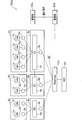
- FIG. 1 is an overall configuration diagram of a control system according to the first embodiment of the present invention.
- the control device 100a includes a plurality of first control units 3a, 3b, 3c, 3d, the same number of second control units 6a, 6b, 6c, 6d, a balancer 10a serving as a distribution circuit, and communication And the NIC 20 as a unit.
- the first control unit 3a is a CPU core as a physical CPU (Central Processing Unit), and by executing a program (program module), a plurality of virtual control units 1a and 1b that are VMs (Virtual Machines) The functions of the first buffers 2a and 2b, which are the queues, are realized.
- the virtual controllers 1a and 1b are virtual computers that operate on the hypervisor.
- the first buffers 2a and 2b are queues that output signals (packets) distributed from the second control unit 6a to the virtual control units 1a and 1b on a first-in first-out basis.
- the second control unit 6a is a CPU core as a physical CPU, and implements the functions of the Dispatcher 4a and the second buffer 5a that is a queue by executing a program. Note that one or both of the plurality of first control units 3a, 3b, 3c, and 3d and the same number of second control units 6a, 6b, 6c, and 6d are functional units of the CPU core. It can also be realized as a functional unit of a CPU device incorporating a plurality of CPU cores.
- the Dispatcher 4a has a function of distributing to the virtual control units 1a and 1b based on an identifier such as a destination IP address.
- the 1st control part 3b implement
- the second control unit 6b realizes functions of the Dispatcher 4b and the second buffer 5b.
- the 1st control part 3c implement
- the second control unit 6c realizes the functions of the Dispatcher 4c and the second buffer 5c.
- the first control unit 3d realizes the functions of the plurality of virtual control units 1g and 1h and the plurality of first buffers 2g and 2h.
- the second control unit 6d realizes the functions of the Dispatcher 4d and the second buffer 5d.
- the NIC 20 is a Network Interface Card, and is a communication unit connected to a network such as a LAN (Local Area Network) or a WAN (Wide Area Network).
- the Balancer 10a is a distribution circuit that includes a CPU_IF function unit 11, a Balancer function unit 12, a NIC_IF function unit 13, and general-purpose IFs 14a and 14b.
- the CPU_IF function unit 11 is hardware that has four output units and manages an interface with the second control units 6a, 6b, 6c, and 6d. Note that, as in a control device 100e (FIG. 5) which is a fifth embodiment described later, the CPU_IF function unit 11 may be configured by a CPU that realizes a function such as round robin.
- the NIC_IF function unit 13 is hardware that controls an interface with the NIC 20.
- the general-purpose IFs 14a and 14b are general-purpose queues.
- the general-purpose IF 14 a is a FIFO (First In First Out) memory (hardware) that relays between the CPU_IF function unit 11 and the balancer function unit 12.
- the general-purpose IF 14 b is a FIFO memory that relays between the balancer function unit 12 and the NIC_IF function unit 13.
- the Balancer function unit 12 is hardware that distributes a packet received by the NIC 20 into a plurality, and is a distribution unit configured by PLD (Programmable Logic Device), for example, FPGA (Field Programmable Gate Array).
- PLD Programmable Logic Device
- FPGA Field Programmable Gate Array
- the distributed packets are output to the four second buffers 5a, 5b, 5c, and 5d via the general-purpose IF 14a and the CPU_IF function unit 11.
- the balancer function unit 12 can realize an arbitrary distribution logic by using the PLD. That is, the balancer function unit 12 can be changed in function to any of different types of balancer function units (distribution units) such as the balancer function unit A12a, balancer function unit B12b, balancer function unit C12c, balancer function unit D12d, and the like. .
- the Balancer function unit 12 can change the function on a case-by-case basis by reconfiguring the Gate Array using FPGA.
- the balancer function unit 12 looks at a specific field of a packet, and if it can be processed with an equivalent flow, it is assigned to the same destination, or is assigned regardless of the nature of the packet, such as round robin. Or something. In addition, it can be said that what distributes to the same distribution destination has high directivity, and round robin with random distribution destination can have low directivity. Also, if the same flow is distributed to the same distribution destination, the randomness is low, and it can be distributed to a static virtual control unit (VM). Further, if the distribution is performed regardless of the nature of the packet, the randomness is high, and the distribution can be effectively performed when the number of virtual control units (VMs) and the arrangement location dynamically change.
- VMs virtual control units
- the balancer function unit 12 includes balancers having different functions such as a balancer function unit A12a, a balancer function unit B12b, a balancer function unit C12c, a balancer function unit D12d, and the like. You may comprise.
- control device 100a configures the balancer function unit 12 with FPGA hardware. Therefore, a plurality of balancer function units 12a are reconfigured on a case-by-case basis or set as options. , 12b, 12c, 12d.
- the Balancer 10a of the control device 100a of the first embodiment includes the Balancer function unit 12, and the number that can be distributed by the Balancer function unit 12 is equal to the number of the second control units 6a, 6b, 6c, and 6d. It was assumed. In the present embodiment, it is assumed that the number that can be distributed by the balancer function unit 12 is larger than the number of the second control units 6a, 6b, 6c, and 6d.
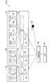
- FIG. 2 is a configuration diagram of a control apparatus according to the second embodiment of the present invention.
- the control device 100b includes a plurality of first control units 3a, 3b, 3c, and the same number of second control units 6a, 6b, 6c as the first control unit, A balancer 10a as a distribution circuit and a NIC 20 as a communication unit are provided.
- the 1st control part 3c implement achieves the function of several virtual control part 1e, 1f, 1g, 1h and several 1st buffer 2e, 2f, 2g, 2h. Since the number of virtual control units is larger than that of the first control units 3a and 3b, it is possible to perform parallel processing of light processing.
- the second control unit 6c realizes the functions of the Dispatcher 4c and the second buffer 5c.
- the Balancer 10a includes the Balancer function unit 12 (FIG. 1) in which the number that can be assigned is greater than the number of the second control units 6a, 6b, and 6c. That is, the balancer 10a includes a first output unit (distribution path) that is connected to the second control units 6a, 6b, and 6c on a one-to-one basis, and a second output unit (distribution path) that is not connected to the second control units 6a, 6b, and 6c. And have.
- the Balancer function unit 12 FIG. 1
- the balancer 10a includes a first output unit (distribution path) that is connected to the second control units 6a, 6b, and 6c on a one-to-one basis, and a second output unit (distribution path) that is not connected to the second control units 6a, 6b, and 6c. And have.
- control device 100b includes a management unit 30a that manages the second control units 6a, 6b, and 6c, a management unit 30b that manages the balancer 10a, and a notification IF that connects the management unit 30a and the management unit 30b so that they can communicate with each other. And is configured.
- Management units 30a and 30b specify the function of Balancer 10a.
- the management units 30a and 30b have a function of designating a second output unit of the balancer function unit 12 (FIG. 1) as a distribution unit.
- the balancer function unit 12 is connected to the second control units 6a, 6b, and 6c. Use the first output. That is, the management units 30a and 30b change the number of interfaces (output units) without changing the circuit of the Balancer 10a.
- the balancer function unit 12 includes balancers having different functions such as a balancer function unit A12a, a balancer function unit B12b, a balancer function unit C12c, a balancer function unit D12d, and the management units 30a and 30b switch between the function units. You may comprise.
- the balancer 10a can configure the maximum number of balancer function units 12 that can be assigned by the FPGA. And the 1st output part connected to the 2nd control parts 6a, 6b, and 6c is used, and the 2nd output part which is not connected to the 2nd control parts 6a, 6b, and 6c becomes unused.
- the management units 30a and 30b do not use a part of the distribution interface of the balancer function unit 10a. It can be configured not to be transmitted.
- FIG. 3 is a configuration diagram of a control apparatus according to the third embodiment of the present invention.
- the control device 100c includes a plurality of first control units 3a, 3b, and 3c, the same number of second control units 6a, 6b, and 6c as the first control unit, and a balancer function unit 12.
- a balancer 10a having (FIG. 1), a buffer 5e as a functional unit, and a NIC 20 as a communication unit are provided.
- the second control unit 6c realizes the functions of the Dispatcher 4c and the second buffer 5c.
- the buffer 5e may be realized by a new control unit, or may be realized by any of the first control units 3a, 3b, 3c and the second control units 6a, 6b, 6c.
- the balancer 10a has four output units, a second buffer 5a of the second control unit 6a, a second buffer 5b of the second control unit 6b, a second buffer 5c of the second control unit 6c, and a buffer 5e. It is connected.
- the buffer 5e stores a dummy “full” and is configured not to transmit a packet (information) from the balancer 10a.
- the balancer 10a has three packets for the second buffer 5a of the second controller 6a, the second buffer 5b of the second controller 6b, and the second buffer 5c of the second controller 6c. Sort out.
- the balancer 10a reduces the number of interfaces without changing its circuit.
- the control device 100c of the third embodiment uses one of the second buffer 5c and the buffer 5e, but may use the second buffer 5c and the buffer 5e.
- FIG. 4 is a configuration diagram of a control device according to the fourth embodiment of the present invention.
- the control device 100d includes a plurality of first control units 3a, 3b, and 3c, the same number of second control units 6a, 6b, and 6c as the first control unit, and a balancer function unit 12.
- a balancer 10a having (FIG. 1) and a NIC 20 as a communication unit are provided.
- the number that can be distributed by the Balancer function unit 12 is set to the maximum number of FPGA capabilities.
- the second control unit 6c realizes functions of the Dispatcher 4c and the plurality of second buffers 5c and 5d.
- the balancer 10a has four output units, a second buffer 5a of the second control unit 6a, a second buffer 5b of the second control unit 6b, and two second buffers 5c and 5d of the second control unit 6c, It is connected.
- the Dispatcher 4c merges the packets (signals) received from the two second buffers 5c and 5d, and distributes the merged signals to the first buffers 2e, 2f, 2g, and 2h of the first control unit 3c.
- the balancer function unit 12 (FIG. 1) of the balancer 10a can distribute packets without making a part of the distribution interface of the balancer function unit 10a unused.
- the control device 100b reduces the number of interfaces without changing the circuit of the balancer 10a. Further, the control device 100c of the third embodiment is configured to store a dummy “full” in the second buffer 5e so that information (packet) transmission is disabled. In the case of the control device 100c, the packet is transmitted to the second buffers 5a, 5b, 5c.
- FIG. 5 is a configuration diagram of a control device according to the fifth embodiment of the present invention.
- the control device 100e includes a plurality of first control units 3a, 3b, and 3c, the same number of second control units 6a, 6b, and 6c as the first control unit, and a balancer function unit 12.
- a balancer 10a having (FIG. 1), a buffer 5e as a functional unit, and a NIC 20 as a communication unit are provided.
- the number of balancer function units 12 that can be distributed is set to the maximum number of FPGA capabilities.
- the second control unit 6c realizes the functions of the Dispatcher 4c and the second buffer 5c.
- the balancer 10a has four output units, a second buffer 5a of the second control unit 6a, a second buffer 5b of the second control unit 6b, a second buffer 5c of the second control unit 6c, and a buffer 5e. It is connected. However, as in the third embodiment, the buffer 5e stores a dummy “full” and is configured not to transmit information (packets) from the balancer 10a.
- the balancer 10a includes a plurality of third buffers 15a, 15b, 15c, and 15d, a plurality of fourth buffers 15e, 15f, 15g, and 15h, and a distribution function unit 16.
- the plurality of third buffers 15a, 15b, 15c, and 15d and the plurality of fourth buffers 15e, 15f, 15g, and 15h correspond to the CPU_IF function 11 (FIG. 1) of the first embodiment. Since the fourth buffer 15h is connected to the buffer 5e in which the dummy “full” is stored, the packet cannot be transmitted to the second control unit 6c.
- the distribution function unit 16 distributes the packet received from the NIC 20 to the plurality of third buffers 15a, 15b, 15c, and 15d. That is, the distribution function unit 16 corresponds to the balancer function unit 12 (FIG. 1) of the first embodiment.
- the packets distributed to the third buffers 15a, 15b, 15c, and 15d are transmitted to the fourth buffers 15e, 15f, 15g, and 15h.
- packets distributed to the third buffers 15a, 15b, 15c, and 15d are distributed to the fourth buffers 15e, 15f, and 15g based on a distribution logic such as round robin.
- packets distributed to the third buffers 15a, 15b, and 15c are transmitted to the fourth buffers 15e, 15f, and 15g as a rule. Further, the packet distributed to the third buffer 15d should be distributed to the fourth buffer 15h, but is distributed to the other fourth buffers 15e, 15f, and 15g by round robin. The packets distributed to the fourth buffers 15e, 15f, and 15g are transmitted to the second buffers 5a, 5b, and 5c.
- the balancer 10a avoids a mismatch between the number of functions of the distribution function unit 16 and the number of outputs (the number of the fourth buffers 15e, 15f, 15g, and 15h).
- the management units 30a and 30b designate unused distribution interfaces. Specifically, the management units 30a and 30b designate the buffer 15h as unused. As a result, the packets distributed to the third buffer 15d are distributed to the fourth buffers 15e, 15f, and 15g by round robin.
- FIG. 6 is a configuration diagram of a control device which is a comparative example of the present invention.
- the control device 100f is used to compare with the control devices 100a to 100e of the embodiment.
- the control device 100f includes a plurality of first control units 3a, 3b, 3d, and 3e, the same number of second control units 6a, 6b, 6d, and 6e, a balancer 10b as a distribution circuit, and communication And the NIC 20 as a unit.
- the first control unit 3a is a CPU core as a physical CPU, and realizes functions of a plurality of virtual control units 1a and 1b and a plurality of first buffers 2a and 2b.
- the virtual controllers 1a and 1b are virtual computers that operate on the hypervisor.
- the first buffers 2a and 2b output signals (packets) distributed from the second control unit 6a to the virtual machines 1a and 1b in a first-in first-out manner.
- the second control unit 6a is a CPU core as a physical CPU, and implements the functions of the Dispatcher 4a and the second buffer 5a by executing a program.
- the 1st control part 3b implement
- the second control unit 6b realizes functions of the Dispatcher 4b and the second buffer 5b.
- the first control unit 3d realizes the functions of the plurality of virtual control units 1e and 1f and the plurality of first buffers 2e and 2f.
- the second control unit 6d realizes the functions of the Dispatcher 4d and the second buffer 5d.
- the first controller 3e realizes the functions of the plurality of virtual controllers 1g and 1h and the plurality of first buffers 2g and 2h.
- the second control unit 6e realizes the functions of the Dispatcher 4e and the second buffer 5e.
- the NIC 20 is a Network Interface Card and is a communication unit connected to a network.
- Balancer 10b is realized with dedicated hardware, not PLD, and only realizes a single distribution function.
- the balancer 10b distributes the packets received by the NIC 20 to the second controllers 6a, 6b, 6d, and 6e with a fixed single logic.
- the Balancer 10b is realized by dedicated hardware, so it is fast, while the number of distribution logic and distribution destinations is fixed.
- the balancer 10a of the control device 100a of the first embodiment is configured by a PLD, for example, an FPGA. Therefore, the Balancer function unit 12 can change the function to any one of the Balancer function unit A12a, the Balancer function unit B12b, the Balancer function unit C12c, the Balancer function unit D12d, and the like by reconfiguring the Gate Array.
- the balancer function unit 12 includes a balancer function unit A12a, a balancer function unit B12b, a balancer function unit C12c, a balancer function unit D12d, and the like, and each function unit can be switched by option setting.
- the number of distribution functions of the balancer 10a is different from the number of second control units 6a, 6b, and 6c that are distribution destinations.
- the present invention is not limited to the above-described embodiment, and various modifications such as the following are possible, for example.
- the first buffers 2a, 2b, 2c, 2d, 2e, 2f, 2g, and 2h and the second buffers 5a, 5b, 5c, 5d, and 5e according to each embodiment have a function of performing first-in first-out. However, it is also possible to write data at a predetermined address and take it out.
- the Dispatchers 4a, 4b, 4c, and 4d in each of the embodiments are connected to the plurality of virtual controllers (for example, the virtual controller of the first controller 3a) of the first controllers 3a, 3b, 3c, and 3d. It was distributed to the control units 1a and 1b).
- the Dispatcher 4a distributes all of the virtual controllers 1a, 1b, 1c, 1d, 1e, 1f, 1g, and 1h, and the other Dispatchers 4b, 4c, and 4d also include all the virtual controllers 1a, 1b, 1c, 1d, You may comprise so that it may distribute to any of 1e, 1f, 1g, and 1h.
- the Dispatchers 4a, 4b, 4c, and 4d of each of the embodiments are connected to the plurality of virtual controllers (for example, the virtual controller of the first controller 3a) of the first controllers 3a, 3b, 3c, and 3d. It was distributed to the control units 1a and 1b).
- Each Dispatcher 4a, 4b, 4c, 4d is not only a plurality of virtual control units of the first control units 3a, 3b, 3c, 3d connected to the Dispatcher 4a, 4b, 4c, 4d, but also other Dispatchers (for example, the Dispatcher 4a 4d) may be assigned.
Landscapes
- Engineering & Computer Science (AREA)
- Computer Networks & Wireless Communication (AREA)
- Signal Processing (AREA)
- Software Systems (AREA)
- Theoretical Computer Science (AREA)
- Physics & Mathematics (AREA)
- General Engineering & Computer Science (AREA)
- General Physics & Mathematics (AREA)
- Data Exchanges In Wide-Area Networks (AREA)
Abstract
【課題】振り分けロジックを柔軟に変更する。 【解決手段】ネットワークからパケットを受信する通信部(NIC20)と、複数の仮想制御部(VM1a,1b,1c・・・)として機能する複数の第1制御部3a,3b,3c,3dと、受信したパケットを複数に振り分ける振分回路(Balancer10a)と、振分回路が振り分けたパケットを複数の仮想制御部(VM1a,1b,1c・・・)に振り分ける複数の第2制御部(Dispatcher4a,4b,4c,4d)とを備え、振分回路は、PLDで構成されている。
Description
本発明は、制御装置、及び制御方法に関する。
ロードバランサ(Balancer)が処理要求(パケット)を複数に振り分け、振り分けられた処理要求を、複数のディスパッチャ(Dispatcher)が、該ディスパッチャと同数のサーバ(CPU)に振り分け、振り分けられたサーバが処理を実行する技術が開示されている(特許文献1参照)。また、特許文献1には、「ロードバランサBは、外部装置5から処理要求を取得すると、ラウンドロビン等によりその処理要求を複数のディスパッチャD(D1,D2,D3)のいずれかに振り分ける」と記載されている。
ここで、特許文献1に記載のロードバランサは、物理CPUを搭載し、ソフトウェアで実現しているのか、物理CPUを搭載することなく、ハードウェアロジックで実現しているのかまでは記載されていない。仮に、ロードバランサを専用ハードウェアで構成すれば、ソフトウェアで実現するよりも、高速になる一方、振り分けロジックや振り分け先の数が固定されてしまう。
本発明は、このような問題点を解決するためになされたものであり、振り分けロジックを柔軟に変更することができる制御装置、及び制御方法を提供することを目的とする。
請求項1に係る発明の制御装置は、ネットワークからパケットを受信する通信部(例えば、NIC)と、複数の仮想制御部(例えば、VM1a,1b,・・・)として機能する複数の第1制御部と、受信した前記パケットを複数に振り分ける振分回路(例えば、Balancer10a)と、前記振分回路が振り分けたパケットを前記複数の仮想制御部に振り分ける複数の第2制御部(例えば、Dispatcher4a,・・・)とを備え、前記振分回路は、PLD(Programmable Logic Device)で構成されていることを特徴とする。
これによれば、振分回路が受信したパケットを第2制御部に振り分ける。そして、第2制御部は、振り分けられたパケットを複数の仮想制御部に振り分ける。振分回路によって、第2制御部を複数備えられるので、複数の仮想制御部を構成する第1制御部の数を増加させることができる。
ここで、PLDで構成された振分回路が複数の第2制御部にパケットを振り分けるので、専用ハードウェアで構成するよりも、柔軟性が高く、ケースバイケースで振り分けロジックを変更することができる。また、ソフトウェアでパケットを振り分けるよりも、高速化を実現することができる。なお、第1制御部及び第2制御部の何れか一方又は双方は、CPUコアやCPUデバイスの機能部として構成することができる。
ここで、PLDで構成された振分回路が複数の第2制御部にパケットを振り分けるので、専用ハードウェアで構成するよりも、柔軟性が高く、ケースバイケースで振り分けロジックを変更することができる。また、ソフトウェアでパケットを振り分けるよりも、高速化を実現することができる。なお、第1制御部及び第2制御部の何れか一方又は双方は、CPUコアやCPUデバイスの機能部として構成することができる。
請求項2に係る発明は、請求項1に記載の制御装置であって、前記振分回路は、切替え可能な複数種類の振分部を備え、前記複数種類の振分部は、設定又は管理部の制御により、切り替えられることを特徴とする。
これによれば、複数種類の振分部は、その何れかにケースバイケースで切り替えられる。つまり、振り分けロジックを柔軟に変更することができる。
請求項3に係る発明は、請求項1に記載の制御装置であって、前記振分回路は、前記第2制御部と1対1接続されている複数の第1出力部と、前記第2制御部と接続されていない第2出力部とを有し、前記第1出力部と前記第2出力部との何れを振り分け経路とするかを管理する管理部をさらに備えることを特徴とする。
これによれば、振分回路は、第2制御部(例えば、Dispatcher)の数よりも多い数の出力部(例えば、CPU_IF機能部11の出力部)を備えておくことができる。つまり、振分回路は、ハードウェア上の限界まで、最大数の出力部(第1出力部又は第2出力部)を構成することができる。
請求項4に係る発明は、請求項1に記載の制御装置であって、前記振分回路は、前記第2制御部と1対1接続されている複数の第1出力部と、前記第2制御部と接続されていない第2出力部とを有し、前記第2出力部の出力信号経路が遮断されることを特徴とする。
これによれば、振分回路は、ハードウェア上の限界まで、最大数の出力部(第1出力部又は第2出力部)を構成することができる。
請求項5に係る発明は、請求項3又は請求項4に記載の制御装置であって、前記振分回路は、前記第2出力部に送信されるべきパケットを、ラウンドロビンを用いて第1出力部に振り分け直すことを特徴とする。
これによれば、複数の第1出力部は、1対1接続されている第2制御部を負荷分散する。また、第2出力部は、負荷を有さない。
請求項6に係る発明は、請求項1に記載の制御装置であって、前記振分回路は、前記第2制御部と1対1接続されている複数の第1出力部と、他の前記第2制御部と接続されている複数の第2出力部とを有し、他の何れかの前記第2制御部は、複数の前記第2出力部からの信号をマージすることを特徴とする。
これによれば、第1出力部の数と第2出力部の数との和が第2制御部の数よりも多くても、全ての出力部(第1出力部及び第2出力部)を使用することができる。
請求項7に係る発明は、請求項1に記載の制御装置であって、何れかの前記第2制御部(例えば、Dispatcher)は、自身に接続される前記仮想制御部にパケットを振り分けると共に、他の第2制御部に接続されている他の前記仮想制御部にパケットを振り分けることを特徴とする。
これによれば、何れかの第2制御部は、他の第2制御部を介して、他の前記仮想制御部にパケットを振り分けたり、他の第2制御部を介することなく、他の仮想制御部にパケットを振り分けたりする。
請求項8に係る発明は、ネットワークからパケットを受信する通信部と、受信した前記パケットを複数に振り分け、PLDで構成された振分回路と、前記振分回路が振り分けたパケットを処理する複数の制御部を備える制御装置が実行される制御方法であって、前記PLDが異なる種類の振分部に再構成させられるステップを有することを特徴とする。
これによれば、PLDは、複数種類の振分部(例えば、Balancer機能部A12a、Balancer機能部B12b、Balancer機能部C12c、Balancer機能部D12d)の何れかに再構成させられる。つまり、振分回路は、ケースバイケースで振り分けロジックを変更することができる。
なお、振分回路は、パケットの特定のフィールドの内容に基づいて、何れかの第1出力部に切り替え、各々の第2制御部は、識別子を用いて、各々の仮想制御部に振り分ける振分機能を実現することができる。
本発明によれば、振り分けロジックを柔軟に変更することが可能な制御装置を構成することができる。
以下、図面を参照して、本発明の実施の形態(以下、「本実施形態」と称する)につき詳細に説明する。なお、各図は、本発明を十分に理解できる程度に、概略的に示してあるに過ぎない。また、各図において、共通する構成要素や同様な構成要素については、同一の符号を付し、それらの重複する説明を省略する。
(第1実施形態)
図1は、本発明の第1実施形態である制御システムの全体構成図である。
制御装置100aは、複数の第1制御部3a,3b,3c,3dと、該第1制御部と同数の第2制御部6a,6b,6c,6dと、振分回路としてのBalancer10aと、通信部としてのNIC20とを備えて構成される。
図1は、本発明の第1実施形態である制御システムの全体構成図である。
制御装置100aは、複数の第1制御部3a,3b,3c,3dと、該第1制御部と同数の第2制御部6a,6b,6c,6dと、振分回路としてのBalancer10aと、通信部としてのNIC20とを備えて構成される。
第1制御部3aは、物理CPU(Central Processing Unit)としてのCPUコアであり、プログラム(プログラムモジュール)を実行することにより、複数のVM(Virtual Machine)である仮想制御部1a,1bと、複数のキューである第1バッファ2a,2bとの機能を実現する。仮想制御部1a,1bは、ハイパバイザ上で動作する仮想的なコンピュータである。第1バッファ2a,2bは、第2制御部6aから振り分けられた信号(パケット)を先入れ先出しで仮想制御部1a,1bに出力するキューである。
第2制御部6aは、物理CPUとしてのCPUコアであり、プログラムを実行することにより、Dispatcher4aと、キューである第2バッファ5aとの機能を実現する。なお、複数の第1制御部3a,3b,3c,3dと、該第1制御部と同数の第2制御部6a,6b,6c,6dとの何れか一方又は双方は、CPUコアの機能部としても実現可能であり、また、複数のCPUコアを内蔵するCPUデバイスの機能部としても実現可能である。
Dispatcher4aは、例えば、宛先IPアドレス等の識別子に基づいて、仮想制御部1a,1bに振り分ける機能を有する。同様に、第1制御部3bは、複数の仮想制御部1c,1dと、複数の第1バッファ2c,2dとの機能を実現する。第2制御部6bは、Dispatcher4bと、第2バッファ5bとの機能を実現する。また、第1制御部3cは、複数の仮想制御部1e,1fと、複数の第1バッファ2e,2fとの機能を実現する。第2制御部6cは、Dispatcher4cと、第2バッファ5cとの機能を実現する。また、第1制御部3dは、複数の仮想制御部1g,1hと、複数の第1バッファ2g,2hとの機能を実現する。第2制御部6dは、Dispatcher4dと、第2バッファ5dとの機能を実現する。NIC20は、Network Interface Cardであり、LAN(Local Area Network)やWAN(Wide Area Network)等のネットワークに接続される通信部である。
Balancer10aは、CPU_IF機能部11と、Balancer機能部12と、NIC_IF機能部13と、汎用IF14a,14bとを備えて構成される振分回路である。CPU_IF機能部11は、4つの出力部を有し、第2制御部6a,6b,6c,6dとのインタフェースを司るハードウェアである。なお、後記する第5実施形態である制御装置100e(図5)のように、CPU_IF機能部11は、ラウンドロビン等の機能を実現するCPUで構成されることもある。
NIC_IF機能部13は、NIC20とのインタフェースを司るハードウェアである。汎用IF14a,14bは、汎用のキューである。特に、汎用IF14aは、CPU_IF機能部11とBalancer機能部12との間を中継するFIFO(First In First Out)メモリ(ハードウェア)である。汎用IF14bは、Balancer機能部12とNIC_IF機能部13との間を中継するFIFOメモリである。
Balancer機能部12は、NIC20が受信したパケットを複数に振り分けるハードウェアであり、PLD(Programmable Logic Device)、例えば、FPGA(Field Programmable Gate Array)で構成される振分部である。そして、振り分けられたパケットは、汎用IF14a、及びCPU_IF機能部11を介して、4つの第2バッファ5a,5b,5c,5dに出力される。Balancer機能部12は、PLDを用いることにより、任意の振り分けロジックを実現することができる。つまり、Balancer機能部12は、Balancer機能部A12a、Balancer機能部B12b、Balancer機能部C12c、Balancer機能部D12d等の異なる種類のBalancer機能部(振分部)の何れかに機能変更することができる。また、Balancer機能部12は、FPGAを用い、Gate Arrayを再構成することにより、ケースバイケースで機能変更することができる。
例えば、Balancer機能部12は、パケットの特定のフィールドを見て、同等のフローで処理可能であれば、同じ振り分け先に振り分けるものであったり、ラウンドロビンのように、パケットの性質に無関係に振り分けるものであったりする。なお、同じ振り分け先に振り分けるものは、指向性が高いということができ、振り分け先がランダムなラウンドロビンは、指向性が低いということができる。また、同等のフローを示したものを同じ振り分け先に振り分ければ、ランダム性が低く、静的な仮想制御部(VM)に振り分けることができる。また、パケットの性質によらずに振り分ければ、ランダム性が高く、仮想制御部(VM)の数や配置場所が動的に変動する場合に有効に振り分けることができる。
また、Balancer機能部12は、Balancer機能部A12a、Balancer機能部B12b、Balancer機能部C12c、Balancer機能部D12d等の異なる機能のBalancerを有し、オプション設定により、各機能部を切り替えることができるように構成しても構わない。
以上説明したように、本実施形態の制御装置100aは、Balancer機能部12をFPGAのハードウェアで構成するので、ケースバイケースで再構成したり、オプション設定することにより、複数のBalancer機能部12a,12b,12c,12dの何れかに切り替えることができる。
(第2実施形態)
前記第1実施形態の制御装置100aのBalancer10aは、Balancer機能部12を備え、Balancer機能部12が振り分けることができる数と、第2制御部6a,6b,6c,6dの数とが等しいことを前提としていた。本実施形態では、Balancer機能部12が振り分け可能な数の方が第2制御部6a,6b,6c,6dの数よりも多いことを前提とする。
前記第1実施形態の制御装置100aのBalancer10aは、Balancer機能部12を備え、Balancer機能部12が振り分けることができる数と、第2制御部6a,6b,6c,6dの数とが等しいことを前提としていた。本実施形態では、Balancer機能部12が振り分け可能な数の方が第2制御部6a,6b,6c,6dの数よりも多いことを前提とする。
図2は、本発明の第2実施形態である制御装置の構成図である。
制御装置100bは、前記第1実施形態の制御装置100aと同様に、複数の第1制御部3a,3b,3cと、該第1制御部と同数の第2制御部6a,6b,6cと、振分回路としてのBalancer10aと、通信部としてのNIC20とを備える。ここで、第1制御部3cは、複数の仮想制御部1e,1f,1g,1hと、複数の第1バッファ2e,2f,2g,2hとの機能を実現する。第1制御部3a,3bよりも仮想制御部の数が多いので、処理が軽い制御を並列処理することができる。第2制御部6cは、Dispatcher4cと、第2バッファ5cとの機能を実現する。
制御装置100bは、前記第1実施形態の制御装置100aと同様に、複数の第1制御部3a,3b,3cと、該第1制御部と同数の第2制御部6a,6b,6cと、振分回路としてのBalancer10aと、通信部としてのNIC20とを備える。ここで、第1制御部3cは、複数の仮想制御部1e,1f,1g,1hと、複数の第1バッファ2e,2f,2g,2hとの機能を実現する。第1制御部3a,3bよりも仮想制御部の数が多いので、処理が軽い制御を並列処理することができる。第2制御部6cは、Dispatcher4cと、第2バッファ5cとの機能を実現する。
ここで、Balancer10aは、振り分け可能な数が第2制御部6a,6b,6cの数よりも多いBalancer機能部12(図1)を備えているものとする。つまり、Balancer10aは、第2制御部6a,6b,6cと1対1接続する第1出力部(振り分け経路)と、第2制御部6a,6b,6cに接続されない第2出力部(振り分け経路)とを有している。さらに、制御装置100bは、第2制御部6a,6b,6cを管理する管理部30aと、Balancer10aを管理する管理部30bと、管理部30aと管理部30bとを通信可能に接続する通知用IFとを備えて構成される。
管理部30a,30bは、Balancer10aの機能を指定する。具体的には、管理部30a,30bは、振分部としてのBalancer機能部12(図1)の第2出力部を指定する機能を有する。ここでは、管理部30a,30bは、第2制御部6a,6b,6cの数が3つであるので、Balancer機能部12は、第2制御部6a,6b,6cに接続されている3つの第1出力部を使用する。つまり、管理部30a,30bは、Balancer10aの回路を変更することなく、インタフェース(出力部)の数を変更する。また、Balancer機能部12は、Balancer機能部A12a、Balancer機能部B12b、Balancer機能部C12c、Balancer機能部D12d等の異なる機能のBalancerを有し、管理部30a,30bが各機能部を切り替えるように構成しても構わない。
制御装置100bによれば、Balancer10aは、最大限の振り分け可能数のBalancer機能部12を、FPGAで構成することができる。そして、第2制御部6a,6b,6cに接続されている第1出力部を使用し、第2制御部6a,6b,6cに接続されていない第2出力部が未使用になる。
(第3実施形態)
前記第2実施形態では、管理部30a,30bがBalancer機能部10aの振り分けインタフェースの一部を未使用にしたが、Balancer10aに接続される第2制御部6a,6b,6cの何れかまでパケットが送信されないように構成することができる。
前記第2実施形態では、管理部30a,30bがBalancer機能部10aの振り分けインタフェースの一部を未使用にしたが、Balancer10aに接続される第2制御部6a,6b,6cの何れかまでパケットが送信されないように構成することができる。
図3は、本発明の第3実施形態である制御装置の構成図である。
制御装置100cは、前記第2実施形態と同様に、複数の第1制御部3a,3b,3cと、該第1制御部と同数の第2制御部6a,6b,6cと、Balancer機能部12(図1)を有するBalancer10aと、機能部としてのバッファ5eと、通信部としてのNIC20とを備える。ここで、Balancer機能部12の振り分け可能な数は、FPGAの能力の最大数に設定されているものとする。第2制御部6cは、Dispatcher4cと、第2バッファ5cとの機能を実現する。なお、バッファ5eは、新たな制御部が実現しても、第1制御部3a,3b,3c及び第2制御部6a,6b,6c何れが実現しても構わない。
制御装置100cは、前記第2実施形態と同様に、複数の第1制御部3a,3b,3cと、該第1制御部と同数の第2制御部6a,6b,6cと、Balancer機能部12(図1)を有するBalancer10aと、機能部としてのバッファ5eと、通信部としてのNIC20とを備える。ここで、Balancer機能部12の振り分け可能な数は、FPGAの能力の最大数に設定されているものとする。第2制御部6cは、Dispatcher4cと、第2バッファ5cとの機能を実現する。なお、バッファ5eは、新たな制御部が実現しても、第1制御部3a,3b,3c及び第2制御部6a,6b,6c何れが実現しても構わない。
Balancer10aは、4つの出力部を有し、第2制御部6aの第2バッファ5aと、第2制御部6bの第2バッファ5bと、第2制御部6cの第2バッファ5cと、バッファ5eと接続されている。また、バッファ5eは、ダミー「full」が格納されており、Balancer10aからパケット(情報)が伝送されないように構成されている。
この構成により、Balancer10aは、第2制御部6aの第2バッファ5aと、第2制御部6bの第2バッファ5bと、第2制御部6cの第2バッファ5cとに対して、パケットを3つに振り分ける。Balancer10aは、その回路を変更することなく、インタフェースの数が減少する。
(第4実施形態)
前記第3実施形態の制御装置100cは、第2バッファ5c及びバッファ5eの一方の第2バッファ5cを使用したが、第2バッファ5c及びバッファ5eを使用することもできる。
前記第3実施形態の制御装置100cは、第2バッファ5c及びバッファ5eの一方の第2バッファ5cを使用したが、第2バッファ5c及びバッファ5eを使用することもできる。
図4は、本発明の第4実施形態である制御装置の構成図である。
制御装置100dは、前記第3実施形態と同様に、複数の第1制御部3a,3b,3cと、該第1制御部と同数の第2制御部6a,6b,6cと、Balancer機能部12(図1)を有するBalancer10aと、通信部としてのNIC20とを備える。ここで、Balancer機能部12の振り分け可能な数は、FPGAの能力の最大数に設定されている。第2制御部6cは、Dispatcher4cと、複数の第2バッファ5c,5dとの機能を実現する。
制御装置100dは、前記第3実施形態と同様に、複数の第1制御部3a,3b,3cと、該第1制御部と同数の第2制御部6a,6b,6cと、Balancer機能部12(図1)を有するBalancer10aと、通信部としてのNIC20とを備える。ここで、Balancer機能部12の振り分け可能な数は、FPGAの能力の最大数に設定されている。第2制御部6cは、Dispatcher4cと、複数の第2バッファ5c,5dとの機能を実現する。
Balancer10aは、4つの出力部を有し、第2制御部6aの第2バッファ5aと、第2制御部6bの第2バッファ5bと、第2制御部6cの2つの第2バッファ5c,5dと接続されている。Dispatcher4cは、2つの第2バッファ5c,5dから受け取るパケット(信号)をマージ(併合)し、マージされた信号を第1制御部3cの第1バッファ2e,2f,2g,2hに振り分ける。
このため、Balancer10aのBalancer機能部12(図1)は、Balancer機能部10aの振り分けインタフェースの一部を未使用にすることなく、パケットを振り分けることができる。
(第5実施形態)
前記第2実施形態の制御装置100bは、Balancer10aの回路を変更することなく、インタフェースの数を減少させた。また、前記第3実施形態の制御装置100cは、第2バッファ5eにダミー「full」を格納し、情報(パケット)伝送不可になるように構成していた。制御装置100cの場合において、パケットは、第2バッファ5a,5b,5cに送信される。
前記第2実施形態の制御装置100bは、Balancer10aの回路を変更することなく、インタフェースの数を減少させた。また、前記第3実施形態の制御装置100cは、第2バッファ5eにダミー「full」を格納し、情報(パケット)伝送不可になるように構成していた。制御装置100cの場合において、パケットは、第2バッファ5a,5b,5cに送信される。
図5は、本発明の第5実施形態である制御装置の構成図である。
制御装置100eは、前記第3実施形態と同様に、複数の第1制御部3a,3b,3cと、該第1制御部と同数の第2制御部6a,6b,6cと、Balancer機能部12(図1)を有するBalancer10aと、機能部としてのバッファ5eと、通信部としてのNIC20とを備える。Balancer機能部12の振り分け可能な数は、FPGAの能力の最大数に設定されている。第2制御部6cは、Dispatcher4cと、第2バッファ5cとの機能を実現する。
制御装置100eは、前記第3実施形態と同様に、複数の第1制御部3a,3b,3cと、該第1制御部と同数の第2制御部6a,6b,6cと、Balancer機能部12(図1)を有するBalancer10aと、機能部としてのバッファ5eと、通信部としてのNIC20とを備える。Balancer機能部12の振り分け可能な数は、FPGAの能力の最大数に設定されている。第2制御部6cは、Dispatcher4cと、第2バッファ5cとの機能を実現する。
Balancer10aは、4つの出力部を有し、第2制御部6aの第2バッファ5aと、第2制御部6bの第2バッファ5bと、第2制御部6cの第2バッファ5cと、バッファ5eと接続されている。但し、バッファ5eは、前記第3実施形態のように、ダミー「full」が格納されており、Balancer10aから情報(パケット)が伝送されないように構成されている。
Balancer10aは、複数の第3バッファ15a,15b,15c,15dと、複数の第4バッファ15e,15f,15g,15hと、振分機能部16とを備えて構成される。ここで、複数の第3バッファ15a,15b,15c,15d、及び複数の第4バッファ15e,15f,15g,15hは、前記第1実施形態のCPU_IF機能11(図1)に相当する。第4バッファ15hは、ダミー「full」が格納されているバッファ5eに接続されているので、パケットを第2制御部6cに送信することができない。
振分機能部16は、NIC20から受信したパケットを複数の第3バッファ15a,15b,15c,15dに振り分ける。つまり、振分機能部16は、前記第1実施形態のBalancer機能部12(図1)に相当する。第3バッファ15a,15b,15c,15dに振り分けられたパケットは、原則的に、第4バッファ15e,15f,15g,15hに送信される。しかしながら、第3バッファ15hは使用不可なので、第3バッファ15a,15b,15c,15dに振り分けられたパケットは、ラウンドロビン等の振り分けロジックに基づいて、第4バッファ15e,15f,15gに振り分けられる。
例えば、第3バッファ15a,15b,15cに振り分けられたパケットは、原則通り、第4バッファ15e,15f,15gに送信される。さらに、また、第3バッファ15dに振り分けられたパケットは、第4バッファ15hに振り分けられるべきであるが、他の第4バッファ15e,15f,15gにラウンドロビンで振り分けられる。そして、第4バッファ15e,15f,15gに振り分けられたパケットは、第2バッファ5a,5b,5cに送信される。
つまり、Balancer10aは、振分機能部16の機能数と、出力数(第4バッファ15e,15f,15g,15hの数)との不一致を回避する。
また、前記第2実施形態では、管理部30a,30b(図2)が未使用な振り分けインタフェースを指定していた。具体的に、管理部30a,30bは、バッファ15hを未使用に指定する。これにより、第3バッファ15dに振り分けられたパケットは、第4バッファ15e,15f,15gにラウンドロビンで振り分けられる。
(比較例)
図6は、本発明の比較例である制御装置の構成図である。
以下、制御装置100fを用いて、前記実施形態の制御装置100a~100eと比較する。制御装置100fは、複数の第1制御部3a,3b,3d,3eと、該第1制御部と同数の第2制御部6a,6b,6d,6eと、振分回路としてのBalancer10bと、通信部としてのNIC20とを備えて構成される。
図6は、本発明の比較例である制御装置の構成図である。
以下、制御装置100fを用いて、前記実施形態の制御装置100a~100eと比較する。制御装置100fは、複数の第1制御部3a,3b,3d,3eと、該第1制御部と同数の第2制御部6a,6b,6d,6eと、振分回路としてのBalancer10bと、通信部としてのNIC20とを備えて構成される。
第1制御部3aは、物理CPUとしてのCPUコアであり、複数の仮想制御部1a,1bと、複数の第1バッファ2a,2bとの機能を実現する。仮想制御部1a,1bは、ハイパバイザ上で動作する仮想的なコンピュータである。第1バッファ2a,2bは、第2制御部6aから振り分けられた信号(パケット)を先入れ先出しで仮想マシン1a,1bに出力する。
第2制御部6aは、物理CPUとしてのCPUコアであり、プログラムを実行することにより、Dispatcher4aと、第2バッファ5aとの機能を実現する。同様に、第1制御部3bは、複数の仮想制御部1c,1dと、複数の第1バッファ2c,2dとの機能を実現する。第2制御部6bは、Dispatcher4bと、第2バッファ5bとの機能を実現する。また、第1制御部3dは、複数の仮想制御部1e,1fと、複数の第1バッファ2e,2fとの機能を実現する。第2制御部6dは、Dispatcher4dと、第2バッファ5dとの機能を実現する。また、第1制御部3eは、複数の仮想制御部1g,1hと、複数の第1バッファ2g,2hとの機能を実現する。第2制御部6eは、Dispatcher4eと、第2バッファ5eとの機能を実現する。NIC20は、Network Interface Cardであり、ネットワークに接続される通信部である。
Balancer10bは、PLDでなく、専用ハードウェアで実現されており、単一の振分機能のみを実現する。Balancer10bは、NIC20が受信したパケットを固定された単一ロジックで第2制御部6a,6b,6d,6eに振り分ける。
Balancer10bは、専用ハードウェアで実現されているので、高速である一方、振り分けロジックや振り分け先の数が固定されている。しかしながら、前記第1実施形態の制御装置100aのBalancer10aはPLD、例えばFPGAで構成されている。このため、Balancer機能部12は、Gate Arrayを再構成することにより、Balancer機能部A12a、Balancer機能部B12b、Balancer機能部C12c、Balancer機能部D12d等の何れかに機能変更することができる。また、Balancer機能部12は、Balancer機能部A12a、Balancer機能部B12b、Balancer機能部C12c、Balancer機能部D12d等を有し、オプション設定により、各機能部を切り替えることができる。
また、前記第2,3,4実施形態の制御装置100b,100c,100dは、Balancer10aの振り分け機能の数と、振り分け先である第2制御部6a,6b,6cの数とが異なっている。
(変形例)
本発明は前記した実施形態に限定されるものではなく、例えば、以下のような種々の変形が可能である。
(1)前記各実施形態の第1バッファ2a,2b,2c,2d,2e,2f,2g,2hや、第2バッファ5a,5b,5c,5d,5eは、先入れ先だしを行う機能を有していたが、所定のアドレスにデータを書き込み、それを取り出すものであっても構わない。
本発明は前記した実施形態に限定されるものではなく、例えば、以下のような種々の変形が可能である。
(1)前記各実施形態の第1バッファ2a,2b,2c,2d,2e,2f,2g,2hや、第2バッファ5a,5b,5c,5d,5eは、先入れ先だしを行う機能を有していたが、所定のアドレスにデータを書き込み、それを取り出すものであっても構わない。
(2)前記各実施形態のDispatcher4a,4b,4c,4dは、それぞれに接続している第1制御部3a,3b,3c,3dの複数の仮想制御部(例えば、第1制御部3aの仮想制御部1a,1b)に振り分けていた。Dispatcher4aは、全ての仮想制御部1a,1b,1c,1d,1e,1f,1g,1hの何れかに振り分け、他のDispatcher4b,4c,4dも全ての仮想制御部1a,1b,1c,1d,1e,1f,1g,1hの何れかに振り分けるように構成しても構わない。
(3)前記各実施形態のDispatcher4a,4b,4c,4dは、それぞれに接続している第1制御部3a,3b,3c,3dの複数の仮想制御部(例えば、第1制御部3aの仮想制御部1a,1b)に振り分けていた。各々のDispatcher4a,4b,4c,4dは、それぞれに接続している第1制御部3a,3b,3c,3dの複数の仮想制御部だけでなく、他のDispatcher(例えば、Dispatcher4aがDispatcher4b,4c,4d)に振り分けることもある。
1,1a,1b,1c,1d,1e,1f,1g,1h 仮想制御部
2,2a,2b,2c,2d,2e,2f,2g,2h 第1バッファ(キュー)
3,3a,3b,3c 第1制御部
4,4a,4b,4c,4d Dispatcher
5,5a,5b,5c,5d 第2バッファ(キュー)
5e バッファ(full)
6,6a,6b,6c,6d 第2制御部
7a,7b,7c, 第3制御部
10a Balancer(振分回路、PLD,FPGA)
10b Balancer(専用ハードウェア)
11 CPU_IF機能部(第1出力部,第2出力部)
12 Balancer機能部
12a,12b,12c,12d Balancer機能部(振分部)
13 NIC_IF機能部
14a,14b 汎用IF(キュー)
15a,15b,15c,15d 第3バッファ
15e,15f,15g,15h 第4バッファ
16 振分機能部
20 NIC(通信部)
30a,30b 管理部
100a,100b,100c,100d,100e,100f,100g 制御装置
2,2a,2b,2c,2d,2e,2f,2g,2h 第1バッファ(キュー)
3,3a,3b,3c 第1制御部
4,4a,4b,4c,4d Dispatcher
5,5a,5b,5c,5d 第2バッファ(キュー)
5e バッファ(full)
6,6a,6b,6c,6d 第2制御部
7a,7b,7c, 第3制御部
10a Balancer(振分回路、PLD,FPGA)
10b Balancer(専用ハードウェア)
11 CPU_IF機能部(第1出力部,第2出力部)
12 Balancer機能部
12a,12b,12c,12d Balancer機能部(振分部)
13 NIC_IF機能部
14a,14b 汎用IF(キュー)
15a,15b,15c,15d 第3バッファ
15e,15f,15g,15h 第4バッファ
16 振分機能部
20 NIC(通信部)
30a,30b 管理部
100a,100b,100c,100d,100e,100f,100g 制御装置
Claims (8)
- ネットワークからパケットを受信する通信部と、
複数の仮想制御部として機能する複数の第1制御部と、
受信した前記パケットを複数に振り分ける振分回路と、
前記振分回路が振り分けたパケットを前記複数の仮想制御部に振り分ける複数の第2制御部とを備え、
前記振分回路は、PLDで構成されている
ことを特徴とする制御装置。 - 請求項1に記載の制御装置であって、
前記振分回路は、切替え可能な複数種類の振分部を備え、
前記複数種類の振分部は、設定又は管理部の制御により、切り替えられる
ことを特徴とする制御装置。 - 請求項1に記載の制御装置であって、
前記振分回路は、前記第2制御部と1対1接続されている複数の第1出力部と、前記第2制御部と接続されていない第2出力部とを有し、
前記第1出力部と前記第2出力部との何れを振り分け経路とするかを管理する管理部をさらに備える
ことを特徴とする制御装置。 - 請求項1に記載の制御装置であって、
前記振分回路は、前記第2制御部と1対1接続されている複数の第1出力部と、前記第2制御部と接続されていない第2出力部とを有し、
前記第2出力部の出力信号経路が遮断される
ことを特徴とする制御装置。 - 請求項3又は請求項4に記載の制御装置であって、
前記振分回路は、前記第2出力部に送信されるべきパケットを、ラウンドロビンを用いて第1出力部に振り分け直す
ことを特徴とする制御装置。 - 請求項1に記載の制御装置であって、
前記振分回路は、何れか複数の前記第2制御部と1対1接続されている複数の第1出力部と、他の前記第2制御部と接続されている複数の第2出力部とを有し、
他の何れかの前記第2制御部は、複数の前記第2出力部からの信号をマージする
ことを特徴とする制御装置。 - 請求項1に記載の制御装置であって、
何れかの前記第2制御部は、自身に接続される前記仮想制御部にパケットを振り分けると共に、他の第2制御部に接続されている他の前記仮想制御部にパケットを振り分ける
ことを特徴とする制御装置。 - ネットワークからパケットを受信する通信部と、
受信した前記パケットを複数に振り分け、PLDで構成された振分回路と、
前記振分回路が振り分けたパケットを処理する複数の制御部を備える制御装置が実行される制御方法であって、
前記PLDが異なる種類の振分部に再構成させられるステップを有することを特徴とする制御方法。
Priority Applications (1)
| Application Number | Priority Date | Filing Date | Title |
|---|---|---|---|
| US16/977,139 US11509573B2 (en) | 2018-03-02 | 2019-02-21 | Control device and control method |
Applications Claiming Priority (2)
| Application Number | Priority Date | Filing Date | Title |
|---|---|---|---|
| JP2018037025A JP6977621B2 (ja) | 2018-03-02 | 2018-03-02 | 制御装置、及び制御方法 |
| JP2018-037025 | 2018-03-02 |
Publications (1)
| Publication Number | Publication Date |
|---|---|
| WO2019167802A1 true WO2019167802A1 (ja) | 2019-09-06 |
Family
ID=67806276
Family Applications (1)
| Application Number | Title | Priority Date | Filing Date |
|---|---|---|---|
| PCT/JP2019/006614 Ceased WO2019167802A1 (ja) | 2018-03-02 | 2019-02-21 | 制御装置、及び制御方法 |
Country Status (3)
| Country | Link |
|---|---|
| US (1) | US11509573B2 (ja) |
| JP (1) | JP6977621B2 (ja) |
| WO (1) | WO2019167802A1 (ja) |
Families Citing this family (3)
| Publication number | Priority date | Publication date | Assignee | Title |
|---|---|---|---|---|
| JP7087807B2 (ja) * | 2018-08-08 | 2022-06-21 | 日本電信電話株式会社 | サーバ、サーバシステム及びサーバのネットワーク帯域増加方法 |
| US20220321403A1 (en) * | 2021-04-02 | 2022-10-06 | Nokia Solutions And Networks Oy | Programmable network segmentation for multi-tenant fpgas in cloud infrastructures |
| WO2023243098A1 (ja) | 2022-06-17 | 2023-12-21 | 日本電信電話株式会社 | アクセラレータオフロード装置、アクセラレータオフロード方法およびプログラム |
Citations (6)
| Publication number | Priority date | Publication date | Assignee | Title |
|---|---|---|---|---|
| JP2011160041A (ja) * | 2010-01-29 | 2011-08-18 | Nec Corp | フロントエンドシステム、フロントエンド処理方法 |
| JP2013105308A (ja) * | 2011-11-14 | 2013-05-30 | Nippon Telegr & Teleph Corp <Ntt> | 負荷分散システム、負荷分散装置、負荷分散方法および負荷分散プログラム |
| JP2014032530A (ja) * | 2012-08-03 | 2014-02-20 | Nippon Telegr & Teleph Corp <Ntt> | 分散処理システムおよび分散処理方法 |
| JP2014106728A (ja) * | 2012-11-27 | 2014-06-09 | Canon Marketing Japan Inc | マルチテナント型サービスシステム、情報処理装置、制御方法、及びプログラム |
| JP2017139597A (ja) * | 2016-02-03 | 2017-08-10 | 日本電信電話株式会社 | ネットワーク負荷分散装置および方法 |
| JP2017220846A (ja) * | 2016-06-09 | 2017-12-14 | 日本電信電話株式会社 | 保守減設システム、ノードおよび保守減設方法 |
Family Cites Families (16)
| Publication number | Priority date | Publication date | Assignee | Title |
|---|---|---|---|---|
| US7333570B2 (en) * | 2000-03-14 | 2008-02-19 | Altera Corporation | Clock data recovery circuitry associated with programmable logic device circuitry |
| KR100567326B1 (ko) * | 2003-12-24 | 2006-04-04 | 한국전자통신연구원 | Sonet/sdh, pdh, 그리고 이더넷 신호의 통합스위칭/전달 장치 및 그 방법 |
| US7783839B2 (en) * | 2007-01-08 | 2010-08-24 | International Business Machines Corporation | Using different algorithms to destage different types of data from cache |
| KR101399553B1 (ko) * | 2007-03-09 | 2014-05-27 | 삼성전자주식회사 | 멀티미디어 스트림 전송 장치 및 방법 |
| US9600332B2 (en) * | 2009-04-28 | 2017-03-21 | Cisco Technology, Inc. | Server load balancing based on virtual utilization, physical utilization, and feedback |
| US8949431B2 (en) * | 2011-08-24 | 2015-02-03 | Radware, Ltd. | Method for live migration of virtual machines |
| US9443269B2 (en) * | 2012-02-16 | 2016-09-13 | Novasparks, Inc. | FPGA matrix architecture |
| US9430239B2 (en) * | 2013-03-12 | 2016-08-30 | Qualcomm Incorporated | Configurable multicore network processor |
| US9130872B2 (en) * | 2013-03-15 | 2015-09-08 | Cisco Technology, Inc. | Workload based service chain insertion in a network environment |
| US20150074222A1 (en) * | 2013-09-12 | 2015-03-12 | Guanfeng Liang | Method and apparatus for load balancing and dynamic scaling for low delay two-tier distributed cache storage system |
| EP3076555A4 (en) * | 2013-12-31 | 2017-01-04 | Huawei Technologies Co., Ltd. | Crc calculation method and apparatus |
| US11093468B1 (en) * | 2014-03-31 | 2021-08-17 | EMC IP Holding Company LLC | Advanced metadata management |
| US9344373B2 (en) * | 2014-06-13 | 2016-05-17 | International Business Machines Corporation | Packet I/O support for a logical switch router architecture |
| CA3021772C (en) * | 2016-06-23 | 2021-10-12 | Landmark Graphics Corporation | Parallel, distributed processing in a heterogeneous, distributed environment |
| US11522763B2 (en) * | 2017-11-29 | 2022-12-06 | Nicira, Inc. | Agent-based network scanning in software-defined networking (SDN) environments |
| US11036596B1 (en) * | 2018-02-18 | 2021-06-15 | Pure Storage, Inc. | System for delaying acknowledgements on open NAND locations until durability has been confirmed |
-
2018
- 2018-03-02 JP JP2018037025A patent/JP6977621B2/ja active Active
-
2019
- 2019-02-21 US US16/977,139 patent/US11509573B2/en active Active
- 2019-02-21 WO PCT/JP2019/006614 patent/WO2019167802A1/ja not_active Ceased
Patent Citations (6)
| Publication number | Priority date | Publication date | Assignee | Title |
|---|---|---|---|---|
| JP2011160041A (ja) * | 2010-01-29 | 2011-08-18 | Nec Corp | フロントエンドシステム、フロントエンド処理方法 |
| JP2013105308A (ja) * | 2011-11-14 | 2013-05-30 | Nippon Telegr & Teleph Corp <Ntt> | 負荷分散システム、負荷分散装置、負荷分散方法および負荷分散プログラム |
| JP2014032530A (ja) * | 2012-08-03 | 2014-02-20 | Nippon Telegr & Teleph Corp <Ntt> | 分散処理システムおよび分散処理方法 |
| JP2014106728A (ja) * | 2012-11-27 | 2014-06-09 | Canon Marketing Japan Inc | マルチテナント型サービスシステム、情報処理装置、制御方法、及びプログラム |
| JP2017139597A (ja) * | 2016-02-03 | 2017-08-10 | 日本電信電話株式会社 | ネットワーク負荷分散装置および方法 |
| JP2017220846A (ja) * | 2016-06-09 | 2017-12-14 | 日本電信電話株式会社 | 保守減設システム、ノードおよび保守減設方法 |
Also Published As
| Publication number | Publication date |
|---|---|
| US11509573B2 (en) | 2022-11-22 |
| JP2019153019A (ja) | 2019-09-12 |
| US20210051097A1 (en) | 2021-02-18 |
| JP6977621B2 (ja) | 2021-12-08 |
Similar Documents
| Publication | Publication Date | Title |
|---|---|---|
| Lin et al. | {PANIC}: A {High-Performance} programmable {NIC} for multi-tenant networks | |
| EP3098718B1 (en) | Multilayer quality of service (qos) for network functions virtualization platforms | |
| Hassas Yeganeh et al. | Kandoo: a framework for efficient and scalable offloading of control applications | |
| US11586575B2 (en) | System decoder for training accelerators | |
| EP3340547B1 (en) | Network interface card and data packet processing method | |
| EP2559206B1 (en) | Method of identifying destination in a virtual environment | |
| US9548890B2 (en) | Flexible remote direct memory access resource configuration in a network environment | |
| István et al. | Providing multi-tenant services with FPGAs: Case study on a key-value store | |
| US12182617B2 (en) | Execution job compute unit composition in computing clusters | |
| US10909067B2 (en) | Multi-node zero-copy mechanism for packet data processing | |
| US10198538B1 (en) | Relocate targets to different domains in an emulator | |
| WO2019167802A1 (ja) | 制御装置、及び制御方法 | |
| US20250068472A1 (en) | Job target aliasing in disaggregated computing systems | |
| US10423333B2 (en) | System and method for scalable processing of abort commands in a host bus adapter system | |
| Gundall et al. | Application of virtualization technologies in novel industrial automation: Catalyst or show-stopper? | |
| Chen et al. | HyScaler: A dynamic, hybrid VNF scaling system for building elastic service function chains across multiple servers | |
| JP5919937B2 (ja) | 仮想化システム、管理サーバ、マイグレーション方法、マイグレーションプログラム業務間通信を考慮した仮想マシンのマイグレーション方法 | |
| US9344376B2 (en) | Quality of service in multi-tenant network | |
| Chen et al. | Traffic-aware load balancing for M2M networks using SDN | |
| EP3343843B1 (en) | A control plane system and method for managing a data plane amongst a plurality of equipments | |
| Hsieh et al. | NF-switch: VNFs-enabled SDN switches for high performance service function chaining | |
| KR20160073867A (ko) | 네트워크 인터페이스 가상화 장치, 방법 및 이를 실행하기 위한 컴퓨터 프로그램 | |
| KR101833714B1 (ko) | 가상 머신의 패킷을 처리하는 방법, 장치 및 컴퓨터 프로그램 | |
| JP2016058942A (ja) | 通信制御装置、通信制御方法および通信制御プログラム | |
| LEI | ENHANCING THE EFFICIENCY AND SCALABILITY OF CLOUD NETWORKING SYSTEMS |
Legal Events
| Date | Code | Title | Description |
|---|---|---|---|
| 121 | Ep: the epo has been informed by wipo that ep was designated in this application |
Ref document number: 19761267 Country of ref document: EP Kind code of ref document: A1 |
|
| NENP | Non-entry into the national phase |
Ref country code: DE |
|
| 122 | Ep: pct application non-entry in european phase |
Ref document number: 19761267 Country of ref document: EP Kind code of ref document: A1 |