WO2019167510A1 - Method for optimizing fine particle suction condition, fine particle separation device, fine particle separation system, and fine particle separation program - Google Patents
Method for optimizing fine particle suction condition, fine particle separation device, fine particle separation system, and fine particle separation program Download PDFInfo
- Publication number
- WO2019167510A1 WO2019167510A1 PCT/JP2019/002659 JP2019002659W WO2019167510A1 WO 2019167510 A1 WO2019167510 A1 WO 2019167510A1 JP 2019002659 W JP2019002659 W JP 2019002659W WO 2019167510 A1 WO2019167510 A1 WO 2019167510A1
- Authority
- WO
- WIPO (PCT)
- Prior art keywords
- microparticles
- adjustment
- microparticle
- suction
- sorting
- Prior art date
Links
- 239000010419 fine particle Substances 0.000 title claims abstract description 252
- 238000000034 method Methods 0.000 title claims abstract description 185
- 238000000926 separation method Methods 0.000 title abstract description 7
- 239000007788 liquid Substances 0.000 claims abstract description 195
- 239000011859 microparticle Substances 0.000 claims description 550
- 239000002245 particle Substances 0.000 claims description 169
- 239000000523 sample Substances 0.000 claims description 145
- 230000003247 decreasing effect Effects 0.000 claims description 17
- 239000011325 microbead Substances 0.000 claims description 15
- 239000012488 sample solution Substances 0.000 claims description 14
- 239000012530 fluid Substances 0.000 claims description 7
- 238000009826 distribution Methods 0.000 claims description 6
- 238000005516 engineering process Methods 0.000 description 65
- 238000001514 detection method Methods 0.000 description 61
- 238000005457 optimization Methods 0.000 description 19
- 238000005194 fractionation Methods 0.000 description 16
- 230000003287 optical effect Effects 0.000 description 14
- 210000004027 cell Anatomy 0.000 description 8
- 230000005284 excitation Effects 0.000 description 6
- 238000012545 processing Methods 0.000 description 6
- 230000007423 decrease Effects 0.000 description 5
- 238000010586 diagram Methods 0.000 description 5
- 239000000758 substrate Substances 0.000 description 5
- 230000001678 irradiating effect Effects 0.000 description 4
- 239000002861 polymer material Substances 0.000 description 4
- -1 polypropylene Polymers 0.000 description 4
- 238000004458 analytical method Methods 0.000 description 3
- 239000011324 bead Substances 0.000 description 3
- 230000000694 effects Effects 0.000 description 3
- 230000006870 function Effects 0.000 description 3
- 239000000463 material Substances 0.000 description 3
- 244000005700 microbiome Species 0.000 description 3
- 229920003229 poly(methyl methacrylate) Polymers 0.000 description 3
- 239000004926 polymethyl methacrylate Substances 0.000 description 3
- 239000004458 spent grain Substances 0.000 description 3
- 239000002699 waste material Substances 0.000 description 3
- 229920000089 Cyclic olefin copolymer Polymers 0.000 description 2
- 239000004743 Polypropylene Substances 0.000 description 2
- 239000004793 Polystyrene Substances 0.000 description 2
- VYPSYNLAJGMNEJ-UHFFFAOYSA-N Silicium dioxide Chemical compound O=[Si]=O VYPSYNLAJGMNEJ-UHFFFAOYSA-N 0.000 description 2
- 238000006243 chemical reaction Methods 0.000 description 2
- 238000011161 development Methods 0.000 description 2
- 239000004205 dimethyl polysiloxane Substances 0.000 description 2
- 238000001917 fluorescence detection Methods 0.000 description 2
- 239000011521 glass Substances 0.000 description 2
- 238000005286 illumination Methods 0.000 description 2
- 229920000592 inorganic polymer Polymers 0.000 description 2
- 239000002502 liposome Substances 0.000 description 2
- 239000003550 marker Substances 0.000 description 2
- 229910052751 metal Inorganic materials 0.000 description 2
- 239000002184 metal Substances 0.000 description 2
- 210000003463 organelle Anatomy 0.000 description 2
- 229920000620 organic polymer Polymers 0.000 description 2
- 229920000435 poly(dimethylsiloxane) Polymers 0.000 description 2
- 229920000515 polycarbonate Polymers 0.000 description 2
- 239000004417 polycarbonate Substances 0.000 description 2
- 229920001155 polypropylene Polymers 0.000 description 2
- 229920002223 polystyrene Polymers 0.000 description 2
- 238000011084 recovery Methods 0.000 description 2
- 239000000126 substance Substances 0.000 description 2
- CHRJZRDFSQHIFI-UHFFFAOYSA-N 1,2-bis(ethenyl)benzene;styrene Chemical compound C=CC1=CC=CC=C1.C=CC1=CC=CC=C1C=C CHRJZRDFSQHIFI-UHFFFAOYSA-N 0.000 description 1
- DEXFNLNNUZKHNO-UHFFFAOYSA-N 6-[3-[4-[2-(2,3-dihydro-1H-inden-2-ylamino)pyrimidin-5-yl]piperidin-1-yl]-3-oxopropyl]-3H-1,3-benzoxazol-2-one Chemical compound C1C(CC2=CC=CC=C12)NC1=NC=C(C=N1)C1CCN(CC1)C(CCC1=CC2=C(NC(O2)=O)C=C1)=O DEXFNLNNUZKHNO-UHFFFAOYSA-N 0.000 description 1
- 241000894006 Bacteria Species 0.000 description 1
- 241000196324 Embryophyta Species 0.000 description 1
- 241000588724 Escherichia coli Species 0.000 description 1
- 241000233866 Fungi Species 0.000 description 1
- 108091005461 Nucleic proteins Proteins 0.000 description 1
- 239000004698 Polyethylene Substances 0.000 description 1
- 240000004808 Saccharomyces cerevisiae Species 0.000 description 1
- 241000723873 Tobacco mosaic virus Species 0.000 description 1
- 241000700605 Viruses Species 0.000 description 1
- 229910052782 aluminium Inorganic materials 0.000 description 1
- XAGFODPZIPBFFR-UHFFFAOYSA-N aluminium Chemical compound [Al] XAGFODPZIPBFFR-UHFFFAOYSA-N 0.000 description 1
- 210000004102 animal cell Anatomy 0.000 description 1
- FFBHFFJDDLITSX-UHFFFAOYSA-N benzyl N-[2-hydroxy-4-(3-oxomorpholin-4-yl)phenyl]carbamate Chemical compound OC1=C(NC(=O)OCC2=CC=CC=C2)C=CC(=C1)N1CCOCC1=O FFBHFFJDDLITSX-UHFFFAOYSA-N 0.000 description 1
- 230000005540 biological transmission Effects 0.000 description 1
- 210000000601 blood cell Anatomy 0.000 description 1
- 238000004364 calculation method Methods 0.000 description 1
- 210000000349 chromosome Anatomy 0.000 description 1
- 238000004140 cleaning Methods 0.000 description 1
- 238000004891 communication Methods 0.000 description 1
- 238000012937 correction Methods 0.000 description 1
- 238000007872 degassing Methods 0.000 description 1
- 230000023077 detection of light stimulus Effects 0.000 description 1
- 230000006866 deterioration Effects 0.000 description 1
- 239000007850 fluorescent dye Substances 0.000 description 1
- 239000007863 gel particle Substances 0.000 description 1
- PCHJSUWPFVWCPO-UHFFFAOYSA-N gold Chemical compound [Au] PCHJSUWPFVWCPO-UHFFFAOYSA-N 0.000 description 1
- 239000004816 latex Substances 0.000 description 1
- 229920000126 latex Polymers 0.000 description 1
- 229920002521 macromolecule Polymers 0.000 description 1
- 239000000696 magnetic material Substances 0.000 description 1
- 210000003470 mitochondria Anatomy 0.000 description 1
- 238000000465 moulding Methods 0.000 description 1
- 102000039446 nucleic acids Human genes 0.000 description 1
- 108020004707 nucleic acids Proteins 0.000 description 1
- 150000007523 nucleic acids Chemical class 0.000 description 1
- 229920000573 polyethylene Polymers 0.000 description 1
- 102000004169 proteins and genes Human genes 0.000 description 1
- 238000000746 purification Methods 0.000 description 1
- 230000003252 repetitive effect Effects 0.000 description 1
- 210000003705 ribosome Anatomy 0.000 description 1
- 239000010703 silicon Substances 0.000 description 1
- 229910052710 silicon Inorganic materials 0.000 description 1
- 239000000377 silicon dioxide Substances 0.000 description 1
- 238000010408 sweeping Methods 0.000 description 1
- 238000012795 verification Methods 0.000 description 1
- 230000000007 visual effect Effects 0.000 description 1
Images


Classifications
-
- G—PHYSICS
- G01—MEASURING; TESTING
- G01N—INVESTIGATING OR ANALYSING MATERIALS BY DETERMINING THEIR CHEMICAL OR PHYSICAL PROPERTIES
- G01N15/00—Investigating characteristics of particles; Investigating permeability, pore-volume, or surface-area of porous materials
- G01N15/10—Investigating individual particles
- G01N15/14—Electro-optical investigation, e.g. flow cytometers
- G01N15/1484—Electro-optical investigation, e.g. flow cytometers microstructural devices
-
- G—PHYSICS
- G01—MEASURING; TESTING
- G01N—INVESTIGATING OR ANALYSING MATERIALS BY DETERMINING THEIR CHEMICAL OR PHYSICAL PROPERTIES
- G01N15/00—Investigating characteristics of particles; Investigating permeability, pore-volume, or surface-area of porous materials
- G01N15/10—Investigating individual particles
- G01N15/14—Electro-optical investigation, e.g. flow cytometers
- G01N15/1404—Fluid conditioning in flow cytometers, e.g. flow cells; Supply; Control of flow
-
- G—PHYSICS
- G01—MEASURING; TESTING
- G01N—INVESTIGATING OR ANALYSING MATERIALS BY DETERMINING THEIR CHEMICAL OR PHYSICAL PROPERTIES
- G01N15/00—Investigating characteristics of particles; Investigating permeability, pore-volume, or surface-area of porous materials
- G01N15/10—Investigating individual particles
- G01N15/14—Electro-optical investigation, e.g. flow cytometers
- G01N15/1456—Electro-optical investigation, e.g. flow cytometers without spatial resolution of the texture or inner structure of the particle, e.g. processing of pulse signals
- G01N15/1459—Electro-optical investigation, e.g. flow cytometers without spatial resolution of the texture or inner structure of the particle, e.g. processing of pulse signals the analysis being performed on a sample stream
-
- G01N15/149—
-
- G—PHYSICS
- G01—MEASURING; TESTING
- G01N—INVESTIGATING OR ANALYSING MATERIALS BY DETERMINING THEIR CHEMICAL OR PHYSICAL PROPERTIES
- G01N15/00—Investigating characteristics of particles; Investigating permeability, pore-volume, or surface-area of porous materials
- G01N15/10—Investigating individual particles
- G01N2015/1006—Investigating individual particles for cytology
-
- G—PHYSICS
- G01—MEASURING; TESTING
- G01N—INVESTIGATING OR ANALYSING MATERIALS BY DETERMINING THEIR CHEMICAL OR PHYSICAL PROPERTIES
- G01N15/00—Investigating characteristics of particles; Investigating permeability, pore-volume, or surface-area of porous materials
- G01N15/10—Investigating individual particles
- G01N15/14—Electro-optical investigation, e.g. flow cytometers
- G01N2015/1486—Counting the particles
Definitions
- This technology relates to a method for optimizing the suction conditions of microparticles, a microparticle sorting apparatus, a microparticle sorting system, and a microparticle sorting program. More specifically, in the fine particle sorting system used in the flow cytometer, the fine particle suction condition in the technology for sorting the target fine particles in a closed system in the microchip without forming a droplet.
- the present invention relates to an optimization method, a microparticle sorting apparatus, a microparticle sorting system, and a microparticle sorting program.
- a laminar flow composed of a sample liquid containing cells and a sheath liquid is discharged from an orifice formed in a flow cell or a microchip.
- a predetermined vibration is applied to the laminar flow to form droplets.
- the moving direction of the formed droplets is electrically controlled depending on whether the target microparticles are included or not, and the target microparticles are collected.
- a sample solution introduction channel through which a sample solution containing microparticles flows, and a sample solution introduction channel that joins from both sides of the sample solution introduction channel and introduces a sheath solution around the sample solution At least one pair of sheath liquid introduction flow paths, a sample liquid introduction flow path and a sheath liquid introduction flow path, and a merge flow path through which the liquid flowing through these flow paths merge and flow, A negative pressure suction part that communicates with the merged flow path and sucks and draws the fine particles to be collected; and at least one pair of waste flow paths that are provided on both sides of the negative pressure suction part and communicate with the merged flow path; A microchip having the above-mentioned (Claim 1). In the microchip, target microparticles are collected by suction into a negative pressure suction part.
- Patent Document 2 states that “a procedure for taking microparticles in a liquid flowing through a main channel into the branch channel by generating a negative pressure in the branch channel communicating with the main channel.
- a fine particle sorting method in which a flow of liquid from the branch channel side to the main channel side is formed at the communication port between the main channel and the branch channel ”(Claim 1).
- the flow of the liquid toward the main channel side suppresses the non-target particles or the sample liquid including the target liquid and the sheath liquid from entering the sorting channel during the non-sorting operation.
- Patent Document 2 below also describes a microchip for microparticle sorting that can implement the microparticle sorting method (claim 9).
- the liquid flowing through the main flow path does not include the target microparticles
- the liquid flows, for example, to the disposal flow path
- the flowing liquid includes target microparticles
- the liquid is guided into the particle sorting channel, whereby the target microparticles are collected.
- the target microparticles can be sucked into the particle sorting channel by, for example, negative pressure. If the liquid does not contain the desired microparticles, no suction is performed. Therefore, in order to improve the sorting performance of the microparticles, it is necessary to optimize the timing at which suction is performed and / or the magnitude of the applied suction force.
- the technique for optimizing the fine particle suction conditions in Japanese Patent Application No. 2017-102694 is as follows. Detecting the time when the microparticles pass at a predetermined position in the main flow path through which the liquid containing the microparticles flows, The fine particles are sucked from the main flow channel into the fine particle suction flow channel with a predetermined suction force by the fine particle suction flow channel, A step of counting the number of microparticles sucked into the microparticle suction channel, a time from when the microparticles pass a predetermined position of the main channel to the time when the suction is performed, and the counted microparticles Based on the number of A step of determining an elapsed time from when passing through the predetermined position, which should be suctioned by the microparticle suction channel; (Claim 1). However, it is desired to further advance the development of the technique and further improve the sorting performance of the fine particles.
- this technology Using a microchip for sorting microparticles, including a main channel through which a sheath liquid and a microparticle-containing sample liquid flow, and a pressure chamber that sucks the microparticles, Passing the sheath liquid and the microparticle-containing sample liquid through the main flow path, detecting a time when the microparticles pass at a predetermined position of the main flow path, and acquiring data of velocity V of each microparticle; And a method for optimizing the suction conditions of the microparticles, including the step of controlling the pressure for sucking the microparticles based on the data of the velocity V of the individual microparticles.
- the above method may include a step of obtaining at least one data of the average velocity V ave, the maximum velocity V max and the minimum speed V min in the individual microparticles microparticles at certain time.
- the average velocity V ave of the fine particles in the predetermined time based on the data of the velocity V of at least one of data and the individual microparticles maximum velocity V max and the minimum speed V min in the individual microparticles.
- a step of controlling a pressure for sucking the fine particles may be included.
- the average velocity V ave can be calculated based on the Hagen-Poiseuille distribution of the velocity of the microparticles within a certain time.
- the method may include a step of controlling the pressure for sucking the fine particles in inverse proportion to the index calculated by V / V max .
- the data of the velocity V of the individual microparticles can be acquired based on the time t during which the microparticles pass from the predetermined position of the main flow path to the sorting position.
- the pressure can be driven by an actuator. Further, the fine particles, when flowing through the substantially central portion of the fine particle-containing sample solution, than when the pressure in the pressure chamber at the maximum velocity V max in the individual fine particles in the time t is V ave Can be bigger. Alternatively, when the microparticles flow through substantially the outermost part of the microparticle-containing sample liquid, the pressure in the pressure chamber at the minimum velocity Vmin in the individual microparticles at the time t is smaller than when Vave. can do.
- the microparticles can be microbeads that can be detected by light irradiation. The microbeads can be used as the following adjustment fine particles.
- bio-related microparticles such as cells, microorganisms, and ribosomes can be used as the microparticles in the present technology.
- this technology Using a microchip for sorting microparticles, including a main flow path through which a sheath liquid and a microparticle-containing sample liquid flow, and a pressure chamber for sucking microparticles, The sheath liquid and the adjustment microparticle-containing sample liquid are allowed to flow through the main channel, and the time when the adjustment microparticles pass at a predetermined position of the main channel is detected, and the speed V of each individual adjustment microparticle is detected.
- the step of acquiring the velocity V data of the following and the data of the average velocity V ave over a certain period of time Including the step of controlling the pressure of the pressure chamber for sucking the fine particles for adjustment in proportion to the index calculated by V / V ave and sorting the fine particles for adjustment into the pressure chamber, Provided is a method for optimizing the suction conditions of fine particles.
- the present technology includes a step of counting the number of the fine particles for adjustment sucked into the pressure chamber again after the step of performing the separation of the fine particles for adjustment into the pressure chamber, The number of times the adjustment microparticles are sorted into the pressure chamber is compared with the number of particles counted in the adjustment microparticles that have been sorted, and all of the adjustment microparticles are not sorted. Is determined, the pressure in the pressure chamber is increased and / or decreased, and the number of counts of the fine particles for adjustment that have been separated is approximately the same as the total number of fine particles for adjustment that have been passed. Calculating a constant.
- a microchip for sorting microparticles including a main channel through which the sheath liquid and the microparticle-containing sample liquid flow, and a pressure chamber for sucking the microparticles; Velocity data for obtaining data of velocity V of individual microparticles by detecting the time when the microparticles pass through the main channel through the sheath liquid and the sample solution containing the microparticles and at a predetermined position of the main channel.
- An acquisition unit There is provided a microparticle sorting device including a pressure control unit that controls a pressure for sucking the microparticles based on the data of the velocity V of the individual microparticles.
- a microchip for sorting microparticles including a main channel through which the sheath liquid and the microparticle-containing sample liquid flow, and a pressure chamber for sucking the microparticles; Velocity data for acquiring the data of velocity V of individual microparticles by passing the sheath liquid and the microparticle-containing sample liquid through the main channel and detecting the time when the microparticles pass at a predetermined position of the main channel.
- An acquisition device A pressure control device for controlling the pressure for sucking the microparticles based on the data of the velocity V of the individual microparticles;
- a fine particle sorting system including a computer in which a program for controlling the pressure is incorporated.
- a microchip for sorting microparticles including a main flow path through which a sheath liquid and a microparticle-containing sample liquid flow, and a pressure chamber for sucking microparticles, The sheath liquid and the microparticle-containing sample liquid are allowed to flow through the main channel, and the time when the microparticles pass at a predetermined position in the main channel is detected, and the data of the velocity V of each microparticle and the fixed time. Acquiring the data of the average velocity V ave of the microparticles of and controlling the suction force of the pressure chamber in inverse proportion to the index calculated by V / V ave , A program for sorting fine particles is provided.
- a microchip for sorting microparticles including a main channel through which the sheath liquid and the microparticle-containing sample liquid flow, and a pressure chamber for sucking microparticles
- the sheath liquid and the adjustment microparticle-containing sample liquid are allowed to flow through the main channel, and the velocity data of the adjustment microparticles is acquired by detecting the time when the adjustment microparticles pass at a predetermined position of the main channel. about, Sucking the fine particles for adjustment from the main flow path to the pressure chamber with a predetermined suction force by the pressure chamber; Counting the number of the fine particles for adjustment sucked into the pressure chamber, and counting the time from when the fine particle for adjustment passes through a predetermined position of the main flow path to the suction.
- the data of the velocity V and the average velocity V ave data of the fine particles for adjustment in a certain time are acquired, and the suction force of the pressure chamber is controlled in inverse proportion to the index calculated by V / V ave , Performing the sorting of the fine particles for adjustment into a pressure chamber; A program for sorting fine particles is provided.
- the timing at which suction is performed and / or the magnitude of the suction force to be applied is further optimized in a closed-system technology that sorts target microparticles.
- the sorting performance of fine particles is further enhanced.
- played by this technique is not necessarily limited to the effect described here, and may be the any effect described in this specification.
- FIG. 1 It is a schematic diagram of the microchip used in a microparticle fractionation technique. It is an enlarged view of the fractionation part of a microchip. It is a figure which shows the optical system structure of the apparatus for fine particle fractionation. It is a figure which shows the optical system structure of the apparatus for fine particle fractionation. It is a figure which shows the operation
- 1. Principle of operation for fine particle sorting 2.
- Aspiration condition optimization method corresponding to the size of the sample core 3.
- FIG. 1 is a schematic diagram of an example of a microchip for sorting microparticles.
- the microchip 100 is provided with a sample liquid inlet 101 and a sheath liquid inlet 103. Sample liquid and sheath liquid are introduced from these inlets into the sample liquid flow path 102 and the sheath liquid flow path 104, respectively.
- the sample liquid contains fine particles.
- the sheath liquid flowing through the sheath liquid introduction flow path 104 merges with the sample liquid flowing through the sample liquid flow path 102 to form a laminar flow in which the periphery of the sample liquid is surrounded by the sheath liquid.
- the laminar flow flows through the main channel 105 toward the sorting unit 107.
- the laminar flow that has flowed through the main channel 105 flows to the branch channel 108. Further, only when particles to be collected flow in the sorting unit 107, a flow to the particle sorting channel 109 is formed, and the particles are collected. When the particles are sucked into the particle sorting flow path 109, the sample liquid constituting the laminar flow or the sample liquid and the sheath liquid constituting the laminar flow also flow into the particle sorting flow path 109. In order to prevent particles that should not be collected from entering the particle sorting channel 109, a gate flow inlet 112 may be provided.
- the sheath liquid is introduced from the gate flow inlet 112 and a flow in the direction from the particle sorting channel 109 to the main channel 105 is formed, so that particles that should not be collected enter the particle sorting channel 109. It is prevented. In this way, the fine particles are sorted by the sorting unit 107.
- the sorting unit 107 has a detection area 106. In the detection region 106, light is irradiated to the microparticles flowing through the main flow path 105, and it is determined whether or not the microparticles should be collected based on scattered light and / or fluorescence generated as a result of the irradiation.
- Fig. 2 shows an enlarged view of the sorting unit 107.
- the main channel 105 and the particle sorting channel 109 are communicated with each other via an orifice 201 that is coaxial with the main channel 105.
- the particles to be collected flow through the orifice part 201 to the particle sorting channel 109.
- a gate flow inlet 112 is provided in the vicinity of the orifice part 201 in order to prevent particles that should not be collected from entering the particle sorting channel 109 through the orifice part 201. Note that the gate flow inlet 112 may be provided in the orifice portion 201.
- a pressure chamber may be communicated with the particle sorting channel 109.
- the pressure chamber may be provided in the particle sorting channel 109, or the particle sorting channel itself may function as a pressure chamber.
- the pressure in the pressure chamber can be reduced or increased.
- the microparticles are guided into the particle sorting channel 109, or by increasing or maintaining the pressure in the pressure chamber, the microparticles enter the particle sorting channel 109. Prevent intrusion.
- By adjusting the pressure in the pressure chamber only the particles to be collected can be sorted.
- flow during particle collection a flow that proceeds from the main flow channel 105 to the particle sorting flow channel 109 through the orifice 201 (hereinafter, “flow during particle collection”). Is also formed). The flow is not formed except when the particles are recovered.
- the pressure in the pressure chamber is reduced. Due to the decrease in the pressure, a flow stronger than the flow from the orifice portion generated by the gate flow to the main flow path is formed from the main flow path 105 toward the particle sorting flow path 109. Sorted into the intake channel 109.
- the flow during particle recovery can be formed by setting the particle sorting channel 109 to a negative pressure. That is, by setting the particle sorting channel 109 to a negative pressure, the particles are sucked into the particle sorting channel 109.
- the suction of the particles is performed when a predetermined time elapses from when the particles pass through the detection region 106 when it is determined that the particles should be collected based on the light detected in the detection region 106. . For more accurate particle sorting, it is necessary to optimize how much time should be aspirated at the time point.
- the sample liquid and / or the sheath liquid are sucked into the particle sorting channel 109 together with the particles. If the applied suction force is too large, the amount of sample liquid and / or sheath liquid sucked into the particle sorting channel 109 together with the particles increases, which is undesirable because the density of the collected particles decreases. . On the other hand, if the applied suction force is too small, the possibility that the particles will not be collected increases. Therefore, it is desirable to optimize the applied suction force.
- Microparticle sorting apparatus A microparticle sorting apparatus according to the present technology executes the optimization method of the present technology.
- the optimization method is, for example, the above described 1-1. It can be performed in a microchip for sorting microparticles. That is, the apparatus for fractionating fine particles according to the present technology can include the microchip, but is not limited thereto.
- the microparticle sorting microchip may be easily replaceable and disposable.
- the fine particle sorting device used in this technology is Velocity data for obtaining data of velocity V of individual microparticles by detecting the time when the microparticles pass through the main channel through the sheath liquid and the sample solution containing the microparticles and at a predetermined position of the main channel.
- the detection of the microparticles is performed in a detection region set in the main channel and the particle sorting channel of the microchip for sorting microparticles. In the detection region, counting of the fine particles sucked into the particle sorting channel is also performed.
- a time point at which microparticles pass is detected at a predetermined position of the main flow path of the microparticle sorting microchip, and a predetermined speed of the particle sorting flow path is determined. Even at the position, a process of detecting the time when the microparticles pass and counting the number of the microparticles (particle number counting process) is executed.
- the data obtained in the particle number counting step is used in the data processing unit to determine an elapsed time from when it passes through the predetermined position to be sucked into the particle sorting channel. .
- the speed data acquisition unit further changes a time from when the fine particles pass through a predetermined position of the main flow channel to when the fine particles are sucked into the particle sorting flow channel, and counts the number of particles. Repeating steps that repeat the steps can also be performed.
- the speed data acquisition unit may further execute a second repetition step of repeating the particle number counting step and / or the repetition step by changing the suction force.
- the suction force is stepwise reduced from the suction force D 0 at a predetermined ratio, and the second repeat process, the number of aspirated microparticle of any age In some cases, the process is repeated until a result of 0 is obtained.
- a result of 0 is obtained in any of the elapsed times.
- the data processing unit determines the suction force that is increased at a predetermined rate from the suction force in the case of being applied as the suction force to be applied to the suction of the fine particles.
- the step of determining the suction force to be applied to the suction of the microparticles based on the number of microparticles counted in the particle number counting step and the repeating step, and if necessary, the second repeating step.
- the success rate of the suction to the particle sorting channel is calculated, and based on the success rate, the data processing unit determines the elapsed time from when the predetermined position is to be sucked.
- the fine particle sorting device of the present technology further includes a light irradiation unit that irradiates light to the fine particles flowing through the main flow path, and a detection unit that detects scattered light and / or fluorescence emitted from the fine particles. And a traveling direction control unit that controls the traveling direction of the microparticles flowing through the main flow path based on the data detected by the detection unit.
- a light irradiation unit that irradiates light to the fine particles flowing through the main flow path
- a detection unit that detects scattered light and / or fluorescence emitted from the fine particles.
- a traveling direction control unit that controls the traveling direction of the microparticles flowing through the main flow path based on the data detected by the detection unit.
- the light irradiation unit irradiates light (excitation light) to the fine particles flowing through the main flow path.
- the light irradiating unit may include a light source that emits excitation light and an objective lens that collects the excitation light with respect to fine particles flowing through the main channel.
- the light source can be appropriately selected from a laser diode, an SHG laser, a solid-state laser, a gas laser, a high-intensity LED, and the like according to the purpose of analysis.
- the light irradiation unit may include other optical elements as necessary in addition to the light source and the objective lens.
- light can be irradiated into the detection region on the main channel by the light irradiation unit.
- the light irradiation position may be the light irradiation position described with reference to FIG.
- the light irradiated by the light irradiation unit may be one or two or more.
- the light irradiated by the light irradiation unit may be, for example, two lights having different wavelengths, or two lights having the same wavelength.
- Scattered light and / or fluorescence is emitted from the microparticles by irradiation with the light. Based on the emitted scattered light and / or fluorescence, it is determined whether or not microparticles should be collected.
- the passage of the microparticles at the predetermined position is detected by the emitted scattered light and / or fluorescence.
- the speed of the microparticles in the flow path can be determined from the distance between the two light beams and the time required for the microparticles to pass between the two light beams. Is calculated. That is, the speed is calculated from the first and second light irradiation units and the first and second detection units.
- the second light irradiation unit irradiates light to the detection region (106) in the fine particle suction channel described with reference to FIG. Scattered light and / or fluorescence is emitted from the microparticles by irradiation with the light. By detecting the scattered light and / or fluorescence, the number of microparticles sucked into the microparticle suction channel is counted.
- the fine particle sorting apparatus used in the present technology further includes a dark field illumination system for detecting the collected fine particles and / or a camera observation system for observing the sorting unit. Also good. Furthermore, the apparatus for fractionating fine particles used in the present technology may have a transmission illumination system that illuminates the field of view observed by the camera observation system.
- the detection unit detects scattered light and / or fluorescence emitted from the fine particles by light irradiation by the light irradiation unit.
- the detection unit may include a condensing lens that collects fluorescence and / or scattered light generated from the microparticles and a detector.
- a PMT, a photodiode, a CCD, a CMOS, or the like can be used, but is not limited thereto.
- the detection unit may include other optical elements as necessary in addition to the condenser lens and the detector.
- the fine particle sorting device of the present technology may further include a second detection unit for detecting light generated by the light emitted from the second light irradiation unit.
- the fluorescence detected by the detection unit and the second detection unit may be fluorescence generated from the microparticles themselves and fluorescence generated from a substance labeled on the microparticles, such as a fluorescent material, but is not limited thereto.
- the scattered light detected by the detection unit and the second detection unit may be forward scattered light, side scattered light, Rayleigh scattering, and / or Mie scattering, but is not limited thereto.
- FIG. 3 shows a light irradiation unit (fluorescence excitation system), a second light irradiation unit (preparative excitation system), a detection unit (FSC detection system and fluorescence detection system), and a second detection unit (used in the present technology).
- a light irradiation unit fluorescence excitation system
- a second light irradiation unit preparative excitation system
- a detection unit FSC detection system and fluorescence detection system
- FSC detection system and fluorescence detection system fluorescence detection system
- a second detection unit used in the present technology.
- An example of a preparative detection system is shown.
- the said light irradiation part irradiates the microparticle which flows through the inside of a microchip with the light for fluorescence excitation.
- the second light irradiating unit irradiates light for detecting that the microparticles are sorted into the microparticle sorting channel.
- the detection unit includes a forward scattered light detection system
- the traveling direction control unit described below.
- the control unit calculates the passage speed of the microparticles based on the detected light.
- the second detection unit detects light generated by irradiating light onto the microparticles from the second light irradiation unit. By detecting the light, it is detected that the microparticles are sucked into the microparticle suction channel.
- the light detected by the second detection unit is preferably forward scattered light, and the forward scattered light may preferably not depend on the fluorescent marker.
- the light irradiation from the light irradiation unit to the microchip is performed through the objective lens.
- the numerical aperture (NA) of the objective lens is preferably 0.1 to 1.5, more preferably 0.5 to 1.0. More preferably, it can be set to 0.7. Further, the forward scattered light generated by the light irradiation by the light irradiation unit is detected by the forward scattered light detection system after passing through the objective lens.
- the numerical aperture (NA) of the objective lens is preferably 0.05 to 1.0, more preferably 0.1 to 0.5, and still more preferably 0.3. Further, the light irradiation position may exist within the field of view of these objective lenses, and preferably both the light irradiation position and the branching portion may exist.
- FIG. 4 shows an example of an optical system configuration from the main flow path of the microchip for sorting microparticles to the sorting section.
- the first light irradiation unit is irradiated with 488 nm light
- the second light irradiation unit is irradiated with 638 nm light.
- the interval between the first and second detectors corresponding to these is 80 ⁇ m.
- the collected microparticles are detected after the microparticles are sorted, it is preferable to use an optical system that detects forward scattering independent of the fluorescent marker.
- the advancing direction control unit advances the microparticles flowing through the main channel to the branch channel based on the data detected by the detection unit or particles Controls whether to draw into the sorting channel.
- the fluorescence and scattered light detected by the detection unit are converted into electrical signals. That is, the apparatus for fractionating fine particles of the present technology has an electric signal conversion unit.
- the electrical signal conversion unit may be included in the traveling direction control unit or may not be included in the traveling direction control unit.
- the traveling direction control unit receives the electrical signal and determines the optical characteristics of the microparticles based on the electrical signal.
- the advancing direction control unit is arranged so that the microparticles travel through the orifice unit and travel to the microparticle sorting channel. Can be changed.
- the change of the flow is performed, for example, by reducing the pressure in the pressure chamber.
- the traveling direction control unit can change the flow in the flow path again. The change of the flow is performed again by increasing the pressure in the pressure chamber. That is, the traveling direction control unit controls the pressure in the pressure chamber communicated with the orifice unit based on the data detected by the detection unit.
- the advancing direction control unit may control a liquid flow in a flow path provided to form a liquid flow from the orifice part toward the main flow path, for example, a gate flow. .
- the advancing direction control unit may have the same function as the driving unit described in JP 2014-036604 A.
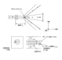
- FIG. 5 shows an operation principle for fine particle sorting in the present technology.
- the microparticle-containing sample liquid flows in the direction of the arrow in FIG. 5 as a sample flow from the inlet portion of the microparticle sorting microchip, and is generated as a result of light being irradiated to the microparticles flowing through the main channel.
- it is necessary to pass the microparticles accurately and one by one through the focal position of the light irradiation.
- sample core the flow in the central portion
- the sorting section which is a region where the sorting operation is performed, it is branched into one particle sorting channel and two waste channels, and the sorting suction in FIG. 5 is performed so that minute particles do not enter from the gate flow.
- the microparticles determined to be sorted based on the scattered light and / or fluorescence information generate a minute negative pressure by rapidly deforming the pressure chamber by the actuator, and the sorting unit (three branches) Do the suction operation from point) and pour it into the particle sorting channel.
- the suction amount (volume) for sorting is small, high speed operation is possible and high throughput can be obtained as sorting processing. It is. However, if the amount of suction is too small, the gate flow responsible for preventing mixing cannot be overcome, the fine particles to be sorted cannot be sucked, and the sorting operation cannot be achieved. Therefore, in order to achieve the sorting performance with robustness while maintaining the high throughput of the sorting process, the velocity (V) of the flowing individual microparticles is accurately detected and adjusted to the individual cells. Therefore, it is necessary to execute the sorting operation at the optimum timing (T) and the optimum suction amount (D).
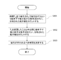
- Particle number counting step S301 Particle count process of FIG. 6 S301, the microparticles suction flow predetermined suction force suction by path D 0 at the time when the predetermined time T 0 has elapsed since the fine particles have passed through the predetermined position of the main flow path It is performed under the condition that it is performed at. Under this condition, a microparticle sorting procedure is executed in the microchip, and the number of microparticles sucked into the microparticle suction channel as a result of executing the sorting procedure is counted.
- a time point at which the fine particles pass is detected at a predetermined position of the main flow path through which the liquid containing the fine particles flows.
- the predetermined position on the main flow path may be a position where the passage of fine particles can be detected.
- the predetermined position may be, for example, in a detection region on the main channel, and is, for example, a light irradiation position.
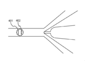
- FIG. 7 is an enlarged view of the sorting unit 107.
- two light beams 401 and 402 are irradiated in the detection region perpendicular to the traveling direction of the particles.
- the irradiation interval between the two lights 401 and 402 is, for example, 20 to 200 ⁇ m, preferably 30 to 150 ⁇ m, and more preferably 40 to 120 ⁇ m.
- the wavelengths of these two lights may be different or the same.
- the predetermined position may be, for example, the irradiation position of the light 402 on the microparticle suction channel side of the two lights, or may be the irradiation position of the other light 401.
- microparticles are sucked from the main channel into the microparticle suction channel with a predetermined suction force by the microparticle suction channel.
- the suction is performed when a predetermined time T 0 has elapsed from when the predetermined position is passed.
- the predetermined time T 0 from when the predetermined position is passed may be appropriately set by those skilled in the art.
- the size of the microchip in particular, from the light irradiation region on the main flow path of the microchip to the entrance of the orifice portion. And / or the flow rate of the particles.
- the distance can be, for example, the distance from the light irradiation position on the fine particle suction flow channel side to the entrance of the orifice portion among the two lights.
- the distance is, for example, 300 ⁇ m to 1500 ⁇ m.
- the time T 0 reaches any position in the region where the microparticles are sucked into the microparticle suction channel when the suction is performed with the suction force D 0 from the time when the predetermined position is passed. It is the time to the point. Alternatively, it may be the time from the time when the predetermined position is passed to the time before reaching the area.
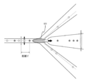
- FIG. 8 is an enlarged view of the sorting unit 107.
- a region 501 that extends in an elliptical shape from the entrance of the microparticle suction channel toward the irradiation region is sucked by the suction force D 0 , the microparticles are sucked into the microparticle suction channel. It is an area.
- the time from passing through the light irradiation position to the point where advanced particles the distance Y may be adopted as the time T 0.
- the time T elapses the particles reach the region.
- the time from passing through the light irradiation position to the point where particles reach in any position within this area may be adopted as the time T 0.
- the velocity of the particles in the flow path can be taken into account as needed.
- the speed is appropriately measured by a method known to those skilled in the art. For example, as shown in FIG. 7, when two light irradiation positions 401 and 402 are provided, it took a distance between the two irradiation positions and the passage between the two irradiation positions. Based on the time, the velocity of the particles in the flow path is calculated. By such a calculation method, the velocity of the particles can be calculated with higher accuracy. In addition, the suction conditions are better optimized by calculating the particle velocity with high accuracy.
- the distance from the predetermined position is calculated from the speed and the elapsed time.
- the distance Y from the predetermined position may be used as a variable. That is, in another embodiment of the present technology, the microparticles when in a particle counting step, microparticles progressed toward the fine particle suction flow path from a predetermined position by a predetermined distance Y 0 of the main road Under the condition that suction by the suction channel is performed at a predetermined suction force D 0 , a microparticle sorting procedure is executed in the microchip, and as a result of executing the sorting procedure, suction is performed in the microparticle suction channel. The number of microparticles taken is counted.
- the distance from the predetermined position at which suction by the microparticle suction channel is to be performed is determined. That is, in the present technology, the distance from the predetermined position where the suction should be performed is optimized instead of the timing when the suction should be performed. That is, instead of the time T, the distance Y from the predetermined position may be used as a variable.
- the suction by the fine particle suction flow path with the predetermined suction force D 0 is performed, for example, by making the inside of the fine particle suction flow path have a negative pressure.
- the negative pressure is set by an actuator such as a piezo element. Since between the driving voltage of the suction force D 0 and the piezoelectric element there is a predetermined relationship, by adjusting the driving voltage of the piezoelectric element, the suction force D 0 can be adjusted. Adjustment of the driving voltage of the piezo element may be performed by means known to those skilled in the art.
- the microparticle sorting procedure is, for example, the above-described 1. This can be carried out using the microparticle sorting apparatus equipped with the microchip described in the above. Refer to the specification of Japanese Patent Application No. 2017-102694 for details of the configuration of the microparticle sorting apparatus.
- a sample liquid containing a known number of microparticles can be used.
- the number of fine particles may be appropriately set by those skilled in the art, and is, for example, 10 to 1000, particularly 30 to 500, and more particularly 50 to 300.
- a sample liquid containing a known number of microparticles is introduced from the sample liquid inlet 101 and proceeds through the sample liquid flow path 102, and the sheath liquid is introduced from the sheath liquid inlet 103. And proceed through the sheath fluid flow path 104.
- the sample liquid and the sheath liquid merge to form a laminar flow, and the laminar flow flows through the main channel 105 toward the sorting unit 107.
- the laminar flow is irradiated with light in the detection region 106. As the microparticles pass through the detection region, scattered light and / or fluorescence is generated from the microparticles.
- suction with the suction force D 0 is performed when the predetermined time T 0 has passed since the minute particle passed through the predetermined position. For example, in a microparticle sorting procedure using a sample liquid containing 100 microparticles, suction is performed for each microparticle, that is, suction is performed 100 times.
- the number of fine particles sucked into the fine particle suction channel is counted.
- the number of microparticles sucked into the microparticle suction channel as a result of performing the microparticle sorting procedure on a known number of microparticles is counted.
- the counting may be performed by means known to those skilled in the art, or may be performed in a detection region provided in the microparticle suction channel.
- Counting the number of the fine particles can be performed at a predetermined position in the fine particle suction channel. For example, the number of microparticles is counted by detecting passage of a predetermined position in the microparticle suction channel.
- An example of the detection region provided in the fine particle suction channel is, for example, a light irradiation region 202 shown in FIG. As shown in FIG. 2, when the microparticles pass through the light irradiation region 202 provided in the microparticle suction channel, scattered light and / or fluorescence is emitted from the microparticles. By detecting the scattered light and / or fluorescence, the number of microparticles sucked into the microparticle suction channel is counted.
- the fine particles may be appropriately selected by those skilled in the art.
- the microparticles may include biological microparticles such as cells, microorganisms, and liposomes, and synthetic particles such as latex particles, gel particles, and industrial particles.
- biological microparticles such as cells, microorganisms, and liposomes
- synthetic particles such as latex particles, gel particles, and industrial particles.
- synthetic particles particularly beads for optimizing suction conditions are used as the microparticles, and in the present technology, they can be used as the adjusting microparticles.
- Such synthetic particles are more preferred for the method of the present technology because they are more readily available than biological microparticles.
- the biological microparticles include chromosomes, liposomes, mitochondria, organelles (organelles) that constitute various cells.
- the cells include animal cells (such as blood cells) and plant cells.
- the microorganism examples include bacteria such as Escherichia coli, viruses such as tobacco mosaic virus, and fungi such as yeast.
- the biological microparticles also include biological macromolecules such as nucleic acids, proteins, and complexes thereof.
- the synthetic particles may be particles made of, for example, an organic or inorganic polymer material or metal.
- the organic polymer material examples include polystyrene, styrene / divinylbenzene, and polymethyl methacrylate.
- the inorganic polymer material examples include glass, silica, and a magnetic material.
- the metal include gold colloid and aluminum.
- the shape of the microparticles may be generally spherical or substantially spherical, or may be non-spherical.
- the size and mass of the microparticles are appropriately selected by those skilled in the art depending on the size of the microchip channel.
- the size of the channel of the microchip is appropriately selected depending on the size and mass of the microparticles.
- the microparticle can be attached with a chemical or biological label, such as a fluorescent dye, as necessary.
- the label makes it easier to detect the microparticles.
- the label to be attached can be appropriately selected by those skilled in the art.
- the microchip used in the method of the present technology is manufactured by a method known in the art.
- the microchip used in the method of the present technology is, for example, the above described 1-1. It can be manufactured by bonding two substrates on which a flow path as described in the microchip for sorting microparticles is formed.
- the flow path may be formed on both of the two substrates, or may be formed only on one of the substrates. In order to more easily adjust the position at the time of bonding the substrates, the flow path can be formed only on one of the substrates.
- a material for forming a microchip used in the present technology a material known in the art can be used. Examples include, but are not limited to, polycarbonate, cycloolefin polymer, polypropylene, PDMS (polydimethylsiloxane), polymethyl methacrylate (PMMA), polyethylene, polystyrene, glass, and silicon.
- polymer materials such as polycarbonate, cycloolefin polymer, and polypropylene are particularly preferable because they are excellent in processability and can be manufactured at low cost using a molding apparatus.
- Step S302 for repeating the particle number counting step the particle number counting step is repeated while changing the time from when the fine particles pass through a predetermined position of the main channel to when the suction is performed.
- the particle number counting process is repeated in the same way except that the T 0 is changed to a longer and / or shorter various times T n .
- the time T n is appropriately set by those skilled in the art in consideration of, for example, the size of the microchip, a region where the suction force reaches when a predetermined suction force is applied, and / or tolerance.
- step S302 to repeat that particle count step for each of the various time T n is made, the particle count results for each of the various time T n is obtained.
- the various times T n may be the respective times when the T 0 is increased and / or decreased stepwise at a predetermined rate.
- the predetermined ratio is, for example, 0.01% to 5%, particularly 0.05 to 2%, more particularly 0.1 to 1%.
- the number of steps for increasing and / or decreasing T 0 is, for example, 5 to 50 steps, particularly 7 to 40 steps, and more particularly 10 to 30 steps.
- the various times T n are (T 0 + T 0 ⁇ 0.2%), (T 0 + T 0 ⁇ 0.2% ⁇ 2), (T 0 + T 0 ⁇ 0.2% ⁇ 3),..., And (T 0 + T 0 ⁇ 0.2% ⁇ 20), and (T 0 ⁇ T 0 ⁇ 0.2%), (T 0 ⁇ T 0 ⁇ 0.2% ⁇ 2), (T 0 ⁇ T 0 ⁇ 0.2% ⁇ 3),..., And (T 0 ⁇ T 0 ⁇ 0.2% ⁇ 20).
- the T 0 including, at each elapsed time of 41 (1 + 20 + 20) in total, the procedure microparticle sorting may be performed.
- the number of steps for increasing T 0 and the number of steps for decreasing T 0 may be the same or different. Further, the various times T n may be only those obtained by increasing the T 0 , or may be only those obtained by decreasing the T 0 . The number of steps for increasing T 0 and the number of steps for decreasing T 0 may be appropriately set by those skilled in the art. Also, for each of the various time T n, a plurality of times the particle count process, for example 2-5 times, may be particularly carried out 2-3 times.
- step S302 Particle count process performed in step S302 to repeat above, except for changing the T 0 longer and / or more short various time T n is the same. Therefore, for the description of the particle number counting step, see (1) above.
- Step S303 for determining the time during which suction should be performed the fine particle suction is performed based on the number of fine particles counted in the particle number counting step S301 or in the particle number counting step S301 and the repeating step S302.
- the elapsed time from when the predetermined position is to be sucked by the flow path is determined.
- the determination is automatically performed by a control unit that executes a predetermined program.
- the time T when the number of fine particles counted in the particle number counting step S301 and the repeating step S302 is the largest is determined as the elapsed time for the suction.
- an arbitrary time out of the plurality of times may be determined as the elapsed time during which the suction should be performed, or the plurality of times
- a central value of the time may be determined as an elapsed time during which the suction should be performed.
- FIG. 5 is a schematic diagram showing a situation in the flow channel when the fine particle sorting procedure is performed.
- a region 601 that expands in an elliptical shape from the entrance of the microparticle suction channel toward the irradiation region is sucked with the suction force D 0 , the microparticles are sucked into the microparticle suction channel. It is an area.
- the predetermined position is a position farther from the fine particle suction flow path among the two light irradiation positions.
- the fine particle 602 that has passed through the predetermined position advances by a distance Y 0 from the predetermined position when the predetermined time T 0 has elapsed, and is at the position shown in FIG.
- the microparticles 602 are within region 601 Therefore, it is sucked into the fine particle suction channel. As shown in FIG.
- the minute particles are theoretically in the region 601 when the predetermined time T 0 has elapsed after the minute particles have passed the predetermined position. However, it may not be sucked into the microparticle suction channel due to factors such as the state of the laminar flow being formed, the shape of the particles, and / or the actual suction force.
- the microparticles when performing suction in T i with increased time T 0, the microparticles are in the position 603, for example. Even if the suction is performed with the suction force D 0 in the position 603, the fine particles are not drawn into the fine particle suction flow path because they are outside the region 601. In FIG. 9, when the suction is performed at T j where the time T 0 is decreased, the fine particles are at the position 604, for example. Even if the suction is performed at the position 604 with the suction force D 0 , the fine particles are not drawn into the fine particle suction flow path because they are outside the region 601. Note that, as shown in FIG.
- the minute particles are theoretically outside the region 601 when the time T i or T j elapses after the minute particles pass the predetermined position. However, it may be sucked into the microparticle suction channel due to factors such as the state of the laminar flow being formed, the shape of the particles, and / or the actual suction force.
- a graph in which the T 0 is changed to various times and the number of particles counted at each time is plotted against time is shown on the right side of FIG. As shown in the graph, the number of particles counted is the largest when the elapsed time is within a predetermined range.
- An arbitrary time within the predetermined range may be determined as an elapsed time for the suction to be performed, or a central value within the predetermined range is determined as an elapsed time for the suction to be performed. Also good.
- a success rate of suction of the microparticles into the suction flow path is calculated based on the number of microparticles counted in the particle number counting step and the repetition step, and based on the success rate
- the elapsed time from when it passes through the predetermined position to be suctioned by the fine particle suction channel is determined.
- the elapsed time when the success rate is the highest may be determined as the elapsed time from when the predetermined position is passed through which the suction by the fine particle suction flow path should be performed.
- an arbitrary time may be determined as an elapsed time during which the suction should be performed from among a plurality of elapsed times in which the success rate is equal to or greater than a predetermined value, or of the plurality of elapsed times
- the median value may be determined as the elapsed time during which the suction should be performed.
- the method for optimizing the suction conditions of the microparticles of the present technology may further include a second repetition step in which the suction force is changed and the particle number counting step and / or the repetition step is repeated.
- the optimization method of the present technology includes the second repeating step, in the determining step, the number of microparticles counted in the particle number counting step and / or the repeating step and the second repeating step Based on the above, the elapsed time from when the microparticles pass through the predetermined position and the suction force to be applied to the suction of the microparticles to be suctioned by the microparticle suction channel are determined.
- steps S401 and S402 are the same as in 2-1. This is the same as steps S301 and S302 described in the basic suction condition optimization method I. Therefore, the description about these processes is omitted.
- Second repetition step S403 of repeating the particle number counting step In the second repeat step S403 in FIG. 10, except for changing the suction force D 0 to larger and / or smaller various suction force D n in the same way, repeated the particle count step and / or said The process is repeated.
- the second repeat step S403 in FIG. 10 except for changing the suction force D 0 to less various suction force D n in the same way is repeated particle count step S401 and repeats step S402 .
- the suction force D n considers factors such as the specifications of the suction means provided in the fine particle suction flow path, the size of the microchip, the area where the suction force reaches when a predetermined suction force is applied, and / or tolerances. Thus, it is appropriately set by those skilled in the art.
- step S403 to repeat that the particle count process is performed for each of the various suction force D n, particle count results for each of the various suction force D n is obtained.
- the various suction forces D n are the suction forces obtained by increasing or decreasing the D 0 stepwise at a predetermined rate.
- the predetermined proportion can be, for example, 0.01-30%, in particular 0.1% -25%, more particularly 1-20%, even more particularly 1-10%.
- the number of steps for increasing or decreasing D 0 is, for example, 3 to 20 steps, particularly 4 to 15 steps, more particularly 5 to 10 steps.
- the various suction forces D n are (D 0 -D 0 ⁇ 20%), (D 0 -D 0 ⁇ 20% ⁇ 2), (D 0 -D 0 ⁇ 20% ⁇ 3), and (T 0 -T 0 ⁇ 20% ⁇ 4).
- the D 0 including, in each of the five attraction in total, the procedure microparticle sorting is performed.
- the number of steps for increasing D 0 and the number of steps for decreasing D 0 may be the same or different.
- the various suction forces D n may be only those obtained by increasing the D 0 , or may be only those obtained by decreasing the D 0 .
- the number of steps to reduce the number and the D 0 stage to increase the D 0 may be appropriately set by the value of the D 0.
- the particle number counting step may be performed a plurality of times, for example, 2 to 5 times, particularly 2 to 3 times.
- Step S404 of determining the time at which suction is to be performed and / or the suction force to be applied In step S404 for determining the time for suctioning and / or the suction force to be applied in FIG. 10, the number of microparticles counted in the particle number counting step S401, the repeating step S402, and the second repeating step S403. Based on the above, the elapsed time from when the predetermined position is passed and / or the suction force to be applied to the suction of the microparticles to be suctioned by the microparticle suction flow path are determined. As a result, the time point at which the microparticles are to be suctioned and the suction force to be applied are optimized. The determination is automatically performed by, for example, a control unit that executes a predetermined program.
- the determining step S404 for example, the time T and the suction force D when the number of fine particles counted in the particle number counting step S401, the repetition step S402, and the second repetition step S403 are the largest and the suction force is the smallest are obtained. , The elapsed time at which the suction should be performed and the suction force to be applied.
- the suction force D that minimizes the suction force is determined as the suction force to be applied from the combination of the time T n and the suction force D n when a predetermined number or more of fine particles are counted, and A central value among a plurality of elapsed times in which fine particles are counted by a predetermined number or more with the determined suction force may be determined as an elapsed time for which suction is to be performed.
- the suction is performed for any combination of time and suction force from among these combinations.
- the minimum value of the suction force is determined as the suction force to be applied, and A central value among a plurality of times may be determined as an elapsed time during which the suction is to be performed.
- FIG. 9 is a schematic diagram showing a situation in the flow channel when the fine particle sorting procedure is performed as described above.
- the micro particles 602 are: In the region 601, it is sucked into the fine particle suction channel.
- FIG. 11 shows that when the predetermined time T 0 or T 1 has passed since the minute particles passed through the predetermined position on the main channel, the suction by the minute particle suction channel is smaller than the suction force D 0. under the condition that performed by the force D n, it is a schematic diagram showing the status of the flow path when doing the procedure microparticle sorting.
- region 801 extends into an elliptical shape from the entrance of the fine particle suction channel towards the irradiation area, fine particles are attracted to the fine particle suction passage to aspiration by suction force D n It is an area.
- the predetermined position is a position farther from the fine particle suction flow path among the two light irradiation positions.
- the minute particles 802 that have passed through the predetermined position are moved by the distance Y 0 from the predetermined position when the predetermined time T 0 has elapsed, and are at the position shown in FIG.
- the microparticles 802 are in the region 601, so Inhaled.
- the microparticles 802 are outside the region 801, so that the microparticle suction flow It is not sucked into the street.
- the minute particles 803 that have passed through the predetermined position are moved by the distance Y 1 from the predetermined position when the predetermined time T 1 elapses, and are at the position shown in FIG.
- the microparticles 803 are within region 801 Therefore, it is sucked into the fine particle suction channel.
- the smaller the suction force the narrower the region where the suction force reaches.
- the success rate of suction of the microparticles into the suction channel is based on the number of microparticles counted in the particle number counting step, the repetition step, and the second repetition step. Based on the calculated success rate, an elapsed time from when passing through the predetermined position and / or a suction force to be applied to be suctioned by the fine particle suction flow path is determined. For example, the time T and the suction force D when the success rate is the highest and the suction force is the smallest are determined as the elapsed time during which the suction should be performed and the suction force to be applied.
- the time T and the suction force D at which the suction force is minimized are used as the elapsed time and application for which the suction is performed. It may be determined as a suction force to be performed.
- any combination of time and suction force is selected from the combinations. It may be determined as the elapsed time to be performed and the suction force to be applied.
- the minimum of the suction force is determined as the suction force to be applied, and A central value among a plurality of times may be determined as an elapsed time during which the suction is to be performed.
- the suction force is stepwise reduced at a predetermined ratio from the suction force D 0, and the second The repeating step 2 can be performed until a result is obtained in which the number of microparticles sucked into the microparticle suction channel becomes zero at any elapsed time.
- the suction force increased at a predetermined rate from the suction force when a result of 0 is obtained at any elapsed time is applied to the suction of the microparticles. It can be determined as the power of attraction.
- the suction force can be automatically optimized. Status changes in the flow path when the suction force was reduced from the suction force D 0 is as described above with reference to FIGS. 9 and 11.
- the predetermined ratio and the number of stages of reduction are as described in (1) above.
- the situation in the channel will be described below with reference to FIG. 12 in the case where a result is obtained in which the number of microparticles sucked into the microparticle suction channel is zero at any elapsed time.
- the solid line and the dotted line in the flow path indicate the positions through which the fine particles pass.
- a region 901 from the entrance of the fine particle suction channel are slightly spread toward the illuminated region, the suction force microparticles suction passage to aspiration in smaller attraction force D Z than D 1 This is a region where fine particles are sucked.
- the region 901 does not overlap with either the solid line or the dotted line indicating the position through which the microparticles pass.
- a graph in which the T 0 is changed to various times and the number of particles counted at each time is plotted against time is shown on the right side of FIG. As shown in the graph, the count number is 0 regardless of the elapsed time.
- the second repetition step is performed until a result is obtained that the number of microparticles sucked into the microparticle suction flow path becomes zero at any elapsed time. That is, the second repetitive step is terminated when a result is obtained that the number of microparticles sucked into the microparticle suction flow path becomes zero at any elapsed time.
- a suction force increased at a predetermined rate from the suction force when a result of 0 is obtained in any of the elapsed times should be applied to the suction of the microparticles. Determined as suction force.
- the suction force that is increased from the suction force when a result of 0 is obtained at any elapsed time is determined as the suction force to be applied to the suction of the microparticles is determined by the second method.
- D 0 when D 0 is decreased by 1 to 10%, from the suction force that results in 0 at any elapsed time, for example, (the reduction ratio (ie, 1 to 10%) ⁇ 1) to A value obtained by adding the value of (the reduction ratio ⁇ 5) to the suction force that obtained a result of 0 in any elapsed time is determined as the suction force to be applied.
- the reduction ratio ie, 1 to 10%
- the sample core is carried out in a very small state with respect to the sheath flow. That is, it is assumed that the velocity of the microparticles flowing inside the sample core is constant, and suction is performed so as to obtain an optimal microparticle fractionation timing and a fractional suction amount (actuator driving force) of the microparticle-containing sample liquid. Yes. In this way, if there is no difference in velocity between the microparticles in the sample core, it is possible to automatically calculate the best sorting timing for the velocity of the microparticles even if the velocity of the sheath flow changes. It has become.
- the concentration adjustment of the microparticle-containing sample liquid is generally performed as a pretreatment for setting the microparticle-containing sample liquid in the microparticle sorting apparatus described later, so the concentration adjustment is performed while the apparatus is processing. Without adjustment, the number of microparticles passing in one second (hereinafter, also referred to as “sample event rate”) is adjusted by the amount of the sample solution fed.
- the size of the sample core in the main flow path of the microchip for sorting microparticles is determined by the volume of the sample liquid containing the microparticles, and even when the sample liquid has a low microparticle concentration, the sample event rate is increased. For this, it is necessary to increase the amount of the microparticle-containing sample liquid, and the size of the sample core also increases.
- FIG. 13 shows a case where the flow rate of the microparticle-containing sample liquid is small and the sample core size is small
- FIG. 14 shows a case where the flow rate of the microparticle-containing sample liquid is large and the sample core size is large.
- Fine particle fractionation is a method of sucking particles by operating a pressure chamber and generating minute negative pressure, so if the sample core size increases, the sample suction port located at the center of the main channel A large amount of particles that pass through a position far from the center of the sample core cannot be stably suctioned with a preparative suction amount (driving force of the actuator) when the sample core size is small. In such a situation, it is impossible to achieve good sorting performance if the sorting suction amount remains fixed, and optimum control of the suction amount adapted to the passing position of the fine particles is required. Therefore, this technology has developed the following suction condition optimization method.
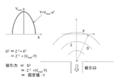
- each microparticle is twice as fast as the average flow velocity, but when the sample core size is large, the area through which the microparticles pass through the main channel is also large, so the microparticle velocity Diffuses and the microparticle velocity decreases in inverse proportion to the distance from the center of the main channel.
- V individual velocity of a group of microparticles at a certain time (for example, 1 second)
- V ave average velocity of the group of microparticles
- V max the fastest of the individual microparticles in the group of microparticles
- V min Individual microparticle velocity that is the lowest among the individual microparticles in the group of microparticles.
- the fixed time is a fractionated from a predetermined position of the main channel. It can be set as the time for the microparticles to pass to the position where they do. This time can be set as time t.
- V ave For example, by normalizing (V / V ave ) individual microparticle velocities using the average flow velocity: V ave , it is possible to use it as an index indicating the distance from the center of the main channel. In doing so, the individual V / V ave is calculated using the data of velocity V of as many individual microparticles as possible, preferably the data of the velocity V of all the microparticles that pass almost in the vicinity of the center of the flow path. Is preferred. Thereby, a more suitable approximate value of the center flow velocity of the sample core can be obtained. In addition, even if turbulent flow due to the microparticle microchip or pulsating flow due to actuator drive occurs, the center flow velocity of the sample core can be grasped more accurately than before. .
- the distance from the suction port (microchip for sorting microparticles of the present technology) shown in FIG. 15 is Z (fixed value) in the flow direction, and X is the distance from the center as described above.
- the Y corresponds to the velocity V of each individual microparticle, so if the velocity V of each individual microparticle is substituted into the above equation 4, a desired suction force, that is, a desired actuator drive. Force can be calculated.
- V / V ave is used in the present technology, since the measured speed of the individual microparticles is normalized by the V ave as described above, the same coefficient can be used regardless of the speed.
- the driving force of the actuator at the time of suction is controlled to be inversely proportional to V / V ave based on the V / V ave , the fine particles (velocity V max ) at the center of the sample core are separated from the center of the sample core with a small driving force.
- the particles (velocity V min ) can be sucked with a large driving force, and the sorting suction force adapted to the particle position from the sorting suction port can be individually controlled.
- a step of controlling the driving of the actuator in inverse proportion to the index calculated by V / V ave may be included as the average velocity V ave of the microparticles in the predetermined time.
- the fine particles when flowing through the substantially central portion of the fine particle-containing sample solution, the maximum velocity V max in fine particles in the fixed time, the driving of the actuator in said V max is V ave If the pressure is made smaller than before and the pressure in the pressure chamber is increased, the suction force acting on the fine particles is lowered. Using V / V max as an index, the pressure is controlled to be inversely proportional.
- the fine particles when flowing through the substantially outermost fine particle-containing sample solution, said a minimum speed V min in the microparticles at a fixed time, the actuator of the driven V ave at the V ave If the pressure in the pressure chamber is reduced and the pressure in the pressure chamber is reduced, the suction force acting on the fine particles increases.
- the maximum flow rate can be maintained by increasing the flow rate of the sample liquid even when the microparticle concentration is low. And deterioration of sorting performance can be suppressed.
- concentration treatment a small amount of fine particles to be collected is low, but a large amount of fine particles are processed
- a purification treatment that prioritizes purity in order to make the purity of particles to be collected very high Even in the sorting state in which the size of the sample core is large, it is possible to maintain good fine particle sorting characteristics.
- Embodiment of Fine Particle Suction Control> As one embodiment of the present technology, for example, In a microchip for sorting microparticles, including a main channel through which a sheath liquid and a microparticle-containing sample liquid flow, and a pressure chamber that sucks microparticles by driving an actuator, The sheath liquid and the adjustment microparticle-containing sample liquid are allowed to flow through the main channel, and the time when the adjustment microparticles pass at a predetermined position of the main channel is detected, and the velocity V data of the adjustment microparticles is obtained.
- Process to acquire A step of sucking the fine particles for adjustment from the main flow path to the pressure chamber with a predetermined suction force; A particle number counting step for counting the number of fine particles for adjustment sucked into the pressure chamber, and a time from when the fine particle for adjustment passes a predetermined position of the main flow path until the suction is performed, A step of determining an elapsed time from when the predetermined position is passed, based on the counted number of adjustment microparticles; A larger amount of the sample liquid than the adjustment microparticle-containing sample liquid is passed through the main channel, and the time when the adjustment microparticles pass at a predetermined position of the main channel is detected to detect the individual adjustment microparticles.
- a method of controlling the pressure in the pressure chamber in inverse proportion to the index calculated by V / V ave , and performing the fractionation of the fine particles for adjustment into the pressure chamber. can be optimized.
- the timing at which suction is performed by incorporating the velocity data acquisition step of the fine particles and the drive control step of the actuator that controls the pressure of the pressure chamber, and / or The magnitude of the applied suction force is further optimized, and the sorting performance of the fine particles can be further enhanced.
- the fine particle velocity data acquisition step and the actuator drive control step may be incorporated into the sorting means in step S301 and / or the sorting procedure in step S302.
- the actuator drive is increased and / or decreased, and the number of particle counts of the already adjusted fine particles is approximately the same as the total number of the adjusted fine particles. It may include calculating a constant.
- microparticle velocity data acquisition step and actuator drive control step may be incorporated. Referring to FIG. 10, if any of the steps S401, S402, and S403, or a combination of the steps, or a fractionation procedure in all steps, the velocity data acquisition step of microparticles and the drive control step of the actuator are incorporated. Good.
- steps S301 to S303 in FIG. 6 are first performed, and then the velocity data acquisition step of the microparticles and the actuator are performed in one of the steps S401, S402, and S403 in FIG. Steps S401 to S403 incorporating a drive control step may be performed, and finally step S404 may be performed.
- steps S301 to S303 in FIG. 6 are first performed, then steps S401 to S404 in FIG. 10 are performed, and any one of steps S301, S302, S401, S402, and S403, or an appropriate combination thereof is performed.
- Embodiment I As a specific example, an example of the adjustment procedure of the method for optimizing the suction conditions for the fine particles of the present technology will be described.
- the driving force and operation of the actuator related to the pressure chamber of the microchip for microparticle sorting in the method for optimizing microparticle suction according to the present technology for example, it is possible to detect scattered light by light irradiation. Microbeads are used as the fine particles for adjustment. Then, based on the information on the behavior of the adjustment microbeads obtained from the scattered light, the fine particle sorting timing T and the suction force D are optimized in the following adjustment procedures 1 to 15. A piezoelectric element was used as the actuator.
- Adjustment procedure 1 Set the microparticle sorting microchip and the adjustment microbead in the microparticle sorting device, send the sheath liquid, and start the automatic adjustment program.
- Adjustment procedure 2 After degassing the microparticle sorting tip and the microchannel of the microparticle sorting device with the sheath liquid, the microbeads for adjustment are flowed (the sample core size is kept very small). The position of the chip is adjusted (X axis, Y axis, Z axis) so that the signal intensity (scattered light or fluorescent signal) from the particles is maximized.
- Adjustment procedure 3 Scattered signals at the laser detection unit and the post-sorting detection unit are acquired by the optical system shown in FIG. 5, and the time difference (passed from a predetermined position in the main flow path) that passes through the two spots of the laser sorting unit.
- the individual particle velocity: V is calculated from the time t) when the microparticles pass to the position to be taken.
- Adjustment Procedure 6 actuator driving force: D 1 remains fixed, the distance: Y while changing the swept allowed prep time, and detects a preparative spent grain at that time to obtain a count number distributions.
- Adjustment procedure 7 Actuator driving force: D 2 in which the fractionation suction amount is made smaller than that in the adjustment procedure 5. The same detection operation as that in the adjustment procedure 6 is performed at D 2 , and the optimum sorting distance Y 2 (sorting time) is recorded. .
- Actuator driving force has a small amount of suction intake adjustment procedure 8 minutes: at D 2, performs the same detection operation and adjustment procedure 6, record the optimum preparative distance Y 2 (prep time).
- Actuator driving force count becomes zero adjustment procedure 10 prep spent grain: large or should than D 3 actuator driving force: D 2 and preparative distance Y 2 a (prep time) as the optimal preparative parameters Adopt and conduct sorting operations.
- Adjustment procedure 11 The adjustment beads, which are several times (for example, 10 times) the amount of sample supplied in adjustment procedure 2, are sent, and the optical signals shown in FIG. And the individual particle velocity: V is calculated from the time difference between the two spots of the laser sorting unit.
- V ave An average particle velocity (for example, 1 second) for a certain period of time is defined as V ave, and this particle velocity: V is divided by V ave to obtain a coefficient that is inversely proportional to the particle position from the center of the sample core.
- Adjustment procedure 14 If the number of times of fractionation and the count of the fractionated particles are almost 100% under the above conditions, the adjustment is completed. If 100% is not reached, the value of K is searched for ⁇ . Obtain a distribution of pre-sorted particle counts.
- Adjustment procedure 15 The K value of the center value of the distribution in which the pre-sorted particle count is close to 100% or has obtained 100% is adopted as the preparative condition.
- Adjustment procedure 16 Stops the sample feeding, cleans the flow path through which the sample flows with the sheath liquid and other flow paths, and ends the automatic adjustment.
- the optimal fractionation timing: T and the suction amount: D are adjusted to sort the microparticles to be collected. be able to. Furthermore, even when the sample core is large and the microparticle position in the main flow path of the microchip for sorting microparticles is different, the suction force can be automatically controlled to the optimum suction amount suitable for the microparticle position. Even if the amount of sample liquid fed increases or decreases, it is possible to maintain good sorting performance. Therefore, a state with high robustness can be maintained even in a microparticle sorting system described later.
- Embodiment II As a more specific example, it is possible to optimize the suction conditions for the fine particles of the present technology according to the flowchart shown in FIG. Hereinafter, each process of FIG. 16 will be described. A piezoelectric element was used as the actuator.
- Process 1 Set conditions for feeding sheath liquid and microparticle-containing sample liquid to a microparticle sorting apparatus equipped with the program described below.
- This liquid feeding condition can be defined in advance so that the size of the sample core is minimized.
- Process 2 Place the microchip for sorting microparticles and the microbead for adjustment in the microparticle sorting machine.
- Process 3 The automatic adjustment parameters for optimizing the fine particle suction conditions incorporated in the program in advance are reset as necessary.
- Process 4 On the user interface (eg, GUI) such as a touch panel, click the automatic adjustment start button of the microparticle sorting device.
- GUI graphical user interface
- Process 5 Sends sheath fluid and starts an automatic adjustment program. With the sheath liquid, the flow path of the set microparticle sorting microchip is degassed.
- Process 6 The sample loader for supplying the microparticle-containing sample liquid provided in the microparticle sorting apparatus is brought into a pressurized state, and the liquid supply of the adjusting beads is started.
- Process 7 Wait until the delivery of the sample liquid containing fine particles is stabilized. For example, it may be programmed to wait for one minute in advance. Then, the position adjustment (X axis, Y axis, Z axis) of the microchip for sorting microparticles is performed so that the signal intensity of scattered light or fluorescence from the microparticles is maximized.
- Process 9 Sorting operation timing calculated in Process 8: Actuator is driven at T.
- Process 10 The microbeads for adjustment collected are detected by, for example, a scattered light detection system, and the number of fractions is measured.
- Process 12 Based on the data obtained by repeating the process 9 to the process 11 20 times, for example, a sorting timing T at which the number of the adjusted microbeads is the maximum or the center of the maximum value is adopted. .
- the suction force by the driving of the actuator gradually reducing the suction force from D 0, for example D 0 5% discount is carried out by preparative operation in 95% of the suction force that time adjustment that is dispensed into
- the number of microbeads for use is counted by the detection unit after sorting, and the search is continued until the count after sorting becomes zero. Note that the process 9 to the process 13 may be repeated.
- Process 14 When the counter reaches 0 after sorting, that is, search to the limit of the suction force at which suction cannot be performed, the actuator drive voltage two steps before (process 12), ie suction force: D, sorting timing: T is optimal. Adopt as a value.
- Process 15 increase the flow rate of the sample liquid containing fine particles and increase the size of the sample core.
- a coefficient proportional to the microparticle position is set to K, and a coefficient K is applied to the actuator driving voltage (D 2 ⁇ (V / V ave )).
- Process 17 Count the number of preparative microbeads dispensed. Steps 16 and 17 may be repeated until all the adjustment microbeads are acquired. The above processes 15 to 17 are the suction amount correction sequence.
- Process 18 When all the adjustment microbeads have been acquired, the feeding of the microparticle-containing sample liquid is stopped, and the backflow cleaning of the line through which the microparticle-containing sample liquid has flowed is performed. This completes the automatic adjustment sequence.
- Microparticle sorting program> The present technology also provides a fine particle sorting program for causing a computer to realize a function of controlling the fine particle sorting device in order to perform the method for optimizing the suction conditions of the fine particles.
- the fine particle sorting program of this technology is (A) Using a microchip for sorting microparticles, including a main channel through which a sheath liquid and microparticle-containing sample liquid flow, and a pressure chamber for sucking microparticles, Passing the sheath liquid and the microparticle-containing sample liquid through the main channel, detecting the time when the microparticles pass at a predetermined position of the main channel, and acquiring the data of the velocity V of each microparticle; And (F) acquiring data of the average velocity V ave of the microparticles for a certain time, and causing the computer to control the suction force of the pressure chamber in inverse proportion to the index calculated by V / V ave It is a program.
- the program is between (A) and (F), (B) sucking the adjustment microparticles from the main flow path into the pressure chamber with a predetermined suction force; (C) counting the number of the adjustment microparticles sucked into the pressure chamber; D) Based on the time from when the fine particles for adjustment pass through a predetermined position of the main flow channel until the suction is performed and the counted number of fine particles for adjustment, Determining the elapsed time from when the predetermined position is to be sucked, and (E) passing a larger amount of sample liquid than the adjustment microparticle-containing sample liquid through the main channel, Detecting the time point at which the fine particles for adjustment pass at a predetermined position of the main flow path, and acquiring the data of the velocity V of each fine particle for adjustment; May be a program that causes a computer to execute.
- the program may be stored in a recording medium such as a magnetic disk, an optical disk, a magneto-optical disk, or a flash memory, and may be distributed via a network.
- a recording medium such as a magnetic disk, an optical disk, a magneto-optical disk, or a flash memory
- the program can externally perform analysis with a computer attached to the microparticle sorting apparatus, or can be built into the microparticle sorting apparatus and execute analysis. .
- Microparticle sorting system The present technology also provides a system for sorting microparticles that can perform the method for optimizing the suction conditions of the microparticles.
- the system for sorting fine particles A microchip for sorting microparticles, including a main channel through which the sheath liquid and the microparticle-containing sample liquid flow, and a pressure chamber for sucking the microparticles; Velocity data for acquiring the data of velocity V of individual microparticles by passing the sheath liquid and the microparticle-containing sample liquid through the main channel and detecting the time when the microparticles pass at a predetermined position of the main channel.
- An acquisition device A pressure control device for controlling the pressure for sucking the microparticles based on the data of the velocity V of the individual microparticles; It includes a computer in which a program for controlling the pressure is incorporated.
- a computer for example, a computer in which the programs (A) and (F) are incorporated, and the programs (A), (B), (C), (D), (E), and (F) are incorporated.
- a computer may be used.
- this technique can also take the following structures.
- a microchip for sorting microparticles including a main channel through which a sheath liquid and a microparticle-containing sample liquid flow, and a pressure chamber for sucking the microparticles, Passing the sheath liquid and the microparticle-containing sample liquid through the main flow path, detecting a time when the microparticles pass at a predetermined position of the main flow path, and acquiring data of velocity V of each microparticle;
- a method for optimizing the suction conditions of the microparticles including the step of controlling the pressure for sucking the microparticles based on the data of the velocity V of the individual microparticles.
- [2] The average velocity V ave of the fine particles at a certain time, comprising the step of obtaining at least one data of the maximum velocity V max and the minimum speed V min in the individual microparticles, the method described in [1].
- [3] the average speed V ave of the fine particles in the predetermined time, based on the data of the velocity V of at least one of data and the individual microparticles maximum velocity V max and the minimum speed V min in the individual microparticles
- the method according to [2] comprising a step of controlling a pressure for sucking the fine particles.
- microparticle sorting microchip including a main channel through which the sheath liquid and the microparticle-containing sample liquid flow, and a pressure chamber for sucking the microparticles, The sheath liquid and the adjustment microparticle-containing sample liquid are allowed to flow through the main channel, and the time when the adjustment microparticles pass at a predetermined position of the main channel is detected, and the speed V of each individual adjustment microparticle is detected.
- the step of acquiring the velocity V data of the following and the data of the average velocity V ave over a certain period of time Including the step of controlling the pressure of the pressure chamber for sucking the fine particles for adjustment in proportion to the index calculated by V / V ave and sorting the fine particles for adjustment into the pressure chamber, A method for optimizing the suction conditions for fine particles.
- [13] including a step of counting the number of the fine particles for adjustment sucked into the pressure chamber again after the step of performing the separation of the fine particles for adjustment into the pressure chamber; The number of times the adjustment microparticles are sorted into the pressure chamber is compared with the number of particles counted in the adjustment microparticles that have been sorted, and all of the adjustment microparticles are not sorted.
- a microchip for sorting microparticles including a main channel through which the sheath liquid and the microparticle-containing sample liquid flow, and a pressure chamber that sucks the microparticles; Velocity data for obtaining data of velocity V of individual microparticles by detecting the time when the microparticles pass through the main channel through the sheath liquid and the sample solution containing the microparticles and at a predetermined position of the main channel.
- a microchip for sorting microparticles including a main channel through which the sheath liquid and the microparticle-containing sample liquid flow, and a pressure chamber for sucking the microparticles; Velocity data for acquiring the data of velocity V of individual microparticles by passing the sheath liquid and the microparticle-containing sample liquid through the main channel and detecting the time when the microparticles pass at a predetermined position of the main channel.
- An acquisition device A pressure control device for controlling the pressure for sucking the microparticles based on the data of the velocity V of the individual microparticles;
- a system for sorting microparticles comprising: a computer incorporating a program for controlling the pressure.
- a microparticle sorting microchip that includes a main channel through which the sheath liquid and the microparticle-containing sample liquid flow, and a pressure chamber that sucks the microparticles, The sheath liquid and the microparticle-containing sample liquid are allowed to flow through the main channel, and the time when the microparticles pass at a predetermined position in the main channel is detected, and the data of the velocity V of each microparticle and the fixed time.
- a program for sorting microparticles that causes a computer to execute.
- a microchip for sorting microparticles including a main channel through which the sheath liquid and the microparticle-containing sample liquid flow, and a pressure chamber for sucking the microparticles, The sheath liquid and the adjustment microparticle-containing sample liquid are allowed to flow through the main channel, and the velocity data of the adjustment microparticles is acquired by detecting the time when the adjustment microparticles pass at a predetermined position of the main channel.
- the data of the velocity V and the average velocity V ave data of the fine particles for adjustment in a certain time are acquired, and the suction force of the pressure chamber is controlled in inverse proportion to the index calculated by V / V ave , Performing the sorting of the fine particles for adjustment into a pressure chamber;
- a program for sorting microparticles that causes a computer to execute.
Abstract
The present invention provides a technique for further optimizing fine particle suction conditions by using a fine particle separation microchip. This technique provides a method for optimizing fine particle suction conditions by using a fine particle separation microchip that includes: a main flow path through which flow a sheath liquid and a fine particle-containing sample liquid; and a pressure chamber into which the fine particles are sucked. The method includes: a step for causing the sheath liquid and the fine particle-containing sample liquid to flow through the main flow path, detecting points of times at which the fine particles pass a prescribed position of the main flow path, and acquiring data about the speeds V of the individual fine particles; and a step for controlling pressure for sucking the fine particles on the basis of the data about the speeds V of the individual fine particles.
Description
本技術は、微小粒子の吸引条件の最適化方法、微小粒子分取用装置、微小粒子分取用システム及び微小粒子分取用プログラムに関する。より詳細には、フローサイトメータにおいて用いられる微小粒子分取系において、液滴を形成せずに、マイクロチップ内で目的の微小粒子を閉鎖系で分取する技術での、微小粒子の吸引条件の最適化方法、微小粒子分取用装置、微小粒子分取用システム及び微小粒子分取用プログラムに関する。
This technology relates to a method for optimizing the suction conditions of microparticles, a microparticle sorting apparatus, a microparticle sorting system, and a microparticle sorting program. More specifically, in the fine particle sorting system used in the flow cytometer, the fine particle suction condition in the technology for sorting the target fine particles in a closed system in the microchip without forming a droplet. The present invention relates to an optimization method, a microparticle sorting apparatus, a microparticle sorting system, and a microparticle sorting program.
微小粒子を分取するために、これまで種々の装置が開発されてきている。例えばフローサイトメータにおいて用いられる微小粒子分取系において、フローセル又はマイクロチップに形成されたオリフィスから、細胞を含むサンプル液とシース液とから構成される層流が吐出される。吐出される際に所定の振動が当該層流に与えられて、液滴が形成される。当該形成された液滴の移動方向が、目的の微小粒子を含むか含まないかによって、電気的に制御されて、目的の微小粒子が分取される。
Various devices have been developed so far to sort fine particles. For example, in a microparticle sorting system used in a flow cytometer, a laminar flow composed of a sample liquid containing cells and a sheath liquid is discharged from an orifice formed in a flow cell or a microchip. When ejected, a predetermined vibration is applied to the laminar flow to form droplets. The moving direction of the formed droplets is electrically controlled depending on whether the target microparticles are included or not, and the target microparticles are collected.
上記のように液滴を形成せずに、マイクロチップ内で目的の微小粒子を分取する技術も開発されている。
As described above, a technique for separating the target minute particles in the microchip without forming droplets has also been developed.
例えば、下記特許文献1には、「微小粒子を含むサンプル液が通流するサンプル液導入流路と、該サンプル液導入流路にその両側から合流し、前記サンプル液の周囲にシース液を導入する少なくとも1対のシース液導入流路と、前記サンプル液導入流路及びシース液導入流路に連通し、これらの流路を通流する液体が合流して通流する合流流路と、該合流流路に連通し、回収対象の微小粒子を吸引して引き込む負圧吸引部と、該負圧吸引部の両側に設けられ、前記合流流路に連通する少なくとも1対の廃棄用流路と、を有するマイクロチップ。」(請求項1)が記載されている。当該マイクロチップにおいて、目的の微小粒子は吸引によって負圧吸引部へと回収される。
For example, in Patent Document 1 below, “a sample solution introduction channel through which a sample solution containing microparticles flows, and a sample solution introduction channel that joins from both sides of the sample solution introduction channel and introduces a sheath solution around the sample solution” At least one pair of sheath liquid introduction flow paths, a sample liquid introduction flow path and a sheath liquid introduction flow path, and a merge flow path through which the liquid flowing through these flow paths merge and flow, A negative pressure suction part that communicates with the merged flow path and sucks and draws the fine particles to be collected; and at least one pair of waste flow paths that are provided on both sides of the negative pressure suction part and communicate with the merged flow path; A microchip having the above-mentioned (Claim 1). In the microchip, target microparticles are collected by suction into a negative pressure suction part.
また、下記特許文献2には、「主流路を通流する液体中の微小粒子を、前記主流路に連通する分岐流路内に負圧を発生させることにより該分岐流路内に取り込む手順を含み、該手順において、前記主流路と前記分岐流路との連通口に、前記分岐流路側から前記主流路側へ向かう液体の流れを形成させておく微小粒子分取方法。」(請求項1)が記載されている。当該分取方法において、当該主流路側へ向かう液体の流れによって、非分取動作時において非目的粒子又はこれを含むサンプル液及びシース液が分取流路に進入するのを抑制する。また、下記特許文献2には、当該微小粒子分取方法を実施可能な微小粒子分取用マイクロチップも記載されている(請求項9)。
Further, the following Patent Document 2 states that “a procedure for taking microparticles in a liquid flowing through a main channel into the branch channel by generating a negative pressure in the branch channel communicating with the main channel. In the procedure, a fine particle sorting method in which a flow of liquid from the branch channel side to the main channel side is formed at the communication port between the main channel and the branch channel ”(Claim 1). Is described. In the sorting method, the flow of the liquid toward the main channel side suppresses the non-target particles or the sample liquid including the target liquid and the sheath liquid from entering the sorting channel during the non-sorting operation. Patent Document 2 below also describes a microchip for microparticle sorting that can implement the microparticle sorting method (claim 9).
このように、マイクロチップ内で目的の微小粒子を分取する技術では、主流路を流れる液体が目的の微小粒子を含まない場合には当該液体は例えば廃棄用流路へと流れ、主流路を流れる液体が目的の微小粒子を含む場合に当該液体が粒子分取流路内に導かれることで、目的の微小粒子が回収される。
As described above, in the technology for separating the target microparticles in the microchip, when the liquid flowing through the main flow path does not include the target microparticles, the liquid flows, for example, to the disposal flow path, When the flowing liquid includes target microparticles, the liquid is guided into the particle sorting channel, whereby the target microparticles are collected.
マイクロチップ内で目的の微小粒子を分取する閉鎖系の技術において、例えば負圧によって目的の微小粒子が上記粒子分取流路内に吸引されうる。液体が目的の微小粒子を含まない場合は、吸引は行われない。そこで、微小粒子の分取性能を高める為には、吸引が行われるタイミング及び/又は適用される吸引力の大きさが最適化される必要がある。
In a closed-system technology that sorts target microparticles in a microchip, the target microparticles can be sucked into the particle sorting channel by, for example, negative pressure. If the liquid does not contain the desired microparticles, no suction is performed. Therefore, in order to improve the sorting performance of the microparticles, it is necessary to optimize the timing at which suction is performed and / or the magnitude of the applied suction force.
そこで、目的の微小粒子を分取する技術において、微小粒子の分取性能を高めるために、吸引が行われるタイミング及び/又は適用される吸引力の大きさを最適化する開発が行われた(特願2017-102694)。
Therefore, in order to improve the fractionation performance of the microparticles in the technology for fractionating the target microparticles, development has been carried out to optimize the timing at which suction is performed and / or the magnitude of the suction force applied ( Japanese Patent Application No. 2017-102694).
前記特願2017-102694の微小粒子の吸引条件の最適化方法技術は、
微小粒子を含む液体が通流される主流路の所定の位置で、微小粒子が通過する時点を検知し、
微小粒子吸引流路により所定の吸引力で微小粒子を前記主流路から前記微小粒子吸引流路内に吸引し、
前記微小粒子吸引流路内に吸引された微小粒子の数をカウントする工程、及び
微小粒子が前記主流路の所定の位置を通過した時点から前記吸引が行われるまでの時間と前記カウントした微小粒子の数とに基づいて、
前記微小粒子吸引流路による吸引が行われるべき、前記所定の位置を通過したときからの経過時間を決定する工程、
を含む技術である(請求項1)。
しかし、前記技術の開発を更に進め、微小粒子の分取性能をより向上させることが望まれる。 The technique for optimizing the fine particle suction conditions in Japanese Patent Application No. 2017-102694 is as follows.
Detecting the time when the microparticles pass at a predetermined position in the main flow path through which the liquid containing the microparticles flows,
The fine particles are sucked from the main flow channel into the fine particle suction flow channel with a predetermined suction force by the fine particle suction flow channel,
A step of counting the number of microparticles sucked into the microparticle suction channel, a time from when the microparticles pass a predetermined position of the main channel to the time when the suction is performed, and the counted microparticles Based on the number of
A step of determining an elapsed time from when passing through the predetermined position, which should be suctioned by the microparticle suction channel;
(Claim 1).
However, it is desired to further advance the development of the technique and further improve the sorting performance of the fine particles.
本発明者は、鋭意検討した結果、下記の技術により前記課題を解決できることを見出した。
すなわち、本技術は、
シース液及び微小粒子含有サンプル液が通流する主流路と、前記微小粒子を吸引する圧力室とを含む、微小粒子分取用マイクロチップを用いて、
前記主流路に前記シース液及び前記微小粒子含有サンプル液を通流し、前記主流路の所定の位置で微小粒子が通過する時点を検知して個々の微小粒子の速度Vのデータを取得する工程、及び
前記個々の微小粒子の速度Vのデータに基づいて、前記微小粒子を吸引する圧力を制御する工程
を含む、微小粒子の吸引条件の最適化方法を提供する。
前記方法において、一定時間での微小粒子の平均速度Vave、個々の微小粒子中の最大速度Vmax及び最低速度Vminの少なくとも一つのデータを取得する工程を含むことができる。
また、前記一定時間での微小粒子の平均速度Vave、個々の微小粒子中の最大速度Vmax及び最低速度Vminの少なくとも一つのデータ及び前記個々の微小粒子の速度Vのデータに基づいて、前記微小粒子を吸引する圧力を制御する工程を含むことができる。
更に、V/Vaveで算出される指標に反比例して、前記微小粒子を吸引する圧力を制御する工程を含むことができる。
ここで、平均速度Vaveは、一定時間内の微小粒子の速度のハーゲンポアズイユ分布に基づいて計算することができる。
あるいは、V/Vmaxで算出される指標に反比例して、前記微小粒子を吸引する圧力を制御する工程を含むことができる。
また、前記主流路の所定の位置から分取する位置まで微小粒子が通過する時間tに基づいて、前記個々の微小粒子の速度Vのデータを取得することができる。 As a result of intensive studies, the present inventor has found that the above problems can be solved by the following technique.
In other words, this technology
Using a microchip for sorting microparticles, including a main channel through which a sheath liquid and a microparticle-containing sample liquid flow, and a pressure chamber that sucks the microparticles,
Passing the sheath liquid and the microparticle-containing sample liquid through the main flow path, detecting a time when the microparticles pass at a predetermined position of the main flow path, and acquiring data of velocity V of each microparticle; And a method for optimizing the suction conditions of the microparticles, including the step of controlling the pressure for sucking the microparticles based on the data of the velocity V of the individual microparticles.
In the above method may include a step of obtaining at least one data of the average velocity V ave, the maximum velocity V max and the minimum speed V min in the individual microparticles microparticles at certain time.
The average velocity V ave of the fine particles in the predetermined time, based on the data of the velocity V of at least one of data and the individual microparticles maximum velocity V max and the minimum speed V min in the individual microparticles, A step of controlling a pressure for sucking the fine particles may be included.
Furthermore, it is possible to include a step of controlling the pressure for sucking the fine particles in inverse proportion to the index calculated by V / V ave .
Here, the average velocity V ave can be calculated based on the Hagen-Poiseuille distribution of the velocity of the microparticles within a certain time.
Alternatively, the method may include a step of controlling the pressure for sucking the fine particles in inverse proportion to the index calculated by V / V max .
Further, the data of the velocity V of the individual microparticles can be acquired based on the time t during which the microparticles pass from the predetermined position of the main flow path to the sorting position.
前記微小粒子を吸引する圧力を制御する工程において、前記圧力はアクチュエータの駆動によることができる。
また、前記微小粒子が、微小粒子含有サンプル液の略中心部を通流するとき、前記時間tでの個々の微小粒子中の最高速度Vmaxにおける前記圧力室の圧力がVaveのときよりも大きくすることができる。
あるいは、前記微小粒子が、微小粒子含有サンプル液の略最外部を通流するとき、前記時間tでの個々の微小粒子中の最低速度Vminにおける圧力室の圧力がVaveのときよりも小さくすることができる。
前記微小粒子は、光照射により検出が可能なマイクロビーズとすることができる。なお、マイクロビーズは、下記の調整用微小粒子として使用することができる。
その他、本技術における微小粒子として、細胞、微生物、およびリボゾームなどの生態関連微小粒子などを用いることができる。 In the step of controlling the pressure for sucking the fine particles, the pressure can be driven by an actuator.
Further, the fine particles, when flowing through the substantially central portion of the fine particle-containing sample solution, than when the pressure in the pressure chamber at the maximum velocity V max in the individual fine particles in the time t is V ave Can be bigger.
Alternatively, when the microparticles flow through substantially the outermost part of the microparticle-containing sample liquid, the pressure in the pressure chamber at the minimum velocity Vmin in the individual microparticles at the time t is smaller than when Vave. can do.
The microparticles can be microbeads that can be detected by light irradiation. The microbeads can be used as the following adjustment fine particles.
In addition, bio-related microparticles such as cells, microorganisms, and ribosomes can be used as the microparticles in the present technology.
また、本技術は、
シース液及び微小粒子含有サンプル液が通流する主流路と、微小粒子を吸引する圧力室とを含む、微小粒子分取用マイクロチップを用いて、
前記主流路に前記シース液及び調整用微小粒子含有サンプル液を通流し、前記主流路の所定の位置で前記調整用微小粒子が通過する時点を検知して個々の調整用微小粒子の速度Vのデータを取得する工程、
前記調整用微小粒子を所定の吸引力で前記主流路から前記圧力室へ吸引する工程、
前記圧力室に吸引された前記調整用微小粒子の数をカウントする工程、及び
前記調整用微小粒子が前記主流路の所定の位置を通過した時点から前記吸引が行われるまでの時間と前記カウントした調整用微小粒子の数とに基づいて、吸引が行われるべき、前記所定の位置を通過したときからの経過時間を決定する工程、
前記主流路に前記調整用微小粒子含有サンプル液よりも多量のサンプル液を通流し、前記主流路の所定の位置で前記調整用微小粒子が通過する時点を検知しての個々の調整用微小粒子の速度Vデータと、一定時間での平均速度Vaveのデータを取得する工程、
V/Vaveで算出される指標に反比例して、前記調整用微小粒子を吸引する圧力室の圧力を制御し、前記圧力室への前記調整用微小粒子の分取を実行する工程
を含む、微小粒子の吸引条件の最適化方法を提供する。
本技術は、前記圧力室への前記調整用微小粒子の分取を実行する工程後に、再度前記圧力室に吸引された前記調整用微小粒子の数をカウントする工程を含み、
前記圧力室への前記調整用微小粒子の分取の実行回数と、分取済みの前記調整用微小粒子の粒子数カウント数とを対比し、前記調整用微小粒子の全部を分取していないと判定されるときは、前記圧力室の圧力を大きく及び/又は小さくして、分取済みの前記調整用微小粒子の粒子数カウント数が通流した前記調整用微小粒子の全部と略同数となる定数を算出することを含むことができる。 In addition, this technology
Using a microchip for sorting microparticles, including a main flow path through which a sheath liquid and a microparticle-containing sample liquid flow, and a pressure chamber for sucking microparticles,
The sheath liquid and the adjustment microparticle-containing sample liquid are allowed to flow through the main channel, and the time when the adjustment microparticles pass at a predetermined position of the main channel is detected, and the speed V of each individual adjustment microparticle is detected. Acquiring data,
A step of sucking the fine particles for adjustment from the main flow path to the pressure chamber with a predetermined suction force;
The step of counting the number of fine particles for adjustment sucked into the pressure chamber, and the time from when the fine particle for adjustment passes a predetermined position of the main flow path until the suction is performed, are counted. A step of determining an elapsed time from the time when the predetermined position is passed, based on the number of fine particles for adjustment;
A larger amount of the sample liquid than the adjustment microparticle-containing sample liquid is passed through the main channel, and the individual adjustment microparticles are detected by detecting when the adjustment microparticles pass at a predetermined position in the main channel. The step of acquiring the velocity V data of the following and the data of the average velocity V ave over a certain period of time,
Including the step of controlling the pressure of the pressure chamber for sucking the fine particles for adjustment in proportion to the index calculated by V / V ave and sorting the fine particles for adjustment into the pressure chamber, Provided is a method for optimizing the suction conditions of fine particles.
The present technology includes a step of counting the number of the fine particles for adjustment sucked into the pressure chamber again after the step of performing the separation of the fine particles for adjustment into the pressure chamber,
The number of times the adjustment microparticles are sorted into the pressure chamber is compared with the number of particles counted in the adjustment microparticles that have been sorted, and all of the adjustment microparticles are not sorted. Is determined, the pressure in the pressure chamber is increased and / or decreased, and the number of counts of the fine particles for adjustment that have been separated is approximately the same as the total number of fine particles for adjustment that have been passed. Calculating a constant.
更に本技術は、
シース液及び微小粒子含有サンプル液が通流する主流路と、前記微小粒子を吸引する圧力室とを含む、微小粒子分取用マイクロチップと、
前記主流路に前記シース液及び前記微小粒子含有サンプル液を通流し、前記主流路の所定の位置で微小粒子が通過する時点を検知して個々の微小粒子の速度Vのデータを取得する速度データ取得部と、
前記個々の微小粒子の速度Vのデータに基づいて、前記微小粒子を吸引する圧力を制御する圧力制御部とを含む、微小粒子分取用装置を提供する。 Furthermore, this technology
A microchip for sorting microparticles, including a main channel through which the sheath liquid and the microparticle-containing sample liquid flow, and a pressure chamber for sucking the microparticles;
Velocity data for obtaining data of velocity V of individual microparticles by detecting the time when the microparticles pass through the main channel through the sheath liquid and the sample solution containing the microparticles and at a predetermined position of the main channel. An acquisition unit;
There is provided a microparticle sorting device including a pressure control unit that controls a pressure for sucking the microparticles based on the data of the velocity V of the individual microparticles.
また更に本技術は、
シース液及び微小粒子含有サンプル液が通流する主流路と、前記微小粒子を吸引する圧力室とを含む、微小粒子分取用マイクロチップと、
前記主流路に前記シース液及び前記微小粒子含有サンプル液を通流し、前記主流路の所定の位置で微小粒子が通過する時点を検知して個々の微小粒子の速度Vのデータを取得する速度データ取得装置と、
前記個々の微小粒子の速度Vのデータに基づいて、前記微小粒子を吸引する圧力を制御する圧力制御装置と、
前記圧力を制御するプログラムが組み込まれたコンピュータと
を含む、微小粒子分取用システムを提供する。 Furthermore, this technology
A microchip for sorting microparticles, including a main channel through which the sheath liquid and the microparticle-containing sample liquid flow, and a pressure chamber for sucking the microparticles;
Velocity data for acquiring the data of velocity V of individual microparticles by passing the sheath liquid and the microparticle-containing sample liquid through the main channel and detecting the time when the microparticles pass at a predetermined position of the main channel. An acquisition device;
A pressure control device for controlling the pressure for sucking the microparticles based on the data of the velocity V of the individual microparticles;
A fine particle sorting system including a computer in which a program for controlling the pressure is incorporated.
また、本技術は、
シース液及び微小粒子含有サンプル液が通流する主流路と、微小粒子を吸引する圧力室とを含む、微小粒子分取用マイクロチップを用いて、
前記主流路に前記シース液及び前記微小粒子含有サンプル液を通流し、前記主流路の所定の位置で微小粒子が通過する時点を検知して個々の微小粒子の速度Vのデータと、一定時間での微小粒子の平均速度Vaveのデータを取得し、V/Vaveで算出される指標に反比例して、前記圧力室の吸引力を制御すること、
をコンピュータに実行させる、微小粒子分取用プログラムを提供する。
あるいは、シース液及び微小粒子含有サンプル液が通流する主流路と、微小粒子を吸引する圧力室とを含む、微小粒子分取用マイクロチップを用いて、
前記主流路に前記シース液及び調整用微小粒子含有サンプル液を通流し、前記主流路の所定の位置で前記調整用微小粒子が通過する時点を検知して調整用微小粒子の速度データを取得すること、
前記圧力室による所定の吸引力で前記調整用微小粒子を前記主流路から前記圧力室へ吸引すること、
前記圧力室に吸引された前記調整用微小粒子の数をカウントすること、及び
前記調整用微小粒子が前記主流路の所定の位置を通過した時点から前記吸引が行われるまでの時間と前記カウントした調整用微小粒子の数とに基づいて、吸引が行われるべき、前記所定の位置を通過したときからの経過時間を決定すること、
前記主流路に前記調整用微小粒子含有サンプル液よりも多量のサンプル液を通流し、前記主流路の所定の位置で前記調整用微小粒子が通過する時点を検知して個々の調整用微小粒子の速度Vのデータと、一定時間での調整用微小粒子の平均速度Vaveのデータを取得し、V/Vaveで算出される指標に反比例して、前記圧力室の吸引力を制御し、前記圧力室への前記調整用微小粒子の分取を実行すること、
をコンピュータに実行させる、微小粒子分取用プログラムを提供する。 In addition, this technology
Using a microchip for sorting microparticles, including a main flow path through which a sheath liquid and a microparticle-containing sample liquid flow, and a pressure chamber for sucking microparticles,
The sheath liquid and the microparticle-containing sample liquid are allowed to flow through the main channel, and the time when the microparticles pass at a predetermined position in the main channel is detected, and the data of the velocity V of each microparticle and the fixed time. Acquiring the data of the average velocity V ave of the microparticles of and controlling the suction force of the pressure chamber in inverse proportion to the index calculated by V / V ave ,
A program for sorting fine particles is provided.
Alternatively, using a microchip for sorting microparticles, including a main channel through which the sheath liquid and the microparticle-containing sample liquid flow, and a pressure chamber for sucking microparticles,
The sheath liquid and the adjustment microparticle-containing sample liquid are allowed to flow through the main channel, and the velocity data of the adjustment microparticles is acquired by detecting the time when the adjustment microparticles pass at a predetermined position of the main channel. about,
Sucking the fine particles for adjustment from the main flow path to the pressure chamber with a predetermined suction force by the pressure chamber;
Counting the number of the fine particles for adjustment sucked into the pressure chamber, and counting the time from when the fine particle for adjustment passes through a predetermined position of the main flow path to the suction. Determining the elapsed time from when the predetermined position is passed, based on the number of fine particles for adjustment;
A larger amount of the sample liquid than the adjustment microparticle-containing sample liquid is passed through the main channel, and the time when the adjustment microparticles pass at a predetermined position of the main channel is detected to detect the individual adjustment microparticles. The data of the velocity V and the average velocity V ave data of the fine particles for adjustment in a certain time are acquired, and the suction force of the pressure chamber is controlled in inverse proportion to the index calculated by V / V ave , Performing the sorting of the fine particles for adjustment into a pressure chamber;
A program for sorting fine particles is provided.
本技術によれば、目的の微小粒子を分取する閉鎖系の技術において、吸引が行われるタイミング及び/又は適用される吸引力の大きさが更に最適化される。その結果、微小粒子の分取性能が更に高められる。
なお、本技術により奏される効果は、ここに記載された効果に必ずしも限定されるものではなく、本明細書中に記載されたいずれかの効果であってもよい。 According to the present technology, the timing at which suction is performed and / or the magnitude of the suction force to be applied is further optimized in a closed-system technology that sorts target microparticles. As a result, the sorting performance of fine particles is further enhanced.
In addition, the effect show | played by this technique is not necessarily limited to the effect described here, and may be the any effect described in this specification.
以下、本技術を実施するための好適な形態について説明する。なお、以下に説明する実施形態は、本技術の代表的な実施形態を示したものであり、これにより本技術の範囲が狭く解釈されることはない。なお、説明は以下の順序で行う。
1.関連技術の説明
1-1.微小粒子分取用マイクロチップ
1-2.微小粒子分取用装置
1-3.微小粒子分取のための動作原理
2.微小粒子の吸引条件最適化方法
2-1.基本となる吸引条件最適化方法I
2-2.基本となる吸引条件最適化方法II
2-3.微小粒子の吸引時の現象
2-4.サンプルコアのサイズに対応した吸引条件最適化方法
3.微小粒子吸引制御の実施態様
3-1.実施態様I
3-2.実施態様II
4.微小粒子分取用プログラム
5.微小粒子分取用システム Hereinafter, preferred embodiments for carrying out the present technology will be described. In addition, embodiment described below shows typical embodiment of this technique, and, thereby, the range of this technique is not interpreted narrowly. The description will be given in the following order.
1. 1. Description of Related Technology 1-1. Microchip for sorting microparticles 1-2. Microparticle sorting device 1-3. 1. Principle of operation for fine particle sorting 2. Method for optimizing suction conditions for fine particles 2-1. Basic suction condition optimization method I
2-2. Basic suction condition optimization method II
2-3. Phenomenon when sucking fine particles 2-4. 2. Aspiration condition optimization method corresponding to the size of thesample core 3. Embodiment of fine particle suction control 3-1. Embodiment I
3-2. Embodiment II
4). 4. Fine particle sorting program Microparticle sorting system
1.関連技術の説明
1-1.微小粒子分取用マイクロチップ
1-2.微小粒子分取用装置
1-3.微小粒子分取のための動作原理
2.微小粒子の吸引条件最適化方法
2-1.基本となる吸引条件最適化方法I
2-2.基本となる吸引条件最適化方法II
2-3.微小粒子の吸引時の現象
2-4.サンプルコアのサイズに対応した吸引条件最適化方法
3.微小粒子吸引制御の実施態様
3-1.実施態様I
3-2.実施態様II
4.微小粒子分取用プログラム
5.微小粒子分取用システム Hereinafter, preferred embodiments for carrying out the present technology will be described. In addition, embodiment described below shows typical embodiment of this technique, and, thereby, the range of this technique is not interpreted narrowly. The description will be given in the following order.
1. 1. Description of Related Technology 1-1. Microchip for sorting microparticles 1-2. Microparticle sorting device 1-3. 1. Principle of operation for fine particle sorting 2. Method for optimizing suction conditions for fine particles 2-1. Basic suction condition optimization method I
2-2. Basic suction condition optimization method II
2-3. Phenomenon when sucking fine particles 2-4. 2. Aspiration condition optimization method corresponding to the size of the
3-2. Embodiment II
4). 4. Fine particle sorting program Microparticle sorting system
<1.関連技術の説明>
1-1.微小粒子分取用マイクロチップ
目的の微小粒子を分取する技術を、図1を参照しながら以下に説明する。図1は、微小粒子の分取を行うためのマイクロチップの一例の模式図である。 <1. Explanation of related technology>
1-1. Microchip for sorting microparticles A technique for sorting target microparticles will be described below with reference to FIG. FIG. 1 is a schematic diagram of an example of a microchip for sorting microparticles.
図1に示されるとおり、マイクロチップ100には、サンプル液インレット101及びシース液インレット103が設けられている。これらインレットからサンプル液及びシース液が、それぞれサンプル液流路102及びシース液流路104に導入される。当該サンプル液に微小粒子が含まれている。
As shown in FIG. 1, the microchip 100 is provided with a sample liquid inlet 101 and a sheath liquid inlet 103. Sample liquid and sheath liquid are introduced from these inlets into the sample liquid flow path 102 and the sheath liquid flow path 104, respectively. The sample liquid contains fine particles.
シース液導入流路104を流れるシース液は、サンプル液流路102を流れるサンプル液と合流して、サンプル液の周囲がシース液で囲まれた層流を形成する。当該層流は、主流路105を、分取部107に向かって流れる。
The sheath liquid flowing through the sheath liquid introduction flow path 104 merges with the sample liquid flowing through the sample liquid flow path 102 to form a laminar flow in which the periphery of the sample liquid is surrounded by the sheath liquid. The laminar flow flows through the main channel 105 toward the sorting unit 107.
分取部107において、主流路105を流れてきた前記層流は、分岐流路108へと流れる。また、分取部107において、回収されるべき粒子が流れてきた場合にのみ、粒子分取流路109への流れが形成されて、当該粒子が回収される。当該粒子が粒子分取流路109へと吸い込まれる際には、前記層流を構成するサンプル液又は前記層流を構成するサンプル液及びシース液も、粒子分取流路109へと流れる。
回収されるべきでない粒子が粒子分取流路109へと入ることを防ぐために、ゲート流インレット112が備えられていてもよい。当該ゲート流インレット112からシース液が導入され、粒子分取流路109から主流路105への方向の流れが形成されることで、回収されるべきでない粒子が粒子分取流路109へと入ることが防がれる。
このようにして、微小粒子は、分取部107において分取される。 In thesorting unit 107, the laminar flow that has flowed through the main channel 105 flows to the branch channel 108. Further, only when particles to be collected flow in the sorting unit 107, a flow to the particle sorting channel 109 is formed, and the particles are collected. When the particles are sucked into the particle sorting flow path 109, the sample liquid constituting the laminar flow or the sample liquid and the sheath liquid constituting the laminar flow also flow into the particle sorting flow path 109.
In order to prevent particles that should not be collected from entering theparticle sorting channel 109, a gate flow inlet 112 may be provided. The sheath liquid is introduced from the gate flow inlet 112 and a flow in the direction from the particle sorting channel 109 to the main channel 105 is formed, so that particles that should not be collected enter the particle sorting channel 109. It is prevented.
In this way, the fine particles are sorted by thesorting unit 107.
回収されるべきでない粒子が粒子分取流路109へと入ることを防ぐために、ゲート流インレット112が備えられていてもよい。当該ゲート流インレット112からシース液が導入され、粒子分取流路109から主流路105への方向の流れが形成されることで、回収されるべきでない粒子が粒子分取流路109へと入ることが防がれる。
このようにして、微小粒子は、分取部107において分取される。 In the
In order to prevent particles that should not be collected from entering the
In this way, the fine particles are sorted by the
分取部107は、検出領域106を有する。検出領域106において、主流路105を流れる微小粒子に対して光が照射され、照射された結果生じた散乱光及び/又は蛍光によって、微小粒子が回収されるべきであるかどうかが判定される。
The sorting unit 107 has a detection area 106. In the detection region 106, light is irradiated to the microparticles flowing through the main flow path 105, and it is determined whether or not the microparticles should be collected based on scattered light and / or fluorescence generated as a result of the irradiation.
分取部107を拡大した図を図2に示す。図2に示されるとおり、主流路105と粒子分取流路109とは、主流路105と同軸上にあるオリフィス部201を介して連通されている。回収されるべき粒子は、オリフィス部201を通って、粒子分取流路109へと流れる。また、回収されるべきでない粒子がオリフィス部201を通って粒子分取流路109へと入ることを防ぐために、オリフィス部201付近にゲート流インレット112が備えられている。なお、ゲート流インレット112は、オリフィス部201内に備えられていてもよい。当該ゲート流インレット112からシース液が導入され、オリフィス部201から主流路105へ向かう流れが形成されることで、回収されるべきでない粒子が粒子分取流路109へと入ることが防がれる。粒子分取流路109に圧力室が連通されていてもよい。当該圧力室は粒子分取流路109に備えられていてもよく、又は、粒子分取流路自体が圧力室として機能してもよい。当該圧力室内の圧力は減少又は増加されうる。当該圧力室内の圧力を減少させることによって、微小粒子を粒子分取流路109内に導き、又は、当該圧力室内の圧力を増加又は維持させることによって、微小粒子の粒子分取流路109内への侵入を防ぐ。このように当該圧力室内の圧力の調節によって、回収されるべき粒子のみの分取が可能となる。
Fig. 2 shows an enlarged view of the sorting unit 107. As shown in FIG. 2, the main channel 105 and the particle sorting channel 109 are communicated with each other via an orifice 201 that is coaxial with the main channel 105. The particles to be collected flow through the orifice part 201 to the particle sorting channel 109. Further, a gate flow inlet 112 is provided in the vicinity of the orifice part 201 in order to prevent particles that should not be collected from entering the particle sorting channel 109 through the orifice part 201. Note that the gate flow inlet 112 may be provided in the orifice portion 201. The sheath liquid is introduced from the gate flow inlet 112 and a flow from the orifice portion 201 toward the main flow path 105 is formed, thereby preventing particles that should not be collected from entering the particle sorting flow path 109. . A pressure chamber may be communicated with the particle sorting channel 109. The pressure chamber may be provided in the particle sorting channel 109, or the particle sorting channel itself may function as a pressure chamber. The pressure in the pressure chamber can be reduced or increased. By reducing the pressure in the pressure chamber, the microparticles are guided into the particle sorting channel 109, or by increasing or maintaining the pressure in the pressure chamber, the microparticles enter the particle sorting channel 109. Prevent intrusion. Thus, by adjusting the pressure in the pressure chamber, only the particles to be collected can be sorted.
このような流路構造を有するマイクロチップにおいて、粒子が回収される場合に、主流路105からオリフィス部201を通って粒子分取流路109へと進む流れ(以下、「粒子回収時の流れ」ともいう)が形成される。粒子が回収される場合以外においては、当該流れは形成されない。粒子回収時の流れを形成するために、当該圧力室の圧力が減少される。当該圧力の減少によって、ゲート流により生じるオリフィス部から当該主流路への流れよりも強い流れが、主流路105から粒子分取流路109に向かって形成され、その結果、目的の粒子が粒子分取流路109内に分取される。
In the microchip having such a flow channel structure, when particles are collected, a flow that proceeds from the main flow channel 105 to the particle sorting flow channel 109 through the orifice 201 (hereinafter, “flow during particle collection”). Is also formed). The flow is not formed except when the particles are recovered. In order to form a flow during particle recovery, the pressure in the pressure chamber is reduced. Due to the decrease in the pressure, a flow stronger than the flow from the orifice portion generated by the gate flow to the main flow path is formed from the main flow path 105 toward the particle sorting flow path 109. Sorted into the intake channel 109.
粒子回収時の流れは、粒子分取流路109を負圧にすることで形成できる。すなわち、粒子分取流路109を負圧にすることで、粒子が粒子分取流路109内に吸引される。粒子の吸引は、検出領域106において検出された光に基づき粒子が回収されるべきであると判定された場合に、検出領域106を粒子が通過したときから所定の時間が経過した時点において行われる。より精度の高い粒子分取のためには、どの程度の時間が経過した時点において吸引が行われるべきかを最適化する必要がある。
The flow during particle recovery can be formed by setting the particle sorting channel 109 to a negative pressure. That is, by setting the particle sorting channel 109 to a negative pressure, the particles are sucked into the particle sorting channel 109. The suction of the particles is performed when a predetermined time elapses from when the particles pass through the detection region 106 when it is determined that the particles should be collected based on the light detected in the detection region 106. . For more accurate particle sorting, it is necessary to optimize how much time should be aspirated at the time point.
また、粒子を粒子分取流路109内に吸引する場合に、粒子と一緒にサンプル液及び/又はシース液が粒子分取流路109内に吸引される。適用される吸引力が大きすぎる場合、粒子と一緒に粒子分取流路109内に吸引されるサンプル液及び/又はシース液の量が多くなり、回収された粒子の密度が下がるため、望ましくない。一方で、適用される吸引力が小さすぎる場合、粒子が回収されない可能性が高まる。そのため、適用される吸引力についても最適化することが望ましい。
Further, when the particles are sucked into the particle sorting channel 109, the sample liquid and / or the sheath liquid are sucked into the particle sorting channel 109 together with the particles. If the applied suction force is too large, the amount of sample liquid and / or sheath liquid sucked into the particle sorting channel 109 together with the particles increases, which is undesirable because the density of the collected particles decreases. . On the other hand, if the applied suction force is too small, the possibility that the particles will not be collected increases. Therefore, it is desirable to optimize the applied suction force.
1-2.微小粒子分取用装置
本技術に従う微小粒子分取用装置は、本技術の最適化方法を実行する。当該最適化方法は、例えば、前記1-1.微小粒子分取用マイクロチップにおいて行うことができる。すなわち、本技術に従う微小粒子分取用装置は、当該マイクロチップを備えることができるが、これに限定されない。なお、微小粒子分取用マイクロチップは、容易に交換可能でディスポーザブルでもよい。 1-2. Microparticle sorting apparatus A microparticle sorting apparatus according to the present technology executes the optimization method of the present technology. The optimization method is, for example, the above described 1-1. It can be performed in a microchip for sorting microparticles. That is, the apparatus for fractionating fine particles according to the present technology can include the microchip, but is not limited thereto. The microparticle sorting microchip may be easily replaceable and disposable.
本技術に従う微小粒子分取用装置は、本技術の最適化方法を実行する。当該最適化方法は、例えば、前記1-1.微小粒子分取用マイクロチップにおいて行うことができる。すなわち、本技術に従う微小粒子分取用装置は、当該マイクロチップを備えることができるが、これに限定されない。なお、微小粒子分取用マイクロチップは、容易に交換可能でディスポーザブルでもよい。 1-2. Microparticle sorting apparatus A microparticle sorting apparatus according to the present technology executes the optimization method of the present technology. The optimization method is, for example, the above described 1-1. It can be performed in a microchip for sorting microparticles. That is, the apparatus for fractionating fine particles according to the present technology can include the microchip, but is not limited thereto. The microparticle sorting microchip may be easily replaceable and disposable.
本技術に用いられる微小粒子分取用装置は、
前記主流路に前記シース液及び前記微小粒子含有サンプル液を通流し、前記主流路の所定の位置で微小粒子が通過する時点を検知して個々の微小粒子の速度Vのデータを取得する速度データ取得部と、
前記速度Vのデータに基づいて、前記微小粒子を吸引する圧力を制御する圧力制御部とを含む。 The fine particle sorting device used in this technology is
Velocity data for obtaining data of velocity V of individual microparticles by detecting the time when the microparticles pass through the main channel through the sheath liquid and the sample solution containing the microparticles and at a predetermined position of the main channel. An acquisition unit;
A pressure control unit that controls a pressure for sucking the fine particles based on the data of the velocity V.
前記微小粒子の検出は、前記微小粒子分取用マイクロチップの主流路及び粒子分取流路内に設定された検出領域で行われる。当該検出領域においては、前記粒子分取流路内に吸引された微小粒子のカウントも行われる。
The detection of the microparticles is performed in a detection region set in the main channel and the particle sorting channel of the microchip for sorting microparticles. In the detection region, counting of the fine particles sucked into the particle sorting channel is also performed.
前記速度データ取得部の具体的な動作としては、前記微小粒子分取用マイクロチップの前記主流路の所定の位置で、微小粒子が通過する時点を検知し、前記粒子分取流路の所定の位置でも、微小粒子が通過する時点を検知し、その微小粒子の数をカウントする工程(粒子数カウント工程)を実行する。
前記粒子数カウント工程で得られたデータは、データ処理部において、前記粒子分取流路へと吸引が行われるべき、前記所定の位置を通過したときからの経過時間を決定することに用いられる。 As a specific operation of the velocity data acquisition unit, a time point at which microparticles pass is detected at a predetermined position of the main flow path of the microparticle sorting microchip, and a predetermined speed of the particle sorting flow path is determined. Even at the position, a process of detecting the time when the microparticles pass and counting the number of the microparticles (particle number counting process) is executed.
The data obtained in the particle number counting step is used in the data processing unit to determine an elapsed time from when it passes through the predetermined position to be sucked into the particle sorting channel. .
また、前記速度データ取得部は、更に、微小粒子が前記主流路の所定の位置を通過した時点から更に前記粒子分取流路に吸引が行われるまでの時間を変更して、前記粒子数カウント工程を繰り返す繰り返し工程も実行することができる。
Further, the speed data acquisition unit further changes a time from when the fine particles pass through a predetermined position of the main flow channel to when the fine particles are sucked into the particle sorting flow channel, and counts the number of particles. Repeating steps that repeat the steps can also be performed.
更に、前記速度データ取得部は、また更に吸引力を変更して前記粒子数カウント工程及び/又は前記繰り返し工程を繰り返す第2の繰り返し工程を実行してもよい。
Furthermore, the speed data acquisition unit may further execute a second repetition step of repeating the particle number counting step and / or the repetition step by changing the suction force.
前記第2の繰り返し工程においては、吸引力は吸引力D0から所定の割合で段階的に減少され、かつ、前記第2の繰り返し工程は、吸引された微小粒子の数がいずれの経過時間の場合においても0となる結果が得られるまで行われる。この場合、前記粒子分取流路へと吸引が行われるべき、前記所定の位置を通過したときからの経過時間を決定する工程において、前記いずれの経過時間の場合においても0となる結果が得られた場合の吸引力から所定の割合で増加させた吸引力を、微小粒子の吸引に適用されるべき吸引力として、前記データ処理部にて決定する。
Wherein in the second iteration step, the suction force is stepwise reduced from the suction force D 0 at a predetermined ratio, and the second repeat process, the number of aspirated microparticle of any age In some cases, the process is repeated until a result of 0 is obtained. In this case, in the step of determining the elapsed time from when the predetermined position is to be sucked into the particle sorting flow path, a result of 0 is obtained in any of the elapsed times. The data processing unit determines the suction force that is increased at a predetermined rate from the suction force in the case of being applied as the suction force to be applied to the suction of the fine particles.
微小粒子の吸引に適用されるべき吸引力を決定する工程において、前記粒子数カウント工程及び前記繰り返し工程、並びに、必要に応じて前記第2の繰り返し工程、においてカウントされた微小粒子の数に基づき粒子分取流路への吸引の成功率が算出され、当該成功率に基づき、吸引が行われるべき、前記所定の位置を通過したときからの経過時間を、前記データ処理部にて決定する。
In the step of determining the suction force to be applied to the suction of the microparticles, based on the number of microparticles counted in the particle number counting step and the repeating step, and if necessary, the second repeating step. The success rate of the suction to the particle sorting channel is calculated, and based on the success rate, the data processing unit determines the elapsed time from when the predetermined position is to be sucked.
本技術の微小粒子分取用装置はさらに、前記主流路を通流する微小粒子に光を照射する光照射部と、前記微小粒子から発せられた散乱光及び/又は蛍光を検出する検出部と、前記検出部で検出されたデータに基づいて、前記主流路を通流する微小粒子の進行方向を制御する進行方向制御部とを有することができる。以下、当該光照射部、当該検出部、及び当該進行方向制御部について説明する。
The fine particle sorting device of the present technology further includes a light irradiation unit that irradiates light to the fine particles flowing through the main flow path, and a detection unit that detects scattered light and / or fluorescence emitted from the fine particles. And a traveling direction control unit that controls the traveling direction of the microparticles flowing through the main flow path based on the data detected by the detection unit. Hereinafter, the light irradiation unit, the detection unit, and the traveling direction control unit will be described.
本技術において、前記光照射部は、前記主流路を通流する微小粒子に光(励起光)を照射する。当該光照射部は、励起光を出射する光源と、主流路を通流する微小粒子に対して励起光を集光する対物レンズとを含んでもよい。光源は、分析の目的に応じてレーザダイオード、SHGレーザ、固体レーザ、ガスレーザ、及び高輝度LEDなどから適宜選択されうる。光照射部は、光源及び対物レンズに加えて、必要に応じて他の光学素子を含んでもよい。
In the present technology, the light irradiation unit irradiates light (excitation light) to the fine particles flowing through the main flow path. The light irradiating unit may include a light source that emits excitation light and an objective lens that collects the excitation light with respect to fine particles flowing through the main channel. The light source can be appropriately selected from a laser diode, an SHG laser, a solid-state laser, a gas laser, a high-intensity LED, and the like according to the purpose of analysis. The light irradiation unit may include other optical elements as necessary in addition to the light source and the objective lens.
前記光照射部により、本技術の方法において、主流路上の検出領域内に光が照射されうる。当該光が照射される位置は、前記図1を参照して述べた光の照射位置でよい。前記光照射部により照射される光は、1つであってもよく又は2以上であってもよい。前記光照射部により照射される光は例えば、波長の異なる2つの光であってよく、又は同一の波長の2つの光であってもよい。当該光の照射によって、微小粒子から散乱光及び/又は蛍光が発せられる。当該発せられた散乱光及び/又は蛍光によって、微小粒子が回収されるべきかどうかが判別される。また、当該発せられた散乱光及び/又は蛍光によって、微小粒子の前記所定の位置の通過が検知される。
また、例えば2つの光が照射されることで、当該2つの光の間の距離と当該2つの光の間を微小粒子が通過に要した時間とから、当該微小粒子の流路内での速度が算出される。すなわち、第1及び第2の光照射部、並びに第1及び第2の検出部から速度が算出される。 In the method of the present technology, light can be irradiated into the detection region on the main channel by the light irradiation unit. The light irradiation position may be the light irradiation position described with reference to FIG. The light irradiated by the light irradiation unit may be one or two or more. The light irradiated by the light irradiation unit may be, for example, two lights having different wavelengths, or two lights having the same wavelength. Scattered light and / or fluorescence is emitted from the microparticles by irradiation with the light. Based on the emitted scattered light and / or fluorescence, it is determined whether or not microparticles should be collected. Further, the passage of the microparticles at the predetermined position is detected by the emitted scattered light and / or fluorescence.
In addition, for example, by irradiating two light beams, the speed of the microparticles in the flow path can be determined from the distance between the two light beams and the time required for the microparticles to pass between the two light beams. Is calculated. That is, the speed is calculated from the first and second light irradiation units and the first and second detection units.
前記第2の光照射部によって、前記図1を参照して説明した、微小粒子吸引流路内の検出領域(106)に光が照射される。当該光の照射によって、微小粒子から散乱光及び/又は蛍光が発せられる。当該散乱光及び/又は蛍光を検出することで、微小粒子吸引流路内に吸引された微小粒子の数がカウントされる。
また、本技術に用いる微小粒子分取用装置はさらに、分取された微小粒子の検出のための暗視野照明系、及び/又は、分取部を観察するためのカメラ観察系を有してもよい。さらに、本技術に用いる微小粒子分取用装置は、当該カメラ観察系により観察される視野を照明する透過照明系を有してもよい。 The second light irradiation unit irradiates light to the detection region (106) in the fine particle suction channel described with reference to FIG. Scattered light and / or fluorescence is emitted from the microparticles by irradiation with the light. By detecting the scattered light and / or fluorescence, the number of microparticles sucked into the microparticle suction channel is counted.
The fine particle sorting apparatus used in the present technology further includes a dark field illumination system for detecting the collected fine particles and / or a camera observation system for observing the sorting unit. Also good. Furthermore, the apparatus for fractionating fine particles used in the present technology may have a transmission illumination system that illuminates the field of view observed by the camera observation system.
本技術において、前記検出部は、前記光照射部による光の照射によって前記微小粒子から発せられた散乱光及び/又は蛍光を検出する。当該検出部は、微小粒子から発生する蛍光及び/又は散乱光を集光する集光レンズと検出器とを含んでもよい。当該検出器として、PMT、フォトダイオード、CCD、及びCMOSなどが用いられうるがこれらに限定されない。当該検出部は、集光レンズ及び検出器に加えて、必要に応じて他の光学素子を含んでもよい。
また、本技術の微小粒子分取用装置は、前記第2の光照射部から照射された光により生じた光を検出するための第2の検出部をさらに含んでもよい。 In the present technology, the detection unit detects scattered light and / or fluorescence emitted from the fine particles by light irradiation by the light irradiation unit. The detection unit may include a condensing lens that collects fluorescence and / or scattered light generated from the microparticles and a detector. As the detector, a PMT, a photodiode, a CCD, a CMOS, or the like can be used, but is not limited thereto. The detection unit may include other optical elements as necessary in addition to the condenser lens and the detector.
The fine particle sorting device of the present technology may further include a second detection unit for detecting light generated by the light emitted from the second light irradiation unit.
前記検出部及び前記第2の検出部により検出される蛍光は、微小粒子そのものから発生する蛍光及び微小粒子に標識された物質、例えば蛍光物質など、から発生する蛍光でよいがこれらに限定されない。前記検出部及び前記第2の検出部により検出される散乱光は、前方散乱光、側方散乱光、レイリー散乱、及び/又はミー散乱でよいが、これらに限定されない。
The fluorescence detected by the detection unit and the second detection unit may be fluorescence generated from the microparticles themselves and fluorescence generated from a substance labeled on the microparticles, such as a fluorescent material, but is not limited thereto. The scattered light detected by the detection unit and the second detection unit may be forward scattered light, side scattered light, Rayleigh scattering, and / or Mie scattering, but is not limited thereto.
図3に、本技術において用いられる光照射部(蛍光励起系)、第2の光照射部(分取励起系)、検出部(FSC検出系及び蛍光検出系)、及び第2の検出部(分取検出系)の例を示す。
前記光照射部は蛍光励起用の光を、マイクロチップ内を通流する微小粒子に照射する。前記第2の光照射部は、微小粒子が微小粒子分取流路内に分取されたことを検出する為の光を照射する。
前記検出部は、前方散乱光検出系及び蛍光検出系を有する。これら検出系によって、前記光照射部からの微小粒子への光の照射により生じた光の検出が行われる。検出された光に基づき、微小粒子が分取されるべきかの判別が、以下で述べる進行方向制御部により行われる。また、検出された光に基づき、微小粒子の前記所定の位置の通過が、上記制御部によって検出される。また、検出された光に基づき、微小粒子の通過速度の算出が、上記制御部によって行われる。
前記第2の検出部は、前記第2の光照射部から微小粒子への光の照射により生じた光の検出が行われる。当該光の検出によって、微小粒子が微小粒子吸引流路内に吸引されたことが検出される。当該第2の検出部により検出される光は、好ましくは前方散乱光であり、当該前方散乱光は好ましくは蛍光マーカーに依存しないものでよい。 FIG. 3 shows a light irradiation unit (fluorescence excitation system), a second light irradiation unit (preparative excitation system), a detection unit (FSC detection system and fluorescence detection system), and a second detection unit (used in the present technology). An example of a preparative detection system) is shown.
The said light irradiation part irradiates the microparticle which flows through the inside of a microchip with the light for fluorescence excitation. The second light irradiating unit irradiates light for detecting that the microparticles are sorted into the microparticle sorting channel.
The detection unit includes a forward scattered light detection system and a fluorescence detection system. By these detection systems, detection of light generated by irradiation of light onto the microparticles from the light irradiation unit is performed. Based on the detected light, a determination as to whether or not the microparticles should be sorted is performed by the traveling direction control unit described below. In addition, based on the detected light, the passage of the microparticles at the predetermined position is detected by the control unit. In addition, the control unit calculates the passage speed of the microparticles based on the detected light.
The second detection unit detects light generated by irradiating light onto the microparticles from the second light irradiation unit. By detecting the light, it is detected that the microparticles are sucked into the microparticle suction channel. The light detected by the second detection unit is preferably forward scattered light, and the forward scattered light may preferably not depend on the fluorescent marker.
図3に示されるとおり、前記光照射部からのマイクロチップへの光の照射は、対物レンズを通って行われる。当該対物レンズの開口数(NA)は好ましくは0.1~1.5、より好ましくは0.5~1.0である。更に好ましくは、0.7とすることができる。
また、前記光照射部による光の照射により生じた前方散乱光は、対物レンズを通った後に、前方散乱光検出系により検出される。当該対物レンズの開口数(NA)は好ましくは0.05~1.0、より好ましくは0.1~0.5、更に好ましくは0.3とすることができる。
また、これら対物レンズの視野内に、前記光照射位置があってよく、好ましくは前記光照射位置及び分岐部分の両方があってもよい。 As shown in FIG. 3, the light irradiation from the light irradiation unit to the microchip is performed through the objective lens. The numerical aperture (NA) of the objective lens is preferably 0.1 to 1.5, more preferably 0.5 to 1.0. More preferably, it can be set to 0.7.
Further, the forward scattered light generated by the light irradiation by the light irradiation unit is detected by the forward scattered light detection system after passing through the objective lens. The numerical aperture (NA) of the objective lens is preferably 0.05 to 1.0, more preferably 0.1 to 0.5, and still more preferably 0.3.
Further, the light irradiation position may exist within the field of view of these objective lenses, and preferably both the light irradiation position and the branching portion may exist.
このような光学系を配置することにより、前述の波長の異なる2波長による信号検出を行い、その距離および信号検出時間差から粒子通過速度を検出することが可能となる。
図4に、微小粒子分取用マイクロチップの主流路から分取部における光学系構成の一例を示す。
前記第1の光照射部には488nmの光が照射され、前記第2の光照射部には638nmの光が照射される。これらに対応する第1と第2の検出部の間隔は80μmである。第1の検出部における信号検出後、この間を微小粒子が流れ、第2の検出部における信号が検出される。これにより微小粒子が流れる速度を算出することができる。
また、第2の検出部から700μm先を分取部とし、分取部を中心としたΦ350nmの前記調整用カメラ観察視野を設置し、分取部を通過した微小粒子を観察することができる。 By disposing such an optical system, it is possible to detect signals using the two wavelengths different from each other as described above, and detect the particle passage speed from the distance and the signal detection time difference.
FIG. 4 shows an example of an optical system configuration from the main flow path of the microchip for sorting microparticles to the sorting section.
The first light irradiation unit is irradiated with 488 nm light, and the second light irradiation unit is irradiated with 638 nm light. The interval between the first and second detectors corresponding to these is 80 μm. After the signal detection in the first detection unit, microparticles flow between them, and the signal in the second detection unit is detected. Thereby, the velocity at which the microparticles flow can be calculated.
In addition, it is possible to observe the fine particles that have passed through the sorting unit by setting the Φ350 nm adjustment camera observation visual field centering on the sorting unit at 700 μm from the second detection unit.
なお、微小粒子の分取後に、分取した微小粒子の検出を行うときは、蛍光マーカーに依存しない前方散乱を検出する光学系にすることが好ましい。
In addition, when the collected microparticles are detected after the microparticles are sorted, it is preferable to use an optical system that detects forward scattering independent of the fluorescent marker.
本技術に用いる微小粒子分取用装置において、前記進行方向制御部は、前記検出部で検出されたデータに基づいて、前記主流路を通流する微小粒子を分岐流路に進行させるか又は粒子分取流路内に吸い込むかを制御する。前記検出部により検出された蛍光及び散乱光は、電気信号に変換される。すなわち、本技術の微小粒子分取用装置は、電気信号変換部を有する。当該電気信号変換部は、進行方向制御部に含まれていてもよく、進行方向制御部に含まれていなくてもよい。当該進行方向制御部は、当該電気信号を受け取り、当該電気信号に基づいて、微小粒子の光学特性を判定する。当該進行方向制御部は、当該判定の結果に基づき、微小粒子が回収されるべきものである場合は、微小粒子がオリフィス部を通って微小粒子分取流路に進行するように、流路内の流れを変更できる。当該流れの変更は例えば、圧力室内の圧力を減少することにより行われる。また、微小粒子の回収後は、当該進行方向制御部は、流路内の流れを再度変更できる。当該流れの再度の変更は、圧力室内の圧力を増加することにより行われる。すなわち、当該進行方向制御部は、前記検出部で検出されたデータに基づいて、前記オリフィス部に連通された圧力室内の圧力を制御する。また、当該進行方向制御部は、前記オリフィス部から主流路に向かう液体の流れを形成する為に備えられている流路内の液体の流れ、例えばゲート流などを制御するものであってもよい。当該進行方向制御部は、特開2014-036604号公報に記載された駆動部と同様の機能を有してよい。
In the apparatus for fractionating fine particles used in the present technology, the advancing direction control unit advances the microparticles flowing through the main channel to the branch channel based on the data detected by the detection unit or particles Controls whether to draw into the sorting channel. The fluorescence and scattered light detected by the detection unit are converted into electrical signals. That is, the apparatus for fractionating fine particles of the present technology has an electric signal conversion unit. The electrical signal conversion unit may be included in the traveling direction control unit or may not be included in the traveling direction control unit. The traveling direction control unit receives the electrical signal and determines the optical characteristics of the microparticles based on the electrical signal. When the microparticles are to be collected based on the result of the determination, the advancing direction control unit is arranged so that the microparticles travel through the orifice unit and travel to the microparticle sorting channel. Can be changed. The change of the flow is performed, for example, by reducing the pressure in the pressure chamber. In addition, after collecting the microparticles, the traveling direction control unit can change the flow in the flow path again. The change of the flow is performed again by increasing the pressure in the pressure chamber. That is, the traveling direction control unit controls the pressure in the pressure chamber communicated with the orifice unit based on the data detected by the detection unit. The advancing direction control unit may control a liquid flow in a flow path provided to form a liquid flow from the orifice part toward the main flow path, for example, a gate flow. . The advancing direction control unit may have the same function as the driving unit described in JP 2014-036604 A.
1-3.微小粒子分取のための動作原理
図5に、本技術における微小粒子分取のための動作原理を示す。
微小粒子含有サンプル液は、前記微小粒子分取用マイクロチップのインレット部よりサンプル流として図5中の矢印方向に流れてゆくが、主流路を流れる微小粒子に対して光が照射された結果生じた散乱光及び/又は蛍光の情報を精度良く読み取るためには、微小粒子を光照射の焦点位置に正確にかつ1個ずつ通過させる必要がある。よって、前述したように、微小粒子含有サンプル液の流れを包み込むシース液を流し、微小粒子含有サンプル液が中心の流れ(以下、中心部分の流れを「サンプルコア」ともいう)を作成する必要がある。 1-3. Operation Principle for Fine Particle Sorting FIG. 5 shows an operation principle for fine particle sorting in the present technology.
The microparticle-containing sample liquid flows in the direction of the arrow in FIG. 5 as a sample flow from the inlet portion of the microparticle sorting microchip, and is generated as a result of light being irradiated to the microparticles flowing through the main channel. In order to accurately read the scattered light and / or fluorescence information, it is necessary to pass the microparticles accurately and one by one through the focal position of the light irradiation. Therefore, as described above, it is necessary to flow the sheath liquid that envelops the flow of the microparticle-containing sample liquid, and to create a flow centered on the microparticle-containing sample liquid (hereinafter, the flow in the central portion is also referred to as “sample core”). is there.
分取動作を行う領域である分取部では、粒子分取流路1本と廃棄流路2本に三分岐されており、ゲート流より微小粒子が入り込まないよう、図5中の分取吸引口の箇所に示す矢印のような微小流れを生じさせることで、分取動作が行われない場合には全ての微小粒子は2つの廃棄流路に分れ廃棄される。
一方で、散乱光及び/又は蛍光の情報により分取対象であると判断された微小粒子は、圧力室をアクチュエータにより高速変形させることで微小な負圧を発生させ、前記分取部(三分岐点)より吸引操作を行い、粒子分取流路に流し込む。
吸引チャンバーの変形量及び流路内の流れ変化に対する影響度が小さいので、分取の為の吸引量(体積)が小さいと高速動作が可能であり、分取処理として高いスループットを稼ぐことが可能である。ただし、吸引量が少な過ぎると、混入防止を担っているゲート流に勝ることが出来ず、分取されるべき微小粒子を吸引することができず、分取動作を達成することができない。
故に、分取処理の高スループットを保ちつつ、ロバスト性を有した分取性能を達成するためには、流れてくる個々の微小粒子の速度(V)を精度良く検知し、個々の細胞に合わせた最適なタイミング(T)、かつ最適な吸引量(D)で分取動作を実行する必要がある。 In the sorting section, which is a region where the sorting operation is performed, it is branched into one particle sorting channel and two waste channels, and the sorting suction in FIG. 5 is performed so that minute particles do not enter from the gate flow. By generating a micro flow like an arrow shown at the mouth, all the micro particles are separated into two waste flow paths and discarded when the sorting operation is not performed.
On the other hand, the microparticles determined to be sorted based on the scattered light and / or fluorescence information generate a minute negative pressure by rapidly deforming the pressure chamber by the actuator, and the sorting unit (three branches) Do the suction operation from point) and pour it into the particle sorting channel.
Since the degree of influence on the deformation amount of the suction chamber and the flow change in the flow path is small, if the suction amount (volume) for sorting is small, high speed operation is possible and high throughput can be obtained as sorting processing. It is. However, if the amount of suction is too small, the gate flow responsible for preventing mixing cannot be overcome, the fine particles to be sorted cannot be sucked, and the sorting operation cannot be achieved.
Therefore, in order to achieve the sorting performance with robustness while maintaining the high throughput of the sorting process, the velocity (V) of the flowing individual microparticles is accurately detected and adjusted to the individual cells. Therefore, it is necessary to execute the sorting operation at the optimum timing (T) and the optimum suction amount (D).
2.微小粒子の吸引条件最適化方法
2-1.基本となる吸引条件最適化方法I
前述の吸引のタイミング及び/又は吸引力を最適化するべく、前記特願2017-102694の微小粒子の吸引条件の最適化方法技術が開発された。以下に、当該技術について概略を示すが、詳細は、前記特願2017-102694の明細書を参照されたい。
上記方法の実施態様の一例を、以下で図6を参照しながら説明する。図6は、基本となる吸引条件最適化方法のフローチャートを示す。 2. 2. Method for optimizing suction conditions for fine particles 2-1. Basic suction condition optimization method I
In order to optimize the above-described suction timing and / or suction force, the technique for optimizing the suction conditions of the fine particles described in Japanese Patent Application No. 2017-102694 has been developed. The outline of the technology will be described below. For details, refer to the specification of Japanese Patent Application No. 2017-102694.
An example of an embodiment of the above method is described below with reference to FIG. FIG. 6 shows a flowchart of the basic suction condition optimization method.
(1)粒子数カウント工程S301
図6の粒子数カウント工程S301は、微小粒子が前記主流路上の所定の位置を通過したときから所定の時間T0が経過した時点において前記微小粒子吸引流路による吸引を所定の吸引力D0にて行うという条件下で行われる。該条件で微小粒子分取手順を前記マイクロチップにおいて実行し、当該分取手順を実行した結果前記微小粒子吸引流路内に吸引された微小粒子の数がカウントされる。 (1) Particle number counting step S301
Particle count process of FIG. 6 S301, the microparticles suction flow predetermined suction force suction by path D 0 at the time when the predetermined time T 0 has elapsed since the fine particles have passed through the predetermined position of the main flow path It is performed under the condition that it is performed at. Under this condition, a microparticle sorting procedure is executed in the microchip, and the number of microparticles sucked into the microparticle suction channel as a result of executing the sorting procedure is counted.
粒子数カウント工程S301において、微小粒子を含む液体が通流される主流路の所定の位置で、微小粒子が通過する時点が検知される。前記主流路上の所定の位置は、微小粒子の通過を検知できる位置であればよい。当該所定の位置は、例えば主流路上の検出領域内にあってよく、例えば光の照射位置である。
In the particle number counting step S301, a time point at which the fine particles pass is detected at a predetermined position of the main flow path through which the liquid containing the fine particles flows. The predetermined position on the main flow path may be a position where the passage of fine particles can be detected. The predetermined position may be, for example, in a detection region on the main channel, and is, for example, a light irradiation position.
前記主流路上の所定の位置を、図7を参照して説明する。図7は、分取部107の拡大図である。図7に示されるとおり、検出領域において、粒子の進行方向に対して垂直に、例えば2つの光401及び402が照射される。2つの光401及び402の照射間隔は、例えば20~200μmであり、好ましくは30~150μmであり、より好ましくは40~120μmである。これら2つの光の波長は異なるものであってよく、又は同じものであってもよい。前記所定の位置は、例えば、当該2つの光のうち、微小粒子吸引流路側の光402の照射位置であってよく、又は、他方の光401の照射位置であってもよい。光が照射されている部分を微小粒子が通過するときに、散乱光及び/又は蛍光が発生することで、微小粒子の通過が検知される。
The predetermined position on the main channel will be described with reference to FIG. FIG. 7 is an enlarged view of the sorting unit 107. As shown in FIG. 7, for example, two light beams 401 and 402 are irradiated in the detection region perpendicular to the traveling direction of the particles. The irradiation interval between the two lights 401 and 402 is, for example, 20 to 200 μm, preferably 30 to 150 μm, and more preferably 40 to 120 μm. The wavelengths of these two lights may be different or the same. The predetermined position may be, for example, the irradiation position of the light 402 on the microparticle suction channel side of the two lights, or may be the irradiation position of the other light 401. When the microparticles pass through the portion irradiated with light, the passage of the microparticles is detected by the generation of scattered light and / or fluorescence.
粒子数カウント工程S301において、微小粒子吸引流路により所定の吸引力で、微小粒子が、前記主流路から前記微小粒子吸引流路内に吸引される。当該吸引は、前記所定の位置を通過したときから所定の時間T0が経過したときに行われる。前記所定の位置を通過したときからの所定の時間T0は、当業者によって適宜設定されてよく、例えばマイクロチップのサイズ、特にはマイクロチップの主流路上の光照射領域から前記オリフィス部の入り口までの距離及び/又は粒子の流速を考慮して定めることができる。当該距離は、例えば上記2つの光のうち微小粒子吸引流路側の光照射位置から前記オリフィス部の入り口までの距離とすることができる。当該距離は、例えば300μm~1500μmである。
例えば、当該時間T0は、前記所定の位置を通過した時点から、吸引力D0にて吸引した場合に微小粒子吸引流路内に微小粒子が吸引される領域内のいずれかの位置に到達した時点までの時間である。又は、前記所定の位置を通過した時点から当該領域に到達する前の時点までの時間であってもよい。 In the particle number counting step S301, microparticles are sucked from the main channel into the microparticle suction channel with a predetermined suction force by the microparticle suction channel. The suction is performed when a predetermined time T 0 has elapsed from when the predetermined position is passed. The predetermined time T 0 from when the predetermined position is passed may be appropriately set by those skilled in the art. For example, the size of the microchip, in particular, from the light irradiation region on the main flow path of the microchip to the entrance of the orifice portion. And / or the flow rate of the particles. The distance can be, for example, the distance from the light irradiation position on the fine particle suction flow channel side to the entrance of the orifice portion among the two lights. The distance is, for example, 300 μm to 1500 μm.
For example, the time T 0 reaches any position in the region where the microparticles are sucked into the microparticle suction channel when the suction is performed with the suction force D 0 from the time when the predetermined position is passed. It is the time to the point. Alternatively, it may be the time from the time when the predetermined position is passed to the time before reaching the area.
当該時間T0を、図8を参照してさらに説明する。図8は、分取部107の拡大図である。図8において、微小粒子吸引流路の入り口から照射領域に向かって楕円状に広がっている領域501が、吸引力D0にて吸引した場合に微小粒子吸引流路内に微小粒子が吸引される領域である。図8において、光照射位置から距離Yだけ進んだ位置に粒子がある。当該粒子は、当該領域内にまだ到達していない。光照射位置を通過した時点から上記距離Yを粒子が進んだ時点までの時間を、時間T0として採用してもよい。又は、さらに時間が経過すると、粒子は当該領域内に到達する。光照射位置を通過した時点からこの領域内のいずれかの位置に粒子が到達する時点までの時間を、時間T0として採用してもよい。
The time T 0 will be further described with reference to FIG. FIG. 8 is an enlarged view of the sorting unit 107. In FIG. 8, when a region 501 that extends in an elliptical shape from the entrance of the microparticle suction channel toward the irradiation region is sucked by the suction force D 0 , the microparticles are sucked into the microparticle suction channel. It is an area. In FIG. 8, there is a particle at a position that is a distance Y from the light irradiation position. The particles have not yet reached the area. The time from passing through the light irradiation position to the point where advanced particles the distance Y, may be adopted as the time T 0. Or, as time elapses, the particles reach the region. The time from passing through the light irradiation position to the point where particles reach in any position within this area, may be adopted as the time T 0.
時間T0の設定において、粒子の流路内の速度が必要に応じて考慮されうる。当該速度は当業者に既知の手法により適宜測定される。例えば、前記図7に示されたとおり、2つの光照射位置401及び402が設けられている場合、当該2つの照射位置の間の距離と当該2つの照射位置の間を通過するのに要した時間とに基づき、粒子の流路内の速度が算出される。このような算出方法により、より精度よく、粒子の速度が算出される。また、精度よく粒子の速度が算出されることで、吸引条件の最適化がより良く行われる。
In setting the time T 0 , the velocity of the particles in the flow path can be taken into account as needed. The speed is appropriately measured by a method known to those skilled in the art. For example, as shown in FIG. 7, when two light irradiation positions 401 and 402 are provided, it took a distance between the two irradiation positions and the passage between the two irradiation positions. Based on the time, the velocity of the particles in the flow path is calculated. By such a calculation method, the velocity of the particles can be calculated with higher accuracy. In addition, the suction conditions are better optimized by calculating the particle velocity with high accuracy.
また、当該速度と経過時間とから、前記所定の位置からの距離が算出される。本技術の他の実施態様において、時間Tの変わりに、前記所定の位置からの距離Yが、変数として用いられてもよい。すなわち、本技術の他の実施態様において、粒子数カウント工程において、微小粒子が前記主流路上の所定の位置から所定の距離Y0だけ前記微小粒子吸引流路に向かって進行したときに前記微小粒子吸引流路による吸引を所定の吸引力D0にて行うという条件下で、微小粒子分取手順が前記マイクロチップにおいて実行され、当該分取手順を実行した結果前記微小粒子吸引流路内に吸引された微小粒子の数がカウントされる。この実施態様において、前記微小粒子吸引流路による吸引が行われるべき、前記所定の位置からの距離が決定される。すなわち、本技術において、吸引が行われるべきタイミングの代わりに、吸引が行われるべき、前記所定の位置からの距離が最適化される。すなわち、時間Tの変わりに、前記所定の位置からの距離Yが、変数として用いられてもよい。
Further, the distance from the predetermined position is calculated from the speed and the elapsed time. In another embodiment of the present technology, instead of the time T, the distance Y from the predetermined position may be used as a variable. That is, in another embodiment of the present technology, the microparticles when in a particle counting step, microparticles progressed toward the fine particle suction flow path from a predetermined position by a predetermined distance Y 0 of the main road Under the condition that suction by the suction channel is performed at a predetermined suction force D 0 , a microparticle sorting procedure is executed in the microchip, and as a result of executing the sorting procedure, suction is performed in the microparticle suction channel. The number of microparticles taken is counted. In this embodiment, the distance from the predetermined position at which suction by the microparticle suction channel is to be performed is determined. That is, in the present technology, the distance from the predetermined position where the suction should be performed is optimized instead of the timing when the suction should be performed. That is, instead of the time T, the distance Y from the predetermined position may be used as a variable.
所定の吸引力D0での微小粒子吸引流路による吸引は、例えば、微小粒子吸引流路内を負圧にすることで行われる。当該負圧にすることは、アクチュエータ、例えばピエゾ素子によって行われる。吸引力D0とピエゾ素子の駆動電圧との間には所定の関係があるので、ピエゾ素子の駆動電圧を調節することで、吸引力D0が調節されうる。ピエゾ素子の駆動電圧の調節は当業者に既知の手段により行われてよい。
The suction by the fine particle suction flow path with the predetermined suction force D 0 is performed, for example, by making the inside of the fine particle suction flow path have a negative pressure. The negative pressure is set by an actuator such as a piezo element. Since between the driving voltage of the suction force D 0 and the piezoelectric element there is a predetermined relationship, by adjusting the driving voltage of the piezoelectric element, the suction force D 0 can be adjusted. Adjustment of the driving voltage of the piezo element may be performed by means known to those skilled in the art.
粒子数カウント工程S301において、微小粒子分取手順は、例えば上記1.で説明したマイクロチップを搭載した微小粒子分取用装置を用いて実行できる。当該微小粒子分取用装置の構成の詳細については、特願2017-102694の明細書を参照されたい。
微小粒子分取手順においては、既知の数の微小粒子を含むサンプル液を用いることができる。微小粒子の数は、当業者により適宜設定されてよく、例えば10~1000、特には30~500、より特には50~300である。微小粒子分取手順において、既知の数の微小粒子を含むサンプル液が、サンプル液インレット101から導入され、そして、サンプル液流路102中を進み、かつ、シース液が、シース液インレット103から導入され、そして、シース液流路104を進む。当該、サンプル液及びシース液は合流して層流を形成し、そして、層流は主流路105を分取部107に向かって流れる。当該層流に対して、検出領域106において、光が照射される。微小粒子が当該検出領域を通過することで、微小粒子から散乱光及び/又は蛍光が生じる。この散乱光及び/又は蛍光を検出した場合にのみ、当該微小粒子が、前記所定の位置を通過したときから所定の時間T0が経過した時点において、吸引力D0での吸引が行われる。例えば100の微小粒子を含むサンプル液を用いた微小粒子分取手順では、夫々の微小粒子について吸引が行われ、すなわち100回吸引が行われる。 In the particle number counting step S301, the microparticle sorting procedure is, for example, the above-described 1. This can be carried out using the microparticle sorting apparatus equipped with the microchip described in the above. Refer to the specification of Japanese Patent Application No. 2017-102694 for details of the configuration of the microparticle sorting apparatus.
In the microparticle sorting procedure, a sample liquid containing a known number of microparticles can be used. The number of fine particles may be appropriately set by those skilled in the art, and is, for example, 10 to 1000, particularly 30 to 500, and more particularly 50 to 300. In the microparticle sorting procedure, a sample liquid containing a known number of microparticles is introduced from thesample liquid inlet 101 and proceeds through the sample liquid flow path 102, and the sheath liquid is introduced from the sheath liquid inlet 103. And proceed through the sheath fluid flow path 104. The sample liquid and the sheath liquid merge to form a laminar flow, and the laminar flow flows through the main channel 105 toward the sorting unit 107. The laminar flow is irradiated with light in the detection region 106. As the microparticles pass through the detection region, scattered light and / or fluorescence is generated from the microparticles. Only when this scattered light and / or fluorescence is detected, suction with the suction force D 0 is performed when the predetermined time T 0 has passed since the minute particle passed through the predetermined position. For example, in a microparticle sorting procedure using a sample liquid containing 100 microparticles, suction is performed for each microparticle, that is, suction is performed 100 times.
微小粒子分取手順においては、既知の数の微小粒子を含むサンプル液を用いることができる。微小粒子の数は、当業者により適宜設定されてよく、例えば10~1000、特には30~500、より特には50~300である。微小粒子分取手順において、既知の数の微小粒子を含むサンプル液が、サンプル液インレット101から導入され、そして、サンプル液流路102中を進み、かつ、シース液が、シース液インレット103から導入され、そして、シース液流路104を進む。当該、サンプル液及びシース液は合流して層流を形成し、そして、層流は主流路105を分取部107に向かって流れる。当該層流に対して、検出領域106において、光が照射される。微小粒子が当該検出領域を通過することで、微小粒子から散乱光及び/又は蛍光が生じる。この散乱光及び/又は蛍光を検出した場合にのみ、当該微小粒子が、前記所定の位置を通過したときから所定の時間T0が経過した時点において、吸引力D0での吸引が行われる。例えば100の微小粒子を含むサンプル液を用いた微小粒子分取手順では、夫々の微小粒子について吸引が行われ、すなわち100回吸引が行われる。 In the particle number counting step S301, the microparticle sorting procedure is, for example, the above-described 1. This can be carried out using the microparticle sorting apparatus equipped with the microchip described in the above. Refer to the specification of Japanese Patent Application No. 2017-102694 for details of the configuration of the microparticle sorting apparatus.
In the microparticle sorting procedure, a sample liquid containing a known number of microparticles can be used. The number of fine particles may be appropriately set by those skilled in the art, and is, for example, 10 to 1000, particularly 30 to 500, and more particularly 50 to 300. In the microparticle sorting procedure, a sample liquid containing a known number of microparticles is introduced from the
粒子数カウント工程S301において、前記微小粒子吸引流路内に吸引された微小粒子の数がカウントされる。例えば、粒子数カウント工程S301において、既知の数の微小粒子に対して前記微小粒子分取手順を行った結果微小粒子吸引流路内に吸引された微小粒子の数がカウントされる。当該カウントは、当業者により既知の手段により行われてもよく、又は、微小粒子吸引流路内に設けられた検出領域において行われてもよい。当該微小粒子の数のカウントは、前記微小粒子吸引流路内の所定の位置で行うことができる。例えば、微小粒子の数は、前記微小粒子吸引流路内の所定の位置の通過を検知することによりカウントされる。微小粒子吸引流路内に設けられた検出領域の例は、例えば図2に示される光照射領域202である。図2に示されるとおり、微小粒子吸引流路内に設けられた光照射領域202を微小粒子が通過することで、当該微小粒子から散乱光及び/又は蛍光が発せられる。当該散乱光及び/又は蛍光を検出することで、微小粒子吸引流路内に吸引された微小粒子の数がカウントされる。
In the particle number counting step S301, the number of fine particles sucked into the fine particle suction channel is counted. For example, in the particle number counting step S301, the number of microparticles sucked into the microparticle suction channel as a result of performing the microparticle sorting procedure on a known number of microparticles is counted. The counting may be performed by means known to those skilled in the art, or may be performed in a detection region provided in the microparticle suction channel. Counting the number of the fine particles can be performed at a predetermined position in the fine particle suction channel. For example, the number of microparticles is counted by detecting passage of a predetermined position in the microparticle suction channel. An example of the detection region provided in the fine particle suction channel is, for example, a light irradiation region 202 shown in FIG. As shown in FIG. 2, when the microparticles pass through the light irradiation region 202 provided in the microparticle suction channel, scattered light and / or fluorescence is emitted from the microparticles. By detecting the scattered light and / or fluorescence, the number of microparticles sucked into the microparticle suction channel is counted.
本技術において、微小粒子は当業者により適宜選択されてよい。本技術において、微小粒子には、細胞、微生物、及びリポソームなどの生物学的微小粒子、並びに、ラテックス粒子、ゲル粒子、及び工業用粒子などの合成粒子などが包含されうる。本技術の方法において、好ましくは合成粒子、特には吸引条件最適化のためのビーズが、微小粒子として用いられ、本技術では、調整用微小粒子として使用しうる。当該合成粒子は、生物学的微小粒子よりも入手が容易であるので、本技術の方法にとってより好ましい。
前記生物学的微小粒子には、各種細胞を構成する染色体、リポソーム、ミトコンドリア、オルガネラ(細胞小器官)などが含まれる。前記細胞には、動物細胞(血球系細胞など)および植物細胞が含まれる。前記微生物には、大腸菌などの細菌類、タバコモザイクウイルスなどのウイルス類、イースト菌などの菌類などが含まれる。さらに、前記生物学的微小粒子には、核酸、タンパク質、これらの複合体などの生物学的高分子も包含される。また、前記合成粒子は、例えば有機若しくは無機高分子材料又は金属などからなる粒子でよい。前記有機高分子材料には、ポリスチレン、スチレン・ジビニルベンゼン、及びポリメチルメタクリレートなどが含まれる。前記無機高分子材料には、ガラス、シリカ、及び磁性体材料などが含まる。前記金属には、金コロイド及びアルミなどが含まれる。微小粒子の形状は、一般には球形又は略球形であってよく、又は非球形であってもよい。微小粒子の大きさ及び質量は、マイクロチップの流路のサイズによって当業者により適宜選択される。マイクロチップの流路のサイズは、微小粒子の大きさ及び質量によって適宜選択される。本技術において、微小粒子には、必要に応じて化学的又は生物学的な標識、例えば蛍光色素など、を取り付けられることができる。当該標識によって、当該微小粒子の検出がより容易になる。取り付けられるべき標識は、当業者により適宜選択できる。 In the present technology, the fine particles may be appropriately selected by those skilled in the art. In the present technology, the microparticles may include biological microparticles such as cells, microorganisms, and liposomes, and synthetic particles such as latex particles, gel particles, and industrial particles. In the method of the present technology, preferably synthetic particles, particularly beads for optimizing suction conditions are used as the microparticles, and in the present technology, they can be used as the adjusting microparticles. Such synthetic particles are more preferred for the method of the present technology because they are more readily available than biological microparticles.
The biological microparticles include chromosomes, liposomes, mitochondria, organelles (organelles) that constitute various cells. The cells include animal cells (such as blood cells) and plant cells. Examples of the microorganism include bacteria such as Escherichia coli, viruses such as tobacco mosaic virus, and fungi such as yeast. Furthermore, the biological microparticles also include biological macromolecules such as nucleic acids, proteins, and complexes thereof. The synthetic particles may be particles made of, for example, an organic or inorganic polymer material or metal. Examples of the organic polymer material include polystyrene, styrene / divinylbenzene, and polymethyl methacrylate. Examples of the inorganic polymer material include glass, silica, and a magnetic material. Examples of the metal include gold colloid and aluminum. The shape of the microparticles may be generally spherical or substantially spherical, or may be non-spherical. The size and mass of the microparticles are appropriately selected by those skilled in the art depending on the size of the microchip channel. The size of the channel of the microchip is appropriately selected depending on the size and mass of the microparticles. In the present technology, the microparticle can be attached with a chemical or biological label, such as a fluorescent dye, as necessary. The label makes it easier to detect the microparticles. The label to be attached can be appropriately selected by those skilled in the art.
本技術の方法において用いられるマイクロチップは、当技術分野で既知の方法により製造される。例えば、本技術の方法において用いられるマイクロチップは、例えば、上記1-1.微小粒子分取用マイクロチップで述べたとおりの流路が形成された2枚の基板を貼り合わせることにより製造することができる。流路は、2枚の基板の両方に形成されていてもよく、又は、一方の基板にのみ形成されていてもよい。基板の貼り合わせ時の位置の調整をより容易にするために、流路は、一方の基板にのみ形成されうる。
The microchip used in the method of the present technology is manufactured by a method known in the art. For example, the microchip used in the method of the present technology is, for example, the above described 1-1. It can be manufactured by bonding two substrates on which a flow path as described in the microchip for sorting microparticles is formed. The flow path may be formed on both of the two substrates, or may be formed only on one of the substrates. In order to more easily adjust the position at the time of bonding the substrates, the flow path can be formed only on one of the substrates.
本技術において用いられるマイクロチップを形成する材料として、当技術分野で既知の材料を用いることができる。例えば、ポリカーボネート、シクロオレフィンポリマー、ポリプロピレン、PDMS(polydimethylsiloxane)、ポリメタクリル酸メチル(PMMA)、ポリエチレン、ポリスチレン、ガラス、及びシリコンが挙げられるがこれらに限定されない。特に、加工性に優れておりかつ成形装置を使用して安価にマイクロチップを製造することができることから、ポリカーボネート、シクロオレフィンポリマー、ポリプロピレン等の高分子材料が特に好ましい。
As a material for forming a microchip used in the present technology, a material known in the art can be used. Examples include, but are not limited to, polycarbonate, cycloolefin polymer, polypropylene, PDMS (polydimethylsiloxane), polymethyl methacrylate (PMMA), polyethylene, polystyrene, glass, and silicon. In particular, polymer materials such as polycarbonate, cycloolefin polymer, and polypropylene are particularly preferable because they are excellent in processability and can be manufactured at low cost using a molding apparatus.
(2)粒子数カウント工程を繰り返す工程S302
図6の繰り返す工程S302では、微小粒子が前記主流路の所定の位置を通過した時点から前記吸引が行われるまでの時間を変更して前記粒子数カウント工程を繰り返される。例えば、前記T0をより長い及び/又はより短い種々の時間Tnに変更したこと以外は同じようにして、前記粒子数カウント工程が繰り返される。時間Tnは、例えばマイクロチップのサイズ、所定の吸引力を適用した場合に当該吸引力が及ぶ領域、及び/又は公差などを考慮して、当業者により適宜設定される。繰り返す工程S302において、種々の時間Tnのそれぞれについて粒子数カウント工程が行われることで、種々の時間Tnのそれぞれについて粒子数カウント結果が得られる。 (2) Step S302 for repeating the particle number counting step
In the repeating step S302 of FIG. 6, the particle number counting step is repeated while changing the time from when the fine particles pass through a predetermined position of the main channel to when the suction is performed. For example, the particle number counting process is repeated in the same way except that the T 0 is changed to a longer and / or shorter various times T n . The time T n is appropriately set by those skilled in the art in consideration of, for example, the size of the microchip, a region where the suction force reaches when a predetermined suction force is applied, and / or tolerance. In step S302 to repeat, that particle count step for each of the various time T n is made, the particle count results for each of the various time T n is obtained.
例えば、種々の時間Tnは、前記T0を所定の割合で段階的に増加及び/又は減少させた時間のそれぞれでよい。当該所定の割合は、例えば0.01%~5%、特には0.05~2%、より特には0.1~1%である。前記T0を増加及び/又は減少させる段階の数は、例えば5~50段階、特には7~40段階、より特には10~30段階である。例えば、種々の時間Tnが前記T0を0.2%で20段階増加及び減少させたものである場合、種々の時間Tnは、(T0+T0×0.2%)、(T0+T0×0.2%×2)、(T0+T0×0.2%×3)、・・・、及び(T0+T0×0.2%×20)、並びに、(T0-T0×0.2%)、(T0-T0×0.2%×2)、(T0-T0×0.2%×3)、・・・、及び(T0-T0×0.2%×20)である。この場合、前記T0も含め、合計で41(1+20+20)の経過時間のそれぞれにおいて、微小粒子分取手順が行われうる。
For example, the various times T n may be the respective times when the T 0 is increased and / or decreased stepwise at a predetermined rate. The predetermined ratio is, for example, 0.01% to 5%, particularly 0.05 to 2%, more particularly 0.1 to 1%. The number of steps for increasing and / or decreasing T 0 is, for example, 5 to 50 steps, particularly 7 to 40 steps, and more particularly 10 to 30 steps. For example, when the various times T n are obtained by increasing and decreasing T 0 by 20 steps by 0.2%, the various times T n are (T 0 + T 0 × 0.2%), (T 0 + T 0 × 0.2% × 2), (T 0 + T 0 × 0.2% × 3),..., And (T 0 + T 0 × 0.2% × 20), and (T 0 −T 0 × 0.2%), (T 0 −T 0 × 0.2% × 2), (T 0 −T 0 × 0.2% × 3),..., And (T 0 −T 0 × 0.2% × 20). In this case, the T 0 including, at each elapsed time of 41 (1 + 20 + 20) in total, the procedure microparticle sorting may be performed.
また、前記T0を増加させる段階の数及び前記T0を減少させる段階の数は、同じであってもよく、又は異なっていてもよい。また、種々の時間Tnは、前記T0を増加させたものだけであってもよく、又は、前記T0を減少させたものだけであってもよい。前記T0を増加させる段階の数及び前記T0を減少させる段階の数は当業者により適宜設定されうる。また、種々の時間Tnのそれぞれについて、粒子数カウント工程が複数回、例えば2~5回、特には2~3回行われてもよい。
Further, the number of steps for increasing T 0 and the number of steps for decreasing T 0 may be the same or different. Further, the various times T n may be only those obtained by increasing the T 0 , or may be only those obtained by decreasing the T 0 . The number of steps for increasing T 0 and the number of steps for decreasing T 0 may be appropriately set by those skilled in the art. Also, for each of the various time T n, a plurality of times the particle count process, for example 2-5 times, may be particularly carried out 2-3 times.
前記繰り返す工程S302において行われる粒子数カウント工程は、前記T0をより長い及び/又はより短い種々の時間Tnに変更したこと以外は同じである。そのため、粒子数カウント工程についての説明は、上記(1)を参照されたい。
Particle count process performed in step S302 to repeat above, except for changing the T 0 longer and / or more short various time T n is the same. Therefore, for the description of the particle number counting step, see (1) above.
(3)吸引が行われるべき時間を決定する工程S303
図6の吸引が行なわれるべき時間を決定する工程S303では、粒子数カウント工程S301において、又は、粒子数カウント工程S301及び繰り返す工程S302においてカウントされた微小粒子の数に基づいて、前記微小粒子吸引流路による吸引が行われるべき、前記所定の位置を通過したときからの経過時間が決定される。その結果、微小粒子の吸引が行われるべき時点が最適化される。また、当該決定は、所定のプログラムを実行する制御部などによって、自動的に行われる。 (3) Step S303 for determining the time during which suction should be performed
In step S303 for determining the time during which suction is performed in FIG. 6, the fine particle suction is performed based on the number of fine particles counted in the particle number counting step S301 or in the particle number counting step S301 and the repeating step S302. The elapsed time from when the predetermined position is to be sucked by the flow path is determined. As a result, the time point at which the suction of the fine particles is to be optimized is optimized. The determination is automatically performed by a control unit that executes a predetermined program.
決定する工程S303において、例えば粒子数カウント工程S301及び繰り返す工程S302においてカウントされた微小粒子の数が最も多い場合の時間Tが、前記吸引が行われるべき経過時間として決定される。あるいは、微小粒子の数が最も多い場合の時間が複数存在する場合は、それら複数の時間のうちから任意の時間が、前記吸引が行われるべき経過時間として決定されてよく、又は、それら複数の時間のうちの中央の値が、前記吸引が行われるべき経過時間として決定されてもよい。
In the determining step S303, for example, the time T when the number of fine particles counted in the particle number counting step S301 and the repeating step S302 is the largest is determined as the elapsed time for the suction. Alternatively, when there are a plurality of times when the number of microparticles is the largest, an arbitrary time out of the plurality of times may be determined as the elapsed time during which the suction should be performed, or the plurality of times A central value of the time may be determined as an elapsed time during which the suction should be performed.
前記吸引が行われるべき経過時間について、以下で図9を参照してより詳細に説明する。
図9は、微小粒子が前記主流路上の所定の位置を通過したときから所定の時間T0が経過した時点において前記微小粒子吸引流路による吸引を所定の吸引力D0にて行うという条件下で、微小粒子分取手順を行っている場合の流路内の状況を示す模式図である。図9において、微小粒子吸引流路の入り口から照射領域に向かって楕円状に広がっている領域601が、吸引力D0にて吸引した場合に微小粒子吸引流路内に微小粒子が吸引される領域である。図9において、前記所定の位置は、2つの光照射位置のうち、微小粒子吸引流路からより遠いほうのものである。前記所定の位置を通った微小粒子602は、所定の時間T0が経過することで、前記所定の位置から距離Y0だけ進み、図9に示されるとおりの位置にいる。前記所定の位置を通過したときから前記所定の時間T0が経過した時点において前記微小粒子吸引流路による吸引を所定の吸引力D0にて行う場合、微小粒子602は、領域601内にいるので、微小粒子吸引流路内に吸い込まれる。
なお、図9に示されるとおり、微小粒子が前記所定の位置を通過後前記所定の時間T0が経過した時点において、当該微小粒子は理論的には領域601内にいる。しかしながら、例えば形成されている層流の状況、粒子の形状、及び/又は実際の吸引力などの要因によって、微小粒子吸引流路内に吸い込まれない場合もある。 The elapsed time at which the suction should be performed will be described in more detail below with reference to FIG.
Figure 9 is a condition that fine particles perform suction by said fine particles suction passage at a predetermined suction force D 0 at the time when the predetermined time T 0 has elapsed from the time which has passed through the predetermined position of the main flow path FIG. 5 is a schematic diagram showing a situation in the flow channel when the fine particle sorting procedure is performed. In FIG. 9, when aregion 601 that expands in an elliptical shape from the entrance of the microparticle suction channel toward the irradiation region is sucked with the suction force D 0 , the microparticles are sucked into the microparticle suction channel. It is an area. In FIG. 9, the predetermined position is a position farther from the fine particle suction flow path among the two light irradiation positions. The fine particle 602 that has passed through the predetermined position advances by a distance Y 0 from the predetermined position when the predetermined time T 0 has elapsed, and is at the position shown in FIG. When performing suction by the fine particles suction passage at a predetermined suction force D 0 at the time when the predetermined time T 0 has elapsed from the time that has passed through the predetermined position, the microparticles 602 are within region 601 Therefore, it is sucked into the fine particle suction channel.
As shown in FIG. 9, the minute particles are theoretically in theregion 601 when the predetermined time T 0 has elapsed after the minute particles have passed the predetermined position. However, it may not be sucked into the microparticle suction channel due to factors such as the state of the laminar flow being formed, the shape of the particles, and / or the actual suction force.
図9は、微小粒子が前記主流路上の所定の位置を通過したときから所定の時間T0が経過した時点において前記微小粒子吸引流路による吸引を所定の吸引力D0にて行うという条件下で、微小粒子分取手順を行っている場合の流路内の状況を示す模式図である。図9において、微小粒子吸引流路の入り口から照射領域に向かって楕円状に広がっている領域601が、吸引力D0にて吸引した場合に微小粒子吸引流路内に微小粒子が吸引される領域である。図9において、前記所定の位置は、2つの光照射位置のうち、微小粒子吸引流路からより遠いほうのものである。前記所定の位置を通った微小粒子602は、所定の時間T0が経過することで、前記所定の位置から距離Y0だけ進み、図9に示されるとおりの位置にいる。前記所定の位置を通過したときから前記所定の時間T0が経過した時点において前記微小粒子吸引流路による吸引を所定の吸引力D0にて行う場合、微小粒子602は、領域601内にいるので、微小粒子吸引流路内に吸い込まれる。
なお、図9に示されるとおり、微小粒子が前記所定の位置を通過後前記所定の時間T0が経過した時点において、当該微小粒子は理論的には領域601内にいる。しかしながら、例えば形成されている層流の状況、粒子の形状、及び/又は実際の吸引力などの要因によって、微小粒子吸引流路内に吸い込まれない場合もある。 The elapsed time at which the suction should be performed will be described in more detail below with reference to FIG.
Figure 9 is a condition that fine particles perform suction by said fine particles suction passage at a predetermined suction force D 0 at the time when the predetermined time T 0 has elapsed from the time which has passed through the predetermined position of the main flow path FIG. 5 is a schematic diagram showing a situation in the flow channel when the fine particle sorting procedure is performed. In FIG. 9, when a
As shown in FIG. 9, the minute particles are theoretically in the
図9において、時間T0を増加させたTiにおいて吸引を行う場合、微小粒子は例えば位置603にいる。位置603にいる場合に吸引力D0にて吸引を行っても、微小粒子は領域601の外にいるので、微小粒子吸引流路内に吸い込まれない。
また、図9において、時間T0を減少させたTjにおいて吸引を行う場合、微小粒子は例えば位置604にいる。位置604にいる場合に吸引力D0にて吸引を行っても、微小粒子は領域601の外にいるので、微小粒子吸引流路内に吸い込まれない。
なお、図9に示されるとおり、微小粒子が前記所定の位置を通過後前記時間Ti又はTjが経過した時点において、当該微小粒子は理論的には領域601の外にいる。しかしながら、例えば形成されている層流の状況、粒子の形状、及び/又は実際の吸引力などの要因によって、微小粒子吸引流路内に吸い込まれる場合もある。 9, when performing suction in T i with increased time T 0, the microparticles are in theposition 603, for example. Even if the suction is performed with the suction force D 0 in the position 603, the fine particles are not drawn into the fine particle suction flow path because they are outside the region 601.
In FIG. 9, when the suction is performed at T j where the time T 0 is decreased, the fine particles are at theposition 604, for example. Even if the suction is performed at the position 604 with the suction force D 0 , the fine particles are not drawn into the fine particle suction flow path because they are outside the region 601.
Note that, as shown in FIG. 9, the minute particles are theoretically outside theregion 601 when the time T i or T j elapses after the minute particles pass the predetermined position. However, it may be sucked into the microparticle suction channel due to factors such as the state of the laminar flow being formed, the shape of the particles, and / or the actual suction force.
また、図9において、時間T0を減少させたTjにおいて吸引を行う場合、微小粒子は例えば位置604にいる。位置604にいる場合に吸引力D0にて吸引を行っても、微小粒子は領域601の外にいるので、微小粒子吸引流路内に吸い込まれない。
なお、図9に示されるとおり、微小粒子が前記所定の位置を通過後前記時間Ti又はTjが経過した時点において、当該微小粒子は理論的には領域601の外にいる。しかしながら、例えば形成されている層流の状況、粒子の形状、及び/又は実際の吸引力などの要因によって、微小粒子吸引流路内に吸い込まれる場合もある。 9, when performing suction in T i with increased time T 0, the microparticles are in the
In FIG. 9, when the suction is performed at T j where the time T 0 is decreased, the fine particles are at the
Note that, as shown in FIG. 9, the minute particles are theoretically outside the
前記T0を種々の時間に変更し、それぞれの時間においてカウントされた粒子数を時間に対してプロットしたグラフが、図9の右側に示されている。当該グラフに示されるとおり、カウントされる粒子数は、前記経過した時間が所定範囲内にある場合に、最も多くなる。当該所定範囲内のうちの任意の時間が、前記吸引が行われるべき経過時間として決定されてよく、又は、当該所定範囲内の中央の値が、前記吸引が行われるべき経過時間として決定されてもよい。
A graph in which the T 0 is changed to various times and the number of particles counted at each time is plotted against time is shown on the right side of FIG. As shown in the graph, the number of particles counted is the largest when the elapsed time is within a predetermined range. An arbitrary time within the predetermined range may be determined as an elapsed time for the suction to be performed, or a central value within the predetermined range is determined as an elapsed time for the suction to be performed. Also good.
本技術に従い、前記決定する工程において、前記粒子数カウント工程及び前記繰り返し工程においてカウントされた微小粒子の数に基づき微小粒子の吸引流路への吸引の成功率が算出され、当該成功率に基づき、前記微小粒子吸引流路による吸引が行われるべき、前記所定の位置を通過したときからの経過時間が決定される。例えば、当該成功率が最も高い場合の経過時間を、前記微小粒子吸引流路による吸引が行われるべき、前記所定の位置を通過したときからの経過時間として決定してもよい。又は、当該成功率が所定の値以上である複数の経過時間のうちから、任意の時間が、前記吸引が行われるべき経過時間として決定されてもよく、又は、当該複数の経過時間のうちの中央の値が、前記吸引が行われるべき経過時間として決定されてもよい。
According to the present technology, in the determining step, a success rate of suction of the microparticles into the suction flow path is calculated based on the number of microparticles counted in the particle number counting step and the repetition step, and based on the success rate The elapsed time from when it passes through the predetermined position to be suctioned by the fine particle suction channel is determined. For example, the elapsed time when the success rate is the highest may be determined as the elapsed time from when the predetermined position is passed through which the suction by the fine particle suction flow path should be performed. Alternatively, an arbitrary time may be determined as an elapsed time during which the suction should be performed from among a plurality of elapsed times in which the success rate is equal to or greater than a predetermined value, or of the plurality of elapsed times The median value may be determined as the elapsed time during which the suction should be performed.
2-2.基本となる吸引条件最適化方法II
本技術の微小粒子の吸引条件の最適化方法は、吸引力を変更して前記粒子数カウント工程及び/又は前記繰り返し工程を繰り返す第2の繰り返し工程をさらに含んでもよい。本技術の最適化方法が、当該第2の繰り返し工程を含む場合、前記決定する工程において、前記粒子数カウント工程及び/又は前記繰り返す工程並びに前記第2の繰り返し工程においてカウントされた微小粒子の数に基づき、前記微小粒子吸引流路による吸引が行われるべき、前記所定の位置を微小粒子が通過したときからの経過時間及び微小粒子の吸引に適用されるべき吸引力が決定される。
当該本技術の最適化方法が当該第2の繰り返し工程を含む場合のフローチャートの一例を図10に示す。図10において、工程S401及びS402は、上記2-1.基本となる吸引条件最適化方法Iで説明した工程S301及びS302と同じである。そのため、これら工程についての説明は省略する。 2-2. Basic suction condition optimization method II
The method for optimizing the suction conditions of the microparticles of the present technology may further include a second repetition step in which the suction force is changed and the particle number counting step and / or the repetition step is repeated. When the optimization method of the present technology includes the second repeating step, in the determining step, the number of microparticles counted in the particle number counting step and / or the repeating step and the second repeating step Based on the above, the elapsed time from when the microparticles pass through the predetermined position and the suction force to be applied to the suction of the microparticles to be suctioned by the microparticle suction channel are determined.
FIG. 10 shows an example of a flowchart in the case where the optimization method of the present technology includes the second repetition step. In FIG. 10, steps S401 and S402 are the same as in 2-1. This is the same as steps S301 and S302 described in the basic suction condition optimization method I. Therefore, the description about these processes is omitted.
(1)粒子数カウント工程を繰り返す第2の繰り返し工程S403
図10の第2の繰り返し工程S403では、前記吸引力D0をより大きい及び/又は小さい種々の吸引力Dnに変更したこと以外は同じようにして、前記粒子数カウント工程及び/又は前記繰り返す工程が繰り返される。好ましくは、図10の第2の繰り返し工程S403では、前記吸引力D0を小さい種々の吸引力Dnに変更したこと以外は同じようにして、粒子数カウント工程S401及び繰り返す工程S402が繰り返される。吸引力Dnは、例えば微小粒子吸引流路に設けられる吸引手段の仕様、マイクロチップのサイズ、所定の吸引力を適用した場合に当該吸引力が及ぶ領域、及び/又は公差などの要因を考慮して、当業者により適宜設定される。繰り返す工程S403において、種々の吸引力Dnのそれぞれについて粒子数カウント工程が行われることで、種々の吸引力Dnのそれぞれについて粒子数カウント結果が得られる。 (1) Second repetition step S403 of repeating the particle number counting step
In the second repeat step S403 in FIG. 10, except for changing the suction force D 0 to larger and / or smaller various suction force D n in the same way, repeated the particle count step and / or said The process is repeated. Preferably, the second repeat step S403 in FIG. 10, except for changing the suction force D 0 to less various suction force D n in the same way is repeated particle count step S401 and repeats step S402 . The suction force D n considers factors such as the specifications of the suction means provided in the fine particle suction flow path, the size of the microchip, the area where the suction force reaches when a predetermined suction force is applied, and / or tolerances. Thus, it is appropriately set by those skilled in the art. In step S403 to repeat, that the particle count process is performed for each of the various suction force D n, particle count results for each of the various suction force D n is obtained.
例えば、種々の吸引力Dnは、前記D0を所定の割合で段階的に増加させた又は減少させた吸引力のそれぞれである。当該所定の割合は、例えば0.01~30%、特には0.1%~25%、より特には1~20%、さらにより特には1~10%でありうる。前記D0を増加又は減少させる段階の数は、例えば3~20段階、特には4~15段階、より特には5~10段階である。例えば、種々の吸引力Dnが前記D0を20%で4段階減少させたものである場合、種々の吸引力Dnは、(D0-D0×20%)、(D0-D0×20%×2)、(D0-D0×20%×3)、及び(T0-T0×20%×4)である。この場合、前記D0も含め、合計で5つの吸引力のそれぞれにおいて、微小粒子分取手順が行われる。
For example, the various suction forces D n are the suction forces obtained by increasing or decreasing the D 0 stepwise at a predetermined rate. The predetermined proportion can be, for example, 0.01-30%, in particular 0.1% -25%, more particularly 1-20%, even more particularly 1-10%. The number of steps for increasing or decreasing D 0 is, for example, 3 to 20 steps, particularly 4 to 15 steps, more particularly 5 to 10 steps. For example, when various suction forces D n are obtained by reducing the above-mentioned D 0 by 4 steps by 20%, the various suction forces D n are (D 0 -D 0 × 20%), (D 0 -D 0 × 20% × 2), (D 0 -D 0 × 20% × 3), and (T 0 -T 0 × 20% × 4). In this case, the D 0, including, in each of the five attraction in total, the procedure microparticle sorting is performed.
また、前記D0を増加させる段階の数及び前記D0を減少させる段階の数は、同じであってもよく、又は異なっていてもよい。また、種々の吸引力Dnは、前記D0を増加させたものだけであってもよく、又は、前記D0を減少させたものだけであってもよい。前記D0を増加させる段階の数及び前記D0を減少させる段階の数は、前記D0の値によって適宜設定されうる。また、種々の吸引力Dnのそれぞれについて、粒子数カウント工程が複数回、例えば2~5回、特には2~3回行われてもよい。
Further, the number of steps for increasing D 0 and the number of steps for decreasing D 0 may be the same or different. Further, the various suction forces D n may be only those obtained by increasing the D 0 , or may be only those obtained by decreasing the D 0 . The number of steps to reduce the number and the D 0 stage to increase the D 0 may be appropriately set by the value of the D 0. Further, for each of various suction forces D n , the particle number counting step may be performed a plurality of times, for example, 2 to 5 times, particularly 2 to 3 times.
前記第2の繰り返し工程S403において行われる粒子数カウント工程は、前記D0をより小さな吸引力又はより大きな吸引力Dnに変更したこと以外は、上記2.で説明した工程S301及びS302と同じである。そのため、粒子数カウント工程についての説明は、上記2-1.基本となる吸引条件最適化方法Iの(1)及び(2)を参照されたい。
The particle count process performed in the second iteration step S403, except for changing the D 0 smaller suction force or a larger suction force D n, the 2. This is the same as steps S301 and S302 described above. For this reason, the description of the particle number counting step is described in 2-1. Please refer to (1) and (2) of the basic suction condition optimization method I.
(2)吸引が行われるべき時間及び/又は適用されるべき吸引力を決定する工程S404
図10の吸引が行なわれるべき時間及び/又は適用されるべき吸引力を決定する工程S404では、粒子数カウント工程S401、繰り返す工程S402、及び第2の繰り返し工程S403においてカウントされた微小粒子の数に基づいて、前記微小粒子吸引流路による吸引が行われるべき、前記所定の位置を通過したときからの経過時間及び/又は微小粒子の吸引に適用されるべき吸引力が決定される。その結果、微小粒子の吸引が行われるべき時点及び適用されるべき吸引力が最適化される。また、当該決定は、例えば所定のプログラムを実行する制御部などによって、自動的に行われる。 (2) Step S404 of determining the time at which suction is to be performed and / or the suction force to be applied
In step S404 for determining the time for suctioning and / or the suction force to be applied in FIG. 10, the number of microparticles counted in the particle number counting step S401, the repeating step S402, and the second repeating step S403. Based on the above, the elapsed time from when the predetermined position is passed and / or the suction force to be applied to the suction of the microparticles to be suctioned by the microparticle suction flow path are determined. As a result, the time point at which the microparticles are to be suctioned and the suction force to be applied are optimized. The determination is automatically performed by, for example, a control unit that executes a predetermined program.
決定する工程S404において、例えば粒子数カウント工程S401、繰り返す工程S402、及び第2の繰り返し工程S403においてカウントされた微小粒子の数が最も多くかつ吸引力が最も小さい場合の時間T及び吸引力Dが、前記吸引が行われるべき経過時間及び適用されるべき吸引力として決定されうる。
あるいは、所定の数以上微小粒子がカウントされる場合の時間Tn及び吸引力Dnの組合せのうちから、吸引力が最小となる吸引力Dが適用されるべき吸引力として決定され、かつ、当該決定された吸引力において所定の数以上微小粒子がカウントされる複数の経過時間のうちの中央の値が、吸引が行われるべき経過時間として決定されてもよい。
あるいは、所定の数以上微小粒子がカウントされかつ吸引力が最小となる時間及び吸引力の組合せが2以上ある場合は、これら組合せのうちから任意の時間及び吸引力の組合せを、前記吸引が行われるべき経過時間及び適用されるべき吸引力として決定してもよい。又は、所定の数以上微小粒子がカウントされかつ吸引力が最小となる時間及び吸引力の組合せが2以上ある場合において、当該吸引力の最小値が適用されるべき吸引力として決定され、かつ、複数の時間のうち中央の値が、前記吸引が行われるべき経過時間として決定されてもよい。 In the determining step S404, for example, the time T and the suction force D when the number of fine particles counted in the particle number counting step S401, the repetition step S402, and the second repetition step S403 are the largest and the suction force is the smallest are obtained. , The elapsed time at which the suction should be performed and the suction force to be applied.
Alternatively, the suction force D that minimizes the suction force is determined as the suction force to be applied from the combination of the time T n and the suction force D n when a predetermined number or more of fine particles are counted, and A central value among a plurality of elapsed times in which fine particles are counted by a predetermined number or more with the determined suction force may be determined as an elapsed time for which suction is to be performed.
Alternatively, when there are two or more combinations of time and suction force at which a predetermined number or more of fine particles are counted and the suction force is minimum, the suction is performed for any combination of time and suction force from among these combinations. It may be determined as the elapsed time to be applied and the suction force to be applied. Or, when there are two or more combinations of time and suction force in which fine particles are counted more than a predetermined number and suction force is minimum, the minimum value of the suction force is determined as the suction force to be applied, and A central value among a plurality of times may be determined as an elapsed time during which the suction is to be performed.
前記吸引が行われるべき経過時間及び適用されるべき吸引力について、以下で図9及び11を参照してより詳細に説明する。
図9は、上記で説明したとおり、微小粒子分取手順を行っている場合の流路内の状況を示す模式図である。上記でも説明したとおり、前記所定の位置を通過したときから前記所定の時間T0が経過した時点において前記微小粒子吸引流路による吸引を所定の吸引力D0にて行う場合、微小粒子602は、領域601内にいるので、微小粒子吸引流路内に吸い込まれる。 The elapsed time during which the suction should be performed and the suction force to be applied will be described in more detail below with reference to FIGS.
FIG. 9 is a schematic diagram showing a situation in the flow channel when the fine particle sorting procedure is performed as described above. As described above, when the suction by the fine particle suction flow path is performed with the predetermined suction force D 0 at the time when the predetermined time T 0 has passed since the passage through the predetermined position, themicro particles 602 are: In the region 601, it is sucked into the fine particle suction channel.
図9は、上記で説明したとおり、微小粒子分取手順を行っている場合の流路内の状況を示す模式図である。上記でも説明したとおり、前記所定の位置を通過したときから前記所定の時間T0が経過した時点において前記微小粒子吸引流路による吸引を所定の吸引力D0にて行う場合、微小粒子602は、領域601内にいるので、微小粒子吸引流路内に吸い込まれる。 The elapsed time during which the suction should be performed and the suction force to be applied will be described in more detail below with reference to FIGS.
FIG. 9 is a schematic diagram showing a situation in the flow channel when the fine particle sorting procedure is performed as described above. As described above, when the suction by the fine particle suction flow path is performed with the predetermined suction force D 0 at the time when the predetermined time T 0 has passed since the passage through the predetermined position, the
図11は、微小粒子が前記主流路上の所定の位置を通過したときから所定の時間T0又はT1が経過した時点において前記微小粒子吸引流路による吸引を、吸引力D0よりも小さい吸引力Dnにて行うという条件下で、微小粒子分取手順を行っている場合の流路内の状況を示す模式図である。図11において、微小粒子吸引流路の入り口から照射領域に向かって楕円状に広がっている領域801が、吸引力Dnにて吸引した場合に微小粒子吸引流路内に微小粒子が吸引される領域である。図11において、前記所定の位置は、2つの光照射位置のうち、微小粒子吸引流路からより遠いほうのものである。
FIG. 11 shows that when the predetermined time T 0 or T 1 has passed since the minute particles passed through the predetermined position on the main channel, the suction by the minute particle suction channel is smaller than the suction force D 0. under the condition that performed by the force D n, it is a schematic diagram showing the status of the flow path when doing the procedure microparticle sorting. 11, region 801 extends into an elliptical shape from the entrance of the fine particle suction channel towards the irradiation area, fine particles are attracted to the fine particle suction passage to aspiration by suction force D n It is an area. In FIG. 11, the predetermined position is a position farther from the fine particle suction flow path among the two light irradiation positions.
前記所定の位置を通った微小粒子802は、所定の時間T0が経過することで、前記所定の位置から粒子は距離Y0だけ進み、図11に示されるとおりの位置にいる。微小粒子802がこの位置にいる時点で図9に示されるとおりの吸引力D0にて吸引が行われた場合は、微小粒子802は、領域601内にいるので、微小粒子吸引流路内に吸い込まれる。しかし、微小粒子802がこの位置にいる時点で図11に示されるとおりの吸引力Dnにて吸引が行われた場合は、微小粒子802は、領域801の外にいるので、微小粒子吸引流路内に吸い込まれない。
また、前記所定の位置を通った微小粒子803は、所定の時間T1が経過することで、前記所定の位置から粒子は距離Y1だけ進み、図11に示されるとおりの位置にいる。前記所定の位置を通過したときから前記所定の時間T1が経過した時点において前記微小粒子吸引流路による吸引を所定の吸引力Dnにて行う場合、微小粒子803は、領域801内にいるので、微小粒子吸引流路内に吸い込まれる。
以上のとおり、吸引力が小さければ小さいほど、吸引力が及ぶ領域がより狭くなる。 Theminute particles 802 that have passed through the predetermined position are moved by the distance Y 0 from the predetermined position when the predetermined time T 0 has elapsed, and are at the position shown in FIG. When suction is performed with the suction force D 0 as shown in FIG. 9 when the microparticles 802 are in this position, the microparticles 802 are in the region 601, so Inhaled. However, when suction is performed with the suction force D n as shown in FIG. 11 when the microparticles 802 are in this position, the microparticles 802 are outside the region 801, so that the microparticle suction flow It is not sucked into the street.
In addition, theminute particles 803 that have passed through the predetermined position are moved by the distance Y 1 from the predetermined position when the predetermined time T 1 elapses, and are at the position shown in FIG. When performing suction by the fine particles suction passage at a predetermined suction force D n at the time when the predetermined time T 1 is passed from the time that has passed through the predetermined position, the microparticles 803 are within region 801 Therefore, it is sucked into the fine particle suction channel.
As described above, the smaller the suction force, the narrower the region where the suction force reaches.
また、前記所定の位置を通った微小粒子803は、所定の時間T1が経過することで、前記所定の位置から粒子は距離Y1だけ進み、図11に示されるとおりの位置にいる。前記所定の位置を通過したときから前記所定の時間T1が経過した時点において前記微小粒子吸引流路による吸引を所定の吸引力Dnにて行う場合、微小粒子803は、領域801内にいるので、微小粒子吸引流路内に吸い込まれる。
以上のとおり、吸引力が小さければ小さいほど、吸引力が及ぶ領域がより狭くなる。 The
In addition, the
As described above, the smaller the suction force, the narrower the region where the suction force reaches.
前記T0を種々の時間に変更し、それぞれの時間においてカウントされた粒子数を時間に対してプロットしたグラフが、図11の右側に示されている。当該グラフに示されるとおり、カウント数が高くなる時間Tの範囲が、図9の右側に示されるグラフにおける範囲よりも狭い。このように、吸引力が小さければ小さいほど、カウント数が高くなる時間Tの範囲が狭くなる。より狭められた時間Tの範囲のうちから吸引が行われるべき経過時間を採用し、かつ、より小さい吸引力を適用されるべき吸引力として採用することで、微小粒子の吸引が行われるべき経過時間及び適用されるべき吸引力が最適化される。
Said T 0 change at various times, the graph plotted against counted number of particles time in each time is shown on the right side of FIG. 11. As shown in the graph, the range of the time T in which the count number increases is narrower than the range in the graph shown on the right side of FIG. Thus, the smaller the suction force, the narrower the range of time T during which the count number becomes higher. By adopting an elapsed time in which suction is to be performed from a narrower range of time T and adopting a smaller suction force as a suction force to be applied, a process in which suction of fine particles is to be performed The time and the suction force to be applied are optimized.
本技術に従い、前記決定する工程において、前記粒子数カウント工程、前記繰り返し工程、及び前記第2の繰り返し工程においてカウントされた微小粒子の数に基づき微小粒子の吸引流路への吸引の成功率が算出され、当該成功率に基づき、前記微小粒子吸引流路による吸引が行われるべき、前記所定の位置を通過したときからの経過時間及び/又は適用されるべき吸引力が決定される。
例えば、当該成功率が最も高くかつ吸引力が最も小さい場合の時間T及び吸引力Dが、前記吸引が行われるべき経過時間及び適用されるべき吸引力として決定される。
あるいは、所定の率以上の成功率の場合の時間Tn及び吸引力Dnの組合せのうちから、吸引力が最小となる時間T及び吸引力Dを、前記吸引が行われるべき経過時間及び適用されるべき吸引力として決定してもよい。
あるいは、所定の率以上の成功率を達成しかつ吸引力が最小となる時間及び吸引力の組合せが2以上ある場合は、これら組合せのうちから任意の時間及び吸引力の組合せを、前記吸引が行われるべき経過時間及び適用されるべき吸引力として決定してもよい。又は、所定の率以上の成功率を達成しかつ吸引力が最小となる時間及び吸引力の組合せが2以上ある場合において、当該吸引力の最小が適用されるべき吸引力として決定され、かつ、複数の時間のうち中央の値が、前記吸引が行われるべき経過時間として決定されてもよい。 According to the present technology, in the step of determining, the success rate of suction of the microparticles into the suction channel is based on the number of microparticles counted in the particle number counting step, the repetition step, and the second repetition step. Based on the calculated success rate, an elapsed time from when passing through the predetermined position and / or a suction force to be applied to be suctioned by the fine particle suction flow path is determined.
For example, the time T and the suction force D when the success rate is the highest and the suction force is the smallest are determined as the elapsed time during which the suction should be performed and the suction force to be applied.
Alternatively, from the combination of the time T n and the suction force D n when the success rate is equal to or higher than a predetermined rate, the time T and the suction force D at which the suction force is minimized are used as the elapsed time and application for which the suction is performed. It may be determined as a suction force to be performed.
Alternatively, when there are two or more combinations of time and suction force that achieve a success rate equal to or higher than a predetermined rate and the suction force is minimum, any combination of time and suction force is selected from the combinations. It may be determined as the elapsed time to be performed and the suction force to be applied. Or, when there are two or more combinations of time and suction force that achieve a success rate equal to or higher than a predetermined rate and the suction force is minimum, the minimum of the suction force is determined as the suction force to be applied, and A central value among a plurality of times may be determined as an elapsed time during which the suction is to be performed.
(3)第2の繰り返し工程S404の好ましい実施態様
好ましい実施態様に従い、前記第2の繰り返し工程S404において、吸引力は前記吸引力D0から所定の割合で段階的に減少され、かつ、前記第2の繰り返し工程は、前記微小粒子吸引流路内に吸引された微小粒子の数がいずれの経過時間の場合においても0となる結果が得られるまで行われうる。この場合、前記決定する工程において、前記いずれの経過時間の場合においても0となる結果が得られた場合の吸引力から所定の割合で増加させた吸引力が、微小粒子の吸引に適用されるべき吸引力として決定されうる。これにより、吸引力の最適化が自動的に行われうる。
吸引力を前記吸引力D0から減少させた場合の流路内の状況の変化は、図9及び図11を参照して上記で説明したとおりである。前記所定の割合及び前記減少の段階の数は、上記(1)において説明したとおりである。 (3) According to a preferred embodiment a preferred embodiment of the second iteration step S404, in the second iteration step S404, the suction force is stepwise reduced at a predetermined ratio from the suction force D 0, and the second The repeatingstep 2 can be performed until a result is obtained in which the number of microparticles sucked into the microparticle suction channel becomes zero at any elapsed time. In this case, in the determining step, the suction force increased at a predetermined rate from the suction force when a result of 0 is obtained at any elapsed time is applied to the suction of the microparticles. It can be determined as the power of attraction. As a result, the suction force can be automatically optimized.
Status changes in the flow path when the suction force was reduced from the suction force D 0 is as described above with reference to FIGS. 9 and 11. The predetermined ratio and the number of stages of reduction are as described in (1) above.
好ましい実施態様に従い、前記第2の繰り返し工程S404において、吸引力は前記吸引力D0から所定の割合で段階的に減少され、かつ、前記第2の繰り返し工程は、前記微小粒子吸引流路内に吸引された微小粒子の数がいずれの経過時間の場合においても0となる結果が得られるまで行われうる。この場合、前記決定する工程において、前記いずれの経過時間の場合においても0となる結果が得られた場合の吸引力から所定の割合で増加させた吸引力が、微小粒子の吸引に適用されるべき吸引力として決定されうる。これにより、吸引力の最適化が自動的に行われうる。
吸引力を前記吸引力D0から減少させた場合の流路内の状況の変化は、図9及び図11を参照して上記で説明したとおりである。前記所定の割合及び前記減少の段階の数は、上記(1)において説明したとおりである。 (3) According to a preferred embodiment a preferred embodiment of the second iteration step S404, in the second iteration step S404, the suction force is stepwise reduced at a predetermined ratio from the suction force D 0, and the second The repeating
Status changes in the flow path when the suction force was reduced from the suction force D 0 is as described above with reference to FIGS. 9 and 11. The predetermined ratio and the number of stages of reduction are as described in (1) above.
前記微小粒子吸引流路内に吸引された微小粒子の数がいずれの経過時間の場合においても0となる結果が得られる場合の流路内の状況を、図12を参照して、以下で説明する。図12において、流路内の実線及び点線が、微小粒子が通過する位置を示す。図12において、微小粒子吸引流路の入り口から照射領域に向かってわずかに広がっている領域901が、吸引力D1よりもさらに小さい吸引力DZにて吸引した場合に微小粒子吸引流路内に微小粒子が吸引される領域である。図12に示されるとおり、領域901は、微小粒子が通過する位置を示す実線及び点線のいずれとも重なっていない。そのため、いずれの経過時間の場合に吸引が行われても、微小粒子は吸引されない。前記T0を種々の時間に変更し、それぞれの時間においてカウントされた粒子数を時間に対してプロットしたグラフが、図12の右側に示されている。当該グラフに示されるとおり、いずれの経過時間の場合に吸引が行われても、カウント数は0である。
With reference to FIG. 12, the situation in the channel will be described below with reference to FIG. 12 in the case where a result is obtained in which the number of microparticles sucked into the microparticle suction channel is zero at any elapsed time. To do. In FIG. 12, the solid line and the dotted line in the flow path indicate the positions through which the fine particles pass. Figure in 12, a region 901 from the entrance of the fine particle suction channel are slightly spread toward the illuminated region, the suction force microparticles suction passage to aspiration in smaller attraction force D Z than D 1 This is a region where fine particles are sucked. As shown in FIG. 12, the region 901 does not overlap with either the solid line or the dotted line indicating the position through which the microparticles pass. Therefore, even if suction is performed at any elapsed time, the fine particles are not sucked. A graph in which the T 0 is changed to various times and the number of particles counted at each time is plotted against time is shown on the right side of FIG. As shown in the graph, the count number is 0 regardless of the elapsed time.
前記第2の繰り返し工程は、前記微小粒子吸引流路内に吸引された微小粒子の数がいずれの経過時間の場合においても0となる結果が得られるまで行われる。すなわち、前記第2の繰り返し工程は、前記微小粒子吸引流路内に吸引された微小粒子の数がいずれの経過時間の場合においても0となる結果が得られた場合に終了される。そして、前記決定する工程において、前記いずれの経過時間の場合においても0となる結果が得られた場合の吸引力から所定の割合で増加させた吸引力が、微小粒子の吸引に適用されるべき吸引力として決定される。
The second repetition step is performed until a result is obtained that the number of microparticles sucked into the microparticle suction flow path becomes zero at any elapsed time. That is, the second repetitive step is terminated when a result is obtained that the number of microparticles sucked into the microparticle suction flow path becomes zero at any elapsed time. In the determining step, a suction force increased at a predetermined rate from the suction force when a result of 0 is obtained in any of the elapsed times should be applied to the suction of the microparticles. Determined as suction force.
前記いずれの経過時間の場合においても0となる結果が得られた場合の吸引力からどれだけ増加させた吸引力を微小粒子の吸引に適用されるべき吸引力として決定するかは、前記第2の繰り返し工程S404における前記吸引力の段階的な減少における前記所定の割合及び吸引力の減少の段階の数、前記工程401において採用されたD0の値、及び/又は、流路のサイズなどの要因に基づき、当業者により適宜定めることができる。例えば、D0を1~10%ずつ減少させる場合、いずれの経過時間の場合においても0となる結果が得られた吸引力から、例えば(当該減少割合(すなわち1~10%)×1)~(当該減少割合×5)の値を当該いずれの経過時間の場合においても0となる結果が得られた吸引力に足した値が、適用されるべき吸引力として決定される。例えば、D0を10%ずつ減少させ、吸引力がD0-D0×80%においていずれの経過時間の場合においても0となる結果が得られた場合、(D0-D0×80%)+D0×20%、すなわちD0-D0×60%の値が、適用されるべき吸引力として決定される。
Whether the suction force that is increased from the suction force when a result of 0 is obtained at any elapsed time is determined as the suction force to be applied to the suction of the microparticles is determined by the second method. The predetermined ratio in the stepwise decrease in the suction force in the repeating step S404 and the number of suction force reduction steps, the value of D 0 adopted in the step 401, and / or the size of the flow path, etc. It can be determined appropriately by those skilled in the art based on the factors. For example, when D 0 is decreased by 1 to 10%, from the suction force that results in 0 at any elapsed time, for example, (the reduction ratio (ie, 1 to 10%) × 1) to A value obtained by adding the value of (the reduction ratio × 5) to the suction force that obtained a result of 0 in any elapsed time is determined as the suction force to be applied. For example, when D 0 is decreased by 10% and a suction force of D 0 -D 0 × 80% is obtained at any elapsed time, a result of 0 is obtained (D 0 -D 0 × 80% ) + D 0 × 20%, ie a value of D 0 −D 0 × 60% is determined as the suction force to be applied.
2-3.微小粒子の吸引時の現象
前記微小粒子の吸引条件の最適化方法の技術においては、サンプルコアがシース流に対して非常に小さい状態で行うものである。
すなわち、サンプルコア内部に流れる微小粒子の速度は一定であると仮定し、最適な微小粒子分取タイミング、及び微小粒子含有サンプル液の分取吸引量(アクチュエータ駆動力)となるよう吸引を行っている。このように、サンプルコアの微小粒子に速度差を生じない状況であれば、シース流の速度が変化したとしてもその微小粒子の速度に最適な分取タイミングを自動的に算出することが可能となっている。 2-3. Phenomenon at the time of aspiration of fine particles In the technique of the method for optimizing the aspiration conditions of the fine particles, the sample core is carried out in a very small state with respect to the sheath flow.
That is, it is assumed that the velocity of the microparticles flowing inside the sample core is constant, and suction is performed so as to obtain an optimal microparticle fractionation timing and a fractional suction amount (actuator driving force) of the microparticle-containing sample liquid. Yes. In this way, if there is no difference in velocity between the microparticles in the sample core, it is possible to automatically calculate the best sorting timing for the velocity of the microparticles even if the velocity of the sheath flow changes. It has become.
また、回収されるべき微小粒子を分取する吸引量が大きい場合には、回収されるべき微小粒子の分取を逃すことはなくなるが、吸引するためのアクチュエータの復帰(微小粒子を吸引できる状態に戻すこと)までに時間が掛かるので、微小粒子含有サンプル液の吸引量は最小かつ十分な値に調整されることが、微小粒子分取用マイクロチップにおける最大分取速度を実現させるうえで重要になる。
In addition, when the suction amount for collecting the microparticles to be collected is large, the separation of the microparticles to be collected will not be missed, but the actuator for sucking is returned (the state in which the microparticles can be sucked). Therefore, it is important to adjust the suction volume of the sample solution containing fine particles to a minimum and sufficient value in order to realize the maximum fractionation speed in the microchip for fractionation of microparticles. become.
一方で、微小粒子を最大限に分取するための処理能力(分取速度)を実現させるためには、一定の時間当たりに微小粒子分取用マイクロチップに流入させる、回収されるべき微小粒子が適切である必要があり、微小粒子含有サンプル液の粒子濃度又は微小粒子含有サンプル液の流入量を調整する必要がある。
微小粒子含有サンプル液の濃度調整は、一般的に、後述の微小粒子分取用装置に微小粒子含有サンプル液をセットする前処理として行うので、装置が処理している間には濃度調整を実施せず、サンプル液の送液量で微小粒子が1秒間に通過する数(以下、「サンプルイベントレート」ということがある。)を調整する。そのため、微小粒子分取用マイクロチップの主流路におけるサンプルコアのサイズは、微小粒子含有サンプル液の送液量で決定され、微小粒子濃度が薄いサンプル液であってもサンプルイベントレートを高くする場合には、微小粒子含有サンプル液の送液量を増加させる必要があり、サンプルコアのサイズも大きくなる。 On the other hand, in order to realize the processing capacity (sorting speed) for maximally separating the fine particles, the fine particles to be collected that flow into the microchip for collecting the fine particles per certain time Therefore, it is necessary to adjust the particle concentration of the microparticle-containing sample liquid or the inflow amount of the microparticle-containing sample liquid.
The concentration adjustment of the microparticle-containing sample liquid is generally performed as a pretreatment for setting the microparticle-containing sample liquid in the microparticle sorting apparatus described later, so the concentration adjustment is performed while the apparatus is processing. Without adjustment, the number of microparticles passing in one second (hereinafter, also referred to as “sample event rate”) is adjusted by the amount of the sample solution fed. For this reason, the size of the sample core in the main flow path of the microchip for sorting microparticles is determined by the volume of the sample liquid containing the microparticles, and even when the sample liquid has a low microparticle concentration, the sample event rate is increased. For this, it is necessary to increase the amount of the microparticle-containing sample liquid, and the size of the sample core also increases.
微小粒子含有サンプル液の流量が少なくサンプルコアのサイズが小さい場合を、図13に、微小粒子含有サンプル液の流量が多くサンプルコアのサイズが大きい場合を、図14に示す。
微小粒子の分取は、圧力室を動作させ微小な負圧を発生させることで粒子の吸引を行う方式であるため、サンプルコアのサイズが大きくなった場合、主流路中心に位置するサンプル吸引口から遠い位置を通過する粒子が多く存在し、サンプルコアのサイズが小さい場合の分取吸引量(アクチュエータの駆動力)では安定して吸引することができない。
このような状況においては、分取吸引量が固定のままでは良好な分取性能を実現することができず、微小粒子の通過位置に適応した吸引量の最適制御が求められる。
そこで、本技術では以下のような吸引条件最適化方法を開発した。 FIG. 13 shows a case where the flow rate of the microparticle-containing sample liquid is small and the sample core size is small, and FIG. 14 shows a case where the flow rate of the microparticle-containing sample liquid is large and the sample core size is large.
Fine particle fractionation is a method of sucking particles by operating a pressure chamber and generating minute negative pressure, so if the sample core size increases, the sample suction port located at the center of the main channel A large amount of particles that pass through a position far from the center of the sample core cannot be stably suctioned with a preparative suction amount (driving force of the actuator) when the sample core size is small.
In such a situation, it is impossible to achieve good sorting performance if the sorting suction amount remains fixed, and optimum control of the suction amount adapted to the passing position of the fine particles is required.
Therefore, this technology has developed the following suction condition optimization method.
2-4.サンプルコアのサイズに対応した吸引条件最適化方法
一般的なマイクロ空間の流体送液において、送液された液体の速度は、流体の粘性と壁面からの影響を受けハーゲンポアズイユ流となることが広く知られている。 2-4. Method for optimizing suction conditions corresponding to the size of the sample core In general fluid delivery in a micro space, the velocity of the delivered fluid is often a Hagen-Poiseuille flow due to the influence of fluid viscosity and wall surface. Are known.
一般的なマイクロ空間の流体送液において、送液された液体の速度は、流体の粘性と壁面からの影響を受けハーゲンポアズイユ流となることが広く知られている。 2-4. Method for optimizing suction conditions corresponding to the size of the sample core In general fluid delivery in a micro space, the velocity of the delivered fluid is often a Hagen-Poiseuille flow due to the influence of fluid viscosity and wall surface. Are known.
本技術において、サンプルコアのサイズが小さい場合には、微小粒子が主流路を通過する領域も小さいので、微小粒子ごとの速度は均一とみなすことができるが、サンプルコアが流れる場所が主流路中心であれば、ハーゲンポアズイユの定義より、各微小粒子は平均流速の2倍の速度となるが、サンプルコアのサイズが大きい場合には、微小粒子が主流路を通過する領域も大きいので微小粒子速度は拡散し、主流路中心からの距離に反比例して微小粒子速度が低下する状態になる。
In this technology, when the sample core size is small, the area through which the microparticles pass through the main channel is also small, so the speed of each microparticle can be considered uniform, but the location where the sample core flows is the center of the main channel Then, according to Hagen Poiseuille's definition, each microparticle is twice as fast as the average flow velocity, but when the sample core size is large, the area through which the microparticles pass through the main channel is also large, so the microparticle velocity Diffuses and the microparticle velocity decreases in inverse proportion to the distance from the center of the main channel.
そこで、ハーゲンポアズイユ現象に着目し、以下のパラメータを定義した。
V:一定時間(例えば1秒間)での一群の微小粒子の個々の速度
Vave:前記一群の微小粒子の速度の平均
Vmax:前記一群の微小粒子中における個々の微小粒子のうち、最速となる個の微小粒子速度
Vmin:前記一群の微小粒子中における個々の微小粒子のうち、最低速度となる個の微小粒子速度
ここで、一定時間とは、前記主流路の所定の位置から分取する位置まで微小粒子が通過する時間とすることができる。この時間を時間tとすることができる。 Therefore, focusing on the Hagen Poiseuille phenomenon, the following parameters were defined.
V: individual velocity of a group of microparticles at a certain time (for example, 1 second) V ave : average velocity of the group of microparticles V max : the fastest of the individual microparticles in the group of microparticles Individual microparticle velocity V min : Individual microparticle velocity that is the lowest among the individual microparticles in the group of microparticles. Here, the fixed time is a fractionated from a predetermined position of the main channel. It can be set as the time for the microparticles to pass to the position where they do. This time can be set as time t.
ハーゲンポアズイユ現象においては、時間tでのサンプルコアの中心部(略中心)を通る微小粒子はVmaxの速度を有し、時間tでのサンプルコアの最外部(略最外部)を通過する微小粒子はVminの速度を有することになる。本技術においては、平均速度Vave、個々の微小粒子中の最大速度Vmax及び最低速度Vminの少なくとも一つのデータを取得し、吸引条件最適化方法に適用する。
In Hagen Poiseuille phenomenon, microparticles passing through the center of the sample core at time t (approximately the center) has a speed of V max, passing through the outermost (substantially outermost) of the sample core at time t minute The particles will have a velocity of V min . In the present technology, at least one data of the average velocity V ave , the maximum velocity V max in each fine particle, and the minimum velocity V min is acquired and applied to the suction condition optimization method.
例えば、平均流速:Vaveを用いての個々の微小粒子速度を正規化(V/Vave)すれば、主流路中心からの距離を指し示す指標とすることが可能である。その際、できるだけ多くの個々の微小粒子の速度Vのデータ、好ましくはおおむね流路の中心付近を通過するすべての微小粒子の速度Vのデータを用いて、個々のV/Vaveを算出することが好ましい。これにより、サンプルコアの中心流速のより好適な近似値を得ることができる。また、前記微小粒子用マイクロチップに由来する乱流や、アクチュエータの駆動に由来する脈流の発生による乱流などが発生しても、従来と比べてサンプルコアの中心流速がより正確に把握できる。
For example, by normalizing (V / V ave ) individual microparticle velocities using the average flow velocity: V ave , it is possible to use it as an index indicating the distance from the center of the main channel. In doing so, the individual V / V ave is calculated using the data of velocity V of as many individual microparticles as possible, preferably the data of the velocity V of all the microparticles that pass almost in the vicinity of the center of the flow path. Is preferred. Thereby, a more suitable approximate value of the center flow velocity of the sample core can be obtained. In addition, even if turbulent flow due to the microparticle microchip or pulsating flow due to actuator drive occurs, the center flow velocity of the sample core can be grasped more accurately than before. .
図15を参照しつつ、より具体的に説明する。
前記ハーゲンポアズイユ現象に基づけば、一般的に、通常の流路内の粒子速度は、流路中心からの距離をXとすると、Xの二乗に比例して遅くなり、式1:Y=Vmax-X2で表される。 This will be described more specifically with reference to FIG.
Based on the Hagen-Poiseuille phenomenon, in general, the particle velocity in a normal channel is slowed in proportion to the square of X, where X is the distance from the channel center, and the equation 1: Y = V max represented by -X 2.
一方で、図15に示す吸引口(本技術の微小粒子分取用マイクロチップ)からの距離は、流れ方向の距離をZ(固定値)とし、前述のように中心からの距離をXとすると、粒子までの距離は、式2:D2=Z2+X2で表される。
On the other hand, the distance from the suction port (microchip for sorting microparticles of the present technology) shown in FIG. 15 is Z (fixed value) in the flow direction, and X is the distance from the center as described above. The distance to the particle is expressed by the formula 2: D 2 = Z 2 + X 2 .
吸引に必要な圧力が、吸引口からの距離の二乗に比例して必要であると考えると、前記式1及び式2に基づけば、式3:D2=Z2+(Vmax-Y)となる。ZとVmaxは固定値であるため、最適な吸引力は、式4:固定値-Yで表せることになる。
Considering that the pressure required for suction is required in proportion to the square of the distance from the suction port, based on the above formulas 1 and 2, formula 3: D 2 = Z 2 + (V max −Y) It becomes. Since Z and V max are fixed values, the optimum suction force can be expressed by Equation 4: Fixed value −Y.
これを本技術に当てはめると、前記Yは個々の微小粒子の速度Vに対応するので、上記式4に前記個々の微小粒子の速度Vを代入すれば所望の吸引力、即ち所望のアクチュエータの駆動力を算出することができる。
本技術で前記V/Vaveを用いているが、前記個々の微小粒子の計測した速度を前述のようにVaveで正規化しているので、速度によらず同じ係数を使用することができる。 When this is applied to the present technology, the Y corresponds to the velocity V of each individual microparticle, so if the velocity V of each individual microparticle is substituted into theabove equation 4, a desired suction force, that is, a desired actuator drive. Force can be calculated.
Although the V / V ave is used in the present technology, since the measured speed of the individual microparticles is normalized by the V ave as described above, the same coefficient can be used regardless of the speed.
本技術で前記V/Vaveを用いているが、前記個々の微小粒子の計測した速度を前述のようにVaveで正規化しているので、速度によらず同じ係数を使用することができる。 When this is applied to the present technology, the Y corresponds to the velocity V of each individual microparticle, so if the velocity V of each individual microparticle is substituted into the
Although the V / V ave is used in the present technology, since the measured speed of the individual microparticles is normalized by the V ave as described above, the same coefficient can be used regardless of the speed.
前記V/Vaveに基づいて、それに反比例するように吸引時のアクチュエータの駆動力を制御すれば、サンプルコアの中心の微小粒子(速度Vmax)は小さい駆動力で、サンプルコアの中心から離れた粒子(速度Vmin)は大きな駆動力で吸引することが可能となり、分取吸引口からの粒子位置に適応した分取吸引力を個別に制御することができる。
If the driving force of the actuator at the time of suction is controlled to be inversely proportional to V / V ave based on the V / V ave , the fine particles (velocity V max ) at the center of the sample core are separated from the center of the sample core with a small driving force. The particles (velocity V min ) can be sucked with a large driving force, and the sorting suction force adapted to the particle position from the sorting suction port can be individually controlled.
そこで、前述した微小粒子の吸引条件の最適化方法において、図6及び図10の微小粒子の分取手順に、
前記主流路に前記シース液及び前記微小粒子含有サンプル液を通流し、前記主流路の所定の位置で微小粒子が通過する時点を検知して個々の微小粒子の速度Vのデータを取得する工程、及び
前記速度データにおいて、前記一定時間での微小粒子の平均速度Vaveとし、V/Vaveで算出される指標に反比例して、アクチュエータの駆動を制御する工程
を含めればよい。 Therefore, in the method for optimizing the suction conditions of the fine particles described above, the procedure for sorting the fine particles in FIG. 6 and FIG.
Passing the sheath liquid and the microparticle-containing sample liquid through the main flow path, detecting a time when the microparticles pass at a predetermined position of the main flow path, and acquiring data of velocity V of each microparticle; In the velocity data, a step of controlling the driving of the actuator in inverse proportion to the index calculated by V / V ave may be included as the average velocity V ave of the microparticles in the predetermined time.
そして、前記微小粒子が、微小粒子含有サンプル液の略中心部を通流するときは、前記一定時間での微小粒子中の最高速度Vmaxとし、該Vmaxにおける前記アクチュエータの駆動がVaveのときよりも小さくし、圧力室の圧力を大きくすれば、微小粒子に働く吸引力が下がる。V/Vmaxを指標として、反比例するように圧力を制御する。
Then, the fine particles, when flowing through the substantially central portion of the fine particle-containing sample solution, the maximum velocity V max in fine particles in the fixed time, the driving of the actuator in said V max is V ave If the pressure is made smaller than before and the pressure in the pressure chamber is increased, the suction force acting on the fine particles is lowered. Using V / V max as an index, the pressure is controlled to be inversely proportional.
また、前記微小粒子が、微小粒子含有サンプル液の略最外部を通流するときは、前記一定時間での微小粒子中の最低速度Vminとし、前記Vaveのときのアクチュエータの駆動がVaveのときよりも大きくし、圧力室の圧力を小さくすれば、微小粒子に働く吸引力が上がる。
Further, the fine particles, when flowing through the substantially outermost fine particle-containing sample solution, said a minimum speed V min in the microparticles at a fixed time, the actuator of the driven V ave at the V ave If the pressure in the pressure chamber is reduced and the pressure in the pressure chamber is reduced, the suction force acting on the fine particles increases.
本技術の微小粒子の吸引条件の最適化方法を後述の微小粒子分取用システムに適応することで、微小粒子濃度が薄い場合でもサンプル液の流量を増加させて最大分取能力を維持することが可能であり、かつ分取性能の悪化を抑制することができる。
また、回収されるべき粒子の純度を非常に高くすべく、純度を優先する純化処理以外の、濃縮処理(回収されるべき微小粒子の純度は低いが大量の微小粒子を処理する)の場合などのサンプルコアのサイズが大きなソーティング状態においても、良好な微小粒子分取特性を維持することが可能となる。 By applying the method for optimizing the microparticle suction conditions of this technology to the microparticle sorting system described later, the maximum flow rate can be maintained by increasing the flow rate of the sample liquid even when the microparticle concentration is low. And deterioration of sorting performance can be suppressed.
In addition, in the case of concentration treatment (a small amount of fine particles to be collected is low, but a large amount of fine particles are processed) other than a purification treatment that prioritizes purity in order to make the purity of particles to be collected very high Even in the sorting state in which the size of the sample core is large, it is possible to maintain good fine particle sorting characteristics.
<3.微小粒子吸引制御の実施態様>
本技術の一実施態様としては、例えば、
シース液及び微小粒子含有サンプル液が通流する主流路と、アクチュエータの駆動により微小粒子を吸引する圧力室とを含む、微小粒子分取用マイクロチップにおいて、
前記主流路に前記シース液及び調整用微小粒子含有サンプル液を通流し、前記主流路の所定の位置で前記調整用微小粒子が通過する時点を検知して調整用微小粒子の速度Vのデータを取得する工程、
前記調整用微小粒子を所定の吸引力で前記主流路から前記圧力室へ吸引する工程、
前記圧力室に吸引された前記調整用微小粒子の数をカウントする粒子数カウント工程、及び
前記調整用微小粒子が前記主流路の所定の位置を通過した時点から前記吸引が行われるまでの時間と前記カウントした調整用微小粒子の数とに基づいて、吸引が行われるべき、前記所定の位置を通過したときからの経過時間を決定する工程、
前記主流路に前記調整用微小粒子含有サンプル液よりも多量のサンプル液を通流し、前記主流路の所定の位置で前記調整用微小粒子が通過する時点を検知して個々の調整用微小粒子の速度Vのデータを取得する工程、及び
一定時間での前記多量のサンプル液の個々の調整用微小粒子の速度Vのデータと、前記一定時間での調整用微小粒子の平均速度Vaveのデータから、V/Vaveで算出された指標に反比例して、圧力室の圧力を制御し、前記圧力室への前記調整用微小粒子の分取を実行する工程
を含む方法で、微小粒子の吸引条件を最適化することができる。 <3. Embodiment of Fine Particle Suction Control>
As one embodiment of the present technology, for example,
In a microchip for sorting microparticles, including a main channel through which a sheath liquid and a microparticle-containing sample liquid flow, and a pressure chamber that sucks microparticles by driving an actuator,
The sheath liquid and the adjustment microparticle-containing sample liquid are allowed to flow through the main channel, and the time when the adjustment microparticles pass at a predetermined position of the main channel is detected, and the velocity V data of the adjustment microparticles is obtained. Process to acquire,
A step of sucking the fine particles for adjustment from the main flow path to the pressure chamber with a predetermined suction force;
A particle number counting step for counting the number of fine particles for adjustment sucked into the pressure chamber, and a time from when the fine particle for adjustment passes a predetermined position of the main flow path until the suction is performed, A step of determining an elapsed time from when the predetermined position is passed, based on the counted number of adjustment microparticles;
A larger amount of the sample liquid than the adjustment microparticle-containing sample liquid is passed through the main channel, and the time when the adjustment microparticles pass at a predetermined position of the main channel is detected to detect the individual adjustment microparticles. From the step of acquiring the data of the velocity V, the data of the velocity V of the individual fine particles for adjustment of the large amount of sample liquid in a certain time, and the data of the average velocity V ave of the fine particles for adjustment in the certain time , A method of controlling the pressure in the pressure chamber in inverse proportion to the index calculated by V / V ave , and performing the fractionation of the fine particles for adjustment into the pressure chamber. Can be optimized.
すなわち、前記2-1.基本となる吸引条件最適化方法Iにおける分取手順において、前記微小粒子の速度データ取得工程と前記圧力室の圧力を制御するアクチュエータの駆動制御工程を組み込むことにより、吸引が行われるタイミング及び/又は適用される吸引力の大きさが更に最適化され、微小粒子の分取性能を更に高めることができる。
図6でいえば、工程S301中の分取手段及び/又は工程S302中の分取手順に微小粒子の速度データ取得工程とアクチュエータの駆動制御工程を組み込めばよい。 That is, the above described 2-1. In the fractionation procedure in the basic suction condition optimization method I, the timing at which suction is performed by incorporating the velocity data acquisition step of the fine particles and the drive control step of the actuator that controls the pressure of the pressure chamber, and / or The magnitude of the applied suction force is further optimized, and the sorting performance of the fine particles can be further enhanced.
Referring to FIG. 6, the fine particle velocity data acquisition step and the actuator drive control step may be incorporated into the sorting means in step S301 and / or the sorting procedure in step S302.
また、前記微小粒子の吸引条件の最適化方法においては、
前記圧力室への前記調整用微小粒子の分取を実行する工程後に、前記圧力室に吸引された前記調整用微小粒子の数をカウントする粒子数カウント工程を更に含み、
前記圧力室への前記調整用微小粒子の分取の実行回数と、分取済みの前記調整用微小粒子の粒子数カウント数とを対比し、前記調整用微小粒子の全部を分取していないと判定されるときは、前記アクチュエータの駆動を大きく及び/又は小さくして、分取済みの前記調整用微小粒子の粒子数カウント数が通流した前記調整用微小粒子の全部と略同数となる定数を算出することを含むようにしてもよい。 In the method for optimizing the suction conditions of the fine particles,
A particle number counting step of counting the number of fine particles for adjustment sucked into the pressure chamber after the step of sorting the fine particles for adjustment into the pressure chamber;
The number of times the adjustment microparticles are sorted into the pressure chamber is compared with the number of particles counted in the adjustment microparticles that have been sorted, and all of the adjustment microparticles are not sorted. When the determination is made, the actuator drive is increased and / or decreased, and the number of particle counts of the already adjusted fine particles is approximately the same as the total number of the adjusted fine particles. It may include calculating a constant.
すなわち、前記2-2.基本となる吸引条件最適化方法IIにおける分取手順において、下記微小粒子の速度データ取得工程とアクチュエータの駆動制御工程を組み込んでもよい。
図10でいえば、工程S401、S402、S403のいずれかの工程、又は適宜組み合わせた工程、あるいは全ての工程中の分取手順に微小粒子の速度データ取得工程とアクチュエータの駆動制御工程を組み込めばよい。 That is, said 2-2. In the sorting procedure in the basic suction condition optimization method II, the following microparticle velocity data acquisition step and actuator drive control step may be incorporated.
Referring to FIG. 10, if any of the steps S401, S402, and S403, or a combination of the steps, or a fractionation procedure in all steps, the velocity data acquisition step of microparticles and the drive control step of the actuator are incorporated. Good.
あるいは、図6の工程S301からS303をまず行い、次に、図10の工程S401、S402、S403のいずれかの工程又は全ての工程中の分取手順に微小粒子の速度データ取得工程とアクチュエータの駆動制御工程を組み込んだ工程S401からS403を行い、最後に工程S404を行ってもよい。
Alternatively, the steps S301 to S303 in FIG. 6 are first performed, and then the velocity data acquisition step of the microparticles and the actuator are performed in one of the steps S401, S402, and S403 in FIG. Steps S401 to S403 incorporating a drive control step may be performed, and finally step S404 may be performed.
別の例として、図6の工程S301からS303をまず行い、次に、図10の工程S401からS404を行い、更に、S301、S302、S401、S402、S403のいずれかの工程、又は適宜組み合わせた工程、あるいは全ての工程中の分取手順に微小粒子の速度データ取得工程とアクチュエータの駆動制御工程を組み込んでもよい。
As another example, steps S301 to S303 in FIG. 6 are first performed, then steps S401 to S404 in FIG. 10 are performed, and any one of steps S301, S302, S401, S402, and S403, or an appropriate combination thereof is performed. You may incorporate the microparticle velocity data acquisition process and the actuator drive control process into the process or the sorting procedure in all processes.
3-1.実施態様I
具体例として、本技術の微小粒子の吸引条件の最適化方法の調整手順の例を説明する。
当該例では、本技術の微小粒子吸引の最適化方法において、微小粒子分取用マイクロチップの圧力室に係るアクチュエータの駆動力及び動作を調整するときには、例えば、光照射による散乱光の検出が可能なマイクロビーズを調整用微小粒子として用いる。
そして、散乱光から得られる調整用マイクロビーズの挙動の情報に基づいて、微小粒子の分取タイミングT、及び吸引力Dの最適化を下記調整手順1~15にて実施する。なお、アクチュエータとしてピエゾ素子を用いた。 3-1. Embodiment I
As a specific example, an example of the adjustment procedure of the method for optimizing the suction conditions for the fine particles of the present technology will be described.
In this example, when adjusting the driving force and operation of the actuator related to the pressure chamber of the microchip for microparticle sorting in the method for optimizing microparticle suction according to the present technology, for example, it is possible to detect scattered light by light irradiation. Microbeads are used as the fine particles for adjustment.
Then, based on the information on the behavior of the adjustment microbeads obtained from the scattered light, the fine particle sorting timing T and the suction force D are optimized in the followingadjustment procedures 1 to 15. A piezoelectric element was used as the actuator.
具体例として、本技術の微小粒子の吸引条件の最適化方法の調整手順の例を説明する。
当該例では、本技術の微小粒子吸引の最適化方法において、微小粒子分取用マイクロチップの圧力室に係るアクチュエータの駆動力及び動作を調整するときには、例えば、光照射による散乱光の検出が可能なマイクロビーズを調整用微小粒子として用いる。
そして、散乱光から得られる調整用マイクロビーズの挙動の情報に基づいて、微小粒子の分取タイミングT、及び吸引力Dの最適化を下記調整手順1~15にて実施する。なお、アクチュエータとしてピエゾ素子を用いた。 3-1. Embodiment I
As a specific example, an example of the adjustment procedure of the method for optimizing the suction conditions for the fine particles of the present technology will be described.
In this example, when adjusting the driving force and operation of the actuator related to the pressure chamber of the microchip for microparticle sorting in the method for optimizing microparticle suction according to the present technology, for example, it is possible to detect scattered light by light irradiation. Microbeads are used as the fine particles for adjustment.
Then, based on the information on the behavior of the adjustment microbeads obtained from the scattered light, the fine particle sorting timing T and the suction force D are optimized in the following
調整手順1 微小粒子分取用マイクロチップと調整用マイクロビーズを微小粒子分取用装置にセットし、シース液を送液し、自動調整のプログラムを開始する。
Adjustment procedure 1 Set the microparticle sorting microchip and the adjustment microbead in the microparticle sorting device, send the sheath liquid, and start the automatic adjustment program.
調整手順2 シース液にて微小粒子分取用チップおよび微小粒子分取用装置のマイクロ流路を脱気したのち、調整用マイクロビーズを流し(サンプルコアサイズは非常に小さくしておく)、微小粒子からの信号強度(散乱光または蛍光信号)が最大となるようチップの位置調整(X軸、Y軸、Z軸)を行う。
Adjustment procedure 2 After degassing the microparticle sorting tip and the microchannel of the microparticle sorting device with the sheath liquid, the microbeads for adjustment are flowed (the sample core size is kept very small). The position of the chip is adjusted (X axis, Y axis, Z axis) so that the signal intensity (scattered light or fluorescent signal) from the particles is maximized.
調整手順3 図5に示した光学系によりレーザ検出部および分取後検出部での散乱信号を取得し、レーザ分取部の2つのスポットを通過した時刻差(主流路の所定の位置から分取する位置まで微小粒子が通過する時間t)より、個々の粒子速度:Vを算出する。
Adjustment procedure 3 Scattered signals at the laser detection unit and the post-sorting detection unit are acquired by the optical system shown in FIG. 5, and the time difference (passed from a predetermined position in the main flow path) that passes through the two spots of the laser sorting unit. The individual particle velocity: V is calculated from the time t) when the microparticles pass to the position to be taken.
調整手順4 分取部までの距離:Yをスイープする変数とし、個々の粒子速度による分取動作時刻:T=Y/Vを算出する。
Adjustment procedure 4 Distance to sorting part: Y is a variable to be swept, and sorting operation time by individual particle velocity: T = Y / V is calculated.
調整手順5 微小粒子分取の吸引力が最大となるアクチュエータ駆動力:D1とし、光学検出部を通過し検出された時刻に分取動作時刻:T=Y/Vを加算した時刻でアクチュエータ駆動力:D1で動作させ、その際に分取用の流路に導かれた分取済み粒子を分取後検出部にて個数をカウントする。
Adjustment Step 5 of microparticle fractionating attraction actuator driving force becomes maximum: the D 1, preparative operation time to the detected time passes through the optical detection unit: an actuator drive at a time obtained by adding the T = Y / V power: is operated at D 1, counts the number at the rear detector preparative preparative spent grain introduced to the flow path for preparative when that amount.
調整手順6 アクチュエータ駆動力:D1は固定のままで、距離:Yをスイープさせ分取時刻を変化させ、その際の分取済み粒子を検出し、カウント数の分布を得る。取得した粒子カウント数が最大または概ね最大となる中心値である距離Y1(分取時刻)を算出し、アクチュエータ駆動力:D1における最適な分取距離Y1(分取時刻)を記録する。
Adjustment Procedure 6 actuator driving force: D 1 remains fixed, the distance: Y while changing the swept allowed prep time, and detects a preparative spent grain at that time to obtain a count number distributions. The distance Y 1 (sorting time), which is the center value at which the acquired particle count number is maximized or approximately maximized, is calculated, and the optimum sorting distance Y 1 (sorting time) at the actuator driving force: D 1 is recorded. .
調整手順7 調整手順5よりも分取吸引量を小さくしたアクチュエータ駆動力:D2にて、調整手順6と同様の検出動作を行い、最適な分取距離Y2(分取時刻)を記録する。
Adjustment procedure 7 Actuator driving force: D 2 in which the fractionation suction amount is made smaller than that in the adjustment procedure 5. The same detection operation as that in the adjustment procedure 6 is performed at D 2 , and the optimum sorting distance Y 2 (sorting time) is recorded. .
調整手順8 分取吸引量を小さくしたアクチュエータ駆動力:D2にて、調整手順6と同様の検出動作を行い、最適な分取距離Y2(分取時刻)を記録する。
Actuator driving force has a small amount of suction intake adjustment procedure 8 minutes: at D 2, performs the same detection operation and adjustment procedure 6, record the optimum preparative distance Y 2 (prep time).
調整手順9 分取吸引量を更に小さくし、アクチュエータ駆動力:D3にて調整手順6と同様の検出動作にて最適な分取距離Y3(分取時刻)を求める場合、分取吸引量が小さくなり過ぎると、距離Y(分取時刻)によらず分取流路への引き込み動作を実現することができなくなる。
The suction amount preparative adjustment procedure 9 minutes and further reduced, the actuator driving force: when obtaining the D 3 in preparative optimum amount in the same detection operation and adjustment procedure 6 distance Y 3 (prep time), preparative suction amount If it becomes too small, it becomes impossible to realize the drawing operation to the sorting flow path regardless of the distance Y (sorting time).
調整手順10 分取済み粒子のカウント数が0となったアクチュエータ駆動力:D3より筈かに大きいアクチュエータ駆動力:D2と分取距離Y2(分取時刻)を最適な分取パラメータとして採用し、分取動作を実施する。
Actuator driving force count becomes zero adjustment procedure 10 prep spent grain: large or should than D 3 actuator driving force: D 2 and preparative distance Y 2 a (prep time) as the optimal preparative parameters Adopt and conduct sorting operations.
調整手順11 調整手順2のサンプル送液量に対して、数倍(例えば10倍)となる調整ビーズを送液し、図5の光学系によりレーザ検出部および分取後検出部での散乱信号を取得し、レーザ分取部の2つのスポットを通過した時刻差より、個々の粒子速度:Vを算出する。
Adjustment procedure 11 The adjustment beads, which are several times (for example, 10 times) the amount of sample supplied in adjustment procedure 2, are sent, and the optical signals shown in FIG. And the individual particle velocity: V is calculated from the time difference between the two spots of the laser sorting unit.
調整手順12 一定時間の平均粒子速度(例えば1秒間)をVaveとし、この粒子速度:VをVaveで割り、サンプルコア中心からの粒子位置に反比例した係数とする。
Adjustment Procedure 12 An average particle velocity (for example, 1 second) for a certain period of time is defined as V ave, and this particle velocity: V is divided by V ave to obtain a coefficient that is inversely proportional to the particle position from the center of the sample core.
調整手順13 粒子位置に適した分取吸引力を得るため、アクチュエータ駆動力=D2÷(V/Vave)*Kとし、分取を行う。(Kは事前検証より得た定数である。)
Adjustment procedure 13 In order to obtain the preparative suction force suitable for the particle position, the actuator driving force = D 2 ÷ (V / V ave ) * K, and the preparative is performed. (K is a constant obtained from prior verification.)
調整手順14 上記条件で分取施行回数と分取済み粒子のカウント数がほぼ100%であれば、調整を終了するが、100%に未達である場合にはKの値を±にサーチさせ、分取済み粒子のカウントの分布を得る。
Adjustment procedure 14: If the number of times of fractionation and the count of the fractionated particles are almost 100% under the above conditions, the adjustment is completed. If 100% is not reached, the value of K is searched for ±. Obtain a distribution of pre-sorted particle counts.
調整手順15 分取済み粒子カウントが100%に近い、または100%を得ている分布の中心値のK値を分取条件として採用する。
Adjustment procedure 15 The K value of the center value of the distribution in which the pre-sorted particle count is close to 100% or has obtained 100% is adopted as the preparative condition.
調整手順16 サンプル送液を停止し、シース液でサンプルが流れる流路及びその他の流路を洗浄し、自動調整を終了する。
Adjustment procedure 16: Stops the sample feeding, cleans the flow path through which the sample flows with the sheath liquid and other flow paths, and ends the automatic adjustment.
以上の調整手順で本技術の微小粒子の吸引条件の最適化を行うことで、回収されるべき微小粒子を分取処理するのに最適な分取タイミング:T、及び吸引量:Dを調整することができる。更に、サンプルコアが大きく微小粒子分取用マイクロチップの主流路内の微小粒子位置が異なる状態においても、微小粒子位置に適した最適な吸引量に自動的に吸引力を制御することが可能となり、サンプル送液量が増減しても、良好な分取性能を維持することが可能となる。よって、後述の微小粒子分取用システムとしても、ロバスト性が高い状態を維持できる。
By optimizing the suction conditions of the microparticles of the present technology by the above adjustment procedure, the optimal fractionation timing: T and the suction amount: D are adjusted to sort the microparticles to be collected. be able to. Furthermore, even when the sample core is large and the microparticle position in the main flow path of the microchip for sorting microparticles is different, the suction force can be automatically controlled to the optimum suction amount suitable for the microparticle position. Even if the amount of sample liquid fed increases or decreases, it is possible to maintain good sorting performance. Therefore, a state with high robustness can be maintained even in a microparticle sorting system described later.
3-2.実施態様II
更に詳細な具体例として、図16に示すフローチャートにより、本技術の微小粒子の吸引条件の最適化を行うことが挙げられる。
以下、図16の各プロセスを説明する。なお、アクチュエータとしてピエゾ素子を用いた。 3-2. Embodiment II
As a more specific example, it is possible to optimize the suction conditions for the fine particles of the present technology according to the flowchart shown in FIG.
Hereinafter, each process of FIG. 16 will be described. A piezoelectric element was used as the actuator.
プロセス1 後述のプログラムを搭載した微小粒子分取用装置に、シース液及び微小粒子含有サンプル液の送液条件を設定する。この送液条件は、サンプルコアのサイズが最小になるよう、予め規定しておくことができる。
Process 1 Set conditions for feeding sheath liquid and microparticle-containing sample liquid to a microparticle sorting apparatus equipped with the program described below. This liquid feeding condition can be defined in advance so that the size of the sample core is minimized.
プロセス2 微小粒子分取用マイクロチップと調整用マイクロビーズを微小粒子分取用装置にセットする。
Process 2 Place the microchip for sorting microparticles and the microbead for adjustment in the microparticle sorting machine.
プロセス3 あらかじめ前記プログラムに組み込まれている微小粒子の吸引条件の最適化のための自動調整パラメータを、必要に応じて再設定する。
Process 3 The automatic adjustment parameters for optimizing the fine particle suction conditions incorporated in the program in advance are reset as necessary.
プロセス4 タッチパネル等のユーザインターフェース(例えばGUI)にて、微小粒子分取用装置の自動調整開始のボタンをクリックする。
Process 4 On the user interface (eg, GUI) such as a touch panel, click the automatic adjustment start button of the microparticle sorting device.
プロセス5 シース液を送液し、自動調整のプログラムを開始する。該シース液により、セットした微小粒子分取用マイクロチップの流路等を脱気する。
Process 5 Sends sheath fluid and starts an automatic adjustment program. With the sheath liquid, the flow path of the set microparticle sorting microchip is degassed.
プロセス6 微小粒子分取用装置に備えられた、微小粒子含有サンプル液を送液するサンプルローダーを加圧状態にし、前記調整用ビーズの送液を開始する。
Process 6: The sample loader for supplying the microparticle-containing sample liquid provided in the microparticle sorting apparatus is brought into a pressurized state, and the liquid supply of the adjusting beads is started.
プロセス7 微小粒子含有サンプル液の送液が安定するまで待つ。例えば、予め、1分待つようにプログラムされていてもよい。そして、微小粒子からの散乱光又は蛍光の信号強度が最大となるよう微小粒子分取用マイクロチップの位置調整(X軸、Y軸、Z軸)を行う。
Process 7 Wait until the delivery of the sample liquid containing fine particles is stabilized. For example, it may be programmed to wait for one minute in advance. Then, the position adjustment (X axis, Y axis, Z axis) of the microchip for sorting microparticles is performed so that the signal intensity of scattered light or fluorescence from the microparticles is maximized.
ここで、微小粒子分取用装置の光学系構成における光照射を行い、図5に示したレーザ検出部及び分取後の微小粒子の検出部での散乱信号を取得する。
Here, light irradiation in the optical system configuration of the microparticle sorting apparatus is performed, and scattering signals from the laser detection unit and the microparticle detection unit after sorting shown in FIG. 5 are acquired.
プロセス8 図5のレーザ検出部の2つの照射部分(第1の検出部及び第2の検出部)を通過した時刻差より、個々の粒子速度:Vを算出する。初期値として、アクチュエータ駆動電圧:D0、微小粒子の分取部までの距離:Yをスイープする変数とし、個々の粒子速度による分取動作時刻:T=Y/Vを算出する。
なお、プロセス8からプロセス13が、ソーティング自動調整シーケンスである。Process 8 The individual particle velocity: V is calculated from the time difference between the two irradiation portions (the first detection portion and the second detection portion) of the laser detection portion in FIG. As initial values, the actuator drive voltage: D 0 , the distance to the fine particle sorting part: Y is set as a variable for sweeping, and the sorting operation time at each particle velocity: T = Y / V is calculated.
Processes 8 to 13 are a sorting automatic adjustment sequence.
なお、プロセス8からプロセス13が、ソーティング自動調整シーケンスである。
プロセス9 プロセス8で算出された分取動作タイミング:Tでアクチュエータを駆動する。
Process 9 Sorting operation timing calculated in Process 8: Actuator is driven at T.
プロセス10 分取した調整用マイクロビーズを、例えば散乱光検出系で検出し、分取数を計測する。
Process 10 The microbeads for adjustment collected are detected by, for example, a scattered light detection system, and the number of fractions is measured.
プロセス11 前記第1の検出部から分取部までの距離:Y0における、任意の割合の距離、例えばY0の0.2%にあたる距離(Y0を1000μmとしたとき、Y=2μm)を1ステップでサーチする。
前記プロセス9からプロセス11を、例えば20回繰り返す。 Distance from theprocess 11 of the first detection portion to the preparative section: in Y 0, the distance in any proportion, for example (when the Y 0 and 1000 .mu.m, Y = 2 [mu] m) distance corresponding to 0.2% of Y 0 to Search in one step.
The processes 9 to 11 are repeated 20 times, for example.
前記プロセス9からプロセス11を、例えば20回繰り返す。 Distance from the
The processes 9 to 11 are repeated 20 times, for example.
プロセス12 前記プロセス9からプロセス11を例えば20回繰り返して得られたデータに基づいて、分取された調整用マイクロビーズの数が最大または最大値の中心となった分取タイミング:Tを採用する。
Process 12 Based on the data obtained by repeating the process 9 to the process 11 20 times, for example, a sorting timing T at which the number of the adjusted microbeads is the maximum or the center of the maximum value is adopted. .
プロセス13 次に、アクチュエータの駆動による吸引力:D0から吸引力を徐々に小さくし、例えばD05%引きである95%の吸引力で分取動作を行いその際に分取された調整用マイクロビーズの数を分取後検出部でカウントし、分取後のカウントが0になるまでサーチを続ける。
なお、プロセス9からプロセス13までを繰り返すようにしてもよい。Process 13 Next, the suction force by the driving of the actuator: gradually reducing the suction force from D 0, for example D 0 5% discount is carried out by preparative operation in 95% of the suction force that time adjustment that is dispensed into The number of microbeads for use is counted by the detection unit after sorting, and the search is continued until the count after sorting becomes zero.
Note that the process 9 to theprocess 13 may be repeated.
なお、プロセス9からプロセス13までを繰り返すようにしてもよい。
Note that the process 9 to the
プロセス14 分取後カウンターが0になる、つまり吸引が出来なくなる限界の吸引力までサーチしたら、2ステップ前(前記プロセス12)のアクチュエータ駆動電圧、すなわち吸引力:D、分取タイミング:Tを最適値として採用する。
Process 14 When the counter reaches 0 after sorting, that is, search to the limit of the suction force at which suction cannot be performed, the actuator drive voltage two steps before (process 12), ie suction force: D, sorting timing: T is optimal. Adopt as a value.
プロセス15 次に、微小粒子含有サンプル液の送液流量を多くし、サンプルコアのサイズを大きくする。
Process 15 Next, increase the flow rate of the sample liquid containing fine particles and increase the size of the sample core.
プロセス16 光学検出系により算出された微小粒子の位置に適した吸引力にするため、微小粒子位置に比例した係数:Kとし、アクチュエータ駆動電圧(D2÷(V/Vave))に係数Kを乗じる。
Process 16 In order to obtain a suction force suitable for the position of the microparticles calculated by the optical detection system, a coefficient proportional to the microparticle position is set to K, and a coefficient K is applied to the actuator driving voltage (D 2 ÷ (V / V ave )). Multiply
プロセス17 分取された調整用マイクロビーズの数をカウントする。
調整用マイクロビーズを全部取得するまで、ステップ16及び17を繰り返すようにしてもよい。
以上のプロセス15から17までが、吸引量補正シーケンスとなる。Process 17 Count the number of preparative microbeads dispensed.
Steps 16 and 17 may be repeated until all the adjustment microbeads are acquired.
The above processes 15 to 17 are the suction amount correction sequence.
調整用マイクロビーズを全部取得するまで、ステップ16及び17を繰り返すようにしてもよい。
以上のプロセス15から17までが、吸引量補正シーケンスとなる。
The above processes 15 to 17 are the suction amount correction sequence.
プロセス18 調整用マイクロビーズが全部取得できたら、微小粒子含有サンプル液の送液を停止し、微小粒子含有サンプル液が流れたラインの逆流洗浄を行う。
以上で自動調整シーケンスを終了する。 Process 18 When all the adjustment microbeads have been acquired, the feeding of the microparticle-containing sample liquid is stopped, and the backflow cleaning of the line through which the microparticle-containing sample liquid has flowed is performed.
This completes the automatic adjustment sequence.
<4.微小粒子分取用プログラム>
本技術は、前記微小粒子の吸引条件の最適化方法を行うために、微小粒子分取用装置を制御する機能をコンピュータに実現させる微小粒子分取用プログラムも提供する。 <4. Microparticle sorting program>
The present technology also provides a fine particle sorting program for causing a computer to realize a function of controlling the fine particle sorting device in order to perform the method for optimizing the suction conditions of the fine particles.
本技術の微小粒子分取用プログラムは、具体的には、
(A)シース液及び微小粒子含有サンプル液が通流する主流路と、微小粒子を吸引する圧力室とを含む、微小粒子分取用マイクロチップを用いて、
前記主流路に前記シース液及び前記微小粒子含有サンプル液を通流し、前記主流路の所定の位置で微小粒子が通過する時点を検知して個々の微小粒子の速度Vのデータを取得すること、及び
(F)一定時間での微小粒子の平均速度Vaveのデータを取得し、V/Vaveで算出される指標に反比例して、前記圧力室の吸引力を制御すること
をコンピュータに実行させるプログラムである。 Specifically, the fine particle sorting program of this technology is
(A) Using a microchip for sorting microparticles, including a main channel through which a sheath liquid and microparticle-containing sample liquid flow, and a pressure chamber for sucking microparticles,
Passing the sheath liquid and the microparticle-containing sample liquid through the main channel, detecting the time when the microparticles pass at a predetermined position of the main channel, and acquiring the data of the velocity V of each microparticle; And (F) acquiring data of the average velocity V ave of the microparticles for a certain time, and causing the computer to control the suction force of the pressure chamber in inverse proportion to the index calculated by V / V ave It is a program.
前記プログラムは、前記(A)と(F)の間に、
(B)所定の吸引力で前記調整用微小粒子を前記主流路から前記圧力室へ吸引すること、(C)前記圧力室に吸引された前記調整用微小粒子の数をカウントすること、及び
(D)前記調整用微小粒子が前記主流路の所定の位置を通過した時点から前記吸引が行われるまでの時間と前記カウントした調整用微小粒子の数とに基づいて、前記微小粒子吸引流路による吸引が行われるべき、前記所定の位置を通過したときからの経過時間を決定すること、及び
(E)前記主流路に前記調整用微小粒子含有サンプル液よりも多量のサンプル液を通流し、前記主流路の所定の位置で前記調整用微小粒子が通過する時点を検知して個々の調整用微小粒子の速度Vのデータを取得すること、
をコンピュータに実行させるプログラムであってもよい。 The program is between (A) and (F),
(B) sucking the adjustment microparticles from the main flow path into the pressure chamber with a predetermined suction force; (C) counting the number of the adjustment microparticles sucked into the pressure chamber; D) Based on the time from when the fine particles for adjustment pass through a predetermined position of the main flow channel until the suction is performed and the counted number of fine particles for adjustment, Determining the elapsed time from when the predetermined position is to be sucked, and (E) passing a larger amount of sample liquid than the adjustment microparticle-containing sample liquid through the main channel, Detecting the time point at which the fine particles for adjustment pass at a predetermined position of the main flow path, and acquiring the data of the velocity V of each fine particle for adjustment;
May be a program that causes a computer to execute.
前記プログラムは、例えば、磁気ディスク、光ディスク、光磁気ディスク、フラッシュメモリ等の記録媒体に格納されていてもよく、また、ネットワークを介して配信することもできる。該プログラムはこのような形態をとることにより、コンピュータを前記微小粒子分取用装置に外付けして分析を実行でき、あるいは前記微小粒子分取用装置に内蔵して分析を実行することができる。
The program may be stored in a recording medium such as a magnetic disk, an optical disk, a magneto-optical disk, or a flash memory, and may be distributed via a network. By taking such a form, the program can externally perform analysis with a computer attached to the microparticle sorting apparatus, or can be built into the microparticle sorting apparatus and execute analysis. .
<5.微小粒子分取用システム>
本技術は、前記微小粒子の吸引条件の最適化方法を行うことができる微小粒子分取用システムも提供する。 <5. Microparticle sorting system>
The present technology also provides a system for sorting microparticles that can perform the method for optimizing the suction conditions of the microparticles.
本技術は、前記微小粒子の吸引条件の最適化方法を行うことができる微小粒子分取用システムも提供する。 <5. Microparticle sorting system>
The present technology also provides a system for sorting microparticles that can perform the method for optimizing the suction conditions of the microparticles.
微小粒子分取用システムは、具体的には、
シース液及び微小粒子含有サンプル液が通流する主流路と、前記微小粒子を吸引する圧力室とを含む、微小粒子分取用マイクロチップと、
前記主流路に前記シース液及び前記微小粒子含有サンプル液を通流し、前記主流路の所定の位置で微小粒子が通過する時点を検知して個々の微小粒子の速度Vのデータを取得する速度データ取得装置と、
前記個々の微小粒子の速度Vのデータに基づいて、前記微小粒子を吸引する圧力を制御する圧力制御装置と、
前記圧力を制御するプログラムが組み込まれたコンピュータを含む。
コンピュータとして、例えば前記(A)と(F)のプログラムが組み込まれたコンピュータ、前記(A)、(B)、(C)、(D)、(E)及び(F)のプログラムが組み込まれたコンピュータを用いればよい。 Specifically, the system for sorting fine particles
A microchip for sorting microparticles, including a main channel through which the sheath liquid and the microparticle-containing sample liquid flow, and a pressure chamber for sucking the microparticles;
Velocity data for acquiring the data of velocity V of individual microparticles by passing the sheath liquid and the microparticle-containing sample liquid through the main channel and detecting the time when the microparticles pass at a predetermined position of the main channel. An acquisition device;
A pressure control device for controlling the pressure for sucking the microparticles based on the data of the velocity V of the individual microparticles;
It includes a computer in which a program for controlling the pressure is incorporated.
As a computer, for example, a computer in which the programs (A) and (F) are incorporated, and the programs (A), (B), (C), (D), (E), and (F) are incorporated. A computer may be used.
なお、本技術は、以下のような構成をとることもできる。
[1] シース液及び微小粒子含有サンプル液が通流する主流路と、前記微小粒子を吸引する圧力室とを含む、微小粒子分取用マイクロチップを用いて、
前記主流路に前記シース液及び前記微小粒子含有サンプル液を通流し、前記主流路の所定の位置で微小粒子が通過する時点を検知して個々の微小粒子の速度Vのデータを取得する工程、及び
前記個々の微小粒子の速度Vのデータに基づいて、前記微小粒子を吸引する圧力を制御する工程
を含む、微小粒子の吸引条件の最適化方法。
[2] 一定時間での微小粒子の平均速度Vave、個々の微小粒子中の最大速度Vmax及び最低速度Vminの少なくとも一つのデータを取得する工程を含む、[1]に記載の方法。
[3] 前記一定時間での微小粒子の平均速度Vave、個々の微小粒子中の最大速度Vmax及び最低速度Vminの少なくとも一つのデータ及び前記個々の微小粒子の速度Vのデータに基づいて、前記微小粒子を吸引する圧力を制御する工程を含む、[2]に記載の方法。
[4] V/Vaveで算出される指標に反比例して、前記微小粒子を吸引する圧力を制御する工程を含む、[2]又は[3]に記載の方法。
[5] 一定時間内の微小粒子の速度のハーゲンポアズイユ分布に基づいて、平均速度Vaveを計算する、[2]~[4]のいずれかに記載の方法。
[6] V/Vmaxで算出される指標に反比例して、前記微小粒子を吸引する圧力を制御する工程を含む、[2]~[5]のいずれかに記載の方法。
[7] 前記主流路の所定の位置から分取する位置まで微小粒子が通過する時間tに基づいて、前記個々の微小粒子の速度Vのデータを取得する、[1]~[6]のいずれかに記載の方法。
[8]前記微小粒子を吸引する圧力を制御する工程において、前記圧力はアクチュエータの駆動による、[1]~[7]のいずれかに記載の方法。
[9] 前記微小粒子が、微小粒子含有サンプル液の略中心部を通流するとき、前記時間tでの個々の微小粒子中の最高速度Vmaxにおける前記圧力室の圧力がVaveのときよりも大きい、[7]又は[8]に記載の方法。
[10] 前記微小粒子が、微小粒子含有サンプル液の略最外部を通流するとき、前記時間tでの個々の微小粒子中の最低速度Vminにおける圧力室の圧力がVaveのときよりも小さい、[7]~[9]のいずれかに記載の方法。
[11] 前記微小粒子が、光照射により検出が可能なマイクロビーズである、[1]~[10]のいずれかに記載の方法。
[12] シース液及び微小粒子含有サンプル液が通流する主流路と、微小粒子を吸引する圧力室とを含む、微小粒子分取用マイクロチップを用いて、
前記主流路に前記シース液及び調整用微小粒子含有サンプル液を通流し、前記主流路の所定の位置で前記調整用微小粒子が通過する時点を検知して個々の調整用微小粒子の速度Vのデータを取得する工程、
前記調整用微小粒子を所定の吸引力で前記主流路から前記圧力室へ吸引する工程、
前記圧力室に吸引された前記調整用微小粒子の数をカウントする工程、及び
前記調整用微小粒子が前記主流路の所定の位置を通過した時点から前記吸引が行われるまでの時間と前記カウントした調整用微小粒子の数とに基づいて、吸引が行われるべき、前記所定の位置を通過したときからの経過時間を決定する工程、
前記主流路に前記調整用微小粒子含有サンプル液よりも多量のサンプル液を通流し、前記主流路の所定の位置で前記調整用微小粒子が通過する時点を検知しての個々の調整用微小粒子の速度Vデータと、一定時間での平均速度Vaveのデータを取得する工程、
V/Vaveで算出される指標に反比例して、前記調整用微小粒子を吸引する圧力室の圧力を制御し、前記圧力室への前記調整用微小粒子の分取を実行する工程
を含む、微小粒子の吸引条件の最適化方法。
[13] 前記圧力室への前記調整用微小粒子の分取を実行する工程後に、再度前記圧力室に吸引された前記調整用微小粒子の数をカウントする工程を含み、
前記圧力室への前記調整用微小粒子の分取の実行回数と、分取済みの前記調整用微小粒子の粒子数カウント数とを対比し、前記調整用微小粒子の全部を分取していないと判定されるときは、前記圧力室の圧力を大きく及び/又は小さくして、分取済みの前記調整用微小粒子の粒子数カウント数が通流した前記調整用微小粒子の全部と略同数となる定数を算出することを含む、[12]に記載の方法。
[14] シース液及び微小粒子含有サンプル液が通流する主流路と、前記微小粒子を吸引する圧力室とを含む、微小粒子分取用マイクロチップと、
前記主流路に前記シース液及び前記微小粒子含有サンプル液を通流し、前記主流路の所定の位置で微小粒子が通過する時点を検知して個々の微小粒子の速度Vのデータを取得する速度データ取得部と、
前記個々の微小粒子の速度Vのデータに基づいて、前記微小粒子を吸引する圧力を制御する圧力制御部とを含む、微小粒子分取用装置。
[15] シース液及び微小粒子含有サンプル液が通流する主流路と、前記微小粒子を吸引する圧力室とを含む、微小粒子分取用マイクロチップと、
前記主流路に前記シース液及び前記微小粒子含有サンプル液を通流し、前記主流路の所定の位置で微小粒子が通過する時点を検知して個々の微小粒子の速度Vのデータを取得する速度データ取得装置と、
前記個々の微小粒子の速度Vのデータに基づいて、前記微小粒子を吸引する圧力を制御する圧力制御装置と、
前記圧力を制御するプログラムが組み込まれたコンピュータと
を含む、微小粒子分取用システム。
[16] シース液及び微小粒子含有サンプル液が通流する主流路と、微小粒子を吸引する圧力室とを含む、微小粒子分取用マイクロチップを用いて、
前記主流路に前記シース液及び前記微小粒子含有サンプル液を通流し、前記主流路の所定の位置で微小粒子が通過する時点を検知して個々の微小粒子の速度Vのデータと、一定時間での微小粒子の平均速度Vaveのデータを取得し、V/Vaveで算出される指標に反比例して、前記圧力室の吸引力を制御すること、
をコンピュータに実行させる、微小粒子分取用プログラム。
[17] シース液及び微小粒子含有サンプル液が通流する主流路と、微小粒子を吸引する圧力室とを含む、微小粒子分取用マイクロチップを用いて、
前記主流路に前記シース液及び調整用微小粒子含有サンプル液を通流し、前記主流路の所定の位置で前記調整用微小粒子が通過する時点を検知して調整用微小粒子の速度データを取得すること、
前記圧力室による所定の吸引力で前記調整用微小粒子を前記主流路から前記圧力室へ吸引すること、
前記圧力室に吸引された前記調整用微小粒子の数をカウントすること、及び
前記調整用微小粒子が前記主流路の所定の位置を通過した時点から前記吸引が行われるまでの時間と前記カウントした調整用微小粒子の数とに基づいて、吸引が行われるべき、前記所定の位置を通過したとき
からの経過時間を決定すること、
前記主流路に前記調整用微小粒子含有サンプル液よりも多量のサンプル液を通流し、前記主流路の所定の位置で前記調整用微小粒子が通過する時点を検知して個々の調整用微小粒子の速度Vのデータと、一定時間での調整用微小粒子の平均速度Vaveのデータを取得し、V/Vaveで算出される指標に反比例して、前記圧力室の吸引力を制御し、前記圧力室への前記調整用微小粒子の分取を実行すること、
をコンピュータに実行させる、微小粒子分取用プログラム。 In addition, this technique can also take the following structures.
[1] Using a microchip for sorting microparticles, including a main channel through which a sheath liquid and a microparticle-containing sample liquid flow, and a pressure chamber for sucking the microparticles,
Passing the sheath liquid and the microparticle-containing sample liquid through the main flow path, detecting a time when the microparticles pass at a predetermined position of the main flow path, and acquiring data of velocity V of each microparticle; And a method for optimizing the suction conditions of the microparticles, including the step of controlling the pressure for sucking the microparticles based on the data of the velocity V of the individual microparticles.
[2] The average velocity V ave of the fine particles at a certain time, comprising the step of obtaining at least one data of the maximum velocity V max and the minimum speed V min in the individual microparticles, the method described in [1].
[3] the average speed V ave of the fine particles in the predetermined time, based on the data of the velocity V of at least one of data and the individual microparticles maximum velocity V max and the minimum speed V min in the individual microparticles The method according to [2], comprising a step of controlling a pressure for sucking the fine particles.
[4] The method according to [2] or [3], including a step of controlling a pressure for sucking the fine particles in inverse proportion to an index calculated by V / V ave .
[5] The method according to any one of [2] to [4], wherein the average velocity V ave is calculated based on the Hagen-Poiseuille distribution of the velocity of the microparticles within a certain time.
[6] The method according to any one of [2] to [5], including a step of controlling a pressure for sucking the fine particles in inverse proportion to an index calculated by V / V max .
[7] Data on velocity V of each individual microparticle is acquired based on a time t during which the microparticle passes from a predetermined position of the main flow path to a sorting position. Any one of [1] to [6] The method of crab.
[8] The method according to any one of [1] to [7], wherein in the step of controlling the pressure for sucking the fine particles, the pressure is driven by an actuator.
[9] the microparticles when flowing through the substantially central portion of the fine particle-containing sample fluid, the pressure of the pressure chamber at the maximum velocity V max in the individual fine particles in the time t is compared with the case of the V ave [7] or [8].
[10] When the microparticles flow through the outermost portion of the microparticle-containing sample liquid, the pressure in the pressure chamber at the minimum velocity Vmin in the individual microparticles at the time t is V ave than when it is V ave. The method according to any one of [7] to [9], which is small.
[11] The method according to any one of [1] to [10], wherein the microparticles are microbeads that can be detected by light irradiation.
[12] Using a microparticle sorting microchip including a main channel through which the sheath liquid and the microparticle-containing sample liquid flow, and a pressure chamber for sucking the microparticles,
The sheath liquid and the adjustment microparticle-containing sample liquid are allowed to flow through the main channel, and the time when the adjustment microparticles pass at a predetermined position of the main channel is detected, and the speed V of each individual adjustment microparticle is detected. Acquiring data,
A step of sucking the fine particles for adjustment from the main flow path to the pressure chamber with a predetermined suction force;
The step of counting the number of fine particles for adjustment sucked into the pressure chamber, and the time from when the fine particle for adjustment passes a predetermined position of the main flow path until the suction is performed, are counted. A step of determining an elapsed time from the time when the predetermined position is passed, based on the number of fine particles for adjustment;
A larger amount of the sample liquid than the adjustment microparticle-containing sample liquid is passed through the main channel, and the individual adjustment microparticles are detected by detecting when the adjustment microparticles pass at a predetermined position in the main channel. The step of acquiring the velocity V data of the following and the data of the average velocity V ave over a certain period of time,
Including the step of controlling the pressure of the pressure chamber for sucking the fine particles for adjustment in proportion to the index calculated by V / V ave and sorting the fine particles for adjustment into the pressure chamber, A method for optimizing the suction conditions for fine particles.
[13] including a step of counting the number of the fine particles for adjustment sucked into the pressure chamber again after the step of performing the separation of the fine particles for adjustment into the pressure chamber;
The number of times the adjustment microparticles are sorted into the pressure chamber is compared with the number of particles counted in the adjustment microparticles that have been sorted, and all of the adjustment microparticles are not sorted. Is determined, the pressure in the pressure chamber is increased and / or decreased, and the number of counts of the fine particles for adjustment that have been separated is approximately the same as the total number of fine particles for adjustment that have been passed. The method according to [12], comprising calculating a constant.
[14] A microchip for sorting microparticles, including a main channel through which the sheath liquid and the microparticle-containing sample liquid flow, and a pressure chamber that sucks the microparticles;
Velocity data for obtaining data of velocity V of individual microparticles by detecting the time when the microparticles pass through the main channel through the sheath liquid and the sample solution containing the microparticles and at a predetermined position of the main channel. An acquisition unit;
And a pressure control unit that controls a pressure for sucking the microparticles based on the data of the velocity V of the individual microparticles.
[15] A microchip for sorting microparticles, including a main channel through which the sheath liquid and the microparticle-containing sample liquid flow, and a pressure chamber for sucking the microparticles;
Velocity data for acquiring the data of velocity V of individual microparticles by passing the sheath liquid and the microparticle-containing sample liquid through the main channel and detecting the time when the microparticles pass at a predetermined position of the main channel. An acquisition device;
A pressure control device for controlling the pressure for sucking the microparticles based on the data of the velocity V of the individual microparticles;
A system for sorting microparticles, comprising: a computer incorporating a program for controlling the pressure.
[16] Using a microparticle sorting microchip that includes a main channel through which the sheath liquid and the microparticle-containing sample liquid flow, and a pressure chamber that sucks the microparticles,
The sheath liquid and the microparticle-containing sample liquid are allowed to flow through the main channel, and the time when the microparticles pass at a predetermined position in the main channel is detected, and the data of the velocity V of each microparticle and the fixed time. Acquiring the data of the average velocity V ave of the microparticles of and controlling the suction force of the pressure chamber in inverse proportion to the index calculated by V / V ave ,
A program for sorting microparticles that causes a computer to execute.
[17] Using a microchip for sorting microparticles, including a main channel through which the sheath liquid and the microparticle-containing sample liquid flow, and a pressure chamber for sucking the microparticles,
The sheath liquid and the adjustment microparticle-containing sample liquid are allowed to flow through the main channel, and the velocity data of the adjustment microparticles is acquired by detecting the time when the adjustment microparticles pass at a predetermined position of the main channel. about,
Sucking the fine particles for adjustment from the main flow path to the pressure chamber with a predetermined suction force by the pressure chamber;
Counting the number of the fine particles for adjustment sucked into the pressure chamber, and counting the time from when the fine particle for adjustment passes through a predetermined position of the main flow path to the suction. Determining the elapsed time from when the predetermined position is passed, based on the number of fine particles for adjustment;
A larger amount of the sample liquid than the adjustment microparticle-containing sample liquid is passed through the main channel, and the time when the adjustment microparticles pass at a predetermined position of the main channel is detected to detect the individual adjustment microparticles. The data of the velocity V and the average velocity V ave data of the fine particles for adjustment in a certain time are acquired, and the suction force of the pressure chamber is controlled in inverse proportion to the index calculated by V / V ave , Performing the sorting of the fine particles for adjustment into a pressure chamber;
A program for sorting microparticles that causes a computer to execute.
100 マイクロチップ
101 サンプル液インレット
102 サンプル液流路
103 シース液インレット
104 シース液流路
105 主流路
106 検出領域
107 分取部
108 分岐流路(廃棄流路)
109 粒子分取流路
110 分岐流路末端
111 分取流路末端
112 ゲート流インレット
201 オリフィス部
202 光照射領域
601 吸引力D0にて吸引した場合に微小粒子吸引流路内に微小粒子が吸引される領域602 微小粒子
801 吸引力Dnにて吸引した場合に微小粒子吸引流路内に微小粒子が吸引される領域802 微小粒子
901 吸引力Dzにて吸引した場合に微小粒子吸引流路内に微小粒子が吸引される領域 DESCRIPTION OFSYMBOLS 100 Microchip 101 Sample liquid inlet 102 Sample liquid flow path 103 Sheath liquid inlet 104 Sheath liquid flow path 105 Main flow path 106 Detection area 107 Sorting part 108 Branch flow path (discard flow path)
109Particle sorting channel 110 Branch channel end 111 Sorting channel end 112 Gate flow inlet 201 Orifice portion 202 Light irradiation region 601 When sucked with suction force D 0 , fine particles are sucked into the fine particle suction channel It microparticles suction channel when the microparticles microparticles suction passage is sucked by suction the area to 802 microparticles 901 attraction D z to aspiration in the region to 602 microparticles 801 suction force D n Area where fine particles are sucked into
101 サンプル液インレット
102 サンプル液流路
103 シース液インレット
104 シース液流路
105 主流路
106 検出領域
107 分取部
108 分岐流路(廃棄流路)
109 粒子分取流路
110 分岐流路末端
111 分取流路末端
112 ゲート流インレット
201 オリフィス部
202 光照射領域
601 吸引力D0にて吸引した場合に微小粒子吸引流路内に微小粒子が吸引される領域602 微小粒子
801 吸引力Dnにて吸引した場合に微小粒子吸引流路内に微小粒子が吸引される領域802 微小粒子
901 吸引力Dzにて吸引した場合に微小粒子吸引流路内に微小粒子が吸引される領域 DESCRIPTION OF
109
Claims (17)
- シース液及び微小粒子含有サンプル液が通流する主流路と、前記微小粒子を吸引する圧力室とを含む、微小粒子分取用マイクロチップを用いて、
前記主流路に前記シース液及び前記微小粒子含有サンプル液を通流し、前記主流路の所定の位置で微小粒子が通過する時点を検知して個々の微小粒子の速度Vのデータを取得する工程、及び
前記個々の微小粒子の速度Vのデータに基づいて、前記微小粒子を吸引する圧力を制御する工程
を含む、微小粒子の吸引条件の最適化方法。 Using a microchip for sorting microparticles, including a main channel through which a sheath liquid and a microparticle-containing sample liquid flow, and a pressure chamber that sucks the microparticles,
Passing the sheath liquid and the microparticle-containing sample liquid through the main flow path, detecting a time when the microparticles pass at a predetermined position of the main flow path, and acquiring data of velocity V of each microparticle; And a method for optimizing the suction conditions of the microparticles, including the step of controlling the pressure for sucking the microparticles based on the data of the velocity V of the individual microparticles. - 一定時間での微小粒子の平均速度Vave、個々の微小粒子中の最大速度Vmax及び最低速度Vminの少なくとも一つのデータを取得する工程を含む、請求項1に記載の方法。 The method of claim 1, comprising obtaining at least one data of an average velocity V ave of the microparticles over a period of time, a maximum velocity V max in each individual microparticle, and a minimum velocity V min .
- 前記一定時間での微小粒子の平均速度Vave、個々の微小粒子中の最大速度Vmax及び最低速度Vminの少なくとも一つのデータ及び前記個々の微小粒子の速度Vのデータに基づいて、前記微小粒子を吸引する圧力を制御する工程を含む、請求項2に記載の方法。 The average speed V ave of the fine particles at a certain time, based on the data of the velocity V of at least one of data and the individual microparticles maximum velocity V max and the minimum speed V min in the individual microparticles, the micro The method of claim 2, comprising controlling the pressure at which the particles are aspirated.
- V/Vaveで算出される指標に反比例して、前記微小粒子を吸引する圧力を制御する工程を含む、請求項2に記載の方法。 The method of Claim 2 including the process of controlling the pressure which attracts | sucks the said microparticle in inverse proportion to the parameter | index calculated by V / Vave .
- 一定時間内の微小粒子の速度のハーゲンポアズイユ分布に基づいて、平均速度Vaveを計算する、請求項2に記載の方法。 The method according to claim 2, wherein the average velocity V ave is calculated based on the Hagen Poiseuille distribution of the velocity of the microparticles within a certain time.
- V/Vmaxで算出される指標に反比例して、前記微小粒子を吸引する圧力を制御する工程を含む、請求項2に記載の方法。 In inverse proportion to the index calculated by V / V max, comprising the step of controlling the pressure for sucking the fine particles, the method of claim 2.
- 前記主流路の所定の位置から分取する位置まで微小粒子が通過する時間tに基づいて、前記個々の微小粒子の速度Vのデータを取得する、請求項1に記載の方法。 The method according to claim 1, wherein data of velocity V of each individual microparticle is acquired based on a time t during which the microparticle passes from a predetermined position of the main flow path to a position to be sorted.
- 前記微小粒子を吸引する圧力を制御する工程において、前記圧力はアクチュエータの駆動による、請求項1に記載の方法。 The method according to claim 1, wherein in the step of controlling the pressure for sucking the microparticles, the pressure is driven by an actuator.
- 前記微小粒子が、微小粒子含有サンプル液の略中心部を通流するとき、前記時間tでの個々の微小粒子中の最高速度Vmaxにおける前記圧力室の圧力がVaveのときよりも大きい、請求項7に記載の方法。 The microparticles when flowing through the substantially central portion of the fine particle-containing sample fluid, the pressure of the pressure chamber at the maximum velocity V max in the individual fine particles in the time t is greater than when the V ave, The method of claim 7.
- 前記微小粒子が、微小粒子含有サンプル液の略最外部を通流するとき、前記時間tでの個々の微小粒子中の最低速度Vminにおける前記圧力室の圧力がVaveのときよりも小さい、請求項7に記載の方法。 When the microparticles flow through substantially the outermost part of the microparticle-containing sample liquid, the pressure in the pressure chamber at the minimum velocity Vmin in the individual microparticles at the time t is smaller than when the pressure is Vave . The method of claim 7.
- 前記微小粒子が、光照射により検出が可能なマイクロビーズである、請求項1に記載の方法。 The method according to claim 1, wherein the microparticles are microbeads that can be detected by light irradiation.
- シース液及び微小粒子含有サンプル液が通流する主流路と、微小粒子を吸引する圧力室とを含む、微小粒子分取用マイクロチップを用いて、
前記主流路に前記シース液及び調整用微小粒子含有サンプル液を通流し、前記主流路の所定の位置で前記調整用微小粒子が通過する時点を検知して個々の調整用微小粒子の速度Vのデータを取得する工程、
前記調整用微小粒子を所定の吸引力で前記主流路から前記圧力室へ吸引する工程、
前記圧力室に吸引された前記調整用微小粒子の数をカウントする工程、及び
前記調整用微小粒子が前記主流路の所定の位置を通過した時点から前記吸引が行われるまでの時間と前記カウントした調整用微小粒子の数とに基づいて、吸引が行われるべき、前記所定の位置を通過したときからの経過時間を決定する工程、
前記主流路に前記調整用微小粒子含有サンプル液よりも多量のサンプル液を通流し、前記主流路の所定の位置で前記調整用微小粒子が通過する時点を検知しての個々の調整用微小粒子の速度Vデータと、一定時間での平均速度Vaveのデータを取得する工程、
V/Vaveで算出される指標に反比例して、前記調整用微小粒子を吸引する圧力室の圧力を制御し、前記圧力室への前記調整用微小粒子の分取を実行する工程
を含む、微小粒子の吸引条件の最適化方法。 Using a microchip for sorting microparticles, including a main flow path through which a sheath liquid and a microparticle-containing sample liquid flow, and a pressure chamber for sucking microparticles,
The sheath liquid and the adjustment microparticle-containing sample liquid are allowed to flow through the main channel, and the time when the adjustment microparticles pass at a predetermined position of the main channel is detected, and the speed V of each individual adjustment microparticle is detected. Acquiring data,
A step of sucking the fine particles for adjustment from the main flow path to the pressure chamber with a predetermined suction force;
The step of counting the number of fine particles for adjustment sucked into the pressure chamber, and the time from when the fine particle for adjustment passes a predetermined position of the main flow path until the suction is performed, are counted. A step of determining an elapsed time from the time when the predetermined position is passed, based on the number of fine particles for adjustment;
A larger amount of the sample liquid than the adjustment microparticle-containing sample liquid is passed through the main channel, and the individual adjustment microparticles are detected by detecting when the adjustment microparticles pass at a predetermined position in the main channel. The step of acquiring the velocity V data of the following and the data of the average velocity V ave over a certain period of time,
Including the step of controlling the pressure of the pressure chamber for sucking the fine particles for adjustment in proportion to the index calculated by V / V ave and sorting the fine particles for adjustment into the pressure chamber, A method for optimizing the suction conditions for fine particles. - 前記圧力室への前記調整用微小粒子の分取を実行する工程後に、再度前記圧力室に吸引された前記調整用微小粒子の数をカウントする工程を含み、
前記圧力室への前記調整用微小粒子の分取の実行回数と、分取済みの前記調整用微小粒子の粒子数カウント数とを対比し、前記調整用微小粒子の全部を分取していないと判定されるときは、前記圧力室の圧力を大きく及び/又は小さくして、分取済みの前記調整用微小粒子の粒子数カウント数が通流した前記調整用微小粒子の全部と略同数となる定数を算出することを含む、
請求項12に記載の方法。 Including the step of counting the number of the fine particles for adjustment sucked into the pressure chamber again after the step of separating the fine particles for adjustment into the pressure chamber,
The number of times the adjustment microparticles are sorted into the pressure chamber is compared with the number of particles counted in the adjustment microparticles that have been sorted, and all of the adjustment microparticles are not sorted. Is determined, the pressure in the pressure chamber is increased and / or decreased, and the number of counts of the fine particles for adjustment that have been separated is approximately the same as the total number of fine particles for adjustment that have been passed. Including calculating the constant
The method of claim 12. - シース液及び微小粒子含有サンプル液が通流する主流路と、前記微小粒子を吸引する圧力室とを含む、微小粒子分取用マイクロチップと、
前記主流路に前記シース液及び前記微小粒子含有サンプル液を通流し、前記主流路の所定の位置で微小粒子が通過する時点を検知して個々の微小粒子の速度Vのデータを取得する速度データ取得部と、
前記個々の微小粒子の速度Vのデータに基づいて、前記微小粒子を吸引する圧力を制御する圧力制御部と
を含む、微小粒子分取用装置。 A microchip for sorting microparticles, including a main channel through which the sheath liquid and the microparticle-containing sample liquid flow, and a pressure chamber for sucking the microparticles;
Velocity data for obtaining data of velocity V of individual microparticles by detecting the time when the microparticles pass through the main channel through the sheath liquid and the sample solution containing the microparticles and at a predetermined position of the main channel. An acquisition unit;
And a pressure control unit that controls a pressure for sucking the microparticles based on the data of the velocity V of the individual microparticles. - シース液及び微小粒子含有サンプル液が通流する主流路と、前記微小粒子を吸引する圧力室とを含む、微小粒子分取用マイクロチップと、
前記主流路に前記シース液及び前記微小粒子含有サンプル液を通流し、前記主流路の所定の位置で微小粒子が通過する時点を検知して個々の微小粒子の速度Vのデータを取得する速度データ取得装置と、
前記個々の微小粒子の速度Vのデータに基づいて、前記微小粒子を吸引する圧力を制御する圧力制御装置と、
前記圧力を制御するプログラムが組み込まれたコンピュータと
を含む、微小粒子分取用システム。 A microchip for sorting microparticles, including a main channel through which the sheath liquid and the microparticle-containing sample liquid flow, and a pressure chamber for sucking the microparticles;
Velocity data for acquiring the data of velocity V of individual microparticles by passing the sheath liquid and the microparticle-containing sample liquid through the main channel and detecting the time when the microparticles pass at a predetermined position of the main channel. An acquisition device;
A pressure control device for controlling the pressure for sucking the microparticles based on the data of the velocity V of the individual microparticles;
A system for sorting microparticles, comprising: a computer incorporating a program for controlling the pressure. - シース液及び微小粒子含有サンプル液が通流する主流路と、微小粒子を吸引する圧力室とを含む、微小粒子分取用マイクロチップを用いて、
前記主流路に前記シース液及び前記微小粒子含有サンプル液を通流し、前記主流路の所定の位置で微小粒子が通過する時点を検知して個々の微小粒子の速度Vのデータと、一定時間での微小粒子の平均速度Vaveのデータを取得し、V/Vaveで算出される指標に反比例して、前記圧力室の吸引力を制御すること、
をコンピュータに実行させる、微小粒子分取用プログラム。 Using a microchip for sorting microparticles, including a main flow path through which a sheath liquid and a microparticle-containing sample liquid flow, and a pressure chamber for sucking microparticles,
The sheath liquid and the microparticle-containing sample liquid are allowed to flow through the main channel, and the time when the microparticles pass at a predetermined position in the main channel is detected, and the data of the velocity V of each microparticle and the fixed time. Acquiring the data of the average velocity V ave of the microparticles of and controlling the suction force of the pressure chamber in inverse proportion to the index calculated by V / V ave ,
A program for sorting microparticles that causes a computer to execute. - シース液及び微小粒子含有サンプル液が通流する主流路と、微小粒子を吸引する圧力室とを含む、微小粒子分取用マイクロチップを用いて、
前記主流路に前記シース液及び調整用微小粒子含有サンプル液を通流し、前記主流路の所定の位置で前記調整用微小粒子が通過する時点を検知して調整用微小粒子の速度データを取得すること、
前記圧力室による所定の吸引力で前記調整用微小粒子を前記主流路から前記圧力室へ吸引すること、
前記圧力室に吸引された前記調整用微小粒子の数をカウントすること、及び
前記調整用微小粒子が前記主流路の所定の位置を通過した時点から前記吸引が行われるまでの時間と前記カウントした調整用微小粒子の数とに基づいて、吸引が行われるべき、前記所定の位置を通過したときからの経過時間を決定すること、
前記主流路に前記調整用微小粒子含有サンプル液よりも多量のサンプル液を通流し、前記主流路の所定の位置で前記調整用微小粒子が通過する時点を検知して個々の調整用微小粒子の速度Vのデータと、一定時間での調整用微小粒子の平均速度Vaveのデータを取得し、V/Vaveで算出される指標に反比例して、前記圧力室の吸引力を制御し、前記圧力室への前記調整用微小粒子の分取を実行すること、
をコンピュータに実行させる、微小粒子分取用プログラム。 Using a microchip for sorting microparticles, including a main flow path through which a sheath liquid and a microparticle-containing sample liquid flow, and a pressure chamber for sucking microparticles,
The sheath liquid and the adjustment microparticle-containing sample liquid are allowed to flow through the main channel, and the velocity data of the adjustment microparticles is acquired by detecting the time when the adjustment microparticles pass at a predetermined position of the main channel. about,
Sucking the fine particles for adjustment from the main flow path to the pressure chamber with a predetermined suction force by the pressure chamber;
Counting the number of the fine particles for adjustment sucked into the pressure chamber, and counting the time from when the fine particle for adjustment passes through a predetermined position of the main flow path to the suction. Determining the elapsed time from when the predetermined position is passed, based on the number of fine particles for adjustment;
A larger amount of the sample liquid than the adjustment microparticle-containing sample liquid is passed through the main channel, and the time when the adjustment microparticles pass at a predetermined position of the main channel is detected to detect the individual adjustment microparticles. The data of the velocity V and the average velocity V ave data of the fine particles for adjustment in a certain time are acquired, and the suction force of the pressure chamber is controlled in inverse proportion to the index calculated by V / V ave , Performing the sorting of the fine particles for adjustment into a pressure chamber;
A program for sorting microparticles that causes a computer to execute.
Priority Applications (4)
| Application Number | Priority Date | Filing Date | Title |
|---|---|---|---|
| DE112019001098.0T DE112019001098T5 (en) | 2018-03-02 | 2019-01-28 | METHOD OF OPTIMIZING FINE PARTICLE SUCTION CONDITION, FINE PARTICLE SEPARATION DEVICE, FINE PARTICLE SEPARATION SYSTEM AND FINE PARTICLE SEPARATION PROGRAM |
| US16/976,060 US20210372917A1 (en) | 2018-03-02 | 2019-01-28 | Method for optimizing microparticle suction conditions, microparticle sorting device, microparticle sorting system, and microparticle sorting program |
| CN201980015251.8A CN111771116B (en) | 2018-03-02 | 2019-01-28 | Method, particle sorting apparatus and system for optimizing particle inhalation conditions |
| JP2020502874A JP7207394B2 (en) | 2018-03-02 | 2019-01-28 | Method for optimizing suction conditions for microparticles, device for microparticle fractionation, system for fractionation of microparticles, and program for fractionation of microparticles |
Applications Claiming Priority (2)
| Application Number | Priority Date | Filing Date | Title |
|---|---|---|---|
| JP2018-037468 | 2018-03-02 | ||
| JP2018037468 | 2018-03-02 |
Publications (1)
| Publication Number | Publication Date |
|---|---|
| WO2019167510A1 true WO2019167510A1 (en) | 2019-09-06 |
Family
ID=67806015
Family Applications (1)
| Application Number | Title | Priority Date | Filing Date |
|---|---|---|---|
| PCT/JP2019/002659 WO2019167510A1 (en) | 2018-03-02 | 2019-01-28 | Method for optimizing fine particle suction condition, fine particle separation device, fine particle separation system, and fine particle separation program |
Country Status (5)
| Country | Link |
|---|---|
| US (1) | US20210372917A1 (en) |
| JP (1) | JP7207394B2 (en) |
| CN (1) | CN111771116B (en) |
| DE (1) | DE112019001098T5 (en) |
| WO (1) | WO2019167510A1 (en) |
Cited By (2)
| Publication number | Priority date | Publication date | Assignee | Title |
|---|---|---|---|---|
| WO2021090708A1 (en) * | 2019-11-06 | 2021-05-14 | ソニー株式会社 | Optical measurement device and information processing system |
| JP2021152453A (en) * | 2020-03-24 | 2021-09-30 | 株式会社Cybo | Imaging flow cytometer, sorting method and calibration method |
Families Citing this family (2)
| Publication number | Priority date | Publication date | Assignee | Title |
|---|---|---|---|---|
| CN114441269B (en) * | 2022-02-14 | 2023-08-08 | 华北电力大学(保定) | Component and quantity detection device for atmospheric aerosol |
| CN116355725B (en) * | 2023-03-07 | 2024-04-05 | 广州市艾贝泰生物科技有限公司 | Distributor, distributing device and distributing method |
Citations (4)
| Publication number | Priority date | Publication date | Assignee | Title |
|---|---|---|---|---|
| JP2005524831A (en) * | 2002-04-17 | 2005-08-18 | サイトノーム インコーポレーテッド | Method and apparatus for sorting particles |
| WO2011067961A1 (en) * | 2009-12-02 | 2011-06-09 | 独立行政法人科学技術振興機構 | Flow path device and sample processing device including same |
| US20120078531A1 (en) * | 2009-03-10 | 2012-03-29 | The Regents Of The University Of California | Fluidic flow cytometry devices and particle sensing based on signal-encoding |
| JP2014202573A (en) * | 2013-04-04 | 2014-10-27 | ソニー株式会社 | Particle fractionation device and particle fractionation method |
Family Cites Families (14)
| Publication number | Priority date | Publication date | Assignee | Title |
|---|---|---|---|---|
| JP2002503334A (en) * | 1996-09-04 | 2002-01-29 | テクニカル ユニバーシティ オブ デンマーク | Microflow system for particle separation and analysis |
| DE10031200A1 (en) * | 2000-06-27 | 2002-01-17 | Emitec Emissionstechnologie | Particle trap for separating particles from the flow of a fluid, method for separating particles from the flow of a fluid and use of a particle trap |
| KR100670590B1 (en) * | 2005-10-05 | 2007-01-17 | 주식회사 디지탈바이오테크놀러지 | Microchip with expansion channel and flowcytometer using this microchip |
| US9063117B2 (en) * | 2007-02-21 | 2015-06-23 | Paul L. Gourley | Micro-optical cavity with fluidic transport chip for bioparticle analysis |
| JP2010038866A (en) * | 2008-08-08 | 2010-02-18 | Sony Corp | Microchip, particulate dispensing device, and feed flow method |
| JP2011145185A (en) * | 2010-01-15 | 2011-07-28 | Sony Corp | Flow-channel structure, microchip, and solution sending method |
| CN102753955B (en) * | 2010-01-15 | 2015-02-04 | 芯片生物技术株式会社 | Disposable chip flow cell and cell sorter using same |
| WO2014062719A2 (en) * | 2012-10-15 | 2014-04-24 | Nanocellect Biomedical, Inc. | Systems, apparatus, and methods for sorting particles |
| US9551645B2 (en) * | 2014-07-10 | 2017-01-24 | Kinetic River Corp. | Flow cytometry apparatus and methods |
| KR101662808B1 (en) * | 2014-11-28 | 2016-10-14 | 한국과학기술연구원 | Apparatus and method for microfluidic chip filtration using spiral branch channel |
| DE112015007082B4 (en) * | 2015-12-01 | 2023-05-04 | Hitachi High-Tech Corporation | Cell analysis device, device and a cell analysis method using the same |
| JP7244419B2 (en) * | 2016-11-19 | 2023-03-22 | サイテック バイオサイエンスィズ インコーポレイテッド | Flow cytometry system with stepper flow control valve |
| CN110268245B (en) * | 2016-12-09 | 2022-03-04 | 通快光电器件有限公司 | Laser sensor module for particle density detection |
| US20200330989A1 (en) * | 2017-09-07 | 2020-10-22 | Sony Corporation | Particle capturing chamber, particle capturing chip, particle capturing method, apparatus, and particle analysis system |
-
2019
- 2019-01-28 JP JP2020502874A patent/JP7207394B2/en active Active
- 2019-01-28 WO PCT/JP2019/002659 patent/WO2019167510A1/en active Application Filing
- 2019-01-28 CN CN201980015251.8A patent/CN111771116B/en active Active
- 2019-01-28 US US16/976,060 patent/US20210372917A1/en active Pending
- 2019-01-28 DE DE112019001098.0T patent/DE112019001098T5/en active Pending
Patent Citations (4)
| Publication number | Priority date | Publication date | Assignee | Title |
|---|---|---|---|---|
| JP2005524831A (en) * | 2002-04-17 | 2005-08-18 | サイトノーム インコーポレーテッド | Method and apparatus for sorting particles |
| US20120078531A1 (en) * | 2009-03-10 | 2012-03-29 | The Regents Of The University Of California | Fluidic flow cytometry devices and particle sensing based on signal-encoding |
| WO2011067961A1 (en) * | 2009-12-02 | 2011-06-09 | 独立行政法人科学技術振興機構 | Flow path device and sample processing device including same |
| JP2014202573A (en) * | 2013-04-04 | 2014-10-27 | ソニー株式会社 | Particle fractionation device and particle fractionation method |
Cited By (3)
| Publication number | Priority date | Publication date | Assignee | Title |
|---|---|---|---|---|
| WO2021090708A1 (en) * | 2019-11-06 | 2021-05-14 | ソニー株式会社 | Optical measurement device and information processing system |
| JP2021152453A (en) * | 2020-03-24 | 2021-09-30 | 株式会社Cybo | Imaging flow cytometer, sorting method and calibration method |
| WO2021192786A1 (en) * | 2020-03-24 | 2021-09-30 | 株式会社Cybo | Imaging flow cytometer, sorting method, and calibration method |
Also Published As
| Publication number | Publication date |
|---|---|
| JPWO2019167510A1 (en) | 2021-02-18 |
| DE112019001098T5 (en) | 2021-02-04 |
| CN111771116A (en) | 2020-10-13 |
| CN111771116B (en) | 2024-03-05 |
| JP7207394B2 (en) | 2023-01-18 |
| US20210372917A1 (en) | 2021-12-02 |
Similar Documents
| Publication | Publication Date | Title |
|---|---|---|
| JP6136843B2 (en) | Particle sorting apparatus, particle sorting method and program | |
| WO2019167510A1 (en) | Method for optimizing fine particle suction condition, fine particle separation device, fine particle separation system, and fine particle separation program | |
| JP7088177B2 (en) | Optimization method of suction conditions for fine particles and fine particle sorting device | |
| JP6447506B2 (en) | Particle sorting apparatus and particle sorting method | |
| JP5910412B2 (en) | Microparticle sorting method and microchip for sorting microparticles | |
| JP2020076786A (en) | Droplet sorting device, droplet sorting method and program | |
| JP6102783B2 (en) | Particle sorting apparatus, particle sorting method and program | |
| JP5905317B2 (en) | Calibration method and apparatus for fine particle sorting apparatus | |
| US20220184623A1 (en) | Microchip and microparticle fractionating device | |
| JP6237806B2 (en) | Fine particle fractionator | |
| EP3633347B1 (en) | Method for optimizing suction conditions for microparticles, and microparticle separation device | |
| JP2017122734A (en) | Particle sorting apparatus, particle sorting method, and program | |
| JP2022017705A (en) | Microparticle dispensing device, microparticle dispensing method, program, and microparticle dispensing system | |
| JP2011064706A (en) | Microchip and channel structure for the same | |
| JP2019063798A (en) | Particle sorting apparatus, particle sorting method, and program | |
| JP2022001888A (en) | Flow cytometry system, and microparticle analysis method | |
| JP2009162643A (en) | Sending with flowing method and analysis method of fine particle, and substrate for analyzing fine particle | |
| WO2022201959A1 (en) | Bioparticle sorting device, and method for adjusting sorting conditions of bioparticle sorting device | |
| WO2023153297A1 (en) | Microparticle batching device and microparticle batching method |
Legal Events
| Date | Code | Title | Description |
|---|---|---|---|
| 121 | Ep: the epo has been informed by wipo that ep was designated in this application |
Ref document number: 19760639 Country of ref document: EP Kind code of ref document: A1 |
|
| ENP | Entry into the national phase |
Ref document number: 2020502874 Country of ref document: JP Kind code of ref document: A |
|
| 122 | Ep: pct application non-entry in european phase |
Ref document number: 19760639 Country of ref document: EP Kind code of ref document: A1 |