WO2019167437A1 - Fuel cell - Google Patents
Fuel cell Download PDFInfo
- Publication number
- WO2019167437A1 WO2019167437A1 PCT/JP2019/000491 JP2019000491W WO2019167437A1 WO 2019167437 A1 WO2019167437 A1 WO 2019167437A1 JP 2019000491 W JP2019000491 W JP 2019000491W WO 2019167437 A1 WO2019167437 A1 WO 2019167437A1
- Authority
- WO
- WIPO (PCT)
- Prior art keywords
- cathode
- anode
- fuel cell
- side separator
- current collector
- Prior art date
Links
Images


Classifications
-
- H—ELECTRICITY
- H01—ELECTRIC ELEMENTS
- H01M—PROCESSES OR MEANS, e.g. BATTERIES, FOR THE DIRECT CONVERSION OF CHEMICAL ENERGY INTO ELECTRICAL ENERGY
- H01M8/00—Fuel cells; Manufacture thereof
- H01M8/02—Details
- H01M8/0202—Collectors; Separators, e.g. bipolar separators; Interconnectors
- H01M8/023—Porous and characterised by the material
- H01M8/0232—Metals or alloys
-
- H—ELECTRICITY
- H01—ELECTRIC ELEMENTS
- H01M—PROCESSES OR MEANS, e.g. BATTERIES, FOR THE DIRECT CONVERSION OF CHEMICAL ENERGY INTO ELECTRICAL ENERGY
- H01M8/00—Fuel cells; Manufacture thereof
- H01M8/02—Details
- H01M8/0202—Collectors; Separators, e.g. bipolar separators; Interconnectors
- H01M8/023—Porous and characterised by the material
- H01M8/0241—Composites
- H01M8/0245—Composites in the form of layered or coated products
-
- H—ELECTRICITY
- H01—ELECTRIC ELEMENTS
- H01M—PROCESSES OR MEANS, e.g. BATTERIES, FOR THE DIRECT CONVERSION OF CHEMICAL ENERGY INTO ELECTRICAL ENERGY
- H01M8/00—Fuel cells; Manufacture thereof
- H01M8/10—Fuel cells with solid electrolytes
- H01M8/12—Fuel cells with solid electrolytes operating at high temperature, e.g. with stabilised ZrO2 electrolyte
-
- Y—GENERAL TAGGING OF NEW TECHNOLOGICAL DEVELOPMENTS; GENERAL TAGGING OF CROSS-SECTIONAL TECHNOLOGIES SPANNING OVER SEVERAL SECTIONS OF THE IPC; TECHNICAL SUBJECTS COVERED BY FORMER USPC CROSS-REFERENCE ART COLLECTIONS [XRACs] AND DIGESTS
- Y02—TECHNOLOGIES OR APPLICATIONS FOR MITIGATION OR ADAPTATION AGAINST CLIMATE CHANGE
- Y02E—REDUCTION OF GREENHOUSE GAS [GHG] EMISSIONS, RELATED TO ENERGY GENERATION, TRANSMISSION OR DISTRIBUTION
- Y02E60/00—Enabling technologies; Technologies with a potential or indirect contribution to GHG emissions mitigation
- Y02E60/30—Hydrogen technology
- Y02E60/50—Fuel cells
Definitions
- a fuel cell is a device that generates electricity by an electrochemical reaction between a fuel gas such as hydrogen and air (oxygen), and has high power generation efficiency because it can directly convert chemical energy into electricity.
- a solid oxide fuel cell hereinafter referred to as SOFC
- SOFC solid oxide fuel cell
- MEA Membrane Electrode Assembly, membrane-electrode assembly
- a metal oxide having oxygen ion conductivity such as yttrium-stabilized zirconia (YSZ) is used.
- the operating temperature of SOFC using oxygen ion conductive YSZ as an electrolyte is a high temperature of 750 ° C. to 1000 ° C. From the viewpoint of reducing the energy consumption required for heating and the selectivity of materials having high temperature resistance, development of SOFCs operating in the middle temperature range of 400 ° C to 600 ° C that can use inexpensive general-purpose stainless steel is underway. .
- Perovskite oxides such as BaCe 0.8 Y 0.2 O 2.9 (BCY) and BaZr 0.8 Y 0.2 O 2.9 (BZY) exhibit high proton conductivity in the middle temperature range. It is expected as a solid electrolyte for type fuel cells.
- a plurality of MEAs are usually stacked and an interconnector (separator) that separates fuel gas and air is disposed between the MEAs.
- the interconnector also has a current collecting function for taking out the generated current to the outside.
- a fuel cell requires a gas flow path adjacent to the MEA in order to supply fuel gas or air to the MEA.
- a gas flow path adjacent to the MEA in order to supply fuel gas or air to the MEA.
- Patent Document 1 Japanese Patent Laid-Open No. 2007-250297
- Patent Document 2 International Publication No. 2003/12903 pamphlet teaches a method of forming dimples serving as gas flow paths in an interconnector by etching or the like.
- a fuel cell according to the present disclosure includes a cell structure including a cathode, an anode, and a solid electrolyte layer interposed between the cathode and the anode, a cathode-side separator facing the cathode, and an anode facing the anode A side separator, wherein the cell structure is sandwiched between the cathode side separator and the anode side separator, the cathode side separator and the anode side separator have gas flow paths, and the anode side separator and the anode Or at least one of the cathode side separator and the cathode is provided with a current collector, and the current collector is a metal mesh knitted with a wire, and the wire has a corrosion-resistant layer.
- a current collector is a metal mesh knitted with a wire, and the wire has a corrosion-resistant layer.
- FIG. 1 is a cross-sectional view schematically showing a configuration of a fuel cell according to an embodiment.
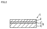
- FIG. 2 is a cross-sectional view schematically showing a cell structure included in the fuel cell of FIG.
- FIG. 3 is an SEM photograph of an example of a corrosion-resistant layer including a Ni—Sn layer.
- FIG. 4 is a graph showing a change with time in accordance with an increase in the number of operation of the voltage between the anode side separator and the cathode side separator of the fuel cell as a change in voltage decrease rate (deterioration rate).
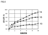
- FIG. 5 is a graph showing a change with time in accordance with an increase in the number of operation times of the voltage between the anode side separator and the cathode side separator of the fuel cell as a change in voltage decrease rate (deterioration rate).
- Electrons flowing to the cell are collected via a metallic material that contacts the anode and / or cathode. At this time, if there are few metal materials which contact an anode and / or a cathode, it will become difficult to flow an electron and resistance will become high.
- the expanded metal arranged for securing the gas flow path also plays a role as a current collector. However, since the expanded metal has a large hole diameter, the internal resistance during operation tends to be high.
- the present disclosure has been made in view of the above circumstances, and an object thereof is to provide a fuel cell with reduced internal resistance during operation.
- the present inventors first considered a configuration in which a material having a main role of current collection and a material having a main role of gas diffusibility are separately arranged.
- a metal material (current collector) having a current collecting function as a main role is arranged between the cell and the interconnector.
- an SOFC operating at a high temperature of 700 ° C. to 1000 ° C. is exposed to a wide temperature change from room temperature to 1000 ° C. when it is repeatedly operated and stopped. For this reason, a high thermal shock resistance is required for the current collector disposed between the cell and the interconnector. Further, the current collector is preferably a material having excellent corrosion resistance in a high temperature environment.
- the fuel cell of the present disclosure is: A cell structure including a cathode, an anode, and a solid electrolyte layer interposed between the cathode and the anode; A cathode separator facing the cathode, and an anode separator facing the anode, The cell structure is sandwiched between the cathode side separator and the anode side separator, Each of the cathode side separator and the anode side separator has a gas flow path, A current collector is provided between at least one of the anode side separator and the anode or between the cathode side separator and the cathode, The current collector is a metal mesh knitted with wire, The wire has a corrosion resistant layer.
- the current collector composed of the metal mesh has high heat resistance and thermal shock resistance. Moreover, since the corrosion-resistant layer is formed in the wire which comprises a metal mesh, the said electrical power collector also has high oxidation resistance. Therefore, according to the fuel cell, the internal resistance during operation of the fuel cell is reduced. In particular, in the case of a high fuel utilization rate, an increase in internal resistance during operation is more effectively suppressed.
- the corrosion resistant layer preferably contains Ni and Sn. Thereby, a corrosion-resistant layer can be further excellent in heat resistance. Sn easily forms an alloy with the metal constituting the metal mesh, and easily forms a corrosion-resistant layer. Especially, the alloy of Ni and Sn can have high heat resistance and high corrosion resistance (oxidation resistance).
- the corrosion-resistant layer includes a first phase and a second phase having different concentrations of Sn with respect to Ni, and the concentration of Sn in the first phase is higher than the concentration of Sn in the second phase.
- a corrosion-resistant layer can ensure corrosion resistance, heat resistance, and favorable electrical conductivity.
- the current collector can be provided between the anode separator and the anode.
- the current collector provided between the anode-side separator and the anode is appropriately referred to as “anode-side current collector”.
- anode-side current collector At the anode, a reaction of oxidizing a fuel such as hydrogen and releasing protons and electrons proceeds.
- the atmosphere around the anode and the anode-side current collector is basically a reducing atmosphere because it contains hydrogen gas.
- the amount of water (water vapor) increases on the anode side, and the atmosphere around the anode-side current collector tends to be oxidizing.
- the anode-side current collector when a porous nickel sintered body or a metal mesh made of only nickel is used as the anode-side current collector, nickel is easily oxidized during operation at a high temperature and a high fuel utilization rate. Internal resistance tends to increase. On the other hand, since the metal mesh has a corrosion resistant layer, the oxidation resistance is improved. For this reason, by using a metal mesh for the anode side current collector, the metal mesh is hardly oxidized even during operation at a high temperature and a high fuel utilization rate, thereby suppressing an increase in internal resistance.
- the solid electrolyte layer may have oxygen ion conductivity.
- protons and oxide ions react to produce water. Therefore, the atmosphere around the anode-side current collector tends to be an oxidizing atmosphere. According to the present disclosure, an increase in internal resistance can be suppressed even in this case.
- the operating temperature of the fuel cell may be 800 ° C. or higher.
- the atmosphere around the anode-side current collector tends to be a highly oxidizing atmosphere, but according to the present disclosure, an increase in internal resistance can be suppressed even in this case.
- the fuel utilization rate may be 75% or more.
- the atmosphere around the anode-side current collector tends to be a highly oxidizing atmosphere, but according to the present disclosure, an increase in internal resistance can be suppressed even in this case.
- the fuel utilization rate refers to the ratio of the amount of fuel actually used for cell reaction out of the amount of fuel supplied to the fuel cell via the fuel flow path.
- the fuel utilization rate can be calculated based on the amount of current flowing through the fuel cell and the flow rate of the fuel gas supplied via the fuel flow path.
- the current collector can be provided between the cathode separator and the cathode.
- the current collector provided between the cathode side separator and the cathode is appropriately referred to as a “cathode side current collector”.
- the oxidant (oxygen) introduced from the oxidant flow path is dissociated to generate oxide ions. For this reason, the periphery of the cathode and the cathode-side current collector is exposed to a high temperature and highly oxidizing atmosphere.
- the oxidation-resistant cathode-side current collector for example, lanthanum strontium cobalt ferrite (LSCF), which is also used as a cathode material, is used.
- LSCF lanthanum strontium cobalt ferrite
- the metal mesh has high heat resistance and thermal shock resistance, and has oxidation resistance by forming a corrosion-resistant layer on at least the surface layer of the metal mesh wire. For this reason, by using a metal mesh for the cathode current collector, it is possible to suppress an increase in internal resistance when the fuel cell is operated.
- the operating temperature of the fuel cell is preferably 700 ° C. or lower.
- a metal mesh provided with at least a corrosion-resistant layer as a cathode current collector.
- the SOFC using the above-described materials having proton conductivity such as BCY and BZY as the solid electrolyte layer operates in the middle temperature range of 400 ° C. to 600 ° C.
- the above metal mesh is preferably used as the cathode side current collector. be able to.
- the metal mesh is used as the cathode current collector.
- the cathode current collector can be preferably used.
- Metal mesh The metal mesh is formed by weaving a wire made of metal into a mesh, and the wire has a corrosion-resistant layer.
- a metal mesh may be processed into a mesh by braiding a wire in which a corrosion-resistant layer has been formed in advance, or after forming the wire into a mesh, a treatment for forming a corrosion-resistant layer on the mesh surface may be performed. .
- the formation of the corrosion resistant layer is preferably performed by plating.
- vapor deposition, chemical vapor deposition (CVD), plasma CVD, sputtering, or other vapor phase methods, or metal paste may be applied.
- the plating process, the vapor deposition process, and the sputtering process can be performed by a known method according to the material of the corrosion-resistant layer.
- any metal or alloy material such as Cu, Fe, Ni, Ag, Zn, brass, ferrochrome (an alloy of Fe and Cr), stainless steel (SUS), or the like can be used.
- the metal constituting the mesh is selected in consideration of the affinity with the corrosion resistant layer. Especially, it is preferable to employ Ni in terms of low resistivity, heat resistance, and cost for use as a current collector.
- the corrosion-resistant layer preferably contains Ni and Sn. This is because such a layer is excellent in both characteristics of corrosion resistance (oxidation resistance) and heat resistance. Especially, the alloy of Ni and Sn can have high corrosion resistance and high heat resistance. Therefore, an alloy layer of Ni and Sn (hereinafter referred to as “Ni—Sn layer” as appropriate) can be preferably employed as the corrosion resistant layer.
- an Ni—Sn layer is formed on the surface of the metal mesh by performing electrolytic plating using a plating solution containing stannous chloride, nickel chloride, and potassium pyrophosphate on the surface of the wire. be able to.
- the Ni—Sn layer can be formed, for example, by plating a wire made of Ni with a Sn layer or a layer made of an alloy of Ni and Sn. That is, the surface of the Ni wire is coated with a Sn layer or a layer made of an alloy of Ni and Sn using a plating process or the like, and then heat-treated in a reducing atmosphere. As a result, Sn diffuses inside the wire, and the Ni—Sn layer can be changed from the surface layer of the wire to a region having a certain depth.
- an Sn plating layer is formed on the underlying Ni wire by an electrolytic plating process using a plating solution containing sulfuric acid and stannous sulfate. To do. Thereafter, Sn can be diffused into the Ni wire by heat treatment in a reducing atmosphere at 800 to 1000 ° C. From the viewpoint of easily forming the Ni—Sn alloy layer, it is preferable to employ Ni as the wire.
- the corrosion-resistant layer includes a first phase and a second phase having different concentrations of Sn with respect to Ni, and the concentration of Sn in the first phase is higher than the concentration of Sn in the second phase.
- a configuration is easy when the corrosion-resistant layer is the above-described Ni—Si layer. According to this corrosion-resistant layer, corrosion resistance, corrosion resistance, heat resistance and good electrical conductivity can be ensured. The reason is as follows.
- Ni and Sn are present in the form of an intermetallic compound (for example, Ni 3 Sn).
- the second phase is a phase containing Ni as a main component, and it is considered that Sn is present in the form of a solid solution in Ni.
- the first phase that is the intermetallic compound phase has higher corrosion resistance than the second phase.
- the second phase has higher heat resistance and electrical conductivity than the first phase. For this reason, the corrosion-resistant layer having the first phase and the second phase can have corrosion resistance, heat resistance, and good electrical conductivity.
- the composition ratio of Ni and Sn is set so that the ratio of Sn contained in the Ni—Sn layer is 100% by mass based on the total amount of Ni and Sn.
- the content is preferably 4% by mass or more, and more preferably 5% by mass or more.
- the higher the proportion of the first phase the relatively lower the proportion of the second phase, so there is a concern about the decrease in heat resistance and electrical conductivity.
- the ratio of Sn contained in the Ni—Sn layer is 15% by mass or less with the total amount of Ni and Sn contained in the Ni—Sn layer being 100% by mass. It is preferable that it is 10% by mass or less.
- the Ni—Sn layer has an intermetallic compound phase (first phase) containing Ni 3 Sn as a main component and Ni as the main component. And two phases of the phase in which Sn is dissolved in Ni (second phase) are observed at an appropriate ratio. In this case, higher corrosion resistance, higher heat resistance, and better electrical conductivity can be ensured.
- FIG. 3 shows an SEM photograph of the cross section of the Ni—Sn layer.
- FIG. 3 is a cross-sectional photograph of a porous metal body (Celmet) on which a Ni—Sn layer is formed.
- This Ni—Si layer is composed of the first phase and the second phase described above.
- the metal mesh having the Ni—Si alloy layer also shows the same composition distribution as in FIG. 3 at least in the surface layer.
- the Ni—Sn layer has two phases, a portion indicated as Location 1 (first phase) and a darker gray portion (second phase) that is blacker than Location 1 and indicated as Location 2.
- first phase a portion indicated as Location 1
- second phase a darker gray portion
- Sn sulfur
- O oxygen
- Ni, Sn, and O were contained in atomic fractions of 91 at%, 4 at%, and 5 at%, respectively. From this, it is considered that Sn is contained in a state of being dissolved in Ni in Location 2.
- all of the wires constituting the metal mesh are Ni—Sn layers. That is, the wire itself is more preferably an alloy of Ni and Sn. In this case, not only the surface of the wire but also the wire itself can have the various characteristics described above.
- a metal mesh in which Co or Mn is coated as an anticorrosion layer on an Fe—Cr alloy may be used.
- the mesh size (opening) of the metal mesh is, for example, a square with sides of 0.5 mm to 1 mm.
- the metal mesh on which the above corrosion-resistant layer is formed is used for an anode-side current collector or a cathode-side current collector of a solid oxide fuel cell (SOFC).
- SOFC solid oxide fuel cell
- FIG. 1 schematically shows the configuration of a fuel cell (solid oxide fuel cell) according to an embodiment.
- the fuel cell 10 includes a cell structure 1.
- An example of a schematic cross-sectional view of the cell structure is shown in FIG.
- the cell structure 1 includes a cathode 2, an anode 3, and a solid electrolyte layer 4 interposed therebetween.
- the anode 3 and the solid electrolyte layer 4 are integrated to form an electrolyte layer-electrode assembly 5.
- the fuel cell 10 includes an oxidant channel 23 for supplying an oxidant to the cathode, a fuel channel 53 for supplying fuel to the anode, and a cathode, as shown in FIG.
- the side separator 22 and the anode side separator 52 are provided.
- the oxidant flow path 23 is formed by the cathode side separator 22, and the fuel flow path 53 is formed by the anode side separator 52. That is, the oxidant channel 23 is a gas channel that the cathode-side separator 22 has, and the fuel channel 53 is a gas channel that the anode-side separator 52 has.
- the cell structure 1 is sandwiched between the cathode side separator 22 and the anode side separator 52.
- the oxidant flow path 23 of the cathode side separator 22 is disposed to face the cathode 2 of the cell structure 1, and the fuel flow path 53 of the anode side separator 52 is disposed to face the anode 3.
- the individual components of the fuel battery cell will be further described.
- Solid electrolyte layer As the solid electrolyte layer, a layer having proton conductivity or oxygen ion conductivity in a predetermined temperature range is used. A known material can be used for the solid electrolyte layer. Examples of the metal oxide having oxygen ion conductivity include yttrium-stabilized zirconia (YSZ). In this case, the SOFC using YSZ as the electrolyte must be operated at a high temperature of 750 ° C. to 1000 ° C.
- YSZ yttrium-stabilized zirconia
- the metal oxide having proton conductivity examples include perovskite oxides such as BaCe 0.8 Y 0.2 O 2.9 (BCY) and BaZr 0.8 Y 0.2 O 2.9 (BZY). Is mentioned. Since BCY and BZY exhibit high proton conductivity in the middle temperature range of 400 ° C. to 600 ° C., BCY and BZY can be used as a solid electrolyte layer of a medium temperature fuel cell. These metal oxides can be formed, for example, by sintering and used as a solid electrolyte layer.
- BCY and BZY can be used as a solid electrolyte layer of a medium temperature fuel cell.
- the solid electrolyte layer 4 moves protons generated at the anode 3 to the cathode 2.
- the solid electrolyte layer 4 moves oxide ions generated at the cathode 2 to the anode 3.
- the thickness of the solid electrolyte layer is, for example, 1 ⁇ m to 50 ⁇ m, preferably 3 ⁇ m to 20 ⁇ m. When the thickness of the solid electrolyte layer is in such a range, it is preferable in that the resistance of the solid electrolyte layer can be kept low.
- the solid electrolyte layer forms a cell structure together with the cathode and the anode and can be incorporated into the fuel cell.
- the solid electrolyte layer is sandwiched between the cathode and the anode, and one main surface of the solid electrolyte layer is in contact with the anode, and the other main surface is in contact with the cathode.
- the cathode has a porous structure.
- a reaction oxygen reduction reaction
- oxide ions are generated when the oxidant (oxygen) introduced from the oxidant flow path is dissociated.
- a known material can be used as the cathode material.
- the cathode material for example, a compound containing lanthanum and having a perovskite structure (ferrite, manganite, and / or cobaltite, etc.) is preferable, and among these compounds, a compound further containing strontium is more preferable.
- the cathode may contain a catalyst such as Pt. When a catalyst is included, the cathode can be formed by mixing the catalyst and the above materials and sintering.
- the cathode can be formed, for example, by sintering raw materials of the above materials. If necessary, a binder, an additive, and / or a dispersion medium may be used together with the raw material.
- the thickness of the cathode is not particularly limited, but can be appropriately determined from 5 ⁇ m to 2 mm, for example, and may be about 5 ⁇ m to 40 ⁇ m.
- the anode has a porous structure.
- a reaction oxidation reaction of fuel
- fuel such as hydrogen introduced from the fuel flow path and releases protons and electrons
- an oxygen ion conductive solid electrolyte layer is used, a reaction (oxygen reduction reaction) between oxide ions and protons conducted through the solid electrolyte layer proceeds at the anode.
- a known material can be used as the material for the anode.
- a proton conductive solid electrolyte layer nickel oxide (NiO) as a catalyst component and proton conductors (yttrium oxide (Y 2 O 3 ), BCY, BZY constituting the solid electrolyte layer) Etc.) and the like.
- NiO nickel oxide
- Y 2 O 3 yttrium oxide
- BCY BCY
- Etc. yttrium oxide
- an oxygen ion conductive solid electrolyte layer a composite oxide of nickel oxide (NiO) that is a catalyst and an electronic conductor component and an oxygen ion conductor (YSZ or the like) that constitutes the solid electrolyte layer can be used. .
- the anode can be formed, for example, by sintering raw materials.
- the anode can be formed by sintering a mixture of NiO powder and proton conductor powder.
- the thickness of the anode can be appropriately determined from 10 ⁇ m to 2 mm, for example, and may be 100 ⁇ m to 600 ⁇ m.
- the thickness of the anode 3 is larger than that of the cathode 2, and the anode 3 functions as a support for supporting the solid electrolyte layer 4 (and thus the cell structure 1).
- the thickness of the anode 3 is not necessarily larger than that of the cathode 2.
- the thickness of the anode 3 may be approximately the same as the thickness of the cathode 2.
- the anode and the solid electrolyte layer are integrated.
- the present invention is not limited to this, and the cathode and the solid electrolyte layer are integrated to form an electrolyte layer-electrode assembly. May be.
- the oxidant flow path 23 has an oxidant inlet into which the oxidant flows and an oxidant discharge port through which water generated by the reaction, unused oxidant, and the like are discharged (both not shown).
- the oxidizing agent include a gas containing oxygen.
- the fuel flow path 53 has a fuel gas inlet through which fuel gas flows, and a fuel gas outlet through which unused fuel, H 2 O, N 2 , CO 2 and the like generated by the reaction are discharged (all not shown). ).
- the fuel gas include gas containing gas such as hydrogen, methane, ammonia, carbon monoxide.
- the fuel cell 10 includes a cathode-side current collector 21 disposed between the cathode 2 and the cathode-side separator 22, and an anode-side current collector 51 disposed between the anode 3 and the anode-side separator 52. You may prepare.
- the cathode-side current collector 21 functions to diffuse and supply the oxidant gas introduced from the oxidant flow path 23 to the cathode 2.
- the anode current collector 51 functions to diffuse and supply the fuel gas introduced from the fuel flow path 53 to the anode 3. Therefore, each current collector is preferably a structure having sufficient air permeability.
- the metal mesh having the above-mentioned corrosion-resistant layer can be used as the anode-side current collector 51.
- the metal mesh has sufficient heat resistance and oxidation resistance even when the operating temperature is 800 ° C. or higher, particularly when exposed to a high-temperature oxidizing atmosphere in which the fuel utilization rate is 75% or higher. .
- the upper limit value of the operating temperature is not particularly limited, but can be set to 920 ° C. from the viewpoint of the stability of the first phase that is the intermetallic compound phase.
- the upper limit value of the fuel utilization rate is theoretically 100%.
- the anode-side current collector 51 may be, for example, silver, silver alloy, nickel, nickel alloy in addition to the metal mesh It is also possible to use a metal porous body containing a metal, a metal mesh (without a corrosion-resistant layer), a punching metal, an expanded metal, or the like. Especially, a metal porous body is preferable at the point of lightweight property or air permeability. In particular, a porous metal body having a three-dimensional network structure is preferable.
- the three-dimensional network structure refers to a structure in which rod-like or fibrous metals constituting a metal porous body are three-dimensionally connected to form a network. For example, a sponge-like structure or a nonwoven fabric-like structure can be mentioned.
- the metal porous body can be formed, for example, by coating a resin porous body having continuous voids with the metal as described above. When the internal resin is removed after the metal coating process, a cavity is formed inside the skeleton of the metal porous body, and the metal becomes hollow.
- nickel “Celmet” manufactured by Sumitomo Electric Industries, Ltd. can be used as a commercially available metal porous body having such a structure.
- the cathode-side current collector 21 is exposed to an oxidizing atmosphere higher than that of the anode side, a material having higher oxidation resistance than the anode-side current collector 51 is desired.
- a material obtained by processing LSCF which is a material constituting the cathode, into a paste form can be used.
- the metal mesh having the above-mentioned corrosion resistant layer is preferably used as the cathode current collector 21.
- a metal mesh having a corrosion-resistant layer has higher thermal shock resistance than LSCF.
- the lower limit of the operating temperature is not particularly limited, but can be 300 ° C. from the viewpoint of the activity of the catalyst.
- the lower limit value of the fuel utilization rate is not particularly limited, but can be 10% from the viewpoint of appropriate utilization.
- a fuel cell When a fuel cell is configured by stacking a plurality of cell structures, for example, the cell structure 1, the cathode side separator 22, and the anode side separator 52 are stacked as a unit.
- the plurality of cell structures 1 may be connected in series by, for example, a separator having gas channels (oxidant channels and fuel channels) on both surfaces.
- the material of the separator examples include heat-resistant alloys such as stainless steel, nickel-base alloy, and chromium-base alloy. Of these, stainless steel is preferable because it is inexpensive. In a proton conductive solid oxide fuel cell (PCFC), since the operating temperature is about 400 ° C. to 600 ° C., stainless steel can be used as a separator material. In the case of an SOFC that operates at a high temperature of about 800 ° C. or more, such as when an oxygen ion conductive solid electrolyte is used, a nickel-based alloy, a chromium-based alloy, or the like is used as a separator material.
- PCFC proton conductive solid oxide fuel cell
- the fuel cell can be manufactured by a known method except that the above cell structure is used.
- Appendix 1 A cell structure including a cathode, an anode, and a solid electrolyte layer interposed between the cathode and the anode; An oxidant flow path for supplying an oxidant to the cathode, A fuel flow path for supplying fuel to the anode, An anode separator, and A cathode side separator, A current collector is provided between the anode separator and the anode, or at least one of the cathode separator and the cathode, The current collector is a metal mesh in which a wire is knitted, and includes a corrosion-resistant layer on at least a surface layer of the wire.
- Example 1 A fuel cell using YSZ as a solid electrolyte layer was prepared and evaluated as follows.
- metal mesh Ni mesh made by Taiyo Wire Mesh, mesh opening 0.5 mm
- a plating solution containing stannous sulfate, sulfuric acid, cresolsulfonic acid, gelatin, and ⁇ -naphthol
- electrolytic plating treatment is performed. went. Thereafter, heat treatment was performed in a hydrogen atmosphere at 1000 ° C. for 2 hours.
- a metal mesh (Ni—Sn mesh) X1 provided with a Ni—Sn layer was obtained.
- NiO was mixed with YSZ powder, which is a solid solution of ZrO 2 and Y 2 O 3 , so as to contain 70% by volume of NiO (catalyst raw material), and pulverized and kneaded by a ball mill.
- the ratio (atomic composition ratio) between Zr and Y in YSZ was 90:10.
- a slurry containing the obtained mixture (55% by volume) and a binder (PVB resin, 45% by volume) was processed into a 1.0 mm thick sheet by a doctor blade method to obtain an anode precursor sheet. .
- a slurry containing the YSZ powder (55% by volume) and the binder (PVB resin, 45% by volume) is processed into a sheet having a thickness of 12 ⁇ m by a doctor blade method, and a precursor sheet for a solid electrolyte layer Got.
- LSCF La 0.6 Sr 0.4 Co 0.2 Fe 0.8 O 3- ⁇
- organic solvent butyl carbitol acetate
- the operating temperature was 900 ° C.
- hydrogen was supplied as a fuel gas to the anode of the produced fuel cell at 0.3 L / min
- air was supplied to the cathode at 1.0 L / min.
- Each lead wire was connected to an electronic load device, and the current and voltage flowing between the anode side separator and the cathode side separator were measured.
- the electronic load device was set so that the current flowing between the anode side separator and the cathode side separator would be 32 A so that the fuel utilization rate would be 75%.
- V1 E ⁇ rI, where E is the electromotive force generated in the fuel cell, r is the internal resistance generated in the current collector, and I is the current between the anode side separator and the cathode side separator. Can do. Therefore, when the current I is constant, the voltage V1 decreases and the deterioration rate A increases as the internal resistance r increases.
- Example 1 A fuel cell using an Ni metal mesh X2 in which a corrosion-resistant layer was not formed as an anode current collector was produced in the same manner as in Example 1 to obtain a fuel cell Y2. The deterioration rate of the fuel cell Y2 was evaluated in the same manner as in Example 1.
- Example 2 Fabrication of fuel cell
- a Ni metal mesh on which no corrosion-resistant layer is formed is laminated as an anode current collector on the surface of the anode of the cell structure.
- a stainless steel anode-side separator was laminated.
- a metal mesh X1 having a corrosion-resistant layer was laminated as a cathode current collector on the surface of the cathode, and a stainless steel cathode side separator having a gas flow path was further laminated. Except for this, a fuel cell Y3 was obtained in the same manner as the fuel cell Y1 of Example 1.
- Example 2 A fuel cell using a Ni metal mesh X2 on which no corrosion-resistant layer was formed as a cathode current collector was produced in the same manner as in Example 2 to obtain a fuel cell Y4. The deterioration rate of the fuel cell Y4 was evaluated in the same manner as in Example 2.
- the fuel cell Y5 by increasing the thickness of the cathode, a part of the cathode material located on the cathode side separator functions as a cathode current collector.
- the thickness of the fired cathode was 50 ⁇ m.
- the LSCF layer having a thickness of 40 ⁇ m on the side in contact with the cathode side separator corresponds to the cathode current collector.
- the deterioration rate of the fuel cell Y5 was evaluated in the same manner as in Example 2.
- the internal resistance increases greatly as the cumulative operation time becomes longer. This is because the operating temperature of the fuel cell is high (900 ° C.), and the fuel cell is operated at a high fuel utilization rate, so the area around the anode and the anode current collector is locally in an oxidizing atmosphere, This is probably because the surface of the Ni mesh used as the anode current collector was oxidized and the resistance increased.
- the fuel cell Y1 an increase in internal resistance is suppressed even during a long cumulative operation. This is probably because the Ni—Sn mesh provided with the corrosion-resistant layer is used, so that the corrosion resistance and oxidation resistance are high, and the current collector is suppressed from being oxidized.
- the fuel cells Y1 and Y2 after the evaluation were disassembled, the anode current collector was taken out, and the surface was observed.
- the Ni metal mesh X2 was oxidized to form nickel oxide.
- oxidation of nickel in the mesh X1 was not observed.
- the internal resistance increases greatly as the cumulative operation time becomes longer. This is probably because the fuel cell Y4 has an oxidizing atmosphere around the cathode and the cathode current collector, so that the surface of the Ni mesh used as the cathode current collector was oxidized and the resistance increased. Regarding the fuel cell Y5, it is considered that a part of the LSCF functioning as the cathode current collector was broken and dropped due to thermal shock as the operation and the stop were repeated.
- the metal mesh has a thermal shock resistance and is a Ni—Sn mesh provided with a corrosion resistant layer, so that the corrosion resistant layer suppresses oxidation of Ni.
- the surface of the Ni metal mesh X2 was oxidized to form nickel oxide.
- oxidation of nickel in the metal mesh X1 was not observed.
- the fuel cell according to the present embodiment is suitable for use in SOFC and can realize SOFC with low internal resistance during operation.
Abstract
This fuel cell is provided with: a cell structure that includes a cathode, an anode, and a solid electrolyte layer provided between the cathode and the anode; a cathode-side separator that is opposed to the cathode; and an anode-side separator that is opposed to the anode, wherein the cell structure is held between the cathode-side separator and the anode-side separator, the cathode-side separator and the anode-side separator each have gas flow paths, a collector is provided between the anode-side separator and the anode and/or between the cathode-side separator and the cathode, the collector is a metal mesh formed from woven wire, and the wire has a corrosion resistant layer.
Description
本開示は、燃料電池に関する。本出願は、2018年2月27日に出願した日本特許出願である特願2018-032913号に基づく優先権を主張する。当該日本特許出願に記載された全ての記載内容は、参照によって本明細書に援用される。
This disclosure relates to fuel cells. This application claims priority based on Japanese Patent Application No. 2018-032913, which is a Japanese patent application filed on February 27, 2018. All the descriptions described in the Japanese patent application are incorporated herein by reference.
燃料電池は、水素などの燃料ガスと空気(酸素)との電気化学反応によって発電する装置であり、化学エネルギーを電気に直接変換できるため、発電効率が高い。なかでも、作動温度が700℃以上、特には800℃~1000℃程度である固体酸化物型燃料電池(以下、SOFCと称する)は、反応速度が速いため、有望視されている。SOFCには、固体酸化物を含む電解質層が、セラミックス(焼結体)により形成される2枚の電極で挟まれて一体化されたMEA(Membrane Electrode Assembly、膜-電極接合体)が使用される。MEAの構成要素はすべて固体であるため、取り扱いが容易である。
A fuel cell is a device that generates electricity by an electrochemical reaction between a fuel gas such as hydrogen and air (oxygen), and has high power generation efficiency because it can directly convert chemical energy into electricity. Among them, a solid oxide fuel cell (hereinafter referred to as SOFC) having an operating temperature of 700 ° C. or higher, particularly about 800 ° C. to 1000 ° C. is considered promising because of its high reaction rate. SOFC uses MEA (Membrane Electrode Assembly, membrane-electrode assembly) in which an electrolyte layer containing a solid oxide is sandwiched between two electrodes formed of ceramics (sintered body). The All components of the MEA are solid and easy to handle.
固体電解質として、酸素イオン伝導性を有する金属酸化物、例えばイットリウム安定化ジルコニア(YSZ:Yttria-Stabilized Zirconia)が使用されている。酸素イオン伝導性のYSZを電解質として使用するSOFCの作動温度は、750℃~1000℃の高温である。加熱に必要なエネルギー消費の低減や、耐高温性を有する材料の選択性の観点から、安価な汎用ステンレス鋼を利用できる400℃~600℃の中温域で作動するSOFCの開発が進められている。BaCe0.8Y0.2O2.9(BCY)、BaZr0.8Y0.2O2.9(BZY)などのペロブスカイト酸化物は、中温域で高いプロトン伝導性を示すため、中温型燃料電池の固体電解質として期待されている。
As the solid electrolyte, a metal oxide having oxygen ion conductivity, such as yttrium-stabilized zirconia (YSZ) is used. The operating temperature of SOFC using oxygen ion conductive YSZ as an electrolyte is a high temperature of 750 ° C. to 1000 ° C. From the viewpoint of reducing the energy consumption required for heating and the selectivity of materials having high temperature resistance, development of SOFCs operating in the middle temperature range of 400 ° C to 600 ° C that can use inexpensive general-purpose stainless steel is underway. . Perovskite oxides such as BaCe 0.8 Y 0.2 O 2.9 (BCY) and BaZr 0.8 Y 0.2 O 2.9 (BZY) exhibit high proton conductivity in the middle temperature range. It is expected as a solid electrolyte for type fuel cells.
燃料電池においては、通常、大きな電力を得るために、複数のMEAが積層されて配置され、MEA同士の間には、燃料ガスと空気とを分離するインターコネクタ(セパレータ)が配置される。インターコネクタは、発生した電流を外部へ取り出すための集電機能も有する。
In a fuel cell, in order to obtain large electric power, a plurality of MEAs are usually stacked and an interconnector (separator) that separates fuel gas and air is disposed between the MEAs. The interconnector also has a current collecting function for taking out the generated current to the outside.
燃料電池には、MEAに燃料ガスあるいは空気を供給するため、MEAに隣接するガス流路が必要とされる。ガス流路を確保するために、例えば特許文献1(特開2007-250297号公報)では、MEAとインターコネクタとの間にエキスパンドメタルが配置されている。特許文献2(国際公開第2003/12903号パンフレット)は、インターコネクタに、エッチング等によりガス流路となるディンプルを形成する方法を教示している。
A fuel cell requires a gas flow path adjacent to the MEA in order to supply fuel gas or air to the MEA. In order to secure the gas flow path, for example, in Patent Document 1 (Japanese Patent Laid-Open No. 2007-250297), an expanded metal is disposed between the MEA and the interconnector. Patent Document 2 (International Publication No. 2003/12903 pamphlet) teaches a method of forming dimples serving as gas flow paths in an interconnector by etching or the like.
本開示に係る燃料電池は、カソードと、アノードと、前記カソード及び前記アノードの間に介在する固体電解質層とを含むセル構造体、前記カソードに対向するカソード側セパレータ、および前記アノードに対向するアノード側セパレータ、を備え、前記セル構造体は、前記カソード側セパレータおよび前記アノード側セパレータに挟持され、前記カソード側セパレータおよび前記アノード側セパレータは、ガス流路を有し、前記アノード側セパレータと前記アノードの間、または、前記カソード側セパレータと前記カソードの間の少なくともいずれか一方に、集電体が設けられ、前記集電体は線材が編み込まれた金属メッシュであり、前記線材は耐腐食層を有する。
A fuel cell according to the present disclosure includes a cell structure including a cathode, an anode, and a solid electrolyte layer interposed between the cathode and the anode, a cathode-side separator facing the cathode, and an anode facing the anode A side separator, wherein the cell structure is sandwiched between the cathode side separator and the anode side separator, the cathode side separator and the anode side separator have gas flow paths, and the anode side separator and the anode Or at least one of the cathode side separator and the cathode is provided with a current collector, and the current collector is a metal mesh knitted with a wire, and the wire has a corrosion-resistant layer. Have.
[本開示が解決しようとする課題]
セルに流れる電子は、アノードおよび/またはカソードに接触する金属材料を経由して集電される。このとき、アノードおよび/またはカソードと接触する金属材料が少ないと、電子が流れにくくなって、抵抗が高くなる。特許文献1の方法では、ガス流路の確保のために配置されるエキスパンドメタルが、集電体としての役割も担う。しかし、エキスパンドメタルは孔径が大きいため、作動時における内部抵抗が高くなり易い。 [Problems to be solved by this disclosure]
Electrons flowing to the cell are collected via a metallic material that contacts the anode and / or cathode. At this time, if there are few metal materials which contact an anode and / or a cathode, it will become difficult to flow an electron and resistance will become high. In the method ofPatent Document 1, the expanded metal arranged for securing the gas flow path also plays a role as a current collector. However, since the expanded metal has a large hole diameter, the internal resistance during operation tends to be high.
セルに流れる電子は、アノードおよび/またはカソードに接触する金属材料を経由して集電される。このとき、アノードおよび/またはカソードと接触する金属材料が少ないと、電子が流れにくくなって、抵抗が高くなる。特許文献1の方法では、ガス流路の確保のために配置されるエキスパンドメタルが、集電体としての役割も担う。しかし、エキスパンドメタルは孔径が大きいため、作動時における内部抵抗が高くなり易い。 [Problems to be solved by this disclosure]
Electrons flowing to the cell are collected via a metallic material that contacts the anode and / or cathode. At this time, if there are few metal materials which contact an anode and / or a cathode, it will become difficult to flow an electron and resistance will become high. In the method of
本開示は上記事情に鑑みてなされたものであり、作動時の内部抵抗が低減された燃料電池を提供することを目的とする。
The present disclosure has been made in view of the above circumstances, and an object thereof is to provide a fuel cell with reduced internal resistance during operation.
[本開示の効果]
本開示によれば、燃料電池の作動時の内部抵抗を低減することができる。 [Effects of the present disclosure]
According to this indication, internal resistance at the time of operation of a fuel cell can be reduced.
本開示によれば、燃料電池の作動時の内部抵抗を低減することができる。 [Effects of the present disclosure]
According to this indication, internal resistance at the time of operation of a fuel cell can be reduced.
[実施形態の説明]
本発明者らはまず、内部抵抗の低減を図るべく、集電性を主な役割とする材料と、ガス拡散性を主な役割とする材料とを、それぞれ別に配置する構成を考えた。例えば、セルとインターコネクタとの間に、集電機能を主な役割とする金属材料(集電体)を配置する構成である。 [Description of Embodiment]
In order to reduce internal resistance, the present inventors first considered a configuration in which a material having a main role of current collection and a material having a main role of gas diffusibility are separately arranged. For example, a metal material (current collector) having a current collecting function as a main role is arranged between the cell and the interconnector.
一方、700℃~1000℃の高温で作動するSOFCは、稼動と停止を繰り返すと、室温から1000℃までの広範な温度変化にさらされる。このため、セルとインターコネクタの間に配置される集電体には、高い耐熱衝撃性が必要とされる。また、集電体は、高温環境における耐腐食性に優れた材料が好ましい。
On the other hand, an SOFC operating at a high temperature of 700 ° C. to 1000 ° C. is exposed to a wide temperature change from room temperature to 1000 ° C. when it is repeatedly operated and stopped. For this reason, a high thermal shock resistance is required for the current collector disposed between the cell and the interconnector. Further, the current collector is preferably a material having excellent corrosion resistance in a high temperature environment.
以上を踏まえて鋭意検討を重ねて、本開示の燃料電池を完成させた。以下に、本開示の実施形態の内容を列記して説明する。
Based on the above, earnest studies were repeated and the fuel cell of the present disclosure was completed. The contents of the embodiments of the present disclosure will be listed and described below.
(1)本開示の燃料電池は、
カソードと、アノードと、カソード及びアノードの間に介在する固体電解質層とを含むセル構造体、
カソードに対向するカソード側セパレータ、および
アノードに対向するアノード側セパレータ、を備え、
セル構造体は、カソード側セパレータおよびアノード側セパレータに挟持され、
カソード側セパレータおよびアノード側セパレータは、それぞれガス流路を有し、
アノード側セパレータとアノードの間、または、カソード側セパレータとカソードの間の少なくともいずれか一方に、集電体が設けられ、
集電体は線材が編み込まれた金属メッシュであり、
前記線材は耐腐食層を有する。 (1) The fuel cell of the present disclosure is:
A cell structure including a cathode, an anode, and a solid electrolyte layer interposed between the cathode and the anode;
A cathode separator facing the cathode, and an anode separator facing the anode,
The cell structure is sandwiched between the cathode side separator and the anode side separator,
Each of the cathode side separator and the anode side separator has a gas flow path,
A current collector is provided between at least one of the anode side separator and the anode or between the cathode side separator and the cathode,
The current collector is a metal mesh knitted with wire,
The wire has a corrosion resistant layer.
上記金属メッシュで構成された集電体は、高い耐熱性と耐熱衝撃性とを有している。また、金属メッシュを構成する線材には耐腐食層が形成されているため、上記集電体は高い耐酸化性をも有している。したがって上記燃料電池によれば、燃料電池の作動時の内部抵抗が低減される。特に、高燃料利用率の場合に、稼動時の内部抵抗の上昇がより効果的に抑制される。
The current collector composed of the metal mesh has high heat resistance and thermal shock resistance. Moreover, since the corrosion-resistant layer is formed in the wire which comprises a metal mesh, the said electrical power collector also has high oxidation resistance. Therefore, according to the fuel cell, the internal resistance during operation of the fuel cell is reduced. In particular, in the case of a high fuel utilization rate, an increase in internal resistance during operation is more effectively suppressed.
(2)上記耐腐食層は、NiおよびSnを含むことが好ましい。これにより、耐腐食層はさらに耐熱性に優れることができる。Snは、金属メッシュを構成する金属と合金を形成し易く、耐腐食層を形成し易い。なかでも、NiとSnとの合金は、高い耐熱性および高い耐腐食性(耐酸化性)を有することができる。
(2) The corrosion resistant layer preferably contains Ni and Sn. Thereby, a corrosion-resistant layer can be further excellent in heat resistance. Sn easily forms an alloy with the metal constituting the metal mesh, and easily forms a corrosion-resistant layer. Especially, the alloy of Ni and Sn can have high heat resistance and high corrosion resistance (oxidation resistance).
(3)上記耐腐食層は、Niに対するSnの濃度が異なる第1相と第2相とを含み、第1相のSnの濃度が第2相のSnの濃度よりも高いことが好ましい。これにより、耐腐食層は、耐腐食性、耐熱性および良好な電気伝導性を確保できる。
(3) It is preferable that the corrosion-resistant layer includes a first phase and a second phase having different concentrations of Sn with respect to Ni, and the concentration of Sn in the first phase is higher than the concentration of Sn in the second phase. Thereby, a corrosion-resistant layer can ensure corrosion resistance, heat resistance, and favorable electrical conductivity.
(4)上記燃料電池において、集電体は、アノード側セパレータとアノードの間に設けられることができる。以下において、アノード側セパレータとアノードの間に設けられた集電体を、適宜「アノード側集電体」と称する。アノードでは、水素などの燃料を酸化して、プロトンと電子とを放出する反応が進行する。アノードおよびアノード側集電体周辺の雰囲気は、水素ガスが含まれていることから、基本的に還元性の雰囲気である。しかしながら、高温で、且つ高い燃料利用率で稼動させる場合には、アノード側で水(水蒸気)の量が多くなり、アノード側集電体の周辺の雰囲気が酸化性に傾く。
(4) In the fuel cell, the current collector can be provided between the anode separator and the anode. Hereinafter, the current collector provided between the anode-side separator and the anode is appropriately referred to as “anode-side current collector”. At the anode, a reaction of oxidizing a fuel such as hydrogen and releasing protons and electrons proceeds. The atmosphere around the anode and the anode-side current collector is basically a reducing atmosphere because it contains hydrogen gas. However, when operating at a high temperature and a high fuel utilization rate, the amount of water (water vapor) increases on the anode side, and the atmosphere around the anode-side current collector tends to be oxidizing.
アノード側集電体として、例えば多孔質のニッケル焼結体や、ニッケルのみからなる金属メッシュを用いる場合には、高温且つ高い燃料利用率での稼動において、ニッケルが酸化され易く、これに伴って内部抵抗が上昇し易い。これに対し、上記金属メッシュは耐腐食層を有するため、耐酸化性が向上している。このため金属メッシュをアノード側集電体に用いることで、高温且つ高い燃料利用率での稼動においても金属メッシュが酸化され難く、もって内部抵抗の上昇を抑制できる。
For example, when a porous nickel sintered body or a metal mesh made of only nickel is used as the anode-side current collector, nickel is easily oxidized during operation at a high temperature and a high fuel utilization rate. Internal resistance tends to increase. On the other hand, since the metal mesh has a corrosion resistant layer, the oxidation resistance is improved. For this reason, by using a metal mesh for the anode side current collector, the metal mesh is hardly oxidized even during operation at a high temperature and a high fuel utilization rate, thereby suppressing an increase in internal resistance.
(5)(4)において、固体電解質層が、酸素イオン伝導性を有してもよい。この場合、アノード側において、プロトンと酸化物イオンが反応して水が生成する。したがって、アノード側集電体の周辺の雰囲気が酸化性雰囲気となり易い。本開示によれば、この場合においても内部抵抗の上昇を抑制できる。
(5) In (4), the solid electrolyte layer may have oxygen ion conductivity. In this case, on the anode side, protons and oxide ions react to produce water. Therefore, the atmosphere around the anode-side current collector tends to be an oxidizing atmosphere. According to the present disclosure, an increase in internal resistance can be suppressed even in this case.
(6)(4)において、燃料電池の作動温度が800℃以上であってもよい。このような高温では、アノード側集電体の周辺の雰囲気が高い酸化性雰囲気となり易いが、本開示によれば、この場合においても内部抵抗の上昇を抑制できる。
(6) In (4), the operating temperature of the fuel cell may be 800 ° C. or higher. At such a high temperature, the atmosphere around the anode-side current collector tends to be a highly oxidizing atmosphere, but according to the present disclosure, an increase in internal resistance can be suppressed even in this case.
(7)(4)において、燃料利用率が75%以上であってもよい。このような高い燃料利用率では、アノード側集電体の周辺の雰囲気が高い酸化性雰囲気となり易いが、本開示によれば、この場合においても内部抵抗の上昇を抑制できる。
(7) In (4), the fuel utilization rate may be 75% or more. With such a high fuel utilization rate, the atmosphere around the anode-side current collector tends to be a highly oxidizing atmosphere, but according to the present disclosure, an increase in internal resistance can be suppressed even in this case.
なお、燃料利用率とは、燃料流路を介して燃料電池に供給した燃料量のうち、実際に電池反応に使用された燃料量の割合を指す。燃料利用率は、燃料電池により流れた電流量、および、燃料流路を介して供給された燃料ガスの流量に基づいて算出できる。
The fuel utilization rate refers to the ratio of the amount of fuel actually used for cell reaction out of the amount of fuel supplied to the fuel cell via the fuel flow path. The fuel utilization rate can be calculated based on the amount of current flowing through the fuel cell and the flow rate of the fuel gas supplied via the fuel flow path.
(8)上記燃料電池において、集電体は、カソード側セパレータとカソードの間に設けられることができる。以下において、カソード側セパレータとカソードの間に設けられた集電体を、適宜「カソード側集電体」と称する。カソードでは、酸化剤流路から導入された酸化剤(酸素)が解離し、酸化物イオンが生成される。このため、カソードおよびカソード側集電体の周辺は、高温であり、且つ高酸化性の雰囲気にさらされている。
(8) In the fuel cell, the current collector can be provided between the cathode separator and the cathode. Hereinafter, the current collector provided between the cathode side separator and the cathode is appropriately referred to as a “cathode side current collector”. At the cathode, the oxidant (oxygen) introduced from the oxidant flow path is dissociated to generate oxide ions. For this reason, the periphery of the cathode and the cathode-side current collector is exposed to a high temperature and highly oxidizing atmosphere.
耐酸化性のカソード側集電体として、例えばカソード材料としても用いられるランタンストロンチウムコバルトフェライト(LSCF)が用いられている。しかしながら、この場合、高温での稼動と稼動停止を繰り返すことで、LSCFが熱衝撃により割れる場合があり、またLSCFが脱落し易く、これに伴って内部抵抗が上昇し易い。これに対し、上記金属メッシュは高い耐熱性および耐熱衝撃性を有し、且つ、金属メッシュの線材の少なくとも表層に耐腐食層を形成したことにより耐酸化性を備えている。このため、金属メッシュをカソード側集電体に用いることで、燃料電池作動時の内部抵抗の上昇を抑制できる。
As the oxidation-resistant cathode-side current collector, for example, lanthanum strontium cobalt ferrite (LSCF), which is also used as a cathode material, is used. However, in this case, by repeating the operation at high temperature and the operation stop, the LSCF may be broken by a thermal shock, and the LSCF is likely to fall off, and the internal resistance is likely to increase accordingly. In contrast, the metal mesh has high heat resistance and thermal shock resistance, and has oxidation resistance by forming a corrosion-resistant layer on at least the surface layer of the metal mesh wire. For this reason, by using a metal mesh for the cathode current collector, it is possible to suppress an increase in internal resistance when the fuel cell is operated.
(9)(8)において、燃料電池セルの作動温度が700℃以下であることが好ましい。上記の作動条件の場合に、耐腐食層を少なくとも表層に設けた金属メッシュをカソード側集電体に用いて、内部抵抗の上昇を抑制し易い。固体電解質層として、上述したBCY、BZYなどのプロトン伝導性を示す材料を用いたSOFCは、400℃~600℃の中温域で作動するため、上記金属メッシュをカソード側集電体として好適に用いることができる。他のプロトン伝導性の固体電解質層を用いたSOFC、または、酸素イオン伝導性の固体電解質層を用いたSOFCにおいても、700℃以下で作動させる場合には、上記金属メッシュをカソード側集電体として好ましく利用できる。
(9) In (8), the operating temperature of the fuel cell is preferably 700 ° C. or lower. In the case of the above operating conditions, it is easy to suppress an increase in internal resistance by using a metal mesh provided with at least a corrosion-resistant layer as a cathode current collector. Since the SOFC using the above-described materials having proton conductivity such as BCY and BZY as the solid electrolyte layer operates in the middle temperature range of 400 ° C. to 600 ° C., the above metal mesh is preferably used as the cathode side current collector. be able to. In an SOFC using another proton conductive solid electrolyte layer or an SOFC using an oxygen ion conductive solid electrolyte layer, when operating at 700 ° C. or lower, the metal mesh is used as the cathode current collector. Can be preferably used.
[本開示の実施形態の詳細]
本開示の実施形態の具体例を、適宜図面を参照しつつ以下に説明する。なお、本開示はこれらの例示に限定されるものではなく、添付の請求の範囲によって示され、請求の範囲と均等の意味および範囲内での全ての変更が含まれることが意図される。 [Details of Embodiment of the Present Disclosure]
Specific examples of the embodiments of the present disclosure will be described below with reference to the drawings as appropriate. In addition, this indication is not limited to these illustrations, is shown by the attached claim, and it is intended that all the changes within the meaning and range equivalent to the claim are included.
(金属メッシュ)
金属メッシュは、金属からなる線材を編み込んでメッシュに加工したものであり、線材は耐腐食層を有する。このような金属メッシュは、予め耐腐食層を形成した線材を編みこんでメッシュに加工してもよいし、線材をメッシュに加工後に、メッシュ表面に耐腐食層を形成する処理を行ってもよい。耐腐食層の形成は、めっき処理により行うことが好ましい。他に、例えば、蒸着、化学気相蒸着(CVD:Chemical Vapor Deposition)、プラズマCVD、スパッタリング等の気相法、あるいは金属ペーストの塗布により行ってもよい。めっき処理、蒸着処理、およびスパッタリング処理は、耐腐食層の材料に応じて、公知の方法で行うことができる。 (Metal mesh)
The metal mesh is formed by weaving a wire made of metal into a mesh, and the wire has a corrosion-resistant layer. Such a metal mesh may be processed into a mesh by braiding a wire in which a corrosion-resistant layer has been formed in advance, or after forming the wire into a mesh, a treatment for forming a corrosion-resistant layer on the mesh surface may be performed. . The formation of the corrosion resistant layer is preferably performed by plating. In addition, for example, vapor deposition, chemical vapor deposition (CVD), plasma CVD, sputtering, or other vapor phase methods, or metal paste may be applied. The plating process, the vapor deposition process, and the sputtering process can be performed by a known method according to the material of the corrosion-resistant layer.
メッシュを構成する線材金属としては、例えば、Cu、Fe、Ni、Ag、Zn、真鍮、フェロクロム(FeとCrの合金)、ステンレス鋼(SUS)等、任意の金属又は合金材料を使用できる。メッシュを構成する金属は、耐腐食層との親和性を考慮して選択される。なかでも、集電体として使用するための低い抵抗率、耐熱性、コストの点で、Niを採用することが好ましい。
As the wire metal constituting the mesh, for example, any metal or alloy material such as Cu, Fe, Ni, Ag, Zn, brass, ferrochrome (an alloy of Fe and Cr), stainless steel (SUS), or the like can be used. The metal constituting the mesh is selected in consideration of the affinity with the corrosion resistant layer. Especially, it is preferable to employ Ni in terms of low resistivity, heat resistance, and cost for use as a current collector.
耐腐食層は、NiおよびSnを含むことが好ましい。このような層は、耐腐食性(耐酸化性)と耐熱性との両特性に優れるためである。なかでも、NiとSnとの合金は、高い耐腐食性と高い耐熱性とを有することができる。したがって、耐腐食層として、NiとSnとの合金層(以下において、適宜「Ni-Sn層」と称する)を好ましく採用できる。
The corrosion-resistant layer preferably contains Ni and Sn. This is because such a layer is excellent in both characteristics of corrosion resistance (oxidation resistance) and heat resistance. Especially, the alloy of Ni and Sn can have high corrosion resistance and high heat resistance. Therefore, an alloy layer of Ni and Sn (hereinafter referred to as “Ni—Sn layer” as appropriate) can be preferably employed as the corrosion resistant layer.
たとえば、線材の表面に対して、塩化第1スズ、塩化ニッケル、および、ピロリン酸カリウムを含むめっき液を用いた電解めっき処理を実施することにより、金属メッシュの表面にNi-Sn層を形成することができる。
For example, an Ni—Sn layer is formed on the surface of the metal mesh by performing electrolytic plating using a plating solution containing stannous chloride, nickel chloride, and potassium pyrophosphate on the surface of the wire. be able to.
またNi-Sn層は、たとえば、Niからなる線材に対しSn層またはNiとSnとの合金からなる層をめっきすることにより形成することができる。すなわち、Ni線材の表面を、めっき処理等を用いてSn層またはNiとSnの合金からなる層で被覆した後、還元雰囲気下で熱処理する。これにより、Snが線材の内部に拡散し、線材の表層から一定の深さの領域までを、Ni-Sn層に変化させることができる。
The Ni—Sn layer can be formed, for example, by plating a wire made of Ni with a Sn layer or a layer made of an alloy of Ni and Sn. That is, the surface of the Ni wire is coated with a Sn layer or a layer made of an alloy of Ni and Sn using a plating process or the like, and then heat-treated in a reducing atmosphere. As a result, Sn diffuses inside the wire, and the Ni—Sn layer can be changed from the surface layer of the wire to a region having a certain depth.
具体的には、たとえば線材の表面をSn層で被覆する場合には、まず、硫酸および硫酸第1スズを含むめっき液を用いた電解めっき処理により、Snめっき層を下地のNi線材上に形成する。その後に800~1000℃の還元雰囲気での熱処理によってNi線材内にSnを拡散させることができる。Ni-Sn合金層を形成しやすいという点からも、線材としてNiを採用することが好ましい。
Specifically, for example, when the surface of a wire is covered with a Sn layer, first, an Sn plating layer is formed on the underlying Ni wire by an electrolytic plating process using a plating solution containing sulfuric acid and stannous sulfate. To do. Thereafter, Sn can be diffused into the Ni wire by heat treatment in a reducing atmosphere at 800 to 1000 ° C. From the viewpoint of easily forming the Ni—Sn alloy layer, it is preferable to employ Ni as the wire.
上記耐腐食層は、Niに対するSnの濃度が異なる第1相と第2相とを含み、第1相のSnの濃度が第2相のSnの濃度よりも高いことが好ましい。このような構成は、耐腐食層が上述のNi-Si層である場合に容易となる。この耐腐食層によれば、耐腐食性、耐腐食性、耐熱性および良好な電気伝導性を確保できる。その理由は以下のとおりである。
It is preferable that the corrosion-resistant layer includes a first phase and a second phase having different concentrations of Sn with respect to Ni, and the concentration of Sn in the first phase is higher than the concentration of Sn in the second phase. Such a configuration is easy when the corrosion-resistant layer is the above-described Ni—Si layer. According to this corrosion-resistant layer, corrosion resistance, corrosion resistance, heat resistance and good electrical conductivity can be ensured. The reason is as follows.
第1相では、NiとSnが金属間化合物(例えば、Ni3Sn)の形で存在している。第2相は、Niを主成分とする相であり、SnがNi中に固溶した形で存在していると考えられる。上記第1相および第2相のうち、金属間化合物相である第1相が、第2相より高い耐腐食性を有している。一方第2相は、第1相より高い耐熱性および電気伝導性を有している。このため、第1相および第2相を有する耐腐食層は、耐腐食性、耐熱性および良好な電気伝導性を有することができる。
In the first phase, Ni and Sn are present in the form of an intermetallic compound (for example, Ni 3 Sn). The second phase is a phase containing Ni as a main component, and it is considered that Sn is present in the form of a solid solution in Ni. Of the first phase and the second phase, the first phase that is the intermetallic compound phase has higher corrosion resistance than the second phase. On the other hand, the second phase has higher heat resistance and electrical conductivity than the first phase. For this reason, the corrosion-resistant layer having the first phase and the second phase can have corrosion resistance, heat resistance, and good electrical conductivity.
耐腐食層内の第1相と第2相の合計に占める第1相の割合が高いほど、耐腐食層は、耐腐食性に優れる。このため、上記Ni-Sn層内において、NiとSnとの組成比は、耐腐食性を高める観点から、Ni-Sn層に含まれるSnの割合が、NiとSnの全量を100質量%として4質量%以上であることが好ましく、5質量%以上であることがより好ましい。一方で、第1相の割合が高いほど、相対的に第2相の割合が低下するため、耐熱性および電気伝導性の低下が懸念される。このため、高い耐熱性および電気伝導性を維持する観点から、Ni-Sn層に含まれるSnの割合が、Ni-Sn層に含まれるNiとSnの全量を100質量%として15質量%以下であることが好ましく、10質量%以下であることがより好ましい。このような条件を満たす組成比でNi-Sn層中にSnが含まれるとき、Ni-Sn層は、Ni3Snを主成分とする金属間化合物相(第1相)と、Niを主成分とし、Ni中にSnが固溶した相(第2相)との2相が適切な割合で観察される。この場合、より高い耐腐食性、より高い耐熱性およびより良好な電気伝導性を確保できる。
The higher the proportion of the first phase in the total of the first phase and the second phase in the corrosion resistant layer, the better the corrosion resistant layer. Therefore, in the Ni—Sn layer, the composition ratio of Ni and Sn is set so that the ratio of Sn contained in the Ni—Sn layer is 100% by mass based on the total amount of Ni and Sn. The content is preferably 4% by mass or more, and more preferably 5% by mass or more. On the other hand, the higher the proportion of the first phase, the relatively lower the proportion of the second phase, so there is a concern about the decrease in heat resistance and electrical conductivity. Therefore, from the viewpoint of maintaining high heat resistance and electrical conductivity, the ratio of Sn contained in the Ni—Sn layer is 15% by mass or less with the total amount of Ni and Sn contained in the Ni—Sn layer being 100% by mass. It is preferable that it is 10% by mass or less. When Sn is contained in the Ni—Sn layer at a composition ratio satisfying such a condition, the Ni—Sn layer has an intermetallic compound phase (first phase) containing Ni 3 Sn as a main component and Ni as the main component. And two phases of the phase in which Sn is dissolved in Ni (second phase) are observed at an appropriate ratio. In this case, higher corrosion resistance, higher heat resistance, and better electrical conductivity can be ensured.
図3に、Ni-Sn層の断面のSEM写真を示す。図3はNi-Sn層を形成した金属多孔体(セルメット)の断面写真である。このNi-Si層は、上述の第1相および第2相からなる。しかしながら、Ni-Si合金層を有する金属メッシュにおいても、少なくとも表層において図3と同様の組成分布を示す。
FIG. 3 shows an SEM photograph of the cross section of the Ni—Sn layer. FIG. 3 is a cross-sectional photograph of a porous metal body (Celmet) on which a Ni—Sn layer is formed. This Ni—Si layer is composed of the first phase and the second phase described above. However, the metal mesh having the Ni—Si alloy layer also shows the same composition distribution as in FIG. 3 at least in the surface layer.
図3から分かるように、Ni-Sn層は、Location 1として示される部分(第1相)と、Location 2として示される、Location 1よりも黒色の濃い灰色の部分(第2相)の2相が観察される。Location 1では、Ni、Sn、およびO(酸素)が、原子分率でそれぞれ、75at%、18at%、7at%の割合で含まれていた。このことから、Location 1では、NiおよびSnの大半は、金属間化合物Ni3Snの形で存在していると考えられる。一方、Location 2では、Ni、Sn、およびOが、原子分率でそれぞれ、91at%、4at%、5at%の割合で含まれていた。このことから、Location 2では、SnはNiに固溶した状態で含まれていると考えられる。
As can be seen from FIG. 3, the Ni—Sn layer has two phases, a portion indicated as Location 1 (first phase) and a darker gray portion (second phase) that is blacker than Location 1 and indicated as Location 2. Is observed. In Location 1, Ni, Sn, and O (oxygen) were included in atomic fractions of 75 at%, 18 at%, and 7 at%, respectively. From this, it is considered that in Location 1, most of Ni and Sn are present in the form of the intermetallic compound Ni 3 Sn. On the other hand, in Location 2, Ni, Sn, and O were contained in atomic fractions of 91 at%, 4 at%, and 5 at%, respectively. From this, it is considered that Sn is contained in a state of being dissolved in Ni in Location 2.
金属メッシュを構成する線材の全部が、Ni-Sn層であることがより好ましい。すなわち、線材そのものが、NiとSnとの合金であることがより好ましい。この場合、線材の表面のみならず、線材そのものが上述の種々の特性を有することができる。
It is more preferable that all of the wires constituting the metal mesh are Ni—Sn layers. That is, the wire itself is more preferably an alloy of Ni and Sn. In this case, not only the surface of the wire but also the wire itself can have the various characteristics described above.
また、Fe-Cr合金に、耐腐食層としてCoやMnを被覆した金属メッシュを用いてもよい。
In addition, a metal mesh in which Co or Mn is coated as an anticorrosion layer on an Fe—Cr alloy may be used.
金属メッシュの網目の大きさ(目開き)は、例えば、一辺が0.5mm~1mmの正方形である。
The mesh size (opening) of the metal mesh is, for example, a square with sides of 0.5 mm to 1 mm.
上記の耐腐食層を形成した金属メッシュは、固体酸化物型燃料電池(SOFC)のアノード側集電体またはカソード側集電体に用いられる。
The metal mesh on which the above corrosion-resistant layer is formed is used for an anode-side current collector or a cathode-side current collector of a solid oxide fuel cell (SOFC).
(燃料電池)
図1に、一実施形態に係る燃料電池(固体酸化物型燃料電池)の構成を模式的に示す。燃料電池10は、セル構造体1を含む。セル構造体の断面模式図の一例を図2に示す。図2に示すように、セル構造体1は、カソード2と、アノード3と、これらの間に介在する固体電解質層4とを含む。なお、図示例では、アノード3と固体電解質層4とは一体化され、電解質層-電極接合体5を形成している。 (Fuel cell)
FIG. 1 schematically shows the configuration of a fuel cell (solid oxide fuel cell) according to an embodiment. Thefuel cell 10 includes a cell structure 1. An example of a schematic cross-sectional view of the cell structure is shown in FIG. As shown in FIG. 2, the cell structure 1 includes a cathode 2, an anode 3, and a solid electrolyte layer 4 interposed therebetween. In the illustrated example, the anode 3 and the solid electrolyte layer 4 are integrated to form an electrolyte layer-electrode assembly 5.
図1に、一実施形態に係る燃料電池(固体酸化物型燃料電池)の構成を模式的に示す。燃料電池10は、セル構造体1を含む。セル構造体の断面模式図の一例を図2に示す。図2に示すように、セル構造体1は、カソード2と、アノード3と、これらの間に介在する固体電解質層4とを含む。なお、図示例では、アノード3と固体電解質層4とは一体化され、電解質層-電極接合体5を形成している。 (Fuel cell)
FIG. 1 schematically shows the configuration of a fuel cell (solid oxide fuel cell) according to an embodiment. The
燃料電池10は、セル構造体1のほか、図1に示すように、カソードに酸化剤を供給するための酸化剤流路23と、アノードに燃料を供給するための燃料流路53と、カソード側セパレータ22と、アノード側セパレータ52と、を備える。図1の例では、酸化剤流路23がカソード側セパレータ22によって形成され、燃料流路53がアノード側セパレータ52によって形成されている。すなわち、酸化剤流路23は、カソード側セパレータ22が有するガス流路であり、燃料流路53は、アノード側セパレータ52が有するガス流路である。
In addition to the cell structure 1, the fuel cell 10 includes an oxidant channel 23 for supplying an oxidant to the cathode, a fuel channel 53 for supplying fuel to the anode, and a cathode, as shown in FIG. The side separator 22 and the anode side separator 52 are provided. In the example of FIG. 1, the oxidant flow path 23 is formed by the cathode side separator 22, and the fuel flow path 53 is formed by the anode side separator 52. That is, the oxidant channel 23 is a gas channel that the cathode-side separator 22 has, and the fuel channel 53 is a gas channel that the anode-side separator 52 has.
セル構造体1は、カソード側セパレータ22と、アノード側セパレータ52との間に挟持されている。カソード側セパレータ22の酸化剤流路23は、セル構造体1のカソード2に対向するように配置され、アノード側セパレータ52の燃料流路53は、アノード3に対向するように配置される。以下に、燃料電池セルの個々の構成要素について、更に説明する。
The cell structure 1 is sandwiched between the cathode side separator 22 and the anode side separator 52. The oxidant flow path 23 of the cathode side separator 22 is disposed to face the cathode 2 of the cell structure 1, and the fuel flow path 53 of the anode side separator 52 is disposed to face the anode 3. Hereinafter, the individual components of the fuel battery cell will be further described.
(固体電解質層)
固体電解質層としては、所定の温度域でプロトン伝導性または酸素イオン伝導性を有するものが用いられる。固体電解質層は、公知の材料を用いることができる。酸素イオン伝導性を有する金属酸化物として、例えば、イットリウム安定化ジルコニア(YSZ:Yttria-Stabilized Zirconia)が挙げられる。この場合、YSZを電解質として使用するSOFCは、750℃~1000℃の高温で作動させる必要がある。 (Solid electrolyte layer)
As the solid electrolyte layer, a layer having proton conductivity or oxygen ion conductivity in a predetermined temperature range is used. A known material can be used for the solid electrolyte layer. Examples of the metal oxide having oxygen ion conductivity include yttrium-stabilized zirconia (YSZ). In this case, the SOFC using YSZ as the electrolyte must be operated at a high temperature of 750 ° C. to 1000 ° C.
また、プロトン伝導性を有する金属酸化物として、例えば、BaCe0.8Y0.2O2.9(BCY)、BaZr0.8Y0.2O2.9(BZY)などのペロブスカイト酸化物が挙げられる。BCYおよびBZYは、400℃~600℃の中温域で高いプロトン伝導性を示すため、中温型燃料電池の固体電解質層として利用可能である。これらの金属酸化物は、例えば、焼結により形成し、固体電解質層として用いることができる。
Examples of the metal oxide having proton conductivity include perovskite oxides such as BaCe 0.8 Y 0.2 O 2.9 (BCY) and BaZr 0.8 Y 0.2 O 2.9 (BZY). Is mentioned. Since BCY and BZY exhibit high proton conductivity in the middle temperature range of 400 ° C. to 600 ° C., BCY and BZY can be used as a solid electrolyte layer of a medium temperature fuel cell. These metal oxides can be formed, for example, by sintering and used as a solid electrolyte layer.
固体電解質層がプロトン伝導性を有する場合、固体電解質層4は、アノード3で生成されたプロトンをカソード2へ移動させる。固体電解質層が酸素イオン伝導性を有する場合、固体電解質層4は、カソード2で生成された酸化物イオンをアノード3へと移動させる。
When the solid electrolyte layer has proton conductivity, the solid electrolyte layer 4 moves protons generated at the anode 3 to the cathode 2. When the solid electrolyte layer has oxygen ion conductivity, the solid electrolyte layer 4 moves oxide ions generated at the cathode 2 to the anode 3.
固体電解質層の厚みは、例えば、1μm~50μm、好ましくは3μm~20μmである。固体電解質層の厚みがこのような範囲である場合、固体電解質層の抵抗が低く抑えられる点で好ましい。
The thickness of the solid electrolyte layer is, for example, 1 μm to 50 μm, preferably 3 μm to 20 μm. When the thickness of the solid electrolyte layer is in such a range, it is preferable in that the resistance of the solid electrolyte layer can be kept low.
固体電解質層は、カソードおよびアノードとともにセル構造体を形成し、燃料電池に組み込むことができる。セル構造体において、固体電解質層は、カソードとアノードとの間に挟持されており、固体電解質層の一方の主面は、アノードに接触し、他方の主面はカソードと接触している。
The solid electrolyte layer forms a cell structure together with the cathode and the anode and can be incorporated into the fuel cell. In the cell structure, the solid electrolyte layer is sandwiched between the cathode and the anode, and one main surface of the solid electrolyte layer is in contact with the anode, and the other main surface is in contact with the cathode.
(カソード)
カソードは、多孔質の構造を有している。プロトン伝導性の固体電解質層を用いる場合、カソードでは、固体電解質層を介して伝導されたプロトンと、酸化物イオンとの反応(酸素の還元反応)が進行する。酸化物イオンは、酸化剤流路から導入された酸化剤(酸素)が解離することにより生成する。 (Cathode)
The cathode has a porous structure. When a proton conductive solid electrolyte layer is used, a reaction (oxygen reduction reaction) between protons conducted through the solid electrolyte layer and oxide ions proceeds at the cathode. Oxide ions are generated when the oxidant (oxygen) introduced from the oxidant flow path is dissociated.
カソード材料としては、公知の材料を用いることができる。カソード材料として、例えば、ランタンを含み、かつペロブスカイト構造を有する化合物(フェライト、マンガナイト、および/またはコバルタイトなど)が好ましく、これらの化合物のうち、さらにストロンチウムを含むものがより好ましい。具体的には、ランタンストロンチウムコバルトフェライト(LSCF、La1-x1Srx1Fe1-y1Coy1O3-δ1、0<x1<1、0<y1<1、δ1は酸素欠損量である)、ランタンストロンチウムマンガナイト(LSM、La1-x2Srx2MnO3-δ1、0<x2<1、δ1は酸素欠損量である)、ランタンストロンチウムコバルタイト(LSC、La1-x3Srx3CoO3-δ1、0<x3≦1、δ1は酸素欠損量である)等が挙げられる。プロトンと酸化物イオンとの反応を促進させる観点から、カソードは、Pt等の触媒を含んでいても良い。触媒を含む場合、カソードは、触媒と上記材料とを混合して、焼結することにより形成することができる。
A known material can be used as the cathode material. As the cathode material, for example, a compound containing lanthanum and having a perovskite structure (ferrite, manganite, and / or cobaltite, etc.) is preferable, and among these compounds, a compound further containing strontium is more preferable. Specifically, lanthanum strontium cobalt ferrite (LSCF, La 1-x1 Sr x1 Fe 1-y1 Co y1 O 3-δ1 , 0 <x1 <1, 0 <y1 <1, δ1 is the amount of oxygen deficiency), Lanthanum strontium manganite (LSM, La 1-x2 Sr x2 MnO 3-δ1 , 0 <x2 <1, δ1 is oxygen deficiency), lanthanum strontium cobaltite (LSC, La 1-x3 Sr x3 CoO 3-δ1 , 0 <x3 ≦ 1, and δ1 is the amount of oxygen deficiency). From the viewpoint of promoting the reaction between protons and oxide ions, the cathode may contain a catalyst such as Pt. When a catalyst is included, the cathode can be formed by mixing the catalyst and the above materials and sintering.
カソードは、例えば、上記の材料の原料を焼結することにより形成することができる。必要に応じて、原料とともに、バインダ、添加剤、および/または分散媒などを用いてもよい。
The cathode can be formed, for example, by sintering raw materials of the above materials. If necessary, a binder, an additive, and / or a dispersion medium may be used together with the raw material.
カソードの厚みは、特に限定されないが、例えば、5μm~2mmから適宜決定でき、5μm~40μm程度であってもよい。
The thickness of the cathode is not particularly limited, but can be appropriately determined from 5 μm to 2 mm, for example, and may be about 5 μm to 40 μm.
(アノード)
アノードは、多孔質の構造を有している。アノードでは、燃料流路から導入される水素などの燃料を酸化して、プロトンと電子とを放出する反応(燃料の酸化反応)が進行する。酸素イオン伝導性の固体電解質層を用いる場合、アノードにおいて、固体電解質層を介して伝導された酸化物イオンとプロトンとの反応(酸素の還元反応)が進行する。 (anode)
The anode has a porous structure. In the anode, a reaction (oxidation reaction of fuel) that oxidizes fuel such as hydrogen introduced from the fuel flow path and releases protons and electrons proceeds. When an oxygen ion conductive solid electrolyte layer is used, a reaction (oxygen reduction reaction) between oxide ions and protons conducted through the solid electrolyte layer proceeds at the anode.
アノードの材料としては、公知の材料を用いることができる。アノード材料として、例えば、プロトン伝導性の固体電解質層を用いる場合、触媒成分である酸化ニッケル(NiO)と、固体電解質層を構成するプロトン伝導体(酸化イットリウム(Y2O3)、BCY、BZYなど)との複合酸化物などが挙げられる。酸素イオン伝導性の固体電解質層を用いる場合、触媒および電子伝導体成分である酸化ニッケル(NiO)と、固体電解質層を構成する酸素イオン伝導体(YSZなど)との複合酸化物などが挙げられる。
A known material can be used as the material for the anode. For example, when a proton conductive solid electrolyte layer is used as the anode material, nickel oxide (NiO) as a catalyst component and proton conductors (yttrium oxide (Y 2 O 3 ), BCY, BZY constituting the solid electrolyte layer) Etc.) and the like. When an oxygen ion conductive solid electrolyte layer is used, a composite oxide of nickel oxide (NiO) that is a catalyst and an electronic conductor component and an oxygen ion conductor (YSZ or the like) that constitutes the solid electrolyte layer can be used. .
アノードは、例えば、原料を焼結することにより形成することができる。例えば、NiO粉末とプロトン伝導体の粉末などとの混合物を焼結することによりアノードを形成できる。
The anode can be formed, for example, by sintering raw materials. For example, the anode can be formed by sintering a mixture of NiO powder and proton conductor powder.
アノードの厚みは、例えば、10μm~2mmから適宜決定でき、100μm~600μmであってもよい。
The thickness of the anode can be appropriately determined from 10 μm to 2 mm, for example, and may be 100 μm to 600 μm.
図1および図2では、アノード3の厚みがカソード2よりも大きくなっており、アノード3が固体電解質層4(ひいてはセル構造体1)を支持する支持体として機能している。なお、アノード3の厚みを、必ずしもカソード2よりも大きくする必要はなく、例えば、アノード3の厚みはカソード2の厚みと同程度であってもよい。
1 and 2, the thickness of the anode 3 is larger than that of the cathode 2, and the anode 3 functions as a support for supporting the solid electrolyte layer 4 (and thus the cell structure 1). Note that the thickness of the anode 3 is not necessarily larger than that of the cathode 2. For example, the thickness of the anode 3 may be approximately the same as the thickness of the cathode 2.
なお、図示例では、アノードと固体電解質層とが一体化された例を示したが、この場合に限らず、カソードと固体電解質層とが一体化されて、電解質層-電極接合体を形成してもよい。
In the illustrated example, the anode and the solid electrolyte layer are integrated. However, the present invention is not limited to this, and the cathode and the solid electrolyte layer are integrated to form an electrolyte layer-electrode assembly. May be.
酸化剤流路23は、酸化剤が流入する酸化剤入口と、反応で生成した水や未使用の酸化剤などを排出する酸化剤排出口を有する(いずれも図示せず)。酸化剤としては、例えば、酸素を含むガスが挙げられる。燃料流路53は、燃料ガスが流入する燃料ガス入口と、未使用の燃料、反応により生成するH2O、N2、CO2等を排出する燃料ガス排出口を有する(いずれも図示せず)。燃料ガスとしては、水素、メタン、アンモニア、一酸化炭素等の気体を含むガスが例示される。
The oxidant flow path 23 has an oxidant inlet into which the oxidant flows and an oxidant discharge port through which water generated by the reaction, unused oxidant, and the like are discharged (both not shown). Examples of the oxidizing agent include a gas containing oxygen. The fuel flow path 53 has a fuel gas inlet through which fuel gas flows, and a fuel gas outlet through which unused fuel, H 2 O, N 2 , CO 2 and the like generated by the reaction are discharged (all not shown). ). Examples of the fuel gas include gas containing gas such as hydrogen, methane, ammonia, carbon monoxide.
(集電体)
燃料電池10は、カソード2とカソード側セパレータ22との間に配置されるカソード側集電体21と、アノード3とアノード側セパレータ52との間に配置されるアノード側集電体51とを、備えてもよい。カソード側集電体21は、集電機能に加え、酸化剤流路23から導入される酸化剤ガスをカソード2に拡散させて供給する機能を果たす。アノード側集電体51は、集電機能に加え、燃料流路53から導入される燃料ガスをアノード3に拡散させて供給する機能を果たす。そのため、各集電体は、十分な通気性を有する構造体であることが好ましい。 (Current collector)
Thefuel cell 10 includes a cathode-side current collector 21 disposed between the cathode 2 and the cathode-side separator 22, and an anode-side current collector 51 disposed between the anode 3 and the anode-side separator 52. You may prepare. In addition to the current collecting function, the cathode-side current collector 21 functions to diffuse and supply the oxidant gas introduced from the oxidant flow path 23 to the cathode 2. In addition to the current collecting function, the anode current collector 51 functions to diffuse and supply the fuel gas introduced from the fuel flow path 53 to the anode 3. Therefore, each current collector is preferably a structure having sufficient air permeability.
燃料電池10は、カソード2とカソード側セパレータ22との間に配置されるカソード側集電体21と、アノード3とアノード側セパレータ52との間に配置されるアノード側集電体51とを、備えてもよい。カソード側集電体21は、集電機能に加え、酸化剤流路23から導入される酸化剤ガスをカソード2に拡散させて供給する機能を果たす。アノード側集電体51は、集電機能に加え、燃料流路53から導入される燃料ガスをアノード3に拡散させて供給する機能を果たす。そのため、各集電体は、十分な通気性を有する構造体であることが好ましい。 (Current collector)
The
本実施形態では、アノード側集電体51として、上述の耐腐食層を有する金属メッシュを用いることができる。上記金属メッシュは、作動温度が800℃以上の場合、特に、燃料利用率が75%以上となる高温の酸化性雰囲気にさらされる場合においても、十分な耐熱性および耐酸化性を有している。勿論、作動温度が800℃未満、または燃料利用率が75%未満の条件においても、上記金属メッシュをアノード側集電体51として使用するのに支障はない。なおこの場合、作動温度の上限値は特に制限されないが、金属間化合物相である第1相の安定性の観点からは、920℃とすることができる。また燃料利用率の上限値は理論上100%である。
In the present embodiment, the metal mesh having the above-mentioned corrosion-resistant layer can be used as the anode-side current collector 51. The metal mesh has sufficient heat resistance and oxidation resistance even when the operating temperature is 800 ° C. or higher, particularly when exposed to a high-temperature oxidizing atmosphere in which the fuel utilization rate is 75% or higher. . Of course, there is no problem in using the metal mesh as the anode-side current collector 51 even under conditions where the operating temperature is less than 800 ° C. or the fuel utilization rate is less than 75%. In this case, the upper limit value of the operating temperature is not particularly limited, but can be set to 920 ° C. from the viewpoint of the stability of the first phase that is the intermetallic compound phase. The upper limit value of the fuel utilization rate is theoretically 100%.
燃料電池10の作動温度が800℃未満、または燃料利用率が75%未満の場合には、アノード側集電体51として、上記金属メッシュの他に、例えば、銀、銀合金、ニッケル、ニッケル合金等を含む金属多孔体、(耐腐食層を有しない)金属メッシュ、パンチングメタル、エキスパンドメタル等を用いることも可能である。なかでも、軽量性や通気性の点で、金属多孔体が好ましい。特に、三次元網目状の構造を有する金属多孔体が好ましい。三次元網目状の構造とは、金属多孔体を構成する棒状や繊維状の金属が相互に三次元的に繋がり合い、ネットワークを形成している構造を指す。例えば、スポンジ状の構造や不織布状の構造が挙げられる。
When the operating temperature of the fuel cell 10 is less than 800 ° C. or the fuel utilization rate is less than 75%, the anode-side current collector 51 may be, for example, silver, silver alloy, nickel, nickel alloy in addition to the metal mesh It is also possible to use a metal porous body containing a metal, a metal mesh (without a corrosion-resistant layer), a punching metal, an expanded metal, or the like. Especially, a metal porous body is preferable at the point of lightweight property or air permeability. In particular, a porous metal body having a three-dimensional network structure is preferable. The three-dimensional network structure refers to a structure in which rod-like or fibrous metals constituting a metal porous body are three-dimensionally connected to form a network. For example, a sponge-like structure or a nonwoven fabric-like structure can be mentioned.
金属多孔体は、例えば、連続空隙を有する樹脂製の多孔体を、前記のような金属で被覆することにより形成できる。金属被覆処理の後、内部の樹脂が除去されると、金属多孔体の骨格の内部に空洞が形成されて、中空となる。このような構造を有する市販の金属多孔体としては、住友電気工業(株)製のニッケルの「セルメット」等を用いることができる。
The metal porous body can be formed, for example, by coating a resin porous body having continuous voids with the metal as described above. When the internal resin is removed after the metal coating process, a cavity is formed inside the skeleton of the metal porous body, and the metal becomes hollow. As a commercially available metal porous body having such a structure, nickel “Celmet” manufactured by Sumitomo Electric Industries, Ltd. can be used.
カソード側集電体21は、アノード側よりも高い酸化性雰囲気にさらされるため、アノード側集電体51よりも耐酸化性に優れた材料が望まれる。一般に、例えば、カソードを構成する材料であるLSCFをペースト状に加工したものを用いることができる。しかしながら、燃料電池10の作動温度が700℃以下の場合、特に燃料利用率が75%以下の場合には、カソード側集電体21として、上述の耐腐食層を有する金属メッシュを好適に用いることができる。耐腐食層を有する金属メッシュは、LSCFと比べて高い耐熱衝撃性を有している。なおこの場合、作動温度の下限値は特に制限されないが、触媒の活性の観点からは、300℃とすることができる。また燃料利用率の下限値も特に制限されないが、利用適正の観点から10%とすることができる。
Since the cathode-side current collector 21 is exposed to an oxidizing atmosphere higher than that of the anode side, a material having higher oxidation resistance than the anode-side current collector 51 is desired. In general, for example, a material obtained by processing LSCF, which is a material constituting the cathode, into a paste form can be used. However, when the operating temperature of the fuel cell 10 is 700 ° C. or lower, particularly when the fuel utilization rate is 75% or lower, the metal mesh having the above-mentioned corrosion resistant layer is preferably used as the cathode current collector 21. Can do. A metal mesh having a corrosion-resistant layer has higher thermal shock resistance than LSCF. In this case, the lower limit of the operating temperature is not particularly limited, but can be 300 ° C. from the viewpoint of the activity of the catalyst. The lower limit value of the fuel utilization rate is not particularly limited, but can be 10% from the viewpoint of appropriate utilization.
(セパレータ)
複数のセル構造体が積層されて、燃料電池が構成される場合には、例えば、セル構造体1と、カソード側セパレータ22と、アノード側セパレータ52とが、一単位として積層される。複数のセル構造体1は、例えば、両面にガス流路(酸化剤流路および燃料流路)を備えるセパレータにより、直列に接続されていてもよい。 (Separator)
When a fuel cell is configured by stacking a plurality of cell structures, for example, thecell structure 1, the cathode side separator 22, and the anode side separator 52 are stacked as a unit. The plurality of cell structures 1 may be connected in series by, for example, a separator having gas channels (oxidant channels and fuel channels) on both surfaces.
複数のセル構造体が積層されて、燃料電池が構成される場合には、例えば、セル構造体1と、カソード側セパレータ22と、アノード側セパレータ52とが、一単位として積層される。複数のセル構造体1は、例えば、両面にガス流路(酸化剤流路および燃料流路)を備えるセパレータにより、直列に接続されていてもよい。 (Separator)
When a fuel cell is configured by stacking a plurality of cell structures, for example, the
セパレータの材料としては、ステンレス鋼、ニッケル基合金、クロム基合金等の耐熱合金が例示できる。なかでも、安価である点で、ステンレス鋼が好ましい。プロトン伝導性固体酸化物型燃料電池(PCFC:Protomic Ceramic Fuel Cell)では、作動温度が400℃~600℃程度であるため、ステンレス鋼をセパレータの材料として用いることができる。酸素イオン伝導性の固体電解質を用いる場合など、800℃程度以上の高温で作動させるSOFCの場合は、セパレータの材料として、ニッケル基合金、クロム基合金等が用いられる。
Examples of the material of the separator include heat-resistant alloys such as stainless steel, nickel-base alloy, and chromium-base alloy. Of these, stainless steel is preferable because it is inexpensive. In a proton conductive solid oxide fuel cell (PCFC), since the operating temperature is about 400 ° C. to 600 ° C., stainless steel can be used as a separator material. In the case of an SOFC that operates at a high temperature of about 800 ° C. or more, such as when an oxygen ion conductive solid electrolyte is used, a nickel-based alloy, a chromium-based alloy, or the like is used as a separator material.
燃料電池は、上記のセル構造体を用いる以外は、公知の方法により製造できる。
The fuel cell can be manufactured by a known method except that the above cell structure is used.
<付記>
以上の説明は、以下に付記する実施態様を含む。
(付記1)
カソードと、アノードと、前記カソード及び前記アノードの間に介在する固体電解質層とを含むセル構造体、
カソードに酸化剤を供給するための酸化剤流路、
アノードに燃料を供給するための燃料流路、
アノード側セパレータ、及び、
カソード側セパレータ、を備え、
前記アノード側セパレータと前記アノードの間、または、前記カソード側セパレータと前記カソードの間の少なくともいずれか一方に、集電体が設けられ、
前記集電体は線材が編み込まれた金属メッシュであり、前記線材の少なくとも表層に耐腐食層を備える、燃料電池。 <Appendix>
The above description includes embodiments described below.
(Appendix 1)
A cell structure including a cathode, an anode, and a solid electrolyte layer interposed between the cathode and the anode;
An oxidant flow path for supplying an oxidant to the cathode,
A fuel flow path for supplying fuel to the anode,
An anode separator, and
A cathode side separator,
A current collector is provided between the anode separator and the anode, or at least one of the cathode separator and the cathode,
The current collector is a metal mesh in which a wire is knitted, and includes a corrosion-resistant layer on at least a surface layer of the wire.
以下、本実施形態を実施例および比較例に基づいて具体的に説明するが、本開示は以下の実施例に限定されるものではない。
Hereinafter, the present embodiment will be specifically described based on examples and comparative examples, but the present disclosure is not limited to the following examples.
[実施例1]
以下のようにして、固体電解質層としてYSZを用いた燃料電池を作成し、評価した。 [Example 1]
A fuel cell using YSZ as a solid electrolyte layer was prepared and evaluated as follows.
以下のようにして、固体電解質層としてYSZを用いた燃料電池を作成し、評価した。 [Example 1]
A fuel cell using YSZ as a solid electrolyte layer was prepared and evaluated as follows.
(1)金属メッシュの作成
Niメッシュ(太陽金網製、目開き0.5mm)を、硫酸第1スズ、硫酸、クレゾールスルホン酸、ゼラチン、および、βナフトールを含むめっき液に浸し、電解めっき処理を行った。その後、1000℃の水素雰囲気下で2時間、熱処理を行った。これにより、Ni-Sn層を備えた金属メッシュ(Ni-Snメッシュ)X1を得た。 (1) Preparation of metal mesh Ni mesh (made by Taiyo Wire Mesh, mesh opening 0.5 mm) is immersed in a plating solution containing stannous sulfate, sulfuric acid, cresolsulfonic acid, gelatin, and β-naphthol, and electrolytic plating treatment is performed. went. Thereafter, heat treatment was performed in a hydrogen atmosphere at 1000 ° C. for 2 hours. As a result, a metal mesh (Ni—Sn mesh) X1 provided with a Ni—Sn layer was obtained.
Niメッシュ(太陽金網製、目開き0.5mm)を、硫酸第1スズ、硫酸、クレゾールスルホン酸、ゼラチン、および、βナフトールを含むめっき液に浸し、電解めっき処理を行った。その後、1000℃の水素雰囲気下で2時間、熱処理を行った。これにより、Ni-Sn層を備えた金属メッシュ(Ni-Snメッシュ)X1を得た。 (1) Preparation of metal mesh Ni mesh (made by Taiyo Wire Mesh, mesh opening 0.5 mm) is immersed in a plating solution containing stannous sulfate, sulfuric acid, cresolsulfonic acid, gelatin, and β-naphthol, and electrolytic plating treatment is performed. went. Thereafter, heat treatment was performed in a hydrogen atmosphere at 1000 ° C. for 2 hours. As a result, a metal mesh (Ni—Sn mesh) X1 provided with a Ni—Sn layer was obtained.
(2)セル構造体の作製
ZrO2とY2O3との固溶体であるYSZ粉末に、NiO(触媒原料)を70体積%含むようにNiOを混合し、ボールミルによって粉砕混練した。YSZ中のZrとYとの比率(原子組成比)は90:10とした。得られた混合物(55体積%)と、バインダ(PVB系樹脂、45体積%)とを含むスラリーを、ドクターブレード法によって、厚み1.0mmのシート状に加工し、アノード前駆体シートを得た。同様にして、上記YSZ粉末(55体積%)と、バインダ(PVB系樹脂、45体積%)とを含むスラリーを、ドクターブレード法によって厚み12μmのシート状に加工し、固体電解質層の前駆体シートを得た。 (2) Production of Cell Structure NiO was mixed with YSZ powder, which is a solid solution of ZrO 2 and Y 2 O 3 , so as to contain 70% by volume of NiO (catalyst raw material), and pulverized and kneaded by a ball mill. The ratio (atomic composition ratio) between Zr and Y in YSZ was 90:10. A slurry containing the obtained mixture (55% by volume) and a binder (PVB resin, 45% by volume) was processed into a 1.0 mm thick sheet by a doctor blade method to obtain an anode precursor sheet. . Similarly, a slurry containing the YSZ powder (55% by volume) and the binder (PVB resin, 45% by volume) is processed into a sheet having a thickness of 12 μm by a doctor blade method, and a precursor sheet for a solid electrolyte layer Got.
ZrO2とY2O3との固溶体であるYSZ粉末に、NiO(触媒原料)を70体積%含むようにNiOを混合し、ボールミルによって粉砕混練した。YSZ中のZrとYとの比率(原子組成比)は90:10とした。得られた混合物(55体積%)と、バインダ(PVB系樹脂、45体積%)とを含むスラリーを、ドクターブレード法によって、厚み1.0mmのシート状に加工し、アノード前駆体シートを得た。同様にして、上記YSZ粉末(55体積%)と、バインダ(PVB系樹脂、45体積%)とを含むスラリーを、ドクターブレード法によって厚み12μmのシート状に加工し、固体電解質層の前駆体シートを得た。 (2) Production of Cell Structure NiO was mixed with YSZ powder, which is a solid solution of ZrO 2 and Y 2 O 3 , so as to contain 70% by volume of NiO (catalyst raw material), and pulverized and kneaded by a ball mill. The ratio (atomic composition ratio) between Zr and Y in YSZ was 90:10. A slurry containing the obtained mixture (55% by volume) and a binder (PVB resin, 45% by volume) was processed into a 1.0 mm thick sheet by a doctor blade method to obtain an anode precursor sheet. . Similarly, a slurry containing the YSZ powder (55% by volume) and the binder (PVB resin, 45% by volume) is processed into a sheet having a thickness of 12 μm by a doctor blade method, and a precursor sheet for a solid electrolyte layer Got.
これらの前駆体シートを重ねてラミネートし、全体の厚みが約1.0mmの積層体を得た。次に、得られた積層体を、大気中600℃で1時間加熱して、バインダを除去した。続いて、酸素雰囲気下、1300℃で2時間の加熱処理を行うことにより共焼結し、アノードと固体電解質層との複合体を形成した。
These precursor sheets were stacked and laminated to obtain a laminate having a total thickness of about 1.0 mm. Next, the obtained laminate was heated in the atmosphere at 600 ° C. for 1 hour to remove the binder. Subsequently, co-sintering was performed by performing a heat treatment at 1300 ° C. for 2 hours in an oxygen atmosphere to form a composite of the anode and the solid electrolyte layer.
続いて、固体電解質層の表面に、カソードの材料であるLSCF(La0.6Sr0.4Co0.2Fe0.8O3-δ)の粉末と有機溶媒(ブチルカルビトールアセテート)とを混合したLSCFペーストをスクリーン印刷し、酸素雰囲気下、1000℃で2時間の焼成を行うことにより、セル構造体を作製した。カソードの厚みは10μmであった。
Subsequently, on the surface of the solid electrolyte layer, a powder of LSCF (La 0.6 Sr 0.4 Co 0.2 Fe 0.8 O 3-δ ) as a cathode material, an organic solvent (butyl carbitol acetate), The cell structure was produced by screen-printing the LSCF paste mixed with and firing at 1000 ° C. for 2 hours in an oxygen atmosphere. The thickness of the cathode was 10 μm.
(3)燃料電池の作製
上記で得られたセル構造体のアノードの表面に、アノード集電体として、上述の金属メッシュX1を積層し、さらに、ガス流路を有するステンレス鋼製のアノード側セパレータを積層した。一方、カソードの表面に、ガス流路を有するステンレス鋼製のカソード側セパレータを積層し、図1に類似した燃料電池Y1を作製した。アノード側セパレータおよびカソード側セパレータのそれぞれに、リード線の一方の端部を接合した。各リード線の他方の端部は、燃料電池の外部に引き出し、各リード線の間の電流値および電圧値を計測できるように、計測器に接続した。 (3) Fabrication of fuel cell A stainless steel anode-side separator having the above-mentioned metal mesh X1 laminated as an anode current collector on the surface of the anode of the cell structure obtained above, and further having a gas flow path Were laminated. On the other hand, a stainless steel cathode-side separator having a gas flow path was laminated on the surface of the cathode to produce a fuel cell Y1 similar to FIG. One end of the lead wire was joined to each of the anode side separator and the cathode side separator. The other end of each lead wire was pulled out of the fuel cell and connected to a measuring instrument so that the current value and voltage value between the lead wires could be measured.
上記で得られたセル構造体のアノードの表面に、アノード集電体として、上述の金属メッシュX1を積層し、さらに、ガス流路を有するステンレス鋼製のアノード側セパレータを積層した。一方、カソードの表面に、ガス流路を有するステンレス鋼製のカソード側セパレータを積層し、図1に類似した燃料電池Y1を作製した。アノード側セパレータおよびカソード側セパレータのそれぞれに、リード線の一方の端部を接合した。各リード線の他方の端部は、燃料電池の外部に引き出し、各リード線の間の電流値および電圧値を計測できるように、計測器に接続した。 (3) Fabrication of fuel cell A stainless steel anode-side separator having the above-mentioned metal mesh X1 laminated as an anode current collector on the surface of the anode of the cell structure obtained above, and further having a gas flow path Were laminated. On the other hand, a stainless steel cathode-side separator having a gas flow path was laminated on the surface of the cathode to produce a fuel cell Y1 similar to FIG. One end of the lead wire was joined to each of the anode side separator and the cathode side separator. The other end of each lead wire was pulled out of the fuel cell and connected to a measuring instrument so that the current value and voltage value between the lead wires could be measured.
(4)内部抵抗の評価
作動温度を900℃として、作製された燃料電池のアノードに燃料ガスとして水素を0.3L/分で流し、カソードに空気を1.0L/分で流した。各リード線を電子負荷装置に接続し、アノード側セパレータとカソード側セパレータとの間に流れる電流と電圧を測定した。このとき、燃料利用率が75%となるように、アノード側セパレータとカソード側セパレータとの間に流れる電流が32Aとなるように、電子負荷装置を設定した。 (4) Evaluation of internal resistance The operating temperature was 900 ° C., hydrogen was supplied as a fuel gas to the anode of the produced fuel cell at 0.3 L / min, and air was supplied to the cathode at 1.0 L / min. Each lead wire was connected to an electronic load device, and the current and voltage flowing between the anode side separator and the cathode side separator were measured. At this time, the electronic load device was set so that the current flowing between the anode side separator and the cathode side separator would be 32 A so that the fuel utilization rate would be 75%.
作動温度を900℃として、作製された燃料電池のアノードに燃料ガスとして水素を0.3L/分で流し、カソードに空気を1.0L/分で流した。各リード線を電子負荷装置に接続し、アノード側セパレータとカソード側セパレータとの間に流れる電流と電圧を測定した。このとき、燃料利用率が75%となるように、アノード側セパレータとカソード側セパレータとの間に流れる電流が32Aとなるように、電子負荷装置を設定した。 (4) Evaluation of internal resistance The operating temperature was 900 ° C., hydrogen was supplied as a fuel gas to the anode of the produced fuel cell at 0.3 L / min, and air was supplied to the cathode at 1.0 L / min. Each lead wire was connected to an electronic load device, and the current and voltage flowing between the anode side separator and the cathode side separator were measured. At this time, the electronic load device was set so that the current flowing between the anode side separator and the cathode side separator would be 32 A so that the fuel utilization rate would be 75%.
燃料電池を100時間稼動させた後、稼動を停止し、燃料電池を室温まで冷却した。10時間、燃料電池の停止状態を維持した。その後、上記と同一の条件で、再び燃料電池を100時間稼動させた。
After operating the fuel cell for 100 hours, the operation was stopped and the fuel cell was cooled to room temperature. The stopped state of the fuel cell was maintained for 10 hours. Thereafter, the fuel cell was operated again for 100 hours under the same conditions as described above.
燃料電池の稼動と停止を10回繰り返し、各回の燃料電池の稼動が終了する直前におけるアノード側セパレータとカソード側セパレータとの間の電圧(V1)の、初期の電圧(V0)からの劣化率A=(V0-V1)/V0を求めた。
The operation and stop of the fuel cell are repeated 10 times, and the deterioration rate A from the initial voltage (V0) of the voltage (V1) between the anode side separator and the cathode side separator immediately before the end of the operation of each fuel cell is completed. = (V0-V1) / V0 was obtained.
電圧V1は、燃料電池セルで発生した起電力をE、集電体で発生する内部抵抗をr、アノード側セパレータとカソード側セパレータとの間の電流をIとして、V1=E-rIで表すことができる。したがって、電流Iを一定とした場合、内部抵抗rが増加するほど、電圧V1が低下し、劣化率Aが増加する。
The voltage V1 is expressed as V1 = E−rI, where E is the electromotive force generated in the fuel cell, r is the internal resistance generated in the current collector, and I is the current between the anode side separator and the cathode side separator. Can do. Therefore, when the current I is constant, the voltage V1 decreases and the deterioration rate A increases as the internal resistance r increases.
[比較例1]
アノード集電体として、耐腐食層を形成していないNi金属メッシュX2を用いた燃料電池を、実施例1と同様の方法で作製し、燃料電池Y2を得た。燃料電池Y2の劣化率を、実施例1と同様にして評価した。 [Comparative Example 1]
A fuel cell using an Ni metal mesh X2 in which a corrosion-resistant layer was not formed as an anode current collector was produced in the same manner as in Example 1 to obtain a fuel cell Y2. The deterioration rate of the fuel cell Y2 was evaluated in the same manner as in Example 1.
[実施例2]
(1)燃料電池の作製
燃料電池Y1の作製において、セル構造体のアノードの表面に、アノード集電体として、耐腐食層が形成されていないNi金属メッシュを積層し、さらに、ガス流路を有するステンレス鋼製のアノード側セパレータを積層した。一方、カソードの表面に、カソード集電体として、耐腐食層を有する金属メッシュX1を積層し、さらに、ガス流路を有するステンレス鋼製のカソード側セパレータを積層した。これ以外については、実施例1の燃料電池Y1と同様の方法で、燃料電池Y3を得た。 [Example 2]
(1) Fabrication of fuel cell In fabrication of the fuel cell Y1, a Ni metal mesh on which no corrosion-resistant layer is formed is laminated as an anode current collector on the surface of the anode of the cell structure. A stainless steel anode-side separator was laminated. On the other hand, a metal mesh X1 having a corrosion-resistant layer was laminated as a cathode current collector on the surface of the cathode, and a stainless steel cathode side separator having a gas flow path was further laminated. Except for this, a fuel cell Y3 was obtained in the same manner as the fuel cell Y1 of Example 1.
(2)内部抵抗の評価
作動温度を700℃として、作製された燃料電池のアノードに燃料ガスとして水素を0.3L/分で流し、カソードに空気を1.0L/分で流した。リード線を電子負荷装置に接続し、側セパレータとカソード側セパレータとの間に流れる電流と電圧を測定した。このとき、燃料利用率が75%となるように、アノード側セパレータとカソード側セパレータとの間に流れる電流が32Aとなるように、電子負荷装置を設定した。 (2) Evaluation of internal resistance With an operating temperature of 700 ° C., hydrogen was supplied as a fuel gas to the anode of the produced fuel cell at 0.3 L / min, and air was supplied to the cathode at 1.0 L / min. The lead wire was connected to an electronic load device, and the current and voltage flowing between the side separator and the cathode side separator were measured. At this time, the electronic load device was set so that the current flowing between the anode side separator and the cathode side separator would be 32 A so that the fuel utilization rate would be 75%.
作動温度を700℃として、作製された燃料電池のアノードに燃料ガスとして水素を0.3L/分で流し、カソードに空気を1.0L/分で流した。リード線を電子負荷装置に接続し、側セパレータとカソード側セパレータとの間に流れる電流と電圧を測定した。このとき、燃料利用率が75%となるように、アノード側セパレータとカソード側セパレータとの間に流れる電流が32Aとなるように、電子負荷装置を設定した。 (2) Evaluation of internal resistance With an operating temperature of 700 ° C., hydrogen was supplied as a fuel gas to the anode of the produced fuel cell at 0.3 L / min, and air was supplied to the cathode at 1.0 L / min. The lead wire was connected to an electronic load device, and the current and voltage flowing between the side separator and the cathode side separator were measured. At this time, the electronic load device was set so that the current flowing between the anode side separator and the cathode side separator would be 32 A so that the fuel utilization rate would be 75%.
実施例1と同様にして、燃料電池の稼動と停止を繰り返し、アノード側セパレータとカソード側セパレータとの間の電圧の劣化率A=(V0-V1)/V0を求めた。
In the same manner as in Example 1, the operation and stop of the fuel cell were repeated, and the voltage deterioration rate A = (V0−V1) / V0 between the anode side separator and the cathode side separator was obtained.
[比較例2]
カソード集電体として、耐腐食層が形成されていないNi金属メッシュX2を用いた燃料電池を、実施例2と同様の方法で作製し、燃料電池Y4を得た。燃料電池Y4の劣化率を、実施例2と同様にして評価した。 [Comparative Example 2]
A fuel cell using a Ni metal mesh X2 on which no corrosion-resistant layer was formed as a cathode current collector was produced in the same manner as in Example 2 to obtain a fuel cell Y4. The deterioration rate of the fuel cell Y4 was evaluated in the same manner as in Example 2.
[比較例3]
実施例2の燃料電池Y3の作製において、カソード集電体としての金属メッシュX1をカソードとカソード側セパレータの間に積層する代わりに、固体電解質層の表面に形成するLSCFペーストの量を増加させ、カソードの厚みを燃料電池Y3よりも厚くした。これ以外については、実施例2と同様の方法で、燃料電池Y5を作製した。 [Comparative Example 3]
In the production of the fuel cell Y3 of Example 2, instead of laminating the metal mesh X1 as the cathode current collector between the cathode and the cathode-side separator, the amount of LSCF paste formed on the surface of the solid electrolyte layer was increased, The cathode was thicker than the fuel cell Y3. Except for this, a fuel cell Y5 was produced in the same manner as in Example 2.
燃料電池Y5では、カソードの厚みを厚くしたことにより、カソード側セパレータの側に位置するカソード材料の一部を、カソード集電体として機能させている。焼成後のカソードの厚みは50μmであった。この場合、カソード側セパレータと接触する側の厚さ40μmのLSCF層が、カソード集電体に相当する。燃料電池Y5の劣化率を、実施例2と同様にして評価した。
In the fuel cell Y5, by increasing the thickness of the cathode, a part of the cathode material located on the cathode side separator functions as a cathode current collector. The thickness of the fired cathode was 50 μm. In this case, the LSCF layer having a thickness of 40 μm on the side in contact with the cathode side separator corresponds to the cathode current collector. The deterioration rate of the fuel cell Y5 was evaluated in the same manner as in Example 2.
図4に、燃料電池Y1およびY2における、稼動回数ごとの電圧V1の経時変化を、初期電圧V0からの劣化率A=(V0-V1)/V0(%)の経時変化として示す。図5に、燃料電池Y3、Y4およびY5における、稼動回数ごとの電圧V1の経時変化を、初期電圧V0からの劣化率A=(V0-V1)/V0(%)の経時変化として示す。
FIG. 4 shows the change with time of the voltage V1 for each operation in the fuel cells Y1 and Y2 as the change with time of the deterioration rate A = (V0−V1) / V0 (%) from the initial voltage V0. FIG. 5 shows the change over time of the voltage V1 for each operation frequency in the fuel cells Y3, Y4 and Y5 as the change over time of the deterioration rate A = (V0−V1) / V0 (%) from the initial voltage V0.
図4に示すように、燃料電池Y2では、累積稼動時間が長くなるに伴い内部抵抗の上昇が大きい。これは、燃料電池の作動温度が高温(900℃)であり、高い燃料利用率で作動させていることから、アノードとアノード集電体の周辺が局所的に酸化性の雰囲気になっており、アノード集電体として用いたNiメッシュの表面が酸化され、抵抗が上昇したためと考えられる。これに対し、燃料電池Y1では、長時間の累積稼動においても内部抵抗の上昇が抑制されている。これは、耐腐食層を備えたNi-Snメッシュを使用しているため、耐食性、耐酸化性が高く、集電体の酸化が抑制されたためと考えられる。
As shown in FIG. 4, in the fuel cell Y2, the internal resistance increases greatly as the cumulative operation time becomes longer. This is because the operating temperature of the fuel cell is high (900 ° C.), and the fuel cell is operated at a high fuel utilization rate, so the area around the anode and the anode current collector is locally in an oxidizing atmosphere, This is probably because the surface of the Ni mesh used as the anode current collector was oxidized and the resistance increased. On the other hand, in the fuel cell Y1, an increase in internal resistance is suppressed even during a long cumulative operation. This is probably because the Ni—Sn mesh provided with the corrosion-resistant layer is used, so that the corrosion resistance and oxidation resistance are high, and the current collector is suppressed from being oxidized.
評価後の燃料電池Y1およびY2を分解し、アノード集電体を取り出し、表面を観察した。燃料電池Y2では、Ni金属メッシュX2が酸化され、酸化ニッケルが形成されていた。しかしながら、燃料電池Y1では、メッシュX1中のニッケルの酸化は見られなかった。
The fuel cells Y1 and Y2 after the evaluation were disassembled, the anode current collector was taken out, and the surface was observed. In the fuel cell Y2, the Ni metal mesh X2 was oxidized to form nickel oxide. However, in the fuel cell Y1, oxidation of nickel in the mesh X1 was not observed.
図5に示すように、燃料電池Y4およびY5では、累積稼動時間が長くなるに伴い内部抵抗の上昇が大きい。これは、燃料電池Y4については、カソードとカソード集電体の周辺が酸化性の雰囲気であることから、カソード集電体として用いたNiメッシュの表面が酸化され、抵抗が上昇したためと考えられる。燃料電池Y5については、稼動と停止を繰り返すことに伴い、カソード集電体として機能しているLSCFの一部が熱衝撃により割れ、脱落したためと考えられる。
As shown in FIG. 5, in the fuel cells Y4 and Y5, the internal resistance increases greatly as the cumulative operation time becomes longer. This is probably because the fuel cell Y4 has an oxidizing atmosphere around the cathode and the cathode current collector, so that the surface of the Ni mesh used as the cathode current collector was oxidized and the resistance increased. Regarding the fuel cell Y5, it is considered that a part of the LSCF functioning as the cathode current collector was broken and dropped due to thermal shock as the operation and the stop were repeated.
これに対し、燃料電池Y3では、長時間の累積稼動においても内部抵抗の増加が抑制されている。これは、金属メッシュが耐熱衝撃性を有しており、且つ、耐腐食層を備えたNi-Snメッシュであることから、耐腐食層がNiの酸化を抑制しているためと考えられる。
In contrast, in the fuel cell Y3, the increase in internal resistance is suppressed even during long-term cumulative operation. This is presumably because the metal mesh has a thermal shock resistance and is a Ni—Sn mesh provided with a corrosion resistant layer, so that the corrosion resistant layer suppresses oxidation of Ni.
評価後の燃料電池Y3およびY4を分解し、カソード集電体を取り出し、表面を観察した。燃料電池Y4では、Ni金属メッシュX2の表面が酸化され、酸化ニッケルが形成されていた。しかしながら、燃料電池Y3では、金属メッシュX1中のニッケルの酸化は見られなかった。また、評価後の燃料電池Y5を分解し、セル構造体を取り出して観察したところ、カソードを構成するLSCFの一部がセル構造体から脱落していた。
The fuel cells Y3 and Y4 after the evaluation were disassembled, the cathode current collector was taken out, and the surface was observed. In the fuel cell Y4, the surface of the Ni metal mesh X2 was oxidized to form nickel oxide. However, in the fuel cell Y3, oxidation of nickel in the metal mesh X1 was not observed. Moreover, when the fuel cell Y5 after the evaluation was disassembled and the cell structure was taken out and observed, a part of the LSCF constituting the cathode was dropped from the cell structure.
本実施形態に係る燃料電池は、SOFCでの利用に適しており、作動時の内部抵抗の低いSOFCを実現できる。
The fuel cell according to the present embodiment is suitable for use in SOFC and can realize SOFC with low internal resistance during operation.
1:セル構造体、 2:カソード、 3:アノード、 4:固体電解質層、 5:電解質層-電極接合体、 10:燃料電池、 21、51:集電体、 22、52:セパレータ、 23:酸化剤流路、 53:燃料流路。
1: cell structure, 2: cathode, 3: anode, 4: solid electrolyte layer, 5: electrolyte layer-electrode assembly, 10: fuel cell, 21, 51: current collector, 22, 52: separator, 23: Oxidant channel, 53: fuel channel.
Claims (9)
- カソードと、アノードと、前記カソード及び前記アノードの間に介在する固体電解質層とを含むセル構造体、
前記カソードに対向するカソード側セパレータ、および
前記アノードに対向するアノード側セパレータ、を備え、
前記セル構造体は、前記カソード側セパレータおよび前記アノード側セパレータに挟持され、
前記カソード側セパレータおよび前記アノード側セパレータは、それぞれガス流路を有し、
前記アノード側セパレータと前記アノードの間、または、前記カソード側セパレータと前記カソードの間の少なくともいずれか一方に、集電体が設けられ、
前記集電体は線材が編み込まれた金属メッシュであり、
前記線材は耐腐食層を有する、燃料電池。 A cell structure including a cathode, an anode, and a solid electrolyte layer interposed between the cathode and the anode;
A cathode side separator facing the cathode, and an anode side separator facing the anode,
The cell structure is sandwiched between the cathode side separator and the anode side separator,
The cathode side separator and the anode side separator each have a gas flow path,
A current collector is provided between the anode separator and the anode, or at least one of the cathode separator and the cathode,
The current collector is a metal mesh knitted with wire,
The fuel cell, wherein the wire has a corrosion-resistant layer. - 前記耐腐食層がNiおよびSnを含む、請求項1に記載の燃料電池。 The fuel cell according to claim 1, wherein the corrosion-resistant layer contains Ni and Sn.
- 前記耐腐食層は、Niに対するSnの濃度が異なる第1相と第2相とを含み、
前記第1相のSnの濃度が、前記第2相のSnの濃度よりも高い、請求項2に記載の燃料電池。 The corrosion-resistant layer includes a first phase and a second phase having different concentrations of Sn with respect to Ni,
The fuel cell according to claim 2, wherein the concentration of Sn in the first phase is higher than the concentration of Sn in the second phase. - 前記集電体が、前記アノード側セパレータと前記アノードの間に設けられている、請求項1~請求項3のいずれか1項に記載の燃料電池。 The fuel cell according to any one of claims 1 to 3, wherein the current collector is provided between the anode-side separator and the anode.
- 前記固体電解質層が、酸素イオン伝導性を有する、請求項4に記載の燃料電池。 The fuel cell according to claim 4, wherein the solid electrolyte layer has oxygen ion conductivity.
- 前記燃料電池の作動温度が800℃以上である、請求項4または請求項5に記載の燃料電池。 The fuel cell according to claim 4 or 5, wherein an operating temperature of the fuel cell is 800 ° C or higher.
- 前記燃料電池の燃料利用率が75%以上である、請求項4~請求項6のいずれか1項に記載の燃料電池。 The fuel cell according to any one of claims 4 to 6, wherein a fuel utilization rate of the fuel cell is 75% or more.
- 前記集電体が、前記カソード側セパレータと前記カソードの間に設けられている、請求項1~請求項3のいずれか1項に記載の燃料電池。 The fuel cell according to any one of claims 1 to 3, wherein the current collector is provided between the cathode separator and the cathode.
- 前記燃料電池の作動温度が700℃以下である、請求項8に記載の燃料電池。 The fuel cell according to claim 8, wherein an operating temperature of the fuel cell is 700 ° C or lower.
Applications Claiming Priority (2)
| Application Number | Priority Date | Filing Date | Title |
|---|---|---|---|
| JP2018032913A JP2021068493A (en) | 2018-02-27 | 2018-02-27 | Fuel battery |
| JP2018-032913 | 2018-02-27 |
Publications (1)
| Publication Number | Publication Date |
|---|---|
| WO2019167437A1 true WO2019167437A1 (en) | 2019-09-06 |
Family
ID=67804919
Family Applications (1)
| Application Number | Title | Priority Date | Filing Date |
|---|---|---|---|
| PCT/JP2019/000491 WO2019167437A1 (en) | 2018-02-27 | 2019-01-10 | Fuel cell |
Country Status (2)
| Country | Link |
|---|---|
| JP (1) | JP2021068493A (en) |
| WO (1) | WO2019167437A1 (en) |
Families Citing this family (1)
| Publication number | Priority date | Publication date | Assignee | Title |
|---|---|---|---|---|
| DE112022002731T5 (en) | 2021-07-21 | 2024-03-07 | Sumitomo Electric Industries, Ltd. | Conductive element, fuel cell and electrolysis device |
Citations (6)
| Publication number | Priority date | Publication date | Assignee | Title |
|---|---|---|---|---|
| JP2002216807A (en) * | 2000-11-16 | 2002-08-02 | Mitsubishi Materials Corp | Air electrode collector for solid electrolyte type fuel cell |
| JP2012119126A (en) * | 2010-11-30 | 2012-06-21 | Magunekusu Kk | Solid oxide fuel battery |
| JP2013093271A (en) * | 2011-10-27 | 2013-05-16 | Sumitomo Electric Ind Ltd | Porous collector and fuel cell using the same |
| JP2015060643A (en) * | 2013-09-17 | 2015-03-30 | 住友電気工業株式会社 | Fuel battery |
| WO2015137102A1 (en) * | 2014-03-12 | 2015-09-17 | 住友電気工業株式会社 | Porous collector, fuel cell and method for producing porous collector |
| WO2015151645A1 (en) * | 2014-03-31 | 2015-10-08 | 住友電気工業株式会社 | Porous collector and fuel cell |
-
2018
- 2018-02-27 JP JP2018032913A patent/JP2021068493A/en active Pending
-
2019
- 2019-01-10 WO PCT/JP2019/000491 patent/WO2019167437A1/en active Application Filing
Patent Citations (6)
| Publication number | Priority date | Publication date | Assignee | Title |
|---|---|---|---|---|
| JP2002216807A (en) * | 2000-11-16 | 2002-08-02 | Mitsubishi Materials Corp | Air electrode collector for solid electrolyte type fuel cell |
| JP2012119126A (en) * | 2010-11-30 | 2012-06-21 | Magunekusu Kk | Solid oxide fuel battery |
| JP2013093271A (en) * | 2011-10-27 | 2013-05-16 | Sumitomo Electric Ind Ltd | Porous collector and fuel cell using the same |
| JP2015060643A (en) * | 2013-09-17 | 2015-03-30 | 住友電気工業株式会社 | Fuel battery |
| WO2015137102A1 (en) * | 2014-03-12 | 2015-09-17 | 住友電気工業株式会社 | Porous collector, fuel cell and method for producing porous collector |
| WO2015151645A1 (en) * | 2014-03-31 | 2015-10-08 | 住友電気工業株式会社 | Porous collector and fuel cell |
Also Published As
| Publication number | Publication date |
|---|---|
| JP2021068493A (en) | 2021-04-30 |
Similar Documents
| Publication | Publication Date | Title |
|---|---|---|
| EP2772974B1 (en) | Porous current collector, method for manufacturing same, and fuel cell that uses porous current collector | |
| US20080254336A1 (en) | Composite anode showing low performance loss with time | |
| EP1353391A1 (en) | Solid electrolyte type fuel cell and air electrode collector for use therein | |
| Zhou et al. | Performance and degradation of metal-supported solid oxide fuel cells with impregnated electrodes | |
| EP3118921B1 (en) | Porous current collector, fuel cell and method for producing porous current collector | |
| CN107112564B (en) | Battery structure, method for manufacturing same, and fuel cell | |
| JP6370696B2 (en) | Cell structure, electrolyte membrane-electrode assembly, and fuel cell | |
| JP3924772B2 (en) | Air electrode current collector of solid oxide fuel cell | |
| JP5637652B2 (en) | ELECTROCHEMICAL CELL AND ITS MANUFACTURING METHOD AND OPERATION METHOD | |
| CN110088954B (en) | Improved contact between interconnects and cells in a solid oxide cell stack | |
| EP3849003A1 (en) | Fuel cell | |
| WO2019167437A1 (en) | Fuel cell | |
| JP5481611B2 (en) | High temperature steam electrolysis cell | |
| JP6917182B2 (en) | Conductive members, electrochemical reaction units, and electrochemical reaction cell stacks | |
| JP2021161541A (en) | Method for producing alloy member, alloy member, electrochemical element, electrochemical module, electrochemical device, energy system, solid oxide fuel cell and solid oxide electrolytic cell | |
| JP3894103B2 (en) | Current collector material for solid oxide fuel cells | |
| JP2019160794A (en) | Anode for solid oxide fuel cell and solid oxide fuel cell | |
| JP5317493B2 (en) | Electrochemical cell | |
| US11888185B2 (en) | Fuel cell | |
| US20210257640A1 (en) | Chromium adsorption material and fuel cell | |
| KR101253956B1 (en) | Method for manufacturing metal supported solid oxide fuel cell | |
| US10637070B2 (en) | Highly porous anode catalyst layer structures for fuel flexible solid oxide fuel cells | |
| JP2023147070A (en) | Cermet layer, and hydrogen electrode for steam electrolysis | |
| JP2022119219A (en) | Fuel electrode-solid electrolyte layer composite, fuel electrode-solid electrolyte layer composite member, fuel cell, and fuel cell manufacturing method | |
| KR20130075847A (en) | Method for manufacturing metal supported solid oxide fuel cell |
Legal Events
| Date | Code | Title | Description |
|---|---|---|---|
| 121 | Ep: the epo has been informed by wipo that ep was designated in this application |
Ref document number: 19761392 Country of ref document: EP Kind code of ref document: A1 |
|
| NENP | Non-entry into the national phase |
Ref country code: DE |
|
| 122 | Ep: pct application non-entry in european phase |
Ref document number: 19761392 Country of ref document: EP Kind code of ref document: A1 |
|
| NENP | Non-entry into the national phase |
Ref country code: JP |