WO2019167385A1 - Liquid discharge head and liquid discharge device - Google Patents
Liquid discharge head and liquid discharge device Download PDFInfo
- Publication number
- WO2019167385A1 WO2019167385A1 PCT/JP2018/046316 JP2018046316W WO2019167385A1 WO 2019167385 A1 WO2019167385 A1 WO 2019167385A1 JP 2018046316 W JP2018046316 W JP 2018046316W WO 2019167385 A1 WO2019167385 A1 WO 2019167385A1
- Authority
- WO
- WIPO (PCT)
- Prior art keywords
- circulation
- path
- circulation path
- liquid
- pressure chamber
- Prior art date
Links
Images


Classifications
-
- B—PERFORMING OPERATIONS; TRANSPORTING
- B41—PRINTING; LINING MACHINES; TYPEWRITERS; STAMPS
- B41J—TYPEWRITERS; SELECTIVE PRINTING MECHANISMS, i.e. MECHANISMS PRINTING OTHERWISE THAN FROM A FORME; CORRECTION OF TYPOGRAPHICAL ERRORS
- B41J2/00—Typewriters or selective printing mechanisms characterised by the printing or marking process for which they are designed
- B41J2/005—Typewriters or selective printing mechanisms characterised by the printing or marking process for which they are designed characterised by bringing liquid or particles selectively into contact with a printing material
- B41J2/01—Ink jet
- B41J2/17—Ink jet characterised by ink handling
- B41J2/18—Ink recirculation systems
-
- B—PERFORMING OPERATIONS; TRANSPORTING
- B41—PRINTING; LINING MACHINES; TYPEWRITERS; STAMPS
- B41J—TYPEWRITERS; SELECTIVE PRINTING MECHANISMS, i.e. MECHANISMS PRINTING OTHERWISE THAN FROM A FORME; CORRECTION OF TYPOGRAPHICAL ERRORS
- B41J2/00—Typewriters or selective printing mechanisms characterised by the printing or marking process for which they are designed
- B41J2/005—Typewriters or selective printing mechanisms characterised by the printing or marking process for which they are designed characterised by bringing liquid or particles selectively into contact with a printing material
- B41J2/01—Ink jet
- B41J2/135—Nozzles
- B41J2/14—Structure thereof only for on-demand ink jet heads
- B41J2/14201—Structure of print heads with piezoelectric elements
- B41J2/14233—Structure of print heads with piezoelectric elements of film type, deformed by bending and disposed on a diaphragm
- B41J2002/14241—Structure of print heads with piezoelectric elements of film type, deformed by bending and disposed on a diaphragm having a cover around the piezoelectric thin film element
-
- B—PERFORMING OPERATIONS; TRANSPORTING
- B41—PRINTING; LINING MACHINES; TYPEWRITERS; STAMPS
- B41J—TYPEWRITERS; SELECTIVE PRINTING MECHANISMS, i.e. MECHANISMS PRINTING OTHERWISE THAN FROM A FORME; CORRECTION OF TYPOGRAPHICAL ERRORS
- B41J2/00—Typewriters or selective printing mechanisms characterised by the printing or marking process for which they are designed
- B41J2/005—Typewriters or selective printing mechanisms characterised by the printing or marking process for which they are designed characterised by bringing liquid or particles selectively into contact with a printing material
- B41J2/01—Ink jet
- B41J2/135—Nozzles
- B41J2/14—Structure thereof only for on-demand ink jet heads
- B41J2002/14411—Groove in the nozzle plate
-
- B—PERFORMING OPERATIONS; TRANSPORTING
- B41—PRINTING; LINING MACHINES; TYPEWRITERS; STAMPS
- B41J—TYPEWRITERS; SELECTIVE PRINTING MECHANISMS, i.e. MECHANISMS PRINTING OTHERWISE THAN FROM A FORME; CORRECTION OF TYPOGRAPHICAL ERRORS
- B41J2/00—Typewriters or selective printing mechanisms characterised by the printing or marking process for which they are designed
- B41J2/005—Typewriters or selective printing mechanisms characterised by the printing or marking process for which they are designed characterised by bringing liquid or particles selectively into contact with a printing material
- B41J2/01—Ink jet
- B41J2/135—Nozzles
- B41J2/14—Structure thereof only for on-demand ink jet heads
- B41J2002/14419—Manifold
-
- B—PERFORMING OPERATIONS; TRANSPORTING
- B41—PRINTING; LINING MACHINES; TYPEWRITERS; STAMPS
- B41J—TYPEWRITERS; SELECTIVE PRINTING MECHANISMS, i.e. MECHANISMS PRINTING OTHERWISE THAN FROM A FORME; CORRECTION OF TYPOGRAPHICAL ERRORS
- B41J2/00—Typewriters or selective printing mechanisms characterised by the printing or marking process for which they are designed
- B41J2/005—Typewriters or selective printing mechanisms characterised by the printing or marking process for which they are designed characterised by bringing liquid or particles selectively into contact with a printing material
- B41J2/01—Ink jet
- B41J2/135—Nozzles
- B41J2/14—Structure thereof only for on-demand ink jet heads
- B41J2002/14467—Multiple feed channels per ink chamber
-
- B—PERFORMING OPERATIONS; TRANSPORTING
- B41—PRINTING; LINING MACHINES; TYPEWRITERS; STAMPS
- B41J—TYPEWRITERS; SELECTIVE PRINTING MECHANISMS, i.e. MECHANISMS PRINTING OTHERWISE THAN FROM A FORME; CORRECTION OF TYPOGRAPHICAL ERRORS
- B41J2/00—Typewriters or selective printing mechanisms characterised by the printing or marking process for which they are designed
- B41J2/005—Typewriters or selective printing mechanisms characterised by the printing or marking process for which they are designed characterised by bringing liquid or particles selectively into contact with a printing material
- B41J2/01—Ink jet
- B41J2/135—Nozzles
- B41J2/14—Structure thereof only for on-demand ink jet heads
- B41J2002/14491—Electrical connection
-
- B—PERFORMING OPERATIONS; TRANSPORTING
- B41—PRINTING; LINING MACHINES; TYPEWRITERS; STAMPS
- B41J—TYPEWRITERS; SELECTIVE PRINTING MECHANISMS, i.e. MECHANISMS PRINTING OTHERWISE THAN FROM A FORME; CORRECTION OF TYPOGRAPHICAL ERRORS
- B41J2202/00—Embodiments of or processes related to ink-jet or thermal heads
- B41J2202/01—Embodiments of or processes related to ink-jet heads
- B41J2202/12—Embodiments of or processes related to ink-jet heads with ink circulating through the whole print head
Definitions
- the present invention relates to a technique for discharging a liquid such as ink.
- a liquid discharge head that discharges a liquid such as ink in a pressure chamber from a nozzle by causing a pressure change in the pressure chamber by a driving element such as a piezoelectric element is known.
- a liquid discharge head there is a possibility that nozzle discharge defects may occur due to bubbles mixed in the liquid or the viscosity of the liquid increasing.
- a circulation flow path (a supply branch flow path and a recovery branch flow path) is disposed below the pressure chamber, and the pressure chamber and the nozzle are separated from each other (a first recovery throttle flow path, a second recovery flow path).
- the recovery throttle channel communicates with the circulation channel.
- a liquid discharge head includes a nozzle plate provided with a nozzle, a pressure chamber to which a liquid is supplied, and a communication path that communicates the pressure chamber with the nozzle.
- a flow path forming portion provided with a circulating fluid chamber, a pressure generating portion that generates a pressure change in the pressure chamber, a first circulation path that connects the pressure chamber to the circulating fluid chamber, and a communicating passage as the circulating fluid chamber.
- a second circulation path that communicates, and the flow path resistance of the second circulation path is smaller than the flow path resistance of the first circulation path.
- FIG. 6 is an explanatory diagram of ink circulation in the liquid discharge head.
- FIG. 6 is a plan view and a cross-sectional view of the vicinity of a circulating fluid chamber in the liquid discharge head. It is sectional drawing of the vicinity of the circulating fluid chamber in the liquid discharge head of a 1st modification. It is sectional drawing of the vicinity of the circulating fluid chamber in the liquid discharge head of a 2nd modification. It is sectional drawing of the liquid discharge head of 2nd Embodiment. It is sectional drawing of the liquid discharge head of 3rd Embodiment. It is sectional drawing of the liquid discharge head of 4th Embodiment. It is sectional drawing of the liquid discharge head of a 3rd modification.
- FIG. 1 is a configuration diagram illustrating a liquid ejection apparatus 100 according to the first embodiment of the invention.
- the liquid ejection apparatus 100 according to the first embodiment is an ink jet printing apparatus that ejects ink, which is an example of a liquid, onto the medium 12.
- the medium 12 is typically a printing paper, but the medium 12 can be a printing target of an arbitrary material such as a resin film or a fabric.
- the liquid ejection apparatus 100 is provided with a liquid container 14 that stores ink.
- a cartridge that can be attached to and detached from the liquid ejection device 100, a bag-like ink pack formed of a flexible film, or an ink tank that can be refilled with ink is used as the liquid container 14.
- a plurality of types of inks having different colors are stored in the liquid container 14.
- the ink may be a dye ink containing a dye as a color material or a pigment ink containing a pigment as a color material.
- the liquid ejection device 100 includes a control unit 20, a transport mechanism 22, a movement mechanism 24, and a liquid ejection head 26.
- the control unit 20 includes, for example, a processing circuit such as a CPU (Central Processing Unit) or FPGA (Field Programmable Gate Array) and a storage circuit such as a semiconductor memory, and comprehensively controls each element of the liquid ejection apparatus 100.
- the transport mechanism 22 transports the medium 12 in the Y direction under the control of the control unit 20.
- the moving mechanism 24 reciprocates the liquid ejection head 26 in the X direction under the control of the control unit 20.
- the X direction is a direction that intersects (typically orthogonal) the Y direction in which the medium 12 is conveyed.
- the moving mechanism 24 of the first embodiment includes a substantially box-shaped carriage 242 (conveyance body) that accommodates the liquid ejection head 26 and a conveyance belt 244 to which the carriage 242 is fixed.
- a configuration in which a plurality of liquid ejection heads 26 are mounted on the carriage 242 or a configuration in which the liquid container 14 is mounted on the carriage 242 together with the liquid ejection heads 26 may be employed.
- the liquid discharge head 26 discharges ink supplied from the liquid container 14 to the medium 12 from a plurality of nozzles N (discharge holes) under the control of the control unit 20.
- Each liquid ejection head 26 ejects ink onto the medium 12 in parallel with the transport of the medium 12 by the transport mechanism 22 and the reciprocating reciprocation of the carriage 242, thereby forming a desired image on the surface of the medium 12.
- a direction perpendicular to the XY plane (for example, a plane parallel to the surface of the medium 12) is hereinafter referred to as a Z direction.
- the ink ejection direction (typically the vertical direction) by each liquid ejection head 26 corresponds to the Z direction.
- the plurality of nozzles N of the liquid discharge head 26 are arranged in the Y direction.
- the plurality of nozzles N of the first embodiment are divided into a first nozzle row L1 and a second nozzle row L2 that are arranged in parallel in the X direction with a space therebetween.
- Each of the first nozzle row L1 and the second nozzle row L2 is a set of a plurality of nozzles N arranged linearly in the Y direction.
- a configuration in which the positions of the nozzles N in the Y direction are matched with each other in the two-nozzle row L2 will be exemplified below for convenience.
- a plane parallel to the YZ plane in the liquid discharge head 26 is referred to as a virtual plane O.
- FIG. 2 is a cross-sectional view of the liquid discharge head 26 taken along a cross section perpendicular to the Y direction
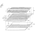
- FIG. 3 is a partial exploded perspective view of the liquid discharge head 26.
- the liquid ejection head 26 according to the first embodiment includes elements related to the nozzles N (illustrative examples of the first nozzles) of the first nozzle row L1 and the nozzles of the second nozzle row L2. This is a structure in which elements related to N (example of the second nozzle) are arranged symmetrically with respect to the virtual plane O.
- first portion a positive portion
- second portion a negative portion
- the structure is substantially common.
- the plurality of nozzles N of the first nozzle row L1 are formed in the first portion P1
- the plurality of nozzles N of the second nozzle row L2 are formed in the second portion P2.
- the virtual plane O corresponds to a boundary surface between the first portion P1 and the second portion P2.
- the liquid discharge head 26 includes a flow path forming unit 30.
- the flow path forming unit 30 is a structure that forms a flow path for supplying ink to the plurality of nozzles N.
- the flow path forming unit 30 of the first embodiment is configured by stacking a communication plate 32 and a pressure chamber forming plate 34 (pressure chamber forming plate).
- Each of the communication plate 32 and the pressure chamber forming plate 34 is a plate-like member that is long in the Y direction.
- a pressure chamber forming plate 34 is installed on the negative surface Fa in the Z direction of the communication plate 32 using, for example, an adhesive.
- a vibrating portion 42 As shown in FIG. 2, on the surface Fa of the communication plate 32, in addition to the pressure chamber forming plate 34, a vibrating portion 42, a plurality of piezoelectric elements 44, a protective member 46, and a housing portion 48 are installed. (Not shown in FIG. 3).
- a nozzle plate 52 and a vibration absorber 54 are installed on the front surface Fb of the communication plate 32 on the positive side in the Z direction (that is, the side opposite to the surface Fa).
- Each element of the liquid discharge head 26 is a plate-like member that is long in the Y direction as in the case of the communication plate 32 and the pressure chamber forming plate 34, and is joined to each other by using, for example, an adhesive.
- the direction in which the communication plate 32 and the pressure chamber forming plate 34 are laminated and the direction in which the communication plate 32 and the nozzle plate 52 are laminated are grasped as the Z direction. It is also possible.
- the nozzle plate 52 is a plate-like member on which a plurality of nozzles N are formed, and is installed on the surface Fb of the communication plate 32 using, for example, an adhesive.
- Each of the plurality of nozzles N is a cylindrical through hole that allows ink to pass therethrough.
- a plurality of nozzles N constituting the first nozzle row L1 and a plurality of nozzles N constituting the second nozzle row L2 are formed.
- a plurality of nozzles N of the first nozzle row L1 are formed along the Y direction in the positive side region in the X direction when viewed from the virtual plane O of the nozzle plate 52, and the negative side region in the X direction.
- the nozzle plate 52 of the first embodiment is a single plate-like member that is continuous over a portion where the plurality of nozzles N of the first nozzle row L1 are formed and a portion where the plurality of nozzles N of the second nozzle row L2 are formed. It is.
- the nozzle plate 52 of the first embodiment is manufactured by processing a silicon (Si) single crystal substrate using a semiconductor manufacturing technique such as dry etching or wet etching. However, known materials and manufacturing methods can be arbitrarily employed for manufacturing the nozzle plate 52.
- the communication plate 32 is formed with a space Ra, a plurality of supply paths 61, and a plurality of communication paths 63 for each of the first portion P1 and the second portion P2.
- the space Ra is an opening formed in an elongated shape along the Y direction in plan view (as viewed from the Z direction), and the supply path 61 and the communication path 63 are through holes formed for each nozzle N.
- the plurality of communication paths 63 are arranged in the Y direction in plan view, and the plurality of supply paths 61 are arranged in the Y direction between the arrangement of the plurality of communication paths 63 and the space Ra.
- the plurality of supply paths 61 communicate with the space Ra in common.
- any one communication path 63 overlaps the nozzle N corresponding to the communication path 63 in plan view. Specifically, any one communication path 63 of the first portion P1 communicates with one nozzle N corresponding to the communication path 63 in the first nozzle row L1. Similarly, any one communication path 63 of the second portion P2 communicates with one nozzle N corresponding to the communication path 63 in the second nozzle row L2.
- the pressure chamber forming plate 34 is a plate-like member in which a plurality of pressure chambers C (cavities) are formed for each of the first portion P1 and the second portion P2.
- the plurality of pressure chambers C are arranged in the Y direction.
- Each pressure chamber C is a rectangular space that is formed for each nozzle N and is long in the X direction in plan view.
- each pressure chamber C is defined by two side surfaces parallel to the YZ plane and an upper surface (ceiling surface) parallel to the XY plane.
- the communication plate 32 and the pressure chamber forming plate 34 are manufactured by processing a single crystal substrate of silicon using, for example, a semiconductor manufacturing technique, similarly to the nozzle plate 52 described above.
- a semiconductor manufacturing technique similarly to the nozzle plate 52 described above.
- known materials and manufacturing methods can be arbitrarily employed for manufacturing the communication plate 32 and the pressure chamber forming plate 34.
- the flow path forming unit 30 (the communication plate 32 and the pressure chamber forming plate 34) and the nozzle plate 52 in the first embodiment include a substrate formed of silicon. Therefore, for example, there is an advantage that a fine flow path can be formed in the flow path forming unit 30 and the nozzle plate 52 with high accuracy by using the semiconductor manufacturing technology as illustrated above.
- a vibrating part 42 is installed on the surface of the pressure chamber forming plate 34 opposite to the communication plate 32.
- the vibration part 42 of the first embodiment is a plate-like member (diaphragm) that can elastically vibrate.
- the pressure chamber forming plate 34 and the vibration part 42 are integrally formed by selectively removing a part in the plate thickness direction in the region corresponding to the pressure chamber C of the plate-like member having a predetermined plate thickness. It is also possible.
- the surface Fa of the communication plate 32 and the vibrating portion 42 are opposed to each other with an interval inside each pressure chamber C.
- the pressure chamber C is a space located between the surface Fa of the communication plate 32 and the vibration part 42, and generates a pressure change in the ink filled in the space.
- Each pressure chamber C is a space whose longitudinal direction is, for example, the X direction, and is formed individually for each nozzle N.
- a plurality of pressure chambers C are arranged in the Y direction for each of the first nozzle row L1 and the second nozzle row L2. As shown in FIG. 2 and FIG. 3, an end portion closer to the imaginary plane O of any one pressure chamber C overlaps the communication path 63 in plan view, and an end portion far from the imaginary plane O is a plane.
- the pressure chamber C communicates with the nozzle N via the communication path 63 and also communicates with the space Ra via the supply path 61. It is also possible to add a predetermined channel resistance by forming a throttle channel having a narrow channel cross-sectional area in the pressure chamber C.
- a plurality of piezoelectric elements 44 corresponding to different nozzles N for each of the first portion P1 and the second portion P2 on the surface of the vibrating portion 42 opposite to the pressure chamber C.
- the piezoelectric element 44 is a passive element that is deformed by supplying a drive signal.
- the plurality of piezoelectric elements 44 are arranged in the Y direction so as to correspond to each pressure chamber C.
- one arbitrary piezoelectric element 44 is a drive element in which a piezoelectric layer 443 is interposed between a first electrode 441 and a second electrode 442 facing each other.
- one of the first electrode 441 and the second electrode 442 can be an electrode that is continuous across the plurality of piezoelectric elements 44 (that is, a common electrode).
- a portion where the first electrode 441, the second electrode 442, and the piezoelectric layer 443 overlap in plan view functions as the piezoelectric element 44.
- a portion that is deformed by a drive signal supplied from the wiring board 28 that is, an active portion that vibrates the vibration portion 42
- the piezoelectric element 44 of the present embodiment functions as a pressure generating unit that generates a pressure change in the pressure chamber C.
- the plurality of piezoelectric elements 44 are divided into a first piezoelectric element and a second piezoelectric element.
- the first piezoelectric elements are a plurality of piezoelectric elements 44 arranged on one side in the X direction (for example, the right side in FIG. 2) when viewed from the virtual plane O.
- the second piezoelectric elements are a plurality of piezoelectric elements 44 arranged on the other side in the X direction (for example, the left side in FIG. 2) when viewed from the virtual plane O.
- the protective member 46 is a plate-like member for protecting the plurality of piezoelectric elements 44, and is installed on the surface of the vibration part 42 (or the surface of the pressure chamber forming plate 34).
- the material and manufacturing method of the protective member 46 are arbitrary, the protective member 46 is formed by processing, for example, a silicon (Si) single crystal substrate by a semiconductor manufacturing technique, like the communication plate 32 and the pressure chamber forming plate 34. obtain.
- a plurality of piezoelectric elements 44 are accommodated in a recess formed in the surface of the protection member 46 on the vibration part 42 side.
- the end of the wiring board 28 is joined to the surface of the vibrating part 42 opposite to the flow path forming part 30 (or the surface of the flow path forming part 30).
- the wiring board 28 is a flexible mounting component on which a plurality of wirings (not shown) that electrically connect the control unit 20 and the liquid ejection head 26 are formed.
- a flexible wiring board 28 such as FPC (Flexible Printed Circuit) or FFC (Flexible Flat Cable) is preferably used.
- the housing portion 48 is a case for storing ink supplied to the plurality of pressure chambers C (and the plurality of nozzles N).
- the surface on the positive side in the Z direction of the housing portion 48 is joined to the surface Fa of the communication plate 32 with an adhesive, for example.
- a known technique or manufacturing method can be arbitrarily employed for manufacturing the casing 48.
- the housing part 48 can be formed by injection molding of a resin material.
- a space Rb is formed for each of the first part P1 and the second part P2.
- the space Rb of the casing 48 and the space Ra of the communication plate 32 communicate with each other.
- a space constituted by the space Ra and the space Rb functions as a liquid storage chamber R (reservoir) that stores ink supplied to the plurality of pressure chambers C.
- the liquid storage chamber R is a common liquid chamber shared by the plurality of nozzles N.
- a liquid storage chamber R is formed in each of the first portion P1 and the second portion P2.
- the liquid storage chamber R of the first portion P1 is located on the positive side in the X direction when viewed from the virtual plane O, and the liquid storage chamber R of the second portion P2 is positioned on the negative side in the X direction when viewed from the virtual surface O.
- An inlet 482 for introducing the ink supplied from the liquid container 14 into the liquid storage chamber R is formed on the surface of the casing 48 opposite to the communication plate 32.
- a vibration absorber 54 is installed for each of the first part P1 and the second part P2.
- the vibration absorber 54 is a flexible film (compliance substrate) that absorbs pressure fluctuations of ink in the liquid storage chamber R.
- the vibration absorber 54 is installed on the surface Fb of the communication plate 32 so as to close the space Ra of the communication plate 32 and the plurality of supply passages 61 (specifically, the wall surface of the liquid storage chamber R (specifically, Constitutes the bottom surface.
- a space constituting the circulating fluid chamber 65 is formed on the surface Fb of the communication plate 32 facing the nozzle plate 52.
- the circulating liquid chamber 65 of the first embodiment liquid is a long groove-shaped bottomed hole extending in the Y direction in plan view. The opening of the circulating fluid chamber 65 is closed by the nozzle plate 52 joined to the surface Fb of the communication plate 32.
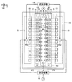
- FIG. 5 is a configuration diagram of the liquid discharge head 26 focusing on the circulating fluid chamber 65.
- the circulating fluid chamber 65 is continuous over a plurality of nozzles N along the first nozzle row L1 and the second nozzle row L2.
- the circulating fluid chamber 65 is formed between the arrangement of the plurality of nozzles N in the first nozzle row L1 and the arrangement of the plurality of nozzles N in the second nozzle row L2. Therefore, as shown in FIG. 2, the circulating fluid chamber 65 is located between the communication path 63 of the first part P1 and the communication path 63 of the second part P2.
- the circulating fluid chamber 65 extends in the Y direction so as to be continuous over the plurality of pressure chambers C or the plurality of piezoelectric elements 44 in each of the first portion P1 and the second portion P2.
- the circulating fluid chamber 65 and the liquid storage chamber R extend in the Y direction with a space therebetween, and the pressure chamber C, the communication path 63, and the nozzle N are disposed within the space. It is also possible that and are located.
- the flow path forming unit 30 of the first embodiment includes the pressure chamber C (example of the first pressure chamber) and the communication path 63 (example of the first communication path) in the first portion P1, and the second part P2. Circulation located between the pressure chamber C (example of the second pressure chamber) and the communication path 63 (example of the second communication path) and the communication path 63 of the first portion P1 and the communication path 63 of the second portion P2.
- This is a structure in which a liquid chamber 65 is formed.
- the flow path forming unit 30 according to the first embodiment includes a partition wall 69 that partitions the circulating fluid chamber 65 and each communication path 63.
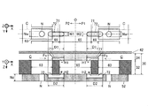
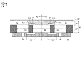
- FIG. 6 is an enlarged plan view and cross-sectional view of a portion of the liquid discharge head 26 in the vicinity of the circulating fluid chamber 65.
- a plurality of first circulation paths 71 that connect the pressure chamber C to the circulating fluid chamber 65 are formed on the surface of the pressure chamber forming plate 34 that faces the communication plate 32.
- a plurality of first circulation paths 71 are arranged for each of the first portion P1 and the second portion P2.
- the plurality of first circulation paths 71 of the first portion P1 correspond to the plurality of pressure chambers C of the first nozzle row L1 on a one-to-one basis.
- the plurality of first circulation paths 71 in the second portion P2 correspond to the plurality of pressure chambers C in the second nozzle row L2 on a one-to-one basis.
- a plurality of second circulation paths 72 that communicate the communication path 63 with the circulating fluid chamber 65 are formed on the surface of the nozzle plate 52 that faces the flow path forming unit 30.
- a plurality of second circulation paths 72 are arranged for each of the first portion P1 and the second portion P2.
- the plurality of second circulation paths 72 of the first portion P1 correspond to the plurality of communication paths 63 of the first nozzle row L1 on a one-to-one basis.
- the plurality of second circulation paths 72 of the second portion P2 correspond to the plurality of communication paths 63 of the second nozzle row L2 on a one-to-one basis.
- Each of the first circulation path 71 and the second circulation path 72 is a groove portion (that is, a long bottomed hole) extending in the X direction, and functions as a flow path for circulating ink.
- the first circulation path 71 and the second circulation path 72 are formed away from the nozzle N on the circulating fluid chamber 65 side when viewed from the nozzle N in plan view. Since the plurality of first circulation paths 71 and the plurality of pressure chambers C are arranged on the pressure chamber forming plate 34, for example, the plurality of first circulation paths 71 and the plurality of pressure chambers C are collectively processed in a common process by a semiconductor manufacturing technique. Can be formed.
- the plurality of second circulation paths 72 and the plurality of nozzles N are arranged on the nozzle plate 52, the plurality of first circulation paths 71 and the plurality of nozzles N can be collectively formed in a common process by semiconductor manufacturing technology, for example. .
- the liquid ejection device 100 of the first embodiment includes a circulation mechanism 75.
- the circulation mechanism 75 is a mechanism for returning the ink in the circulation liquid chamber 65 to the liquid storage chamber R and circulating it.
- the circulation mechanism 75 of the first embodiment includes, for example, a suction mechanism (for example, a pump) for sucking ink from the circulating fluid chamber 65, a filter mechanism for collecting bubbles and foreign matters mixed in the ink, and thickening by heating the ink. And a heating mechanism for reducing (not shown). Ink from which bubbles and foreign matter have been removed by the circulation mechanism 75 and whose viscosity has been reduced is supplied from the circulation mechanism 75 to the liquid storage chamber R through the introduction port 482.
- the ink circulates through the path of the liquid storage chamber R ⁇ the supply path 61 ⁇ the pressure chamber C ⁇ the first circulation path 71 ⁇ the circulation liquid chamber 65 ⁇ the circulation mechanism 75 ⁇ the liquid storage chamber R. Further, the ink circulates through the path of the liquid storage chamber R ⁇ the supply path 61 ⁇ the pressure chamber C ⁇ the communication path 63 ⁇ the second circulation path 72 ⁇ the circulation liquid chamber 65 ⁇ the circulation mechanism 75 ⁇ the liquid storage chamber R.
- the circulation mechanism 75 of the first embodiment sucks ink from both sides of the circulating fluid chamber 65 in the Y direction. That is, the circulation mechanism 75 sucks ink from the vicinity of the negative end portion in the Y direction of the circulating fluid chamber 65 and the vicinity of the positive end portion of the circulating fluid chamber 65 in the Y direction.
- the circulation mechanism 75 sucks ink from the vicinity of the negative end portion in the Y direction of the circulating fluid chamber 65 and the vicinity of the positive end portion of the circulating fluid chamber 65 in the Y direction.
- a difference in ink pressure occurs between both ends of the circulating fluid chamber 65, and the pressure difference in the circulating fluid chamber 65 is reduced.
- the pressure of the ink in the communication path 63 may differ depending on the position in the Y direction.
- the ejection characteristics (for example, ejection amount and ejection speed) of ink from each nozzle N may differ depending on the position in the Y direction.
- the pressure difference inside the circulating fluid chamber 65 is reduced. Therefore, it is possible to approximate the ink ejection characteristics with high accuracy over the plurality of nozzles N arranged in the Y direction.
- the ink may be sucked from one end of the circulating fluid chamber 65.
- the nozzle N is discharged to the outside, and the remaining part flows into the circulating fluid chamber 65.
- the first embodiment not only the flow flowing from the communication path 63 into the circulating fluid chamber 65 via the second circulation path 72 (the flow indicated by the thick broken arrow in FIG. 6), but also the pressure circuit C to the first circulation path.
- a flow that flows into the circulating fluid chamber 65 via 71 also occurs.
- not only the communication path 63 but also the bubbles and the thickened ink that have entered the pressure chamber C can be discharged to the circulating fluid chamber 65, so that ejection failure of the nozzle N can be effectively suppressed.
- the ink may be circulated through the circulation liquid chamber 65. Ink flows through the first circulation path 71 and the second circulation path 72 in the same manner. Therefore, when ink sedimentation or thickening occurs in the communication path 63, it is difficult for foreign matter or thickened ink due to the sedimentation to be discharged to the circulating fluid chamber 65.
- the flow path resistance of the second circulation path 72 is made smaller than the flow path resistance of the first circulation path 71.
- ink that is likely to generate foreign matter due to sedimentation for example, pigment ink
- ink containing a solvent that is more volatile than moisture is likely to thicken, and drying tends to proceed at the meniscus in the nozzle N, which is the gas-liquid interface between the ink and air. Ink thickening is likely to proceed.
- ink flows more easily in the second circulation path 72 near the nozzle N than in the first circulation path 71 near the pressure chamber C. Foreign matter accumulated in the vicinity and ink having increased viscosity are easily discharged from the second circulation path 72 to the circulating fluid chamber 65 along the ink flow.
- the flow path cross-sectional area of the second circulation path 72 is larger than the flow path cross-sectional area of the first circulation path 71.
- the flow path width W2 in the Y direction of the second circulation path 72 shown in FIG. 6 is larger than the flow path width W1 in the Y direction of the first circulation path 71 (dimension in the Y direction).
- the flow path height H2 in the Z direction of the second circulation path 72 is larger than the flow path height H1 in the Z direction of the first circulation path 71.
- the second circulation path 72 is set by making the flow path width W2 and the flow path height H2 of the second circulation path 72 larger than the flow path width W1 and the flow path height H1 of the first circulation path 71.
- the flow path cross-sectional area of the first circulation path 71 can be made larger.
- the channel height H1 and the channel height H2 are constant over the entire length in the X direction.
- the flow path resistance of the second circulation path 72 can be made smaller than the flow path resistance of the first circulation path 71. Accordingly, the second circulation path 72 is easier to flow ink than the first circulation path 71, so that foreign matter accumulated in the vicinity of the nozzle N in the communication path 63 and thickened ink are removed from the second circulation path 72.
- the flow path length D2 in the X direction of the second circulation path 72 may be shorter than the flow path length D1 in the X direction of the first circulation path 71. Also with this configuration, the flow path resistance of the second circulation path 72 can be made smaller than the flow path resistance of the first circulation path 71.
- the cross-sectional area of the nozzle N of the first embodiment (the cross-sectional area of the cross section perpendicular to the Z direction) is larger than the cross-sectional area of the first circulation path 71 (the cross-sectional area of the cross section perpendicular to the X direction). It is larger than the cross-sectional area of the second circulation path 72 (the cross-sectional area of the cross section perpendicular to the X direction).
- the flow path cross-sectional area of the nozzle N is changed to the first circulation path 71. Larger than the cross-sectional area of the channel.
- the flow path sectional area of the nozzle N is made larger than the flow path sectional area of the second circulation path 72.
- the flow path resistance of the nozzle N can be made smaller than the flow path resistance of the first circulation path 71 and smaller than the flow path resistance of the second circulation path 72. Accordingly, when ink is ejected, the ink can flow more easily to the nozzle N than the first circulation path 71 and the second circulation path 72, so that the ink ejection amount from the nozzle N can be increased.
- the flow path length Nd in the Y direction of the nozzle N is shorter than the flow path length D1 in the X direction of the first circulation path 71, and the flow path in the X direction of the second circulation path 72. It may be shorter than the length D2. Also with this configuration, the flow path resistance of the nozzle N can be made smaller than the flow path resistance of the first circulation path 71 and smaller than the flow path resistance of the second circulation path 72.
- the pressure chamber C and the first circulation path 71 of the first embodiment are arranged as follows. That is, the pressure chamber C extends in the second direction along a plane orthogonal to the first direction.
- the first circulation path 71 extends from the pressure chamber C in a plan view (as viewed from the Z direction) and extends in a direction intersecting the first direction.
- the first direction is a direction serving as a reference for the extending direction of the pressure chamber C and the extending direction of the first circulation path 71, and is exemplified as the Z direction in the present embodiment.
- the second direction is a direction along the XY plane orthogonal to the Z direction, which is an example of the first direction, and is exemplified as the X direction in the present embodiment.
- the 1st direction (Z direction) of this embodiment was a perpendicular direction was illustrated, the 1st direction may not be a perpendicular direction.
- the direction in which the first circulation path 71 extends can be matched with the direction in which the pressure chamber C extends. Therefore, when the flow from the pressure chamber C to the first circulation path 71 is formed, the direction of the ink flow through the first circulation path 71 and the direction of the ink flow in the pressure chamber C do not change significantly. In other words, the flow from the pressure chamber C to the first circulation channel 71 can be formed at an angle smaller than 90 degrees.
- the direction of the ink flow through the first circulation path 71 and the direction of the ink flow in the pressure chamber C can be brought close to each other, the area where ink stagnates in the pressure chamber C can be reduced. Thereby, the bubbles in the pressure chamber C can be easily discharged to the circulating fluid chamber 65. In addition, it is possible to make it difficult for bubbles to enter the pressure chamber C from the first circulation path 71 as compared with the case where the circulating fluid chamber 65 is connected by a vertical flow path extending in the vertical direction from the lower side of the pressure chamber C.
- the first circulation path 71 extends in the X direction, which is the direction in which the pressure chamber C extends from the pressure chamber C in plan view.
- the first circulation path 71 extends in the same X direction as the direction of ink flow in the pressure chamber C. Therefore, the first circulation path 71 as indicated by a thick broken line arrow.
- the direction of the ink flow through the pressure chamber C can be the same X direction as the direction of the ink flow in the pressure chamber C.
- the circulating fluid chamber 65 is connected to the circulating fluid chamber 65 through the vertical flow path from the lower side of the pressure chamber C, it is possible to reduce the area where ink stagnates in the pressure chamber C.
- the liquid chamber 65 can be easily discharged.
- the first circulation path 71 is connected to one of the two side surfaces in the X direction of the pressure chamber C (the side surface closer to the virtual surface O). .
- the first circulation path 71 is connected to one of the two side surfaces in the X direction of the pressure chamber C (the side surface closer to the virtual surface O).
- the two side surfaces in the X direction of the pressure chamber C of the first embodiment are inclined surfaces that are inclined so that the height (dimension in the Z direction) of the pressure chamber C increases toward the inside of the pressure chamber C.
- Fc is formed.
- the inclined surface Fc is formed at a portion where each of the two side surfaces of the pressure chamber C in the X direction intersects with the upper surface of the pressure chamber C (the surface on the positive side in the Z direction of the vibration unit 42). The case is illustrated. That is, the inclined surface Fc is formed at the corner where the upper surface and the side surface of the pressure chamber C intersect.
- Each inclined surface Fc intersects the upper surface of the pressure chamber C and is inclined inward of the pressure chamber C so as to face the lower surface of the pressure chamber C obliquely.
- the inclined surface Fc may be a flat surface or a curved surface.
- the ink can easily flow. Further, by forming the inclined surface Fc on the side surface to which the first circulation path 71 is connected, it is easy to guide the bubbles that have entered the pressure chamber C to the first circulation path 71 along the inclined surface Fc. Accordingly, the bubbles that have entered the pressure chamber C are easily discharged from the first circulation path 71.
- the first circulation path 71 of the first embodiment is formed in the pressure chamber forming plate 34 of the flow path forming unit 30, the first circulation path 71 extends in a direction along the direction of ink flow in the pressure chamber C. Easy to place.
- the amount of ink discharged through the nozzle N is the first of the ink flowing through the communication path 63.
- the inertance of the communication path 63, the nozzle N, the first circulation path 71, and the second circulation path 72 is increased so as to exceed the circulation amount of the ink flowing into the circulation liquid chamber 65 via the circulation path 71 and the second circulation path 72. Selected.
- the communication path 63 and the nozzle are set so that the ratio of the circulation amount of the ink flowing through the communication path 63 from the pressure chamber C is 70% or more (the ratio of the discharge amount is 30% or less).
- N the flow path resistance of each of the first circulation path 71 and the second circulation path 72 is determined. According to the above configuration, it is possible to effectively circulate the ink in the vicinity of the nozzle N to the circulating liquid chamber 65 while ensuring the ink discharge amount.
- the ratio between the ink discharge amount and the circulation amount described above is not limited to 70%, and can be adjusted by the flow path resistance of the first circulation path 71 and the second circulation path 72.
- the discharge amount can be increased while the circulation amount is decreased, and the flow paths of the first circulation path 71 and the second circulation path 72 are increased.
- the flow path resistance of the second circulation path 72 is set to be different from that of the first circulation path by changing the flow path cross-sectional area or the flow path length between the first circulation path 71 and the second circulation path 72.
- the opening area A2 of the flow path opening on the pressure chamber C side of the second circulation path 72 is larger than the opening area A1 of the flow path opening on the communication path 63 side of the first circulation path 71. May also be increased.
- a throttle channel 712 having a narrow channel cross-sectional area may be provided in a part of the first circulation channel 71. 7 and 8, the flow path resistance of the second circulation path 72 can be made smaller than the flow path resistance of the first circulation path 71.
- the first circulation path 71 of the first embodiment overlaps the second circulation path 72 in plan view (as viewed from the Z direction).
- the first circulation path 71 may overlap the entire second circulation path 72 or may overlap a part thereof.
- the first circulation path 71 and the second circulation path 72 are arranged not to overlap in plan view.
- the liquid discharge head 26 can be downsized in the direction along the XY plane.
- the liquid discharge head 26 is turned upside down so that the nozzle N is on the top, the bubbles can be discharged.
- the case where the liquid discharge head 26 is turned upside down is not only the case where the liquid discharge head 26 is turned upside down while being removed from the liquid discharge apparatus 100 but also the case where the liquid discharge head 26 is turned upside down. included.
- the first circulation path 71 is disposed so as to overlap the second circulation path 72 in plan view. Therefore, when the liquid ejection head 26 is turned upside down, the bubbles in the pressure chambers move through the communication path 63 by buoyancy. Since it moves to the nozzle N side, it is discharged from the nozzle N.
- the first circulation path 71 and the second circulation path 72 are turned upside down by turning the liquid ejection head 26 upside down. Accordingly, since the first circulation path 71 is on the pressure chamber C side below the communication path 63, the foreign matter and the thickened ink dropped from the communication path 63 to the pressure chamber C are transferred from the first circulation path 71 to the circulating fluid chamber 65. It becomes easy to be discharged.
- the first circulation path 71 and the second circulation path 72 of the first embodiment are parallel to each other in the vertical direction and are arranged so as to extend in the horizontal direction, the liquid ejection head 26 can be turned upside down. The direction in which the first circulation path 71 and the second circulation path 72 extend does not change.
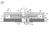
- FIG. 9 is a cross-sectional view of the liquid ejection head 26 according to the second embodiment cut along a cross section perpendicular to the Y direction, and corresponds to FIG.
- the liquid discharge head 26 of the second embodiment and the liquid discharge head 26 of the first embodiment have different flow path configurations. That is, in the first embodiment, the flow path configuration in which ink is introduced into the pressure chamber C by the supply path 61 extending in the Z direction from below the pressure chamber C is illustrated. In the second embodiment, a flow path configuration in which ink is introduced into the pressure chamber C by the supply path 61 extending in the X direction from the side of the pressure chamber C is illustrated.
- the first part P1 and the second part P2 shown in FIG. 9 have a flow path configuration corresponding to one nozzle N.
- the configuration of the first portion P1 and the second portion P2 reversed between the positive side and the negative side in the X direction with respect to FIG. 9 and the configuration of the first portion P1 and the second portion P2 similar to FIG. Are alternately arranged.
- a plurality of configurations of the first portion P1 and the second portion P2 similar to those in FIG. 9 may be arranged side by side in the Y direction.
- the liquid storage chamber R of the first portion P1 shown in FIG. 9 is configured by a space Rb formed in the first portion P1 of the casing 48.
- the liquid storage chamber R of the second part P2 is configured by a space Rb formed in the second part P2 of the casing 48.
- the supply path 61 of the first portion P1 in FIG. 9 communicates the liquid storage chamber R with the positive side surface of the pressure chamber C in the X direction.
- the second circulation path 72 of FIG. 9 penetrates the partition wall 69 from the communication path 63 on the positive side in the X direction to the circulating fluid chamber 65 on the negative side in the X direction on the surface of the communication plate 32 facing the nozzle plate 52. Formed.
- the second circulation path 72 may be formed in the nozzle plate 52 as in the configuration of FIG. 2.
- the first circulation path 71 shown in FIG. 9 is formed on the surface of the pressure chamber forming plate 34 facing the communication plate 32 as in the configuration of FIG. 2, and communicates the pressure chamber C with the circulating fluid chamber 65.
- the pressure chamber C, the supply path 61, the communication path 63, and the nozzle N are not formed in the 2nd part P2 of FIG.
- the flow path resistance of the second circulation path 72 can be made smaller than the flow path resistance of the first circulation path 71.
- foreign matter and thickened ink due to ink settling that tends to collect in the vicinity of the nozzles N in the communication path 63 are easily discharged from the second circulation path 72 to the circulating fluid chamber 65, so that the foreign matter and thickened ink are efficiently removed. It can be discharged.
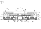
- FIG. 10 is a cross-sectional view of the liquid ejection head 26 according to the third embodiment cut along a cross section perpendicular to the Y direction, and corresponds to FIG.
- the liquid ejection head 26 according to the third embodiment and the liquid ejection head 26 according to the first embodiment are different in the wiring structure for supplying a drive signal for the piezoelectric element 44. That is, in the first embodiment, the case where the drive signal is supplied to the piezoelectric element 44 by the wiring board 28 is illustrated.
- the third embodiment exemplifies a case where the drive IC 29 is mounted on the protection member 46 and wiring between the drive IC 29 and the piezoelectric element 44 is provided on the protection member 46.
- the drive IC 29 is electrically connected to the control unit 20 by a flexible wiring board such as an FPC (Flexible Printed Circuit) or FFC (Flexible Flat Cable).
- FPC Flexible Printed Circuit
- FFC Flexible Flat Cable
- the drive IC 29 is a substantially rectangular IC chip that drives each piezoelectric element 44 by generating and supplying a drive signal for the piezoelectric element 44 under the control of the control unit 20. At least a part of the piezoelectric elements 44 of the liquid discharge head 26 overlaps the drive IC 29 in plan view. 10 is provided with a plurality of connection terminals 464 and a plurality of wirings 466 for electrically connecting the drive IC 29 and each piezoelectric element 44, and the protection member 46 of the third embodiment includes: It also functions as a wiring board.
- the plurality of wirings 466 are divided into a wiring 466a and a wiring 466b.
- the connection terminal 464 is divided into a connection terminal 464a electrically connected to the wiring 466a and a connection terminal 464b electrically connected to the wiring 466b.
- the wiring 466a is a wiring connected to the output terminal of the base voltage of the drive IC 29, and is continuously formed in the Y direction across the plurality of piezoelectric elements 44.
- connection terminal 464a connects the first electrode 441, which is a common electrode of each piezoelectric element 44, and the wiring 466a. Accordingly, the first electrode 441 of each piezoelectric element 44 is connected to the output terminal of the base voltage of the drive IC 29 via the connection terminal 464a and the wiring 466a. Accordingly, the base voltage output from the output terminal of the drive IC 29 is applied to the first electrode 441 of each piezoelectric element 44 via the wiring 466a and the connection terminal 464a.
- connection terminal 464b connects the second electrode 442, which is an individual electrode of each piezoelectric element 44, and the wiring 466b.
- the second electrode 442 of each piezoelectric element 44 is connected to the drive signal output terminal of the drive IC 29 via the connection terminal 464b and the wiring 466b. Therefore, the drive signal output from the output terminal of the drive IC 29 is applied to the second electrode 442 of each piezoelectric element 44 via the connection terminal 464b and the wiring 466b.
- each of the connection terminals 464a and 464b is formed of a resin core bump in which a protrusion formed of, for example, a resin material is covered with a conductive material.
- the connection terminals 464a and 464b are not limited to resin core bumps, and may be formed of metal bumps.
- the connection terminal 464 of the present embodiment is disposed so as to overlap the first circulation path 71 or the circulating fluid chamber 65 in plan view (as viewed from the Z direction). According to this, even when the wiring 466 and the connection terminal 464 generate heat due to the current flowing through the wiring 466 and the connection terminal 464 by driving the piezoelectric element 44, the heat from the wiring 466 and the connection terminal 464 is transferred to the first circulation. It can be efficiently discharged to the circulating fluid chamber 65 by being put on the ink flow in the path 71.
- the flow path resistance of the second circulation path 72 can be made smaller than the flow path resistance of the first circulation path 71.
- foreign matter and thickened ink due to ink settling that tends to collect in the vicinity of the nozzles N in the communication path 63 are easily discharged from the second circulation path 72 to the circulating fluid chamber 65, so that the foreign matter and thickened ink are efficiently removed. It can be discharged.
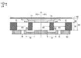
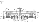
- FIG. 11 is a cross-sectional view of the liquid ejection head 26 according to the fourth embodiment cut along a cross section perpendicular to the Y direction, and corresponds to FIG.
- the liquid discharge head 26 according to the fourth embodiment and the liquid discharge head 26 according to the first embodiment have different flow path configurations. That is, in the first embodiment, the case where one circulating fluid chamber 65 is provided is illustrated, but in the fourth embodiment, a case where a plurality of circulating fluid chambers are provided is illustrated.
- FIG. 11 illustrates the case where one circulating fluid chamber 65a (first circulating fluid chamber) and two circulating fluid chambers 65b (second circulating fluid chamber) are formed on the communication plate 32.
- the circulating fluid chamber 65a is formed between the nozzle N of the first nozzle row L1 and the nozzle N of the second nozzle row L2 in the communication plate 32, and corresponds to the circulating fluid chamber 65 of FIG.
- One of the two circulating fluid chambers 65b is formed between the nozzle N of the first nozzle row L1 and the supply path 61 on the first portion P1 side of the communication plate 32.
- the other circulating fluid chamber 65b is formed between the nozzle N of the second nozzle row L2 and the supply path 61 on the second portion P2 side of the communication plate 32.
- the circulating fluid chamber 65b is a long bottomed hole (groove) that is formed on the opposite side of the circulating fluid chamber 65 with the communication passage 63 and the nozzle N interposed therebetween and extends in the Y direction.
- the nozzle plate 52 joined to the surface Fb of the communication plate 32 closes the openings of the circulating fluid chamber 65a and the circulating fluid chamber 65b.
- a plurality of first circulation paths 71 are formed on the surface of the pressure chamber forming plate 34 of FIG. 11 that faces the communication plate 32, and the pressure chamber C communicates with the circulating fluid chamber 65a.
- the plurality of first circulation paths 71 of the first portion P1 correspond to the plurality of pressure chambers C of the first nozzle row L1 on a one-to-one basis.
- the plurality of first circulation paths 71 in the second portion P2 correspond to the plurality of pressure chambers C in the second nozzle row L2 on a one-to-one basis.
- a plurality of second circulation paths 72a that connect the communication path 63 to the circulating fluid chamber 65a are formed on the surface of the nozzle plate 52 in FIG.
- a plurality of second circulation paths 72a are arranged for each of the first portion P1 and the second portion P2.
- the plurality of second circulation paths 72a of the first portion P1 correspond to the plurality of communication paths 63 of the first nozzle row L1 on a one-to-one basis.
- the plurality of second circulation paths 72a in the second portion P2 correspond to the plurality of communication paths 63 in the second nozzle row L2 on a one-to-one basis.
- a plurality of second circulation paths 72b that connect the communication path 63 to the circulating fluid chamber 65b are formed on the surface of the nozzle plate 52 of FIG.
- a plurality of second circulation paths 72b are arranged for each of the first portion P1 and the second portion P2.
- the plurality of second circulation paths 72b of the first portion P1 corresponds to the plurality of communication paths 63 of the first nozzle row L1 on a one-to-one basis.
- the plurality of second circulation paths 72b in the second portion P2 correspond to the plurality of communication paths 63 in the second nozzle row L2 on a one-to-one basis.
- the ink circulates through the path flowing from the communication path 63 to the circulating liquid chamber 65a via the second circulation path 72a, and from the communication path 63 via the second circulation path 72b.
- the ink also circulates through the path flowing through the circulating fluid chamber 65b. Accordingly, the foreign matter and the thickened ink due to the sedimentation of the ink that easily collects in the vicinity of the nozzle N in the communication path 63 can be discharged not only from the circulating fluid chamber 65a but also from the circulating fluid chamber 65b. Accordingly, it is possible to improve the dischargeability of foreign matter and thickened ink.
- the first circulation path 71 communicates the pressure chamber C with the circulating fluid chamber 65a, and the second circulation path 72b connects the communication passage 63 with the circulating fluid chamber 65b. It is also possible to have a configuration that communicates with.
- the second circulation paths 72 a and 72 b may be formed in the flow path forming unit 30.
- the case where the 2nd circulation paths 72a and 72b are formed in the communicating plate 32 is illustrated.
- the case where the second circulation path 72b is arranged along the X direction in the same manner as the second circulation path 72a is illustrated, but for example, as in the third modification shown in FIG.
- the two circulation paths 72b may be inclined so as to intersect the X direction.
- the piezoelectric liquid ejection head 26 using the piezoelectric element that imparts mechanical vibration to the pressure chamber as the pressure generating unit is exemplified, but bubbles are generated inside the pressure chamber by heating. It is also possible to employ a heat-type liquid discharge head using a heat generating element as a pressure generating unit.
- the liquid ejection apparatus 100 exemplified in the above-described embodiment can be employed in various apparatuses such as a facsimile apparatus and a copier, in addition to apparatuses dedicated to printing.
- the use of the liquid ejection apparatus 100 of the present invention is not limited to printing.
- a liquid ejection device that ejects a solution of a coloring material is used as a manufacturing apparatus that forms a color filter of a liquid crystal display device, an organic EL (Electro Luminescence) display, an FED (surface emitting display), or the like.
- a liquid discharge apparatus that discharges a solution of a conductive material is used as a manufacturing apparatus that forms wiring and electrodes of a wiring board. Further, it is also used as a chip manufacturing apparatus that discharges a bioorganic solution as a kind of liquid.
- SYMBOLS 100 Liquid ejection apparatus, 12 ... Medium, 14 ... Liquid container, 20 ... Control unit, 22 ... Conveyance mechanism, 24 ... Movement mechanism, 242 ... Carriage, 244 ... Conveyance belt, 26 ... Liquid ejection head, 28 ... Wiring board, DESCRIPTION OF SYMBOLS 29 ... Drive IC, 30 ... Flow path formation part, 32 ... Communication board, 34 ... Pressure chamber formation board, 42 ... Vibrating part, 44 ... Piezoelectric element, 441 ... 1st electrode, 442 ... 2nd electrode, 443 ... Piezoelectric body 46, protective member, 464 ... connecting terminal, 464a ...
Abstract
Provided is a liquid discharge head which can more efficiently discharge foreign matter and increased-viscosity ink. A liquid discharge head (26) comprises: a flow passage forming section (30) provided with a nozzle plate (52) to which a nozzle (N) is provided, a pressure chamber (C) to which liquid is supplied, a communication passage (63) which connects the pressure chamber (C) to the nozzle (N), and a circulation liquid chamber (65); a pressure generation section which generates a change in pressure in the pressure chamber (C); a first circulation passage (71) which connects the pressure chamber (C) to the circulation liquid chamber (65); and a second circulation passage (72) which connects the communication passage (63) to the circulation liquid chamber (65). The flow resistance of the second circulation passage (72) is lower than that of the first circulation passage (71).
Description
本発明は、インク等の液体を吐出する技術に関する。
The present invention relates to a technique for discharging a liquid such as ink.
圧電素子などの駆動素子によって圧力室内に圧力変化を生じさせることで圧力室内のインクなどの液体をノズルから吐出させる液体吐出ヘッドが知られている。このような液体吐出ヘッドでは、液体に気泡が混入したり、液体が増粘したりすることで、ノズルの吐出不良が発生する虞がある。例えば特許文献1では、圧力室の下側に循環流路(供給支流路と回収支流路)を配置し、圧力室とノズルとをそれぞれ別々の流路(第1の回収絞り流路、第2の回収絞り流路)で循環流路に連通する。これにより、循環流路を通って循環する液体の流れを形成することで、液体の増粘を抑制している。
A liquid discharge head that discharges a liquid such as ink in a pressure chamber from a nozzle by causing a pressure change in the pressure chamber by a driving element such as a piezoelectric element is known. In such a liquid discharge head, there is a possibility that nozzle discharge defects may occur due to bubbles mixed in the liquid or the viscosity of the liquid increasing. For example, in Patent Document 1, a circulation flow path (a supply branch flow path and a recovery branch flow path) is disposed below the pressure chamber, and the pressure chamber and the nozzle are separated from each other (a first recovery throttle flow path, a second recovery flow path). The recovery throttle channel) communicates with the circulation channel. Thereby, the increase in the viscosity of the liquid is suppressed by forming a flow of the liquid that circulates through the circulation flow path.
しかしながら、特許文献1のように複数の流路によって循環流路を圧力室やノズルに連通する場合には、循環流路に連通する各流路の流路抵抗がほとんど変わらないと、循環流路を介して液体を循環させても、各流路には同じように液体が流れてしまう。したがって、液体の沈降や増粘が発生した場合に、その沈降による異物や増粘した液体がノズル近傍から循環流路に排出され難くなってしまう。
However, when the circulation channel is communicated with the pressure chambers and nozzles by a plurality of channels as in Patent Document 1, the circulation channel is almost the same as the channel resistance of each channel communicating with the circulation channel is not changed. Even if the liquid is circulated through the channel, the liquid flows in the same way in each flow path. Therefore, when liquid sedimentation or thickening occurs, it becomes difficult for foreign matter or thickened liquid due to the sedimentation to be discharged from the vicinity of the nozzle to the circulation channel.
以上の課題を解決するために、本発明の好適な態様に係る液体吐出ヘッドは、ノズルが設けられたノズル板と、液体が供給される圧力室と、圧力室をノズルに連通する連通路と、循環液室とが設けられた流路形成部と、圧力室の圧力変化を発生させる圧力発生部と、圧力室を循環液室に連通する第1循環路と、連通路を循環液室に連通する第2循環路と、を備え、第2循環路の流路抵抗は、第1循環路の流路抵抗よりも小さい。
In order to solve the above problems, a liquid discharge head according to a preferred aspect of the present invention includes a nozzle plate provided with a nozzle, a pressure chamber to which a liquid is supplied, and a communication path that communicates the pressure chamber with the nozzle. A flow path forming portion provided with a circulating fluid chamber, a pressure generating portion that generates a pressure change in the pressure chamber, a first circulation path that connects the pressure chamber to the circulating fluid chamber, and a communicating passage as the circulating fluid chamber. A second circulation path that communicates, and the flow path resistance of the second circulation path is smaller than the flow path resistance of the first circulation path.
<第1実施形態>
図1は、本発明の第1実施形態に係る液体吐出装置100を例示する構成図である。第1実施形態の液体吐出装置100は、液体の例示であるインクを媒体12に吐出するインクジェット方式の印刷装置である。媒体12は、典型的には印刷用紙であるが、樹脂フィルムまたは布帛等の任意の材質の印刷対象を媒体12とすることもできる。図1に示すように、液体吐出装置100には、インクを貯留する液体容器14が設置される。例えば液体吐出装置100に着脱可能なカートリッジ、可撓性のフィルムで形成された袋状のインクパック、またはインクを補充可能なインクタンクが液体容器14として利用される。色彩が相違する複数種のインクが液体容器14には貯留される。インクは、色材として染料が含まれる染料インクでも、色材として顔料が含まれる顔料インクでもよい。 <First Embodiment>
FIG. 1 is a configuration diagram illustrating aliquid ejection apparatus 100 according to the first embodiment of the invention. The liquid ejection apparatus 100 according to the first embodiment is an ink jet printing apparatus that ejects ink, which is an example of a liquid, onto the medium 12. The medium 12 is typically a printing paper, but the medium 12 can be a printing target of an arbitrary material such as a resin film or a fabric. As shown in FIG. 1, the liquid ejection apparatus 100 is provided with a liquid container 14 that stores ink. For example, a cartridge that can be attached to and detached from the liquid ejection device 100, a bag-like ink pack formed of a flexible film, or an ink tank that can be refilled with ink is used as the liquid container 14. A plurality of types of inks having different colors are stored in the liquid container 14. The ink may be a dye ink containing a dye as a color material or a pigment ink containing a pigment as a color material.
図1は、本発明の第1実施形態に係る液体吐出装置100を例示する構成図である。第1実施形態の液体吐出装置100は、液体の例示であるインクを媒体12に吐出するインクジェット方式の印刷装置である。媒体12は、典型的には印刷用紙であるが、樹脂フィルムまたは布帛等の任意の材質の印刷対象を媒体12とすることもできる。図1に示すように、液体吐出装置100には、インクを貯留する液体容器14が設置される。例えば液体吐出装置100に着脱可能なカートリッジ、可撓性のフィルムで形成された袋状のインクパック、またはインクを補充可能なインクタンクが液体容器14として利用される。色彩が相違する複数種のインクが液体容器14には貯留される。インクは、色材として染料が含まれる染料インクでも、色材として顔料が含まれる顔料インクでもよい。 <First Embodiment>
FIG. 1 is a configuration diagram illustrating a
図1に示すように、液体吐出装置100は、制御ユニット20と搬送機構22と移動機構24と液体吐出ヘッド26とを具備する。制御ユニット20は、例えばCPU(Central Processing Unit)またはFPGA(Field Programmable Gate Array)等の処理回路と半導体メモリ等の記憶回路とを含み、液体吐出装置100の各要素を統括的に制御する。搬送機構22は、制御ユニット20による制御のもとで媒体12をY方向に搬送する。
As shown in FIG. 1, the liquid ejection device 100 includes a control unit 20, a transport mechanism 22, a movement mechanism 24, and a liquid ejection head 26. The control unit 20 includes, for example, a processing circuit such as a CPU (Central Processing Unit) or FPGA (Field Programmable Gate Array) and a storage circuit such as a semiconductor memory, and comprehensively controls each element of the liquid ejection apparatus 100. The transport mechanism 22 transports the medium 12 in the Y direction under the control of the control unit 20.
移動機構24は、制御ユニット20による制御のもとで液体吐出ヘッド26をX方向に往復させる。X方向は、媒体12が搬送されるY方向に交差(典型的には直交)する方向である。第1実施形態の移動機構24は、液体吐出ヘッド26を収容する略箱型のキャリッジ242(搬送体)と、キャリッジ242が固定された搬送ベルト244とを具備する。なお、複数の液体吐出ヘッド26をキャリッジ242に搭載した構成や、液体容器14を液体吐出ヘッド26とともにキャリッジ242に搭載した構成にしてもよい。
The moving mechanism 24 reciprocates the liquid ejection head 26 in the X direction under the control of the control unit 20. The X direction is a direction that intersects (typically orthogonal) the Y direction in which the medium 12 is conveyed. The moving mechanism 24 of the first embodiment includes a substantially box-shaped carriage 242 (conveyance body) that accommodates the liquid ejection head 26 and a conveyance belt 244 to which the carriage 242 is fixed. A configuration in which a plurality of liquid ejection heads 26 are mounted on the carriage 242 or a configuration in which the liquid container 14 is mounted on the carriage 242 together with the liquid ejection heads 26 may be employed.
液体吐出ヘッド26は、液体容器14から供給されるインクを制御ユニット20による制御のもとで複数のノズルN(吐出孔)から媒体12に吐出する。搬送機構22による媒体12の搬送とキャリッジ242の反復的な往復とに並行して各液体吐出ヘッド26が媒体12にインクを吐出することで、媒体12の表面に所望の画像が形成される。なお、X-Y平面(例えば媒体12の表面に平行な平面)に垂直な方向を以下ではZ方向と表記する。各液体吐出ヘッド26によるインクの吐出方向(典型的には鉛直方向)がZ方向に相当する。
The liquid discharge head 26 discharges ink supplied from the liquid container 14 to the medium 12 from a plurality of nozzles N (discharge holes) under the control of the control unit 20. Each liquid ejection head 26 ejects ink onto the medium 12 in parallel with the transport of the medium 12 by the transport mechanism 22 and the reciprocating reciprocation of the carriage 242, thereby forming a desired image on the surface of the medium 12. A direction perpendicular to the XY plane (for example, a plane parallel to the surface of the medium 12) is hereinafter referred to as a Z direction. The ink ejection direction (typically the vertical direction) by each liquid ejection head 26 corresponds to the Z direction.
図1に示すように、液体吐出ヘッド26の複数のノズルNはY方向に配列される。第1実施形態の複数のノズルNは、X方向に相互に間隔をあけて並設された第1ノズル列L1と第2ノズル列L2とに区分される。第1ノズル列L1および第2ノズル列L2の各々は、Y方向に直線状に配列された複数のノズルNの集合である。なお、第1ノズル列L1と第2ノズル列L2との間で各ノズルNのY方向に位置を相違させること(すなわち千鳥配置またはスタガ配置)も可能であるが、第1ノズル列L1と第2ノズル列L2とで各ノズルNのY方向の位置を一致させた構成を以下では便宜的に例示する。液体吐出ヘッド26においてY-Z平面に平行な平面を仮想面Oと表記する。
As shown in FIG. 1, the plurality of nozzles N of the liquid discharge head 26 are arranged in the Y direction. The plurality of nozzles N of the first embodiment are divided into a first nozzle row L1 and a second nozzle row L2 that are arranged in parallel in the X direction with a space therebetween. Each of the first nozzle row L1 and the second nozzle row L2 is a set of a plurality of nozzles N arranged linearly in the Y direction. It is possible to make the positions of the nozzles N different in the Y direction (that is, staggered arrangement or staggered arrangement) between the first nozzle array L1 and the second nozzle array L2, but the first nozzle array L1 and the second nozzle array L1 A configuration in which the positions of the nozzles N in the Y direction are matched with each other in the two-nozzle row L2 will be exemplified below for convenience. A plane parallel to the YZ plane in the liquid discharge head 26 is referred to as a virtual plane O.
図2は、液体吐出ヘッド26をY方向に垂直な断面で切断した場合の断面図であり、図3は、液体吐出ヘッド26の部分的な分解斜視図である。図2および図3に示すように、第1実施形態の液体吐出ヘッド26は、第1ノズル列L1の各ノズルN(第1ノズルの例示)に関連する要素と第2ノズル列L2の各ノズルN(第2ノズルの例示)に関連する要素とが仮想面Oを挟んで面対称に配置された構造である。すなわち、液体吐出ヘッド26のうち仮想面Oを挟んでX方向の正側の部分(以下「第1部分」という)P1とX方向の負側の部分(以下「第2部分」という)P2とで構造は実質的に共通する。第1ノズル列L1の複数のノズルNは第1部分P1に形成され、第2ノズル列L2の複数のノズルNは第2部分P2に形成される。仮想面Oは、第1部分P1と第2部分P2との境界面に相当する。
2 is a cross-sectional view of the liquid discharge head 26 taken along a cross section perpendicular to the Y direction, and FIG. 3 is a partial exploded perspective view of the liquid discharge head 26. As shown in FIGS. 2 and 3, the liquid ejection head 26 according to the first embodiment includes elements related to the nozzles N (illustrative examples of the first nozzles) of the first nozzle row L1 and the nozzles of the second nozzle row L2. This is a structure in which elements related to N (example of the second nozzle) are arranged symmetrically with respect to the virtual plane O. That is, a positive portion (hereinafter referred to as “first portion”) P1 in the X direction across the virtual plane O of the liquid ejection head 26 and a negative portion (hereinafter referred to as “second portion”) P2 in the X direction, The structure is substantially common. The plurality of nozzles N of the first nozzle row L1 are formed in the first portion P1, and the plurality of nozzles N of the second nozzle row L2 are formed in the second portion P2. The virtual plane O corresponds to a boundary surface between the first portion P1 and the second portion P2.
図2および図3に示すように、液体吐出ヘッド26は流路形成部30を具備する。流路形成部30は、複数のノズルNにインクを供給するための流路を形成する構造体である。第1実施形態の流路形成部30は、連通板32と圧力室形成板34(圧力室形成板)との積層で構成される。連通板32および圧力室形成板34の各々は、Y方向に長尺な板状部材である。連通板32のうちZ方向の負側の表面Faに、例えば接着剤を利用して圧力室形成板34が設置される。
2 and 3, the liquid discharge head 26 includes a flow path forming unit 30. The flow path forming unit 30 is a structure that forms a flow path for supplying ink to the plurality of nozzles N. The flow path forming unit 30 of the first embodiment is configured by stacking a communication plate 32 and a pressure chamber forming plate 34 (pressure chamber forming plate). Each of the communication plate 32 and the pressure chamber forming plate 34 is a plate-like member that is long in the Y direction. A pressure chamber forming plate 34 is installed on the negative surface Fa in the Z direction of the communication plate 32 using, for example, an adhesive.
図2に示すように、連通板32の表面Faの面上には、圧力室形成板34のほか、振動部42と複数の圧電素子44と保護部材46と筐体部48とが設置される(図3では図示略)。他方、連通板32のうちZ方向の正側(すなわち表面Faとは反対側)の表面Fbにはノズル板52と吸振体54とが設置される。液体吐出ヘッド26の各要素は、概略的には連通板32や圧力室形成板34と同様にY方向に長尺な板状部材であり、例えば接着剤を利用して相互に接合される。連通板32と圧力室形成板34とが積層される方向や連通板32とノズル板52とが積層される方向(あるいは板状の各要素の表面に垂直な方向)を、Z方向として把握することも可能である。
As shown in FIG. 2, on the surface Fa of the communication plate 32, in addition to the pressure chamber forming plate 34, a vibrating portion 42, a plurality of piezoelectric elements 44, a protective member 46, and a housing portion 48 are installed. (Not shown in FIG. 3). On the other hand, a nozzle plate 52 and a vibration absorber 54 are installed on the front surface Fb of the communication plate 32 on the positive side in the Z direction (that is, the side opposite to the surface Fa). Each element of the liquid discharge head 26 is a plate-like member that is long in the Y direction as in the case of the communication plate 32 and the pressure chamber forming plate 34, and is joined to each other by using, for example, an adhesive. The direction in which the communication plate 32 and the pressure chamber forming plate 34 are laminated and the direction in which the communication plate 32 and the nozzle plate 52 are laminated (or a direction perpendicular to the surface of each plate-like element) are grasped as the Z direction. It is also possible.
ノズル板52は、複数のノズルNが形成された板状部材であり、例えば接着剤を利用して連通板32の表面Fbに設置される。複数のノズルNの各々は、インクを通過させる円筒形状の貫通孔である。第1実施形態のノズル板52には、第1ノズル列L1を構成する複数のノズルNと第2ノズル列L2を構成する複数のノズルNとが形成される。具体的には、ノズル板52のうち仮想面OからみてX方向の正側の領域に、第1ノズル列L1の複数のノズルNがY方向に沿って形成され、X方向の負側の領域に、第2ノズル列L2の複数のノズルNがY方向に沿って形成される。第1実施形態のノズル板52は、第1ノズル列L1の複数のノズルNが形成された部分と第2ノズル列L2の複数のノズルNが形成された部分とにわたり連続する単体の板状部材である。第1実施形態のノズル板52は、ドライエッチングやウェットエッチングなどの半導体製造技術を利用してシリコン(Si)の単結晶基板を加工することで製造される。ただし、ノズル板52の製造には公知の材料や製法が任意に採用され得る。
The nozzle plate 52 is a plate-like member on which a plurality of nozzles N are formed, and is installed on the surface Fb of the communication plate 32 using, for example, an adhesive. Each of the plurality of nozzles N is a cylindrical through hole that allows ink to pass therethrough. In the nozzle plate 52 of the first embodiment, a plurality of nozzles N constituting the first nozzle row L1 and a plurality of nozzles N constituting the second nozzle row L2 are formed. Specifically, a plurality of nozzles N of the first nozzle row L1 are formed along the Y direction in the positive side region in the X direction when viewed from the virtual plane O of the nozzle plate 52, and the negative side region in the X direction. In addition, the plurality of nozzles N of the second nozzle row L2 are formed along the Y direction. The nozzle plate 52 of the first embodiment is a single plate-like member that is continuous over a portion where the plurality of nozzles N of the first nozzle row L1 are formed and a portion where the plurality of nozzles N of the second nozzle row L2 are formed. It is. The nozzle plate 52 of the first embodiment is manufactured by processing a silicon (Si) single crystal substrate using a semiconductor manufacturing technique such as dry etching or wet etching. However, known materials and manufacturing methods can be arbitrarily employed for manufacturing the nozzle plate 52.
図2および図3に示すように、連通板32には、第1部分P1および第2部分P2の各々について、空間Raと複数の供給路61と複数の連通路63とが形成される。空間Raは、平面視で(Z方向からみて)Y方向に沿う長尺状に形成された開口であり、供給路61および連通路63はノズルN毎に形成された貫通孔である。複数の連通路63は平面視でY方向に配列し、複数の供給路61は、複数の連通路63の配列と空間Raとの間でY方向に配列する。複数の供給路61は、空間Raに共通に連通する。また、任意の1個の連通路63は、当該連通路63に対応するノズルNに平面視で重なる。具体的には、第1部分P1の任意の1個の連通路63は、第1ノズル列L1のうち当該連通路63に対応する1個のノズルNに連通する。同様に、第2部分P2の任意の1個の連通路63は、第2ノズル列L2のうち当該連通路63に対応する1個のノズルNに連通する。
2 and 3, the communication plate 32 is formed with a space Ra, a plurality of supply paths 61, and a plurality of communication paths 63 for each of the first portion P1 and the second portion P2. The space Ra is an opening formed in an elongated shape along the Y direction in plan view (as viewed from the Z direction), and the supply path 61 and the communication path 63 are through holes formed for each nozzle N. The plurality of communication paths 63 are arranged in the Y direction in plan view, and the plurality of supply paths 61 are arranged in the Y direction between the arrangement of the plurality of communication paths 63 and the space Ra. The plurality of supply paths 61 communicate with the space Ra in common. Further, any one communication path 63 overlaps the nozzle N corresponding to the communication path 63 in plan view. Specifically, any one communication path 63 of the first portion P1 communicates with one nozzle N corresponding to the communication path 63 in the first nozzle row L1. Similarly, any one communication path 63 of the second portion P2 communicates with one nozzle N corresponding to the communication path 63 in the second nozzle row L2.
図2および図3に示すように、圧力室形成板34は、第1部分P1および第2部分P2の各々について複数の圧力室C(キャビティ)が形成された板状部材である。複数の圧力室CはY方向に配列する。各圧力室Cは、ノズルN毎に形成されて平面視でX方向に沿って長尺な矩形の空間である。具体的には各圧力室Cは、Y-Z平面に平行な2つの側面とX-Y平面に平行な上面(天井面)とで画定される。
2 and 3, the pressure chamber forming plate 34 is a plate-like member in which a plurality of pressure chambers C (cavities) are formed for each of the first portion P1 and the second portion P2. The plurality of pressure chambers C are arranged in the Y direction. Each pressure chamber C is a rectangular space that is formed for each nozzle N and is long in the X direction in plan view. Specifically, each pressure chamber C is defined by two side surfaces parallel to the YZ plane and an upper surface (ceiling surface) parallel to the XY plane.
連通板32および圧力室形成板34は、前述のノズル板52と同様に、例えば半導体製造技術を利用してシリコンの単結晶基板を加工することで製造される。ただし、連通板32および圧力室形成板34の製造には公知の材料や製法が任意に採用され得る。第1実施形態における流路形成部30(連通板32および圧力室形成板34)とノズル板52とはシリコンで形成された基板を包含する。したがって、例えば前述の例示のように半導体製造技術を利用することで、流路形成部30およびノズル板52に微細な流路を高精度に形成できるという利点がある。
The communication plate 32 and the pressure chamber forming plate 34 are manufactured by processing a single crystal substrate of silicon using, for example, a semiconductor manufacturing technique, similarly to the nozzle plate 52 described above. However, known materials and manufacturing methods can be arbitrarily employed for manufacturing the communication plate 32 and the pressure chamber forming plate 34. The flow path forming unit 30 (the communication plate 32 and the pressure chamber forming plate 34) and the nozzle plate 52 in the first embodiment include a substrate formed of silicon. Therefore, for example, there is an advantage that a fine flow path can be formed in the flow path forming unit 30 and the nozzle plate 52 with high accuracy by using the semiconductor manufacturing technology as illustrated above.
図2に示すように、圧力室形成板34のうち連通板32とは反対側の表面には振動部42が設置される。第1実施形態の振動部42は、弾性的に振動可能な板状部材(振動板)である。なお、所定の板厚の板状部材のうち圧力室Cに対応する領域について板厚方向の一部を選択的に除去することで、圧力室形成板34と振動部42とを一体に形成することも可能である。
As shown in FIG. 2, a vibrating part 42 is installed on the surface of the pressure chamber forming plate 34 opposite to the communication plate 32. The vibration part 42 of the first embodiment is a plate-like member (diaphragm) that can elastically vibrate. In addition, the pressure chamber forming plate 34 and the vibration part 42 are integrally formed by selectively removing a part in the plate thickness direction in the region corresponding to the pressure chamber C of the plate-like member having a predetermined plate thickness. It is also possible.
連通板32の表面Faと振動部42とは、各圧力室Cの内側で相互に間隔をあけて対向する。圧力室Cは、連通板32の表面Faと振動部42との間に位置する空間であり、当該空間に充填されたインクに圧力変化を発生させる。各圧力室Cは、例えばX方向を長手方向とする空間であり、ノズルN毎に個別に形成される。第1ノズル列L1および第2ノズル列L2の各々について、複数の圧力室CがY方向に配列する。図2および図3に示すように、任意の1個の圧力室Cのうち仮想面Oに近い方の端部は平面視で連通路63に重なり、仮想面Oから遠い方の端部は平面視で供給路61に重なる。したがって、第1部分P1および第2部分P2の各々において、圧力室Cは、連通路63を介してノズルNに連通するとともに、供給路61を介して空間Raに連通する。なお、流路断面積が狭窄された絞り流路を圧力室Cに形成することで所定の流路抵抗を付加することも可能である。
The surface Fa of the communication plate 32 and the vibrating portion 42 are opposed to each other with an interval inside each pressure chamber C. The pressure chamber C is a space located between the surface Fa of the communication plate 32 and the vibration part 42, and generates a pressure change in the ink filled in the space. Each pressure chamber C is a space whose longitudinal direction is, for example, the X direction, and is formed individually for each nozzle N. A plurality of pressure chambers C are arranged in the Y direction for each of the first nozzle row L1 and the second nozzle row L2. As shown in FIG. 2 and FIG. 3, an end portion closer to the imaginary plane O of any one pressure chamber C overlaps the communication path 63 in plan view, and an end portion far from the imaginary plane O is a plane. It overlaps with the supply path 61 visually. Therefore, in each of the first part P1 and the second part P2, the pressure chamber C communicates with the nozzle N via the communication path 63 and also communicates with the space Ra via the supply path 61. It is also possible to add a predetermined channel resistance by forming a throttle channel having a narrow channel cross-sectional area in the pressure chamber C.
図2に示すように、振動部42のうち圧力室Cとは反対側の面上には、第1部分P1および第2部分P2の各々について、相異なるノズルNに対応する複数の圧電素子44が設置される。圧電素子44は、駆動信号の供給により変形する受動素子である。複数の圧電素子44は、各圧力室Cに対応するようにY方向に配列する。
As shown in FIG. 2, a plurality of piezoelectric elements 44 corresponding to different nozzles N for each of the first portion P1 and the second portion P2 on the surface of the vibrating portion 42 opposite to the pressure chamber C. Is installed. The piezoelectric element 44 is a passive element that is deformed by supplying a drive signal. The plurality of piezoelectric elements 44 are arranged in the Y direction so as to correspond to each pressure chamber C.
図4に示すように、任意の1個の圧電素子44は、相互に対向する第1電極441と第2電極442との間に圧電体層443を介在させた駆動素子である。なお、第1電極441および第2電極442の一方を、複数の圧電素子44にわたり連続する電極(すなわち共通電極)とすることも可能である。第1電極441と第2電極442と圧電体層443とが平面視で重なる部分が圧電素子44として機能する。なお、配線基板28から供給される駆動信号により変形する部分(すなわち振動部42を振動させる能動部)を圧電素子44として画定することも可能である。以上のとおり、本実施形態の圧電素子44は、圧力室Cの圧力変化を発生させる圧力発生部として機能する。
As shown in FIG. 4, one arbitrary piezoelectric element 44 is a drive element in which a piezoelectric layer 443 is interposed between a first electrode 441 and a second electrode 442 facing each other. Note that one of the first electrode 441 and the second electrode 442 can be an electrode that is continuous across the plurality of piezoelectric elements 44 (that is, a common electrode). A portion where the first electrode 441, the second electrode 442, and the piezoelectric layer 443 overlap in plan view functions as the piezoelectric element 44. Note that a portion that is deformed by a drive signal supplied from the wiring board 28 (that is, an active portion that vibrates the vibration portion 42) can be defined as the piezoelectric element 44. As described above, the piezoelectric element 44 of the present embodiment functions as a pressure generating unit that generates a pressure change in the pressure chamber C.
上記複数の圧電素子44は、第1圧電素子と第2圧電素子とに分けられる。例えば第1圧電素子は、仮想面OからみてX方向の一方側(例えば図2における右側)に配列する複数の圧電素子44である。第2圧電素子は、仮想面OからみてX方向の他方側(例えば図2における左側)に配列する複数の圧電素子44である。圧電素子44の変形に連動して振動部42が振動すると、圧力室C内の圧力が変動することで、圧力室Cに充填されたインクが連通路63とノズルNとを通過して吐出される。
The plurality of piezoelectric elements 44 are divided into a first piezoelectric element and a second piezoelectric element. For example, the first piezoelectric elements are a plurality of piezoelectric elements 44 arranged on one side in the X direction (for example, the right side in FIG. 2) when viewed from the virtual plane O. The second piezoelectric elements are a plurality of piezoelectric elements 44 arranged on the other side in the X direction (for example, the left side in FIG. 2) when viewed from the virtual plane O. When the vibration part 42 vibrates in conjunction with the deformation of the piezoelectric element 44, the pressure in the pressure chamber C fluctuates, so that the ink filled in the pressure chamber C passes through the communication path 63 and the nozzle N and is discharged. The
図2の保護部材46は、複数の圧電素子44を保護するための板状部材であり、振動部42の表面(または圧力室形成板34の表面)に設置される。保護部材46の材料や製法は任意であるが、連通板32や圧力室形成板34と同様に、例えばシリコン(Si)の単結晶基板を半導体製造技術により加工することで保護部材46は形成され得る。保護部材46のうち振動部42側の表面に形成された凹部に複数の圧電素子44が収容される。
2 is a plate-like member for protecting the plurality of piezoelectric elements 44, and is installed on the surface of the vibration part 42 (or the surface of the pressure chamber forming plate 34). Although the material and manufacturing method of the protective member 46 are arbitrary, the protective member 46 is formed by processing, for example, a silicon (Si) single crystal substrate by a semiconductor manufacturing technique, like the communication plate 32 and the pressure chamber forming plate 34. obtain. A plurality of piezoelectric elements 44 are accommodated in a recess formed in the surface of the protection member 46 on the vibration part 42 side.
振動部42のうち流路形成部30とは反対側の表面(または流路形成部30の表面)には配線基板28の端部が接合される。配線基板28は、制御ユニット20と液体吐出ヘッド26とを電気的に接続する複数の配線(図示略)が形成された可撓性の実装部品である。配線基板28のうち、保護部材46に形成された開口部と筐体部48に形成された開口部とを通過して外部に延出した端部が制御ユニット20に接続される。例えばFPC(Flexible Printed Circuit)やFFC(Flexible Flat Cable)等の可撓性の配線基板28が好適に採用される。
The end of the wiring board 28 is joined to the surface of the vibrating part 42 opposite to the flow path forming part 30 (or the surface of the flow path forming part 30). The wiring board 28 is a flexible mounting component on which a plurality of wirings (not shown) that electrically connect the control unit 20 and the liquid ejection head 26 are formed. Of the wiring board 28, an end portion that extends through the opening formed in the protection member 46 and the opening formed in the housing 48 is connected to the control unit 20. For example, a flexible wiring board 28 such as FPC (Flexible Printed Circuit) or FFC (Flexible Flat Cable) is preferably used.
筐体部48は、複数の圧力室C(さらには複数のノズルN)に供給されるインクを貯留するためのケースである。筐体部48のうちZ方向の正側の表面が例えば接着剤で連通板32の表面Faに接合される。筐体部48の製造には公知の技術や製法が任意に採用され得る。例えば樹脂材料の射出成形で筐体部48を形成することが可能である。
The housing portion 48 is a case for storing ink supplied to the plurality of pressure chambers C (and the plurality of nozzles N). The surface on the positive side in the Z direction of the housing portion 48 is joined to the surface Fa of the communication plate 32 with an adhesive, for example. A known technique or manufacturing method can be arbitrarily employed for manufacturing the casing 48. For example, the housing part 48 can be formed by injection molding of a resin material.
第1実施形態の筐体部48には、第1部分P1および第2部分P2の各々について空間Rbが形成される。筐体部48の空間Rbと連通板32の空間Raとは相互に連通する。空間Raと空間Rbとで構成される空間は、複数の圧力室Cに供給されるインクを貯留する液体貯留室R(リザーバー)として機能する。液体貯留室Rは、複数のノズルNについて共用される共通液室である。第1部分P1および第2部分P2の各々に液体貯留室Rが形成される。第1部分P1の液体貯留室Rは、仮想面OからみてX方向の正側に位置し、第2部分P2の液体貯留室Rは、仮想面OからみてX方向の負側に位置する。筐体部48のうち連通板32とは反対側の表面には、液体容器14から供給されるインクを液体貯留室Rに導入するための導入口482が形成される。
In the casing 48 of the first embodiment, a space Rb is formed for each of the first part P1 and the second part P2. The space Rb of the casing 48 and the space Ra of the communication plate 32 communicate with each other. A space constituted by the space Ra and the space Rb functions as a liquid storage chamber R (reservoir) that stores ink supplied to the plurality of pressure chambers C. The liquid storage chamber R is a common liquid chamber shared by the plurality of nozzles N. A liquid storage chamber R is formed in each of the first portion P1 and the second portion P2. The liquid storage chamber R of the first portion P1 is located on the positive side in the X direction when viewed from the virtual plane O, and the liquid storage chamber R of the second portion P2 is positioned on the negative side in the X direction when viewed from the virtual surface O. An inlet 482 for introducing the ink supplied from the liquid container 14 into the liquid storage chamber R is formed on the surface of the casing 48 opposite to the communication plate 32.
連通板32の表面Fbには、第1部分P1および第2部分P2の各々について吸振体54が設置される。吸振体54は、液体貯留室R内のインクの圧力変動を吸収する可撓性のフィルム(コンプライアンス基板)である。図3に示すように、吸振体54は、連通板32の空間Raと複数の供給路61とを閉塞するように連通板32の表面Fbに設置されて液体貯留室Rの壁面(具体的には底面)を構成する。
On the surface Fb of the communication plate 32, a vibration absorber 54 is installed for each of the first part P1 and the second part P2. The vibration absorber 54 is a flexible film (compliance substrate) that absorbs pressure fluctuations of ink in the liquid storage chamber R. As shown in FIG. 3, the vibration absorber 54 is installed on the surface Fb of the communication plate 32 so as to close the space Ra of the communication plate 32 and the plurality of supply passages 61 (specifically, the wall surface of the liquid storage chamber R (specifically, Constitutes the bottom surface.
連通板32のうちノズル板52に対向する表面Fbには、循環液室65を構成する空間が形成される。第1実施液体の循環液室65は、平面視でY方向に延在する長尺状の溝状の有底孔である。連通板32の表面Fbに接合されたノズル板52によって循環液室65の開口が閉塞される。
A space constituting the circulating fluid chamber 65 is formed on the surface Fb of the communication plate 32 facing the nozzle plate 52. The circulating liquid chamber 65 of the first embodiment liquid is a long groove-shaped bottomed hole extending in the Y direction in plan view. The opening of the circulating fluid chamber 65 is closed by the nozzle plate 52 joined to the surface Fb of the communication plate 32.
図5は、循環液室65に着目した液体吐出ヘッド26の構成図である。図5に示すように、循環液室65は、第1ノズル列L1および第2ノズル列L2に沿って複数のノズルNにわたり連続する。具体的には、第1ノズル列L1の複数のノズルNの配列と、第2ノズル列L2の複数のノズルNの配列との間に循環液室65が形成される。したがって、図2に示すように、循環液室65は、第1部分P1の連通路63と第2部分P2の連通路63との間に位置する。
FIG. 5 is a configuration diagram of the liquid discharge head 26 focusing on the circulating fluid chamber 65. As shown in FIG. 5, the circulating fluid chamber 65 is continuous over a plurality of nozzles N along the first nozzle row L1 and the second nozzle row L2. Specifically, the circulating fluid chamber 65 is formed between the arrangement of the plurality of nozzles N in the first nozzle row L1 and the arrangement of the plurality of nozzles N in the second nozzle row L2. Therefore, as shown in FIG. 2, the circulating fluid chamber 65 is located between the communication path 63 of the first part P1 and the communication path 63 of the second part P2.
なお、上述したとおり、第1部分P1および第2部分P2の各々において複数の圧力室Cおよび複数の圧電素子44がY方向に配列する。したがって、第1部分P1および第2部分P2の各々における複数の圧力室Cまたは複数の圧電素子44にわたり連続するように、循環液室65がY方向に延在すると換言することも可能である。また、図2および図3に示すように、循環液室65と液体貯留室Rとが相互に間隔をあけてY方向に延在し、当該間隔内に圧力室Cと連通路63とノズルNとが位置するということも可能である。
As described above, the plurality of pressure chambers C and the plurality of piezoelectric elements 44 are arranged in the Y direction in each of the first portion P1 and the second portion P2. Therefore, it can be said that the circulating fluid chamber 65 extends in the Y direction so as to be continuous over the plurality of pressure chambers C or the plurality of piezoelectric elements 44 in each of the first portion P1 and the second portion P2. As shown in FIGS. 2 and 3, the circulating fluid chamber 65 and the liquid storage chamber R extend in the Y direction with a space therebetween, and the pressure chamber C, the communication path 63, and the nozzle N are disposed within the space. It is also possible that and are located.
以上のとおり、第1実施形態の流路形成部30は、第1部分P1における圧力室C(第1圧力室の例示)および連通路63(第1連通路の例示)と、第2部分P2における圧力室C(第2圧力室の例示)および連通路63(第2連通路の例示)と、第1部分P1の連通路63と第2部分P2の連通路63との間に位置する循環液室65とが形成された構造体である。また、図2に示すように、第1実施形態の流路形成部30は、循環液室65と各連通路63との間を仕切る隔壁部69を含む。
As described above, the flow path forming unit 30 of the first embodiment includes the pressure chamber C (example of the first pressure chamber) and the communication path 63 (example of the first communication path) in the first portion P1, and the second part P2. Circulation located between the pressure chamber C (example of the second pressure chamber) and the communication path 63 (example of the second communication path) and the communication path 63 of the first portion P1 and the communication path 63 of the second portion P2. This is a structure in which a liquid chamber 65 is formed. As shown in FIG. 2, the flow path forming unit 30 according to the first embodiment includes a partition wall 69 that partitions the circulating fluid chamber 65 and each communication path 63.
図6は、液体吐出ヘッド26のうち循環液室65の近傍の部分を拡大した平面図および断面図である。図6に示すように、圧力室形成板34のうち連通板32に対向する表面には、圧力室Cを循環液室65に連通する複数の第1循環路71が形成される。第1循環路71は、第1部分P1および第2部分P2の各々について複数個ずつ配置される。第1部分P1の複数の第1循環路71は、第1ノズル列L1の複数の圧力室Cに1対1に対応する。また、第2部分P2の複数の第1循環路71は、第2ノズル列L2の複数の圧力室Cに1対1に対応する。
FIG. 6 is an enlarged plan view and cross-sectional view of a portion of the liquid discharge head 26 in the vicinity of the circulating fluid chamber 65. As shown in FIG. 6, a plurality of first circulation paths 71 that connect the pressure chamber C to the circulating fluid chamber 65 are formed on the surface of the pressure chamber forming plate 34 that faces the communication plate 32. A plurality of first circulation paths 71 are arranged for each of the first portion P1 and the second portion P2. The plurality of first circulation paths 71 of the first portion P1 correspond to the plurality of pressure chambers C of the first nozzle row L1 on a one-to-one basis. The plurality of first circulation paths 71 in the second portion P2 correspond to the plurality of pressure chambers C in the second nozzle row L2 on a one-to-one basis.
ノズル板52のうち流路形成部30に対向する表面には、連通路63を循環液室65に連通する複数の第2循環路72が形成される。第2循環路72は、第1部分P1および第2部分P2の各々について複数個ずつ配置される。第1部分P1の複数の第2循環路72は、第1ノズル列L1の複数の連通路63に1対1に対応する。また、第2部分P2の複数の第2循環路72は、第2ノズル列L2の複数の連通路63に1対1に対応する。
A plurality of second circulation paths 72 that communicate the communication path 63 with the circulating fluid chamber 65 are formed on the surface of the nozzle plate 52 that faces the flow path forming unit 30. A plurality of second circulation paths 72 are arranged for each of the first portion P1 and the second portion P2. The plurality of second circulation paths 72 of the first portion P1 correspond to the plurality of communication paths 63 of the first nozzle row L1 on a one-to-one basis. The plurality of second circulation paths 72 of the second portion P2 correspond to the plurality of communication paths 63 of the second nozzle row L2 on a one-to-one basis.
第1循環路71と第2循環路72はそれぞれ、X方向に延在する溝部(すなわち長尺状の有底孔)であり、インクを流通させる流路として機能する。第1循環路71および第2循環路72は、平面視でノズルNから見て循環液室65側にノズルNから離間して形成される。複数の第1循環路71と複数の圧力室Cとを圧力室形成板34に配置するので、例えば半導体製造技術により複数の第1循環路71と複数の圧力室Cとを共通の工程で一括的に形成できる。複数の第2循環路72と複数のノズルNとをノズル板52に配置するので、例えば半導体製造技術により複数の第1循環路71と複数のノズルNとを共通の工程で一括的に形成できる。
Each of the first circulation path 71 and the second circulation path 72 is a groove portion (that is, a long bottomed hole) extending in the X direction, and functions as a flow path for circulating ink. The first circulation path 71 and the second circulation path 72 are formed away from the nozzle N on the circulating fluid chamber 65 side when viewed from the nozzle N in plan view. Since the plurality of first circulation paths 71 and the plurality of pressure chambers C are arranged on the pressure chamber forming plate 34, for example, the plurality of first circulation paths 71 and the plurality of pressure chambers C are collectively processed in a common process by a semiconductor manufacturing technique. Can be formed. Since the plurality of second circulation paths 72 and the plurality of nozzles N are arranged on the nozzle plate 52, the plurality of first circulation paths 71 and the plurality of nozzles N can be collectively formed in a common process by semiconductor manufacturing technology, for example. .
図5に示すように、第1実施形態の液体吐出装置100は循環機構75を具備する。循環機構75は、循環液室65内のインクを液体貯留室Rに戻して循環するための機構である。第1実施形態の循環機構75は、例えば、循環液室65からインクを吸引する吸引機構(例えばポンプ)と、インクに混在する気泡や異物を捕集するフィルター機構と、インクの加熱により増粘を低減する加温機構とを具備する(図示略)。循環機構75により気泡や異物が除去されるとともに増粘が低減されたインクが、循環機構75から導入口482を介して液体貯留室Rに供給される。このような循環機構75によれば、液体貯留室R→供給路61→圧力室C→第1循環路71→循環液室65→循環機構75→液体貯留室Rという経路によってインクが循環する。また、液体貯留室R→供給路61→圧力室C→連通路63→第2循環路72→循環液室65→循環機構75→液体貯留室Rという経路によってもインクが循環する。
As shown in FIG. 5, the liquid ejection device 100 of the first embodiment includes a circulation mechanism 75. The circulation mechanism 75 is a mechanism for returning the ink in the circulation liquid chamber 65 to the liquid storage chamber R and circulating it. The circulation mechanism 75 of the first embodiment includes, for example, a suction mechanism (for example, a pump) for sucking ink from the circulating fluid chamber 65, a filter mechanism for collecting bubbles and foreign matters mixed in the ink, and thickening by heating the ink. And a heating mechanism for reducing (not shown). Ink from which bubbles and foreign matter have been removed by the circulation mechanism 75 and whose viscosity has been reduced is supplied from the circulation mechanism 75 to the liquid storage chamber R through the introduction port 482. According to such a circulation mechanism 75, the ink circulates through the path of the liquid storage chamber R → the supply path 61 → the pressure chamber C → the first circulation path 71 → the circulation liquid chamber 65 → the circulation mechanism 75 → the liquid storage chamber R. Further, the ink circulates through the path of the liquid storage chamber R → the supply path 61 → the pressure chamber C → the communication path 63 → the second circulation path 72 → the circulation liquid chamber 65 → the circulation mechanism 75 → the liquid storage chamber R.
図5に示すように、第1実施形態の循環機構75は、Y方向における循環液室65の両側からインクを吸引する。すなわち、循環機構75は、循環液室65のうちY方向の負側の端部の近傍と循環液室65のうちY方向の正側の端部の近傍とからインクを吸引する。なお、Y方向における循環液室65の一方の端部のみからインクを吸引する構成では、循環液室65の両端部間でインクの圧力に差異が発生し、循環液室65内の圧力差に起因して連通路63内のインクの圧力がY方向の位置に応じて相違し得る。したがって、各ノズルNからのインクの吐出特性(例えば吐出量や吐出速度)がY方向の位置に応じて相違する可能性がある。以上の構成とは対照的に、第1実施形態では、循環液室65の両側からインクが吸引されるから、循環液室65の内部における圧力差が低減される。したがって、Y方向に配列する複数のノズルNにわたりインクの吐出特性を高精度に近似させることが可能である。ただし、循環液室65内でのY方向における圧力差が特段の問題とならない場合には、循環液室65の一方の端部からインクを吸引する構成にしてもよい。
As shown in FIG. 5, the circulation mechanism 75 of the first embodiment sucks ink from both sides of the circulating fluid chamber 65 in the Y direction. That is, the circulation mechanism 75 sucks ink from the vicinity of the negative end portion in the Y direction of the circulating fluid chamber 65 and the vicinity of the positive end portion of the circulating fluid chamber 65 in the Y direction. In the configuration in which ink is sucked from only one end of the circulating fluid chamber 65 in the Y direction, a difference in ink pressure occurs between both ends of the circulating fluid chamber 65, and the pressure difference in the circulating fluid chamber 65 is reduced. As a result, the pressure of the ink in the communication path 63 may differ depending on the position in the Y direction. Therefore, the ejection characteristics (for example, ejection amount and ejection speed) of ink from each nozzle N may differ depending on the position in the Y direction. In contrast to the above configuration, in the first embodiment, since the ink is sucked from both sides of the circulating fluid chamber 65, the pressure difference inside the circulating fluid chamber 65 is reduced. Therefore, it is possible to approximate the ink ejection characteristics with high accuracy over the plurality of nozzles N arranged in the Y direction. However, when the pressure difference in the Y direction in the circulating fluid chamber 65 is not a particular problem, the ink may be sucked from one end of the circulating fluid chamber 65.
以上のような構成の第1実施形態によれば、図6に示す圧電素子44の動作により圧力室C内の圧力が変動すると、圧力室Cから連通路63に流れるインクのうちの一部がノズルNから外部に吐出され、残りの一部が循環液室65に流入する。このとき、第1実施形態では連通路63から第2循環路72を介して循環液室65に流入する流れ(図6の太い破線矢印の流れ)だけでなく、圧力室Cから第1循環路71を介して循環液室65に流入する流れ(図6の細い破線矢印の流れ)も発生する。これにより、連通路63のみならず、圧力室Cに入り込んだ気泡や増粘したインクも循環液室65に排出できるので、ノズルNの吐出不良を効果的に抑制できる。
According to the first embodiment configured as described above, when the pressure in the pressure chamber C fluctuates due to the operation of the piezoelectric element 44 shown in FIG. The nozzle N is discharged to the outside, and the remaining part flows into the circulating fluid chamber 65. At this time, in the first embodiment, not only the flow flowing from the communication path 63 into the circulating fluid chamber 65 via the second circulation path 72 (the flow indicated by the thick broken arrow in FIG. 6), but also the pressure circuit C to the first circulation path. A flow that flows into the circulating fluid chamber 65 via 71 (the flow indicated by the thin broken arrows in FIG. 6) also occurs. As a result, not only the communication path 63 but also the bubbles and the thickened ink that have entered the pressure chamber C can be discharged to the circulating fluid chamber 65, so that ejection failure of the nozzle N can be effectively suppressed.
ところで、もし循環液室65に連通する第1循環路71の流路抵抗と第2循環路72の流路抵抗がほとんど変わらない場合には、循環液室65を介してインクを循環させても、第1循環路71と第2循環路72とには同じようにインクが流れてしまう。したがって、連通路63にインクの沈降や増粘が発生した場合に、その沈降による異物や増粘したインクが循環液室65に排出され難くなってしまう。
By the way, if the flow path resistance of the first circulation path 71 communicating with the circulation liquid chamber 65 and the flow path resistance of the second circulation path 72 are almost the same, the ink may be circulated through the circulation liquid chamber 65. Ink flows through the first circulation path 71 and the second circulation path 72 in the same manner. Therefore, when ink sedimentation or thickening occurs in the communication path 63, it is difficult for foreign matter or thickened ink due to the sedimentation to be discharged to the circulating fluid chamber 65.
そこで、第1実施形態では、第2循環路72の流路抵抗が、第1循環路71の流路抵抗よりも小さくなるようにする。これにより、第1循環路71よりも第2循環路72から循環液室65にインクが流れ易くなる。したがって、ノズルNの近傍に溜まり易いインクの沈降による異物や増粘インクが第2循環路72から循環液室65に排出され易くなるので、異物や増粘インクを効率よく排出させることができる。
Therefore, in the first embodiment, the flow path resistance of the second circulation path 72 is made smaller than the flow path resistance of the first circulation path 71. As a result, it becomes easier for the ink to flow from the second circulation path 72 to the circulation liquid chamber 65 than in the first circulation path 71. Accordingly, foreign matter and thickened ink due to sedimentation of ink that easily collects in the vicinity of the nozzle N can be easily discharged from the second circulation path 72 to the circulating fluid chamber 65, so that foreign matter and thickened ink can be efficiently discharged.
沈降による異物が発生し易いインク(例えば顔料インクなど)を用いる場合は、異物が発生すると、鉛直方向の下方に落下するので、連通路63のうちノズルNの近傍に異物が溜まり易い。また、水分より揮発性の高い溶媒を含むインクは増粘し易く、インクと空気との気液界面であるノズルN内のメニスカスで乾燥が進み易いので、連通路63のうちノズルNの近傍でインクの増粘が進行し易い。この点、第1実施形態によれば、圧力室Cに近い第1循環路71よりも、ノズルNに近い第2循環路72の方にインクが流れ易いので、連通路63のうちノズルNの近傍に溜まった異物や増粘したインクも、インクの流れに乗せて第2循環路72から循環液室65に排出され易くなる。
When ink that is likely to generate foreign matter due to sedimentation (for example, pigment ink) is used, if foreign matter is generated, it falls downward in the vertical direction, and foreign matter tends to accumulate near the nozzle N in the communication path 63. Also, ink containing a solvent that is more volatile than moisture is likely to thicken, and drying tends to proceed at the meniscus in the nozzle N, which is the gas-liquid interface between the ink and air. Ink thickening is likely to proceed. In this regard, according to the first embodiment, ink flows more easily in the second circulation path 72 near the nozzle N than in the first circulation path 71 near the pressure chamber C. Foreign matter accumulated in the vicinity and ink having increased viscosity are easily discharged from the second circulation path 72 to the circulating fluid chamber 65 along the ink flow.
第2循環路72の流路断面積は、第1循環路71の流路断面積よりも大きい。具体的には図6に示す第2循環路72のY方向の流路幅W2は、第1循環路71のY方向の流路幅W1(Y方向の寸法)よりも大きい。また第2循環路72のZ方向の流路高さH2は、第1循環路71のZ方向の流路高さH1よりも大きい。このように、第2循環路72の流路幅W2および流路高さH2を、第1循環路71の流路幅W1および流路高さH1よりも大きくすることで、第2循環路72の流路断面積は、第1循環路71の流路断面積よりも大きくすることができる。流路高さH1および流路高さH2はそれぞれ、X方向の全長にわたり一定である。
The flow path cross-sectional area of the second circulation path 72 is larger than the flow path cross-sectional area of the first circulation path 71. Specifically, the flow path width W2 in the Y direction of the second circulation path 72 shown in FIG. 6 is larger than the flow path width W1 in the Y direction of the first circulation path 71 (dimension in the Y direction). The flow path height H2 in the Z direction of the second circulation path 72 is larger than the flow path height H1 in the Z direction of the first circulation path 71. As described above, the second circulation path 72 is set by making the flow path width W2 and the flow path height H2 of the second circulation path 72 larger than the flow path width W1 and the flow path height H1 of the first circulation path 71. The flow path cross-sectional area of the first circulation path 71 can be made larger. The channel height H1 and the channel height H2 are constant over the entire length in the X direction.
以上の構成によれば、第2循環路72の流路抵抗を第1循環路71の流路抵抗よりも小さくできる。したがって、第2循環路72の方が第1循環路71よりもインクが流れ易くなるので、連通路63のうちノズルNの近傍に溜まった異物や増粘したインクを、第2循環路72を介して循環液室65に効率良く排出できる。なお、第2循環路72のX方向の流路長さD2を、第1循環路71のX方向の流路長さD1よりも短くするようにしてもよい。この構成によっても、第2循環路72の流路抵抗を第1循環路71の流路抵抗よりも小さくすることができる。
According to the above configuration, the flow path resistance of the second circulation path 72 can be made smaller than the flow path resistance of the first circulation path 71. Accordingly, the second circulation path 72 is easier to flow ink than the first circulation path 71, so that foreign matter accumulated in the vicinity of the nozzle N in the communication path 63 and thickened ink are removed from the second circulation path 72. Through the circulating fluid chamber 65. The flow path length D2 in the X direction of the second circulation path 72 may be shorter than the flow path length D1 in the X direction of the first circulation path 71. Also with this configuration, the flow path resistance of the second circulation path 72 can be made smaller than the flow path resistance of the first circulation path 71.
なお、第1実施形態のノズルNの流路断面積(Z方向に垂直な断面の断面積)は、第1循環路71の流路断面積(X方向に垂直な断面の断面積)よりも大きく、第2循環路72の流路断面積(X方向に垂直な断面の断面積)よりも大きい。具体的には図6に示すように、ノズルNの内径Nwを第1循環路71のY方向の流路幅W1よりも大きくすることで、ノズルNの流路断面積を第1循環路71の流路断面積よりも大きくする。さらに、ノズルNの内径Nwを第2循環路72のY方向の流路幅W2よりも大きくすることで、ノズルNの流路断面積を第2循環路72の流路断面積よりも大きくする。
The cross-sectional area of the nozzle N of the first embodiment (the cross-sectional area of the cross section perpendicular to the Z direction) is larger than the cross-sectional area of the first circulation path 71 (the cross-sectional area of the cross section perpendicular to the X direction). It is larger than the cross-sectional area of the second circulation path 72 (the cross-sectional area of the cross section perpendicular to the X direction). Specifically, as shown in FIG. 6, by making the inner diameter Nw of the nozzle N larger than the flow path width W <b> 1 in the Y direction of the first circulation path 71, the flow path cross-sectional area of the nozzle N is changed to the first circulation path 71. Larger than the cross-sectional area of the channel. Further, by making the inner diameter Nw of the nozzle N larger than the flow path width W2 in the Y direction of the second circulation path 72, the flow path sectional area of the nozzle N is made larger than the flow path sectional area of the second circulation path 72. .
以上の構成によれば、ノズルNの流路抵抗を、第1循環路71の流路抵抗よりも小さく、第2循環路72の流路抵抗よりも小さくすることができる。したがって、インクを吐出する場合に、第1循環路71および第2循環路72よりもノズルNに流れ易くすることができるから、ノズルNからのインクの吐出量を増大できる。なお、図6に示すようにノズルNのY方向の流路長さNdを、第1循環路71のX方向の流路長さD1よりも短く、第2循環路72のX方向の流路長さD2よりも短くするようにしてもよい。この構成によっても、ノズルNの流路抵抗を、第1循環路71の流路抵抗よりも小さく、第2循環路72の流路抵抗よりも小さくすることができる。
According to the above configuration, the flow path resistance of the nozzle N can be made smaller than the flow path resistance of the first circulation path 71 and smaller than the flow path resistance of the second circulation path 72. Accordingly, when ink is ejected, the ink can flow more easily to the nozzle N than the first circulation path 71 and the second circulation path 72, so that the ink ejection amount from the nozzle N can be increased. As shown in FIG. 6, the flow path length Nd in the Y direction of the nozzle N is shorter than the flow path length D1 in the X direction of the first circulation path 71, and the flow path in the X direction of the second circulation path 72. It may be shorter than the length D2. Also with this configuration, the flow path resistance of the nozzle N can be made smaller than the flow path resistance of the first circulation path 71 and smaller than the flow path resistance of the second circulation path 72.
第1実施形態の圧力室Cと第1循環路71とは、以下のように配置される。すなわち、圧力室Cは、第1方向に直交する平面に沿う第2方向に延在する。第1循環路71は、平面視で(Z方向からみて)圧力室Cから延出し、第1方向に交差する方向に延在する。第1方向は、圧力室Cの延在方向と第1循環路71の延在方向の基準となる方向であり、本実施形態ではZ方向として例示する。第2方向は、第1方向の例示であるZ方向に直交するX-Y平面に沿う方向であり、本実施形態ではX方向として例示する。なお、本実施形態の第1方向(Z方向)は鉛直方向である場合を例示したが、第1方向は鉛直方向でなくてもよい。
The pressure chamber C and the first circulation path 71 of the first embodiment are arranged as follows. That is, the pressure chamber C extends in the second direction along a plane orthogonal to the first direction. The first circulation path 71 extends from the pressure chamber C in a plan view (as viewed from the Z direction) and extends in a direction intersecting the first direction. The first direction is a direction serving as a reference for the extending direction of the pressure chamber C and the extending direction of the first circulation path 71, and is exemplified as the Z direction in the present embodiment. The second direction is a direction along the XY plane orthogonal to the Z direction, which is an example of the first direction, and is exemplified as the X direction in the present embodiment. In addition, although the case where the 1st direction (Z direction) of this embodiment was a perpendicular direction was illustrated, the 1st direction may not be a perpendicular direction.
このような構成によれば、第1循環路71が延在する方向を圧力室Cが延在する方向に合わせことができる。そのため、圧力室Cから第1循環路71への流れが形成される場合に、第1循環路71を通るインクの流れの方向と、圧力室C内のインクの流れの方向とが大きく変わらないように、すなわち90度よりも小さい角度で圧力室Cから第1循環流路71への流れを形成できる。
According to such a configuration, the direction in which the first circulation path 71 extends can be matched with the direction in which the pressure chamber C extends. Therefore, when the flow from the pressure chamber C to the first circulation path 71 is formed, the direction of the ink flow through the first circulation path 71 and the direction of the ink flow in the pressure chamber C do not change significantly. In other words, the flow from the pressure chamber C to the first circulation channel 71 can be formed at an angle smaller than 90 degrees.
したがって、第1循環路71を通るインクの流れの方向と、圧力室C内のインクの流れの方向とを近づけることができるから、圧力室C内でインクが淀む領域を減少させることができる。これにより、圧力室C内の気泡が循環液室65に排出され易くすることができる。また、圧力室Cの下方から鉛直方向に延出する鉛直流路で循環液室65に接続する場合に比較して、第1循環路71から圧力室Cに気泡が入り込み難くすることができる。
Therefore, since the direction of the ink flow through the first circulation path 71 and the direction of the ink flow in the pressure chamber C can be brought close to each other, the area where ink stagnates in the pressure chamber C can be reduced. Thereby, the bubbles in the pressure chamber C can be easily discharged to the circulating fluid chamber 65. In addition, it is possible to make it difficult for bubbles to enter the pressure chamber C from the first circulation path 71 as compared with the case where the circulating fluid chamber 65 is connected by a vertical flow path extending in the vertical direction from the lower side of the pressure chamber C.
例えば図6の構成では、同図の平面図に示すように、平面視で圧力室Cから圧力室Cが延びる方向であるX方向に第1循環路71が延在する。これにより、図6の断面図に示すように、圧力室C内のインクの流れの方向と同じX方向に第1循環路71が延在するので、太い破線矢印のように第1循環路71を通るインクの流れの方向を圧力室C内のインクの流れの方向と同じX方向にすることができる。したがって、圧力室Cの下方から鉛直流路で循環液室65に接続する場合に比較して、圧力室C内でインクが淀む領域を減少させることができるので、圧力室C内の気泡が循環液室65に排出され易くすることができる。
For example, in the configuration of FIG. 6, as shown in the plan view of FIG. 6, the first circulation path 71 extends in the X direction, which is the direction in which the pressure chamber C extends from the pressure chamber C in plan view. As a result, as shown in the cross-sectional view of FIG. 6, the first circulation path 71 extends in the same X direction as the direction of ink flow in the pressure chamber C. Therefore, the first circulation path 71 as indicated by a thick broken line arrow. The direction of the ink flow through the pressure chamber C can be the same X direction as the direction of the ink flow in the pressure chamber C. Therefore, compared with the case where the circulating fluid chamber 65 is connected to the circulating fluid chamber 65 through the vertical flow path from the lower side of the pressure chamber C, it is possible to reduce the area where ink stagnates in the pressure chamber C. The liquid chamber 65 can be easily discharged.
図2および図6に示すように、第1実施形態では、圧力室CのX方向の2つの側面のうちの一方(仮想面Oに近い方の側面)に第1循環路71が接続される。このように、圧力室Cの側面に第1循環路71を接続することで、第1循環路71を通るインクの流れの方向と、圧力室C内のインクの流れの方向とを合わせ易くできる。
As shown in FIGS. 2 and 6, in the first embodiment, the first circulation path 71 is connected to one of the two side surfaces in the X direction of the pressure chamber C (the side surface closer to the virtual surface O). . In this way, by connecting the first circulation path 71 to the side surface of the pressure chamber C, it is possible to easily match the direction of the ink flow through the first circulation path 71 with the direction of the ink flow in the pressure chamber C. .
また、第1実施形態の圧力室CのX方向の2つの側面にはそれぞれ、圧力室Cの内側に向けて圧力室Cの高さ(Z方向の寸法)が高くなるように傾斜する傾斜面Fcが形成される。第1実施形態では、圧力室CのX方向の2つの側面のそれぞれと圧力室Cの上面(振動部42のZ方向の正側の表面)とが交差する部分に傾斜面Fcが形成される場合を例示する。すなわち、圧力室Cの上面と側面とが交差する角部に傾斜面Fcが形成される。各傾斜面Fcは、圧力室Cの上面に交差し、圧力室Cの下面に対して斜めに対向するように圧力室Cの内側に傾斜する。傾斜面Fcは、平面であってもよく、曲面であってもよい。
In addition, the two side surfaces in the X direction of the pressure chamber C of the first embodiment are inclined surfaces that are inclined so that the height (dimension in the Z direction) of the pressure chamber C increases toward the inside of the pressure chamber C. Fc is formed. In the first embodiment, the inclined surface Fc is formed at a portion where each of the two side surfaces of the pressure chamber C in the X direction intersects with the upper surface of the pressure chamber C (the surface on the positive side in the Z direction of the vibration unit 42). The case is illustrated. That is, the inclined surface Fc is formed at the corner where the upper surface and the side surface of the pressure chamber C intersect. Each inclined surface Fc intersects the upper surface of the pressure chamber C and is inclined inward of the pressure chamber C so as to face the lower surface of the pressure chamber C obliquely. The inclined surface Fc may be a flat surface or a curved surface.
このように、圧力室Cの内部空間のうちインクが淀み易い角部に傾斜面Fcを備えることで、インクが流れ易くできる。また、第1循環路71が接続される側面に傾斜面Fcを形成することで、圧力室Cに入り込んだ気泡を傾斜面Fcに沿って第1循環路71に導き易くなる。したがって、圧力室Cに入り込んだ気泡が第1循環路71から排出され易くなる。また、第1実施形態の第1循環路71は、流路形成部30の圧力室形成板34に形成されるから、圧力室Cのインクの流れの方向に沿う方向に第1循環路71を配置し易い。
As described above, by providing the inclined surface Fc in the corner portion of the internal space of the pressure chamber C where the ink easily stagnates, the ink can easily flow. Further, by forming the inclined surface Fc on the side surface to which the first circulation path 71 is connected, it is easy to guide the bubbles that have entered the pressure chamber C to the first circulation path 71 along the inclined surface Fc. Accordingly, the bubbles that have entered the pressure chamber C are easily discharged from the first circulation path 71. In addition, since the first circulation path 71 of the first embodiment is formed in the pressure chamber forming plate 34 of the flow path forming unit 30, the first circulation path 71 extends in a direction along the direction of ink flow in the pressure chamber C. Easy to place.
第1実施形態では、圧電素子44の1回の駆動により連通路63を流通するインクのうち、ノズルNを介して吐出されるインクの吐出量が、連通路63を流通するインクのうち第1循環路71および第2循環路72を介して循環液室65に流入するインクの循環量を上回るように、連通路63とノズルNと第1循環路71と第2循環路72とのイナータンスが選定される。
In the first embodiment, among the ink flowing through the communication path 63 by one driving of the piezoelectric element 44, the amount of ink discharged through the nozzle N is the first of the ink flowing through the communication path 63. The inertance of the communication path 63, the nozzle N, the first circulation path 71, and the second circulation path 72 is increased so as to exceed the circulation amount of the ink flowing into the circulation liquid chamber 65 via the circulation path 71 and the second circulation path 72. Selected.
具体的には例えば、圧力室C内から連通路63を流通するインクのうち循環量の比率が70%以上となる(吐出量の比率が30%以下)となるように、連通路63とノズルNと第1循環路71と第2循環路72との各々の流路抵抗が決定される。以上の構成によれば、インクの吐出量を確保しながら、ノズルNの近傍のインクを効果的に循環液室65に循環させることが可能である。なお、上述したインクの吐出量と循環量との比率は70%に限られず、第1循環路71と第2循環路72の流路抵抗によって調整できる。第1循環路71と第2循環路72の流路抵抗を大きくするほど、循環量が減少する一方で吐出量が増加させることができ、第1循環路71と第2循環路72の流路抵抗を小さいほど、循環量が増加する一方で吐出量が減少させることができる。
Specifically, for example, the communication path 63 and the nozzle are set so that the ratio of the circulation amount of the ink flowing through the communication path 63 from the pressure chamber C is 70% or more (the ratio of the discharge amount is 30% or less). N, the flow path resistance of each of the first circulation path 71 and the second circulation path 72 is determined. According to the above configuration, it is possible to effectively circulate the ink in the vicinity of the nozzle N to the circulating liquid chamber 65 while ensuring the ink discharge amount. The ratio between the ink discharge amount and the circulation amount described above is not limited to 70%, and can be adjusted by the flow path resistance of the first circulation path 71 and the second circulation path 72. As the flow resistance of the first circulation path 71 and the second circulation path 72 is increased, the discharge amount can be increased while the circulation amount is decreased, and the flow paths of the first circulation path 71 and the second circulation path 72 are increased. The smaller the resistance is, the more the circulation amount is increased while the discharge amount can be decreased.
なお、第1実施形態では、第1循環路71と第2循環路72とで流路断面積または流路長さを異ならせることで、第2循環路72の流路抵抗を第1循環路71の流路抵抗よりも小さくする場合を例示したが、この構成に限られない。例えば図7に示す第1変形例のように、第2循環路72の圧力室C側の流路口の開口面積A2が、第1循環路71の連通路63側の流路口の開口面積A1よりも大きくなるようにしてもよい。また、図8に示す第2変形例のように、第1循環路71の一部に流路断面積が狭窄された絞り流路712を設けるようにしてもよい。図7の構成および図8の構成によっても、第2循環路72の流路抵抗を第1循環路71の流路抵抗よりも小さくすることができる。
In the first embodiment, the flow path resistance of the second circulation path 72 is set to be different from that of the first circulation path by changing the flow path cross-sectional area or the flow path length between the first circulation path 71 and the second circulation path 72. Although the case where it made smaller than 71 flow path resistance was illustrated, it is not restricted to this structure. For example, as in the first modification shown in FIG. 7, the opening area A2 of the flow path opening on the pressure chamber C side of the second circulation path 72 is larger than the opening area A1 of the flow path opening on the communication path 63 side of the first circulation path 71. May also be increased. Further, as in the second modified example shown in FIG. 8, a throttle channel 712 having a narrow channel cross-sectional area may be provided in a part of the first circulation channel 71. 7 and 8, the flow path resistance of the second circulation path 72 can be made smaller than the flow path resistance of the first circulation path 71.
また、図2に示すように、第1実施形態の第1循環路71は、平面視で(Z方向から見て)第2循環路72に重なる。なお、第1循環路71は、第2循環路72の全部に重なるようにしてよく、また一部に重なるようにしてもよい。このように、平面視で第2循環路72に重なるように第1循環路71を配置することで、平面視で第1循環路71と第2循環路72とが重ならないように配置した場合に比較して、液体吐出ヘッド26をX-Y平面に沿う方向に小型化できる。
Further, as shown in FIG. 2, the first circulation path 71 of the first embodiment overlaps the second circulation path 72 in plan view (as viewed from the Z direction). The first circulation path 71 may overlap the entire second circulation path 72 or may overlap a part thereof. As described above, when the first circulation path 71 is arranged so as to overlap the second circulation path 72 in plan view, the first circulation path 71 and the second circulation path 72 are arranged not to overlap in plan view. In comparison with the above, the liquid discharge head 26 can be downsized in the direction along the XY plane.
また、ノズルNが上になるように液体吐出ヘッド26を上下にひっくり返しても気泡を排出できる。液体吐出ヘッド26を上下にひっくり返す場合としては、液体吐出装置100から外した状態で液体吐出ヘッド26を上下に反転させる場合だけでなく、液体吐出ヘッド26を上下に反転させた状態で取り付ける場合も含まれる。本実施形態では、平面視で第2循環路72に重なるように第1循環路71を配置するので、液体吐出ヘッド26の上下を反転させると、圧力室の気泡は浮力で連通路63内を通ってノズルN側に移動するので、ノズルNから排出される。このとき、液体吐出ヘッド26の上下を反転させることで、第1循環路71と第2循環路72とが上下逆になる。したがって、連通路63の下方の圧力室C側に第1循環路71があるので、連通路63内から圧力室Cへ落下した異物や増粘したインクを第1循環路71から循環液室65に排出され易くなる。特に第1実施形態の第1循環路71と第2循環路72とは上下に平行であり、水平方向に延在するように配置されているため、液体吐出ヘッド26の上下を反転させても、第1循環路71と第2循環路72が延在する方向が変わらない。したがって、液体吐出ヘッド26の上下を反転させても、反転させない場合と同様に水平方向の流れを、第1循環路71と第2循環路72に発生させることができる。したがって、液体吐出ヘッド26の上下をひっくり返しても、異物や増粘したインクを循環液室65に排出させ易い。
Further, even if the liquid discharge head 26 is turned upside down so that the nozzle N is on the top, the bubbles can be discharged. The case where the liquid discharge head 26 is turned upside down is not only the case where the liquid discharge head 26 is turned upside down while being removed from the liquid discharge apparatus 100 but also the case where the liquid discharge head 26 is turned upside down. included. In the present embodiment, the first circulation path 71 is disposed so as to overlap the second circulation path 72 in plan view. Therefore, when the liquid ejection head 26 is turned upside down, the bubbles in the pressure chambers move through the communication path 63 by buoyancy. Since it moves to the nozzle N side, it is discharged from the nozzle N. At this time, the first circulation path 71 and the second circulation path 72 are turned upside down by turning the liquid ejection head 26 upside down. Accordingly, since the first circulation path 71 is on the pressure chamber C side below the communication path 63, the foreign matter and the thickened ink dropped from the communication path 63 to the pressure chamber C are transferred from the first circulation path 71 to the circulating fluid chamber 65. It becomes easy to be discharged. In particular, since the first circulation path 71 and the second circulation path 72 of the first embodiment are parallel to each other in the vertical direction and are arranged so as to extend in the horizontal direction, the liquid ejection head 26 can be turned upside down. The direction in which the first circulation path 71 and the second circulation path 72 extend does not change. Therefore, even if the liquid ejection head 26 is turned upside down, a horizontal flow can be generated in the first circulation path 71 and the second circulation path 72 as in the case where the liquid ejection head 26 is not reversed. Therefore, even if the liquid ejection head 26 is turned upside down, foreign matter and thickened ink can be easily discharged to the circulating liquid chamber 65.
<第2実施形態>
本発明の第2実施形態を説明する。なお、以下に例示する各形態において作用や機能が第1実施形態と同様である要素については、第1実施形態の説明で使用した符号を流用して各々の詳細な説明を適宜に省略する。 <Second Embodiment>
A second embodiment of the present invention will be described. In addition, about the element which an effect | action and function are the same as that of 1st Embodiment in each form illustrated below, the code | symbol used by description of 1st Embodiment is diverted, and each detailed description is abbreviate | omitted suitably.
図9は、第2実施形態に係る液体吐出ヘッド26をY方向に垂直な断面で切断した場合の断面図であり、図2に対応する。第2実施形態の液体吐出ヘッド26と第1実施形態の液体吐出ヘッド26とでは、流路構成が相違する。すなわち、第1実施形態では、圧力室Cの下方からZ方向に延在する供給路61によって圧力室Cにインクが導入される流路構成を例示した。第2実施形態では、圧力室Cの側方からX方向に延在する供給路61によって圧力室Cにインクが導入される流路構成を例示する。
FIG. 9 is a cross-sectional view of the liquid ejection head 26 according to the second embodiment cut along a cross section perpendicular to the Y direction, and corresponds to FIG. The liquid discharge head 26 of the second embodiment and the liquid discharge head 26 of the first embodiment have different flow path configurations. That is, in the first embodiment, the flow path configuration in which ink is introduced into the pressure chamber C by the supply path 61 extending in the Z direction from below the pressure chamber C is illustrated. In the second embodiment, a flow path configuration in which ink is introduced into the pressure chamber C by the supply path 61 extending in the X direction from the side of the pressure chamber C is illustrated.
図9に示す第1部分P1および第2部分P2は、1つのノズルNに対応する流路構成である。図9とはX方向の正側と負側とで反転した第1部分P1および第2部分P2の構成と、図9と同様の第1部分P1および第2部分P2の構成とが、Y方向に交互に配置される。なお、図9と同様の第1部分P1および第2部分P2の構成が、Y方向に複数並べて配置されるようにしてもよい。
The first part P1 and the second part P2 shown in FIG. 9 have a flow path configuration corresponding to one nozzle N. The configuration of the first portion P1 and the second portion P2 reversed between the positive side and the negative side in the X direction with respect to FIG. 9 and the configuration of the first portion P1 and the second portion P2 similar to FIG. Are alternately arranged. A plurality of configurations of the first portion P1 and the second portion P2 similar to those in FIG. 9 may be arranged side by side in the Y direction.
図9に示す第1部分P1の液体貯留室Rは、筐体部48の第1部分P1に形成される空間Rbによって構成される。第2部分P2の液体貯留室Rは、筐体部48の第2部分P2に形成される空間Rbによって構成される。図9の第1部分P1の供給路61は、圧力室CのX方向の正側の側面に液体貯留室Rを連通する。図9の第2循環路72は、連通板32のうちノズル板52に対向する表面に、隔壁部69をX方向の正側の連通路63からX方向の負側の循環液室65まで貫通して形成される。なお、図9の構成においても、図2の構成と同様に、第2循環路72をノズル板52に形成してもよい。図9に示す第1循環路71は、図2の構成と同様に圧力室形成板34のうち連通板32に対向する表面に形成され、圧力室Cを循環液室65に連通する。なお、図9の第2部分P2には、圧力室C、供給路61、連通路63、ノズルNが形成されない。
The liquid storage chamber R of the first portion P1 shown in FIG. 9 is configured by a space Rb formed in the first portion P1 of the casing 48. The liquid storage chamber R of the second part P2 is configured by a space Rb formed in the second part P2 of the casing 48. The supply path 61 of the first portion P1 in FIG. 9 communicates the liquid storage chamber R with the positive side surface of the pressure chamber C in the X direction. The second circulation path 72 of FIG. 9 penetrates the partition wall 69 from the communication path 63 on the positive side in the X direction to the circulating fluid chamber 65 on the negative side in the X direction on the surface of the communication plate 32 facing the nozzle plate 52. Formed. 9, the second circulation path 72 may be formed in the nozzle plate 52 as in the configuration of FIG. 2. The first circulation path 71 shown in FIG. 9 is formed on the surface of the pressure chamber forming plate 34 facing the communication plate 32 as in the configuration of FIG. 2, and communicates the pressure chamber C with the circulating fluid chamber 65. In addition, the pressure chamber C, the supply path 61, the communication path 63, and the nozzle N are not formed in the 2nd part P2 of FIG.
図9の構成においても、第2循環路72の流路抵抗が、第1循環路71の流路抵抗よりも小さくなるようにすることができる。これにより、連通路63のうちノズルNの近傍に溜まり易いインクの沈降による異物や増粘インクが第2循環路72から循環液室65に排出され易くなるので、異物や増粘インクを効率よく排出させることができる。
9, the flow path resistance of the second circulation path 72 can be made smaller than the flow path resistance of the first circulation path 71. As a result, foreign matter and thickened ink due to ink settling that tends to collect in the vicinity of the nozzles N in the communication path 63 are easily discharged from the second circulation path 72 to the circulating fluid chamber 65, so that the foreign matter and thickened ink are efficiently removed. It can be discharged.
<第3実施形態>
本発明の第3実施形態を説明する。図10は、第3実施形態に係る液体吐出ヘッド26をY方向に垂直な断面で切断した場合の断面図であり、図2に対応する。第3実施形態の液体吐出ヘッド26と第1実施形態の液体吐出ヘッド26とでは、圧電素子44の駆動信号を供給する配線構造が相違する。すなわち、第1実施形態では、配線基板28によって圧電素子44に駆動信号を供給する場合を例示した。第3実施形態では、保護部材46に駆動IC29を実装し、駆動IC29と圧電素子44との間の配線を保護部材46に設ける場合を例示する。駆動IC29は、例えばFPC(Flexible Printed Circuit)やFFC(Flexible Flat Cable)等の可撓性の配線基板によって制御ユニット20に電気的に接続される。 <Third Embodiment>
A third embodiment of the present invention will be described. FIG. 10 is a cross-sectional view of theliquid ejection head 26 according to the third embodiment cut along a cross section perpendicular to the Y direction, and corresponds to FIG. The liquid ejection head 26 according to the third embodiment and the liquid ejection head 26 according to the first embodiment are different in the wiring structure for supplying a drive signal for the piezoelectric element 44. That is, in the first embodiment, the case where the drive signal is supplied to the piezoelectric element 44 by the wiring board 28 is illustrated. The third embodiment exemplifies a case where the drive IC 29 is mounted on the protection member 46 and wiring between the drive IC 29 and the piezoelectric element 44 is provided on the protection member 46. The drive IC 29 is electrically connected to the control unit 20 by a flexible wiring board such as an FPC (Flexible Printed Circuit) or FFC (Flexible Flat Cable).
本発明の第3実施形態を説明する。図10は、第3実施形態に係る液体吐出ヘッド26をY方向に垂直な断面で切断した場合の断面図であり、図2に対応する。第3実施形態の液体吐出ヘッド26と第1実施形態の液体吐出ヘッド26とでは、圧電素子44の駆動信号を供給する配線構造が相違する。すなわち、第1実施形態では、配線基板28によって圧電素子44に駆動信号を供給する場合を例示した。第3実施形態では、保護部材46に駆動IC29を実装し、駆動IC29と圧電素子44との間の配線を保護部材46に設ける場合を例示する。駆動IC29は、例えばFPC(Flexible Printed Circuit)やFFC(Flexible Flat Cable)等の可撓性の配線基板によって制御ユニット20に電気的に接続される。 <Third Embodiment>
A third embodiment of the present invention will be described. FIG. 10 is a cross-sectional view of the
図10の保護部材46のうち振動部42側とは反対側の表面(実装面)には駆動IC29が実装される。駆動IC29は、制御ユニット20による制御のもとで圧電素子44の駆動信号を生成および供給することで各圧電素子44を駆動する略矩形状のICチップである。液体吐出ヘッド26の少なくとも一部の圧電素子44は平面視で駆動IC29に重なる。図10の保護部材46には、駆動IC29と各圧電素子44とを電気的に接続するための複数の接続端子464および複数の配線466が設けられており、第3実施形態の保護部材46は配線基板としても機能する。
10 is mounted on the surface (mounting surface) opposite to the vibrating portion 42 side of the protective member 46 in FIG. The drive IC 29 is a substantially rectangular IC chip that drives each piezoelectric element 44 by generating and supplying a drive signal for the piezoelectric element 44 under the control of the control unit 20. At least a part of the piezoelectric elements 44 of the liquid discharge head 26 overlaps the drive IC 29 in plan view. 10 is provided with a plurality of connection terminals 464 and a plurality of wirings 466 for electrically connecting the drive IC 29 and each piezoelectric element 44, and the protection member 46 of the third embodiment includes: It also functions as a wiring board.
複数の配線466は、配線466aと配線466bに分けられる。接続端子464は、配線466aに電気的に接続される接続端子464aと、配線466bに電気的に接続される接続端子464bとに分けられる。配線466aは、駆動IC29のベース電圧の出力端子に接続される配線であり、複数の圧電素子44にわたりY方向に連続して形成される。
The plurality of wirings 466 are divided into a wiring 466a and a wiring 466b. The connection terminal 464 is divided into a connection terminal 464a electrically connected to the wiring 466a and a connection terminal 464b electrically connected to the wiring 466b. The wiring 466a is a wiring connected to the output terminal of the base voltage of the drive IC 29, and is continuously formed in the Y direction across the plurality of piezoelectric elements 44.
接続端子464aは、各圧電素子44の共通電極である第1電極441と配線466aとを接続する。これにより、各圧電素子44の第1電極441は、接続端子464aと配線466aとを介して駆動IC29のベース電圧の出力端子に接続される。したがって、駆動IC29の出力端子から出力されたベース電圧は、配線466aと接続端子464aとを介して、各圧電素子44の第1電極441に印加される。
The connection terminal 464a connects the first electrode 441, which is a common electrode of each piezoelectric element 44, and the wiring 466a. Accordingly, the first electrode 441 of each piezoelectric element 44 is connected to the output terminal of the base voltage of the drive IC 29 via the connection terminal 464a and the wiring 466a. Accordingly, the base voltage output from the output terminal of the drive IC 29 is applied to the first electrode 441 of each piezoelectric element 44 via the wiring 466a and the connection terminal 464a.
接続端子464bは、各圧電素子44の個別電極である第2電極442と配線466bとを接続する。これにより、各圧電素子44の第2電極442は、接続端子464bと配線466bとを介して駆動IC29の駆動信号の出力端子に接続される。したがって、駆動IC29の出力端子から出力された駆動信号は、接続端子464bと配線466bとを介して各圧電素子44の第2電極442に印加される。
The connection terminal 464b connects the second electrode 442, which is an individual electrode of each piezoelectric element 44, and the wiring 466b. Thus, the second electrode 442 of each piezoelectric element 44 is connected to the drive signal output terminal of the drive IC 29 via the connection terminal 464b and the wiring 466b. Therefore, the drive signal output from the output terminal of the drive IC 29 is applied to the second electrode 442 of each piezoelectric element 44 via the connection terminal 464b and the wiring 466b.
図10に示すように、接続端子464a、464bはそれぞれ、例えば樹脂材料で形成された突起を導電材料で被覆した樹脂コアバンプで構成される。ただし、接続端子464a、464bは、樹脂コアバンプに限られず、金属バンプで構成してもよい。本実施形態の接続端子464は、平面視で(Z方向から見て)第1循環路71または循環液室65に重なるように配置される。これによれば、圧電素子44の駆動により配線466や接続端子464に電流が流れることで、配線466や接続端子464が発熱しても、配線466や接続端子464からの熱を、第1循環路71のインクの流れに乗せて循環液室65に効率良く逃がすことができる。
As shown in FIG. 10, each of the connection terminals 464a and 464b is formed of a resin core bump in which a protrusion formed of, for example, a resin material is covered with a conductive material. However, the connection terminals 464a and 464b are not limited to resin core bumps, and may be formed of metal bumps. The connection terminal 464 of the present embodiment is disposed so as to overlap the first circulation path 71 or the circulating fluid chamber 65 in plan view (as viewed from the Z direction). According to this, even when the wiring 466 and the connection terminal 464 generate heat due to the current flowing through the wiring 466 and the connection terminal 464 by driving the piezoelectric element 44, the heat from the wiring 466 and the connection terminal 464 is transferred to the first circulation. It can be efficiently discharged to the circulating fluid chamber 65 by being put on the ink flow in the path 71.
図10の構成においても、第2循環路72の流路抵抗が、第1循環路71の流路抵抗よりも小さくなるようにすることができる。これにより、連通路63のうちノズルNの近傍に溜まり易いインクの沈降による異物や増粘インクが第2循環路72から循環液室65に排出され易くなるので、異物や増粘インクを効率よく排出させることができる。
10, the flow path resistance of the second circulation path 72 can be made smaller than the flow path resistance of the first circulation path 71. As a result, foreign matter and thickened ink due to ink settling that tends to collect in the vicinity of the nozzles N in the communication path 63 are easily discharged from the second circulation path 72 to the circulating fluid chamber 65, so that the foreign matter and thickened ink are efficiently removed. It can be discharged.
<第4実施形態>
本発明の第4実施形態を説明する。図11は、第4実施形態に係る液体吐出ヘッド26をY方向に垂直な断面で切断した場合の断面図であり、図2に対応する。第4実施形態の液体吐出ヘッド26と第1実施形態の液体吐出ヘッド26とでは、流路構成が相違する。すなわち、第1実施形態では、1つの循環液室65を備える場合を例示したが、第4実施形態では、複数の循環液室を備える場合を例示する。 <Fourth embodiment>
A fourth embodiment of the present invention will be described. FIG. 11 is a cross-sectional view of theliquid ejection head 26 according to the fourth embodiment cut along a cross section perpendicular to the Y direction, and corresponds to FIG. The liquid discharge head 26 according to the fourth embodiment and the liquid discharge head 26 according to the first embodiment have different flow path configurations. That is, in the first embodiment, the case where one circulating fluid chamber 65 is provided is illustrated, but in the fourth embodiment, a case where a plurality of circulating fluid chambers are provided is illustrated.
本発明の第4実施形態を説明する。図11は、第4実施形態に係る液体吐出ヘッド26をY方向に垂直な断面で切断した場合の断面図であり、図2に対応する。第4実施形態の液体吐出ヘッド26と第1実施形態の液体吐出ヘッド26とでは、流路構成が相違する。すなわち、第1実施形態では、1つの循環液室65を備える場合を例示したが、第4実施形態では、複数の循環液室を備える場合を例示する。 <Fourth embodiment>
A fourth embodiment of the present invention will be described. FIG. 11 is a cross-sectional view of the
図11では、連通板32に1つの循環液室65a(第1循環液室)と2つの循環液室65b(第2循環液室)とを形成した場合を例示する。循環液室65aは、連通板32のうち第1ノズル列L1のノズルNと第2ノズル列L2のノズルNとの間に形成され、図2の循環液室65に相当する。
FIG. 11 illustrates the case where one circulating fluid chamber 65a (first circulating fluid chamber) and two circulating fluid chambers 65b (second circulating fluid chamber) are formed on the communication plate 32. The circulating fluid chamber 65a is formed between the nozzle N of the first nozzle row L1 and the nozzle N of the second nozzle row L2 in the communication plate 32, and corresponds to the circulating fluid chamber 65 of FIG.
2つの循環液室65bのうちの一方は、連通板32のうち第1部分P1側において第1ノズル列L1のノズルNと供給路61との間に形成される。他方の循環液室65bは、連通板32のうち第2部分P2側において第2ノズル列L2のノズルNと供給路61との間に形成される。循環液室65bは、連通路63およびノズルNを挟んで循環液室65とは反対側に形成されてY方向に延在する長尺状の有底孔(溝部)である。連通板32の表面Fbに接合されたノズル板52により、循環液室65aおよび循環液室65bの各々の開口が閉塞される。
One of the two circulating fluid chambers 65b is formed between the nozzle N of the first nozzle row L1 and the supply path 61 on the first portion P1 side of the communication plate 32. The other circulating fluid chamber 65b is formed between the nozzle N of the second nozzle row L2 and the supply path 61 on the second portion P2 side of the communication plate 32. The circulating fluid chamber 65b is a long bottomed hole (groove) that is formed on the opposite side of the circulating fluid chamber 65 with the communication passage 63 and the nozzle N interposed therebetween and extends in the Y direction. The nozzle plate 52 joined to the surface Fb of the communication plate 32 closes the openings of the circulating fluid chamber 65a and the circulating fluid chamber 65b.
図11の圧力室形成板34のうち連通板32に対向する表面には、圧力室Cを循環液室65aに連通する複数の第1循環路71が形成される。第1部分P1の複数の第1循環路71は、第1ノズル列L1の複数の圧力室Cに1対1に対応する。また、第2部分P2の複数の第1循環路71は、第2ノズル列L2の複数の圧力室Cに1対1に対応する。
A plurality of first circulation paths 71 are formed on the surface of the pressure chamber forming plate 34 of FIG. 11 that faces the communication plate 32, and the pressure chamber C communicates with the circulating fluid chamber 65a. The plurality of first circulation paths 71 of the first portion P1 correspond to the plurality of pressure chambers C of the first nozzle row L1 on a one-to-one basis. The plurality of first circulation paths 71 in the second portion P2 correspond to the plurality of pressure chambers C in the second nozzle row L2 on a one-to-one basis.
図11のノズル板52のうち流路形成部30に対向する表面には、連通路63を循環液室65aに連通する複数の第2循環路72aが形成される。第2循環路72aは、第1部分P1および第2部分P2の各々について複数個ずつ配置される。第1部分P1の複数の第2循環路72aは、第1ノズル列L1の複数の連通路63に1対1に対応する。また、第2部分P2の複数の第2循環路72aは、第2ノズル列L2の複数の連通路63に1対1に対応する。
A plurality of second circulation paths 72a that connect the communication path 63 to the circulating fluid chamber 65a are formed on the surface of the nozzle plate 52 in FIG. A plurality of second circulation paths 72a are arranged for each of the first portion P1 and the second portion P2. The plurality of second circulation paths 72a of the first portion P1 correspond to the plurality of communication paths 63 of the first nozzle row L1 on a one-to-one basis. The plurality of second circulation paths 72a in the second portion P2 correspond to the plurality of communication paths 63 in the second nozzle row L2 on a one-to-one basis.
さらに、図11のノズル板52のうち流路形成部30に対向する表面には、連通路63を循環液室65bに連通する複数の第2循環路72bが形成される。第2循環路72bは、第1部分P1および第2部分P2の各々について複数個ずつ配置される。第1部分P1の複数の第2循環路72bは、第1ノズル列L1の複数の連通路63に1対1に対応する。また、第2部分P2の複数の第2循環路72bは、第2ノズル列L2の複数の連通路63に1対1に対応する。
Furthermore, a plurality of second circulation paths 72b that connect the communication path 63 to the circulating fluid chamber 65b are formed on the surface of the nozzle plate 52 of FIG. A plurality of second circulation paths 72b are arranged for each of the first portion P1 and the second portion P2. The plurality of second circulation paths 72b of the first portion P1 corresponds to the plurality of communication paths 63 of the first nozzle row L1 on a one-to-one basis. The plurality of second circulation paths 72b in the second portion P2 correspond to the plurality of communication paths 63 in the second nozzle row L2 on a one-to-one basis.
以上の構成の第4実施形態によれば、連通路63から第2循環路72aを介して循環液室65aに流れる経路によってインクが循環すると共に、連通路63から第2循環路72bを介して循環液室65bに流れる経路によってもインクが循環する。したがって、連通路63のうちノズルNの近傍に溜まり易いインクの沈降による異物や増粘インクは、循環液室65aのみならず、循環液室65bからも排出され得る。したがって、異物や増粘インクの排出性を向上できる。なお、第4実施形態では、第2循環路72aを設けずに、第1循環路71で圧力室Cを循環液室65aに連通し、第2循環路72bで連通路63を循環液室65bに連通する構成も可能である。
According to the fourth embodiment having the above-described configuration, the ink circulates through the path flowing from the communication path 63 to the circulating liquid chamber 65a via the second circulation path 72a, and from the communication path 63 via the second circulation path 72b. The ink also circulates through the path flowing through the circulating fluid chamber 65b. Accordingly, the foreign matter and the thickened ink due to the sedimentation of the ink that easily collects in the vicinity of the nozzle N in the communication path 63 can be discharged not only from the circulating fluid chamber 65a but also from the circulating fluid chamber 65b. Accordingly, it is possible to improve the dischargeability of foreign matter and thickened ink. In the fourth embodiment, without providing the second circulation path 72a, the first circulation path 71 communicates the pressure chamber C with the circulating fluid chamber 65a, and the second circulation path 72b connects the communication passage 63 with the circulating fluid chamber 65b. It is also possible to have a configuration that communicates with.
なお、図11の構成では、第2循環路72a、72bをノズル板52に形成した場合を例示したが、このような構成に限られない。第2循環路72a、72bを流路形成部30に形成してもよい。例えば図12に示す第3変形例では、第2循環路72a、72bを連通板32に形成した場合を例示する。また、図11の構成では、第2循環路72bを第2循環路72aと同様にX方向に沿うように配置した場合を例示したが、例えば図12に示す第3変形例のように、第2循環路72bをX方向に交差するように傾斜させてもよい。図12の第2循環路72bは、連通路63から循環液室65bに近い位置ほど、鉛直方向の高さが高くなるように傾斜する。この構成によれば、連通路63に溜まった異物や増粘インクのみならず、連通路63に入り込んだ気泡も第2循環路72bから排出し易くすることができる。なお、図12の第2循環路72aが、連通路63から循環液室65aに近い位置ほど、鉛直方向の高さが高くなるように傾斜する構成も可能である。
In addition, although the case where the 2nd circulation paths 72a and 72b were formed in the nozzle plate 52 was illustrated in the structure of FIG. 11, it is not restricted to such a structure. The second circulation paths 72 a and 72 b may be formed in the flow path forming unit 30. For example, in the 3rd modification shown in FIG. 12, the case where the 2nd circulation paths 72a and 72b are formed in the communicating plate 32 is illustrated. Further, in the configuration of FIG. 11, the case where the second circulation path 72b is arranged along the X direction in the same manner as the second circulation path 72a is illustrated, but for example, as in the third modification shown in FIG. The two circulation paths 72b may be inclined so as to intersect the X direction. The second circulation path 72b in FIG. 12 is inclined so that the position closer to the circulating fluid chamber 65b from the communication path 63 is higher in the vertical direction. According to this configuration, not only foreign substances and thickened ink accumulated in the communication path 63 but also bubbles that have entered the communication path 63 can be easily discharged from the second circulation path 72b. In addition, the structure which inclines so that the height of the perpendicular direction may become high, so that the position where the 2nd circulation path 72a of FIG.
<変形例>
以上に例示した態様および実施形態は多様に変形され得る。具体的な変形の態様を以下に例示する。以下の例示や上述の態様から任意に選択された2以上の態様は、相互に矛盾しない範囲で適宜に併合され得る。 <Modification>
The aspects and embodiments exemplified above can be variously modified. Specific modifications are exemplified below. Two or more aspects arbitrarily selected from the following exemplifications and the above-described aspects can be appropriately combined as long as they do not contradict each other.
(1)上述した実施形態では、液体吐出ヘッド26を搭載したキャリッジ242をX方向に沿って反復的に往復させるシリアルヘッドを例示したが、液体吐出ヘッド26を媒体12の全幅にわたり配列したラインヘッドにも本発明を適用可能である。
(1) In the above-described embodiment, the serial head in which the carriage 242 on which the liquid discharge head 26 is mounted is reciprocated repeatedly along the X direction is exemplified. However, the line head in which the liquid discharge heads 26 are arranged over the entire width of the medium 12. The present invention can also be applied to.
(2)上述した実施形態では、圧力室に機械的な振動を付与する圧電素子を圧力発生部とした圧電方式の液体吐出ヘッド26を例示したが、加熱により圧力室の内部に気泡を発生させる発熱素子を圧力発生部とした熱方式の液体吐出ヘッドを採用することも可能である。
(2) In the above-described embodiment, the piezoelectric liquid ejection head 26 using the piezoelectric element that imparts mechanical vibration to the pressure chamber as the pressure generating unit is exemplified, but bubbles are generated inside the pressure chamber by heating. It is also possible to employ a heat-type liquid discharge head using a heat generating element as a pressure generating unit.
(3)上述した実施形態で例示した液体吐出装置100は、印刷に専用される機器のほか、ファクシミリ装置やコピー機等の各種の機器に採用され得る。もっとも、本発明の液体吐出装置100の用途は印刷に限定されない。例えば、色材の溶液を吐出する液体吐出装置は、液晶表示装置のカラーフィルターや有機EL(Electro Luminescence)ディスプレイ、FED(面発光ディスプレイ)等を形成する製造装置として利用される。また、導電材料の溶液を吐出する液体吐出装置は、配線基板の配線や電極を形成する製造装置として利用される。また、液体の一種として生体有機物の溶液を吐出するチップ製造装置としても利用される。
(3) The liquid ejection apparatus 100 exemplified in the above-described embodiment can be employed in various apparatuses such as a facsimile apparatus and a copier, in addition to apparatuses dedicated to printing. However, the use of the liquid ejection apparatus 100 of the present invention is not limited to printing. For example, a liquid ejection device that ejects a solution of a coloring material is used as a manufacturing apparatus that forms a color filter of a liquid crystal display device, an organic EL (Electro Luminescence) display, an FED (surface emitting display), or the like. In addition, a liquid discharge apparatus that discharges a solution of a conductive material is used as a manufacturing apparatus that forms wiring and electrodes of a wiring board. Further, it is also used as a chip manufacturing apparatus that discharges a bioorganic solution as a kind of liquid.
100…液体吐出装置、12…媒体、14…液体容器、20…制御ユニット、22…搬送機構、24…移動機構、242…キャリッジ、244…搬送ベルト、26…液体吐出ヘッド、28…配線基板、29…駆動IC、30…流路形成部、32…連通板、34…圧力室形成板、42…振動部、44…圧電素子、441…第1電極、442…第2電極、443…圧電体層、46…保護部材、464…接続端子、464a…接続端子、464b…接続端子、466…配線、466a…配線、466b…配線、48…筐体部、482…導入口、52…ノズル板、54…吸振体、61…供給路、63…連通路、65…循環液室、65a…循環液室、65b…循環液室、69…隔壁部、71…第1循環路、712…流路、72…第2循環路、72a…第2循環路、72b…第2循環路、75…循環機構、A1…開口面積、A2…開口面積、C…圧力室、D1…流路長さ、D2…流路長さ、Fa…表面、Fb…表面、Fc…傾斜面、H1…流路高さ、H2…流路高さ、L1…第1ノズル列、L2…第2ノズル列、N…ノズル、Nd…流路長さ、Nw…内径、O…仮想面、P1…第1部分、P2…第2部分、R…液体貯留室、Ra…空間、Rb…空間、W1…流路幅、W2…流路幅。
DESCRIPTION OF SYMBOLS 100 ... Liquid ejection apparatus, 12 ... Medium, 14 ... Liquid container, 20 ... Control unit, 22 ... Conveyance mechanism, 24 ... Movement mechanism, 242 ... Carriage, 244 ... Conveyance belt, 26 ... Liquid ejection head, 28 ... Wiring board, DESCRIPTION OF SYMBOLS 29 ... Drive IC, 30 ... Flow path formation part, 32 ... Communication board, 34 ... Pressure chamber formation board, 42 ... Vibrating part, 44 ... Piezoelectric element, 441 ... 1st electrode, 442 ... 2nd electrode, 443 ... Piezoelectric body 46, protective member, 464 ... connecting terminal, 464a ... connecting terminal, 464b ... connecting terminal, 466 ... wiring, 466a ... wiring, 466b ... wiring, 48 ... housing part, 482 ... inlet, 52 ... nozzle plate, 54 ... Damping body, 61 ... Supply path, 63 ... Communication path, 65 ... Circulating fluid chamber, 65a ... Circulating fluid chamber, 65b ... Circulating fluid chamber, 69 ... Partition wall portion, 71 ... First circulating path, 712 ... Channel, 72 ... second circulation path, 72a ... 2 circulation paths, 72b ... 2nd circulation path, 75 ... circulation mechanism, A1 ... opening area, A2 ... opening area, C ... pressure chamber, D1 ... flow path length, D2 ... flow path length, Fa ... surface, Fb ... Surface, Fc ... Inclined surface, H1 ... Channel height, H2 ... Channel height, L1 ... First nozzle row, L2 ... Second nozzle row, N ... Nozzle, Nd ... Channel length, Nw ... Inner diameter , O ... virtual plane, P1 ... first part, P2 ... second part, R ... liquid storage chamber, Ra ... space, Rb ... space, W1 ... channel width, W2 ... channel width.
Claims (10)
- ノズルが設けられたノズル板と、
液体が供給される圧力室と、前記圧力室を前記ノズルに連通する連通路と、循環液室とが設けられた流路形成部と、
前記圧力室の圧力変化を発生させる圧力発生部と、
前記圧力室を前記循環液室に連通する第1循環路と、
前記連通路を前記循環液室に連通する第2循環路と、を備え、
前記第2循環路の流路抵抗は、前記第1循環路の流路抵抗よりも小さい液体吐出ヘッド。 A nozzle plate provided with nozzles;
A flow path forming portion provided with a pressure chamber to which a liquid is supplied, a communication path that connects the pressure chamber to the nozzle, and a circulating fluid chamber;
A pressure generating section for generating a pressure change in the pressure chamber;
A first circulation path communicating the pressure chamber with the circulating fluid chamber;
A second circulation path communicating the communication path with the circulating fluid chamber,
The liquid ejection head, wherein the flow path resistance of the second circulation path is smaller than the flow path resistance of the first circulation path. - 前記ノズルの流路抵抗は、前記第1循環路の流路抵抗よりも小さく、前記第2循環路の流路抵抗よりも小さい請求項1に記載の液体吐出ヘッド。 The liquid discharge head according to claim 1, wherein the flow path resistance of the nozzle is smaller than the flow path resistance of the first circulation path and smaller than the flow path resistance of the second circulation path.
- 前記第2循環路の流路断面積は、前記第1循環路の流路断面積よりも大きい請求項1または請求項2に記載の液体吐出ヘッド。 3. The liquid discharge head according to claim 1, wherein a flow path cross-sectional area of the second circulation path is larger than a flow path cross-sectional area of the first circulation path.
- 前記第2循環路の流路長は、前記第1循環路の流路長よりも短い請求項1から請求項3の何れかに記載の液体吐出ヘッド。 The liquid discharge head according to any one of claims 1 to 3, wherein a flow path length of the second circulation path is shorter than a flow path length of the first circulation path.
- 前記第2循環路が複数設けられる請求項1から請求項4の何れかに記載の液体吐出ヘッド。 The liquid discharge head according to any one of claims 1 to 4, wherein a plurality of the second circulation paths are provided.
- 前記第2循環路は、前記連通路から前記循環液室に近い位置ほど、鉛直方向の高さが高くなるように傾斜する請求項1から請求項5の何れかに記載の液体吐出ヘッド。 The liquid discharge head according to any one of claims 1 to 5, wherein the second circulation path is inclined so that a height closer to the circulating fluid chamber is closer to the vertical direction from the communication path.
- 前記循環液室は、第1循環液室と第2循環液室とを含み、
前記第1循環路は、前記第1循環液室を前記圧力室に連通し、
前記第2循環路は、前記第2循環液室を前記連通路に連通する請求項1から請求項6の何れかに記載の液体吐出ヘッド。 The circulating fluid chamber includes a first circulating fluid chamber and a second circulating fluid chamber,
The first circulation path communicates the first circulation fluid chamber with the pressure chamber,
The liquid discharge head according to claim 1, wherein the second circulation path communicates the second circulation liquid chamber with the communication path. - 前記液体は、顔料インクである請求項1から請求項7の何れかに記載の液体吐出ヘッド。 The liquid discharge head according to any one of claims 1 to 7, wherein the liquid is pigment ink.
- 前記液体は、水分より揮発性の高い溶媒を含むインクである請求項1から請求項8の何れかに記載の液体吐出ヘッド。 The liquid discharge head according to any one of claims 1 to 8, wherein the liquid is an ink containing a solvent having higher volatility than moisture.
- 請求項1から請求項9の何れかに記載の液体吐出ヘッドを備える液体吐出装置。 A liquid ejection apparatus comprising the liquid ejection head according to any one of claims 1 to 9.
Applications Claiming Priority (2)
| Application Number | Priority Date | Filing Date | Title |
|---|---|---|---|
| JP2018033437A JP6992595B2 (en) | 2018-02-27 | 2018-02-27 | Liquid discharge head and liquid discharge device |
| JP2018-033437 | 2018-02-27 |
Publications (1)
| Publication Number | Publication Date |
|---|---|
| WO2019167385A1 true WO2019167385A1 (en) | 2019-09-06 |
Family
ID=67804874
Family Applications (1)
| Application Number | Title | Priority Date | Filing Date |
|---|---|---|---|
| PCT/JP2018/046316 WO2019167385A1 (en) | 2018-02-27 | 2018-12-17 | Liquid discharge head and liquid discharge device |
Country Status (2)
| Country | Link |
|---|---|
| JP (1) | JP6992595B2 (en) |
| WO (1) | WO2019167385A1 (en) |
Families Citing this family (2)
| Publication number | Priority date | Publication date | Assignee | Title |
|---|---|---|---|---|
| JP7447517B2 (en) * | 2020-01-31 | 2024-03-12 | セイコーエプソン株式会社 | Liquid ejection head and liquid ejection device |
| JP7327331B2 (en) * | 2020-09-15 | 2023-08-16 | 株式会社村田製作所 | inkjet printer |
Citations (4)
| Publication number | Priority date | Publication date | Assignee | Title |
|---|---|---|---|---|
| JP2006083330A (en) * | 2004-09-17 | 2006-03-30 | Konica Minolta Holdings Inc | Ink set and image forming method using the same |
| US20120098900A1 (en) * | 2010-10-26 | 2012-04-26 | Yonglin Xie | Dispensing liquid using overlapping outlet/return dispenser |
| WO2016152798A1 (en) * | 2015-03-23 | 2016-09-29 | 京セラ株式会社 | Liquid discharging head and recording device |
| WO2016152799A1 (en) * | 2015-03-23 | 2016-09-29 | 京セラ株式会社 | Liquid discharging head and recording device |
Family Cites Families (5)
| Publication number | Priority date | Publication date | Assignee | Title |
|---|---|---|---|---|
| TW550233B (en) | 2002-12-30 | 2003-09-01 | Ind Tech Res Inst | Micro fluidic module |
| CN103753957B (en) | 2008-05-23 | 2016-05-04 | 富士胶片株式会社 | Fluid droplet ejecting device |
| CN109661311B (en) | 2016-09-05 | 2020-09-29 | 柯尼卡美能达株式会社 | Ink jet head and ink jet recording apparatus |
| CN206394239U (en) | 2016-10-21 | 2017-08-11 | 北京奥润联创微电子科技开发有限公司 | Liquid droplet ejection apparatus and inkjet-printing device |
| JP7064160B2 (en) | 2017-03-21 | 2022-05-10 | 株式会社リコー | Liquid discharge head, liquid discharge unit, liquid discharge device |
-
2018
- 2018-02-27 JP JP2018033437A patent/JP6992595B2/en active Active
- 2018-12-17 WO PCT/JP2018/046316 patent/WO2019167385A1/en active Application Filing
Patent Citations (4)
| Publication number | Priority date | Publication date | Assignee | Title |
|---|---|---|---|---|
| JP2006083330A (en) * | 2004-09-17 | 2006-03-30 | Konica Minolta Holdings Inc | Ink set and image forming method using the same |
| US20120098900A1 (en) * | 2010-10-26 | 2012-04-26 | Yonglin Xie | Dispensing liquid using overlapping outlet/return dispenser |
| WO2016152798A1 (en) * | 2015-03-23 | 2016-09-29 | 京セラ株式会社 | Liquid discharging head and recording device |
| WO2016152799A1 (en) * | 2015-03-23 | 2016-09-29 | 京セラ株式会社 | Liquid discharging head and recording device |
Also Published As
| Publication number | Publication date |
|---|---|
| JP6992595B2 (en) | 2022-01-13 |
| JP2019147304A (en) | 2019-09-05 |
Similar Documents
| Publication | Publication Date | Title |
|---|---|---|
| JP6969139B2 (en) | Liquid injection head and liquid injection device | |
| JP7069909B2 (en) | Liquid discharge head and liquid discharge device | |
| EP3213922A2 (en) | Liquid ejecting head and liquid ejecting apparatus | |
| CN108621569B (en) | Liquid discharge head and liquid discharge apparatus | |
| CN110654115B (en) | Liquid ejecting head, liquid ejecting apparatus, and method of manufacturing the same | |
| CN110654116B (en) | Liquid ejection head, liquid ejection apparatus, and method of manufacturing liquid ejection head | |
| WO2019167385A1 (en) | Liquid discharge head and liquid discharge device | |
| WO2019167386A1 (en) | Liquid discharge head and liquid discharge device | |
| WO2018116833A1 (en) | Liquid ejection head and liquid ejection device | |
| JP7139790B2 (en) | LIQUID EJECTING HEAD AND LIQUID EJECTING APPARATUS | |
| JP7014065B2 (en) | Liquid discharge head and liquid discharge device | |
| US10723129B2 (en) | Liquid ejecting head and liquid ejecting apparatus | |
| US11951740B2 (en) | Liquid ejecting head and liquid ejecting apparatus | |
| US10807366B2 (en) | Liquid ejecting head and liquid ejecting apparatus | |
| JP2020138372A (en) | Liquid ejection head and liquid ejection device |
Legal Events
| Date | Code | Title | Description |
|---|---|---|---|
| 121 | Ep: the epo has been informed by wipo that ep was designated in this application |
Ref document number: 18907566 Country of ref document: EP Kind code of ref document: A1 |
|
| NENP | Non-entry into the national phase |
Ref country code: DE |
|
| 122 | Ep: pct application non-entry in european phase |
Ref document number: 18907566 Country of ref document: EP Kind code of ref document: A1 |