JP7069909B2 - Liquid discharge head and liquid discharge device - Google Patents

Liquid discharge head and liquid discharge device Download PDF

Info

Publication number
JP7069909B2
JP7069909B2 JP2018053278A JP2018053278A JP7069909B2 JP 7069909 B2 JP7069909 B2 JP 7069909B2 JP 2018053278 A JP2018053278 A JP 2018053278A JP 2018053278 A JP2018053278 A JP 2018053278A JP 7069909 B2 JP7069909 B2 JP 7069909B2
Authority
JP
Japan
Prior art keywords
flow path
circulation
circulation flow
connection terminal
liquid discharge
Prior art date
Legal status (The legal status is an assumption and is not a legal conclusion. Google has not performed a legal analysis and makes no representation as to the accuracy of the status listed.)
Active
Application number
JP2018053278A
Other languages
Japanese (ja)
Other versions
JP2019162833A (en
Inventor
本規 ▲高▼部
栄樹 平井
祐馬 福澤
俊也 福田
Current Assignee (The listed assignees may be inaccurate. Google has not performed a legal analysis and makes no representation or warranty as to the accuracy of the list.)
Seiko Epson Corp
Original Assignee
Seiko Epson Corp
Priority date (The priority date is an assumption and is not a legal conclusion. Google has not performed a legal analysis and makes no representation as to the accuracy of the date listed.)
Filing date
Publication date
Application filed by Seiko Epson Corp filed Critical Seiko Epson Corp
Priority to JP2018053278A priority Critical patent/JP7069909B2/en
Priority to US16/358,548 priority patent/US10894408B2/en
Publication of JP2019162833A publication Critical patent/JP2019162833A/en
Application granted granted Critical
Publication of JP7069909B2 publication Critical patent/JP7069909B2/en
Active legal-status Critical Current
Anticipated expiration legal-status Critical

Links

Images

Classifications

    • BPERFORMING OPERATIONS; TRANSPORTING
    • B41PRINTING; LINING MACHINES; TYPEWRITERS; STAMPS
    • B41JTYPEWRITERS; SELECTIVE PRINTING MECHANISMS, i.e. MECHANISMS PRINTING OTHERWISE THAN FROM A FORME; CORRECTION OF TYPOGRAPHICAL ERRORS
    • B41J2/00Typewriters or selective printing mechanisms characterised by the printing or marking process for which they are designed
    • B41J2/005Typewriters or selective printing mechanisms characterised by the printing or marking process for which they are designed characterised by bringing liquid or particles selectively into contact with a printing material
    • B41J2/01Ink jet
    • B41J2/135Nozzles
    • B41J2/14Structure thereof only for on-demand ink jet heads
    • B41J2/14201Structure of print heads with piezoelectric elements
    • B41J2/14233Structure of print heads with piezoelectric elements of film type, deformed by bending and disposed on a diaphragm
    • BPERFORMING OPERATIONS; TRANSPORTING
    • B41PRINTING; LINING MACHINES; TYPEWRITERS; STAMPS
    • B41JTYPEWRITERS; SELECTIVE PRINTING MECHANISMS, i.e. MECHANISMS PRINTING OTHERWISE THAN FROM A FORME; CORRECTION OF TYPOGRAPHICAL ERRORS
    • B41J2/00Typewriters or selective printing mechanisms characterised by the printing or marking process for which they are designed
    • B41J2/005Typewriters or selective printing mechanisms characterised by the printing or marking process for which they are designed characterised by bringing liquid or particles selectively into contact with a printing material
    • B41J2/01Ink jet
    • B41J2/135Nozzles
    • B41J2/14Structure thereof only for on-demand ink jet heads
    • B41J2/14201Structure of print heads with piezoelectric elements
    • BPERFORMING OPERATIONS; TRANSPORTING
    • B41PRINTING; LINING MACHINES; TYPEWRITERS; STAMPS
    • B41JTYPEWRITERS; SELECTIVE PRINTING MECHANISMS, i.e. MECHANISMS PRINTING OTHERWISE THAN FROM A FORME; CORRECTION OF TYPOGRAPHICAL ERRORS
    • B41J2/00Typewriters or selective printing mechanisms characterised by the printing or marking process for which they are designed
    • B41J2/005Typewriters or selective printing mechanisms characterised by the printing or marking process for which they are designed characterised by bringing liquid or particles selectively into contact with a printing material
    • B41J2/01Ink jet
    • B41J2/135Nozzles
    • B41J2/14Structure thereof only for on-demand ink jet heads
    • B41J2002/14362Assembling elements of heads
    • BPERFORMING OPERATIONS; TRANSPORTING
    • B41PRINTING; LINING MACHINES; TYPEWRITERS; STAMPS
    • B41JTYPEWRITERS; SELECTIVE PRINTING MECHANISMS, i.e. MECHANISMS PRINTING OTHERWISE THAN FROM A FORME; CORRECTION OF TYPOGRAPHICAL ERRORS
    • B41J2/00Typewriters or selective printing mechanisms characterised by the printing or marking process for which they are designed
    • B41J2/005Typewriters or selective printing mechanisms characterised by the printing or marking process for which they are designed characterised by bringing liquid or particles selectively into contact with a printing material
    • B41J2/01Ink jet
    • B41J2/135Nozzles
    • B41J2/14Structure thereof only for on-demand ink jet heads
    • B41J2002/14411Groove in the nozzle plate
    • BPERFORMING OPERATIONS; TRANSPORTING
    • B41PRINTING; LINING MACHINES; TYPEWRITERS; STAMPS
    • B41JTYPEWRITERS; SELECTIVE PRINTING MECHANISMS, i.e. MECHANISMS PRINTING OTHERWISE THAN FROM A FORME; CORRECTION OF TYPOGRAPHICAL ERRORS
    • B41J2/00Typewriters or selective printing mechanisms characterised by the printing or marking process for which they are designed
    • B41J2/005Typewriters or selective printing mechanisms characterised by the printing or marking process for which they are designed characterised by bringing liquid or particles selectively into contact with a printing material
    • B41J2/01Ink jet
    • B41J2/135Nozzles
    • B41J2/14Structure thereof only for on-demand ink jet heads
    • B41J2002/14419Manifold
    • BPERFORMING OPERATIONS; TRANSPORTING
    • B41PRINTING; LINING MACHINES; TYPEWRITERS; STAMPS
    • B41JTYPEWRITERS; SELECTIVE PRINTING MECHANISMS, i.e. MECHANISMS PRINTING OTHERWISE THAN FROM A FORME; CORRECTION OF TYPOGRAPHICAL ERRORS
    • B41J2/00Typewriters or selective printing mechanisms characterised by the printing or marking process for which they are designed
    • B41J2/005Typewriters or selective printing mechanisms characterised by the printing or marking process for which they are designed characterised by bringing liquid or particles selectively into contact with a printing material
    • B41J2/01Ink jet
    • B41J2/135Nozzles
    • B41J2/14Structure thereof only for on-demand ink jet heads
    • B41J2002/14491Electrical connection
    • BPERFORMING OPERATIONS; TRANSPORTING
    • B41PRINTING; LINING MACHINES; TYPEWRITERS; STAMPS
    • B41JTYPEWRITERS; SELECTIVE PRINTING MECHANISMS, i.e. MECHANISMS PRINTING OTHERWISE THAN FROM A FORME; CORRECTION OF TYPOGRAPHICAL ERRORS
    • B41J2202/00Embodiments of or processes related to ink-jet or thermal heads
    • B41J2202/01Embodiments of or processes related to ink-jet heads
    • B41J2202/11Embodiments of or processes related to ink-jet heads characterised by specific geometrical characteristics
    • BPERFORMING OPERATIONS; TRANSPORTING
    • B41PRINTING; LINING MACHINES; TYPEWRITERS; STAMPS
    • B41JTYPEWRITERS; SELECTIVE PRINTING MECHANISMS, i.e. MECHANISMS PRINTING OTHERWISE THAN FROM A FORME; CORRECTION OF TYPOGRAPHICAL ERRORS
    • B41J2202/00Embodiments of or processes related to ink-jet or thermal heads
    • B41J2202/01Embodiments of or processes related to ink-jet heads
    • B41J2202/12Embodiments of or processes related to ink-jet heads with ink circulating through the whole print head

Landscapes

  • Particle Formation And Scattering Control In Inkjet Printers (AREA)
  • Ink Jet (AREA)

Description

本発明は、インク等の液体を吐出する技術に関する。 The present invention relates to a technique for ejecting a liquid such as ink.

圧電素子などの駆動素子によって圧力室内のインクなどの液体をノズルから吐出させる液体吐出ヘッドが知られている。例えば特許文献1には、ノズルに連通する流路などが形成される流路部材と配線基板とが感光性樹脂層を介して接合され、流路部材と配線基板と感光性樹脂層とを貫通するように循環流路(供給側の連通孔と回収側の連通孔)が形成されるヘッドが開示されている。配線基板の表面には、圧電素子を駆動するための接続端子などの電子部品が実装されるから、配線基板には凸凹の表面がある。そのため、特許文献1では、流路部材と配線基板との間に感光性樹脂層を介在させて、その感光性樹脂層に空間を形成し、その空間に配線基板の凸凹の表面が配置される。このような感光性樹脂層は、流路部材と配線基板とを接合するための接着層として機能する。 A liquid ejection head that ejects a liquid such as ink in a pressure chamber from a nozzle by a driving element such as a piezoelectric element is known. For example, in Patent Document 1, a flow path member and a wiring board on which a flow path communicating with a nozzle is formed are joined via a photosensitive resin layer, and penetrate the flow path member, the wiring board, and the photosensitive resin layer. A head in which a circulation flow path (communication hole on the supply side and communication hole on the recovery side) is formed is disclosed. Since electronic components such as connection terminals for driving the piezoelectric element are mounted on the surface of the wiring board, the wiring board has an uneven surface. Therefore, in Patent Document 1, a photosensitive resin layer is interposed between the flow path member and the wiring board to form a space in the photosensitive resin layer, and the uneven surface of the wiring board is arranged in the space. .. Such a photosensitive resin layer functions as an adhesive layer for joining the flow path member and the wiring board.

特開2016-049678公報Japanese Unexamined Patent Publication No. 2016-049678

ところが、特許文献1のように流路形成基板と配線基板とを貫通するように循環流路を形成する場合には、循環流路が流路形成基板と配線基板だけでなく、その間の感光性樹脂層も貫通するため、感光性樹脂層が循環流路に露出してしまう。したがって、循環流路を流通するインクの種類によっては、その液体と感光性樹脂層との接触により、感光性樹脂層が膨潤したり、反応したりして強度が低下することで、液体吐出ヘッドの強度が低下してしまう虞がある。 However, when the circulation flow path is formed so as to penetrate the flow path forming substrate and the wiring board as in Patent Document 1, the circulation flow path is not only the flow path forming substrate and the wiring board, but also the photosensitive property between them. Since the resin layer also penetrates, the photosensitive resin layer is exposed to the circulation flow path. Therefore, depending on the type of ink flowing through the circulation flow path, the contact between the liquid and the photosensitive resin layer causes the photosensitive resin layer to swell or react, resulting in a decrease in strength, resulting in a liquid ejection head. There is a risk that the strength of the

以上の課題を解決するために、本発明の好適な態様に係る液体吐出ヘッドは、液体を吐出するノズルに連通する圧力室が形成される第1流路部材と、第1方向に互いに重なるように第1流路部材に積層される第2流路部材と、圧力室に圧力変化を発生させる駆動素子に電気的に接続される接続端子が配置される配線基板と、圧力室の液体を循環させるための循環流路と、を具備し、第1流路部材の表面は、配線基板を介して第2基板に積層される第1領域と、配線基板を介さずに第2基板に積層される第2領域とを含み、第2流路部材の表面は、第1領域と第2領域とに重なるように第1流路部材の表面に接合され、循環流路は、第2領域において第1流路部材に形成される第1流路と第2流路部材に形成される第2流路とが連通して形成される。 In order to solve the above problems, the liquid discharge head according to the preferred embodiment of the present invention overlaps with the first flow path member in which the pressure chamber communicating with the nozzle for discharging the liquid is formed in the first direction. A second flow path member laminated on the first flow path member, a wiring board on which a connection terminal electrically connected to a drive element that generates a pressure change in the pressure chamber is arranged, and a liquid in the pressure chamber are circulated. The surface of the first flow path member is laminated on the second substrate without the wiring substrate and the first region laminated on the second substrate via the wiring substrate. The surface of the second flow path member is joined to the surface of the first flow path member so as to overlap the first region and the second region, and the circulation flow path is formed in the second region. The first flow path formed in the one flow path member and the second flow path formed in the second flow path member are formed in communication with each other.

本発明の第1実施形態に係る液体吐出装置の構成図である。It is a block diagram of the liquid discharge apparatus which concerns on 1st Embodiment of this invention. 液体吐出ヘッドの分解斜視図である。It is an exploded perspective view of a liquid discharge head. 図2に示す液体吐出ヘッドのIII-III断面図である。FIG. 3 is a sectional view taken along line III-III of the liquid discharge head shown in FIG. 圧電素子の断面図である。It is sectional drawing of the piezoelectric element. 循環液室に着目した液体吐出ヘッドの構成図である。It is a block diagram of the liquid discharge head focusing on a circulating liquid chamber. 循環液室の近傍の部分を拡大した平面図および断面図である。It is an enlarged plan view and sectional view of the part in the vicinity of a circulating liquid chamber. 図3に示す振動部および圧電素子を上方から見た平面図である。FIG. 3 is a plan view of the vibrating portion and the piezoelectric element shown in FIG. 3 as viewed from above. 図3に示す保護部材を上方から見た平面図である。FIG. 3 is a plan view of the protective member shown in FIG. 3 as viewed from above. 液体吐出ヘッドの作用説明図である。It is an operation explanatory view of the liquid discharge head. 第2実施形態に係る液体吐出ヘッドの構成を示す断面図である。It is sectional drawing which shows the structure of the liquid discharge head which concerns on 2nd Embodiment. 図10に示す振動部および圧電素子を上方から見た平面図である。FIG. 3 is a plan view of the vibrating portion and the piezoelectric element shown in FIG. 10 as viewed from above. 図10に示す保護部材を上方から見た平面図である。FIG. 3 is a plan view of the protective member shown in FIG. 10 as viewed from above. 第2実施形態に係る液体吐出ヘッドの作用説明図である。It is an operation explanatory view of the liquid discharge head which concerns on 2nd Embodiment. 第3実施形態に係る液体吐出ヘッドの構成を示す断面図である。It is sectional drawing which shows the structure of the liquid discharge head which concerns on 3rd Embodiment.

<第1実施形態>
図1は、本発明の第1実施形態に係る液体吐出装置100の部分的な構成図である。第1実施形態の液体吐出装置100は、液体の例示であるインクを印刷用紙等の媒体12に吐出するインクジェット方式の印刷装置である。媒体12は、典型的には印刷用紙であるが、樹脂フィルムまたは布帛等の任意の材質の印刷対象を媒体12とすることもできる。図1に示す液体吐出装置100は、制御ユニット20と搬送機構22と移動機構24と液体吐出ヘッド26とを具備する。液体吐出装置100にはインクを貯留する液体容器14が装着される。
<First Embodiment>
FIG. 1 is a partial configuration diagram of a liquid discharge device 100 according to a first embodiment of the present invention. The liquid ejection device 100 of the first embodiment is an inkjet printing apparatus that ejects ink, which is an example of a liquid, onto a medium 12 such as printing paper. The medium 12 is typically printing paper, but the medium 12 may be a printing target of any material such as a resin film or a cloth. The liquid discharge device 100 shown in FIG. 1 includes a control unit 20, a transfer mechanism 22, a moving mechanism 24, and a liquid discharge head 26. A liquid container 14 for storing ink is attached to the liquid ejection device 100.

液体容器14は、液体吐出装置100の本体に着脱可能な箱状の容器からなるインクタンクタイプのカートリッジである。なお、液体容器14は、箱状の容器に限られず、袋状の容器からなるインクパックタイプのカートリッジであってもよい。またやインクを補充可能なインクタンクを液体容器14とすることもできる。液体容器14には、インクが貯留される。インクは、色材として染料が含まれる染料インクでも、色材として顔料が含まれる顔料インクでもよい。またインクは、黒色インクであってもよく、カラーインクであってもよい。液体容器14に貯留されるインクは、液体吐出ヘッド26にポンプ(図示略)で圧送される。 The liquid container 14 is an ink tank type cartridge composed of a box-shaped container that can be attached to and detached from the main body of the liquid ejection device 100. The liquid container 14 is not limited to the box-shaped container, and may be an ink pack type cartridge composed of a bag-shaped container. Further, the ink tank that can be replenished with ink can be the liquid container 14. Ink is stored in the liquid container 14. The ink may be a dye ink containing a dye as a coloring material or a pigment ink containing a pigment as a coloring material. Further, the ink may be black ink or color ink. The ink stored in the liquid container 14 is pumped to the liquid discharge head 26 by a pump (not shown).

制御ユニット20は、例えばCPU(Central Processing Unit)またはFPGA(Field Programmable Gate Array)等の処理回路と半導体メモリー等の記憶回路とを含み、液体吐出装置100の各要素を統括的に制御する。搬送機構22は、制御ユニット20による制御のもとで媒体12をY方向に搬送する。 The control unit 20 includes, for example, a processing circuit such as a CPU (Central Processing Unit) or an FPGA (Field Programmable Gate Array) and a storage circuit such as a semiconductor memory, and controls each element of the liquid discharge device 100 in an integrated manner. The transport mechanism 22 transports the medium 12 in the Y direction under the control of the control unit 20.

移動機構24は、制御ユニット20による制御のもとで液体吐出ヘッド26をX方向に往復させる。X方向は、媒体12が搬送されるY方向に交差(典型的には直交)する方向である。第1実施形態の移動機構24は、液体吐出ヘッド26を収容する略箱型のキャリッジ242(搬送体)と、キャリッジ242が固定された搬送ベルト244とを具備する。なお、複数の液体吐出ヘッド26をキャリッジ242に搭載した構成や、液体容器14を液体吐出ヘッド26とともにキャリッジ242に搭載した構成にしてもよい。 The moving mechanism 24 reciprocates the liquid discharge head 26 in the X direction under the control of the control unit 20. The X direction is a direction that intersects (typically orthogonally) the Y direction in which the medium 12 is conveyed. The moving mechanism 24 of the first embodiment includes a substantially box-shaped carriage 242 (conveyor body) for accommodating the liquid discharge head 26, and a transport belt 244 to which the carriage 242 is fixed. A plurality of liquid discharge heads 26 may be mounted on the carriage 242, or a liquid container 14 may be mounted on the carriage 242 together with the liquid discharge head 26.

液体吐出ヘッド26は、液体容器14から供給されるインクを制御ユニット20による制御のもとで複数のノズルN(吐出孔)から媒体12に吐出する。搬送機構22による媒体12の搬送とキャリッジ242の反復的な往復とに並行して液体吐出ヘッド26が媒体12にインクを吐出することで、媒体12の表面に所望の画像が形成される。なお、X-Y平面(例えば媒体12の表面に平行な平面)に垂直な方向を以下ではZ方向と表記する。液体吐出ヘッド26によるインクの吐出方向(典型的には鉛直方向)がZ方向に相当する。本実施形態のZ方向は第1方向の例示であり、X方向は第1方向に交差する第2方向の例示であり、Y方向は第1方向と第2方向を含む仮想平面(X-Z平面に相当)に交差する第3方向の例示である。 The liquid discharge head 26 discharges the ink supplied from the liquid container 14 from the plurality of nozzles N (discharge holes) to the medium 12 under the control of the control unit 20. The liquid ejection head 26 ejects ink to the medium 12 in parallel with the transfer of the medium 12 by the transport mechanism 22 and the repetitive reciprocation of the carriage 242, whereby a desired image is formed on the surface of the medium 12. The direction perpendicular to the XY plane (for example, a plane parallel to the surface of the medium 12) is hereinafter referred to as the Z direction. The ink ejection direction (typically the vertical direction) by the liquid ejection head 26 corresponds to the Z direction. The Z direction of the present embodiment is an example of the first direction, the X direction is an example of the second direction intersecting the first direction, and the Y direction is a virtual plane (XZ) including the first direction and the second direction. It is an example of the third direction intersecting (corresponding to a plane).

図1に示すように、液体吐出ヘッド26の複数のノズルNは、吐出面260(媒体12との対向面)に形成される。複数のノズルNは、Y方向に配列される。第1実施形態の複数のノズルNは、X方向に相互に間隔をあけて並設された第1ノズル列L1と第2ノズル列L2とに区分される。第1ノズル列L1および第2ノズル列L2のそれぞれは、Y方向に直線状に配列された複数のノズルNの集合である。なお、第1ノズル列L1と第2ノズル列L2との間で各ノズルNのY方向に位置を相違させること(すなわち千鳥配置またはスタガ配置)も可能であるが、第1ノズル列L1と第2ノズル列L2とで各ノズルNのY方向の位置を一致させた構成を以下では便宜的に例示する。 As shown in FIG. 1, the plurality of nozzles N of the liquid discharge head 26 are formed on the discharge surface 260 (the surface facing the medium 12). The plurality of nozzles N are arranged in the Y direction. The plurality of nozzles N of the first embodiment are divided into a first nozzle row L1 and a second nozzle row L2 arranged side by side at intervals in the X direction. Each of the first nozzle row L1 and the second nozzle row L2 is a set of a plurality of nozzles N linearly arranged in the Y direction. Although it is possible to make the positions of the nozzles N different in the Y direction between the first nozzle row L1 and the second nozzle row L2 (that is, staggered arrangement or stagger arrangement), the first nozzle row L1 and the first The configuration in which the positions of the nozzles N in the Y direction are matched with those of the two nozzle rows L2 will be illustrated below for convenience.

(液体吐出ヘッド)
図2は、液体吐出ヘッド26の分解斜視図であり、図3は、液体吐出ヘッド26をY方向に垂直なIII-III断面で切断した場合の断面図である。図4は、圧電素子44の断面図である。図2および図3に示すように、本実施形態の液体吐出ヘッド26は、第1ノズル列L1の各ノズルN(第1ノズルの例示)に関連する要素と第2ノズル列L2の各ノズルN(第2ノズルの例示)に関連する要素とが仮想面Oを挟んで面対称に配置された構造である。すなわち、液体吐出ヘッド26のうち仮想面Oを挟んでX方向の正側の部分(以下「第1部分」という)P1とX方向の負側の部分(以下「第2部分」という)P2とで構造は実質的に共通する。第1ノズル列L1の複数のノズルNは第1部分P1に形成され、第2ノズル列L2の複数のノズルNは第2部分P2に形成される。仮想面Oは、第1部分P1と第2部分P2との境界面に相当する。
(Liquid discharge head)
FIG. 2 is an exploded perspective view of the liquid discharge head 26, and FIG. 3 is a cross-sectional view when the liquid discharge head 26 is cut in a cross section III-III perpendicular to the Y direction. FIG. 4 is a cross-sectional view of the piezoelectric element 44. As shown in FIGS. 2 and 3, the liquid discharge head 26 of the present embodiment includes elements related to each nozzle N of the first nozzle row L1 (exemplification of the first nozzle) and each nozzle N of the second nozzle row L2. The elements related to (exemplification of the second nozzle) are arranged symmetrically with the virtual surface O interposed therebetween. That is, the portion of the liquid discharge head 26 on the positive side in the X direction (hereinafter referred to as "first portion") P1 and the portion on the negative side in the X direction (hereinafter referred to as "second portion") P2 with the virtual surface O interposed therebetween. The structure is practically the same. The plurality of nozzles N of the first nozzle row L1 are formed in the first portion P1, and the plurality of nozzles N of the second nozzle row L2 are formed in the second portion P2. The virtual surface O corresponds to the boundary surface between the first portion P1 and the second portion P2.

液体吐出ヘッド26は、第1流路部材30と第2流路部材48とを備える。第1流路部材30は、複数のノズルNにインクを供給するための流路を形成する構造体である。第1流路部材30と第2流路部材48とは、Z方向に互いに重なるように積層される。第1実施形態の第1流路部材30は、連通板32と圧力室基板34と振動部42とを積層して構成される。連通板32および圧力室基板34と振動部42とのそれぞれは、Y方向に長尺な板状部材である。 The liquid discharge head 26 includes a first flow path member 30 and a second flow path member 48. The first flow path member 30 is a structure that forms a flow path for supplying ink to a plurality of nozzles N. The first flow path member 30 and the second flow path member 48 are laminated so as to overlap each other in the Z direction. The first flow path member 30 of the first embodiment is configured by laminating a communication plate 32, a pressure chamber substrate 34, and a vibrating portion 42. Each of the communication plate 32, the pressure chamber substrate 34, and the vibrating portion 42 is a plate-shaped member elongated in the Y direction.

図3に示すように、第1流路部材30のZ方向の負側の表面は、配線基板45を介して第2流路部材48に積層される第1領域Aと、配線基板45を介さずに第2流路部材48に積層される第2領域Bとを含む。連通板32は、これら第1領域Aと第2領域とにわたって設けられる。本実施形態の圧力室基板34と振動部42とはこの順番で、連通板32のZ方向の負側の表面Fa(上面)に接着剤などで接合され、第1領域Aに配置される。 As shown in FIG. 3, the surface of the first flow path member 30 on the negative side in the Z direction is interposed with the first region A laminated on the second flow path member 48 via the wiring board 45 and the wiring board 45. It includes a second region B laminated on the second flow path member 48 without the need for. The communication plate 32 is provided over the first region A and the second region. The pressure chamber substrate 34 and the vibrating portion 42 of the present embodiment are joined to the surface Fa (upper surface) on the negative side in the Z direction of the communication plate 32 with an adhesive or the like in this order, and are arranged in the first region A.

連通板32の表面Faには、圧力室基板34と振動部42との他、複数の圧電素子44と配線基板45と第2流路部材48とが設置される。本実施形態の複数の圧電素子44と配線基板45とは、振動部42のZ方向の負側の表面に設置され、第1領域Aに配置される。本実施形態の第2流路部材48は、第1領域Aと第2領域Bとに重なるように第1流路部材30に積層され、連通板32の表面Faのうち第2領域Bに接着剤などで接合される。なお、複数の圧電素子44、配線基板45などの具体的な配置構成の詳細は後述する。 In addition to the pressure chamber substrate 34 and the vibrating portion 42, a plurality of piezoelectric elements 44, a wiring substrate 45, and a second flow path member 48 are installed on the surface Fa of the communication plate 32. The plurality of piezoelectric elements 44 and the wiring board 45 of the present embodiment are installed on the surface of the vibrating portion 42 on the negative side in the Z direction, and are arranged in the first region A. The second flow path member 48 of the present embodiment is laminated on the first flow path member 30 so as to overlap the first region A and the second region B, and adheres to the second region B of the surface Fa of the communication plate 32. It is joined with an agent or the like. The details of the specific arrangement of the plurality of piezoelectric elements 44, the wiring board 45, and the like will be described later.

他方、連通板32のうちZ方向の正側(すなわち表面Faとは反対側)の表面Fbにはノズル板52と吸振体54とが設置される。液体吐出ヘッド26の各要素は、概略的には連通板32や圧力室基板34と同様にY方向に長尺な板状部材であり、接着剤などで接合される。本実施形態の液体吐出ヘッド26を構成する板状の各要素は、その板状の各要素の表面に垂直な方向であるZ方向に積層されるので、例えば連通板32と圧力室基板34とが積層される方向や連通板32とノズル板52とが積層される方向は、Z方向に相当する。 On the other hand, the nozzle plate 52 and the vibration absorbing body 54 are installed on the surface Fb on the positive side (that is, the side opposite to the surface Fa) in the Z direction of the communication plate 32. Each element of the liquid discharge head 26 is generally a plate-shaped member elongated in the Y direction like the communication plate 32 and the pressure chamber substrate 34, and is joined by an adhesive or the like. The plate-shaped elements constituting the liquid discharge head 26 of the present embodiment are laminated in the Z direction, which is the direction perpendicular to the surface of the plate-shaped elements. Therefore, for example, the communication plate 32 and the pressure chamber substrate 34 And the direction in which the communication plate 32 and the nozzle plate 52 are laminated correspond to the Z direction.

ノズル板52は、複数のノズルNが形成された板状部材であり、連通板32の表面Fbに接着剤などで接合される。ノズル板52のうち連通板32側の表面とは反対側の表面が媒体12に対向する吐出面260となる。複数のノズルNのそれぞれは、吐出面260から連通板32側の表面まで貫通する円筒状の貫通孔である。第1実施形態のノズル板52には、第1ノズル列L1を構成する複数のノズルNと第2ノズル列L2を構成する複数のノズルNとが形成される。具体的には、ノズル板52のうち仮想面OからみてX方向の正側の領域に、第1ノズル列L1の複数のノズルNがY方向に沿って形成され、X方向の負側の領域に、第2ノズル列L2の複数のノズルNがY方向に沿って形成される。第1実施形態のノズル板52は、第1ノズル列L1の複数のノズルNが形成された部分と第2ノズル列L2の複数のノズルNが形成された部分とに渡って連続する単体の板状部材である。第1実施形態のノズル板52は、半導体製造技術(例えばドライエッチングやウェットエッチング等の加工技術)を利用してSi(シリコン)の単結晶基板を加工することで製造される。ただし、ノズル板52の製造には公知の材料や製法を適用可能である。 The nozzle plate 52 is a plate-shaped member in which a plurality of nozzles N are formed, and is joined to the surface Fb of the communication plate 32 with an adhesive or the like. The surface of the nozzle plate 52 opposite to the surface on the communication plate 32 side is the discharge surface 260 facing the medium 12. Each of the plurality of nozzles N is a cylindrical through hole penetrating from the discharge surface 260 to the surface on the communication plate 32 side. The nozzle plate 52 of the first embodiment is formed with a plurality of nozzles N constituting the first nozzle row L1 and a plurality of nozzles N constituting the second nozzle row L2. Specifically, a plurality of nozzles N of the first nozzle row L1 are formed along the Y direction in the region of the nozzle plate 52 on the positive side in the X direction when viewed from the virtual surface O, and the region on the negative side in the X direction. In addition, a plurality of nozzles N of the second nozzle row L2 are formed along the Y direction. The nozzle plate 52 of the first embodiment is a single plate that is continuous over a portion of the first nozzle row L1 in which a plurality of nozzles N are formed and a portion of the second nozzle row L2 in which a plurality of nozzles N are formed. It is a shaped member. The nozzle plate 52 of the first embodiment is manufactured by processing a single crystal substrate of Si (silicon) by using a semiconductor manufacturing technique (for example, a processing technique such as dry etching or wet etching). However, known materials and manufacturing methods can be applied to the manufacture of the nozzle plate 52.

図2および図3に示すように、連通板32には、第1部分P1および第2部分P2のそれぞれについて、空間Raと供給液室60と複数の供給路61と複数の連通路63とが形成される。空間Raは、平面視で(すなわちZ方向から見て)Y方向に沿う長尺状に形成された開口であり、供給路61および連通路63はノズルN毎に形成された貫通孔である。供給液室60は、複数のノズルNにわたりY方向に沿う長尺状に形成された空間であり、空間Raと複数の供給路61とを相互に連通させる。複数の連通路63は平面視でY方向に配列し、複数の供給路61は、複数の連通路63の配列と空間Raとの間でY方向に配列する。複数の供給路61は、空間Raに共通に連通する。また、任意の1個の連通路63は、これに対応するノズルNに平面視で重なる。具体的には、第1部分P1の任意の1個の連通路63は、第1ノズル列L1のうちその任意の1個の連通路63に対応する1個のノズルNに連通する。同様に、第2部分P2の任意の1個の連通路63は、第2ノズル列L2のうちその任意の1個の連通路63に対応する1個のノズルNに連通する。 As shown in FIGS. 2 and 3, the communication plate 32 has a space Ra, a supply liquid chamber 60, a plurality of supply paths 61, and a plurality of communication passages 63 for each of the first portion P1 and the second portion P2. It is formed. The space Ra is an opening formed in a long shape along the Y direction in a plan view (that is, when viewed from the Z direction), and the supply passage 61 and the communication passage 63 are through holes formed for each nozzle N. The supply liquid chamber 60 is a space formed in a long shape along the Y direction over the plurality of nozzles N, and allows the space Ra and the plurality of supply paths 61 to communicate with each other. The plurality of communication passages 63 are arranged in the Y direction in a plan view, and the plurality of supply paths 61 are arranged in the Y direction between the arrangement of the plurality of communication passages 63 and the space Ra. The plurality of supply paths 61 commonly communicate with the space Ra. Further, any one communication passage 63 overlaps the corresponding nozzle N in a plan view. Specifically, any one communication passage 63 of the first portion P1 communicates with one nozzle N corresponding to the arbitrary one communication passage 63 in the first nozzle row L1. Similarly, any one communication passage 63 of the second portion P2 communicates with one nozzle N corresponding to the arbitrary one communication passage 63 in the second nozzle row L2.

圧力室基板34は、第1部分P1および第2部分P2のそれぞれについて複数の圧力室C(キャビティ)が形成された板状部材である。複数の圧力室CはY方向に配列する。各圧力室Cは、ノズルN毎に形成されて平面視でX方向に沿う長尺状の空間である。連通板32および圧力室基板34は、前述のノズル板52と同様に、例えば半導体製造技術を利用してシリコンの単結晶基板を加工することで製造される。ただし、連通板32および圧力室基板34の製造には公知の材料や製法が任意に採用され得る。以上の通り、第1実施形態における第1流路部材30(連通板32および圧力室基板34)とノズル板52とはシリコンで形成された基板を包含する。したがって、例えば上述した例示のように半導体製造技術を利用することで、第1流路部材30およびノズル板52に微細な流路を高精度に形成できる。 The pressure chamber substrate 34 is a plate-shaped member in which a plurality of pressure chambers C (cavities) are formed for each of the first portion P1 and the second portion P2. The plurality of pressure chambers C are arranged in the Y direction. Each pressure chamber C is a long space formed for each nozzle N and along the X direction in a plan view. The communication plate 32 and the pressure chamber substrate 34 are manufactured by processing a silicon single crystal substrate by using, for example, a semiconductor manufacturing technique, similarly to the nozzle plate 52 described above. However, known materials and manufacturing methods can be arbitrarily adopted for manufacturing the communication plate 32 and the pressure chamber substrate 34. As described above, the first flow path member 30 (communication plate 32 and pressure chamber substrate 34) and the nozzle plate 52 in the first embodiment include a substrate made of silicon. Therefore, for example, by using the semiconductor manufacturing technique as described above, it is possible to form a fine flow path in the first flow path member 30 and the nozzle plate 52 with high accuracy.

圧力室基板34のうち連通板32とは反対側の表面には振動部42が設置される。第1実施形態の振動部42は、弾性的に振動可能な振動板である。なお、所定の板厚の板状部材のうち圧力室Cに対応する領域について板厚方向の一部を選択的に除去することで、圧力室基板34と振動部42とを一体に形成することも可能である。振動部42は、Si層の単体やSi層を含む複数層の積層体で構成することができる。Si層を含む複数層の積層体としては、Si層とSiO層との積層体、Si層とSiO層とZrO層との積層体などが挙げられる。 A vibrating portion 42 is installed on the surface of the pressure chamber substrate 34 on the side opposite to the communication plate 32. The vibrating unit 42 of the first embodiment is a diaphragm capable of elastically vibrating. The pressure chamber substrate 34 and the vibrating portion 42 are integrally formed by selectively removing a part of the plate-shaped member having a predetermined plate thickness in the plate thickness direction in the region corresponding to the pressure chamber C. Is also possible. The vibrating portion 42 can be composed of a single Si layer or a laminated body of a plurality of layers including the Si layer. Examples of the laminated body of a plurality of layers including the Si layer include a laminated body of a Si layer and a SiO 2 layer, a laminated body of a Si layer, a SiO 2 layer, and a ZrO 2 layer, and the like.

連通板32の表面Faと振動部42とは、各圧力室Cの内側で相互に間隔をあけて対向する。圧力室Cは、連通板32の表面Faと振動部42との間に位置する空間であり、当該空間に充填されたインクに圧力変化を発生させる。各圧力室Cは、例えばX方向を長手方向とする空間であり、ノズルN毎に個別に形成される。第1ノズル列L1および第2ノズル列L2のそれぞれについて、複数の圧力室CがY方向に配列する。図2および図3の構成では、任意の1個の圧力室Cのうち仮想面O側の端部は平面視で連通路63に重なり、仮想面Oとは反対側の端部は平面視で供給路61に重なる。したがって、第1部分P1および第2部分P2のそれぞれにおいて、圧力室Cは、連通路63を介してノズルNに連通するとともに、供給路61を介して空間Raに連通する。なお、流路幅が狭窄された絞り流路を圧力室Cに形成することで所定の流路抵抗を付加するようにしてもよい。 The surface Fa of the communication plate 32 and the vibrating portion 42 face each other with a gap inside each pressure chamber C. The pressure chamber C is a space located between the surface Fa of the communication plate 32 and the vibrating portion 42, and causes a pressure change in the ink filled in the space. Each pressure chamber C is, for example, a space whose longitudinal direction is the X direction, and is individually formed for each nozzle N. A plurality of pressure chambers C are arranged in the Y direction for each of the first nozzle row L1 and the second nozzle row L2. In the configurations of FIGS. 2 and 3, the end of any one pressure chamber C on the virtual surface O side overlaps the communication passage 63 in a plan view, and the end on the opposite side of the virtual surface O is in a plan view. It overlaps the supply path 61. Therefore, in each of the first portion P1 and the second portion P2, the pressure chamber C communicates with the nozzle N via the communication passage 63 and communicates with the space Ra via the supply path 61. A predetermined flow path resistance may be added by forming a throttle flow path having a narrow flow path width in the pressure chamber C.

図2および図3に示すように、振動部42のうち圧力室Cとは反対側の表面上には、第1部分P1および第2部分P2のそれぞれについて、相異なるノズルNに対応する複数の圧電素子44が設置される。圧電素子44は、駆動信号の供給により変形する受動素子である。複数の圧電素子44は、各圧力室Cに対応するようにY方向に配列する。駆動信号が供給された圧電素子44の変形に連動して振動部42が振動すると、その圧電素子44に対応する圧力室C内の圧力が変動することで、その圧力室Cに充填されたインクが連通路63とノズルNとを通過して吐出される。 As shown in FIGS. 2 and 3, on the surface of the vibrating portion 42 opposite to the pressure chamber C, a plurality of nozzles N corresponding to different nozzles N are provided for each of the first portion P1 and the second portion P2. The piezoelectric element 44 is installed. The piezoelectric element 44 is a passive element that is deformed by the supply of a drive signal. The plurality of piezoelectric elements 44 are arranged in the Y direction so as to correspond to each pressure chamber C. When the vibrating portion 42 vibrates in conjunction with the deformation of the piezoelectric element 44 to which the drive signal is supplied, the pressure in the pressure chamber C corresponding to the piezoelectric element 44 fluctuates, so that the ink filled in the pressure chamber C is filled. Passes through the communication passage 63 and the nozzle N and is discharged.

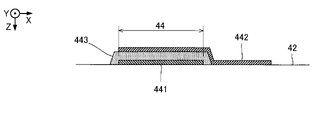
図4に示すように、任意の1個の圧電素子44は、相互に対向する第1電極441と第2電極442との間に圧電体層443を介在させた積層体から成る駆動素子である。第1電極441と第2電極442と圧電体層443とが平面視で重なる部分が圧電素子44として機能する。なお、駆動信号の供給により変形する部分(すなわち振動部42を振動させる能動部)を圧電素子44として画定することも可能である。第1電極441および第2電極442の一方を、複数の圧電素子44に渡って連続する電極(すなわち共通電極)とし、他方を複数の圧電素子44にそれぞれ別々の個別電極とすることが可能である。本実施形態では、第1電極441を共通電極とし、第2電極442を個別電極とする場合を例示する。なお、圧電素子44を駆動する配線構造については後述する。 As shown in FIG. 4, any one piezoelectric element 44 is a driving element composed of a laminated body having a piezoelectric layer 443 interposed between the first electrode 441 and the second electrode 442 facing each other. .. The portion where the first electrode 441, the second electrode 442, and the piezoelectric layer 443 overlap in a plan view functions as the piezoelectric element 44. It is also possible to define the portion deformed by the supply of the drive signal (that is, the active portion that vibrates the vibrating portion 42) as the piezoelectric element 44. It is possible to use one of the first electrode 441 and the second electrode 442 as a continuous electrode (that is, a common electrode) across the plurality of piezoelectric elements 44, and the other as a separate individual electrode for each of the plurality of piezoelectric elements 44. be. In this embodiment, a case where the first electrode 441 is used as a common electrode and the second electrode 442 is used as an individual electrode is illustrated. The wiring structure for driving the piezoelectric element 44 will be described later.

図2および図3に示す第2流路部材48は、複数の圧力室C(さらには複数のノズルN)に供給されるインクを貯留するためのケース部材である。第2流路部材48のうちZ方向の正側の表面が接着剤などで連通板32の表面Faに接合される。第2流路部材48は、第1流路部材30とは別個の材料で形成される。例えば樹脂材料の射出成形で第2流路部材48を製造することが可能である。 The second flow path member 48 shown in FIGS. 2 and 3 is a case member for storing ink supplied to a plurality of pressure chambers C (further, a plurality of nozzles N). The surface of the second flow path member 48 on the positive side in the Z direction is joined to the surface Fa of the communication plate 32 with an adhesive or the like. The second flow path member 48 is made of a material separate from the first flow path member 30. For example, the second flow path member 48 can be manufactured by injection molding of a resin material.

図3に示すように、第1実施形態の第2流路部材48には、第1部分P1および第2部分P2のそれぞれについて、Y方向に長尺な空間Rbと空間Rcとが形成される。空間Rcは空間RbよりもZ方向に長く、空間Rbは空間RcよりもX方向に長い。空間Rcは、空間Rbから連通板32の空間Raまで延出して、空間Rbと空間Raとを連通する。空間Raと空間Rbと空間Rcとで構成される空間は、複数の圧力室Cのインクを循環させるための循環流路であり、複数の圧力室Cにインクを供給する共通液室(リザーバー)として機能する。 As shown in FIG. 3, in the second flow path member 48 of the first embodiment, a long space Rb and a space Rc are formed in the Y direction for each of the first portion P1 and the second portion P2. .. The space Rc is longer in the Z direction than the space Rb, and the space Rb is longer in the X direction than the space Rc. The space Rc extends from the space Rb to the space Ra of the communication plate 32, and communicates the space Rb and the space Ra. The space composed of the space Ra, the space Rb, and the space Rc is a circulation flow path for circulating the ink of the plurality of pressure chambers C, and is a common liquid chamber (reservoir) for supplying the ink to the plurality of pressure chambers C. Functions as.

本実施形態では、第1部分P1側において空間Raと空間Rbと空間Rcとで構成される空間を第1循環流路R1とし、第2部分P2側において空間Raと空間Rbと空間Rcとで構成される空間を第2循環流路R2とする。第1循環流路R1は、第1部分P1側の複数の圧力室Cにインクを供給する流入側の循環流路であり、第2循環流路R2は、第2部分P2側の複数の圧力室Cにインクを供給する流入側の循環流路である。 In the present embodiment, the space composed of the space Ra, the space Rb, and the space Rc on the first portion P1 side is defined as the first circulation flow path R1, and the space Ra, the space Rb, and the space Rc are formed on the second portion P2 side. The formed space is referred to as a second circulation flow path R2. The first circulation flow path R1 is a circulation flow path on the inflow side for supplying ink to a plurality of pressure chambers C on the first portion P1 side, and the second circulation flow path R2 is a plurality of pressures on the second portion P2 side. It is a circulation flow path on the inflow side that supplies ink to the chamber C.

第1循環流路R1は、仮想面OからみてX方向の正側に位置し、第2循環流路R2は、仮想面OからみてX方向の負側に位置する。第2流路部材48のうち連通板32とは反対側の表面には、液体容器14から供給されるインクを第1循環流路R1に導入するための接続口482と、液体容器14から供給されるインクを第2循環流路R2に導入するための接続口482と、が形成される。第1循環流路R1内のインクは、第1部分P1側の供給液室60と各供給路61とを介して、第1部分P1側の圧力室Cに供給される。第2循環流路R2内のインクは、第2部分P2側の供給液室60と各供給路61とを介して、第2部分P2側の圧力室Cに供給される。 The first circulation flow path R1 is located on the positive side in the X direction with respect to the virtual surface O, and the second circulation flow path R2 is located on the negative side in the X direction with respect to the virtual surface O. On the surface of the second flow path member 48 on the side opposite to the communication plate 32, the connection port 482 for introducing the ink supplied from the liquid container 14 into the first circulation flow path R1 and the liquid container 14 supply the ink. A connection port 482 for introducing the ink to be introduced into the second circulation flow path R2 is formed. The ink in the first circulation flow path R1 is supplied to the pressure chamber C on the first portion P1 side via the supply liquid chamber 60 on the first portion P1 side and each supply passage 61. The ink in the second circulation flow path R2 is supplied to the pressure chamber C on the second portion P2 side via the supply liquid chamber 60 on the second portion P2 side and each supply passage 61.

連通板32の表面Fbには、第1部分P1および第2部分P2のそれぞれについて吸振体54が設置される。吸振体54は、可撓性のフィルム(コンプライアンス基板)で構成される。第1部分P1の吸振体54は、第1循環流路R1内のインクの圧力変動を吸収し、第2部分P2の吸振体54は、第2循環流路R2内のインクの圧力変動を吸収する。図3に示すように、第1部分P1の吸振体54は、第1部分P1の連通板32の空間Raと複数の供給路61とを閉塞するように連通板32の表面Fbに設置されて、第1循環流路R1の壁面(具体的には底面)を構成する。第2部分P2の吸振体54は、第2部分P2の連通板32の空間Raと複数の供給路61とを閉塞するように連通板32の表面Fbに設置されて、第2循環流路R2の壁面(具体的には底面)を構成する。 On the surface Fb of the communication plate 32, a vibration absorbing body 54 is installed for each of the first portion P1 and the second portion P2. The vibration absorber 54 is made of a flexible film (compliance substrate). The vibration absorbing body 54 of the first portion P1 absorbs the pressure fluctuation of the ink in the first circulation flow path R1, and the vibration absorbing body 54 of the second portion P2 absorbs the pressure fluctuation of the ink in the second circulation flow path R2. do. As shown in FIG. 3, the vibration absorbing body 54 of the first portion P1 is installed on the surface Fb of the communicating plate 32 so as to block the space Ra of the communicating plate 32 of the first portion P1 and the plurality of supply paths 61. , Constructs a wall surface (specifically, a bottom surface) of the first circulation flow path R1. The vibration absorbing body 54 of the second portion P2 is installed on the surface Fb of the communicating plate 32 so as to block the space Ra of the communicating plate 32 of the second portion P2 and the plurality of supply paths 61, and the second circulation flow path R2. It constitutes the wall surface (specifically, the bottom surface) of.

連通板32のうちノズル板52に対向する表面Fbには循環液室Sが形成される。第1実施形態の循環液室Sは、平面視でY方向に延在する長尺状の有底孔(溝部)である。連通板32の表面Fbに接合されたノズル板52により循環液室Sの開口は閉塞される。循環液室Sは、第1部分P1の圧力室Cと第1循環流路R1との間および第2部分P2と第2循環流路R2との間で、インクを循環させるための循環流路の一部である。循環液室Sは、第1部分P1の圧力室Cと第2部分P2の圧力室Cとからインクを流出する流出側の循環流路として機能する。第2流路部材48のうち連通板32とは反対側の表面に、循環液室Sと連通する接続口482を設け、循環液室Sからのインクを接続口482から導出してもよい。 A circulation liquid chamber S is formed on the surface Fb of the communication plate 32 facing the nozzle plate 52. The circulating liquid chamber S of the first embodiment is a long bottomed hole (groove portion) extending in the Y direction in a plan view. The opening of the circulating fluid chamber S is closed by the nozzle plate 52 joined to the surface Fb of the communication plate 32. The circulating liquid chamber S is a circulation flow path for circulating ink between the pressure chamber C of the first portion P1 and the first circulation flow path R1 and between the second portion P2 and the second circulation flow path R2. Is part of. The circulating liquid chamber S functions as a circulation flow path on the outflow side for ink to flow out from the pressure chamber C of the first portion P1 and the pressure chamber C of the second portion P2. A connection port 482 that communicates with the circulation liquid chamber S may be provided on the surface of the second flow path member 48 on the side opposite to the communication plate 32, and the ink from the circulation liquid chamber S may be led out from the connection port 482.

(循環経路)
次に、本実施形態の循環経路の構成について説明する。図5は、循環経路に着目した液体吐出ヘッド26の構成図である。図5に示すように、循環液室Sは、第1ノズル列L1および第2ノズル列L2に沿って複数のノズルNにわたり連続する。具体的には、第1ノズル列L1のノズルNと第2ノズル列L2のノズルNとの間に循環液室Sが形成される。したがって、図2および図3に示すように、循環液室Sは、第1部分P1の連通路63と第2部分P2の連通路63との間に位置する。このように、第1実施形態の第1流路部材30は、第1部分P1における圧力室C(第1圧力室)および連通路63(第1連通路)と、第2部分P2における圧力室C(第2圧力室)および連通路63(第2連通路)と、第1部分P1の連通路63と第2部分P2の連通路63との間に位置する循環液室Sとが形成された構造体である。本実施形態の第1流路部材30は、循環液室Sと各連通路63との間を仕切る壁状の部分である隔壁部69を含む。
(Circular route)
Next, the configuration of the circulation route of the present embodiment will be described. FIG. 5 is a block diagram of the liquid discharge head 26 focusing on the circulation path. As shown in FIG. 5, the circulating liquid chamber S is continuous over a plurality of nozzles N along the first nozzle row L1 and the second nozzle row L2. Specifically, the circulating liquid chamber S is formed between the nozzle N of the first nozzle row L1 and the nozzle N of the second nozzle row L2. Therefore, as shown in FIGS. 2 and 3, the circulating liquid chamber S is located between the communication passage 63 of the first portion P1 and the communication passage 63 of the second portion P2. As described above, the first flow path member 30 of the first embodiment has the pressure chamber C (first pressure chamber) and the communication passage 63 (first communication passage) in the first portion P1 and the pressure chamber in the second portion P2. C (second pressure chamber) and communication passage 63 (second communication passage), and a circulation liquid chamber S located between the communication passage 63 of the first portion P1 and the communication passage 63 of the second portion P2 are formed. It is a structure. The first flow path member 30 of the present embodiment includes a partition wall portion 69 which is a wall-shaped portion partitioning between the circulating liquid chamber S and each communication passage 63.

なお、上述したように本実施形態では、第1部分P1および第2部分P2のそれぞれにおいて複数の圧力室Cおよび複数の圧電素子44がY方向に配列する。したがって、第1部分P1および第2部分P2のそれぞれにおける複数の圧力室Cまたは複数の圧電素子44にわたり連続するように、循環液室SがY方向に延在する。第1部分P1では、循環液室Sと第1循環流路R1とがX方向に相互に間隔をあけてY方向に延在し、当該X方向の間隔内に第1部分P1の圧力室Cと連通路63とノズルNとが位置している。第2部分P2では、循環液室Sと第2循環流路R2とがX方向に相互に間隔をあけてY方向に延在し、当該X方向の間隔内に第2部分P2の圧力室Cと連通路63とノズルNとが位置している。 As described above, in the present embodiment, the plurality of pressure chambers C and the plurality of piezoelectric elements 44 are arranged in the Y direction in each of the first portion P1 and the second portion P2. Therefore, the circulating fluid chamber S extends in the Y direction so as to be continuous over the plurality of pressure chambers C or the plurality of piezoelectric elements 44 in each of the first portion P1 and the second portion P2. In the first portion P1, the circulating liquid chamber S and the first circulation flow path R1 extend in the Y direction with a mutual interval in the X direction, and the pressure chamber C in the first portion P1 is within the interval in the X direction. And the communication passage 63 and the nozzle N are located. In the second portion P2, the circulating liquid chamber S and the second circulation flow path R2 extend in the Y direction with a mutual spacing in the X direction, and the pressure chamber C in the second portion P2 is within the spacing in the X direction. And the communication passage 63 and the nozzle N are located.

図6は、液体吐出ヘッド26のうち循環液室Sの近傍の部分を拡大した平面図および断面図である。図6に示すように、各ノズルNの中心軸Qaは、連通路63の中心軸Qbからみて循環液室Sとは反対側に位置する。ノズル板52のうち第1流路部材30に対向する表面には、第1部分P1および第2部分P2のそれぞれについて複数の循環連通路72が形成される。第1部分P1の複数の循環連通路72は、第1ノズル列L1の複数のノズルN(または第1ノズル列L1に対応する複数の連通路63)に1対1に対応する。また、第2部分P2の複数の循環連通路72は、第2ノズル列L2の複数のノズルN(または第2ノズル列L2に対応する複数の連通路63)に1対1に対応する。 FIG. 6 is an enlarged plan view and cross-sectional view of a portion of the liquid discharge head 26 in the vicinity of the circulating liquid chamber S. As shown in FIG. 6, the central axis Qa of each nozzle N is located on the opposite side of the circulating liquid chamber S from the central axis Qb of the communication passage 63. On the surface of the nozzle plate 52 facing the first flow path member 30, a plurality of circulation passages 72 are formed for each of the first portion P1 and the second portion P2. The plurality of circulation passages 72 of the first portion P1 have a one-to-one correspondence with the plurality of nozzles N (or the plurality of passages 63 corresponding to the first nozzle row L1) of the first nozzle row L1. Further, the plurality of circulation passages 72 of the second portion P2 correspond one-to-one with the plurality of nozzles N (or the plurality of passages 63 corresponding to the second nozzle row L2) of the second nozzle row L2.

なお、複数のノズルNのそれぞれは、ノズル板52のうち吐出面260から連通板32側の表面まで同径で貫通する貫通孔でもよいが、図6に示すように途中で径が拡径する拡径部Nsを有する貫通孔にしてもよい。図6の拡径部Nsは、ノズル板52のうち連通板32側の表面に開口し、吐出面260に開口するノズルNの開口径よりも大きな径を有する。このように、各ノズルNを、拡径部Nsを有する貫通孔にすることで、各ノズルNの流路抵抗を所望の特性に設定し易くなる。 Each of the plurality of nozzles N may be a through hole penetrating from the discharge surface 260 of the nozzle plate 52 to the surface on the communication plate 32 side with the same diameter, but the diameter increases in the middle as shown in FIG. It may be a through hole having a diameter-expanded portion Ns. The enlarged diameter portion Ns in FIG. 6 has a diameter larger than the opening diameter of the nozzle N that opens to the surface of the nozzle plate 52 on the communication plate 32 side and opens to the discharge surface 260. In this way, by making each nozzle N a through hole having the enlarged diameter portion Ns, it becomes easy to set the flow path resistance of each nozzle N to a desired characteristic.

各循環連通路72は、X方向に延在する溝部(すなわち長尺状の有底孔)であり、インクを流通させる流路として機能する。循環連通路72は、ノズルNから離間した位置(具体的には、その循環連通路72に対応するノズルNからみて循環液室S側)に形成される。例えば、半導体製造技術(例えばドライエッチングやウェットエッチング等の加工技術)により複数のノズルNと複数の循環連通路72とが共通の工程で一括的に形成される。もちろん、循環連通路72をノズル板52に設けずに、連通板32に設けてもよい。 Each circulation passage 72 is a groove portion (that is, a long bottomed hole) extending in the X direction, and functions as a flow path for ink to flow. The circulation communication passage 72 is formed at a position separated from the nozzle N (specifically, on the circulation liquid chamber S side when viewed from the nozzle N corresponding to the circulation communication passage 72). For example, a plurality of nozzles N and a plurality of circulation communication passages 72 are collectively formed by a common process by a semiconductor manufacturing technique (for example, a processing technique such as dry etching or wet etching). Of course, the circulation communication passage 72 may not be provided in the nozzle plate 52 but may be provided in the communication plate 32.

各循環連通路72は、ノズルNの拡径部と同等の流路幅Waで直線状に形成される。また、第1実施形態における循環連通路72の流路幅(Y方向の寸法)Waは、圧力室Cの流路幅(Y方向の寸法)Wbよりも小さい。したがって、循環連通路72の流路幅Waが圧力室Cの流路幅Wbよりも大きい構成と比較して循環連通路72の流路抵抗を大きくすることが可能である。他方、ノズル板52の表面に対する循環連通路72の高さDaは、全長にわたり一定であり、ノズルNの拡径部Nsと同等の高さに形成される。したがって、循環連通路72とノズルNの拡径部Nsとを相異なる深さに形成する構成と比較して、循環連通路72およびノズルNの拡径部を形成し易い。なお、流路の「高さ」とは、Z方向における流路の寸法(例えば流路の形成面と流路の底面との高低差)を意味する。 Each circulation passage 72 is formed linearly with a flow path width Wa equivalent to the enlarged diameter portion of the nozzle N. Further, the flow path width (dimension in the Y direction) Wa of the circulation communication passage 72 in the first embodiment is smaller than the flow path width (dimension in the Y direction) Wb of the pressure chamber C. Therefore, it is possible to increase the flow path resistance of the circulation communication passage 72 as compared with the configuration in which the flow path width Wa of the circulation communication passage 72 is larger than the flow path width Wb of the pressure chamber C. On the other hand, the height Da of the circulation passage 72 with respect to the surface of the nozzle plate 52 is constant over the entire length, and is formed at the same height as the enlarged diameter portion Ns of the nozzle N. Therefore, it is easier to form the diameter-expanded portion of the circulation passage 72 and the nozzle N as compared with the configuration in which the circulation passage 72 and the enlarged diameter portion Ns of the nozzle N are formed at different depths. The "height" of the flow path means the dimension of the flow path in the Z direction (for example, the height difference between the formation surface of the flow path and the bottom surface of the flow path).

第1部分P1における任意の1個の循環連通路72は、第1ノズル列L1のうちその任意の1個の循環連通路72に対応するノズルNからみて循環液室S側に位置する。また、第2部分P2における任意の1個の循環連通路72は、第2ノズル列L2のうちその任意の1個の循環連通路72に対応するノズルNからみて循環液室S側に位置する。そして、各循環連通路72のうち仮想面Oとは反対側である連通路63側の端部は、その循環連通路72に対応する1個の連通路63に平面視で重なる。すなわち、循環連通路72は連通路63に連通する。他方、各循環連通路72のうち仮想面O側である循環液室S側の端部は循環液室Sに平面視で重なる。すなわち、循環連通路72は循環液室Sに連通する。以上の説明に示すように、複数の連通路63のそれぞれが循環連通路72を介して循環液室Sに連通する。したがって、図6に破線の矢印で示すように、各連通路63内のインクは循環連通路72を介して循環液室Sに供給される。すなわち、第1実施形態では、第1ノズル列L1に対応する複数の連通路63と第2ノズル列L2に対応する複数の連通路63とが1個の循環液室Sに対して共通に連通する。 The arbitrary one circulating communication passage 72 in the first portion P1 is located on the circulating liquid chamber S side with respect to the nozzle N corresponding to the arbitrary one circulating communication passage 72 in the first nozzle row L1. Further, any one circulation communication passage 72 in the second portion P2 is located on the circulation liquid chamber S side with respect to the nozzle N corresponding to the arbitrary one circulation communication passage 72 in the second nozzle row L2. .. The end of each circulation passage 72 on the side of the communication passage 63 opposite to the virtual surface O overlaps with one communication passage 63 corresponding to the circulation passage 72 in a plan view. That is, the circulation communication passage 72 communicates with the communication passage 63. On the other hand, the end of each circulation passage 72 on the circulation liquid chamber S side, which is the virtual surface O side, overlaps the circulation liquid chamber S in a plan view. That is, the circulation communication passage 72 communicates with the circulation liquid chamber S. As shown in the above description, each of the plurality of communication passages 63 communicates with the circulation liquid chamber S via the circulation communication passage 72. Therefore, as shown by the broken line arrow in FIG. 6, the ink in each communication passage 63 is supplied to the circulation liquid chamber S via the circulation passage 72. That is, in the first embodiment, the plurality of communication passages 63 corresponding to the first nozzle row L1 and the plurality of communication passages 63 corresponding to the second nozzle row L2 are commonly communicated with one circulating liquid chamber S. do.

このように本実施形態の圧力室Cは、連通路63と循環連通路72とを介して間接的に循環液室Sに連通する。この構成によれば、圧電素子44の動作により圧力室C内の圧力が変動すると、連通路63内を流動するインクのうちの一部がノズルNから外部に吐出され、残りの一部が連通路63から循環連通路72を経由して循環液室Sに流入する。本実施形態では、例えば圧電素子44の1回の駆動により連通路63を流通するインクのうち、ノズルNを介して吐出されるインクの量(以下「吐出量」という)が、連通路63を流通するインクのうち循環連通路72を介して循環液室Sに流入するインクの量(以下「循環量」という)を上回るように、連通路63とノズルと循環連通路72とのイナータンスが選定される。 As described above, the pressure chamber C of the present embodiment indirectly communicates with the circulating liquid chamber S via the communication passage 63 and the circulation communication passage 72. According to this configuration, when the pressure in the pressure chamber C fluctuates due to the operation of the piezoelectric element 44, a part of the ink flowing in the communication passage 63 is discharged from the nozzle N to the outside, and the remaining part is connected. It flows into the circulating liquid chamber S from the passage 63 via the circulating communication passage 72. In the present embodiment, for example, of the ink flowing through the communication passage 63 by one drive of the piezoelectric element 44, the amount of ink discharged through the nozzle N (hereinafter referred to as “ejection amount”) determines the communication passage 63. The inertia of the communication passage 63, the nozzle, and the circulation communication passage 72 is selected so as to exceed the amount of ink flowing into the circulating liquid chamber S through the circulation communication passage 72 (hereinafter referred to as “circulation amount”) among the circulating inks. Will be done.

図5に示す循環機構75は、循環液室S内のインクを第1循環流路R1および第2循環流路R2に供給(すなわち循環)するための機構である。循環機構75は、例えば循環液室Sからインクを吸引する吸引機構(例えばポンプ)と、インクに混在する気泡や異物を捕集するフィルター機構と、インクの加熱により増粘を低減する加温機構とを具備する(図示略)。循環機構75により気泡や異物が除去されるとともに増粘が低減されたインクが、循環機構75から2つの接続口482を介して第1循環流路R1と第2循環流路R2とのそれぞれに供給される。したがって、第1実施形態の第1部分P1側では、第1循環流路R1→供給路61→圧力室C→連通路63→循環連通路72→循環液室S→循環機構75→第1循環流路R1という経路でインクが循環する。また、第2部分P2側では、第2循環流路R2→供給路61→圧力室C→連通路63→循環連通路72→循環液室S→循環機構75→第2循環流路R2という経路でインクが循環する。 The circulation mechanism 75 shown in FIG. 5 is a mechanism for supplying (that is, circulating) the ink in the circulation liquid chamber S to the first circulation flow path R1 and the second circulation flow path R2. The circulation mechanism 75 includes, for example, a suction mechanism (for example, a pump) that sucks ink from the circulating liquid chamber S, a filter mechanism that collects air bubbles and foreign substances mixed in the ink, and a heating mechanism that reduces thickening by heating the ink. (Not shown). Ink from which air bubbles and foreign substances are removed by the circulation mechanism 75 and whose thickening is reduced is sent from the circulation mechanism 75 to the first circulation flow path R1 and the second circulation flow path R2 via two connection ports 482, respectively. Will be supplied. Therefore, on the first portion P1 side of the first embodiment, the first circulation flow path R1 → the supply path 61 → the pressure chamber C → the communication passage 63 → the circulation communication passage 72 → the circulation liquid chamber S → the circulation mechanism 75 → the first circulation. Ink circulates in a path called the flow path R1. Further, on the second portion P2 side, a route of second circulation flow path R2 → supply path 61 → pressure chamber C → communication passage 63 → circulation communication passage 72 → circulation liquid chamber S → circulation mechanism 75 → second circulation flow path R2. Ink circulates in.

循環機構75は、Y方向における循環液室Sの両側からインクを吸引する。循環液室Sには、Y方向の正側の端部の近傍に位置する循環口Staと、Y方向の負側の端部の近傍に位置する循環口Stbとが形成される。循環機構75は、循環口Staおよび循環口Stbの双方からインクを吸引する。なお、Y方向における循環液室Sの一方の端部のみからインクを吸引する構成では、循環液室Sの両端部間でインクの圧力に差異が発生し、循環液室S内の圧力差に起因して連通路63内のインクの圧力がY方向の位置に応じて相違し得る。したがって、各ノズルNからのインクの吐出特性(例えば吐出量や吐出速度)がY方向の位置に応じて相違する可能性がある。以上の構成とは対照的に、第1実施形態では、循環液室Sの両側(循環口Staおよび循環口Stb)からインクが吸引されるから、循環液室Sの内部における圧力差が低減される。したがって、Y方向に配列する複数のノズルNにわたりインクの吐出特性を高精度に近似させることが可能である。ただし、循環液室S内でのY方向における圧力差が特段の問題とならない場合には、循環液室Sの一方の端部からインクを吸引するように構成してもよい。 The circulation mechanism 75 sucks ink from both sides of the circulation liquid chamber S in the Y direction. In the circulating liquid chamber S, a circulation port Sta located near the end on the positive side in the Y direction and a circulation port Stb located near the end on the negative side in the Y direction are formed. The circulation mechanism 75 sucks ink from both the circulation port Sta and the circulation port Stb. In the configuration in which ink is sucked from only one end of the circulating liquid chamber S in the Y direction, a difference in ink pressure occurs between both ends of the circulating liquid chamber S, and the pressure difference in the circulating liquid chamber S becomes Therefore, the pressure of the ink in the communication passage 63 may differ depending on the position in the Y direction. Therefore, the ejection characteristics of the ink from each nozzle N (for example, the ejection amount and the ejection speed) may differ depending on the position in the Y direction. In contrast to the above configuration, in the first embodiment, since the ink is sucked from both sides (circulation port Sta and circulation port Stb) of the circulation liquid chamber S, the pressure difference inside the circulation liquid chamber S is reduced. To. Therefore, it is possible to approximate the ink ejection characteristics with high accuracy over a plurality of nozzles N arranged in the Y direction. However, if the pressure difference in the Y direction in the circulating liquid chamber S does not pose a particular problem, the ink may be sucked from one end of the circulating liquid chamber S.

また、循環連通路72と連通路63とは平面視で重なり、連通路63と圧力室Cとは平面視で重なるから、循環連通路72と圧力室Cとは平面視で相互に重なる。他方、循環液室Sと圧力室Cとは平面視で相互に重ならない。また、圧電素子44は、X方向に沿って圧力室Cの全体にわたり形成されるから、循環連通路72と圧電素子44とは平面視で相互に重なる一方、循環液室Sと圧電素子44とは平面視で相互に重ならない。以上の構成によれば、圧力室Cまたは圧電素子44は、循環連通路72に平面視で重なる一方、循環液室Sには平面視で重ならないから、例えば圧力室Cまたは圧電素子44が循環連通路72に平面視で重ならない構成と比較して、液体吐出ヘッド26を小型化し易い。もちろん、圧力室Cや圧電素子44が循環液室Sには平面視で重なってもよい。 Further, since the circulation passage 72 and the communication passage 63 overlap in a plan view and the communication passage 63 and the pressure chamber C overlap in a plane view, the circulation communication passage 72 and the pressure chamber C overlap each other in a plane view. On the other hand, the circulating fluid chamber S and the pressure chamber C do not overlap each other in a plan view. Further, since the piezoelectric element 44 is formed over the entire pressure chamber C along the X direction, the circulation communication passage 72 and the piezoelectric element 44 overlap each other in a plan view, while the circulating liquid chamber S and the piezoelectric element 44 Do not overlap each other in plan view. According to the above configuration, the pressure chamber C or the piezoelectric element 44 overlaps the circulation communication passage 72 in a plan view, while the pressure chamber C or the piezoelectric element 44 does not overlap in a plan view. Therefore, for example, the pressure chamber C or the piezoelectric element 44 circulates. The liquid discharge head 26 can be easily miniaturized as compared with a configuration in which the communication passage 72 does not overlap in a plan view. Of course, the pressure chamber C and the piezoelectric element 44 may overlap the circulating liquid chamber S in a plan view.

また、連通路63と循環液室Sとを連通させる循環連通路72がノズル板52に形成されるから、循環連通路が連通板32に形成される場合と比較して、ノズルNの近傍のインクを効率的に循環液室Sに循環させることが可能である。また、第1実施形態では、第1ノズル列L1に対応する連通路63と第2ノズル列L2に対応する連通路63とが両者間の循環液室Sに共通に連通する。したがって、第1ノズル列L1に対応する各循環連通路72が連通する循環液室Sと第2ノズル列L2に対応する各循環連通路72が連通する循環液室とを別個に設けた構成と比較して、液体吐出ヘッド26の構成を簡素化できるので、液体吐出ヘッド26を小型化できる。 Further, since the circulation communication passage 72 that communicates the communication passage 63 and the circulation liquid chamber S is formed in the nozzle plate 52, the vicinity of the nozzle N is closer than that in the case where the circulation communication passage is formed in the communication plate 32. It is possible to efficiently circulate the ink in the circulating liquid chamber S. Further, in the first embodiment, the communication passage 63 corresponding to the first nozzle row L1 and the communication passage 63 corresponding to the second nozzle row L2 communicate in common with the circulating liquid chamber S between them. Therefore, the circulation liquid chamber S through which each circulation communication passage 72 corresponding to the first nozzle row L1 communicates and the circulation liquid chamber through which each circulation communication passage 72 corresponding to the second nozzle row L2 communicates are separately provided. In comparison, the configuration of the liquid discharge head 26 can be simplified, so that the liquid discharge head 26 can be miniaturized.

(配線基板)
図3に示す配線基板45は、第1流路部材30に積層される保護基板46および駆動IC47によって構成される。本実施形態の配線基板45は、保護基板46に駆動IC47を設置し、駆動IC47と圧電素子44との間の配線を保護基板46に設ける場合を例示する。保護基板46は、複数の圧電素子44を保護するための板状部材である。本実施形態の保護基板46は、振動部42の表面Fcに設置される。なお、保護基板46は、圧力室基板34の表面に設置されるようにしてもよい。第2流路部材48のうちZ方向の正側の表面にはY方向に延在する溝状の凹部484が形成され、圧力室基板34と振動部42と配線基板45とはその凹部484の内側に収容される。平面視で凹部484が第1領域Aに重なるように第1流路部材30と第2流路部材48とが積層されることで、凹部484のZ方向の負側の開口は第1流路部材30で閉じられる。凹部484は大気開放されていてもよい。こうして本実施形態の凹部484は、配線基板45を収容するための収容空間Gとして機能する。このように、収容空間Gは、第1流路部材30と第2流路部材48との間に、平面視で第1領域Aに重なるように形成される。
(Wiring board)
The wiring board 45 shown in FIG. 3 is composed of a protective board 46 and a drive IC 47 laminated on the first flow path member 30. The wiring board 45 of the present embodiment illustrates a case where the drive IC 47 is installed on the protective substrate 46 and the wiring between the drive IC 47 and the piezoelectric element 44 is provided on the protective substrate 46. The protective substrate 46 is a plate-shaped member for protecting the plurality of piezoelectric elements 44. The protective substrate 46 of this embodiment is installed on the surface Fc of the vibrating portion 42. The protective substrate 46 may be installed on the surface of the pressure chamber substrate 34. A groove-shaped recess 484 extending in the Y direction is formed on the surface of the second flow path member 48 on the positive side in the Z direction, and the pressure chamber substrate 34, the vibrating portion 42, and the wiring board 45 are formed in the recess 484. It is housed inside. By stacking the first flow path member 30 and the second flow path member 48 so that the recess 484 overlaps the first region A in a plan view, the opening on the negative side of the recess 484 in the Z direction is the first flow path. It is closed by the member 30. The recess 484 may be open to the atmosphere. In this way, the recess 484 of the present embodiment functions as an accommodation space G for accommodating the wiring board 45. In this way, the accommodation space G is formed between the first flow path member 30 and the second flow path member 48 so as to overlap the first region A in a plan view.

保護基板46の材料や製法は任意であるが、連通板32や圧力室基板34と同様に、例えばSiの単結晶基板を半導体製造技術により加工することで保護基板46を形成することができる。保護基板46のうち振動部42側の表面に形成された凹部に複数の圧電素子44が収容される。この保護基板46の凹部と振動部42とで囲まれた空間は、圧電素子44の設置空間462を構成する。保護基板46は、圧電素子44の設置空間462を封止することによって、湿気や外部からの衝撃などから圧電素子44を保護することができる。 The material and manufacturing method of the protective substrate 46 are arbitrary, but the protective substrate 46 can be formed by processing, for example, a Si single crystal substrate by a semiconductor manufacturing technique, similarly to the communication plate 32 and the pressure chamber substrate 34. A plurality of piezoelectric elements 44 are housed in a recess formed on the surface of the protective substrate 46 on the vibrating portion 42 side. The space surrounded by the recess of the protective substrate 46 and the vibrating portion 42 constitutes the installation space 462 of the piezoelectric element 44. The protective substrate 46 can protect the piezoelectric element 44 from moisture, external impact, and the like by sealing the installation space 462 of the piezoelectric element 44.

駆動IC47は、保護基板46のうち振動部42側とは反対側の表面(実装面)に実装される。駆動IC47は、複数の圧電素子44を駆動するための駆動回路を備えた略矩形状のICチップである。駆動IC47は、制御ユニット20による制御のもとで圧電素子44の駆動信号を生成および供給することで各圧電素子44を駆動する。液体吐出ヘッド26の少なくとも一部の圧電素子44は平面視で駆動IC47に重なる。図4に示すように、本実施形態の保護基板46には、駆動IC47と各圧電素子44とを電気的に接続するための複数の接続端子464および配線466が設けられている。 The drive IC 47 is mounted on the surface (mounting surface) of the protective substrate 46 opposite to the vibrating portion 42 side. The drive IC 47 is a substantially rectangular IC chip provided with a drive circuit for driving a plurality of piezoelectric elements 44. The drive IC 47 drives each piezoelectric element 44 by generating and supplying a drive signal of the piezoelectric element 44 under the control of the control unit 20. At least a part of the piezoelectric element 44 of the liquid discharge head 26 overlaps the drive IC 47 in a plan view. As shown in FIG. 4, the protective substrate 46 of the present embodiment is provided with a plurality of connection terminals 464 and wiring 466 for electrically connecting the drive IC 47 and each piezoelectric element 44.

(圧電素子を駆動するための配線構造)
ここで、圧電素子44を駆動するための液体吐出ヘッド26の配線構造について説明する。図7および図8は、本実施形態の圧電素子44を駆動するための配線構造についての説明図である。図7は、振動部42および圧電素子44をZ方向(上方)から見た平面図である。図8は、保護基板46をZ方向(上方)から見た平面図である。本実施形態では、第1圧電素子と第2圧電素子を備える。図7において仮想面Oから見てX方向の一方側(例えば第1部分P1側)に配列される複数の圧電素子44が第1圧電素子に相当し、仮想面Oから見てX方向の他方側(例えば第2部分P2側)に配列される複数の圧電素子44が第2圧電素子に相当する。
(Wiring structure for driving the piezoelectric element)
Here, the wiring structure of the liquid discharge head 26 for driving the piezoelectric element 44 will be described. 7 and 8 are explanatory views of a wiring structure for driving the piezoelectric element 44 of the present embodiment. FIG. 7 is a plan view of the vibrating portion 42 and the piezoelectric element 44 as viewed from the Z direction (upper side). FIG. 8 is a plan view of the protective substrate 46 as viewed from the Z direction (upper side). In this embodiment, a first piezoelectric element and a second piezoelectric element are provided. In FIG. 7, a plurality of piezoelectric elements 44 arranged on one side in the X direction (for example, the first portion P1 side) when viewed from the virtual surface O correspond to the first piezoelectric element, and the other in the X direction when viewed from the virtual surface O. A plurality of piezoelectric elements 44 arranged on the side (for example, the second portion P2 side) correspond to the second piezoelectric element.

図3および図8に示すように、保護基板46に形成される配線466は、第1配線466aと第2配線466bに分けられる。接続端子464は、第1配線466aに電気的に接続される第1接続端子464aと、第2配線466bに電気的に接続される第2接続端子464bとに分けられる。第1配線466aは、駆動IC47のベース電圧VBSの出力端子に接続される配線であり、圧電素子44の配置に沿ってY方向に連続して形成される。具体的には、第1配線466aは、保護基板46をZ方向に貫通する貫通孔に金属が埋め込まれて成る複数の貫通配線と、保護基板46内においてY方向に延在して上記複数の貫通配線に接続される接続配線とからなる。なお、第1配線466aは、貫通配線と接続配線とによる構成に限られない。 As shown in FIGS. 3 and 8, the wiring 466 formed on the protective substrate 46 is divided into a first wiring 466a and a second wiring 466b. The connection terminal 464 is divided into a first connection terminal 464a electrically connected to the first wiring 466a and a second connection terminal 464b electrically connected to the second wiring 466b. The first wiring 466a is a wiring connected to the output terminal of the base voltage VBS of the drive IC 47, and is continuously formed in the Y direction along the arrangement of the piezoelectric element 44. Specifically, the first wiring 466a includes a plurality of through wirings in which a metal is embedded in a through hole penetrating the protective substrate 46 in the Z direction, and the plurality of wirings extending in the Y direction in the protective substrate 46. It consists of a connection wiring connected to a through wiring. The first wiring 466a is not limited to the configuration of the through wiring and the connecting wiring.

第2配線466bは、駆動IC47の駆動電圧COM(駆動信号)の出力端子に接続される配線であり、複数の圧電素子44のそれぞれに1つずつ対応して形成される。具体的には、第1圧電素子を構成する複数の圧電素子44に対応する複数の第2配線466bと、第2圧電素子を構成する複数の圧電素子44に対応する複数の第2配線466bとがそれぞれ、Y方向に沿って配列される。各第2配線466bは、保護基板46をZ方向に貫通する貫通孔に金属を埋め込んで成る貫通配線と、保護基板46のX方向に延びて貫通配線を駆動IC47の端子(図示略)に接続する接続配線とからなる。なお、第2配線466bは、貫通配線と接続配線とによる構成に限られない。 The second wiring 466b is a wiring connected to the output terminal of the drive voltage COM (drive signal) of the drive IC 47, and is formed corresponding to each of the plurality of piezoelectric elements 44 one by one. Specifically, a plurality of second wirings 466b corresponding to the plurality of piezoelectric elements 44 constituting the first piezoelectric element, and a plurality of second wirings 466b corresponding to the plurality of piezoelectric elements 44 constituting the second piezoelectric element. Are arranged along the Y direction, respectively. Each second wiring 466b connects a through wiring formed by embedding metal in a through hole penetrating the protection board 46 in the Z direction and a through wiring extending in the X direction of the protection board 46 to a terminal (not shown) of the drive IC 47. It consists of connection wiring. The second wiring 466b is not limited to the configuration of the through wiring and the connecting wiring.

第1接続端子464aは、各圧電素子44の共通電極である第1電極441の端子441tと第1配線466aとを接続する。これにより、各圧電素子44の第1電極441は、第1接続端子464aと第1配線466aとを介して駆動IC47のベース電圧VBSの出力端子に接続される。したがって、駆動IC47の出力端子から出力されたベース電圧VBSは、第1配線466aと第1接続端子464aとを介して、各圧電素子44の第1電極441に印加される。 The first connection terminal 464a connects the terminal 441t of the first electrode 441, which is a common electrode of each piezoelectric element 44, with the first wiring 466a. As a result, the first electrode 441 of each piezoelectric element 44 is connected to the output terminal of the base voltage VBS of the drive IC 47 via the first connection terminal 464a and the first wiring 466a. Therefore, the base voltage VBS output from the output terminal of the drive IC 47 is applied to the first electrode 441 of each piezoelectric element 44 via the first wiring 466a and the first connection terminal 464a.

第2接続端子464bは、各圧電素子44の個別電極である第2電極442の端子442tと第2配線466bとを接続する。これにより、各圧電素子44の第2電極442は、第2接続端子464bと第2配線466bとを介して駆動IC47の駆動電圧COMの出力端子に接続される。したがって、駆動IC47の出力端子から出力された駆動電圧COMは、第2接続端子464bと第2配線466bとを介して各圧電素子44の第2電極442に印加される。 The second connection terminal 464b connects the terminal 442t of the second electrode 442, which is an individual electrode of each piezoelectric element 44, with the second wiring 466b. As a result, the second electrode 442 of each piezoelectric element 44 is connected to the output terminal of the drive voltage COM of the drive IC 47 via the second connection terminal 464b and the second wiring 466b. Therefore, the drive voltage COM output from the output terminal of the drive IC 47 is applied to the second electrode 442 of each piezoelectric element 44 via the second connection terminal 464b and the second wiring 466b.

図3に示すように、第1接続端子464a、第2接続端子464bはそれぞれ、例えば樹脂材料で形成された突起を導電材料で被覆した樹脂コアバンプで構成される。ただし、第1接続端子464a、第2接続端子464bはそれぞれ、樹脂コアバンプに限られず、例えば金属バンプで構成してもよい。なお、駆動IC47の端子と各第1配線466aとの間や駆動IC47の端子と各第2配線466bとの間も、第1接続端子464aと第2接続端子464bと同様の樹脂コアバンプで接続するようにしてもよく、金属バンプで接続してもよい。 As shown in FIG. 3, each of the first connection terminal 464a and the second connection terminal 464b is composed of, for example, a resin core bump in which a protrusion formed of a resin material is coated with a conductive material. However, the first connection terminal 464a and the second connection terminal 464b are not limited to the resin core bumps, and may be formed of, for example, metal bumps. The terminals of the drive IC 47 and each of the first wirings 466a and the terminals of the drive IC 47 and each of the second wirings 466b are also connected by the same resin core bumps as the first connection terminal 464a and the second connection terminal 464b. It may be connected with a metal bump.

図7および図8に示すように、第1圧電素子を構成する複数の圧電素子44のうち任意の1個の圧電素子44の第2電極442の端子442tは、第1部分P1側の複数の接続端子464のうちその任意の1個の圧電素子44に対応する1個の第2接続端子464bに接続される。第2圧電素子を構成する複数の圧電素子44のうち任意の1個の圧電素子44の第2電極442の端子442tは、第2部分P2側の複数の接続端子464のうちその任意の1個の圧電素子44に対応する1個の第2接続端子464bに接続される。また、第1電極441の端子441tのうち任意の1個の端子441tは、その任意の1個の端子441tに対応する1個の第1接続端子464aに接続される。なお、第1接続端子464aの数は、第2接続端子464bの数よりも少ない。第1接続端子464aの数は、1つでもよいが、複数の第1接続端子464aをY方向に配置することで、Y方向に配列される各圧電素子44のベース電圧VBSを安定させることができる。 As shown in FIGS. 7 and 8, the terminals 442t of the second electrode 442 of any one of the plurality of piezoelectric elements 44 constituting the first piezoelectric element 44 have a plurality of terminals 442t on the first portion P1 side. It is connected to one second connection terminal 464b corresponding to any one piezoelectric element 44 of the connection terminals 464. The terminal 442t of the second electrode 442 of any one of the plurality of piezoelectric elements 44 constituting the second piezoelectric element is any one of the plurality of connection terminals 464 on the second portion P2 side. It is connected to one second connection terminal 464b corresponding to the piezoelectric element 44 of the above. Further, any one terminal 441t of the terminals 441t of the first electrode 441 is connected to one first connection terminal 464a corresponding to the arbitrary one terminal 441t. The number of first connection terminals 464a is smaller than the number of second connection terminals 464b. The number of the first connection terminals 464a may be one, but by arranging a plurality of first connection terminals 464a in the Y direction, the base voltage VBS of each piezoelectric element 44 arranged in the Y direction can be stabilized. can.

図2に示すように、保護基板46には、駆動IC47の入力端子に接続される駆動電圧COMとベース電圧VBSの配線を含む複数の配線468が形成される。複数の配線468は、保護基板46の実装面のうちY方向(すなわち複数の圧電素子44が配列する方向)の端部に位置する領域Eまで延在する。領域Eには配線部材29が接合される。配線部材29は、制御ユニット20と駆動IC47とを電気的に接続する複数の配線(図示略)が形成された実装部品である。例えばFPC(Flexible Printed Circuit)やFFC(Flexible Flat Cable)等の可撓性基板が配線部材29として好適に採用される。上述したように、本実施形態の保護基板46は、駆動信号を伝送する配線466、468などが形成された基板としても機能する。ただし、駆動IC47の実装や配線の形成に使用される基板を保護基板46とは別個に設置することも可能である。 As shown in FIG. 2, a plurality of wirings 468 including wirings of the driving voltage COM and the base voltage VBS connected to the input terminals of the driving IC 47 are formed on the protective substrate 46. The plurality of wirings 468 extend to the region E located at the end of the mounting surface of the protective substrate 46 in the Y direction (that is, the direction in which the plurality of piezoelectric elements 44 are arranged). The wiring member 29 is joined to the region E. The wiring member 29 is a mounting component on which a plurality of wirings (not shown) for electrically connecting the control unit 20 and the drive IC 47 are formed. For example, a flexible substrate such as an FPC (Flexible Printed Circuit) or an FFC (Flexible Flat Cable) is suitably adopted as the wiring member 29. As described above, the protective substrate 46 of the present embodiment also functions as a substrate on which wirings 466, 468 and the like for transmitting drive signals are formed. However, it is also possible to install the substrate used for mounting the drive IC 47 and forming the wiring separately from the protective substrate 46.

図9は、第1実施形態の液体吐出ヘッド26において、インクの流れを示す作用説明図である。図9は、液体吐出ヘッド26の断面図であり、図3に対応する。第1実施形態の液体吐出ヘッド26によれば、図9の矢印に示すような循環するインクの流れを形成できる。具体的には、第1部分P1側では、第1循環流路R1→供給路61→圧力室C→連通路63→循環連通路72→循環液室S→循環機構75→第1循環流路R1という経路で循環するインクの流れを形成できる。第2部分P2側では、第2循環流路R2→供給路61→圧力室C→連通路63→循環連通路72→循環液室S→循環機構75→第2循環流路R2という経路で循環するインクの流れを形成できる。 FIG. 9 is an operation explanatory view showing the flow of ink in the liquid ejection head 26 of the first embodiment. FIG. 9 is a cross-sectional view of the liquid discharge head 26 and corresponds to FIG. According to the liquid ejection head 26 of the first embodiment, it is possible to form a circulating ink flow as shown by the arrow in FIG. Specifically, on the first portion P1 side, the first circulation flow path R1 → supply path 61 → pressure chamber C → communication passage 63 → circulation communication passage 72 → circulation liquid chamber S → circulation mechanism 75 → first circulation flow path. It is possible to form a flow of ink that circulates along the path of R1. On the second portion P2 side, circulation is carried out in the order of second circulation flow path R2 → supply path 61 → pressure chamber C → communication passage 63 → circulation communication passage 72 → circulation liquid chamber S → circulation mechanism 75 → second circulation flow path R2. Ink flow can be formed.

第1実施形態の液体吐出ヘッド26では、圧電素子44の1回の駆動により連通路63を流通するインクのうちノズルNを介して吐出されるインクの吐出量が、連通路63を流通するインクのうち循環連通路72を介して循環液室Sに流入するインクの循環量を上回るように、連通路63とノズルNと循環連通路72とのイナータンスが選定される。 In the liquid ejection head 26 of the first embodiment, the amount of ink ejected through the nozzle N among the inks circulating in the communication passage 63 by one drive of the piezoelectric element 44 is the ink flowing through the communication passage 63. Of these, the inertia between the communication passage 63, the nozzle N, and the circulation communication passage 72 is selected so as to exceed the circulation amount of the ink flowing into the circulation liquid chamber S through the circulation communication passage 72.

具体的には例えば、圧力室C内から連通路63を流通するインクのうち循環量の比率が70%以上となる(吐出量の比率が30%以下)となるように、連通路63とノズルNと循環連通路72との各々の流路抵抗が決定される。以上の構成によれば、インクの吐出量を確保しながら、ノズルNの近傍のインクを効果的に循環液室Sに循環させることが可能である。なお、上述したインクの吐出量と循環量との比率は70%に限られず、循環連通路72の流路抵抗によって調整できる。循環連通路72の流路抵抗を大きくするほど、循環量を減少させて吐出量を増加させることができ、循環連通路72の流路抵抗を小さいほど、循環量を増加させて吐出量を減少させることができる。 Specifically, for example, the communication passage 63 and the nozzle so that the circulation amount ratio of the ink flowing through the communication passage 63 from the pressure chamber C is 70% or more (the ejection amount ratio is 30% or less). The flow path resistance of N and the circulation communication passage 72 is determined. According to the above configuration, it is possible to effectively circulate the ink in the vicinity of the nozzle N to the circulating liquid chamber S while ensuring the ink ejection amount. The ratio of the ink ejection amount to the circulation amount described above is not limited to 70%, and can be adjusted by the flow path resistance of the circulation communication passage 72. The larger the flow path resistance of the circulation passage 72, the smaller the circulation amount and the larger the discharge amount, and the smaller the flow path resistance of the circulation communication passage 72, the larger the circulation amount and the lower the discharge amount. Can be made to.

以上説明したとおり、第1実施形態の構成の液体吐出ヘッド26では、Z方向に互いに重なるように第1流路部材30に第2流路部材48が積層される。図3に示すように、第1流路部材30の表面は、配線基板45を介して第2流路部材48に積層される第1領域Aと、配線基板45を介さずに第2流路部材48に積層される第2領域Bとを含む。第1流路部材30の表面は、第1流路部材30のうちZ方向の負側の表面である。本実施形態の第1流路部材30のうちZ方向の負側の表面には、連通板32に圧力室基板34と振動部42とが積層されている領域と積層されていない領域がある。したがって、本実施形態の第1流路部材30の表面とは、連通板32に圧力室基板34と振動部42とが積層されていない領域では連通板32の表面Faであり、連通板32に圧力室基板34と振動部42とが積層されている領域では振動部42の表面Fc(圧力室基板34の表面のうち振動部42が積層されていない部分は、その部分の圧力室基板34の表面も含む)である。 As described above, in the liquid discharge head 26 having the configuration of the first embodiment, the second flow path member 48 is laminated on the first flow path member 30 so as to overlap each other in the Z direction. As shown in FIG. 3, the surface of the first flow path member 30 has a first region A laminated on the second flow path member 48 via the wiring board 45 and a second flow path without passing through the wiring board 45. The second region B laminated on the member 48 is included. The surface of the first flow path member 30 is the surface on the negative side in the Z direction of the first flow path member 30. On the surface of the first flow path member 30 of the present embodiment on the negative side in the Z direction, there is a region where the pressure chamber substrate 34 and the vibrating portion 42 are laminated on the communication plate 32 and a region where the communication plate 32 is not laminated. Therefore, the surface of the first flow path member 30 of the present embodiment is the surface Fa of the communication plate 32 in the region where the pressure chamber substrate 34 and the vibrating portion 42 are not laminated on the communication plate 32, and the communication plate 32 has a surface. In the region where the pressure chamber substrate 34 and the vibrating portion 42 are laminated, the surface Fc of the vibrating portion 42 (the portion of the surface of the pressure chamber substrate 34 where the vibrating portion 42 is not laminated is the pressure chamber substrate 34 in that portion. (Including the surface).

図3に示すように、本実施形態の第1領域Aは、平面視で収容空間Gに重なる領域であり、振動部42の表面Fcだけでなく、連通板32の表面Faの一部も含んでいる。このように、第1領域Aは、連通板32の表面Faの一部を含むようにしてもよい。本実施形態の第2領域Bは、連通板32の表面Faを含み、振動部42の表面Fcを含んでいない。なお、図3に示す第1流路部材30の表面には、第1部分P1と第2部分P2にわたる第1領域Aと、第1部分P1と第2部分P2とのそれぞれの第2領域Bがある。 As shown in FIG. 3, the first region A of the present embodiment is a region overlapping the accommodation space G in a plan view, and includes not only the surface Fc of the vibrating portion 42 but also a part of the surface Fa of the communication plate 32. I'm out. As described above, the first region A may include a part of the surface Fa of the communication plate 32. The second region B of the present embodiment includes the surface Fa of the communication plate 32 and does not include the surface Fc of the vibrating portion 42. On the surface of the first flow path member 30 shown in FIG. 3, a first region A extending over the first portion P1 and the second portion P2, and a second region B of the first portion P1 and the second portion P2, respectively. There is.

第2流路部材48の表面は、Z方向において第1領域Aと第2領域Bとに重なるように第1流路部材30の表面(第1実施形態では連通板32の表面Faのうち第2領域B)に例えば接着剤などで接合される。配線基板45は、第1領域Aにおいて第1流路部材30に形成される収容空間Gに設置される。第1循環流路R1は、第1部分P1の第2領域Bにおいて第1流路部材30に形成される第1流路となる空間Raと、第2流路部材48に形成される第2流路となる空間Rcとが連通して形成される。第2循環流路R2は、第2部分P2の第2領域Bにおいて第1流路部材30に形成される第1流路となる空間Raと、第2流路部材48に形成される第2流路となる空間Rcとが連通して形成される。なお、第1領域Aと第2領域Bとは、X-Y平面の面内方向に沿う方向に並んでいるので、第1領域Aの配線基板と第2領域Bの循環流路R1、R2とは、X-Y平面の面内方向に沿う方向に重なるように配置できる。 The surface of the second flow path member 48 is the surface of the first flow path member 30 so as to overlap the first region A and the second region B in the Z direction (in the first embodiment, the surface Fa of the communication plate 32 is the first. It is joined to the two regions B) with, for example, an adhesive. The wiring board 45 is installed in the accommodation space G formed in the first flow path member 30 in the first region A. The first circulation flow path R1 is a space Ra that is a first flow path formed in the first flow path member 30 in the second region B of the first portion P1 and a second flow path member 48. It is formed by communicating with the space Rc that serves as a flow path. The second circulation flow path R2 is a space Ra that is a first flow path formed in the first flow path member 30 in the second region B of the second portion P2, and a second flow path member 48 is formed. It is formed by communicating with the space Rc that serves as a flow path. Since the first region A and the second region B are aligned in the in-plane direction of the XY plane, the wiring board of the first region A and the circulation flow paths R1 and R2 of the second region B are arranged. Can be arranged so as to overlap in a direction along the in-plane direction of the XY plane.

以上のとおり、本実施形態では、第1領域Aにおいて配線基板45が配置され、第2領域Bにおいて第1循環流路R1と第2循環流路R2とが配置される。したがって、第1循環流路R1と第2循環流路R2が形成される第2領域Bには、配線基板45が介在しない。この構成によれば、配線基板45を接合するための感光性樹脂層などの接着層が第1循環流路R1および第2循環流路R2に露出しないようにすることができる。したがって、第1循環流路R1を流通するインクや第2循環流路R2を流通するインクが配線基板45の接着層に接触することを避けることができるから、配線基板45の接着層がインクと接触することによる液体吐出ヘッド26の機械的な強度の低下を抑制できる。このように、本実施形態によれば、配線基板45と循環流路との配置に起因する液体吐出ヘッド26の機械的な強度の低下を抑制できる。 As described above, in the present embodiment, the wiring board 45 is arranged in the first region A, and the first circulation flow path R1 and the second circulation flow path R2 are arranged in the second region B. Therefore, the wiring board 45 does not intervene in the second region B where the first circulation flow path R1 and the second circulation flow path R2 are formed. According to this configuration, the adhesive layer such as the photosensitive resin layer for joining the wiring board 45 can be prevented from being exposed to the first circulation flow path R1 and the second circulation flow path R2. Therefore, it is possible to prevent the ink flowing through the first circulation flow path R1 and the ink flowing through the second circulation flow path R2 from coming into contact with the adhesive layer of the wiring board 45, so that the adhesive layer of the wiring board 45 is in contact with the ink. It is possible to suppress a decrease in the mechanical strength of the liquid discharge head 26 due to contact. As described above, according to the present embodiment, it is possible to suppress a decrease in the mechanical strength of the liquid discharge head 26 due to the arrangement of the wiring board 45 and the circulation flow path.

なお、本実施形態において、第1流路部材30と第2流路部材48とを接合する接着剤としては、感光性樹脂を用いることもできる。この場合、第1部分P1の第2領域Bと第2部分P2の第2領域Bにおいて第1流路部材30と第2流路部材48とが接着剤で接合される場合には、感光性樹脂が接着層として第1循環流路R1と第2循環流路R2に露出することになる。このような場合でも、本実施形態では、配線基板45を接合するための感光性樹脂層がないので、第1循環流路R1と第2循環流路R2に露出する接着層を低減できる。また、配線基板45の接着層である感光性樹脂層に配線基板45の収容空間Gを形成する場合に比較して、第1流路部材30と第2流路部材48とを接合するための感光性樹脂は極めて薄くすることができる。したがって、もし第1流路部材30と第2流路部材48と接着層がインクと接触したとしてもほとんど影響はなく、液体吐出ヘッド26の機械的な強度を保持できる。 In this embodiment, a photosensitive resin can also be used as the adhesive for joining the first flow path member 30 and the second flow path member 48. In this case, when the first flow path member 30 and the second flow path member 48 are bonded with an adhesive in the second region B of the first portion P1 and the second region B of the second portion P2, they are photosensitive. The resin is exposed to the first circulation flow path R1 and the second circulation flow path R2 as an adhesive layer. Even in such a case, since there is no photosensitive resin layer for joining the wiring board 45 in the present embodiment, the adhesive layer exposed to the first circulation flow path R1 and the second circulation flow path R2 can be reduced. Further, as compared with the case where the accommodation space G of the wiring board 45 is formed in the photosensitive resin layer which is the adhesive layer of the wiring board 45, for joining the first flow path member 30 and the second flow path member 48. The photosensitive resin can be extremely thin. Therefore, even if the first flow path member 30, the second flow path member 48, and the adhesive layer come into contact with the ink, there is almost no effect, and the mechanical strength of the liquid ejection head 26 can be maintained.

また、本明細書において「要素aと要素bとが積層される」という表現は、要素aと要素bとが直接的に接触する構成には限定されない。すなわち、要素aと要素bとの間に他の要素cが介在する構成も、「要素aと要素bとが積層される」という概念に包含される。したがって、第1流路部材30と第2流路部材48との間には、Si層の単体やSi層を含む複数層の積層体などが介在していてもよい。Si層を含む複数層の積層体としては、Si層とSiO層との積層体、Si層とSiO層とZrO層との積層体などが挙げられる。Si層の単体やSi層を含む複数層の積層体は、振動部42として構成されるものであってもよい。すなわち、本実施形態の振動部42は、第2領域Bにおける第1流路部材30と第2流路部材48との間まで延在するように構成にしてもよい。 Further, in the present specification, the expression "element a and element b are laminated" is not limited to a configuration in which element a and element b are in direct contact with each other. That is, a configuration in which another element c is interposed between the element a and the element b is also included in the concept that "the element a and the element b are laminated". Therefore, between the first flow path member 30 and the second flow path member 48, a simple substance of the Si layer, a laminated body of a plurality of layers including the Si layer, or the like may be interposed. Examples of the laminated body of a plurality of layers including the Si layer include a laminated body of a Si layer and a SiO 2 layer, a laminated body of a Si layer, a SiO 2 layer, and a ZrO 2 layer, and the like. The single Si layer or the laminated body of a plurality of layers including the Si layer may be configured as the vibrating portion 42. That is, the vibrating portion 42 of the present embodiment may be configured to extend between the first flow path member 30 and the second flow path member 48 in the second region B.

ところで、圧電素子44の駆動により保護基板46の配線466や接続端子464に電流が流れることで、配線466や接続端子464が発熱し、また駆動IC47も発熱する。本実施形態のように、圧電素子44の近くに配線基板45(保護基板46および駆動IC47)が設置されるほど、その熱が配線466や接続端子464を介して伝達し、配線基板45を囲む収容空間Gには熱が溜まり易い。このように、収容空間Gに熱が溜まるとその影響で圧電素子44の特性が変化し、吐出特性が変化してしまう虞がある。また、駆動IC47の発熱による温度上昇により駆動IC47が誤動作することで、吐出特性が変化してしまう虞もある。 By the way, when the current flows through the wiring 466 and the connection terminal 464 of the protective substrate 46 by driving the piezoelectric element 44, the wiring 466 and the connection terminal 464 generate heat, and the drive IC 47 also generates heat. As in the present embodiment, the more the wiring board 45 (protection board 46 and drive IC 47) is installed near the piezoelectric element 44, the more the heat is transferred through the wiring 466 and the connection terminal 464 to surround the wiring board 45. Heat tends to accumulate in the accommodation space G. As described above, when heat is accumulated in the accommodation space G, the characteristics of the piezoelectric element 44 may change due to the influence thereof, and the discharge characteristics may change. Further, there is a possibility that the discharge characteristics may change due to the drive IC 47 malfunctioning due to the temperature rise due to the heat generation of the drive IC 47.

この点、第1実施形態では、第1循環流路R1と第2循環流路R2とがX方向(第2方向の例示)において互いに離間するように配置され、X方向において第1循環流路R1と第2循環流路R2との間に配線基板45が配置される。この構成によれば、第2方向において配線基板45の両側に循環流路が配置されることになるから、配線基板45の両側において循環流路を流れるインクに、配線基板45の熱を放熱させて冷却することができる。したがって、第2方向において配線基板45の一方側のみに循環流路が配置される場合に比較して、配線基板45の冷却効果を高めることができる。また、X方向において配線基板45の両側に循環流路が配置されるから、X方向において配線基板45の一方側のみに循環流路が配置される場合に比較して、X方向の冷却勾配を低減することもできる。 In this respect, in the first embodiment, the first circulation flow path R1 and the second circulation flow path R2 are arranged so as to be separated from each other in the X direction (exemplification of the second direction), and the first circulation flow path is arranged in the X direction. The wiring board 45 is arranged between R1 and the second circulation flow path R2. According to this configuration, since the circulation flow paths are arranged on both sides of the wiring board 45 in the second direction, the heat of the wiring board 45 is dissipated to the ink flowing through the circulation flow paths on both sides of the wiring board 45. Can be cooled. Therefore, the cooling effect of the wiring board 45 can be enhanced as compared with the case where the circulation flow path is arranged only on one side of the wiring board 45 in the second direction. Further, since the circulation flow paths are arranged on both sides of the wiring board 45 in the X direction, the cooling gradient in the X direction is set as compared with the case where the circulation flow paths are arranged only on one side of the wiring board 45 in the X direction. It can also be reduced.

また、図7に示すように本実施形態の第1循環流路R1と第2循環流路R2とは、Y方向に配列する第1部分P1側の複数の圧力室CとY方向に配列する第2部分P2側の複数の圧力室CとにわたりY方向に連続する。そのような第1循環流路R1と第2循環流路R2との間に、X方向に第1部分P1側の圧力室Cと第2部分P2側の圧力室Cとが1個ずつ配置される。したがって、第1部分P1側の圧力室Cと第2部分P2側の圧力室Cには、第1循環流路R1と第2循環流路R2とを介してX方向に流れる経路にインクの循環が発生し易い。したがって、例えばY方向に配列する複数の圧力室Cを挟むようにY方向に循環流路が配置される場合などのように、循環流路にX方向よりもY方向に流れる経路にインクの循環が発生し易い場合に比較して、Y方向に配列する圧力室Cごとの圧力勾配を低減できる。また、第1循環流路R1と第2循環流路R2とはY方向に延在するので、その間でY方向に延在する収容空間Gおよび配線基板45の熱をY方向において満遍なく放熱させることができる。したがって、収容空間Gおよび配線基板45のY方向における冷却勾配を低減できる。 Further, as shown in FIG. 7, the first circulation flow path R1 and the second circulation flow path R2 of the present embodiment are arranged in the Y direction with a plurality of pressure chambers C on the first portion P1 side arranged in the Y direction. It is continuous in the Y direction over a plurality of pressure chambers C on the second portion P2 side. Between the first circulation flow path R1 and the second circulation flow path R2, one pressure chamber C on the first portion P1 side and one pressure chamber C on the second portion P2 side are arranged in the X direction. To. Therefore, ink circulates in the pressure chamber C on the first portion P1 side and the pressure chamber C on the second portion P2 side in the path flowing in the X direction via the first circulation flow path R1 and the second circulation flow path R2. Is likely to occur. Therefore, for example, when the circulation flow path is arranged in the Y direction so as to sandwich the plurality of pressure chambers C arranged in the Y direction, the ink circulates in the path flowing in the Y direction rather than the X direction in the circulation flow path. The pressure gradient for each pressure chamber C arranged in the Y direction can be reduced as compared with the case where Further, since the first circulation flow path R1 and the second circulation flow path R2 extend in the Y direction, the heat of the accommodation space G and the wiring board 45 extending in the Y direction between them is evenly dissipated in the Y direction. Can be done. Therefore, the cooling gradient of the accommodation space G and the wiring board 45 in the Y direction can be reduced.

また、本実施形態の圧電素子44の共通電極には共通の電圧であるベース電圧VBSが印加され、個別電極には個別の電圧である駆動電圧COMが印加されるので、個別電極に接続される第2接続端子464bは、共通電極に接続される第1接続端子464aよりも発熱し易い。この点、本実施形態では、第1循環流路R1は、第1部分P1のX方向において第1接続端子464aよりも発熱し易い第2接続端子464bの方に近い位置に配置される。また、第2循環流路R2は、第2部分P2のX方向において第1接続端子464aよりも発熱し易い第2接続端子464bの方に近い位置に配置される。したがって、第1部分P1の第2接続端子464bおよび第2部分P2の第2接続端子464bの冷却効率を高めることができる。なお、第1循環流路R1と第2循環流路R2との一方が、第1接続端子464aよりも第2接続端子464bの方に近い位置に配置されていてもよい。 Further, since the base voltage VBS which is a common voltage is applied to the common electrode of the piezoelectric element 44 of the present embodiment and the drive voltage COM which is an individual voltage is applied to the individual electrodes, they are connected to the individual electrodes. The second connection terminal 464b is more likely to generate heat than the first connection terminal 464a connected to the common electrode. In this respect, in the present embodiment, the first circulation flow path R1 is arranged at a position closer to the second connection terminal 464b, which tends to generate heat than the first connection terminal 464a, in the X direction of the first portion P1. Further, the second circulation flow path R2 is arranged at a position closer to the second connection terminal 464b, which tends to generate heat than the first connection terminal 464a, in the X direction of the second portion P2. Therefore, it is possible to increase the cooling efficiency of the second connection terminal 464b of the first portion P1 and the second connection terminal 464b of the second portion P2. One of the first circulation flow path R1 and the second circulation flow path R2 may be arranged at a position closer to the second connection terminal 464b than to the first connection terminal 464a.

ここで、図3に示す第1循環流路R1と第2循環流路R2とのそれぞれについて、空間RcをZ方向に延びる第1流路とし、空間RbをX方向に延びる第2流路とする。そうすると、図7に示すように第1循環流路R1の第2流路は、Z方向から見て第1部分P1の第2接続端子464bに重なり、第2循環流路R2の第2流路は、Z方向から見て第2部分P2の第2接続端子464bに重なる。このような構成によれば、第1部分P1の第2接続端子464bからの熱を、第1循環流路R1の第1流路のみならず、第2流路にも逃がすことができ、第2部分P2の第2接続端子464bからの熱を、第2循環流路R2の第1流路のみならず、第2流路にも逃がすことができる。したがって、第2接続端子464bからの熱を第1流路のみに逃がす場合よりも、配線基板45の冷却効率を高めることができる。なお、第1循環流路R1の第2流路と第2循環流路R2と第2流路との一方が、Z方向から見て第1部分P1の第2接続端子464bまたは第2部分P2の第2接続端子464bに重なるようにしてもよい。 Here, for each of the first circulation flow path R1 and the second circulation flow path R2 shown in FIG. 3, the space Rc is the first flow path extending in the Z direction, and the space Rb is the second flow path extending in the X direction. do. Then, as shown in FIG. 7, the second flow path of the first circulation flow path R1 overlaps with the second connection terminal 464b of the first portion P1 when viewed from the Z direction, and the second flow path of the second circulation flow path R2. Overlaps the second connection terminal 464b of the second portion P2 when viewed from the Z direction. According to such a configuration, the heat from the second connection terminal 464b of the first portion P1 can be released not only to the first flow path of the first circulation flow path R1 but also to the second flow path. The heat from the second connection terminal 464b of the two-part P2 can be released not only to the first flow path of the second circulation flow path R2 but also to the second flow path. Therefore, the cooling efficiency of the wiring board 45 can be improved as compared with the case where the heat from the second connection terminal 464b is released only to the first flow path. It should be noted that one of the second flow path, the second circulation flow path R2, and the second flow path of the first circulation flow path R1 is the second connection terminal 464b or the second part P2 of the first part P1 when viewed from the Z direction. It may overlap with the second connection terminal 464b of.

<第2実施形態>
本発明の第2実施形態について説明する。以下に例示する各形態において作用や機能が第1実施形態と同様である要素については、第1実施形態の説明で使用した符号を流用して各々の詳細な説明を適宜に省略する。図10は、第2実施形態に係る液体吐出ヘッド26の構成を示す断面図であり、図3に対応する。図11および図12は、第2実施形態の圧電素子44を駆動するための配線構造についての説明図である。図11は、振動部42および圧電素子44をZ方向(上方)から見た平面図であり、図7に対応する。図12は、保護基板46をZ方向(上方)から見た平面図であり、図8に対応する。
<Second Embodiment>
A second embodiment of the present invention will be described. For the elements whose actions and functions are the same as those of the first embodiment in each of the embodiments exemplified below, the reference numerals used in the description of the first embodiment will be diverted and detailed description of each will be omitted as appropriate. FIG. 10 is a cross-sectional view showing the configuration of the liquid discharge head 26 according to the second embodiment, and corresponds to FIG. 11 and 12 are explanatory views of a wiring structure for driving the piezoelectric element 44 of the second embodiment. FIG. 11 is a plan view of the vibrating portion 42 and the piezoelectric element 44 as viewed from the Z direction (upper side), and corresponds to FIG. 7. FIG. 12 is a plan view of the protective substrate 46 as viewed from the Z direction (upper side), and corresponds to FIG.

図3では、第1循環流路R1と第2循環流路R2との両方が圧力室Cにインクを供給する流入側の循環流路として機能する構成を例示した。図10では、第1循環流路R1が圧力室Cにインクを供給する流入側の循環流路として機能し、第2循環流路R2が圧力室Cのインクを流出する流出側の循環流路として機能する構成を例示する。したがって、図10の構成では、第2循環流路R2が循環液室Sの機能を兼ねるから、循環液室Sが設けられていない。また、第2流路部材48のうち連通板32とは反対側の表面には、液体容器14から供給されるインクを第1循環流路R1に供給するための接続口482と、第2循環流路R2から流出されるインクを液体容器14に流出するための接続口482と、が形成される。 FIG. 3 illustrates a configuration in which both the first circulation flow path R1 and the second circulation flow path R2 function as a circulation flow path on the inflow side for supplying ink to the pressure chamber C. In FIG. 10, the first circulation flow path R1 functions as a circulation flow path on the inflow side for supplying ink to the pressure chamber C, and the second circulation flow path R2 is a circulation flow path on the outflow side from which the ink in the pressure chamber C flows out. Illustrate a configuration that functions as. Therefore, in the configuration of FIG. 10, since the second circulation flow path R2 also functions as the circulation liquid chamber S, the circulation liquid chamber S is not provided. Further, on the surface of the second flow path member 48 opposite to the communication plate 32, a connection port 482 for supplying the ink supplied from the liquid container 14 to the first circulation flow path R1 and a second circulation are provided. A connection port 482 for flowing out the ink flowing out from the flow path R2 to the liquid container 14 is formed.

図10に示す第1部分P1および第2部分P2は、1つのノズルNに対応する流路構成である。第2実施形態の液体吐出ヘッド26では、図10と同様の第1部分P1および第2部分P2の構成が、Y方向に複数並べて配置される。図10の第1部分P1と第2部分P2とは、第1循環流路R1および第2循環流路R2の形状と、配線基板45の配線構造とが相違する。 The first portion P1 and the second portion P2 shown in FIG. 10 have a flow path configuration corresponding to one nozzle N. In the liquid discharge head 26 of the second embodiment, a plurality of configurations of the first portion P1 and the second portion P2 similar to those in FIG. 10 are arranged side by side in the Y direction. The first portion P1 and the second portion P2 in FIG. 10 differ in the shapes of the first circulation flow path R1 and the second circulation flow path R2 and the wiring structure of the wiring board 45.

図10乃至図12に示すように、第2実施形態の第1循環流路R1は第1部分P1に配置され、第2循環流路R2は第2部分P2に配置される。第2実施形態においても、第1循環流路R1と第2循環流路R2とのそれぞれについて、空間RcをZ方向に延びる第1流路とし、空間RbをX方向に延びる第2流路とする。第1循環流路R1と第2循環流路R2とのそれぞれの第1流路および第2流路は、第2流路部材48に形成される。また、第2実施形態では、第1循環流路R1における第1流路と第2流路とは、循環流路のうち圧力室Cへインクを供給するための流路に相当する。第2循環流路R2における第1流路と第2流路とは、循環流路のうち圧力室Cからインクを流出するための流路に相当する。なお、圧力室Cへインクを供給するための流路には、第1循環流路R1における第2流路に連通する接続口482を含めてもよい。また、圧力室Cからインクを流出するための流路には、第2循環流路R2における第2流路に連通する接続口482を含めてもよい。 As shown in FIGS. 10 to 12, the first circulation flow path R1 of the second embodiment is arranged in the first portion P1, and the second circulation flow path R2 is arranged in the second portion P2. Also in the second embodiment, for each of the first circulation flow path R1 and the second circulation flow path R2, the space Rc is the first flow path extending in the Z direction, and the space Rb is the second flow path extending in the X direction. do. The first flow path and the second flow path, respectively, of the first circulation flow path R1 and the second circulation flow path R2 are formed in the second flow path member 48. Further, in the second embodiment, the first flow path and the second flow path in the first circulation flow path R1 correspond to the flow paths for supplying ink to the pressure chamber C in the circulation flow path. The first flow path and the second flow path in the second circulation flow path R2 correspond to the flow paths for flowing ink from the pressure chamber C in the circulation flow path. The flow path for supplying ink to the pressure chamber C may include a connection port 482 communicating with the second flow path in the first circulation flow path R1. Further, the flow path for flowing out the ink from the pressure chamber C may include a connection port 482 communicating with the second flow path in the second circulation flow path R2.

第2実施形態の空間Rbで構成される第2流路は、第1循環流路R1よりも第2循環流路R2の方がX方向に長い。図10の第2循環流路R2の第2流路は、X方向の負側から仮想面Oを超えてX方向の正側まで延在している。第2実施形態の第1配線466aおよび第1接続端子464aは第1部分P1に配置され、第2配線466bおよび第2接続端子464bは第2部分P2に配置される。このように、第2実施形態では、第1接続端子464aよりも発熱し易い第2接続端子464bの方が、第1循環流路R1よりも第2循環流路R2に近い位置に配置される。したがって、第2接続端子464bからの熱は、第1循環流路R1よりも第2循環流路R2のインクに伝達され易く、それにより第2接続端子464bが冷却される。このとき、第2接続端子464bからの熱によって第2循環流路R2のインクの温度が上昇したとしても、第2循環流路R2は圧力室Cのインクを流出する流出側の循環流路であるから、温度が上昇したインクが圧力室Cに流入されることを抑制できる。したがって、第2循環流路R2のインクの温度上昇の影響が圧力室Cのインクには及ばないようにすることができる。 As for the second flow path composed of the space Rb of the second embodiment, the second circulation flow path R2 is longer in the X direction than the first circulation flow path R1. The second flow path of the second circulation flow path R2 in FIG. 10 extends from the negative side in the X direction to the positive side in the X direction beyond the virtual surface O. The first wiring 466a and the first connection terminal 464a of the second embodiment are arranged in the first portion P1, and the second wiring 466b and the second connection terminal 464b are arranged in the second portion P2. As described above, in the second embodiment, the second connection terminal 464b, which tends to generate heat more than the first connection terminal 464a, is arranged at a position closer to the second circulation flow path R2 than the first circulation flow path R1. .. Therefore, the heat from the second connection terminal 464b is more likely to be transferred to the ink in the second circulation flow path R2 than in the first circulation flow path R1, thereby cooling the second connection terminal 464b. At this time, even if the temperature of the ink in the second circulation flow path R2 rises due to the heat from the second connection terminal 464b, the second circulation flow path R2 is the circulation flow path on the outflow side where the ink in the pressure chamber C flows out. Therefore, it is possible to prevent the ink whose temperature has risen from flowing into the pressure chamber C. Therefore, it is possible to prevent the influence of the temperature rise of the ink in the second circulation flow path R2 from affecting the ink in the pressure chamber C.

第2循環流路R2のうち空間Rbで構成される第2流路は、Z方向から見て第2部分P2の第2接続端子464bに重なる。このような構成によれば、第2接続端子464bからの熱を、第2循環流路R2のうち空間Rcで構成される第1流路のみならず、空間Rbで構成される第2流路にも逃がすことができる。したがって、第2接続端子464bからの熱を第2循環流路R2の第1流路のみに逃がす場合よりも、第2接続端子464が冷却され易い。しかも、第1接続端子464aよりも発熱し易い第2接続端子464bを冷却できるので、配線基板45の冷却効率を高めることができる。 Of the second circulation flow path R2, the second flow path formed by the space Rb overlaps the second connection terminal 464b of the second portion P2 when viewed from the Z direction. According to such a configuration, the heat from the second connection terminal 464b is transferred not only to the first flow path composed of the space Rc in the second circulation flow path R2 but also to the second flow path composed of the space Rb. Can also be escaped. Therefore, the second connection terminal 464 is more likely to be cooled than the case where the heat from the second connection terminal 464b is released only to the first flow path of the second circulation flow path R2. Moreover, since the second connection terminal 464b, which generates more heat than the first connection terminal 464a, can be cooled, the cooling efficiency of the wiring board 45 can be improved.

図10に示すように、第2実施形態の第1流路部材30は、圧力室基板34と振動部42とにより構成され、連通板32が設けられていない。また、第2実施形態の第1流路部材30は、圧力室基板34が振動部42を包含し、一体で構成される場合を例示する。したがって、第2実施形態の表面Fcは、圧力室基板34のZ方向の負側の表面(振動部42の表面を含む)に相当する。例えば上述したように、所定の板厚の板状部材のうち圧力室Cに対応する領域について板厚方向の一部を選択的に除去することで、圧力室基板34と振動部42とを一体で構成することが可能である。なお、圧力室基板34と振動部42とを別体で構成してもよい。振動部42のZ方向の負側には、相異なるノズルNに対応する複数の圧電素子44が設置される。 As shown in FIG. 10, the first flow path member 30 of the second embodiment is composed of a pressure chamber substrate 34 and a vibrating portion 42, and is not provided with a communication plate 32. Further, the first flow path member 30 of the second embodiment illustrates a case where the pressure chamber substrate 34 includes the vibrating portion 42 and is integrally formed. Therefore, the surface Fc of the second embodiment corresponds to the surface on the negative side in the Z direction of the pressure chamber substrate 34 (including the surface of the vibrating portion 42). For example, as described above, the pressure chamber substrate 34 and the vibrating portion 42 are integrated by selectively removing a part of the plate-shaped member having a predetermined plate thickness in the plate thickness direction in the region corresponding to the pressure chamber C. It is possible to configure with. The pressure chamber substrate 34 and the vibrating portion 42 may be formed separately. On the negative side of the vibrating portion 42 in the Z direction, a plurality of piezoelectric elements 44 corresponding to different nozzles N are installed.

図10および図11に示すように、第2実施形態の圧力室基板34には、Y方向に沿って配列する複数の圧力室Cが形成される。また、図10に示すように圧力室基板34には、第1循環流路R1の一部を構成する空間Raと第2循環流路R2の一部を構成する空間Raとが形成される。各圧力室Cと第1循環流路R1のうちの空間Raとは、流入側の第1個別流路C1で接続される。各圧力室Cと第2循環流路R2のうちの空間Raとは、流出側の第2個別流路C2で接続される。第1個別流路C1および第2個別流路C2は、圧力室基板34に形成される。第2実施形態のノズル板52は、各圧力室Cと各空間Raと各第1個別流路C1と各第2個別流路C2とを閉塞するように、圧力室基板34のZ方向の正側の表面に接合される。1個の圧力室Cには、1個のノズルNが連通する。各第1個別流路C1と各第2個別流路C2は、流路幅が狭窄された絞り流路として所定の流路抵抗を付加するようにしてもよい。 As shown in FIGS. 10 and 11, a plurality of pressure chambers C arranged along the Y direction are formed on the pressure chamber substrate 34 of the second embodiment. Further, as shown in FIG. 10, a space Ra forming a part of the first circulation flow path R1 and a space Ra forming a part of the second circulation flow path R2 are formed on the pressure chamber substrate 34. Each pressure chamber C and the space Ra in the first circulation flow path R1 are connected by a first individual flow path C1 on the inflow side. Each pressure chamber C and the space Ra in the second circulation flow path R2 are connected by a second individual flow path C2 on the outflow side. The first individual flow path C1 and the second individual flow path C2 are formed on the pressure chamber substrate 34. The nozzle plate 52 of the second embodiment is positive in the Z direction of the pressure chamber substrate 34 so as to close each pressure chamber C, each space Ra, each first individual flow path C1 and each second individual flow path C2. Joined to the side surface. One nozzle N communicates with one pressure chamber C. Each of the first individual flow paths C1 and each second individual flow path C2 may be provided with a predetermined flow path resistance as a throttle flow path having a narrowed flow path width.

図13は、第2実施形態の液体吐出ヘッド26において、インクの流れを示す作用説明図である。図13は、液体吐出ヘッド26の断面図であり、図10に対応する。第2実施形態の液体吐出ヘッド26によれば、図13の矢印に示すような循環するインクの流れを形成できる。具体的には、第1部分P1側から第2部分P2側に向けて、第1循環流路R1→第1個別流路C1→圧力室C→第2個別流路C2→第2循環流路R2という経路で循環するインクの流れを形成できる。 FIG. 13 is an operation explanatory view showing the flow of ink in the liquid ejection head 26 of the second embodiment. FIG. 13 is a cross-sectional view of the liquid discharge head 26 and corresponds to FIG. According to the liquid ejection head 26 of the second embodiment, it is possible to form a circulating ink flow as shown by the arrow in FIG. Specifically, from the first portion P1 side to the second portion P2 side, the first circulation flow path R1 → the first individual flow path C1 → the pressure chamber C → the second individual flow path C2 → the second circulation flow path. It is possible to form a flow of ink that circulates along the path of R2.

第2実施形態の液体吐出ヘッド26では、圧電素子44の1回の駆動により圧力室Cを流通するインクのうちノズルNを介して吐出されるインクの吐出量が、圧力室Cを流通するインクのうち第2個別流路C2を介して第2循環流路R2に流入するインクの循環量を上回るように、ノズルNと第2個別流路C2とのイナータンスが選定される。 In the liquid ejection head 26 of the second embodiment, the amount of ink ejected through the nozzle N among the inks circulating in the pressure chamber C by one drive of the piezoelectric element 44 is the ink circulating in the pressure chamber C. Of these, the inertia between the nozzle N and the second individual flow path C2 is selected so as to exceed the circulation amount of the ink flowing into the second circulation flow path R2 via the second individual flow path C2.

第2実施形態の構成の液体吐出ヘッド26では、Z方向に互いに重なるように第1流路部材30に第2流路部材48が積層される。図10の構成では、第1流路部材30を構成する圧力室基板34のうちZ方向の負側の表面Fcに第2流路部材48が接合される。第2実施形態においても、第1実施形態と同様に、第1流路部材30の表面は、配線基板45を介して第2流路部材48に積層される第1領域Aと、配線基板45を介さずに第2流路部材48に積層される第2領域Bとを含む。第1流路部材30の表面は、第1流路部材30のうちZ方向の負側の表面である。第2実施形態では、圧力室基板34の表面Fcが第1流路部材30の表面に相当する。図10に示す第1流路部材30の表面(圧力室基板34の表面Fc)には、第1部分P1と第2部分P2にわたる第1領域Aがあり、第1部分P1と第2部分P2とのそれぞれに第2領域Bがある。 In the liquid discharge head 26 having the configuration of the second embodiment, the second flow path member 48 is laminated on the first flow path member 30 so as to overlap each other in the Z direction. In the configuration of FIG. 10, the second flow path member 48 is joined to the surface Fc on the negative side in the Z direction of the pressure chamber substrate 34 constituting the first flow path member 30. Also in the second embodiment, as in the first embodiment, the surface of the first flow path member 30 has a first region A laminated on the second flow path member 48 via the wiring board 45 and the wiring board 45. Includes a second region B laminated on the second flow path member 48 without interposing. The surface of the first flow path member 30 is the surface on the negative side in the Z direction of the first flow path member 30. In the second embodiment, the surface Fc of the pressure chamber substrate 34 corresponds to the surface of the first flow path member 30. The surface of the first flow path member 30 (surface Fc of the pressure chamber substrate 34) shown in FIG. 10 has a first region A extending over the first portion P1 and the second portion P2, and the first portion P1 and the second portion P2. There is a second region B in each of and.

第2実施形態においても、第1実施形態と同様に、第1領域Aにおいて配線基板45が配置され、第2領域Bにおいて第1循環流路R1と第2循環流路R2とが配置される。したがって、第1循環流路R1と第2循環流路R2が形成される第2領域Bには、配線基板45が介在しない。この構成によれば、配線基板45を接合するための感光性樹脂層などの接着層が第1循環流路R1および第2循環流路R2に露出しないようにすることができる。したがって、第1循環流路R1を流通するインクや第2循環流路R2を流通するインクが配線基板45の接着層に接触することを避けることができるから、液体吐出ヘッド26の機械的な強度の低下を抑制できる。 In the second embodiment as well, as in the first embodiment, the wiring board 45 is arranged in the first region A, and the first circulation flow path R1 and the second circulation flow path R2 are arranged in the second region B. .. Therefore, the wiring board 45 does not intervene in the second region B where the first circulation flow path R1 and the second circulation flow path R2 are formed. According to this configuration, the adhesive layer such as the photosensitive resin layer for joining the wiring board 45 can be prevented from being exposed to the first circulation flow path R1 and the second circulation flow path R2. Therefore, it is possible to prevent the ink flowing through the first circulation flow path R1 and the ink flowing through the second circulation flow path R2 from coming into contact with the adhesive layer of the wiring board 45, so that the mechanical strength of the liquid discharge head 26 can be prevented. Can be suppressed.

また、第2実施形態においても、第1実施形態の場合と同様に、第1流路部材30と第2流路部材48との間には、Si層の単体やSi層を含む複数層の積層体などが介在していてもよい。Si層を含む複数層の積層体としては、Si層とSiO層との積層体、Si層とSiO層とZrO層との積層体などが挙げられる。Si層の単体やSi層を含む複数層の積層体は、振動部42として構成されるものであってもよい。第2実施形態の第2領域Bにおいては、第1流路部材30と第2流路部材48との間まで振動部42が延在する。 Further, also in the second embodiment, as in the case of the first embodiment, between the first flow path member 30 and the second flow path member 48, a single Si layer or a plurality of layers including the Si layer are provided. A laminated body or the like may intervene. Examples of the laminated body of a plurality of layers including the Si layer include a laminated body of a Si layer and a SiO 2 layer, a laminated body of a Si layer, a SiO 2 layer, and a ZrO 2 layer, and the like. The single Si layer or the laminated body of a plurality of layers including the Si layer may be configured as the vibrating portion 42. In the second region B of the second embodiment, the vibrating portion 42 extends between the first flow path member 30 and the second flow path member 48.

また、図10に示すように、収容空間G内において配線基板45と第2循環流路R2側の壁面との間には、伝熱物質G’が介在するようにしてもよい。伝熱物質G’は、例えばシリコンオイルなどの絶縁油である。この場合、第1流路部材30と第2流路部材48をステンレス鋼(SUS)等の高剛性の材料で形成し、収容空間Gの内壁と配線基板45との間にシリコンオイルを充填する。 Further, as shown in FIG. 10, the heat transfer substance G'may be interposed between the wiring board 45 and the wall surface on the second circulation flow path R2 side in the accommodation space G. The heat transfer substance G'is an insulating oil such as silicon oil. In this case, the first flow path member 30 and the second flow path member 48 are formed of a highly rigid material such as stainless steel (SUS), and silicon oil is filled between the inner wall of the accommodation space G and the wiring board 45. ..

図10では、第2配線466bと第2接続端子464bとが平面視で(Z方向から見て)重なる位置に伝熱物質G’を介在させる場合を例示する。収容空間G内に伝熱物質G’を充填する空間を区画する壁を設けて、その空間内に伝熱物質G’を充填する。このようにすることで、第2配線466bおよび第2接続端子464bの熱を、伝熱物質G’を介して第2循環流路R2に逃がし易くすることができる。特に第1配線466aおよび第1接続端子464aよりも発熱し易い第2配線466bおよび第2接続端子464bに近い部分に伝熱物質G’を介在させるので、配線基板45の冷却効率を高めることができる。なお、収容空間Gの壁面と配線基板45との間の空間全体に伝熱物質G’を介在させるようにしてもよい。 FIG. 10 illustrates a case where the heat transfer substance G'is interposed at a position where the second wiring 466b and the second connection terminal 464b overlap each other (when viewed from the Z direction). A wall for partitioning the space for filling the heat transfer material G'is provided in the accommodation space G, and the heat transfer material G'is filled in the space. By doing so, the heat of the second wiring 466b and the second connection terminal 464b can be easily released to the second circulation flow path R2 via the heat transfer substance G'. In particular, since the heat transfer material G'is interposed in the portion closer to the second wiring 466b and the second connection terminal 464b, which are more likely to generate heat than the first wiring 466a and the first connection terminal 464a, the cooling efficiency of the wiring board 45 can be improved. can. The heat transfer material G'may be interposed in the entire space between the wall surface of the accommodation space G and the wiring board 45.

また、図10および図11に示すように、Z方向から見て第1接続端子464aは第1循環流路R1よりも第1個別流路C1に近く、第1方向から見て第2接続端子464bは第2循環流路R2よりも第2個別流路C2に近い。このような構成によれば、第1接続端子464aの熱は第1個別流路C1を介して第1循環流路R1に放熱され易く、第2接続端子464bの熱は第2個別流路C2を介して第2循環流路R2に放熱され易くすることができる。 Further, as shown in FIGS. 10 and 11, the first connection terminal 464a is closer to the first individual flow path C1 than the first circulation flow path R1 when viewed from the Z direction, and is the second connection terminal when viewed from the first direction. 464b is closer to the second individual flow path C2 than the second circulation flow path R2. According to such a configuration, the heat of the first connection terminal 464a is easily dissipated to the first circulation flow path R1 via the first individual flow path C1, and the heat of the second connection terminal 464b is easily dissipated to the second individual flow path C2. It is possible to easily dissipate heat to the second circulation flow path R2 via the above.

また、図11に示す第1流路部材30のうちZ方向から見て第1接続端子464aが重なる第1個別流路C1間の領域M1には第1個別流路C1が形成されないので、第1個別流路C1が形成される領域よりも強度が高い。また、第1流路部材30のうちZ方向から見て第2接続端子464bが重なる第2個別流路C2間の領域M2には第2個別流路C2が形成されないので、第2個別流路C2が形成される領域よりも強度が高い。第1接続端子464aと第2接続端子464bとを第1流路部材30に押しつけて配線基板45を実装する場合には、第1接続端子464aと第2接続端子464bの材質によって、第1流路部材30のうち第1接続端子464aと第2接続端子464bからの押しつけ力を受ける領域に必要な強度が異なる。例えば第1接続端子464aと第2接続端子464bを金属バンプで構成した場合には、樹脂バンプで構成する場合よりも押しつけ力が大きくなる。 Further, among the first flow path members 30 shown in FIG. 11, the first individual flow path C1 is not formed in the region M1 between the first individual flow paths C1 on which the first connection terminals 464a overlap when viewed from the Z direction. 1 The strength is higher than the region where the individual flow path C1 is formed. Further, since the second individual flow path C2 is not formed in the region M2 between the second individual flow paths C2 on which the second connection terminals 464b overlap when viewed from the Z direction of the first flow path member 30, the second individual flow path C2 is not formed. The strength is higher than the region where C2 is formed. When the wiring board 45 is mounted by pressing the first connection terminal 464a and the second connection terminal 464b against the first flow path member 30, the first flow depends on the materials of the first connection terminal 464a and the second connection terminal 464b. Of the road members 30, the strengths required for the regions that receive the pressing force from the first connection terminal 464a and the second connection terminal 464b are different. For example, when the first connection terminal 464a and the second connection terminal 464b are made of metal bumps, the pressing force is larger than that of the case where the first connection terminal 464a and the second connection terminal 464b are made of resin bumps.

第2実施形態では、第1接続端子464aには、Z方向から見て第1流路部材30のうち第1個別流路C1間の領域M1に重なる第1接続端子464aが含まれ、第2接続端子464bには、Z方向から見て第1流路部材30のうち第2個別流路C2間の領域M2に重なる第2接続端子464bが含まれる。したがって、第2実施形態によれば、第1接続端子464aから押しつけ力を受ける領域M1と第2接続端子464bから押しつけ力を受ける領域M2との強度を高めることができる。これにより、第1接続端子464aと第2接続端子464bの材質についての選択の自由度を高めることができる。 In the second embodiment, the first connection terminal 464a includes a first connection terminal 464a that overlaps with a region M1 between the first individual flow paths C1 of the first flow path members 30 when viewed from the Z direction. The connection terminal 464b includes a second connection terminal 464b that overlaps the region M2 between the second individual flow paths C2 in the first flow path member 30 when viewed from the Z direction. Therefore, according to the second embodiment, it is possible to increase the strength of the region M1 that receives the pressing force from the first connection terminal 464a and the region M2 that receives the pressing force from the second connection terminal 464b. This makes it possible to increase the degree of freedom in selecting the materials of the first connection terminal 464a and the second connection terminal 464b.

<第3実施形態>
本発明の第3実施形態について説明する。第1実施形態および第2実施形態では、保護基板46と駆動IC47を別体にして積層することで配線基板45を構成する場合を例示した。第3実施形態では、保護基板46と駆動IC47とを一体で配線基板45を構成する場合を例示する。
<Third Embodiment>
A third embodiment of the present invention will be described. In the first embodiment and the second embodiment, a case where the wiring board 45 is configured by separately laminating the protective substrate 46 and the drive IC 47 is illustrated. In the third embodiment, a case where the protection board 46 and the drive IC 47 are integrally formed to form the wiring board 45 is illustrated.

図14は、第3実施形態に係る液体吐出ヘッド26の構成を示す断面図であり、図3に対応する。図14の配線基板45は、第1流路部材30のうち圧力室Cとは反対側に積層されて圧電素子44の設置空間462を封止する。このような構成によれば、図14の配線基板45は、図3の保護基板46の機能を兼ねるので、保護基板46に形成される第1配線466aおよび第2配線466bが不要となり、接続端子464(第1接続端子464aおよび第2接続端子464b)によって配線基板45を圧電素子44の電極に直接的に接続できる。 FIG. 14 is a cross-sectional view showing the configuration of the liquid discharge head 26 according to the third embodiment, and corresponds to FIG. The wiring board 45 of FIG. 14 is laminated on the side of the first flow path member 30 opposite to the pressure chamber C and seals the installation space 462 of the piezoelectric element 44. According to such a configuration, since the wiring board 45 of FIG. 14 also has the function of the protection board 46 of FIG. 3, the first wiring 466a and the second wiring 466b formed on the protection board 46 are not required, and the connection terminal is not required. The wiring board 45 can be directly connected to the electrode of the piezoelectric element 44 by 464 (first connection terminal 464a and second connection terminal 464b).

このように、図14の構成によれば、保護基板46がなくても、圧電素子44の設置空間462を封止できるので、圧電素子44を保護しながら第2接続端子464bの熱を第1循環流路R1または第2循環流路R2に逃がすことができる。また、保護基板46を設けなくて済むので、部品点数を減少させることができ、液体吐出ヘッド26をZ方向に小型化できる。なお、図14に示すように、収容空間Gの壁面と配線基板45との間の空間全体に伝熱物質G’を介在させるようにしてもよい。これにより、配線基板45全体の冷却効率を高めることができる。 As described above, according to the configuration of FIG. 14, since the installation space 462 of the piezoelectric element 44 can be sealed without the protective substrate 46, the heat of the second connection terminal 464b can be first generated while protecting the piezoelectric element 44. It can be released to the circulation flow path R1 or the second circulation flow path R2. Further, since it is not necessary to provide the protective substrate 46, the number of parts can be reduced and the liquid discharge head 26 can be miniaturized in the Z direction. As shown in FIG. 14, the heat transfer material G'may be interposed in the entire space between the wall surface of the accommodation space G and the wiring board 45. As a result, the cooling efficiency of the entire wiring board 45 can be improved.

<変形例>
以上に例示した態様および実施形態は多様に変形され得る。具体的な変形の態様を以下に例示する。以下の例示や上述の態様から任意に選択された2以上の態様は、相互に矛盾しない範囲で適宜に併合され得る。
<Modification example>
The embodiments and embodiments exemplified above can be variously modified. Specific modes of modification are illustrated below. Two or more embodiments arbitrarily selected from the following examples and the above embodiments may be appropriately merged to the extent that they do not contradict each other.

(1)上述した実施形態では、液体吐出ヘッド26を搭載したキャリッジ242をX方向に沿って反復的に往復させるシリアルヘッドを例示したが、液体吐出ヘッド26を媒体12の全幅にわたり配列したラインヘッドにも本発明を適用可能である。 (1) In the above-described embodiment, a serial head in which a carriage 242 equipped with a liquid discharge head 26 is repeatedly reciprocated along the X direction is exemplified, but a line head in which the liquid discharge heads 26 are arranged over the entire width of the medium 12. The present invention can also be applied to the above.

(2)上述した実施形態では、圧力室に機械的な振動を付与する圧電素子を駆動素子とした圧電方式の液体吐出ヘッド26を例示したが、加熱により圧力室の内部に気泡を発生させる発熱素子を駆動素子とした熱方式の液体吐出ヘッドを採用することも可能である。 (2) In the above-described embodiment, the piezoelectric liquid discharge head 26 using a piezoelectric element that applies mechanical vibration to the pressure chamber as a driving element is exemplified, but heat generation that generates bubbles inside the pressure chamber by heating is exemplified. It is also possible to adopt a thermal type liquid discharge head using the element as a drive element.

(3)上述した実施形態で例示した液体吐出装置100は、印刷に専用される機器のほか、ファクシミリ装置やコピー機等の各種の機器に採用され得る。もっとも、本発明の液体吐出装置100の用途は印刷に限定されない。例えば、色材の溶液を吐出する液体吐出装置は、液晶表示装置のカラーフィルターや有機EL(Electro Luminescence)ディスプレイ、FED(面発光ディスプレイ)等を形成する製造装置として利用される。また、導電材料の溶液を吐出する液体吐出装置は、配線基板の配線や電極を形成する製造装置として利用される。また、液体の一種として生体有機物の溶液を吐出するチップ製造装置としても利用される。 (3) The liquid discharge device 100 exemplified in the above-described embodiment can be adopted in various devices such as a facsimile machine and a copier, in addition to a device dedicated to printing. However, the application of the liquid ejection device 100 of the present invention is not limited to printing. For example, a liquid discharge device that discharges a solution of a coloring material is used as a manufacturing device for forming a color filter of a liquid crystal display device, an organic EL (Electro Luminescence) display, an FED (surface emitting display), and the like. Further, a liquid discharge device that discharges a solution of a conductive material is used as a manufacturing device for forming wiring and electrodes on a wiring board. It is also used as a chip manufacturing device that discharges a solution of a bio-organic substance as a kind of liquid.

100…液体吐出装置、12…媒体、14…液体容器、20…制御ユニット、22…搬送機構、24…移動機構、242…キャリッジ、244…搬送ベルト、26…液体吐出ヘッド、260…吐出面、29…配線部材、30…第1流路部材、32…連通板、34…圧力室基板、42…振動部、44…圧電素子、441…第1電極、441t…端子、442…第2電極、442t…端子、443…圧電体層、45…配線基板、46…保護基板、462…設置空間、464…接続端子、464…第2接続端子、464a…第1接続端子、464b…第2接続端子、466…配線、466a…第1配線、466b…第2配線、468…配線、47…駆動IC、48…第2流路部材、482…接続口、484…凹部、52…ノズル板、54…吸振体、60…供給液室、61…供給路、63…連通路、69…隔壁部、72…循環連通路、75…循環機構、A…第1領域、A…第2領域、C…圧力室、C1…第1個別流路、C2…第2個別流路、Da…高さ、E…領域、Fa…表面、Fb…表面、G…収容空間、G’…伝熱物質、L1…第1ノズル列、L2…第2ノズル列、M1…領域、M2…領域、N…ノズル、Ns…拡径部、O…仮想面、P1…第1部分、P2…第2部分、Qa…中心軸、Qb…中心軸、Ra…空間、Rb…空間、Rc…空間、R1…第1循環流路、R2…第2循環流路、S…循環液室、Sta…循環口、Stb…循環口、VBS…ベース電圧、Wa…流路幅、Wb…流路幅。
100 ... Liquid discharge device, 12 ... Medium, 14 ... Liquid container, 20 ... Control unit, 22 ... Transfer mechanism, 24 ... Movement mechanism, 242 ... Carriage, 244 ... Transfer belt, 26 ... Liquid discharge head, 260 ... Discharge surface, 29 ... Wiring member, 30 ... First flow path member, 32 ... Communication plate, 34 ... Pressure chamber substrate, 42 ... Vibration part, 44 ... Piezoelectric element, 441 ... First electrode, 441t ... Terminal, 442 ... Second electrode, 442t ... Terminal, 443 ... Piezoelectric layer, 45 ... Wiring board, 46 ... Protective board, 462 ... Installation space, 464 ... Connection terminal, 464 ... Second connection terminal, 464a ... First connection terminal, 464b ... Second connection terminal 466 ... wiring, 466a ... first wiring, 466b ... second wiring, 468 ... wiring, 47 ... drive IC, 48 ... second flow path member, 482 ... connection port, 484 ... recess, 52 ... nozzle plate, 54 ... Vibration absorber, 60 ... Supply liquid chamber, 61 ... Supply path, 63 ... Communication passage, 69 ... Partition part, 72 ... Circulation communication passage, 75 ... Circulation mechanism, A ... First region, A ... Second region, C ... Pressure Chamber, C1 ... 1st individual flow path, C2 ... 2nd individual flow path, Da ... height, E ... region, Fa ... surface, Fb ... surface, G ... accommodation space, G'... heat transfer material, L1 ... first 1 nozzle row, L2 ... second nozzle row, M1 ... region, M2 ... region, N ... nozzle, Ns ... enlarged diameter part, O ... virtual surface, P1 ... first part, P2 ... second part, Qa ... central axis , Qb ... central axis, Ra ... space, Rb ... space, Rc ... space, R1 ... first circulation flow path, R2 ... second circulation flow path, S ... circulation liquid chamber, Sta ... circulation port, Stb ... circulation port, VBS ... base voltage, Wa ... flow path width, Wb ... flow path width.

Claims (11)

液体を吐出するノズルに連通する圧力室が形成される第1流路部材と、
第1方向に互いに重なるように前記第1流路部材に積層される第2流路部材と、
前記圧力室に圧力変化を発生させる駆動素子に電気的に接続される接続端子が配置される配線基板と、
前記圧力室液体を流入す第1循環流路と、
前記圧力室から液体を流出する第2循環流路と、を具備し、
前記第1流路部材の表面は、前記配線基板を介して前記第2流路部材に積層される第1領域と、前記配線基板を介さずに前記第2流路部材に積層される第2領域とを含み、
前記第2流路部材の表面は、前記第1領域と前記第2領域とに重なるように前記第1流路部材の表面に接合され、
前記第1循環流路と前記第2循環流路のそれぞれは、前記第2領域において前記第1流路部材に形成される流路と前記第2流路部材に形成される流路とが連通して形成され
前記第1方向からみたときに前記第2循環流路と前記配線基板が重なる幅は、前記第1方向からみたときに前記第1循環流路と前記配線基板が重なる幅よりも大きい
液体吐出ヘッド。
A first flow path member in which a pressure chamber communicating with a nozzle for discharging a liquid is formed, and
A second flow path member laminated on the first flow path member so as to overlap each other in the first direction, and a second flow path member.
A wiring board in which connection terminals electrically connected to a drive element that generates a pressure change in the pressure chamber are arranged, and
The first circulation flow path for flowing the liquid into the pressure chamber ,
A second circulation flow path for flowing out the liquid from the pressure chamber is provided.
The surface of the first flow path member has a first region laminated on the second flow path member via the wiring board and a second region laminated on the second flow path member without passing through the wiring board. Including areas
The surface of the second flow path member is joined to the surface of the first flow path member so as to overlap the first region and the second region.
Each of the first circulation flow path and the second circulation flow path communicates with a flow path formed in the first flow path member and a flow path formed in the second flow path member in the second region. Formed in
The width at which the second circulation flow path and the wiring board overlap when viewed from the first direction is larger than the width at which the first circulation flow path and the wiring board overlap when viewed from the first direction.
Liquid discharge head.
前記第1方向に交差する第2方向において、前記第1循環流路と前記第2循環流路との間に前記配線基板が配置される
請求項1に記載の液体吐出ヘッド。
The liquid discharge head according to claim 1, wherein the wiring board is arranged between the first circulation flow path and the second circulation flow path in the second direction intersecting the first direction .
前記圧力室は、前記第1方向および前記第2方向に交差する第3方向に複数配置され、
前記第3方向において、前記第1循環流路と前記第2循環流路とが前記複数の圧力室にわたって連続し、
前記第2方向において、前記第1循環流路と前記第2循環流路との間に前記複数の圧力室のそれぞれが配置される
請求項2に記載の液体吐出ヘッド。
A plurality of the pressure chambers are arranged in a third direction intersecting the first direction and the second direction.
In the third direction, the first circulation flow path and the second circulation flow path are continuous over the plurality of pressure chambers.
The liquid discharge head according to claim 2, wherein each of the plurality of pressure chambers is arranged between the first circulation flow path and the second circulation flow path in the second direction.
前記第1循環流路および前記第2循環流路はそれぞれ、前記第1方向に延びる第1流路と、前記第2方向に延びる第2流路とを備え、
前記第1循環流路の第2流路または前記第2循環流路の第2流路は、前記第1方向から見て前記接続端子に重なる
請求項3に記載の液体吐出ヘッド。
The first circulation flow path and the second circulation flow path each include a first flow path extending in the first direction and a second flow path extending in the second direction.
The liquid discharge head according to claim 3, wherein the second flow path of the first circulation flow path or the second flow path of the second circulation flow path overlaps the connection terminal when viewed from the first direction.
前記駆動素子は、前記圧力室のそれぞれに対応して配置され、
前記接続端子は、前記駆動素子のそれぞれに共通の電位が印加される第1接続端子と、前記駆動素子のそれぞれに個別の電位が印加される第2接続端子と、を含み、
前記第2方向において、前記第1接続端子よりも前記第2接続端子の方が、前記第1循環流路よりも前記第2循環流路に近い位置にある
請求項2または請求項3に記載の液体吐出ヘッド。
The drive element is arranged corresponding to each of the pressure chambers.
The connection terminal includes a first connection terminal to which a potential common to each of the drive elements is applied, and a second connection terminal to which an individual potential is applied to each of the drive elements.
The second claim or claim 3, wherein the second connection terminal is closer to the second circulation flow path than the first circulation flow path in the second direction. Liquid discharge head.
前記第2循環流路は、前記第1方向に延びる第1流路と、前記第2方向に延びる第2流路とを備え、
前記第2流路は、前記第1方向から見て前記第2接続端子に重なる
請求項5に記載の液体吐出ヘッド。
The second circulation flow path includes a first flow path extending in the first direction and a second flow path extending in the second direction.
The liquid discharge head according to claim 5, wherein the second flow path overlaps the second connection terminal when viewed from the first direction.
前記第1流路部材と前記第2流路部材との間には、平面視で前記第1領域に重なるように収容空間が形成され、
前記配線基板は、前記収容空間に設置され、
前記収容空間内において前記配線基板と前記第2循環流路側の壁面との間には、伝熱物質が介在する
請求項5または請求項6に記載の液体吐出ヘッド。
An accommodation space is formed between the first flow path member and the second flow path member so as to overlap the first region in a plan view.
The wiring board is installed in the accommodation space and
The liquid discharge head according to claim 5 or 6, wherein a heat transfer substance is interposed between the wiring board and the wall surface on the second circulation flow path side in the accommodation space.
前記第1流路部材には、前記圧力室のぞれぞれと前記第1循環流路を接続する第1個別流路と、前記圧力室のぞれぞれと前記第2循環流路を接続する第2個別流路とが形成され、
前記第1方向から見て、前記第1接続端子は前記第1循環流路よりも前記第1個別流路に近く、
前記第1方向から見て、前記第2接続端子は前記第2循環流路よりも前記第2個別流路に近い
請求項5から請求項7の何れかに記載の液体吐出ヘッド。
The first flow path member includes a first individual flow path connecting each of the pressure chambers and the first circulation flow path, and each of the pressure chambers and the second circulation flow path. A second individual flow path to connect is formed,
When viewed from the first direction, the first connection terminal is closer to the first individual flow path than the first circulation flow path.
The liquid discharge head according to any one of claims 5 to 7, wherein the second connection terminal is closer to the second individual flow path than the second circulation flow path when viewed from the first direction.
前記第1接続端子には、前記第1方向から見て前記第1流路部材のうち前記第1個別流路間の領域に重なる前記第1接続端子が含まれ、
前記第2接続端子には、前記第1方向から見て前記第1流路部材のうち前記第2個別流路間の領域に重なる前記第2接続端子が含まれる
請求項8に記載の液体吐出ヘッド。
The first connection terminal includes the first connection terminal that overlaps the region between the first individual flow paths in the first flow path member when viewed from the first direction.
The liquid discharge according to claim 8, wherein the second connection terminal includes the second connection terminal that overlaps the region between the second individual flow paths in the first flow path member when viewed from the first direction. head.
前記第2流路部材には、前記循環流路のうち、前記圧力室へ液体を供給するための流路と、前記圧力室から液体を流出するための流路とが設けられる
請求項1から請求項9の何れかに記載の液体吐出ヘッド。
From claim 1, the second flow path member is provided with a flow path for supplying a liquid to the pressure chamber and a flow path for flowing out the liquid from the pressure chamber among the circulation flow paths. The liquid discharge head according to any one of claims 9.
請求項1から請求項10の何れかに記載の液体吐出ヘッドを備える
液体吐出装置。
A liquid discharge device including the liquid discharge head according to any one of claims 1 to 10.
JP2018053278A 2018-03-20 2018-03-20 Liquid discharge head and liquid discharge device Active JP7069909B2 (en)

Priority Applications (2)

Application Number Priority Date Filing Date Title
JP2018053278A JP7069909B2 (en) 2018-03-20 2018-03-20 Liquid discharge head and liquid discharge device
US16/358,548 US10894408B2 (en) 2018-03-20 2019-03-19 Liquid discharging head and liquid discharging apparatus

Applications Claiming Priority (1)

Application Number Priority Date Filing Date Title
JP2018053278A JP7069909B2 (en) 2018-03-20 2018-03-20 Liquid discharge head and liquid discharge device

Publications (2)

Publication Number Publication Date
JP2019162833A JP2019162833A (en) 2019-09-26
JP7069909B2 true JP7069909B2 (en) 2022-05-18

Family

ID=67983422

Family Applications (1)

Application Number Title Priority Date Filing Date
JP2018053278A Active JP7069909B2 (en) 2018-03-20 2018-03-20 Liquid discharge head and liquid discharge device

Country Status (2)

Country Link
US (1) US10894408B2 (en)
JP (1) JP7069909B2 (en)

Families Citing this family (8)

* Cited by examiner, † Cited by third party
Publication number Priority date Publication date Assignee Title
JP7322563B2 (en) * 2019-07-17 2023-08-08 セイコーエプソン株式会社 LIQUID EJECT HEAD, MANUFACTURING METHOD THEREOF, AND LIQUID EJECT SYSTEM
JP7404812B2 (en) * 2019-11-26 2023-12-26 ブラザー工業株式会社 liquid jet head
JP7404811B2 (en) * 2019-11-26 2023-12-26 ブラザー工業株式会社 liquid jet head
JP7434854B2 (en) * 2019-12-03 2024-02-21 セイコーエプソン株式会社 Liquid jetting heads and liquid jetting systems
JP7439482B2 (en) * 2019-12-03 2024-02-28 セイコーエプソン株式会社 Liquid jetting heads and liquid jetting systems
JP7392534B2 (en) * 2020-03-18 2023-12-06 株式会社リコー Liquid ejection head, liquid ejection unit, and device for ejecting liquid
JP7512721B2 (en) 2020-07-07 2024-07-09 コニカミノルタ株式会社 Inkjet head manufacturing method, inkjet head and inkjet recording device
US20240278560A1 (en) * 2023-02-16 2024-08-22 Ricoh Company, Ltd. Flow-through printhead

Citations (11)

* Cited by examiner, † Cited by third party
Publication number Priority date Publication date Assignee Title
JP2012061704A (en) 2010-09-15 2012-03-29 Ricoh Co Ltd Liquid droplet ejection head, head cartridge, image forming apparatus, and micro pump
JP2012061717A (en) 2010-09-16 2012-03-29 Ricoh Co Ltd Liquid droplet discharge head and inkjet recording apparatus
US20120167823A1 (en) 2010-12-29 2012-07-05 Gardner Deane A Electrode configurations for piezoelectric actuators
JP2015134507A (en) 2015-05-08 2015-07-27 セイコーエプソン株式会社 Liquid ejecting head, and liquid ejecting apparatus
JP2016049675A (en) 2014-08-29 2016-04-11 キヤノン株式会社 Liquid discharge head and method for manufacturing the same
JP2016147429A (en) 2015-02-12 2016-08-18 株式会社東芝 Inkjet head
JP2016159514A (en) 2015-03-02 2016-09-05 富士フイルム株式会社 Liquid discharge device and foreign matter discharge method for liquid discharge head
JP2017056664A (en) 2015-09-18 2017-03-23 コニカミノルタ株式会社 Ink jet head, ink jet recording device and method for manufacturing ink jet head
US20170225457A1 (en) 2016-02-10 2017-08-10 Seiko Epson Corporation Liquid ejecting head and liquid ejecting apparatus
JP2017140821A (en) 2016-02-10 2017-08-17 セイコーエプソン株式会社 Liquid jetting head and liquid jetting device
JP2017196786A (en) 2016-04-27 2017-11-02 セイコーエプソン株式会社 Mems device, liquid injection head, and liquid injection device

Family Cites Families (9)

* Cited by examiner, † Cited by third party
Publication number Priority date Publication date Assignee Title
JP2007118309A (en) * 2005-10-26 2007-05-17 Fujifilm Corp Inkjet recording head and image forming device equipped with the same
JP2008149594A (en) 2006-12-19 2008-07-03 Toshiba Tec Corp Inkjet recorder
JP4855992B2 (en) 2007-03-30 2012-01-18 富士フイルム株式会社 Liquid circulation device, image forming apparatus, and liquid circulation method
JP2011131533A (en) 2009-12-25 2011-07-07 Sii Printek Inc Liquid jet head and liquid jet apparatus
JP5364084B2 (en) 2010-03-16 2013-12-11 パナソニック株式会社 Inkjet device
JP5750753B2 (en) 2011-01-11 2015-07-22 セイコーエプソン株式会社 Liquid ejecting head and liquid ejecting apparatus
JP5764601B2 (en) 2013-03-27 2015-08-19 富士フイルム株式会社 Liquid discharge head and liquid discharge apparatus
JP2015066864A (en) 2013-09-30 2015-04-13 京セラ株式会社 Liquid discharge head and recording device using the same
JP5863910B1 (en) 2014-08-29 2016-02-17 キヤノン株式会社 Method for manufacturing element substrate

Patent Citations (11)

* Cited by examiner, † Cited by third party
Publication number Priority date Publication date Assignee Title
JP2012061704A (en) 2010-09-15 2012-03-29 Ricoh Co Ltd Liquid droplet ejection head, head cartridge, image forming apparatus, and micro pump
JP2012061717A (en) 2010-09-16 2012-03-29 Ricoh Co Ltd Liquid droplet discharge head and inkjet recording apparatus
US20120167823A1 (en) 2010-12-29 2012-07-05 Gardner Deane A Electrode configurations for piezoelectric actuators
JP2016049675A (en) 2014-08-29 2016-04-11 キヤノン株式会社 Liquid discharge head and method for manufacturing the same
JP2016147429A (en) 2015-02-12 2016-08-18 株式会社東芝 Inkjet head
JP2016159514A (en) 2015-03-02 2016-09-05 富士フイルム株式会社 Liquid discharge device and foreign matter discharge method for liquid discharge head
JP2015134507A (en) 2015-05-08 2015-07-27 セイコーエプソン株式会社 Liquid ejecting head, and liquid ejecting apparatus
JP2017056664A (en) 2015-09-18 2017-03-23 コニカミノルタ株式会社 Ink jet head, ink jet recording device and method for manufacturing ink jet head
US20170225457A1 (en) 2016-02-10 2017-08-10 Seiko Epson Corporation Liquid ejecting head and liquid ejecting apparatus
JP2017140821A (en) 2016-02-10 2017-08-17 セイコーエプソン株式会社 Liquid jetting head and liquid jetting device
JP2017196786A (en) 2016-04-27 2017-11-02 セイコーエプソン株式会社 Mems device, liquid injection head, and liquid injection device

Also Published As

Publication number Publication date
US10894408B2 (en) 2021-01-19
JP2019162833A (en) 2019-09-26
US20190291429A1 (en) 2019-09-26

Similar Documents

Publication Publication Date Title
JP7069909B2 (en) Liquid discharge head and liquid discharge device
JP6969139B2 (en) Liquid injection head and liquid injection device
EP3213922B1 (en) Liquid ejecting head and liquid ejecting apparatus
JP7230980B2 (en) Liquid ejection head and liquid ejection device
US10507648B2 (en) Liquid ejecting head and liquid ejecting apparatus
CN110654116B (en) Liquid ejection head, liquid ejection apparatus, and method of manufacturing liquid ejection head
JP2017140821A (en) Liquid jetting head and liquid jetting device
US10513115B2 (en) Liquid ejecting head and liquid ejecting apparatus
JP6992595B2 (en) Liquid discharge head and liquid discharge device
JP2018039174A (en) Manufacturing method for pressure generation device
WO2018116833A1 (en) Liquid ejection head and liquid ejection device
JP7102777B2 (en) Liquid discharge head and liquid discharge device
JP7047398B2 (en) Liquid discharge head and liquid discharge device
US10449765B2 (en) Liquid ejecting head and liquid ejecting apparatus
JP2020001306A (en) Liquid discharge head and liquid discharge device
CN111347783B (en) Liquid discharge head and liquid discharge apparatus
CN111347784A (en) Liquid discharge head and liquid discharge apparatus

Legal Events

Date Code Title Description
A621 Written request for application examination

Free format text: JAPANESE INTERMEDIATE CODE: A621

Effective date: 20210204

A977 Report on retrieval

Free format text: JAPANESE INTERMEDIATE CODE: A971007

Effective date: 20211215

A131 Notification of reasons for refusal

Free format text: JAPANESE INTERMEDIATE CODE: A131

Effective date: 20220104

A521 Request for written amendment filed

Free format text: JAPANESE INTERMEDIATE CODE: A523

Effective date: 20220304

TRDD Decision of grant or rejection written
A01 Written decision to grant a patent or to grant a registration (utility model)

Free format text: JAPANESE INTERMEDIATE CODE: A01

Effective date: 20220405

A61 First payment of annual fees (during grant procedure)

Free format text: JAPANESE INTERMEDIATE CODE: A61

Effective date: 20220418

R150 Certificate of patent or registration of utility model

Ref document number: 7069909

Country of ref document: JP

Free format text: JAPANESE INTERMEDIATE CODE: R150