WO2019163301A1 - Management device, and electricity storage system - Google Patents
Management device, and electricity storage system Download PDFInfo
- Publication number
- WO2019163301A1 WO2019163301A1 PCT/JP2018/048558 JP2018048558W WO2019163301A1 WO 2019163301 A1 WO2019163301 A1 WO 2019163301A1 JP 2018048558 W JP2018048558 W JP 2018048558W WO 2019163301 A1 WO2019163301 A1 WO 2019163301A1
- Authority
- WO
- WIPO (PCT)
- Prior art keywords
- voltage
- cell
- cells
- ripple
- internal impedance
- Prior art date
Links
Images


Classifications
-
- G—PHYSICS
- G01—MEASURING; TESTING
- G01R—MEASURING ELECTRIC VARIABLES; MEASURING MAGNETIC VARIABLES
- G01R31/00—Arrangements for testing electric properties; Arrangements for locating electric faults; Arrangements for electrical testing characterised by what is being tested not provided for elsewhere
- G01R31/36—Arrangements for testing, measuring or monitoring the electrical condition of accumulators or electric batteries, e.g. capacity or state of charge [SoC]
- G01R31/389—Measuring internal impedance, internal conductance or related variables
-
- H—ELECTRICITY
- H02—GENERATION; CONVERSION OR DISTRIBUTION OF ELECTRIC POWER
- H02J—CIRCUIT ARRANGEMENTS OR SYSTEMS FOR SUPPLYING OR DISTRIBUTING ELECTRIC POWER; SYSTEMS FOR STORING ELECTRIC ENERGY
- H02J7/00—Circuit arrangements for charging or depolarising batteries or for supplying loads from batteries
- H02J7/0029—Circuit arrangements for charging or depolarising batteries or for supplying loads from batteries with safety or protection devices or circuits
- H02J7/00304—Overcurrent protection
-
- G—PHYSICS
- G01—MEASURING; TESTING
- G01R—MEASURING ELECTRIC VARIABLES; MEASURING MAGNETIC VARIABLES
- G01R19/00—Arrangements for measuring currents or voltages or for indicating presence or sign thereof
- G01R19/165—Indicating that current or voltage is either above or below a predetermined value or within or outside a predetermined range of values
- G01R19/16533—Indicating that current or voltage is either above or below a predetermined value or within or outside a predetermined range of values characterised by the application
- G01R19/16538—Indicating that current or voltage is either above or below a predetermined value or within or outside a predetermined range of values characterised by the application in AC or DC supplies
- G01R19/16542—Indicating that current or voltage is either above or below a predetermined value or within or outside a predetermined range of values characterised by the application in AC or DC supplies for batteries
-
- G—PHYSICS
- G01—MEASURING; TESTING
- G01R—MEASURING ELECTRIC VARIABLES; MEASURING MAGNETIC VARIABLES
- G01R31/00—Arrangements for testing electric properties; Arrangements for locating electric faults; Arrangements for electrical testing characterised by what is being tested not provided for elsewhere
- G01R31/36—Arrangements for testing, measuring or monitoring the electrical condition of accumulators or electric batteries, e.g. capacity or state of charge [SoC]
- G01R31/382—Arrangements for monitoring battery or accumulator variables, e.g. SoC
- G01R31/3842—Arrangements for monitoring battery or accumulator variables, e.g. SoC combining voltage and current measurements
-
- G—PHYSICS
- G01—MEASURING; TESTING
- G01R—MEASURING ELECTRIC VARIABLES; MEASURING MAGNETIC VARIABLES
- G01R31/00—Arrangements for testing electric properties; Arrangements for locating electric faults; Arrangements for electrical testing characterised by what is being tested not provided for elsewhere
- G01R31/36—Arrangements for testing, measuring or monitoring the electrical condition of accumulators or electric batteries, e.g. capacity or state of charge [SoC]
- G01R31/396—Acquisition or processing of data for testing or for monitoring individual cells or groups of cells within a battery
-
- H—ELECTRICITY
- H01—ELECTRIC ELEMENTS
- H01M—PROCESSES OR MEANS, e.g. BATTERIES, FOR THE DIRECT CONVERSION OF CHEMICAL ENERGY INTO ELECTRICAL ENERGY
- H01M10/00—Secondary cells; Manufacture thereof
- H01M10/42—Methods or arrangements for servicing or maintenance of secondary cells or secondary half-cells
- H01M10/425—Structural combination with electronic components, e.g. electronic circuits integrated to the outside of the casing
- H01M10/4257—Smart batteries, e.g. electronic circuits inside the housing of the cells or batteries
-
- H—ELECTRICITY
- H01—ELECTRIC ELEMENTS
- H01M—PROCESSES OR MEANS, e.g. BATTERIES, FOR THE DIRECT CONVERSION OF CHEMICAL ENERGY INTO ELECTRICAL ENERGY
- H01M10/00—Secondary cells; Manufacture thereof
- H01M10/42—Methods or arrangements for servicing or maintenance of secondary cells or secondary half-cells
- H01M10/48—Accumulators combined with arrangements for measuring, testing or indicating the condition of cells, e.g. the level or density of the electrolyte
- H01M10/482—Accumulators combined with arrangements for measuring, testing or indicating the condition of cells, e.g. the level or density of the electrolyte for several batteries or cells simultaneously or sequentially
-
- H—ELECTRICITY
- H01—ELECTRIC ELEMENTS
- H01M—PROCESSES OR MEANS, e.g. BATTERIES, FOR THE DIRECT CONVERSION OF CHEMICAL ENERGY INTO ELECTRICAL ENERGY
- H01M10/00—Secondary cells; Manufacture thereof
- H01M10/42—Methods or arrangements for servicing or maintenance of secondary cells or secondary half-cells
- H01M10/48—Accumulators combined with arrangements for measuring, testing or indicating the condition of cells, e.g. the level or density of the electrolyte
- H01M10/486—Accumulators combined with arrangements for measuring, testing or indicating the condition of cells, e.g. the level or density of the electrolyte for measuring temperature
-
- H—ELECTRICITY
- H02—GENERATION; CONVERSION OR DISTRIBUTION OF ELECTRIC POWER
- H02J—CIRCUIT ARRANGEMENTS OR SYSTEMS FOR SUPPLYING OR DISTRIBUTING ELECTRIC POWER; SYSTEMS FOR STORING ELECTRIC ENERGY
- H02J7/00—Circuit arrangements for charging or depolarising batteries or for supplying loads from batteries
- H02J7/0047—Circuit arrangements for charging or depolarising batteries or for supplying loads from batteries with monitoring or indicating devices or circuits
- H02J7/0048—Detection of remaining charge capacity or state of charge [SOC]
-
- H—ELECTRICITY
- H02—GENERATION; CONVERSION OR DISTRIBUTION OF ELECTRIC POWER
- H02J—CIRCUIT ARRANGEMENTS OR SYSTEMS FOR SUPPLYING OR DISTRIBUTING ELECTRIC POWER; SYSTEMS FOR STORING ELECTRIC ENERGY
- H02J7/00—Circuit arrangements for charging or depolarising batteries or for supplying loads from batteries
- H02J7/0047—Circuit arrangements for charging or depolarising batteries or for supplying loads from batteries with monitoring or indicating devices or circuits
- H02J7/005—Detection of state of health [SOH]
-
- H—ELECTRICITY
- H02—GENERATION; CONVERSION OR DISTRIBUTION OF ELECTRIC POWER
- H02J—CIRCUIT ARRANGEMENTS OR SYSTEMS FOR SUPPLYING OR DISTRIBUTING ELECTRIC POWER; SYSTEMS FOR STORING ELECTRIC ENERGY
- H02J7/00—Circuit arrangements for charging or depolarising batteries or for supplying loads from batteries
- H02J7/02—Circuit arrangements for charging or depolarising batteries or for supplying loads from batteries for charging batteries from ac mains by converters
-
- B—PERFORMING OPERATIONS; TRANSPORTING
- B60—VEHICLES IN GENERAL
- B60L—PROPULSION OF ELECTRICALLY-PROPELLED VEHICLES; SUPPLYING ELECTRIC POWER FOR AUXILIARY EQUIPMENT OF ELECTRICALLY-PROPELLED VEHICLES; ELECTRODYNAMIC BRAKE SYSTEMS FOR VEHICLES IN GENERAL; MAGNETIC SUSPENSION OR LEVITATION FOR VEHICLES; MONITORING OPERATING VARIABLES OF ELECTRICALLY-PROPELLED VEHICLES; ELECTRIC SAFETY DEVICES FOR ELECTRICALLY-PROPELLED VEHICLES
- B60L3/00—Electric devices on electrically-propelled vehicles for safety purposes; Monitoring operating variables, e.g. speed, deceleration or energy consumption
-
- B—PERFORMING OPERATIONS; TRANSPORTING
- B60—VEHICLES IN GENERAL
- B60L—PROPULSION OF ELECTRICALLY-PROPELLED VEHICLES; SUPPLYING ELECTRIC POWER FOR AUXILIARY EQUIPMENT OF ELECTRICALLY-PROPELLED VEHICLES; ELECTRODYNAMIC BRAKE SYSTEMS FOR VEHICLES IN GENERAL; MAGNETIC SUSPENSION OR LEVITATION FOR VEHICLES; MONITORING OPERATING VARIABLES OF ELECTRICALLY-PROPELLED VEHICLES; ELECTRIC SAFETY DEVICES FOR ELECTRICALLY-PROPELLED VEHICLES
- B60L50/00—Electric propulsion with power supplied within the vehicle
- B60L50/40—Electric propulsion with power supplied within the vehicle using propulsion power supplied by capacitors
-
- B—PERFORMING OPERATIONS; TRANSPORTING
- B60—VEHICLES IN GENERAL
- B60L—PROPULSION OF ELECTRICALLY-PROPELLED VEHICLES; SUPPLYING ELECTRIC POWER FOR AUXILIARY EQUIPMENT OF ELECTRICALLY-PROPELLED VEHICLES; ELECTRODYNAMIC BRAKE SYSTEMS FOR VEHICLES IN GENERAL; MAGNETIC SUSPENSION OR LEVITATION FOR VEHICLES; MONITORING OPERATING VARIABLES OF ELECTRICALLY-PROPELLED VEHICLES; ELECTRIC SAFETY DEVICES FOR ELECTRICALLY-PROPELLED VEHICLES
- B60L50/00—Electric propulsion with power supplied within the vehicle
- B60L50/50—Electric propulsion with power supplied within the vehicle using propulsion power supplied by batteries or fuel cells
-
- B—PERFORMING OPERATIONS; TRANSPORTING
- B60—VEHICLES IN GENERAL
- B60L—PROPULSION OF ELECTRICALLY-PROPELLED VEHICLES; SUPPLYING ELECTRIC POWER FOR AUXILIARY EQUIPMENT OF ELECTRICALLY-PROPELLED VEHICLES; ELECTRODYNAMIC BRAKE SYSTEMS FOR VEHICLES IN GENERAL; MAGNETIC SUSPENSION OR LEVITATION FOR VEHICLES; MONITORING OPERATING VARIABLES OF ELECTRICALLY-PROPELLED VEHICLES; ELECTRIC SAFETY DEVICES FOR ELECTRICALLY-PROPELLED VEHICLES
- B60L53/00—Methods of charging batteries, specially adapted for electric vehicles; Charging stations or on-board charging equipment therefor; Exchange of energy storage elements in electric vehicles
-
- B—PERFORMING OPERATIONS; TRANSPORTING
- B60—VEHICLES IN GENERAL
- B60L—PROPULSION OF ELECTRICALLY-PROPELLED VEHICLES; SUPPLYING ELECTRIC POWER FOR AUXILIARY EQUIPMENT OF ELECTRICALLY-PROPELLED VEHICLES; ELECTRODYNAMIC BRAKE SYSTEMS FOR VEHICLES IN GENERAL; MAGNETIC SUSPENSION OR LEVITATION FOR VEHICLES; MONITORING OPERATING VARIABLES OF ELECTRICALLY-PROPELLED VEHICLES; ELECTRIC SAFETY DEVICES FOR ELECTRICALLY-PROPELLED VEHICLES
- B60L55/00—Arrangements for supplying energy stored within a vehicle to a power network, i.e. vehicle-to-grid [V2G] arrangements
-
- B—PERFORMING OPERATIONS; TRANSPORTING
- B60—VEHICLES IN GENERAL
- B60L—PROPULSION OF ELECTRICALLY-PROPELLED VEHICLES; SUPPLYING ELECTRIC POWER FOR AUXILIARY EQUIPMENT OF ELECTRICALLY-PROPELLED VEHICLES; ELECTRODYNAMIC BRAKE SYSTEMS FOR VEHICLES IN GENERAL; MAGNETIC SUSPENSION OR LEVITATION FOR VEHICLES; MONITORING OPERATING VARIABLES OF ELECTRICALLY-PROPELLED VEHICLES; ELECTRIC SAFETY DEVICES FOR ELECTRICALLY-PROPELLED VEHICLES
- B60L58/00—Methods or circuit arrangements for monitoring or controlling batteries or fuel cells, specially adapted for electric vehicles
-
- Y—GENERAL TAGGING OF NEW TECHNOLOGICAL DEVELOPMENTS; GENERAL TAGGING OF CROSS-SECTIONAL TECHNOLOGIES SPANNING OVER SEVERAL SECTIONS OF THE IPC; TECHNICAL SUBJECTS COVERED BY FORMER USPC CROSS-REFERENCE ART COLLECTIONS [XRACs] AND DIGESTS
- Y02—TECHNOLOGIES OR APPLICATIONS FOR MITIGATION OR ADAPTATION AGAINST CLIMATE CHANGE
- Y02E—REDUCTION OF GREENHOUSE GAS [GHG] EMISSIONS, RELATED TO ENERGY GENERATION, TRANSMISSION OR DISTRIBUTION
- Y02E60/00—Enabling technologies; Technologies with a potential or indirect contribution to GHG emissions mitigation
- Y02E60/10—Energy storage using batteries
-
- Y—GENERAL TAGGING OF NEW TECHNOLOGICAL DEVELOPMENTS; GENERAL TAGGING OF CROSS-SECTIONAL TECHNOLOGIES SPANNING OVER SEVERAL SECTIONS OF THE IPC; TECHNICAL SUBJECTS COVERED BY FORMER USPC CROSS-REFERENCE ART COLLECTIONS [XRACs] AND DIGESTS
- Y02—TECHNOLOGIES OR APPLICATIONS FOR MITIGATION OR ADAPTATION AGAINST CLIMATE CHANGE
- Y02T—CLIMATE CHANGE MITIGATION TECHNOLOGIES RELATED TO TRANSPORTATION
- Y02T10/00—Road transport of goods or passengers
- Y02T10/60—Other road transportation technologies with climate change mitigation effect
- Y02T10/70—Energy storage systems for electromobility, e.g. batteries
-
- Y—GENERAL TAGGING OF NEW TECHNOLOGICAL DEVELOPMENTS; GENERAL TAGGING OF CROSS-SECTIONAL TECHNOLOGIES SPANNING OVER SEVERAL SECTIONS OF THE IPC; TECHNICAL SUBJECTS COVERED BY FORMER USPC CROSS-REFERENCE ART COLLECTIONS [XRACs] AND DIGESTS
- Y02—TECHNOLOGIES OR APPLICATIONS FOR MITIGATION OR ADAPTATION AGAINST CLIMATE CHANGE
- Y02T—CLIMATE CHANGE MITIGATION TECHNOLOGIES RELATED TO TRANSPORTATION
- Y02T10/00—Road transport of goods or passengers
- Y02T10/60—Other road transportation technologies with climate change mitigation effect
- Y02T10/7072—Electromobility specific charging systems or methods for batteries, ultracapacitors, supercapacitors or double-layer capacitors
-
- Y—GENERAL TAGGING OF NEW TECHNOLOGICAL DEVELOPMENTS; GENERAL TAGGING OF CROSS-SECTIONAL TECHNOLOGIES SPANNING OVER SEVERAL SECTIONS OF THE IPC; TECHNICAL SUBJECTS COVERED BY FORMER USPC CROSS-REFERENCE ART COLLECTIONS [XRACs] AND DIGESTS
- Y02—TECHNOLOGIES OR APPLICATIONS FOR MITIGATION OR ADAPTATION AGAINST CLIMATE CHANGE
- Y02T—CLIMATE CHANGE MITIGATION TECHNOLOGIES RELATED TO TRANSPORTATION
- Y02T90/00—Enabling technologies or technologies with a potential or indirect contribution to GHG emissions mitigation
- Y02T90/10—Technologies relating to charging of electric vehicles
- Y02T90/14—Plug-in electric vehicles
Definitions
- the present invention relates to a management device and a power storage system that manage the states of a plurality of cells connected in series.
- Secondary batteries are used in various applications such as in-vehicle applications and stationary power storage applications (for example, backup, peak shift, FR (Frequency Regulation)).
- EV Electric (Vehicle)
- PHEV Plug-in Hybrid Electric Vehicle
- a voltage is measured for each cell, and it is monitored whether the cell voltage is within an allowable voltage range (see, for example, Patent Document 1).
- the cell voltage pulsates due to the influence of the ripple current, which may exceed the allowable voltage range of the cell.
- the cell voltage ripple is a minute voltage fluctuation
- a highly accurate voltage measurement circuit is required to monitor the cell voltage ripple with high accuracy. It is also necessary to sample the cell voltage at a sampling frequency that is twice or more the ripple frequency. To realize this, an expensive and large voltage measuring circuit (for example, an analog front end IC) is required. In particular, as the number of cells in series increases, the circuit scale increases and the system size and cost increase.
- the present invention has been made in view of such a situation, and an object of the present invention is to provide a technology capable of measuring ripples of respective voltages of a plurality of cells connected in series with an inexpensive and small circuit.
- a management device includes a cell voltage measurement unit that measures voltages of a plurality of cells connected in series, and a total voltage that measures a total voltage of the plurality of cells.
- a measurement unit ; and a control unit that manages internal impedances of the plurality of cells.
- the control unit detects the ripple of the total voltage measured by the total voltage measurement unit, and multiplies the detected ripple of the total voltage by the ratio of the internal impedance of each cell to the combined internal impedance of the plurality of cells.
- the ripple of the cell voltage is estimated, and it is determined whether or not the ripple of each cell voltage is within the allowable voltage range.
- the ripple of each voltage of a plurality of cells connected in series can be measured with an inexpensive and small circuit.
- FIGS. 3A to 3C are diagrams for explaining the influence of the ripple of the charging current flowing from the low-spec charger to the cell.
- FIGS. 4A and 4B are partial circuit diagrams illustrating a configuration example of the total voltage measurement unit. It is a flowchart for demonstrating the ripple measuring method of the electrical storage system which concerns on Embodiment 1 of this invention. It is a flowchart for demonstrating the ripple measuring method of the electrical storage system which concerns on Embodiment 2 of this invention.
- FIGS. 7A and 7B are partial circuit diagrams illustrating a configuration example according to the third embodiment.
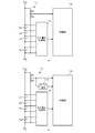
- FIG. 1 is a diagram for explaining a power storage system 1 according to Embodiment 1 of the present invention.
- the example shown in FIG. 1 is an example in which the power storage system 1 according to the present embodiment is mounted on a vehicle as a driving battery for the vehicle.
- EV / PHEV that can be charged from a commercial power system (hereinafter simply referred to as system 5) is assumed.
- the power storage system 1 is connected to the motor 3 via the first relay SW1 and the inverter 2.
- the inverter 2 converts the DC power supplied from the power storage system 1 into AC power and supplies it to the motor 3 during power running.
- AC power supplied from the motor 3 is converted to DC power and supplied to the power storage system 1.
- the motor 3 is a three-phase AC motor, and rotates according to the AC power supplied from the inverter 2 during power running. At the time of regeneration, the rotational energy due to deceleration is converted into AC power and supplied to the inverter 2.
- 1st relay SW1 is inserted between the wiring which connects the electrical storage module 20 and the inverter 2 of the electrical storage system 1.
- FIG. When traveling, the management device 10 of the power storage system 1 controls the first relay SW1 to an on state (closed state), and electrically connects the power storage module 20 and the power system of the vehicle.
- the management device 10 controls the first relay SW1 to an off state (open state) as a general rule when the vehicle is not traveling, and electrically shuts off the power storage module 20 and the power system of the vehicle.
- switches such as semiconductor switches may be used instead of relays.
- the power storage system 1 includes a power storage module 20 and a management device 10.
- the power storage module 20 is formed by connecting a plurality of cells E1-Em in series.
- a lithium ion battery cell a nickel metal hydride battery cell, a lead battery cell, an electric double layer capacitor cell, a lithium ion capacitor cell, or the like can be used.
- a lithium ion battery cell nominal voltage: 3.6-3.7 V
- the number of cells E1-Em in series is determined according to the drive voltage of the motor 3.
- a shunt resistor Rs is connected in series with a plurality of cells E1-Em.
- the shunt resistor Rs functions as a current detection element.
- a Hall element may be used instead of the shunt resistor Rs.
- a temperature sensor T1 for detecting the temperature of the plurality of cells E1-Em is installed.
- a thermistor can be used as the temperature sensor T1.
- the management device 10 includes a total voltage measurement unit 11, a cell voltage measurement unit 12, a temperature measurement unit 13, a current measurement unit 14, a control unit 15, and a drive unit 16.
- the total voltage measuring unit 11 measures the voltage (total voltage) across the plurality of cells E1-Em connected in series. A configuration example of the total voltage measurement unit 11 will be described later.
- the cell voltage measurement unit 12 is connected to each node of a plurality of cells E1-Em connected in series by a plurality of voltage lines, and measures each voltage between two adjacent voltage lines, thereby allowing each cell E1- Measure Em voltage.
- the cell voltage measurement unit 12 transmits the measured voltage of each cell E1-Em to the control unit 15. Since the cell voltage measurement unit 12 has a higher voltage than the control unit 15, the cell voltage measurement unit 12 and the control unit 15 are connected by a communication line in an insulated state.
- the cell voltage measurement unit 12 can be configured by a general-purpose analog front-end IC or ASIC (Application Specific Integrated Circuit).
- the cell voltage measurement unit 12 includes a multiplexer and an A / D converter.
- the multiplexer outputs the voltage between two adjacent voltage lines to the A / D converter in order from the top.
- the A / D converter converts the analog voltage input from the multiplexer into a digital value.
- the large and expensive cell voltage measuring unit 12 is used, in addition to the multiplexer and the A / D converter, the number of differential amplifiers corresponding to the number of cells is included. Each differential amplifier amplifies the voltage between two adjacent voltage lines and outputs the amplified voltage to the multiplexer.
- the temperature measurement unit 13 includes a voltage dividing resistor and an A / D converter.
- the A / D converter converts the voltage divided by the temperature sensor T1 and the voltage dividing resistor into a digital value and outputs the digital value to the control unit 15.
- the controller 15 estimates the temperatures of the plurality of cells E1-Em based on the digital value.
- the current measuring unit 14 includes a differential amplifier and an A / D converter.
- the differential amplifier amplifies the voltage across the shunt resistor Rs and outputs it to the A / D converter.
- the A / D converter converts the voltage input from the differential amplifier into a digital value and outputs the digital value to the control unit 15.
- the control unit 15 estimates the current flowing through the plurality of cells E1-Em based on the digital value.
- the temperature measurement unit 13 and the current measurement unit 14 When an A / D converter is mounted in the control unit 15 and an analog input port is installed in the control unit 15, the temperature measurement unit 13 and the current measurement unit 14 output an analog voltage to the control unit 15.
- the digital value may be converted by an A / D converter in the control unit 15.
- the drive unit 16 generates a drive signal for opening and closing the first relay SW1 or the second relay SW2 based on the control signal from the control unit 15, and supplies the drive signal to the first relay SW1 or the second relay SW2.
- the control unit 15 is based on the total voltage, each voltage, current, and temperature of the plurality of cells E1-Em measured by the total voltage measurement unit 11, the cell voltage measurement unit 12, the temperature measurement unit 13, and the current measurement unit 14.
- the power storage module 20 is managed. For example, when an overvoltage, undervoltage, overcurrent, or temperature abnormality occurs in at least one of the plurality of cells E1-Em, the control unit 15 controls the drive unit 16 to turn on the first relay SW1 and / or the second relay SW2. Turn off and protect multiple cells E1-Em.
- the control unit 15 includes a calculation unit 15a and an internal impedance table 15b.
- the control unit 15 can be constituted by a microcomputer and a nonvolatile memory (for example, EEPROM, flash memory).
- the calculation unit 15a estimates the SOC (State Of Charge) and SOH (State Of Health) of each of the plurality of cells E1-Em.
- the SOC can be estimated by an OCV (Open Circuit Voltage) method or a current integration method.
- the OCV method is a method of estimating the SOC based on the OCV of each cell E1-Em measured by the cell voltage measuring unit 12 and the characteristic data of the SOC-OCV curve held in the nonvolatile memory.
- the current integrating method is a method of estimating the SOC based on the OCV at the start of charging / discharging of each cell E1-Em measured by the cell voltage measuring unit 12 and the integrated value of the current measured by the current measuring unit 14. is there.
- SOH is defined by the ratio of the current full charge capacity to the initial full charge capacity, and indicates that the lower the value (closer to 0%), the more the deterioration progresses.
- SOH may be obtained by capacity measurement by complete charge / discharge, or may be obtained by adding storage deterioration and cycle deterioration.
- Storage degradation can be estimated based on SOC, temperature, and storage degradation rate.
- Cycle degradation can be estimated based on the SOC range used, temperature, current rate, and cycle degradation rate.
- the storage deterioration rate and the cycle deterioration rate can be derived in advance by experiments or simulations.
- the SOC, temperature, SOC range, and current rate can be obtained by measurement.
- SOH can be estimated based on the correlation with the internal resistance of the cell.
- the internal resistance can be estimated by dividing a voltage drop generated when a predetermined current flows through the cell for a predetermined time by the current value.
- the internal resistance has a relationship that decreases as the temperature increases, and increases as the SOH decreases.
- Cell deterioration progresses as the number of charge / discharge cycles increases. Cell degradation also depends on individual differences and usage environment. Therefore, as the usage period becomes longer, the variation in the capacity of the plurality of cells E1-Em basically increases.
- the calculation unit 15a records the operation history including the voltage, current, temperature, SOC, and SOH of each cell E1-Em in the nonvolatile memory.
- An internal impedance table 15b is held in the nonvolatile memory.
- the internal impedance table 15b is a table describing a characteristic map of the internal impedance according to SOH, SOC, and temperature of the cell used in the power storage module 20.
- the characteristic map of the internal impedance can be derived based on experimental data measured while changing the conditions of SOH, SOC, and temperature, or simulation data calculated while changing these conditions.
- the present embodiment measures a ripple component corresponding to a frequency (100 Hz or 120 Hz in Japan) that is twice the commercial power frequency (50 Hz or 60 Hz in Japan) superimposed from the system 5.
- the characteristic map of the internal impedance is derived on the assumption that a voltage on which a ripple component having a frequency twice the commercial power supply frequency is superimposed is applied to the cell.
- a characteristic map of internal impedance for each frequency band may be derived in advance and described in the internal impedance table 15b.
- the power storage system 1 can be charged from the system 5 by being connected to the charger 4 installed outside the vehicle with the charging cable.
- the charger 4 is installed in a home, a card dealer, a service area, a commercial facility, a public facility, or the like.
- the charger 4 is connected to the system 5 and charges the power storage system 1 in the vehicle via a charging cable.
- the second relay SW2 is inserted between the wires connecting the power storage module 20 and the charger 4.
- the management device 10 controls the second relay SW2 to the on state (closed state) at the start of charging, and controls the second relay SW2 to the off state (open state) when the charging is completed.
- the management device 10 turns off the second relay SW2 when detecting an overvoltage, undervoltage, overcurrent, or temperature abnormality in at least one of the plurality of cells E1-Em, and turns off the plurality of cells.
- Protect E1-Em is inserted between the wires connecting the power storage module 20 and the charger 4.
- Charger 4 full-wave rectifies the AC power supplied from system 5 and smoothes it with a filter. Since it is difficult to remove all periodic components with a filter, a ripple component twice the commercial power supply frequency is superimposed on the output power of the charger 4.
- the high-spec charger removes ripple components from the output current including the high power factor converter called PFC (Power Factor Correction) circuit to suppress the harmonic current during charging, and the low frequency ripple of the PFC circuit, Since the DC / DC converter that controls the charging current is composed of two converters, the ripple of the output current of the charger is small.
- many low-spec chargers are configured to control the charging current with a PFC circuit. In that case, the ripple of the output current of the charger becomes large.
- FIG. 2 is a diagram illustrating an example of output waveforms of a charging current and a storage module voltage when charged with a low-spec charger.
- the example shown in FIG. 2 is an example of a state where the power storage module 20 is charged at a voltage of about 48 V, a charging current of about 23 A, and a charging power of about 1100 W.
- the pulsation of the charging current is increased. Since it is expected that such chargers will increase in the future, it is important to take measures against ripples on the power storage system 1 side.
- FIGS. 3A to 3C are diagrams for explaining the influence of the ripple of the charging current flowing from the low-spec charger to the cell.
- FIG. 3A is a diagram showing a simple equivalent circuit of the cell E1.
- the cell E1 is composed of a series circuit of an electromotive force E and an internal resistance Ri.
- FIG. 3B shows a waveform of the charging current i flowing through the cell E1 when charged from a low-spec charger.
- FIG.3 (c) is a figure which shows the voltage waveform of the cell E1 at the time of charging from a low specification charger.
- the voltage of the cell E1 also pulsates due to the influence.
- the ripple of the cell voltage is represented by a peak peak value that is a difference between the maximum voltage value and the minimum voltage value in a unit cycle. Note that the ripple of the cell voltage can be expressed by a maximum voltage value or a minimum voltage value with respect to a DC component in a unit cycle.
- the ripple of the cell voltage is a minute voltage fluctuation, a highly accurate voltage measurement circuit is required. It is also necessary to sample the cell voltage at a sampling frequency that is twice or more the ripple frequency. Therefore, it is conceivable to mount a high-spec cell voltage measurement unit 12.
- the high-spec cell voltage measurement unit 12 when the high-spec cell voltage measurement unit 12 is mounted, the cost increases and the circuit scale also increases. Especially in in-vehicle applications, the number of cells connected in series increases, so the system size and cost increase significantly. Therefore, in the present embodiment, a mechanism for estimating the ripple of each cell voltage from the ripple of the total voltage of the plurality of cells E1-Em is introduced.
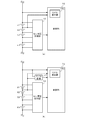
- FIGS. 4A to 4B are partial circuit diagrams showing a configuration example of the total voltage measuring unit 11.
- the total voltage measuring unit 11 includes a first voltage dividing resistor R1 and a second voltage dividing resistor R2 connected in series.
- the voltage divided by the first voltage dividing resistor R1 and the second voltage dividing resistor R2 is input to the analog input port of the control unit 15.
- An operational amplifier may be inserted between the voltage dividing circuit and the control unit 15.
- the control unit 15 samples the input voltage at a sampling frequency that is at least four times the commercial power supply frequency.
- the controller 15 detects the ripple of the total voltage by specifying the maximum voltage value and the minimum voltage value in the predetermined period.
- the predetermined period is set to a period corresponding to a frequency twice the commercial power supply frequency.
- the total voltage measuring unit 11 includes a first voltage dividing resistor R1 and a second voltage dividing resistor R2 connected in series, and a peak hold circuit 11a.
- a voltage divided by the first voltage dividing resistor R1 and the second voltage dividing resistor R2 is applied to the input terminal of the peak hold circuit 11a.
- the peak hold circuit 11a a general peak hold circuit using an operational amplifier, a diode, and a capacitor can be used.
- the peak hold circuit 11a can output the maximum voltage value or the minimum voltage value to the control unit 15 by resetting the capacitor every half cycle of the ripple cycle. In this configuration example, the control unit 15 can lower the sampling frequency.
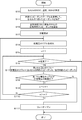
- FIG. 5 is a flowchart for explaining a ripple measuring method of power storage system 1 according to the first embodiment of the present invention.
- the control unit 15 of the management apparatus 10 specifies the SOC, temperature, and SOH of each cell E1-Em (S10).
- the control unit 15 specifies the internal impedance of each cell E1-Em with reference to the internal impedance table 15b based on the SOC, temperature, and SOH of each specified cell E1-Em (S11).
- the control unit 15 adds the internal impedances of the specified cells E1-Em, and calculates a combined internal impedance of the plurality of cells E1-Em connected in series (S12).
- the control unit 15 When charging of the power storage module 20 from the charger 4 is started (S13), the control unit 15 detects a ripple of the total voltage based on the voltage input from the total voltage measuring unit 11 (S14). The control unit 15 substitutes 1 as an initial value for the parameter n (S15).
- Control unit 15 monitors whether or not charging is completed (S16). When the charging is completed (Y in S16), the ripple measurement process is terminated. During charging (N in S16), the control unit 15 calculates the ripple of the nth cell voltage using the following (Equation 1) (S17).
- N ripple of nth cell voltage ripple of total voltage * (internal impedance / synthetic impedance of nth cell) (Equation 1)
- the control unit 15 determines whether or not the ripple of the nth cell voltage is within the allowable voltage range of the cell (S18). When the ripple of the nth cell voltage exceeds the allowable voltage range of the cell (N of S18) The control unit 15 opens the second relay SW2 (S111) and ends the ripple measurement process. When the ripple of the nth cell voltage is within the allowable voltage range of the cell (Y in S18), the control unit 15 increments the parameter n (S19). The control unit 15 compares the parameter n with the serial number m (S110). If the parameter n is equal to or smaller than the serial number m (N in S110), the process proceeds to step S16. When the parameter n exceeds the serial number m (Y in S110), the process proceeds to step S14.
- the ripple of each cell voltage is estimated by multiplying the ripple of the total voltage by the ratio of the internal impedance of each cell to the combined internal impedance of a plurality of cells.
- FIG. 6 is a flowchart for explaining a ripple measuring method of power storage system 1 according to Embodiment 2 of the present invention.
- the control unit 15 of the management device 10 instructs the charger 4 to supply a constant current to the power storage module 20 for a predetermined period before starting charging from the charger 4 (S20).
- the control unit 15 can transmit the instruction to the charger 4 through communication using the communication line. Power line communication can also be used.
- the constant current value is preferably set to a small value.
- the control unit 15 detects the voltage change of each cell E1-Em before and after the supply of the constant current from the charger 4 (S21).
- the control unit 15 calculates the internal impedance of each cell E1-Em based on the constant current value supplied from the charger 4 and the voltage change value of each cell E1-Em (S22).
- the control unit 15 adds up the calculated internal impedances of the cells E1-Em to calculate a combined internal impedance of the plurality of cells E1-Em connected in series (S23).
- the processing from step S24 to step S212 is the same as the processing from step S13 to step S111 in the flowchart of FIG.
- the same effects as those of the first embodiment can be obtained. Furthermore, in the second embodiment, the internal impedance table 15b is unnecessary, so that development costs can be suppressed. Moreover, since the internal impedance of each cell E1-Em is measured based on the constant current from the charger 4 used for charging, high accuracy reflecting the ripple component superimposed from the charger 4 used for charging and the environmental conditions. Can be obtained.
- the ripple measurement method for the power storage system 1 according to Embodiment 3 of the present invention will be described.
- the total voltage of the plurality of cells E1-Em is measured, and the ripple of the cell voltage of one cell E1 is detected without detecting the ripple of the total voltage.
- the ratio of the internal impedance of one cell E1 and the internal impedance of each of the other cells E2-Em is multiplied by the ripple of the cell voltage of one cell E1, and the ripple of the cell voltage of each of the other cells E2-Em is obtained. presume.
- FIGS. 7A to 7B are partial circuit diagrams showing a configuration example according to the third embodiment.
- the total voltage measuring unit 11 is omitted.
- the ripple detector 15c in the controller 15 detects a ripple of the cell voltage of one cell E1.
- the ripple of the total voltage of the plurality of cells E1-Em is detected by the ripple detector 15c in the controller 15.
- the structure which provides the ripple detection part 15c independently outside the control part 15 is also possible.
- the ripple of each cell voltage except one is changed to the ripple of the cell voltage of one cell, and the internal impedance of the one cell and the internal impedances of the other cells are It is estimated by multiplying by the ratio. As a result, only one measurement of the cell voltage ripple needs to be performed, and an increase in the system size and cost of the cell voltage measurement unit 12 can be suppressed.
- the above-described ripple measurement method can also be used in the stationary power storage system 1.
- the above ripple measurement method can also be used in the power storage system 1 for electronic devices such as notebook PCs and smartphones.
- a management device (10) characterized by estimating the ripple of each cell voltage by multiplying the ratio of the internal impedance of each cell (En) and determining whether the ripple of each cell voltage is within the allowable voltage range.
- the management device (10) according to any one of 1 to 4. According to this, the internal impedance of each cell (En) can be estimated with high accuracy.
- the controller (15) estimates an internal impedance of each cell (En) based on a voltage change of each cell (En) before and after a predetermined current is supplied to the plurality of cells (E1-Em).
- the management apparatus (10) according to any one of items 1 to 4, characterized in that: According to this, the internal impedance of each cell (En) can be estimated with high accuracy.
- the management device (10) according to any one of items 1 to 6, which manages the plurality of cells (E1-Em);
- a power storage system (1) comprising: According to this, it is possible to construct a power storage system (1) that can measure the ripple of each voltage of a plurality of cells (E1-Em) with an inexpensive and small-scale circuit.
Landscapes
- Engineering & Computer Science (AREA)
- Physics & Mathematics (AREA)
- General Physics & Mathematics (AREA)
- Power Engineering (AREA)
- Chemical Kinetics & Catalysis (AREA)
- General Chemical & Material Sciences (AREA)
- Electrochemistry (AREA)
- Manufacturing & Machinery (AREA)
- Chemical & Material Sciences (AREA)
- Health & Medical Sciences (AREA)
- Medical Informatics (AREA)
- General Health & Medical Sciences (AREA)
- Microelectronics & Electronic Packaging (AREA)
- Charge And Discharge Circuits For Batteries Or The Like (AREA)
- Secondary Cells (AREA)
- Tests Of Electric Status Of Batteries (AREA)
Abstract
A cell voltage measuring unit (12) measures the voltages across each of a plurality of cells (E1 to Em) connected in series. A total voltage measuring unit (11) measures the total voltage across the plurality of cells (E1 to Em). A control unit (15) manages the internal impedance of each of the plurality of cells (E1 to Em). The control unit (15) detects a ripple in the total voltage measured by the total voltage measuring unit (11), estimates a ripple in each cell voltage by multiplying the detected ripple in the total voltage by a ratio of the internal impedance of each cell to a composite internal impedance of the plurality of cells (E1 to Em), and determines whether the ripple in each cell voltage lies within a permitted voltage rage.
Description
本発明は、直列接続された複数のセルの状態を管理する管理装置、蓄電システムに関する。
The present invention relates to a management device and a power storage system that manage the states of a plurality of cells connected in series.
近年、リチウムイオン電池やニッケル水素電池などの二次電池の需要が拡大している。二次電池は車載用途、定置型蓄電用途(例えば、バックアップ、ピークシフト、FR(Frequency Regulation))など、様々な用途に使用されている。特に近年、EV(Electric Vehicle)、PHEV(Plug-in Hybrid Electric Vehicle)の出荷台数が増えてきており、車外に設置された充電器からEV/PHEVに充電することが増えてきている。
Recently, demand for secondary batteries such as lithium ion batteries and nickel metal hydride batteries is expanding. Secondary batteries are used in various applications such as in-vehicle applications and stationary power storage applications (for example, backup, peak shift, FR (Frequency Regulation)). In particular, in recent years, the number of EV (Electric (Vehicle) and PHEV (Plug-in Hybrid Electric Vehicle) shipments has increased, and charging to EV / PHEV from a charger installed outside the vehicle has increased.
それに伴い安価で低スペックな充電器が使用されるケースが増えてきている。低スペックな充電器では、商用電源系統の交流電力を整流した際のリプル成分を十分に除去することができず、大きなリプル成分が重畳された電流が二次電池に流れ込んでくることになる。定置型蓄電用途でもパワーコンディショナの小型化、低コスト化が求められており、それに伴い大きなリプル成分が重畳された電流が二次電池に流れ込んでくる場合がある。
Along with this, the number of cases where inexpensive and low-spec chargers are used is increasing. In the low-spec charger, the ripple component when the AC power of the commercial power supply system is rectified cannot be sufficiently removed, and a current with a large ripple component flowing into the secondary battery. There is a demand for miniaturization and cost reduction of power conditioners even for stationary power storage applications, and in accordance therewith, a current with a large ripple component may flow into the secondary battery.
直列接続された複数のセルを含む蓄電システムでは、セル毎に電圧を計測し、セル電圧が許容電圧の範囲内にあるか否か監視している(例えば、特許文献1参照)。低スペックな充電器から充電される場合、リプル電流の影響によりセル電圧が脈動し、セルの許容電圧範囲を超える懸念がある。
In a power storage system including a plurality of cells connected in series, a voltage is measured for each cell, and it is monitored whether the cell voltage is within an allowable voltage range (see, for example, Patent Document 1). When charging from a low-spec charger, the cell voltage pulsates due to the influence of the ripple current, which may exceed the allowable voltage range of the cell.
セル電圧のリプルは微小な電圧変動であるため、セル電圧のリプルを高精度に監視するには高精度な電圧計測回路が必要となる。またリプル周波数の倍以上のサンプリング周波数でセル電圧をサンプリングする必要がある。これを実現するには、高価でサイズが大きい電圧計測回路(例えば、アナログフロントエンドIC)が必要となる。特にセルの直列数が多くなるほど回路規模が大きくなり、システムサイズやコストが増大する。
Since the cell voltage ripple is a minute voltage fluctuation, a highly accurate voltage measurement circuit is required to monitor the cell voltage ripple with high accuracy. It is also necessary to sample the cell voltage at a sampling frequency that is twice or more the ripple frequency. To realize this, an expensive and large voltage measuring circuit (for example, an analog front end IC) is required. In particular, as the number of cells in series increases, the circuit scale increases and the system size and cost increase.
本発明はこうした状況に鑑みなされたものであり、その目的は、直列接続された複数のセルの各電圧のリプルを安価で小規模な回路で計測することができる技術を提供することにある。
The present invention has been made in view of such a situation, and an object of the present invention is to provide a technology capable of measuring ripples of respective voltages of a plurality of cells connected in series with an inexpensive and small circuit.
上記課題を解決するために、本発明のある態様の管理装置は、直列接続された複数のセルのそれぞれの電圧を計測するセル電圧計測部と、前記複数のセルの総電圧を計測する総電圧計測部と、前記複数のセルのそれぞれの内部インピーダンスを管理する制御部と、を備える。前記制御部は、前記総電圧計測部により計測された総電圧のリプルを検出し、検出した総電圧のリプルに、前記複数のセルの合成内部インピーダンスに対する各セルの内部インピーダンスの比率を乗じて各セル電圧のリプルを推定し、各セル電圧のリプルが許容電圧の範囲内か否か判定する。
In order to solve the above problems, a management device according to an aspect of the present invention includes a cell voltage measurement unit that measures voltages of a plurality of cells connected in series, and a total voltage that measures a total voltage of the plurality of cells. A measurement unit; and a control unit that manages internal impedances of the plurality of cells. The control unit detects the ripple of the total voltage measured by the total voltage measurement unit, and multiplies the detected ripple of the total voltage by the ratio of the internal impedance of each cell to the combined internal impedance of the plurality of cells. The ripple of the cell voltage is estimated, and it is determined whether or not the ripple of each cell voltage is within the allowable voltage range.
本発明によれば、直列接続された複数のセルの各電圧のリプルを安価で小規模な回路で計測することができる。
According to the present invention, the ripple of each voltage of a plurality of cells connected in series can be measured with an inexpensive and small circuit.
図1は、本発明の実施の形態1に係る蓄電システム1を説明するための図である。図1に示す例は、本実施の形態に係る蓄電システム1が、車両の駆動用電池として車両に搭載される例である。当該車両として、商用電力系統(以下、単に系統5という)から充電可能なEV/PHEVを想定する。
FIG. 1 is a diagram for explaining a power storage system 1 according to Embodiment 1 of the present invention. The example shown in FIG. 1 is an example in which the power storage system 1 according to the present embodiment is mounted on a vehicle as a driving battery for the vehicle. As the vehicle, EV / PHEV that can be charged from a commercial power system (hereinafter simply referred to as system 5) is assumed.
蓄電システム1は、第1リレーSW1及びインバータ2を介してモータ3に接続される。インバータ2は力行時、蓄電システム1から供給される直流電力を交流電力に変換してモータ3に供給する。回生時、モータ3から供給される交流電力を直流電力に変換して蓄電システム1に供給する。モータ3は三相交流モータであり、力行時、インバータ2から供給される交流電力に応じて回転する。回生時、減速による回転エネルギーを交流電力に変換してインバータ2に供給する。
The power storage system 1 is connected to the motor 3 via the first relay SW1 and the inverter 2. The inverter 2 converts the DC power supplied from the power storage system 1 into AC power and supplies it to the motor 3 during power running. During regeneration, AC power supplied from the motor 3 is converted to DC power and supplied to the power storage system 1. The motor 3 is a three-phase AC motor, and rotates according to the AC power supplied from the inverter 2 during power running. At the time of regeneration, the rotational energy due to deceleration is converted into AC power and supplied to the inverter 2.
第1リレーSW1は蓄電システム1の蓄電モジュール20とインバータ2を繋ぐ配線間に挿入される。蓄電システム1の管理装置10は走行時、第1リレーSW1をオン状態(閉状態)に制御し、蓄電モジュール20と車両の動力系を電気的に接続する。管理装置10は非走行時、原則として第1リレーSW1をオフ状態(開状態)に制御し、蓄電モジュール20と車両の動力系を電気的に遮断する。なおリレーの代わりに、半導体スイッチなどの他の種類のスイッチを用いてもよい。
1st relay SW1 is inserted between the wiring which connects the electrical storage module 20 and the inverter 2 of the electrical storage system 1. FIG. When traveling, the management device 10 of the power storage system 1 controls the first relay SW1 to an on state (closed state), and electrically connects the power storage module 20 and the power system of the vehicle. The management device 10 controls the first relay SW1 to an off state (open state) as a general rule when the vehicle is not traveling, and electrically shuts off the power storage module 20 and the power system of the vehicle. Note that other types of switches such as semiconductor switches may be used instead of relays.
蓄電システム1は蓄電モジュール20及び管理装置10を備える。蓄電モジュール20は複数のセルE1-Emが直列接続されて形成される。セルには、リチウムイオン電池セル、ニッケル水素電池セル、鉛電池セル、電気二重層キャパシタセル、リチウムイオンキャパシタセル等を用いることができる。以下、本明細書ではリチウムイオン電池セル(公称電圧:3.6-3.7V)を使用する例を想定する。セルE1-Emの直列数は、モータ3の駆動電圧に応じて決定される。
The power storage system 1 includes a power storage module 20 and a management device 10. The power storage module 20 is formed by connecting a plurality of cells E1-Em in series. As the cell, a lithium ion battery cell, a nickel metal hydride battery cell, a lead battery cell, an electric double layer capacitor cell, a lithium ion capacitor cell, or the like can be used. Hereinafter, in this specification, an example in which a lithium ion battery cell (nominal voltage: 3.6-3.7 V) is used is assumed. The number of cells E1-Em in series is determined according to the drive voltage of the motor 3.
複数のセルE1-Emと直列にシャント抵抗Rsが接続される。シャント抵抗Rsは電流検出素子として機能する。なおシャント抵抗Rsの代わりにホール素子を用いてもよい。また複数のセルE1-Emの温度を検出するための温度センサT1が設置される。温度センサT1には例えば、サーミスタを使用することができる。
A shunt resistor Rs is connected in series with a plurality of cells E1-Em. The shunt resistor Rs functions as a current detection element. A Hall element may be used instead of the shunt resistor Rs. Further, a temperature sensor T1 for detecting the temperature of the plurality of cells E1-Em is installed. For example, a thermistor can be used as the temperature sensor T1.
管理装置10は総電圧計測部11、セル電圧計測部12、温度計測部13、電流計測部14、制御部15及び駆動部16を備える。総電圧計測部11は、直列接続された複数のセルE1-Emの両端電圧(総電圧)を計測する。総電圧計測部11の構成例は後述する。
The management device 10 includes a total voltage measurement unit 11, a cell voltage measurement unit 12, a temperature measurement unit 13, a current measurement unit 14, a control unit 15, and a drive unit 16. The total voltage measuring unit 11 measures the voltage (total voltage) across the plurality of cells E1-Em connected in series. A configuration example of the total voltage measurement unit 11 will be described later.
セル電圧計測部12は、直列接続された複数のセルE1-Emの各ノードと複数の電圧線で接続され、隣接する2本の電圧線間の電圧をそれぞれ計測することにより、各セルE1-Emの電圧を計測する。セル電圧計測部12は、計測した各セルE1-Emの電圧を制御部15に送信する。セル電圧計測部12は制御部15に対して高圧であるため、セル電圧計測部12と制御部15間は絶縁された状態で、通信線で接続される。
The cell voltage measurement unit 12 is connected to each node of a plurality of cells E1-Em connected in series by a plurality of voltage lines, and measures each voltage between two adjacent voltage lines, thereby allowing each cell E1- Measure Em voltage. The cell voltage measurement unit 12 transmits the measured voltage of each cell E1-Em to the control unit 15. Since the cell voltage measurement unit 12 has a higher voltage than the control unit 15, the cell voltage measurement unit 12 and the control unit 15 are connected by a communication line in an insulated state.
セル電圧計測部12は、汎用のアナログフロントエンドICまたはASIC(Application Specific Integrated Circuit)で構成することができる。小型で安価なセル電圧計測部12を使用する場合、セル電圧計測部12はマルチプレクサ及びA/D変換器を含む。マルチプレクサは、隣接する2本の電圧線間の電圧を上から順番にA/D変換器に出力する。A/D変換器は、マルチプレクサから入力されるアナログ電圧をデジタル値に変換する。大型で高価なセル電圧計測部12を使用する場合、マルチプレクサ及びA/D変換器に加えて、セルの数に対応した数の差動アンプが含まれる。各差動アンプは、隣接する2本の電圧線間の電圧を増幅してマルチプレクサに出力する。
The cell voltage measurement unit 12 can be configured by a general-purpose analog front-end IC or ASIC (Application Specific Integrated Circuit). When the small and inexpensive cell voltage measurement unit 12 is used, the cell voltage measurement unit 12 includes a multiplexer and an A / D converter. The multiplexer outputs the voltage between two adjacent voltage lines to the A / D converter in order from the top. The A / D converter converts the analog voltage input from the multiplexer into a digital value. When the large and expensive cell voltage measuring unit 12 is used, in addition to the multiplexer and the A / D converter, the number of differential amplifiers corresponding to the number of cells is included. Each differential amplifier amplifies the voltage between two adjacent voltage lines and outputs the amplified voltage to the multiplexer.
温度計測部13は分圧抵抗およびA/D変換器を含む。A/D変換器は、温度センサT1と分圧抵抗により分圧された電圧をデジタル値に変換して制御部15に出力する。制御部15は当該デジタル値をもとに複数のセルE1-Emの温度を推定する。
The temperature measurement unit 13 includes a voltage dividing resistor and an A / D converter. The A / D converter converts the voltage divided by the temperature sensor T1 and the voltage dividing resistor into a digital value and outputs the digital value to the control unit 15. The controller 15 estimates the temperatures of the plurality of cells E1-Em based on the digital value.
電流計測部14は差動アンプ及びA/D変換器を含む。差動アンプはシャント抵抗Rsの両端電圧を増幅してA/D変換器に出力する。A/D変換器は、差動アンプから入力される電圧をデジタル値に変換して制御部15に出力する。制御部15は当該デジタル値をもとに複数のセルE1-Emに流れる電流を推定する。
The current measuring unit 14 includes a differential amplifier and an A / D converter. The differential amplifier amplifies the voltage across the shunt resistor Rs and outputs it to the A / D converter. The A / D converter converts the voltage input from the differential amplifier into a digital value and outputs the digital value to the control unit 15. The control unit 15 estimates the current flowing through the plurality of cells E1-Em based on the digital value.
なお制御部15内にA/D変換器が搭載されており、制御部15にアナログ入力ポートが設置されている場合、温度計測部13及び電流計測部14はアナログ電圧を制御部15に出力し、制御部15内のA/D変換器でデジタル値に変換してもよい。
When an A / D converter is mounted in the control unit 15 and an analog input port is installed in the control unit 15, the temperature measurement unit 13 and the current measurement unit 14 output an analog voltage to the control unit 15. The digital value may be converted by an A / D converter in the control unit 15.
駆動部16は、制御部15からの制御信号をもとに第1リレーSW1または第2リレーSW2を開閉するための駆動信号を生成し、第1リレーSW1または第2リレーSW2に供給する。
The drive unit 16 generates a drive signal for opening and closing the first relay SW1 or the second relay SW2 based on the control signal from the control unit 15, and supplies the drive signal to the first relay SW1 or the second relay SW2.
制御部15は、総電圧計測部11、セル電圧計測部12、温度計測部13及び電流計測部14により計測された複数のセルE1-Emの総電圧、各電圧、電流、及び温度をもとに蓄電モジュール20を管理する。例えば制御部15は、複数のセルE1-Emの少なくとも1つに過電圧、過小電圧、過電流、温度異常が発生すると、駆動部16を制御して第1リレーSW1及び/又は第2リレーSW2をターンオフさせ、複数のセルE1-Emを保護する。
The control unit 15 is based on the total voltage, each voltage, current, and temperature of the plurality of cells E1-Em measured by the total voltage measurement unit 11, the cell voltage measurement unit 12, the temperature measurement unit 13, and the current measurement unit 14. The power storage module 20 is managed. For example, when an overvoltage, undervoltage, overcurrent, or temperature abnormality occurs in at least one of the plurality of cells E1-Em, the control unit 15 controls the drive unit 16 to turn on the first relay SW1 and / or the second relay SW2. Turn off and protect multiple cells E1-Em.
制御部15は、演算部15a及び内部インピーダンステーブル15bを含む。制御部15はマイクロコンピュータ及び不揮発メモリ(例えば、EEPROM、フラッシュメモリ)により構成することができる。
The control unit 15 includes a calculation unit 15a and an internal impedance table 15b. The control unit 15 can be constituted by a microcomputer and a nonvolatile memory (for example, EEPROM, flash memory).
演算部15aは、複数のセルE1-EmのそれぞれのSOC(State Of Charge)及びSOH(State Of Health)を推定する。SOCは、OCV(Open Circuit Voltage)法または電流積算法により推定できる。OCV法は、セル電圧計測部12により計測される各セルE1-EmのOCVと、不揮発メモリに保持されるSOC-OCVカーブの特性データをもとにSOCを推定する方法である。電流積算法は、セル電圧計測部12により計測される各セルE1-Emの充放電開始時のOCVと、電流計測部14により計測される電流の積算値をもとにSOCを推定する方法である。
The calculation unit 15a estimates the SOC (State Of Charge) and SOH (State Of Health) of each of the plurality of cells E1-Em. The SOC can be estimated by an OCV (Open Circuit Voltage) method or a current integration method. The OCV method is a method of estimating the SOC based on the OCV of each cell E1-Em measured by the cell voltage measuring unit 12 and the characteristic data of the SOC-OCV curve held in the nonvolatile memory. The current integrating method is a method of estimating the SOC based on the OCV at the start of charging / discharging of each cell E1-Em measured by the cell voltage measuring unit 12 and the integrated value of the current measured by the current measuring unit 14. is there.
SOHは、初期の満充電容量に対する現在の満充電容量の比率で規定され、数値が低いほど(0%に近いほど)劣化が進行していることを示す。SOHは、完全充放電による容量計測により求めてもよいし、保存劣化とサイクル劣化を合算することにより求めてもよい。保存劣化はSOC、温度、及び保存劣化速度をもとに推定することができる。サイクル劣化は、使用するSOC範囲、温度、電流レート、及びサイクル劣化速度をもとに推定することができる。保存劣化速度およびサイクル劣化速度は、予め実験やシミュレーションにより導出することができる。SOC、温度、SOC範囲、及び電流レートは計測により取得することができる。
SOH is defined by the ratio of the current full charge capacity to the initial full charge capacity, and indicates that the lower the value (closer to 0%), the more the deterioration progresses. SOH may be obtained by capacity measurement by complete charge / discharge, or may be obtained by adding storage deterioration and cycle deterioration. Storage degradation can be estimated based on SOC, temperature, and storage degradation rate. Cycle degradation can be estimated based on the SOC range used, temperature, current rate, and cycle degradation rate. The storage deterioration rate and the cycle deterioration rate can be derived in advance by experiments or simulations. The SOC, temperature, SOC range, and current rate can be obtained by measurement.
またSOHは、セルの内部抵抗との相関関係をもとに推定することもできる。内部抵抗は、セルに所定の電流を所定時間流した際に発生する電圧降下を、当該電流値で割ることにより推定することができる。内部抵抗は温度が上がるほど低下する関係にあり、SOHが低下するほど増加する関係にある。セルの劣化は充放電回数が増加するにつれ進行する。またセルの劣化は個体差や使用環境にも依存する。従って使用期間が長くになるにつれ基本的に、複数のセルE1-Emの容量のばらつきが大きくなっていく。
Also, SOH can be estimated based on the correlation with the internal resistance of the cell. The internal resistance can be estimated by dividing a voltage drop generated when a predetermined current flows through the cell for a predetermined time by the current value. The internal resistance has a relationship that decreases as the temperature increases, and increases as the SOH decreases. Cell deterioration progresses as the number of charge / discharge cycles increases. Cell degradation also depends on individual differences and usage environment. Therefore, as the usage period becomes longer, the variation in the capacity of the plurality of cells E1-Em basically increases.
演算部15aは、各セルE1-Emの電圧、電流、温度、SOC及びSOHを含む動作履歴を不揮発メモリに記録する。不揮発メモリ内には内部インピーダンステーブル15bが保持されている。内部インピーダンステーブル15bは、蓄電モジュール20に使用されるセルのSOH、SOC及び温度別の内部インピーダンスの特性マップを記述したテーブルである。当該内部インピーダンスの特性マップは、SOH、SOC、温度の条件を変化させながら計測した実験データ、又はそれらの条件を変化させながら算出したシミュレーションデータに基づき導出することができる。
The calculation unit 15a records the operation history including the voltage, current, temperature, SOC, and SOH of each cell E1-Em in the nonvolatile memory. An internal impedance table 15b is held in the nonvolatile memory. The internal impedance table 15b is a table describing a characteristic map of the internal impedance according to SOH, SOC, and temperature of the cell used in the power storage module 20. The characteristic map of the internal impedance can be derived based on experimental data measured while changing the conditions of SOH, SOC, and temperature, or simulation data calculated while changing these conditions.
なお詳細は後述するが、本実施の形態は、系統5から重畳される商用電源周波数(日本では50Hzまたは60Hz)の2倍の周波数(日本では100Hzまたは120Hz)に対応するリプル成分を計測することを目的とする。従って、内部インピーダンスの特性マップは、商用電源周波数の2倍の周波数のリプル成分が重畳された電圧がセルに印加された状態を前提に導出される。なお汎用的なシステムを構築する場合は、周波数帯域別の内部インピーダンスの特性マップを予め導出し、内部インピーダンステーブル15b内に記述しておいてもよい。
Although details will be described later, the present embodiment measures a ripple component corresponding to a frequency (100 Hz or 120 Hz in Japan) that is twice the commercial power frequency (50 Hz or 60 Hz in Japan) superimposed from the system 5. With the goal. Therefore, the characteristic map of the internal impedance is derived on the assumption that a voltage on which a ripple component having a frequency twice the commercial power supply frequency is superimposed is applied to the cell. When a general-purpose system is constructed, a characteristic map of internal impedance for each frequency band may be derived in advance and described in the internal impedance table 15b.
上述のように蓄電システム1は、車両外に設置された充電器4と充電ケーブルで接続することにより系統5から充電することができる。充電器4は、家庭、カーディーラ、サービスエリア、商業施設、公共施設などに設置される。充電器4は系統5に接続され、充電ケーブルを介して車両内の蓄電システム1を充電する。
As described above, the power storage system 1 can be charged from the system 5 by being connected to the charger 4 installed outside the vehicle with the charging cable. The charger 4 is installed in a home, a card dealer, a service area, a commercial facility, a public facility, or the like. The charger 4 is connected to the system 5 and charges the power storage system 1 in the vehicle via a charging cable.
車両内において、蓄電モジュール20と充電器4を繋ぐ配線間に第2リレーSW2が挿入される。なおリレーの代わりに、半導体スイッチなどの他の種類のスイッチを用いてもよい。管理装置10は充電開始時に、第2リレーSW2をオン状態(閉状態)に制御し、充電が終了するとオフ状態(開状態)に制御する。充電器4からの充電中に管理装置10は、複数のセルE1-Emの少なくとも1つに過電圧、過小電圧、過電流、又は温度異常を検出すると第2リレーSW2をターンオフして、複数のセルE1-Emを保護する。
In the vehicle, the second relay SW2 is inserted between the wires connecting the power storage module 20 and the charger 4. Note that other types of switches such as semiconductor switches may be used instead of relays. The management device 10 controls the second relay SW2 to the on state (closed state) at the start of charging, and controls the second relay SW2 to the off state (open state) when the charging is completed. During the charging from the charger 4, the management device 10 turns off the second relay SW2 when detecting an overvoltage, undervoltage, overcurrent, or temperature abnormality in at least one of the plurality of cells E1-Em, and turns off the plurality of cells. Protect E1-Em.
充電器4は、系統5から供給される交流電力を全波整流し、フィルタで平滑化する。フィルタで全ての周期成分を除去することは困難であるため、充電器4の出力電力には、商用電源周波数の2倍のリプル成分が重畳される。
Charger 4 full-wave rectifies the AC power supplied from system 5 and smoothes it with a filter. Since it is difficult to remove all periodic components with a filter, a ripple component twice the commercial power supply frequency is superimposed on the output power of the charger 4.
上述のようにEV/PHEVの普及に伴い、安価で低スペックな充電器が普及してきている。高スペックな充電器は、充電時の高調波電流を抑制するためのPFC(Power Factor Correction)回路と呼ばれる高力率コンバータと、PFC回路の低周波リプルを含む出力電流からリプル成分を除去し、充電電流の制御を行うDC/DCコンバータの、2つのコンバータで構成されるため、充電器の出力電流のリプルは小さなものになる。一方、低スペックな充電器は、PFC回路で充電電流の制御を行う構成であるものが多い。その場合、充電器の出力電流のリプルは大きなものになる。
As described above, with the spread of EV / PHEV, inexpensive and low-spec chargers are becoming popular. The high-spec charger removes ripple components from the output current including the high power factor converter called PFC (Power Factor Correction) circuit to suppress the harmonic current during charging, and the low frequency ripple of the PFC circuit, Since the DC / DC converter that controls the charging current is composed of two converters, the ripple of the output current of the charger is small. On the other hand, many low-spec chargers are configured to control the charging current with a PFC circuit. In that case, the ripple of the output current of the charger becomes large.
図2は、低スペックな充電器で充電したときの充電電流と蓄電モジュール電圧の出力波形の一例を示す図である。図2に示す例は、蓄電モジュール20の電圧が約48V、充電電流が約23A、充電電力が約1100Wで充電している状態の例である。図2に示すように充電電流の脈動が大きくなっている。今後、このような充電器が増えることが予想されるため、蓄電システム1側でのリプル対策が重要となる。
FIG. 2 is a diagram illustrating an example of output waveforms of a charging current and a storage module voltage when charged with a low-spec charger. The example shown in FIG. 2 is an example of a state where the power storage module 20 is charged at a voltage of about 48 V, a charging current of about 23 A, and a charging power of about 1100 W. As shown in FIG. 2, the pulsation of the charging current is increased. Since it is expected that such chargers will increase in the future, it is important to take measures against ripples on the power storage system 1 side.
図3(a)-(c)は、低スペックな充電器からセルに流れる充電電流のリプルの影響を説明するための図である。図3(a)はセルE1の簡易的な等価回路を示す図である。セルE1は、起電力Eと内部抵抗Riの直列回路で構成される。図3(b)は、低スペックな充電器から充電される際のセルE1に流れる充電電流iの波形を示す。図3(c)は、低スペックな充電器から充電される際のセルE1の電圧波形を示す図である。充電電流iの脈動が大きくなると、その影響によりセルE1の電圧も脈動する。セル電圧が脈動すると、セルE1の最大許容電圧を超える確率が高くなる。従って、セルE1に過電圧が印加されているか否かを監視するには、セル電圧のリプルを高精度に計測することが重要となる。セル電圧のリプルは、単位周期における最大電圧値と最小電圧値との差であるピークピーク値で表される。なお、セル電圧のリプルを、単位周期における直流成分に対する最大電圧値または最小電圧値で表すことも可能である。
FIGS. 3A to 3C are diagrams for explaining the influence of the ripple of the charging current flowing from the low-spec charger to the cell. FIG. 3A is a diagram showing a simple equivalent circuit of the cell E1. The cell E1 is composed of a series circuit of an electromotive force E and an internal resistance Ri. FIG. 3B shows a waveform of the charging current i flowing through the cell E1 when charged from a low-spec charger. FIG.3 (c) is a figure which shows the voltage waveform of the cell E1 at the time of charging from a low specification charger. When the pulsation of the charging current i increases, the voltage of the cell E1 also pulsates due to the influence. When the cell voltage pulsates, the probability of exceeding the maximum allowable voltage of the cell E1 increases. Therefore, in order to monitor whether or not an overvoltage is applied to the cell E1, it is important to measure the ripple of the cell voltage with high accuracy. The ripple of the cell voltage is represented by a peak peak value that is a difference between the maximum voltage value and the minimum voltage value in a unit cycle. Note that the ripple of the cell voltage can be expressed by a maximum voltage value or a minimum voltage value with respect to a DC component in a unit cycle.
セル電圧のリプルは微小な電圧変動であるため、高精度な電圧計測回路が必要となる。またリプル周波数の2倍以上のサンプリング周波数でセル電圧をサンプリングする必要がある。そのために、高スペックなセル電圧計測部12を搭載することが考えられる。しかしながら、高スペックなセル電圧計測部12を搭載するとコストが増大し、回路規模も増大する。特に車載用途ではセルの直列数が多くなるため、システムサイズやコストが大幅に増大する。そこで本実施の形態では、複数のセルE1-Emの総電圧のリプルから、各セル電圧のリプルを推定する仕組みを導入する。
Since the ripple of the cell voltage is a minute voltage fluctuation, a highly accurate voltage measurement circuit is required. It is also necessary to sample the cell voltage at a sampling frequency that is twice or more the ripple frequency. Therefore, it is conceivable to mount a high-spec cell voltage measurement unit 12. However, when the high-spec cell voltage measurement unit 12 is mounted, the cost increases and the circuit scale also increases. Especially in in-vehicle applications, the number of cells connected in series increases, so the system size and cost increase significantly. Therefore, in the present embodiment, a mechanism for estimating the ripple of each cell voltage from the ripple of the total voltage of the plurality of cells E1-Em is introduced.
図4(a)-(b)は、総電圧計測部11の構成例を示す部分回路図である。図4(a)に示す例では総電圧計測部11は、直列接続された第1分圧抵抗R1及び第2分圧抵抗R2を含む。第1分圧抵抗R1と第2分圧抵抗R2で分圧された電圧は、制御部15のアナログ入力ポートに入力される。なお分圧回路と制御部15の間にオペアンプを挿入してもよい。制御部15は、商用電源周波数の4倍以上のサンプリング周波数で入力電圧をサンプリングする。制御部15は、所定期間における最大電圧値と最小電圧値を特定して総電圧のリプルを検出する。所定期間は、商用電源周波数の2倍の周波数に対応する期間に設定される。
FIGS. 4A to 4B are partial circuit diagrams showing a configuration example of the total voltage measuring unit 11. In the example shown in FIG. 4A, the total voltage measuring unit 11 includes a first voltage dividing resistor R1 and a second voltage dividing resistor R2 connected in series. The voltage divided by the first voltage dividing resistor R1 and the second voltage dividing resistor R2 is input to the analog input port of the control unit 15. An operational amplifier may be inserted between the voltage dividing circuit and the control unit 15. The control unit 15 samples the input voltage at a sampling frequency that is at least four times the commercial power supply frequency. The controller 15 detects the ripple of the total voltage by specifying the maximum voltage value and the minimum voltage value in the predetermined period. The predetermined period is set to a period corresponding to a frequency twice the commercial power supply frequency.
図4(b)に示す例では総電圧計測部11は、直列接続された第1分圧抵抗R1及び第2分圧抵抗R2、並びにピークホールド回路11aを含む。ピークホールド回路11aの入力端子には、第1分圧抵抗R1と第2分圧抵抗R2で分圧された電圧が印加される。ピークホールド回路11aには、オペアンプ、ダイオード、及びコンデンサを用いた一般的なピークホールド回路を使用することができる。リプル周期の半周期ごとにコンデンサをリセットすることにより、ピークホールド回路11aは制御部15に最大電圧値または最小電圧値を出力することができる。この構成例では制御部15は、サンプリング周波数を下げることができる。
In the example shown in FIG. 4B, the total voltage measuring unit 11 includes a first voltage dividing resistor R1 and a second voltage dividing resistor R2 connected in series, and a peak hold circuit 11a. A voltage divided by the first voltage dividing resistor R1 and the second voltage dividing resistor R2 is applied to the input terminal of the peak hold circuit 11a. As the peak hold circuit 11a, a general peak hold circuit using an operational amplifier, a diode, and a capacitor can be used. The peak hold circuit 11a can output the maximum voltage value or the minimum voltage value to the control unit 15 by resetting the capacitor every half cycle of the ripple cycle. In this configuration example, the control unit 15 can lower the sampling frequency.
図5は、本発明の実施の形態1に係る蓄電システム1のリプル計測方法を説明するためのフローチャートである。管理装置10の制御部15は、各セルE1-EmのSOC、温度、及びSOHを特定する(S10)。制御部15は特定した各セルE1-EmのSOC、温度、及びSOHをもとに内部インピーダンステーブル15bを参照して、各セルE1-Emの内部インピーダンスを特定する(S11)。制御部15は特定した各セルE1-Emの内部インピーダンスを合算して、直列接続された複数のセルE1-Emの合成内部インピーダンスを算出する(S12)。
FIG. 5 is a flowchart for explaining a ripple measuring method of power storage system 1 according to the first embodiment of the present invention. The control unit 15 of the management apparatus 10 specifies the SOC, temperature, and SOH of each cell E1-Em (S10). The control unit 15 specifies the internal impedance of each cell E1-Em with reference to the internal impedance table 15b based on the SOC, temperature, and SOH of each specified cell E1-Em (S11). The control unit 15 adds the internal impedances of the specified cells E1-Em, and calculates a combined internal impedance of the plurality of cells E1-Em connected in series (S12).
充電器4からの蓄電モジュール20への充電が開始すると(S13)、制御部15は総電圧計測部11から入力される電圧をもとに総電圧のリプルを検出する(S14)。制御部15はパラメータnに初期値として1を代入する(S15)。
When charging of the power storage module 20 from the charger 4 is started (S13), the control unit 15 detects a ripple of the total voltage based on the voltage input from the total voltage measuring unit 11 (S14). The control unit 15 substitutes 1 as an initial value for the parameter n (S15).
制御部15は充電が完了したか否かを監視する(S16)。充電が完了すると(S16のY)、リプル計測処理を終了する。充電中(S16のN)、制御部15は第nセル電圧のリプルを下記(式1)を用いて算出する(S17)。
Control unit 15 monitors whether or not charging is completed (S16). When the charging is completed (Y in S16), the ripple measurement process is terminated. During charging (N in S16), the control unit 15 calculates the ripple of the nth cell voltage using the following (Equation 1) (S17).
第nセル電圧のリプル=総電圧のリプル*(第nセルの内部インピーダンス/合成インピーダンス) ・・・(式1)
N ripple of nth cell voltage = ripple of total voltage * (internal impedance / synthetic impedance of nth cell) (Equation 1)
制御部15は第nセル電圧のリプルが、セルの許容電圧範囲内か否か判定する(S18)、第nセル電圧のリプルが、セルの許容電圧範囲を超えている場合(S18のN)、制御部15は第2リレーSW2をオープンして(S111)、リプル計測処理を終了する。第nセル電圧のリプルが、セルの許容電圧範囲内の場合(S18のY)、制御部15はパラメータnをインクリメントする(S19)。制御部15はパラメータnと直列数mを比較する(S110)、パラメータnが直列数m以下の場合(S110のN)、ステップS16に遷移する。パラメータnが直列数mを超えた場合(S110のY)、ステップS14に遷移する。
The control unit 15 determines whether or not the ripple of the nth cell voltage is within the allowable voltage range of the cell (S18). When the ripple of the nth cell voltage exceeds the allowable voltage range of the cell (N of S18) The control unit 15 opens the second relay SW2 (S111) and ends the ripple measurement process. When the ripple of the nth cell voltage is within the allowable voltage range of the cell (Y in S18), the control unit 15 increments the parameter n (S19). The control unit 15 compares the parameter n with the serial number m (S110). If the parameter n is equal to or smaller than the serial number m (N in S110), the process proceeds to step S16. When the parameter n exceeds the serial number m (Y in S110), the process proceeds to step S14.
以上説明したように実施の形態1によれば、各セル電圧のリプルを、総電圧のリプルに、複数のセルの合成内部インピーダンスに対する各セルの内部インピーダンスの比率を乗じることにより推定する。これにより、セル電圧計測部12でセル電圧のリプルを計測する必要がなく、セル電圧計測部12の高精度化に伴うシステムサイズの増大およびコストの増大を抑制することができる。即ち、リプル成分を殆ど含まない高スペックな充電器を想定したセル電圧計測部12をそのまま使用することができる。また総電圧計測部11はセルの直列数に関係なく1つ設置すれば足りる。この点、セル電圧計測部12でセル電圧のリプルを計測する場合、セルの直列数が多くなるほどシステムサイズおよびコストが増大する。このように本実施の形態に係るリプル計測方法は、セルの直列数が多くなるほどメリットが大きい手法である。
As described above, according to the first embodiment, the ripple of each cell voltage is estimated by multiplying the ripple of the total voltage by the ratio of the internal impedance of each cell to the combined internal impedance of a plurality of cells. Thereby, it is not necessary to measure the cell voltage ripple in the cell voltage measurement unit 12, and an increase in system size and cost due to the high accuracy of the cell voltage measurement unit 12 can be suppressed. That is, the cell voltage measuring unit 12 that assumes a high-spec charger that hardly contains a ripple component can be used as it is. Further, it is sufficient to install one total voltage measuring unit 11 regardless of the number of cells connected in series. In this regard, when the cell voltage measurement unit 12 measures the ripple of the cell voltage, the system size and cost increase as the number of cells in series increases. As described above, the ripple measurement method according to the present embodiment is a method that has a greater merit as the number of series cells increases.
なお充電器4のスイッチング電源で重畳される高周波ノイズは、蓄電モジュール20の入力段にコンデンサを接続することにより吸収可能である。これに対して、100Hzまたは120Hzの低周波ノイズをコンデンサで吸収するには、大容量のコンデンサが必要になり、システムサイズの増大およびコストの増大を招く。従って低周波ノイズは、除去するアプローチではなく、監視して必要に応じて電流を遮断するアプローチの方がコストを抑えることができる。
Note that high-frequency noise superimposed by the switching power supply of the charger 4 can be absorbed by connecting a capacitor to the input stage of the power storage module 20. On the other hand, in order to absorb low-frequency noise of 100 Hz or 120 Hz with a capacitor, a large-capacitance capacitor is required, resulting in an increase in system size and cost. Therefore, low frequency noise is not an approach for removing noise, but an approach for monitoring and cutting off current as necessary can reduce costs.
次に、本発明の実施の形態2に係る蓄電システム1のリプル計測方法を説明する。実施の形態2では、内部インピーダンステーブル15bを制御部15内の不揮発メモリに保持しておく必要がない。実施の形態2では充電前に、各セルE1-Emの内部インピーダンスを計測する。
Next, a ripple measurement method for the power storage system 1 according to Embodiment 2 of the present invention will be described. In the second embodiment, it is not necessary to store the internal impedance table 15b in the nonvolatile memory in the control unit 15. In the second embodiment, the internal impedance of each cell E1-Em is measured before charging.
図6は、本発明の実施の形態2に係る蓄電システム1のリプル計測方法を説明するためのフローチャートである。管理装置10の制御部15は、充電器4からの充電開始前に、定電流を所定期間、蓄電モジュール20に供給するよう充電器4に指示する(S20)。なお充電ケーブル内に通信線が含まれる場合は当該通信線を利用した通信により、制御部15は充電器4に上記指示を送信することができる。なお電力線通信を利用することもできる。定電流の値は小さな値に設定されることが好ましい。
FIG. 6 is a flowchart for explaining a ripple measuring method of power storage system 1 according to Embodiment 2 of the present invention. The control unit 15 of the management device 10 instructs the charger 4 to supply a constant current to the power storage module 20 for a predetermined period before starting charging from the charger 4 (S20). When the communication cable is included in the charging cable, the control unit 15 can transmit the instruction to the charger 4 through communication using the communication line. Power line communication can also be used. The constant current value is preferably set to a small value.
制御部15は、充電器4からの定電流の供給前後の各セルE1-Emの電圧変化を検出する(S21)。制御部15は、充電器4から供給された定電流値と、各セルE1-Emの電圧変化値をもとに各セルE1-Emの内部インピーダンスを算出する(S22)。制御部15は算出した各セルE1-Emの内部インピーダンスを合算して、直列接続された複数のセルE1-Emの合成内部インピーダンスを算出する(S23)。以下、ステップS24-ステップS212までの処理は、図5のフローチャートのステップS13-ステップS111までの処理と同様であるため説明を省略する。
The control unit 15 detects the voltage change of each cell E1-Em before and after the supply of the constant current from the charger 4 (S21). The control unit 15 calculates the internal impedance of each cell E1-Em based on the constant current value supplied from the charger 4 and the voltage change value of each cell E1-Em (S22). The control unit 15 adds up the calculated internal impedances of the cells E1-Em to calculate a combined internal impedance of the plurality of cells E1-Em connected in series (S23). Hereinafter, the processing from step S24 to step S212 is the same as the processing from step S13 to step S111 in the flowchart of FIG.
以上説明したように実施の形態2によれば、実施の形態1と同様の効果を奏する。さらに実施の形態2では、内部インピーダンステーブル15bが不要であるため、開発コストを抑えることができる。また充電に使用する充電器4からの定電流をもとに各セルE1-Emの内部インピーダンスを計測するため、充電に使用する充電器4から重畳されるリプル成分および環境条件を反映した高精度な内部インピーダンスを求めることができる。
As described above, according to the second embodiment, the same effects as those of the first embodiment can be obtained. Furthermore, in the second embodiment, the internal impedance table 15b is unnecessary, so that development costs can be suppressed. Moreover, since the internal impedance of each cell E1-Em is measured based on the constant current from the charger 4 used for charging, high accuracy reflecting the ripple component superimposed from the charger 4 used for charging and the environmental conditions. Can be obtained.
次に、本発明の実施の形態3に係る蓄電システム1のリプル計測方法を説明する。実施の形態3では、複数のセルE1-Emの総電圧を計測して総電圧のリプルを検出せずに、1つのセルE1のセル電圧のリプルを検出する。1つのセルE1の内部インピーダンスと他の各セルE2-Emの内部インピーダンスとの比率を、1つのセルE1のセル電圧のリプルに乗じて、他の各セルE2-Emのセル電圧のリプルをそれぞれ推定する。
Next, a ripple measurement method for the power storage system 1 according to Embodiment 3 of the present invention will be described. In the third embodiment, the total voltage of the plurality of cells E1-Em is measured, and the ripple of the cell voltage of one cell E1 is detected without detecting the ripple of the total voltage. The ratio of the internal impedance of one cell E1 and the internal impedance of each of the other cells E2-Em is multiplied by the ripple of the cell voltage of one cell E1, and the ripple of the cell voltage of each of the other cells E2-Em is obtained. presume.
図7(a)-(b)は、実施の形態3に係る構成例を示す部分回路図である。実施の形態3では総電圧計測部11は省略される。制御部15内のリプル検出部15cは、1つのセルE1のセル電圧のリプルを検出する。なお図4(a)-(b)に示した実施の形態1では、制御部15内のリプル検出部15cにより複数のセルE1-Emの総電圧のリプルを検出する。なおリプル検出部15cを制御部15の外部に独立して設ける構成も可能である。
FIGS. 7A to 7B are partial circuit diagrams showing a configuration example according to the third embodiment. In the third embodiment, the total voltage measuring unit 11 is omitted. The ripple detector 15c in the controller 15 detects a ripple of the cell voltage of one cell E1. In the first embodiment shown in FIGS. 4A and 4B, the ripple of the total voltage of the plurality of cells E1-Em is detected by the ripple detector 15c in the controller 15. In addition, the structure which provides the ripple detection part 15c independently outside the control part 15 is also possible.
以上説明したように実施の形態3によれば、1つを除く各セル電圧のリプルを、1つのセルのセル電圧のリプルに、当該1つのセルの内部インピーダンスと他の各セルの内部インピーダンスとの比率を乗じることにより推定する。これにより、セル電圧のリプルの計測を1つだけ行えばよく、セル電圧計測部12のシステムサイズの増大およびコストの増大を抑制することができる。
As described above, according to the third embodiment, the ripple of each cell voltage except one is changed to the ripple of the cell voltage of one cell, and the internal impedance of the one cell and the internal impedances of the other cells are It is estimated by multiplying by the ratio. As a result, only one measurement of the cell voltage ripple needs to be performed, and an increase in the system size and cost of the cell voltage measurement unit 12 can be suppressed.
以上、本発明を実施の形態をもとに説明した。実施の形態は例示であり、それらの各構成要素や各処理プロセスの組み合わせにいろいろな変形例が可能なこと、またそうした変形例も本発明の範囲にあることは当業者に理解されるところである。
The present invention has been described based on the embodiments. The embodiments are exemplifications, and it will be understood by those skilled in the art that various modifications can be made to combinations of the respective constituent elements and processing processes, and such modifications are within the scope of the present invention. .
上述の実施の形態では車載用途の蓄電システム1において上述のリプル計測方法を使用する例を説明したが、定置型蓄電用途の蓄電システム1においても、上述のリプル計測方法を使用することができる。またノート型PCやスマートフォンなどの電子機器用途の蓄電システム1においても、上述のリプル計測方法を使用することができる。
In the above-described embodiment, an example in which the above-described ripple measurement method is used in the in-vehicle power storage system 1 has been described, but the above-described ripple measurement method can also be used in the stationary power storage system 1. The above ripple measurement method can also be used in the power storage system 1 for electronic devices such as notebook PCs and smartphones.
なお、実施の形態は、以下の項目によって特定されてもよい。
Note that the embodiment may be specified by the following items.
[項目1]
直列接続された複数のセル(E1-Em)のそれぞれの電圧を計測するセル電圧計測部(12)と、
前記複数のセル(E1-Em)の総電圧を計測する総電圧計測部(11)と、
前記複数のセル(E1-Em)のそれぞれの内部インピーダンスを管理する制御部(15)と、を備え、
前記制御部(15)は、前記総電圧計測部(11)により計測された総電圧のリプルを検出し、検出した総電圧のリプルに、前記複数のセル(E1-Em)の合成内部インピーダンスに対する各セル(En)の内部インピーダンスの比率を乗じて各セル電圧のリプルを推定し、各セル電圧のリプルが許容電圧の範囲内か否か判定することを特徴とする管理装置(10)。
これによれば、複数のセル(E1-Em)の各電圧のリプルを安価で小規模な回路で計測することができる。
[項目2]
直列接続された複数のセル(E1-Em)のそれぞれの電圧を計測するセル電圧計測部(12)と、
前記複数のセル(E1-Em)のうちの一部(E1)のセル電圧のリプルを検出するリプル検出部(15a)と、
前記複数のセル(E1-Em)のそれぞれの内部インピーダンスを管理する制御部(15)と、を備え、
前記制御部(15)は、前記リプル検出部(15a)により検出した電圧のリプルと、前記複数のセル(E1-Em)の各内部インピーダンスに基づいて各セル電圧のリプルを推定し、各セル電圧のリプルが許容電圧の範囲内か否か判定することを特徴とする管理装置(10)。
これによれば、複数のセル(E1-Em)の各電圧のリプルを安価で小規模な回路で計測することができる。
[項目3]
前記リプル検出部(15a)は、前記制御部(15)に設けられることを特徴とする項目2に記載の管理装置(10)。
これによれば、システムサイズを小規模化することができる。
[項目4]
前記制御部(15)は、商用電源周波数の2倍の周波数に対応する帯域の各セルの内部インピーダンスを管理することを特徴とする項目1から3のいずれか1項に記載の管理装置(10)。
これによれば、系統(5)から重畳されるリプル成分を高精度に計測することができる。
[項目5]
前記複数のセル(E1-Em)に流れる電流を計測する電流計測部(14)と、
前記複数のセル(E1-Em)の温度を計測する温度計測部(13)と、をさらに備え、
前記制御部(15)は、前記セル(E1-Em)のSOHlang=EN-US>(State Of Health)、SOC(State Of Charge)及び温度別の内部インピーダンスの特性データを記述したテーブル(15b)を含み、
前記制御部(15)は、各セル(En)のSOH、SOC及び温度をもとに前記テーブル(15b)を参照して、各セル(En)の内部インピーダンスを特定することを特徴とする項目1から4のいずれか1項に記載の管理装置(10)。
これによれば、各セル(En)の内部インピーダンスを高精度に推定することができる。
[項目6]
前記複数のセル(E1-Em)に流れる電流を計測する電流計測部(14)をさらに備え、
前記制御部(15)は、前記複数のセル(E1-Em)に所定の電流を供給した前後の、各セル(En)の電圧変化をもとに各セル(En)の内部インピーダンスを推定することを特徴とする項目1から4のいずれか1項に記載の管理装置(10)。
これによれば、各セル(En)の内部インピーダンスを高精度に推定することができる。
[項目7]
直列接続された複数のセル(E1-Em)と、
前記複数のセル(E1-Em)を管理する項目1から6のいずれか1項に記載の管理装置(10)と、
を備えることを特徴とする蓄電システム(1)。
これによれば、複数のセル(E1-Em)の各電圧のリプルを安価で小規模な回路で計測することができる蓄電システム(1)を構築することができる。 [Item 1]
A cell voltage measuring unit (12) for measuring voltages of the plurality of cells (E1-Em) connected in series;
A total voltage measuring unit (11) for measuring a total voltage of the plurality of cells (E1-Em);
A control unit (15) for managing the internal impedance of each of the plurality of cells (E1-Em),
The control unit (15) detects a ripple of the total voltage measured by the total voltage measurement unit (11), and adds the detected total voltage ripple to the combined internal impedance of the plurality of cells (E1-Em). A management device (10) characterized by estimating the ripple of each cell voltage by multiplying the ratio of the internal impedance of each cell (En) and determining whether the ripple of each cell voltage is within the allowable voltage range.
According to this, the ripple of each voltage of a plurality of cells (E1-Em) can be measured with an inexpensive and small-scale circuit.
[Item 2]
A cell voltage measuring unit (12) for measuring voltages of the plurality of cells (E1-Em) connected in series;
A ripple detector (15a) for detecting a ripple of a cell voltage of a part (E1) of the plurality of cells (E1-Em);
A control unit (15) for managing the internal impedance of each of the plurality of cells (E1-Em),
The control unit (15) estimates a ripple of each cell voltage based on a ripple of the voltage detected by the ripple detection unit (15a) and each internal impedance of the plurality of cells (E1-Em). A management device (10), wherein it is determined whether or not the voltage ripple is within an allowable voltage range.
According to this, the ripple of each voltage of a plurality of cells (E1-Em) can be measured with an inexpensive and small-scale circuit.
[Item 3]
The management apparatus (10) according toitem 2, wherein the ripple detection unit (15a) is provided in the control unit (15).
According to this, the system size can be reduced.
[Item 4]
The management device (10) according to any one ofitems 1 to 3, wherein the control unit (15) manages an internal impedance of each cell in a band corresponding to a frequency twice the commercial power supply frequency. ).
According to this, the ripple component superimposed from the system (5) can be measured with high accuracy.
[Item 5]
A current measuring unit (14) for measuring a current flowing through the plurality of cells (E1-Em);
A temperature measuring unit (13) for measuring temperatures of the plurality of cells (E1-Em),
The control unit (15) has a table (15b) describing characteristic data of SOHlang = EN-US> (State Of Health), SOC (State Of Charge), and internal impedance by temperature of the cell (E1-Em). Including
The control unit (15) specifies the internal impedance of each cell (En) by referring to the table (15b) based on the SOH, SOC and temperature of each cell (En). The management device (10) according to any one of 1 to 4.
According to this, the internal impedance of each cell (En) can be estimated with high accuracy.
[Item 6]
A current measuring unit (14) for measuring a current flowing through the plurality of cells (E1-Em);
The controller (15) estimates an internal impedance of each cell (En) based on a voltage change of each cell (En) before and after a predetermined current is supplied to the plurality of cells (E1-Em). The management apparatus (10) according to any one ofitems 1 to 4, characterized in that:
According to this, the internal impedance of each cell (En) can be estimated with high accuracy.
[Item 7]
A plurality of cells (E1-Em) connected in series;
The management device (10) according to any one ofitems 1 to 6, which manages the plurality of cells (E1-Em);
A power storage system (1) comprising:
According to this, it is possible to construct a power storage system (1) that can measure the ripple of each voltage of a plurality of cells (E1-Em) with an inexpensive and small-scale circuit.
直列接続された複数のセル(E1-Em)のそれぞれの電圧を計測するセル電圧計測部(12)と、
前記複数のセル(E1-Em)の総電圧を計測する総電圧計測部(11)と、
前記複数のセル(E1-Em)のそれぞれの内部インピーダンスを管理する制御部(15)と、を備え、
前記制御部(15)は、前記総電圧計測部(11)により計測された総電圧のリプルを検出し、検出した総電圧のリプルに、前記複数のセル(E1-Em)の合成内部インピーダンスに対する各セル(En)の内部インピーダンスの比率を乗じて各セル電圧のリプルを推定し、各セル電圧のリプルが許容電圧の範囲内か否か判定することを特徴とする管理装置(10)。
これによれば、複数のセル(E1-Em)の各電圧のリプルを安価で小規模な回路で計測することができる。
[項目2]
直列接続された複数のセル(E1-Em)のそれぞれの電圧を計測するセル電圧計測部(12)と、
前記複数のセル(E1-Em)のうちの一部(E1)のセル電圧のリプルを検出するリプル検出部(15a)と、
前記複数のセル(E1-Em)のそれぞれの内部インピーダンスを管理する制御部(15)と、を備え、
前記制御部(15)は、前記リプル検出部(15a)により検出した電圧のリプルと、前記複数のセル(E1-Em)の各内部インピーダンスに基づいて各セル電圧のリプルを推定し、各セル電圧のリプルが許容電圧の範囲内か否か判定することを特徴とする管理装置(10)。
これによれば、複数のセル(E1-Em)の各電圧のリプルを安価で小規模な回路で計測することができる。
[項目3]
前記リプル検出部(15a)は、前記制御部(15)に設けられることを特徴とする項目2に記載の管理装置(10)。
これによれば、システムサイズを小規模化することができる。
[項目4]
前記制御部(15)は、商用電源周波数の2倍の周波数に対応する帯域の各セルの内部インピーダンスを管理することを特徴とする項目1から3のいずれか1項に記載の管理装置(10)。
これによれば、系統(5)から重畳されるリプル成分を高精度に計測することができる。
[項目5]
前記複数のセル(E1-Em)に流れる電流を計測する電流計測部(14)と、
前記複数のセル(E1-Em)の温度を計測する温度計測部(13)と、をさらに備え、
前記制御部(15)は、前記セル(E1-Em)のSOHlang=EN-US>(State Of Health)、SOC(State Of Charge)及び温度別の内部インピーダンスの特性データを記述したテーブル(15b)を含み、
前記制御部(15)は、各セル(En)のSOH、SOC及び温度をもとに前記テーブル(15b)を参照して、各セル(En)の内部インピーダンスを特定することを特徴とする項目1から4のいずれか1項に記載の管理装置(10)。
これによれば、各セル(En)の内部インピーダンスを高精度に推定することができる。
[項目6]
前記複数のセル(E1-Em)に流れる電流を計測する電流計測部(14)をさらに備え、
前記制御部(15)は、前記複数のセル(E1-Em)に所定の電流を供給した前後の、各セル(En)の電圧変化をもとに各セル(En)の内部インピーダンスを推定することを特徴とする項目1から4のいずれか1項に記載の管理装置(10)。
これによれば、各セル(En)の内部インピーダンスを高精度に推定することができる。
[項目7]
直列接続された複数のセル(E1-Em)と、
前記複数のセル(E1-Em)を管理する項目1から6のいずれか1項に記載の管理装置(10)と、
を備えることを特徴とする蓄電システム(1)。
これによれば、複数のセル(E1-Em)の各電圧のリプルを安価で小規模な回路で計測することができる蓄電システム(1)を構築することができる。 [Item 1]
A cell voltage measuring unit (12) for measuring voltages of the plurality of cells (E1-Em) connected in series;
A total voltage measuring unit (11) for measuring a total voltage of the plurality of cells (E1-Em);
A control unit (15) for managing the internal impedance of each of the plurality of cells (E1-Em),
The control unit (15) detects a ripple of the total voltage measured by the total voltage measurement unit (11), and adds the detected total voltage ripple to the combined internal impedance of the plurality of cells (E1-Em). A management device (10) characterized by estimating the ripple of each cell voltage by multiplying the ratio of the internal impedance of each cell (En) and determining whether the ripple of each cell voltage is within the allowable voltage range.
According to this, the ripple of each voltage of a plurality of cells (E1-Em) can be measured with an inexpensive and small-scale circuit.
[Item 2]
A cell voltage measuring unit (12) for measuring voltages of the plurality of cells (E1-Em) connected in series;
A ripple detector (15a) for detecting a ripple of a cell voltage of a part (E1) of the plurality of cells (E1-Em);
A control unit (15) for managing the internal impedance of each of the plurality of cells (E1-Em),
The control unit (15) estimates a ripple of each cell voltage based on a ripple of the voltage detected by the ripple detection unit (15a) and each internal impedance of the plurality of cells (E1-Em). A management device (10), wherein it is determined whether or not the voltage ripple is within an allowable voltage range.
According to this, the ripple of each voltage of a plurality of cells (E1-Em) can be measured with an inexpensive and small-scale circuit.
[Item 3]
The management apparatus (10) according to
According to this, the system size can be reduced.
[Item 4]
The management device (10) according to any one of
According to this, the ripple component superimposed from the system (5) can be measured with high accuracy.
[Item 5]
A current measuring unit (14) for measuring a current flowing through the plurality of cells (E1-Em);
A temperature measuring unit (13) for measuring temperatures of the plurality of cells (E1-Em),
The control unit (15) has a table (15b) describing characteristic data of SOHlang = EN-US> (State Of Health), SOC (State Of Charge), and internal impedance by temperature of the cell (E1-Em). Including
The control unit (15) specifies the internal impedance of each cell (En) by referring to the table (15b) based on the SOH, SOC and temperature of each cell (En). The management device (10) according to any one of 1 to 4.
According to this, the internal impedance of each cell (En) can be estimated with high accuracy.
[Item 6]
A current measuring unit (14) for measuring a current flowing through the plurality of cells (E1-Em);
The controller (15) estimates an internal impedance of each cell (En) based on a voltage change of each cell (En) before and after a predetermined current is supplied to the plurality of cells (E1-Em). The management apparatus (10) according to any one of
According to this, the internal impedance of each cell (En) can be estimated with high accuracy.
[Item 7]
A plurality of cells (E1-Em) connected in series;
The management device (10) according to any one of
A power storage system (1) comprising:
According to this, it is possible to construct a power storage system (1) that can measure the ripple of each voltage of a plurality of cells (E1-Em) with an inexpensive and small-scale circuit.
1 蓄電システム、 2 インバータ、 3 モータ、 4 充電器、 5 系統、 SW1 第1リレー、 SW2 第2リレー、 10 管理装置、 11 総電圧計測部、 12 セル電圧計測部、 13 温度計測部、 14 電流計測部、 15 制御部、 15a 演算部、 15b 内部インピーダンステーブル、 16 駆動部、 20 蓄電モジュール、 E1-Em セル、 Rs シャント抵抗、 T1 温度センサ、 R1 第1分圧抵抗、 R2 第2分圧抵抗、 11a ピークホールド回路。
1 power storage system, 2 inverters, 3 motors, 4 chargers, 5 systems, SW1 first relay, SW2 second relay, 10 management device, 11 total voltage measurement unit, 12 cell voltage measurement unit, 13 temperature measurement unit, 14 current Measurement unit, 15 control unit, 15a calculation unit, 15b internal impedance table, 16 drive unit, 20 power storage module, E1-Em cell, Rs shunt resistance, T1 temperature sensor, R1 first voltage dividing resistance, R2 second voltage dividing resistance 11a Peak hold circuit.
Claims (7)
- 直列接続された複数のセルのそれぞれの電圧を計測するセル電圧計測部と、
前記複数のセルの総電圧を計測する総電圧計測部と、
前記複数のセルのそれぞれの内部インピーダンスを管理する制御部と、を備え、
前記制御部は、前記総電圧計測部により計測された総電圧のリプルを検出し、検出した総電圧のリプルに、前記複数のセルの合成内部インピーダンスに対する各セルの内部インピーダンスの比率を乗じて各セル電圧のリプルを推定し、各セル電圧のリプルが許容電圧の範囲内か否か判定することを特徴とする管理装置。 A cell voltage measurement unit for measuring the voltage of each of a plurality of cells connected in series;
A total voltage measuring unit for measuring a total voltage of the plurality of cells;
A control unit that manages the internal impedance of each of the plurality of cells,
The control unit detects the ripple of the total voltage measured by the total voltage measurement unit, and multiplies the detected ripple of the total voltage by the ratio of the internal impedance of each cell to the combined internal impedance of the plurality of cells. A management device that estimates a ripple of a cell voltage and determines whether the ripple of each cell voltage is within a range of an allowable voltage. - 直列接続された複数のセルのそれぞれの電圧を計測するセル電圧計測部と、
前記複数のセルのうちの一部のセル電圧のリプルを検出するリプル検出部と、
前記複数のセルのそれぞれの内部インピーダンスを管理する制御部と、を備え、
前記制御部は、前記リプル検出部により検出した電圧のリプルと、前記複数のセルの各内部インピーダンスに基づいて各セル電圧のリプルを推定し、各セル電圧のリプルが許容電圧の範囲内か否か判定することを特徴とする管理装置。 A cell voltage measurement unit for measuring the voltage of each of a plurality of cells connected in series;
A ripple detector for detecting ripples in a part of the plurality of cells;
A control unit that manages the internal impedance of each of the plurality of cells,
The control unit estimates the ripple of each cell voltage based on the ripple of the voltage detected by the ripple detection unit and each internal impedance of the plurality of cells, and whether or not the ripple of each cell voltage is within the allowable voltage range. A management device characterized by determining whether or not. - 前記リプル検出部は、前記制御部に設けられることを特徴とする請求項2に記載の管理装置。 The management apparatus according to claim 2, wherein the ripple detection unit is provided in the control unit.
- 前記制御部は、商用電源周波数の2倍の周波数に対応する帯域の各セルの内部インピーダンスを管理することを特徴とする請求項1から3のいずれか1項に記載の管理装置。 The management device according to any one of claims 1 to 3, wherein the control unit manages an internal impedance of each cell in a band corresponding to a frequency twice the commercial power supply frequency.
- 前記複数のセルに流れる電流を計測する電流計測部と、
前記複数のセルの温度を計測する温度計測部と、をさらに備え、
前記制御部は、前記セルのSOHlang=EN-US>(State Of Health)、SOC(State Of Charge)及び温度別の内部インピーダンスの特性データを記述したテーブルを含み、
前記制御部は、各セルのSOH、SOC及び温度をもとに前記テーブルを参照して、各セルの内部インピーダンスを特定することを特徴とする請求項1から4のいずれか1項に記載の管理装置。 A current measuring unit that measures current flowing through the plurality of cells;
A temperature measuring unit that measures the temperature of the plurality of cells, and
The control unit includes a table describing characteristic data of SOHlang = EN-US> (State Of Health), SOC (State Of Charge), and internal impedance for each temperature of the cell,
The said control part specifies the internal impedance of each cell with reference to the said table based on SOH, SOC, and temperature of each cell, The any one of Claim 1 to 4 characterized by the above-mentioned. Management device. - 前記複数のセルに流れる電流を計測する電流計測部をさらに備え、
前記制御部は、前記複数のセルに所定の電流を供給した前後の、各セルの電圧変化をもとに各セルの内部インピーダンスを推定することを特徴とする請求項1から4のいずれか1項に記載の管理装置。 A current measurement unit that measures current flowing in the plurality of cells;
The said control part estimates the internal impedance of each cell based on the voltage change of each cell before and after supplying a predetermined electric current to these cells, The any one of Claim 1 to 4 characterized by the above-mentioned. The management device according to item. - 直列接続された複数のセルと、
前記複数のセルを管理する請求項1から6のいずれか1項に記載の管理装置と、
を備えることを特徴とする蓄電システム。 A plurality of cells connected in series;
The management apparatus according to any one of claims 1 to 6, which manages the plurality of cells;
A power storage system comprising:
Priority Applications (3)
| Application Number | Priority Date | Filing Date | Title |
|---|---|---|---|
| US16/765,920 US11258113B2 (en) | 2018-02-23 | 2018-12-28 | Management device, and electricity storage system |
| JP2020502062A JP7149543B2 (en) | 2018-02-23 | 2018-12-28 | Management device, power storage system |
| CN201880088681.8A CN111684291B (en) | 2018-02-23 | 2018-12-28 | Management device and power storage system |
Applications Claiming Priority (2)
| Application Number | Priority Date | Filing Date | Title |
|---|---|---|---|
| JP2018031228 | 2018-02-23 | ||
| JP2018-031228 | 2018-02-23 |
Publications (1)
| Publication Number | Publication Date |
|---|---|
| WO2019163301A1 true WO2019163301A1 (en) | 2019-08-29 |
Family
ID=67686751
Family Applications (1)
| Application Number | Title | Priority Date | Filing Date |
|---|---|---|---|
| PCT/JP2018/048558 WO2019163301A1 (en) | 2018-02-23 | 2018-12-28 | Management device, and electricity storage system |
Country Status (4)
| Country | Link |
|---|---|
| US (1) | US11258113B2 (en) |
| JP (1) | JP7149543B2 (en) |
| CN (1) | CN111684291B (en) |
| WO (1) | WO2019163301A1 (en) |
Cited By (2)
| Publication number | Priority date | Publication date | Assignee | Title |
|---|---|---|---|---|
| JP7311184B1 (en) | 2022-03-07 | 2023-07-19 | Necプラットフォームズ株式会社 | BATTERY MANAGEMENT DEVICE, BATTERY MANAGEMENT METHOD, AND PROGRAM |
| WO2023189370A1 (en) * | 2022-03-28 | 2023-10-05 | ヌヴォトンテクノロジージャパン株式会社 | Measuring device |
Families Citing this family (3)
| Publication number | Priority date | Publication date | Assignee | Title |
|---|---|---|---|---|
| JP6791180B2 (en) * | 2018-03-01 | 2020-11-25 | Tdk株式会社 | Sensor |
| US11509145B2 (en) * | 2019-06-14 | 2022-11-22 | X-wave Innovations, Inc. | In-situ on-line and embedded battery impedance measurement device using active balancing circuits |
| US20230294524A1 (en) * | 2022-03-17 | 2023-09-21 | Transportation Ip Holdings, Llc | Energy management system |
Citations (6)
| Publication number | Priority date | Publication date | Assignee | Title |
|---|---|---|---|---|
| JPH0833222A (en) * | 1994-07-08 | 1996-02-02 | Toshiba Corp | Charging circuit for secondary battery and secondary battery cleaner |
| JP2012235592A (en) * | 2011-04-28 | 2012-11-29 | Toyota Motor Corp | Charge controller for vehicle and method of charge control |
| JP2013238405A (en) * | 2012-05-11 | 2013-11-28 | Calsonic Kansei Corp | Apparatus for estimating state of cells of battery pack |
| JP2014086351A (en) * | 2012-10-25 | 2014-05-12 | Gs Yuasa Corp | Monitoring device of power storage module |
| JP2014110728A (en) * | 2012-12-04 | 2014-06-12 | Toyota Motor Corp | Battery system and vehicle equipped with the same |
| WO2015189983A1 (en) * | 2014-06-13 | 2015-12-17 | 日産自動車株式会社 | Charge control device and charge control method |
Family Cites Families (12)
| Publication number | Priority date | Publication date | Assignee | Title |
|---|---|---|---|---|
| JP3508551B2 (en) | 1998-06-23 | 2004-03-22 | 株式会社日立製作所 | Battery control device |
| DE60335878D1 (en) * | 2002-04-23 | 2011-03-10 | Nanopower Solutions Inc | NOISE FILTER CIRCUIT |
| CN1240177C (en) * | 2003-06-09 | 2006-02-01 | 清华大学 | Active power filter method with D.C. source and branch impedance decoupling control and its system |
| CN1305195C (en) * | 2003-06-09 | 2007-03-14 | 清华大学 | Active power filtering method with inversing capacitor regulation and branch impendance controlled decoupling |
| US7880577B1 (en) * | 2006-08-25 | 2011-02-01 | Lockheed Martin Corporation | Current doubler rectifier with current ripple cancellation |
| WO2009028837A1 (en) * | 2007-08-29 | 2009-03-05 | Powertron Engineering Co., Ltd | Aging status diagnostic apparatus for power conversion system, and method their of |
| JP2014134488A (en) * | 2013-01-11 | 2014-07-24 | Mitsubishi Electric Corp | Battery monitoring device |
| WO2014171013A1 (en) * | 2013-04-19 | 2014-10-23 | 日立オートモティブシステムズ株式会社 | Battery system monitoring device |
| KR20150081731A (en) * | 2014-01-06 | 2015-07-15 | 삼성에스디아이 주식회사 | Battery pack, energy storage system including the battery pack, and method of operating the battery pack |
| US10530287B2 (en) * | 2015-03-06 | 2020-01-07 | Nissan Motor Co., Ltd. | Electric power adjustment system and control method for electric power adjustment system |
| US10161978B2 (en) * | 2016-03-01 | 2018-12-25 | Texas Instruments Incorporated | Impedance analyzer using square wave stimuli |
| CN206712453U (en) * | 2016-12-23 | 2017-12-05 | 深圳市深波电子有限公司 | A kind of surge intelligent protection device with fire protection function |
-
2018
- 2018-12-28 WO PCT/JP2018/048558 patent/WO2019163301A1/en active Application Filing
- 2018-12-28 US US16/765,920 patent/US11258113B2/en active Active
- 2018-12-28 CN CN201880088681.8A patent/CN111684291B/en active Active
- 2018-12-28 JP JP2020502062A patent/JP7149543B2/en active Active
Patent Citations (6)
| Publication number | Priority date | Publication date | Assignee | Title |
|---|---|---|---|---|
| JPH0833222A (en) * | 1994-07-08 | 1996-02-02 | Toshiba Corp | Charging circuit for secondary battery and secondary battery cleaner |
| JP2012235592A (en) * | 2011-04-28 | 2012-11-29 | Toyota Motor Corp | Charge controller for vehicle and method of charge control |
| JP2013238405A (en) * | 2012-05-11 | 2013-11-28 | Calsonic Kansei Corp | Apparatus for estimating state of cells of battery pack |
| JP2014086351A (en) * | 2012-10-25 | 2014-05-12 | Gs Yuasa Corp | Monitoring device of power storage module |
| JP2014110728A (en) * | 2012-12-04 | 2014-06-12 | Toyota Motor Corp | Battery system and vehicle equipped with the same |
| WO2015189983A1 (en) * | 2014-06-13 | 2015-12-17 | 日産自動車株式会社 | Charge control device and charge control method |
Cited By (2)
| Publication number | Priority date | Publication date | Assignee | Title |
|---|---|---|---|---|
| JP7311184B1 (en) | 2022-03-07 | 2023-07-19 | Necプラットフォームズ株式会社 | BATTERY MANAGEMENT DEVICE, BATTERY MANAGEMENT METHOD, AND PROGRAM |
| WO2023189370A1 (en) * | 2022-03-28 | 2023-10-05 | ヌヴォトンテクノロジージャパン株式会社 | Measuring device |
Also Published As
| Publication number | Publication date |
|---|---|
| CN111684291B (en) | 2023-07-07 |
| JPWO2019163301A1 (en) | 2021-03-11 |
| JP7149543B2 (en) | 2022-10-07 |
| US20200365951A1 (en) | 2020-11-19 |
| CN111684291A (en) | 2020-09-18 |
| US11258113B2 (en) | 2022-02-22 |
Similar Documents
| Publication | Publication Date | Title |
|---|---|---|
| WO2019163301A1 (en) | Management device, and electricity storage system | |
| JP6414951B2 (en) | Battery system and battery system management method | |
| JP7163313B2 (en) | Management device and power supply system | |
| EP2926402B1 (en) | Battery control device, control method, control system and electric vehicle | |
| US9231407B2 (en) | Battery system, method of controlling the same, and energy storage system including the battery system | |
| JP5687340B2 (en) | Battery control device, battery system | |
| US9590431B2 (en) | Battery controller, battery system | |
| EP2846395A2 (en) | Battery pack, apparatus including battery pack, and method of managing battery pack | |
| RU2627239C1 (en) | Storage battery control system and vehicle control system | |
| AU2010349140A1 (en) | Charge state estimation apparatus | |
| US11277011B2 (en) | Management device, power storage system | |
| US11158888B2 (en) | Management device and power storage system | |
| US20220355700A1 (en) | Management device and power supply system | |
| JP7182110B2 (en) | battery system, battery management device | |
| JP2008011657A (en) | Power supply unit | |
| JP2020156119A (en) | Management device and electrical power system | |
| US20180292462A1 (en) | State of charge calculation apparatus for secondary battery and storage battery system | |
| JP2019041497A (en) | Power source management device | |
| WO2019171662A1 (en) | Management device and electricity storage system | |
| CN114814627A (en) | Battery diagnosis device | |
| US20240044999A1 (en) | Battery Management System, Battery Pack, Electric Vehicle, and Battery Management Method | |
| JP7046750B2 (en) | Power supply system and management equipment |
Legal Events
| Date | Code | Title | Description |
|---|---|---|---|
| 121 | Ep: the epo has been informed by wipo that ep was designated in this application |
Ref document number: 18907184 Country of ref document: EP Kind code of ref document: A1 |
|
| ENP | Entry into the national phase |
Ref document number: 2020502062 Country of ref document: JP Kind code of ref document: A |
|
| NENP | Non-entry into the national phase |
Ref country code: DE |
|
| 122 | Ep: pct application non-entry in european phase |
Ref document number: 18907184 Country of ref document: EP Kind code of ref document: A1 |