WO2019163000A1 - モータ駆動システム - Google Patents
モータ駆動システム Download PDFInfo
- Publication number
- WO2019163000A1 WO2019163000A1 PCT/JP2018/006025 JP2018006025W WO2019163000A1 WO 2019163000 A1 WO2019163000 A1 WO 2019163000A1 JP 2018006025 W JP2018006025 W JP 2018006025W WO 2019163000 A1 WO2019163000 A1 WO 2019163000A1
- Authority
- WO
- WIPO (PCT)
- Prior art keywords
- coil
- motor drive
- voltage
- inverter
- stator
- Prior art date
- Legal status (The legal status is an assumption and is not a legal conclusion. Google has not performed a legal analysis and makes no representation as to the accuracy of the status listed.)
- Ceased
Links
Images






Classifications
-
- H—ELECTRICITY
- H02—GENERATION; CONVERSION OR DISTRIBUTION OF ELECTRIC POWER
- H02P—CONTROL OR REGULATION OF ELECTRIC MOTORS, ELECTRIC GENERATORS OR DYNAMO-ELECTRIC CONVERTERS; CONTROLLING TRANSFORMERS, REACTORS OR CHOKE COILS
- H02P25/00—Arrangements or methods for the control of AC motors characterised by the kind of AC motor or by structural details
- H02P25/02—Arrangements or methods for the control of AC motors characterised by the kind of AC motor or by structural details characterised by the kind of motor
- H02P25/06—Linear motors
-
- H—ELECTRICITY
- H02—GENERATION; CONVERSION OR DISTRIBUTION OF ELECTRIC POWER
- H02P—CONTROL OR REGULATION OF ELECTRIC MOTORS, ELECTRIC GENERATORS OR DYNAMO-ELECTRIC CONVERTERS; CONTROLLING TRANSFORMERS, REACTORS OR CHOKE COILS
- H02P27/00—Arrangements or methods for the control of AC motors characterised by the kind of supply voltage
- H02P27/04—Arrangements or methods for the control of AC motors characterised by the kind of supply voltage using variable-frequency supply voltage, e.g. inverter or converter supply voltage
- H02P27/06—Arrangements or methods for the control of AC motors characterised by the kind of supply voltage using variable-frequency supply voltage, e.g. inverter or converter supply voltage using DC to AC converters or inverters
Definitions
- the present invention relates to a motor drive system capable of performing non-contact power feeding.
- This non-contact power supply technology is used to supply power to the mover of a linear motor whose mover moves over the stator, and to supply power to a sensor or AGV (Automated Guided Vehicle).
- Motor drive amplifiers are widely used in the industry to convert electrical energy into mechanical energy, and constitute a motor drive system together with a linear motor or other motors.
- the sensor or AGV is used together with a system in which a motor is mounted.
- the secondary coil of the mover is disposed to face the primary coil of the stator, and the primary coil and the secondary coil are moved while the secondary coil moves along with the mover along the primary coil.
- a technique of a non-contact power supply device that supplies power to a mover in a non-contact manner by electromagnetic induction using a secondary coil is disclosed.
- each of the plurality of stators has an inverter for supplying power to the mover, and a motor drive that converts electrical energy into mechanical energy to run the self-propelled carriage.
- An inverter for the amplifier is required.
- the motor drive amplifier is a power conversion device having a function of driving a motor
- the inverter is a circuit that converts direct current into alternating current.
- the present invention has been made in view of the above, and an object of the present invention is to obtain a motor driving system capable of performing non-contact power feeding and motor driving while suppressing an increase in size of the apparatus.
- a motor drive system includes an inverter that switches between a first voltage and a second voltage and outputs a first voltage for outputting the first voltage.
- a motor drive amplifier having a voltage command of 1 and a second voltage command for outputting a second voltage to the inverter, a motor drive amplifier, a power transmission coil and a power reception coil, and an inverter
- a power supply mechanism that transmits power from the power transmission coil side to the power reception coil side in a non-contact manner by the first voltage output from the power source, a stator and a mover, and the stator is driven by the second voltage output from the inverter.
- a motor that drives the mover with a generated magnetic field.
- the motor drive system according to the present invention has an effect that it is possible to perform motor drive and non-contact power feeding while suppressing an increase in size of the apparatus.
- FIG. 6 is a diagram for explaining the operation of the motor drive amplifier according to the first embodiment; The figure which shows the structure of the linear motor concerning Embodiment 2.
- FIG. 7 is a flowchart showing the operation procedure of the control means provided in the linear motor according to the second embodiment. The figure for demonstrating the ON / OFF timing of a coil in the linear motor concerning Embodiment 2.
- FIG. 7 The figure which shows the structure of the stator with which the linear motor concerning Embodiment 3 is provided.
- FIG. 1 The figure which shows schematic structure of the linear motor concerning Embodiment 3.
- FIG. 1 The figure for demonstrating the ON / OFF timing of a coil in the linear motor concerning Embodiment 3.
- FIG. The figure which shows the structure of the non-contact electric power feeding mechanism of the linear motor concerning Embodiment 4.
- FIG. The figure which shows the structure of the stator with which the linear motor concerning Embodiment 5 is provided. Diagram showing the relationship between output frequency and loss in drive amplifier
- FIG. 1 is a diagram illustrating a configuration of a motor drive system according to the first embodiment of the present invention.
- the motor drive system 1 includes a motor drive amplifier 10 that outputs a voltage, and a switch 30 that is connected to the motor drive amplifier 10.
- the motor drive system 1 also includes a power feeding mechanism 40 that can be connected to the motor drive amplifier 10 via the switch 30 and a motor 50 that can be connected to the motor drive amplifier 10 via the switch 30.
- the motor driving system 1 can switch between performing non-contact power feeding in the power feeding mechanism 40 and driving the motor 50.
- the motor drive amplifier 10 outputs the first voltage to the power feeding mechanism 40 and outputs the second voltage to the motor 50.
- the motor drive amplifier 10 has a control means 35 described later for switching between a voltage command 71A described later for outputting the first voltage and a voltage command 72A described later for outputting the second voltage. .
- the power feeding mechanism 40 is configured to be connectable to the motor drive amplifier 10 via the switch 30, and includes a power transmission coil 41b and a power reception coil 41a.
- the power supply mechanism 40 When the power supply mechanism 40 is connected to the motor drive amplifier 10 via the switch 30, the power supply mechanism 40 generates a magnetic field in the power transmission coil 41 b by the first voltage from the motor drive amplifier 10.
- the power supply mechanism 40 transmits electric power in a non-contact manner from the power transmission coil 41b side to the power reception coil 41a side by applying a magnetic field generated by the power transmission coil 41b to the power reception coil 41a.
- the motor 50 is configured to be connectable to the motor drive amplifier 10 and has a stator and a mover. When the motor 50 is connected to the motor drive amplifier 10, the stator drives the mover by the second voltage from the motor drive amplifier 10.
- the motor drive system 1 may not include the switch 30. In this case, the user of the motor drive system 1 connects the motor drive amplifier 10 and the power supply mechanism 40 or connects the motor drive amplifier 10 and the motor 50.
- the motor drive amplifier 10 has a motor drive function for driving the motor 50 and a non-contact power supply function for transmitting power in a non-contact manner from the power transmission coil 41b to the power reception coil 41a.
- the motor drive amplifier 10 outputs a first voltage when connected to the power supply mechanism 40, and outputs a second voltage when connected to the motor 50.
- FIG. 2 is a diagram illustrating a configuration of the motor drive amplifier according to the first embodiment.
- the motor drive amplifier 10 includes a power supply 32 that outputs a voltage, an inverter 31 that changes the frequency and amplitude of the voltage output from the power supply 32, and a control unit 35 that is a microcomputer that controls the inverter 31. Yes.
- the power source 32 may be disposed outside the motor drive amplifier 10 and supply a voltage to the motor drive amplifier 10 from the outside.
- the power source 32 is a DC power source and outputs a voltage to the inverter 31.
- the power source 32 may be an AC power source.
- a converter is connected between the power supply 32 and the inverter 31.
- the control means 35 is a semiconductor chip having a processor such as a CPU (Central Processing Unit) and a memory.
- the control means 35 switches between the motor driving function and the non-contact power feeding function by switching the voltage commands 71A and 72A to the inverter 31.
- the control means 35 transmits a voltage command 71A, which is a first voltage command, to the inverter 31 when executing the non-contact power supply function, and is a second voltage command when executing the motor drive function.
- the voltage command 72A is transmitted to the inverter 31.
- the voltage commands 71A and 72A are commands indicating the frequency and amplitude of the voltage to be output.
- the inverter 31 receives the voltage command 71A, it outputs a first voltage, and when it receives the voltage command 72A, it outputs a second voltage.
- FIG. 3 is a diagram for explaining the operation of the motor drive amplifier according to the first embodiment.
- the motor drive amplifier 10 is connected to the power feeding mechanism 40 or the motor 50 by operating the switch 30.
- the operation to the switch 30 may be performed by an external device such as a PLC (Programmable Logic Controller) that is connected to the motor drive amplifier 10 and controls the motor drive amplifier 10 or may be performed manually by a user.
- PLC Programmable Logic Controller
- the control unit 35 of the motor drive amplifier 10 transmits to the inverter 31 a voltage command 71 ⁇ / b> A that instructs output of a voltage used for supplying power to the power supply mechanism 40.
- the voltage command 71A output from the control means 35 to the inverter 31 is a command for setting the frequency of the output voltage to, for example, 70 kHz to several MHz.
- the control means 35 of the motor drive amplifier 10 transmits to the inverter 31 a voltage command 72 ⁇ / b> A that instructs output of a voltage used for power supply to the motor 50.
- the voltage command 72A output to the inverter 31 by the control means 35 is for causing the frequency of the output voltage to be, for example, several hundred Hz that is the motor rotation frequency and 2 kHz to 20 kHz that is the PWM (Pulse Width Modulation) (pulse width modulation) frequency. This is a command.
- the PWM method is a modulation method that changes the width of a pulse signal.
- the inverter 31 When the inverter 31 receives the voltage command 71A from the control means 35, the inverter 31 outputs a voltage 51B corresponding to the voltage command 71A to the switch 30 side. Further, when receiving the voltage command 72A from the control means 35, the inverter 31 outputs a voltage 52B corresponding to the voltage command 72A to the switch 30 side.
- the voltages 51B and 52B output from the inverter 31 are alternating voltages.
- the inverter 31 When the motor drive amplifier 10 is connected to the power supply mechanism 40, the inverter 31 outputs a voltage 51 ⁇ / b> B corresponding to the power supply mechanism 40 to the power supply mechanism 40 via the switch 30. When the motor drive amplifier 10 is connected to the motor 50, the inverter 31 outputs a voltage 52 ⁇ / b> B corresponding to the motor 50 to the motor 50 via the switch 30.
- the voltage 51B which is the first voltage, is a voltage having a higher frequency than the voltage 52B, which is the second voltage.
- the motor drive amplifier 10 when the motor drive amplifier 10 is connected to the power supply mechanism 40, the motor drive amplifier 10 outputs a voltage having a higher frequency than when connected to the motor 50, and when connected to the motor 50, the power supply mechanism 10. A voltage having a frequency lower than that in the case of being connected to 40 is output.
- An example of the frequency of the voltage 51B output from the motor drive amplifier 10 when the motor drive amplifier 10 is connected to the power supply mechanism 40 is several MHz.
- the motor drive amplifier 10 When the motor drive amplifier 10 is connected to the motor 50, the motor drive amplifier An example of the frequency of the voltage 52B output by 10 is 10 kHz.
- the output frequency of the supplied voltage differs between the motor driving function and the non-contact power feeding function.
- the reason why the frequencies are different is that in non-contact power feeding, there is a positional shift of the coil that is a transmission / reception antenna, so that the inductance of the coil is smaller than that of motor driving. Therefore, the current or frequency is increased to obtain output power.
- the current when the current is increased, the copper loss of the coil is generated and the energy exchange efficiency is deteriorated. Therefore, in non-contact power feeding, it is effective to make the frequency higher than motor driving.
- the motor drive system 1 can switch the connection to the motor 50 and the connection to the power supply mechanism 40 with the switch 30, and the power supply to the motor 50 and the power supply to the power supply mechanism 40 can be switched to the motor. It can be switched by the control means 35 of the drive amplifier 10. In this way, the motor drive system 1 can switch between the motor drive function and the non-contact power supply function with one motor drive amplifier 10. That is, the motor drive system 1 can supply the voltage of the frequency suitable for each of a motor drive function and a non-contact electric power feeding function with one inverter 31.
- the output frequency of the voltage output from the motor drive amplifier is mainly limited by the output power.
- the reason is that when the output frequency is increased with high power, the loss of the switching elements of the inverter increases and heat is generated.
- the motor drive amplifier 10 according to the first embodiment supplies power to the sensor or the like that can operate with lower power than the motor 50 by non-contact power feeding.
- the power required for the motor 50 is about 1 kW, whereas the power required for the sensor is about 1 W.
- the motor drive amplifier 10 outputs the output frequency of the voltage supplied to the power supply mechanism 40 to the motor 50. It is possible to make it higher than the frequency.
- the sensor in the present embodiment includes a position sensor or a proximity sensor, but the sensor in the present embodiment may be any sensor as long as it is a sensor used in the industry (Factory Automation) field, for example. Good.
- the motor drive system 1 can supply a high-frequency voltage during non-contact power supply, the energy conversion efficiency between the power transmission coil 41b and the power reception coil 41a included in the power supply mechanism 40 can be improved.
- the motor drive amplifier 10 can realize a motor drive function and a non-contact power supply function by using one power supply 32 and one inverter 31. For this reason, the motor drive system 1 does not need to newly prepare a power supply dedicated to non-contact power feeding.
- a motor drive system of a comparative example having a motor drive function and a non-contact power supply function diverts electromagnetic flux for generating thrust to electromagnetic energy delivered for non-contact power supply.
- the electromagnetic flux for driving the motor has a lower frequency than that for non-contact power feeding, and the output power cannot be increased.
- the output power since the output power is increased, there is a problem that the current increases and the energy conversion efficiency decreases. That is, in the motor drive system of this comparative example, the voltage delivered for contactless power feeding is a voltage optimized for thrust generation, and therefore is not the optimum frequency as the voltage delivered for contactless power feeding. .
- the control means 35 switches between the motor drive function and the non-contact power supply function by switching the voltage commands 71A and 72A to the inverter 31, so that the motor drive and Non-contact power feeding can be realized.
- the motor drive amplifier 10 includes the inverter 31 and the control means 35. Then, the control unit 35 outputs either the voltage command 71A for outputting the voltage 51B for performing contactless power feeding or the voltage command 72A for outputting the voltage 52B for driving the motor. Is sending to. Thereby, the inverter 31 switches and outputs the voltage 51B and the voltage 52B. In other words, in the motor drive amplifier 10, one inverter 31 switches between the motor drive voltage 52 ⁇ / b> B and the non-contact power supply voltage 51 ⁇ / b> B in accordance with a command from the control means 35. Therefore, the motor drive system 1 can perform motor drive and non-contact power feeding while suppressing an increase in size of the apparatus.
- the motor drive system 1 does not contact the motor drive amplifier 10 that can drive the motor 50 in various fields where non-contact power supply is required. It can be used as a power amplifier.
- non-contact power feeding can be realized with high energy conversion efficiency, so that an effect of suppressing increase in size of the power transmission coil 41b and the power receiving coil 41a for non-contact power feeding can be obtained. That is, since the voltage can be increased at the time of non-contact power feeding, the core can be reduced in size, leading to a reduction in system size.
- the non-contact power supply function is stopped, and the voltage output from the inverter 31 is the non-contact power supply voltage 51B. Since the motor drive function is stopped, the motor drive amplifier 10 is applied to a system that alternately performs non-contact power feeding and motor drive.
- Embodiment 2 a second embodiment of the present invention will be described with reference to FIGS.
- a motor driving magnet and a non-contact power receiving coil are arranged on the mover, and the motor driving amplifier receives a motor driving voltage and non-contact power feeding from one inverter. Switch between voltage and output. That is, in this embodiment, the mover includes a power receiving coil, and the stator includes a power transmitting coil. That is, a power transmission coil is used as a drive coil for driving the motor.
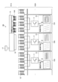
- FIG. 4 is a diagram illustrating a configuration of the linear motor according to the second embodiment.
- the linear motor 2A is a magnet-movable linear motor including a motor drive amplifier 10A and a coil 12 for driving the motor on the track side.
- the linear motor 2A operates by three-phase alternating current.
- FIG. 4 shows a configuration of the linear motor 2A in a state where the three-phase coil 12 used for the power transmission coil and the power receiving coil 14A face each other.
- the linear motor 2A performs non-contact power feeding of an electromagnetic induction method or a magnetic resonance method.
- the linear motor 2A includes one mover 61A and a fixed portion 62A.
- the fixing portion 62A has a plurality of stators 65A described later.
- One stator 65A includes one motor driving amplifier 10A and a three-phase coil 12.
- the three coils 12 are arranged in a straight line.
- a plurality of stators 65A are linearly arranged so that the coils 12 are arranged in a straight line, and the mover 61A linearly moves on the fixed portion 62A by motor driving.
- the coils 12 provided in each stator 65A generate a magnetic field on the mover 61A side.
- the coil 12 has a function of a motor drive coil that drives the mover 61A and a function of a power transmission coil that transmits power to the mover 61A.
- Each motor drive amplifier 10A includes control means 15, one inverter 11, and one power source 80 described later.
- the power supply 80 is not shown.
- FIG. 4 schematically shows the connection between the inverter 11 and the coil 12, and the exact connection will be described later.
- the power supply 80 has a function similar to that of the power supply 32 described in the first embodiment, and outputs a voltage to the inverter 11.
- the inverter 11 has the same function as the inverter 31 described in the first embodiment.
- the control means 15 has the same function as the control means 35 described in the first embodiment.
- the inverter 11 is connected to the three coils 12 in one stator 65A.
- the first inverter 11 is connected to the first to third coils 12, and in the second stator 65A, the second inverter 11 is connected to the fourth to sixth coils.
- the coil 12 is connected.
- the first and fourth coils 12 are U-phase coils to which a U-phase AC voltage is applied, and the second and fifth coils 12 are V-phase coils to which a V-phase AC voltage is applied.
- the sixth coil 12 is a W-phase coil to which a W-phase AC voltage is applied.
- Each inverter 11 is connected to the control means 15 and the power source 80.
- the control means 15 transmits a voltage command similar to that in the first embodiment to the inverter 11.
- the command for outputting the first voltage when performing non-contact power feeding is referred to as the first voltage command
- the command for outputting the second voltage when performing motor driving is the second command. This will be described as a voltage command.
- the first voltage and the second voltage may be different for each embodiment.
- the inverter 11 supplies the first voltage to the coil 12 in accordance with the first voltage command from the control means 15 when performing non-contact power feeding, and the second voltage from the control means 15 when driving the motor.
- the second voltage is supplied to the coil 12 according to the voltage command.
- the coil 12 generates a first magnetic field by the first voltage supplied when performing non-contact power feeding, and generates a second magnetic field by the second voltage supplied when driving the motor.
- the mover 61A is a moving body that is linearly moved by the fixed portion 62A.
- the mover 61A includes a position sensor 17, a magnet 16 that is a permanent magnet, a rectifier 13, and three power receiving coils 14A.
- the magnet 16 generates a magnetic flux on the fixed portion 62A side.
- the bottom surface of the magnet 16 is a surface facing the coil 12.
- the bottom surface shape and bottom surface size of the magnet 16 are substantially the same as the shape and size of the rectangular region in which the three coils 12 are arranged. In other words, the facing surface of the magnet 16 with respect to the coil 12 is substantially the same as the arrangement region of the three coils 12.
- the mover 61A moves along the arrangement direction of the coil 12 on the fixed portion 62A by the thrust generated by the action of the current flowing in the coil 12 included in the fixed portion 62A and the magnetic flux generated from the magnet 16. Since the coils 12 included in the plurality of stators 65 ⁇ / b> A are arranged in a straight line, the mover 61 ⁇ / b> A moves along a linear direction that is an arrangement direction of the coils 12.
- the coil diameter of the receiving coil 14A and the coil diameter of the coil 12 are the same.
- Each power receiving coil 14A included in the mover 61A is disposed in the mover 61A so as to be opposed to the coil 12 included in the stator 65A on a one-to-one basis.
- the magnet 16 and the three power receiving coils 14 ⁇ / b> A are arranged linearly so as to face the six coils 12.
- the first power receiving coil 14A in the power receiving coil 14A is a U-phase coil
- the second power receiving coil 14A is a V-phase coil
- the third power receiving coil 14A is a W-phase coil.
- Each power receiving coil 14 ⁇ / b> A receives the AC power from the fixed portion 62 ⁇ / b> A by receiving the magnetic field generated by the coil 12 included in the fixed portion 62 ⁇ / b> A.
- the linear motor 2A supplies power to the mover 61A in a non-contact manner by electromagnetic induction using the coil 12 as a primary coil and the power receiving coil 14A as a secondary coil.
- the power receiving coil 14 ⁇ / b> A sends the received AC power to the rectifier 13.
- the rectifier 13 is an element that converts AC power from the power receiving coil 14A into DC power.
- the rectifier 13 supplies the converted DC power to a capacitor 18 (to be described later) and to a load such as the position sensor 17.
- the position sensor 17 that is a position detection device is a sensor that detects the position of the mover 61A.
- the position sensor 17 operates using DC power sent through the rectifier 13.
- the position sensor 17 detects the position of the mover 61A in the fixed portion 62A.
- the position sensor 17 transmits position information indicating the position of the mover 61A to each control means 15 by wireless communication.
- the position sensor 17 is an example of an accessory device disposed on the mover 61 ⁇ / b> A, and the accessory device disposed on the mover 61 ⁇ / b> A may be a position detection device other than the position sensor 17.
- the control means 15 determines a voltage command to be transmitted to each stator 65A based on the position information sent from the position sensor 17.
- the control means 15 sends a voltage command to the inverter 11 so that a voltage for driving the motor is supplied to the coil 12 of the stator 65A at the position where the magnet 16 and the coil 12 face each other.
- the control means 15 controls the inverter 11 so that the voltage for driving the motor is supplied to the coil 12 facing the magnet 16 at the timing when the magnet 16 and the coil 12 face each other.
- the control unit 15 sends a voltage command to the inverter 11 so that a non-contact power supply voltage is supplied to the coil 12 of the stator 65A at a position where the power receiving coil 14A and the coil 12 face each other.
- control means 15 controls the inverter 11 so that the contactless power supply voltage is supplied to the coil 12 facing the power receiving coil 14A at the timing when the power receiving coil 14A and the coil 12 face each other.
- the control unit 15 sends a voltage command not to output a voltage to the inverter 11.
- the control means 15 transmits to the inverter 11 any one of a voltage command for non-contact power feeding, a voltage command for driving a motor, and a voltage command that does not output a voltage.
- the control means 15 is configured to provide a voltage command for non-contact power supply or a motor drive even when the magnet 16 and the power receiving coil 14A are not on any of the three coils 12 of the stator 65A.
- a voltage command may be sent to the inverter 11.
- a position detection device other than the position sensor 17 may detect the position information and transmit it to the control means 15. In this case, the mover 61A may not have the position sensor 17.
- a power supply 80 may be connected to each motor drive amplifier 10A, or the power supply 80 may be shared by each motor drive amplifier 10A.
- the motor drive amplifier 10A shares the power source 80 one power source is arranged for the fixed portion 62A, and a voltage is output from the power source to each stator 65A.
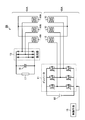
- FIG. 5 is a diagram illustrating a configuration of the non-contact power feeding mechanism of the linear motor according to the second embodiment.
- FIG. 5 shows the circuit configuration of the mover 61A included in the linear motor 2A and the circuit configuration of the stator 65A included in the linear motor 2A.
- one stator 65A among the plurality of stators 65A included in the linear motor 2A is illustrated.
- the illustration of the magnet 16 provided in the mover 61 ⁇ / b> A is omitted.
- the non-contact power feeding mechanism of the linear motor 2A is realized by the mover 61A and the stator 65A.
- the stator 65 ⁇ / b> A includes one inverter 11, three coils 12, a power supply 80, and control means 15.
- the inverter 11 is a three-phase output inverter that uses two sets of switching elements for each of the U-phase, V-phase, and W-phase. Each switching element has a transistor and a diode.
- the three coils 12 include a U-phase coil, a V-phase coil, and a W-phase coil.
- the U-phase coil is connected to the U-phase switching element
- the V-phase coil is connected to the V-phase switching element
- the W-phase coil is connected to the W-phase switching element.
- the coil 12 and the switching element are star-connected.
- the mover 61A includes a rectifier 13, a position sensor 17, and three power receiving coils 14A.
- the rectifier 13 has a total of six diodes including two sets of U phase, V phase, and W phase.
- the three power receiving coils 14A are a U-phase coil, a V-phase coil, and a W-phase coil.
- the U-phase coil is connected to the U-phase diode
- the V-phase coil is connected to the V-phase diode
- the W-phase coil is connected to the W-phase diode.
- the rectifier 13, the capacitor 18, and the position sensor 17 are connected in parallel.
- the AC power received by the power receiving coil 14A from the stator 65A is sent to the rectifier 13 and the rectifier 13 converts it into DC power.
- This DC power is sent to the capacitor 18 and stored in the capacitor 18, and also supplied to the position sensor 17. Power storage in the capacitor 18 may be performed in a state where the mover 61A is stopped.
- the mover 61A may not include the capacitor 18.
- the power receiving coil 14A receives the magnetic field generated by the coil 12 to transmit power in a non-contact manner.
- the mover 61 ⁇ / b> A is moved by the current flowing through the coil 12 and the magnetic flux generated from the magnet 16.
- the linear motor 2A includes the coil 12 that moves the mover 61A to the track side, and the coil 12 is used as a power transmission coil during non-contact power feeding.
- the linear motor 2A can realize non-contact power feeding with the driving coil 12 and the power source 80 without preparing a dedicated coil for non-contact power feeding and a dedicated power source for non-contact power feeding.
- FIG. 6 is a flowchart of an operation procedure of a control unit included in the linear motor according to the second embodiment.
- the position sensor 17 detects position information and transmits it to the control means 15.
- the control means 15 receives position information from the position sensor 17 (step S1), and calculates the positions of the magnet 16 and the power receiving coil 14A based on the position information (step S2). At this time, the control means 15 calculates the positions of the magnet 16 and the power receiving coil 14 ⁇ / b> A with respect to the coil 12.
- control means 15 calculates the voltage command corresponding to the position of the magnet 16 and the receiving coil 14A with respect to its stator 65A (step S3). At this time, the control means 15 determines which magnet 12 is located on which coil 12 in which stator 65A, and the power receiving coil 14A is located on which coil 12 in which stator 65A. Determine whether you are doing. The control means 15 calculates a voltage command to each stator 65A based on which coil 12 the magnet 16 and the power receiving coil 14A are located on. In other words, the control means 15 determines the first voltage command and the second voltage command for each stator 65A based on which coil 12 the magnet 16 and the power receiving coil 14A are located on. Decide which one to send. The control means 15 transmits the calculated voltage command to the inverter 11 (step S4).
- the control means 15 controls the inverter 11 of this stator 65A. A voltage command for driving the motor is transmitted.
- control means 15 is configured such that when at least one coil 12 is directly under the power receiving coil 14A within one stator 65A and none of the coils 12 is directly under the magnet 16, A voltage command for non-contact power supply is transmitted to the inverter 11.
- the control means 15 is a voltage command for setting the voltage to 0 for the inverter 11 of the stator 65A. Is transmitted to the inverter 11.
- the control means 15 determines the voltage when at least one of the three coils 12 is directly under the magnet 16 and when at least one of the three coils 12 is directly under the power receiving coil 14A. Send a voltage command to zero.
- the inverter 11 turns the coil 12 on and off based on the voltage command received from the control means 15.
- the inverter 11 receives the voltage command for driving the motor
- the inverter 11 outputs the voltage for driving the motor and turns on the three coils 12.
- the inverter 11 receives a voltage command for contactless power feeding
- the inverter 11 outputs a voltage for contactless power feeding and turns on the three coils 12.
- the inverter 11 receives a voltage command for setting the voltage to 0, the inverter 11 turns off the three coils 12 without outputting the voltage.
- turning on the coil 12 means turning the coil 12 into an operating state, and indicates a state in which a voltage for driving a motor or a voltage for non-contact power feeding is output from the inverter 11 to the coil 12.
- these voltages include PWM-modulated voltages as described above.
- turning off the coil 12 means a state in which neither the voltage for driving the motor nor the voltage for non-contact power feeding is output from the inverter 11 to the coil 12.
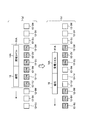
- FIG. 7 is a diagram for explaining the ON / OFF timing of the coil in the linear motor according to the second embodiment.
- the state of the linear motor 2A at the first timing when the mover 61A is moving is indicated by a state (a), and the state of the linear motor 2A at the second timing is indicated by a state (b).
- the coils 12 included in the leftmost stator 65A are indicated by coils 12-0U, 12-0V, and 12-0W in order from the left, and the coil 12 included in the second stator 65A from the left. Are indicated by coils 12-1U, 12-1V, 12-1W in order from the left side.
- the coil 12 included in the third stator 65A from the left is indicated by coils 12-2U, 12-2V, and 12-2W in order from the left, and the coil 12 included in the rightmost stator 65A.
- the coils 12-0U, 12-0V, 12-0W included in the leftmost stator 65A and the coils 12-3U, 12-3V, 12-3W included in the rightmost stator 65A are Is off.
- the coils 12-1U, 12-1V, and 12-1W included in the second stator 65A from the left are turned on by the motor driving voltage.
- the coils 12-2U, 12-2V, and 12-2W included in the third stator 65A from the left are turned on by the non-contact power supply voltage.
- the timing at which the mover 61A moves and a part of the magnet 16 is positioned immediately above the coil 12-0W provided in the leftmost stator 65A is the second timing.
- the magnet 16 has come directly above the rightmost coil 12-0W, and the remaining coils 12- Neither the magnet 16 nor the power receiving coil 14A has moved immediately above 0U, 12-0V.
- the power receiving coil 14A is directly above the rightmost coil 12-1W, and immediately above the remaining coils 12-1U and 12-1V. Magnet 16 is coming.
- the power receiving coil 14A is located immediately above the coils 12-2U and 12-2V, and the magnet is located immediately above the rightmost coil 12-2W. Neither 16 nor the power receiving coil 14A has moved.
- the rightmost stator 65A is after the magnet 16 and the power receiving coil 14A have passed, and the magnet 16 and the power receiving coil 14A are directly above the coils 12-3U, 12-3V, and 12-3W. No.
- the coils 12-0U, 12-0V, and 12-0W included in the leftmost stator 65A are all turned on by the motor driving voltage.
- the coils 12-1U, 12-1V, and 12-1W included in the second stator 65A from the left are off.
- the coils 12-2U, 12-2V, and 12-2W included in the third stator 65A from the left are turned on by the non-contact power supply voltage.
- the coils 12-3U, 12-3V, and 12-3W included in the rightmost stator 65A are off.
- stator 65A turns on the three coils 12 with the non-contact power supply voltage only when the three power receiving coils 14A are moving directly above the three coils 12, and the one or two coils 12 are turned on.
- the power receiving coil 14 ⁇ / b> A is moving immediately above the three coils 12, the three coils 12 may be turned off.
- the bottom surface shape and the bottom surface dimension of the magnet 16 are substantially the same as the region where the three coils 12 are arranged. It is not limited to shape and size.
- the bottom surface shape and the bottom surface dimension of the magnet 16 may be substantially the same as a region where four or more coils 12 are linearly arranged.
- the facing surface of the magnet 16 with respect to the coil 12 may be larger than the arrangement area of the three coils 12.
- the bottom surface shape and the bottom surface dimension of the magnet 16 may be substantially the same as the region where the six coils 12 are linearly arranged.
- the motor 2 ⁇ / b> A can drive the motor using at least three coils 12.
- the mover 61A may include four or more power receiving coils 14A.
- the power receiving coil 14A is linearly arranged in the movable element 61A so that the power receiving coil 14A included in the movable element 61A can face the coil 12 included in the stator 65A on a one-to-one basis.
- the mover 61A may include six power receiving coils 14A.
- the linear motor 2A uses the at least three coils 12 in a non-contact manner regardless of the position of the mover 61A on the stator 65A. Power can be supplied.
- the stator 65A includes the inverter 11 and the control means 15. Based on the positions of the magnet 16 and the power receiving coil 14 ⁇ / b> A, the control unit 15 switches between a voltage command for performing non-contact power feeding and a voltage command for performing motor driving, and transmits them to the inverter 11. Thereby, the inverter 11 switches and outputs the voltage for performing non-contact electric power feeding, and the voltage for performing a motor drive.
- the motor drive amplifier 10A switches and outputs the voltage for driving the motor and the voltage for non-contact power feeding from one inverter 11. Therefore, the linear motor 2A can perform motor driving and non-contact power feeding while suppressing an increase in size of the apparatus.
- Embodiment 3 FIG. Next, a third embodiment of the present invention will be described with reference to FIGS.
- the neutral point of the star connection in the stator is connected to the reference potential of the motor drive amplifier via a switch. This allows single phase operation in the stator.
- FIG. 8 is a diagram illustrating a configuration of a stator included in the linear motor according to the third embodiment.
- constituent elements in FIG. 8 constituent elements that achieve the same functions as those of the stator 65 ⁇ / b> A of the second embodiment shown in FIG. 5 are given the same reference numerals, and redundant descriptions are omitted.
- a linear motor 2B described later includes a stator 65B and a mover 61B described later.
- the linear motor 2B includes a fixed portion including a plurality of stators 65B and control means 15, and the mover 61B moves on the fixed portions.
- the non-contact power feeding mechanism of the linear motor 2B is realized by the mover 61B and the stator 65B.
- the stator 65B includes one inverter 11 and a three-phase coil 12, and the three-phase coil 12 is star-connected.
- the stator 65B includes a switch 19.
- the neutral point 20 of the star connection is connected to the reference potential of the motor drive amplifier via the switch 19. Specifically, the neutral point 20 of the star connection is connected via the switch 19 to the power source 80 provided in the stator 65B. That is, here, the reference potential means a negative potential of the power source 80.
- the control means 15 transmits to the inverter 11 a voltage command for turning on the switching element corresponding to the coil 12 for which an induced electromotive force is to be generated. Specifically, at the time of non-contact power supply, the control unit 15 transmits a voltage command for non-contact power supply for turning on a switching element corresponding to the coil 12 to be subjected to non-contact power supply to the inverter 11.
- the stator 65B turns on the switch 19 in accordance with an instruction from the control means 15 during non-contact power feeding, thereby performing a single-phase operation.
- FIG. 8 shows a current path when the upper U-phase transistor is operated.
- the stator 65B can turn on the coil 12 corresponding to the transistor to be operated by operating a specific transistor included in the inverter 11 with the switch 19 turned on.
- the stator 65B can field the coil 12 for each single phase when the coil 12 is operated as a power transmission coil.
- stator 65B turns off the switch 19 in accordance with an instruction from the control means 15 when driving the motor. As a result, when the motor is driven, all three phases of the inverter 11 are operated.
- the mover 61B since the stator 65B can operate for each single phase during non-contact power feeding, the mover 61B only needs to have one power receiving coil that faces the single-phase coil 12 that performs non-contact power feeding. Thereby, compared with the case where all the three phases operate
- FIG. 9 is a diagram illustrating a schematic configuration of the linear motor according to the third embodiment.
- the linear motor 2B includes a mover 61B and a fixed portion 62B.
- the magnet 16 and the power receiving coil 14B are illustrated among the components included in the mover 61B, and the position sensor 17, the rectifier 13, and the capacitor 18 included in the mover 61B are not illustrated.
- FIG. 9 schematically shows the connection between the switch 19 and the coil 12 and the connection between the motor drive amplifier 10B and the coil 12, and the exact connection is as shown in FIG.
- the mover 61B includes a magnet 16 and one power receiving coil 14B.
- the power receiving coil 14B is a coil similar to the power receiving coil 14A.
- the fixing portion 62B includes a plurality of stators 65B.
- Each stator 65B included in the fixing unit 62B includes a motor drive amplifier 10B, three coils 12, and a switch 19.
- the motor drive amplifier 10 ⁇ / b> B includes an inverter 11, a control unit 15, and a power supply 80.
- the difference between the stator 65B and the stator 65A is that the stator 65B has the switch 19 as described above.
- the switch 19 may be arranged in the motor drive amplifier 10B.
- control means 15 controls the motor drive voltage for turning on the coil 12 with respect to the inverter 11 of the stator 65B. Send a command. At this time, the control means 15 turns off the switch 19.
- the control means 15 is connected to the inverter 11 of the stator 65B. A voltage command for non-contact power supply for turning on the coil 12 immediately below the power receiving coil 14B is transmitted. At this time, the control means 15 turns on the switch 19.
- the control means 15 is directly under the power receiving coil 14B with respect to the inverter 11 of the stator 65B. A voltage command for non-contact power supply for turning on the coil 12 is transmitted.
- control means 15 is a voltage that sets the voltage to 0 with respect to the inverter 11 of the stator 65B. Send a command.
- the inverter 11 turns the coil 12 on and off based on the voltage command received from the control means 15.
- the inverter 11 receives a voltage command for driving the motor
- the inverter 11 outputs a voltage for driving the motor.
- the coil 12 is turned on.
- the inverter 11 receives a voltage command for contactless power feeding
- the inverter 11 outputs a voltage for contactless power feeding to the coil 12 corresponding to the voltage command for contactless power feeding.
- the coil 12 corresponding to the voltage command for non-contact power supply is turned on, and the other coils 12 are turned off.
- the inverter 11 receives a voltage command for setting the voltage to 0, the inverter 11 turns off the three coils 12 without outputting the voltage.
- FIG. 10 is a diagram for explaining the ON and OFF timings of the coil in the linear motor according to the third embodiment.
- the coil 12 shall be arrange
- the coils 12-0U, 12-0V, 12-0W included in the leftmost stator 65B and the coils 12-3U, 12-3V, 12-3W included in the rightmost stator 65B are , Both are off.
- the coils 12-1U, 12-1V, and 12-1W included in the second stator 65B from the left are all turned on by a motor driving voltage.
- the coil 12-2U is turned on by the non-contact power supply voltage, and the coils 12-2V and 12-2W are turned off.
- the timing at which the mover 61B moves and a part of the magnet 16 is positioned immediately above the coil 12-0W provided in the leftmost stator 65B is the second timing.
- the magnet 16 comes directly above the rightmost coil 12-0W, and the remaining coils 12- Neither the magnet 16 nor the power receiving coil 14B has moved immediately above 0U, 12-0V.
- the power receiving coil 14B comes directly above the rightmost coil 12-1W, and immediately above the remaining coils 12-1U and 12-1V. Magnet 16 is coming.
- the third stator 65B and the rightmost stator 65B from the left are after the magnet 16 and the power receiving coil 14B have passed, and the coils 12-2U, 12-2V, 12-2W, 12-3U, Neither the magnet 16 nor the receiving coil 14B is directly above 12-3V, 12-3W.
- the coils 12-0U, 12-0V, and 12-0W included in the leftmost stator 65B are all turned on by the motor driving voltage.
- the coils 12 included in the second stator 65B from the left are turned off, and the coil 12-1W is turned on by the non-contact power supply voltage. Further, the coils 12-2U, 12-2V, 12-2W, 12-3U, 12-3V, and 12-3W included in the third stator 65B from the left and the rightmost stator 65B are all off. is there.
- the stator 65B that drives the motor turns on only the coil 12 directly above the magnet 16 and turns off the remaining coils 12. can do.
- the mover 61B may be provided with one power receiving coil 14B so as to face the single phase of the coil 12. Therefore, the mover 61B can be made small.
- the neutral point 20 of the star connection is connected to the reference potential of the motor drive amplifier 10B via the switch 19, so that the switch 19 is turned on for each single phase.
- the on / off of the coil 12 can be controlled.
- the linear motor 2B only needs to turn on one coil 12 during non-contact power feeding, and only needs to turn on the coil 12 directly above the magnet 16 when driving the motor. Can be suppressed.
- mover 61B should just be provided with the one receiving coil 14B, the needle
- Embodiment 4 FIG. Next, a fourth embodiment of the present invention will be described with reference to FIG.
- contactless power feeding is performed by a magnetic resonance method by disposing capacitors on the stator and the mover.
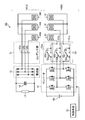
- FIG. 11 is a diagram illustrating a configuration of the non-contact power feeding mechanism of the linear motor according to the fourth embodiment.
- constituent elements in FIG. 11 constituent elements that achieve the same functions as those of the linear motor 2A of the second embodiment shown in FIG.
- FIG. 11 shows a circuit configuration of a mover 61C included in the linear motor 2C and a circuit configuration of a stator 65C included in the linear motor 2C.
- FIG. 11 one stator 65C among the plurality of stators 65C included in the linear motor 2C is illustrated. Further, in FIG. 11, the illustration of the magnet 16 provided in the mover 61C is omitted.
- the linear motor 2C transmits power in a non-contact manner when the power receiving coil 14A receives the magnetic field generated by the coil 12, similarly to the linear motor 2A. Similarly to the linear motor 2A, the linear motor 2C moves the mover 61C by the current flowing through the coil 12 and the magnetic flux generated from the magnet 16.
- the non-contact power feeding mechanism of the linear motor 2C is realized by the mover 61C and the stator 65C.
- the difference between the mover 61C and the mover 61A is that the mover 61C includes a capacitor group 21 between the position sensor 17 as a load and the power receiving coil 14A.
- capacitor group 21 is connected between rectifier 13 and power receiving coil 14A.
- the capacitor group 21 includes three capacitors 22a, 22b, and 22c that are power receiving capacitors.
- the mover 61C includes the three power receiving coils 14A in the same manner as the mover 61A.
- the capacitor group 21 is arranged on a connection line connecting the power receiving coil 14 ⁇ / b> A and the rectifier 13. That is, in the mover 61C, one capacitor is disposed on one connection line between the power receiving coil 14A and the rectifier 13.
- the capacitor 22a is disposed on the first connection line to which the first power receiving coil 14A is connected
- the capacitor 22b is disposed on the second connection line to which the second power receiving coil 14A is connected.
- the capacitor 22c is disposed on the third connection line to which the third power receiving coil 14A is connected.
- the capacitor 22a is connected in series with the first power receiving coil 14A
- the capacitor 22b is connected in series with the second power receiving coil 14A
- the capacitor 22c is connected in series with the third power receiving coil 14A. Is connected.
- stator 65C includes a switching mechanism 55 between the motor driving amplifier including the inverter 11 and the coil 12.
- the switching mechanism 55 includes three switching units 51a, 51b, and 51c.
- the switching unit 51a includes a capacitor 52a and a switch 53a
- the switching unit 51b includes a capacitor 52b and a switch 53b
- the switching unit 51c includes a capacitor 52c and a switch 53c.
- Capacitors 52a, 52b, and 52c that are power transmission capacitors are used when the coil 12 is a power transmission coil.
- the switching mechanism 55 is connected in series to the inverter 11 and the coil 12 between the inverter 11 and the coil 12.
- a switching unit 51 a is connected to the first coil 12
- a switching unit 51 b is connected to the second coil 12
- a switching unit 51 c is connected to the third coil 12.
- the capacitor 52a and the switch 53a are connected in series
- the capacitor 52b and the switch 53b are connected in series
- the switching unit 51c the capacitor 52c and the switch 53c are connected in series.
- the switching mechanism 55 may be disposed in the motor drive amplifier provided in the stator 65C, or may be disposed outside the motor drive amplifier.
- the switch 53a switches whether the path between the inverter 11 and the first coil 12 is a path via the capacitor 52a or a path not via the capacitor 52a.
- the switch 53b switches whether the path between the inverter 11 and the second coil 12 is a path via the capacitor 52b or a path not via the capacitor 52b.
- the switch 53c switches whether the path between the inverter 11 and the third coil 12 is a path via the capacitor 52c or a path not via the capacitor 52c.
- the path through the capacitor 52a and the path not through the capacitor 52a are connected in parallel, and the switch 53a switches between these paths.
- a path via the capacitor 52b and a path not via the capacitor 52b are connected in parallel, and the switch 53b switches between these paths.
- the path via the capacitor 52c and the path not via the capacitor 52c are connected in parallel, and the switch 53c switches between these paths.
- the switches 53a to 53c are controlled by the control means 15 connected to the stator 65C.
- the switching mechanism 55 forms a path that does not pass through the capacitors 52a to 52c by the switches 53a to 53c when the motor is driven, and forms a path that passes through the capacitors 52a to 52c by the switches 53a to 53c during non-contact power feeding. In this way, the switching mechanism 55 switches the path between the inverter 11 and the coil 12 when the motor is driven and when contactless power feeding is performed.
- the capacitors 22a to 22c and the three power receiving coils 14A form a first LC resonance circuit that is a first resonance circuit.
- the capacitors 52a to 52c and the three coils 12 form a second LC resonance circuit that is a second resonance circuit.
- the stator 65C and the mover 61C are prepared so that the LC resonance frequency of the stator 65C and the LC resonance frequency of the mover 61C are the same.
- the motor drive amplifier provided in the linear motor 2C operates in accordance with the LC resonance frequency of the LC resonance circuit during non-contact power feeding. As described above, the linear motor 2C can perform non-contact power feeding by the magnetic resonance method by operating the motor drive amplifier at the same frequency as the LC resonance frequency of the coil 12 and the capacitors 52a to 52c.
- the magnetic resonance type non-contact power feeding performed by the linear motor 2C uses LC resonance, and thus is resistant to positional displacement between the coil 12 and the power receiving coil 14A.
- the electromagnetic induction type non-contact power supply allows a positional deviation of 1/10 or less of the coil diameter, whereas the magnetic resonance type non-contact power supply performed by the linear motor 2C is up to a half of the coil diameter.
- a positional deviation between the coil 12 and the power receiving coil 14A can be allowed. For example, when the coil diameters of the coil 12 and the power receiving coil 14A are 10 cm, the allowable displacement is 1 cm in the electromagnetic induction method, whereas the allowable displacement is 5 cm in the non-contact power supply method.
- the linear motor 2 ⁇ / b> C performs magnetic resonance with the coil 12 used for motor driving and the power source 80 used for motor driving without preparing a dedicated coil for non-contact power feeding and a dedicated power source for non-contact power feeding.
- System non-contact power supply can be realized.
- the capacitor group 21 is disposed on the movable element 61C, and the switching mechanism 55 including the capacitors 52a to 52c and the switches 53a to 53c is disposed on the stator 65C.
- the linear motor 2 ⁇ / b> C can realize magnetic resonance type non-contact power feeding with the driving coil 12 and the power source 80.
- Embodiment 5 a fifth embodiment of the present invention will be described with reference to FIG.
- a capacitor is provided on the connection line between the switch 19 and the coil 12 with respect to the stator described in the third embodiment.
- the neutral point 20 of the star-connected coil 12 is connected to the reference potential of the motor drive amplifier via the switch 19 and the capacitor.
- FIG. 12 is a diagram illustrating a configuration of a stator included in the linear motor according to the fifth embodiment.
- constituent elements that achieve the same functions as those of the stator 65 ⁇ / b> B of the third embodiment shown in FIG. 8 are assigned the same reference numerals, and redundant descriptions are omitted.
- the linear motor of the fifth embodiment includes the stator 65D and the mover 61C described in the fourth embodiment.
- the linear motor of the fifth embodiment has a fixed portion having a plurality of stators 65D, and the mover 61C moves on this fixed portion.
- stator 65D has a capacitor 25 between the switch 19 and the coil 12.
- stator 65D includes one switch 19 and one capacitor 25.
- the stator 65C in the fourth embodiment has the three switching units 51a, 51b, and 51c.
- the stator 65D in the present embodiment has one switching unit including the switch 19 and the capacitor 25. It has only 51d. That is, in this embodiment, the capacitor 25 is provided as a power transmission capacitor.
- the neutral point 20 of the star connection is connected to the reference potential of the motor drive amplifier via the switch 19 and the capacitor 25.
- the capacitor 25 is disposed on the connection line between the neutral point 20 and the switch 19. That is, the neutral point 20 of the star connection is connected to the capacitor 25 included in the stator 65D, and the capacitor 25 is connected to the power source 80 connected to the stator 65D via the switch 19.
- the stator 65D turns on the switch 19 in accordance with an instruction from the control means 15 during non-contact power feeding, thereby performing a single phase operation.
- the stator 65D can turn on the phase corresponding to the transistor to be operated by operating a specific transistor included in the inverter 11 with the switch 19 turned on.
- the stator 65D can field the coil 12 for each single phase when the coil 12 is operated as a power transmission coil.
- the stator 65D turns off the switch 19 according to an instruction from the control means 15 when driving the motor. As a result, when the motor is driven, all three phases of the inverter 11 are operated.
- stator 65D forms a path that does not pass through the capacitor 25 by turning off the switch 19 when the motor is driven, and forms a path that passes through the capacitor 25 by turning on the switch 19 during non-contact power feeding. To do.
- stator 65D switches the path between the inverter 11 and the coil 12 when the motor is driven and when contactless power feeding is performed.
- the capacitors 22a to 22c and the three power receiving coils 14A form a first LC resonance circuit that is a first resonance circuit.
- a second LC resonance circuit which is a second resonance circuit, is formed by the capacitor 25 and the specific coil 12 to which a voltage is supplied during non-contact power feeding.
- the stator 65D and the mover 61C are prepared so that the LC resonance frequency of the stator 65D matches the LC resonance frequency of the mover 61C.
- the motor drive amplifier provided in the linear motor according to the fifth embodiment operates in accordance with the LC resonance frequency of the LC resonance circuit during non-contact power feeding.
- the linear motor according to the fifth embodiment can perform non-contact power feeding by the magnetic resonance method by operating the motor drive amplifier at the same frequency as the LC resonance frequency of the coil 12 and the capacitor 25.
- the mover 61C moving on the stator 65D has one power receiving coil facing the single-phase coil 12 that performs non-contact power feeding. 14A is sufficient. That is, the mover 61C only needs to have one power receiving coil 14A. Thereby, compared with the case where all three phases operate
- the stator 65D has a simple configuration.
- the neutral point 20 of the star connection is connected to the reference potential of the motor drive amplifier via the switch 19 and the capacitor 25, so that the third embodiment and the fourth embodiment Has the same effect. That is, magnetic resonance type non-contact power feeding can be realized for each phase with a simple configuration.
- Embodiment 6 of the present invention will be described with reference to FIG.
- a material for forming the switching element of the inverter 11 will be described.
- Silicon (Si) silicon is generally used as a material for forming the switching element, but silicon carbide (SiC), which is an example of a wide band gap semiconductor, is used for the inverter 11 described in the first to fifth embodiments. May be.
- An SiC element is an example of a semiconductor called a wide bandgap semiconductor, capturing the characteristic that the band gap is larger than that of an Si element.
- a semiconductor formed using a gallium nitride (GaN) -based material or diamond belongs to a wide band gap semiconductor, and these characteristics are also similar to SiC. Therefore, a configuration using a wide band gap semiconductor other than SiC for the switching element also forms the gist of the present invention.
- ⁇ Motor drive amplifiers may generate heat when the voltage output frequency is increased in order to efficiently perform non-contact power feeding and the motor drive amplifier loss increases.
- the motor drive amplifier becomes large. Therefore, in the sixth embodiment, by using a wide band gap semiconductor for the switching element of the inverter 11, an increase in the loss of the motor drive amplifier can be suppressed to half or less.
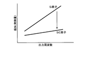
- FIG. 13 is a diagram showing the relationship between the output frequency and the loss in the drive amplifier.
- the horizontal axis of the graph shown in FIG. 13 is the output frequency of the voltage output by the motor drive amplifier when contactless power feeding is performed, and the vertical axis is the loss in the motor drive amplifier when contactless power feeding is performed.
- the loss in the motor drive amplifier will be described as the heat generation amount.
- the switching element when the switching element is a Si element, the amount of heat generation increases rapidly as the output frequency increases.
- the switching element is a SiC element, the amount of generated heat increases only slowly even when the output frequency increases.
- the amount of increase in the amount of heat generated with respect to the output frequency is smaller when the switching element is a SiC element than when the switching element is a Si element.
- the non-contact power supply and the motor drive can be efficiently performed with the inverter 11 having a small configuration.
- FIG. 14 is a diagram of a hardware configuration example of the control unit according to the first to sixth embodiments.
- the control means 15 can be realized by the control circuit 300 shown in FIG. 14, that is, the processor 301 and the memory 302.
- the processor 301 are a CPU (Central Processing Unit, a central processing unit, a processing unit, an arithmetic unit, a microprocessor, a processor, and a DSP) or a system LSI (Large Scale Integration).
- An example of the memory 302 is a RAM (Random Access Memory) or a ROM (Read Only Memory).
- the control means 15 is realized by the processor 301 reading out and executing a program stored in the memory 302 for executing the operation of the control means 15. It can also be said that this program causes a computer to execute the procedure or method of the control means 15.
- the memory 302 is also used as a temporary memory when the processor 301 executes various processes.
- the program executed by the processor 301 may be realized by a computer program product that is a recording medium in which the program is stored.
- An example of the recording medium in this case is a non-transitory computer-readable medium in which a program is stored.
- part of the function of the control means 15 may be realized by dedicated hardware, and part of it may be realized by software or firmware. Embodiments 2 to 6 may be combined. Further, the number of power receiving coils 14A and 14B is not limited to the number described in the second to fifth embodiments, and an arbitrary number may be arranged. Further, the power receiving coil 14A may be disposed at a plurality of locations. For example, the first power receiving coil 14 ⁇ / b> A may be disposed in front of the traveling direction of the magnet 16, and the second power receiving coil 14 ⁇ / b> A may be disposed behind the traveling direction of the magnet 16.
- the configuration described in the above embodiment shows an example of the contents of the present invention, and can be combined with another known technique, and can be combined with other configurations without departing from the gist of the present invention. It is also possible to omit or change the part.
- 1 motor drive system 2A to 2C linear motor, 10, 10A, 10B motor drive amplifier, 11, 31 inverter, 12 coils, 13 rectifiers, 14A, 14B, 41a receiving coil, 15, 35 control means, 16 magnets, 17 positions Sensor, 18, 22a, 22b, 22c, 25, 52a, 52b, 52c capacitor, 19, 30, 53a, 53b, 53c switch, 20 neutral point, 21 capacitor group, 32, 80 power supply, 40 power supply mechanism, 41b power transmission Coil, 50 motor, 51B, 52B voltage, 51a, 51b, 51c, 51d switching part, 55 switching mechanism, 61A, 61B, 61C mover, 62A, 62B fixing part, 65A, 65B, 65C, 65D stator, 71A, 72A voltage command, 300 control times , 301 processor, 302 memory.
Landscapes
- Engineering & Computer Science (AREA)
- Power Engineering (AREA)
- Control Of Ac Motors In General (AREA)
- Control Of Linear Motors (AREA)
- Current-Collector Devices For Electrically Propelled Vehicles (AREA)
- Linear Motors (AREA)
Abstract
モータ駆動システムにおいて、第1の電圧と第2の電圧とを切換えて出力するインバータ(31)と、第1の電圧を出力させるための第1の電圧指令(71A)と、第2の電圧を出力させるための第2の電圧指令(72A)との何れかをインバータ(31)に送信する制御手段(35)と、を有するモータ駆動アンプ(10)と、送電コイルおよび受電コイルを有し、インバータ(31)から出力される第1の電圧によって送電コイル側から受電コイル側に非接触で電力を伝送する給電機構と、固定子および可動子を有し、インバータ(31)から出力される第2の電圧によって固定子が発生させる磁界で可動子を駆動するモータと、を備える。
Description
本発明は、非接触給電を行うことができるモータ駆動システムに関する。
産業界においては非接触給電の技術が一般的に用いられている。この非接触給電の技術は、固定子の上を可動子が移動するリニアモータの可動子への電力供給、センサまたはAGV(Automated Guided Vehicle、無人搬送機)等への電力供給のために用いられる。また、産業界においてモータ駆動アンプは、電気エネルギーを機械エネルギーに変換するために広く一般的に用いられ、リニアモータまたはその他のモータと併せてモータ駆動システムを構成する。さらに、センサまたはAGV等は、モータが搭載されるシステムとともに用いられている。
特許文献1には、可動子の二次側コイルが固定子の一次側コイルと向き合って配置され、可動子とともに二次側コイルが一次側コイルに沿って移動する間に、一次側コイルおよび二次側コイルを用いた電磁誘導によって非接触で可動子に給電する非接触給電装置の技術が開示されている。
しかしながら、上記従来の技術である特許文献1では、複数の固定子のそれぞれに、可動子に給電するためのインバータと、自走式台車を走行させるために電気エネルギーを機械エネルギーに変換するモータ駆動アンプ用のインバータが必要になる。ここで、モータ駆動アンプとはモータ駆動する機能を備えた電力変換装置のことであり、インバータとは直流を交流に変換する回路である。このため、非接触給電装置とモータ駆動アンプそれぞれがインバータを備えるため、装置全体として大型化してしまうという問題があった。
本発明は、上記に鑑みてなされたものであって、装置の大型化を抑制して非接触給電とモータ駆動を行うことができるモータ駆動システムを得ることを目的とする。
上述した課題を解決し、目的を達成するために、本発明のモータ駆動システムは、第1の電圧と第2の電圧とを切換えて出力するインバータと、第1の電圧を出力させるための第1の電圧指令と、第2の電圧を出力させるための第2の電圧指令との何れかをインバータに送信する制御手段と、を有するモータ駆動アンプと、送電コイルおよび受電コイルを有し、インバータから出力される第1の電圧によって送電コイル側から受電コイル側に非接触で電力を伝送する給電機構と、固定子および可動子を有し、インバータから出力される第2の電圧によって固定子が発生させる磁界で可動子を駆動するモータと、を備える。
本発明にかかるモータ駆動システムは、装置の大型化を抑制してモータ駆動と非接触給電とを行うことができるという効果を奏する。
以下に、本発明の実施の形態にかかるモータ駆動システムを図面に基づいて詳細に説明する。なお、この実施の形態によりこの発明が限定されるものではない。
実施の形態1.
図1は、本発明の実施の形態1にかかるモータ駆動システムの構成を示す図である。モータ駆動システム1は、電圧を出力するモータ駆動アンプ10と、モータ駆動アンプ10に接続されるスイッチ30とを備えている。また、モータ駆動システム1は、スイッチ30を介してモータ駆動アンプ10に接続可能な給電機構40と、スイッチ30を介してモータ駆動アンプ10に接続可能なモータ50とを備えている。
図1は、本発明の実施の形態1にかかるモータ駆動システムの構成を示す図である。モータ駆動システム1は、電圧を出力するモータ駆動アンプ10と、モータ駆動アンプ10に接続されるスイッチ30とを備えている。また、モータ駆動システム1は、スイッチ30を介してモータ駆動アンプ10に接続可能な給電機構40と、スイッチ30を介してモータ駆動アンプ10に接続可能なモータ50とを備えている。
モータ駆動システム1は、給電機構40内で非接触給電を行うことと、モータ50を駆動することとを切換えることができる。モータ駆動アンプ10は、第1の電圧を給電機構40に出力し、第2の電圧をモータ50に出力する。モータ駆動アンプ10は、第1の電圧を出力するための後述する電圧指令71Aと、第2の電圧を出力するための後述する電圧指令72Aと、を切換える後述の制御手段35を有している。
給電機構40は、スイッチ30を介してモータ駆動アンプ10に接続可能なよう構成されており、送電コイル41bと受電コイル41aとを有している。給電機構40は、スイッチ30を介してモータ駆動アンプ10に接続されるとモータ駆動アンプ10からの第1の電圧によって送電コイル41bに磁界を発生させる。給電機構40は、送電コイル41bが発生させる磁界を受電コイル41aに与えることで送電コイル41b側から受電コイル41a側に非接触で電力を伝送する。
モータ50は、モータ駆動アンプ10に接続可能なよう構成されており、固定子および可動子を有している。モータ50は、モータ駆動アンプ10に接続されるとモータ駆動アンプ10からの第2の電圧によって固定子が可動子を駆動させる。
なお、モータ駆動システム1は、スイッチ30を備えていなくてもよい。この場合、モータ駆動システム1の使用者によってモータ駆動アンプ10と給電機構40との接続、またはモータ駆動アンプ10とモータ50との接続が行われる。
このように、モータ駆動アンプ10は、モータ50を駆動するモータ駆動機能と、送電コイル41b側から受電コイル41a側に非接触で電力を伝送する非接触給電機能と、を備えている。モータ駆動アンプ10は、給電機構40に接続される場合には第1の電圧を出力し、モータ50に接続される場合には第2の電圧を出力する。
ここで、モータ駆動アンプ10の構成について説明する。図2は、実施の形態1にかかるモータ駆動アンプの構成を示す図である。モータ駆動アンプ10は、電圧を出力する電源32と、電源32から出力された電圧の周波数および振幅の大きさを変えるインバータ31と、インバータ31を制御するマイクロコンピュータである制御手段35とを備えている。電源32が、モータ駆動アンプ10の外部に配置され、外部からモータ駆動アンプ10へ電圧を供給してもよい。
電源32は、直流電源であり、電圧をインバータ31に出力する。なお、電源32は、交流電源であってもよい。この場合、電源32とインバータ31との間にコンバータが接続される。制御手段35は、CPU(Central Processing Unit)といったプロセッサ、およびメモリを有した半導体チップ等である。制御手段35は、インバータ31への電圧指令71A,72Aを切換えることによって、モータ駆動機能と非接触給電機能とを切換える。制御手段35は、非接触給電機能を実行させる場合には、第1の電圧指令である電圧指令71Aをインバータ31に送信し、モータ駆動機能を実行させる場合には、第2の電圧指令である電圧指令72Aをインバータ31に送信する。電圧指令71A,72Aは、出力させたい電圧の、周波数および振幅を示す指令である。インバータ31は、電圧指令71Aを受信すると第1の電圧を出力し、電圧指令72Aを受信すると第2の電圧を出力する。
図3は、実施の形態1にかかるモータ駆動アンプの動作を説明するための図である。モータ駆動システム1では、スイッチ30が操作されることによって、モータ駆動アンプ10が、給電機構40またはモータ50に接続される。スイッチ30への操作は、モータ駆動アンプ10に接続されてモータ駆動アンプ10を制御するPLC(Programmable Logic Controller)といった外部装置が行ってもよいし、使用者が手動で行ってもよい。
モータ駆動アンプ10が給電機構40に接続された場合、モータ駆動アンプ10の制御手段35は、給電機構40への電力供給に用いる電圧の出力を指示する電圧指令71Aをインバータ31に送信する。制御手段35がインバータ31に出力する電圧指令71Aは、出力電圧の周波数を、例えば70kHzから数MHzとさせるための指令である。
また、モータ駆動アンプ10がモータ50に接続された場合、モータ駆動アンプ10の制御手段35は、モータ50への電力供給に用いる電圧の出力を指示する電圧指令72Aをインバータ31に送信する。制御手段35がインバータ31に出力する電圧指令72Aは、出力電圧の周波数を、例えばモータ回転周波数である数百HzおよびPWM(Pulse Width Modulation)(パルス幅変調)周波数である2kHzから20kHzとさせるための指令である。PWM方式は、パルス信号の幅を変える変調方式である。
インバータ31は、制御手段35から電圧指令71Aを受信すると、電圧指令71Aに対応する電圧51Bをスイッチ30側へ出力する。また、インバータ31は、制御手段35から電圧指令72Aを受信すると、電圧指令72Aに対応する電圧52Bをスイッチ30側へ出力する。インバータ31が出力する電圧51B,52Bは、交流電圧である。
モータ駆動アンプ10が給電機構40に接続された場合、インバータ31は、給電機構40に対応する電圧51Bを、スイッチ30を介して給電機構40に出力する。また、モータ駆動アンプ10がモータ50に接続された場合、インバータ31は、モータ50に対応する電圧52Bを、スイッチ30を介してモータ50に出力する。第1の電圧である電圧51Bは、第2の電圧である電圧52Bよりも周波数が高い電圧である。このように、モータ駆動アンプ10は、給電機構40に接続された場合には、モータ50に接続された場合よりも高い周波数の電圧を出力し、モータ50に接続された場合には、給電機構40に接続された場合よりも低い周波数の電圧を出力する。
モータ駆動アンプ10が給電機構40に接続された場合にモータ駆動アンプ10が出力する電圧51Bの周波数の一例は、数MHzであり、モータ駆動アンプ10がモータ50に接続された場合にモータ駆動アンプ10が出力する電圧52Bの周波数の一例は、10kHzである。このように、モータ駆動機能と非接触給電機能とでは、供給される電圧の出力周波数が異なる。周波数が異なる理由は、非接触給電では送受信アンテナであるコイルの位置ずれがあるため、モータ駆動よりもコイルのインダクタンスが小さくなるからである。そのため、出力電力を得るためには電流または周波数が高くされる。しかし、電流を増大させるとコイルの銅損が発生し、エネルギー交換効率が悪化してしまう。そのため、非接触給電では、モータ駆動よりも周波数を高くすることが有効である。
このように、モータ駆動システム1は、モータ50への接続と給電機構40への接続とをスイッチ30で切換えることができるとともに、モータ50への電力供給と給電機構40への電力供給とをモータ駆動アンプ10の制御手段35で切換えることができる。このように、モータ駆動システム1は、1つのモータ駆動アンプ10にて、モータ駆動機能と非接触給電機能とを切換えることができる。すなわち、モータ駆動システム1は、1つのインバータ31でモータ駆動機能および非接触給電機能のそれぞれに適した周波数の電圧を供給することができる。
ここで、一般的にモータ駆動アンプから出力される電圧の出力周波数は、主に出力電力によって制約される。その理由は、大電力で出力周波数を高くした場合、インバータのスイッチング素子の損失が増大し発熱するためである。実施の形態1のモータ駆動アンプ10は、モータ50よりも低電力で動作可能なセンサ等に非接触給電で電力を供給する。例えば、モータ50に必要な電力が1kW程度であるのに対して、センサに必要な電力は1W程度である。このように、センサ等に供給する電力はモータ50に供給する電力よりも低くても良いので、モータ駆動アンプ10は、給電機構40に供給する電圧の出力周波数をモータ50に供給する電圧の出力周波数よりも高くすることが可能である。
なお、本実施の形態におけるセンサとしては、位置センサまたは近接センサが挙げられるが、本実施の形態におけるセンサは、例えば産業(Factory Automation)分野で用いられるセンサであれば何れのセンサであってもよい。
モータ駆動システム1は、非接触給電時に高い周波数の電圧を供給することができるので、給電機構40が備える送電コイル41bと受電コイル41aとの間のエネルギー変換効率を向上させることができる。
このように、モータ駆動アンプ10は、1つの電源32と、1つのインバータ31とを用いて、モータ駆動機能と非接触給電機能とを実現することができる。このため、モータ駆動システム1は、新たに非接触給電専用の電源を準備する必要がない。
比較例としてリニアモータの推力発生用の電磁束を流用する例を考える。モータ駆動機能と非接触給電機能とを有した比較例のモータ駆動システムは、非接触給電用に受け渡される電磁エネルギーに、推力発生用の電磁束を流用する。この場合、モータ駆動用の電磁束は、非接触給電用に比べて周波数が低く、出力電力を大きく取ることができない。もしくは出力電力を大きくとるために、電流が増大しエネルギー変換効率が低下するといった問題がある。すなわち、この比較例のモータ駆動システムでは、非接触給電用に受け渡される電圧が、推力発生用に最適化された電圧であるので、非接触給電用に受け渡される電圧として最適な周波数ではない。エネルギー変換効率良く非接触給電をするためには、非接触給電用の高周波電源を別途用意する必要があり、システムサイズが大型化してしまう。
一方、実施の形態1のモータ駆動システム1は、制御手段35がインバータ31への電圧指令71A,72Aを切換えることによってモータ駆動機能と非接触給電機能とを切換えるので、小さなシステム構成でモータ駆動および非接触給電を実現することができる。
このように実施の形態1によれば、モータ駆動アンプ10は、インバータ31と制御手段35とを備えている。そして、制御手段35が、非接触給電を行うための電圧51Bを出力するための電圧指令71Aと、モータ駆動を行うための電圧52Bを出力するための電圧指令72Aと、の何れかをインバータ31に送信している。これにより、インバータ31が、電圧51Bと電圧52Bとを切換えて出力している。換言すると、モータ駆動アンプ10は、1つのインバータ31が制御手段35からの指令に従って、モータ駆動用の電圧52Bと非接触給電用の電圧51Bとを切換えて出力する。したがって、モータ駆動システム1は、装置の大型化を抑制してモータ駆動と非接触給電とを行うことが可能となる。
さらに、モータ50は、リニアモータまたは回転モータの何れであってもよいので、モータ駆動システム1は、非接触給電が必要な種々の現場において、モータ50を駆動可能なモータ駆動アンプ10を非接触給電用のアンプとして代用することができる。
また、本実施の形態では、エネルギー変換効率よく非接触給電を実現できるので、非接触給電用の送電コイル41bおよび受電コイル41aのサイズの大型化を抑制する効果も得られる。すなわち、非接触給電時に電圧の高周波化が可能となるため、コアを小型化することができ、システムサイズの小型化につながる。
なお、実施の形態1では、インバータ31から出力される電圧がモータ駆動用の電圧52Bの場合、非接触給電機能は停止し、インバータ31から出力される電圧が非接触給電用の電圧51Bの場合、モータ駆動機能は停止するので、モータ駆動アンプ10は、非接触給電とモータ駆動とを交互に行うようなシステムに適用される。
実施の形態2.
つぎに、図4から図7を用いてこの発明の実施の形態2について説明する。実施の形態2では、可動子にモータ駆動用の磁石と非接触給電用の受電コイルとを配置しておき、モータ駆動アンプが、1つのインバータから、モータ駆動用の電圧と非接触給電用の電圧とを切換えて出力する。すなわち、本実施の形態では可動子が受電コイルを備え、固定子が送電コイルを備える。つまり、モータを駆動する駆動コイルとして、送電コイルを用いる。
つぎに、図4から図7を用いてこの発明の実施の形態2について説明する。実施の形態2では、可動子にモータ駆動用の磁石と非接触給電用の受電コイルとを配置しておき、モータ駆動アンプが、1つのインバータから、モータ駆動用の電圧と非接触給電用の電圧とを切換えて出力する。すなわち、本実施の形態では可動子が受電コイルを備え、固定子が送電コイルを備える。つまり、モータを駆動する駆動コイルとして、送電コイルを用いる。
図4は、実施の形態2にかかるリニアモータの構成を示す図である。リニアモータ2Aは、軌道側にモータを駆動するためのモータ駆動アンプ10Aおよびコイル12を備えた磁石可動型のリニアモータである。リニアモータ2Aは、3相交流によって動作する。図4では、送電コイルに用いられる3相のコイル12と、受電コイル14Aと、が対向した状態でのリニアモータ2Aの構成を示している。リニアモータ2Aは、電磁誘導方式または磁気共鳴方式の非接触給電を行う。リニアモータ2Aは、1つの可動子61Aと、固定部62Aとを備えている。
固定部62Aは、後述する複数の固定子65Aを有している。1つの固定子65Aは、1つのモータ駆動アンプ10Aと、3相のコイル12とを含んで構成されている。各固定子65Aでは、3つのコイル12が直線状に並ぶよう配置されている。また、固定部62Aでは、各コイル12が直線状に並ぶよう、複数の固定子65Aが直線状に配置されており、モータ駆動によって可動子61Aが固定部62A上を直線移動する。
各固定子65Aが備えるコイル12は、可動子61A側に磁界を発生させる。コイル12は、可動子61Aを駆動するモータ駆動コイルの機能と、可動子61Aに送電する送電コイルの機能とを有している。
各モータ駆動アンプ10Aは、制御手段15と、1つのインバータ11と、後述する1つの電源80とを備えている。なお、図4では、電源80の図示を省略している。また、図4では、インバータ11とコイル12との接続を模式的に図示しており、正確な接続は後述する。電源80は、実施の形態1で説明した電源32と同様の機能を有しており、インバータ11に電圧を出力する。また、インバータ11は、実施の形態1で説明したインバータ31と同様の機能を有している。また、制御手段15は、実施の形態1で説明した制御手段35と同様の機能を有している。
1つの固定子65A内では、インバータ11が、3つのコイル12に接続されている。例えば、第1の固定子65A内では、第1のインバータ11が第1から第3のコイル12に接続され、第2の固定子65A内では、第2のインバータ11が第4から第6のコイル12に接続されている。第1および第4のコイル12は、U相交流電圧が印加されるU相コイルであり、第2および第5のコイル12は、V相交流電圧が印加されるV相コイルであり、第3および第6のコイル12は、W相交流電圧が印加されるW相コイルである。また、各インバータ11は、制御手段15および電源80に接続されている。
各固定子65Aでは、制御手段15が実施の形態1と同様の電圧指令をインバータ11に送信する。以下の説明では、非接触給電を行う際に第1の電圧を出力させるための指令を第1の電圧指令とし、モータ駆動を行う際に第2の電圧を出力させるための指令を第2の電圧指令として説明する。第1の電圧および第2の電圧は、実施の形態毎に異なってもよい。
インバータ11は、非接触給電を行う際には、制御手段15からの第1の電圧指令に従って第1の電圧をコイル12に供給し、モータ駆動を行う際には、制御手段15からの第2の電圧指令に従って第2の電圧をコイル12に供給する。これにより、コイル12は、非接触給電を行う際に供給される第1の電圧によって第1の磁界を発生させ、モータ駆動を行う際に供給される第2の電圧によって第2の磁界を発生させる。
可動子61Aは、固定部62Aによって直線運動させられる移動体である。ここでは、1つの可動子61Aの底面が、固定子65Aの2つ分の底面と同じ大きさを有している場合について説明する。可動子61Aは、位置センサ17と、永久磁石である磁石16と、整流器13と、3つの受電コイル14Aとを備えている。
磁石16は、固定部62A側に磁束を発生させる。磁石16の底面は、コイル12に対向する面である。磁石16の底面形状および底面寸法は、3つ分のコイル12が配置された矩形領域の形状および寸法と略同じである。換言すると、磁石16のコイル12に対する対向面は、コイル12の3つ分の配置領域と略同じである。
可動子61Aは、固定部62Aが備えるコイル12に流れる電流と、磁石16から発生する磁束との作用によって発生する推力で固定部62A上をコイル12の配置方向に沿って移動する。複数の固定子65Aが備える各コイル12は、直線状に並べられているので、可動子61Aは、コイル12の配置方向である直線方向に沿って移動する。
受電コイル14Aのコイル径と、コイル12のコイル径とは同じである。可動子61Aが備える各受電コイル14Aは、固定子65Aが備えるコイル12に1対1で対向できるよう可動子61A内に配置されている。可動子61Aでは、磁石16および3つの受電コイル14Aが、6つのコイル12に対向するよう直線状に配置されている。
受電コイル14Aのうちの第1の受電コイル14Aは、U相コイルであり、第2の受電コイル14Aは、V相コイルであり、第3の受電コイル14Aは、W相コイルである。各受電コイル14Aは、固定部62Aが備えるコイル12が発生させる磁界を受け取ることによって、固定部62Aからの交流電力を受電する。このように、リニアモータ2Aは、一次コイルであるコイル12および二次コイルである受電コイル14Aを用いた電磁誘導によって非接触で可動子61Aに給電を行う。受電コイル14Aは、受電した交流電力を整流器13に送る。
整流器13は、受電コイル14Aからの交流電力を直流電力に変換する素子である。整流器13は、変換した直流電力を後述するコンデンサ18に供給するとともに、位置センサ17といった負荷に供給する。
位置検出装置である位置センサ17は、可動子61Aの位置を検出するセンサである。位置センサ17は、整流器13を介して送られてくる直流電力を用いて動作する。位置センサ17は、可動子61Aが固定部62A内の何れの位置にあるかを検出する。位置センサ17は、可動子61Aの位置を示す位置情報を、無線通信によって各制御手段15に送信する。なお、位置センサ17は、可動子61Aに配置される付帯装置の一例であり、可動子61Aに配置される付帯装置は位置センサ17以外の位置検出装置であってもよい。
制御手段15は、位置センサ17から送られてくる位置情報に基づいて、各固定子65Aに送信する電圧指令を決定する。制御手段15は、磁石16とコイル12とが向き合う位置にある固定子65Aのコイル12に、モータ駆動用の電圧が供給されるようインバータ11に電圧指令を送る。換言すると、制御手段15は、磁石16とコイル12とが向き合うタイミングで、磁石16に向き合うコイル12にモータ駆動用の電圧が供給されるようインバータ11を制御する。また、制御手段15は、受電コイル14Aとコイル12とが向き合う位置にある固定子65Aのコイル12に、非接触給電用の電圧が供給されるようインバータ11に電圧指令を送る。換言すると、制御手段15は、受電コイル14Aとコイル12とが向き合うタイミングで、受電コイル14Aに向き合うコイル12に非接触給電用の電圧が供給されるようインバータ11を制御する。また、制御手段15は、固定子65Aが有する3つのコイル12の何れの上にも磁石16および受電コイル14Aが来ていない場合には、電圧を出力させない電圧指令をインバータ11に送る。
制御手段15は、インバータ11に対して、非接触給電用の電圧指令、モータ駆動用の電圧指令、電圧を出力させない電圧指令の何れか1つを送信する。なお、制御手段15は、固定子65Aが有する3つのコイル12の何れの上にも磁石16および受電コイル14Aが来ていない場合であっても、非接触給電用の電圧指令またはモータ駆動用の電圧指令をインバータ11に送ってもよい。また、位置センサ17以外の位置検出装置が位置情報を検出して制御手段15に送信してもよい。この場合、可動子61Aは、位置センサ17を有していなくてもよい。
なお、各モータ駆動アンプ10Aそれぞれに電源80を接続してもよいし、各モータ駆動アンプ10Aで電源80を共有してもよい。モータ駆動アンプ10Aで電源80を共有する場合、固定部62Aに対して1つの電源が配置され、この電源から各固定子65Aに電圧が出力される。
図5は、実施の形態2にかかるリニアモータの非接触給電機構の構成を示す図である。図5では、リニアモータ2Aが有している可動子61Aの回路構成と、リニアモータ2Aが有している固定子65Aの回路構成とを示している。なお、図5では、リニアモータ2Aが有する複数の固定子65Aのうちの1つの固定子65Aを図示している。また、図5では、可動子61Aが備える磁石16の図示を省略している。
リニアモータ2Aの非接触給電機構は、可動子61Aと固定子65Aとで実現される。固定子65Aは、1つのインバータ11と、3つのコイル12と、電源80と、制御手段15とを備えている。インバータ11は、U相、V相およびW相の各相2組ずつのスイッチング素子を用いた3相出力インバータである。各スイッチング素子は、トランジスタおよびダイオードを有している。
3つのコイル12は、U相コイルと、V相コイルと、W相コイルとからなる。そして、U相コイルが、U相のスイッチング素子に接続され、V相コイルが、V相のスイッチング素子に接続され、W相コイルが、W相のスイッチング素子に接続されている。固定子65Aでは、コイル12とスイッチング素子とがスター結線されている。
可動子61Aは、整流器13と、位置センサ17と、3つの受電コイル14Aとを備えている。なお、ここでは可動子61Aがコンデンサ18を備えている場合について説明する。整流器13は、U相、V相およびW相の各相2組ずつの合計6つのダイオードを有している。
3つの受電コイル14Aは、U相コイルと、V相コイルと、W相コイルとである。そして、U相コイルが、U相のダイオードに接続され、V相コイルが、V相のダイオードに接続され、W相コイルが、W相のダイオードに接続されている。
可動子61Aでは、整流器13と、コンデンサ18と、位置センサ17と、が並列接続されている。受電コイル14Aが固定子65Aから受電した交流電力は、整流器13に送られて整流器13が直流電力に変換する。この直流電力は、コンデンサ18に送られてコンデンサ18で蓄電されるとともに、位置センサ17に供給される。コンデンサ18への蓄電は、可動子61Aが停止している状態で、実施されてもよい。なお、可動子61Aは、コンデンサ18を有していなくてもよい。
リニアモータ2Aでは、コイル12が発生する磁界を受電コイル14Aが受け取ることによって非接触で電力伝送する。また、リニアモータ2Aでは、コイル12に流れる電流と、磁石16から発生する磁束とによって可動子61Aを移動させる。このように、リニアモータ2Aは、軌道側に可動子61Aを移動させるコイル12を備えており、非接触給電時にはコイル12が送電コイルとして用いられる。このように、リニアモータ2Aは、非接触給電のための専用コイルおよび非接触給電のための専用電源を準備することなく、駆動用のコイル12および電源80で非接触給電を実現できる。
つぎに、制御手段15の動作手順について説明する。図6は、実施の形態2にかかるリニアモータが備える制御手段の動作手順を示すフローチャートである。リニアモータ2Aは、動作を開始すると、位置センサ17が位置情報を検出して制御手段15に送信する。
制御手段15は、位置センサ17から位置情報を受信し(ステップS1)、位置情報に基づいて磁石16および受電コイル14Aの位置を算出する(ステップS2)。このとき、制御手段15は、コイル12に対する磁石16および受電コイル14Aの位置を算出する。
そして、制御手段15は、自らの固定子65Aに対して、磁石16および受電コイル14Aの位置に対応する電圧指令を算出する(ステップS3)。このとき、制御手段15は、磁石16が何れの固定子65Aにおける何れのコイル12の上に位置しているかを判定し、受電コイル14Aが何れの固定子65Aにおける何れのコイル12の上に位置しているかを判定する。制御手段15は、磁石16および受電コイル14Aがそれぞれ何れのコイル12の上に位置しているかに基づいて、各固定子65Aへの電圧指令を算出する。換言すると、制御手段15は、磁石16および受電コイル14Aがそれぞれ何れのコイル12の上に位置しているかに基づいて、各固定子65Aに対して第1の電圧指令および第2の電圧指令の何れを送信するかを決定する。制御手段15は、算出した電圧指令をインバータ11に送信する(ステップS4)。
制御手段15は、1つの固定子65A内で少なくとも1つのコイル12が磁石16の直下となり、且つ何れのコイル12も受電コイル14Aの直下となっていない場合には、この固定子65Aのインバータ11に対してモータ駆動用の電圧指令を送信する。
また、制御手段15は、1つの固定子65A内で少なくとも1つのコイル12が受電コイル14Aの直下となり、且つ何れのコイル12も磁石16の直下となっていない場合には、この固定子65Aのインバータ11に対して非接触給電用の電圧指令を送信する。
また、制御手段15は、1つの固定子65A内でコイル12が磁石16および受電コイル14Aの直下となっている場合には、この固定子65Aのインバータ11に対して電圧を0とする電圧指令をインバータ11に送信する。換言すると、制御手段15は、3つのコイル12のうちの少なくとも1つが磁石16の直下となり、且つ3つのコイル12のうちの少なくとも1つが受電コイル14Aの直下となっている場合には、電圧を0とする電圧指令を送信する。
各固定子65Aでは、インバータ11が、制御手段15から受信した電圧指令に基づいてコイル12のオンとオフを行う。インバータ11は、モータ駆動用の電圧指令を受信した場合は、モータ駆動用の電圧を出力して3つのコイル12をオンにする。インバータ11は、非接触給電用の電圧指令を受信した場合は、非接触給電用の電圧を出力して3つのコイル12をオンにする。インバータ11は、電圧を0とする電圧指令を受信した場合は、電圧を出力せずに3つのコイル12をオフにする。ここで、コイル12をオンにするとは、コイル12を動作状態にすることを言い、インバータ11からコイル12に、モータ駆動用の電圧あるいは非接触給電用の電圧が出力される状態を示す。なお、これらの電圧の例としては、上述したようにPWM変調された電圧も含まれる。また、コイル12をオフにするとは、インバータ11からコイル12にモータ駆動用の電圧および非接触給電用の電圧がいずれも出力されない状態を言う。
ここで、可動子61Aが備える磁石16および受電コイル14Aの位置と、各コイル12をオンにするタイミングとの関係について説明する。図7は、実施の形態2にかかるリニアモータにおける、コイルのオンおよびオフのタイミングを説明するための図である。
図7では、可動子61Aが移動中の第1のタイミングにおけるリニアモータ2Aの状態を状態(a)で示し、第2のタイミングにおけるリニアモータ2Aの状態を状態(b)で示している。また、図7では、最左端の固定子65Aが備えるコイル12を、左側から順番にコイル12-0U,12-0V,12-0Wで示し、左から2つ目の固定子65Aが備えるコイル12を、左側から順番にコイル12-1U,12-1V,12-1Wで示している。また、図7では、左から3つ目の固定子65Aが備えるコイル12を、左側から順番にコイル12-2U,12-2V,12-2Wで示し、最右端の固定子65Aが備えるコイル12を、左側から順番にコイル12-3U,12-3V,12-3Wで示している。なお、ここでは、可動子61Aが図内の右から左に移動するものとする。
第1のタイミングでは、状態(a)に示すように、最左端の固定子65Aの直上には磁石16および受電コイル14Aの何れも移動してきていない。また、左から2つ目の固定子65Aが備えるコイル12-1U,12-1V,12-1Wの直上には磁石16が移動してきている。また、左から3つ目の固定子65Aが備えるコイル12-2U,12-2V,12-2Wの直上には受電コイル14Aが移動してきている。また、最右端の固定子65Aは、磁石16および受電コイル14Aが通過した後であり、最右端の固定子65Aの直上には磁石16および受電コイル14Aの何れもが無い。
この第1のタイミングでは、最左端の固定子65Aが備えるコイル12-0U,12-0V,12-0W、および最右端の固定子65Aが備えるコイル12-3U,12-3V,12-3Wは、オフである。また、左から2つ目の固定子65Aが備えるコイル12-1U,12-1V,12-1Wは、モータ駆動用の電圧によってオンとなっている。また、左から3つ目の固定子65Aが備えるコイル12-2U,12-2V,12-2Wは、非接触給電用の電圧によってオンとなっている。
この後、可動子61Aが移動して磁石16の一部が最左端の固定子65Aが備えるコイル12-0Wの直上に位置することとなるタイミングが第2のタイミングである。第2のタイミングでは、状態(b)に示すように、最左端の固定子65Aが備えるコイル12のうち、最右端のコイル12-0Wの直上に磁石16が来ており、残りのコイル12-0U,12-0Vの直上には、磁石16および受電コイル14Aの何れも移動してきていない。
また、左から2つ目の固定子65Aが備えるコイル12のうち、最右端のコイル12-1Wの直上に受電コイル14Aが来ており、残りのコイル12-1U,12-1Vの直上には磁石16が来ている。また、左から3つ目の固定子65Aが備えるコイル12のうち、コイル12-2U,12-2Vの直上には受電コイル14Aが来ており、最右端のコイル12-2Wの直上には磁石16および受電コイル14Aの何れも移動してきていない。
また、最右端の固定子65Aは、磁石16および受電コイル14Aが通過した後であり、コイル12-3U,12-3V,12-3Wの直上には、磁石16および受電コイル14Aの何れもが無い。
この第2のタイミングでは、最左端の固定子65Aが備えるコイル12-0U,12-0V,12-0Wは、何れもモータ駆動用の電圧によってオンとなっている。また、左から2つ目の固定子65Aが備えるコイル12-1U,12-1V,12-1Wは、オフである。また、左から3つ目の固定子65Aが備えるコイル12-2U,12-2V,12-2Wは、非接触給電用の電圧によってオンとなっている。また、最右端の固定子65Aが備えるコイル12-3U,12-3V,12-3Wは、オフである。
なお、第2のタイミングでは、左から3つ目の固定子65Aが備えるコイル12-2U,12-2V,12-2Wを全てオフにしてもよい。すなわち、固定子65Aは、3つのコイル12の直上に3つの受電コイル14Aが移動してきている場合にのみ、非接触給電用の電圧によって3つのコイル12をオンにし、1つまたは2つのコイル12の直上に受電コイル14Aが移動してきている場合には、3つのコイル12をオフにしてもよい。
なお、実施の形態2では、磁石16の底面形状および底面寸法が3つ分のコイル12が配置された領域と略同じである場合について説明したが、磁石16の底面形状および底面寸法は、この形状および寸法に限らない。磁石16の底面形状および底面寸法は、4つ以上のコイル12が直線状に配置された領域と略同じであってもよい。換言すると、磁石16のコイル12に対する対向面は、コイル12の3つ分の配置領域よりも大きくてもよい。例えば、磁石16の底面形状および底面寸法は、6つ分のコイル12が直線状に配置された領域と略同じであってもよい。磁石16の底面形状および底面寸法が6つ分のコイル12を直線状に配置した領域と略同じである場合、可動子61Aが固定子65A上の何れの位置を移動中であっても、リニアモータ2Aは、少なくとも3つのコイル12を用いてモータ駆動を行うことができる。
また、実施の形態2では、可動子61Aが3つの受電コイル14Aを備える場合について説明したが、可動子61Aは、4つ以上の受電コイル14Aを備えていてもよい。この場合も、可動子61Aが備える受電コイル14Aが、固定子65Aが備えるコイル12に1対1で対向できるよう可動子61A内で受電コイル14Aが直線状に配置される。例えば、可動子61Aは、6つの受電コイル14Aを備えていてもよい。可動子61Aが6つの受電コイル14Aを備えている場合、可動子61Aが固定子65A上の何れの位置を移動中であっても、リニアモータ2Aは、少なくとも3つのコイル12を用いて非接触給電を行うことができる。
このように実施の形態2によれば、固定子65Aがインバータ11および制御手段15を備えている。そして、制御手段15が、磁石16および受電コイル14Aの位置に基づいて、非接触給電を行うための電圧指令と、モータ駆動を行うための電圧指令とを切換えてインバータ11に送信している。これにより、インバータ11が、非接触給電を行うための電圧と、モータ駆動を行うための電圧とを切換えて出力している。このように、モータ駆動アンプ10Aは、1つのインバータ11から、モータ駆動用の電圧と非接触給電用の電圧とを切換えて出力する。したがって、リニアモータ2Aは、装置の大型化を抑制してモータ駆動と非接触給電とを行うことが可能となる。
実施の形態3.
つぎに、図8から図10を用いてこの発明の実施の形態3について説明する。実施の形態3では、固定子におけるスター結線の中性点が、スイッチを介してモータ駆動アンプの基準電位に接続される。これにより、固定子において単相の動作を可能とする。
つぎに、図8から図10を用いてこの発明の実施の形態3について説明する。実施の形態3では、固定子におけるスター結線の中性点が、スイッチを介してモータ駆動アンプの基準電位に接続される。これにより、固定子において単相の動作を可能とする。
図8は、実施の形態3にかかるリニアモータが備える固定子の構成を示す図である。図8の各構成要素のうち図5に示す実施の形態2の固定子65Aと同一機能を達成する構成要素については同一符号を付しており、重複する説明は省略する。
実施の形態3では、後述するリニアモータ2Bが、固定子65Bおよび後述する可動子61Bを備えている。リニアモータ2Bは、複数の固定子65Bと制御手段15とを備えた固定部を備えており、この固定部上を可動子61Bが移動する。
リニアモータ2Bの非接触給電機構は、可動子61Bと固定子65Bとで実現される。固定子65Bは、固定子65Aと同様に、1つのインバータ11と、3相のコイル12とを備えており、3相のコイル12がスター結線されている。また、固定子65Bは、スイッチ19を備えている。
固定子65Bでは、スター結線の中性点20が、スイッチ19を介してモータ駆動アンプの基準電位に接続されている。具体的には、スター結線の中性点20が、固定子65Bの備える電源80にスイッチ19を介して接続されている。すなわち、ここでは、基準電位とは、電源80の負電位のことを言う。
実施の形態3では、制御手段15が、誘導起電力を発生させたいコイル12に対応するスイッチング素子をオンにするための電圧指令をインバータ11に送信する。具体的には、制御手段15は、非接触給電時には、非接触給電をさせたいコイル12に対応するスイッチング素子をオンにするための非接触給電用の電圧指令をインバータ11に送信する。
固定子65Bは、非接触給電時には制御手段15からの指示によってスイッチ19をオンにし、これにより単相の動作を行う。図8では、U相の上側のトランジスタを動作させた場合の電流経路を示している。このように、固定子65Bは、スイッチ19をオンにした状態で、インバータ11が備える特定のトランジスタを動作させることにより、動作させるトランジスタに対応するコイル12をオンにすることができる。これにより、固定子65Bは、コイル12を送電コイルとして動作させる際に、コイル12を単相ごとに界磁することが可能になる。
なお、固定子65Bは、モータ駆動を行う際には、制御手段15からの指示によりスイッチ19をオフにする。これにより、モータ駆動の際には、インバータ11の3相全てが動作することとなる。
このように、固定子65Bは、非接触給電時には単相毎に動作できるので、可動子61Bは、非接触給電を行う単相のコイル12に対向する1つの受電コイルがあればよい。これにより、3相の全てが動作する場合に比べて、可動子61Bを小型化することが可能となる。
図9は、実施の形態3にかかるリニアモータの概略構成を示す図である。図9の各構成要素のうち図4に示す実施の形態2のリニアモータ2Aと同一機能を達成する構成要素については同一符号を付しており、重複する説明は省略する。
リニアモータ2Bは、可動子61Bと固定部62Bとを備えている。なお、図9では、可動子61Bが備える構成要素のうち磁石16および受電コイル14Bを図示しており、可動子61Bが備える位置センサ17、整流器13、コンデンサ18の図示は省略している。また、図9では、スイッチ19とコイル12との接続、およびモータ駆動アンプ10Bとコイル12との接続を模式的に図示しており、正確な接続は図8に示したとおりである。
可動子61Bは、磁石16と、1つの受電コイル14Bとを備えている。受電コイル14Bは、受電コイル14Aと同様のコイルである。固定部62Bは、複数の固定子65Bを備えている。固定部62Bが備える各固定子65Bは、モータ駆動アンプ10Bと、3つのコイル12と、スイッチ19とを備えている。モータ駆動アンプ10Bは、インバータ11と、制御手段15と、電源80とを備えている。固定子65Bと固定子65Aとの違いは、前述したように、固定子65Bがスイッチ19を有している点である。なお、スイッチ19は、モータ駆動アンプ10B内に配置されてもよい。
制御手段15は、固定子65B内で少なくとも1つのコイル12が磁石16の直下となる場合には、この固定子65Bのインバータ11に対して、コイル12をオンにするためのモータ駆動用の電圧指令を送信する。このとき、制御手段15は、スイッチ19をオフにする。
また、制御手段15は、固定子65B内でコイル12が受電コイル14Bの直下となり、且つ何れのコイル12も磁石16の直下となっていない場合には、この固定子65Bのインバータ11に対して受電コイル14Bの直下となっているコイル12をオンにするための非接触給電用の電圧指令を送信する。このとき、制御手段15は、スイッチ19をオンにする。
また、制御手段15は、固定子65B内でコイル12が磁石16および受電コイル14Bの直下となっている場合には、この固定子65Bのインバータ11に対して受電コイル14Bの直下となっているコイル12をオンにするための非接触給電用の電圧指令を送信する。
また、制御手段15は、固定子65B内でコイル12が磁石16および受電コイル14Bの何れの直下にもなっていない場合には、この固定子65Bのインバータ11に対して電圧を0とする電圧指令を送信する。
各固定子65Bでは、インバータ11が、制御手段15から受信した電圧指令に基づいてコイル12のオンとオフを行う。インバータ11は、モータ駆動用の電圧指令を受信した場合は、モータ駆動用の電圧を出力する。これにより、コイル12がオンになる。また、インバータ11は、非接触給電用の電圧指令を受信した場合は、非接触給電用の電圧指令に対応するコイル12に非接触給電用の電圧を出力する。これにより、非接触給電用の電圧指令に対応するコイル12がオンになり、その他のコイル12は、オフとなる。インバータ11は、電圧を0とする電圧指令を受信した場合は、電圧を出力せずに3つのコイル12をオフにする。
ここで、可動子61Bが備える磁石16および受電コイル14Bの位置と、各コイル12をオンにするタイミングとの関係について説明する。図10は、実施の形態3にかかるリニアモータにおける、コイルのオンおよびオフのタイミングを説明するための図である。リニアモータ2Bとリニアモータ2Aとでは、同様の位置にコイル12が配置されているものとする。すなわち、リニアモータ2Bのコイル12-0U,12-0V,12-0W,12-1U,12-1V,12-1W,12-2U,12-2V,12-2W,12-3U,12-3V,12-3Wは、図7に示したものと同じである。
図10では、可動子61Bが移動中の第1のタイミングにおけるリニアモータ2Bの状態を状態(c)で示し、第2のタイミングにおけるリニアモータ2Bの状態を状態(d)で示している。なお、ここでは、可動子61Bが図内の右から左に移動するものとする。
第1のタイミングでは、状態(c)に示すように、最左端の固定子65Bの直上には磁石16および受電コイル14Bの何れも移動してきていない。また、左から2つ目の固定子65Bの直上には磁石16が移動してきている。また、左から3つ目の固定子65Bの直上には受電コイル14Bが移動してきている。また、最右端の固定子65Bは、磁石16および受電コイル14Bが通過した後であり、最右端の固定子65Bの直上には磁石16および受電コイル14Bの何れもが無い。
この第1のタイミングでは、最左端の固定子65Bが備えるコイル12-0U,12-0V,12-0W、および最右端の固定子65Bが備えるコイル12-3U,12-3V,12-3Wは、何れもオフである。また、左から2つ目の固定子65Bが備えるコイル12-1U,12-1V,12-1Wは、何れもモータ駆動用の電圧によってオンとなっている。また、左から3つ目の固定子65Bが備えるコイル12のうち、コイル12-2Uは、非接触給電用の電圧によってオンとなり、コイル12-2V,12-2Wはオフとなっている。
この後、可動子61Bが移動して磁石16の一部が最左端の固定子65Bが備えるコイル12-0Wの直上に位置することとなるタイミングが第2のタイミングである。第2のタイミングでは、状態(d)に示すように、最左端の固定子65Bが備えるコイル12のうち、最右端のコイル12-0Wの直上に磁石16が来ており、残りのコイル12-0U,12-0Vの直上には、磁石16および受電コイル14Bの何れも移動してきていない。
また、左から2つ目の固定子65Bが備えるコイル12のうち、最右端のコイル12-1Wの直上に受電コイル14Bが来ており、残りのコイル12-1U,12-1Vの直上には磁石16が来ている。また、左から3つ目の固定子65Bおよび最右端の固定子65Bは、磁石16および受電コイル14Bが通過した後であり、コイル12-2U,12-2V,12-2W,12-3U,12-3V,12-3Wの直上には、磁石16および受電コイル14Bの何れもが無い。
この第2のタイミングでは、最左端の固定子65Bが備える、コイル12-0U,12-0V,12-0Wは、モータ駆動用の電圧によって全てオンとなっている。
また、左から2つ目の固定子65Bが備えるコイル12のうち、コイル12-1U,12-1Vはオフとなり、コイル12-1Wは非接触給電用の電圧によってオンとなっている。また、左から3つ目の固定子65Bおよび最右端の固定子65Bが備えるコイル12-2U,12-2V,12-2W,12-3U,12-3V,12-3Wは、何れもオフである。
このように、実施の形態3では、相単位でオンとオフを制御できるので、モータ駆動を行う固定子65Bは、磁石16が直上にあるコイル12のみをオンにし、残りのコイル12をオフにすることができる。
また、相単位でオンとオフを制御できるので、可動子61Bは、コイル12の単相分に対向するように1つの受電コイル14Bを備えればよい。したがって、可動子61Bを小さく構成することができる。
このように実施の形態3によれば、スター結線の中性点20がスイッチ19を介してモータ駆動アンプ10Bの基準電位に接続されているので、スイッチ19をオンにすることで単相毎にコイル12のオンとオフとを制御することができる。これにより、リニアモータ2Bは、非接触給電時には、1つのコイル12をオンにすればよく、モータ駆動時には、磁石16が直上にあるコイル12のみをオンにすればよいので、無駄な電力の消費を抑制できる。また、可動子61Bは、1つの受電コイル14Bを備えていればよいので、可動子61Bを小さく構成することができる。
実施の形態4.
つぎに、図11を用いてこの発明の実施の形態4について説明する。実施の形態4では、固定子および可動子にコンデンサを配置することによって磁気共鳴方式で非接触給電を行う。
つぎに、図11を用いてこの発明の実施の形態4について説明する。実施の形態4では、固定子および可動子にコンデンサを配置することによって磁気共鳴方式で非接触給電を行う。
図11は、実施の形態4にかかるリニアモータの非接触給電機構の構成を示す図である。図11の各構成要素のうち図5に示す実施の形態2のリニアモータ2Aと同一機能を達成する構成要素については同一符号を付しており、重複する説明は省略する。
図11では、リニアモータ2Cが有している可動子61Cの回路構成と、リニアモータ2Cが有している固定子65Cの回路構成とを示している。なお、図11では、リニアモータ2Cが有する複数の固定子65Cのうちの1つの固定子65Cを図示している。また、図11では、可動子61Cが備える磁石16の図示を省略している。
リニアモータ2Cは、リニアモータ2Aと同様に、コイル12が発生する磁界を受電コイル14Aが受け取ることによって非接触で電力伝送する。また、リニアモータ2Cは、リニアモータ2Aと同様に、コイル12に流れる電流と、磁石16から発生する磁束とによって可動子61Cを移動させる。
リニアモータ2Cの非接触給電機構は、可動子61Cと固定子65Cとで実現される。可動子61Cと可動子61Aとの相違点は、可動子61Cが、負荷である位置センサ17と受電コイル14Aとの間にコンデンサ群21を備えている点である。具体的には、可動子61Cでは、整流器13と受電コイル14Aとの間にコンデンサ群21が接続される。コンデンサ群21は、受電コンデンサである3つのコンデンサ22a,22b,22cを備えている。
また、可動子61Cは、可動子61Aと同様に3つの受電コイル14Aを備えている。可動子61Cでは、受電コイル14Aと整流器13とを接続する接続線上にコンデンサ群21が配置されている。すなわち、可動子61Cでは、受電コイル14Aと整流器13との間の1つの接続線上に1つのコンデンサが配置されている。具体的には、第1の受電コイル14Aが接続されている第1の接続線上にコンデンサ22aが配置され、第2の受電コイル14Aが接続されている第2の接続線上にコンデンサ22bが配置され、第3の受電コイル14Aが接続されている第3の接続線上にコンデンサ22cが配置されている。換言すると、第1の受電コイル14Aに対して直列にコンデンサ22aが接続され、第2の受電コイル14Aに対して直列にコンデンサ22bが接続され、第3の受電コイル14Aに対して直列にコンデンサ22cが接続されている。
固定子65Cと固定子65Aとの相違点は、固定子65Cが、インバータ11を備えたモータ駆動アンプとコイル12との間に切換機構55を備えている点である。切換機構55は、3つの切換部51a,51b,51cを備えている。そして、切換部51aが、コンデンサ52aおよびスイッチ53aを備え、切換部51bが、コンデンサ52bおよびスイッチ53bを備え、切換部51cが、コンデンサ52cおよびスイッチ53cを備えている。送電コンデンサであるコンデンサ52a,52b,52cは、コイル12が、送電コイルとなる場合に用いられる。
切換機構55は、インバータ11とコイル12との間で、インバータ11およびコイル12に直列接続されている。3つのコイル12のうちの第1のコイル12には切換部51aが接続され、第2のコイル12には切換部51bが接続され、第3のコイル12には切換部51cが接続される。そして、切換部51aでは、コンデンサ52aおよびスイッチ53aが直列接続され、切換部51bでは、コンデンサ52bおよびスイッチ53bが直列接続され、切換部51cでは、コンデンサ52cおよびスイッチ53cが直列接続されている。なお、切換機構55は、固定子65Cが備えるモータ駆動アンプ内に配置されてもよいし、モータ駆動アンプの外側に配置されてもよい。
スイッチ53aは、インバータ11と第1のコイル12との間の経路を、コンデンサ52aを介した経路とするか、コンデンサ52aを介さない経路とするかを切換える。同様に、スイッチ53bは、インバータ11と第2のコイル12との間の経路を、コンデンサ52bを介した経路とするか、コンデンサ52bを介さない経路とするかを切換える。また、スイッチ53cは、インバータ11と第3のコイル12との間の経路を、コンデンサ52cを介した経路とするか、コンデンサ52cを介さない経路とするかを切換える。
このように、切換部51aでは、コンデンサ52aを介した経路と、コンデンサ52aを介さない経路とが、並列接続されており、スイッチ53aが、これらの経路を切換える。同様に、切換部51bでは、コンデンサ52bを介した経路と、コンデンサ52bを介さない経路とが、並列接続されており、スイッチ53bが、これらの経路を切換える。また、切換部51cでは、コンデンサ52cを介した経路と、コンデンサ52cを介さない経路とが、並列接続されており、スイッチ53cが、これらの経路を切換える。スイッチ53a~53cは、固定子65Cに接続される制御手段15によって制御される。
切換機構55は、モータ駆動時はスイッチ53a~53cによってコンデンサ52a~52cを介さない経路を形成し、非接触給電時はスイッチ53a~53cによってコンデンサ52a~52cを介する経路を形成する。このように、切換機構55は、モータ駆動時と非接触給電時とで、インバータ11とコイル12との間の経路を切換える。
これにより、可動子61Cでは、非接触給電時には、コンデンサ22a~22cおよび3つの受電コイル14Aによって第1の共振回路である第1のLC共振回路が作られる。また、固定子65Cでは、非接触給電時には、コンデンサ52a~52cおよび3つのコイル12によって第2の共振回路である第2のLC共振回路が作られる。また、リニアモータ2Cにおいては、固定子65CのLC共振周波数と、可動子61CのLC共振周波数とが同じになるように、固定子65Cおよび可動子61Cを作製しておく。
リニアモータ2Cが備えるモータ駆動アンプは、非接触給電時にはLC共振回路のLC共振周波数に合わせて動作する。このように、リニアモータ2Cは、コイル12およびコンデンサ52a~52cのLC共振周波数と同じ周波数でモータ駆動アンプを動作させることで、磁気共鳴方式で非接触給電することができる。
リニアモータ2Cが行う磁気共鳴方式の非接触給電は、LC共振を用いるのでコイル12と受電コイル14Aとの間の位置ずれに強い。電磁誘導方式の非接触給電は、コイル径の10分の1以下の位置ずれが許容されるのに対し、リニアモータ2Cが行う磁気共鳴方式の非接触給電は、コイル径の2分の1までコイル12と受電コイル14Aとの間の位置ずれを許容できる。例えば、コイル12および受電コイル14Aのコイル径が10cmである場合、電磁誘導方式では位置ずれの許容寸法が1cmであるのに対し、非接触給電方式では位置ずれの許容寸法が5cmとなる。
このように、リニアモータ2Cは、非接触給電のための専用コイルおよび非接触給電のための専用電源を準備することなく、モータ駆動に用いられるコイル12およびモータ駆動に用いられる電源80で磁気共鳴方式の非接触給電を実現できる。
このように実施の形態4によれば、可動子61Cにコンデンサ群21が配置されるとともに、固定子65Cにコンデンサ52a~52cおよびスイッチ53a~53cを備えた切換機構55が配置されている。これにより、リニアモータ2Cは、駆動用のコイル12および電源80で磁気共鳴方式の非接触給電を実現できる。
実施の形態5.
つぎに、図12を用いてこの発明の実施の形態5について説明する。実施の形態5では、実施の形態3で説明した固定子に対してスイッチ19とコイル12との間の接続線上にコンデンサを設ける。換言すると、実施の形態5では、スター結線されたコイル12の中性点20が、スイッチ19およびコンデンサを介してモータ駆動アンプの基準電位に接続される。
つぎに、図12を用いてこの発明の実施の形態5について説明する。実施の形態5では、実施の形態3で説明した固定子に対してスイッチ19とコイル12との間の接続線上にコンデンサを設ける。換言すると、実施の形態5では、スター結線されたコイル12の中性点20が、スイッチ19およびコンデンサを介してモータ駆動アンプの基準電位に接続される。
図12は、実施の形態5にかかるリニアモータが備える固定子の構成を示す図である。図12の各構成要素のうち図8に示す実施の形態3の固定子65Bと同一機能を達成する構成要素については同一符号を付しており、重複する説明は省略する。
実施の形態5のリニアモータは、固定子65Dおよび実施の形態4で説明した可動子61Cを備えている。実施の形態5のリニアモータは、複数の固定子65Dを備えた固定部を有しており、この固定部上を可動子61Cが移動する。
固定子65Dと実施の形態3の固定子65Bとの相違点は、固定子65Dが、スイッチ19とコイル12との間にコンデンサ25を有している点である。また、固定子65Dと実施の形態4の固定子65Cとの相違点は、固定子65Dが、1つのスイッチ19および1つのコンデンサ25を備えている点である。換言すると、実施の形態4における固定子65Cは、3つの切換部51a,51b,51cを有していたが、本実施の形態における固定子65Dは、スイッチ19およびコンデンサ25からなる1つの切換部51dしか有していない。すなわち、本実施の形態では、送電コンデンサとしてコンデンサ25を有する。
固定子65Dでは、スター結線の中性点20が、スイッチ19およびコンデンサ25を介してモータ駆動アンプの基準電位に接続されている。具体的には、固定子65Dは、中性点20とスイッチ19との間の接続線上にコンデンサ25が配置されている。すなわち、スター結線の中性点20が、固定子65Dが備えるコンデンサ25に接続され、コンデンサ25が、固定子65Dに接続される電源80にスイッチ19を介して接続されている。
固定子65Dは、固定子65Bと同様に、非接触給電時には制御手段15からの指示によってスイッチ19をオンにし、これにより単相の動作を行う。このように、固定子65Dは、スイッチ19をオンにした状態で、インバータ11が備える特定のトランジスタを動作させることにより、動作させるトランジスタに対応する相をオンにすることができる。これにより、固定子65Dは、コイル12を送電コイルとして動作させる際に、コイル12を単相ごとに界磁することが可能になる。
なお、固定子65Dは、モータ駆動を行う際には、制御手段15からの指示によりスイッチ19をオフにする。これにより、モータ駆動の際には、インバータ11の3相全てが動作することとなる。
このように、固定子65Dは、モータ駆動時にはスイッチ19をオフにすることによってコンデンサ25を介さない経路を形成し、非接触給電時はスイッチ19をオンにすることによってコンデンサ25を介する経路を形成する。このように、固定子65Dは、モータ駆動時と非接触給電時とで、インバータ11とコイル12との間の経路を切換える。
これにより、可動子61Cでは、非接触給電時には、コンデンサ22a~22cおよび3つの受電コイル14Aによって第1の共振回路である第1のLC共振回路が作られる。また、固定子65Dでは、非接触給電時には、コンデンサ25および電圧が供給されている特定のコイル12によって第2の共振回路である第2のLC共振回路が作られる。実施の形態5のリニアモータにおいては、固定子65DのLC共振周波数と、可動子61CのLC共振周波数とが合うように、固定子65Dおよび可動子61Cを作製しておく。
実施の形態5のリニアモータが備えるモータ駆動アンプは、非接触給電時にはLC共振回路のLC共振周波数に合わせて動作する。このように、実施の形態5のリニアモータは、コイル12およびコンデンサ25のLC共振周波数と同じ周波数でモータ駆動アンプを動作させることで、磁気共鳴方式で非接触給電することができる。
このように、固定子65Dは、非接触給電時には単相毎に動作できるので、固定子65D上を移動する可動子61Cは、非接触給電を行う単相のコイル12に対向する1つの受電コイル14Aがあればよい。すなわち、可動子61Cは、1つの受電コイル14Aを有していればよい。これにより、3相の全てが動作する場合に比べて、可動子61Cを小型化することが可能となる。
また、実施の形態4ではスイッチ53a~53cおよびコンデンサ52a~52cのように3つの切換部51a~51cが必要であったが、実施の形態5では、スイッチ19およびコンデンサ25のように1つの切換部51dがあればよい。このため、固定子65Dは、簡易な構成となる。
なお、可動子61C側の構成は、実施の形態4で説明した図11と同様の構成を用いればよい。
このように実施の形態5によれば、スター結線の中性点20がスイッチ19およびコンデンサ25を介してモータ駆動アンプの基準電位に接続されているので、実施の形態3および実施の形態4と同様の効果を有する。すなわち、簡易な構成で相毎に磁気共鳴方式の非接触給電を実現することができる。
実施の形態6.
つぎに、図13を用いてこの発明の実施の形態6について説明する。実施の形態6では、インバータ11のスイッチング素子を形成する素材について説明する。スイッチング素子を形成する素材は、珪素(Si)(シリコン)が一般的であるが、実施の形態1から5で説明したインバータ11に、ワイドバンドギャップ半導体の一例である炭化珪素(SiC)を用いてもよい。
つぎに、図13を用いてこの発明の実施の形態6について説明する。実施の形態6では、インバータ11のスイッチング素子を形成する素材について説明する。スイッチング素子を形成する素材は、珪素(Si)(シリコン)が一般的であるが、実施の形態1から5で説明したインバータ11に、ワイドバンドギャップ半導体の一例である炭化珪素(SiC)を用いてもよい。
SiC素子は、Si素子よりもバンドギャップが大きいという特性を捉えて、ワイドバンドギャップ半導体と称される半導体の一例である。このSiC素子以外にも、例えば窒化ガリウム(GaN)系材料、またはダイヤモンドを用いて形成される半導体もワイドバンドギャップ半導体に属しており、これらの特性もSiCに類似した点が多い。従って、SiC以外の他のワイドバンドギャップ半導体をスイッチング素子に用いる構成も、本発明の要旨を成すものである。
モータ駆動アンプは、効率良く非接触給電するために電圧の出力周波数を高くすると、モータ駆動アンプの損失が増大し発熱する場合がある。ところが、発熱に対して冷却性能の高い冷却構造を採用するといった対策を行うとモータ駆動アンプは大型化してしまう。そこで、実施の形態6では、インバータ11のスイッチング素子にワイドバンドギャップ半導体を用いることで、モータ駆動アンプの損失の増大を半分以下に抑制することができる。
図13は、出力周波数と駆動アンプにおける損失との関係を示す図である。図13に示すグラフの横軸は、非接触給電する際にモータ駆動アンプが出力する電圧の出力周波数であり、縦軸は、非接触給電する際のモータ駆動アンプにおける損失である。ここでは、モータ駆動アンプにおける損失を発熱量として説明する。
図13に示すように、スイッチング素子がSi素子である場合、出力周波数が高くなると発熱量が急激に増大する。一方、スイッチング素子がSiC素子である場合、出力周波数が高くなっても発熱量は緩やかにしか増大しない。このように、出力周波数に対する発熱量の増大量は、スイッチング素子がSi素子である場合よりも、スイッチング素子がSiC素子である場合の方が小さい。
このように実施の形態6によれば、モータ駆動アンプのインバータ11にワイドバンドギャップ半導体を用いるので、小さい構成のインバータ11で、非接触給電およびモータ駆動を効率良く実施することが可能となる。
ここで、制御手段15のハードウェア構成について説明する。図14は、実施の形態1から6にかかる制御手段のハードウェア構成例を示す図である。制御手段15は、図14に示した制御回路300、すなわちプロセッサ301およびメモリ302により実現することができる。プロセッサ301の例は、CPU(Central Processing Unit、中央処理装置、処理装置、演算装置、マイクロプロセッサ、プロセッサ、DSPともいう)またはシステムLSI(Large Scale Integration)である。メモリ302の例は、RAM(Random Access Memory)、またはROM(Read Only Memory)である。
制御手段15は、プロセッサ301が、メモリ302で記憶されている、制御手段15の動作を実行するためのプログラムを読み出して実行することにより実現される。また、このプログラムは、制御手段15の手順または方法をコンピュータに実行させるものであるともいえる。メモリ302は、プロセッサ301が各種処理を実行する際の一時メモリにも使用される。
プロセッサ301が実行するプログラムは、プログラムが格納された記録媒体であるコンピュータプログラムプロダクトで実現されてもよい。この場合の記録媒体の例は、プログラムが格納された非一時的な(non-transitory)コンピュータ可読媒体である。
また、制御手段15の機能について、一部を専用のハードウェアで実現し、一部をソフトウェアまたはファームウェアで実現するようにしてもよい。なお、実施の形態2から6を組合せてもよい。また、受電コイル14A,14Bは、実施の形態2から5で説明した個数に限らず、任意の個数が配置されてもよい。また、受電コイル14Aは、複数個所に配置されてもよい。例えば、第1の受電コイル14Aが、磁石16の進行方向の前方に配置され、第2の受電コイル14Aが、磁石16の進行方向の後方に配置されてもよい。
以上の実施の形態に示した構成は、本発明の内容の一例を示すものであり、別の公知の技術と組み合わせることも可能であるし、本発明の要旨を逸脱しない範囲で、構成の一部を省略、変更することも可能である。
1 モータ駆動システム、2A~2C リニアモータ、10,10A,10B モータ駆動アンプ、11,31 インバータ、12 コイル、13 整流器、14A,14B,41a 受電コイル、15,35 制御手段、16 磁石、17 位置センサ、18,22a,22b,22c,25,52a,52b,52c コンデンサ、19,30,53a,53b,53c スイッチ、20 中性点、21 コンデンサ群、32,80 電源、40 給電機構、41b 送電コイル、50 モータ、51B,52B 電圧、51a,51b,51c,51d 切換部、55 切換機構、61A,61B,61C 可動子、62A,62B 固定部、65A,65B,65C,65D 固定子、71A,72A 電圧指令、300 制御回路、301 プロセッサ、302 メモリ。
Claims (11)
- 第1の電圧と第2の電圧とを切換えて出力するインバータと、前記第1の電圧を出力させるための第1の電圧指令と、前記第2の電圧を出力させるための第2の電圧指令との何れかを前記インバータに送信する制御手段と、を有するモータ駆動アンプと、
送電コイルおよび受電コイルを有し、前記インバータから出力される前記第1の電圧によって前記送電コイル側から前記受電コイル側に非接触で電力を伝送する給電機構と、
固定子および可動子を有し、前記インバータから出力される前記第2の電圧によって前記固定子が発生させる磁界で前記可動子を駆動するモータと、
を備えることを特徴とするモータ駆動システム。 - 前記モータ駆動アンプの前記給電機構への接続と、前記モータ駆動アンプの前記モータへの接続と、を切換えるスイッチをさらに備える、
ことを特徴とする請求項1に記載のモータ駆動システム。 - 前記固定子は、前記送電コイルを有し、
前記可動子は、磁石および前記受電コイルを有し、
前記モータはリニアモータである、
ことを特徴とする請求項1に記載のモータ駆動システム。 - 前記インバータは、3相出力インバータであり、
3つの前記送電コイルを有する前記固定子を複数備え、
前記磁石の前記送電コイルに対する対向面は、前記送電コイルの3つ分の配置領域よりも大きい、
ことを特徴とする請求項3に記載のモータ駆動システム。 - 前記受電コイルは3つ以上である、
ことを特徴とする請求項3または4に記載のモータ駆動システム。 - 前記可動子は、前記可動子の位置を検出して前記可動子の位置を示す位置情報を出力する位置検出装置を備え、
前記制御手段は、前記位置情報に基づいて、前記インバータに、前記第1の電圧指令および前記第2の電圧指令の何れを送信するかを決定する、
ことを特徴とする請求項3から5のいずれか1つに記載のモータ駆動システム。 - 前記インバータは、3相出力インバータであり、
3つの前記送電コイルはスター結線され、
前記固定子は、前記スター結線の中性点に接続されたスイッチを備え、前記中性点は、前記スイッチを介して前記モータ駆動アンプの基準電位に接続されている、
ことを特徴とする請求項3に記載のモータ駆動システム。 - 前記受電コイルは1つである、
ことを特徴とする請求項7に記載のモータ駆動システム。 - 前記固定子のそれぞれは、
前記送電コイルに接続された送電コンデンサと、
前記インバータと前記送電コイルとの接続を前記送電コンデンサを介した接続とするか前記送電コンデンサを介さない接続とするかを切換えるスイッチと、
をさらに備える、
ことを特徴とする請求項3から6のいずれか1つに記載のモータ駆動システム。 - 前記固定子のそれぞれは、前記中性点および前記スイッチに直列接続された送電コンデンサをさらに備え、
前記中性点は、前記スイッチおよび前記送電コンデンサを介して前記モータ駆動アンプの基準電位に接続されている、
ことを特徴とする請求項7に記載のモータ駆動システム。 - 前記インバータは、スイッチング素子を備え、
前記スイッチング素子は、ワイドバンドギャップ半導体を含む、
ことを特徴とする請求項3から10のいずれか1つに記載のモータ駆動システム。
Priority Applications (3)
| Application Number | Priority Date | Filing Date | Title |
|---|---|---|---|
| CN201880089531.9A CN111727558B (zh) | 2018-02-20 | 2018-02-20 | 电动机驱动系统 |
| JP2018560235A JP6466048B1 (ja) | 2018-02-20 | 2018-02-20 | モータ駆動システム |
| PCT/JP2018/006025 WO2019163000A1 (ja) | 2018-02-20 | 2018-02-20 | モータ駆動システム |
Applications Claiming Priority (1)
| Application Number | Priority Date | Filing Date | Title |
|---|---|---|---|
| PCT/JP2018/006025 WO2019163000A1 (ja) | 2018-02-20 | 2018-02-20 | モータ駆動システム |
Publications (1)
| Publication Number | Publication Date |
|---|---|
| WO2019163000A1 true WO2019163000A1 (ja) | 2019-08-29 |
Family
ID=65270614
Family Applications (1)
| Application Number | Title | Priority Date | Filing Date |
|---|---|---|---|
| PCT/JP2018/006025 Ceased WO2019163000A1 (ja) | 2018-02-20 | 2018-02-20 | モータ駆動システム |
Country Status (3)
| Country | Link |
|---|---|
| JP (1) | JP6466048B1 (ja) |
| CN (1) | CN111727558B (ja) |
| WO (1) | WO2019163000A1 (ja) |
Cited By (3)
| Publication number | Priority date | Publication date | Assignee | Title |
|---|---|---|---|---|
| DE112021007288T5 (de) | 2021-03-15 | 2024-01-18 | Omron Corporation | Energieversorgungssystem, verfahren zum steuern eines energieversorgungssystems und programm |
| US20240154461A1 (en) * | 2021-03-04 | 2024-05-09 | Omron Corporation | Motor and driver |
| WO2025216025A1 (ja) * | 2024-04-11 | 2025-10-16 | 株式会社デンソー | 制御装置、プログラム、及び制御方法 |
Citations (5)
| Publication number | Priority date | Publication date | Assignee | Title |
|---|---|---|---|---|
| WO2013145180A1 (ja) * | 2012-03-28 | 2013-10-03 | 富士機械製造株式会社 | 静電結合方式非接触給電装置 |
| CN103455071A (zh) * | 2012-05-30 | 2013-12-18 | 宋世兰 | 数字控制多路电压源装置 |
| CN103532531A (zh) * | 2013-10-12 | 2014-01-22 | 中山大学 | 一种上电复位电路及方法 |
| WO2014049869A1 (ja) * | 2012-09-28 | 2014-04-03 | 富士機械製造株式会社 | 非接触給電装置 |
| WO2017033371A1 (ja) * | 2015-08-26 | 2017-03-02 | パナソニックIpマネジメント株式会社 | リニアモータ装置、及び、引き戸装置 |
Family Cites Families (6)
| Publication number | Priority date | Publication date | Assignee | Title |
|---|---|---|---|---|
| JP4536131B2 (ja) * | 2008-05-23 | 2010-09-01 | カワサキプラントシステムズ株式会社 | 移動体用絶縁式給電装置 |
| JP2012165577A (ja) * | 2011-02-08 | 2012-08-30 | Seiko Epson Corp | 相対駆動装置、移動体、及びロボット |
| CN102710201B (zh) * | 2012-05-30 | 2014-10-15 | 南京航空航天大学 | 三次谐波供电、受控旋变的风力发电机组及无刷励磁方法 |
| CN104320042B (zh) * | 2014-10-24 | 2018-07-06 | 深圳万讯自控股份有限公司 | 一种可用于充电和驱动的多功能逆变器 |
| CN105591519B (zh) * | 2016-02-24 | 2017-11-24 | 刘华 | 快速响应直线电机及控制方法与集成控制芯片 |
| CN107070354A (zh) * | 2017-06-08 | 2017-08-18 | 合肥凯利科技投资有限公司 | 一种多功能充电式电机控制器 |
-
2018
- 2018-02-20 JP JP2018560235A patent/JP6466048B1/ja active Active
- 2018-02-20 WO PCT/JP2018/006025 patent/WO2019163000A1/ja not_active Ceased
- 2018-02-20 CN CN201880089531.9A patent/CN111727558B/zh active Active
Patent Citations (5)
| Publication number | Priority date | Publication date | Assignee | Title |
|---|---|---|---|---|
| WO2013145180A1 (ja) * | 2012-03-28 | 2013-10-03 | 富士機械製造株式会社 | 静電結合方式非接触給電装置 |
| CN103455071A (zh) * | 2012-05-30 | 2013-12-18 | 宋世兰 | 数字控制多路电压源装置 |
| WO2014049869A1 (ja) * | 2012-09-28 | 2014-04-03 | 富士機械製造株式会社 | 非接触給電装置 |
| CN103532531A (zh) * | 2013-10-12 | 2014-01-22 | 中山大学 | 一种上电复位电路及方法 |
| WO2017033371A1 (ja) * | 2015-08-26 | 2017-03-02 | パナソニックIpマネジメント株式会社 | リニアモータ装置、及び、引き戸装置 |
Cited By (6)
| Publication number | Priority date | Publication date | Assignee | Title |
|---|---|---|---|---|
| US20240154461A1 (en) * | 2021-03-04 | 2024-05-09 | Omron Corporation | Motor and driver |
| US20240186929A1 (en) * | 2021-03-04 | 2024-06-06 | Omron Corporation | Driver |
| US12362597B2 (en) * | 2021-03-04 | 2025-07-15 | Omron Corporation | Motor and driver |
| DE112021007288T5 (de) | 2021-03-15 | 2024-01-18 | Omron Corporation | Energieversorgungssystem, verfahren zum steuern eines energieversorgungssystems und programm |
| US12381423B2 (en) | 2021-03-15 | 2025-08-05 | Omron Corporation | Power supply system, power supply system control method, and program |
| WO2025216025A1 (ja) * | 2024-04-11 | 2025-10-16 | 株式会社デンソー | 制御装置、プログラム、及び制御方法 |
Also Published As
| Publication number | Publication date |
|---|---|
| CN111727558A (zh) | 2020-09-29 |
| JP6466048B1 (ja) | 2019-02-06 |
| JPWO2019163000A1 (ja) | 2020-04-02 |
| CN111727558B (zh) | 2021-11-12 |
Similar Documents
| Publication | Publication Date | Title |
|---|---|---|
| US8149599B2 (en) | Controller circuit and system having such a controller circuit | |
| JP4797988B2 (ja) | リニアモータシステム | |
| WO2015133301A1 (ja) | インホイールモータシステム | |
| JP2018093706A (ja) | 無線給電ユニット、送電モジュール、受電モジュールおよび無線電力伝送システム | |
| RU2664771C1 (ru) | Система привода с передачей электромагнитной энергии | |
| JP6466048B1 (ja) | モータ駆動システム | |
| JP4427544B2 (ja) | 可動負荷用の無接触エネルギー供給部 | |
| KR20130136563A (ko) | 인버터 회로가 내장된 이동체를 가지는 권선형 동기기 및 그 제어 방법 | |
| CN111095767B (zh) | 驱动电源装置 | |
| CN101278470B (zh) | 用于电机的激励装置 | |
| EP3006257A1 (en) | Control method for charger apparatus for an electric vehicle | |
| CN109716638B (zh) | 功率转换装置 | |
| JP2024509201A (ja) | Ac及びdcロータコイルを備えた電気機械内での無線電力伝送 | |
| EP3664276B1 (en) | Inverter control board | |
| KR101237123B1 (ko) | 단일 외부 전원 공급형 가변속 유도 전동기 및 그 제어 방법 | |
| CN109121455B (zh) | 电力转换装置以及电力转换方法 | |
| JP4727248B2 (ja) | インバータとコンバータの制御装置 | |
| JP2008043046A (ja) | サーボモータの制御方法 | |
| JP2011244576A (ja) | 誘導電動機の駆動装置 | |
| US20130076187A1 (en) | 5-phase alternating current induction motor and inverter system | |
| JP7444800B2 (ja) | トランスおよび電力変換器 | |
| Matsumura et al. | Coil Switching Method for Multi-Coil Transmitter Optimal Control System Applied to Planar Wireless Power Transfer System | |
| CN116888856A (zh) | 供电系统、供电系统的控制方法以及程序 |
Legal Events
| Date | Code | Title | Description |
|---|---|---|---|
| ENP | Entry into the national phase |
Ref document number: 2018560235 Country of ref document: JP Kind code of ref document: A |
|
| 121 | Ep: the epo has been informed by wipo that ep was designated in this application |
Ref document number: 18907377 Country of ref document: EP Kind code of ref document: A1 |
|
| NENP | Non-entry into the national phase |
Ref country code: DE |
|
| 122 | Ep: pct application non-entry in european phase |
Ref document number: 18907377 Country of ref document: EP Kind code of ref document: A1 |