WO2019159849A1 - 生体情報表示装置、生体情報表示方法及びプログラム - Google Patents
生体情報表示装置、生体情報表示方法及びプログラム Download PDFInfo
- Publication number
- WO2019159849A1 WO2019159849A1 PCT/JP2019/004685 JP2019004685W WO2019159849A1 WO 2019159849 A1 WO2019159849 A1 WO 2019159849A1 JP 2019004685 W JP2019004685 W JP 2019004685W WO 2019159849 A1 WO2019159849 A1 WO 2019159849A1
- Authority
- WO
- WIPO (PCT)
- Prior art keywords
- information display
- display screen
- breathing
- biological information
- pacer
- Prior art date
- Legal status (The legal status is an assumption and is not a legal conclusion. Google has not performed a legal analysis and makes no representation as to the accuracy of the status listed.)
- Ceased
Links
Images


Classifications
-
- A—HUMAN NECESSITIES
- A61—MEDICAL OR VETERINARY SCIENCE; HYGIENE
- A61B—DIAGNOSIS; SURGERY; IDENTIFICATION
- A61B5/00—Measuring for diagnostic purposes; Identification of persons
- A61B5/74—Details of notification to user or communication with user or patient; User input means
- A61B5/742—Details of notification to user or communication with user or patient; User input means using visual displays
-
- A—HUMAN NECESSITIES
- A61—MEDICAL OR VETERINARY SCIENCE; HYGIENE
- A61B—DIAGNOSIS; SURGERY; IDENTIFICATION
- A61B5/00—Measuring for diagnostic purposes; Identification of persons
- A61B5/0059—Measuring for diagnostic purposes; Identification of persons using light, e.g. diagnosis by transillumination, diascopy, fluorescence
- A61B5/0077—Devices for viewing the surface of the body, e.g. camera, magnifying lens
-
- A—HUMAN NECESSITIES
- A61—MEDICAL OR VETERINARY SCIENCE; HYGIENE
- A61B—DIAGNOSIS; SURGERY; IDENTIFICATION
- A61B5/00—Measuring for diagnostic purposes; Identification of persons
- A61B5/02—Detecting, measuring or recording for evaluating the cardiovascular system, e.g. pulse, heart rate, blood pressure or blood flow
- A61B5/0205—Simultaneously evaluating both cardiovascular conditions and different types of body conditions, e.g. heart and respiratory condition
-
- A—HUMAN NECESSITIES
- A61—MEDICAL OR VETERINARY SCIENCE; HYGIENE
- A61B—DIAGNOSIS; SURGERY; IDENTIFICATION
- A61B5/00—Measuring for diagnostic purposes; Identification of persons
- A61B5/02—Detecting, measuring or recording for evaluating the cardiovascular system, e.g. pulse, heart rate, blood pressure or blood flow
- A61B5/024—Measuring pulse rate or heart rate
- A61B5/02405—Determining heart rate variability
-
- A—HUMAN NECESSITIES
- A61—MEDICAL OR VETERINARY SCIENCE; HYGIENE
- A61B—DIAGNOSIS; SURGERY; IDENTIFICATION
- A61B5/00—Measuring for diagnostic purposes; Identification of persons
- A61B5/08—Measuring devices for evaluating the respiratory organs
- A61B5/0816—Measuring devices for examining respiratory frequency
-
- A—HUMAN NECESSITIES
- A61—MEDICAL OR VETERINARY SCIENCE; HYGIENE
- A61B—DIAGNOSIS; SURGERY; IDENTIFICATION
- A61B5/00—Measuring for diagnostic purposes; Identification of persons
- A61B5/44—Detecting, measuring or recording for evaluating the integumentary system, e.g. skin, hair or nails
- A61B5/441—Skin evaluation, e.g. for skin disorder diagnosis
-
- A—HUMAN NECESSITIES
- A61—MEDICAL OR VETERINARY SCIENCE; HYGIENE
- A61B—DIAGNOSIS; SURGERY; IDENTIFICATION
- A61B5/00—Measuring for diagnostic purposes; Identification of persons
- A61B5/48—Other medical applications
- A61B5/486—Biofeedback
Definitions
- the present disclosure relates to a biological information display device that detects and displays human biological information, a biological information display method, and a program.
- Vital sensing technology that detects human biological information is not limited to home medical care and health management, but includes a variety of technologies such as detecting sleepiness while driving, acquiring psychological status of users during games, and detecting abnormal persons in monitoring systems. Application to a wide range of fields is expected.
- Various methods for analyzing the state of human autonomic nervous system from biological information such as heartbeat, respiration, and pulse wave and evaluating mental stress by applying vital sensing technology have been studied.
- a device that performs so-called heart rate variability biofeedback that increases the activity of the parasympathetic nerve of the autonomic nervous system and reduces stress by providing biological information to the user using such a mental stress evaluation method is proposed. (For example, refer to Patent Document 1).
- the conventional device for performing heart rate variability biofeedback is configured to use a sensor unit that detects biological information in contact with a human body. For this reason, the user himself / herself wears the sensor part at the time of use, or the troublesome effort of always making a finger
- the conventional apparatus has a problem that the use environment is limited, and improvement in usability is desired.
- the present disclosure has been devised in view of the above-described conventional circumstances, and an object thereof is to provide a biological information display device, a biological information display method, and a program that can improve usability when performing heart rate variability biofeedback.
- the present disclosure includes a housing, an imaging unit that captures an image of a face of a person to be observed, and obtains video data of a detection area including a skin portion of the face of the person to be observed from the captured image; A living body information including pulse wave information is acquired, and a processing unit for generating an information display screen for performing heartbeat variability biofeedback using the biological information, and a housing disposed on the same plane as the imaging unit, A display unit for displaying the display screen, and the processing unit generates an information display screen including a breathing assistant for assisting the breathing of the subject for biofeedback of heart rate variability.
- a biological information display device in which at least a part of an assistant is arranged on a straight line passing through an imaging unit, and the straight line passing through the imaging unit intersects perpendicularly with the outer peripheral edge of the display unit closest to the imaging unit.
- the present disclosure includes a housing, an imaging unit that captures the face of the person to be observed, and a display unit that displays biological information acquired from the captured image, and the display unit in the housing is flush with the imaging unit.
- a biological information display method in a biological information display device arranged above wherein an imaging unit captures an image of a face of a person to be observed, and image data of a detection region including a skin portion of the face of the person to be observed is captured from the captured image.
- the biometric information including the information on the human pulse wave is obtained from the video data of the detection area, and the information display screen for performing the heart rate variability biofeedback using the biometric information is generated.
- Generating an information display screen including a breathing assistant for assisting breathing of the subject for biofeedback of heart rate variability, displaying the information display screen on the display unit, and in the information display screen, breathing assistance At least a portion of, is arranged on a straight line passing through the imaging module, a straight line passing through the imaging unit intersects the outer peripheral end edges perpendicular closest display unit to the imaging unit, to provide a biological information display method.
- the present disclosure includes a housing, an imaging unit that captures the face of the person to be observed, and a display unit that displays biological information acquired from the captured image, and the display unit in the housing is flush with the imaging unit.
- a program for executing each process of the biological information display method by a computer, imaging the face of the person to be observed by the imaging unit, and skin of the face of the person to be observed from the captured image A step of acquiring video data of a detection region including a portion, and information display for acquiring biometric information including information on a person's pulse wave from the video data of the detection region and performing heartbeat variability biofeedback using the biometric information
- an information display screen including a breathing assistant that assists the breathing of the observer for heartbeat variability biofeedback is generated.
- the information display screen On the display unit.
- at least a part of the breathing assistant is arranged on a straight line passing through the imaging unit, and the straight line passing through the imaging unit is the imaging unit
- a program is provided that intersects perpendicularly with the outer peripheral edge of the display unit closest to.
- the block diagram which shows an example of a structure of the biometric information display apparatus which concerns on this Embodiment
- the figure which shows typically an example of the relationship between the shrinkage
- the figure which shows an example of the time-sequential change of light intensity
- the figure which shows an example of the absorption factor for every wavelength of light in hemoglobin
- the figure which shows an example of each signal of the biometric information extracted from the video signal of a captured image
- the figure explaining an example of the information display screen concerning a comparative example The flowchart which shows the process sequence at the time of operation
- the figure explaining the output timing of RRI The figure which shows the example 2 of a display of the information display screen which concerns on this Embodiment
- the figure which shows the example 4 of a display of the information display screen which concerns on this Embodiment The figure which shows the display example 1 of the respiratory pacer in the information display screen which concerns on this Embodiment
- the figure which shows the example 2 of a display of the respiratory pacer in the information display screen which concerns on this Embodiment The figure which shows the example 3 of a display of the respiratory pacer in the information display screen which concerns on this Embodiment
- the figure which shows the example 4 of a display of the respiratory pacer in the information display screen which concerns on this Embodiment The figure
- the figure explaining an example of the information display screen concerning a comparative example The figure which shows the example 1 of arrangement
- biometric information display device that displays biometric information for performing heart rate variability biofeedback.
- a conventional apparatus When performing heart rate variability biofeedback, a conventional apparatus is configured to contact a human body with a sensor unit that detects biological information, and the user himself / herself wears the sensor unit or uses a finger on the sensor unit during use. There is a need for cumbersome work such as constantly contacting them. Considering this point, it is assumed that biometric information is detected in a non-contact manner in heart rate variability biofeedback.
- a technique for estimating biological information such as a heartbeat and a pulse wave from an image obtained by imaging with a camera has been proposed.
- a known face detection technique is used to detect the face area of the user who is the user, and the face area is set as a skin area as a predetermined detection area in the image.
- the biological information is detected from a predetermined detection area. In this case, it is possible to detect biological information with high accuracy by considering the following two points.
- the user's face is positioned as front as possible with respect to the camera.
- the face detection process can be executed normally, and the area of the face area (that is, the skin area) can be made as large as possible, so that the heart rate can be measured with high accuracy.
- the measurement of a heartbeat can be performed stably and biometric information can be detected with higher accuracy.
- a configuration example that can improve usability by capturing a user's face, detecting biometric information in a non-contact manner from the captured image, and performing heartbeat fluctuation biofeedback is disclosed. .
- the user's face in front of the camera so that the face does not move, it is possible to detect biological information with high accuracy and to perform appropriate heart rate fluctuation biofeedback. Is disclosed.
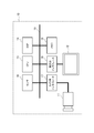
- FIG. 1 is a block diagram showing an example of the configuration of the biological information display apparatus according to the present embodiment.
- the biological information display device 10 can be configured by an information processing device such as a notebook PC (Personal Computer), a tablet terminal, or a smartphone.
- the biological information display device 10 includes an imaging unit, a processing unit, and a display unit.
- the imaging unit and the display unit may be configured integrally, or may be configured separately and attached in combination with each other.
- the biological information display device 10 includes a camera 11 as an example of an imaging unit, a monitor 12 as an example of a display unit, a CPU (Central Processing Unit) 13, a DSP (Digital Signal Processor) 14, and a memory 15 that form a processing unit. And have.
- the camera 11 and the monitor 12 are arranged on the same plane in the apparatus housing.
- the term “on the same plane” means that the camera 11 and the monitor 12 can be seen on the same plane as long as they can be seen from the user.
- the arrangement of the camera 11 and the monitor 12 may be on the same plane.
- the camera 11 is not necessarily on the same plane, for example, at a position protruding from the monitor 12.
- the biological information display device 10 includes a sensor 16 that detects a top-and-bottom direction of a display image on the monitor 12, a camera interface 17 that inputs and outputs an imaging signal and a control signal of the camera 11, and a video signal and a control signal of the monitor 12.
- the CPU 13, DSP 14, memory 15, sensor 16, camera interface 17, and display interface 18 are connected to each other via a bus 19, and various signals or data in the operation of the device are exchanged.
- the camera 11 has an imaging lens and an imaging device such as a CCD (Charge Coupled Device) type image sensor or a CMOS (Complementary Metal Oxide Semiconductor) type image sensor.
- the camera 11 captures an image of the face of the person who is the user and acquires and outputs video data of a predetermined detection area including the skin portion of the face.
- the camera 11 is connected to the CPU 13, the DSP 14, the memory 15, and the like via the camera interface 17, and outputs video data including the captured user's face area.
- the monitor 12 is configured using a display device such as an LCD (Liquid Crystal Display) or an organic EL (ElectroLuminescence) display.
- the monitor 12 is connected to the CPU 13, the DSP 14, the memory 15, and the like via the display interface 18, inputs video data to be displayed and output on the screen, and displays an information display screen, a setting screen, and the like during the operation of the biological information display device 10. Displays various information.
- the monitor 12 is a breathing pacer for instructing the pace of breathing for heartbeat fluctuation biofeedback, an indicator indicating the state of breathing and heartbeat (determination result) of the user, a measurement result of biological information, etc.
- Various information including is displayed.
- the camera 11 is disposed in the vicinity of the outer peripheral edge of the information display screen of the monitor 12. Details of the information display screen will be described later.
- the CPU 13 is an example of a processor that executes processing of each unit of the information processing apparatus, and controls each operation in obtaining biological information, displaying biological information, displaying a monitor for heartbeat fluctuation biofeedback, and the like.
- the DSP 14 is an example of a processor that executes data processing in the information processing apparatus, and executes processing such as signal processing related to biological information and image processing related to monitor display.
- the memory 15 is configured by a storage device such as SRAM (Static Random Access Memory) or flash memory, for example, and stores various data such as an operation program of the apparatus, setting information, part information on an information display screen, and acquired biological information.
- the memory 15 functions as a working memory in various processes during operation.
- the sensor 16 functions as an example of a detection unit.
- the sensor 16 includes, for example, a six-axis sensor, and detects the orientation and rotation of the device housing (terminal) including the camera 11 and the monitor 12 by detecting acceleration in three axes. To detect.
- the sensor 16 may detect the position of the camera 11.
- the sensor 16 causes the vertical direction of the information display screen, which is the display image of the monitor 12, the position of the camera 11 (the arrangement of the camera with respect to the information display screen of the monitor 12), the orientation of the monitor 12, and the information of the camera 11 and the monitor 12. It is possible to detect the positional relationship with the display screen.
- FIG. 2A is a diagram schematically illustrating an example of the relationship between the contraction of a human heart and the amount of light absorbed in a blood vessel.
- FIG. 2B is a diagram illustrating an example of a time-series change in light intensity.
- FIG. 2A shows that the volume of the blood vessel changes in synchronization with the systole of the human heart.
- the amount of absorption of light for example, light in a specific wavelength region shown in FIG. 3
- the intensity of light also decreases (see FIG. 2B).
- the pulse wave indicates a wave motion when the pressure change in the blood vessel generated when blood is pushed out to the aorta due to the contraction of the heart is transmitted in the peripheral direction.
- the horizontal axis indicates time
- the vertical axis indicates the intensity of a signal (photoelectric pulse wave) obtained by a change in the amount of absorbed light.
- the peak appears
- the amount of light absorption is small, so the volume of the blood vessel is not increased.
- the minimum value appears the amount of light absorption is large, so The volume is increasing.
- FIG. 3 is a diagram showing an example of the absorption rate for each wavelength of light in hemoglobin.
- FIG. 3 shows that, for example, hemoglobin (blood) easily absorbs a wavelength of 400 nm (that is, green).
- the green light component has a high absorptance.
- the reflectivity of the component of red light is high. You may explain using.
- FIG. 4 is a diagram illustrating an example of each signal of the biological information extracted from the video signal of the captured image.
- the pulse wave is detected from the video of the moving image of the skin part in the detection region, and the heart rate. Or the like is obtained by calculation.
- the DSP 14 of the processing unit video data of an image captured by the camera 11 is input, a known face detection process is performed from the captured image, a face area is extracted, the skin color in the face area is recognized, and the skin color of the face The skin area (skin area) is extracted.
- the processing unit detects a pulse wave in the extracted skin region.
- the DSP 14 of the processing unit constitutes a filter unit having a band pass filter having a predetermined filter coefficient, and performs filtering processing of video data having skin color variation.
- the filter unit averages a signal (pixel value) in a predetermined range of the input video data, thereby removing a noise signal included when the camera 11 captures an image, for example. By this averaging, if there is a person in the detection area of the captured image, a person's pulse wave can be extracted, but there is a high possibility that the body's motion component or noise residual component is still included.
- the unit cuts frequency components other than the fundamental frequency of the pulse wave using the set filter coefficient.
- the filter coefficient of the filter unit is set in advance so that, for example, a signal of 30 to 120 bpm passes through the filter unit.
- a signal of 30 to 120 bpm passes through the filter unit.
- the heart rate of an adult at rest is 60 to 80 bpm.
- the range to be passed through the filter unit is set to 30 to 120 bpm.
- a waveform verification unit and a heart rate estimation unit are configured to perform a waveform verification process and a heart rate estimation process on the fundamental frequency waveform of the pulse wave.
- the waveform verification unit uses a signal corresponding to at least one cycle of the output signal of the filter unit, and detects a section of the noise signal that could not be cut by the filter unit. Judge whether there is.
- the waveform verification unit excludes the interval of the output signal determined to satisfy the predetermined condition as an invalid interval. For example, the waveform verification unit excludes signals that are extremely large and signals that are extremely small compared to a predetermined value (for example, zero).
- the processing of the waveform verification unit utilizes the knowledge that the amplitude of a person's pulse wave changes slowly within a certain range, and a signal that satisfies a predetermined condition is likely to be disturbance noise.
- the heart rate estimator calculates a human heart rate (pulse rate) based on the input interval of the frame of the image data, using the signal for at least one cycle after the filter processing and the waveform verification processing.
- a human heart rate pulse rate
- the heart rate estimation section calculates a heart rate using a signal for at least one cycle excluding the corresponding signal section.
- the heart rate estimation unit estimates the heart rate using the output signal for at least one cycle as it is.
- the signal after the filter processing and waveform verification processing has a period equivalent to that of the pulse wave signal component.
- the heart rate can be calculated by performing filter processing and waveform verification processing on the skin color variation signal of the captured image, and a living body such as a heart rate interval (RRI: RR Interval). Information can be extracted.
- RRI heart rate interval
- RSA respiratory sinus arrhythmia component
- MWSA blood pressure fluctuation
- MWSA Mayer Wave : related Sinus Arrhythmia
- the information can also be used to perform heart rate variability biofeedback.
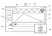
- FIG. 5A is a diagram illustrating an example (display example 1) of the information display screen of the biological information display device according to the present embodiment.
- the illustrated example shows an example of a biological information display device using a notebook PC.
- the monitor 12 displays an information display screen 30 for heartbeat variability biofeedback.
- the camera 11 is arranged at the center of the outer side of the outer peripheral edge of the display screen of the monitor 12 (the longer side of the outer peripheral edge).
- the information display screen 30 has a GUI (Graphical User Interface) related to heartbeat variability biofeedback.
- the information display screen 30 includes a breathing assistant that assists breathing as a GUI.
- the breathing assistant includes, for example, a breathing pacer 31 that indicates the pace of breathing, an indicator 32 that indicates a user's breathing and heartbeat status, and the like.
- the respiratory pacer 31 and the indicator 32 are arranged in a region near the long side closest to the camera 11 on the information display screen 30.
- the display of the breath assistant can be in various display patterns, for example, only the breath pacer, only the indicator, both the breath pacer and indicator, or neither. Note that the breathing assistant continues to operate functions such as the breathing pacer and indicator even when the display is turned off.
- the information display screen 30 may include a face image display 33 of a detection area of the user's face and a fluctuation component display 34 including a pulse wave extracted from the captured image.
- the information display screen 30 may include various detected biological information displays 35, a stop button (EXIT) 36, and display switching buttons (PAGE 1, PAGE 2) 37. The user can arbitrarily change the display mode of the information display screen 30. When the user gets used to the operation, it is possible to execute the heart rate variability biofeedback in a state where either or both of the breathing pacer and the indicator are not displayed.
- the respiratory pacer 31 is, for example, a horizontally long GUI on the information display screen 30, and a circular mark serving as a guide moves in a triangular mountain-shaped locus in the longitudinal direction, thereby inhaling (sucking) and exhaling air from the user. It is a guide display for instructing the pace and timing of (vomiting).
- the indicator 32 is an indicator display representing feedback information of a determination result indicating whether or not the heartbeat has an appropriate rhythm in accordance with the correlation between the user's breathing and the heartbeat. For example, if it is determined that the heart beats an appropriate rhythm according to the correlation between the user's breathing and the heart beat, the indicator 32 gradually increases.
- the indicator is an indicator display that represents feedback information of a determination result indicating whether or not the user is breathing along the respiratory pacer 31. For example, when the user is breathing along the breathing pacer 31, the indicator 32 gradually increases.
- the indicator 32 is, for example, a horizontally long GUI on the information display screen 30, and notifies the user whether the heart rate fluctuation is stable or not by the color of the bar display, the color ratio, and the like.
- the indicator 32 may be one that changes due to a change in state such as a change in the color of the bar, or one that moves the bar color or bar length in the longitudinal direction.
- the display color of the indicator 32 is, for example, red when the heart rate fluctuation is not stable, yellow when the heartbeat fluctuation is slightly changed from the unstable state, blue when the heartbeat fluctuation is further stable, and stable heartbeat fluctuation.
- the current state is displayed in green so that the user can intuitively recognize the state of heartbeat fluctuation at a glance.
- the indicator 32 changes to a stable state display such as red ⁇ yellow ⁇ blue ⁇ green.
- heart rate variability increases. At this time, the fluctuation of RRI becomes large, and generally the value of RRI becomes large.
- the face image display 33 shows a face detection area extracted from the captured image.
- a lattice-shaped portion in the figure indicates a skin area of the face.
- the RRI can be calculated, for example, by the interval between the peaks of the waveform of the fluctuation component display 34 in the figure.
- the camera 11 is located at the center of the information display screen 30 of the monitor 12 in the long side direction.
- the breathing pacer 31 and the indicator 32 are located in a region near the long side closest to the camera 11.
- the angle of view at the time of imaging by the camera 11 becomes an appropriate angle for imaging the user's face and acquiring biometric information. Therefore, when performing heart rate variability biofeedback, if the user turns his / her face to view the breathing pacer 31 on the information display screen 30, it is suitable for the case where the heart rate is naturally (automatically) measured by the captured image of the camera 11. The user's face is photographed at the imaged position and angle.
- the size of the user's face area in the captured image can be set to an appropriate size depending on the positional relationship and distance between the camera 11 and the respiratory pacer 31 on the information display screen 30.
- the respiratory pacer 31 and the indicator 32 are arranged in a range that can be confirmed by the user only by moving the line of sight or without moving the line of sight as much as possible.
- the arrangement of the respiratory pacer 31 and the indicator 32 on the information display screen 30 includes, for example, the position of the camera 11 detected by the sensor 16, the orientation of the monitor 12 and the information display screen 30, and the position of the relative position between the camera 11 and the information display screen 30. Set according to the relationship.
- the position of the camera 11 and the positional relationship between the camera 11 and the information display screen 30 of the monitor 12 are set as initial setting information by the user, information acquired from an OS (Operating System) that operates the apparatus, and default settings of the apparatus. Detected information, information acquired from terminal information of the apparatus, and the like.
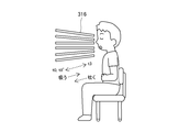
- the captured image 40 shown in the lower right in FIG. 5A when the user is looking at the breathing pacer 31 or the indicator 32, the captured image of the front of the face can always be obtained by the camera 11. .
- the user's face can be easily detected, and the skin area (skin area) of the skin color of the face can be acquired largely and stably.
- the movement of the user's face can be suppressed, and even when the face moves, the change in the angle with respect to the camera 11 is small, so the influence of the movement of the face can be reduced.
- heartbeat disturbance when acquiring a heartbeat from a captured image can be suppressed, biological information relating to heartbeat fluctuation can be stably acquired, and detection accuracy of biological information can be improved.
- usability can be improved by detecting biometric information in a non-contact manner using a captured image and performing heartbeat fluctuation biofeedback.
- the camera 11 is preferably configured to be integrally arranged near the outer peripheral edge of the monitor 12 in the apparatus housing, such as a notebook PC, a tablet terminal, or a smartphone. In this case, the camera 11 is disposed either above or below the central portion of the information display screen 30 of the monitor 12.
- the camera 11 is more preferably arranged at the upper center portion of the information display screen 30 from the viewpoint of the suitability of the angle of view when capturing a face image of the user and the stability of detection of the skin region.
- main GUIs such as the respiratory pacer 31 and the indicator 32 are arranged in a central region in the left-right direction of the screen, an upper region in the vertical direction, and an area as close to the camera 11 as possible.
- the information display screen 30 determines a landscape screen or a portrait screen according to the position of the camera 11 and the top and bottom direction of the information display screen 30.
- the user can check the respiratory pacer 31 and the indicator 32 with only a line of sight movement and as little eye movement as possible.
- the camera 11 may be configured separately from the monitor 12 and attached in combination with each other.
- the camera 11 is mounted in the vicinity of the monitor 12 by an attachment member such as a bracket.
- the positional relationship between the camera 11 and the information display screen 30 of the monitor 12 is the same as in the case where the camera 11 and the monitor 12 are integrally arranged, and the main components such as the breathing pacer 31 and the indicator 32 are located in an area close to the camera 11.
- a simple GUI is arranged.
- the main GUIs such as the respiratory pacer 31 and the indicator 32 on the information display screen 30 11 is arranged close to the region closer to 11.
- the camera 11 is displaced from the central portion of the information display screen 30 of the monitor 12 to the left or right side, and the imaging optical system of the camera 11 is provided with a lens shift function so as to capture images from an oblique direction. It is good also as a structure which obtains the picked-up image which looked at the face of from the front.
- the position information set according to the initial setting is registered by the user, the position information corresponding to the model of the device terminal is acquired, the position information of the preset default setting acquired from the setting information of the OS is used. For example, it may be obtained by various methods.
- the device terminal information model information
- the camera position database for each terminal type to acquire the camera position information for the corresponding model. It is.
- the respiratory pacer 31 and the indicator 32 are not limited to those expressed by separate GUI displays, and the respiratory pacer 31 and the indicator 32 may be expressed by an integral GUI display.
- a respiratory pacer by GUI movement or size change and to express an indicator by GUI color change or the like.
- a sound generation unit such as a speaker may be provided in the biological information display device, and the breathing pacer may be configured to instruct the user the breathing timing by using the sound uttered from the sound generation unit together with the display of the information display screen.
- only the respiratory pacer may be displayed on the information display screen, and a sound uttered from the sound generation unit may be used as an indicator to notify the user of the state of respiratory fluctuation by sound.
- FIG. 5B is a diagram illustrating an example of an information display screen according to a comparative example.
- a camera 511 is arranged at the left end outside the long side of the information display screen 530 of the monitor 512.
- the breathing pacer 531 is away from the camera 511.
- a user's face is imaged diagonally like the captured image 540 shown in the lower right in the figure, face detection is difficult to perform, and the skin area of the skin color of the face in the captured image is reduced.
- the movement of the face is increased by moving the line of sight from side to side or up and down. Further, when the face moves, the angle change with respect to the camera 511 is large, and the influence of the face movement becomes large. Therefore, in this comparative example, the biological information related to heart rate variability may be disturbed and may not be stably acquired. For this reason, the subject which cannot perform desirable heart rate variability biofeedback by a non-contact method arises.
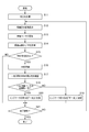
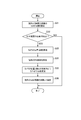
- FIG. 6 is a flowchart showing a processing procedure during the operation of the heart rate variability biofeedback in the present embodiment.
- the heart rate variability biofeedback is executed mainly by the control of the CPU 13 by executing a predetermined program in the CPU 13 of the biological information display device 10.
- the biological information display device 10 performs various initialization processes related to this operation when the operation of the heart rate variability biofeedback is started (S11).
- the biological information display device 10 initializes the parameters of the respiratory pacer 31 and the indicator 32 displayed on the information display screen 30.
- the biological information display device 10 sets the parameter of the indicator to a “mismatch” state where the heartbeat is not stable, sets the parameter of the respiratory pacer to the initial state (start position, start state), and stores it in the memory 15. Clear the stored RRI data up to the present time.
- the biological information display device 10 displays an information display screen 30 including a respiratory pacer 31 and an indicator 32 on the monitor 12 as a GUI related to heartbeat variability biofeedback (S12).
- the biological information display device 10 starts imaging the face of the user facing the information display screen 30 with the camera 11 in the vicinity of the monitor 12, and continuously captures the captured image of the moving image including the skin area of the face. get.
- the biological information display device 10 updates the respiratory pacer 31 on the information display screen 30 as needed, and moves the respiratory pacer 31 at a predetermined cycle and timing to instruct the user on the breathing timing of inspiration and expiration (S13). .
- the user breathes in accordance with an instruction from the respiratory pacer 31 while looking at the respiratory pacer 31 on the information display screen 30.
- the biological information display device 10 calculates and acquires biological information from video data of a captured image of a moving image by signal processing of the DSP 14.
- the heart rate is measured by calculating and measuring RRI as biological information (S14).
- the biological information display device 10 determines whether or not the RRI is normally measured (S15).
- the biological information display apparatus 10 proceeds to an end determination process (S21).
- the biological information display apparatus 10 records the sequentially acquired RRI data in the memory 15 (S16).
- FIG. 7 is a diagram for explaining RRI output timing. It is assumed that filter processing and waveform verification processing are performed on the skin color variation signal of the captured image, and a signal waveform equivalent to the pulse wave period of the person to be observed as shown in FIG. 7 is obtained.
- the DSP 14 outputs an RRI when the signal waveform has a maximum value, and each point of the white circle and the black circle in the drawing is a timing at which the RRI measurement determination of S15 in FIG. 6 is executed.
- the DSP 14 sequentially updates the RRI at the timing of the black circle maximum point.
- the biological information display apparatus 10 calculates the fluctuation of the RRI data recorded in the memory 15 and confirms the regularity (periodicity) of the RRI in a certain section (S17). At this time, the biological information display apparatus 10 determines whether the periodicity of the RRI and the periodicity of the respiratory pacer match as the determination result of the biological information (S18).
- the coincidence judgment of the periodicity of the RRI and the respiratory pacer is made by, for example, determining whether or not the difference between the RRI and the respiratory pacer is equal to or less than a predetermined threshold value. By such periodicity coincidence determination, it is possible to determine whether or not the user's heartbeat and respiration match, that is, whether or not the heartbeat variability is stable with little mental stress.
- the biological information display device 10 updates the state of the indicator 32 on the information display screen 30 to “mismatch” (S19). In the initial state, since the indicator 32 is in a “mismatch” state, the indicator 32 is updated for a while after the operation is started. If the biological information display device 10 determines that the RRI and the periodicity of the respiratory pacer match, the biological information display device 10 updates the state of the indicator 32 on the information display screen 30 to “match” (S20). That is, when the measured RRI of the user matches the periodicity of the respiratory pacer displayed on the screen, the state of the indicator 32 changes to “match”.
- the biological information display device 10 determines whether or not an end operation has been performed by pressing the stop button 36 (S21), and ends the operation if the end operation has been performed. If the end operation has not been performed, the biological information display device 10 returns to the information display screen display process in step S12, repeatedly executes the above-described heartbeat variability biofeedback process, and continues until the end operation is performed.
- GUIs such as the respiratory pacer 31 and the indicator 32 displayed on the information display screen 30 are appropriately arranged depending on the positional relationship between the monitor 12 and the camera 11 and the direction of the information display screen 30. Therefore, an example of GUI arrangement according to various conditions in the present embodiment will be described.
- FIG. 8A is a diagram showing a display example 2 of the information display screen according to the present embodiment.
- the camera 11 is arranged in the center portion outside the long side of the outer peripheral edge of the display screen of the monitor 12 (the upper central portion of the long side of the outer peripheral edge).
- the information display screen 302 displayed on the monitor 12 is horizontally long with the long side being horizontal.
- the horizontally long breathing pacer 31 and the indicator 32 are arranged in a region near the long side closest to the camera 11, that is, in the upper center portion of the information display screen 302.
- a face image display 33 is arranged on the left side of the breathing pacer 31, and a menu display 38 such as a stop button and a display switching button is arranged in a vertically long area at the left end of the screen below the face image display 33.
- an acquired data display 39 such as a fluctuation component display including a pulse wave and various biological information displays is arranged in a region below the respiratory pacer 31 and the indicator 32.
- various image data such as a skin color average value acquired from a captured image of the user's face area, heart rate (HR), heart rate variability (RRI) history information, various biological indices (CV-RR). SDNN, rMSSD, LF / HF, tone, entropy, etc.), Lorentz plot, etc. can be displayed.
- FIG. 8B is a diagram showing a display example 3 of the information display screen according to the present embodiment.
- the camera 11 is arranged in the central portion outside the short side of the outer peripheral edge of the display screen of the monitor 12 (the central portion on the left side of the short side of the outer peripheral edge).
- the information display screen 303 displayed on the monitor 12 is horizontally long with the long side being horizontal.
- a vertically long breathing pacer 31 and an indicator 32 are arranged in a region in the vicinity of the short side closest to the camera 11, that is, in the central portion on the left side of the information display screen 303.
- a face image display 33 is arranged on the upper side of the breathing pacer 31, and a menu display 38 is arranged in a horizontally long area at the top of the screen on the right side of the face image display 33.
- an acquired data display 39 is arranged in a region below the menu display 38 on the right side of the respiratory pacer 31 and the indicator 32.
- FIG. 9 is a diagram showing a display example 4 of the information display screen according to the present embodiment.
- Display example 4 shows a display example when the biological information display device is configured by a smartphone which is a communication terminal.
- the biological information display device 104 has a vertically long rectangular monitor 12 in a vertically rounded casing, and is slightly on the right side from the center in the horizontal direction outside the short side of the outer periphery of the monitor 12 (above the short side of the outer periphery).
- a camera 11 that captures an image of the user's own face is disposed at a position shifted to the position.
- the information display screen 304 displayed on the monitor 12 is vertically long with the long side being vertical.
- the horizontally long breathing pacer 31 and the indicator 32 are arranged in a region near the short side closest to the camera 11, that is, in an upper portion of the information display screen 304. Further, on the upper part of the respiratory pacer 31, a face image display 33 and a fluctuation component display 34 including a pulse wave are arranged. In this case, even if the user holds firmly with both hands so as not to move the apparatus housing as much as possible in order to stably measure the heartbeat, the breather pacer 31 and the indicator 32 are located on the upper part of the monitor 12 and are hidden. It is displayed without.
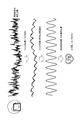
- FIG. 10A is a diagram showing a display example 1 of the respiratory pacer on the information display screen according to the present embodiment.
- the breathing pacer 311 of the display example 1 instructs the user on the breathing pace and timing by moving a circular mark 311a serving as a guide along a triangular mountain-shaped locus 311b.
- the breathing pacer 311 represents each time t1 to t8 in one breathing cycle as an index.
- the times t1 to t8 are not displayed.
- the intervals t0-t1, t1-t2,..., t7-t8 are the same time interval.
- t0-t3 which is the top of the mountain of the locus 311b of the breathing pacer 311, sucks.
- the mark 311a of the respiratory pacer 311 stops at t0, accelerates at t0-t1, accelerates at a constant speed after t1-t2, decelerates at t2-t3, gradually increases from the stop, moves at a constant speed, and then decelerates. Then, the intake period (suction section) ends. For example, at t0-t1, the mark 311a accelerates until reaching the speed of t1-t2, and at t2-t3, the mark 311a decelerates from the speed of t1-t2. The mark may be stopped at t3 when the inspiration and expiration are switched.
- t3-t8 which is a descending mountain of the trajectory 311b of the breathing pacer 311, is a section that exhales.
- the mark 311a of the breathing pacer 311 indicates that t3-t4 is accelerated, t4-t5, t5-t6, t6-t7 are constant speed, t7-t8 is decelerated, and stopped at t8. It moves at a speed, then decelerates and stops, and the expiration period (exhalation period) ends.
- the mark 311a accelerates until reaching a speed of t4-t5, and at t7-t8, the mark 311a decelerates from the speed of t6-t7.
- the moving speed of the mark 311 a serving as a guide changes in each section according to the timing of breathing.
- FIG. 10B is a diagram showing a display example 2 of the respiratory pacer on the information display screen according to the present embodiment.
- the breath pacer 312 of display example 2 instructs the user on the pace and timing of breathing by changing the size of the circular mark.
- t0 start inspiration start
- t3 switch from inspiration to expiration
- t8 end expiration timing marks are shown side by side.
- one circular mark changes from small to large to small, and is enlarged in a sucking section and reduced in a breathing section.
- the size of the mark may be changed from large to small to large.
- an indicator function may be provided by changing the color of the breath pacer mark, and the breath pacer may also serve as the indicator. In this way, by displaying the respiratory pacer whose mark size changes at a predetermined speed, the user can appropriately adjust the pace and timing of the breath according to the movement of the respiratory pacer.
- FIG. 10C is a diagram showing a display example 3 of the respiratory pacer on the information display screen according to the present embodiment.
- the breath pacer 313 of the display example 3 instructs the user on the pace and timing of breathing by changing the length of the bar-shaped bar.
- the breathing pacer 313 shows a horizontally long bar display, and in the section from t0 to t3, the bar length gradually increases from the zero or short state toward the right end from the left end to the t8 from t3 to t8. In the section where the water is discharged, the bar length gradually decreases from the right end toward the left end.
- the bar of the respiratory pacer 313 may be rotated to display a vertically long bar.
- an indicator function may be provided by changing the color of the breath pacer mark, and the breath pacer may also serve as the indicator. In this way, by displaying the respiratory pacer whose bar length changes at a predetermined speed, the user can appropriately adjust the pace and timing of the breath according to the movement of the respiratory pacer.
- FIG. 10D is a diagram showing a display example 4 of the respiratory pacer on the information display screen according to the present embodiment.
- the respiratory pacer 314 of the display example 4 is a modification of the display example 3, and in the horizontal or vertical bar display, the length of the bar-shaped bar is changed so that the length expands and contracts from the center to both ends. Instructs the user the pace and timing of breathing.
- the breathing pacer 314 shows a horizontally-long horizontal bar display.
- the breathing pacer 314 gradually extends from the center to the left and right ends from a state where the length of the bar is zero or short, and t3 In the section from t8 to t8, the bar is gradually shortened from both ends toward the center from the long state.
- the bar of the respiratory pacer 314 may be rotated to display a vertically long bar.
- an indicator function may be provided by changing the color of the breath pacer mark, and the breath pacer may also serve as the indicator. In this way, by displaying the respiratory pacer whose bar length changes at a predetermined speed, the user can appropriately adjust the pace and timing of the breath according to the movement of the respiratory pacer.
- FIG. 10E is a diagram showing a display example 5 of the respiratory pacer on the information display screen according to the present embodiment.
- the breath pacer 315 of the display example 5 instructs the user on the pace and timing of breathing by moving an indicator such as a colored band or mark on the circumference of the ring-shaped display area like a clock.
- the breathing pacer 315 indicates one period of breathing every half-lap, and shows a section for inhaling and exhaling twice in one period. In addition, it is good also as a pace display for one breath in 1 round.
- Respiratory pacer 315 indicates the interval of sucking by the ring indicator moving clockwise around t0-t3 and t0'-t3 ', followed by the ring at t3-t8 and t3'-t8'. Indicates the section to be sucked by moving the indicator clockwise around the circumference.
- the user can appropriately adjust the pace and timing of the breath by the movement of the respiratory pacer.
- FIG. 10F is a diagram showing a display example 6 of the respiratory pacer on the information display screen according to the present embodiment.
- the breath pacer 316 of the display example 6 instructs the user on the pace and timing of breathing by an animation display schematically showing the breathing state of a person.
- the breathing pacer 316 indicates a section for sucking and a section for breathing out by a change in a picture of a person and a plurality of radial lines. For example, in the section from t0 to t3, the line color changes from the outside toward the person or the length of the line decreases, and in the section from t3 to t8, the line color changes from the person to the outside. Or the length of the line becomes longer.
- the user can appropriately adjust the pace and timing of the breath according to the movement of the respiratory pacer.
- FIG. 11 is a flowchart showing a processing procedure when the direction of the information display screen of the heart rate variability biofeedback in this embodiment is changed.
- FIG. 11 an example of processing when the camera 11 and the monitor 12 of the biological information display apparatus 10 are rotated and the direction of the information display screen 30 is changed by moving the apparatus housing or the like is shown.
- the display control accompanying the change in the orientation of the information display screen 30 is executed mainly by the control of the CPU 13 by executing a predetermined program in the CPU 13 of the biological information display device 10.
- the display control process shown in FIG. 11 is started by detecting the change in the direction of the information display screen 30, such as being called as an interrupt process in the CPU 13 when the rotation of the monitor 12 is detected by the sensor 16, for example, and the execution of the process is started. .
- the biological information display device 10 reads information on each GUI currently displayed on the information display screen 30 from the memory 15 (S31).
- the biometric information display device 10 acquires at least one of parameters indicating the type, arrangement, orientation, size, and state of each GUI as GUI information.
- the biological information display device 10 determines whether or not the GUI needs to be changed on the current information display screen 30 (S32).
- the biological information display device 10 detects the top-to-bottom direction of the monitor 12 by the sensor 16, the orientation of the information display screen 30 displayed on the monitor 12 with respect to the user, and the positions of the information display screen 30 of the camera 11 and the monitor 12. Whether or not to change the GUI is determined based on the relationship.
- the direction of the information display screen can be detected by other methods such as detecting the direction of the user's face from the captured image of the camera 11 and detecting the direction of the information display screen 30.
- the positional relationship between the camera 11 and the information display screen 30 of the monitor 12 is determined from the initial setting information by the user, the information acquired from the OS that operates the apparatus, the information set as the default setting of the apparatus, and the terminal information of the apparatus. Detection is possible based on any information such as information to be acquired.
- the biometric information display device 10 first acquires the position information of the camera 11 with respect to the monitor 12 when the GUI needs to be changed on the current information display screen 30 (S33). As the position information of the camera 11, physical positions such as up, down, left, and right are acquired with respect to the monitor 12 in the apparatus housing (terminal). Further, the biological information display device 10 acquires the top and bottom information of the device housing (terminal) (S34). Then, the biological information display device 10 changes the GUI according to the camera position and the top / bottom direction of the terminal (that is, the direction of the information display screen 30) based on the position information of the camera 11 and the top / bottom information of the terminal (S35).
- the biological information display device 10 updates the information on each GUI on the current information display screen 30, and stores the information on each GUI such as the direction of the information display screen 30 and the direction of the GUI. 15 (S36). Then, the biological information display device 10 ends this process. In addition, when there is no need to change the GUI on the current information display screen 30, the biological information display device 10 ends this process as it is.
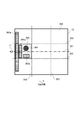
- FIG. 12A is a diagram illustrating an example (display example 5) of the information display screen of the biological information display device according to the present embodiment.
- a state in which the camera 11 and the monitor 12 are rotated clockwise by 90 degrees is illustrated, and a first state ⁇ second state ⁇ third state ⁇ fourth state is illustrated in order from left to right in the drawing. .
- the camera 11 in the first state shown at the left end in the figure, the camera 11 is arranged at the center portion outside the short side of the outer peripheral edge of the display screen of the monitor 12 (upper central portion of the short side of the outer peripheral edge). .
- the information display screen 305 displayed on the monitor 12 is vertically long with the long side being vertical.
- the horizontally long breathing pacer 31 is arranged in a region near the long side closest to the camera 11, that is, in the center of the upper end of the information display screen 305.
- the camera 11 In the second state in which the apparatus housing is rotated 90 degrees clockwise from the first state, the camera 11 is arranged at the right center portion of the information display screen 305 as shown second from the left in the figure. .
- the vertically long breathing pacer 31 is arranged at the center of the right end of the information display screen 305 according to the position of the camera 11.
- the camera 11 is arranged at the lower center portion of the information display screen 305 as shown in the third position from the left in the figure. It will be. At this time, with the rotation of the camera 11 and the monitor 12, the horizontally long breathing pacer 31 is arranged at the center of the lower end of the information display screen 305 in accordance with the position of the camera 11. Further, in the fourth state in which the device casing is rotated 90 degrees clockwise from the third state, the camera 11 is arranged at the left center of the information display screen 305 as shown in the fourth (right end) from the left in the figure. Will be. At this time, along with the rotation of the camera 11 and the monitor 12, the vertically long breathing pacer 31 is arranged at the center of the left end on the information display screen 305 according to the position of the camera 11.
- FIG. 12B is a diagram illustrating an example of an information display screen according to a comparative example.
- the position of the respiratory pacer 531 on the information display screen 530 does not change with the rotation of the camera 511 and the monitor 512. ing.
- the position of the respiratory pacer 531 is fixed in the information display screen 530.
- the breathing pacer 531 is at a position away from the camera 511 as in the third state from the third to the fourth state at the right end in FIG. For this reason, it may be a captured image obtained by imaging the user's face obliquely, or the user's face may move when the heart rate variability biofeedback is executed, which may cause a problem that biometric information cannot be acquired stably.
- GUI layout example on information display screen Below, some examples of GUI arrangement taking into account the change of the orientation of the information display screen will be described.
- GUIs such as respiratory pacers 31 and indicators 32 having various shapes are arranged
- the arrangement conditions of GUIs according to various conditions will be described.
- FIGS. 13A and 13B are diagrams showing a GUI arrangement example 1 of the information display screen according to the present embodiment.
- the camera 11 is arranged at the central portion outside the long side of the outer peripheral edge of the display screen of the monitor 12 (the upper central portion of the long side of the outer peripheral edge).
- the information display screen 306 displayed on the monitor 12 is horizontally long with the long side being horizontal.
- the alternate long and two short dashes line is perpendicular to the long side closest to the camera 11 on the information display screen 306 and passes through the camera 11, and the alternate long and short dash line bisects the short side of the information display screen 306 in two.
- the broken lines indicate three-divided straight lines 353 that divide the long side of the information display screen 306 into three equal parts.
- a central area of the dividing line is a pacer arrangement area 365.
- a horizontally moving horizontal breathing pacer or indicator 361, 362, a vertically moving vertically long breathing pacer or indicator 363, a concentrically moving circular breathing pacer or indicator 364, is provided in the pacer placement region 365.
- a horizontally moving horizontal breathing pacer or indicator 361, 362, a vertically moving vertically long breathing pacer or indicator 363, a concentrically moving circular breathing pacer or indicator 364, is provided in the pacer placement region 365.
- the horizontally long breathing pacers or indicators 361 and 362 are in a state where the moving direction intersects the camera passing straight line 351 perpendicularly.
- the breathing pacer only needs to be located within the pacer placement region 365, but is preferably located on the camera passing straight line 351.
- FIG. 13B shows a state where the monitor 12 and the camera 11 of the apparatus of FIG. 13A are rotated 90 degrees counterclockwise.
- the information display screen 306 displayed on the monitor 12 is vertically long with the long side being vertical, and is on the camera passing straight line 351 in the information display screen 306 and in the vicinity of the camera 11, that is, the information display screen.
- a region on the left side of the bisector of the short side and the center of the bisector of the long side at the center of the left side of 306 is a pacer arrangement region 365.
- a vertically moving vertical breathing pacer or indicator 361a, 362a that moves vertically, a horizontally long horizontal breathing pacer or indicator 363a that moves horizontally, a circular breathing pacer or indicator 364 that moves concentrically, One is arranged.
- the vertically long breathing pacers or indicators 361 a and 362 a are in a state where the moving direction intersects the camera passing straight line 351 perpendicularly.
- a part of the breathing pacer or indicator 362, 362a may protrude from the pacer placement region 365.
- the breathing pacer only needs to be located within the pacer placement region 365, but is preferably located on the camera passing straight line 351.
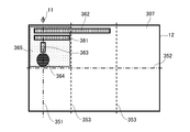
- FIGS. 14A and 14B are diagrams showing a GUI arrangement example 2 of the information display screen according to the present embodiment.
- the camera 11 is arranged at one end outside the long side of the outer peripheral edge of the display screen of the monitor 12 (upper left end of the long side of the outer peripheral edge).
- the information display screen 307 displayed on the monitor 12 is horizontally long with its long side being horizontal.
- the alternate long and two short dashes line is perpendicular to the long side closest to the camera 11 on the information display screen 307 and passes through the camera 11, and the alternate long and short dash line bisects the short side of the information display screen 307 in two.
- the broken lines indicate three-divided straight lines 353 that divide the long side of the information display screen 307 into three equal parts.
- On the information display screen 307 it is on the camera passing straight line 351 and in the vicinity of the camera 11, that is, the upper left end of the information display screen 307, above the bisector of the short side and 3 etc. of the long side
- a region at the left end of the dividing line is a pacer arrangement region 365.
- a horizontally moving horizontal breathing pacer or indicator 361, 362, a vertically moving vertically long breathing pacer or indicator 363, a concentrically moving circular breathing pacer or indicator 364, is provided.
- the breathing pacer only needs to be located within the pacer placement region 365, but is preferably located on the camera passing straight line 351.
- FIG. 14B shows a state in which the monitor 12 and the camera 11 of the apparatus of FIG. 14A are rotated 90 degrees clockwise.
- the information display screen 307 displayed on the monitor 12 is vertically long with the long side being vertical.
- the information display screen 307 is on the camera passing straight line 351 and in the vicinity of the camera 11, that is, the information display screen.
- a region on the right side of the short side bisector and the upper end of the long side bisector, which is the upper right end portion of 307, is a pacer placement region 365.
- the pacer placement region 365 at least one of a vertically moving vertical breathing pacer or indicator 361a, 362a that moves vertically, a horizontally long horizontal breathing pacer or indicator 363a that moves horizontally, a circular breathing pacer or indicator 364 that moves concentrically, One is arranged.
- a part of the breathing pacer or indicator 362, 362a may protrude from the pacer placement region 365.
- the breathing pacer only needs to be located within the pacer placement region 365, but is preferably located on the camera passing straight line 351.
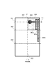
- FIG. 15A and 15B are diagrams showing a GUI arrangement example 3 of the information display screen according to the present embodiment.
- the camera 11 is arranged at the central portion outside the short side of the outer peripheral edge of the display screen of the monitor 12 (upper central portion of the short side of the outer peripheral edge).
- the information display screen 308 displayed on the monitor 12 is vertically long with the long side being vertical.
- a two-dot chain line is a camera passing straight line 351 that passes through the camera 11 perpendicular to the short side closest to the camera 11 on the information display screen 308, and a broken line is divided into three parts that divide the long side or short side of the information display screen 308 into three equal parts Each straight line 353 is shown.
- a central area of the equipartition line is a pacer arrangement area 365.
- a horizontally moving horizontal breathing pacer or indicator 361, 362, a vertically moving vertically long breathing pacer or indicator 363, a concentrically moving circular breathing pacer or indicator 364, is provided in the pacer placement region 365.
- the horizontally long breathing pacers or indicators 361 and 362 are in a state where the moving direction intersects the camera passing straight line 351 perpendicularly.
- the breathing pacer only needs to be located within the pacer placement region 365, but is preferably located on the camera passing straight line 351.
- FIG. 15B shows a state in which the monitor 12 and the camera 11 of the apparatus of FIG. 15A are rotated 90 degrees counterclockwise.
- the information display screen 308 displayed on the monitor 12 is horizontally long with the long side being horizontal, and is on the camera passing straight line 351 in the information display screen 308 and in the vicinity of the camera 11, that is, the information display screen.
- a region at the left end of the long side bisector and the center of the short side bisector, which is the left central portion of 308, is defined as a pacer placement region 365.
- a vertically moving vertical breathing pacer or indicator 361a, 362a that moves vertically, a horizontally long horizontal breathing pacer or indicator 363a that moves horizontally, a circular breathing pacer or indicator 364 that moves concentrically, One is arranged.
- the vertically long breathing pacers or indicators 361 a and 362 a are in a state where the moving direction intersects the camera passing straight line 351 perpendicularly.
- a part of the breathing pacer or indicator 362, 362a may protrude from the pacer placement region 365.
- the breathing pacer only needs to be located within the pacer placement region 365, but is preferably located on the camera passing straight line 351.
- FIGS. 16A and 16B are diagrams showing a GUI arrangement example 4 of the information display screen according to the present embodiment.
- the camera 11 is arranged at one end outside the short side of the outer peripheral end of the display screen of the monitor 12 (upper left end of the short side of the outer peripheral end).
- the information display screen 309 displayed on the monitor 12 is vertically long with the long side being vertical.
- a two-dot chain line is a camera passing straight line 351 passing through the camera 11 perpendicular to the short side closest to the camera 11 on the information display screen 309, and a broken line is divided into three parts dividing the long side or short side of the information display screen 309 into three equal parts.
- Each straight line 353 is shown.
- a pacer arrangement region 365 On the information display screen 309, it is on the camera passing straight line 351 and in the vicinity of the camera 11, that is, the upper left end of the information display screen 309, the upper end of the long side bisector, and the short side 3 A region at the left end portion of the bisector is a pacer arrangement region 365.
- One is arranged.
- the breathing pacer only needs to be located within the pacer placement region 365, but is preferably located on the camera passing straight line 351.
- FIG. 16B shows a state in which the monitor 12 and the camera 11 of the apparatus of FIG. 16A are rotated 90 degrees clockwise.
- the information display screen 309 displayed on the monitor 12 is horizontally long with the long side being horizontal, and is on the camera passing straight line 351 in the information display screen 309 and in the vicinity of the camera 11, that is, the information display screen.
- the area at the right end of the long side bisector and the upper end of the short side bisector, which is the upper right end of 309, is referred to as a pacer placement area 365.
- the pacer placement region 365 at least one of a vertically moving vertical breathing pacer or indicator 361a, 362a that moves vertically, a horizontally long horizontal breathing pacer or indicator 363a that moves horizontally, a circular breathing pacer or indicator 364 that moves concentrically, One is arranged.
- a part of the breathing pacer or indicator 362, 362a may protrude from the pacer placement region 365.
- the breathing pacer only needs to be located within the pacer placement region 365, but is preferably located on the camera passing straight line 351.
- the biological information display device 10 images the face of the user who is the user and acquires video data of the detection area including the skin portion of the face of the user from the captured image.
- a camera 11 serving as an imaging unit, and a processing unit that acquires biological information including information on a person's pulse wave from video data in a detection region, and generates an information display screen for performing heartbeat fluctuation biofeedback using the biological information CPU 13 and DSP 14, and a monitor 12 as a display unit for displaying an information display screen.
- the camera 11 and the monitor 12 are disposed on the same plane in the apparatus housing.
- the processing unit generates an information display screen 30 including a breathing assistant for assisting breathing of the subject for heart rate variability biofeedback, and at least a part of the breathing assistant passes through the camera 11 on the information display screen 30.
- the straight line passing through the camera 11 intersects the outer peripheral edge of the monitor 12 closest to the camera 11 perpendicularly.
- the breathing assistant includes a breathing pacer 31 that indicates the breathing pace of the subject. At least a part of the breathing pacer 31 is arranged on a straight line passing through the camera 11 on the information display screen 30.
- the person to be observed is looking at the heartbeat using the captured image captured by the camera 11 while viewing the respiratory pacer 31 as an example of the respiratory assistant on the information display screen 30.
- the face of the person to be observed is photographed at an imaging position and an angle of view suitable for measuring.
- the breathing pacer 31 is arranged in a range that can be confirmed by the user only by moving the line of sight or without moving the line of sight as much as possible. For this reason, when the user is looking at the breathing pacer 31, the camera 11 can always obtain a captured image of the front of the face.
- the skin area (skin area) of the skin color of the face can be acquired largely and stably.
- the movement of the user's face can be suppressed, and even when the face moves, the change in the angle with respect to the camera 11 is small, so the influence of the movement of the face can be reduced. Therefore, heartbeat disturbance when acquiring a heartbeat from a captured image can be suppressed, biological information relating to heartbeat fluctuation can be stably acquired, and detection accuracy of biological information can be improved.
- usability can be improved by detecting biometric information in a non-contact manner using a captured image and performing heartbeat fluctuation biofeedback.
- the biological information display device 10 includes an indicator 32 that indicates the state of breathing and heartbeat of the person to be observed as a breathing assistant, and at least a part of the indicator 32 is arranged on a straight line passing through the camera 11 on the information display screen 30. Is done.
- the breathing pacer 31 and the indicator 32 are arranged in a range that can be confirmed by the user only by moving the line of sight or without moving the line of sight as much as possible.
- the camera 11 can always obtain a captured image almost in front of the face, the user's face can be easily detected, and the facial skin area is enlarged. It can be acquired stably. Therefore, heartbeat disturbance when acquiring a heartbeat from a captured image can be suppressed, biological information relating to heartbeat fluctuation can be stably acquired, and detection accuracy of biological information can be improved.
- the breathing assistant includes an indicator 32 indicating the state of breathing and heartbeat of the subject, and the breathing pacer 31 is moved at least partially on the information display screen 30 to breathe the subject.
- the indicator 32 indicates the state of the person to be observed because at least a part of the indicator 32 moves on the information display screen 30, and the movement direction of the breathing pacer 31 and the indicator 32 is the same. is there.
- various modes are possible, such as the respiratory pacer 31 and the indicator 32 moving in the same direction on a linear trajectory.
- the breathing assistant includes an indicator 32 indicating the state of breathing and heartbeat of the subject, and the breathing pacer 31 is moved at least partially on the information display screen 30 to breathe the subject.
- the indicator 32 indicates the state of the person to be observed as at least a part of the indicator 32 moves on the information display screen 30, and the movement directions of the breathing pacer 31 and the indicator 32 are different.
- the breathing pacer 31 moves along a mountain-shaped linear, straight, or circumferential locus
- the indicator 32 changes in size
- the moving direction of the breathing pacer 31 and the indicator 32 is orthogonal.
- the user can appropriately adjust the pace and timing of breathing by the movement of the breathing pacer, the indicator can be easily checked, and the heart rate variability biofeedback can be appropriately executed.
- the breathing assistant includes an indicator 32 indicating the state of breathing and heartbeat of the subject, and the breathing pacer 31 is moved at least partially on the information display screen 30 to breathe the subject.
- the indicator indicates the state of the person to be observed by a change in state.
- the breathing pacer 31 moves in a mountain-shaped linear, linear, or circumferential locus, and the indicator 32 can take various forms such as a state in which the state such as color and size changes. Accordingly, the user can appropriately adjust the pace and timing of breathing by the movement of the breathing pacer, the indicator can be easily checked, and the heart rate variability biofeedback can be appropriately executed.
- the moving direction of the respiratory pacer 31 intersects with a straight line passing through the camera 11. Thereby, the movement of the user's face when looking at the breathing pacer can be suppressed, and biometric information related to heartbeat fluctuation can be stably acquired.
- the respiratory pacer 31 is arranged in a pacer arrangement area 365 positioned on a straight line passing through the camera 11 on the information display screen 30, and the pacer arrangement area 365 is parallel to the straight line passing through the camera 11.
- the information display screen 30 is divided into three central areas divided by two lines.
- the respiratory pacer 31 is arranged in a pacer arrangement area 365 positioned on a straight line passing through the camera 11 on the information display screen 30, and the pacer arrangement area 365 is parallel to the straight line passing through the camera 11.
- the information display screen 30 is divided into three regions divided by two straight lines and is located in an end region.
- the pacer arrangement region 365 is located in a two-region region on the camera 11 side that is divided into two by a straight line parallel to a straight line passing through the camera 11.
- the camera 11 and the breathing pacer 31 are arranged close to each other, so that when the user looks at the breathing pacer 31, the camera 11 can always obtain a captured image almost in front of the face.
- Biological information can be acquired stably.
- the moving speed of the breathing pacer 31 changes according to the timing of breathing. For example, in each section where the respiratory cycle is divided into a plurality of sections, the beginning of sucking, the end of sucking, the beginning of vomiting, the section of the end of exhalation are delayed, and the other sections are made faster than this, or stopped in the sections inhaling and exhaling, respectively ⁇ Various modes such as acceleration ⁇ constant speed ⁇ deceleration ⁇ stop are possible. As a result, by displaying a breath pacer whose movement speed changes according to the breathing timing, the user can easily follow the breath pacer with the eyes, and the user can easily adjust the breathing pace and timing to the movement of the breathing pacer. Fluctuating biofeedback can be performed appropriately.
- the respiratory pacer 31 has a slow movement speed at the beginning and end of the breathing interval and at least one of the beginning and end of the exhalation interval. Further, the breathing pacer 31 moves at a constant speed in other sections except for the beginning and end of the breathing section and the beginning and end of the breathing section. As a result, by displaying a breath pacer whose movement speed changes according to the breathing timing, the user can easily follow the breath pacer with the eyes, and the user can easily adjust the breathing pace and timing to the movement of the breathing pacer. Fluctuating biofeedback can be performed appropriately.
- the biological information display device 10 includes a sensor 16 as a detection unit that detects the position of the camera 11, and the processing unit arranges the GUI of the information display screen 30 including the breathing assistant according to the position of the camera 11. To do.
- the respiratory pacer 31 which is an example of the respiratory assistant on the information display screen 30
- the user's face can be imaged at an imaging position and an angle of view suitable for measuring the heartbeat. Therefore, the skin area of the face can be acquired largely and stably, and the movement of the user's face can be suppressed, so that biometric information related to heartbeat fluctuation can be acquired stably.
- the biological information display device 10 includes a sensor 16 as a detection unit that detects the orientation of the monitor 12, and the processing unit corresponds to the orientation of the monitor 12 and the positional relationship between the camera 11 and the information display screen 30.
- the GUI of the information display screen 30 including the breathing assistant is arranged.
- the orientation of the information display screen 30 and the position of the camera 11 such as the orientation when the information display screen 30 of the biological information display device 10 is rotated corresponding to the portrait or landscape orientation of the landscape or portrait information display screen 30.
- the user's face can be appropriately captured according to the relationship. Therefore, the skin area of the face can be acquired largely and stably, and the movement of the user's face can be suppressed, so that biometric information related to heartbeat fluctuation can be acquired stably.
- the processing unit detects the rotation of the information display screen according to the orientation of the monitor 12 and changes the GUI according to the orientation of the information display screen 30.
- the user's face can be appropriately imaged according to the positional relationship between the orientation of the information display screen 30 and the camera 11. Therefore, the skin area of the face can be acquired largely and stably, and the movement of the user's face can be suppressed, so that biometric information related to heartbeat fluctuation can be acquired stably.
- the biological information display method includes a camera 11 serving as an imaging unit that captures the face of a user who is a user, and a monitor 12 serving as a display unit that displays biological information acquired from the captured image.
- This is a biological information display method in the biological information display device 10 in which the monitor 12 is arranged on the same plane as the camera 11 in the housing.
- the face of the person to be observed is imaged by the camera 11, video data of a detection area including the skin portion of the face of the person to be observed is acquired from the captured image, and a human pulse is obtained from the video data of the detection area.
- the biological information including the wave information is acquired, and the information display screen 30 for performing the heart rate variability biofeedback using the biological information is generated.
- an information display screen 30 including a breathing assistant for assisting the user's breathing for heartbeat fluctuation biofeedback is generated, and the information display screen 30 is displayed on the monitor 12.
- the breathing assistant is arranged on a straight line passing through the camera 11, and the straight line passing through the camera 11 intersects the outer peripheral edge of the monitor 12 closest to the camera 11 perpendicularly.
- the program of this Embodiment has the camera 11 as an imaging part which images the face of the observer who is a user, and the monitor 12 as a display part which displays the biometric information acquired from the captured image,
- the program executes each process of the biological information display method by the computer.
- the camera 11 captures the face of the person to be observed, obtains video data of a detection area including the skin portion of the face of the observer from the captured image, and a human pulse wave from the video data of the detection area.
- the method includes a step of generating an information display screen 30 including a breathing assistant for assisting a user's breathing for heartbeat variability biofeedback, and a step of displaying the information display screen 30 on the monitor 12.
- a breathing assistant for assisting a user's breathing for heartbeat variability biofeedback
- On the information display screen 30, at least a part of the assistant is arranged on a straight line passing through the camera 11, and the straight line passing through the camera 11 intersects the outer peripheral edge of the monitor 12 closest to the camera 11 perpendicularly.
- the present disclosure is useful as a biological information display device, a biological information display method, and a program capable of improving usability when performing heart rate variability biofeedback.
Landscapes
- Health & Medical Sciences (AREA)
- Life Sciences & Earth Sciences (AREA)
- Molecular Biology (AREA)
- General Health & Medical Sciences (AREA)
- Biophysics (AREA)
- Pathology (AREA)
- Engineering & Computer Science (AREA)
- Biomedical Technology (AREA)
- Heart & Thoracic Surgery (AREA)
- Medical Informatics (AREA)
- Veterinary Medicine (AREA)
- Surgery (AREA)
- Animal Behavior & Ethology (AREA)
- Physics & Mathematics (AREA)
- Public Health (AREA)
- Cardiology (AREA)
- Physiology (AREA)
- Pulmonology (AREA)
- Biodiversity & Conservation Biology (AREA)
- Dermatology (AREA)
- Measurement Of The Respiration, Hearing Ability, Form, And Blood Characteristics Of Living Organisms (AREA)
- Measuring Pulse, Heart Rate, Blood Pressure Or Blood Flow (AREA)
- Measuring And Recording Apparatus For Diagnosis (AREA)
Priority Applications (2)
| Application Number | Priority Date | Filing Date | Title |
|---|---|---|---|
| US16/968,489 US20200405245A1 (en) | 2018-02-13 | 2019-02-08 | Biological information display device, biological information display method and program |
| CN201980012970.4A CN111712187A (zh) | 2018-02-13 | 2019-02-08 | 生命信息显示设备、生命信息显示方法和程序 |
Applications Claiming Priority (2)
| Application Number | Priority Date | Filing Date | Title |
|---|---|---|---|
| JP2018-023436 | 2018-02-13 | ||
| JP2018023436A JP7133771B2 (ja) | 2018-02-13 | 2018-02-13 | 生体情報表示装置、生体情報表示方法及び生体情報表示プログラム |
Publications (1)
| Publication Number | Publication Date |
|---|---|
| WO2019159849A1 true WO2019159849A1 (ja) | 2019-08-22 |
Family
ID=67620992
Family Applications (1)
| Application Number | Title | Priority Date | Filing Date |
|---|---|---|---|
| PCT/JP2019/004685 Ceased WO2019159849A1 (ja) | 2018-02-13 | 2019-02-08 | 生体情報表示装置、生体情報表示方法及びプログラム |
Country Status (4)
| Country | Link |
|---|---|
| US (1) | US20200405245A1 (https=) |
| JP (2) | JP7133771B2 (https=) |
| CN (1) | CN111712187A (https=) |
| WO (1) | WO2019159849A1 (https=) |
Families Citing this family (7)
| Publication number | Priority date | Publication date | Assignee | Title |
|---|---|---|---|---|
| JP2020086004A (ja) * | 2018-11-19 | 2020-06-04 | 株式会社日立製作所 | 生体情報検出装置及び生体情報検出方法 |
| KR102147295B1 (ko) * | 2018-12-05 | 2020-08-24 | (주)모어씽즈 | 사용자의 자세를 모사하는 로봇 및 이를 포함하는 실시간 자세 모니터링 시스템 |
| CN116685271A (zh) | 2020-12-25 | 2023-09-01 | 安斯泰来制药株式会社 | 心律失常状态检测支援装置及程序 |
| JP7707630B2 (ja) * | 2021-04-27 | 2025-07-15 | オムロン株式会社 | 脈波検出装置および脈波検出方法、脈波検出プログラム |
| JP2022179438A (ja) * | 2021-05-19 | 2022-12-02 | カミエンス・テクノロジー株式会社 | 非接触型状態検出装置及び非接触型状態検出プログラム |
| JP7381139B1 (ja) | 2022-12-15 | 2023-11-15 | 株式会社オクチィ | プログラム、コンピュータ装置及び方法 |
| JP7732141B2 (ja) * | 2023-10-30 | 2025-09-02 | カーンズ マイケル | 呼吸同期点灯デバイス |
Citations (12)
| Publication number | Priority date | Publication date | Assignee | Title |
|---|---|---|---|---|
| US20050209503A1 (en) * | 2004-03-18 | 2005-09-22 | Elliott Stephen B | Method of presenting audible and visual cues for synchronizing the breathing cycle with an external timing reference for purposes of synchronizing the heart rate variability cycle with the breathing cycle |
| JP2008136668A (ja) * | 2006-12-01 | 2008-06-19 | Toshiba Corp | X線コンピュータ断層撮影装置及び画像処理装置 |
| JP2011255046A (ja) * | 2010-06-10 | 2011-12-22 | Nintendo Co Ltd | 呼吸指示プログラム、呼吸指示装置、呼吸指示システム、および呼吸指示処理方法 |
| JP2012205673A (ja) * | 2011-03-29 | 2012-10-25 | Citizen Holdings Co Ltd | 血圧計 |
| JP2012228540A (ja) * | 2012-07-19 | 2012-11-22 | Panasonic Corp | 呼吸確認システム、呼吸確認方法、プログラム |
| JP2015008953A (ja) * | 2013-06-28 | 2015-01-19 | フクダ電子株式会社 | 心電計 |
| WO2016006027A1 (ja) * | 2014-07-07 | 2016-01-14 | 富士通株式会社 | 脈波検出方法、脈波検出プログラム及び脈波検出装置 |
| JP2016101352A (ja) * | 2014-11-28 | 2016-06-02 | ダイキン工業株式会社 | 表示制御装置およびリラックス支援システム |
| US20160166197A1 (en) * | 2016-02-12 | 2016-06-16 | Fitbit, Inc. | Method and apparatus for providing biofeedback during meditation exercise |
| JP2017018570A (ja) * | 2015-07-10 | 2017-01-26 | 安西メディカル株式会社 | 呼吸安定化装置及びプログラム |
| WO2017187671A1 (ja) * | 2016-04-27 | 2017-11-02 | ユニ・チャーム株式会社 | 支援方法、支援システム及びプログラム |
| WO2018074371A1 (ja) * | 2016-10-21 | 2018-04-26 | シチズン時計株式会社 | 検出装置 |
Family Cites Families (14)
| Publication number | Priority date | Publication date | Assignee | Title |
|---|---|---|---|---|
| US6836681B2 (en) * | 2001-02-15 | 2004-12-28 | Jon R. Stabler | Method of reducing stress |
| WO2005089856A1 (en) * | 2004-03-18 | 2005-09-29 | Helicor Inc. | Methods and devices for relieving stress |
| CA2599148A1 (en) * | 2005-02-22 | 2006-08-31 | Health-Smart Limited | Methods and systems for physiological and psycho-physiological monitoring and uses thereof |
| JP5195741B2 (ja) * | 2009-12-25 | 2013-05-15 | 株式会社デンソー | 生体活動計測装置 |
| CN202211686U (zh) * | 2011-05-13 | 2012-05-09 | 张政波 | 心血管功能检测装置 |
| GB201114406D0 (en) * | 2011-08-22 | 2011-10-05 | Isis Innovation | Remote monitoring of vital signs |
| EP2928360B1 (en) * | 2012-12-04 | 2017-01-11 | Koninklijke Philips N.V. | Device and method for obtaining vital sign information of a living being |
| US20140276104A1 (en) * | 2013-03-14 | 2014-09-18 | Nongjian Tao | System and method for non-contact monitoring of physiological parameters |
| WO2014171983A1 (en) * | 2013-04-18 | 2014-10-23 | Wichita State University | Non-invasive biofeedback system |
| KR20160026141A (ko) * | 2014-08-29 | 2016-03-09 | 삼성전자주식회사 | 윈도우 운용 방법 및 이를 지원하는 전자 장치 |
| JP6683367B2 (ja) * | 2015-03-30 | 2020-04-22 | 国立大学法人東北大学 | 生体情報計測装置、生体情報計測方法及び生体情報計測プログラム |
| WO2017060463A1 (en) * | 2015-10-08 | 2017-04-13 | Koninklijke Philips N.V. | Device, system and method for obtaining vital sign information of a subject |
| JP6763719B2 (ja) * | 2015-12-07 | 2020-09-30 | パナソニック株式会社 | 生体情報測定装置、生体情報測定方法及びプログラム |
| CN105797257A (zh) * | 2016-05-06 | 2016-07-27 | 包磊 | 生物反馈训练系统、方法及智能终端 |
-
2018
- 2018-02-13 JP JP2018023436A patent/JP7133771B2/ja active Active
-
2019
- 2019-02-08 WO PCT/JP2019/004685 patent/WO2019159849A1/ja not_active Ceased
- 2019-02-08 CN CN201980012970.4A patent/CN111712187A/zh active Pending
- 2019-02-08 US US16/968,489 patent/US20200405245A1/en not_active Abandoned
-
2022
- 2022-08-17 JP JP2022130134A patent/JP2022163211A/ja active Pending
Patent Citations (12)
| Publication number | Priority date | Publication date | Assignee | Title |
|---|---|---|---|---|
| US20050209503A1 (en) * | 2004-03-18 | 2005-09-22 | Elliott Stephen B | Method of presenting audible and visual cues for synchronizing the breathing cycle with an external timing reference for purposes of synchronizing the heart rate variability cycle with the breathing cycle |
| JP2008136668A (ja) * | 2006-12-01 | 2008-06-19 | Toshiba Corp | X線コンピュータ断層撮影装置及び画像処理装置 |
| JP2011255046A (ja) * | 2010-06-10 | 2011-12-22 | Nintendo Co Ltd | 呼吸指示プログラム、呼吸指示装置、呼吸指示システム、および呼吸指示処理方法 |
| JP2012205673A (ja) * | 2011-03-29 | 2012-10-25 | Citizen Holdings Co Ltd | 血圧計 |
| JP2012228540A (ja) * | 2012-07-19 | 2012-11-22 | Panasonic Corp | 呼吸確認システム、呼吸確認方法、プログラム |
| JP2015008953A (ja) * | 2013-06-28 | 2015-01-19 | フクダ電子株式会社 | 心電計 |
| WO2016006027A1 (ja) * | 2014-07-07 | 2016-01-14 | 富士通株式会社 | 脈波検出方法、脈波検出プログラム及び脈波検出装置 |
| JP2016101352A (ja) * | 2014-11-28 | 2016-06-02 | ダイキン工業株式会社 | 表示制御装置およびリラックス支援システム |
| JP2017018570A (ja) * | 2015-07-10 | 2017-01-26 | 安西メディカル株式会社 | 呼吸安定化装置及びプログラム |
| US20160166197A1 (en) * | 2016-02-12 | 2016-06-16 | Fitbit, Inc. | Method and apparatus for providing biofeedback during meditation exercise |
| WO2017187671A1 (ja) * | 2016-04-27 | 2017-11-02 | ユニ・チャーム株式会社 | 支援方法、支援システム及びプログラム |
| WO2018074371A1 (ja) * | 2016-10-21 | 2018-04-26 | シチズン時計株式会社 | 検出装置 |
Also Published As
| Publication number | Publication date |
|---|---|
| JP2019136352A (ja) | 2019-08-22 |
| JP7133771B2 (ja) | 2022-09-09 |
| CN111712187A (zh) | 2020-09-25 |
| JP2022163211A (ja) | 2022-10-25 |
| US20200405245A1 (en) | 2020-12-31 |
Similar Documents
| Publication | Publication Date | Title |
|---|---|---|
| WO2019159849A1 (ja) | 生体情報表示装置、生体情報表示方法及びプログラム | |
| US11363990B2 (en) | System and method for non-contact monitoring of physiological parameters | |
| EP3125746B1 (en) | System and method for detecting variation of heart rate of a user | |
| Lamonaca et al. | Health parameters monitoring by smartphone for quality of life improvement | |
| CN111938574A (zh) | 睡眠生理系统 | |
| US20150124067A1 (en) | Physiological measurement obtained from video images captured by a camera of a handheld device | |
| CN103826683B (zh) | 用于产房的呼吸引导设备 | |
| US20210282668A1 (en) | Non-invasive determination of airway resistance | |
| JP2011530316A (ja) | 血液分析 | |
| US20200337578A1 (en) | Wearable ecg and auscultation monitoring system with sos and remote monitoring | |
| TW202041194A (zh) | 睡眠生理系統 | |
| EP3558119A1 (en) | Patient monitoring | |
| EP4101377B1 (en) | Method for determining cardiac or respiratory activity of a subject and associated system | |
| JP6716888B2 (ja) | 呼吸解析装置、呼吸解析方法及びプログラム | |
| EP4340725B1 (en) | Score indicative of mindfulness of a user | |
| US20220183580A1 (en) | Method of providing spoken instructions for a device for determining a heartbeat | |
| CN118787328A (zh) | 心率检测方法及相关设备 | |
| TW201720371A (zh) | 呼吸偵測裝置及其運作方法 | |
| CN121900615A (zh) | 游泳行为调整信息的生成方法、头戴显示设备及存储介质 |
Legal Events
| Date | Code | Title | Description |
|---|---|---|---|
| 121 | Ep: the epo has been informed by wipo that ep was designated in this application |
Ref document number: 19754967 Country of ref document: EP Kind code of ref document: A1 |
|
| NENP | Non-entry into the national phase |
Ref country code: DE |
|
| 122 | Ep: pct application non-entry in european phase |
Ref document number: 19754967 Country of ref document: EP Kind code of ref document: A1 |