WO2019159558A1 - 細胞質交換装置 - Google Patents
細胞質交換装置 Download PDFInfo
- Publication number
- WO2019159558A1 WO2019159558A1 PCT/JP2018/048509 JP2018048509W WO2019159558A1 WO 2019159558 A1 WO2019159558 A1 WO 2019159558A1 JP 2018048509 W JP2018048509 W JP 2018048509W WO 2019159558 A1 WO2019159558 A1 WO 2019159558A1
- Authority
- WO
- WIPO (PCT)
- Prior art keywords
- cell
- flow path
- cytoplasm
- flow
- channel
- Prior art date
- Legal status (The legal status is an assumption and is not a legal conclusion. Google has not performed a legal analysis and makes no representation as to the accuracy of the status listed.)
- Ceased
Links
Images



Classifications
-
- C—CHEMISTRY; METALLURGY
- C12—BIOCHEMISTRY; BEER; SPIRITS; WINE; VINEGAR; MICROBIOLOGY; ENZYMOLOGY; MUTATION OR GENETIC ENGINEERING
- C12M—APPARATUS FOR ENZYMOLOGY OR MICROBIOLOGY; APPARATUS FOR CULTURING MICROORGANISMS FOR PRODUCING BIOMASS, FOR GROWING CELLS OR FOR OBTAINING FERMENTATION OR METABOLIC PRODUCTS, i.e. BIOREACTORS OR FERMENTERS
- C12M1/00—Apparatus for enzymology or microbiology
-
- C—CHEMISTRY; METALLURGY
- C12—BIOCHEMISTRY; BEER; SPIRITS; WINE; VINEGAR; MICROBIOLOGY; ENZYMOLOGY; MUTATION OR GENETIC ENGINEERING
- C12N—MICROORGANISMS OR ENZYMES; COMPOSITIONS THEREOF; PROPAGATING, PRESERVING, OR MAINTAINING MICROORGANISMS; MUTATION OR GENETIC ENGINEERING; CULTURE MEDIA
- C12N15/00—Mutation or genetic engineering; DNA or RNA concerning genetic engineering, vectors, e.g. plasmids, or their isolation, preparation or purification; Use of hosts therefor
- C12N15/02—Preparation of hybrid cells by fusion of two or more cells, e.g. protoplast fusion
-
- C—CHEMISTRY; METALLURGY
- C12—BIOCHEMISTRY; BEER; SPIRITS; WINE; VINEGAR; MICROBIOLOGY; ENZYMOLOGY; MUTATION OR GENETIC ENGINEERING
- C12N—MICROORGANISMS OR ENZYMES; COMPOSITIONS THEREOF; PROPAGATING, PRESERVING, OR MAINTAINING MICROORGANISMS; MUTATION OR GENETIC ENGINEERING; CULTURE MEDIA
- C12N5/00—Undifferentiated human, animal or plant cells, e.g. cell lines; Tissues; Cultivation or maintenance thereof; Culture media therefor
- C12N5/10—Cells modified by introduction of foreign genetic material
- C12N5/12—Fused cells, e.g. hybridomas
- C12N5/16—Animal cells
Definitions
- the present invention relates to a cytoplasmic exchange device.
- Cell nucleus transplantation in which the nucleus of one cell is transplanted into the cytoplasm of another cell, plays an important role in medicine and industry as a method of changing the properties of cells.
- the fertilized egg is returned to the uterus to produce a cloned individual, or to the blastocyst outside the body without returning to the uterus
- a somatic cell-derived embryonic stem cell nuclear transfer ⁇ Embryonic ⁇ stem> cells> ⁇ NtES cell >> establishment method
- embryonic stem cells ⁇ RTIgt
- Embryonic ⁇ / RTI> Stem cells ⁇ ES cell> The cloned individuals and NtES cells obtained in this way contribute to basic research that develops into livestock and regenerative medicine.
- cell fusion techniques such as Sendai virus method, protoplast-polyethylene glycol method, electrical cell fusion method, and electric field concentration cell fusion method are available as techniques for changing cell properties. This is a technique in which two or more cells are fused to form one cell. In this method, a cell nucleus and cytoplasm derived from two or more cells are present in one cell after cell fusion.
- the electric field concentration type cell fusion method brings two cells into contact with each other through slits or holes (orifice) rods having a width or diameter less than the diameter of the cell nucleus, and concentrates the electric field in a pulsed manner at the slits or orifices.
- the cell membrane is partially broken electrically at the contact point of the two cell membranes, and the cells are fused in the process of restoration (Japanese Patent Laid-Open No. 2009-178105; Japanese Patent Laid-Open No. 2007-174901).
- Jurkat cells or dendritic cells are introduced into the cell supply port, cells are moved on the flow path in the direction of the suction port, Jurkat cells and dendritic cells are fused at the orifice, and the Jurkat cell cytoplasm is moved to the dendritic cells.
- the cytoplasm was able to move by creating a flow in the flow path on the Jurkat cell side and separating both cells (Cytoplasmic transfer without nuclei mixing with the den dentic cells, and cells achieved by one to-one electrofusion via micro-orifices in a microfluidic device. 18th International Conference on Miniaturized. Systems for Chemistry and Life Sciences. October 26-30, 2014, San Antonio, Texas, USA).
- An object of the present invention is to provide an apparatus for exchanging cell nuclei.
- One embodiment of the present invention is a device for producing a cell having a cell nucleus of a first cell and comprising a cell membrane of the first cell and a cytoplasm of a second cell, wherein the substance is separated by a wall.
- First and second flow paths that are parallel to each other, a cell supply section that is connected to each of the first flow path and the second flow path, a hole provided in the wall, An electrode provided across the hole, a DC / AC signal generator, a third flow path provided in the first flow path and having an opening, and cell recovery connected to the third flow path
- a pump connected to the fourth flow path.
- the third flow path may be provided in the first flow path substantially parallel to the long axis of the first flow path.
- the opening may have a cell nucleus of the first cell, and may have a size through which a cell including a cell membrane of the first cell and a cytoplasm of the second cell can pass.
- the maximum width or maximum diameter of the hole may be smaller than the diameter of the cell nucleus of the first cell.
- the maximum width or maximum diameter of the holes may be 6 ⁇ m or less.
- the predetermined angle may be 90 ° or more and less than 110 °. Only one pump may be provided. At least one of the first channel, the second channel, and the fourth channel may be linear.
- the first cell cytoplasm exchange method includes a first step of removing the cytoplasm of the first cell, and a second step of introducing the cytoplasm of the second cell into the first cell.
- a cytoplasmic exchange method comprising the steps of: (1) the second step is performed after the first step, or (2) 40% -60% of the cytoplasm of the first cell and 40% -60% of the cytoplasm of the second cell In the method, the first step and the second step are simultaneously performed by the first cytoplasm exchange step to be exchanged.
- the second cytoplasm exchange step in which 40% to 60% of the cytoplasm of the first cell after the cytoplasm exchange step is exchanged with 40% to 60% of the cytoplasm of the new second cell. May be further performed, and the second cytoplasmic exchange step may be further performed one or more times. By repeating this process, the rate at which the cytoplasm of the first cell is exchanged for the cytoplasm of the second cell is increased.
- the cell nuclei of the first cells, the cell nuclei of the second cells, the cell nuclei of the first cells, and the cytoplasm of the second cells Can be produced.
- the ratio of the cell membrane of the first cell is not particularly limited, but is preferably 50% or more, more preferably 60% or more, and even more preferably 70% or more, It is more preferably 80% or more, further preferably 90% or more, and further preferably 95% or more.
- the cytoplasm ratio of the second cell is not particularly limited, but is preferably 50% or more, more preferably 60% or more, further preferably 70% or more, and 80% or more. More preferably, it is 90% or more, more preferably 95% or more.
- the first cell is provided with a first channel and a second channel, and the first cell wall and the second channel wall are in communication with each other through holes. And a cell containing the cell membrane of the first cell and the cytoplasm of the second cell without the cell nucleus of the second cell.
- the first step first, in the first channel, the first cell 1030 having the cell nucleus 1010 to be left, the cytoplasm 1020 to be removed, and the cell membrane 1025, and the intermediate in the second channel.
- the body 1040 is guided by the solution flow 1050 in the flow path to the vicinity of each hole constituting the entrance of the hole 1080 provided through the walls of both flow paths (FIG. 1-1). If necessary, an AC 1060 electric field may be generated to induce cells therein.
- the wall of the flow path is preferably composed of an insulator 1070.
- the directions of the flow 1050 in the first flow path and the flow 1050 in the second flow path are not particularly limited, but are preferably substantially parallel.
- the solution is not particularly limited as long as cells can be manipulated in a live state, and examples thereof include physiological saline and a cell culture medium.
- the intermediate is not particularly limited as long as it is capable of accepting the cytoplasm of the cell by fusing with a pair of cells, and specific examples include cells and liposomes.
- When it is a cell it may be the same type as the first cell or the second cell, or a different type.
- the shape of the hole 1080 is not particularly limited, and may be a slit shape, a circular shape, or an oval shape, and may have a flow path shape in the case of a thick wall because it has the same depth as the wall thickness.
- the first pair of the first cell 1030 and the intermediate 1040 is formed by sandwiching the hole 1080 by the dielectrophoretic force (FIG. 1-2).
- the dielectrophoretic force is generated on the wall of the flow path due to electric field concentration caused by application of AC 1060.
- a voltage is applied 1090 to the first pair to fuse the first cell 1030 and the intermediate 1040 to produce the first fused cell 1100 (FIGS. 1-3).
- the voltage applied at this time can be a strength that is conventionally used for cell fusion, but is preferably 0.1 to 50 V, more preferably 0.5 to 20 V, More preferably, it is 1-10V, more preferably 1-3V, and even more preferably about 2V.
- the application time is not particularly limited, but is preferably 1 ⁇ sec to 1 msec, more preferably 1 ⁇ sec to 500 ⁇ sec, still more preferably 1 ⁇ sec to 100 ⁇ sec, but it should be as short as possible. More preferred.
- the intermediate 1040 is a cell, the cytoplasm of the first cell 1030 and the intermediate 1040 is mixed with each other after cell fusion in this step.
- the cytoplasm 1020 of the first cell 1030 is moved to the intermediate 1040 (FIGS. 1-4).
- the movement of the cytoplasm 1020 can be performed, for example, by making the velocity of the flow 1120 in the second flow channel larger than the velocity of the flow 1110 in the first flow channel and using the flow rate difference.
- the flow rate of the flow 1110 in the first flow path may be 0, that is, there may be no flow in the first flow path.
- the directions of the flow 1110 in the first flow path and the flow 1120 in the second flow path are not particularly limited, but are preferably substantially parallel.
- the maximum width or maximum diameter of the hole 1080 may be appropriately adjusted depending on the type of the first cell 1030, but is preferably 20 ⁇ m or less, more preferably 10 ⁇ m or less, and 6 ⁇ m or less. More preferably it is.
- the ratio of cytoplasm to be moved is not particularly limited, but is preferably 50% or more, more preferably 60% or more, further preferably 70% or more, and further preferably 80% or more. Preferably, it is 90% or more, more preferably 95% or more.
- the first cell 1030 and the intermediate 104 are separated (FIG. 1-5).
- the intermediate 1045 that received the cytoplasm 1020 is preferably detached while holding the first cell 1035 at the entrance of the hole 1080.
- This separation can be performed, for example, by making the speed of the flow 1120 in the second flow path larger than the speed of the flow 1110 in the first flow path and using the flow rate difference.
- the flow velocity of the flow 1110 in the first flow path may be 0, that is, there may be no flow in the first flow path.
- the cytoplasm of the first cell can be removed by using the intermediate in the steps from the first step to the fifth step.
- a cytoplasm 1130 to be transplanted into the first cell 1030 and a second cell 1150 having an unnecessary cell nucleus 1140 are formed by the flow 1050 to form the entrance of the hole 1080.
- an AC 1060 electric field may be generated to induce cells therein.
- a second pair of the first cell 1030 and the second cell 1150 is formed across the hole 1080 by the dielectrophoretic force (FIG. 1-7).
- the dielectrophoretic force is generated on the wall of the flow path due to electric field concentration caused by application of AC 1060.
- a voltage is applied 1090 to the second pair to fuse the first cell 1030 and the second cell 1150 to produce the second fused cell 1160 (FIGS. 1-8).
- the voltage to be applied at this time may be any strength that is conventionally known to be used for cell fusion, but is preferably 1 to 10 V, and more preferably 2 V.
- the application time is preferably 100 ⁇ sec, more preferably 100 ⁇ sec or less and as short as possible.
- the cytoplasm 1130 of the second cell 1150 is moved to the first cell 1035 (FIG. 1-9).
- This movement can be performed, for example, by making the speed of the flow 1110 in the first flow path larger than the speed of the flow 1120 in the second flow path and utilizing the flow rate difference.
- the flow rate of the flow 1120 in the second flow path may be 0, that is, there may be no flow in the second flow path.
- the maximum width or maximum diameter of the hole 1080 smaller than the diameter of the nucleus of the second cell, the cell nucleus 1140 of the second cell 1150 cannot pass through the hole 1080 and the second flow. Remain in the street.
- the maximum width or maximum diameter of the hole 1080 may be appropriately adjusted depending on the type of the second cell 1150, but is preferably 20 ⁇ m or less, more preferably 10 ⁇ m or less, and more preferably 6 ⁇ m or less. More preferably it is.
- the ratio of cytoplasm to be moved is not particularly limited, but is preferably 50% or more, more preferably 60% or more, further preferably 70% or more, and further preferably 80% or more. Preferably, it is 90% or more, more preferably 95% or more.
- the first cell 1030 is detached from the second cell 1150 (FIG. 1-10).
- the cell nucleus 1010 of the first cell 1030 is obtained, and the cell nucleus 1140 of the second cell 1150 is not provided.
- the production of the cell 1170 including the cell membrane 1025 of the first cell 1030 and the cytoplasm 1130 of the second cell 1150 is completed.
- the cytoplasm of the second cell can be introduced into the first cell by the steps from the sixth step to the tenth step.
- the cell types of the first cell 1030 and the second cell 1150 are not particularly limited, but the first cell 1030 is preferably a somatic cell, and more preferably a fibroblast or a blood cell.
- the second cell 1150 is preferably a stem cell, and is selected from the group consisting of iPS cells, ES cells, neural stem cells, epithelial stem cells, hepatic stem cells, reproductive stem cells, hematopoietic stem cells, mesenchymal stem cells, and skeletal muscle stem cells. Is more preferable.
- the manufacturing method of the cell which concerns on one Embodiment of this invention performed using the said exchange method (2) is demonstrated concretely, this invention is not limited to this embodiment.
- the first cell is provided with a first channel and a second channel, and the first cell wall and the second channel wall are in communication with each other through holes.
- the first to third steps are in accordance with Embodiment I, but the second cell is used as an intermediate. After completion of the third step, the cytoplasm of the first cell and the second cell are mixed with each other.
- the first step of removing the cytoplasm of the first cell and the second step of introducing the cytoplasm of the second cell into the first cell are performed simultaneously.
- the cytoplasm becomes uniform between the first cell and the second cell, but the ratio of the exchanged cytoplasm is not particularly limited,
- 10% to 25% of the cytoplasm of the first cell and 10% to 25% of the cytoplasm of the second cell are exchanged, and 25% to 40% of the cytoplasm of the first cell
- 25% to 40% of the cytoplasm of the second cell is exchanged, and 40% to 60% of the cytoplasm of the first cell and 40% to 60% of the cytoplasm of the second cell are exchanged.
- a fifth step of separating the first cell and the intermediate is performed. The details of the fifth step are in accordance with Embodiment I.
- an eleventh step of guiding a new second cell in the second channel to the hole, and a new migration of the first cell and the second cell through the hole by dielectrophoretic force is performed.
- a twelfth step of forming a first pair, a thirteenth step of fusing the first cell and the second cell, and a fourteenth step of separating the first cell and the second cell. May be performed. Details of the eleventh to fourteenth steps are the same as the first to third and fifth steps of Embodiment I.
- the steps 11 to 14 may be repeated one or more times, but are preferably repeated once, more preferably two or more times, and even more preferably five or more times. Thereby, the percentage of cytoplasm exchanged can be increased.
- the apparatus of the present invention is an apparatus for exchanging cytoplasm of cells, and the first flow path 2030 and the second flow path 2040 are connected to the first flow path 2030 and the second flow path 2040, respectively.
- the first cell supply unit 2010 and the second cell supply unit 2020, the hole 2050 provided between the wall of the first channel and the wall of the second channel, and the hole 2050 provided therebetween The electrode 2080, the flow rate adjusting unit 2060 for adjusting the flow rate of the first channel 2030 and the second channel 2040, the suction path 2070 provided in the flow rate adjusting unit 2060, and the suction ports 2071 and 2072.
- Pumps 2211, 2122, 2213 provided in 2073, a DC / AC signal generator 2090, and a microscope 2100 are provided. It is preferable that the first flow path 2030 and the second flow path 2040 run substantially in parallel.
- connection of the solution flowing in the flow path to each suction port 2071, 2072, 2073 is adjusted by the flow rate adjustment unit 2060. And it is attracted
- the flow of the solution to the suction ports 2072 and 2073 is stopped and suctioned by the suction port 2071, the flow direction and the flow velocity of the first channel 2030 and the second channel 2040 become the same.
- the valve can be installed in the suction path 2070 connected to each suction port 2071, 2072, 2073 in the flow rate adjustment unit 2060. Thereby, the flow of the solution toward each suction port 2071, 2072, 2073 can be adjusted independently.
- the flow rate of the solution in the first channel 2030 and the second channel 2040 can be controlled only by the pump 2211 connected to the suction port 2071.
- a pressure buffer 2110 may be provided between the hole 2050 and the suction ports 2071, 2072, 2073. As a result, a rapid change in flow rate due to suction can be mitigated, and cytoplasm movement and cell separation can be stably performed.
- an image recognition unit 2200 that displays a microscope image may be provided in the microscope 2100, and a flow velocity control device 2220 may be provided in the image recognition unit 2200 and the pump 2210. This enables efficient cytoplasmic movement and cell separation.
- the flow rate control device 2220 may adjust the above-described valve (solenoid valve) valve.
- the second suction port 2072 and the third suction port 2073 are closed, and the first cell in the first cell supply unit 2010 and the intermediate in the second cell supply unit 2020 are used.
- the cells are sucked from the first suction port 2071 by the pump 2211 to guide the cells to the vicinity of each hole constituting the entrance of the hole 2050.
- the first pair of the first cell and the intermediate is formed through the hole 2050 by the dielectrophoretic force in the AC electric field generated by the DC / AC signal generation control device 2090.
- the DC / AC signal generation control device 2090 fuses the first cell and the intermediate by applying a voltage to the first pair.
- the fourth step after the fusion of the first cell and the intermediate is completed, the first suction port 2071 and the third suction port 2073 are closed, and the pump 2212 sucks the second cell from the second suction port 2072. , Move the cytoplasm of the first cell to the intermediate.
- the first suction port 2071 and the third suction port 2073 are closed while holding the first cell in the hole 2050 by the dielectrophoretic force generated by the DC / AC signal generation control device 2090.
- the pump 2212 sucks from the second suction port 2072 to separate the intermediate from the first cell.
- the second suction port 2072 and the third suction port 2073 are closed, and suction is performed by the pump 2211 from the first suction port 2071, so that the second inside the second cell supply unit 2020
- the cells are guided to the vicinity of the hole constituting the entrance of the hole 2050.
- a third cell supply unit may be provided, the second cell supply unit 2020 may be used for an intermediate, and the third cell supply unit may be used for a second cell.
- the second pair of the first cell and the second cell is formed through the hole 2050 by the dielectrophoretic force in the AC electric field generated by the DC / AC signal generation control device 2090.
- the first and second cells are fused by applying a voltage to the second pair in the DC / AC signal generation control device 2090.
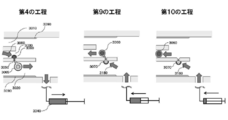
- the ninth step after the fusion of the first cell and the second cell is completed, the first suction port 2071 and the second suction port 2072 are closed, and suction is performed from the third suction port 2073 by the pump 2213. Then, the cytoplasm of the second cell is moved to the first cell.
- the first suction port 2071 and the second suction port 2072 are closed, and the pump 2213 sucks the first cell from the third suction port 2073 to separate the first cell from the second cell.
- the microscope 2100 is provided with the image recognition unit 2200
- the flow rate adjustment unit 2060 is provided with a valve
- the cell and the image recognition unit 2200 are used to adjust the valve and pump by the flow rate control unit 2220.
- the present invention can control the movement direction of the cytoplasm after fusion of cells and intermediates or cells by controlling the flow rate difference between the two flow paths, and without using a surfactant. Since separation / removal is possible, cell nucleus transplantation that has not been achieved by the conventional electric field concentration cell fusion method becomes possible.
- an additional third flow path for facilitating cell sorting is provided.
- the third channel has an opening in the first channel and includes a cell recovery unit. It is preferable that the first channel and the second channel are separated by a wall and provided substantially in parallel. Furthermore, a section connected to the first flow path and the second flow path, a fourth flow path connected to the section and having a predetermined angle with respect to the first flow path and the second flow path, A pump connected to the fourth flow path. It is preferable that at least one of the first channel, the second channel, and the fourth channel is linear.
- the present embodiment will be specifically described with reference to FIG. 5, but it is needless to say that the present invention is not limited to this embodiment.
- a third channel 2310 having an opening 2330 in the vicinity of the hole 2050 can be provided in the first channel 3010.
- the opening 2330 has a cell nucleus of the first cell, and has a size through which a cell including the cell membrane of the first cell and the cytoplasm of the second cell (hereinafter referred to as cytoplasm exchange cell) can pass.
- the minimum width or minimum diameter may be appropriately adjusted depending on the size of the cytoplasm-exchanged cell, but is preferably 6 ⁇ m or more, more preferably 10 ⁇ m or more, and further preferably 20 ⁇ m or more.
- the minimum width or minimum diameter of the opening 2330 may be smaller than the diameter of the cytoplasm exchange cell as long as the cytoplasm exchange cell can pass through.
- the cells are distorted and the third When cells are introduced into the flow path 2310, the cytoplasm-exchanged cells that have once entered the third flow path 2310 are unlikely to flow back out of the flow path.
- the third channel 2310 is connected to the cell recovery unit 2340 at the other end, and the cytoplasm-exchanged cells produced through the holes 2050 are sent to the third channel 2310 and recovered by the cell recovery unit 2340.
- a section 2320 connected to the first flow path 3010 and the second flow path 3020 is provided, and further connected to the section 2320 and predetermined with respect to the first flow path 3010 and the second flow path 3020.
- a pump 2350 connected to the fourth flow path 2360 is provided.
- the predetermined angle (defined as the smaller one of the two angles) formed by the fourth channel 2360 and the first channel 3010 or the second channel 3020 is not particularly limited as long as it is less than 180 °. However, it is preferably less than 150 °, more preferably less than 130 °, even more preferably less than 110 °, more preferably 30 ° or more, and more preferably 60 ° or more. Preferably, it is 90 ° or more.
- the angle formed by the fourth flow path 2360 and the first flow path 3010 and the fourth flow path 2360 and the second flow path 3020 are substantially equal.
- the suction and discharge of the pump 2350 allows the inside of the first flow path 3010 and the second flow path.
- a slight difference occurs in the flow between the inside of 3030, and when sucking, the flow of the second flow path 3020 becomes faster than the flow of the first flow path 3010, and when discharging, the flow of the first flow path 3010 The flow becomes faster than the flow of the second flow path 3020.
- FIG. 6 shows the vicinity of the first flow path 3010, the second flow path 3020, the third flow path 3030, and the hole 3050 provided in the wall separating the first flow path 3010 and the second flow path 3020.
- Electrodes 3090 are provided on both sides of the first flow path 3010 and the second flow path 3020 that run in parallel.
- the steps from the first step to the eighth step are the same as those in FIGS. 1-1 to 1-8.
- the fourth step as shown in FIG. 6, when suction is performed by one pump 3040, a part 3080 of the flow in the first flow path 3010 is passed through the hole 3050. Since it goes to the second flow path 3020, the flow of the second flow path 3020 is faster than the flow of the first flow path 3010, and as a result, the cytoplasm of the first cell 3060 can be moved to the intermediate 3065. It becomes possible. Then, the intermediate body 3065 that has received the cytoplasm can be selectively pulled by continuously sucking, and the intermediate body 3065 that has received the cytoplasm is separated from the first cell 3060 in the fifth step.
- the flow in the first flow path 3010 and the second flow path 3020 is reversed, and the second flow Since a portion 3180 of the flow in the channel 3020 goes to the first flow path 3010 via the hole 3050, the flow of the first flow path 3010 is faster than the flow of the second flow path 3020, and as a result, The cytoplasm of the second cell 3070 can be moved to the first cell 3060.
- the first cell 3060 that has received the cytoplasm can be selectively pulled by continuously aspirating, and the first cell 3060 that has received the cytoplasm is separated from the second cell 3070 in the tenth step. To do. Finally, the first cell 3060 can be recovered from the cell recovery unit 2340 to the outside of the flow path.
- Example 1 the cytoplasm of Jurkat cells was transplanted into another Jurkat cell from which the cytoplasm was removed.
- the apparatus used is as follows.
- the cell suspension (containing cell A) of the centrifuge tube A is added to the cell supply port A on the PDMS device as shown in FIG. 2, and the cell suspension (centrifuge tube B) is added to the sampling port B which is the cell supply port ( Cell B containing) was added.
- the cell suspension was aspirated with Pipetteman 1, and each cell was guided onto the cell fusion pathway (FIG. 4-1).
- Cells A and B were guided into the cell fusion pathway by the dielectrophoretic force generated by applying alternating current, and a pair of cells A and B was formed across the cell fusion pathway (FIGS. 4-2 to 4, 2: phase difference; 3 To 4: fluorescent field). While applying the pulse once or more, the pulse application process was observed with the phase difference and the fluorescence field to confirm the movement of the fluorescent dye due to cell fusion (FIGS. 4-5).
- Example 2 the cytoplasm of iPS cells was transplanted into fibroblasts from which the cytoplasm had been removed. That is, iPS cells (stained with Calcein AM and Hoechst33342) were used in place of cell A in Example 1, and fibroblasts (stained with Calcein red-orange and Hoechs33342) were used in place of cell B in Example 1.
- iPS cells stained with Calcein AM and Hoechst33342
- fibroblasts stained with Calcein red-orange and Hoechs33342
- Example 3 the cytoplasm of Jurkat cells was transplanted into iPS cells from which cytoplasm was removed under the same experimental conditions as in Example 1. Specifically, Jurkat cell suspension (1 ⁇ 10 6 cells / mL, DMEM + 10% FBS) and iPS cell suspension (1 ⁇ 10 6 cells / mL, mTeSRTM1) were added to each of two 15 mL centrifuge tubes. 1 ⁇ L of Calcein AM was added to the centrifuge tube A, 1 ⁇ L of Calcein red-orange and 1 ⁇ L of Hoechst33342 were added to the other centrifuge tube B, and incubated at 37 ° C. for 3 minutes to stain the cytoplasm and cell nucleus.
- the centrifuge tube was centrifuged at 600 rpm and 1000 rpm for 2 minutes, respectively, and then the supernatant was removed.
- 1 mL of a cell fusion buffer 200 mM sorbitol, 1 mM calcium acetate, 0.5 mM magnesium acetate, 1 mg / mL bovine serum albumin
- the centrifuge tube was centrifuged again under the same conditions as described above to precipitate live cells, and 1 mL of the supernatant was removed. This cell washing step was repeated two more times.
- 150 ⁇ L of cell fusion buffer was added and mixed to obtain a cell suspension for cell fusion.
- a cell suspension of iPS cells was added to the cell supply unit 2010, and a cell suspension of Jurkat cells was added to the cell supply unit 2020.
- Pipetman was used as the pump 2350.
- each cell could be introduced into the channel (FIG. 7-1).
- a cell pair was formed by sandwiching the cell fusion pathway between the iPS cells and the Jurkat cells by the dielectrophoretic force by applying alternating current (FIG. 7-1: phase difference; FIG. 7-2: fluorescence field). While applying the pulse one or more times, the pulse application process was observed with the phase difference and the fluorescence field to confirm the movement of the fluorescent dye due to cell fusion (FIG. 7-3: fluorescence field).
- ⁇ Recovering cell nuclei> The application of alternating current was stopped, and the cytoplasm of iPS cells was moved to Jurkat cells by aspiration with Pipetteman (FIG. 7-4). Subsequently, Jurkat cells were separated from iPS cells by aspiration with a pipetteman (FIG. 7-5). To maintain iPS cells in the cell fusion pathway, alternating current was applied again to maintain the nuclei of iPS cells in the pores.
- ⁇ Second cell fusion> The cell suspension was again aspirated with a pipetman, and another Jurkat cell was introduced onto the cell fusion pathway (FIGS. 7-6).
- Jurkat cells were guided into the cell fusion pathway by the dielectrophoretic force by application of alternating current, and a pair of iPS cells and Jurkat cells were formed across the cell fusion pathway (FIG. 7-6: phase difference; FIG. 7-7: fluorescence) Field of view). While applying the pulse one or more times, the pulse application process was observed with a phase difference and a fluorescence field, and movement of the fluorescent dye due to cell fusion was confirmed (FIGS. 7-8).
- ⁇ Transplantation of cytoplasm> The application of alternating current was stopped, and the cytoplasm of Jurkat cells was transferred to iPS cells by discharging with Pipetteman. Subsequently, iPS cells were separated from Jurkat cells by continuing to discharge with Pipetteman (FIGS. 7-10). The separated iPS cells can be recovered from the cell recovery port to the outside of the channel via the cell recovery channel. As a result, the same effect as that obtained when the cell nucleus of the iPS cell was transplanted into the cytoplasm of the Jurkat cell was obtained in relation to the cytoplasm.
- the present invention can provide an apparatus for exchanging cell nuclei.
Landscapes
- Life Sciences & Earth Sciences (AREA)
- Chemical & Material Sciences (AREA)
- Engineering & Computer Science (AREA)
- Bioinformatics & Cheminformatics (AREA)
- Health & Medical Sciences (AREA)
- Wood Science & Technology (AREA)
- Biotechnology (AREA)
- Organic Chemistry (AREA)
- Zoology (AREA)
- Microbiology (AREA)
- Sustainable Development (AREA)
- Biomedical Technology (AREA)
- Biochemistry (AREA)
- General Engineering & Computer Science (AREA)
- General Health & Medical Sciences (AREA)
- Genetics & Genomics (AREA)
- Medicinal Chemistry (AREA)
- Apparatus Associated With Microorganisms And Enzymes (AREA)
- Micro-Organisms Or Cultivation Processes Thereof (AREA)
Abstract
本発明は、細胞核を交換するための装置を提供することを目的とする。細胞核の交換装置は、第1の細胞の細胞核を有し、前記第1の細胞の細胞膜と第2の細胞の細胞質とを含む細胞の製造装置であって、壁で隔てられた、実質的に平行な第1の流路及び第2の流路と、前記第1の流路及び前記第2の流路のそれぞれに接続する細胞供給部と、前記壁に設けられた孔と、前記孔を挟んで設けられた電極と、直流交流信号発生装置と、前記第1の流路内に設けられ、開口部を有する第3の流路と、前記第3の流路に接続する細胞回収部と、前記第1の流路と前記第2の流路とに繋がる区画と、前記区画に接続し、前記第1の流路と前記第2の流路に対して所定の角度を有する第4の流路と、前記第4の流路に接続するポンプと、を備える。
Description
本発明は、細胞質交換装置に関する。
ある細胞の細胞核を別の細胞の細胞質内へ移植する細胞核移植は、細胞の性質を変える方法として医療や産業に重要な役割を果たしている。
例えば、細胞核を除去した受精卵に、別個体の体細胞由来の核を移植した後、その受精卵を子宮に戻すことでクローン個体を産出する方法や、子宮に戻さず体外で胚盤胞へ発生させて胚性幹細胞 (Embryonic Stem cells: ES細胞) を樹立する体細胞由来胚性幹細胞(nuclear transfer Embryonic stem cells: NtES細胞) 樹立方法などがある。こうして得られたクローン個体やNtES細胞は、畜産や再生医療に発展する基礎研究に寄与している。
細胞の性質を変える技術には、核移植以外にも、センダイウイルス法やプロトプラスト-ポリエチレングリコール法、電気的細胞融合法、電界集中細胞融合法などの細胞融合技術がある。これは、2つ以上の細胞を融合させ、1つの細胞を形成する技術である。この方法では、細胞融合後の1つの細胞内には2つ以上の細胞に由来する細胞核と細胞質が存在する。
細胞融合技術のうち、電界集中型細胞融合法は、2つの細胞を、細胞核の直径以下の幅や径のスリットや孔(オリフィス) を介して接触させ、スリットやオリフィスでパルス的に電界を集中させることで、2つの細胞膜の接点で電気的に細胞膜が部分的に破壊され、復元する過程で細胞を融合する方法である(特開2009-178105号公報;特開2007-174901号公報)。この方法では、オリフィスや流路の最大径や最大幅が細胞核径より小さいことにより、細胞核の混合を防ぐことが可能である(例えば、特許文献1、2参照)。近年、Polydimethyl siloxane (PDMS)を使用して作製された様々な流路を用いて細胞融合法が検討されている。例えば、PDMSで製造された2つの平行流路間をオリフィスのみで繋ぎ、各流路末端に細胞供給口と吸引口をそれぞれ設けた流路を用い、オリフィスで細胞対を形成後、細胞融合させる方法がある。例えば、細胞供給口にJurkat細胞または樹状細胞を導入し、吸引口方向へ流路上で細胞を移動させ、オリフィスでJurkat細胞と樹状細胞を融合させ、Jurkat細胞の細胞質を樹状細胞へ移動させた後、界面活性剤を添加し、Jurkat細胞側の流路に流れを生じさせて両細胞を切り離すことで、細胞質が移動できるようになった(Cytoplasmic transfer without nuclei mixing between dendritic cells and tumor cells achieved by one to-one electrofusion via micro-orifices in a microfluidic device. 18th International Conference on Miniaturized. Systems for Chemistry and Life Sciences. October 26-30, 2014, San Antonio, Texas, USA)。
本発明は、細胞核を交換するための装置を提供することを目的とする。
本発明の一実施態様は、第1の細胞の細胞核を有し、前記第1の細胞の細胞膜と第2の細胞の細胞質とを含む細胞の製造装置であって、壁で隔てられた、実質的に平行な第1の流路及び第2の流路と、前記第1の流路及び前記第2の流路のそれぞれに接続する細胞供給部と、前記壁に設けられた孔と、前記孔を挟んで設けられた電極と、直流交流信号発生装置と、前記第1の流路内に設けられ、開口部を有する第3の流路と、前記第3の流路に接続する細胞回収部と、前記第1の流路と前記第2の流路とに繋がる区画と、前記区画に接続し、前記第1の流路または前記第2の流路に対して所定の角度を有する第4の流路と、前記第4の流路に接続するポンプと、を備える製造装置である。前記第3の流路は、第1の流路内に前記第1の流路の長軸に沿って実質的に平行に設けられてもよい。前記開口部は、前記第1の細胞の細胞核を有し、前記第1の細胞の細胞膜と前記第2の細胞の細胞質とを含む細胞が通過できる大きさであってもよい。前記孔の最大幅または最大径は、前記第1の細胞の細胞核の径よりも小さくてもよい。前記孔の最大幅または最大径は6μm以下であってもよい。前記所定の角度が、90°以上110°未満であってもよい。ポンプが一つだけ設けられていてもよい。第1の流路、第2の流路、及び第4の流路のうち、少なくとも一つが直線状であってもよい。
==関連文献とのクロスリファレンス==
本出願は、2018年2月13日付で出願した日本国特許出願2018-023387に基づく優先権を主張するものであり、当該基礎出願を引用することにより、本明細書に含めるものとする。
本出願は、2018年2月13日付で出願した日本国特許出願2018-023387に基づく優先権を主張するものであり、当該基礎出願を引用することにより、本明細書に含めるものとする。
以下、実施例を挙げながら、本発明の実施形態を詳細に述べる。
本発明の目的、特徴、利点、及びそのアイデアは、本明細書の記載により、当業者には明らかであり、本明細書の記載から、当業者であれば、容易に本発明を再現できる。以下に記載された発明の実施の形態及び具体的に実施例などは、本発明の好ましい実施態様を示すものであり、例示又は説明のために示されているのであって、本発明をそれらに限定するものではない。本明細書で開示されている本発明の意図並びに範囲内で、本明細書の記載に基づき、様々な改変並びに修飾ができることは、当業者にとって明らかである。
==細胞質の交換方法==
本発明の一実施形態に係る第1の細胞の細胞質の交換方法は、第1の細胞の細胞質を除去する第1の工程と、第2の細胞の細胞質を第1の細胞へ導入する第2の工程を含む、細胞質の交換方法であって、
(1)第1の工程の後で第2の工程が行われる、または
(2)第1の細胞の細胞質の40%~60%と、第2の細胞の細胞質の40%~60%とが交換される第1の細胞質交換工程によって、第1の工程と第2の工程が同時に行われる、方法である。
本発明の一実施形態に係る第1の細胞の細胞質の交換方法は、第1の細胞の細胞質を除去する第1の工程と、第2の細胞の細胞質を第1の細胞へ導入する第2の工程を含む、細胞質の交換方法であって、
(1)第1の工程の後で第2の工程が行われる、または
(2)第1の細胞の細胞質の40%~60%と、第2の細胞の細胞質の40%~60%とが交換される第1の細胞質交換工程によって、第1の工程と第2の工程が同時に行われる、方法である。
(2)の場合、細胞質交換工程後の第1の細胞の細胞質の40%~60%と、新たな第2の細胞の細胞質の40%~60%とが交換される第2の細胞質交換工程がさらに行われてもよく、この第2の細胞質交換工程がさらに1回以上行われてもよい。この工程を繰り返すことによって、第1の細胞の細胞質が第2の細胞の細胞質に交換される割合が高くなる。本発明の一実施形態に係る細胞質の交換方法を用いて、第1の細胞の細胞核を有し、第2の細胞の細胞核を有さず、第1の細胞の細胞膜と第2の細胞の細胞質とを含む細胞を製造することができる。こうして製造された細胞において、第1の細胞の細胞膜の割合は特に限定されないが、50%以上であることが好ましく、60%以上であることがより好ましく、70%以上であることがさらに好ましく、80%以上であることがさらに好ましく、90%以上であることがさらに好ましく、95%以上であることがさらに好ましい。また、第2の細胞の細胞質の割合は特に限定されないが、50%以上であることが好ましく、60%以上であることがより好ましく、70%以上であることがさらに好ましく、80%以上であることがさらに好ましく、90%以上であることがさらに好ましく、95%以上であることがさらに好ましい。
以下、上記交換方法を用いて、細胞を製造する実施態様を詳細に説明する。
<実施形態I>
ここでは、図1を用いて、上記交換方法(1)を用いて行われる、本発明の一実施形態に係る細胞の製造方法を具体的に説明するが、本発明は本実施形態に限定されない。本実施形態では、第1の流路と第2の流路を備え、第1の流路の壁と第2の流路の壁は孔で連通している流路を用い、第1の細胞の細胞核を有し、第2の細胞の細胞核を有さず、第1の細胞の細胞膜と第2の細胞の細胞質とを含む細胞を製造する。
ここでは、図1を用いて、上記交換方法(1)を用いて行われる、本発明の一実施形態に係る細胞の製造方法を具体的に説明するが、本発明は本実施形態に限定されない。本実施形態では、第1の流路と第2の流路を備え、第1の流路の壁と第2の流路の壁は孔で連通している流路を用い、第1の細胞の細胞核を有し、第2の細胞の細胞核を有さず、第1の細胞の細胞膜と第2の細胞の細胞質とを含む細胞を製造する。
第1の工程として、まず、第1の流路にあって、残したい細胞核1010と、除去したい細胞質1020と、細胞膜1025と、を有する第1の細胞1030と、第2の流路にある中間体1040を、流路中の溶液の流れ1050によって、両方の流路の壁を貫通して設けられた孔1080の入り口を構成するそれぞれの孔近傍に誘導する(図1-1)。必要に応じて交流1060電界を発生させ、その中で細胞を誘導してもよい。流路の壁は絶縁体1070で構成されるのが好ましい。第1の流路内の流れ1050と第2の流路内の流れ1050の方向は特に限定されないが、実質的に平行であることが好ましい。溶液は、細胞を生きた状態で操作できるものであれば特に限定されず、例えば生理食塩水や細胞培養用培地などを例示できる。中間体は特に限定されず、対になった細胞と融合して細胞の細胞質を受け入れられるものであればよいが、具体的な例としては、細胞やリポソームが例示できる。細胞である場合、第1の細胞または第2の細胞と同じ種類であっても異なる種類であってもよい。孔1080の形状は特に限定されず、スリット状、円状、長円状であってもよく、壁の厚みと同じ深さを有するため、厚い壁の場合は流路状であってもよい。
第2の工程として、誘電泳動力により、孔1080を挟んで第1の細胞1030と中間体1040の第1の対を形成させる(図1-2)。誘電泳動力は、交流1060印加による電界集中により流路の壁で生じる。
第3の工程として、第1の対に電圧を印加1090することで、第1の細胞1030と中間体1040とを融合して第1の融合細胞1100を作製する (図1-3)。この時印加する電圧は、従来細胞融合に用いられることが知られている強さとすることができるが、0.1~50Vであることが好ましく、0.5V~20Vであることがより好ましく、1~10Vであることがさらに好ましく、1~3Vであることがさらに好ましく、約2Vであることがさらに好ましい。また印加する時間は、特に限定されないが、1μsec~1msecであることが好ましく、1μsec~500μsecであることがより好ましく、1μsec~100μsecであることがさらに好ましいが、可能な限り短い時間であることがより好ましい。中間体1040が細胞である場合、本工程では、細胞融合後、第1の細胞1030と中間体1040の細胞質がお互いに混入する。
第4の工程として、第1の細胞1030の細胞質1020を中間体1040へ移動させる(図1-4)。この細胞質1020の移動は、例えば、第2の流路内の流れ1120の速度を、第1の流路内の流れ1110の速度より大きくし、その流速差を利用することにより行うことができる。このとき、第1の流路内の流れ1110の流速は0、つまり第1の流路内に流れのない状態であってもよい。第1の流路内の流れ1110と第2の流路内の流れ1120の方向は特に限定されないが、実質的に平行であることが好ましい。ここで、孔1080の最大幅または最大径を、第1の細胞の核の径より小さくしておくことにより、第1の細胞1030の細胞核1010は、孔1080を通過できずに第1の流路内に残る。具体的には、孔1080の最大幅または最大径は、第1の細胞1030の種類によって適宜調整すればよいが、20μm以下であることが好ましく、10μm以下であることがより好ましく、6μm以下であることがさらに好ましい。なお、移動させる細胞質の割合は特に限定されないが、50%以上であることが好ましく、60%以上であることがより好ましく、70%以上であることがさらに好ましく、80%以上であることがさらに好ましく、90%以上であることがさらに好ましく、95%以上であることがさらに好ましい。
第5の工程として、第1の細胞1030と中間体104を切り離す(図1-5)。第1の細胞1035を孔1080の入り口で保持しながら、細胞質1020を受け取った中間体1045を切り離すのが好ましい。この切り離しは、例えば、第2の流路内の流れ1120の速度を、第1の流路内の流れ1110の速度より大きくし、その流速差を利用することにより行うことができる。第1の流路内の流れ1110の流速は0、つまり第1の流路内に流れのない状態であってもよい。
このように、本実施形態では、第1の工程から第5の工程までの工程において、中間体を用いることにより、第1の細胞の細胞質を除去することができる。
第6の工程として、第1の細胞1030に移植したい細胞質1130と、必要のない細胞核1140を有する第2の細胞1150を、流れ1050により、孔1080の入り口を構成する、第2の流路側の孔近傍に誘導する (図1-6)。必要に応じて交流1060電界を発生させ、その中で細胞を誘導してもよい。
第7の工程として、誘電泳動力により、孔1080を挟んで第1の細胞1030と第2の細胞1150の第2の対を形成させる (図1-7)。誘電泳動力は、交流1060印加による電界集中により流路の壁で生じる。
第8の工程として、第2の対に電圧を印加1090することで第1の細胞1030と第2の細胞1150を融合して第2の融合細胞1160を作製する (図1-8)。この時印加する電圧は、従来細胞融合に用いられることが知られている強さであればよいが、1~10Vであることが好ましく、2Vであることがさらに好ましい。また印加する時間は、100μsecであることが好ましく、100μsec以下で可能な限り短い時間であることがさらに好ましい。
第9の工程として、第2の細胞1150の細胞質1130を第1の細胞1035へ移動させる (図1-9)。この移動は、例えば、第1の流路内の流れ1110の速度を、第2の流路内の流れ1120の速度より大きくし、その流速差を利用することにより行うことができる。第2の流路内の流れ1120の流速は0、つまり第2の流路内に流れのない状態であってもよい。ここで、孔1080の最大幅または最大径を、第2の細胞の核の径より小さくしておくことにより、第2の細胞1150の細胞核1140は、孔1080を通過できずに第2の流路内に残る。具体的には、孔1080の最大幅または最大径は、第2の細胞1150の種類によって適宜調整すればよいが、20μm以下であることが好ましく、10μm以下であることがより好ましく、6μm以下であることがさらに好ましい。なお、移動させる細胞質の割合は特に限定されないが、50%以上であることが好ましく、60%以上であることがより好ましく、70%以上であることがさらに好ましく、80%以上であることがさらに好ましく、90%以上であることがさらに好ましく、95%以上であることがさらに好ましい。
第10の工程として、第1の細胞1030を、第2の細胞1150から切り離す (図1-10)。こうして、第1の細胞1030の細胞質1020を、第2の細胞1150の細胞質1130に交換することによって、第1の細胞1030の細胞核1010を有し、第2の細胞1150の細胞核1140を有さず、第1の細胞1030の細胞膜1025と第2の細胞1150の細胞質1130とを含む細胞1170の製造が完了する。
このように、第6の工程から第10の工程までの工程によって、第2の細胞の細胞質を第1の細胞へ導入することができる。
本方法において、第1の細胞1030と第2の細胞1150の細胞種は特に限定されないが、第1の細胞1030は体細胞であることが好ましく、線維芽細胞または血球細胞であることがさらに好ましい。また、第2の細胞1150は幹細胞であることが好ましく、iPS細胞、ES細胞、神経幹細胞、上皮幹細胞、肝幹細胞、生殖幹細胞、造血幹細胞、間葉幹細胞、骨格筋幹細胞からなる群から選択されるのがさらに好ましい。第1の細胞1030は体細胞とし、第2の細胞1150を幹細胞とすることにより、例えば、幹細胞の細胞核を体細胞の細胞核に交換したことと同様の効果が得られる。
<実施形態II>
ここでは、上記交換方法(2)を用いて行われる、本発明の一実施形態に係る細胞の製造方法を具体的に説明するが、本発明は本実施形態に限定されない。本実施形態では、第1の流路と第2の流路を備え、第1の流路の壁と第2の流路の壁は孔で連通している流路を用い、第1の細胞の細胞核を有し、第2の細胞の細胞核を有さず、第1の細胞の細胞膜と第2の細胞の細胞質とを含む細胞を製造する。第1の工程から第3の工程は、実施形態Iに準じるが、中間体として、第2の細胞を用いる。第3の工程終了後、第1の細胞と第2の細胞の細胞質がお互いに混入する。このように、本実施形態では、第1の細胞の細胞質を除去する第1の工程と、第2の細胞の細胞質を第1の細胞へ導入する第2の工程が同時に行われる。この際に、第1の対を融合させたままで、長時間放置すると、第1の細胞と第2の細胞の間で細胞質が均一になるが、交換される細胞質の割合は特に限定されず、第1の細胞の細胞質の10%~25%と、第2の細胞の細胞質の10%~25%とが交換されることが好ましく、第1の細胞の細胞質の25%~40%と、第2の細胞の細胞質の25%~40%とが交換されることがより好ましく、第1の細胞の細胞質の40%~60%と、第2の細胞の細胞質の40%~60%とが交換されることがさらに好ましい。そして、その後、第1の細胞と中間体とを切り離す第5の工程を行う。第5の工程の詳細は、実施形態Iに準じる。
ここでは、上記交換方法(2)を用いて行われる、本発明の一実施形態に係る細胞の製造方法を具体的に説明するが、本発明は本実施形態に限定されない。本実施形態では、第1の流路と第2の流路を備え、第1の流路の壁と第2の流路の壁は孔で連通している流路を用い、第1の細胞の細胞核を有し、第2の細胞の細胞核を有さず、第1の細胞の細胞膜と第2の細胞の細胞質とを含む細胞を製造する。第1の工程から第3の工程は、実施形態Iに準じるが、中間体として、第2の細胞を用いる。第3の工程終了後、第1の細胞と第2の細胞の細胞質がお互いに混入する。このように、本実施形態では、第1の細胞の細胞質を除去する第1の工程と、第2の細胞の細胞質を第1の細胞へ導入する第2の工程が同時に行われる。この際に、第1の対を融合させたままで、長時間放置すると、第1の細胞と第2の細胞の間で細胞質が均一になるが、交換される細胞質の割合は特に限定されず、第1の細胞の細胞質の10%~25%と、第2の細胞の細胞質の10%~25%とが交換されることが好ましく、第1の細胞の細胞質の25%~40%と、第2の細胞の細胞質の25%~40%とが交換されることがより好ましく、第1の細胞の細胞質の40%~60%と、第2の細胞の細胞質の40%~60%とが交換されることがさらに好ましい。そして、その後、第1の細胞と中間体とを切り離す第5の工程を行う。第5の工程の詳細は、実施形態Iに準じる。
さらに、第2の流路において新たな第2の細胞を、前記孔に誘導する第11の工程と、誘電泳動力により、前記孔を介して、第1の細胞と第2の細胞との新たな第1の対を形成させる第12の工程と、第1の細胞と第2の細胞とを融合する第13の工程と、第1の細胞と第2の細胞とを切り離す第14の工程と、を行ってもよい。第11~14の工程の詳細は、実施形態Iの第1~3、5の工程に準じる。
この後、第11~14の工程をさらに1回以上、繰り返してもよいが、1回繰り返すことが好ましく、2回以上繰り返すことがより好ましく、5回以上繰り返すことがさらに好ましい。それによって、交換される細胞質の割合を高めることができるようになる。
==細胞質を交換するための装置==
以下、上記の方法を実行することができる本発明の装置の一実施態様を、図2(1)を用いて詳細に説明する。本発明の装置は、細胞の細胞質を交換するための装置であって、第1の流路2030及び第2の流路2040と、第1の流路2030及び第2の流路2040のそれぞれ接続する第1の細胞供給部2010と第2の細胞供給部2020と、第1の流路の壁と第2の流路の壁との間に設けられた孔2050と、孔2050を挟んで設けられた電極2080と、第1の流路2030及び第2の流路2040の流速を調節する流速調節部2060と、流速調節部2060に設けられた吸引路2070と、各吸引口2071,2072,2073に設けられたポンプ2211,2212,2213と、直流交流信号発生装置2090と、顕微鏡2100とを備える。第1の流路2030及び第2の流路2040は、実質的に平行に走っていることが好ましい。
以下、上記の方法を実行することができる本発明の装置の一実施態様を、図2(1)を用いて詳細に説明する。本発明の装置は、細胞の細胞質を交換するための装置であって、第1の流路2030及び第2の流路2040と、第1の流路2030及び第2の流路2040のそれぞれ接続する第1の細胞供給部2010と第2の細胞供給部2020と、第1の流路の壁と第2の流路の壁との間に設けられた孔2050と、孔2050を挟んで設けられた電極2080と、第1の流路2030及び第2の流路2040の流速を調節する流速調節部2060と、流速調節部2060に設けられた吸引路2070と、各吸引口2071,2072,2073に設けられたポンプ2211,2212,2213と、直流交流信号発生装置2090と、顕微鏡2100とを備える。第1の流路2030及び第2の流路2040は、実質的に平行に走っていることが好ましい。
<流路内を流れる溶液の流速の調節>
図2(2)(3)に、流速調節部2060の拡大図を示し、第1の流路2030及び第2の流路2040内の溶液の流速の調節方法を以下で説明する。
図2(2)(3)に、流速調節部2060の拡大図を示し、第1の流路2030及び第2の流路2040内の溶液の流速の調節方法を以下で説明する。
流路内を流れる溶液は、流速調節部2060によって、各吸引口2071,2072,2073への接続が調節される。そして、各吸引口2071,2072,2073に設けられたポンプ2211,2212,2213によって、独立に吸引される。吸引口2072,2073への溶液の流れを止め、吸引口2071で吸引すると、第1の流路2030と第2の流路2040の流れの方向と流速は同じになる。吸引口2071,2073への溶液の流れを止め、吸引口2072から吸引すると、流れの方向は同じだが、第2の流路2040の流れは流路壁とぶつかる事でわずかに流速は減少し、第1の流路2030の流れと比較して、流速差が生じる。逆に、吸引口2071,2072への溶液の流れを止め、吸引口2073から吸引すると、流れの方向は同じだが、第1の流路2030の流れは流路壁とぶつかる事でわずかに流速は減少し、第2の流路2040の流れと比較して、流速差が生じる。ここで、流速調節部2060に弁(例えば電磁弁など)を設けることによって、さらに流速の細かな制御が可能になる。
<追加の実施形態 弁の構成>
弁の構成例を図2(1)を参照しながら、以下に説明する。
弁の構成例を図2(1)を参照しながら、以下に説明する。
まず、弁を流速調節部2060内で、各吸引口2071、2072、2073に繋がる吸引路2070に設置することができる。それによって、各吸引口2071、2072、2073に向かう溶液の流れを独立に調節できるようになる。
また、他の実施形態として、吸引路2070を流速調節部2060の下流で第1の吸引口2071の上流の吸引路2070に接続させた、新たな吸引路2074(2070)(図2(1)では点線で示した。)を設け、ポンプ2212,2213を除去する。この場合この実施例では、吸引口2071に接続されたポンプ2211のみで、第1の流路2030及び第2の流路2040内の溶液の流速を制御することが可能となる。
<追加の実施形態 圧力緩衝部>
孔2050は、図1で詳細に説明した物に準じる。
孔2050は、図1で詳細に説明した物に準じる。
図3(1)に示すように、孔2050と吸引口2071、2072、2073間に圧力緩衝部2110を設けてもよい。これによって、吸引による急激な流速変化を緩和することができ、安定的に細胞質の移動と細胞の分離が可能になる。
<追加の実施形態 画像認識部>
図3(2)に示すように、顕微鏡2100に、顕微鏡像を映し出す画像認識部2200を設け、画像認識部2200とポンプ2210に、流速制御装置2220を設けてもよい。これによって、効率的に細胞質の移動と細胞の分離が可能になる。この流速制御装置2220は、上述した弁(電磁弁)弁を調節してもよい。
図3(2)に示すように、顕微鏡2100に、顕微鏡像を映し出す画像認識部2200を設け、画像認識部2200とポンプ2210に、流速制御装置2220を設けてもよい。これによって、効率的に細胞質の移動と細胞の分離が可能になる。この流速制御装置2220は、上述した弁(電磁弁)弁を調節してもよい。
==細胞質を交換するための装置の使用方法==
以下、本発明の一実施態様にかかる上記装置を用い、細胞質を交換するための使用方法と、それによる新規細胞の製造方法を詳細に説明する。
以下、本発明の一実施態様にかかる上記装置を用い、細胞質を交換するための使用方法と、それによる新規細胞の製造方法を詳細に説明する。
第1の工程として、第2の吸引口2072及び第3の吸引口2073を閉止し、第1の細胞供給部2010内の第1の細胞と、第2の細胞供給部2020内の中間体を、第1の吸引口2071からポンプ2211で吸引することで、細胞を孔2050の入り口を構成するそれぞれの孔近傍へ誘導する。
第2の工程として、直流交流信号発生制御装置2090で発生させた交流電界中の誘電泳動力により、孔2050を介して、第1の細胞と中間体との第1の対を形成させる。
第3の工程として、直流交流信号発生制御装置2090で、第1の対へ電圧を印加することで第1の細胞と中間体とを融合する。
第4の工程として、第1の細胞と中間体との融合の完了後、第1の吸引口2071及び第3の吸引口2073を閉止し、ポンプ2212で第2の吸引口2072から吸引して、第1の細胞の細胞質を中間体へ移動させる。
第5の工程として、直流交流信号発生制御装置2090で発生させた誘電泳動力で第1の細胞を孔2050で保持しながら、第1の吸引口2071及び第3の吸引口2073を閉止し、ポンプ2212で第2の吸引口2072から吸引して、第1の細胞から中間体を切り離す。
第6の工程として、第2の吸引口2072及び第3の吸引口2073を閉止し、第1の吸引口2071からポンプ2211で吸引することで、第2の細胞供給部2020内の第2の細胞を孔2050の入り口を構成する孔近傍へ誘導する。ここで、第3の細胞供給部を設け、第2の細胞供給部2020を中間体用にし、第3の細胞供給部を第2の細胞用にしてもよい。
第7の工程として、直流交流信号発生制御装置2090で発生させた交流電界中の誘電泳動力により、孔2050を介して、第1の細胞と第2の細胞の第2の対を形成させる。
第8の工程として、直流交流信号発生制御装置2090で、第2の対へ電圧を印加することで、第1の細胞と第2の細胞を融合する。
第9の工程として、第1の細胞と第2の細胞の融合の完了後、第1の吸引口2071及び第2の吸引口2072を閉止し、ポンプ2213で、第3の吸引口2073から吸引して、第1の細胞へ第2の細胞の細胞質を移動させる。
第10の工程として、第1の吸引口2071及び第2の吸引口2072を閉止し、ポンプ2213で、第3の吸引口2073から吸引して、第1の細胞を第2の細胞から切り離す。
装置構成において述べたように、顕微鏡2100に画像認識部2200を設け、流速調節部2060に弁を設け、細胞を画像認識部2200で分析しながら、流速制御装置2220によって弁及びポンプを調節することによって溶液の流速を調節することで、効率よく本法を実施することが可能になる。
このように、本発明は、2つの流路における流速差を制御することで、細胞と中間体あるいは細胞同士の融合後の細胞質の移動方向を制御でき、かつ、界面活性剤を使わず細胞の分離・除去が可能となるため、従来の電界集中細胞融合法では達成されなかった細胞核移植が可能になる。
==ポンプを一つにした細胞質交換装置==
本実施形態では、細胞の選別を容易にするための追加の第3の流路を設ける。第3の流路は、第1の流路に開口部を有し、細胞回収部を備える。第1の流路と第2の流路は壁で隔てられて、実質的に平行に設けることが好ましい。さらに、第1の流路と第2の流路とに繋がる区画と、区画に接続し、第1の流路と第2の流路に対して所定の角度を有する第4の流路と、第4の流路に接続するポンプと、を設ける。第1の流路、第2の流路、及び第4の流路のうち、少なくとも一つが直線状であることが好ましい。
以下、図5を参照しながら、本実施形態を具体的に説明するが、本発明は、この実施形態に限られないことは言うまでもない。
本実施形態では、細胞の選別を容易にするための追加の第3の流路を設ける。第3の流路は、第1の流路に開口部を有し、細胞回収部を備える。第1の流路と第2の流路は壁で隔てられて、実質的に平行に設けることが好ましい。さらに、第1の流路と第2の流路とに繋がる区画と、区画に接続し、第1の流路と第2の流路に対して所定の角度を有する第4の流路と、第4の流路に接続するポンプと、を設ける。第1の流路、第2の流路、及び第4の流路のうち、少なくとも一つが直線状であることが好ましい。
以下、図5を参照しながら、本実施形態を具体的に説明するが、本発明は、この実施形態に限られないことは言うまでもない。
図5に示すように、孔2050の近傍に開口部2330を有する第3の流路2310を、第1の流路3010に設けることができる。開口部2330は第1の細胞の細胞核を有し、第1の細胞の細胞膜と第2の細胞の細胞質とを含む細胞(以下、細胞質交換細胞と称する)が通過できる大きさであって、その最小幅または最小径は、細胞質交換細胞の大きさによって適宜調整すればよいが、例えば、6μm以上であることが好ましく、10μm以上であることがより好ましく、20μm以上であることがさらに好ましい。開口部2330の最小幅または最小径は、細胞質交換細胞が通過できるのであれば、細胞質交換細胞の直径よりも小さくてもよい。実際、開口部2330の最小幅または最小径を細胞質交換細胞の直径よりも若干小さくしておき、第3の流路2310内の溶液の流速を早くすることによって、細胞を歪ませて第3の流路2310内へ細胞を導入するようにすると、一旦第3の流路2310に入った細胞質交換細胞は流路外に逆流しにくくなる。第3の流路2310は、もう一端で細胞回収部2340に接続されており、孔2050を通じて作製された細胞質交換細胞を、第3の流路2310に送り込んで、細胞回収部2340で回収することにより、細胞質の交換処理をされていない細胞や処理途中の細胞から、細胞質交換細胞を分離して回収することが容易になる。
次に、第1の流路3010と、第2の流路3020とに繋がる区画2320を設け、さらに、区画2320に接続し、第1の流路3010と第2の流路3020に対して所定の角度を有する第4の流路2360と、第4の流路2360に接続するポンプ2350を設ける。第4の流路2360と第1の流路3010または第2の流路3020のなす所定の角度(二つある角度のうち、小さい方と規定する)は、180°未満であれば特に限定されないが、150°未満であることが好ましく、130°未満であることがより好ましく、110°未満であることがさらに好ましく、また、30°以上であることが好ましく、60°以上であることがより好ましく、90°以上であることがさらに好ましい。第1の流路3010及び第2の流路3020は実質的に平行であるから、第4の流路2360と第1の流路3010のなす角度、及び第4の流路2360と第2の流路3020のなす角度はほぼ等しくなる。
第4の流路2360と第1の流路3010または第2の流路3020を所定の角度にすることより、ポンプ2350の吸引と吐出によって、第1の流路3010内と第2の流路3020内とで流れにわずかな差が生じ、吸引するときは、第2の流路3020の流れが第1の流路3010の流れより速くなり、吐出するときは、第1の流路3010の流れが第2の流路3020の流れより速くなる。
第4の流路2360と第1の流路3010または第2の流路3020を所定の角度にすることより、ポンプ2350の吸引と吐出によって、第1の流路3010内と第2の流路3020内とで流れにわずかな差が生じ、吸引するときは、第2の流路3020の流れが第1の流路3010の流れより速くなり、吐出するときは、第1の流路3010の流れが第2の流路3020の流れより速くなる。
以下、図6を参照しながら、本実施形態の装置を用いた細胞質の交換方法について説明する。図6は、第1の流路3010、第2の流路3020、第3の流路3030、及び第1の流路3010と第2の流路3020を隔てる壁に設けられた孔3050の近傍を拡大した図である。平行に走る第1の流路3010と第2の流路3020の両側に電極3090が設けられている。
まず、第1の工程から第8の工程までは、図1-1から図1-8の説明に準じる。なお、本実施形態では、第4の工程においては、図6に示すように、1個のポンプ3040で吸引すると、第1の流路3010内の流れの一部3080が、孔3050を介して第2の流路3020へ向かうため、第2の流路3020の流れは第1の流路3010の流れより速くなり、結果として、第1の細胞3060の細胞質を中間体3065へ移動させることが可能になる。そして、引き続き吸引することにより、細胞質を受け取った中間体3065を選択的に引っ張ることができ、第5の工程において、細胞質を受け取った中間体3065が第1の細胞3060から分離する。
本実施形態の第9の工程では、図5に示すように、1個のポンプ3040で吐出すると、第1の流路3010及び第2の流路3020内の流れが逆転し、第2の流路3020内の流れの一部3180が、孔3050を介して第1の流路3010へ向かうため、第1の流路3010の流れは第2の流路3020の流れより速くなり、結果として、第2の細胞3070の細胞質を第1の細胞3060へ移動させることが可能になる。
そして、引き続き吸引することにより、細胞質を受け取った第1の細胞3060を選択的に引っ張ることができて、第10の工程において、細胞質を受け取った第1の細胞3060が第2の細胞3070から分離する。最終的に、第1の細胞3060を細胞回収部2340から流路外へ回収できる。
(実施例1)
本実施例では、Jurkat細胞の細胞質を、細胞質を除去した別のJurkat細胞内へ移植した。用いた装置は、以下の通りである。
本実施例では、Jurkat細胞の細胞質を、細胞質を除去した別のJurkat細胞内へ移植した。用いた装置は、以下の通りである。
・ファンクションジェネレーター
交流印加条件:周波数1MHz、電圧5V
パルス印加条件:時間100μs、電圧10V
・デジタルオシロスコープ
・バイポーラ電力増幅装置
・位相差・蛍光顕微鏡
交流印加条件:周波数1MHz、電圧5V
パルス印加条件:時間100μs、電圧10V
・デジタルオシロスコープ
・バイポーラ電力増幅装置
・位相差・蛍光顕微鏡
また、蛍光染色試薬は、以下のものを用いた。
・使用蛍光染色試薬:
・Calcein, AM - Special Packaging (Excitation/Emission (nm): 494/514 C3100MP、サーモフィッシャーサイエンティフィック社、マサチューセッツ・米国)、細胞質を緑色染色する
・CellTraceTM Calcein Red-Orange, AM - Special Packaging (Excitation/Emission (nm): 577/590、C34851、サーモフィッシャーサイエンティフィック社)、細胞質を赤色染色する
・CellstainR Hoechst 33342 solution (Excitation/Emission (nm): 350/461、346-07951、(株)同仁化学研究所、東京・日本)、細胞核を青色染色する
Jurkat細胞懸濁液(1x10⁶個/mL、DMEM+10%FBS)1mLずつ2本の15mL遠心管に加え、一方の遠心管AにCalcein AM 1μL、もう一方の遠心管BにはCalcein red-orange 1μLを添加し、その後Hoechst33342 1μLを両方の遠心管に加えて、37℃で3分間インキュベーションして細胞質と細胞核を染色した。余分な染色試薬を除くため、遠心管を600rpmで2分間遠心した後、上清を除去した。
・Calcein, AM - Special Packaging (Excitation/Emission (nm): 494/514 C3100MP、サーモフィッシャーサイエンティフィック社、マサチューセッツ・米国)、細胞質を緑色染色する
・CellTraceTM Calcein Red-Orange, AM - Special Packaging (Excitation/Emission (nm): 577/590、C34851、サーモフィッシャーサイエンティフィック社)、細胞質を赤色染色する
・CellstainR Hoechst 33342 solution (Excitation/Emission (nm): 350/461、346-07951、(株)同仁化学研究所、東京・日本)、細胞核を青色染色する
Jurkat細胞懸濁液(1x10⁶個/mL、DMEM+10%FBS)1mLずつ2本の15mL遠心管に加え、一方の遠心管AにCalcein AM 1μL、もう一方の遠心管BにはCalcein red-orange 1μLを添加し、その後Hoechst33342 1μLを両方の遠心管に加えて、37℃で3分間インキュベーションして細胞質と細胞核を染色した。余分な染色試薬を除くため、遠心管を600rpmで2分間遠心した後、上清を除去した。
沈殿した細胞に対して、細胞融合用緩衝液(200mMソルビトール、1mM酢酸カルシウム、0.5mM酢酸マグネシウム、1mg/mL牛血清アルブミン)1mLを加えて混合した。再び遠心管を上記と同条件で遠心して、生細胞を沈殿させ、上清を1mL除去した。この細胞洗浄工程をさらに2回繰り返した。最後に、細胞融合緩衝液を150μL加えて混合して、細胞融合用細胞懸濁液とした。以下、図4の写真を参考にしながら、各工程を説明する。
<細胞融合1回目>
図2に示したようなPDMSデバイス上の細胞供給口Aへ遠心管Aの細胞懸濁液(細胞A含有)を加え、細胞供給口であるサンプリングポートBへ遠心管Bの細胞懸濁液(細胞B含有)を加えた。ピペットマン1で細胞懸濁液を吸引し、各細胞を細胞融合路上へ導いた(図4-1)。交流印加による誘電泳動力により細胞Aと細胞Bを細胞融合路内へ導き、細胞融合路を挟んで細胞AとBの対を形成させた(図4-2~4、2:位相差;3~4:蛍光視野)。パルスを1回以上印加しながら、パルス印加過程を位相差と蛍光視野で観察して、細胞融合による蛍光色素の移動を確認した(図4-5)。
図2に示したようなPDMSデバイス上の細胞供給口Aへ遠心管Aの細胞懸濁液(細胞A含有)を加え、細胞供給口であるサンプリングポートBへ遠心管Bの細胞懸濁液(細胞B含有)を加えた。ピペットマン1で細胞懸濁液を吸引し、各細胞を細胞融合路上へ導いた(図4-1)。交流印加による誘電泳動力により細胞Aと細胞Bを細胞融合路内へ導き、細胞融合路を挟んで細胞AとBの対を形成させた(図4-2~4、2:位相差;3~4:蛍光視野)。パルスを1回以上印加しながら、パルス印加過程を位相差と蛍光視野で観察して、細胞融合による蛍光色素の移動を確認した(図4-5)。
<細胞核の回収>
交流印加を停止して、ピペットマン2で吸引することで、細胞Bの細胞質を細胞Aへ移動させた(図4-6~7、6:蛍光視野;7:位相差)。引き続きピペットマン2で吸引することで、細胞Bから細胞Aを分離した(図4-8~9)。細胞Bを細胞融合路で保持するため再び交流を印加することで、細胞Bの核を孔に維持した(図4-10)。
交流印加を停止して、ピペットマン2で吸引することで、細胞Bの細胞質を細胞Aへ移動させた(図4-6~7、6:蛍光視野;7:位相差)。引き続きピペットマン2で吸引することで、細胞Bから細胞Aを分離した(図4-8~9)。細胞Bを細胞融合路で保持するため再び交流を印加することで、細胞Bの核を孔に維持した(図4-10)。
<細胞融合2回目>
再びピペットマン1で細胞懸濁液を吸引し、別の細胞Aを細胞融合路上へ導いた(図4-11~12)。交流印加による誘電泳動力により細胞Aを細胞融合路内へ導いて、細胞融合路を挟んで細胞AとBの対を形成させた(図4-13~15、13:位相差;14~15:蛍光視野)。パルスを1回以上印加しながら、パルス印加過程を位相差と蛍光視野で観察し、細胞融合による蛍光色素の移動を確認した(図4-16)。
再びピペットマン1で細胞懸濁液を吸引し、別の細胞Aを細胞融合路上へ導いた(図4-11~12)。交流印加による誘電泳動力により細胞Aを細胞融合路内へ導いて、細胞融合路を挟んで細胞AとBの対を形成させた(図4-13~15、13:位相差;14~15:蛍光視野)。パルスを1回以上印加しながら、パルス印加過程を位相差と蛍光視野で観察し、細胞融合による蛍光色素の移動を確認した(図4-16)。
<細胞質の移植>
交流印加を停止して、ピペットマン3で吸引することで、細胞Bへ細胞Aの細胞質を移動させた(図4-17~18、17:位相差;18:蛍光視野)。引き続きピペットマン3で吸引することで、細胞Bを細胞Aから分離した(図4-19~20)。これにより、細胞Bの細胞核は、細胞質との関係において、細胞Aの細胞質内へ移植したのと同様の効果が得られた。
交流印加を停止して、ピペットマン3で吸引することで、細胞Bへ細胞Aの細胞質を移動させた(図4-17~18、17:位相差;18:蛍光視野)。引き続きピペットマン3で吸引することで、細胞Bを細胞Aから分離した(図4-19~20)。これにより、細胞Bの細胞核は、細胞質との関係において、細胞Aの細胞質内へ移植したのと同様の効果が得られた。
(実施例2)
本実施例2では、iPS細胞の細胞質を、細胞質を除去した線維芽細胞へ移植した。すなわち、iPS細胞(Calcein AMとHoechst33342で染色)を実施例1の細胞Aの代わりに、線維芽細胞 (Calcein red-orangeとHoechs33342で染色)を実施例1の細胞Bの代わりに用い、同じ実験条件で、実験を行ったところ、実験1と同様に、iPS細胞の細胞質を、細胞質を除去した線維芽細胞へ移植することができ、iPS細胞の細胞核を線維芽細胞の細胞質に移植したのと同様の効果が得られた。
本実施例2では、iPS細胞の細胞質を、細胞質を除去した線維芽細胞へ移植した。すなわち、iPS細胞(Calcein AMとHoechst33342で染色)を実施例1の細胞Aの代わりに、線維芽細胞 (Calcein red-orangeとHoechs33342で染色)を実施例1の細胞Bの代わりに用い、同じ実験条件で、実験を行ったところ、実験1と同様に、iPS細胞の細胞質を、細胞質を除去した線維芽細胞へ移植することができ、iPS細胞の細胞核を線維芽細胞の細胞質に移植したのと同様の効果が得られた。
(実施例3)
本実施例3では、実施例1と同様の実験条件で、Jurkat細胞の細胞質を、細胞質を除去したiPS細胞内へ移植した。具体的には、Jurkat細胞懸濁液(1x10⁶個/mL、DMEM+10%FBS)とiPS細胞懸濁液(1x106個/mL、mTeSRTM1)を1mLずつ2本の15mL遠心管に加え、一方の遠心管AにCalcein AM 1μL、もう一方の遠心管BにはCalcein red-orange 1μLとHoechst33342 1μLを加えて、37℃で3分間インキュベーションして細胞質と細胞核を染色した。余分な染色試薬を除くため、遠心管をそれぞれ600rpmと1000rpmで2分間遠心した後、上清を除去した。
沈殿した細胞に対して、細胞融合用緩衝液(200mMソルビトール、1mM酢酸カルシウム、0.5mM酢酸マグネシウム、1mg/mL牛血清アルブミン)1mLを加えて混合した。再び遠心管を上記と同条件で遠心して、生細胞を沈殿させ、上清を1mL除去した。この細胞洗浄工程をさらに2回繰り返した。最後に、細胞融合緩衝液を150μL加えて混合して、細胞融合用細胞懸濁液とした。以下、図7の写真を参考にしながら、各工程を説明する。
本実施例3では、実施例1と同様の実験条件で、Jurkat細胞の細胞質を、細胞質を除去したiPS細胞内へ移植した。具体的には、Jurkat細胞懸濁液(1x10⁶個/mL、DMEM+10%FBS)とiPS細胞懸濁液(1x106個/mL、mTeSRTM1)を1mLずつ2本の15mL遠心管に加え、一方の遠心管AにCalcein AM 1μL、もう一方の遠心管BにはCalcein red-orange 1μLとHoechst33342 1μLを加えて、37℃で3分間インキュベーションして細胞質と細胞核を染色した。余分な染色試薬を除くため、遠心管をそれぞれ600rpmと1000rpmで2分間遠心した後、上清を除去した。
沈殿した細胞に対して、細胞融合用緩衝液(200mMソルビトール、1mM酢酸カルシウム、0.5mM酢酸マグネシウム、1mg/mL牛血清アルブミン)1mLを加えて混合した。再び遠心管を上記と同条件で遠心して、生細胞を沈殿させ、上清を1mL除去した。この細胞洗浄工程をさらに2回繰り返した。最後に、細胞融合緩衝液を150μL加えて混合して、細胞融合用細胞懸濁液とした。以下、図7の写真を参考にしながら、各工程を説明する。
<細胞融合1回目>
図5に示したようなPDMSデバイスを用い、細胞供給部2010へiPS細胞の細胞懸濁液を加え、細胞供給部2020へJurkat細胞の細胞懸濁液を加えた。ポンプ2350としてピペットマンを使用した。ピペットマンで細胞懸濁液を細胞供給口から細胞供給流路へ移動させるため吸引すると、各細胞を、流路内へ導入可能となった(図7-1)。
交流印加による誘電泳動力によりiPS細胞とJurkat細胞を細胞融合路を挟んで細胞対を形成させた(図7-1:位相差;図7-2:蛍光視野)。パルスを1回以上印加しながら、パルス印加過程を位相差と蛍光視野で観察して、細胞融合による蛍光色素の移動を確認した(図7-3:蛍光視野)。
図5に示したようなPDMSデバイスを用い、細胞供給部2010へiPS細胞の細胞懸濁液を加え、細胞供給部2020へJurkat細胞の細胞懸濁液を加えた。ポンプ2350としてピペットマンを使用した。ピペットマンで細胞懸濁液を細胞供給口から細胞供給流路へ移動させるため吸引すると、各細胞を、流路内へ導入可能となった(図7-1)。
交流印加による誘電泳動力によりiPS細胞とJurkat細胞を細胞融合路を挟んで細胞対を形成させた(図7-1:位相差;図7-2:蛍光視野)。パルスを1回以上印加しながら、パルス印加過程を位相差と蛍光視野で観察して、細胞融合による蛍光色素の移動を確認した(図7-3:蛍光視野)。
<細胞核の回収>
交流印加を停止して、ピペットマンで吸引することで、iPS細胞の細胞質をJurkat細胞へ移動させた(図7-4)。引き続きピペットマンで吸引することで、iPS細胞からJurkat細胞を分離した(図7-5)。iPS細胞を細胞融合路で保持するため再び交流を印加することで、iPS細胞の核を孔に維持した。
交流印加を停止して、ピペットマンで吸引することで、iPS細胞の細胞質をJurkat細胞へ移動させた(図7-4)。引き続きピペットマンで吸引することで、iPS細胞からJurkat細胞を分離した(図7-5)。iPS細胞を細胞融合路で保持するため再び交流を印加することで、iPS細胞の核を孔に維持した。
<細胞融合2回目>
再びピペットマンで細胞懸濁液を吸引し、別のJurkat細胞を細胞融合路上へ導いた(図7-6)。交流印加による誘電泳動力によりJurkat細胞を細胞融合路内へ導いて、細胞融合路を挟んでiPS細胞とJurkat細胞の対を形成させた(図7-6:位相差;図7-7:蛍光視野)。パルスを1回以上印加しながら、パルス印加過程を位相差と蛍光視野で観察し、細胞融合による蛍光色素の移動を確認した(図7-8)。
再びピペットマンで細胞懸濁液を吸引し、別のJurkat細胞を細胞融合路上へ導いた(図7-6)。交流印加による誘電泳動力によりJurkat細胞を細胞融合路内へ導いて、細胞融合路を挟んでiPS細胞とJurkat細胞の対を形成させた(図7-6:位相差;図7-7:蛍光視野)。パルスを1回以上印加しながら、パルス印加過程を位相差と蛍光視野で観察し、細胞融合による蛍光色素の移動を確認した(図7-8)。
<細胞質の移植>
交流印加を停止して、ピペットマンで吐出することで、iPS細胞へJurkat細胞の細胞質を移動させた。引き続きピペットマンで吐出を続けることで、iPS細胞をJurkat細胞から分離した(図7-10)。分離したiPS細胞は、細胞回収流路を経て、細胞回収口から流路外へ回収可能となった。これにより、iPS細胞の細胞核は、細胞質との関係において、Jurkat細胞の細胞質内へ移植したのと同様の効果が得られた。
交流印加を停止して、ピペットマンで吐出することで、iPS細胞へJurkat細胞の細胞質を移動させた。引き続きピペットマンで吐出を続けることで、iPS細胞をJurkat細胞から分離した(図7-10)。分離したiPS細胞は、細胞回収流路を経て、細胞回収口から流路外へ回収可能となった。これにより、iPS細胞の細胞核は、細胞質との関係において、Jurkat細胞の細胞質内へ移植したのと同様の効果が得られた。
本発明によって、細胞核を交換するための装置を提供することができるようになった。
1010 第1の細胞の細胞核
1020 第1の細胞の細胞質
1025 第1の細胞の細胞膜
1030 第1の細胞
1035 操作後の第1の細胞
1040 中間体
1045 操作後の中間体側
1050 溶液の流れ(第1の流路と第2の流路で流速が同じ場合)
1060 交流
1070 絶縁体の壁
1080 孔
1090 電圧印加
1100 第1の融合細胞
1110 第1の流路における溶液の流れ
1120 第2の流路における溶液の流れ
1130 第2の細胞の細胞質
1140 第2の細胞の細胞核
1150 第2の細胞
1160 第2の融合細胞
1170 細胞質を交換した細胞(細胞質交換細胞)
2010 第1の細胞の細胞供給部
2020 第2の細胞及び中間体の細胞供給部
2030 第1の流路
2040 第2の流路
2050 孔
2060 流速調節部
2070 吸引路
2071 第1の吸引口
2072 第2の吸引口
2073 第3の吸引口
2074 吸引路
2080 電極
2090 直流交流信号発生制御装置
2100 顕微鏡
2110 圧力緩衝部
2200 画像認識部
2211 ポンプ
2212 ポンプ
2213 ポンプ
2220 流速制御装置
2310 第3の流路
2320 区画
2330 開口部
2340 細胞回収部
2350 ポンプ
2360 第4の流路
3010 第1の流路
3020 第2の流路
3030 第3の流路
3050 孔
3060 第1の細胞
3065 中間体
3070 第2の細胞
3080 第1の流路内の流れの一部
3090 電極
3180 第2の流路内の流れの一部
1020 第1の細胞の細胞質
1025 第1の細胞の細胞膜
1030 第1の細胞
1035 操作後の第1の細胞
1040 中間体
1045 操作後の中間体側
1050 溶液の流れ(第1の流路と第2の流路で流速が同じ場合)
1060 交流
1070 絶縁体の壁
1080 孔
1090 電圧印加
1100 第1の融合細胞
1110 第1の流路における溶液の流れ
1120 第2の流路における溶液の流れ
1130 第2の細胞の細胞質
1140 第2の細胞の細胞核
1150 第2の細胞
1160 第2の融合細胞
1170 細胞質を交換した細胞(細胞質交換細胞)
2010 第1の細胞の細胞供給部
2020 第2の細胞及び中間体の細胞供給部
2030 第1の流路
2040 第2の流路
2050 孔
2060 流速調節部
2070 吸引路
2071 第1の吸引口
2072 第2の吸引口
2073 第3の吸引口
2074 吸引路
2080 電極
2090 直流交流信号発生制御装置
2100 顕微鏡
2110 圧力緩衝部
2200 画像認識部
2211 ポンプ
2212 ポンプ
2213 ポンプ
2220 流速制御装置
2310 第3の流路
2320 区画
2330 開口部
2340 細胞回収部
2350 ポンプ
2360 第4の流路
3010 第1の流路
3020 第2の流路
3030 第3の流路
3050 孔
3060 第1の細胞
3065 中間体
3070 第2の細胞
3080 第1の流路内の流れの一部
3090 電極
3180 第2の流路内の流れの一部
Claims (8)
- 第1の細胞の細胞核を有し、前記第1の細胞の細胞膜と第2の細胞の細胞質とを含む細胞の製造装置であって、
壁で隔てられた、実質的に平行な第1の流路及び第2の流路と、
前記第1の流路及び前記第2の流路のそれぞれに接続する細胞供給部と、
前記壁に設けられた孔と、
前記孔を挟んで設けられた電極と、
直流交流信号発生装置と、
前記第1の流路内に設けられ、開口部を有する第3の流路と、
前記第3の流路に接続する細胞回収部と、
前記第1の流路と前記第2の流路とに繋がる区画と、
前記区画に接続し、前記第1の流路または前記第2の流路に対して所定の角度を有する第4の流路と、
前記第4の流路に接続するポンプと、
を備える製造装置。 - 前記第3の流路は、第1の流路内に前記第1の流路の長軸に沿って実質的に平行に設けられる、請求項1に記載の装置。
- 前記開口部は、前記第1の細胞の細胞核を有し、前記第1の細胞の細胞膜と前記第2の細胞の細胞質とを含む細胞が通過できる大きさである、請求項1または2に記載の装置。
- 前記孔の最大幅または最大径は、前記第1の細胞の細胞核の径よりも小さい、請求項1~3のいずれか1項に記載の装置。
- 前記孔の最大幅または最大径は6μm以下である、請求項4に記載の装置。
- 前記所定の角度が、90°以上110°未満である、請求項1~5のいずれか1項に記載の装置。
- ポンプが一つだけ設けられる、請求項1~6のいずれか1項に記載の装置。
- 第1の流路、第2の流路、及び第4の流路のうち、少なくとも一つが直線状である、請求項1~7のいずれか1項に記載の装置。
Applications Claiming Priority (2)
| Application Number | Priority Date | Filing Date | Title |
|---|---|---|---|
| JP2018023387A JP7090258B2 (ja) | 2018-02-13 | 2018-02-13 | 細胞質交換装置 |
| JP2018-023387 | 2018-02-13 |
Publications (1)
| Publication Number | Publication Date |
|---|---|
| WO2019159558A1 true WO2019159558A1 (ja) | 2019-08-22 |
Family
ID=67619377
Family Applications (1)
| Application Number | Title | Priority Date | Filing Date |
|---|---|---|---|
| PCT/JP2018/048509 Ceased WO2019159558A1 (ja) | 2018-02-13 | 2018-12-28 | 細胞質交換装置 |
Country Status (2)
| Country | Link |
|---|---|
| JP (1) | JP7090258B2 (ja) |
| WO (1) | WO2019159558A1 (ja) |
Families Citing this family (1)
| Publication number | Priority date | Publication date | Assignee | Title |
|---|---|---|---|---|
| JP7450871B2 (ja) * | 2019-08-28 | 2024-03-18 | 株式会社日立製作所 | 細胞製造装置 |
Citations (2)
| Publication number | Priority date | Publication date | Assignee | Title |
|---|---|---|---|---|
| JP2018074982A (ja) * | 2016-11-11 | 2018-05-17 | 株式会社日立製作所 | 細胞質の交換方法、細胞の製造方法、及び装置 |
| JP2018148809A (ja) * | 2017-03-10 | 2018-09-27 | 株式会社日立製作所 | 細胞質交換装置 |
-
2018
- 2018-02-13 JP JP2018023387A patent/JP7090258B2/ja not_active Expired - Fee Related
- 2018-12-28 WO PCT/JP2018/048509 patent/WO2019159558A1/ja not_active Ceased
Patent Citations (2)
| Publication number | Priority date | Publication date | Assignee | Title |
|---|---|---|---|---|
| JP2018074982A (ja) * | 2016-11-11 | 2018-05-17 | 株式会社日立製作所 | 細胞質の交換方法、細胞の製造方法、及び装置 |
| JP2018148809A (ja) * | 2017-03-10 | 2018-09-27 | 株式会社日立製作所 | 細胞質交換装置 |
Non-Patent Citations (2)
| Title |
|---|
| OKANOJO MASAHIRO ET AL.,: "Cellular nuclear Exchange Based on Cell Fusion with Electric Field Concentration for Cell Reprogramming", THE ANNUAL MEETING RECORD, I.E.E. JAPAN, March 2017 (2017-03-01), pages 173, 174 * |
| OKANOJO MASAHIRO ET AL.,: "Development of cellular nuclear exchange method based on cell fusion with electric field concentration for cell reprogramming", THE PROCEEDING OF THE 30TH BIOENGINEERING CONFERENCE ANNUAL MEETING OF BED/JSME, 13 December 2017 (2017-12-13), pages 238 * |
Also Published As
| Publication number | Publication date |
|---|---|
| JP7090258B2 (ja) | 2022-06-24 |
| JP2019135998A (ja) | 2019-08-22 |
Similar Documents
| Publication | Publication Date | Title |
|---|---|---|
| KR101892214B1 (ko) | 엑소좀을 포함하는 생체분자 연속 분리용 장치 및 이를 이용한 분리방법 | |
| JP6805152B2 (ja) | 細胞に物質を注入して細胞を変換させる方法{Method for Modifying a Cell by Putting Material into the Cell} | |
| Huang et al. | Continuous nucleus extraction by optically-induced cell lysis on a batch-type microfluidic platform | |
| CN109952106B (zh) | 在微流体装置中分选t淋巴细胞 | |
| Hsi et al. | Acoustophoretic rapid media exchange and continuous-flow electrotransfection of primary human T cells for applications in automated cellular therapy manufacturing | |
| US20070105206A1 (en) | Fluidic device | |
| US20250303415A1 (en) | Microfluidic devices and methods for high throughput electroporation | |
| JP6864290B2 (ja) | 細胞質交換装置 | |
| US20230109873A1 (en) | Devices, methods, and systems for electroporation using controlled parameters | |
| US20250263463A1 (en) | Deterministic mechanoporation for cell engineering | |
| CA3154758A1 (en) | Integrated droplet-digital microfluidic system for on-demand droplet creation, mixing, incubation, and sorting of droplets in a cell trapping array | |
| KR20160133812A (ko) | 나노다공성막을 포함하는 생체분자 분리용 장치 | |
| JP6864287B2 (ja) | 細胞質の交換方法、細胞の製造方法、及び装置 | |
| WO2023064456A1 (en) | Devices and methods for increasing throughput of flow-based electroporation systems | |
| KR20160133837A (ko) | pH 조절 시료를 전기영동법으로 분리하기 위한 미세소포체 분리장치 | |
| Kirschbaum et al. | Highly controlled electrofusion of individually selected cells in dielectrophoretic field cages | |
| Yun et al. | Nanoinjection system for precise direct delivery of biomolecules into single cells | |
| JP7090258B2 (ja) | 細胞質交換装置 | |
| US20150192543A1 (en) | Integrated reagentless sample preprocessing for molecular diagnostics using a nanoporous membrane based microfluidic device | |
| CN210176871U (zh) | 电穿孔芯片及电穿孔系统 | |
| CN205603580U (zh) | 稀有细胞富集过滤装置 | |
| JP7048940B2 (ja) | 細胞製造装置 | |
| JP2014233209A (ja) | 細胞分離方法および細胞分離装置 | |
| JP7450871B2 (ja) | 細胞製造装置 | |
| Qu et al. | Somatic and stem cell pairing and fusion using a microfluidic array device |
Legal Events
| Date | Code | Title | Description |
|---|---|---|---|
| 121 | Ep: the epo has been informed by wipo that ep was designated in this application |
Ref document number: 18906356 Country of ref document: EP Kind code of ref document: A1 |
|
| NENP | Non-entry into the national phase |
Ref country code: DE |
|
| 122 | Ep: pct application non-entry in european phase |
Ref document number: 18906356 Country of ref document: EP Kind code of ref document: A1 |