WO2019159282A1 - 送風機、及び室外機 - Google Patents
送風機、及び室外機 Download PDFInfo
- Publication number
- WO2019159282A1 WO2019159282A1 PCT/JP2018/005259 JP2018005259W WO2019159282A1 WO 2019159282 A1 WO2019159282 A1 WO 2019159282A1 JP 2018005259 W JP2018005259 W JP 2018005259W WO 2019159282 A1 WO2019159282 A1 WO 2019159282A1
- Authority
- WO
- WIPO (PCT)
- Prior art keywords
- fan
- connecting portion
- motor
- blower
- blower according
- Prior art date
- Legal status (The legal status is an assumption and is not a legal conclusion. Google has not performed a legal analysis and makes no representation as to the accuracy of the status listed.)
- Ceased
Links
Images





Classifications
-
- F—MECHANICAL ENGINEERING; LIGHTING; HEATING; WEAPONS; BLASTING
- F04—POSITIVE - DISPLACEMENT MACHINES FOR LIQUIDS; PUMPS FOR LIQUIDS OR ELASTIC FLUIDS
- F04D—NON-POSITIVE-DISPLACEMENT PUMPS
- F04D27/00—Control, e.g. regulation, of pumps, pumping installations or pumping systems specially adapted for elastic fluids
-
- F—MECHANICAL ENGINEERING; LIGHTING; HEATING; WEAPONS; BLASTING
- F04—POSITIVE - DISPLACEMENT MACHINES FOR LIQUIDS; PUMPS FOR LIQUIDS OR ELASTIC FLUIDS
- F04D—NON-POSITIVE-DISPLACEMENT PUMPS
- F04D29/00—Details, component parts, or accessories
- F04D29/26—Rotors specially for elastic fluids
- F04D29/32—Rotors specially for elastic fluids for axial flow pumps
- F04D29/38—Blades
-
- F—MECHANICAL ENGINEERING; LIGHTING; HEATING; WEAPONS; BLASTING
- F24—HEATING; RANGES; VENTILATING
- F24F—AIR-CONDITIONING; AIR-HUMIDIFICATION; VENTILATION; USE OF AIR CURRENTS FOR SCREENING
- F24F1/00—Room units for air-conditioning, e.g. separate or self-contained units or units receiving primary air from a central station
- F24F1/06—Separate outdoor units, e.g. outdoor unit to be linked to a separate room comprising a compressor and a heat exchanger
- F24F1/38—Fan details of outdoor units, e.g. bell-mouth shaped inlets or fan mountings
Definitions
- the present invention relates to a blower and an outdoor unit provided with a plurality of fans.
- a blower is mounted on an outdoor unit of an air conditioner, for example, and used to supply outdoor air to an outdoor heat exchanger.
- the rotational speed of the fan is adjusted so that the required air volume is supplied.
- a blower is known in which two fans are provided in one motor, and switching between driving of one fan and simultaneous driving of two fans is known (for example, see Patent Document 1). .
- two fans are connected by a thermal clutch, and the driving of one fan and the simultaneous driving of two fans are switched.
- the present invention has been made to solve the above-described problems, and an object thereof is to provide a blower and an outdoor unit that can control switching of the number of rotating fans without depending on the ambient temperature. To do.
- a blower includes a motor having a motor shaft, a first fan that is attached to the motor shaft so as to slide in the axial direction, and that rotates by the power of the motor to generate an air current, and the first fan A second fan that is disposed upstream of the airflow generated by the rotation of the motor and is rotatably attached to the motor shaft, an elastic body that biases the first fan toward the downstream side of the airflow, and the first fan A first connecting portion provided on the second fan, and a second connecting portion provided on the second fan, and when the first fan slides toward the second fan, the first connecting portion and the second fan And a fan connecting portion connected to the second connecting portion.
- the second fan is disposed on the upstream side of the air flow, and the elastic body biases the first fan toward the downstream side of the air flow. Therefore, when the number of rotations of the motor increases, The negative pressure formed on the upstream side of the fan is larger than the elastic force of the elastic body. Therefore, the first fan slides toward the second fan side, and the first connecting portion and the second connecting portion are connected. Since the magnitude of the negative pressure is determined according to the motor speed, the two fans are connected and disconnected according to the motor speed, and the switching of the number of rotating fans is controlled without depending on the ambient temperature. can do.
- FIG. 8 is a cross-sectional view showing a BB cross section of FIG.
- FIG. FIG. 1 shows the configuration of an outdoor unit according to Embodiment 1 of the present invention.
- the outdoor unit 100 is an outdoor unit of an air conditioner, for example, and is connected to the indoor unit through a connection pipe to form a refrigeration cycle apparatus.
- 1 represents the width direction of the outdoor unit 100
- the arrow Y direction represents the depth direction of the outdoor unit 100
- the arrow Z direction represents the height direction of the outdoor unit 100.
- the outdoor unit 100 has a structure in which the compressor 1 and the heat exchanger 2 are housed in a housing 100a.
- the outdoor unit 100 includes a control device 3 and a blower 200a that blows air to the heat exchanger 2.
- the control device 3 controls the rotational speed of the compressor 1 and the rotational speed of the blower 200a.
- FIG. 2 is a perspective view showing a state where the fan 200a is attached to the heat exchanger 2 according to Embodiment 1 of the present invention.
- the attachment member 4 is fixed to the housing 100a, and the two blowers 200a are attached to the heat exchanger 2 side by side in the vertical direction (arrow Z direction) via the attachment member 4.
- the attachment member 4 is composed of, for example, two rail-shaped members extending in the vertical direction (arrow Z direction), and supports the blower 200a fixed by a fixing member such as a screw.
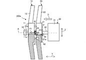
- FIG. 3 is a cross-sectional view of the blower 200a according to Embodiment 1 of the present invention. Based on FIG.2 and FIG.3, the structure of the air blower 200a is demonstrated.
- the two blowers 200a have the same structure.
- the blower 200a includes a first fan 10, a second fan 20, a motor 30, and an elastic body 35.
- the motor 30 includes a motor main body 31 fixed to the attachment member 4 and a motor shaft 32 rotated by the motor main body 31.
- the motor shaft 32 is formed with a columnar region and a sliding region 32ba provided in the front part from the columnar region.
- the sliding region 32a has, for example, a shape in which a part of the outer peripheral surface is cut out by D cut.
- the first fan 10 is attached to the motor shaft 32 and rotates when the power of the motor 30 is transmitted.
- the first fan 10 includes a cylindrical first boss portion 11 and a plurality of first blade portions 12 arranged on the outer side in the radial direction from the outer periphery of the first boss portion 11.
- the first boss portion 11 is formed with a first shaft hole 11a having the same shape as the cross-sectional shape of the sliding region 32a formed in the motor shaft 32, and the sliding region 32a of the motor shaft 32 is formed in the first shaft hole 11a. Inserted.
- a nut 33 is fastened to the front end of the motor shaft 32.
- the nut 33 prevents the first fan 10 from falling off the motor shaft 32.
- the motor 30 is driven, the motor shaft 32 rotates about the rotation axis A, and the first fan 10 attached to the motor shaft 32 rotates.
- the first fan 10 rotates, an air flow is generated from rear to front (in the direction of arrow D).
- the second fan 20 is disposed on the upstream side of the airflow generated by the rotation of the first fan 10 and is rotatably attached to the motor shaft 32 via a bearing 36.
- the second fan 20 includes a cylindrical second boss portion 21 and a plurality of second blade portions 22 arranged on the outer side in the radial direction from the outer periphery of the second boss portion 21.
- a second shaft hole 21 a having a circular cross section is formed in the second boss portion 21, and an outer ring of the bearing 36 is fixed to the second shaft hole 21 a.
- the inner ring of the bearing 36 is fixed to the second shaft hole 21a. That is, the second fan 20 does not rotate in synchronization with the motor shaft 32 by the bearing 36 even if the motor shaft 32 rotates.
- the motor shaft 32 is supported so as to be able to rotate about the rotation axis A.
- a movement restricting portion 34 is fixed to the motor shaft 32 on the rear side of the second fan 20.
- the movement restricting portion 34 has, for example, an outer diameter larger than that of the second shaft hole 21a and is formed in a ring shape in which the motor shaft 32 is passed through the center.
- the movement restricting unit 34 restricts the movement of the second fan 20 to the rear side.
- the motor shaft 32 may be press-fitted into the second shaft hole 21a of the second boss portion 21 without providing the movement restricting portion 34.
- the elastic body 35 is disposed between the first fan 10 and the second fan 20 and urges the first fan to the downstream side of the airflow.
- the elastic body 35 is formed of a spiral spring such as a compression spring, for example, and is wound around the motor shaft 32.
- the rear end of the elastic body 35 is connected to the second boss portion 21, and the front end of the elastic body 35 biases the first boss portion 11 to the downstream side.
- hub part 11 is arrange
- the second boss portion 21 is disposed between the elastic body 35 and the movement restricting portion 34, and the rear position is fixed by the movement restricting portion 34.
- the blower 200a has a fan connecting portion 40 that connects the first fan 10 and the second fan 20 together.
- the fan connecting portion 40 includes a first connecting portion 41 provided on the first boss portion 11 and a second connecting portion 42 provided on the second boss portion 21.
- the second connecting portion 42 is provided at the same position in the radial direction so as to face the first connecting portion 41.
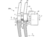
- FIG. 4 is a cross-sectional view showing a connection state between the first fan 10 and the second fan 20 of the blower 200a of FIG.
- the 1st connection part 41 has the shape which protruded to the 2nd fan 20 side, and the 2nd connection part 42 is formed in the concave shape in which the 1st connection part 41 is inserted.
- the first connecting portion 41 has a columnar shape, and the second connecting portion is formed in a cylindrical shape.
- the shape of the 1st connection part 41 and the shape of the 2nd fan 20 are not limited to column shape and cylindrical shape, What kind of shape may be sufficient if it is a shape to fit.
- the 1st connection part provided in the 1st fan 10 may have a concave shape
- the 2nd connection part provided in the 2nd fan 20 may have a protruding shape.
- the first boss portion 11 receives an elastic force F1 from the elastic body 35 toward the nut 33 side.
- the position of the rear end of the elastic body 35 is fixed by the second boss portion 21, when the magnitude of the negative pressure F changes according to the number of rotations of the first fan 10, the length of the elastic body 35 to shrink changes.
- the position of the front end of the elastic body 35 is also displaced along the axial direction (arrow Y direction). Therefore, the first fan 10 approaches the second fan 20 as the rotational speed of the first fan 10 increases.
- the air volume can be adjusted by the length of the elastic body 35 and the length of the first connecting portion 41.
- the rotation speed of the first fan 10 when the first fan 10 and the second fan 20 are connected is the connection rotation speed Fa.
- connection rotation speed Fa When the rotation speed of the first fan 10 reaches the connection rotation speed Fa, the first fan 10 moves to the second fan 20 side, and the first connection portion 41 and the second connection portion 42 are fitted together, so that the first fan 10 and the second fan 20 are connected. At this time, the rotational power of the first fan 10 is transmitted to the second fan 20 via the fan connecting portion 40, and the first fan 10 and the second fan 20 are rotated by the power of the motor 30.
- the blower 200a supplies outside air to the heat exchanger 2 with a large air volume.
- connection when the rotation speed of the motor 30 decreases and the rotation speed of the first fan 10 becomes less than the connection rotation speed Fa, the negative pressure F2 decreases. Pushed back. Thereby, connection with the 1st fan 10 and the 2nd fan 20 is canceled, and the 2nd fan 20 stops.
- the blower 200a switching between the operation of one fan by the first fan 10 and the operation of two fans by the first fan 10 and the second fan 20 is performed according to the rotation speed of the first fan 10. Be controlled. Therefore, the blower 200a can output a wide range of air volumes from a small air volume to a large air volume according to the number of rotations of the motor 30 controlled by the control device 3.
- the length and the spring constant of the elastic body 35 are preferably set in advance so that the operation is switched when the rotational speed of the first fan 10 reaches a desired rotational speed.
- the 1st connection part 41 and the 2nd connection part 42 do not need to fit.
- the first connecting part 41 and the second connecting part 42 may be rubber or the like attached to the first fan 10 and the second fan 20, respectively.
- the rotation speed of the first fan 10 rises and approaches the connection rotation speed Fa
- the separated first connection portion 41 and second connection portion 42 come into contact with each other.
- the rotation speed of the first fan 10 reaches the connection rotation speed Fa
- the frictional force acting between the surface of the first connection portion 41 and the surface of the second connection portion 42 increases, and the first fan 10 and the first fan 10 The two fans 20 rotate together.
- the blower 200a of the first embodiment urges the second fan 20 disposed on the upstream side of the airflow generated by the rotation of the first fan 10 and the first fan 10 toward the downstream side of the airflow.
- An elastic body 35 is provided.
- the negative pressure F2 formed on the upstream side of the first fan 10 becomes larger than the elastic force F1 of the elastic body 35, and the first fan 10 moves toward the second fan 20 side. Slide.
- the power of the first fan 10 is transmitted to the second fan 20 by the fan connecting portion 40.
- the magnitude of the negative pressure F2 is determined according to the rotational speed of the motor. Therefore, since the first fan 10 and the second fan 20 are connected and disconnected according to the number of rotations of the motor 30, the blower 200a controls switching of the number of rotating fans without depending on the ambient temperature. can do.
- the first connecting portion 41 has a shape protruding toward the second fan 20 side, and the second connecting portion 42 is formed in a concave shape into which the first connecting portion 41 is inserted. Accordingly, when the first fan 10 rotates and slides toward the second fan 20, the first connecting portion 41 is inserted into the second connecting portion 42, and the first fan 10 and the second fan 20 are connected. Thus, with a simple structure, the operation of one fan and the simultaneous operation of two fans can be reliably switched.
- FIG. FIG. 5 is a cross-sectional view of a blower according to Embodiment 2 of the present invention.
- the shape of the first connecting portion 141 is different from that in the first embodiment.
- the same components as those in the first embodiment are denoted by the same reference numerals and description thereof is omitted.
- the first connecting portion 141 has a tapered shape and extends from the first boss portion 11 to the second boss portion 21.
- the 1st connection part 141 has a column shape, and the taper part 141a is formed in the outer periphery of the front-end
- the first connecting portion 141 has a tapered shape.
- the taper part 141a functions as a guide, and the first fan 10 and the second fan 20 can be connected more smoothly than in the case of the first embodiment.
- FIG. FIG. 6 is a cross-sectional view of a blower 200a according to Embodiment 3 of the present invention.
- the shape of the first connecting portion 141 is different from that in the second embodiment.
- the same components as those in the second embodiment are denoted by the same reference numerals and description thereof is omitted.
- the second connecting portion 142 is provided on the surface of the second boss portion 21 facing the first boss portion 11 and accommodates the first connecting portion 141.
- the 2nd connection part 142 has the shape dented in the shape cylinder shape, for example.
- the opening diameter of the edge part 142a of the 2nd connection part 142 is formed larger than the inside by taper or chamfering.
- the second connecting portion 142 has an opening diameter of the edge portion 142a larger than the inside. Therefore, even when the 1st fan 10 rotates and the 2nd fan 20 has stopped, interference with the edge 142a of the 1st connection part 141 and the 2nd connection part 142 is suppressed, and the 2nd connection part 142 is detected.
- the entrance can be widened. Therefore, the first connecting portion 141 can easily enter the second connecting portion 142 when the first fan 10 and the second fan 20 are connected.
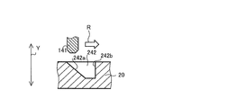
- FIG. 7 is a front view showing the configuration around the second boss portion according to Embodiment 4 of the present invention. 8 is a cross-sectional view showing a BB cross section of FIG.
- the configuration of the fan connecting portion 40 according to the fourth embodiment will be described with reference to FIGS.
- the fourth embodiment is different from the second embodiment in that the second connecting portion 242 is a long hole.
- the same components as those in the second embodiment are denoted by the same reference numerals, and description thereof is omitted.
- the 2nd connection part 242 has the shape extended in a rotation direction (arrow R direction).
- the second connecting portion 242 is provided on the surface of the second boss portion 21 that faces the first boss portion 11 and is formed in an arc shape with the rotation axis A as the center.
- the first fan 10 is provided with three first connecting portions 141
- the second fan 20 is provided with three second connecting portions 242 into which the first connecting portions 141 are inserted.
- Each second connecting portion 242 has an inclined portion 242a on the upstream side in the rotation direction (arrow R direction).
- the inclined portion 242a is formed such that the depth of the elongated hole gradually becomes deeper as it goes downstream in the rotational direction.
- the inclination angle of the inclined portion 242a may be the same as the inclination angle of the tapered portion 141a formed in the first connecting portion 141.
- the first connection portion 141 When the motor 30 is driven and the rotation speed of the first fan 10 is equal to or higher than the connection rotation speed Fa, the first connection portion 141 is caused by the tapered portion 141a of the first connection portion 141 and the inclined portion 242a of the second connection portion 242. It is guided into the second connecting part 242. Specifically, since the first fan 10 rotates and is urged toward the second fan 20, when the first connecting portion 141 reaches the second connecting portion 242 on the track, first, the tapered portion 141 a. Is guided by the inclined portion 242a and inserted into the second connecting portion 142.
- the first connecting portion 141 moves in the rotation direction (arrow R direction) as the first fan 10 rotates, hits the inner side surface 242b on the downstream side of the second connecting portion 242, and pushes in the rotating direction. Thereby, the rotational power of the first fan 10 is transmitted to the second fan 20. Further, when the rotation speed of the first fan 10 becomes smaller than the connection rotation speed Fa and the connection between the first fan 10 and the second fan 20 is released, the inclined portion 242a and the taper portion 141a cause the first connection. The part 141 is guided out of the second connecting part 242.
- the second connecting portion 242 has a shape extending in the rotation direction (arrow R direction). Accordingly, the second connecting portion 242 can be disposed longer on the track of the first connecting portion 141, so that the first connecting portion 141 that moves with the rotation of the first fan 10 can be used. It is possible to easily enter the stopped second connecting portion 142.
- the depth of the second connecting portion 242 increases from the upstream to the downstream in the rotation direction (arrow R direction).
- the inclination part 242a which functions as a guide can be provided in the position where the 1st connection part 141 comes in and out. Therefore, it is possible to suppress interference between the first connecting portion 141 and the second connecting portion at the time of connection and release of connection with a simple structure. As a result, it is possible to switch between the operation of one fan and the two fans while stabilizing the rotation of the first fan 10 and the second fan 20.
- FIG. FIG. 9 is a perspective view showing a state of being attached to a heat exchanger of a blower according to Embodiment 5 of the present invention.
- the first fan 310 and the second fan 320 have different fan diameters.
- the same components as those in the first embodiment are denoted by the same reference numerals and description thereof is omitted.
- the first fan 310 is smaller than the case of the first embodiment, and the second fan 320 is larger than the case of the first embodiment. That is, the blower 200 b is configured such that the first fan 310 is smaller than the second fan 320.
- the diameter S1 including the first blade portion 312 of the first fan 310 and the diameter S2 including the second blade portion 322 of the second fan 320 are the maximum airflow when the blower 200b operates two fans. Is set in advance so as to be the same level as in the first embodiment.
- the motor 30 When the motor 30 is driven at a low speed and the rotation speed of the first fan 310 is smaller than the connection rotation speed Fa, the first fan 310 and the second fan 320 are in a separated state. At this time, the second fan 320 is stopped, and the blower 200b supplies outside air to the heat exchanger 2 with a small air volume.
- the air volume of the blower 200b is the same as that of the first embodiment. It becomes smaller than the air volume of the blower 200a.
- the first fan 310 and the second fan 320 are connected via the fan connection portion 40 and integrated. Rotate.
- the blower 200b supplies outside air to the heat exchanger 2 with a large air volume.
- the blower 200b since the diameter S2 of the second fan 320 is larger than that in the first embodiment, when the rotational speed of the motor 30 is driven at the upper limit value, the blower 200b is operated by operating the two fans. The same maximum air volume as in the first embodiment can be output.
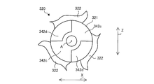
- FIG. 10 is a front view showing an example of the configuration around the second boss portion according to Embodiment 5 of the present invention.
- the load applied to the fan connecting portion 40 at the time of connection. Becomes larger.
- the fan connecting portion 40 may be formed larger than the case of the first embodiment so that the load applied to the fan connecting portion 40 is distributed.
- the second connecting portion includes second concave portions 342 d and second convex portions 342 c that are alternately provided in the second boss portion 321 along the rotation direction (arrow R direction). .
- the second connecting portion is provided on the surface of the second boss portion 321 that faces the first boss portion 311.
- the first connecting portion has first concave portions and first convex portions provided alternately on the first boss portion 311 along the rotation direction (arrow R direction).
- the first connecting portion is provided on the surface of the first boss portion 311 that faces the second boss portion 321.
- the first connecting portion and the second connecting portion are such that when the first fan 10 slides toward the second fan 20, the first convex portion and the second concave portion are engaged, and the first concave portion and the second convex portion are Are connected by meshing.
- the first connecting portion and the second connecting portion mesh with each other in the rotation direction of the motor 30 (the direction of the arrow R), thereby ensuring a contact area between the first connecting portion and the second connecting portion, and the fan connecting portion. Can be dispersed, and the durability of the blower 200b can be improved.
- the diameter S1 of the first fan 310 is smaller than the diameter S2 of the second fan 320.
- the first fan 310 having a smaller diameter than the second fan 320 rotates and the second fan 320 stops, so that the air volume is reduced compared to the case of the first embodiment.
- Embodiment 1 Although the two air blowers 200a are arrange
- the air blower 200a may be used for a fan.
- the lower limit air volume can be made smaller than before, and the user's comfort can be improved.
- a compression spring is used as the elastic body 35
- a tension spring may be used as the elastic body 35 and the first fan 10 may be pulled from the nut 33 side.
- the first connecting portion 41 is illustrated as the same member as the first fan 10, but the first connecting portion 41 may be made of a different material from the first fan 10.
- a metal pin may be installed in the first fan 10 as the first connecting portion 41 by outsert molding.
- the case where the first fan 10 and the second fan 20 have the same diameter has been described based on the configuration of the first embodiment.
- the first fan of the second, third, and fourth embodiments. 10 and the second fan 20 may have the same diameter.
- blower 200a includes two fans
- it may be configured by three or more.
Landscapes
- Engineering & Computer Science (AREA)
- Mechanical Engineering (AREA)
- General Engineering & Computer Science (AREA)
- Chemical & Material Sciences (AREA)
- Combustion & Propulsion (AREA)
- Structures Of Non-Positive Displacement Pumps (AREA)
- Other Air-Conditioning Systems (AREA)
Abstract
送風機及び室外機は、モータシャフトを有するモータと、モータシャフトに軸方向へ摺動するように取り付けられ、モータの動力により回転して気流を発生させる第1ファンと、第1ファンの回転により発生する気流の上流側に配置され、モータシャフトに回転自在に取り付けられた第2ファンと、第1ファンを気流の下流側へ付勢する弾性体と、第1ファンに設けられた第1連結部と、第2ファンに設けられた第2連結部とを有し、第1ファンが第2ファン側へ摺動したとき、第1連結部と第2連結部とが連結するファン連結部とを備えている。
Description
本発明は、複数のファンを備えた送風機及び室外機に関する。
従来、送風機は、例えば空気調和装置の室外機に搭載され、室外熱交換器に外気を供給するのに利用される。ファンの回転数は、必要とされる風量が供給されるように調整される。回転数による風量の制御の他に、1つのモータに2つのファンを設け、ファン1台の駆動と、ファン2台の同時駆動とを切り替える送風機が知られている(例えば、特許文献1参照)。特許文献1の送風機において、感熱クラッチにより、2つのファンが連結され、ファン1台の駆動とファン2台の同時駆動とが切り替えられる。
しかしながら、特許文献1の送風機において、感熱クラッチは周辺温度に応じて動作するため、回転するファンの数の切り替えが周囲温度に依存し、切り替えのタイミングを制御できない場合がある。
本発明は、上記のような課題を解決するためになされたもので、周囲温度に依存せず、回転するファンの数の切り替えを制御することができる送風機及び室外機を提供することを目的とする。
本発明に係る送風機は、モータシャフトを有するモータと、前記モータシャフトに軸方向へ摺動するように取り付けられ、前記モータの動力により回転して気流を発生させる第1ファンと、前記第1ファンの回転により発生する気流の上流側に配置され、前記モータシャフトに回転自在に取り付けられた第2ファンと、前記第1ファンを前記気流の下流側へ付勢する弾性体と、前記第1ファンに設けられた第1連結部と、前記第2ファンに設けられた第2連結部とを有し、前記第1ファンが前記第2ファン側へ摺動したとき、前記第1連結部と前記第2連結部とが連結するファン連結部とを備えている。
本発明の送風機及び室外機によれば、第2ファンは気流の上流側に配置され、弾性体は第1ファンを気流の下流側へ付勢するので、モータの回転数が大きくなると、第1ファンの上流側に形成される負圧が弾性体の弾性力よりも大きくなる。そのため、第1ファンが第2ファン側へ摺動し、第1連結部と第2連結部とが連結する。負圧の大きさはモータの回転数に応じて決まるため、モータ回転数に応じて2つのファンの連結及び連結解除が行われ、周囲温度に依存せず、回転するファンの数の切り替えを制御することができる。
実施の形態1.
図1は、本発明の実施の形態1に係る室外機の構成である。室外機100は、例えば空気調和装置の室外機であり、接続配管により室内機に接続されて冷凍サイクル装置を形成する。図1の矢印X方向は室外機100の幅方向を表し、矢印Y方向は室外機100の奥行き方向を表し、矢印Z方向は室外機100の高さ方向を表している。
図1は、本発明の実施の形態1に係る室外機の構成である。室外機100は、例えば空気調和装置の室外機であり、接続配管により室内機に接続されて冷凍サイクル装置を形成する。図1の矢印X方向は室外機100の幅方向を表し、矢印Y方向は室外機100の奥行き方向を表し、矢印Z方向は室外機100の高さ方向を表している。
室外機100は、筐体100aに、圧縮機1と、熱交換器2とを収容した構造を有する。また室外機100は、制御装置3と、熱交換器2に送風する送風機200aとを有する。制御装置3は、圧縮機1の回転数及び送風機200aの回転数を制御する。
図2は、本発明の実施の形態1に係る送風機200aの熱交換器2に取り付けられた状態を示す斜視図である。取付部材4は筐体100aに固定されており、取付部材4を介して、熱交換器2に2つの送風機200aが上下方向(矢印Z方向)に並んで取り付けられている。取付部材4は、例えば上下方向(矢印Z方向)に延びる2本のレール状の部材から成り、ネジ等の固定部材により固定された送風機200aを支持する。
図3は、本発明の実施の形態1に係る送風機200aの断面図である。図2及び図3に基づき、送風機200aの構成について説明する。なお、2つの送風機200aは同一の構造を有している。送風機200aは、第1ファン10と、第2ファン20と、モータ30と、弾性体35とを備える。モータ30は、取付部材4に固定されたモータ本体31と、モータ本体31により回転されるモータシャフト32とを有している。モータシャフト32には、円柱状に形成された領域と、円柱状の領域から前方部に設けられた摺動領域32baが形成されている。摺動領域32aは、例えば、Dカットにより外周面の一部が切り欠かれた形状を有する。
第1ファン10は、モータシャフト32に取り付けられ、モータ30の動力が伝達されることで回転する。第1ファン10は、筒状の第1ボス部11と、第1ボス部11の外周から半径方向の外側に配置された複数の第1羽根部12とを有する。第1ボス部11には、モータシャフト32に形成された摺動領域32aの断面形状と同形状の第1軸孔11aが形成され、第1軸孔11aにモータシャフト32の摺動領域32aが挿入される。
モータシャフト32の前方の端部には、ナット33が締結されている。ナット33は、第1ファン10がモータシャフト32から脱落するのを防止する。モータ30が駆動するとき、モータシャフト32が回転軸Aを軸として回転し、モータシャフト32に取り付けられた第1ファン10が回転する。第1ファン10が回転すると、後方から前方へ(矢印D方向へ)気流が生じる。
第2ファン20は、第1ファン10の回転により発生する気流の上流側に配置され、軸受36を介してモータシャフト32に回転自在に取り付けられている。第2ファン20は、筒状の第2ボス部21と、第2ボス部21の外周から半径方向の外側に配置された複数の第2羽根部22とを有する。第2ボス部21には、断面円形状の第2軸孔21aが形成されており、第2軸孔21aに、軸受36の外輪が固定されている。軸受36の内輪は、第2軸孔21aに固定されている。すなわち、第2ファン20は、モータシャフト32が回転しても軸受36により、モータシャフト32と同期して回転しない。モータシャフト32が回転軸Aを軸として回転できるように支持している。第1ファン10及び第2ファン20の2台が駆動しているとき、第1ファン10が1台で運転しているときに比べ、大風量の気流が生じる。
第2ファン20の後方側には、移動規制部34がモータシャフト32に固定されている。移動規制部34は、例えば、第2軸孔21aよりも外径が大きく、中央にモータシャフト32が通されたリング状に形成されている。移動規制部34は、第2ファン20の後方側への移動を規制する。なお、移動規制部34を設けず、第2ボス部21の第2軸孔21aにモータシャフト32が圧入されていてもよい。
弾性体35は、弾性体35は、第1ファン10と第2ファン20との間に配置され、第1ファンを気流の下流側へ付勢する。弾性体35は、例えば圧縮スプリング等の螺旋状のバネで形成されており、モータシャフト32に巻き付けられている。弾性体35の後方端は第2ボス部21に接続され、弾性体35の前方端は第1ボス部11を下流側へ付勢する。このように、第1ボス部11は、ナット33と弾性体35との間に配置され、前方位置がナット33により規定され、モータシャフト32の摺動領域32aを移動する。第2ボス部21は、弾性体35と移動規制部34との間に配置され、後方位置が移動規制部34により固定されている。
また送風機200aは、第1ファン10と第2ファン20とを連結するファン連結部40を有する。ファン連結部40は、第1ボス部11に設けられた第1連結部41と、第2ボス部21に設けられた第2連結部42とを有している。第2連結部42は、第1連結部41と対向するように径方向における同一の位置に設けられている。第1ファン10が第2ファン20側へ軸方向(矢印Y方向)に摺動したとき、第1連結部41と第2連結部52とが連結する。これにより、モータ30によって回転する第1ファン10の動力が、第2ファン20へ伝達される。
図4は、図3の送風機200aの第1ファン10と第2ファン20との連結状態を示す断面図である。例えば、第1連結部41は、第2ファン20側へ突出した形状を有し、第2連結部42は、第1連結部41が挿入される凹状に形成されている。具体的には、第1連結部41は円柱形状を有しており、第2連結部は円筒状に形成されている。第1ファン10の回転により第1連結部41が第2連結部42へ摺動した場合に、第1連結部41が第2連結部42に嵌まることにより、第1ファン10と第2ファン20とが連結される。
なお、第1連結部41の形状及び第2ファン20の形状は、円柱形状及び円筒状に限定されず、嵌合する形状であればどのような形状であってもよい。例えば、第1ファン10に設けられた第1連結部が凹形状を有し、第2ファン20に設けられた第2連結部が突形状を有するものあってもよい。
次に、図3及び図4に基づき、弾性体35及び第1ボス部11にそれぞれ作用する力について説明する。モータ30の駆動により第1ファン10が回転すると、矢印D方向に気流が生じることにより、第1羽根部12の気流上流側に生じた負圧F2が、第1ファン10全体にかかる。一方、弾性体35から弾性力F1がかかる。第1ファン10は、負圧F2が弾性体35の弾性力F1より大きくなると、第2ファン20側へ移動する。負圧F2の大きさは、第1ファン10の回転数によって決まり、弾性力F1の大きさは、弾性体35の特性によって決まる。つまり、モータ30の回転数が大きくなり、第1ファン10の回転数が大きくなるほど、負圧F2は大きくなる。
一方、第1ボス部11は、弾性体35から、ナット33側へ向く弾性力F1を受ける。負圧F2が大きいほど弾性体35は多く縮み、第1ボス部11が受ける弾性力F1の大きさも、弾性体35の縮んだ長さに比例して大きくなる。弾性体35の後方端は第2ボス部21により位置が固定されているため、第1ファン10の回転数に応じて負圧Fの大きさが変化すると、弾性体35の縮む長さが変わり、弾性体35の前方端の位置も、軸方向(矢印Y方向)に沿って変位する。したがって、第1ファン10の回転数が大きくなるほど、第1ファン10が第2ファン20へ近づく。
そして、第1ファン10は、第1連結部41の先端と第2連結部42の開口との長さ分だけ軸方向に移動すると、第2ファン20に連結する。よって、弾性体35の長さ及び第1連結部41の長さによって風量の調整が可能である。
次に、図1~図4に基づき、送風機200aの動作について説明する。以下、第1ファン10と第2ファン20とが連結するときの第1ファン10の回転数が連結回転数Faであるものと定義して説明する。
モータ30が停止しているとき、第1ファン10は停止しており、第1ファン10から弾性体35へ、負圧F2も生じていない。このため、図3に示されるように第1ファン10と第2ファン20とは離間しており、第2ファン20も停止している。
モータ30が低速で駆動し、連結回転数Faよりも小さい回転数で第1ファン10が回転しているとき、第1ボス部11がモータシャフト32に沿って気流上流側へ摺動し、第2ボス部21へ近づく。そして、負圧F2と弾性力F1とが釣り合う位置で、第1ボス部11の摺動が止まる。このとき、第1ファン10と第2ファン20とは離間している。そのため、第2ファン20は停止しており、送風機200aは、小風量で熱交換器2に外気を供給する。
第1ファン10の回転数が連結回転数Faになると、第1ファン10は第2ファン20側へ移動し、第1連結部41と第2連結部42とが嵌合して、第1ファン10と第2ファン20とが連結する。このとき、ファン連結部40を介して第1ファン10の回転の動力が第2ファン20へ伝達され、モータ30の動力により、第1ファン10と第2ファン20とが回転する。
連結後、第1ファン10の回転数がさらに大きくなると、負圧F2が弾性力F1を超過する。このとき、負圧F2が弾性力F1との差により、第1ボス部11は第2ボス部21側へ移動しようとするため、第1ファン10と第2ファン20とは連結状態が維持される。第1ファン10と第2ファン20とが連結されているとき、送風機200aは、大風量で熱交換器2に外気を供給する。
一方、連結後、モータ30の回転数が低下し、第1ファン10の回転数が連結回転数Fa未満になると、負圧F2が低下するため、第1ファン10は弾性体35によってナット33側へ押し戻される。これにより、第1ファン10と第2ファン20との連結が解除され、第2ファン20は停止する。
このように、送風機200aにおいて、第1ファン10によるファン1台の運転と、第1ファン10及び第2ファン20によるファン2台の運転との切り替えが、第1ファン10の回転数に応じて制御される。したがって、送風機200aは、制御装置3により制御されるモータ30の回転数に応じて、小風量から大風量の広範囲の風量を出力することができる。ここで、弾性体35の長さ及びバネ定数は、第1ファン10の回転数が所望の回転数となったときに運転が切り替わるよう、予め設定されているとよい。
なお、第1連結部41と第2連結部42とは、嵌合するものでなくてもよい。例えば、第1連結部41及び第2連結部42は、第1ファン10及び第2ファン20にそれぞれ貼付されたゴム等であってもよい。この場合、第1ファン10の回転数が上昇して連結回転数Faに近づくと、離れていた第1連結部41と第2連結部42とが接触する。そして、第1ファン10の回転数が連結回転数Faになると、第1連結部41の表面と第2連結部42の表面との間に作用する摩擦力が大きくなり、第1ファン10と第2ファン20とが一体となって回転する。
以上のように、実施の形態1の送風機200aは、第1ファン10の回転により発生する気流の上流側に配置された第2ファン20と、第1ファン10を気流の下流側へ付勢する弾性体35を備える。これにより、モータ30の回転数が大きくなると、第1ファン10の上流側に形成される負圧F2が弾性体35の弾性力F1よりも大きくなり、第1ファン10が第2ファン20側へ摺動する。そして、ファン連結部40により第1ファン10の動力が第2ファン20へ伝達される。ここで、負圧F2の大きさはモータの回転数に応じて決まる。したがって、モータ30の回転数に応じて第1ファン10と第2ファン20との連結及び連結解除が行われるので、送風機200aは、周辺温度に依存せず、回転するファンの数の切り替えを制御することができる。
また第1連結部41は、第2ファン20側へ突出した形状を有し、第2連結部42は、第1連結部41が挿入される凹状に形成されている。これにより、第1ファン10が回転し、第2ファン20側へ摺動すると、第2連結部42に第1連結部41が挿入され、第1ファン10と第2ファン20とが連結する。このように、単純な構造で、ファン1台の運転とファン2台の同時運転とを確実に切り替えることができる。
実施の形態2.
図5は、本発明の実施の形態2に係る送風機の断面図である。実施の形態2において、第1連結部141の形状が、実施の形態1の場合とは異なる。以下、実施の形態2において、実施の形態1の場合と同一の構成については同一符号を付して説明を省略する。
図5は、本発明の実施の形態2に係る送風機の断面図である。実施の形態2において、第1連結部141の形状が、実施の形態1の場合とは異なる。以下、実施の形態2において、実施の形態1の場合と同一の構成については同一符号を付して説明を省略する。
第1連結部141は、先細り形状を有し、第1ボス部11から第2ボス部21へ延びている。具体的には、第1連結部141は円柱形状を有しており、先端の外周に、テーパ部141aが形成されている。モータ30が駆動し、第1ファン10の回転数が連結回転数Faになると、テーパ部141aによって第1連結部141が第2連結部42内へ誘導される。
以上のように、実施の形態2では、第1連結部141は先細り形状を有している。これにより、テーパ部141aがガイドとして機能し、実施の形態1の場合よりも滑らかに第1ファン10と第2ファン20とを連結することができる。
実施の形態3.
図6は、本発明の実施の形態3に係る送風機200aの断面図である。実施の形態3において、第1連結部141の形状が、実施の形態2の場合とは異なる。以下、実施の形態3において、実施の形態2の場合と同一の構成については同一符号を付して説明を省略する。
図6は、本発明の実施の形態3に係る送風機200aの断面図である。実施の形態3において、第1連結部141の形状が、実施の形態2の場合とは異なる。以下、実施の形態3において、実施の形態2の場合と同一の構成については同一符号を付して説明を省略する。
第2連結部142は、第2ボス部21の第1ボス部11と対向する面に設けられ、第1連結部141を収容する。第2連結部142は、例えば形円筒状に凹んだ形状を有している。第2連結部142の縁部142aの開口径は、テーパ又は面取りにより、内部よりも大きく形成されている。モータ30が駆動し、第1ファン10の回転数が連結回転数Faになると、第1連結部141のテーパ部141aと第2連結部142の縁部142aとにより、第1連結部141が第2連結部142内へ誘導される。
以上のように、実施の形態3では、第2連結部142は、内部より縁部142aの開口径が大きいものである。これにより、第1ファン10が回転し、第2ファン20が停止している場合でも、第1連結部141と第2連結部142の縁部142aとの干渉を抑制し、第2連結部142の入口を広くすることができる。したがって、第1ファン10と第2ファン20との連結時に、第1連結部141を第2連結部142へ入り易くすることができる。
実施の形態4.
図7は、本発明の実施の形態4に係る第2ボス部周辺の構成を示す正面図である。図8は、図7のB-B断面を示す断面図である。図7及び図8を用いて実施の形態4のファン連結部40の構成を説明する。実施の形態4において、第2連結部242が長穴である点が、実施の形態2の場合とは異なる。以下、実施の形態2の場合と同一の構成については同一符号を付して説明を省略する。
図7は、本発明の実施の形態4に係る第2ボス部周辺の構成を示す正面図である。図8は、図7のB-B断面を示す断面図である。図7及び図8を用いて実施の形態4のファン連結部40の構成を説明する。実施の形態4において、第2連結部242が長穴である点が、実施の形態2の場合とは異なる。以下、実施の形態2の場合と同一の構成については同一符号を付して説明を省略する。
第2連結部242は、回転方向(矢印R方向)に延びる形状を有している。第2連結部242は、第2ボス部21の第1ボス部11と対向する面に設けられ、回転軸Aを中心とする円弧状に形成されている。第1ファン10には、3つの第1連結部141が設けられており、第2ファン20には、各第1連結部141が挿入される3つの第2連結部242が設けられている。
各第2連結部242は、回転方向(矢印R方向)の上流側に傾斜部242a有している。傾斜部242aは、回転方向の下流側へ進むにつれ長穴の深さが次第に深くなるように形成されている。傾斜部242aの傾斜角は、第1連結部141に形成されたテーパ部141aの傾斜角と同じであるとよい。
モータ30が駆動し、第1ファン10の回転数が連結回転数Fa以上になると、第1連結部141のテーパ部141aと第2連結部242の傾斜部242aとにより、第1連結部141が第2連結部242内へと誘導される。具体的には、第1ファン10は回転するとともに第2ファン20側へ付勢されているので、第1連結部141が、軌道上の第2連結部242に到達すると、まず、テーパ部141aが傾斜部242aにより誘導され第2連結部142内へ挿入される。そして第1連結部141は、第1ファン10の回転に伴って回転方向(矢印R方向)へ移動し、第2連結部242の下流側の内側面242bに当たり、回転方向へ押す。これにより、第1ファン10の回転の動力が第2ファン20へ伝達される。また、第1ファン10の回転数が連結回転数Faよりも小さくなり、第1ファン10と第2ファン20との連結が解除される際、傾斜部242aとテーパ部141aとにより、第1連結部141が第2連結部242の外へ導かれる。
以上のように、実施の形態4では、第2連結部242は、回転方向(矢印R方向)に延びる形状を有する。第2連結部242は、これにより、第1連結部141の軌道上に第2連結部242を長く配置することができるので、第1ファン10の回転にともなって移動する第1連結部141を、停止した第2連結部142へ入り易くすることができる。
また第2連結部242は、回転方向(矢印R方向)の上流から下流へ向かって深さが深くなる。これにより、第2連結部242において、第1連結部141が出入りする位置に、ガイドとして機能する傾斜部242aを設けることができる。したがって、簡単な構造で、連結時及び連結解除時における第1連結部141と第2連結部との干渉を抑制することができる。その結果、第1ファン10及び第2ファン20の回転を安定させつつ、ファント1台の運転とファン2台を切り替えることができる。
実施の形態5.
図9は、本発明の実施の形態5に係る送風機の熱交換器に取り付けられた状態を示す斜視図である。実施の形態5において、第1ファン310と第2ファン320とは、ファン径が異なっている。以下、実施の形態5において、実施の形態1の場合と同一の構成については同一符号を付して説明を省略する。
図9は、本発明の実施の形態5に係る送風機の熱交換器に取り付けられた状態を示す斜視図である。実施の形態5において、第1ファン310と第2ファン320とは、ファン径が異なっている。以下、実施の形態5において、実施の形態1の場合と同一の構成については同一符号を付して説明を省略する。
実施の形態5において、第1ファン310は実施の形態1の場合よりも小さく、第2ファン320は実施の形態1の場合よりも大きい。つまり送風機200bは、第1ファン310が、第2ファン320よりも小さく構成されている。ここで、第1ファン310の第1羽根部312を含めた径S1及び第2ファン320の第2羽根部322を含めた径S2は、送風機200bがファン2台の運転を行うときの最大風量が実施の形態1の場合と同程度となるように、予め設定されている。
モータ30が低速で駆動し、第1ファン310の回転数が連結回転数Faよりも小さいとき、第1ファン310と第2ファン320とは離間した状態である。このとき、第2ファン320は停止しており、送風機200bは、小風量で熱交換器2に外気を供給する。上述したように、第1ファン310の径S1は実施の形態1の場合に比べて小さいので、モータ30の回転数が下限値に設定されているとき、送風機200bの風量は、実施の形態1の送風機200aの風量よりも小さくなる。
一方、モータ30が高速で駆動し、第1ファン310の回転数が連結回転数Fa以上になると、ファン連結部40を介して第1ファン310と第2ファン320とが連結され、一体となって回転する。このとき、送風機200bは、大風量で熱交換器2に外気を供給する。上述したように、第2ファン320の径S2は実施の形態1の場合に比べて大きいので、モータ30の回転数が上限値で駆動しているとき、送風機200bはファン2台の運転により、実施の形態1の場合と同様の最大風量を出力することができる。
図10は、本発明の実施の形態5に係る第2ボス部周辺の構成の一例を示す正面図である。第1ファン310が第2ファン320よりも小さい構成では、実施の形態1のように第1ファン10と第2ファン20とが同一径である構成に比べ、連結時にファン連結部40にかかる負荷が大きくなる。そのため、ファン連結部40は、実施の形態1の場合よりも大きく形成し、ファン連結部40にかかる負荷を分散するように構成するとよい。
例えば、図10に示されるように、第2連結部は、第2ボス部321に回転方向(矢印R方向)に沿って交互に設けられた第2凹部342dと第2凸部342cとを有する。第2連結部は、第2ボス部321の第1ボス部311と対向する面に設けられている。図示していないが、第1連結部は、第1ボス部311に回転方向(矢印R方向)に沿って交互に設けられた第1凹部と第1凸部とを有する。第1連結部は、第1ボス部311の第2ボス部321と対向する面に設けられている。第1連結部と第2連結部とは、第1ファン10が第2ファン20側へ摺動したときに、第1凸部と第2凹部とが噛み合い、第1凹部と第2凸部とが噛み合うことにより連結する。このように、モータ30の回転方向(矢印R方向)に第1連結部と第2連結部とが噛み合う構成により、第1連結部と第2連結部との接触面積を確保し、ファン連結部にかかる負荷を分散させることができ、送風機200bの耐久性を向上させることができる。
以上のように、実施の形態5において、第1ファン310の径S1は、第2ファン320の径S2よりも小さい。これにより、モータシャフト32が低速で回転するときには、第2ファン320よりも径が小さい第1ファン310は回転し、第2ファン320は停止するので、風量を、実施の形態1の場合よりも小さくすることができる。このように、ファン1台の運転とファン2台の運転との切り替えを制御することができ、且つ風量可変の幅が広い送風機200bを提供することができる。
一般に、送風機のモータには最低回転数の制約がある。このため、ファンの回転数も予め設定された回転数以下で稼働できず、必要とされる風量に対して出力が大きくなる場合がある。例えば冷房運転で室外機の熱交換器が凝縮機として機能する場合、外気温度が低いとき等には、送風機の風量が過多状態となると凝縮圧力が低下し、熱交換器の熱交換効率が低下する。また、凝縮圧力が低下した場合、室内機側の電子膨張弁入口の過冷却液が不足するため、室内機から冷媒音が生じる。特に、外気温度が低下する夜間に冷媒音が発生すると、居住者等に不快感を与える場合がある。一方、送風機200bは、出力する風量の幅を広くすることができるので、風量が過多状態になるのを抑制することができる。
なお、本発明の実施の形態は上記実施の形態に限定されず、種々の変更を行うことができる。例えば、実施の形態1では、室外機100に送風機200aが上下に2台配置されているが、熱交換器2が小さい場合には送風機200aは1台であってもよい。
また、送風機200aが室外機100に設けられる場合について説明したが、風量の調整が必要とされる装置であれば、どのような装置に使用されてもよい。例えば、送風機200aは、扇風機に使用されてもよい。この場合、従来よりも下限の風量を小さくでき、利用者の快適性を向上させることができる。
また、弾性体35として圧縮スプリングを用いる場合について例示したが、弾性体35として引張りスプリングを用い、第1ファン10をナット33側から引っ張る構成としてもよい。
さらに、図3では、第1連結部41は、第1ファン10と同一の部材として図示したが、第1連結部41を、第1ファン10とは異種材料で構成してもよい。例えば第1ファン10が樹脂製である場合には、第1連結部41として金属製のピンを、アウトサート成形により第1ファン10に設置してもよい。同様に、第2連結部42を、インサート成形又はアウトサート成形により第2ファン20に設置してもよい。第1連結部41及び第2連結部42を、樹脂ではなく金属同士で構成することで、高い耐久性を得ることができる。
また、実施の形態5では、実施の形態1の構成に基づき、第1ファン10と第2ファン20とを同一径とした場合について説明したが、実施の形態2、3、4の第1ファン10と第2ファン20とを同一径にしてもよい。
また、送風機200aがファンを2台備える場合について説明したが、3つ以上で構成されてもよい。
1 圧縮機、2 熱交換器、3 制御装置、4 取付部材、10、310 第1ファン、11、311 第1ボス部、11a 第1軸孔、12、312 第1羽根部、20、320 第2ファン、21、321 第2ボス部、21a 第2軸孔、22、322 第2羽根部、30 モータ、31 モータ本体、32 モータシャフト、32a 摺動領域、33 ナット、34 移動規制部、35 摺動領域弾性体、36 軸受、40 ファン連結部、41、141 第1連結部、42、142、242、342 第2連結部、100 室外機、141a テーパ部、142a 縁部、200a、200b 送風機、242a 傾斜部、242b 内側面、342c 突領域、342d 凹領域、A 回転軸、F1 弾性力、F2 負圧、Fa 連結回転数、S1、S2 ファン径。
Claims (9)
- モータシャフトを有するモータと、
前記モータシャフトに軸方向へ摺動するように取り付けられ、前記モータの動力により回転して気流を発生させる第1ファンと、
前記第1ファンの回転により発生する気流の上流側に配置され、前記モータシャフトに回転自在に取り付けられた第2ファンと、
前記第1ファンを前記気流の下流側へ付勢する弾性体と、
前記第1ファンに設けられた第1連結部と、前記第2ファンに設けられた第2連結部とを有し、前記第1ファンが前記第2ファン側へ摺動したとき、前記第1連結部と前記第2連結部とが連結するファン連結部と
を備えた送風機。 - 前記第1連結部は、前記第2ファン側へ突出した形状を有し、
前記第2連結部は、前記第1連結部が挿入される凹状に形成されている
請求項1に記載の送風機。 - 前記第1連結部は、先細り形状を有する
請求項2に記載の送風機。 - 前記第2連結部は、内部より縁部の開口径が大きい
請求項2又は3に記載の送風機。 - 前記第2連結部は、回転方向に延びる形状を有する
請求項2~4のいずれか1項に記載の送風機。 - 前記第1ファンは、第1ボス部と、前記第1ボス部の外周に設けられた複数の羽根部とを有し、
前記第2ファンは、第2ボス部と、前記第2ボス部の外周に設けられた複数の羽根部とを有し、
前記第1連結部は、前記第1ボス部に回転方向に沿って交互に設けられた第1凹部と第1凸部とを有し、
前記第2連結部は、前記第2ボス部に回転方向に沿って交互に設けられた第2凹部と第2凸部とを有し、
前記第1連結部と前記第2連結部とは、前記第1ファンが前記第2ファン側へ摺動したときに、前記第1凸部と前記第2凹部とが噛み合い、前記第1凹部と前記第2凸部とが噛み合うことにより連結する
請求項1に記載の送風機。 - 前記第2連結部は、回転方向の上流から下流へ向かって深さが深くなる
請求項2~5のいずれか1項に記載の送風機。 - 前記第1ファンの径は、前記第2ファンの径よりも小さい
請求項1~7のいずれか1項に記載の送風機。 - 冷媒を圧縮する圧縮機と、
空気と冷媒とを熱交換させる熱交換器と、
前記熱交換器に空気を供給する請求項1~8のいずれか1項に記載の送風機と、
を備える室外機。
Priority Applications (2)
| Application Number | Priority Date | Filing Date | Title |
|---|---|---|---|
| JP2019571878A JP6847279B2 (ja) | 2018-02-15 | 2018-02-15 | 送風機、及び室外機 |
| PCT/JP2018/005259 WO2019159282A1 (ja) | 2018-02-15 | 2018-02-15 | 送風機、及び室外機 |
Applications Claiming Priority (1)
| Application Number | Priority Date | Filing Date | Title |
|---|---|---|---|
| PCT/JP2018/005259 WO2019159282A1 (ja) | 2018-02-15 | 2018-02-15 | 送風機、及び室外機 |
Publications (1)
| Publication Number | Publication Date |
|---|---|
| WO2019159282A1 true WO2019159282A1 (ja) | 2019-08-22 |
Family
ID=67618516
Family Applications (1)
| Application Number | Title | Priority Date | Filing Date |
|---|---|---|---|
| PCT/JP2018/005259 Ceased WO2019159282A1 (ja) | 2018-02-15 | 2018-02-15 | 送風機、及び室外機 |
Country Status (2)
| Country | Link |
|---|---|
| JP (1) | JP6847279B2 (ja) |
| WO (1) | WO2019159282A1 (ja) |
Cited By (3)
| Publication number | Priority date | Publication date | Assignee | Title |
|---|---|---|---|---|
| CN111174338A (zh) * | 2020-02-19 | 2020-05-19 | 广东美的制冷设备有限公司 | 空调室外机及空调器 |
| CN114543196A (zh) * | 2022-01-27 | 2022-05-27 | 青岛海尔空调器有限总公司 | 组合风扇、空调室外机 |
| US20240229826A9 (en) * | 2022-10-21 | 2024-07-11 | Coil Master Corporation | Modular fan array |
Citations (3)
| Publication number | Priority date | Publication date | Assignee | Title |
|---|---|---|---|---|
| JPS5842394U (ja) * | 1981-09-14 | 1983-03-22 | カルソニックカンセイ株式会社 | フアン装置 |
| JPS6012621U (ja) * | 1983-07-07 | 1985-01-28 | マツダ株式会社 | 車両用電動送風機 |
| JP2014171740A (ja) * | 2013-03-11 | 2014-09-22 | Koizumi Seiki Corp | ダブルファン式ヘアドライヤー |
Family Cites Families (1)
| Publication number | Priority date | Publication date | Assignee | Title |
|---|---|---|---|---|
| JP2001003748A (ja) * | 1999-06-15 | 2001-01-09 | Kobe Steel Ltd | 建設機械の冷却装置 |
-
2018
- 2018-02-15 WO PCT/JP2018/005259 patent/WO2019159282A1/ja not_active Ceased
- 2018-02-15 JP JP2019571878A patent/JP6847279B2/ja not_active Expired - Fee Related
Patent Citations (3)
| Publication number | Priority date | Publication date | Assignee | Title |
|---|---|---|---|---|
| JPS5842394U (ja) * | 1981-09-14 | 1983-03-22 | カルソニックカンセイ株式会社 | フアン装置 |
| JPS6012621U (ja) * | 1983-07-07 | 1985-01-28 | マツダ株式会社 | 車両用電動送風機 |
| JP2014171740A (ja) * | 2013-03-11 | 2014-09-22 | Koizumi Seiki Corp | ダブルファン式ヘアドライヤー |
Cited By (3)
| Publication number | Priority date | Publication date | Assignee | Title |
|---|---|---|---|---|
| CN111174338A (zh) * | 2020-02-19 | 2020-05-19 | 广东美的制冷设备有限公司 | 空调室外机及空调器 |
| CN114543196A (zh) * | 2022-01-27 | 2022-05-27 | 青岛海尔空调器有限总公司 | 组合风扇、空调室外机 |
| US20240229826A9 (en) * | 2022-10-21 | 2024-07-11 | Coil Master Corporation | Modular fan array |
Also Published As
| Publication number | Publication date |
|---|---|
| JP6847279B2 (ja) | 2021-03-24 |
| JPWO2019159282A1 (ja) | 2020-12-03 |
Similar Documents
| Publication | Publication Date | Title |
|---|---|---|
| KR101155809B1 (ko) | 팬 및 쉬라우드 조립체 | |
| WO2019159282A1 (ja) | 送風機、及び室外機 | |
| KR101724294B1 (ko) | 공기조화기의 실외기 | |
| JP2009236035A (ja) | 遠心圧縮機及び過給機 | |
| US9303646B2 (en) | Cross flow fan and air conditioner | |
| CN113007133A (zh) | 风扇及散热模块、车辆 | |
| CN108980085A (zh) | 气体处理设备 | |
| CN114450489B (zh) | 风扇组装体及空调机 | |
| US2459377A (en) | Variable-speed pulley | |
| EP3118462B1 (en) | Centrifugal compressor and centrifugal facility having same | |
| CN118564493A (zh) | 蜗壳组件、离心风机和空调器 | |
| CN209838736U (zh) | 风扇 | |
| CN211953103U (zh) | 一种无叶空调扇 | |
| JPH0533797A (ja) | 押し込み式軸流フアン | |
| CN206972608U (zh) | 吹风机用叶轮离心连接机构 | |
| KR100638100B1 (ko) | 후향팬 | |
| CN208749626U (zh) | 格栅结构及出风设备 | |
| CN218955034U (zh) | 风管机内机 | |
| CN213300246U (zh) | 空调器室内机 | |
| KR20110012932A (ko) | 워터펌프용 동력전달장치 | |
| CN223331959U (zh) | 热力膨胀阀、制冷系统和配备有该制冷系统的车辆 | |
| CN205533382U (zh) | 离心式压缩机及具有其的空调器 | |
| CN223709779U (zh) | 空调器 | |
| CN223709780U (zh) | 空调器 | |
| CN223840515U (zh) | 空调器 |
Legal Events
| Date | Code | Title | Description |
|---|---|---|---|
| 121 | Ep: the epo has been informed by wipo that ep was designated in this application |
Ref document number: 18906676 Country of ref document: EP Kind code of ref document: A1 |
|
| ENP | Entry into the national phase |
Ref document number: 2019571878 Country of ref document: JP Kind code of ref document: A |
|
| NENP | Non-entry into the national phase |
Ref country code: DE |
|
| 122 | Ep: pct application non-entry in european phase |
Ref document number: 18906676 Country of ref document: EP Kind code of ref document: A1 |