WO2019155752A1 - Condenser - Google Patents
Condenser Download PDFInfo
- Publication number
- WO2019155752A1 WO2019155752A1 PCT/JP2018/045291 JP2018045291W WO2019155752A1 WO 2019155752 A1 WO2019155752 A1 WO 2019155752A1 JP 2018045291 W JP2018045291 W JP 2018045291W WO 2019155752 A1 WO2019155752 A1 WO 2019155752A1
- Authority
- WO
- WIPO (PCT)
- Prior art keywords
- header tank
- modulator
- refrigerant
- condenser
- protrusion
- Prior art date
Links
Images


Classifications
-
- B—PERFORMING OPERATIONS; TRANSPORTING
- B60—VEHICLES IN GENERAL
- B60H—ARRANGEMENTS OF HEATING, COOLING, VENTILATING OR OTHER AIR-TREATING DEVICES SPECIALLY ADAPTED FOR PASSENGER OR GOODS SPACES OF VEHICLES
- B60H1/00—Heating, cooling or ventilating [HVAC] devices
- B60H1/32—Cooling devices
-
- F—MECHANICAL ENGINEERING; LIGHTING; HEATING; WEAPONS; BLASTING
- F25—REFRIGERATION OR COOLING; COMBINED HEATING AND REFRIGERATION SYSTEMS; HEAT PUMP SYSTEMS; MANUFACTURE OR STORAGE OF ICE; LIQUEFACTION SOLIDIFICATION OF GASES
- F25B—REFRIGERATION MACHINES, PLANTS OR SYSTEMS; COMBINED HEATING AND REFRIGERATION SYSTEMS; HEAT PUMP SYSTEMS
- F25B39/00—Evaporators; Condensers
- F25B39/04—Condensers
Definitions
- the present disclosure relates to a condenser that condenses refrigerant by heat exchange with air.
- a refrigeration cycle such as an air conditioner is provided with a condenser that condenses the refrigerant.
- a condenser that condenses the refrigerant.
- heat exchange is performed between a high-temperature gas-phase refrigerant flowing inside and air flowing outside, and the gas-phase refrigerant condenses into a liquid-phase refrigerant.
- Such a condenser is often provided with a modulator which is a container for separating the gas-liquid refrigerant.
- the modulator is also referred to as a “liquid receiver” and supplies only the liquid-phase refrigerant after gas-liquid separation to the downstream side.
- a subcool section can be cited.
- the modulator is provided in a fixed state with respect to the header tank of the condenser.
- the liquid-phase refrigerant in the modulator is vaporized, which is not preferable. Therefore, in the condenser described in Patent Document 1 below, a heat insulating gap is formed between the header tank and the modulator, and a joining plate is interposed in a part of the gap. Yes.
- the said plate is a board
- the connection between the header tank and the modulator is performed by interposing a plate which is a separate part.
- the number of parts is increased in this way and the number of joints by the brazing material is increased, there is a high possibility that joint failure will occur at some joints.
- it is preferable that the number of parts to be bonded is as small as possible.
- This disclosure is intended to provide a condenser capable of preventing poor bonding due to an increase in the number of parts while suppressing heat transfer from the header tank to the modulator.
- a condenser is a condenser that condenses a refrigerant by heat exchange with air, and is joined to a plurality of tubes through which the refrigerant passes, a header tank to which each tube is connected, and the header tank. And a modulator for separating the gas-liquid refrigerant received from the header tank.
- a portion of the header tank that faces the modulator is formed with a protrusion that protrudes toward the modulator, and the modulator is joined to the protrusion of the header tank.
- the modulator is joined to the protrusion formed in the header tank.
- the protruding portion is a portion in which a part of the header tank is protruded toward the modulator side by pressing. Since the modulator is joined to such a protruding portion, a gap is formed between the header tank and the modulator at a portion other than the protruding portion. As a result, heat transfer from the header tank toward the modulator is suppressed.
- the protruding portion is formed not by joining another part to the header tank but by pressing a part of the header tank. In such a configuration, since the modulator is directly joined to the header tank, it is possible to prevent the occurrence of joint failure due to an increase in joint locations.
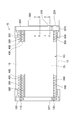
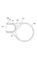
- FIG. 1 is a diagram illustrating an overall configuration of the condenser according to the first embodiment.
- FIG. 2 is a cross-sectional view illustrating a configuration of a joint portion between the header tank and the modulator.
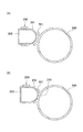
- FIG. 3 is a view showing the AA section and the BB section in FIG.
- FIG. 4 is a diagram for explaining the shape of the header tank.
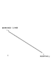
- FIG. 5 is a diagram illustrating the relationship between the protruding amount of the protruding portion and the plate thickness of the reduced thickness portion.
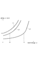
- FIG. 6 is a diagram illustrating the relationship between the protrusion amount of the protrusion and the stress in the thinned portion.
- FIG. 7 is a diagram illustrating a configuration of the joint portion between the header tank and the modulator of the condenser according to the second embodiment.
- the configuration of the condenser 10 according to the first embodiment will be described with reference mainly to FIG.
- the condenser 10 constitutes a part of the refrigeration cycle of the vehicle air conditioner, and is a heat exchanger for condensing the refrigerant circulating in the refrigeration cycle by heat exchange with air. The entire refrigeration cycle is not shown.
- the condenser 10 includes a pair of header tanks 100 and 200, tubes 300, fins 400, and a modulator 500.
- the header tank 100 is a container for temporarily storing refrigerant supplied from the outside.
- the header tank 100 is formed as a substantially cylindrical elongated container, and is arranged with its longitudinal direction aligned with the vertical direction.
- a receiving portion 110 is formed in a portion above the center position in the vertical direction.
- the receiving unit 110 is a part that receives a refrigerant supplied from the outside and allows the refrigerant to flow into the header tank 100.
- the receiving part 110 is formed as a connector for connecting a pipe through which a refrigerant flows in the refrigeration cycle.
- a discharge portion 120 is formed in a portion below the center position in the vertical direction.
- the discharge part 120 is a part for discharging the refrigerant that has been cooled in the condenser 10 to a liquid phase to the outside.
- the discharge part 120 is formed as a connector for connecting a pipe through which a refrigerant flows in the refrigeration cycle, similarly to the receiving part 110 described above.
- a plate-like separator SP1 is disposed at a portion below the center position in the vertical direction.
- the internal space of the header tank 100 is divided into upper and lower portions by the separator SP1.
- the position where the separator SP1 is disposed is lower than the position where the receiving part 110 is formed, and is higher than the position where the discharge part 120 is formed.
- the header tank 200 is provided as a container for temporarily storing the refrigerant, like the header tank 100.
- the header tank 200 is formed as a substantially cylindrical elongated container, and is arranged in a state where the longitudinal direction thereof is along the vertical direction.
- the header tank 200 is arranged such that its longitudinal direction is substantially parallel or parallel to the longitudinal direction of the header tank 100.
- a plate-like separator SP2 is arranged at a portion below the center position in the vertical direction.
- the internal space of the header tank 200 is divided into upper and lower portions by the separator SP2.
- the height of the position where the separator SP2 is disposed is the same as the height of the position where the separator SP1 is disposed.
- the header tank 200 includes a tank member 201 and a base plate 202, and is configured by brazing the two together. Both the tank member 201 and the base plate 202 are made of metal.
- the tank member 201 is a portion protruding in an arc shape toward the modulator 500 described later. After the tank member 201 is entirely formed by press / roll molding, a later-described protrusions 210 and 220 are formed by performing press processing on a part thereof.
- the base plate 202 is a part that holds a plurality of tubes 300.
- a plurality of through holes are formed in the base plate 202 corresponding to the respective tubes 300.
- the tube 300 to be described next is brazed to the base plate 202 in a state where the tip portion is inserted into each through hole.
- illustration of such a tube 300 is abbreviate
- the configuration of the header tank 100 is the same as the configuration of the header tank 200 described above, except that the protruding portions 210 and 220 are not formed in part. For this reason, the detailed illustration and description thereof will be omitted.
- the tube 300 is a metal pipe formed in a cylindrical shape, and is a pipe through which a refrigerant passes.
- a plurality of tubes 300 are provided in the condenser 10. Inside the tube 300, a flow path through which the refrigerant flows is formed.
- the shape of the tube 300 in a cross section perpendicular to the refrigerant flow direction is a flat shape, and the longitudinal direction of the flat shape is along the air flow direction.
- the air flow direction is a direction perpendicular to the paper surface in FIG.
- Each tube 300 has one end connected to the header tank 100 and the other end connected to the header tank 200. Thereby, the internal space of the header tank 100 is communicated with the internal space of the header tank 200 via the respective tubes 300.
- Each tube 300 has its longitudinal direction perpendicular to the longitudinal direction of the header tank 100 or the like, and is held in a stacked state along the longitudinal direction of the header tank 100 or the like, that is, the vertical direction. Yes.
- the fin 400 is a metal plate bent in a wave shape, and is inserted between adjacent tubes 300.
- the top of each of the undulating fins 400 is brazed to the side of the tube 300.
- the “side surface of the tube 300” in the above refers to the upper and lower surfaces in the present embodiment.
- the portion where all the stacked tubes 300 and fins 400 are arranged is a portion where heat is exchanged between the air and the refrigerant, and is a portion referred to as a so-called “heat exchange core portion”.
- Side plates 11 and 12 which are metal plates are provided at positions on both the upper and lower sides of the heat exchange core portion. The side plates 11 and 12 are for reinforcing the heat exchange core part and maintaining its shape by sandwiching the heat exchange core part from above and below.
- the fin 400 is also disposed between the tube 300 disposed on the uppermost side and the side plate 11 and between the tube 300 disposed on the lowermost side and the side plate 12.
- the modulator 500 is a container for receiving a refrigerant from the header tank 200 and separating gas and liquid of the refrigerant.
- the modulator 500 is formed as an elongated cylindrical container having a substantially cylindrical shape, and is arranged in a state where the longitudinal direction thereof is along the vertical direction.
- the modulator 500 is disposed at a position opposite to the heat exchange core portion with the header tank 200 interposed therebetween.
- the position of the modulator 500 may be a position different from the above.
- the modulator 500 may be disposed at a position on the front side or the back side of the header tank 200 in FIG.
- Projections 210 and 220 are formed in a portion of the header tank 200 that faces the modulator 500.
- Each of the protruding portions 210 and 220 is a portion in which a part of the plate material constituting the header tank 200 is protruded toward the modulator 500 by pressing from the inside.
- the “plate material” in the above is specifically the tank member 201.
- the protrusion 210 is formed at a position on the upper side of the separator SP ⁇ b> 2 in the header tank 200.
- the protrusion 220 is formed at a position below the separator SP2.
- Each of these protrusions 210 and 220 is joined to the side surface by a brazing material in a state in which the tip is in contact with the side surface of the modulator 500.
- the modulator 500 is joined to the protrusions 210 and 220 in the header tank 200.
- FIG. 2 is a cross-sectional view schematically showing the internal structure of the joint portion.
- a through hole 211 is formed in the protrusion 210.
- a through hole 511 having the same shape as the through hole 211 is formed in a portion of the modulator 500 that faces the through hole 211.
- the through hole 211 and the through hole 511 function as a refrigerant passage FP ⁇ b> 1 for allowing the refrigerant to flow between the header tank 200 and the modulator 500.
- the entire edges of the through hole 211 and the through hole 511 are closely joined by a brazing material. For this reason, a part of the refrigerant passing through the refrigerant passage FP1 does not leak to the outside.
- the protrusion 220 is formed with a through hole 221.
- a through hole 521 having the same shape as the through hole 221 is also formed in a portion of the modulator 500 facing the through hole 221.
- the through hole 221 and the through hole 521 also function as the refrigerant passage FP ⁇ b> 2 through which the refrigerant flows between the header tank 200 and the modulator 500. Note that the entire edges of the through hole 221 and the through hole 521 are closely joined by a brazing material. For this reason, a part of the refrigerant passing through the refrigerant passage FP2 does not leak to the outside.
- the protruding portion 210 and the protruding portion 220 are formed so as to be separated for each refrigerant passage FP1, FP2.
- the projecting portion 210 and the projecting portion 220 may not be separated. That is, it can be set as the structure by which refrigerant path FP1 and FP2 were each formed with respect to the single protrusion part formed so that the upper and lower sides of separator SP2 might be covered.
- the protrusion part in which refrigerant passage FP1 etc. are not formed separately from the protrusion parts 210 and 220 is further provided in the header tank 200. That is, it is good also as an aspect in which refrigerant passage FP1 grade
- the refrigerant when the refrigeration cycle is operating will be described.
- the refrigerant is compressed by a compressor (not shown) on the upstream side of the condenser 10 in the refrigeration cycle, and is supplied to the condenser 10 with its temperature and pressure increased. At this time, almost the entire refrigerant is in a gas phase.
- the refrigerant flows into the header tank 100 from the receiving unit 110 and is temporarily stored in a space above the separator SP1. Thereafter, the refrigerant flows into the respective tubes 300 and flows toward the header tank 200 through the flow paths in the tubes 300.
- the refrigerant When passing through the inside of the tube 300, the refrigerant is cooled by external air that passes through the heat exchange core. That is, heat is released from the refrigerant to the air. Thereby, the refrigerant passing through the inside of the tube 300 decreases its temperature, and part or all of it condenses and changes from the gas phase to the liquid phase. Moreover, the air which passes a heat exchange core part is heated, and the temperature is raised.
- the refrigerant that has reached the header tank 200 is temporarily stored in the header tank 200 in a space above the separator SP2.
- the refrigerant flows into the modulator 500 through the refrigerant passage FP ⁇ b> 1 of the protrusion 210 and is temporarily stored in the modulator 500.
- the refrigerant flowing into the modulator 500 from the header tank 200 is often in a gas-liquid mixed state.
- gas-liquid separation of the refrigerant is performed.
- the liquid-phase refrigerant is accumulated in the lower portion of the modulator 500.
- the liquid-phase refrigerant passes through the refrigerant passage FP2 of the protrusion 220, flows into the space below the separator SP2 in the header tank 200, and is temporarily stored in the space. Thereafter, the liquid-phase refrigerant flows into the tube 300 provided below the separators SP1 and SP2, and flows again toward the header tank 100 through the flow path in the tube 300. At this time, the liquid phase refrigerant is further cooled by heat exchange with external air.
- the portion below the separators SP1 and SP2 is a portion where the liquid refrigerant is cooled, that is, a portion functioning as a so-called “subcool portion”. Hereinafter, this portion is also referred to as “subcool portion SC”. Note that the “parts below the separators SP1 and SP2” in the above are parts below the one-dot chain line DL in FIG.
- the refrigerant that has passed through the subcool section SC is temporarily stored in the space below the separator SP1 in the header tank 100. Thereafter, the refrigerant is discharged from the discharge unit 120 and flows toward the throttle valve on the downstream side.
- the illustration of the throttle valve is omitted.
- FIG. 3A is a view showing an AA cross section of FIG.
- a gap is formed between the header tank 200 and the modulator 500 at a portion where the protrusions 210 and 220 are not formed. Since most of the portions between the header tank 200 and the modulator 500 are not joined and a gap is formed, heat transfer from the header tank 200 toward the modulator 500 is suppressed. As a result, a situation in which the liquid phase refrigerant in the modulator 500 is vaporized by heat from the header tank 200 is prevented.
- FIG. 3 (B) is a view showing a BB cross section of FIG.
- the header tank 200 specifically, the front end surface of the protrusion 210 is in contact with a part of the modulator 500.
- a contacted portion 501 having a concave surface is formed on the entire portion of the modulator 500 facing the header tank 200 over the entire top and bottom. As a result, substantially the entire tip surface of the protrusion 210 can be brought into contact with the modulator 500.
- the above configuration is the same in the portion where the protrusion 220 is formed.
- a mode of joining between the header tank 200 and the modulator 500 for example, a mode in which a plate which is a separate part is interposed between the two and the header tank 200, the modulator 500, and the plate are brazed can be considered.
- the number of parts is increased and the number of joints by brazing filler metal is increased, there is a high possibility that joint failure will occur at some joints.
- it is preferable that the number of parts to be bonded is as small as possible.
- the modulator 500 is directly joined to the projecting portions 210 and 220 of the header tank 200 instead of interposing another part between the header tank 200 and the modulator 500. I am going to do that.
- the protruding portions 210 and 220 are portions formed by pressing the header tank 200, specifically, a part of the tank member 201. For this reason, also in the embodiment of the present embodiment, since the number of joints by the brazing material does not increase, the occurrence of joint failure due to the increase of joints is prevented.
- FIG. 4 shows a cross section of the header tank 200 at the position of the protrusion 210, as in FIG. 3 (B).
- M shown in the figure is the amount of protrusion of the protrusion 210 and the protrusion 220.
- the “projection amount” refers to the distance from the portion where the protrusions 210 and 220 are not formed in the portion facing the modulator 500 in the cross section shown in FIG. That's it.
- this protrusion amount is also referred to as “protrusion amount M”.
- the protrusion amount M is preferably 0.5 mm or more. If the protruding amount M is smaller than 0.5 mm, the brazing material may enter the gap between the header tank 200 and the modulator 500. As a result, heat insulation between the two is not sufficiently performed, and the liquid refrigerant in the modulator 500 may be vaporized.
- T shown in FIG. 4 is the thickness of the header tank 200.
- the “plate thickness” here is the plate thickness of the plate-like member in which the protruding portion 210 or the like is formed in the header tank 200, that is, the plate thickness of the tank member 201, and the protruding portion 210 or the like is formed. It is the plate
- the plate thickness of the tank member 201 before the protrusions 210 and the like are formed is substantially the plate thickness t.
- the initial plate thickness of the tank member 201 may not be uniform throughout.
- R shown in FIG. 4 is the inner dimension of the header tank 200 along the air flow direction. Specifically, it is the internal dimension along the same direction of the plate-like member in which the protruding portion 210 and the like are formed in the header tank 200. Hereinafter, this inner dimension is also referred to as “inner dimension R”.
- the “plate member on which the protruding portion 210 and the like are formed” in the above is the tank member 201.
- the shape of the tank member 201 before the protrusions 210 and the like are formed is indicated by a one-dot chain line.
- the shape of this alternate long and short dash line is equal to the shape of the tank member 201 in the portion where the protrusions 210 and 220 are not formed.
- the protruding portion 210 or the like When the protruding portion 210 or the like is formed, a part of the tank member 201 is pressed, and the portion is deformed by the protruding amount M in the direction indicated by the arrow in FIG. With such deformation, the plate thickness of a part of the tank member 201 becomes smaller than the plate thickness t described above.
- Such a portion is a root portion of the projecting portion 210 and the like, and is a portion surrounded by a dotted line with a symbol RD in FIG.
- the portion where the plate thickness is reduced as described above by forming the protruding portions 210 and 220 by press working is also referred to as a “thinned portion RD” below.
- FIG. 6 shows the relationship between the protruding amount M of the protruding portion 210 and the stress generated in the thinned portion RD.
- the protrusion amount M of the protrusions 210 and the like is shown on the horizontal axis
- the stress generated in the thinned portion RD is shown on the vertical axis.
- Each line of FIG. 6 shows the stress when an internal pressure of 10 MPa is generated inside the header tank 200. This internal pressure of 10 MPa is the maximum value of the internal pressure that can occur during normal operation of the refrigeration cycle.
- Line L1 is a stress generated in the thinned portion RD when the plate thickness t is 0.9 mm and the inner dimension R is 20 mm. According to what the present inventors have confirmed through experiments and the like, in the header tank 200 having the above-described shape, even when the protrusions 210 and 220 are not formed, one of the header tanks 200 does not endure a pressure exceeding 10 MPa. The part was damaged. The stress generated in the thinned portion RD at this time is expressed as “limit stress ⁇ 0” below.
- the stress of the thinned portion RD indicated by the line L1 or the like increases according to the protruding amount M of the protruding portion 210 or the like. For this reason, in the header tank 200 having the above-described shape indicated by the line L1, even when the protrusions 210 and 220 are not formed, the stress of the thinned portion RD reaches the limit stress ⁇ 0, so the protrusions 210 and 220 are formed. Can not do it.
- the line L2 in FIG. 6 is the stress generated in the thinned portion RD when the plate thickness t is 0.9 mm and the inner dimension R is 15 mm.
- the stress of the thinned portion RD is also reduced accordingly.
- the protruding amount M is approximately 0.5 mm or less, the stress of the thinned portion RD is smaller than the limit stress ⁇ 0, and therefore the header tank 200 is not damaged by the internal pressure.
- the header tank 200 having the above-described shape, if the protruding amount M is approximately 1.5 mm or less, the stress of the thinned portion RD becomes smaller than the limit stress ⁇ 0, and therefore the header tank 200 is not damaged by the internal pressure.
- the protrusion amount M satisfies the following formula (1). Then, the knowledge that the stress of the thinned portion RD can be suppressed to be smaller than the limit stress ⁇ 0 is obtained. Note that “t” in the formula (1) when the initial plate thickness of the tank member 201 is not uniform indicates the initial plate thickness in the portion of the tank member 201 where the thinned portion RD is formed. To do. M ⁇ 2.5 ⁇ 0.12 ⁇ R / t (1)
- the header tank 200 is configured so as to satisfy the condition expressed by the above formula (1), the stress generated in the thinned portion RD can be suppressed to be smaller than the limit stress ⁇ 0 during normal use. Damage to the tank 200 is prevented.
- the second embodiment will be described with reference to FIG. This embodiment is different from the first embodiment only in the configuration of a portion of the modulator 500 that faces the protruding portion 210 and the like, and the rest is the same as the first embodiment.
- FIG. 7 shows a cross section of the header tank 200 and the modulator 500 at the position of the protrusion 210, as in FIG. 3 (B).
- a part of the modulator 500 is formed so as to protrude toward the header tank 200.
- the portion formed in this way is also referred to as “protection portion 502” below.
- the front end portion of the protection part 502 is concave, and the shape of the inner surface thereof is substantially the same as the surface shape of the tank member 201.
- the entire inner surface of the protection unit 502 is in contact with the surface of the tank member 201 and is brazed to the surface.
- a portion of the surface of the tank member 201 covered from the outside by the protective portion 502 includes the entire thinned portion RD.
- refrigerant passages FP1 and FP2 similar to those in the first embodiment are formed in a part of the protective portion 502 so as to penetrate the protruding portion 210 and the protective portion 502, but FIG. Is omitted.
- the protection part 502 formed in the modulator 500 covers the entire thinning part RD from the outside.
- the durability of the header tank 200 against the internal pressure is improved by covering the thinned portion RD whose durability is relatively small from the outside. For this reason, in the case of this embodiment, the protrusion amount M does not need to satisfy said Formula (1).
- the durability of the header tank 200 can be sufficiently secured, only a part of the thinned portion RD is covered by the protective portion 502, and the other part of the thinned portion RD is outside. It is good also as an aspect which is exposed.
Abstract
This condenser (10) that condenses a refrigerant through heat exchange with air is provided with: a plurality of tubes (300) through which the refrigerant passes; a header tank (200) to which each of the tubes is connected; and a modulator (500) which is a container connected to the head tank and that separates the gas and liquid of the refrigerant received from the header tank. Protrusion parts (210, 220) protruding toward the modulator side are formed in a modulator-facing portion of the header tank by press processing. The modulator is joined to the protrusion parts of the header tank.
Description
本出願は、2018年2月6日に出願された日本国特許出願2018-019176号に基づくものであって、その優先権の利益を主張するものであり、その特許出願の全ての内容が、参照により本明細書に組み込まれる。
This application is based on Japanese Patent Application No. 2018-019176 filed on February 6, 2018, and claims the benefit of its priority. Which is incorporated herein by reference.
本開示は、空気との熱交換によって冷媒を凝縮させる凝縮器に関する。
The present disclosure relates to a condenser that condenses refrigerant by heat exchange with air.
空調装置等の冷凍サイクルには、冷媒を凝縮させる凝縮器が設けられる。凝縮器では、内部を流れる高温の気相冷媒と、外部を流れる空気との間で熱交換が行われ、気相冷媒は凝縮して液相冷媒となる。
A refrigeration cycle such as an air conditioner is provided with a condenser that condenses the refrigerant. In the condenser, heat exchange is performed between a high-temperature gas-phase refrigerant flowing inside and air flowing outside, and the gas-phase refrigerant condenses into a liquid-phase refrigerant.
このような凝縮器には、冷媒の気液を分離するための容器であるモジュレータ、が設けられることが多い。モジュレータは「受液器」とも称されるものであり、気液分離後の液相冷媒のみをその下流側に供給するためのものである。供給の対象としては、例えばサブクール部が挙げられる。下記特許文献1に記載されているように、モジュレータは、凝縮器のヘッダタンクに対して固定された状態で設けられる。
Such a condenser is often provided with a modulator which is a container for separating the gas-liquid refrigerant. The modulator is also referred to as a “liquid receiver” and supplies only the liquid-phase refrigerant after gas-liquid separation to the downstream side. As an object of supply, for example, a subcool section can be cited. As described in Patent Document 1 below, the modulator is provided in a fixed state with respect to the header tank of the condenser.
高温の冷媒が貯えられるヘッダタンクから、低温の液相冷媒が貯えられるモジュレータへと熱が伝えられてしまうと、モジュレータ内の液相冷媒が気化してしまうので好ましくない。そこで、下記特許文献1に記載された凝縮器では、ヘッダタンクとモジュレータとの間に断熱用の隙間が形成されており、当該隙間の一部に接合用のプレートを介在させた構成となっている。当該プレートは、予め両面にろう材がクラッドされた板材である。上記の凝縮器では、ヘッダタンク、モジュレータ、及び上記プレートの全体がろう材によって接合されており、これによりモジュレータが固定されている。
If heat is transferred from the header tank in which the high-temperature refrigerant is stored to the modulator in which the low-temperature liquid-phase refrigerant is stored, the liquid-phase refrigerant in the modulator is vaporized, which is not preferable. Therefore, in the condenser described in Patent Document 1 below, a heat insulating gap is formed between the header tank and the modulator, and a joining plate is interposed in a part of the gap. Yes. The said plate is a board | plate material by which the brazing material was clad on both surfaces beforehand. In the condenser described above, the header tank, the modulator, and the entire plate are joined together by a brazing material, thereby fixing the modulator.
上記特許文献1に記載された凝縮器では、ヘッダタンクとモジュレータとの間の接合を、別部品であるプレートを介在させることによって行っている。しかしながら、このように部品点数を増加させ、ろう材による接合箇所を増加させてしまうと、一部の接合箇所において接合不良が生じてしまう可能性が高くなる。接合不良の発生を防止するためには、接合対象となる部品の点数は可能な限り少ない方が好ましい。
In the condenser described in Patent Document 1, the connection between the header tank and the modulator is performed by interposing a plate which is a separate part. However, if the number of parts is increased in this way and the number of joints by the brazing material is increased, there is a high possibility that joint failure will occur at some joints. In order to prevent the occurrence of defective bonding, it is preferable that the number of parts to be bonded is as small as possible.
本開示は、ヘッダタンクからモジュレータへの伝熱を抑制しながらも、部品点数の増加に伴う接合不良を防止することのできる凝縮器、を提供することを目的とする。
This disclosure is intended to provide a condenser capable of preventing poor bonding due to an increase in the number of parts while suppressing heat transfer from the header tank to the modulator.
本開示に係る凝縮器は、空気との熱交換によって冷媒を凝縮させる凝縮器であって、内部を冷媒が通る複数のチューブと、それぞれのチューブが接続されたヘッダタンクと、ヘッダタンクに接合された容器であって、ヘッダタンクから受け入れた冷媒の気液を分離するモジュレータと、を備える。ヘッダタンクのうちモジュレータと対向する部分には、モジュレータ側に向けて突出する突出部がプレス加工によって形成されており、モジュレータは、ヘッダタンクのうち突出部に接合されている。
A condenser according to the present disclosure is a condenser that condenses a refrigerant by heat exchange with air, and is joined to a plurality of tubes through which the refrigerant passes, a header tank to which each tube is connected, and the header tank. And a modulator for separating the gas-liquid refrigerant received from the header tank. A portion of the header tank that faces the modulator is formed with a protrusion that protrudes toward the modulator, and the modulator is joined to the protrusion of the header tank.
このような構成の凝縮器では、モジュレータが、ヘッダタンクに形成された突出部に接合されている。突出部は、ヘッダタンクの一部を、プレス加工によってモジュレータ側に向けて突出させた部分である。このような突出部にモジュレータが接合されているので、突出部以外の部分では、ヘッダタンクとモジュレータとの間に隙間が形成されている。その結果、ヘッダタンクからモジュレータに向けた伝熱が抑制される。
In the condenser having such a configuration, the modulator is joined to the protrusion formed in the header tank. The protruding portion is a portion in which a part of the header tank is protruded toward the modulator side by pressing. Since the modulator is joined to such a protruding portion, a gap is formed between the header tank and the modulator at a portion other than the protruding portion. As a result, heat transfer from the header tank toward the modulator is suppressed.
また、上記の突出部は、ヘッダタンクに対して別部品を接合するのではなく、ヘッダタンクの一部にプレス加工を施すことによって形成されている。このような構成では、ヘッダタンクに対してモジュレータが直接接合されるので、接合箇所の増加に伴う接合不良の発生が防止される。
Further, the protruding portion is formed not by joining another part to the header tank but by pressing a part of the header tank. In such a configuration, since the modulator is directly joined to the header tank, it is possible to prevent the occurrence of joint failure due to an increase in joint locations.
本開示によれば、ヘッダタンクからモジュレータへの伝熱を抑制しながらも、部品点数の増加に伴う接合不良を防止することのできる凝縮器、が提供される。
According to the present disclosure, it is possible to provide a condenser that can prevent poor bonding due to an increase in the number of parts while suppressing heat transfer from the header tank to the modulator.
以下、添付図面を参照しながら本実施形態について説明する。説明の理解を容易にするため、各図面において同一の構成要素に対しては可能な限り同一の符号を付して、重複する説明は省略する。
Hereinafter, the present embodiment will be described with reference to the accompanying drawings. In order to facilitate the understanding of the description, the same constituent elements in the drawings will be denoted by the same reference numerals as much as possible, and redundant description will be omitted.
図1を主に参照しながら、第1実施形態に係る凝縮器10の構成について説明する。凝縮器10は、車両用空調装置の冷凍サイクルの一部を構成するものであって、冷凍サイクルを循環する冷媒を、空気との熱交換によって凝縮させるための熱交換器である。尚、上記冷凍サイクルの全体については不図示となっている。凝縮器10は、一対のヘッダタンク100、200と、チューブ300と、フィン400と、モジュレータ500と、を備えている。
The configuration of the condenser 10 according to the first embodiment will be described with reference mainly to FIG. The condenser 10 constitutes a part of the refrigeration cycle of the vehicle air conditioner, and is a heat exchanger for condensing the refrigerant circulating in the refrigeration cycle by heat exchange with air. The entire refrigeration cycle is not shown. The condenser 10 includes a pair of header tanks 100 and 200, tubes 300, fins 400, and a modulator 500.
ヘッダタンク100は、外部から供給される冷媒を一時的に貯えるための容器である。ヘッダタンク100は、略円柱形上の細長い容器として形成されており、その長手方向を上下方向に沿わせた状態で配置されている。
The header tank 100 is a container for temporarily storing refrigerant supplied from the outside. The header tank 100 is formed as a substantially cylindrical elongated container, and is arranged with its longitudinal direction aligned with the vertical direction.
ヘッダタンク100のうち、その上下方向において中央となる位置よりも上方側の部分には、受入部110が形成されている。受入部110は、外部から供給される冷媒を受け入れて、これをヘッダタンク100の内部に流入させる部分である。受入部110は、冷凍サイクルにおいて冷媒が流れる配管を接続するためのコネクタとして形成されている。
In the header tank 100, a receiving portion 110 is formed in a portion above the center position in the vertical direction. The receiving unit 110 is a part that receives a refrigerant supplied from the outside and allows the refrigerant to flow into the header tank 100. The receiving part 110 is formed as a connector for connecting a pipe through which a refrigerant flows in the refrigeration cycle.
ヘッダタンク100のうち、その上下方向において中央となる位置よりも下方側の部分には、排出部120が形成されている。排出部120は、凝縮器10において冷却され液相となった冷媒を、外部に排出するための部分である。排出部120は、上記の受入部110と同様に、冷凍サイクルにおいて冷媒が流れる配管を接続するためのコネクタとして形成されている。
In the header tank 100, a discharge portion 120 is formed in a portion below the center position in the vertical direction. The discharge part 120 is a part for discharging the refrigerant that has been cooled in the condenser 10 to a liquid phase to the outside. The discharge part 120 is formed as a connector for connecting a pipe through which a refrigerant flows in the refrigeration cycle, similarly to the receiving part 110 described above.
ヘッダタンク100の内部のうち、その上下方向において中央となる位置よりも下方側の部分には、板状のセパレータSP1が配置されている。ヘッダタンク100の内部空間は、このセパレータSP1によって上下に分けられている。セパレータSP1が配置されている位置は、受入部110が形成されている位置よりも低く、排出部120が形成されている位置よりも高い。
In the inside of the header tank 100, a plate-like separator SP1 is disposed at a portion below the center position in the vertical direction. The internal space of the header tank 100 is divided into upper and lower portions by the separator SP1. The position where the separator SP1 is disposed is lower than the position where the receiving part 110 is formed, and is higher than the position where the discharge part 120 is formed.
ヘッダタンク200は、ヘッダタンク100と同様に、冷媒を一時的に貯えるための容器として設けられている。ヘッダタンク200は、略円柱形上の細長い容器として形成されており、その長手方向を上下方向に沿わせた状態で配置されている。ヘッダタンク200は、その長手方向がヘッダタンク100の長手方向と略平行もしくは平行となるように配置されている。
The header tank 200 is provided as a container for temporarily storing the refrigerant, like the header tank 100. The header tank 200 is formed as a substantially cylindrical elongated container, and is arranged in a state where the longitudinal direction thereof is along the vertical direction. The header tank 200 is arranged such that its longitudinal direction is substantially parallel or parallel to the longitudinal direction of the header tank 100.
ヘッダタンク200の内部のうち、その上下方向において中央となる位置よりも下方側の部分には、板状のセパレータSP2が配置されている。ヘッダタンク200の内部空間は、このセパレータSP2によって上下に分けられている。セパレータSP2が配置されている位置の高さは、セパレータSP1が配置されている位置の高さと同じである。
In the inside of the header tank 200, a plate-like separator SP2 is arranged at a portion below the center position in the vertical direction. The internal space of the header tank 200 is divided into upper and lower portions by the separator SP2. The height of the position where the separator SP2 is disposed is the same as the height of the position where the separator SP1 is disposed.
図3に示されるように、ヘッダタンク200は、タンク部材201とベースプレート202とを備えており、両者をろう接することによって構成されている。タンク部材201及びベースプレート202は、いずれも金属によって形成されている。タンク部材201は、後述のモジュレータ500に向けて円弧状に突出する部分である。タンク部材201は、プレス/ロール成形によって全体が形成された後、一部にプレス加工を施すことにより、後述の突出部210、220が形成されている。
As shown in FIG. 3, the header tank 200 includes a tank member 201 and a base plate 202, and is configured by brazing the two together. Both the tank member 201 and the base plate 202 are made of metal. The tank member 201 is a portion protruding in an arc shape toward the modulator 500 described later. After the tank member 201 is entirely formed by press / roll molding, a later-described protrusions 210 and 220 are formed by performing press processing on a part thereof.
ベースプレート202は、複数のチューブ300を保持する部分である。ベースプレート202には、それぞれのチューブ300に対応して複数の不図示の貫通穴が形成されている。次に述べるチューブ300は、その先端部分がそれぞれの貫通穴に挿通された状態で、ベースプレート202に対してろう接されている。尚、図3ではこのようなチューブ300の図示が省略されている。
The base plate 202 is a part that holds a plurality of tubes 300. A plurality of through holes (not shown) are formed in the base plate 202 corresponding to the respective tubes 300. The tube 300 to be described next is brazed to the base plate 202 in a state where the tip portion is inserted into each through hole. In addition, illustration of such a tube 300 is abbreviate | omitted in FIG.
尚、ヘッダタンク100の構成は、一部に突出部210、220が形成されていない点を除き、以上に述べたヘッダタンク200の構成と同一である。このため、その具体的な図示や説明については省略する。
The configuration of the header tank 100 is the same as the configuration of the header tank 200 described above, except that the protruding portions 210 and 220 are not formed in part. For this reason, the detailed illustration and description thereof will be omitted.
図1に戻って説明を続ける。チューブ300は、筒状に形成された金属製の配管であって、内部を冷媒が通る管となっている。チューブ300は、凝縮器10に複数本備えられている。チューブ300の内部には、冷媒が流れる流路が形成されている。冷媒の流れ方向に対して垂直な断面におけるチューブ300の形状は扁平形状となっており、当該扁平形状の長手方向は空気の流れ方向に沿っている。空気の流れ方向は、図1においては紙面に垂直な方向である。
Referring back to FIG. The tube 300 is a metal pipe formed in a cylindrical shape, and is a pipe through which a refrigerant passes. A plurality of tubes 300 are provided in the condenser 10. Inside the tube 300, a flow path through which the refrigerant flows is formed. The shape of the tube 300 in a cross section perpendicular to the refrigerant flow direction is a flat shape, and the longitudinal direction of the flat shape is along the air flow direction. The air flow direction is a direction perpendicular to the paper surface in FIG.
それぞれのチューブ300は、その一端がヘッダタンク100に接続されており、その他端がヘッダタンク200に接続されている。これにより、ヘッダタンク100の内部空間は、それぞれのチューブ300を介して、ヘッダタンク200の内部空間と連通されている。
Each tube 300 has one end connected to the header tank 100 and the other end connected to the header tank 200. Thereby, the internal space of the header tank 100 is communicated with the internal space of the header tank 200 via the respective tubes 300.
また、それぞれのチューブ300は、その長手方向がヘッダタンク100等の長手方向とは垂直となっており、ヘッダタンク100等の長手方向、つまり上下方向に沿って互いに積層された状態で保持されている。
Each tube 300 has its longitudinal direction perpendicular to the longitudinal direction of the header tank 100 or the like, and is held in a stacked state along the longitudinal direction of the header tank 100 or the like, that is, the vertical direction. Yes.
フィン400は、波状に折り曲げられた金属板であって、隣り合うチューブ300の間に挿入されている。波状となっているフィン400のそれぞれの頂部は、チューブ300の側面にろう付けされている。尚、上記における「チューブ300の側面」とは、本実施形態では上下面のことである。冷凍サイクルの動作中においては、冷媒の熱がチューブ300を介して空気に伝達される他、チューブ300及びフィン400を介しても空気に伝達される。つまり、空気との接触面積がフィン400によって大きくなっており、これにより空気と冷媒との熱交換が効率的に行われる。
The fin 400 is a metal plate bent in a wave shape, and is inserted between adjacent tubes 300. The top of each of the undulating fins 400 is brazed to the side of the tube 300. The “side surface of the tube 300” in the above refers to the upper and lower surfaces in the present embodiment. During the operation of the refrigeration cycle, the heat of the refrigerant is transmitted to the air through the tube 300 and also to the air through the tube 300 and the fins 400. That is, the contact area with air is increased by the fins 400, whereby heat exchange between the air and the refrigerant is performed efficiently.
積層された全てのチューブ300及びフィン400が配置された部分は、空気と冷媒との間で熱交換が行われる部分であって、所謂「熱交換コア部」と称される部分である。
熱交換コア部の上下両側となる位置には、金属板であるサイドプレート11、12が設けられている。サイドプレート11、12は、熱交換コア部を上下両側から挟み込むことにより、熱交換コア部を補強してその形状を維持するためのものである。 The portion where all thestacked tubes 300 and fins 400 are arranged is a portion where heat is exchanged between the air and the refrigerant, and is a portion referred to as a so-called “heat exchange core portion”.
Side plates 11 and 12 which are metal plates are provided at positions on both the upper and lower sides of the heat exchange core portion. The side plates 11 and 12 are for reinforcing the heat exchange core part and maintaining its shape by sandwiching the heat exchange core part from above and below.
熱交換コア部の上下両側となる位置には、金属板であるサイドプレート11、12が設けられている。サイドプレート11、12は、熱交換コア部を上下両側から挟み込むことにより、熱交換コア部を補強してその形状を維持するためのものである。 The portion where all the
サイドプレート11の一端はヘッダタンク100に固定されており、他端はヘッダタンク200に固定されている。サイドプレート12も同様である。最も上方側に配置されたチューブ300とサイドプレート11との間、及び、最も下方側に配置されたチューブ300とサイドプレート12との間にも、上記のフィン400が配置されている。
One end of the side plate 11 is fixed to the header tank 100, and the other end is fixed to the header tank 200. The same applies to the side plate 12. The fin 400 is also disposed between the tube 300 disposed on the uppermost side and the side plate 11 and between the tube 300 disposed on the lowermost side and the side plate 12.
モジュレータ500は、ヘッダタンク200から冷媒を受け入れて、当該冷媒の気液を分離するための容器である。モジュレータ500は、略円柱形上の細長い容器として形成されており、その長手方向を上下方向に沿わせた状態で配置されている。モジュレータ500は、ヘッダタンク200を間に挟んで、熱交換コア部とは反対側となる位置に配置されている。モジュレータ500の位置は、上記とは異なる位置であってもよい。例えば、図1においてヘッダタンク200の紙面手前側若しくは奥側となる位置に、モジュレータ500が配置されていてもよい。
The modulator 500 is a container for receiving a refrigerant from the header tank 200 and separating gas and liquid of the refrigerant. The modulator 500 is formed as an elongated cylindrical container having a substantially cylindrical shape, and is arranged in a state where the longitudinal direction thereof is along the vertical direction. The modulator 500 is disposed at a position opposite to the heat exchange core portion with the header tank 200 interposed therebetween. The position of the modulator 500 may be a position different from the above. For example, the modulator 500 may be disposed at a position on the front side or the back side of the header tank 200 in FIG.
ヘッダタンク200のうちモジュレータ500と対向する部分には、突出部210、220が形成されている。突出部210、220はいずれも、ヘッダタンク200を構成する板材の一部を、内側からのプレス加工により、モジュレータ500側に向けて突出させた部分となっている。上記における「板材」とは、具体的にはタンク部材201である。
Projections 210 and 220 are formed in a portion of the header tank 200 that faces the modulator 500. Each of the protruding portions 210 and 220 is a portion in which a part of the plate material constituting the header tank 200 is protruded toward the modulator 500 by pressing from the inside. The “plate material” in the above is specifically the tank member 201.
図1に示されるように、突出部210は、ヘッダタンク200内のセパレータSP2よりも上方側となる位置に形成されている。一方、突出部220は、セパレータSP2よりも下方側となる位置に形成されている。これら突出部210、220はいずれも、その先端をモジュレータ500の側面に当接させた状態で、当該側面に対してろう材により接合されている。換言すれば、モジュレータ500は、ヘッダタンク200のうち上記の突出部210、220に対して接合されている。
As shown in FIG. 1, the protrusion 210 is formed at a position on the upper side of the separator SP <b> 2 in the header tank 200. On the other hand, the protrusion 220 is formed at a position below the separator SP2. Each of these protrusions 210 and 220 is joined to the side surface by a brazing material in a state in which the tip is in contact with the side surface of the modulator 500. In other words, the modulator 500 is joined to the protrusions 210 and 220 in the header tank 200.
図2に示されるのは、上記接合部分の内部構造を模式的に示す断面図である。同図に示されるように、突出部210には貫通穴211が形成されている。また、モジュレータ500のうち貫通穴211と対向する部分にも、貫通穴211と同一形状の貫通穴511が形成されている。このため、ヘッダタンク200の内部空間のうちセパレータSP2よりも上方側の部分と、モジュレータ500の内部空間との間は、貫通穴211及び貫通穴511によって連通されている。貫通穴211及び貫通穴511は、ヘッダタンク200とモジュレータ500との間で冷媒が流通するための冷媒通路FP1として機能する。尚、貫通穴211及び貫通穴511は、それぞれの縁全体がろう材によって密に接合されている。このため、上記冷媒通路FP1を通る冷媒の一部が外部に漏出してしまうことはない。
FIG. 2 is a cross-sectional view schematically showing the internal structure of the joint portion. As shown in the figure, a through hole 211 is formed in the protrusion 210. Also, a through hole 511 having the same shape as the through hole 211 is formed in a portion of the modulator 500 that faces the through hole 211. For this reason, a portion above the separator SP <b> 2 in the internal space of the header tank 200 and the internal space of the modulator 500 are communicated with each other by the through hole 211 and the through hole 511. The through hole 211 and the through hole 511 function as a refrigerant passage FP <b> 1 for allowing the refrigerant to flow between the header tank 200 and the modulator 500. Note that the entire edges of the through hole 211 and the through hole 511 are closely joined by a brazing material. For this reason, a part of the refrigerant passing through the refrigerant passage FP1 does not leak to the outside.
上記と同様に、突出部220には貫通穴221が形成されている。また、モジュレータ500のうち貫通穴221と対向する部分にも、貫通穴221と同一形状の貫通穴521が形成されている。このため、ヘッダタンク200の内部空間のうちセパレータSP2よりも下方側の部分と、モジュレータ500の内部空間との間は、貫通穴221及び貫通穴521によって連通されている。貫通穴221及び貫通穴521も、ヘッダタンク200とモジュレータ500との間で冷媒が流通するための冷媒通路FP2として機能する。尚、貫通穴221及び貫通穴521は、それぞれの縁全体がろう材によって密に接合されている。このため、上記冷媒通路FP2を通る冷媒の一部が外部に漏出してしまうことはない。
Similarly to the above, the protrusion 220 is formed with a through hole 221. A through hole 521 having the same shape as the through hole 221 is also formed in a portion of the modulator 500 facing the through hole 221. For this reason, the part below the separator SP2 in the internal space of the header tank 200 and the internal space of the modulator 500 are communicated with each other by the through hole 221 and the through hole 521. The through hole 221 and the through hole 521 also function as the refrigerant passage FP <b> 2 through which the refrigerant flows between the header tank 200 and the modulator 500. Note that the entire edges of the through hole 221 and the through hole 521 are closely joined by a brazing material. For this reason, a part of the refrigerant passing through the refrigerant passage FP2 does not leak to the outside.
図2に示されるように、突出部210と突出部220との間となる部分では、セパレータSP2の一部がモジュレータ500側に向けて外側に突出している。本実施形態では、このようなセパレータSP2の突出部分を避けるために、突出部210と突出部220とが、それぞれの冷媒通路FP1、FP2毎に分かれるように形成されている。
As shown in FIG. 2, in the portion between the protrusion 210 and the protrusion 220, a part of the separator SP2 protrudes outward toward the modulator 500 side. In the present embodiment, in order to avoid such a protruding portion of the separator SP2, the protruding portion 210 and the protruding portion 220 are formed so as to be separated for each refrigerant passage FP1, FP2.
仮に、セパレータSP2の全部がヘッダタンク200の内部に収容されているような構成においては、突出部210と突出部220とが分かれていない構成とすることができる。つまり、セパレータSP2の上下両側に亘るように形成された単一の突出部に対し、冷媒通路FP1、FP2がそれぞれ形成された構成とすることができる。
Temporarily, in the configuration in which the entire separator SP2 is accommodated in the header tank 200, the projecting portion 210 and the projecting portion 220 may not be separated. That is, it can be set as the structure by which refrigerant path FP1 and FP2 were each formed with respect to the single protrusion part formed so that the upper and lower sides of separator SP2 might be covered.
尚、突出部210、220とは別に、冷媒通路FP1等が形成されていない突出部が、ヘッダタンク200に更に設けられているような態様としてもよい。つまり、複数設けられた突出部210等のうち、一部の突出部210等のみに冷媒通路FP1等が形成されているような態様としてもよい。
In addition, it is good also as an aspect in which the protrusion part in which refrigerant passage FP1 etc. are not formed separately from the protrusion parts 210 and 220 is further provided in the header tank 200. That is, it is good also as an aspect in which refrigerant passage FP1 grade | etc., Is formed only in the one part projection part 210 grade | etc., Among the several projection part 210 grade | etc., Provided.
図1を再び参照しながら、冷凍サイクルが動作しているときにおける冷媒の流れについて説明する。冷媒は、冷凍サイクルのうち凝縮器10よりも上流側において不図示の圧縮機により圧縮され、その温度及び圧力を上昇させた状態で凝縮器10に供給される。このとき、冷媒はそのほぼ全体が気相の状態となっている。当該冷媒は、受入部110からヘッダタンク100の内部に流入し、セパレータSP1よりも上方側の空間において一時的に貯えられる。その後、冷媒はそれぞれのチューブ300の内部に流入し、チューブ300内の流路を通ってヘッダタンク200に向かって流れる。
Referring to FIG. 1 again, the flow of the refrigerant when the refrigeration cycle is operating will be described. The refrigerant is compressed by a compressor (not shown) on the upstream side of the condenser 10 in the refrigeration cycle, and is supplied to the condenser 10 with its temperature and pressure increased. At this time, almost the entire refrigerant is in a gas phase. The refrigerant flows into the header tank 100 from the receiving unit 110 and is temporarily stored in a space above the separator SP1. Thereafter, the refrigerant flows into the respective tubes 300 and flows toward the header tank 200 through the flow paths in the tubes 300.
冷媒は、チューブ300の内部を通る際において、熱交換コア部を通過する外部の空気によって冷却される。つまり、冷媒から空気への放熱が行われる。これにより、チューブ300の内部を通る冷媒はその温度を低下させ、その一部又は全部が凝縮して気相から液相へと変化する。また、熱交換コア部を通過する空気は加熱され、その温度を上昇させる。
When passing through the inside of the tube 300, the refrigerant is cooled by external air that passes through the heat exchange core. That is, heat is released from the refrigerant to the air. Thereby, the refrigerant passing through the inside of the tube 300 decreases its temperature, and part or all of it condenses and changes from the gas phase to the liquid phase. Moreover, the air which passes a heat exchange core part is heated, and the temperature is raised.
ヘッダタンク200に到達した冷媒は、ヘッダタンク200の内部のうち、セパレータSP2よりも上方側の空間において一時的に貯えられる。当該冷媒は、突出部210の冷媒通路FP1を通ってモジュレータ500の内部に流入し、モジュレータ500内に一時的に貯えられる。
The refrigerant that has reached the header tank 200 is temporarily stored in the header tank 200 in a space above the separator SP2. The refrigerant flows into the modulator 500 through the refrigerant passage FP <b> 1 of the protrusion 210 and is temporarily stored in the modulator 500.
ヘッダタンク200からモジュレータ500に流入する冷媒は、多くの場合、気液混合の状態となっている。モジュレータ500では、当該冷媒の気液分離が行われる。その結果、モジュレータ500の下方側部分には液相冷媒が溜まった状態となっている。
The refrigerant flowing into the modulator 500 from the header tank 200 is often in a gas-liquid mixed state. In the modulator 500, gas-liquid separation of the refrigerant is performed. As a result, the liquid-phase refrigerant is accumulated in the lower portion of the modulator 500.
上記の液相冷媒は、突出部220の冷媒通路FP2を通って、ヘッダタンク200のうちセパレータSP2よりも下方側の空間に流入し、当該空間に一時的に貯えられる。その後、液相冷媒は、セパレータSP1、SP2よりも下方側に設けられたチューブ300の内部に流入し、チューブ300内の流路を通って再びヘッダタンク100に向かって流れる。このとき、液相冷媒は、外部の空気との熱交換によって更に冷却される。熱交換コア部のうち、セパレータSP1、SP2よりも下方側の部分は、上記のような液相冷媒が冷却される部分、すなわち、所謂「サブクール部」として機能する部分となっている。当該部分のことを、以下では「サブクール部SC」とも表記する。尚、上記における「セパレータSP1、SP2よりも下方側の部分」とは、図1において一点鎖線DLよりも下方側の部分であって、符号SCが付された部分のことである。
The liquid-phase refrigerant passes through the refrigerant passage FP2 of the protrusion 220, flows into the space below the separator SP2 in the header tank 200, and is temporarily stored in the space. Thereafter, the liquid-phase refrigerant flows into the tube 300 provided below the separators SP1 and SP2, and flows again toward the header tank 100 through the flow path in the tube 300. At this time, the liquid phase refrigerant is further cooled by heat exchange with external air. Of the heat exchange core portion, the portion below the separators SP1 and SP2 is a portion where the liquid refrigerant is cooled, that is, a portion functioning as a so-called “subcool portion”. Hereinafter, this portion is also referred to as “subcool portion SC”. Note that the “parts below the separators SP1 and SP2” in the above are parts below the one-dot chain line DL in FIG.
サブクール部SCを通った冷媒は、ヘッダタンク100の内部のうち、セパレータSP1よりも下方側の空間において一時的に貯えられる。その後、当該冷媒は排出部120から排出され、下流側の絞り弁に向かって流れる。尚、絞り弁の図示は省略されている。
The refrigerant that has passed through the subcool section SC is temporarily stored in the space below the separator SP1 in the header tank 100. Thereafter, the refrigerant is discharged from the discharge unit 120 and flows toward the throttle valve on the downstream side. The illustration of the throttle valve is omitted.
突出部210、220が形成されていることの効果について、図3を参照しながら説明する。図3(A)は、図1のA-A断面を示す図である。同図に示されるように、突出部210、220が形成されていない部分では、ヘッダタンク200とモジュレータ500との間に隙間が形成されている。ヘッダタンク200とモジュレータ500との間のうち殆どの部分では、両者は接合されておらず隙間が形成されているので、ヘッダタンク200からモジュレータ500に向けた伝熱が抑制されている。その結果、ヘッダタンク200からの熱によって、モジュレータ500内の液相冷媒が気化してしまうような事態が防止される。
The effect of the protrusions 210 and 220 being formed will be described with reference to FIG. FIG. 3A is a view showing an AA cross section of FIG. As shown in the figure, a gap is formed between the header tank 200 and the modulator 500 at a portion where the protrusions 210 and 220 are not formed. Since most of the portions between the header tank 200 and the modulator 500 are not joined and a gap is formed, heat transfer from the header tank 200 toward the modulator 500 is suppressed. As a result, a situation in which the liquid phase refrigerant in the modulator 500 is vaporized by heat from the header tank 200 is prevented.
図3(B)は、図1のB-B断面を示す図である。同図に示されるように、突出部210が形成されている部分では、ヘッダタンク200、具体的には突出部210の先端面が、モジュレータ500の一部に対して当接しろう接されている。尚、モジュレータ500のうちヘッダタンク200と対向する部分には、凹状の面を有する被当接部501が上下全体に亘って形成されている。これにより、突出部210の先端面の略全体を、モジュレータ500に対して当接させることが可能となっている。以上のような構成は、突出部220が形成されている部分においても同様である。
FIG. 3 (B) is a view showing a BB cross section of FIG. As shown in the figure, in the portion where the protrusion 210 is formed, the header tank 200, specifically, the front end surface of the protrusion 210 is in contact with a part of the modulator 500. . Note that a contacted portion 501 having a concave surface is formed on the entire portion of the modulator 500 facing the header tank 200 over the entire top and bottom. As a result, substantially the entire tip surface of the protrusion 210 can be brought into contact with the modulator 500. The above configuration is the same in the portion where the protrusion 220 is formed.
ヘッダタンク200とモジュレータ500との間の接合の態様としては、例えば、別部品であるプレートを両者の間に介在させ、ヘッダタンク200、モジュレータ500、及びプレートをろう接するような態様も考えられる。しかしながら、そのように部品点数を増加させ、ろう材による接合箇所を増加させてしまうと、一部の接合箇所において接合不良が生じてしまう可能性が高くなる。接合不良の発生を防止するためには、接合対象となる部品の点数は可能な限り少ない方が好ましい。
As a mode of joining between the header tank 200 and the modulator 500, for example, a mode in which a plate which is a separate part is interposed between the two and the header tank 200, the modulator 500, and the plate are brazed can be considered. However, if the number of parts is increased and the number of joints by brazing filler metal is increased, there is a high possibility that joint failure will occur at some joints. In order to prevent the occurrence of defective bonding, it is preferable that the number of parts to be bonded is as small as possible.
そこで、本実施形態に係る凝縮器10では、ヘッダタンク200とモジュレータ500との間に別の部品を介在させるのではなく、ヘッダタンク200の突出部210、220に対し、モジュレータ500を直接接合することとしている。突出部210、220は、ヘッダタンク200、具体的にはタンク部材201の一部にプレス加工を施すことによって形成された部分である。このため、本実施形態の態様としても、ろう材による接合箇所が増加することは無いので、接合箇所の増加に伴う接合不良の発生が防止される。
Therefore, in the condenser 10 according to the present embodiment, the modulator 500 is directly joined to the projecting portions 210 and 220 of the header tank 200 instead of interposing another part between the header tank 200 and the modulator 500. I am going to do that. The protruding portions 210 and 220 are portions formed by pressing the header tank 200, specifically, a part of the tank member 201. For this reason, also in the embodiment of the present embodiment, since the number of joints by the brazing material does not increase, the occurrence of joint failure due to the increase of joints is prevented.
図4は、図3(B)と同様に、突出部210の位置におけるヘッダタンク200の断面を示したものである。同図に示される「M」は、突出部210及び突出部220の突出量である。ここでいう「突出量」とは、図4に示される断面において、モジュレータ500に対向する部分のうち突出部210、220が形成されていない部分から、突出部210、220の先端面までの距離のことである。以下では、この突出量のことを「突出量M」とも表記する。
FIG. 4 shows a cross section of the header tank 200 at the position of the protrusion 210, as in FIG. 3 (B). “M” shown in the figure is the amount of protrusion of the protrusion 210 and the protrusion 220. As used herein, the “projection amount” refers to the distance from the portion where the protrusions 210 and 220 are not formed in the portion facing the modulator 500 in the cross section shown in FIG. That's it. Hereinafter, this protrusion amount is also referred to as “protrusion amount M”.
突出量Mは、0.5ミリメートル以上であることが好ましい。突出量Mが0.5ミリメートルよりも小さいと、ヘッダタンク200とモジュレータ500との隙間にろう材が侵入してしまうおそれがある。その結果、両者間の断熱が十分には行われず、モジュレータ500内の液相冷媒が気化するおそれがある。
The protrusion amount M is preferably 0.5 mm or more. If the protruding amount M is smaller than 0.5 mm, the brazing material may enter the gap between the header tank 200 and the modulator 500. As a result, heat insulation between the two is not sufficiently performed, and the liquid refrigerant in the modulator 500 may be vaporized.
図4に示される「t」は、ヘッダタンク200の板厚である。ここでいう「板厚」とは、ヘッダタンク200のうち、突出部210等が形成される板状部材の板厚、つまりタンク部材201の板厚であって、突出部210等が形成されるよりも前の時点におけるタンク部材201の板厚のことである。以下では、この板厚のことを「板厚t」とも表記する。尚、本実施形態では、突出部210等が形成されるよりも前のタンク部材201の板厚が、略全体において板厚tとなっている。しかしながら、タンク部材201の当初の板厚は、全体において均一でなくてもよい。
“T” shown in FIG. 4 is the thickness of the header tank 200. The “plate thickness” here is the plate thickness of the plate-like member in which the protruding portion 210 or the like is formed in the header tank 200, that is, the plate thickness of the tank member 201, and the protruding portion 210 or the like is formed. It is the plate | board thickness of the tank member 201 in time before. Hereinafter, this plate thickness is also expressed as “plate thickness t”. In the present embodiment, the plate thickness of the tank member 201 before the protrusions 210 and the like are formed is substantially the plate thickness t. However, the initial plate thickness of the tank member 201 may not be uniform throughout.
図4に示される「R」は、空気の流れ方向に沿ったヘッダタンク200の内寸である。具体的には、ヘッダタンク200のうち、突出部210等が形成される板状部材の同方向に沿った内寸である。以下では、この内寸のことを「内寸R」とも表記する。尚、上記における「突出部210等が形成される板状部材」とは、タンク部材201のことである。
“R” shown in FIG. 4 is the inner dimension of the header tank 200 along the air flow direction. Specifically, it is the internal dimension along the same direction of the plate-like member in which the protruding portion 210 and the like are formed in the header tank 200. Hereinafter, this inner dimension is also referred to as “inner dimension R”. The “plate member on which the protruding portion 210 and the like are formed” in the above is the tank member 201.
図4では、突出部210等が形成される前におけるタンク部材201の形状が、一点鎖線で示されている。この一点鎖線の形状は、突出部210、220が形成されていない部分におけるタンク部材201の形状に等しい。
In FIG. 4, the shape of the tank member 201 before the protrusions 210 and the like are formed is indicated by a one-dot chain line. The shape of this alternate long and short dash line is equal to the shape of the tank member 201 in the portion where the protrusions 210 and 220 are not formed.
突出部210等が形成される際には、タンク部材201の一部にプレス加工が施され、当該部分が図4の矢印で示される方向に突出量Mだけ変形する。このような変形に伴って、タンク部材201の一部においては、板厚が上記の板厚tよりも小さくなる。このような部分は、突出部210等の根元部分であり、図4において符号RDの付された点線で囲まれた部分である。ヘッダタンク200のうち、プレス加工により突出部210、220を形成したことで上記のように板厚が小さくなっている部分のことを、以下では「減肉部RD」とも表記する。
When the protruding portion 210 or the like is formed, a part of the tank member 201 is pressed, and the portion is deformed by the protruding amount M in the direction indicated by the arrow in FIG. With such deformation, the plate thickness of a part of the tank member 201 becomes smaller than the plate thickness t described above. Such a portion is a root portion of the projecting portion 210 and the like, and is a portion surrounded by a dotted line with a symbol RD in FIG. In the header tank 200, the portion where the plate thickness is reduced as described above by forming the protruding portions 210 and 220 by press working is also referred to as a “thinned portion RD” below.
図5に示されるように、横軸の突出量Mが大きくなるほど、減肉部RDにおける縦軸の板厚は小さくなる。その結果、内圧に対するヘッダタンク200の強度は弱くなる。よく知られているように、冷凍サイクルの動作中においては、凝縮器10の内部における冷媒の圧力は高くなるので、ヘッダタンク200には一定の強度が求められる。従って、突出量Mが大きくなり過ぎると、減肉部RDにおける板厚が小さくなり、ヘッダタンク200の強度が不足してしまうことが懸念される。
As shown in FIG. 5, the larger the protrusion amount M on the horizontal axis, the smaller the plate thickness on the vertical axis in the thinned portion RD. As a result, the strength of the header tank 200 against the internal pressure is weakened. As is well known, during the operation of the refrigeration cycle, the pressure of the refrigerant inside the condenser 10 is high, so that the header tank 200 is required to have a certain strength. Therefore, if the protrusion amount M becomes too large, there is a concern that the thickness of the thinned portion RD becomes small and the strength of the header tank 200 is insufficient.
図6の線L1乃至L3に示されるのは、突出部210等の突出量Mと、減肉部RDにおいて生じる応力との関係である。図6では、突出部210等の突出量Mが横軸に示されており、減肉部RDにおいて生じる応力が縦軸に示されている。図6の各線においては、ヘッダタンク200の内部において10MPaの内圧が生じているときの上記応力が示されている。この10MPaという内圧は、冷凍サイクルの通常の動作時において生じ得る内圧の最大値である。
6 shows the relationship between the protruding amount M of the protruding portion 210 and the stress generated in the thinned portion RD. In FIG. 6, the protrusion amount M of the protrusions 210 and the like is shown on the horizontal axis, and the stress generated in the thinned portion RD is shown on the vertical axis. Each line of FIG. 6 shows the stress when an internal pressure of 10 MPa is generated inside the header tank 200. This internal pressure of 10 MPa is the maximum value of the internal pressure that can occur during normal operation of the refrigeration cycle.
線L1は、板厚tが0.9mmであり、内寸Rが20mmである場合に、減肉部RDにおいて生じる応力である。本発明者らが実験等で確認したところによれば、上記形状のヘッダタンク200では、突出部210、220が形成されていない場合でも、10MPaを超えた圧力に耐えることなくヘッダタンク200の一部が破損した。このときにおいて減肉部RDにおいて生じていた応力のことを、以下では「限界応力σ0」と表記する。
Line L1 is a stress generated in the thinned portion RD when the plate thickness t is 0.9 mm and the inner dimension R is 20 mm. According to what the present inventors have confirmed through experiments and the like, in the header tank 200 having the above-described shape, even when the protrusions 210 and 220 are not formed, one of the header tanks 200 does not endure a pressure exceeding 10 MPa. The part was damaged. The stress generated in the thinned portion RD at this time is expressed as “limit stress σ0” below.
線L1等で示される減肉部RDの応力は、突出部210等の突出量Mに応じて大きくなる。このため、線L1に示される上記形状のヘッダタンク200では、突出部210、220が形成されていない場合でも、減肉部RDの応力が限界応力σ0に達するので、突出部210、220を形成することができない。
The stress of the thinned portion RD indicated by the line L1 or the like increases according to the protruding amount M of the protruding portion 210 or the like. For this reason, in the header tank 200 having the above-described shape indicated by the line L1, even when the protrusions 210 and 220 are not formed, the stress of the thinned portion RD reaches the limit stress σ0, so the protrusions 210 and 220 are formed. Can not do it.
図6の線L2は、板厚tが0.9mmであり、内寸Rが15mmである場合に、減肉部RDにおいて生じる応力である。この場合、線L1の場合に比べて内寸Rが小さくなっているので、これに応じて減肉部RDの応力も小さくなっている。上記形状のヘッダタンク200においては、突出量Mが概ね0.5mm以下であれば、減肉部RDの応力が限界応力σ0よりも小さくなるので、内圧によるヘッダタンク200の破損は生じない。
The line L2 in FIG. 6 is the stress generated in the thinned portion RD when the plate thickness t is 0.9 mm and the inner dimension R is 15 mm. In this case, since the inner dimension R is smaller than that in the case of the line L1, the stress of the thinned portion RD is also reduced accordingly. In the header tank 200 having the above-described shape, if the protruding amount M is approximately 0.5 mm or less, the stress of the thinned portion RD is smaller than the limit stress σ0, and therefore the header tank 200 is not damaged by the internal pressure.
図6の線L3は、板厚tが1.4mmであり、内寸Rが12mmである場合に、減肉部RDにおいて生じる応力である。上記形状のヘッダタンク200においては、突出量Mが概ね1.5mm以下であれば、減肉部RDの応力が限界応力σ0よりも小さくなるので、内圧によるヘッダタンク200の破損は生じない。
6 is a stress generated in the thinned portion RD when the plate thickness t is 1.4 mm and the inner dimension R is 12 mm. In the header tank 200 having the above-described shape, if the protruding amount M is approximately 1.5 mm or less, the stress of the thinned portion RD becomes smaller than the limit stress σ0, and therefore the header tank 200 is not damaged by the internal pressure.
本発明者らが行った実験や解析によれば、突出量M、板厚t、内寸Rのそれぞれをミリメートルの単位で表した場合に、突出量Mが以下の式(1)を満たしていれば、減肉部RDの応力を限界応力σ0よりも小さく抑えることができるという知見が得られている。尚、タンク部材201の当初の板厚が均等ではない場合における式(1)の「t」は、タンク部材201のうち、減肉部RDが形成される部分における当初の板厚を示すものとする。
M≦2.5-0.12×R/t・・・・(1) According to experiments and analyzes conducted by the present inventors, when the protrusion amount M, the plate thickness t, and the inner dimension R are expressed in units of millimeters, the protrusion amount M satisfies the following formula (1). Then, the knowledge that the stress of the thinned portion RD can be suppressed to be smaller than the limit stress σ0 is obtained. Note that “t” in the formula (1) when the initial plate thickness of thetank member 201 is not uniform indicates the initial plate thickness in the portion of the tank member 201 where the thinned portion RD is formed. To do.
M ≦ 2.5−0.12 × R / t (1)
M≦2.5-0.12×R/t・・・・(1) According to experiments and analyzes conducted by the present inventors, when the protrusion amount M, the plate thickness t, and the inner dimension R are expressed in units of millimeters, the protrusion amount M satisfies the following formula (1). Then, the knowledge that the stress of the thinned portion RD can be suppressed to be smaller than the limit stress σ0 is obtained. Note that “t” in the formula (1) when the initial plate thickness of the
M ≦ 2.5−0.12 × R / t (1)
上記の式(1)に示される条件を満たすようにヘッダタンク200が構成されていれば、減肉部RDで生じる応力が、通常の使用時においては限界応力σ0よりも小さく抑えられるので、ヘッダタンク200の破損が防止される。
If the header tank 200 is configured so as to satisfy the condition expressed by the above formula (1), the stress generated in the thinned portion RD can be suppressed to be smaller than the limit stress σ0 during normal use. Damage to the tank 200 is prevented.
第2実施形態について、図7を参照しながら説明する。本実施形態では、モジュレータ500のうち突出部210等と対向する部分の構成においてのみ第1実施形態と異なっており、他については第1実施形態と同じである。
The second embodiment will be described with reference to FIG. This embodiment is different from the first embodiment only in the configuration of a portion of the modulator 500 that faces the protruding portion 210 and the like, and the rest is the same as the first embodiment.
図7は、図3(B)と同様に、突出部210の位置におけるヘッダタンク200及びモジュレータ500の断面を示したものである。本実施形態では、モジュレータ500の一部が、ヘッダタンク200に向けて突出するように形成されている。このように形成された部分のことを、以下では「保護部502」とも表記する。保護部502の先端部分は凹状となっており、その内面の形状は、タンク部材201の表面形状と概ね同一である。保護部502は、その内面の全体がタンク部材201の表面に当接しており、当該表面に対してろう接されている。タンク部材201の表面のうち、保護部502によって外側から覆われた部分には、減肉部RDの全体が含まれている。
FIG. 7 shows a cross section of the header tank 200 and the modulator 500 at the position of the protrusion 210, as in FIG. 3 (B). In the present embodiment, a part of the modulator 500 is formed so as to protrude toward the header tank 200. The portion formed in this way is also referred to as “protection portion 502” below. The front end portion of the protection part 502 is concave, and the shape of the inner surface thereof is substantially the same as the surface shape of the tank member 201. The entire inner surface of the protection unit 502 is in contact with the surface of the tank member 201 and is brazed to the surface. A portion of the surface of the tank member 201 covered from the outside by the protective portion 502 includes the entire thinned portion RD.
尚、保護部502の一部には、第1実施形態と同様の冷媒通路FP1、FP2が、突出部210等や保護部502を貫くように形成されているのであるが、図7ではその図示が省略されている。
In addition, refrigerant passages FP1 and FP2 similar to those in the first embodiment are formed in a part of the protective portion 502 so as to penetrate the protruding portion 210 and the protective portion 502, but FIG. Is omitted.
このように、本実施形態に係る凝縮器10では、モジュレータ500に形成された保護部502が、減肉部RDの全体を外側から覆っている。耐久性が比較的小さくなっている減肉部RDが外側から覆われることにより、内圧に対するヘッダタンク200の耐久性が向上している。このため、本実施形態の場合には、突出量Mが上記の式(1)を満たしていなくてもよい。
As described above, in the condenser 10 according to the present embodiment, the protection part 502 formed in the modulator 500 covers the entire thinning part RD from the outside. The durability of the header tank 200 against the internal pressure is improved by covering the thinned portion RD whose durability is relatively small from the outside. For this reason, in the case of this embodiment, the protrusion amount M does not need to satisfy said Formula (1).
尚、ヘッダタンク200の耐久性を十分に確保することができるのであれば、減肉部RDの一部のみが保護部502によって覆われており、減肉部RDの他の一部が外側に露出しているような態様としてもよい。
If the durability of the header tank 200 can be sufficiently secured, only a part of the thinned portion RD is covered by the protective portion 502, and the other part of the thinned portion RD is outside. It is good also as an aspect which is exposed.
以上、具体例を参照しつつ本実施形態について説明した。しかし、本開示はこれらの具体例に限定されるものではない。これら具体例に、当業者が適宜設計変更を加えたものも、本開示の特徴を備えている限り、本開示の範囲に包含される。前述した各具体例が備える各要素およびその配置、条件、形状などは、例示したものに限定されるわけではなく適宜変更することができる。前述した各具体例が備える各要素は、技術的な矛盾が生じない限り、適宜組み合わせを変えることができる。
The embodiment has been described above with reference to specific examples. However, the present disclosure is not limited to these specific examples. Those in which those skilled in the art appropriately modify the design of these specific examples are also included in the scope of the present disclosure as long as they have the features of the present disclosure. Each element included in each of the specific examples described above and their arrangement, conditions, shape, and the like are not limited to those illustrated, and can be changed as appropriate. Each element included in each of the specific examples described above can be appropriately combined as long as no technical contradiction occurs.
Claims (6)
- 空気との熱交換によって冷媒を凝縮させる凝縮器(10)であって、
内部を冷媒が通る複数のチューブ(300)と、
それぞれの前記チューブが接続されたヘッダタンク(200)と、
前記ヘッダタンクに接合された容器であって、前記ヘッダタンクから受け入れた冷媒の気液を分離するモジュレータ(500)と、を備え、
前記ヘッダタンクのうち前記モジュレータと対向する部分には、前記モジュレータ側に向けて突出する突出部(210,220)がプレス加工によって形成されており、
前記モジュレータは、前記ヘッダタンクのうち前記突出部に接合されている凝縮器。 A condenser (10) for condensing refrigerant by heat exchange with air,
A plurality of tubes (300) through which refrigerant passes;
A header tank (200) to which each said tube is connected;
A container joined to the header tank, the modulator (500) for separating the gas-liquid refrigerant received from the header tank,
Protruding portions (210, 220) protruding toward the modulator side are formed by pressing in a portion of the header tank facing the modulator,
The modulator is a condenser joined to the protruding portion of the header tank. - 前記突出部には、前記ヘッダタンクと前記モジュレータとの間で冷媒が流通するための冷媒通路(FP1,FP2)が形成されている、請求項1に記載の凝縮器。 The condenser according to claim 1, wherein a refrigerant passage (FP1, FP2) for allowing a refrigerant to flow between the header tank and the modulator is formed in the protrusion.
- 前記冷媒通路は複数形成されており、
前記突出部は、それぞれの前記冷媒通路毎に分かれている、請求項2に記載の凝縮器。 A plurality of the refrigerant passages are formed,
The condenser according to claim 2, wherein the protrusion is divided for each of the refrigerant passages. - 前記突出部の突出量が0.5ミリメートル以上である、請求項1乃至3のいずれか1項に記載の凝縮器。 The condenser according to any one of claims 1 to 3, wherein a protruding amount of the protruding portion is 0.5 mm or more.
- 前記突出部の突出量をミリメートルの単位で表したものをMとし、空気の流れ方向に沿った前記ヘッダタンクの内寸をミリメートルの単位で表したものをRとし、前記ヘッダタンクの板厚をミリメートルの単位で表したものをtとした場合において、M≦2.5-0.12×R/tの条件を満たすように前記ヘッダタンクが構成されている、請求項4に記載の凝縮器。 The projecting amount of the projecting portion is expressed in millimeters, M, the inner dimension of the header tank along the air flow direction is expressed in millimeters, and the header tank thickness is defined as R. 5. The condenser according to claim 4, wherein the header tank is configured so as to satisfy a condition of M ≦ 2.5−0.12 × R / t when t is expressed in millimeters. .
- 前記ヘッダタンクのうち、プレス加工により前記突出部を形成したことで板厚が小さくなっている部分、を減肉部(RD)としたときに、
前記モジュレータに形成された保護部(502)が、前記減肉部の少なくとも一部を外側から覆っている、請求項1乃至5のいずれか1項に記載の凝縮器。 Of the header tank, when the projecting portion is formed by pressing, the portion where the plate thickness is reduced, and the thinned portion (RD),
The condenser according to any one of claims 1 to 5, wherein a protective part (502) formed on the modulator covers at least a part of the thinning part from the outside.
Applications Claiming Priority (2)
| Application Number | Priority Date | Filing Date | Title |
|---|---|---|---|
| JP2018-019176 | 2018-02-06 | ||
| JP2018019176A JP2019138487A (en) | 2018-02-06 | 2018-02-06 | Condenser |
Publications (1)
| Publication Number | Publication Date |
|---|---|
| WO2019155752A1 true WO2019155752A1 (en) | 2019-08-15 |
Family
ID=67548417
Family Applications (1)
| Application Number | Title | Priority Date | Filing Date |
|---|---|---|---|
| PCT/JP2018/045291 WO2019155752A1 (en) | 2018-02-06 | 2018-12-10 | Condenser |
Country Status (2)
| Country | Link |
|---|---|
| JP (1) | JP2019138487A (en) |
| WO (1) | WO2019155752A1 (en) |
Citations (6)
| Publication number | Priority date | Publication date | Assignee | Title |
|---|---|---|---|---|
| US20030085026A1 (en) * | 2001-11-08 | 2003-05-08 | Behr Gmbh & Co. | Heat exchanger |
| US6694773B1 (en) * | 2003-01-29 | 2004-02-24 | Calsonickansei North America, Inc. | Condenser system with nondetachably coupled receiver |
| JP2004271101A (en) * | 2003-03-11 | 2004-09-30 | Nikkei Nekko Kk | Heat exchanger with liquid receiver |
| JP2007285538A (en) * | 2006-04-13 | 2007-11-01 | Calsonic Kansei Corp | Heat exchanger with receiver tank |
| US20080148768A1 (en) * | 2004-12-10 | 2008-06-26 | Subros Limited | Receiver tank for a condensor and method of manufacturing the same |
| JP2012247148A (en) * | 2011-05-30 | 2012-12-13 | Keihin Thermal Technology Corp | Condenser |
-
2018
- 2018-02-06 JP JP2018019176A patent/JP2019138487A/en active Pending
- 2018-12-10 WO PCT/JP2018/045291 patent/WO2019155752A1/en active Application Filing
Patent Citations (6)
| Publication number | Priority date | Publication date | Assignee | Title |
|---|---|---|---|---|
| US20030085026A1 (en) * | 2001-11-08 | 2003-05-08 | Behr Gmbh & Co. | Heat exchanger |
| US6694773B1 (en) * | 2003-01-29 | 2004-02-24 | Calsonickansei North America, Inc. | Condenser system with nondetachably coupled receiver |
| JP2004271101A (en) * | 2003-03-11 | 2004-09-30 | Nikkei Nekko Kk | Heat exchanger with liquid receiver |
| US20080148768A1 (en) * | 2004-12-10 | 2008-06-26 | Subros Limited | Receiver tank for a condensor and method of manufacturing the same |
| JP2007285538A (en) * | 2006-04-13 | 2007-11-01 | Calsonic Kansei Corp | Heat exchanger with receiver tank |
| JP2012247148A (en) * | 2011-05-30 | 2012-12-13 | Keihin Thermal Technology Corp | Condenser |
Also Published As
| Publication number | Publication date |
|---|---|
| JP2019138487A (en) | 2019-08-22 |
Similar Documents
| Publication | Publication Date | Title |
|---|---|---|
| US20050056049A1 (en) | Heat exchanger module | |
| US10113813B2 (en) | Tube for heat exchanger | |
| JP2009063223A (en) | Heat exchanger | |
| US9523540B2 (en) | Heat exchanger with header tank including tank constituting members | |
| US10317147B2 (en) | Tank and heat exchanger | |
| WO2019155752A1 (en) | Condenser | |
| KR20200011149A (en) | Water cooled condenser | |
| US6543530B2 (en) | Heat exchanger having an improved pipe connecting structure | |
| US11813924B2 (en) | Water-cooling type condenser | |
| JP7188564B2 (en) | Heat exchanger | |
| JP2007278557A (en) | Heat exchanger | |
| JPH11183073A (en) | Heat exchanger | |
| JP4430482B2 (en) | Heat exchanger | |
| US20100206533A1 (en) | Heat exchanger | |
| KR102371382B1 (en) | A tube for heat exchanger | |
| US20220042746A1 (en) | Heat exchanger | |
| JP6500666B2 (en) | Heat exchanger manufacturing method | |
| JPH1194398A (en) | Laminate type evaporator | |
| JP2015103736A (en) | Laminated heat exchanger | |
| WO2021161826A1 (en) | Heat exchanger | |
| JP6680224B2 (en) | Heat exchanger | |
| JP2000105095A (en) | Heat exchanger | |
| JPH10153358A (en) | Stacked type heat exchanger | |
| JP5463133B2 (en) | Heat exchanger | |
| JP2004100982A (en) | Heat exchanger |
Legal Events
| Date | Code | Title | Description |
|---|---|---|---|
| 121 | Ep: the epo has been informed by wipo that ep was designated in this application |
Ref document number: 18905436 Country of ref document: EP Kind code of ref document: A1 |
|
| NENP | Non-entry into the national phase |
Ref country code: DE |
|
| 122 | Ep: pct application non-entry in european phase |
Ref document number: 18905436 Country of ref document: EP Kind code of ref document: A1 |