JP2012247148A - Condenser - Google Patents
Condenser Download PDFInfo
- Publication number
- JP2012247148A JP2012247148A JP2011119903A JP2011119903A JP2012247148A JP 2012247148 A JP2012247148 A JP 2012247148A JP 2011119903 A JP2011119903 A JP 2011119903A JP 2011119903 A JP2011119903 A JP 2011119903A JP 2012247148 A JP2012247148 A JP 2012247148A
- Authority
- JP
- Japan
- Prior art keywords
- heat exchange
- header tank
- refrigerant
- header
- path
- Prior art date
- Legal status (The legal status is an assumption and is not a legal conclusion. Google has not performed a legal analysis and makes no representation as to the accuracy of the status listed.)
- Pending
Links
Images


Classifications
-
- F—MECHANICAL ENGINEERING; LIGHTING; HEATING; WEAPONS; BLASTING
- F25—REFRIGERATION OR COOLING; COMBINED HEATING AND REFRIGERATION SYSTEMS; HEAT PUMP SYSTEMS; MANUFACTURE OR STORAGE OF ICE; LIQUEFACTION SOLIDIFICATION OF GASES
- F25B—REFRIGERATION MACHINES, PLANTS OR SYSTEMS; COMBINED HEATING AND REFRIGERATION SYSTEMS; HEAT PUMP SYSTEMS
- F25B39/00—Evaporators; Condensers
- F25B39/04—Condensers
-
- F—MECHANICAL ENGINEERING; LIGHTING; HEATING; WEAPONS; BLASTING
- F28—HEAT EXCHANGE IN GENERAL
- F28D—HEAT-EXCHANGE APPARATUS, NOT PROVIDED FOR IN ANOTHER SUBCLASS, IN WHICH THE HEAT-EXCHANGE MEDIA DO NOT COME INTO DIRECT CONTACT
- F28D1/00—Heat-exchange apparatus having stationary conduit assemblies for one heat-exchange medium only, the media being in contact with different sides of the conduit wall, in which the other heat-exchange medium is a large body of fluid, e.g. domestic or motor car radiators
- F28D1/02—Heat-exchange apparatus having stationary conduit assemblies for one heat-exchange medium only, the media being in contact with different sides of the conduit wall, in which the other heat-exchange medium is a large body of fluid, e.g. domestic or motor car radiators with heat-exchange conduits immersed in the body of fluid
- F28D1/04—Heat-exchange apparatus having stationary conduit assemblies for one heat-exchange medium only, the media being in contact with different sides of the conduit wall, in which the other heat-exchange medium is a large body of fluid, e.g. domestic or motor car radiators with heat-exchange conduits immersed in the body of fluid with tubular conduits
- F28D1/053—Heat-exchange apparatus having stationary conduit assemblies for one heat-exchange medium only, the media being in contact with different sides of the conduit wall, in which the other heat-exchange medium is a large body of fluid, e.g. domestic or motor car radiators with heat-exchange conduits immersed in the body of fluid with tubular conduits the conduits being straight
- F28D1/0535—Heat-exchange apparatus having stationary conduit assemblies for one heat-exchange medium only, the media being in contact with different sides of the conduit wall, in which the other heat-exchange medium is a large body of fluid, e.g. domestic or motor car radiators with heat-exchange conduits immersed in the body of fluid with tubular conduits the conduits being straight the conduits having a non-circular cross-section
- F28D1/05366—Assemblies of conduits connected to common headers, e.g. core type radiators
- F28D1/05391—Assemblies of conduits connected to common headers, e.g. core type radiators with multiple rows of conduits or with multi-channel conduits combined with a particular flow pattern, e.g. multi-row multi-stage radiators
-
- F—MECHANICAL ENGINEERING; LIGHTING; HEATING; WEAPONS; BLASTING
- F28—HEAT EXCHANGE IN GENERAL
- F28F—DETAILS OF HEAT-EXCHANGE AND HEAT-TRANSFER APPARATUS, OF GENERAL APPLICATION
- F28F9/00—Casings; Header boxes; Auxiliary supports for elements; Auxiliary members within casings
- F28F9/26—Arrangements for connecting different sections of heat-exchange elements, e.g. of radiators
- F28F9/262—Arrangements for connecting different sections of heat-exchange elements, e.g. of radiators for radiators
- F28F9/268—Arrangements for connecting different sections of heat-exchange elements, e.g. of radiators for radiators by permanent joints, e.g. by welding
-
- F—MECHANICAL ENGINEERING; LIGHTING; HEATING; WEAPONS; BLASTING
- F25—REFRIGERATION OR COOLING; COMBINED HEATING AND REFRIGERATION SYSTEMS; HEAT PUMP SYSTEMS; MANUFACTURE OR STORAGE OF ICE; LIQUEFACTION SOLIDIFICATION OF GASES
- F25B—REFRIGERATION MACHINES, PLANTS OR SYSTEMS; COMBINED HEATING AND REFRIGERATION SYSTEMS; HEAT PUMP SYSTEMS
- F25B2339/00—Details of evaporators; Details of condensers
- F25B2339/04—Details of condensers
- F25B2339/044—Condensers with an integrated receiver
- F25B2339/0442—Condensers with an integrated receiver characterised by the mechanical fixation of the receiver to the header
-
- F—MECHANICAL ENGINEERING; LIGHTING; HEATING; WEAPONS; BLASTING
- F25—REFRIGERATION OR COOLING; COMBINED HEATING AND REFRIGERATION SYSTEMS; HEAT PUMP SYSTEMS; MANUFACTURE OR STORAGE OF ICE; LIQUEFACTION SOLIDIFICATION OF GASES
- F25B—REFRIGERATION MACHINES, PLANTS OR SYSTEMS; COMBINED HEATING AND REFRIGERATION SYSTEMS; HEAT PUMP SYSTEMS
- F25B2339/00—Details of evaporators; Details of condensers
- F25B2339/04—Details of condensers
- F25B2339/044—Condensers with an integrated receiver
- F25B2339/0444—Condensers with an integrated receiver where the flow of refrigerant through the condenser receiver is split into two or more flows, each flow following a different path through the condenser receiver
-
- F—MECHANICAL ENGINEERING; LIGHTING; HEATING; WEAPONS; BLASTING
- F25—REFRIGERATION OR COOLING; COMBINED HEATING AND REFRIGERATION SYSTEMS; HEAT PUMP SYSTEMS; MANUFACTURE OR STORAGE OF ICE; LIQUEFACTION SOLIDIFICATION OF GASES
- F25B—REFRIGERATION MACHINES, PLANTS OR SYSTEMS; COMBINED HEATING AND REFRIGERATION SYSTEMS; HEAT PUMP SYSTEMS
- F25B2339/00—Details of evaporators; Details of condensers
- F25B2339/04—Details of condensers
- F25B2339/044—Condensers with an integrated receiver
- F25B2339/0446—Condensers with an integrated receiver characterised by the refrigerant tubes connecting the header of the condenser to the receiver; Inlet or outlet connections to receiver
-
- F—MECHANICAL ENGINEERING; LIGHTING; HEATING; WEAPONS; BLASTING
- F28—HEAT EXCHANGE IN GENERAL
- F28D—HEAT-EXCHANGE APPARATUS, NOT PROVIDED FOR IN ANOTHER SUBCLASS, IN WHICH THE HEAT-EXCHANGE MEDIA DO NOT COME INTO DIRECT CONTACT
- F28D21/00—Heat-exchange apparatus not covered by any of the groups F28D1/00 - F28D20/00
- F28D2021/0019—Other heat exchangers for particular applications; Heat exchange systems not otherwise provided for
- F28D2021/008—Other heat exchangers for particular applications; Heat exchange systems not otherwise provided for for vehicles
- F28D2021/0084—Condensers
Abstract
Description
この発明は、たとえば自動車に搭載されるカーエアコンに好適に用いられるコンデンサに関する。 The present invention relates to a capacitor suitably used for, for example, a car air conditioner mounted on an automobile.
また、この明細書および特許請求の範囲において、上下、左右は図1および図2の上下、左右をいうものとする。 Further, in this specification and claims, the upper and lower sides and the left and right sides refer to the upper and lower sides and the left and right sides of FIGS.
たとえばカーエアコンのコンデンサとして、凝縮部および過冷却部が、前者が上側に位置するように設けられており、長さ方向を左右方向に向けるとともに上下方向に間隔をおいて並列状に配置された複数の熱交換管と、隣り合う熱交換管どうしの間に配置されたフィンと、長さ方向を上下方向に向けて配置されるとともに熱交換管の左右両端部が接続されたヘッダタンクとを備え、すべての熱交換管の長さが等しくなっており、上下に連続して並んだ複数の熱交換管からなる熱交換パスが、凝縮部および過冷却部において1つずつ設けられ、凝縮部に設けられた熱交換パスが、冷媒を凝縮させる冷媒凝縮パスであり、過冷却部に設けられた熱交換パスが冷媒を過冷却する冷媒過冷却パスであり、左右両端部側に、それぞれすべての熱交換管が接続される1つのヘッダタンクが設けられ、両ヘッダタンク内が、それぞれ冷媒凝縮パスと冷媒過冷却パスとの間の高さ位置に設けられた仕切板により上側ヘッダ部と下側ヘッダ部とに区画され、冷媒凝縮パスの全熱交換管の左右両端部が両ヘッダタンクの上側ヘッダ部に接続され、冷媒過冷却パスの全熱交換管の左右両端部が両ヘッダタンクの下側ヘッダ部に接続され、一方のヘッダタンクの上側ヘッダ部に冷媒入口が設けられるとともに、同下側ヘッダ部に冷媒出口が設けられ、他方のヘッダタンクに気液を分離しかつ液を溜める受液器が接合されるとともに、前記他方のヘッダタンクの上下両ヘッダ部内と受液器内とが相互に通じさせられ、冷媒が、前記他方のヘッダタンクの上側ヘッダ部から受液器内に流入し、受液器内において気液が分離された後、液相主体混相冷媒が前記他方のヘッダタンクの下側ヘッダタンクに流入するようになされているコンデンサが知られている(特許文献1参照)。 For example, as a condenser of a car air conditioner, a condensing unit and a supercooling unit are provided so that the former is located on the upper side, and the length direction is directed in the left-right direction, and they are arranged in parallel at intervals in the vertical direction. A plurality of heat exchange pipes, fins arranged between adjacent heat exchange pipes, and a header tank which is arranged with the length direction directed vertically and to which both left and right ends of the heat exchange pipes are connected A heat exchange path comprising a plurality of heat exchange tubes arranged in a row in the vertical direction is provided one by one in the condensing unit and the subcooling unit, and the condensing unit The heat exchange path provided in is a refrigerant condensation path that condenses the refrigerant, and the heat exchange path provided in the supercooling part is a refrigerant supercooling path that supercools the refrigerant, and each of the left and right ends is Heat exchange pipe One header tank to be connected is provided, and the inside of both header tanks is divided into an upper header portion and a lower header portion by a partition plate provided at a height position between the refrigerant condensation path and the refrigerant subcooling path, respectively. The left and right ends of the total heat exchange pipe of the refrigerant condensing path are connected to the upper header parts of both header tanks, and the right and left ends of the total heat exchange pipe of the refrigerant subcooling path are connected to the lower header parts of both header tanks. Connected, a refrigerant inlet is provided in the upper header portion of one header tank, a refrigerant outlet is provided in the lower header portion, and a receiver that separates gas and liquid and collects the liquid is joined to the other header tank The upper and lower header portions of the other header tank and the receiver are communicated with each other, and the refrigerant flows into the receiver from the upper header portion of the other header tank. In the vessel After the liquid has been separated, it is known capacitors liquid phase predominant mixed refrigerant is adapted to flow into the lower header tank of the other header tank (see Patent Document 1).
しかしながら、特許文献1記載のコンデンサにおいては、すべての熱交換管の長さが等しくなっており、両ヘッダタンク内が、それぞれ冷媒凝縮パスと冷媒過冷却パスとの間の高さ位置に設けられた仕切板により上側ヘッダ部と下側ヘッダ部とに区画され、冷媒凝縮パスの熱交換管の左右両端部が両ヘッダタンクの上側ヘッダ部に、冷媒過冷却パスの熱交換管の左右両端部が両ヘッダタンクの下側ヘッダ部にそれぞれ接続されているので、凝縮部および過冷却部の左右方向の長さが等しくなっており、受液器を含めたコンデンサの上下方向および左右方向の寸法を一定にした場合に、凝縮部および過冷却部の熱交換部の面積が不足して、冷媒凝縮効率および冷媒過冷却効率のさらなる向上を図ることができない。
However, in the capacitor described in
そこで、冷媒凝縮効率および冷媒過冷却効率のさらなる向上を図りうるカーエアコン用コンデンサとして、本出願人は、先に、凝縮部および過冷却部が、前者が上側に位置するように設けられており、長さ方向を左右方向に向けるとともに上下方向に間隔をおいて並列状に配置された複数の熱交換管と、長さ方向を上下方向に向けて配置されるとともに熱交換管の左右両端部が接続されたヘッダタンクとを備え、上下に連続して並んだ複数の熱交換管からなる熱交換パスが上下に並んで3つ設けられており、凝縮部に、冷媒凝縮パスとなる2つの熱交換パスからなるグループを有するとともに、過冷却部に、前記グループの下方に位置しかつ冷媒過冷却パスとなる1つの熱交換パスからなるグループを有し、左右いずれか一端部側に、冷媒流れ方向最下流側の冷媒凝縮パスを除いた冷媒凝縮パスを構成する熱交換管が接続される第1ヘッダタンクと、冷媒流れ方向最下流側の冷媒凝縮パスを構成する熱交換管および冷媒過冷却パスを構成する熱交換管が接続される第2ヘッダタンクとが設けられ、同じく他端部側に全熱交換管が接続される第3ヘッダタンクが設けられ、第2ヘッダタンクが、第1ヘッダタンクよりも左右方向外側に配置されるとともに、第2ヘッダタンクの上端が第1ヘッダタンクの下端よりも上方に位置しており、第2ヘッダタンクが気液を分離しかつ液を溜める機能を有しているコンデンサを提案した(特許文献2参照)。 Therefore, as a car air conditioner capacitor that can further improve the refrigerant condensation efficiency and the refrigerant subcooling efficiency, the present applicant has previously provided the condensing unit and the supercooling unit so that the former is located on the upper side. A plurality of heat exchange tubes that are arranged in parallel in the length direction in the left-right direction and spaced in the vertical direction, and the left and right ends of the heat exchange tube that are arranged in the length direction in the vertical direction Are connected to the header tank, and three heat exchange paths composed of a plurality of heat exchange pipes arranged vertically are arranged vertically, and two condensing portions serve as refrigerant condensation paths. A group consisting of heat exchange paths, and a subcooling section having a group consisting of one heat exchange path located below the group and serving as a refrigerant subcooling path. Flow The first header tank to which the heat exchange pipe constituting the refrigerant condensation path excluding the refrigerant condensation path on the most downstream side in the direction is connected, the heat exchange pipe and the refrigerant subcooling constituting the refrigerant condensation path on the most downstream side in the refrigerant flow direction A second header tank to which the heat exchange pipe constituting the path is connected, and a third header tank to which the total heat exchange pipe is connected is provided on the other end side, and the second header tank is connected to the first header tank. The second header tank is disposed outside the header tank in the left-right direction, the upper end of the second header tank is located above the lower end of the first header tank, and the second header tank separates gas and liquid and stores the liquid A capacitor having the above has been proposed (see Patent Document 2).
特許文献2記載のコンデンサによれば、第2ヘッダタンクに接続された熱交換管における第2ヘッダタンク側の部分に、第1ヘッダタンクに接続された熱交換管における第1ヘッダタンク側の端部よりも左右方向外側に突出した突出部が設けられるとともに隣り合う突出部間にフィンが配置され、第2ヘッダタンクに接続された熱交換管の突出部および隣り合う突出部間のフィンによって熱交換部が形成されているので、特許文献1記載の熱交換器に比べて熱交換部の面積が増大するので、冷媒凝縮効率および冷媒過冷却効率が向上する。
According to the capacitor described in Patent Literature 2, the end on the first header tank side in the heat exchange pipe connected to the first header tank is disposed on the second header tank side portion of the heat exchange pipe connected to the second header tank. And a fin is disposed between adjacent protrusions, and heat is generated by the protrusion of the heat exchange pipe connected to the second header tank and the fin between the adjacent protrusions. Since the exchange part is formed, the area of the heat exchange part is increased as compared with the heat exchanger described in
ところで、コンデンサにおいては、冷媒封入の際に現れる過冷度が一定となる安定域の幅を広くして、負荷変動や冷媒洩れに対してより安定した過冷特性が得られることが要求されるのが一般的であり、特許文献1記載の熱交換器に比べて冷媒凝縮効率および冷媒過冷却効率が向上した特許文献2記載のコンデンサにおいても、上述した過冷度が一定となる安定域の幅を広くすることが求められる。
By the way, in a capacitor, it is required that a stable range in which the degree of supercooling that appears at the time of refrigerant charging is constant is widened to obtain more stable supercooling characteristics against load fluctuations and refrigerant leakage. In the capacitor described in Patent Document 2 in which the refrigerant condensing efficiency and the refrigerant subcooling efficiency are improved as compared with the heat exchanger described in
この発明の目的は、上記実情に鑑み、性能を最大限確保しつつ安定域の幅を広くすることが可能なコンデンサを提供することにある。 In view of the above circumstances, an object of the present invention is to provide a capacitor capable of widening the width of the stable region while ensuring the maximum performance.
本発明は、上記目的を達成するために以下の態様からなる。 In order to achieve the above object, the present invention comprises the following aspects.
1)凝縮部および過冷却部が、前者が上側に位置するように設けられており、長さ方向を左右方向に向けるとともに上下方向に間隔をおいて並列状に配置された複数の熱交換管と、長さ方向を上下方向に向けて配置されるとともに熱交換管の左右両端部が接続されたヘッダタンクとを備え、凝縮部および過冷却部に、それぞれ上下に連続して並んだ複数の熱交換管からなる少なくとも1つの熱交換パスが設けられ、凝縮部の熱交換管を流れた全冷媒が過冷却部の熱交換管に流入するようになされたコンデンサであって、
左右いずれか一端部側に、凝縮部の全熱交換管が接続される第1ヘッダタンクと、過冷却部の全熱交換管が接続される第2ヘッダタンクとが設けられ、第1ヘッダタンクに、連通部を介して第2ヘッダタンクと通じかつ1つの熱交換パスを構成する全熱交換管が接続された1つの連通区画が設けられ、連通部が、連通区画に接続された全熱交換管のうち上端の熱交換管よりも下方の高さ位置に設けられ、第2ヘッダタンクが、第1ヘッダタンクよりも左右方向外側に配置され、第2ヘッダタンクの上端が第1ヘッダタンクの下端よりも上方に位置しているとともに、第2ヘッダタンクが気液を分離しかつ液を溜める機能を有しており、凝縮部の熱交換管を通過した全冷媒が第1ヘッダタンクの連通区画内に流入するとともに、連通部を通って第2ヘッダタンクに流入するようになされているコンデンサ。
1) A plurality of heat exchange tubes in which the condensing unit and the supercooling unit are provided so that the former is located on the upper side, and the length direction is directed in the left-right direction and the vertical direction is spaced apart in parallel And a header tank that is arranged with its length direction facing up and down and to which both left and right ends of the heat exchange pipe are connected, and in the condensing unit and the supercooling unit, a plurality of A condenser provided with at least one heat exchange path composed of a heat exchange pipe, wherein all of the refrigerant that has flowed through the heat exchange pipe of the condensing unit flows into the heat exchange pipe of the supercooling unit,
A first header tank to which the total heat exchange pipe of the condensing unit is connected and a second header tank to which the total heat exchange pipe of the supercooling unit is connected are provided on one of the left and right ends. In addition, there is provided one communication section connected to the second header tank via the communication section and connected to a total heat exchange pipe constituting one heat exchange path, and the communication section is connected to the communication section. The exchange pipe is provided at a lower position than the heat exchange pipe at the upper end, the second header tank is disposed on the outer side in the left-right direction with respect to the first header tank, and the upper end of the second header tank is the first header tank The second header tank has a function of separating gas and liquid and storing the liquid, and all the refrigerant that has passed through the heat exchange pipe of the condensing part is in the first header tank. Flows into the communication section and through the communication section 2 capacitor that is adapted to flow into the header tank.
2)凝縮部に1つの熱交換パスが設けられ、第1ヘッダタンクに、凝縮部の熱交換パスの全熱交換管が接続された1つの連通区画が設けられ、第1ヘッダタンクの連通区画の高さの中程よりも下側の部分と、第2ヘッダタンクとが連通部によって通じさせられている上記1)記載のコンデンサ。 2) One heat exchange path is provided in the condensing section, and one communication section is provided in the first header tank to which all heat exchange pipes of the heat exchange path of the condensing section are connected. The capacitor as described in 1) above, wherein a portion below the middle of the height and the second header tank are communicated with each other by a communicating portion.
3)凝縮部に2以上の熱交換パスが設けられるとともに、冷媒が、上下いずれか一端の熱交換パスから同他端の熱交換パスに向かって流れるようになされており、第1ヘッダタンク内に凝縮部の最下流側熱交換パスの全熱交換管が接続された1つの連通区画が設けられ、第1ヘッダタンクの連通区画の高さの中程よりも下側の部分と、第2ヘッダタンクとが連通部によって通じさせられている上記1)記載のコンデンサ。 3) Two or more heat exchange paths are provided in the condensing unit, and the refrigerant flows from the heat exchange path at one of the upper and lower ends toward the heat exchange path at the other end. Is provided with one communication section to which all the heat exchange pipes of the heat exchange path on the most downstream side of the condensing section are connected, a portion below the middle of the height of the communication section of the first header tank, and the second The capacitor as described in 1) above, wherein the capacitor is connected to the header tank through a communication portion.
上記1)〜3)のコンデンサによれば、左右いずれか一端部側に、凝縮部の全熱交換管が接続される第1ヘッダタンクと、過冷却部の全熱交換管が接続される第2ヘッダタンクとが設けられ、第1ヘッダタンクに、連通部を介して第2ヘッダタンクと通じかつ1つの熱交換パスを構成する全熱交換管が接続された1つの連通区画が設けられ、連通部が、連通区画に接続された全熱交換管のうち上端の熱交換管よりも下方の高さ位置に設けられ、第2ヘッダタンクが、第1ヘッダタンクよりも左右方向外側に配置され、第2ヘッダタンクの上端が第1ヘッダタンクの下端よりも上方に位置しているとともに、第2ヘッダタンクが気液を分離しかつ液を溜める機能を有しており、凝縮部の熱交換管を通過した全冷媒が第1ヘッダタンクの連通区画内に流入するとともに、連通部を通って第2ヘッダタンクに流入するようになされているので、冷媒封入の際に、第1ヘッダタンクの連通区画内の冷媒が連通部まで達した時点で、冷媒が連通部を通って第2ヘッダタンク内に流入し、さらに冷媒過冷却パスの熱交換管内に流入する。したがって、連通区画内の冷媒が、連通区画に接続された全熱交換管のうち上端の熱交換管に達してから第2ヘッダタンク内に流入する場合に比べて、冷媒過冷却パスの熱交換管内を早い段階で液相冷媒で満たすことが可能になる。したがって、過冷度が一定となる安定域の幅、すなわち過冷度が一定となる冷媒封入量の幅が広くなり、その結果、負荷変動や冷媒洩れに対してより安定した過冷特性が得られ、このコンデンサを用いたカーエアコンの性能が長期間にわたって維持される。 According to the condensers 1) to 3), the first header tank to which the total heat exchange pipe of the condensing part is connected and the total heat exchange pipe of the supercooling part are connected to one of the left and right end parts. 2 header tanks are provided, and the first header tank is provided with one communication section connected to the second header tank via the communication portion and connected to a total heat exchange pipe constituting one heat exchange path, A communication part is provided in the height position below the heat exchange pipe | tube of an upper end among all the heat exchange pipe | tubes connected to the communication division, and a 2nd header tank is arrange | positioned in the left-right direction outside rather than a 1st header tank. The upper end of the second header tank is located above the lower end of the first header tank, and the second header tank has a function of separating gas and liquid and storing the liquid, and heat exchange of the condensing unit All the refrigerant that has passed through the pipe flows into the communication section of the first header tank. Since the refrigerant flows into the second header tank through the communication portion, when the refrigerant reaches the communication portion when the refrigerant is sealed, It flows into the second header tank through the communication part, and further flows into the heat exchange pipe of the refrigerant supercooling path. Therefore, compared with the case where the refrigerant in the communication section reaches the upper end heat exchange pipe among all the heat exchange pipes connected to the communication section and then flows into the second header tank, the heat exchange of the refrigerant subcooling path is performed. The inside of the pipe can be filled with the liquid phase refrigerant at an early stage. Therefore, the width of the stable region where the degree of supercooling is constant, that is, the range of the refrigerant charging amount where the degree of supercooling is constant becomes wider, and as a result, more stable supercooling characteristics against load fluctuations and refrigerant leakage are obtained. Therefore, the performance of the car air conditioner using this capacitor is maintained for a long time.
また、過冷却部の全熱交換パスの熱交換管の長さが凝縮部の全熱交換パスの熱交換管の長さよりも長くなるので、特許文献1記載のコンデンサに比べて熱交換部の面積が増大し、冷媒過冷却効率が向上する。 Moreover, since the length of the heat exchange pipe of the total heat exchange path of the supercooling section is longer than the length of the heat exchange pipe of the total heat exchange path of the condensing section, the heat exchange section The area is increased and the refrigerant subcooling efficiency is improved.
上記2)のコンデンサのように、左右いずれか一端部側に、凝縮部の全熱交換パスの熱交換管が接続される第1ヘッダタンクと、過冷却部の全熱交換パスの熱交換管が接続される第2ヘッダタンクとが設けられている場合、第1ヘッダタンクと第2ヘッダタンクとが連通部により通じさせられていないと、特許文献2記載のコンデンサのように、第2ヘッダタンクにおいて気液に分離して液相主体混相冷媒により過冷却部の熱交換管内を満たすことができない。しかしながら、この場合であっても、第1ヘッダタンクと第2ヘッダタンクとが連通部により通じさせられていると、第2ヘッダタンクにおいて気液を分離して液相主体混相冷媒により過冷却部の熱交換管内を満たすことが可能になる。 Like the condenser in 2) above, the first header tank to which the heat exchange pipe of the total heat exchange path of the condensing part is connected to either the left or right end side, and the heat exchange pipe of the total heat exchange path of the supercooling part If the first header tank and the second header tank are not communicated by the communication portion, the second header as in the capacitor described in Patent Document 2 is provided. It cannot be separated into gas and liquid in the tank, and the heat exchange pipe in the supercooling section cannot be filled with the liquid phase main mixed refrigerant. However, even in this case, if the first header tank and the second header tank are communicated by the communication portion, the gas-liquid is separated in the second header tank and the supercooling portion is formed by the liquid phase main mixed refrigerant. It becomes possible to fill the inside of the heat exchange pipe.
以下、この発明の実施形態を、図面を参照して説明する。 Embodiments of the present invention will be described below with reference to the drawings.
以下の説明において、図1の紙面裏側を前、これと反対側を後というものとする。 In the following description, the back side of the sheet of FIG. 1 is the front, and the opposite side is the back.
また、以下の説明において、「アルミニウム」という用語には、純アルミニウムの他にアルミニウム合金を含むものとする。 In the following description, the term “aluminum” includes aluminum alloys in addition to pure aluminum.
さらに、全図面を通じて同一部分および同一物には同一符号を付して重複する説明を省略する。 Furthermore, the same parts and the same parts are denoted by the same reference numerals throughout the drawings, and redundant description is omitted.
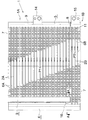
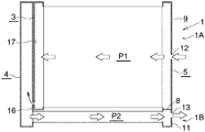
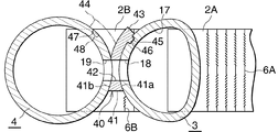
図1はこの発明によるコンデンサの第1の実施形態の全体構成を具体的に示し、図2は図1のコンデンサを模式的に示し、図3および図4は図1のコンデンサの要部の構成を示す。図2においては、個々の熱交換管の図示は省略されるとともに、コルゲートフィン、サイドプレート、冷媒入口部材および冷媒出口部材の図示も省略されている。 FIG. 1 specifically shows the overall configuration of the first embodiment of the capacitor according to the present invention, FIG. 2 schematically shows the capacitor of FIG. 1, and FIGS. 3 and 4 show the configuration of the main part of the capacitor of FIG. Indicates. In FIG. 2, illustration of individual heat exchange tubes is omitted, and illustration of corrugated fins, side plates, a refrigerant inlet member, and a refrigerant outlet member is also omitted.
図1および図2において、コンデンサ(1)には、凝縮部(1A)および過冷却部(1B)が、前者が上側に位置するように設けられており、幅方向を通風方向に向けるとともに長さ方向を左右方向に向けた状態で上下方向に間隔をおいて配置された複数のアルミニウム製扁平状熱交換管(2A)(2B)と、長さ方向を上下方向に向けて配置されるとともに熱交換管(2A)(2B)の左右両端部がろう付により接続された3つのアルミニウム製ヘッダタンク(3)(4)(5)と、隣り合う熱交換管(2A)(2B)どうしの間および上下両端の外側に配置されて熱交換管(2A)(2B)にろう付されたアルミニウム製コルゲートフィン(6A)(6B)と、上下両端のコルゲートフィン(6A)(6B)の外側に配置されてコルゲートフィン(6A)(6B)にろう付されたアルミニウム製サイドプレート(7)とを備えている。 1 and 2, the condenser (1) is provided with a condensing part (1A) and a supercooling part (1B) so that the former is located on the upper side. A plurality of aluminum flat heat exchange tubes (2A) (2B) arranged at intervals in the vertical direction with the vertical direction oriented in the horizontal direction, and the length direction thereof arranged in the vertical direction Three aluminum header tanks (3), (4) and (5), where the left and right ends of the heat exchange tubes (2A) and (2B) are connected by brazing, and the adjacent heat exchange tubes (2A and 2B) Aluminum corrugated fins (6A) and (6B) brazed to the heat exchange tubes (2A) and (2B), placed outside and between the upper and lower ends, and outside the corrugated fins (6A and 6B) at the upper and lower ends And an aluminum side plate (7) that is disposed and brazed to the corrugated fins (6A) and (6B).
コンデンサ(1)の凝縮部(1A)および過冷却部(1B)には、それぞれ上下に連続して並んだ複数の熱交換管(2A)(2B)からなる少なくとも1つ、ここでは1つの熱交換パス(P1)(P2)が設けられており、凝縮部(1A)に設けられた熱交換パス(P1)が冷媒凝縮パスとなり、過冷却部(1B)に設けられた熱交換パス(P2)が冷媒過冷却パスとなっている。そして、各熱交換パス(P1)(P2)を構成する全ての熱交換管(2A)(2B)の冷媒流れ方向が同一となっているとともに、隣り合う2つの熱交換パスの熱交換管(2A)(2B)の冷媒流れ方向が異なっている。ここで、凝縮部(1A)の熱交換パス(P1)を第1熱交換パスといい、過冷却部(1B)の熱交換パス(P2)を第2熱交換パスというものとする。 The condenser (1A) and the supercooling section (1B) of the condenser (1) have at least one heat exchange pipe (2A) (2B) arranged in a row in the vertical direction, here one heat. An exchange path (P1) (P2) is provided, the heat exchange path (P1) provided in the condensing part (1A) becomes a refrigerant condensing path, and the heat exchange path (P2 provided in the supercooling part (1B)) ) Is the refrigerant supercooling path. Then, the refrigerant flow directions of all heat exchange pipes (2A) (2B) constituting each heat exchange path (P1) (P2) are the same, and the heat exchange pipes of two adjacent heat exchange paths ( The refrigerant flow directions of 2A and (2B) are different. Here, the heat exchange path (P1) of the condensing part (1A) is referred to as a first heat exchange path, and the heat exchange path (P2) of the supercooling part (1B) is referred to as a second heat exchange path.
コンデンサ(1)の左端側には、凝縮部(1A)に設けられた第1熱交換パス(P1)の全熱交換管(2A)の左端部がろう付により接続された第1ヘッダタンク(3)と、過冷却部(1B)に設けられた第2熱交換パス(P2)の熱交換管(2B)の左端部がろう付により接続された第2ヘッダタンク(4)とが別個に設けられている。第2ヘッダタンク(4)の上端は第1ヘッダタンク(3)の下端よりも上方、ここでは第1ヘッダタンク(3)の上端とほぼ同一高さ位置にある。また、第2ヘッダタンク(4)の下端は第1ヘッダタンク(3)の下端よりも下方に位置しており、第2ヘッダタンク(4)における第1ヘッダタンク(3)よりも下方に位置する部分に、第2熱交換パス(P2)を構成する第2熱交換管(2B)がろう付により接続されている。第2ヘッダタンク(4)の内容積は、第2ヘッダタンク(4)内に流入した気液混相冷媒のうち液相主体混相冷媒が重力により第2ヘッダタンク(4)内の下部に溜まるとともに、気液混相冷媒のうちの気相成分が重力により第2ヘッダタンク(4)内の上部に溜まり、これにより気液を分離しうるような内容積となっている。したがって、第2ヘッダタンク(4)は、重力を利用して気液を分離しかつ液を溜める受液部としての機能を有している。 On the left end side of the condenser (1) is a first header tank (the left end of the total heat exchange pipe (2A) of the first heat exchange path (P1) provided in the condenser (1A) is connected by brazing. 3) separately from the second header tank (4) where the left end of the heat exchange pipe (2B) of the second heat exchange path (P2) provided in the supercooling section (1B) is connected by brazing. Is provided. The upper end of the second header tank (4) is above the lower end of the first header tank (3), here, at the same height as the upper end of the first header tank (3). The lower end of the second header tank (4) is located below the lower end of the first header tank (3), and is located below the first header tank (3) in the second header tank (4). The second heat exchange pipe (2B) constituting the second heat exchange path (P2) is connected to the portion to be brazed by brazing. The internal volume of the second header tank (4) is such that the liquid-phase mixed phase refrigerant out of the gas-liquid mixed phase refrigerant flowing into the second header tank (4) accumulates in the lower part of the second header tank (4) due to gravity. The gas phase component of the gas-liquid mixed phase refrigerant accumulates in the upper part of the second header tank (4) due to gravity, and thereby has an internal volume capable of separating the gas and liquid. Therefore, the second header tank (4) functions as a liquid receiving part that separates gas and liquid using gravity and stores the liquid.
ここで、第1ヘッダタンク(3)に接続された熱交換管(2A)を第1熱交換管といい、第2ヘッダタンク(4)に接続された熱交換管(2B)を第2熱交換管というものとする。また、隣り合う第1熱交換管(2A)どうしの間、上端の第1熱交換管(2A)と上側サイドプレート(7)との間、および下端の第1熱交換管(2A)と上端の第2熱交換管(2B)との間に配置されたコルゲートフィン(6A)を第1コルゲートフィンといい、隣り合う第2熱交換管(2B)どうしの間および下端の第2熱交換管(2B)と下側サイドプレート(7)との間に配置されたコルゲートフィン(6B)を第2コルゲートフィンというものとする。 Here, the heat exchange pipe (2A) connected to the first header tank (3) is called the first heat exchange pipe, and the heat exchange pipe (2B) connected to the second header tank (4) is the second heat. This is called an exchange tube. Also, between adjacent first heat exchange tubes (2A), between the first heat exchange tube (2A) at the upper end and the upper side plate (7), and between the first heat exchange tube (2A) at the lower end and the upper end The corrugated fin (6A) disposed between the second heat exchange pipe (2B) is called the first corrugated fin, and the second heat exchange pipe between the adjacent second heat exchange pipes (2B) and at the lower end. The corrugated fin (6B) disposed between (2B) and the lower side plate (7) is referred to as a second corrugated fin.
コンデンサ(1)の右端部側には、第1および第2熱交換パス(P1)(P2)を構成する全ての熱交換管(2A)(2B)の右端部が接続される第3ヘッダタンク(5)が配置されている。第3ヘッダタンク(5)の横断面形状は第1ヘッダタンク(3)と同一である。 Third header tank to which the right end of all heat exchange pipes (2A) (2B) constituting the first and second heat exchange paths (P1) (P2) is connected to the right end of the condenser (1) (5) is arranged. The cross-sectional shape of the third header tank (5) is the same as that of the first header tank (3).
第3ヘッダタンク(5)内は、第1熱交換パス(P1)と第2熱交換パス(P2)との間の高さ位置に設けられたアルミニウム製仕切板(8)により上側ヘッダ部(9)と下側ヘッダ部(11)とに区画されている。第3ヘッダタンク(5)の上側ヘッダ部(9)の高さ方向の中程に冷媒入口(12)が形成されるとともに、下側ヘッダ部(11)に冷媒出口(13)が形成されている。また、第3ヘッダタンク(5)に、冷媒入口(12)に通じる冷媒入口部材(14)および冷媒出口(13)に通じる冷媒出口部材(15)が接合されている。 Inside the third header tank (5), an upper header portion (8) is provided by an aluminum partition plate (8) provided at a height between the first heat exchange path (P1) and the second heat exchange path (P2). 9) and a lower header section (11). A refrigerant inlet (12) is formed in the middle of the height direction of the upper header portion (9) of the third header tank (5), and a refrigerant outlet (13) is formed in the lower header portion (11). Yes. In addition, a refrigerant inlet member (14) that communicates with the refrigerant inlet (12) and a refrigerant outlet member (15) that communicates with the refrigerant outlet (13) are joined to the third header tank (5).
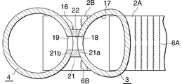
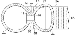
第1ヘッダタンク(3)に、凝縮部(1A)に設けられた第1熱交換パス(P1)の全第1熱交換管(2A)が接続されかつ連通部(16)を介して第2ヘッダタンク(4)に通じさせられた1つの連通区画(17)が設けられている。連通部(16)は、連通区画(17)に接続された全第1熱交換管(2A)のうち上端の第1熱交換管(2A)よりも下方の高さ位置、ここでは連通区画(17)の高さの中程よりも下側でかつ下端寄りの部分に設けられている。 All the first heat exchange pipes (2A) of the first heat exchange path (P1) provided in the condensing part (1A) are connected to the first header tank (3) and are connected to the second header via the communication part (16). One communication section (17) communicated with the header tank (4) is provided. The communication part (16) is located at a height lower than the first heat exchange pipe (2A) at the upper end of all the first heat exchange pipes (2A) connected to the communication section (17), here the communication section ( It is provided in the lower part of the height of 17) and closer to the lower end.
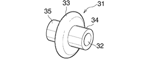
連通部(16)は、図3および図4に示すように、第1ヘッダタンク(3)の周壁に形成された貫通穴(18)と、第2ヘッダタンク(4)の周壁に形成された貫通穴(19)と、第1ヘッダタンク(3)と第2ヘッダタンク(4)との間に配置されて両ヘッダタンク(3)(4)にろう付され、かつ両ヘッダタンク(3)(4)の貫通穴(18)(19)どうしを通じさせる流路(22)を有するアルミニウム製連通部材(21)とを備えている。連通部材(21)の右側面には第1ヘッダタンク(3)の外周面に沿う第1凹円筒面(21a)が設けられ、同左側面には第2ヘッダタンク(4)の外周面に沿う第2凹円筒面(21b)が設けられており、流路(22)の両端は両凹円筒面(21a)(21b)に開口している。 As shown in FIGS. 3 and 4, the communication portion (16) is formed in the through hole (18) formed in the peripheral wall of the first header tank (3) and in the peripheral wall of the second header tank (4). It is placed between the through hole (19), the first header tank (3) and the second header tank (4), brazed to both header tanks (3) and (4), and both header tanks (3) And (4) an aluminum communication member (21) having a flow path (22) through which the through holes (18) and (19) pass. A first concave cylindrical surface (21a) is provided on the right side surface of the communication member (21) along the outer peripheral surface of the first header tank (3), and the left side surface is along the outer peripheral surface of the second header tank (4). A second concave cylindrical surface (21b) is provided, and both ends of the flow path (22) are open to the biconcave cylindrical surfaces (21a) and (21b).
コンデンサ(1)は、すべての部品を一括してろう付することにより製造される。 The capacitor (1) is manufactured by brazing all parts together.
コンデンサ(1)は、圧縮機、膨張弁(減圧器)およびエバポレータとともに冷凍サイクルを構成し、カーエアコンとして車両に搭載される。 The condenser (1) constitutes a refrigeration cycle together with a compressor, an expansion valve (decompressor) and an evaporator, and is mounted on a vehicle as a car air conditioner.
上述した構成のコンデンサ(1)において、圧縮機により圧縮された高温高圧の気相冷媒が、冷媒入口部材(14)および冷媒入口(12)を通って第3ヘッダタンク(5)の上側ヘッダ部(9)内に流入し、第1熱交換パス(P1)の第1熱交換管(2A)内を左方に流れる間に凝縮させられて第1ヘッダタンク(3)の連通区画(17)内に流入する。第1ヘッダタンク(3)の連通区画(17)内に流入した冷媒は、連通部(16)を構成する第1ヘッダタンク(3)の貫通穴(18)、連通部材(21)の流路(22)および第2ヘッダタンク(4)の貫通穴(19)を通って第2ヘッダタンク(4)内に流入する。 In the capacitor (1) having the above-described configuration, the high-temperature and high-pressure gas-phase refrigerant compressed by the compressor passes through the refrigerant inlet member (14) and the refrigerant inlet (12), and the upper header portion of the third header tank (5). (9) Inflowing into the first heat exchange pipe (2A) of the first heat exchange path (P1) and condensing while flowing to the left, the communication section (17) of the first header tank (3) Flows in. The refrigerant flowing into the communication section (17) of the first header tank (3) flows through the through hole (18) of the first header tank (3) and the communication member (21) constituting the communication section (16). It flows into the second header tank (4) through the through hole (19) of (22) and the second header tank (4).
第2ヘッダタンク(4)内に流入した冷媒は気液混相冷媒であり、当該気液混相冷媒のうち液相主体混相冷媒は重力により第2ヘッダタンク(4)内の下部に溜まり、第2熱交換パス(P2)の第2熱交換管(2B)内に入る。 The refrigerant flowing into the second header tank (4) is a gas-liquid mixed phase refrigerant. Among the gas-liquid mixed phase refrigerant, the liquid-phase main mixed phase refrigerant is accumulated in the lower part of the second header tank (4) due to gravity, and the second Enter the second heat exchange pipe (2B) of the heat exchange path (P2).
第2熱交換パス(P2)の第2熱交換管(2B)内に入った液相主体混相冷媒は第2熱交換管(2B)内を右方に流れる間に過冷却された後、第3ヘッダタンク(5)の下側ヘッダ部(11)内に入り、冷媒出口(13)および冷媒出口部材(15)を通って流出し、膨張弁を経て蒸発器に送られる。 The liquid-phase main mixed refrigerant entering the second heat exchange pipe (2B) of the second heat exchange path (P2) is supercooled while flowing rightward in the second heat exchange pipe (2B), It enters the lower header portion (11) of the three header tank (5), flows out through the refrigerant outlet (13) and the refrigerant outlet member (15), and is sent to the evaporator through the expansion valve.
一方、第2ヘッダタンク(4)内に流入した気液混相冷媒のうちの気相成分は、第2ヘッダタンク(4)内の上部に溜まる。 On the other hand, the gas phase component of the gas-liquid mixed phase refrigerant that has flowed into the second header tank (4) accumulates in the upper part of the second header tank (4).
図5〜図14は、第1ヘッダタンク(3)の連通区画(17)と第2ヘッダタンク(4)とを通じさせる連通部の変形例を示す。 FIGS. 5-14 shows the modification of the communication part made to let the communication division (17) and 2nd header tank (4) of a 1st header tank (3) pass.
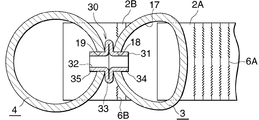
図5および図6に示す連通部(30)は、第1ヘッダタンク(3)の周壁に形成された貫通穴(18)と、第2ヘッダタンク(4)の周壁に形成された貫通穴(19)と、両ヘッダタンク(3)(4)の貫通穴(18)(19)どうしを通じさせる流路(32)を有し、かつ両ヘッダタンク(3)(4)にろう付されたアルミニウム製円筒状連通部材(31)とを備えている。連通部材(31)の長さ方向の中央部に両ヘッダタンク(3)(4)に位置する環状ビード(33)が形成されており、連通部材(31)における環状ビード(33)の右側部分に、第1ヘッダタンク(3)の貫通穴(18)内に挿入された第1挿入部(34)が設けられるとともに、同左側部分に、第2ヘッダタンク(4)の貫通穴(19)に挿入された第2挿入部(35)が設けられている。 The communication part (30) shown in FIG. 5 and FIG. 6 includes a through hole (18) formed in the peripheral wall of the first header tank (3) and a through hole formed in the peripheral wall of the second header tank (4). 19) and a flow path (32) through which the through holes (18) (19) of both header tanks (3) and (4) pass, and brazed to both header tanks (3) and (4) And a cylindrical communication member (31). An annular bead (33) positioned in both header tanks (3) and (4) is formed at the center in the length direction of the communicating member (31), and the right side portion of the annular bead (33) in the communicating member (31) In addition, a first insertion portion (34) inserted into the through hole (18) of the first header tank (3) is provided, and a through hole (19) of the second header tank (4) is provided on the left side portion. A second insertion part (35) inserted into the is provided.
図7および図8に示す連通部(40)は、第1ヘッダタンク(3)の周壁に形成された貫通穴(18)と、第2ヘッダタンク(4)の周壁に形成された貫通穴(19)と、第1ヘッダタンク(3)と第2ヘッダタンク(4)との間に配置されて両ヘッダタンク(3)(4)にろう付され、かつ両ヘッダタンク(3)(4)の貫通穴(18)(19)どうしを通じさせる流路(42)を有するアルミニウム製連通部材(41)とを備えている。連通部材(41)の右側面には第1ヘッダタンク(3)の外周面に沿う第1凹円筒面(41a)が設けられ、同左側面には第2ヘッダタンク(4)の外周面に沿う第2凹円筒面(41b)が設けられており、流路(42)の両端は両凹円筒面(41a)(41b)に開口している。
7 and 8 includes a through
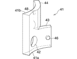
また、連通部材(41)の下半部には、通風方向のいずれか一方にのびて第1ヘッダタンク(3)の外周面に沿う第1延長部(43)が設けられて第1ヘッダタンク(3)にろう付されるとともに、同上半部には第1延長部(43)と同方向にのびて第2ヘッダタンク(4)の外周面に沿う第2延長部(44)が設けられ第2ヘッダタンク(4)にろう付されている。第1延長部(43)の右側面には第1ヘッダタンク(3)の外周面に形成された有底穴(45)に嵌め入れられる第1突起(46)が形成され、第2延長部(44)の左側面には第2ヘッダタンク(4)の外周面に形成された有底穴(47)に嵌め入れられる第2突起(48)が形成されている。 The lower half of the communication member (41) is provided with a first extension (43) extending along one of the ventilation directions along the outer peripheral surface of the first header tank (3). In addition to being brazed to (3), the upper half is provided with a second extension (44) extending in the same direction as the first extension (43) and along the outer peripheral surface of the second header tank (4). The second header tank (4) is brazed. A first protrusion (46) is formed on the right side surface of the first extension (43) and is fitted into a bottomed hole (45) formed on the outer peripheral surface of the first header tank (3). A second protrusion (48) is formed on the left side surface of (44) to be fitted into a bottomed hole (47) formed on the outer peripheral surface of the second header tank (4).
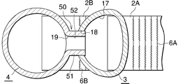
図9および図10に示す連通部(50)は、第1ヘッダタンク(3)の周壁に形成された貫通穴(18)と、第2ヘッダタンク(4)の周壁に形成された貫通穴(19)と、第2ヘッダタンク(4)の周壁における貫通穴(19)の周囲に外方突出状に一体形成され、かつ第1ヘッダタンク(3)の貫通穴(18)内に挿入されて第1ヘッダタンク(3)にろう付された筒状部(51)とを備えており、筒状部(51)内が両ヘッダタンク(3)(4)の貫通穴(18)(19)どうしを通じさせる流路(52)となっている。
9 and 10 includes a through
図11に示す連通部(55)は、第1ヘッダタンク(3)の周壁に形成された貫通穴(18)と、第2ヘッダタンク(4)の周壁に形成された貫通穴(19)と、第1ヘッダタンク(3)の周壁における貫通穴(18)の周囲に外方突出状に一体形成され、かつ第2ヘッダタンク(4)の貫通穴(19)内に挿入されて第2ヘッダタンク(4)にろう付された筒状部(56)とを備えており、筒状部(56)内が両ヘッダタンク(3)(4)の貫通穴(18)(19)どうしを通じさせる流路(57)となっている。 The communication part (55) shown in FIG. 11 includes a through hole (18) formed in the peripheral wall of the first header tank (3), and a through hole (19) formed in the peripheral wall of the second header tank (4). The first header tank (3) is integrally formed in an outward projecting manner around the through hole (18) in the peripheral wall of the first header tank (3), and is inserted into the through hole (19) of the second header tank (4). And a cylindrical part (56) brazed to the tank (4), and the inside of the cylindrical part (56) passes through the through holes (18) (19) of both header tanks (3) (4). A flow path (57) is formed.
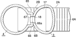
図12に示す連通部(60)は、第1ヘッダタンク(3)の周壁に形成された貫通穴(18)と、第2ヘッダタンク(4)の周壁に形成された貫通穴(19)と、第1ヘッダタンク(3)の周壁における貫通穴(18)の周囲に外方突出状に一体形成された第1筒状部(61)と、第2ヘッダタンク(4)の周壁における貫通穴(19)の周囲に外方突出状に一体形成され、かつ第1ヘッダタンク(3)の第1筒状部(61)の周囲に嵌め被せられて第1筒状部(61)にろう付された筒状部(62)とを備えており、両筒状部(61)(62)内が両ヘッダタンク(3)(4)の貫通穴(18)(19)どうしを通じさせる流路(63)(64)となっている。 The communication part (60) shown in FIG. 12 includes a through hole (18) formed in the peripheral wall of the first header tank (3), and a through hole (19) formed in the peripheral wall of the second header tank (4). A first tubular part (61) integrally formed in an outward projecting manner around a through hole (18) in the peripheral wall of the first header tank (3), and a through hole in the peripheral wall of the second header tank (4) It is integrally formed around the periphery of (19) so as to project outward, and is fitted around the first cylindrical portion (61) of the first header tank (3) to be brazed to the first cylindrical portion (61). A cylindrical passage (62), and a flow path (18) (19) through the through-holes (18) (19) of both header tanks (3) (4) inside the tubular portions (61) (62) ( 63) (64).
図13および図14に示す連通部(65)は、第1ヘッダタンク(3)の周壁に形成された貫通穴(18)と、第2ヘッダタンク(4)の周壁に形成されかつ第1ヘッダタンク(3)にろう付された外方膨出部(66)と、外方膨出部(66)の膨出頂壁に形成されかつ第1ヘッダタンク(3)の貫通穴(18)に通じる貫通穴(67)とを備えている。外方膨出部(66)の膨出頂壁の外面には、第1ヘッダタンク(3)の外周面に沿う凹円筒面(66a)が設けられている。 The communication part (65) shown in FIG. 13 and FIG. 14 is formed in the through hole (18) formed in the peripheral wall of the first header tank (3), and in the peripheral wall of the second header tank (4), and the first header. An outwardly bulging portion (66) brazed to the tank (3), a bulging top wall of the outwardly bulging portion (66), and a through hole (18) of the first header tank (3) And a through-hole (67) communicating therewith. A concave cylindrical surface (66a) along the outer peripheral surface of the first header tank (3) is provided on the outer surface of the bulging top wall of the outward bulging portion (66).
図15〜図18はこの発明によるコンデンサの他の実施形態を示す。なお、図15〜図18はコンデンサを模式的に示すものであり、個々の熱交換管の図示は省略されるとともに、コルゲートフィン、サイドプレート、冷媒入口部材および冷媒出口部材の図示も省略されている。 15 to 18 show another embodiment of the capacitor according to the present invention. 15 to 18 schematically show the condenser, and the illustration of the individual heat exchange tubes is omitted, and the illustration of the corrugated fins, the side plate, the refrigerant inlet member and the refrigerant outlet member is also omitted. Yes.
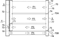
図15に示すコンデンサ(70)の場合、凝縮部(70A)および過冷却部(70B)が、前者が上側に位置するように設けられており、凝縮部(70A)に、上下に連続して並んだ複数の熱交換管(2A)からなる少なくとも1つ、ここでは3つの熱交換パス(P1)(P2)(P3)が上下に並んで設けられ、過冷却部(70B)に、上下に連続して並んだ複数の熱交換管(2B)からなる少なくとも1つ、ここでは1つの熱交換パス(P4)が設けられている。凝縮部(70A)に設けられた熱交換パス(P1)(P2)(P3)が冷媒凝縮パスとなり、過冷却部(70B)に設けられた熱交換パス(P4)が冷媒過冷却パスとなっている。そして、各熱交換パス(P1)(P2)(P3)(P4)を構成する全ての熱交換管(2A)(2B)の冷媒流れ方向が同一となっているとともに、隣り合う2つの熱交換パスの熱交換管(2A)(2B)の冷媒流れ方向が異なっている。なお、凝縮部(70A)に設けられた3つの熱交換パスを、上から順に第1〜第3熱交換パス(P1)(P2)(P3)といい、過冷却部(70B)に設けられた1つの熱交換パス(P4)を第4熱交換パス(P4)というものとする。第1〜第3熱交換パス(P1)(P2)(P3)の全熱交換管(2A)の左端部は第1ヘッダタンク(3)にろう付により接続され、第4熱交換パス(P4)の全熱交換管(2B)の左端部は第2ヘッダタンク(4)における第1ヘッダタンク(3)よりも下方に位置する部分にろう付により接続されている。ここで、第1ヘッダタンク(3)に接続された熱交換管(2A)を第1熱交換管といい、第2ヘッダタンク(4)に接続された熱交換管(2B)を第2熱交換管というものとする。 In the case of the condenser (70) shown in FIG. 15, the condensing part (70A) and the supercooling part (70B) are provided so that the former is located on the upper side, and is continuously connected to the condensing part (70A) vertically. At least one, consisting of a plurality of heat exchange tubes (2A) arranged side by side, here three heat exchange paths (P1), (P2) and (P3) are provided side by side in the vertical direction. At least one of a plurality of heat exchange tubes (2B) arranged in succession, here, one heat exchange path (P4) is provided. The heat exchange path (P1) (P2) (P3) provided in the condensing part (70A) serves as a refrigerant condensation path, and the heat exchange path (P4) provided in the supercooling part (70B) serves as a refrigerant subcooling path. ing. The refrigerant flow directions of all the heat exchange tubes (2A) (2B) constituting each heat exchange path (P1) (P2) (P3) (P4) are the same, and two adjacent heat exchanges The refrigerant flow directions of the heat exchange tubes (2A) and (2B) in the path are different. The three heat exchange paths provided in the condensing section (70A) are referred to as the first to third heat exchange paths (P1), (P2), and (P3) in order from the top, and are provided in the supercooling section (70B). One heat exchange path (P4) is referred to as a fourth heat exchange path (P4). The left end portion of the total heat exchange pipe (2A) of the first to third heat exchange paths (P1), (P2) and (P3) is connected to the first header tank (3) by brazing, and the fourth heat exchange path (P4 ) Of the total heat exchange pipe (2B) is connected to a portion of the second header tank (4) located below the first header tank (3) by brazing. Here, the heat exchange pipe (2A) connected to the first header tank (3) is called the first heat exchange pipe, and the heat exchange pipe (2B) connected to the second header tank (4) is the second heat. This is called an exchange tube.
コンデンサ(70)の左端側に配置され、かつ凝縮部(70A)に設けられた第1〜第3熱交換パス(P1)(P2)(P3)の全熱交換管(2A)の左端部がろう付により接続された第1ヘッダタンク(3)内は、第2熱交換パス(P2)と第3熱交換パス(P3)との間の高さ位置に設けられたアルミニウム製仕切板(71)により上側ヘッダ部(72)と下側ヘッダ部(73)とに区画されている。 The left end of the total heat exchange pipe (2A) of the first to third heat exchange paths (P1), (P2), and (P3) provided on the left end side of the condenser (70) and provided in the condenser (70A) The first header tank (3) connected by brazing has an aluminum partition plate (71) provided at a height between the second heat exchange path (P2) and the third heat exchange path (P3). ) Are divided into an upper header portion (72) and a lower header portion (73).
コンデンサ(70)の右端側に配置され、かつ第1〜第4熱交換パス(P1)(P2)(P3)(P4)を構成する全ての熱交換管(2A)(2B)がろう付により接続された第3ヘッダタンク(5)内は、第1熱交換パス(P1)と第2熱交換パス(P2)との間の高さ位置、および第3熱交換パス(P3)と第4熱交換パス(P4)との間の高さ位置にそれぞれ設けられたアルミニウム製仕切板(74)(75)により上側ヘッダ部(76)と中間ヘッダ部(77)と下側ヘッダ部(78)とに区画されている。第3ヘッダタンク(5)の上側ヘッダ部(76)に冷媒入口(12)が形成されるとともに、下側ヘッダ部(78)に冷媒出口(13)が形成されている。また、第3ヘッダタンク(5)に、冷媒入口(12)に通じる冷媒入口部材(図示略)および冷媒出口(13)に通じる冷媒出口部材(図示略)が接合されている。 All the heat exchange tubes (2A) (2B) which are arranged on the right end side of the condenser (70) and constitute the first to fourth heat exchange paths (P1, P2, P3, P4) are brazed. The connected third header tank (5) has a height position between the first heat exchange path (P1) and the second heat exchange path (P2), and the third heat exchange path (P3) and the fourth heat exchange path (P2). Aluminum partition plates (74) and (75) provided at a height between the heat exchange path (P4) and upper header (76), intermediate header (77) and lower header (78) It is divided into and. A refrigerant inlet (12) is formed in the upper header portion (76) of the third header tank (5), and a refrigerant outlet (13) is formed in the lower header portion (78). A refrigerant inlet member (not shown) that communicates with the refrigerant inlet (12) and a refrigerant outlet member (not shown) that communicates with the refrigerant outlet (13) are joined to the third header tank (5).
第1ヘッダタンク(3)の下側ヘッダ部(73)に、凝縮部(1A)に設けられた第1〜第3熱交換パス(P1)(P2)(P3)の冷媒流れ方向最下流側の第3熱交換パス(P3)の全第1熱交換管(2A)が接続されかつ連通部(16)を介して第2ヘッダタンク(4)に通じさせられた1つの連通区画(79)が設けられている。連通部(16)は、連通区画(79)に接続された第3熱交換パス(P3)の全第1熱交換管(2A)のうち上端の第1熱交換管(2A)よりも下方の高さ位置、ここでは連通区画(79)の高さの中程よりも下側でかつ下端寄りの部分に設けられている。 In the lower header portion (73) of the first header tank (3), the most downstream side in the refrigerant flow direction of the first to third heat exchange paths (P1) (P2) (P3) provided in the condensing portion (1A) One communication section (79) in which all the first heat exchange pipes (2A) of the third heat exchange path (P3) are connected and communicated with the second header tank (4) through the communication part (16). Is provided. The communication part (16) is located below the first heat exchange pipe (2A) at the upper end of all the first heat exchange pipes (2A) of the third heat exchange path (P3) connected to the communication section (79). It is provided at a position below the middle of the height position, here, the height of the communication section (79) and closer to the lower end.
その他の構成は図1〜図4に示すコンデンサと同様である。 Other configurations are the same as those of the capacitor shown in FIGS.
上述した構成のコンデンサ(70)において、圧縮機により圧縮された高温高圧の気相冷媒が、冷媒入口部材および冷媒入口(12)を通って第3ヘッダタンク(5)の上側ヘッダ部(76)内に流入し、第1熱交換パス(P1)の第1熱交換管(2A)内を左方に流れる間に凝縮させられて第1ヘッダタンク(3)の上側ヘッダ部(72)内に流入する。第1ヘッダタンク(3)の上側ヘッダ部(72)内に流入した冷媒は、第2熱交換パス(P2)の第1熱交換管(2A)内を右方に流れる間に凝縮させられて第3ヘッダタンク(5)の中間ヘッダ部(77)内に流入する。第3ヘッダタンク(5)の中間ヘッダ部(77)内に流入した冷媒は第3熱交換パス(P3)の第1熱交換管(2A)内を左方に流れる間に凝縮させられて第1ヘッダタンク(3)の下側ヘッダ部(73)の連通区画(79)内に流入する。第1ヘッダタンク(3)の下側ヘッダ部(73)の連通区画(79)内に流入した冷媒は、連通部(16)を構成する第1ヘッダタンク(3)の貫通穴(18)、連通部材(21)の流路(22)および第2ヘッダタンク(4)の貫通穴(19)を通って第2ヘッダタンク(4)内に流入する。 In the condenser (70) having the above-described configuration, the high-temperature and high-pressure gas-phase refrigerant compressed by the compressor passes through the refrigerant inlet member and the refrigerant inlet (12), and the upper header portion (76) of the third header tank (5). Into the upper header portion (72) of the first header tank (3) as it flows into the left and flows through the first heat exchange pipe (2A) of the first heat exchange path (P1) to the left. Inflow. The refrigerant flowing into the upper header portion (72) of the first header tank (3) is condensed while flowing rightward in the first heat exchange pipe (2A) of the second heat exchange path (P2). It flows into the intermediate header section (77) of the third header tank (5). The refrigerant flowing into the intermediate header section (77) of the third header tank (5) is condensed while flowing leftward in the first heat exchange pipe (2A) of the third heat exchange path (P3). 1 flows into the communication section (79) of the lower header section (73) of the header tank (3). The refrigerant that has flowed into the communication section (79) of the lower header section (73) of the first header tank (3) passes through the through holes (18) of the first header tank (3) constituting the communication section (16), It flows into the second header tank (4) through the flow path (22) of the communication member (21) and the through hole (19) of the second header tank (4).
第2ヘッダタンク(4)内に流入した冷媒は気液混相冷媒であり、当該気液混相冷媒のうち液相主体混相冷媒は重力により第2ヘッダタンク(4)内の下部に溜まり、第4熱交換パス(P4)の第2熱交換管(2B)内に入る。 The refrigerant flowing into the second header tank (4) is a gas-liquid mixed phase refrigerant. Among the gas-liquid mixed phase refrigerant, the liquid-phase main mixed phase refrigerant is accumulated in the lower part of the second header tank (4) due to gravity. The heat exchange path (P4) enters the second heat exchange pipe (2B).
第4熱交換パス(P4)の第2熱交換管(2B)内に入った液相主体混相冷媒は第2熱交換管(2B)内を右方に流れる間に過冷却された後、第3ヘッダタンク(5)の下側ヘッダ部(78)内に入り、冷媒出口(13)および冷媒出口部材を通って流出し、膨張弁を経て蒸発器に送られる。 The liquid phase main mixed refrigerant entering the second heat exchange pipe (2B) of the fourth heat exchange path (P4) is supercooled while flowing rightward in the second heat exchange pipe (2B), It enters the lower header section (78) of the three header tank (5), flows out through the refrigerant outlet (13) and the refrigerant outlet member, and is sent to the evaporator through the expansion valve.
一方、第2ヘッダタンク(4)内に流入した気液混相冷媒のうちの気相成分は、第2ヘッダタンク(4)内の上部に溜まる。 On the other hand, the gas phase component of the gas-liquid mixed phase refrigerant that has flowed into the second header tank (4) accumulates in the upper part of the second header tank (4).
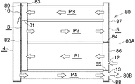
図16に示すコンデンサ(80)の場合、凝縮部(80A)および過冷却部(80B)が、前者が上側に位置するように設けられており、凝縮部(80A)に、上下に連続して並んだ複数の熱交換管(2A)からなる少なくとも1つ、ここでは3つの熱交換パス(P1)(P2)(P3)が上下に並んで設けられ、過冷却部(80B)に、上下に連続して並んだ複数の熱交換管(2B)からなる少なくとも1つ、ここでは1つの熱交換パス(P4)が設けられている。凝縮部(80A)に設けられた熱交換パス(P1)(P2)(P3)が冷媒凝縮パスとなり、過冷却部(80B)に設けられた熱交換パス(P4)が冷媒過冷却パスとなっている。そして、各熱交換パス(P1)(P2)(P3)(P4)を構成する全ての熱交換管(2A)(2B)の冷媒流れ方向が同一となっているとともに、隣り合う2つの熱交換パスの熱交換管(2A)(2B)の冷媒流れ方向が異なっている。なお、凝縮部(80A)に設けられた3つの熱交換パスを、下から順に第1〜第3熱交換パス(P1)(P2)(P3)といい、過冷却部(80B)に設けられた1つの熱交換パス(P4)を第4熱交換パス(P4)というものとする。第1〜第3熱交換パス(P1)(P2)(P3)の全熱交換管(2A)の左端部は第1ヘッダタンク(3)にろう付により接続され、第4熱交換パス(P4)の全熱交換管(2B)の左端部は第2ヘッダタンク(4)における第1ヘッダタンク(3)よりも下方に位置する部分にろう付により接続されている。ここで、第1ヘッダタンク(3)に接続された熱交換管(2A)を第1熱交換管といい、第2ヘッダタンク(4)に接続された熱交換管(2B)を第2熱交換管というものとする。 In the case of the condenser (80) shown in FIG. 16, the condensing part (80A) and the supercooling part (80B) are provided so that the former is located on the upper side, and the condensing part (80A) is continuously connected up and down. At least one, consisting of a plurality of heat exchange tubes (2A) arranged side by side, here three heat exchange paths (P1), (P2) and (P3) are provided side by side, and are arranged vertically in the supercooling section (80B). At least one of a plurality of heat exchange tubes (2B) arranged in succession, here, one heat exchange path (P4) is provided. The heat exchange path (P1) (P2) (P3) provided in the condensing part (80A) serves as a refrigerant condensing path, and the heat exchange path (P4) provided in the supercooling part (80B) serves as a refrigerant subcooling path. ing. The refrigerant flow directions of all the heat exchange tubes (2A) (2B) constituting each heat exchange path (P1) (P2) (P3) (P4) are the same, and two adjacent heat exchanges The refrigerant flow directions of the heat exchange tubes (2A) and (2B) in the path are different. The three heat exchange paths provided in the condensing section (80A) are referred to as the first to third heat exchange paths (P1), (P2), and (P3) in order from the bottom, and are provided in the supercooling section (80B). One heat exchange path (P4) is referred to as a fourth heat exchange path (P4). The left end portion of the total heat exchange pipe (2A) of the first to third heat exchange paths (P1), (P2) and (P3) is connected to the first header tank (3) by brazing, and the fourth heat exchange path (P4 ) Of the total heat exchange pipe (2B) is connected to a portion of the second header tank (4) located below the first header tank (3) by brazing. Here, the heat exchange pipe (2A) connected to the first header tank (3) is called the first heat exchange pipe, and the heat exchange pipe (2B) connected to the second header tank (4) is the second heat. This is called an exchange tube.
コンデンサ(80)の左端側に配置され、かつ凝縮部(80A)に設けられた第1〜第3熱交換パス(P1)(P2)(P3)の全熱交換管(2A)の左端部がろう付により接続された第1ヘッダタンク(3)内は、第2熱交換パス(P2)と第3熱交換パス(P3)との間の高さ位置に設けられたアルミニウム製仕切板(81)により下側ヘッダ部(82)と上側ヘッダ部(83)とに区画されている。 The left end of the total heat exchange pipe (2A) of the first to third heat exchange paths (P1), (P2), and (P3) provided on the left end of the condenser (80) and provided in the condenser (80A) The first header tank (3) connected by brazing has an aluminum partition plate (81) provided at a height between the second heat exchange path (P2) and the third heat exchange path (P3). ) Are divided into a lower header portion (82) and an upper header portion (83).
コンデンサ(80)の右端側に配置され、かつ第1〜第4熱交換パス(P1)(P2)(P3)(P4)を構成する全ての熱交換管(2A)(2B)がろう付により接続された第3ヘッダタンク(5)内は、第2熱交換パス(P2)と第3熱交換パス(P3)との間の高さ位置、および第3熱交換パス(P3)と第4熱交換パス(P4)との間の高さ位置にそれぞれ設けられたアルミニウム製仕切板(84)(85)により中間ヘッダ部(86)と上側ヘッダ部(87)と下側ヘッダ部(88)とに区画されている。第3ヘッダタンク(5)の中間ヘッダ部(86)に冷媒入口(86)が形成されるとともに、下側ヘッダ部(88)に冷媒出口(13)が形成されている。また、第3ヘッダタンク(5)に、冷媒入口(86)に通じる冷媒入口部材(図示略)および冷媒出口(13)に通じる冷媒出口部材(図示略)が接合されている。 All the heat exchange tubes (2A) (2B) that are arranged on the right end side of the condenser (80) and constitute the first to fourth heat exchange paths (P1, P2, P3, P4) are brazed. The connected third header tank (5) has a height position between the second heat exchange path (P2) and the third heat exchange path (P3), and the third heat exchange path (P3) and the fourth heat exchange path (P3). The intermediate header (86), upper header (87), and lower header (88) are provided by aluminum partition plates (84) (85) provided at a height between the heat exchange path (P4). It is divided into and. A refrigerant inlet (86) is formed in the intermediate header portion (86) of the third header tank (5), and a refrigerant outlet (13) is formed in the lower header portion (88). A refrigerant inlet member (not shown) that communicates with the refrigerant inlet (86) and a refrigerant outlet member (not shown) that communicates with the refrigerant outlet (13) are joined to the third header tank (5).
第1ヘッダタンク(3)の上側ヘッダ部(83)に、凝縮部(1A)に設けられた第1〜第3熱交換パス(P1)(P2)(P3)の冷媒流れ方向最下流側の第3熱交換パス(P3)の全第1熱交換管(2A)が接続されかつ連通部(16)を介して第2ヘッダタンク(4)に通じさせられた1つの連通区画(89)が設けられている。連通部(16)は、連通区画(89)に接続された第3熱交換パス(P3)の全第1熱交換管(2A)のうち上端の第1熱交換管(2A)よりも下方の高さ位置、ここでは連通区画(89)の高さの中程よりも下側でかつ下端寄りの部分に設けられている。 In the upper header part (83) of the first header tank (3), on the most downstream side in the refrigerant flow direction of the first to third heat exchange paths (P1) (P2) (P3) provided in the condensing part (1A). One communication section (89) connected to all the first heat exchange pipes (2A) of the third heat exchange path (P3) and connected to the second header tank (4) through the communication part (16) is provided. Is provided. The communication part (16) is located below the first heat exchange pipe (2A) at the upper end of all the first heat exchange pipes (2A) of the third heat exchange path (P3) connected to the communication section (89). It is provided at a position below the middle of the height position, here, the height of the communication section (89) and closer to the lower end.
その他の構成は図1〜図4に示すコンデンサと同様である。 Other configurations are the same as those of the capacitor shown in FIGS.
上述した構成のコンデンサ(80)において、圧縮機により圧縮された高温高圧の気相冷媒が、冷媒入口部材および冷媒入口(12)を通って第3ヘッダタンク(5)の中間ヘッダ部(86)内に流入し、第1熱交換パス(P1)の第1熱交換管(2A)内を左方に流れる間に凝縮させられて第1ヘッダタンク(3)の下側ヘッダ部(82)内に流入する。第1ヘッダタンク(3)の下側ヘッダ部(82)内に流入した冷媒は、第2熱交換パス(P2)の第1熱交換管(2A)内を右方に流れる間に凝縮させられて第3ヘッダタンク(5)の上側ヘッダ部(87)内に流入する。第3ヘッダタンク(5)の上側ヘッダ部(87)内に流入した冷媒は第3熱交換パス(P3)の第1熱交換管(2A)内を左方に流れる間に凝縮させられて第1ヘッダタンク(3)の上側ヘッダ部(83)の連通区画(89)内に流入する。第1ヘッダタンク(3)の上側ヘッダ部(83)の連通区画(89)内に流入した冷媒は、連通部(16)を構成する第1ヘッダタンク(3)の貫通穴(18)、連通部材(21)の流路(22)および第2ヘッダタンク(4)の貫通穴(19)を通って第2ヘッダタンク(4)内に流入する。 In the condenser (80) configured as described above, the high-temperature and high-pressure gas-phase refrigerant compressed by the compressor passes through the refrigerant inlet member and the refrigerant inlet (12), and the intermediate header portion (86) of the third header tank (5). Into the lower header section (82) of the first header tank (3) as it is condensed while it flows leftward in the first heat exchange pipe (2A) of the first heat exchange path (P1). Flow into. The refrigerant flowing into the lower header portion (82) of the first header tank (3) is condensed while flowing rightward in the first heat exchange pipe (2A) of the second heat exchange path (P2). Into the upper header portion (87) of the third header tank (5). The refrigerant flowing into the upper header portion (87) of the third header tank (5) is condensed while flowing leftward in the first heat exchange pipe (2A) of the third heat exchange path (P3). It flows into the communication section (89) of the upper header section (83) of the one header tank (3). The refrigerant flowing into the communication section (89) of the upper header section (83) of the first header tank (3) is communicated with the through hole (18) of the first header tank (3) constituting the communication section (16). It flows into the second header tank (4) through the channel (22) of the member (21) and the through hole (19) of the second header tank (4).
第2ヘッダタンク(4)内に流入した冷媒は気液混相冷媒であり、当該気液混相冷媒のうち液相主体混相冷媒は重力により第2ヘッダタンク(4)内の下部に溜まり、第4熱交換パス(P4)の第2熱交換管(2B)内に入る。 The refrigerant flowing into the second header tank (4) is a gas-liquid mixed phase refrigerant. Among the gas-liquid mixed phase refrigerant, the liquid-phase main mixed phase refrigerant is accumulated in the lower part of the second header tank (4) due to gravity. The heat exchange path (P4) enters the second heat exchange pipe (2B).
第4熱交換パス(P4)の第2熱交換管(2B)内に入った液相主体混相冷媒は第2熱交換管(2B)内を右方に流れる間に過冷却された後、第3ヘッダタンク(5)の下側ヘッダ部(88)内に入り、冷媒出口(13)および冷媒出口部材を通って流出し、膨張弁を経て蒸発器に送られる。 The liquid phase main mixed refrigerant entering the second heat exchange pipe (2B) of the fourth heat exchange path (P4) is supercooled while flowing rightward in the second heat exchange pipe (2B), It enters the lower header section (88) of the three header tank (5), flows out through the refrigerant outlet (13) and the refrigerant outlet member, and is sent to the evaporator through the expansion valve.
一方、第2ヘッダタンク(4)内に流入した気液混相冷媒のうちの気相成分は、第2ヘッダタンク(4)内の上部に溜まる。 On the other hand, the gas phase component of the gas-liquid mixed phase refrigerant that has flowed into the second header tank (4) accumulates in the upper part of the second header tank (4).
図17に示すコンデンサ(90)の場合、凝縮部(90A)および過冷却部(90B)が、前者が上側に位置するように設けられており、凝縮部(90A)に、上下に連続して並んだ複数の熱交換管(2A)からなる少なくとも1つ、ここでは2つの熱交換パス(P1)(P2)が上下に並んで設けられ、過冷却部(90B)に、上下に連続して並んだ複数の熱交換管(2B)からなる少なくとも1つ、ここでは1つの熱交換パス(P3)が設けられている。凝縮部(90A)に設けられた熱交換パス(P1)(P2)が冷媒凝縮パスとなり、過冷却部(90B)に設けられた熱交換パス(P3)が冷媒過冷却パスとなっている。そして、各熱交換パス(P1)(P2)(P3)を構成する全ての熱交換管(2A)(2B)の冷媒流れ方向が同一となっているとともに、隣り合う2つの熱交換パスの熱交換管(2A)(2B)の冷媒流れ方向が異なっている。なお、凝縮部(90A)に設けられた2つの熱交換パスを、上から順に第1〜第2熱交換パス(P1)(P2)といい、過冷却部(90B)に設けられた1つの熱交換パス(P3)を第3熱交換パス(P3)というものとする。第1〜第2熱交換パス(P1)(P2)の全熱交換管(2A)の左端部は第1ヘッダタンク(3)にろう付により接続され、第3熱交換パス(P3)の全熱交換管(2B)の左端部は第2ヘッダタンク(4)における第1ヘッダタンク(3)よりも下方に位置する部分にろう付により接続されている。ここで、第1ヘッダタンク(3)に接続された熱交換管(2A)を第1熱交換管といい、第2ヘッダタンク(4)に接続された熱交換管(2B)を第2熱交換管というものとする。そして、第1〜第2熱交換パス(P1)(P2)が冷媒凝縮パスとなり、第3熱交換パス(P3)が冷媒過冷却パスとなっている。 In the case of the condenser (90) shown in FIG. 17, the condensing part (90A) and the supercooling part (90B) are provided so that the former is located on the upper side, and is continuously connected to the condensing part (90A) vertically. At least one of the plurality of heat exchange tubes (2A) arranged side by side, in this case, two heat exchange paths (P1) (P2) are provided side by side in the vertical direction, and are continuously connected to the supercooling section (90B) in the vertical direction. At least one, that is, one heat exchange path (P3) composed of a plurality of heat exchange tubes (2B) arranged side by side is provided. The heat exchange path (P1) (P2) provided in the condensing part (90A) serves as a refrigerant condensing path, and the heat exchange path (P3) provided in the supercooling part (90B) serves as a refrigerant subcooling path. The refrigerant flow directions of all the heat exchange tubes (2A) (2B) constituting each heat exchange path (P1) (P2) (P3) are the same, and the heat of two adjacent heat exchange paths The refrigerant flow directions in the exchange pipes (2A) and (2B) are different. The two heat exchange paths provided in the condensing part (90A) are called the first to second heat exchange paths (P1) and (P2) in order from the top, and one heat exchange path provided in the supercooling part (90B). The heat exchange path (P3) is referred to as a third heat exchange path (P3). The left ends of the total heat exchange pipes (2A) of the first to second heat exchange paths (P1) and (P2) are connected to the first header tank (3) by brazing, and all the third heat exchange paths (P3) are connected. The left end of the heat exchange pipe (2B) is connected to a portion of the second header tank (4) located below the first header tank (3) by brazing. Here, the heat exchange pipe (2A) connected to the first header tank (3) is called the first heat exchange pipe, and the heat exchange pipe (2B) connected to the second header tank (4) is the second heat. This is called an exchange tube. The first to second heat exchange paths (P1) and (P2) serve as a refrigerant condensation path, and the third heat exchange path (P3) serves as a refrigerant subcooling path.
コンデンサ(90)の左端側に配置され、かつ凝縮部(90A)に設けられた第1〜第2熱交換パス(P1)(P2)の全熱交換管(2A)の左端部がろう付により接続された第1ヘッダタンク(3)内は、第1熱交換パス(P1)と第2熱交換パス(P2)との間の高さ位置に設けられたアルミニウム製仕切板(91)により上側ヘッダ部(92)と下側ヘッダ部(93)とに区画されている。第1ヘッダタンク(3)の上端は、コンデンサ(90)の左端側に配置され、かつ過冷却部(90B)に設けられた第3熱交換パス(P3)の全熱交換管(2A)の左端部がろう付により接続された第2ヘッダタンク(4)の上端よりも上方に位置しており、第1ヘッダタンク(3)の上側ヘッダ部(92)における第2ヘッダタンク(4)よりも上方に突出している部分に冷媒入口(12)が形成され、第1ヘッダタンク(3)に、冷媒入口(12)に通じる冷媒入口部材(図示略)が接合されている。 The left end of the total heat exchange pipe (2A) of the first to second heat exchange paths (P1) and (P2) disposed on the left end side of the condenser (90) and provided in the condenser (90A) is brazed. Inside the connected first header tank (3) is an upper side by an aluminum partition plate (91) provided at a height between the first heat exchange path (P1) and the second heat exchange path (P2). It is partitioned into a header part (92) and a lower header part (93). The upper end of the first header tank (3) is arranged on the left end side of the condenser (90) and is connected to the total heat exchange pipe (2A) of the third heat exchange path (P3) provided in the supercooling section (90B). From the second header tank (4) in the upper header portion (92) of the first header tank (3), the left end portion is located above the upper end of the second header tank (4) connected by brazing. Also, a refrigerant inlet (12) is formed in a portion protruding upward, and a refrigerant inlet member (not shown) communicating with the refrigerant inlet (12) is joined to the first header tank (3).
コンデンサ(90)の右端側に配置され、かつ第1〜第3熱交換パス(P1)(P2)(P3)を構成する全ての熱交換管(2A)(2B)がろう付により接続された第3ヘッダタンク(5)内は、第2熱交換パス(P2)と第3熱交換パス(P3)との間の高さ位置に設けられたアルミニウム製仕切板(94)により上側ヘッダ部(95)と下側ヘッダ部(96)とに区画されている。第3ヘッダタンク(5)の下側ヘッダ部(96)に冷媒出口(13)が形成され、第3ヘッダタンク(5)に、冷媒出口(13)に通じる冷媒出口部材(図示略)が接合されている。 All the heat exchange tubes (2A) (2B) which are arranged on the right end side of the condenser (90) and constitute the first to third heat exchange paths (P1, P2, P3) are connected by brazing. Inside the third header tank (5), an upper header portion (94) is provided by an aluminum partition plate (94) provided at a height between the second heat exchange path (P2) and the third heat exchange path (P3). 95) and a lower header section (96). A refrigerant outlet (13) is formed in the lower header portion (96) of the third header tank (5), and a refrigerant outlet member (not shown) leading to the refrigerant outlet (13) is joined to the third header tank (5). Has been.
第1ヘッダタンク(3)の下側ヘッダ部(93)に、凝縮部(1A)に設けられた第1〜第2熱交換パス(P1)(P2)の冷媒流れ方向最下流側の第2熱交換パス(P2)の全第1熱交換管(2A)が接続されかつ連通部(16)を介して第2ヘッダタンク(4)に通じさせられた1つの連通区画(97)が設けられている。連通部(16)は、連通区画(97)に接続された第2熱交換パス(P2)の全第1熱交換管(2A)のうち上端の第1熱交換管(2A)よりも下方の高さ位置、ここでは連通区画(97)の高さの中程よりも下側でかつ下端寄りの部分に設けられている。 In the lower header portion (93) of the first header tank (3), the second downstream side in the refrigerant flow direction of the first to second heat exchange paths (P1) (P2) provided in the condensing portion (1A). One communication section (97) connected to all the first heat exchange pipes (2A) of the heat exchange path (P2) and connected to the second header tank (4) through the communication section (16) is provided. ing. The communication part (16) is located below the first heat exchange pipe (2A) at the upper end of all the first heat exchange pipes (2A) of the second heat exchange path (P2) connected to the communication section (97). It is provided at a position below the middle of the height position, here, the height of the communication section (97) and closer to the lower end.
その他の構成は図1〜図4に示すコンデンサと同様である。 Other configurations are the same as those of the capacitor shown in FIGS.
上述した構成のコンデンサ(90)において、圧縮機により圧縮された高温高圧の気相冷媒が、冷媒入口部材および冷媒入口(12)を通って第1ヘッダタンク(3)の上側ヘッダ部(92)内に流入し、第1熱交換パス(P1)の第1熱交換管(2A)内を右方に流れる間に凝縮させられて第3ヘッダタンク(5)の上側ヘッダ部(95)内に流入する。第3ヘッダタンク(5)の上側ヘッダ部(95)内に流入した冷媒は第2熱交換パス(P2)の第1熱交換管(2A)内を左方に流れる間に凝縮させられて第1ヘッダタンク(3)の下側ヘッダ部(93)の連通区画(97)内に流入する。第1ヘッダタンク(3)の下側ヘッダ部(93)の連通区画(97)内に流入した冷媒は、連通部(16)を構成する第1ヘッダタンク(3)の貫通穴(18)、連通部材(21)の流路(22)および第2ヘッダタンク(4)の貫通穴(19)を通って第2ヘッダタンク(4)内に流入する。 In the condenser (90) having the above-described configuration, the high-temperature and high-pressure gas-phase refrigerant compressed by the compressor passes through the refrigerant inlet member and the refrigerant inlet (12), and the upper header portion (92) of the first header tank (3). Into the upper header section (95) of the third header tank (5) as it flows into the first heat exchange pipe (2A) of the first heat exchange path (P1) and flows to the right. Inflow. The refrigerant flowing into the upper header section (95) of the third header tank (5) is condensed while flowing leftward in the first heat exchange pipe (2A) of the second heat exchange path (P2). 1 flows into the communication section (97) of the lower header section (93) of the header tank (3). The refrigerant that has flowed into the communication section (97) of the lower header section (93) of the first header tank (3) passes through the through holes (18) of the first header tank (3) constituting the communication section (16), It flows into the second header tank (4) through the flow path (22) of the communication member (21) and the through hole (19) of the second header tank (4).
第2ヘッダタンク(4)内に流入した冷媒は気液混相冷媒であり、当該気液混相冷媒のうち液相主体混相冷媒は重力により第2ヘッダタンク(4)内の下部に溜まり、第3熱交換パス(P3)の第2熱交換管(2B)内に入る。 The refrigerant that has flowed into the second header tank (4) is a gas-liquid mixed phase refrigerant, and among the gas-liquid mixed phase refrigerant, the liquid-phase main mixed phase refrigerant accumulates in the lower part of the second header tank (4) due to gravity, and the third It enters the second heat exchange pipe (2B) of the heat exchange path (P3).
第3熱交換パス(P3)の第2熱交換管(2B)内に入った液相主体混相冷媒は第2熱交換管(2B)内を右方に流れる間に過冷却された後、第3ヘッダタンク(5)の下側ヘッダ部(96)内に入り、冷媒出口(13)および冷媒出口部材を通って流出し、膨張弁を経て蒸発器に送られる。 The liquid phase main mixed refrigerant entering the second heat exchange pipe (2B) of the third heat exchange path (P3) is supercooled while flowing rightward in the second heat exchange pipe (2B), It enters the lower header section (96) of the three header tank (5), flows out through the refrigerant outlet (13) and the refrigerant outlet member, and is sent to the evaporator through the expansion valve.
一方、第2ヘッダタンク(4)内に流入した気液混相冷媒のうちの気相成分は、第2ヘッダタンク(4)内の上部に溜まる。 On the other hand, the gas phase component of the gas-liquid mixed phase refrigerant that has flowed into the second header tank (4) accumulates in the upper part of the second header tank (4).
図18に示すコンデンサ(100)の場合、凝縮部(100A)および過冷却部(100B)が、前者が上側に位置するように設けられており、凝縮部(100A)に、上下に連続して並んだ複数の熱交換管(2A)からなる少なくとも1つ、ここでは2つの熱交換パス(P1)(P2)が上下に並んで設けられ、過冷却部(100B)に、上下に連続して並んだ複数の熱交換管(2B)からなる少なくとも1つ、ここでは1つの熱交換パス(P3)が設けられている。凝縮部(100A)に設けられた熱交換パス(P1)(P2)が冷媒凝縮パスとなり、過冷却部(100B)に設けられた熱交換パス(P3)が冷媒過冷却パスとなっている。そして、各熱交換パス(P1)(P2)(P3)を構成する全ての熱交換管(2A)(2B)の冷媒流れ方向が同一となっているとともに、隣り合う2つの熱交換パスの熱交換管(2A)(2B)の冷媒流れ方向が異なっている。なお、凝縮部(100A)に設けられた2つの熱交換パスを、下から順に第1〜第2熱交換パス(P1)(P2)といい、過冷却部(100B)に設けられた1つの熱交換パス(P3)を第3熱交換パス(P3)というものとする。第1〜第2熱交換パス(P1)(P2)の全熱交換管(2A)の左端部は第1ヘッダタンク(3)にろう付により接続され、第3熱交換パス(P3)の全熱交換管(2B)の左端部は第2ヘッダタンク(4)における第1ヘッダタンク(3)よりも下方に位置する部分にろう付により接続されている。ここで、第1ヘッダタンク(3)に接続された熱交換管(2A)を第1熱交換管といい、第2ヘッダタンク(4)に接続された熱交換管(2B)を第2熱交換管というものとする。そして、第1〜第2熱交換パス(P1)(P2)が冷媒凝縮パスとなり、第3熱交換パス(P3)が冷媒過冷却パスとなっている。 In the case of the condenser (100) shown in FIG. 18, the condensing part (100A) and the supercooling part (100B) are provided so that the former is located on the upper side, and the condensing part (100A) is continuously connected up and down. At least one, consisting of a plurality of heat exchange tubes (2A) arranged side by side, here two heat exchange paths (P1) (P2) are provided side by side in the vertical direction, and are continuously connected to the supercooling section (100B) in the vertical direction. At least one, that is, one heat exchange path (P3) composed of a plurality of heat exchange tubes (2B) arranged side by side is provided. The heat exchange path (P1) (P2) provided in the condensing unit (100A) is a refrigerant condensing path, and the heat exchanging path (P3) provided in the supercooling unit (100B) is a refrigerant subcooling path. The refrigerant flow directions of all the heat exchange tubes (2A) (2B) constituting each heat exchange path (P1) (P2) (P3) are the same, and the heat of two adjacent heat exchange paths The refrigerant flow directions in the exchange pipes (2A) and (2B) are different. The two heat exchange paths provided in the condensing unit (100A) are called first to second heat exchange paths (P1) and (P2) in order from the bottom, and one heat exchange path provided in the supercooling unit (100B). The heat exchange path (P3) is referred to as a third heat exchange path (P3). The left ends of the total heat exchange pipes (2A) of the first to second heat exchange paths (P1) and (P2) are connected to the first header tank (3) by brazing, and all the third heat exchange paths (P3) are connected. The left end of the heat exchange pipe (2B) is connected to a portion of the second header tank (4) located below the first header tank (3) by brazing. Here, the heat exchange pipe (2A) connected to the first header tank (3) is called the first heat exchange pipe, and the heat exchange pipe (2B) connected to the second header tank (4) is the second heat. This is called an exchange tube. The first to second heat exchange paths (P1) and (P2) serve as a refrigerant condensation path, and the third heat exchange path (P3) serves as a refrigerant subcooling path.
コンデンサ(100)の左端側に配置され、かつ凝縮部(100A)に設けられた第1〜第2熱交換パス(P1)(P2)の全熱交換管(2A)の左端部がろう付により接続された第1ヘッダタンク(3)内は、第1熱交換パス(P1)と第2熱交換パス(P2)との間の高さ位置に設けられたアルミニウム製仕切板(101)により下側ヘッダ部(102)と上側ヘッダ部(103)とに区画されている。第1ヘッダタンク(3)の下側ヘッダ部(102)に冷媒入口(12)が形成され、第1ヘッダタンク(3)に、冷媒入口(12)に通じる冷媒入口部材(図示略)が接合されている。 The left end of the total heat exchange pipe (2A) of the first to second heat exchange paths (P1) and (P2) located on the left end side of the condenser (100) and provided in the condenser (100A) is brazed. The connected first header tank (3) is lowered by an aluminum partition plate (101) provided at a height between the first heat exchange path (P1) and the second heat exchange path (P2). It is divided into a side header portion (102) and an upper header portion (103). A refrigerant inlet (12) is formed in the lower header portion (102) of the first header tank (3), and a refrigerant inlet member (not shown) leading to the refrigerant inlet (12) is joined to the first header tank (3). Has been.
コンデンサ(100)の右端側に配置され、かつ第1〜第3熱交換パス(P1)(P2)(P3)(P4)を構成する全ての熱交換管(2A)(2B)がろう付により接続された第3ヘッダタンク(5)内は、第1熱交換パス(P1)と第3熱交換パス(P3)との間の高さ位置に設けられたアルミニウム製仕切板(104)により上側ヘッダ部(105)と下側ヘッダ部(106)とに区画されている。第3ヘッダタンク(5)の下側ヘッダ部(106)に冷媒出口(13)が形成され、第3ヘッダタンク(5)に、冷媒出口(13)に通じる冷媒出口部材(図示略)が接合されている。 All the heat exchange pipes (2A) (2B) which are arranged on the right end side of the condenser (100) and constitute the first to third heat exchange paths (P1) (P2) (P3) (P4) are brazed. Inside the connected third header tank (5) is an upper side by an aluminum partition plate (104) provided at a height between the first heat exchange path (P1) and the third heat exchange path (P3). It is partitioned into a header part (105) and a lower header part (106). A refrigerant outlet (13) is formed in the lower header portion (106) of the third header tank (5), and a refrigerant outlet member (not shown) leading to the refrigerant outlet (13) is joined to the third header tank (5). Has been.
第1ヘッダタンク(3)の上側ヘッダ部(103)に、凝縮部(1A)に設けられた第1〜第2熱交換パス(P1)(P2)の冷媒流れ方向最下流側の第2熱交換パス(P2)の全第1熱交換管(2A)が接続されかつ連通部(16)を介して第2ヘッダタンク(4)に通じさせられた1つの連通区画(107)が設けられている。連通部(16)は、連通区画(107)に接続された第2熱交換パス(P2)の全第1熱交換管(2A)のうち上端の第1熱交換管(2A)よりも下方の高さ位置、ここでは連通区画(107)の高さの中程よりも下側でかつ下端寄りの部分に設けられている。 Second heat on the most downstream side in the refrigerant flow direction of the first to second heat exchange paths (P1) (P2) provided in the condensing unit (1A) is connected to the upper header unit (103) of the first header tank (3). There is provided one communication section (107) connected to all the first heat exchange pipes (2A) of the exchange path (P2) and connected to the second header tank (4) through the communication section (16). Yes. The communication part (16) is located below the first heat exchange pipe (2A) at the upper end of all the first heat exchange pipes (2A) of the second heat exchange path (P2) connected to the communication section (107). It is provided at a position below the middle of the height position, here, the height of the communication section (107) and closer to the lower end.
その他の構成は図1〜図4に示すコンデンサと同様である。 Other configurations are the same as those of the capacitor shown in FIGS.
上述した構成のコンデンサ(100)において、圧縮機により圧縮された高温高圧の気相冷媒が、冷媒入口部材および冷媒入口(12)を通って第1ヘッダタンク(3)の下側ヘッダ部(102)内に流入し、第1熱交換パス(P1)の第1熱交換管(2A)内を右方に流れる間に凝縮させられて第3ヘッダタンク(5)の上側ヘッダ部(105)内に流入する。第3ヘッダタンク(5)の上側ヘッダ部(105)内に流入した冷媒は第2熱交換パス(P2)の第1熱交換管(2A)内を左方に流れる間に凝縮させられて第1ヘッダタンク(3)の上側ヘッダ部(103)の連通区画(107)内に流入する。第1ヘッダタンク(3)の上側ヘッダ部(103)の連通区画(107)内に流入した冷媒は、連通部(16)を構成する第1ヘッダタンク(3)の貫通穴(18)、連通部材(21)の流路(22)および第2ヘッダタンク(4)の貫通穴(19)を通って第2ヘッダタンク(4)内に流入する。 In the condenser (100) having the above-described configuration, the high-temperature and high-pressure gas-phase refrigerant compressed by the compressor passes through the refrigerant inlet member and the refrigerant inlet (12), and the lower header portion (102 of the first header tank (3). ) And is condensed while flowing to the right in the first heat exchange pipe (2A) of the first heat exchange path (P1) in the upper header portion (105) of the third header tank (5). Flow into. The refrigerant flowing into the upper header portion (105) of the third header tank (5) is condensed while flowing leftward in the first heat exchange pipe (2A) of the second heat exchange path (P2). It flows into the communication section (107) of the upper header section (103) of one header tank (3). The refrigerant flowing into the communication section (107) of the upper header section (103) of the first header tank (3) is communicated with the through hole (18) of the first header tank (3) constituting the communication section (16). It flows into the second header tank (4) through the channel (22) of the member (21) and the through hole (19) of the second header tank (4).
第2ヘッダタンク(4)内に流入した冷媒は気液混相冷媒であり、当該気液混相冷媒のうち液相主体混相冷媒は重力により第2ヘッダタンク(4)内の下部に溜まり、第3熱交換パス(P3)の第2熱交換管(2B)内に入る。 The refrigerant that has flowed into the second header tank (4) is a gas-liquid mixed phase refrigerant, and among the gas-liquid mixed phase refrigerant, the liquid-phase main mixed phase refrigerant accumulates in the lower part of the second header tank (4) due to gravity, and the third It enters the second heat exchange pipe (2B) of the heat exchange path (P3).
第3熱交換パス(P3)の第2熱交換管(2B)内に入った液相主体混相冷媒は第2熱交換管(2B)内を右方に流れる間に過冷却された後、第3ヘッダタンク(5)の下側ヘッダ部(106)内に入り、冷媒出口(13)および冷媒出口部材を通って流出し、膨張弁を経て蒸発器に送られる。 The liquid phase main mixed refrigerant entering the second heat exchange pipe (2B) of the third heat exchange path (P3) is supercooled while flowing rightward in the second heat exchange pipe (2B), It enters the lower header section (106) of the three header tank (5), flows out through the refrigerant outlet (13) and the refrigerant outlet member, and is sent to the evaporator through the expansion valve.
一方、第2ヘッダタンク(4)内に流入した気液混相冷媒のうちの気相成分は、第2ヘッダタンク(4)内の上部に溜まる。 On the other hand, the gas phase component of the gas-liquid mixed phase refrigerant that has flowed into the second header tank (4) accumulates in the upper part of the second header tank (4).
図15〜図18に示すコンデンサ(70)(80)(90)(100)の場合も、連通部(16)に代えて、図5〜図14に示す連通部(30)(40)(50)(55)(60)(65)のうちのいずれかの連通部によって、第1ヘッダタンク(3)の連通区画(79)(89)(97)(107)と第2ヘッダタンク(4)とが通じさせられていてもよい。 In the case of the capacitors (70), (80), (90), and (100) shown in FIGS. 15 to 18, the communication portions (30), (40), and (50) shown in FIGS. ) (55) (60) (65), the communication section (79) (89) (97) (107) of the first header tank (3) and the second header tank (4) And may be communicated.
図1〜図4、図15〜図18に示すコンデンサ(1)(70)(80)(90)(100)において、第2ヘッダタンク(4)内に、乾燥剤やフィルタが配置されていてもよい。 In the capacitors (1), (70), (80), (90), and (100) shown in FIGS. 1 to 4 and 15 to 18, a desiccant and a filter are disposed in the second header tank (4). Also good.
この発明によるコンデンサは、自動車に搭載されるカーエアコンに好適に用いられる。 The capacitor | condenser by this invention is used suitably for the car air conditioner mounted in a motor vehicle.
(1)(70)(80)(90)(100):コンデンサ
(1A)(70A)(80A)(90A)(100A):凝縮部
(1B)(70B)(80B)(90B)(100B):過冷却部
(2A):第1熱交換管
(2B):第2熱交換管
(3):第1ヘッダタンク
(4):第2ヘッダタンク
(5):第3ヘッダタンク
(16)(30)(40)(50)(55)(60)(65):連通部
(17)(79)(89)(97)(107):連通区画
(P1):第1熱交換パス
(P2):第2熱交換パス
(P3):第3熱交換パス
(P4):第4熱交換パス
(1) (70) (80) (90) (100): Capacitor
(1A) (70A) (80A) (90A) (100A): Condensing part
(1B) (70B) (80B) (90B) (100B): Supercooling section
(2A): 1st heat exchange tube
(2B): Second heat exchange tube
(3): First header tank
(4): Second header tank
(5): Third header tank
(16) (30) (40) (50) (55) (60) (65): Communication part
(17) (79) (89) (97) (107): Communication section
(P1): First heat exchange path
(P2): Second heat exchange path
(P3): Third heat exchange path
(P4): Fourth heat exchange path
Claims (3)
左右いずれか一端部側に、凝縮部の全熱交換管が接続される第1ヘッダタンクと、過冷却部の全熱交換管が接続される第2ヘッダタンクとが設けられ、第1ヘッダタンクに、連通部を介して第2ヘッダタンクと通じかつ1つの熱交換パスを構成する全熱交換管が接続された1つの連通区画が設けられ、連通部が、連通区画に接続された全熱交換管のうち上端の熱交換管よりも下方の高さ位置に設けられ、第2ヘッダタンクが、第1ヘッダタンクよりも左右方向外側に配置され、第2ヘッダタンクの上端が第1ヘッダタンクの下端よりも上方に位置しているとともに、第2ヘッダタンクが気液を分離しかつ液を溜める機能を有しており、凝縮部の熱交換管を通過した全冷媒が第1ヘッダタンクの連通区画内に流入するとともに、連通部を通って第2ヘッダタンクに流入するようになされているコンデンサ。 A plurality of heat exchange tubes arranged in parallel with an interval in the vertical direction, with the condensing unit and the supercooling unit provided so that the former is located on the upper side, with the length direction facing the left and right direction; A header tank that is arranged with the length direction facing up and down and to which the left and right ends of the heat exchange pipe are connected, and a plurality of heat exchanges that are continuously arranged vertically in the condensing part and the supercooling part A condenser provided with at least one heat exchange path composed of a tube, and configured such that all of the refrigerant that has flowed through the heat exchange pipe of the condensing unit flows into the heat exchange pipe of the supercooling unit,
A first header tank to which the total heat exchange pipe of the condensing unit is connected and a second header tank to which the total heat exchange pipe of the supercooling unit is connected are provided on one of the left and right ends. In addition, there is provided one communication section connected to the second header tank via the communication section and connected to a total heat exchange pipe constituting one heat exchange path, and the communication section is connected to the communication section. The exchange pipe is provided at a lower position than the heat exchange pipe at the upper end, the second header tank is disposed on the outer side in the left-right direction with respect to the first header tank, and the upper end of the second header tank is the first header tank The second header tank has a function of separating gas and liquid and storing the liquid, and all the refrigerant that has passed through the heat exchange pipe of the condensing part is in the first header tank. Flows into the communication section and through the communication section 2 capacitor that is adapted to flow into the header tank.
Priority Applications (5)
| Application Number | Priority Date | Filing Date | Title |
|---|---|---|---|
| JP2011119903A JP2012247148A (en) | 2011-05-30 | 2011-05-30 | Condenser |
| US13/480,948 US20120305228A1 (en) | 2011-05-30 | 2012-05-25 | Condenser |
| DE102012208950A DE102012208950A1 (en) | 2011-05-30 | 2012-05-29 | capacitor |
| CN201220263820.6U CN202757354U (en) | 2011-05-30 | 2012-05-30 | Condenser |
| CN2012101811033A CN102809249A (en) | 2011-05-30 | 2012-05-30 | Condenser |
Applications Claiming Priority (1)
| Application Number | Priority Date | Filing Date | Title |
|---|---|---|---|
| JP2011119903A JP2012247148A (en) | 2011-05-30 | 2011-05-30 | Condenser |
Publications (2)
| Publication Number | Publication Date |
|---|---|
| JP2012247148A true JP2012247148A (en) | 2012-12-13 |
| JP2012247148A5 JP2012247148A5 (en) | 2014-07-03 |
Family
ID=47173564
Family Applications (1)
| Application Number | Title | Priority Date | Filing Date |
|---|---|---|---|
| JP2011119903A Pending JP2012247148A (en) | 2011-05-30 | 2011-05-30 | Condenser |
Country Status (4)
| Country | Link |
|---|---|
| US (1) | US20120305228A1 (en) |
| JP (1) | JP2012247148A (en) |
| CN (2) | CN102809249A (en) |
| DE (1) | DE102012208950A1 (en) |
Cited By (5)
| Publication number | Priority date | Publication date | Assignee | Title |
|---|---|---|---|---|
| JP2014145504A (en) * | 2013-01-28 | 2014-08-14 | T Rad Co Ltd | Condenser |
| JP2015132440A (en) * | 2014-01-15 | 2015-07-23 | 株式会社ケーヒン・サーマル・テクノロジー | capacitor |
| JP2015200478A (en) * | 2014-04-10 | 2015-11-12 | 株式会社ケーヒン・サーマル・テクノロジー | Condenser |
| JP2016057021A (en) * | 2014-09-11 | 2016-04-21 | 株式会社ケーヒン・サーマル・テクノロジー | Condenser |
| WO2019155752A1 (en) * | 2018-02-06 | 2019-08-15 | 株式会社デンソー | Condenser |
Families Citing this family (8)
| Publication number | Priority date | Publication date | Assignee | Title |
|---|---|---|---|---|
| JP2012247148A (en) * | 2011-05-30 | 2012-12-13 | Keihin Thermal Technology Corp | Condenser |
| DE102013211963A1 (en) * | 2013-06-24 | 2014-12-24 | Behr Gmbh & Co. Kg | capacitor assembly |
| US10801372B2 (en) | 2014-10-31 | 2020-10-13 | Modine Manufacturing Company | Cooling module and method for rejecting heat from a coupled engine system and rankine cycle waste heat recovery system |
| FR3028605B1 (en) * | 2014-11-14 | 2019-04-05 | Valeo Systemes Thermiques | FIXING DEVICE FOR HEAT EXCHANGER |
| EP3483546A1 (en) * | 2017-11-09 | 2019-05-15 | Valeo Autosystemy SP. Z.O.O. | A condenser |
| EP3620727A1 (en) * | 2018-09-06 | 2020-03-11 | Valeo Klimasysteme GmbH | Condenser with insert for an air conditioning system, in particular for a motor vehicle |
| CN110228348A (en) * | 2019-06-11 | 2019-09-13 | 上海加冷松芝汽车空调股份有限公司 | A kind of heat exchanger and automotive air-conditioning system |
| FR3126763B1 (en) * | 2021-09-03 | 2024-01-19 | Valeo Systemes Thermiques | HEAT EXCHANGER FOR REFRIGERANT FLUID LOOP |
Citations (5)
| Publication number | Priority date | Publication date | Assignee | Title |
|---|---|---|---|---|
| JP2001033121A (en) * | 1999-07-16 | 2001-02-09 | Denso Corp | Heat exchanger integrated with liquid receiver, and liquid receiver |
| US6694773B1 (en) * | 2003-01-29 | 2004-02-24 | Calsonickansei North America, Inc. | Condenser system with nondetachably coupled receiver |
| JP2004353936A (en) * | 2003-05-28 | 2004-12-16 | Denso Corp | Heat exchanger and liquid receiver-integrated condenser |
| JP2006266570A (en) * | 2005-03-23 | 2006-10-05 | Calsonic Kansei Corp | Vehicular cooling device |
| JP2009236404A (en) * | 2008-03-27 | 2009-10-15 | Denso Corp | Refrigeration cycle device |
Family Cites Families (8)
| Publication number | Priority date | Publication date | Assignee | Title |
|---|---|---|---|---|
| JPH07852Y2 (en) * | 1988-07-11 | 1995-01-11 | サンデン株式会社 | Condenser |
| JPH10122705A (en) * | 1996-10-14 | 1998-05-15 | Calsonic Corp | Condenser with liquid tank |
| FR2754887B1 (en) * | 1996-10-23 | 1998-12-31 | Valeo Thermique Moteur Sa | CONDENSER WITH REMOVABLE TANK FOR REFRIGERATION CIRCUIT, IN PARTICULAR OF MOTOR VEHICLE |
| JP2000227265A (en) * | 1999-02-03 | 2000-08-15 | Denso Corp | Refrigerant condenser integrated with liquid receiver |
| JP2000346568A (en) * | 1999-05-31 | 2000-12-15 | Mitsubishi Heavy Ind Ltd | Heat exchanger |
| DE10338527A1 (en) * | 2002-08-31 | 2004-03-11 | Behr Gmbh & Co. Kg | Coolant condenser for vehicle air conditioning unit has collector in form of one-piece tube connected to collection tube via overflow apertures |
| CN101978229B (en) * | 2008-10-20 | 2013-03-27 | 株式会社京滨冷暖科技 | Condenser |
| JP2012247148A (en) * | 2011-05-30 | 2012-12-13 | Keihin Thermal Technology Corp | Condenser |
-
2011
- 2011-05-30 JP JP2011119903A patent/JP2012247148A/en active Pending
-
2012
- 2012-05-25 US US13/480,948 patent/US20120305228A1/en not_active Abandoned
- 2012-05-29 DE DE102012208950A patent/DE102012208950A1/en active Pending
- 2012-05-30 CN CN2012101811033A patent/CN102809249A/en active Pending
- 2012-05-30 CN CN201220263820.6U patent/CN202757354U/en not_active Expired - Fee Related
Patent Citations (5)
| Publication number | Priority date | Publication date | Assignee | Title |
|---|---|---|---|---|
| JP2001033121A (en) * | 1999-07-16 | 2001-02-09 | Denso Corp | Heat exchanger integrated with liquid receiver, and liquid receiver |
| US6694773B1 (en) * | 2003-01-29 | 2004-02-24 | Calsonickansei North America, Inc. | Condenser system with nondetachably coupled receiver |
| JP2004353936A (en) * | 2003-05-28 | 2004-12-16 | Denso Corp | Heat exchanger and liquid receiver-integrated condenser |
| JP2006266570A (en) * | 2005-03-23 | 2006-10-05 | Calsonic Kansei Corp | Vehicular cooling device |
| JP2009236404A (en) * | 2008-03-27 | 2009-10-15 | Denso Corp | Refrigeration cycle device |
Cited By (5)
| Publication number | Priority date | Publication date | Assignee | Title |
|---|---|---|---|---|
| JP2014145504A (en) * | 2013-01-28 | 2014-08-14 | T Rad Co Ltd | Condenser |
| JP2015132440A (en) * | 2014-01-15 | 2015-07-23 | 株式会社ケーヒン・サーマル・テクノロジー | capacitor |
| JP2015200478A (en) * | 2014-04-10 | 2015-11-12 | 株式会社ケーヒン・サーマル・テクノロジー | Condenser |
| JP2016057021A (en) * | 2014-09-11 | 2016-04-21 | 株式会社ケーヒン・サーマル・テクノロジー | Condenser |
| WO2019155752A1 (en) * | 2018-02-06 | 2019-08-15 | 株式会社デンソー | Condenser |
Also Published As
| Publication number | Publication date |
|---|---|
| US20120305228A1 (en) | 2012-12-06 |
| CN202757354U (en) | 2013-02-27 |
| DE102012208950A1 (en) | 2012-12-06 |
| CN102809249A (en) | 2012-12-05 |
Similar Documents
| Publication | Publication Date | Title |
|---|---|---|
| JP2012247148A (en) | Condenser | |
| JP5501242B2 (en) | Capacitor | |
| JP5651431B2 (en) | Capacitor | |
| JP5907752B2 (en) | Heat exchanger | |
| JP5732258B2 (en) | Capacitor | |
| JP6035089B2 (en) | Heat exchanger | |
| JP5775715B2 (en) | Capacitor | |
| JP2013170732A5 (en) | ||
| JP2012154604A (en) | Condenser | |
| JP5412195B2 (en) | Heat exchanger | |
| US20170050489A1 (en) | Condenser | |
| JP5717474B2 (en) | Capacitor | |
| JP2011185562A (en) | Condenser | |
| JP2016217565A (en) | Condenser | |
| JP5622411B2 (en) | Capacitor | |
| JP2018200132A (en) | Condenser | |
| JP2013029257A (en) | Condenser | |
| JP5753694B2 (en) | Capacitor | |
| JP5484150B2 (en) | Capacitor | |
| JP4043577B2 (en) | Subcool system capacitor | |
| JP2019027685A (en) | Condenser | |
| JP5604140B2 (en) | Capacitor | |
| JP2015117878A (en) | Capacitor | |
| JP6322529B2 (en) | Capacitor | |
| JP5538045B2 (en) | Capacitor |
Legal Events
| Date | Code | Title | Description |
|---|---|---|---|
| A521 | Request for written amendment filed |
Free format text: JAPANESE INTERMEDIATE CODE: A523 Effective date: 20140520 |
|
| A621 | Written request for application examination |
Free format text: JAPANESE INTERMEDIATE CODE: A621 Effective date: 20140520 |
|
| A977 | Report on retrieval |
Free format text: JAPANESE INTERMEDIATE CODE: A971007 Effective date: 20150129 |
|
| A131 | Notification of reasons for refusal |
Free format text: JAPANESE INTERMEDIATE CODE: A131 Effective date: 20150203 |
|
| A521 | Request for written amendment filed |
Free format text: JAPANESE INTERMEDIATE CODE: A523 Effective date: 20150330 |
|
| A02 | Decision of refusal |
Free format text: JAPANESE INTERMEDIATE CODE: A02 Effective date: 20150630 |