WO2019155641A1 - ユーザ端末及び無線通信方法 - Google Patents
ユーザ端末及び無線通信方法 Download PDFInfo
- Publication number
- WO2019155641A1 WO2019155641A1 PCT/JP2018/004752 JP2018004752W WO2019155641A1 WO 2019155641 A1 WO2019155641 A1 WO 2019155641A1 JP 2018004752 W JP2018004752 W JP 2018004752W WO 2019155641 A1 WO2019155641 A1 WO 2019155641A1
- Authority
- WO
- WIPO (PCT)
- Prior art keywords
- transmission
- slot
- pusch
- pucch
- uplink
- Prior art date
Links
Images


Classifications
-
- H—ELECTRICITY
- H04—ELECTRIC COMMUNICATION TECHNIQUE
- H04W—WIRELESS COMMUNICATION NETWORKS
- H04W72/00—Local resource management
- H04W72/12—Wireless traffic scheduling
- H04W72/1263—Mapping of traffic onto schedule, e.g. scheduled allocation or multiplexing of flows
- H04W72/1268—Mapping of traffic onto schedule, e.g. scheduled allocation or multiplexing of flows of uplink data flows
-
- H—ELECTRICITY
- H04—ELECTRIC COMMUNICATION TECHNIQUE
- H04W—WIRELESS COMMUNICATION NETWORKS
- H04W72/00—Local resource management
- H04W72/20—Control channels or signalling for resource management
- H04W72/21—Control channels or signalling for resource management in the uplink direction of a wireless link, i.e. towards the network
-
- H—ELECTRICITY
- H04—ELECTRIC COMMUNICATION TECHNIQUE
- H04L—TRANSMISSION OF DIGITAL INFORMATION, e.g. TELEGRAPHIC COMMUNICATION
- H04L5/00—Arrangements affording multiple use of the transmission path
- H04L5/003—Arrangements for allocating sub-channels of the transmission path
- H04L5/0044—Arrangements for allocating sub-channels of the transmission path allocation of payload
-
- H—ELECTRICITY
- H04—ELECTRIC COMMUNICATION TECHNIQUE
- H04L—TRANSMISSION OF DIGITAL INFORMATION, e.g. TELEGRAPHIC COMMUNICATION
- H04L5/00—Arrangements affording multiple use of the transmission path
- H04L5/003—Arrangements for allocating sub-channels of the transmission path
- H04L5/0053—Allocation of signaling, i.e. of overhead other than pilot signals
-
- H—ELECTRICITY
- H04—ELECTRIC COMMUNICATION TECHNIQUE
- H04L—TRANSMISSION OF DIGITAL INFORMATION, e.g. TELEGRAPHIC COMMUNICATION
- H04L5/00—Arrangements affording multiple use of the transmission path
- H04L5/0091—Signaling for the administration of the divided path
- H04L5/0094—Indication of how sub-channels of the path are allocated
-
- H—ELECTRICITY
- H04—ELECTRIC COMMUNICATION TECHNIQUE
- H04L—TRANSMISSION OF DIGITAL INFORMATION, e.g. TELEGRAPHIC COMMUNICATION
- H04L5/00—Arrangements affording multiple use of the transmission path
- H04L5/14—Two-way operation using the same type of signal, i.e. duplex
- H04L5/1469—Two-way operation using the same type of signal, i.e. duplex using time-sharing
-
- H—ELECTRICITY
- H04—ELECTRIC COMMUNICATION TECHNIQUE
- H04W—WIRELESS COMMUNICATION NETWORKS
- H04W72/00—Local resource management
- H04W72/04—Wireless resource allocation
- H04W72/044—Wireless resource allocation based on the type of the allocated resource
- H04W72/0446—Resources in time domain, e.g. slots or frames
-
- H—ELECTRICITY
- H04—ELECTRIC COMMUNICATION TECHNIQUE
- H04L—TRANSMISSION OF DIGITAL INFORMATION, e.g. TELEGRAPHIC COMMUNICATION
- H04L5/00—Arrangements affording multiple use of the transmission path
- H04L5/0001—Arrangements for dividing the transmission path
- H04L5/0003—Two-dimensional division
- H04L5/0005—Time-frequency
- H04L5/0007—Time-frequency the frequencies being orthogonal, e.g. OFDM(A), DMT
-
- H—ELECTRICITY
- H04—ELECTRIC COMMUNICATION TECHNIQUE
- H04L—TRANSMISSION OF DIGITAL INFORMATION, e.g. TELEGRAPHIC COMMUNICATION
- H04L5/00—Arrangements affording multiple use of the transmission path
- H04L5/003—Arrangements for allocating sub-channels of the transmission path
- H04L5/0048—Allocation of pilot signals, i.e. of signals known to the receiver
- H04L5/0051—Allocation of pilot signals, i.e. of signals known to the receiver of dedicated pilots, i.e. pilots destined for a single user or terminal
-
- H—ELECTRICITY
- H04—ELECTRIC COMMUNICATION TECHNIQUE
- H04L—TRANSMISSION OF DIGITAL INFORMATION, e.g. TELEGRAPHIC COMMUNICATION
- H04L5/00—Arrangements affording multiple use of the transmission path
- H04L5/003—Arrangements for allocating sub-channels of the transmission path
- H04L5/0053—Allocation of signaling, i.e. of overhead other than pilot signals
- H04L5/0055—Physical resource allocation for ACK/NACK
-
- H—ELECTRICITY
- H04—ELECTRIC COMMUNICATION TECHNIQUE
- H04W—WIRELESS COMMUNICATION NETWORKS
- H04W72/00—Local resource management
- H04W72/20—Control channels or signalling for resource management
- H04W72/23—Control channels or signalling for resource management in the downlink direction of a wireless link, i.e. towards a terminal
Definitions
- the present invention relates to a user terminal and a wireless communication method in a next generation mobile communication system.
- LTE Long Term Evolution
- Non-Patent Document 1 LTE-A (LTE-Advanced), FRA (Future Radio Access), 4G, 5G, 5G + (plus), NR ( New RAT) and LTE Rel.14, 15 ⁇ ) are also being considered.
- a 1 ms subframe (also referred to as a transmission time interval (TTI), etc.) is used for downlink (DL) and / or uplink. Communication of a link (UL: Uplink) is performed.
- the subframe is a transmission time unit of one channel-encoded data packet, and is a processing unit such as scheduling, link adaptation, retransmission control (HARQ: Hybrid Automatic Repeat reQuest).
- the user terminal uses an uplink control channel (for example, PUCCH: Physical Uplink Control Channel) or an uplink shared channel (for example, PUSCH: Physical Uplink Shared Channel). And transmits uplink control information (UCI).
- uplink control channel for example, PUCCH: Physical Uplink Control Channel
- PUSCH Physical Uplink Shared Channel
- UCI uplink control information
- the configuration (format) of the uplink control channel is called a PUCCH format or the like.
- UCI is a scheduling request (SR: Scheduling Request), retransmission control information (HARQ-ACK: Hybrid Automatic Repeat reQuest-Acknowledge, ACK or NACK (Negative) for DL data (DL data channel (eg, PDSCH: Physical Downlink Shared Channel)) ACK)), and at least one of channel state information (CSI: Channel State Information).
- SR Scheduling Request
- HARQ-ACK Hybrid Automatic Repeat reQuest-Acknowledge
- ACK or NACK NACK (Negative) for DL data (DL data channel (eg, PDSCH: Physical Downlink Shared Channel))
- CSI Channel State Information
- data channels including DL data channels and / or UL data channels, also simply referred to as data, etc.
- control channels It is considered to flexibly control scheduling of a DL control channel and / or a UL control channel.
- UL data and UCI are transmitted using an uplink shared channel (PUSCH) ( UCI on PUSCH).
- PUSCH uplink shared channel
- future wireless communication systems it is conceivable to transmit UL data and UCI (A / N, etc.) using PUSCH as in the existing LTE system.
- the present invention has been made in view of the above points, and in future wireless communication systems, even when data channels and / or control channels are flexibly scheduled, uplink data and uplink using an uplink shared channel are provided.
- One of the purposes is to appropriately transmit control information (UCI on PUSCH).
- One aspect of the user terminal includes: a transmission unit that transmits uplink data and uplink control information in units of slots; a time division duplex (TDD) downlink (DL) / uplink (UL) allocation configuration; And a control unit that controls transmission of uplink control information via an uplink data channel based on a relationship between a plurality of slots specified for uplink data transmission and a plurality of slots specified for uplink control information transmission.
- TDD time division duplex
- DL downlink
- UL uplink
- uplink data and uplink control information transmission (UCI on PUSCH) using the uplink shared channel can be appropriately performed. it can.
- FIG. 1 is a diagram illustrating an example of multi-slot scheduling in PUSCH.
- FIG. 2 is a diagram for explaining PUCCH and PUSCH multislot scheduling rules in TDD.
- FIG. 3 is a diagram for explaining the execution of UCI on PUSCH when TDD and multi-slot scheduling are applied.
- 4A, 4B, and 4C are diagrams for explaining the arrangement configuration (slot configuration) of PUCCH and PUSCH in one slot.
- 5A, 5B, and 5C are diagrams for explaining the arrangement configuration (slot configuration) of PUCCH and PUSCH in one slot.
- FIG. 6 is a diagram for explaining UCI on PUSCH control in case 1-1 of the first mode.
- FIG. 1 is a diagram illustrating an example of multi-slot scheduling in PUSCH.
- FIG. 2 is a diagram for explaining PUCCH and PUSCH multislot scheduling rules in TDD.
- FIG. 3 is a diagram for explaining the execution of UCI on PUSCH when TDD
- FIG. 7 is a diagram for explaining UCI on PUSCH control in case 1-2 of the first mode.
- FIG. 8 is a diagram for explaining UCI on PUSCH control in case 1-2 of the first mode.
- FIG. 9 is a diagram for explaining UCI on PUSCH control in case 2-1 of the second mode.
- FIG. 10 is a diagram for explaining UCI on PUSCH control in case 2-1b of the second mode.
- FIG. 11 is a diagram for explaining UCI on PUSCH control in case 2-1c of the second mode.
- FIG. 12 is a diagram for explaining UCI on PUSCH control in case 2-2 of the second mode.
- FIG. 13 is a diagram for explaining UCI on PUSCH control in case 2-2b of the second mode.
- FIG. 14 is a diagram for explaining UCI on PUSCH control in case 2-2c of the second mode.
- FIG. 15 is a diagram for explaining overlap between the long PUCCH and the short PUSCH in the third mode.
- FIG. 16 is a diagram for explaining UCI on PUSCH control in the third mode.
- FIG. 17 is a diagram for explaining UCI on PUSCH control in the third mode. It is a figure which shows an example of schematic structure of the radio
- the time length is set as a scheduling unit of a data channel (including DL data channel and / or UL data channel, also simply referred to as data). It is contemplated to use a changeable time unit (eg, at least one of a slot, a minislot, and a predetermined number of symbols).
- a data channel including DL data channel and / or UL data channel, also simply referred to as data. It is contemplated to use a changeable time unit (eg, at least one of a slot, a minislot, and a predetermined number of symbols).
- the slot is a unit of time based on the neurology (for example, subcarrier interval and / or symbol length) applied by the user terminal.
- the number of symbols per slot may be determined according to the subcarrier interval. For example, when the subcarrier interval is 15 kHz or 30 kHz, the number of symbols per slot may be 7 or 14 symbols. On the other hand, when the subcarrier interval is 60 kHz or more, the number of symbols per slot may be 14 symbols.
- the subcarrier interval and the symbol length are inversely related. For this reason, if the symbols per slot are the same, the slot length becomes shorter as the subcarrier interval becomes higher (wider). On the other hand, the slot length becomes longer as the subcarrier interval becomes lower (narrower).
- the mini slot is a unit of time shorter than the slot.
- a mini-slot may be composed of a smaller number of symbols (for example, 1 to (slot length-1) symbols, for example, 2 or 3 symbols).
- the same neurology (eg, subcarrier spacing and / or symbol length) as the slot may be applied to the minislot within the slot, or a different neurology (eg, higher sub-slot than the slot).
- a carrier interval and / or a symbol length shorter than a slot) may be applied.
- the mini-slot may be composed of 2, 4, or 7 symbols, and may be PDSCH or PUSCH that can flexibly set the start symbol position.
- a PDSCH that is not a minislot may be a PDSCH having a start symbol position of the 0th to 3rd symbols in the slot and having a predetermined symbol length or more.
- a PUSCH that is not a mini-slot may be a PUSCH having a start symbol position of the 0th symbol in the slot and having a predetermined symbol length or longer.
- PDSCH and PUSCH that are not mini-slots may be called PDSCH / PUSCH mapping type A, and PDSCH and PUSCH that are mini-slots may be called PDSCH / PUSCH mapping type B.
- DMRSs may be inserted at different positions according to the PDSCH / PUSCH mapping type.
- which mapping type PDSCH / PUSCH is used may be set by higher layer signaling such as RRC, may be notified by DCI, or may be recognized by a combination of both. Also good.
- scheduling in a first time unit for example, slot unit
- scheduling in a second time unit for example, non-slot unit
- the non-slot unit may be a mini-slot unit or a symbol unit.
- a slot can be composed of, for example, 7 symbols or 14 symbols
- a minislot can be composed of 1 to (slot length-1) symbols.
- FIG. 1 shows a case where PUSCH is scheduled over K slots.
- PUCCH multi-slot scheduling is being studied for PUCCH. For example, when scheduling is performed in slot units, PUCCH is allocated to a plurality of slots.
- a configuration in which PUCCH is assigned to a plurality of slots is also referred to as PUCCH multi-slot scheduling or PUCCH multi-slot transmission.
- the configuration (format, PUCCH format (PF), etc.) for the uplink control channel (for example, PUCCH) used for UCI transmission is also used.
- PUCCH uplink control channel
- LTE Rel. 15 it is considered to support five types of PF0 to PF4.
- the name of PF shown below is only an illustration and a different name may be used.
- PF 0 and 1 are PFs used for transmission of UCI (for example, acknowledgment information (HARQ-ACK: Hybrid Automatic Repeat reQuest-Acknowledge, ACK or NACK)) of 2 bits or less (up to 2 bits). Since PF0 can be assigned to 1 or 2 symbols, it is also referred to as short PUCCH or sequence-based short PUCCH, etc. On the other hand, since PF1 can be assigned to 4-14 symbols, long PUCCH In PF1, the same resource block (physical resource) is obtained by time domain block spreading using at least one of cyclic shift (CS) and orthogonal spreading code (for example, OCC (Orthogonal Cover Code)). Multiple users within a block (PRB: Physical Resource Block)
- the terminal may be code division multiplexed (CDM).
- PF2-4 transmits more than 2 bits (more than 2 bits) UCI (for example, channel state information (CSI) (or CSI and HARQ-ACK and / or scheduling request (SR))) PF used. Since PF2 can be assigned to one or two symbols, it is also called a short PUCCH or the like. On the other hand, since PFs 3 and 4 can be assigned to 4-14 symbols, they are also called long PUCCHs. In PF4, a plurality of user terminals may be CDM using block spreading in the (frequency domain) before DFT.
- UCI for example, channel state information (CSI) (or CSI and HARQ-ACK and / or scheduling request (SR)
- PF2 can be assigned to one or two symbols, it is also called a short PUCCH or the like.
- PFs 3 and 4 can be assigned to 4-14 symbols, they are also called long PUCCHs.
- a plurality of user terminals may be CDM using block spreading in the (frequency domain) before DFT.
- Allocation of resources (for example, PUCCH resources) used for transmission of the uplink control channel is performed using higher layer signaling and / or downlink control information (DCI).
- the higher layer signaling is, for example, at least one of RRC (Radio Resource Control) signaling, system information (for example, RMSI: Remaining Minimum System Information, OSI: Other system information, MIB: Master Information Block, SIB: System Information Block).
- RRC Radio Resource Control
- system information for example, RMSI: Remaining Minimum System Information
- OSI Remaining Minimum System Information
- MIB Master Information Block
- SIB System Information Block
- broadcast information PBCH: Physical Broadcast Channel.
- UCI for example, A / N
- the base station specifies the UCI transmission timing / transmission period to the UE using downlink control information and / or higher layer signaling.
- the A / N feedback timing is flexibly set in a period after the downlink control information for notifying the transmission timing / transmission period of the A / N and / or the corresponding PDSCH.
- UCI transmission and UL data (UL-SCH) transmission occur at the same timing, UCI and UL data are multiplexed and transmitted on PUSCH (UCI). piggyback on PUSCH and UCI on PUSCH).
- TDD time division duplex
- TDD time division duplex
- uplink and downlink are time division multiplexed in the same frequency band.
- DL / UL allocation configuration can be set semi-statically by cell-specific (that is, a channel commonly received by UEs in the cell) or UE-specific higher layer signaling.
- the special subframe is divided into three parts: a downlink part (DwPTS: downlink pilot time slot), a guard interval (GP), and an uplink part (UpPTS: uplink pilot time slot).
- DwPTS downlink pilot time slot
- GP guard interval
- UpPTS uplink pilot time slot
- the “subframe” may be read as “slot”.
- TDD and multi-slot scheduling are applied to a wireless communication system, the following rules (regulations, conditions, and restrictions on operation in user terminals) are being studied.
- Kc is 4 or more
- slot # 0 the start slot.
- Values that can be set as Kc are 1, 2, 4, and 8.
- the value of Kc is set by RRC signaling.
- PUCCH transmission can be performed in the Kc slot section after slot # 0 (for example, when all Kc slots are UL slots)
- the user terminal starts PUCCH transmission symbols in slot # 0, the number of symbols, the PRB position, the PUCCH format, etc. Are transmitted in slot # 0.
- multi-slot transmission is performed in the Kc slot section using the same start symbol, number of symbols, PUCCH format, and the like as slot # 0.
- the PRB positions after slot # 1 can change depending on the presence of frequency hopping and its setting. That is, when frequency hopping between slots is set, PUCCH transmission is performed in slot # 1 using a PRB different from slot # 0.
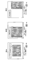
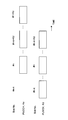
- uplink transmission is allocated to slots # 0, # 1, # 4, and # 5 in time-sequential slots # 0 to # 5. It has been.
- Slot # 2 is assigned downlink transmission.
- Slot # 3 is set as a special slot (the above-mentioned special subframe is replaced with a special slot).
- PUCCH transmission uplink transmission started from slot # 0 is continued until slot # 1. Thereafter, PUCCH transmission is not performed in slot # 2 to which downlink transmission is assigned. In slot # 3 corresponding to the special slot, when at least a part of the PUCCH transmission symbols set in the slot is a DL symbol in the slot, PUCCH transmission is not performed. Then, PUCCH transmission suspended in slot # 2 is resumed in slots # 4 and # 5.
- a slot to which uplink transmission is not assigned (a slot to which downlink transmission is assigned) or at least a part of a PUCCH transmission symbol set in the slot is UL in the slot. Even if the transmission of PUCCH is interrupted by being set as a symbol that cannot be transmitted (for example, DL symbol), the transmission of PUCCH is resumed in the slot where the subsequent PUCCH transmission is possible, and the specified Kc The PUCCH for the slot is transmitted.
- Kd is 3 or more
- the values that can be set as Kd are 1, 2, 4, and 8.
- the value of Kd is set by RRC signaling.
- the user terminal After slot # 0, when PUSCH transmission can be performed in the Kd slot section (for example, when all the Kd slots are UL slots), the user terminal starts PUSCH transmission symbols, number of symbols, PRB position, and transport block in slot # 0. The size, modulation scheme, DMRS pattern, etc. are determined, and transmission is performed in slot # 0. Further, multi-slot transmission is performed in the Kd slot section using the same start symbol, number of symbols, transport block size, modulation scheme, DMRS pattern, and the like as slot # 0.
- the PRB positions after slot # 1 can change depending on the presence of frequency hopping and its setting. That is, when frequency hopping between slots is set, PUSCH transmission is performed in slot # 1 using a PRB different from slot # 0.
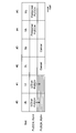
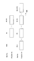
- the DL / UL allocation configuration is the same as in the case of the above-described PUCCH, and a description thereof will be omitted.
- PUSCH transmission In PUSCH transmission, uplink transmission started from slot # 0 is continued until slot # 1. Thereafter, since downlink transmission is assigned to slot # 2, uplink transmission cannot be performed, and continuous PUSCH transmission is interrupted. In PUSCH transmission, when continuous transmission is interrupted in this way, subsequent PUSCH transmission is not performed (cancelled) at that time. For example, PUSCH transmission is not resumed in slot # 4 to which uplink transmission is assigned.
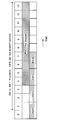
- PUCCH transmission and PUSCH transmission in TDD are different (ruled) in terms of user terminal operations. For this reason, some considerations occur when performing UCI on PUSCH in TDD (see FIG. 3).
- transmission may be interrupted by a slot to which uplink transmission is assigned (for example, slot # 2 in FIG. 3).
- the inventors of the present application control UCI on PUSCH based on at least one of the DL / UL allocation configuration and the relationship between consecutive slots of PUCCH and PUSCH specified by multi-slot scheduling. I was inspired by that. Thereby, even if TDD and multi-slot scheduling are applied, UCI on PUSCH can be appropriately performed.
- UCI is a scheduling request (SR: Scheduling Request), and acknowledgment information (HARQ-ACK: Hybrid Automatic Repeat reQuest-Acknowledge) for DL data channel (for example, PDSCH: Physical Downlink Shared Channel).
- SR Scheduling Request
- HARQ-ACK Hybrid Automatic Repeat reQuest-Acknowledge
- DL data channel for example, PDSCH: Physical Downlink Shared Channel.
- Channel state information (CSI: Channel State Information) including ACK, NACK (Negative ACK) or A / N), CQI: Channel Quality Indicator), rank information (RI: Rank Indicator), beam index information (BI: It may include at least one of a beam index and a buffer status report (BSR).
- BSR buffer status report
- each slot it is assumed that the assigned symbols of PUCCH and PUSCH partially or completely overlap.
- a plurality of arrangement relationships (case 1-6) shown in FIGS. 4 and 5 can be considered.
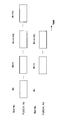
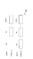
- Slot configuration 1 shows a configuration in which the PUCCH transmission period is included in the PUSCH transmission period. That is, the disclosure position of PUCCH (start position on the time axis (time domain)) is later than the start position of PUSCH, and the end position of PUCCH (end position on the time axis (time domain)) is greater than the end position of PUSCH. Too early.
- Slot configurations 2 and 3 show a configuration in which a PUCCH transmission period and a PUSCH transmission period partially overlap.
- the disclosure position of PUCCH is later than the start position of PUSCH, and the end position of PUCCH is later than the end position of PUSCH.
- slot configuration 3 the disclosure position of PUCCH is earlier than the start position of PUSCH, and the end position of PUCCH is earlier than the end position of PUSCH.
- Slot configuration 4 shows a configuration in which the PUCCH transmission period includes the PUSCH transmission period. That is, the PUCCH disclosure position is earlier than the PUSCH start position, and the PUCCH end position is later than the PUSCH end position.
- Slot configuration 5 shows a configuration in which the transmission period of PUCCH and the transmission period of PUSCH (including a reference signal) are set to be the same. That is, the PUCCH disclosure position and the PUSCH start position are equal, and the PUCCH end position and the PUSCH end position are equal.
- Slot configuration 6 shows a case where the transmission period of PUCCH and the transmission period of PUSCH (including a reference signal) are set so as not to overlap. That is, PUCCH and PUSCH are orthogonal.
- UCI on PUSCH may not be applied, and PUCCH and PUSCH may be controlled independently.
- PUCCH and PUSCH may be controlled independently.
- PUCCH and PUSCH may be controlled independently.
- PUCCH is transmitted in slots # 0, # 1, # 4, and # 5, and PUSCH is transmitted in slots # 0 and # 1.
- the number of slots (Kc) specified for PUCCH is equal to the number of slots (Kd) specified for PUSCH, and the start position (the first slot of the multi-slot) is Control in the case where PUCCH and PUSCH match will be described.
- the scheduling may be performed by the radio base station (gNB), and the following control may be performed by the user terminal.
- gNB radio base station
- Case 1-1 when all slots for Kc from the start position are allocated for uplink transmission in the DL / UL allocation configuration (the slots for Kc include slots other than uplink transmission). (If not). That is, the multi-slot PUCCH / PUSCH transmission is not interrupted by a slot to which uplink transmission is not assigned (a slot to which downlink transmission is assigned or a special slot). In such a case, UCI on PUSCH is performed in all slots for Kc. Specifically, as shown in FIG. 6, UCI on PUSCH is performed in slots # 0 to # 3.
- UCI mapping pattern and UL data rate matching and puncture control in UCI on PUSCH may be common to all slots constituting the multi-slot.
- case 1-2 a case will be described in which there are slots (or special slots) to which downlink transmission is allocated in the DL / UL allocation configuration for Kc slots from the start position. That is, multi-slot PUCCH / PUSCH transmission is interrupted by a slot (or special slot) to which downlink transmission is assigned. In such a case, the following two controls (options) can be considered.
- the rules for PUSCH multi-slot scheduling are applied to PUCCH multi-slot scheduling.
- PUSCH multi-slot scheduling when PUSCH transmission is interrupted by a slot to which uplink transmission is not assigned (a slot to which downlink transmission is assigned or a special slot), the subsequent PUSCH transmission is canceled. .
- PUCCH multi-slot scheduling Such rules also apply to PUCCH multi-slot scheduling. For this reason, when PUCCH transmission is interrupted by a slot to which uplink transmission is not assigned (a slot to which downlink transmission is assigned or a special slot), subsequent PUCCH transmission is canceled. On the other hand, UCI on PUSCH is performed in a slot before the PUSCH transmission is interrupted and in which the PUSCH and the PUCCH are scheduled simultaneously.
- UCI on PUSCH is performed in slots # 0 and # 1.
- PUCCH transmission is not performed even in slots # 4 and # 5 to which uplink transmission is allocated after interruption of PUCCH / PUSCH transmission.
- slots # 4 and # 5 PUSCH is not transmitted.
- the UE can appropriately transmit the UCI that has been transferred (piggybacked) from PUCCH to PUSCH by UCI on PUSCH, and PUCCH is transmitted unnecessarily after slot # 4. Can be prevented.
- UCI on PUSCH is performed in slots # 0 and # 1.
- PUSCH transmission is not performed in slots # 4 and # 5 to which uplink transmission is allocated after PUCCH / PUSCH transmission is interrupted.
- PUCCH transmission is performed in slots # 4 and # 5. In this way, the number of UCI transmission slots can be ensured regardless of whether UCI on PUSCH is applied, and UCI quality can be improved.
- transmission of uplink data and uplink control information (UCI on PUSCH) using the uplink shared channel is performed even when the data channel and / or the control channel are flexibly scheduled. Can be done appropriately.
- UCI on PUSCH can be appropriately performed even when time division duplex (TDD) and multi-slot scheduling are applied.
- the scheduling may be performed by the radio base station (gNB), and the following control may be performed by the user terminal.
- gNB radio base station
- PUCCH / PUSCH can be transmitted in all slots to which multi-slot PUCCH / PUSCH is assigned. For example, even when the DL / UL allocation configuration is set, if all slots to which multi-slot PUCCH / PUSCH are allocated are uplink slots (the designated multi-slot is a slot other than uplink transmission). Etc.). That is, multi-slot PUCCH / PUSCH transmission is not interrupted by the DL / UL allocation configuration.
- Case 2-1 is further classified. In this case, it is assumed that the end slots of PUCCH and PUSCH coincide (see FIG. 9). In such case 2-1a, the following control (option) can be considered.
- This option cancels (drops) the transmission started first among the PUCCH transmission and the PUSCH transmission, and only the transmission started later is performed.
- PUCCH transmission is canceled and only PUSCH transmission is performed.
- the transmission started first is canceled as much as possible or the transmission data is dropped at the user terminal. By doing so, it becomes possible to control new scheduling information with priority over old scheduling information in time, so that a low-delay service can be appropriately realized.
- Case 2-1 is further classified.
- the start position (start slot) of the scheduled PUCCH multislot is ahead of the start position of the PUSCH as in the previous case 2-1 a, but the end of the PUCCH Assume that the slot is earlier than the end slot of PUSCH (see FIG. 10).
- the following control (option) can be considered.
- UCI on PUSCH is performed in a slot where PUCCH and PUSCH overlap.
- non-overlapping slots that is, slots for which only PUCCH transmission is designated and slots for which only PUSCH transmission is designated, respective transmissions are performed.
- UCI on PUSCH is performed in all slots. For slots where PUCCH and PUSCH do not overlap, UCI or uplink data of the overlapping slot is copied and UCI on PUSCH is performed. In this way, UCI on PUSCH can be applied similarly between slots for multi-slot PUSCH (that is, since different mapping is not applied for each slot), reducing the terminal processing burden. it can. In addition, since the number of UCI transmissions can be increased, it is easy to ensure UCI quality.
- transmission is started only for transmission that has been started first among PUCCH transmission and PUSCH transmission, and transmission that is started later is canceled or transmission is performed only in non-overlapping slots. Specifically, only PUCCH transmission is performed, and PUSCH transmission is canceled. Alternatively, only PUCCH transmission is performed in a slot in which only PUCCH is specified, and a slot in which PUCCH and PUSCH are specified in duplicate, and only PUSCH transmission is performed in a slot in which only PUSCH is specified. Done. In this way, an opportunity to transmit both UCI and UL data can be provided. Moreover, since UCI on PUSCH control is not performed, the terminal processing burden can be reduced.
- Option 2-1b-4 In this option, only PUCCH transmission and PUSCH transmission are performed only for transmissions that are started later, and transmission that is started first is canceled or transmitted only in non-overlapping slots. Specifically, only PUSCH transmission is performed, and PUCCH transmission is canceled. Alternatively, only the PUSCH transmission is performed in the slot in which only the PUSCH is specified and the slot in which the PUCCH and the PUSCH are specified in duplicate, and only the PUCCH transmission is performed in the slot in which only the PUCCH is specified. Done. By doing so, it becomes possible to control new scheduling information with priority over old scheduling information in time, so that a low-delay service can be appropriately realized.
- Case 2-1 is further classified.
- the start position (start slot) of the scheduled PUCCH multi-slot is ahead of the start position of the PUSCH, as in the previous cases 2-1a and 2-1b.
- the PUSCH end slot is earlier than the PUCCH end slot (see FIG. 11).
- the following control (option) can be considered.
- transmission is started only for transmission that has been started first among PUCCH transmission and PUSCH transmission, and transmission that is started later is canceled or transmission is performed only in non-overlapping slots. Specifically, only PUCCH transmission is performed, and PUSCH transmission is canceled. Alternatively, only PUCCH transmission is performed in a slot in which only PUCCH is specified, and a slot in which PUCCH and PUSCH are specified in duplicate, and only PUSCH transmission is performed in a slot in which only PUSCH is specified. Done. In this way, the user terminal does not need to consider later transmission, and the terminal processing burden can be reduced.
- Case 2-2 In this case, all the slots are all allocated for uplink transmission in the DL / UL allocation configuration (when the designated multi-slot does not include any slot other than uplink transmission). This is the same as Case 2-1. That is, the multi-slot PUCCH / PUSCH transmission is not interrupted by a slot to which uplink transmission is not assigned (a slot to which downlink transmission is assigned or a special slot).
- Case 2-2 is further classified. In this case, it is assumed that the end slots of PUCCH and PUSCH coincide (see FIG. 12). In such case 2-2a, the following control (option) can be considered.
- This option cancels (drops) the transmission started first among the PUCCH transmission and the PUSCH transmission, and only the transmission started later is performed.
- PUSCH transmission is canceled and only PUCCH transmission is performed. Note that the transmission started first is canceled as much as possible or the transmission data is dropped at the user terminal. By doing so, it becomes possible to control new scheduling information with priority over old scheduling information in time, so that a low-delay service can be appropriately realized.
- Case 2-2 is further classified.
- the start position (start slot) of the scheduled PUSCH multi-slot is earlier than the start position of the PUCCH, as in the case 2-2a, but the end of the PUSCH. Assume that the slot is earlier than the end slot of PUCCH (see FIG. 13).
- the following control (option) can be considered.
- UCI on PUSCH is performed from the first overlapping slot to the last slot in which PUSCH is specified.
- UCI or UL data of the overlapping slot is copied and UCI on PUSCH is performed.
- UCI on PUSCH can be applied similarly between slots for multi-slot PUSCH (that is, since different mapping is not applied for each slot), reducing the terminal processing burden. it can.
- the number of UCI transmissions can be increased, it is easy to ensure UCI quality.
- transmission is started only for transmission that has been started first among PUCCH transmission and PUSCH transmission, and transmission that is started later is canceled or transmission is performed only in non-overlapping slots. Specifically, only PUSCH transmission is performed, and PUCCH transmission is canceled. Alternatively, only the PUSCH transmission is performed in the slot in which only the PUSCH is specified and the slot in which the PUCCH and the PUSCH are specified in duplicate, and only the PUCCH transmission is performed in the slot in which only the PUCCH is specified. Done. In this way, the number of transmission slots for UCI and UL data can be maintained while reducing the terminal processing burden.
- Option 2-2b-4 In this option, only PUCCH transmission and PUSCH transmission are performed only for transmissions that are started later, and transmission that is started first is canceled or transmitted only in non-overlapping slots. Specifically, only PUCCH transmission is performed, and PUSCH transmission is canceled. Alternatively, only PUCCH transmission is performed in a slot in which only PUCCH is specified, and a slot in which PUCCH and PUSCH are specified in duplicate, and only PUSCH transmission is performed in a slot in which only PUSCH is specified. Done. By doing so, it becomes possible to control new scheduling information with priority over old scheduling information in time, so that a low-delay service can be appropriately realized.
- Case 2-2 is further classified.
- the start position (start slot) of the scheduled PUCCH multislot is ahead of the start position of the PUSCH, as in the previous cases 2-2a and 2-2b.
- the PUSCH end slot is earlier than the PUCCH end slot (see FIG. 14).
- the following control (option) can be considered.
- transmission is started only for transmission that has been started first among PUCCH transmission and PUSCH transmission, and transmission that is started later is canceled or transmission is performed only in non-overlapping slots. Specifically, only PUCCH transmission is performed, and PUSCH transmission is canceled. Alternatively, only PUCCH transmission is performed in a slot in which only PUCCH is specified, and a slot in which PUCCH and PUSCH are specified in duplicate, and only PUSCH transmission is performed in a slot in which only PUSCH is specified. Done. By doing so, it is possible to transmit both UCI and UL data in at least one slot while reducing the burden on the terminal processing.
- the rules for PUSCH multi-slot scheduling are applied to PUCCH multi-slot scheduling.
- PUSCH multi-slot scheduling when PUSCH transmission is interrupted by a slot to which uplink transmission is not assigned (a slot to which downlink transmission is assigned or a special slot), the subsequent PUSCH transmission is canceled. .
- PUCCH multi-slot scheduling Such rules also apply to PUCCH multi-slot scheduling. For this reason, when PUCCH transmission is interrupted by a slot to which uplink transmission is not assigned (a slot to which downlink transmission is assigned or a special slot), subsequent PUCCH transmission is canceled. On the other hand, UCI on PUSCH is performed in a slot before the PUSCH transmission is interrupted and in which the PUSCH and the PUCCH are scheduled simultaneously.
- the options 2-3a and 2-3b can be realized by combining the options 1-2a and 1-2b in the first embodiment described above.
- UCI on PUSCH can be appropriately performed even when applying time division duplex (TDD) and multi-slot scheduling.
- TDD time division duplex
- FIG. 15 shows the configuration of one slot.
- HARQ-ACK may perform puncturing or rate matching. Also, the HARQ-ACK mapped to the first overlapping minislot may be repeated in subsequent minislot transmissions. Further, mapping may be performed over overlapping mini-slots or may be distributed and mapped.
- FIG. 17 collectively shows that UCI is UCI-on-PUSCH.
- the HARQ-ACK mapping performed in the first minislot is performed in the same manner in the next slot. In this way, terminal processing can be unified between the two minislots, and the processing burden can be reduced.
- the resource amount for mapping the HARQ-ACK is smaller than the resource amount of the first minislot, it is mapped only to the first minislot. Otherwise, map to the resource in the first minislot and map the deficit to the next minislot. In this way, an appropriate resource amount can be allocated to HARQ-ACK.
- UCI on PUSCH is appropriate even when long PUCCH and short PUSCH are used when applying time division duplex (TDD) and multi-slot scheduling. Can be done.
- TDD time division duplex
- wireless communication system Wireless communication system
- the radio communication method according to each of the above aspects is applied.
- wireless communication method which concerns on each said aspect may be applied individually, respectively, and may be applied combining at least two.
- FIG. 18 is a diagram illustrating an example of a schematic configuration of the wireless communication system according to the present embodiment.
- carrier aggregation (CA) and / or dual connectivity (DC) in which a plurality of basic frequency blocks (component carriers) each having a system bandwidth (for example, 20 MHz) of the LTE system as one unit are applied. can do.
- the wireless communication system 1 is called SUPER 3G, LTE-A (LTE-Advanced), IMT-Advanced, 4G, 5G, FRA (Future Radio Access), NR (New Radio Access Technology), etc. Also good.
- the radio communication system 1 shown in FIG. 18 includes a radio base station 11 that forms a macro cell C1, and radio base stations 12a to 12c that are arranged in the macro cell C1 and form a small cell C2 that is narrower than the macro cell C1. .
- the user terminal 20 is arrange
- the neurology is communication parameters in the frequency direction and / or time direction (for example, subcarrier interval (subcarrier interval), bandwidth, symbol length, CP time length (CP length), subframe length. , TTI time length (TTI length), number of symbols per TTI, radio frame configuration, filtering process, windowing process, etc.).
- subcarrier intervals such as 15 kHz, 30 kHz, 60 kHz, 120 kHz, and 240 kHz may be supported.
- the user terminal 20 can be connected to both the radio base station 11 and the radio base station 12. It is assumed that the user terminal 20 uses the macro cell C1 and the small cell C2 that use different frequencies simultaneously by CA or DC. In addition, the user terminal 20 can apply CA or DC using a plurality of cells (CC) (for example, two or more CCs). Further, the user terminal can use the license band CC and the unlicensed band CC as a plurality of cells.
- CC cells
- the user terminal 20 can perform communication using time division duplex (TDD) or frequency division duplex (FDD) in each cell.
- TDD time division duplex
- FDD frequency division duplex
- the TDD cell and the FDD cell may be referred to as a TDD carrier (frame configuration type 2), an FDD carrier (frame configuration type 1), and the like, respectively.
- each cell (carrier) a single neurology may be applied, or a plurality of different neurology may be applied.
- Communication between the user terminal 20 and the radio base station 11 can be performed using a carrier having a relatively low frequency band (for example, 2 GHz) and a narrow bandwidth (referred to as an existing carrier or a legacy carrier).
- a carrier having a wide bandwidth in a relatively high frequency band for example, 3.5 GHz, 5 GHz, 30 to 70 GHz, etc.
- the same carrier as that between the base station 11 and the base station 11 may be used.
- the configuration of the frequency band used by each radio base station is not limited to this.
- a wired connection for example, an optical fiber compliant with CPRI (Common Public Radio Interface), an X2 interface, etc.
- a wireless connection It can be set as the structure to do.
- the radio base station 11 and each radio base station 12 are connected to the higher station apparatus 30 and connected to the core network 40 via the higher station apparatus 30.
- the upper station device 30 includes, for example, an access gateway device, a radio network controller (RNC), a mobility management entity (MME), and the like, but is not limited thereto.
- RNC radio network controller
- MME mobility management entity
- Each radio base station 12 may be connected to the higher station apparatus 30 via the radio base station 11.
- the radio base station 11 is a radio base station having a relatively wide coverage, and may be called a macro base station, an aggregation node, an eNB (eNodeB), a gNB (gNodeB), a transmission / reception point (TRP), or the like. Good.
- the radio base station 12 is a radio base station having local coverage, and is a small base station, micro base station, pico base station, femto base station, HeNB (Home eNodeB), RRH (Remote Radio Head), eNB. , GNB, and transmission / reception point.
- a radio base station 10 when the radio base stations 11 and 12 are not distinguished, they are collectively referred to as a radio base station 10.
- Each user terminal 20 is a terminal that supports various communication schemes such as LTE, LTE-A, 5G, and NR, and may include not only mobile communication terminals but also fixed communication terminals. Further, the user terminal 20 can perform inter-terminal communication (D2D) with other user terminals 20.
- D2D inter-terminal communication
- OFDMA orthogonal frequency division multiple access
- SC-FDMA single carrier-frequency division multiple access
- OFDMA is a multi-carrier transmission scheme that performs communication by dividing a frequency band into a plurality of narrow frequency bands (subcarriers) and mapping data to each subcarrier.
- SC-FDMA is a single-carrier transmission scheme that reduces interference between terminals by dividing the system bandwidth into bands consisting of one or continuous resource blocks for each terminal and using a plurality of terminals with mutually different bands. is there.
- the uplink and downlink radio access schemes are not limited to these combinations, and OFDMA may be used in the UL.
- a multicarrier waveform for example, OFDM waveform
- a single carrier waveform for example, DFT-s-OFDM waveform
- a DL shared channel (PDSCH: Physical Downlink Shared Channel, also referred to as DL data channel) shared by each user terminal 20, a broadcast channel (PBCH: Physical Broadcast Channel), L1 / L2 A control channel or the like is used.
- PDSCH Physical Downlink Shared Channel
- PBCH Physical Broadcast Channel
- SIB System Information Block
- MIB Master Information Block
- L1 / L2 control channels include DL control channels (PDCCH (Physical Downlink Control Channel), EPDCCH (Enhanced Physical Downlink Control Channel)), PCFICH (Physical Control Format Indicator Channel), PHICH (Physical Hybrid-ARQ Indicator Channel), etc. .
- Downlink control information (DCI: Downlink Control Information) including scheduling information of PDSCH and PUSCH is transmitted by PDCCH.
- the number of OFDM symbols used for PDCCH is transmitted by PCFICH.
- the EPDCCH is frequency-division multiplexed with the PDSCH, and is used for transmission of DCI and the like as with the PDCCH.
- HARQ retransmission control information (ACK / NACK) for PUSCH can be transmitted by at least one of PHICH, PDCCH, and EPDCCH.
- a UL shared channel (PUSCH: Physical Uplink Shared Channel, also referred to as uplink shared channel), an uplink control channel (PUCCH: Physical Uplink Control Channel), random, which is shared by each user terminal 20
- An access channel (PRACH: Physical Random Access Channel) or the like is used.
- User data and higher layer control information are transmitted by the PUSCH.
- Uplink control information including at least one of retransmission control information (A / N), channel state information (CSI), and the like of a DL signal is transmitted by PUSCH or PUCCH.
- the PRACH can transmit a random access preamble for establishing a connection with a cell.
- FIG. 19 is a diagram illustrating an example of the overall configuration of the radio base station according to the present embodiment.
- the radio base station 10 includes a plurality of transmission / reception antennas 101, an amplifier unit 102, a transmission / reception unit 103, a baseband signal processing unit 104, a call processing unit 105, and a transmission path interface 106. Note that each of the transmission / reception antenna 101, the amplifier unit 102, and the transmission / reception unit 103 may be configured to include one or more.
- User data transmitted from the radio base station 10 to the user terminal 20 by DL is input from the higher station apparatus 30 to the baseband signal processing unit 104 via the transmission path interface 106.
- PDCP Packet Data Convergence Protocol
- RLC Radio Link Control
- MAC Medium Access
- Retransmission control for example, HARQ (Hybrid Automatic Repeat reQuest) transmission processing
- HARQ Hybrid Automatic Repeat reQuest
- the downlink control signal is also subjected to transmission processing such as channel coding and inverse fast Fourier transform, and is transferred to the transmission / reception unit 103.
- the transmission / reception unit 103 converts the baseband signal output by precoding for each antenna from the baseband signal processing unit 104 to a radio frequency band and transmits the converted signal.
- the radio frequency signal frequency-converted by the transmission / reception unit 103 is amplified by the amplifier unit 102 and transmitted from the transmission / reception antenna 101.
- the transmitter / receiver, the transmission / reception circuit, or the transmission / reception device can be configured based on common recognition in the technical field according to the present invention.
- the transmission / reception part 103 may be comprised as an integral transmission / reception part, and may be comprised from a transmission part and a receiving part.
- the radio frequency signal received by the transmission / reception antenna 101 is amplified by the amplifier unit 102.
- the transmission / reception unit 103 receives the UL signal amplified by the amplifier unit 102.
- the transmission / reception unit 103 converts the frequency of the received signal into a baseband signal and outputs it to the baseband signal processing unit 104.
- the baseband signal processing unit 104 performs Fast Fourier Transform (FFT) processing, Inverse Discrete Fourier Transform (IDFT) processing, error correction on UL data included in the input UL signal. Decoding, MAC retransmission control reception processing, RLC layer and PDCP layer reception processing are performed and transferred to the upper station apparatus 30 via the transmission path interface 106.
- the call processing unit 105 performs call processing such as communication channel setting and release, state management of the radio base station 10, and radio resource management.
- the transmission path interface 106 transmits and receives signals to and from the higher station apparatus 30 via a predetermined interface.
- the transmission path interface 106 transmits and receives (backhaul signaling) signals to and from the adjacent radio base station 10 via an interface between base stations (for example, an optical fiber compliant with CPRI (Common Public Radio Interface), X2 interface). Also good.
- CPRI Common Public Radio Interface
- X2 interface also good.
- the transmission / reception unit 103 transmits a DL signal (including at least one of a DL data signal, a DL control signal, and a DL reference signal) to the user terminal 20, and a UL signal (UL data signal) from the user terminal 20 is transmitted. , UL control signal and UL reference signal).
- the transmission / reception unit 103 receives UCI from the user terminal 20 using an uplink shared channel (for example, PUSCH) or an uplink control channel (for example, short PUCCH and / or long PUCCH).
- the UCI may include at least one of HARQ-ACK, CSI, SR, beam identification information (eg, beam index (BI)), and buffer status report (BSR) of a DL data channel (eg, PDSCH).
- the transmission / reception unit 103 controls the control information (for example, the format, the number of PUCCH units in the slot, the size of the PUCCH unit, the RS multiplexing method, the RS arrangement position, the RS, Presence / absence of RS, density of RS, presence / absence of SRS, resource for uplink control channel) may be transmitted by physical layer signaling (L1 signaling) and / or higher layer signaling.
- control information for example, the format, the number of PUCCH units in the slot, the size of the PUCCH unit, the RS multiplexing method, the RS arrangement position, the RS, Presence / absence of RS, density of RS, presence / absence of SRS, resource for uplink control channel.
- information specifying the number of consecutive slots in the uplink control channel may be transmitted.
- information specifying the first slot allocated for transmission of the uplink control channel may be transmitted.
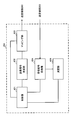
- FIG. 20 is a diagram illustrating an example of a functional configuration of the radio base station according to the present embodiment.
- FIG. 20 mainly shows functional blocks of characteristic portions in the present embodiment, and the wireless base station 10 also has other functional blocks necessary for wireless communication.
- the baseband signal processing unit 104 includes a control unit 301, a transmission signal generation unit 302, a mapping unit 303, a reception signal processing unit 304, and a measurement unit 305.
- the control unit 301 controls the entire radio base station 10.
- the control unit 301 includes, for example, DL signal generation by the transmission signal generation unit 302, DL signal mapping by the mapping unit 303, UL signal reception processing (for example, demodulation) by the reception signal processing unit 304, and measurement unit 305. Control the measurement.
- control unit 301 schedules the user terminal 20. Specifically, the control unit 301 may perform scheduling and / or retransmission control of DL data and / or uplink shared channel based on UCI (for example, CSI and / or BI) from the user terminal 20.
- UCI for example, CSI and / or BI
- control unit 301 may control the configuration (format) of the uplink control channel (for example, the long PUCCH and / or the short PUCCH) and transmit control information related to the uplink control channel.
- control unit 301 may perform multi-slot scheduling in the first to third aspects described above. For example, the number of consecutive slots in the uplink control channel and / or the uplink shared channel may be specified. Moreover, you may designate the first slot allocated to transmission of an uplink control channel and / or an uplink shared channel.
- the control unit 301 may control the reception signal processing unit 304 so as to perform reception processing of UCI from the user terminal 20 based on the format of the uplink control channel.
- the control unit 301 can be configured by a controller, a control circuit, or a control device described based on common recognition in the technical field according to the present invention.
- the transmission signal generation unit 302 generates a DL signal (including a DL data signal, a DL control signal, and a DL reference signal) based on an instruction from the control unit 301, and outputs the DL signal to the mapping unit 303.
- the transmission signal generation unit 302 can be a signal generator, a signal generation circuit, or a signal generation device described based on common recognition in the technical field according to the present invention.
- the mapping unit 303 maps the DL signal generated by the transmission signal generation unit 302 to a predetermined radio resource based on an instruction from the control unit 301, and outputs the DL signal to the transmission / reception unit 103.
- the mapping unit 303 can be a mapper, a mapping circuit, or a mapping device described based on common recognition in the technical field according to the present invention.
- the reception signal processing unit 304 performs reception processing (for example, demapping, demodulation, decoding, etc.) on UL signals (for example, including UL data signals, UL control signals, and UL reference signals) transmitted from the user terminal 20. I do. Specifically, the reception signal processing unit 304 may output a reception signal or a signal after reception processing to the measurement unit 305. Also, the received signal processing unit 304 performs UCI reception processing based on the uplink control channel configuration instructed from the control unit 301.
- reception processing for example, demapping, demodulation, decoding, etc.
- UL signals for example, including UL data signals, UL control signals, and UL reference signals
- the measurement unit 305 performs measurement on the received signal.
- the measurement part 305 can be comprised from the measuring device, measurement circuit, or measurement apparatus demonstrated based on common recognition in the technical field which concerns on this invention.
- the measurement unit 305 measures the UL channel quality based on, for example, the reception power (for example, RSRP (Reference Signal Received Power)) and / or the reception quality (for example, RSRQ (Reference Signal Received Quality)) of the UL reference signal. May be.
- the measurement result may be output to the control unit 301.
- FIG. 21 is a diagram illustrating an example of the overall configuration of the user terminal according to the present embodiment.
- the user terminal 20 includes a plurality of transmission / reception antennas 201 for MIMO transmission, an amplifier unit 202, a transmission / reception unit 203, a baseband signal processing unit 204, and an application unit 205.
- the radio frequency signals received by the plurality of transmission / reception antennas 201 are each amplified by the amplifier unit 202.
- Each transmitting / receiving unit 203 receives the DL signal amplified by the amplifier unit 202.
- the transmission / reception unit 203 converts the frequency of the received signal into a baseband signal and outputs it to the baseband signal processing unit 204.
- the baseband signal processing unit 204 performs FFT processing, error correction decoding, retransmission control reception processing, and the like on the input baseband signal.
- the DL data is transferred to the application unit 205.
- the application unit 205 performs processing related to layers higher than the physical layer and the MAC layer. Broadcast information is also transferred to the application unit 205.
- UL data is input from the application unit 205 to the baseband signal processing unit 204.
- the baseband signal processing unit 204 performs retransmission control transmission processing (for example, HARQ transmission processing), channel coding, rate matching, puncturing, discrete Fourier transform (DFT) processing, IFFT processing, and the like. Are transferred to each transmitting / receiving unit 203. Also for UCI, at least one of channel coding, rate matching, puncturing, DFT processing, and IFFT processing is performed and transferred to each transmission / reception section 203.
- the transmission / reception unit 203 converts the baseband signal output from the baseband signal processing unit 204 into a radio frequency band and transmits it.
- the radio frequency signal frequency-converted by the transmission / reception unit 203 is amplified by the amplifier unit 202 and transmitted from the transmission / reception antenna 201.
- the transmission / reception unit 203 receives a DL signal of a neurology (including a DL data signal, a DL control signal (DCI), and a DL reference signal) set in the user terminal 20, and receives a UL signal of the neurology ( UL data signal, UL control signal, and UL reference signal are transmitted).
- the transmission / reception unit 203 may transmit the UL signal according to the scheduling in the first to third aspects described above. When transmitting the UL signal, transmission may be performed in units of slots and minislots.
- the transmission / reception unit 203 transmits UCI to the radio base station 10 using an uplink shared channel (for example, PUSCH) or an uplink control channel (for example, short PUCCH and / or long PUCCH).
- an uplink shared channel for example, PUSCH
- an uplink control channel for example, short PUCCH and / or long PUCCH.
- the transmission / reception unit 203 may receive information indicating K PUCCH resource sets each including M PUCCH resources. Further, the transmission / reception unit 203 may receive higher layer control information (upper layer parameters).
- the transmission / reception unit 203 can be a transmitter / receiver, a transmission / reception circuit, or a transmission / reception device described based on common recognition in the technical field according to the present invention. Further, the transmission / reception unit 203 may be configured as an integral transmission / reception unit, or may be configured from a transmission unit and a reception unit.
- FIG. 22 is a diagram illustrating an example of a functional configuration of the user terminal according to the present embodiment. Note that FIG. 22 mainly shows functional blocks of characteristic portions in the present embodiment, and the user terminal 20 also has other functional blocks necessary for wireless communication. As illustrated in FIG. 22, the baseband signal processing unit 204 included in the user terminal 20 includes a control unit 401, a transmission signal generation unit 402, a mapping unit 403, a reception signal processing unit 404, and a measurement unit 405. I have.
- the control unit 401 controls the entire user terminal 20. For example, the control unit 401 controls generation of the UL signal by the transmission signal generation unit 402, mapping of the UL signal by the mapping unit 403, reception processing of the DL signal by the reception signal processing unit 404, and measurement by the measurement unit 405.
- control unit 401 controls an uplink control channel used for UCI transmission from the user terminal 20 based on an explicit instruction from the radio base station 10 or an implicit determination in the user terminal 20.
- the control unit 401 controls transmission of the UCI.
- control unit 401 may control the configuration (format) of the uplink control channel (for example, long PUCCH and / or short PUCCH).
- the control unit 401 may control the format of the uplink control channel based on the control information from the radio base station 10. Further, the control unit 401 may control the PUCCH format (uplink control channel format) used for UCI transmission based on the information on fallback.
- PUCCH format uplink control channel format
- control unit 401 may perform UCI on PUSCH control in the first to third aspects described above. For example, time division duplex (TDD) downlink (DL) / uplink (UL) allocation configuration, multiple slots specified for uplink data transmission and multiple slots specified for uplink control information transmission The transmission of uplink control information via the uplink data channel may be controlled based on the relationship (designation by multi-slot scheduling).
- TDD time division duplex
- DL downlink
- UL uplink
- the transmission of uplink control information via the uplink data channel may be controlled based on the relationship (designation by multi-slot scheduling).
- the control unit 401 matches the matched slot when corresponding to the UL in the DL / UL allocation configuration.
- the uplink control information may be transmitted through the uplink data channel.
- the control unit 401 is a slot after the matched slot and corresponding to the UL in the DL / UL allocation configuration. Uplink control information in the matched slot may be transmitted.
- control unit 401 may not transmit the uplink control information in the slot after the matched slot.
- the control unit 401 When the start slot in the plurality of slots designated for the uplink data transmission does not match the start slot in the plurality of slots designated for the uplink control information transmission, the control unit 401 performs the uplink data and the uplink control. Only one of the information may be transmitted.
- the control unit 401 can be configured by a controller, a control circuit, or a control device described based on common recognition in the technical field according to the present invention.
- the transmission signal generation unit 402 generates a UL signal (including UL data signal, UL control signal, UL reference signal, UCI) based on an instruction from the control unit 401 (for example, encoding, rate matching, puncturing, modulation) And the like are output to the mapping unit 403.
- the transmission signal generation unit 402 may be a signal generator, a signal generation circuit, or a signal generation device described based on common recognition in the technical field according to the present invention.
- the mapping unit 403 maps the UL signal generated by the transmission signal generation unit 402 to a radio resource based on an instruction from the control unit 401, and outputs it to the transmission / reception unit 203.
- the mapping unit 403 may be a mapper, a mapping circuit, or a mapping device described based on common recognition in the technical field according to the present invention.
- the reception signal processing unit 404 performs reception processing (for example, demapping, demodulation, decoding, etc.) on the DL signal (DL data signal, scheduling information, DL control signal, DL reference signal).
- the reception signal processing unit 404 outputs information received from the radio base station 10 to the control unit 401.
- the reception signal processing unit 404 outputs, for example, broadcast information, system information, higher layer control information by higher layer signaling such as RRC signaling, physical layer control information (L1 / L2 control information), and the like to the control unit 401.
- the received signal processing unit 404 can be configured by a signal processor, a signal processing circuit, or a signal processing device described based on common recognition in the technical field according to the present invention. Further, the reception signal processing unit 404 can constitute a reception unit according to the present invention.
- the measurement unit 405 measures the channel state based on a reference signal (for example, CSI-RS) from the radio base station 10 and outputs the measurement result to the control unit 401. Note that the channel state measurement may be performed for each CC.
- a reference signal for example, CSI-RS
- the measuring unit 405 can be composed of a signal processor, a signal processing circuit or a signal processing device, and a measuring device, a measurement circuit or a measuring device which are explained based on common recognition in the technical field according to the present invention.
- each functional block is realized using one device physically and / or logically coupled, or directly and / or two or more devices physically and / or logically separated. Alternatively, it may be realized indirectly by connecting (for example, using wired and / or wireless) and using these plural devices.
- a radio base station, a user terminal, etc. in an embodiment of the present invention may function as a computer that performs processing of the radio communication method of the present invention.
- FIG. 23 is a diagram illustrating an example of a hardware configuration of a radio base station and a user terminal according to an embodiment of the present invention.
- the wireless base station 10 and the user terminal 20 described above may be physically configured as a computer device including a processor 1001, a memory 1002, a storage 1003, a communication device 1004, an input device 1005, an output device 1006, a bus 1007, and the like. Good.
- the term “apparatus” can be read as a circuit, a device, a unit, or the like.
- the hardware configurations of the radio base station 10 and the user terminal 20 may be configured to include one or a plurality of each device illustrated in the figure, or may be configured not to include some devices.
- processor 1001 may be implemented by one or more chips.
- Each function in the radio base station 10 and the user terminal 20 is calculated by causing the processor 1001 to perform calculations by reading predetermined software (programs) on hardware such as the processor 1001 and the memory 1002, for example, via the communication device 1004. This is realized by controlling communication and controlling reading and / or writing of data in the memory 1002 and the storage 1003.
- the processor 1001 controls the entire computer by operating an operating system, for example.
- the processor 1001 may be configured by a central processing unit (CPU) including an interface with peripheral devices, a control device, an arithmetic device, a register, and the like.
- CPU central processing unit
- the baseband signal processing unit 104 (204) and the call processing unit 105 described above may be realized by the processor 1001.
- the processor 1001 reads programs (program codes), software modules, data, and the like from the storage 1003 and / or the communication device 1004 to the memory 1002, and executes various processes according to these.
- programs program codes
- software modules software modules
- data data
- the control unit 401 of the user terminal 20 may be realized by a control program stored in the memory 1002 and operating in the processor 1001, and may be realized similarly for other functional blocks.
- the memory 1002 is a computer-readable recording medium such as a ROM (Read Only Memory), an EPROM (Erasable Programmable ROM), an EEPROM (Electrically EPROM), a RAM (Random Access Memory), or any other suitable storage medium. It may be configured by one.
- the memory 1002 may be called a register, a cache, a main memory (main storage device), or the like.
- the memory 1002 can store programs (program codes), software modules, and the like that can be executed to implement the wireless communication method according to an embodiment of the present invention.
- the storage 1003 is a computer-readable recording medium such as a flexible disk, a floppy (registered trademark) disk, a magneto-optical disk (for example, a compact disk (CD-ROM (Compact Disc ROM)), a digital versatile disk, Blu-ray® disk), removable disk, hard disk drive, smart card, flash memory device (eg, card, stick, key drive), magnetic stripe, database, server, or other suitable storage medium It may be constituted by.
- the storage 1003 may be referred to as an auxiliary storage device.
- the communication device 1004 is hardware (transmission / reception device) for performing communication between computers via a wired and / or wireless network, and is also referred to as a network device, a network controller, a network card, a communication module, or the like.
- the communication device 1004 includes, for example, a high-frequency switch, a duplexer, a filter, a frequency synthesizer, etc., in order to realize frequency division duplex (FDD) and / or time division duplex (TDD). It may be configured.
- FDD frequency division duplex
- TDD time division duplex
- the transmission / reception antenna 101 (201), the amplifier unit 102 (202), the transmission / reception unit 103 (203), the transmission path interface 106, and the like described above may be realized by the communication device 1004.
- the input device 1005 is an input device (for example, a keyboard, a mouse, a microphone, a switch, a button, a sensor, etc.) that accepts an input from the outside.
- the output device 1006 is an output device (for example, a display, a speaker, an LED (Light Emitting Diode) lamp, etc.) that performs output to the outside.
- the input device 1005 and the output device 1006 may have an integrated configuration (for example, a touch panel).
- the devices such as the processor 1001 and the memory 1002 are connected by a bus 1007 for communicating information.
- the bus 1007 may be configured using a single bus, or may be configured using a different bus for each device.
- the radio base station 10 and the user terminal 20 include a microprocessor, a digital signal processor (DSP), an ASIC (Application Specific Integrated Circuit), a PLD (Programmable Logic Device), an FPGA (Field Programmable Gate Array), and the like. It may be configured including hardware, and a part or all of each functional block may be realized using the hardware. For example, the processor 1001 may be implemented using at least one of these hardware.
- DSP digital signal processor
- ASIC Application Specific Integrated Circuit
- PLD Programmable Logic Device
- FPGA Field Programmable Gate Array
- the channel and / or symbol may be a signal (signaling).
- the signal may be a message.
- the reference signal may be abbreviated as RS (Reference Signal), and may be referred to as a pilot, a pilot signal, or the like depending on an applied standard.
- a component carrier CC: Component Carrier
- CC Component Carrier
- the radio frame may be configured by one or a plurality of periods (frames) in the time domain.
- Each of the one or more periods (frames) constituting the radio frame may be referred to as a subframe.
- a subframe may be composed of one or more slots in the time domain.
- the subframe may have a fixed time length (eg, 1 ms) that does not depend on the neurology.
- the slot may be configured by one or a plurality of symbols (OFDM (Orthogonal Frequency Division Multiplexing) symbol, SC-FDMA (Single Carrier Frequency Division Multiple Access) symbol, etc.) in the time domain.
- the slot may be a time unit based on the numerology.
- the slot may include a plurality of mini slots. Each minislot may be configured with one or more symbols in the time domain. The minislot may also be called a subslot.
- Radio frame, subframe, slot, minislot, and symbol all represent time units when transmitting signals. Different names may be used for the radio frame, subframe, slot, minislot, and symbol.
- one subframe may be called a transmission time interval (TTI)
- TTI transmission time interval
- a plurality of consecutive subframes may be called a TTI
- TTI slot or one minislot
- a unit representing TTI may be called a slot, a minislot, or the like instead of a subframe.
- TTI means, for example, a minimum time unit for scheduling in wireless communication.
- a radio base station performs scheduling for assigning radio resources (frequency bandwidth, transmission power, etc. that can be used in each user terminal) to each user terminal in units of TTI.
- the definition of TTI is not limited to this.
- the TTI may be a transmission time unit of a channel-encoded data packet (transport block), a code block, and / or a code word, or may be a processing unit such as scheduling or link adaptation.
- a time interval for example, the number of symbols
- a transport block, a code block, and / or a code word is actually mapped may be shorter than the TTI.
- one or more TTIs may be the minimum scheduling unit. Further, the number of slots (the number of mini-slots) constituting the minimum time unit of the scheduling may be controlled.
- a TTI having a time length of 1 ms may be called a normal TTI (TTI in LTE Rel. 8-12), a normal TTI, a long TTI, a normal subframe, a normal subframe, or a long subframe.
- a TTI shorter than a normal TTI may be called a shortened TTI, a short TTI, a partial TTI (partial or fractional TTI), a shortened subframe, a short subframe, a minislot, or a subslot.
- a long TTI (eg, normal TTI, subframe, etc.) may be read as a TTI having a time length exceeding 1 ms, and a short TTI (eg, shortened TTI) is less than the TTI length of the long TTI and 1 ms. It may be replaced with a TTI having the above TTI length.
- a resource block is a resource allocation unit in the time domain and the frequency domain, and may include one or a plurality of continuous subcarriers (subcarriers) in the frequency domain. Further, the RB may include one or a plurality of symbols in the time domain, and may have a length of 1 slot, 1 mini slot, 1 subframe, or 1 TTI. One TTI and one subframe may each be composed of one or a plurality of resource blocks.
- One or more RBs include physical resource blocks (PRB), sub-carrier groups (SCG), resource element groups (REG), PRB pairs, RB pairs, etc. May be called.
- the resource block may be configured by one or a plurality of resource elements (RE: Resource Element).
- RE Resource Element
- 1RE may be a radio resource region of 1 subcarrier and 1 symbol.
- the structure of the above-described radio frame, subframe, slot, minislot, symbol, etc. is merely an example.
- the number of subframes included in a radio frame, the number of slots per subframe or radio frame, the number of minislots included in the slot, the number of symbols and RBs included in the slot or minislot, and the RB The number of subcarriers, the number of symbols in the TTI, the symbol length, the cyclic prefix (CP) length, and the like can be variously changed.
- the information, parameters, and the like described in this specification may be expressed using absolute values, may be expressed using relative values from a predetermined value, or other corresponding information may be used. May be represented.
- the radio resource may be indicated by a predetermined index.
- names used for parameters and the like are not limited names in any way.
- various channels PUCCH (Physical Uplink Control Channel), PDCCH (Physical Downlink Control Channel), etc.
- information elements can be identified by any suitable name, so the various channels and information elements assigned to them.
- the name is not limited in any way.
- information, signals, etc. can be output from the upper layer to the lower layer and / or from the lower layer to the upper layer.
- Information, signals, and the like may be input / output via a plurality of network nodes.
- the input / output information, signals, etc. may be stored in a specific location (for example, a memory) or may be managed using a management table. Input / output information, signals, and the like can be overwritten, updated, or added. The output information, signals, etc. may be deleted. Input information, signals, and the like may be transmitted to other devices.
- information notification includes physical layer signaling (eg, downlink control information (DCI), uplink control information (UCI)), upper layer signaling (eg, RRC (Radio Resource Control) signaling), It may be implemented by broadcast information (Master Information Block (MIB), System Information Block (SIB), etc.), MAC (Medium Access Control) signaling), other signals, or a combination thereof.
- DCI downlink control information
- UCI uplink control information
- RRC Radio Resource Control
- MIB Master Information Block
- SIB System Information Block
- MAC Medium Access Control
- the physical layer signaling may be referred to as L1 / L2 (Layer 1 / Layer 2) control information (L1 / L2 control signal), L1 control information (L1 control signal), or the like.
- the RRC signaling may be referred to as an RRC message, and may be, for example, an RRC connection setup (RRCConnectionSetup) message, an RRC connection reconfiguration (RRCConnectionReconfiguration) message, or the like.
- the MAC signaling may be notified using, for example, a MAC control element (MAC CE (Control Element)).
- notification of predetermined information is not limited to explicit notification, but implicitly (for example, by not performing notification of the predetermined information or other information) May be performed).
- the determination may be performed by a value represented by 1 bit (0 or 1), or may be performed by a boolean value represented by true or false.
- the comparison may be performed by numerical comparison (for example, comparison with a predetermined value).
- software, instructions, information, etc. may be transmitted / received via a transmission medium.
- software can use websites, servers using wired technology (coaxial cable, fiber optic cable, twisted pair, digital subscriber line (DSL), etc.) and / or wireless technology (infrared, microwave, etc.) , Or other remote sources, these wired and / or wireless technologies are included within the definition of transmission media.
- system and “network” may be used interchangeably.
- base station BS
- radio base station eNB
- gNB gNodeB
- cell ector
- cell group e.g., cell group
- carrier carrier
- carrier may be used interchangeably.
- the base station may be referred to by terms such as a fixed station, NodeB, eNodeB (eNB), access point, transmission point, reception point, transmission / reception point, femtocell, and small cell.
- the base station can accommodate one or a plurality of (for example, three) cells (also called sectors). If the base station accommodates multiple cells, the entire coverage area of the base station can be partitioned into multiple smaller areas, each smaller area being a base station subsystem (eg, an indoor small base station (RRH: Remote Radio Head)) can also provide communication services.
- a base station subsystem eg, an indoor small base station (RRH: Remote Radio Head)
- RRH Remote Radio Head
- the term “cell” or “sector” refers to part or all of the coverage area of a base station and / or base station subsystem that provides communication services in this coverage.
- MS mobile station
- UE user equipment
- Mobile station subscriber station, mobile unit, subscriber unit, wireless unit, remote unit, mobile device, wireless device, wireless communication device, remote device, mobile subscriber station, access terminal, mobile terminal, wireless terminal, remote terminal , Handset, user agent, mobile client, client or some other suitable term.
- the base station and / or mobile station may be referred to as a transmission device, a reception device, or the like.
- the radio base station in this specification may be read by the user terminal.
- each aspect / embodiment of the present invention may be applied to a configuration in which communication between a radio base station and a user terminal is replaced with communication between a plurality of user terminals (D2D: Device-to-Device).
- the user terminal 20 may have a function that the wireless base station 10 has.
- words such as “up” and “down” may be read as “side”.
- the uplink channel may be read as a side channel.
- a user terminal in this specification may be read by a radio base station.
- the wireless base station 10 may have a function that the user terminal 20 has.
- the operation performed by the base station may be performed by the upper node in some cases.
- various operations performed for communication with a terminal may include a base station and one or more network nodes other than the base station (for example, It is obvious that this can be done by MME (Mobility Management Entity), S-GW (Serving-Gateway), etc., but not limited thereto) or a combination thereof.
- MME Mobility Management Entity
- S-GW Serving-Gateway
- each aspect / embodiment described in this specification may be used alone, may be used in combination, or may be switched according to execution.
- the order of the processing procedures, sequences, flowcharts, and the like of each aspect / embodiment described in this specification may be changed as long as there is no contradiction.
- the methods described herein present the elements of the various steps in an exemplary order and are not limited to the specific order presented.
- Each aspect / embodiment described in this specification includes LTE (Long Term Evolution), LTE-A (LTE-Advanced), LTE-B (LTE-Beyond), SUPER 3G, IMT-Advanced, 4G (4th generation mobile) communication system), 5G (5th generation mobile communication system), FRA (Future Radio Access), New-RAT (Radio Access Technology), NR (New Radio), NX (New radio access), FX (Future generation radio access), GSM (registered trademark) (Global System for Mobile communications), CDMA2000, UMB (Ultra Mobile Broadband), IEEE 802.11 (Wi-Fi (registered trademark)), IEEE 802.16 (WiMAX (registered trademark)), IEEE 802 .20, UWB (Ultra-WideBand), Bluetooth (registered trademark) ), A system using another appropriate wireless communication method, and / or a next generation system extended based on these methods.
- LTE Long Term Evolution
- LTE-A Long Term Evolution-Advanced
- the phrase “based on” does not mean “based only on”, unless expressly specified otherwise. In other words, the phrase “based on” means both “based only on” and “based at least on.”
- any reference to elements using designations such as “first”, “second”, etc. as used herein does not generally limit the amount or order of those elements. These designations can be used herein as a convenient way to distinguish between two or more elements. Thus, reference to the first and second elements does not mean that only two elements can be employed or that the first element must precede the second element in some way.
- determining may encompass a wide variety of actions. For example, “determination” means calculating, computing, processing, deriving, investigating, looking up (eg, table, database or other data). It may be considered to “judge” (search in structure), ascertaining, etc.
- “determination (decision)” includes receiving (for example, receiving information), transmitting (for example, transmitting information), input (input), output (output), access ( accessing) (e.g., accessing data in memory), etc. may be considered to be “determining”. Also, “determination” is considered to be “determination (resolving)”, “selecting”, “choosing”, “establishing”, “comparing”, etc. Also good. That is, “determination (determination)” may be regarded as “determination (determination)” of some operation.
- connection is any direct or indirect connection between two or more elements or By coupling, it can include the presence of one or more intermediate elements between two elements that are “connected” or “coupled” to each other.
- the coupling or connection between the elements may be physical, logical, or a combination thereof. For example, “connection” may be read as “access”.
- the radio frequency domain can be considered “connected” or “coupled” to each other, such as with electromagnetic energy having wavelengths in the microwave and / or light (both visible and invisible) regions.
Abstract
Description
第1の態様では、マルチスロットスケジューリングにおいて、PUCCHについて指定されたスロット数(Kc)と、PUSCHについて指定されたスロット数(Kd)とが等しく、かつ、開始位置(マルチスロットの最初のスロット)がPUCCHとPUSCHで一致している場合の制御について説明する。
ケース1-1では、上記開始位置からのKc分のスロットが、DL/UL割り当て構成において、全て上りリンク送信が割り当てられている場合(Kc分のスロットに上りリンク送信以外のスロットが含まれていない場合)について説明する。すなわち、上りリンク伝送が割り当てられていないスロット(下りリンク伝送が割り当てられたスロット又は特別スロット)によって、マルチスロットのPUCCH/PUSCH送信が中断されることがない。このような場合、Kc分の全てのスロットにおいて、UCI on PUSCHが行われる。具体的には、図6に示されるようにスロット#0-#3におて、UCI on PUSCHが行われる。
ケース1-2では、上記開始位置からのKc分のスロットが、DL/UL割り当て構成において、下りリンク送信が割り当てられたスロット(又は特別スロット)が存在する場合について説明する。すなわち、下りリンク送信が割り当てられたスロット(又は特別スロット)によって、マルチスロットのPUCCH/PUSCH送信が中断される。このような場合、以下の2つの制御(オプション)が考えられる。
このオプションでは、PUSCHのマルチスロットスケジューリングにおけるルールが、PUCCHのマルチスロットスケジューリングに適用される。上述のように、PUSCHのマルチスロットスケジューリングでは、上りリンク伝送が割り当てられていないスロット(下りリンク伝送が割り当てられたスロット又は特別スロット)によりPUSCH送信を中断した場合、以降のPUSCH送信はキャンセルされる。
このオプションでは、PUCCHのマルチスロットスケジューリングのルールと、PUSCHのマルチスロットスケジューリングのルールの双方が維持される。さらに、PUSCH送信が中断される前のスロットであって、PUSCH及びPUCCHが同時にスケジューリングされているスロットではUCI on PUSCHが行われる。
第2の態様では、マルチスロットスケジューリングにおいて、PUCCHについて指定されたスロット数(Kc)と、PUSCHについて指定されたスロット数(Kd)とが異なる場合、及び/又は、開始位置(マルチスロットの最初のスロット)がPUCCHとPUSCHで一致していない場合の制御について説明する。
このケースでは、マルチスロットのPUCCH/PUSCHが割り当てられた全てのスロットで、PUCCH/PUSCHを送信できる場合について説明する。これは例えば、DL/UL割り当て構成が設定された場合でも、マルチスロットのPUCCH/PUSCHが割り当てられた全てのスロットが、上りリンクスロットである場合(指定されたマルチスロットに上りリンク送信以外のスロットが含まれていない場合)などである。すなわち、マルチスロットのPUCCH/PUSCH送信が、DL/UL割り当て構成によって中断されることがない。
ケース2-1はさらに分類される。このケースでは、PUCCH及びPUSCHの終了スロットは一致しているものとする(図9参照)。このようなケース2-1aでは、以下の制御(オプション)が考えられる。
このオプションでは、PUCCHとPUSCHとが重複するスロットにおいて、UCI on PUSCHが行われる。重複しないスロット、すなわち、PUCCHの送信のみが指定されているスロットについては、PUCCHのみの送信が行われる。このようにすることで、UCIの送信開始時間とULデータの送信開始時間を維持しつつ両者を送信することができるため、端末処理負担増加を抑圧することができる。
このオプションでは、PUCCH送信とPUSCH送信との内、先に開始された送信についてのみ行われ、後から開始される送信はキャンセルする。上記図9においては、PUCCH送信のみが行われ、PUSCH送信はキャンセルされる。このようにすることで、端末はUCI送信開始以降PUSCHの送信処理をする必要がなくなることから、端末処理負担を軽減することができる。
このオプションでは、PUCCH送信とPUSCH送信との内、先に開始された送信をキャンセル(ドロップ)し、後から開始される送信のみが行われる。上記図9においては、PUCCH送信がキャンセルされ、PUSCH送信のみが行われる。なお、先に開始された送信については、ユーザ端末において、可能な限りキャンセル、又は、送信データのドロップが行われる。このようにすることで、時間的に新しいスケジューリング情報を古いスケジューリング情報よりも優先して制御することができるようになるため、低遅延サービスを適切に実現することができる。
ケース2-1はさらに分類される。このケース2-1bでは、スケジューリングされたPUCCHのマルチスロットの開始位置(開始スロット)が、PUSCHの開始位置よりも先であることは、先のケース2-1aと同様であるが、PUCCHの終了スロットがPUSCHの終了スロットよりも早いものとする(図10参照)。このようなケース2-1bでは、以下の制御(オプション)が考えられる。
このオプションでは、PUCCHとPUSCHとが重複するスロットにおいて、UCI on PUSCHが行われる。重複しないスロット、すなわち、PUCCHの送信のみが指定されているスロット、及び、PUSCH送信のみが指定されているスロットについては、それぞれの送信が行われる。
このオプションでは、全てのスロットでUCI on PUSCHが行われる。なお、PUCCHとPUSCHとが重複していないスロットについては、重複しているスロットのUCI又は上りデータをコピーして、UCI on PUSCHが行われる。このようにすることで、マルチスロットのPUSCHに対してスロット間で同様にUCI on PUSCHを適用することができるため(すなわちスロットごとに違うマッピングを適用することがないため)、端末処理負担を軽減できる。また、UCIの送信回数を増加できるので、UCIの品質確保も容易となる。
このオプションでは、PUCCH送信とPUSCH送信との内、先に開始された送信についてのみ行われ、後から開始される送信はキャンセル、又は、重複しないスロットにおいてのみ送信が行われる。具体的には、PUCCH送信のみが行われ、PUSCH送信はキャンセルされる。もしくは、PUCCHのみが指定されているスロット、及び、PUCCH及びPUSCHが重複して指定されているスロット、ではPUCCH送信のみが行われ、さらに、PUSCHのみが指定されているスロットでは、PUSCH送信のみが行われる。このようにすることで、UCIとULデータの両方を送信する機会を設けることができる。また、UCI on PUSCH制御は行わないため、端末処理負担を軽減することができる。
このオプションでは、PUCCH送信とPUSCH送信との内、後に開始された送信についてのみ行われ、先に開始される送信はキャンセル、又は、重複しないスロットにおいてのみ送信が行われる。具体的には、PUSCH送信のみが行われ、PUCCH送信はキャンセルされる。もしくは、PUSCHのみが指定されているスロット、及び、PUCCH及びPUSCHが重複して指定されているスロット、ではPUSCH送信のみが行われ、さらに、PUCCHのみが指定されているスロットでは、PUCCH送信のみが行われる。このようにすることで、時間的に新しいスケジューリング情報を古いスケジューリング情報よりも優先して制御することができるようになるため、低遅延サービスを適切に実現することができる。
ケース2-1はさらに分類される。このケース2-1cでは、スケジューリングされたPUCCHのマルチスロットの開始位置(開始スロット)が、PUSCHの開始位置よりも先であることは、先のケース2-1a、2-1bと同様であるが、PUSCHの終了スロットがPUCCHの終了スロットよりも早いものとする(図11参照)。このようなケース2-1cでは、以下の制御(オプション)が考えられる。
このオプションでは、PUCCHとPUSCHとが重複するスロットにおいて、UCI on PUSCHが行われる。重複しないスロット、すなわち、PUCCHの送信のみが指定されているスロットについては、PUCCHのみの送信が行われる。このようにすることで、UCIの繰り返し回数を確保し、UCIの品質を改善することができる。
このオプションでは、PUCCH送信とPUSCH送信との内、先に開始された送信についてのみ行われ、後から開始される送信はキャンセルする。上記図11においては、PUCCH送信のみが行われ、PUSCH送信はキャンセルされる。
このオプションでは、PUCCH送信とPUSCH送信との内、先に開始された送信についてのみ行われ、後から開始される送信はキャンセル、又は、重複しないスロットにおいてのみ送信が行われる。具体的には、PUCCH送信のみが行われ、PUSCH送信はキャンセルされる。もしくは、PUCCHのみが指定されているスロット、及び、PUCCH及びPUSCHが重複して指定されているスロット、ではPUCCH送信のみが行われ、さらに、PUSCHのみが指定されているスロットでは、PUSCH送信のみが行われる。このようにすることで、ユーザ端末は後の送信を考慮する必要がなくなることから、端末処理負担を軽減することができる。
このケースでは、全てのスロットが、DL/UL割り当て構成において、全て上りリンク送信が割り当てられている場合(指定されたマルチスロットに上りリンク送信以外のスロットが含まれていない場合)であることは、ケース2-1と同じである。すなわち、上りリンク伝送が割り当てられていないスロット(下りリンク伝送が割り当てられたスロット又は特別スロット)によって、マルチスロットのPUCCH/PUSCH送信が中断されることがない。
ケース2-2はさらに分類される。このケースでは、PUCCH及びPUSCHの終了スロットは一致しているものとする(図12参照)。このようなケース2-2aでは、以下の制御(オプション)が考えられる。
このオプションでは、PUCCHとPUSCHとが重複するスロットにおいて、UCI on PUSCHが行われる。重複しないスロット、すなわち、PUSCHの送信のみが指定されているスロットについては、PUSCHのみの送信が行われる。このようにすることで、UCIの送信開始タイミングとULデータの送信開始タイミングを変更することなく両者を適切な回数送信することができるため、端末処理負担増加を抑圧しつつ品質を確保することができる。
このオプションでは、PUCCH送信とPUSCH送信との内、先に開始された送信についてのみ行われ、後から開始される送信はキャンセルする。上記図12においては、PUSCH送信のみが行われ、PUCCH送信はキャンセルされる。このようにすることで、ユーザ端末は後の送信を考慮する必要がなくなることから、端末処理負担を軽減することができる。
このオプションでは、PUCCH送信とPUSCH送信との内、先に開始された送信をキャンセル(ドロップ)し、後から開始される送信のみが行われる。上記図12においては、PUSCH送信がキャンセルされ、PUCCH送信のみが行われる。なお、先に開始された送信については、ユーザ端末において、可能な限りキャンセル、又は、送信データのドロップが行われる。このようにすることで、時間的に新しいスケジューリング情報を古いスケジューリング情報よりも優先して制御することができるようになるため、低遅延サービスを適切に実現することができる。
ケース2-2はさらに分類される。このケース2-2bでは、スケジューリングされたPUSCHのマルチスロットの開始位置(開始スロット)が、PUCCHの開始位置よりも先であることは、先のケース2-2aと同様であるが、PUSCHの終了スロットがPUCCHの終了スロットよりも早いものとする(図13参照)。このようなケース2-2bでは、以下の制御(オプション)が考えられる。
このオプションでは、PUCCHとPUSCHとが重複するスロットにおいて、UCI on PUSCHが行われる。重複しないスロット、すなわち、PUCCHの送信のみが指定されているスロット、及び、PUSCH送信のみが指定されているスロットについては、それぞれの送信が行われる。このようにすることで、UCIの送信開始時間とULデータの送信開始時間を維持しつつ両者を送信することができるため、端末処理負担増加を抑圧することができる。
このオプションでは、重複する最初のスロットから、PUSCHが指定された最後のスロットまで、UCI on PUSCHが行われる。なお、PUCCHとPUSCHとが重複していないスロットについては、重複しているスロットのUCI又はULデータをコピーして、UCI on PUSCHが行われる。このようにすることで、マルチスロットのPUSCHに対してスロット間で同様にUCI on PUSCHを適用することができるため(すなわちスロットごとに違うマッピングを適用することがないため)、端末処理負担を軽減できる。また、UCIの送信回数を増加できるので、UCIの品質確保も容易となる。
このオプションでは、PUCCH送信とPUSCH送信との内、先に開始された送信についてのみ行われ、後から開始される送信はキャンセル、又は、重複しないスロットにおいてのみ送信が行われる。具体的には、PUSCH送信のみが行われ、PUCCH送信はキャンセルされる。もしくは、PUSCHのみが指定されているスロット、及び、PUCCH及びPUSCHが重複して指定されているスロット、ではPUSCH送信のみが行われ、さらに、PUCCHのみが指定されているスロットでは、PUCCH送信のみが行われる。このようにすることで、端末処理負担を軽減しつつ、UCIとULデータの送信スロット数を維持することができる。
このオプションでは、PUCCH送信とPUSCH送信との内、後に開始された送信についてのみ行われ、先に開始される送信はキャンセル、又は、重複しないスロットにおいてのみ送信が行われる。具体的には、PUCCH送信のみが行われ、PUSCH送信はキャンセルされる。もしくは、PUCCHのみが指定されているスロット、及び、PUCCH及びPUSCHが重複して指定されているスロット、ではPUCCH送信のみが行われ、さらに、PUSCHのみが指定されているスロットでは、PUSCH送信のみが行われる。このようにすることで、時間的に新しいスケジューリング情報を古いスケジューリング情報よりも優先して制御することができるようになるため、低遅延サービスを適切に実現することができる。
ケース2-2はさらに分類される。このケース2-2cでは、スケジューリングされたPUCCHのマルチスロットの開始位置(開始スロット)が、PUSCHの開始位置よりも先であることは、先のケース2-2a、2-2bと同様であるが、PUSCHの終了スロットがPUCCHの終了スロットよりも早いものとする(図14参照)。このようなケース2-2cでは、以下の制御(オプション)が考えられる。
このオプションでは、PUCCHとPUSCHとが重複するスロットにおいて、UCI on PUSCHが行われる。重複しないスロット、すなわち、PUCCHの送信のみが指定されているスロットについては、PUCCHのみの送信が行われる。このようにすることで、UCIとULデータの両方について、送信スロット数を維持し、品質を確保することができる。
このオプションでは、PUCCH送信とPUSCH送信との内、先に開始された送信についてのみ行われ、後から開始される送信はキャンセルする。上記図14においては、PUSCH送信のみが行われ、PUCCH送信はキャンセルされる。このようにすることで、端末は後の送信を考慮する必要がなくなることから、端末処理負担を軽減することができる。
このオプションでは、PUCCH送信とPUSCH送信との内、先に開始された送信についてのみ行われ、後から開始される送信はキャンセル、又は、重複しないスロットにおいてのみ送信が行われる。具体的には、PUCCH送信のみが行われ、PUSCH送信はキャンセルされる。もしくは、PUCCHのみが指定されているスロット、及び、PUCCH及びPUSCHが重複して指定されているスロット、ではPUCCH送信のみが行われ、さらに、PUSCHのみが指定されているスロットでは、PUSCH送信のみが行われる。このようにすることで、端端末処理負担を軽減しつつも、UCIとULデータ両者を少なくとも1スロットで送信することができる。
このケースでは、DL/UL割り当て構成において、下りリンク送信が割り当てられたスロット(又は特別スロット)が存在する場合について説明する。すなわち、下りリンク送信が割り当てられたスロット(又は特別スロット)によって、マルチスロットのPUCCH/PUSCH送信が中断される。このような場合、以下の2つの制御(オプション)が考えられる。
このオプションでは、PUSCHのマルチスロットスケジューリングにおけるルールが、PUCCHのマルチスロットスケジューリングに適用される。上述のように、PUSCHのマルチスロットスケジューリングでは、上りリンク伝送が割り当てられていないスロット(下りリンク伝送が割り当てられたスロット又は特別スロット)によりPUSCH送信を中断した場合、以降のPUSCH送信はキャンセルされる。
このオプションでは、PUCCHのマルチスロットスケジューリングのルールと、PUSCHのマルチスロットスケジューリングのルールの双方が維持される。さらに、PUSCH送信が中断される前のスロットであって、PUSCH及びPUCCHが同時にスケジューリングされているスロットではUCI on PUSCHが行われる。
次に第3の態様について説明する。ここでは、ロングPUCCHとミニスロット型PUSCHとの衝突(重複)について説明する。図15は、1スロットの構成が示されている。1スロット内に複数のミニスロット型のPUSCH(ショートPUSCH)が、繰り返しで配置されている。具体的には、kd=1~kd=4まで、シートPUSCHの繰り返しが4回設定されている。
このオプションでは、PUCCH(ロングPUCCH)の送信をキャンセル(ドロップ)する。これにより、予め設定されていたショートPUSCHの繰り返しを維持することができ、かつ端末処理負担の増加を抑圧できる。
このオプションでは、ロングPUCCHとショートPUSCHとが重複している部分(期間)では、PUSCHを送信しない。具体的には、kd=3、4では、PUSCHが送信されない。このようにすることで、のちにスケジューリングされた新しい情報を優先的に送信することができ、低遅延データや低遅延UCIを優先的に送信することができるようになる。
このオプションでは、ロングPUCCHとショートPUSCHとが重複している部分(期間)で、UCI on PUSCHを行う。
以下、本実施の形態に係る無線通信システムの構成について説明する。この無線通信システムでは、上記各態様に係る無線通信方法が適用される。なお、上記各態様に係る無線通信方法は、それぞれ単独で適用されてもよいし、少なくとも2つを組み合わせて適用されてもよい。
図19は、本実施の形態に係る無線基地局の全体構成の一例を示す図である。無線基地局10は、複数の送受信アンテナ101と、アンプ部102と、送受信部103と、ベースバンド信号処理部104と、呼処理部105と、伝送路インターフェース106とを備えている。なお、送受信アンテナ101、アンプ部102、送受信部103は、それぞれ1つ以上を含むように構成されてもよい。
図21は、本実施の形態に係るユーザ端末の全体構成の一例を示す図である。ユーザ端末20は、MIMO伝送のための複数の送受信アンテナ201と、アンプ部202と、送受信部203と、ベースバンド信号処理部204と、アプリケーション部205と、を備えている。
なお、上記実施形態の説明に用いたブロック図は、機能単位のブロックを示している。これらの機能ブロック(構成部)は、ハードウェア及び/又はソフトウェアの任意の組み合わせによって実現される。また、各機能ブロックの実現方法は特に限定されない。すなわち、各機能ブロックは、物理的及び/又は論理的に結合した1つの装置を用いて実現されてもよいし、物理的及び/又は論理的に分離した2つ以上の装置を直接的及び/又は間接的に(例えば、有線及び/又は無線を用いて)接続し、これら複数の装置を用いて実現されてもよい。
なお、本明細書において説明した用語及び/又は本明細書の理解に必要な用語については、同一の又は類似する意味を有する用語と置き換えてもよい。例えば、チャネル及び/又はシンボルは信号(シグナリング)であってもよい。また、信号はメッセージであってもよい。参照信号は、RS(Reference Signal)と略称することもでき、適用される標準によってパイロット(Pilot)、パイロット信号などと呼ばれてもよい。また、コンポーネントキャリア(CC:Component Carrier)は、セル、周波数キャリア、キャリア周波数などと呼ばれてもよい。
Claims (6)
- 上りデータ及び上り制御情報をスロット単位で送信する送信部と、
時分割複信(TDD:Time division duplex)の下りリンク(DL)/上りリンク(UL)割り当て構成と、上りデータ送信に指定される複数スロット及び上り制御情報送信に指定される複数スロットの関係と、に基づいて、上りデータのチャネルを介した上り制御情報の送信を制御する制御部と、を有するユーザ端末。 - 前記制御部は、前記上りデータ送信に指定される複数スロットと、前記上り制御情報送信に指定される複数スロットにおいて、一致したスロットが前記DL/UL割り当て構成におけるULに対応する場合、前記一致したスロットにおいて、前記上りデータのチャネルを介して前記上り制御情報を送信することを特徴とする請求項1に記載のユーザ端末。
- 前記制御部は、前記一致したスロットが、前記DL/UL割り当て構成におけるULに対応しない場合、前記一致したスロット以降のスロットであって、前記DL/UL割り当て構成におけるULに対応するスロットで、前記一致したスロットにおける上り制御情報を送信することを特徴とする請求項1又は請求項2に記載のユーザ端末。
- 前記制御部は、前記一致したスロットが、前記DL/UL割り当て構成におけるULに対応しない場合、前記一致したスロット以降のスロットで前記上り制御情報を送信しないことを特徴とする請求項1又は請求項2に記載のユーザ端末。
- 前記制御部は、前記上りデータ送信に指定される複数スロットの内の開始スロットと、前記上り制御情報送信に指定される複数スロット内の開始スロットとが一致しない場合、前記上りデータ及び前記上り制御情報のいずれか一方の送信のみを行うこと特徴とする請求項1から請求項4のいずれか一項に記載のユーザ端末。
- 上りデータ及び上り制御情報をスロット単位で送信する工程と、
時分割複信(TDD:Time division duplex)の下りリンク(DL)/上りリンク(UL)割り当て構成と、上りデータ送信に指定される複数スロット及び上り制御情報送信に指定される複数スロットの関係と、に基づいて、上りデータのチャネルを介した上り制御情報の送信を制御する工程とを有する、ユーザ端末の無線通信方法。
Priority Applications (8)
| Application Number | Priority Date | Filing Date | Title |
|---|---|---|---|
| AU2018408266A AU2018408266B2 (en) | 2018-02-09 | 2018-02-09 | User terminal and radio communication method |
| MX2020008315A MX2020008315A (es) | 2018-02-09 | 2018-02-09 | Terminal de usuario y metodo de comunicacion por radio. |
| US16/968,399 US20200404651A1 (en) | 2018-02-09 | 2018-02-09 | Terminal, radio communication method, and base station |
| BR112020016102-0A BR112020016102A2 (pt) | 2018-02-09 | 2018-02-09 | Terminal, método de radiocomunicação e estação base |
| CN201880088969.5A CN111699734A (zh) | 2018-02-09 | 2018-02-09 | 用户终端以及无线通信方法 |
| EP18905315.0A EP3751928A4 (en) | 2018-02-09 | 2018-02-09 | USER DEVICE AND RADIO COMMUNICATION PROCEDURE |
| JP2019570270A JP7100067B2 (ja) | 2018-02-09 | 2018-02-09 | 端末、無線通信方法、基地局及びシステム |
| PCT/JP2018/004752 WO2019155641A1 (ja) | 2018-02-09 | 2018-02-09 | ユーザ端末及び無線通信方法 |
Applications Claiming Priority (1)
| Application Number | Priority Date | Filing Date | Title |
|---|---|---|---|
| PCT/JP2018/004752 WO2019155641A1 (ja) | 2018-02-09 | 2018-02-09 | ユーザ端末及び無線通信方法 |
Publications (1)
| Publication Number | Publication Date |
|---|---|
| WO2019155641A1 true WO2019155641A1 (ja) | 2019-08-15 |
Family
ID=67548355
Family Applications (1)
| Application Number | Title | Priority Date | Filing Date |
|---|---|---|---|
| PCT/JP2018/004752 WO2019155641A1 (ja) | 2018-02-09 | 2018-02-09 | ユーザ端末及び無線通信方法 |
Country Status (8)
| Country | Link |
|---|---|
| US (1) | US20200404651A1 (ja) |
| EP (1) | EP3751928A4 (ja) |
| JP (1) | JP7100067B2 (ja) |
| CN (1) | CN111699734A (ja) |
| AU (1) | AU2018408266B2 (ja) |
| BR (1) | BR112020016102A2 (ja) |
| MX (1) | MX2020008315A (ja) |
| WO (1) | WO2019155641A1 (ja) |
Families Citing this family (3)
| Publication number | Priority date | Publication date | Assignee | Title |
|---|---|---|---|---|
| CN110474707B (zh) * | 2018-05-11 | 2022-05-20 | 中兴通讯股份有限公司 | 一种传输方法、装置和系统 |
| US11937256B2 (en) * | 2020-04-14 | 2024-03-19 | Qualcomm Incorporated | Time gaps in multi-slot grants |
| CN117083949A (zh) * | 2021-01-14 | 2023-11-17 | 瑞典爱立信有限公司 | 针对多时隙物理上行链路共享信道上的单个传输块传送的冲突处置、上行链路控制信息复用和重复 |
Family Cites Families (12)
| Publication number | Priority date | Publication date | Assignee | Title |
|---|---|---|---|---|
| EP3154295A4 (en) * | 2014-06-05 | 2018-01-10 | Sharp Kabushiki Kaisha | Terminal device, base station device, and method |
| JP6081531B2 (ja) * | 2015-06-26 | 2017-02-15 | 株式会社Nttドコモ | ユーザ端末、無線基地局及び無線通信方法 |
| EP3389210B1 (en) * | 2015-12-11 | 2022-03-23 | LG Electronics Inc. | Method for transmitting uplink signal and apparatus therefor |
| US10623147B2 (en) * | 2015-12-18 | 2020-04-14 | Lg Electronics Inc. | Method for transmitting uplink control information and user apparatus for carrying out same |
| US20170223695A1 (en) * | 2016-02-03 | 2017-08-03 | Lg Electronics Inc. | Method and apparatus for transmitting an uplink channel in a wireless communication system |
| WO2017171516A1 (ko) * | 2016-04-01 | 2017-10-05 | 엘지전자 주식회사 | 무선 통신 시스템에서 상향링크 제어 정보의 전송 또는 수신 방법 및 이를 위한 장치 |
| JP6744436B2 (ja) * | 2016-07-01 | 2020-08-19 | エルジー エレクトロニクス インコーポレイティド | 無線通信システムにおける基地局と端末との間の上りリンク信号の送受信方法及びそれを支援する装置 |
| JP7013373B2 (ja) * | 2016-07-12 | 2022-01-31 | 株式会社Nttドコモ | 端末、無線通信方法及びシステム |
| US10716100B2 (en) * | 2016-12-13 | 2020-07-14 | Sharp Laboratories Of America, Inc. | Base stations, user equipments, and related communication methods |
| CN110249689B (zh) * | 2017-01-07 | 2022-10-21 | Lg电子株式会社 | 无线通信系统中终端发送上行链路控制信道的方法及使用该方法的通信装置 |
| JP2018019416A (ja) * | 2017-09-25 | 2018-02-01 | 株式会社Nttドコモ | ユーザ端末、基地局及び送信制御方法 |
| US11025456B2 (en) * | 2018-01-12 | 2021-06-01 | Apple Inc. | Time domain resource allocation for mobile communication |
-
2018
- 2018-02-09 US US16/968,399 patent/US20200404651A1/en active Pending
- 2018-02-09 CN CN201880088969.5A patent/CN111699734A/zh active Pending
- 2018-02-09 AU AU2018408266A patent/AU2018408266B2/en active Active
- 2018-02-09 EP EP18905315.0A patent/EP3751928A4/en active Pending
- 2018-02-09 JP JP2019570270A patent/JP7100067B2/ja active Active
- 2018-02-09 BR BR112020016102-0A patent/BR112020016102A2/pt unknown
- 2018-02-09 WO PCT/JP2018/004752 patent/WO2019155641A1/ja unknown
- 2018-02-09 MX MX2020008315A patent/MX2020008315A/es unknown
Non-Patent Citations (3)
| Title |
|---|
| HUAWEI ET AL.: "Discussion on UCI feedback for URLLC", 3GPP TSG-RAN WG1 AH 1801 R1-1800054, 13 January 2018 (2018-01-13), XP051384557 * |
| QUALCOMM INCORPORATED: "Summary of remaining issues for UCI piggyback on PUSCH", 3GPP TSG-RAN WG1 AH 1801 R1-1801263, 29 January 2018 (2018-01-29), XP051385482 * |
| SAMSUNG: "DL and UL Assignment for NR TDD", 3GPP TSG-RAN WG1 AH NR2 R1-1711453, 16 June 2017 (2017-06-16), XP051300638 * |
Also Published As
| Publication number | Publication date |
|---|---|
| AU2018408266B2 (en) | 2023-10-26 |
| EP3751928A4 (en) | 2021-10-06 |
| US20200404651A1 (en) | 2020-12-24 |
| CN111699734A (zh) | 2020-09-22 |
| EP3751928A1 (en) | 2020-12-16 |
| JP7100067B2 (ja) | 2022-07-12 |
| AU2018408266A1 (en) | 2020-09-17 |
| MX2020008315A (es) | 2020-09-21 |
| BR112020016102A2 (pt) | 2020-12-08 |
| JPWO2019155641A1 (ja) | 2021-03-04 |
Similar Documents
| Publication | Publication Date | Title |
|---|---|---|
| WO2018084137A1 (ja) | ユーザ端末及び無線通信方法 | |
| JP7129741B2 (ja) | 端末、無線通信方法及びシステム | |
| JPWO2018203396A1 (ja) | ユーザ端末及び無線通信方法 | |
| WO2018110618A1 (ja) | ユーザ端末及び無線通信方法 | |
| CN110999450B (zh) | 用户终端、无线基站以及无线通信方法 | |
| JP7121040B2 (ja) | 端末、無線通信方法、基地局及びシステム | |
| CN111788806B (zh) | 用户终端以及无线通信方法 | |
| JP7121031B2 (ja) | 端末、無線通信方法、基地局及びシステム | |
| CN111434172B (zh) | 用户终端以及无线通信方法 | |
| CN110999451B (zh) | 用户终端以及无线通信方法 | |
| WO2018128183A1 (ja) | ユーザ端末及び無線通信方法 | |
| WO2019159245A1 (ja) | ユーザ端末及び無線通信方法 | |
| WO2019159292A1 (ja) | ユーザ端末及び無線通信方法 | |
| JP7305551B2 (ja) | 端末、無線通信方法、基地局及びシステム | |
| WO2019077727A1 (ja) | ユーザ端末及び無線通信方法 | |
| JPWO2018173236A1 (ja) | ユーザ端末及び無線通信方法 | |
| WO2019187149A1 (ja) | ユーザ端末及び無線基地局 | |
| WO2019159298A1 (ja) | ユーザ端末及び無線通信方法 | |
| JP7100067B2 (ja) | 端末、無線通信方法、基地局及びシステム | |
| WO2019092823A1 (ja) | ユーザ端末及び無線通信方法 | |
| JP7234139B2 (ja) | 端末、無線通信方法、基地局及びシステム | |
| WO2019215920A1 (ja) | ユーザ端末及び無線基地局 | |
| WO2019215933A1 (ja) | ユーザ端末 | |
| JPWO2019059195A1 (ja) | ユーザ端末及び無線通信方法 | |
| CN111386684A (zh) | 用户终端以及无线通信方法 |
Legal Events
| Date | Code | Title | Description |
|---|---|---|---|
| 121 | Ep: the epo has been informed by wipo that ep was designated in this application |
Ref document number: 18905315 Country of ref document: EP Kind code of ref document: A1 |
|
| ENP | Entry into the national phase |
Ref document number: 2019570270 Country of ref document: JP Kind code of ref document: A |
|
| NENP | Non-entry into the national phase |
Ref country code: DE |
|
| ENP | Entry into the national phase |
Ref document number: 2018905315 Country of ref document: EP Effective date: 20200909 |
|
| ENP | Entry into the national phase |
Ref document number: 2018408266 Country of ref document: AU Date of ref document: 20180209 Kind code of ref document: A |
|
| REG | Reference to national code |
Ref country code: BR Ref legal event code: B01A Ref document number: 112020016102 Country of ref document: BR |
|
| ENP | Entry into the national phase |
Ref document number: 112020016102 Country of ref document: BR Kind code of ref document: A2 Effective date: 20200806 |