WO2019151046A1 - Steel material for line pipes, production method for same, and production method for line pipe - Google Patents
Steel material for line pipes, production method for same, and production method for line pipe Download PDFInfo
- Publication number
- WO2019151046A1 WO2019151046A1 PCT/JP2019/001854 JP2019001854W WO2019151046A1 WO 2019151046 A1 WO2019151046 A1 WO 2019151046A1 JP 2019001854 W JP2019001854 W JP 2019001854W WO 2019151046 A1 WO2019151046 A1 WO 2019151046A1
- Authority
- WO
- WIPO (PCT)
- Prior art keywords
- less
- steel
- temperature
- pipe
- strength
- Prior art date
Links
- 229910000831 Steel Inorganic materials 0.000 title claims abstract description 154
- 239000010959 steel Substances 0.000 title claims abstract description 154
- 238000004519 manufacturing process Methods 0.000 title claims abstract description 35
- 239000000463 material Substances 0.000 title claims abstract description 21
- 238000001816 cooling Methods 0.000 claims abstract description 48
- 238000000034 method Methods 0.000 claims abstract description 41
- 238000005096 rolling process Methods 0.000 claims abstract description 28
- 230000009466 transformation Effects 0.000 claims abstract description 27
- 230000001186 cumulative effect Effects 0.000 claims abstract description 11
- 239000000203 mixture Substances 0.000 claims abstract description 9
- 229910001563 bainite Inorganic materials 0.000 claims description 22
- 238000003303 reheating Methods 0.000 claims description 18
- 239000002184 metal Substances 0.000 claims description 16
- 229910052751 metal Inorganic materials 0.000 claims description 16
- 229910001568 polygonal ferrite Inorganic materials 0.000 claims description 16
- 230000009467 reduction Effects 0.000 claims description 16
- 229910000734 martensite Inorganic materials 0.000 claims description 11
- 238000005098 hot rolling Methods 0.000 claims description 7
- 239000012535 impurity Substances 0.000 claims description 5
- 229910052802 copper Inorganic materials 0.000 claims description 4
- 229910052742 iron Inorganic materials 0.000 claims description 4
- 239000002245 particle Substances 0.000 claims description 4
- 238000001953 recrystallisation Methods 0.000 abstract description 6
- 230000000694 effects Effects 0.000 description 33
- 238000010438 heat treatment Methods 0.000 description 22
- 238000003466 welding Methods 0.000 description 17
- 230000008569 process Effects 0.000 description 13
- 239000002344 surface layer Substances 0.000 description 13
- 230000006835 compression Effects 0.000 description 8
- 238000007906 compression Methods 0.000 description 8
- 230000015572 biosynthetic process Effects 0.000 description 5
- 238000009825 accumulation Methods 0.000 description 4
- VNWKTOKETHGBQD-UHFFFAOYSA-N methane Chemical compound C VNWKTOKETHGBQD-UHFFFAOYSA-N 0.000 description 4
- 239000000126 substance Substances 0.000 description 4
- 238000005452 bending Methods 0.000 description 3
- 229910001567 cementite Inorganic materials 0.000 description 3
- 238000005530 etching Methods 0.000 description 3
- KSOKAHYVTMZFBJ-UHFFFAOYSA-N iron;methane Chemical compound C.[Fe].[Fe].[Fe] KSOKAHYVTMZFBJ-UHFFFAOYSA-N 0.000 description 3
- 102100032884 Neutral amino acid transporter A Human genes 0.000 description 2
- 101710160582 Neutral amino acid transporter A Proteins 0.000 description 2
- 229910001566 austenite Inorganic materials 0.000 description 2
- 239000010953 base metal Substances 0.000 description 2
- 238000012669 compression test Methods 0.000 description 2
- 230000006866 deterioration Effects 0.000 description 2
- 238000009792 diffusion process Methods 0.000 description 2
- 239000007789 gas Substances 0.000 description 2
- 238000010191 image analysis Methods 0.000 description 2
- 230000006698 induction Effects 0.000 description 2
- 150000001247 metal acetylides Chemical class 0.000 description 2
- 238000000465 moulding Methods 0.000 description 2
- 239000003345 natural gas Substances 0.000 description 2
- 229910052758 niobium Inorganic materials 0.000 description 2
- 230000003287 optical effect Effects 0.000 description 2
- 229910001562 pearlite Inorganic materials 0.000 description 2
- 238000005498 polishing Methods 0.000 description 2
- 238000001556 precipitation Methods 0.000 description 2
- 238000005728 strengthening Methods 0.000 description 2
- 238000009864 tensile test Methods 0.000 description 2
- ATJFFYVFTNAWJD-UHFFFAOYSA-N Tin Chemical compound [Sn] ATJFFYVFTNAWJD-UHFFFAOYSA-N 0.000 description 1
- 238000005275 alloying Methods 0.000 description 1
- 238000004364 calculation method Methods 0.000 description 1
- 230000008859 change Effects 0.000 description 1
- 229910052804 chromium Inorganic materials 0.000 description 1
- 230000003749 cleanliness Effects 0.000 description 1
- 238000002485 combustion reaction Methods 0.000 description 1
- 239000002131 composite material Substances 0.000 description 1
- 239000000470 constituent Substances 0.000 description 1
- 238000009749 continuous casting Methods 0.000 description 1
- 239000013078 crystal Substances 0.000 description 1
- 238000000354 decomposition reaction Methods 0.000 description 1
- 238000009826 distribution Methods 0.000 description 1
- 238000000866 electrolytic etching Methods 0.000 description 1
- 230000001771 impaired effect Effects 0.000 description 1
- 230000006872 improvement Effects 0.000 description 1
- 235000013372 meat Nutrition 0.000 description 1
- 238000002844 melting Methods 0.000 description 1
- 230000008018 melting Effects 0.000 description 1
- 238000001000 micrograph Methods 0.000 description 1
- 229910052750 molybdenum Inorganic materials 0.000 description 1
- 229910052759 nickel Inorganic materials 0.000 description 1
- 238000013001 point bending Methods 0.000 description 1
- 239000002994 raw material Substances 0.000 description 1
- 238000007670 refining Methods 0.000 description 1
- 238000004088 simulation Methods 0.000 description 1
- 239000006104 solid solution Substances 0.000 description 1
- 239000002436 steel type Substances 0.000 description 1
- 238000005482 strain hardening Methods 0.000 description 1
- 230000001629 suppression Effects 0.000 description 1
- 230000008719 thickening Effects 0.000 description 1
- 229910052720 vanadium Inorganic materials 0.000 description 1
- XLYOFNOQVPJJNP-UHFFFAOYSA-N water Substances O XLYOFNOQVPJJNP-UHFFFAOYSA-N 0.000 description 1
- 229910000859 α-Fe Inorganic materials 0.000 description 1
Classifications
-
- B—PERFORMING OPERATIONS; TRANSPORTING
- B21—MECHANICAL METAL-WORKING WITHOUT ESSENTIALLY REMOVING MATERIAL; PUNCHING METAL
- B21C—MANUFACTURE OF METAL SHEETS, WIRE, RODS, TUBES OR PROFILES, OTHERWISE THAN BY ROLLING; AUXILIARY OPERATIONS USED IN CONNECTION WITH METAL-WORKING WITHOUT ESSENTIALLY REMOVING MATERIAL
- B21C37/00—Manufacture of metal sheets, bars, wire, tubes or like semi-manufactured products, not otherwise provided for; Manufacture of tubes of special shape
- B21C37/06—Manufacture of metal sheets, bars, wire, tubes or like semi-manufactured products, not otherwise provided for; Manufacture of tubes of special shape of tubes or metal hoses; Combined procedures for making tubes, e.g. for making multi-wall tubes
- B21C37/30—Finishing tubes, e.g. sizing, burnishing
-
- B—PERFORMING OPERATIONS; TRANSPORTING
- B21—MECHANICAL METAL-WORKING WITHOUT ESSENTIALLY REMOVING MATERIAL; PUNCHING METAL
- B21B—ROLLING OF METAL
- B21B3/00—Rolling materials of special alloys so far as the composition of the alloy requires or permits special rolling methods or sequences ; Rolling of aluminium, copper, zinc or other non-ferrous metals
-
- B—PERFORMING OPERATIONS; TRANSPORTING
- B21—MECHANICAL METAL-WORKING WITHOUT ESSENTIALLY REMOVING MATERIAL; PUNCHING METAL
- B21C—MANUFACTURE OF METAL SHEETS, WIRE, RODS, TUBES OR PROFILES, OTHERWISE THAN BY ROLLING; AUXILIARY OPERATIONS USED IN CONNECTION WITH METAL-WORKING WITHOUT ESSENTIALLY REMOVING MATERIAL
- B21C37/00—Manufacture of metal sheets, bars, wire, tubes or like semi-manufactured products, not otherwise provided for; Manufacture of tubes of special shape
- B21C37/06—Manufacture of metal sheets, bars, wire, tubes or like semi-manufactured products, not otherwise provided for; Manufacture of tubes of special shape of tubes or metal hoses; Combined procedures for making tubes, e.g. for making multi-wall tubes
- B21C37/08—Making tubes with welded or soldered seams
- B21C37/0815—Making tubes with welded or soldered seams without continuous longitudinal movement of the sheet during the bending operation
-
- B—PERFORMING OPERATIONS; TRANSPORTING
- B23—MACHINE TOOLS; METAL-WORKING NOT OTHERWISE PROVIDED FOR
- B23K—SOLDERING OR UNSOLDERING; WELDING; CLADDING OR PLATING BY SOLDERING OR WELDING; CUTTING BY APPLYING HEAT LOCALLY, e.g. FLAME CUTTING; WORKING BY LASER BEAM
- B23K31/00—Processes relevant to this subclass, specially adapted for particular articles or purposes, but not covered by only one of the preceding main groups
- B23K31/02—Processes relevant to this subclass, specially adapted for particular articles or purposes, but not covered by only one of the preceding main groups relating to soldering or welding
- B23K31/027—Making tubes with soldering or welding
-
- B—PERFORMING OPERATIONS; TRANSPORTING
- B23—MACHINE TOOLS; METAL-WORKING NOT OTHERWISE PROVIDED FOR
- B23K—SOLDERING OR UNSOLDERING; WELDING; CLADDING OR PLATING BY SOLDERING OR WELDING; CUTTING BY APPLYING HEAT LOCALLY, e.g. FLAME CUTTING; WORKING BY LASER BEAM
- B23K9/00—Arc welding or cutting
- B23K9/02—Seam welding; Backing means; Inserts
- B23K9/025—Seam welding; Backing means; Inserts for rectilinear seams
- B23K9/0253—Seam welding; Backing means; Inserts for rectilinear seams for the longitudinal seam of tubes
-
- B—PERFORMING OPERATIONS; TRANSPORTING
- B23—MACHINE TOOLS; METAL-WORKING NOT OTHERWISE PROVIDED FOR
- B23K—SOLDERING OR UNSOLDERING; WELDING; CLADDING OR PLATING BY SOLDERING OR WELDING; CUTTING BY APPLYING HEAT LOCALLY, e.g. FLAME CUTTING; WORKING BY LASER BEAM
- B23K9/00—Arc welding or cutting
- B23K9/18—Submerged-arc welding
- B23K9/186—Submerged-arc welding making use of a consumable electrodes
- B23K9/188—Submerged-arc welding making use of a consumable electrodes making use of several electrodes
-
- B—PERFORMING OPERATIONS; TRANSPORTING
- B23—MACHINE TOOLS; METAL-WORKING NOT OTHERWISE PROVIDED FOR
- B23K—SOLDERING OR UNSOLDERING; WELDING; CLADDING OR PLATING BY SOLDERING OR WELDING; CUTTING BY APPLYING HEAT LOCALLY, e.g. FLAME CUTTING; WORKING BY LASER BEAM
- B23K9/00—Arc welding or cutting
- B23K9/23—Arc welding or cutting taking account of the properties of the materials to be welded
-
- B—PERFORMING OPERATIONS; TRANSPORTING
- B23—MACHINE TOOLS; METAL-WORKING NOT OTHERWISE PROVIDED FOR
- B23K—SOLDERING OR UNSOLDERING; WELDING; CLADDING OR PLATING BY SOLDERING OR WELDING; CUTTING BY APPLYING HEAT LOCALLY, e.g. FLAME CUTTING; WORKING BY LASER BEAM
- B23K9/00—Arc welding or cutting
- B23K9/235—Preliminary treatment
-
- C—CHEMISTRY; METALLURGY
- C21—METALLURGY OF IRON
- C21D—MODIFYING THE PHYSICAL STRUCTURE OF FERROUS METALS; GENERAL DEVICES FOR HEAT TREATMENT OF FERROUS OR NON-FERROUS METALS OR ALLOYS; MAKING METAL MALLEABLE, e.g. BY DECARBURISATION OR TEMPERING
- C21D1/00—General methods or devices for heat treatment, e.g. annealing, hardening, quenching or tempering
- C21D1/02—Hardening articles or materials formed by forging or rolling, with no further heating beyond that required for the formation
-
- C—CHEMISTRY; METALLURGY
- C21—METALLURGY OF IRON
- C21D—MODIFYING THE PHYSICAL STRUCTURE OF FERROUS METALS; GENERAL DEVICES FOR HEAT TREATMENT OF FERROUS OR NON-FERROUS METALS OR ALLOYS; MAKING METAL MALLEABLE, e.g. BY DECARBURISATION OR TEMPERING
- C21D1/00—General methods or devices for heat treatment, e.g. annealing, hardening, quenching or tempering
- C21D1/18—Hardening; Quenching with or without subsequent tempering
- C21D1/19—Hardening; Quenching with or without subsequent tempering by interrupted quenching
- C21D1/20—Isothermal quenching, e.g. bainitic hardening
-
- C—CHEMISTRY; METALLURGY
- C21—METALLURGY OF IRON
- C21D—MODIFYING THE PHYSICAL STRUCTURE OF FERROUS METALS; GENERAL DEVICES FOR HEAT TREATMENT OF FERROUS OR NON-FERROUS METALS OR ALLOYS; MAKING METAL MALLEABLE, e.g. BY DECARBURISATION OR TEMPERING
- C21D7/00—Modifying the physical properties of iron or steel by deformation
- C21D7/02—Modifying the physical properties of iron or steel by deformation by cold working
- C21D7/10—Modifying the physical properties of iron or steel by deformation by cold working of the whole cross-section, e.g. of concrete reinforcing bars
- C21D7/12—Modifying the physical properties of iron or steel by deformation by cold working of the whole cross-section, e.g. of concrete reinforcing bars by expanding tubular bodies
-
- C—CHEMISTRY; METALLURGY
- C21—METALLURGY OF IRON
- C21D—MODIFYING THE PHYSICAL STRUCTURE OF FERROUS METALS; GENERAL DEVICES FOR HEAT TREATMENT OF FERROUS OR NON-FERROUS METALS OR ALLOYS; MAKING METAL MALLEABLE, e.g. BY DECARBURISATION OR TEMPERING
- C21D8/00—Modifying the physical properties by deformation combined with, or followed by, heat treatment
- C21D8/02—Modifying the physical properties by deformation combined with, or followed by, heat treatment during manufacturing of plates or strips
- C21D8/0221—Modifying the physical properties by deformation combined with, or followed by, heat treatment during manufacturing of plates or strips characterised by the working steps
- C21D8/0226—Hot rolling
-
- C—CHEMISTRY; METALLURGY
- C21—METALLURGY OF IRON
- C21D—MODIFYING THE PHYSICAL STRUCTURE OF FERROUS METALS; GENERAL DEVICES FOR HEAT TREATMENT OF FERROUS OR NON-FERROUS METALS OR ALLOYS; MAKING METAL MALLEABLE, e.g. BY DECARBURISATION OR TEMPERING
- C21D8/00—Modifying the physical properties by deformation combined with, or followed by, heat treatment
- C21D8/02—Modifying the physical properties by deformation combined with, or followed by, heat treatment during manufacturing of plates or strips
- C21D8/0221—Modifying the physical properties by deformation combined with, or followed by, heat treatment during manufacturing of plates or strips characterised by the working steps
- C21D8/0231—Warm rolling
-
- C—CHEMISTRY; METALLURGY
- C21—METALLURGY OF IRON
- C21D—MODIFYING THE PHYSICAL STRUCTURE OF FERROUS METALS; GENERAL DEVICES FOR HEAT TREATMENT OF FERROUS OR NON-FERROUS METALS OR ALLOYS; MAKING METAL MALLEABLE, e.g. BY DECARBURISATION OR TEMPERING
- C21D8/00—Modifying the physical properties by deformation combined with, or followed by, heat treatment
- C21D8/02—Modifying the physical properties by deformation combined with, or followed by, heat treatment during manufacturing of plates or strips
- C21D8/0247—Modifying the physical properties by deformation combined with, or followed by, heat treatment during manufacturing of plates or strips characterised by the heat treatment
- C21D8/0263—Modifying the physical properties by deformation combined with, or followed by, heat treatment during manufacturing of plates or strips characterised by the heat treatment following hot rolling
-
- C—CHEMISTRY; METALLURGY
- C21—METALLURGY OF IRON
- C21D—MODIFYING THE PHYSICAL STRUCTURE OF FERROUS METALS; GENERAL DEVICES FOR HEAT TREATMENT OF FERROUS OR NON-FERROUS METALS OR ALLOYS; MAKING METAL MALLEABLE, e.g. BY DECARBURISATION OR TEMPERING
- C21D8/00—Modifying the physical properties by deformation combined with, or followed by, heat treatment
- C21D8/10—Modifying the physical properties by deformation combined with, or followed by, heat treatment during manufacturing of tubular bodies
- C21D8/105—Modifying the physical properties by deformation combined with, or followed by, heat treatment during manufacturing of tubular bodies of ferrous alloys
-
- C—CHEMISTRY; METALLURGY
- C21—METALLURGY OF IRON
- C21D—MODIFYING THE PHYSICAL STRUCTURE OF FERROUS METALS; GENERAL DEVICES FOR HEAT TREATMENT OF FERROUS OR NON-FERROUS METALS OR ALLOYS; MAKING METAL MALLEABLE, e.g. BY DECARBURISATION OR TEMPERING
- C21D9/00—Heat treatment, e.g. annealing, hardening, quenching or tempering, adapted for particular articles; Furnaces therefor
- C21D9/08—Heat treatment, e.g. annealing, hardening, quenching or tempering, adapted for particular articles; Furnaces therefor for tubular bodies or pipes
-
- C—CHEMISTRY; METALLURGY
- C21—METALLURGY OF IRON
- C21D—MODIFYING THE PHYSICAL STRUCTURE OF FERROUS METALS; GENERAL DEVICES FOR HEAT TREATMENT OF FERROUS OR NON-FERROUS METALS OR ALLOYS; MAKING METAL MALLEABLE, e.g. BY DECARBURISATION OR TEMPERING
- C21D9/00—Heat treatment, e.g. annealing, hardening, quenching or tempering, adapted for particular articles; Furnaces therefor
- C21D9/46—Heat treatment, e.g. annealing, hardening, quenching or tempering, adapted for particular articles; Furnaces therefor for sheet metals
-
- C—CHEMISTRY; METALLURGY
- C22—METALLURGY; FERROUS OR NON-FERROUS ALLOYS; TREATMENT OF ALLOYS OR NON-FERROUS METALS
- C22C—ALLOYS
- C22C38/00—Ferrous alloys, e.g. steel alloys
- C22C38/02—Ferrous alloys, e.g. steel alloys containing silicon
-
- C—CHEMISTRY; METALLURGY
- C22—METALLURGY; FERROUS OR NON-FERROUS ALLOYS; TREATMENT OF ALLOYS OR NON-FERROUS METALS
- C22C—ALLOYS
- C22C38/00—Ferrous alloys, e.g. steel alloys
- C22C38/04—Ferrous alloys, e.g. steel alloys containing manganese
-
- C—CHEMISTRY; METALLURGY
- C22—METALLURGY; FERROUS OR NON-FERROUS ALLOYS; TREATMENT OF ALLOYS OR NON-FERROUS METALS
- C22C—ALLOYS
- C22C38/00—Ferrous alloys, e.g. steel alloys
- C22C38/06—Ferrous alloys, e.g. steel alloys containing aluminium
-
- C—CHEMISTRY; METALLURGY
- C22—METALLURGY; FERROUS OR NON-FERROUS ALLOYS; TREATMENT OF ALLOYS OR NON-FERROUS METALS
- C22C—ALLOYS
- C22C38/00—Ferrous alloys, e.g. steel alloys
- C22C38/08—Ferrous alloys, e.g. steel alloys containing nickel
-
- C—CHEMISTRY; METALLURGY
- C22—METALLURGY; FERROUS OR NON-FERROUS ALLOYS; TREATMENT OF ALLOYS OR NON-FERROUS METALS
- C22C—ALLOYS
- C22C38/00—Ferrous alloys, e.g. steel alloys
- C22C38/12—Ferrous alloys, e.g. steel alloys containing tungsten, tantalum, molybdenum, vanadium, or niobium
-
- C—CHEMISTRY; METALLURGY
- C22—METALLURGY; FERROUS OR NON-FERROUS ALLOYS; TREATMENT OF ALLOYS OR NON-FERROUS METALS
- C22C—ALLOYS
- C22C38/00—Ferrous alloys, e.g. steel alloys
- C22C38/14—Ferrous alloys, e.g. steel alloys containing titanium or zirconium
-
- C—CHEMISTRY; METALLURGY
- C22—METALLURGY; FERROUS OR NON-FERROUS ALLOYS; TREATMENT OF ALLOYS OR NON-FERROUS METALS
- C22C—ALLOYS
- C22C38/00—Ferrous alloys, e.g. steel alloys
- C22C38/16—Ferrous alloys, e.g. steel alloys containing copper
-
- C—CHEMISTRY; METALLURGY
- C22—METALLURGY; FERROUS OR NON-FERROUS ALLOYS; TREATMENT OF ALLOYS OR NON-FERROUS METALS
- C22C—ALLOYS
- C22C38/00—Ferrous alloys, e.g. steel alloys
- C22C38/18—Ferrous alloys, e.g. steel alloys containing chromium
- C22C38/28—Ferrous alloys, e.g. steel alloys containing chromium with titanium or zirconium
-
- C—CHEMISTRY; METALLURGY
- C22—METALLURGY; FERROUS OR NON-FERROUS ALLOYS; TREATMENT OF ALLOYS OR NON-FERROUS METALS
- C22C—ALLOYS
- C22C38/00—Ferrous alloys, e.g. steel alloys
- C22C38/18—Ferrous alloys, e.g. steel alloys containing chromium
- C22C38/40—Ferrous alloys, e.g. steel alloys containing chromium with nickel
- C22C38/42—Ferrous alloys, e.g. steel alloys containing chromium with nickel with copper
-
- C—CHEMISTRY; METALLURGY
- C22—METALLURGY; FERROUS OR NON-FERROUS ALLOYS; TREATMENT OF ALLOYS OR NON-FERROUS METALS
- C22C—ALLOYS
- C22C38/00—Ferrous alloys, e.g. steel alloys
- C22C38/18—Ferrous alloys, e.g. steel alloys containing chromium
- C22C38/40—Ferrous alloys, e.g. steel alloys containing chromium with nickel
- C22C38/44—Ferrous alloys, e.g. steel alloys containing chromium with nickel with molybdenum or tungsten
-
- C—CHEMISTRY; METALLURGY
- C22—METALLURGY; FERROUS OR NON-FERROUS ALLOYS; TREATMENT OF ALLOYS OR NON-FERROUS METALS
- C22C—ALLOYS
- C22C38/00—Ferrous alloys, e.g. steel alloys
- C22C38/18—Ferrous alloys, e.g. steel alloys containing chromium
- C22C38/40—Ferrous alloys, e.g. steel alloys containing chromium with nickel
- C22C38/46—Ferrous alloys, e.g. steel alloys containing chromium with nickel with vanadium
-
- C—CHEMISTRY; METALLURGY
- C22—METALLURGY; FERROUS OR NON-FERROUS ALLOYS; TREATMENT OF ALLOYS OR NON-FERROUS METALS
- C22C—ALLOYS
- C22C38/00—Ferrous alloys, e.g. steel alloys
- C22C38/18—Ferrous alloys, e.g. steel alloys containing chromium
- C22C38/40—Ferrous alloys, e.g. steel alloys containing chromium with nickel
- C22C38/48—Ferrous alloys, e.g. steel alloys containing chromium with nickel with niobium or tantalum
-
- C—CHEMISTRY; METALLURGY
- C22—METALLURGY; FERROUS OR NON-FERROUS ALLOYS; TREATMENT OF ALLOYS OR NON-FERROUS METALS
- C22C—ALLOYS
- C22C38/00—Ferrous alloys, e.g. steel alloys
- C22C38/18—Ferrous alloys, e.g. steel alloys containing chromium
- C22C38/40—Ferrous alloys, e.g. steel alloys containing chromium with nickel
- C22C38/50—Ferrous alloys, e.g. steel alloys containing chromium with nickel with titanium or zirconium
-
- C—CHEMISTRY; METALLURGY
- C22—METALLURGY; FERROUS OR NON-FERROUS ALLOYS; TREATMENT OF ALLOYS OR NON-FERROUS METALS
- C22C—ALLOYS
- C22C38/00—Ferrous alloys, e.g. steel alloys
- C22C38/18—Ferrous alloys, e.g. steel alloys containing chromium
- C22C38/40—Ferrous alloys, e.g. steel alloys containing chromium with nickel
- C22C38/58—Ferrous alloys, e.g. steel alloys containing chromium with nickel with more than 1.5% by weight of manganese
-
- B—PERFORMING OPERATIONS; TRANSPORTING
- B21—MECHANICAL METAL-WORKING WITHOUT ESSENTIALLY REMOVING MATERIAL; PUNCHING METAL
- B21D—WORKING OR PROCESSING OF SHEET METAL OR METAL TUBES, RODS OR PROFILES WITHOUT ESSENTIALLY REMOVING MATERIAL; PUNCHING METAL
- B21D5/00—Bending sheet metal along straight lines, e.g. to form simple curves
- B21D5/01—Bending sheet metal along straight lines, e.g. to form simple curves between rams and anvils or abutments
- B21D5/015—Bending sheet metal along straight lines, e.g. to form simple curves between rams and anvils or abutments for making tubes
-
- B—PERFORMING OPERATIONS; TRANSPORTING
- B23—MACHINE TOOLS; METAL-WORKING NOT OTHERWISE PROVIDED FOR
- B23K—SOLDERING OR UNSOLDERING; WELDING; CLADDING OR PLATING BY SOLDERING OR WELDING; CUTTING BY APPLYING HEAT LOCALLY, e.g. FLAME CUTTING; WORKING BY LASER BEAM
- B23K2101/00—Articles made by soldering, welding or cutting
- B23K2101/04—Tubular or hollow articles
- B23K2101/06—Tubes
-
- B—PERFORMING OPERATIONS; TRANSPORTING
- B23—MACHINE TOOLS; METAL-WORKING NOT OTHERWISE PROVIDED FOR
- B23K—SOLDERING OR UNSOLDERING; WELDING; CLADDING OR PLATING BY SOLDERING OR WELDING; CUTTING BY APPLYING HEAT LOCALLY, e.g. FLAME CUTTING; WORKING BY LASER BEAM
- B23K2103/00—Materials to be soldered, welded or cut
- B23K2103/02—Iron or ferrous alloys
- B23K2103/04—Steel or steel alloys
-
- C—CHEMISTRY; METALLURGY
- C21—METALLURGY OF IRON
- C21D—MODIFYING THE PHYSICAL STRUCTURE OF FERROUS METALS; GENERAL DEVICES FOR HEAT TREATMENT OF FERROUS OR NON-FERROUS METALS OR ALLOYS; MAKING METAL MALLEABLE, e.g. BY DECARBURISATION OR TEMPERING
- C21D2211/00—Microstructure comprising significant phases
- C21D2211/002—Bainite
-
- C—CHEMISTRY; METALLURGY
- C21—METALLURGY OF IRON
- C21D—MODIFYING THE PHYSICAL STRUCTURE OF FERROUS METALS; GENERAL DEVICES FOR HEAT TREATMENT OF FERROUS OR NON-FERROUS METALS OR ALLOYS; MAKING METAL MALLEABLE, e.g. BY DECARBURISATION OR TEMPERING
- C21D2211/00—Microstructure comprising significant phases
- C21D2211/005—Ferrite
Definitions
- the present invention relates to a steel material for a line pipe, a manufacturing method thereof, and a manufacturing method of a line pipe.
- the present invention relates to a steel for line pipe, a method for manufacturing the same, and a method for manufacturing the line pipe, which are suitable for use in oil and natural gas line pipes, particularly for submarine pipelines that require high collapse resistance.
- the compressive strength of this invention means 0.5% compressive yield strength, and is also called compressive yield strength.
- Line pipes used for submarine pipelines are thicker than onshore pipelines and are required to have high roundness in order to prevent collapse due to water pressure. Furthermore, as a characteristic of the line pipe, high compressive strength is required to counter the compressive stress generated in the pipe circumferential direction by external pressure.
- Patent Document 1 discloses a method of maintaining the temperature for a certain time or more after heating and expanding the steel pipe by energization heating.
- Patent Document 2 discloses that the outer surface of the steel pipe is subjected to tensile deformation on the outer surface side by heating to a temperature higher than the inner surface.
- the method of recovering the bausinger effect of the part and maintaining the work hardening of the compression on the inner surface side is disclosed in Patent Document 3 in which accelerated cooling after hot rolling is performed in the steel plate manufacturing process of steel added with Nb and Ti. Methods have been proposed in which heating is performed after the steel pipe is formed by a UOE process from three or more temperatures to 300 ° C. or less.
- Patent Document 4 discloses a method in which the compression ratio at the time of molding with the O press is made larger than the subsequent pipe expansion ratio.
- Patent Document 5 discloses a method for improving the anti-collapse performance by making the diameter near the welded portion with low compressive strength and the diameter at a position of 180 ° from the welded portion the maximum diameter of the steel pipe.
- Patent Document 6 proposes a steel sheet in which the yield stress reduction due to the Bauschinger effect is small by reheating after accelerated cooling to reduce the hard second phase fraction of the steel sheet surface layer.
- Patent Document 7 discloses a method for manufacturing a steel sheet for a high-strength sour line pipe having a thickness of 30 mm or more, in which the surface layer of the steel sheet is heated while suppressing the temperature rise at the center of the steel sheet in the reheating treatment after accelerated cooling. Proposed.
- the heating temperature and heating time of the outer surface and inner surface of the steel pipe must be managed separately. This is difficult in actual production, and it is extremely difficult to control quality in a mass production process. Further, the method described in Patent Document 3 requires that the accelerated cooling stop temperature in the steel plate production be a low temperature of 300 ° C. or lower. For this reason, the distortion of the steel sheet becomes large, the roundness when it is made into a steel pipe by the UOE process is reduced, and further, it is necessary to perform rolling at a relatively high temperature in order to perform accelerated cooling from Ar 3 points or more, and toughness is reduced. There is a problem of deterioration.
- Patent Document 6 The steel sheet described in Patent Document 6 needs to be heated to the center of the steel sheet at the time of reheating, and may cause a drop in DWTT (Drop Weight Tear Test) performance. Application to meat line pipes is difficult. There is also room for improvement from the viewpoint of thickening the steel sheet.
- DWTT Drop Weight Tear Test
- the hard second phase fraction of the steel sheet surface layer portion is reduced while suppressing a decrease in DWTT (Drop Weight Tear Test) performance. For this reason, not only can the hardness of the steel sheet surface layer part be reduced to obtain a steel sheet with small variations in material quality, but it is also expected that the Bausinger effect is reduced by reducing the hard second phase. However, it is difficult for the technique described in Patent Document 7 to stably obtain a strength of X70 grade or higher while ensuring DWTT performance.
- the present invention has been made in view of the above circumstances, has a thickness of 30 mm or more, has high strength necessary for application to a submarine pipeline, and has excellent low-temperature toughness and DWTT performance.
- An object of the present invention is to provide a manufacturing method thereof and a manufacturing method of a line pipe.
- the present inventors diligently studied to achieve both suppression of compressive strength reduction due to the Bauschinger effect and strength and toughness. As a result, the following knowledge was obtained.
- the decrease in compressive strength due to the Bauschinger effect is due to the occurrence of reverse stress (also referred to as back stress) due to dislocation accumulation at the heterogeneous interface or the hard second phase.
- reverse stress also referred to as back stress
- the metal structure can suppress a decrease in compressive strength due to the Bauschinger effect by making the structure mainly composed of bainite that suppresses the formation of soft polygonal ferrite and hard island martensite.
- the present invention has been completed by further studying the above knowledge.
- the gist of the present invention is as follows. [1]% by mass, C: 0.030 to 0.10%, Si: 0.01 to 0.30%, Mn: 1.0 to 2.0%, Nb: 0.005 to 0.050%, Ti: 0.005 to 0.025%, Al: containing 0.08% or less, Furthermore, by mass%, Cu: 0.5% or less, Ni: 1.0% or less, Cr: 1.0% or less, Mo: 0.5% or less, V: containing one or more of 0.1% or less, Ceq value represented by formula (1) is 0.350 or more, Pcm value represented by formula (2) is 0.20 or less, (3) A steel having a component composition consisting of an Ar 3 transformation point represented by the formula of 750 ° C.
- the hot rolling was performed at a rolling reduction temperature of not less than 50% and a rolling reduction temperature of not less than 50% and a rolling completion temperature of not less than Ar 3 transformation point and not more than 790 ° C. at a steel sheet average temperature.
- accelerated cooling is performed from a temperature not lower than the Ar 3 transformation point to a cooling stop temperature of 200 to 450 ° C. at a steel plate average temperature at a cooling rate of 10 ° C./s or higher, and then the steel plate surface temperature is 350 to 550 ° C. and Reheating is performed so that the steel plate center temperature is less than 550 ° C.
- Steel pipe for line pipe manufactured by the method described in [1] is formed into a steel pipe shape by cold forming, and the butt portion is seam welded, and then the pipe expansion rate is 1.2% or less to manufacture a steel pipe.
- the metal structure is mainly bainite, the area fraction of polygonal ferrite is 10% or less, and the area fraction of island martensite is 5% or less at the position of 1/4 of the plate thickness, and the plate thickness 1 /
- the average particle size of bainite at two positions is 10 ⁇ m or less, Steel for line pipes having a tensile strength of 570 MPa or more, a compressive strength of 440 MPa or more, and a plate thickness of 30 mm or more.
- the steel for pipes according to [3] or [4] is formed into a steel pipe shape by cold forming, and the butt portion is seam welded, and then the pipe expansion rate is 1.2% or less to produce a steel pipe.
- the present invention it is possible to obtain a steel material for a line pipe having high strength and excellent low temperature toughness and DWTT performance.
- the present invention is suitable for use in submarine pipelines.
- C is the most effective element for increasing the strength of the steel sheet produced by accelerated cooling. However, if it is less than 0.030%, sufficient strength cannot be ensured. On the other hand, if it exceeds 0.10%, not only is the toughness deteriorated, but also the formation of MA is promoted, resulting in a decrease in compressive strength. Therefore, the C content is specified to be 0.030 to 0.10%. Preferably, it is 0.040% or more, preferably 0.098% or less.
- Si 0.01 to 0.30% Si is contained for deoxidation. However, if it is less than 0.01%, the deoxidation effect is not sufficient. On the other hand, if it exceeds 0.30%, not only the toughness is deteriorated, but also MA formation is promoted, resulting in a decrease in compressive strength. Therefore, the Si content is specified to be 0.01 to 0.30%. Preferably, it is 0.03% or more, preferably 0.25% or less.
- Mn 1.0 to 2.0%
- Mn 1.0 to 2.0%.
- Mn is contained to improve strength and toughness. However, if it is less than 1.0%, the effect is not sufficient, while if it exceeds 2.0%, the toughness is deteriorated. Therefore, the Mn content is specified to be 1.0 to 2.0%. Preferably, it is 1.5% or more, preferably 1.95% or less.
- Nb 0.005 to 0.050%
- Nb improves toughness by refining the structure, further forms carbides, and contributes to an increase in strength. However, if it is less than 0.005%, the effect is not sufficient, while if it exceeds 0.050%, the weld heat affected zone toughness is deteriorated. Therefore, the Nb content is specified to be 0.005 to 0.050%. Preferably, it is 0.010% or more, preferably 0.040% or less.
- Ti 0.005 to 0.025%
- Ti suppresses austenite coarsening during slab heating and improves toughness due to the pinning effect of TiN. However, if it is less than 0.005%, the effect is not sufficient. On the other hand, if it exceeds 0.025%, the toughness is deteriorated. Therefore, the Ti content is specified to be 0.005 to 0.025%. Preferably, it is 0.008% or more, preferably 0.023% or less.
- Al 0.08% or less Al is contained as a deoxidizer. However, if it exceeds 0.08%, the cleanliness of the steel is lowered and the toughness is deteriorated. Therefore, the Al content is specified to be 0.08% or less. Preferably, it is 0.05% or less.
- one or more of Cu: 0.5% or less, Ni: 1.0% or less, Cr: 1.0% or less, Mo: 0.5% or less, V: 0.1% or less are added. contains.
- Cu 0.5% or less
- Cu is an element effective for improving toughness and increasing strength. However, if it exceeds 0.5%, the HAZ toughness of the welded portion deteriorates. Therefore, when it contains Cu, it is 0.5% or less.
- the lower limit is not particularly limited, and the content when Cu is contained is preferably 0.01% or more.
- Ni 1.0% or less
- Ni is an element effective for improving toughness and increasing strength. However, if it exceeds 1.0%, the HAZ toughness of the welded portion may deteriorate. Therefore, when it contains Ni, it is 1.0% or less.
- the lower limit is not particularly limited, and the content when Ni is contained is preferably 0.01% or more.
- Cr 1.0% or less Cr is an element effective for increasing the strength by improving the hardenability. However, if it exceeds 1.0%, the HAZ toughness of the welded portion is deteriorated. Therefore, when it contains Cr, it is 1.0% or less.
- the lower limit is not particularly limited, and the content when Cr is contained is preferably 0.01% or more.
- Mo 0.5% or less Mo is an element effective for improving toughness and increasing strength. However, if it exceeds 0.5%, the HAZ toughness of the welded portion may deteriorate. Therefore, when it contains Mo, it is 0.5% or less.
- the lower limit is not particularly limited, and the content when Mo is contained is preferably 0.01% or more.
- V 0.1% or less V, like Nb and Ti, produces composite carbides and is an extremely effective element for increasing the strength by precipitation strengthening. However, if it exceeds 0.1%, the HAZ toughness of the welded portion may deteriorate. Therefore, when V is contained, the content is made 0.1% or less.
- the lower limit is not particularly limited, and the content when V is contained is preferably 0.01% or more.
- the Ceq value represented by the formula (1) is 0.350 or more
- the Pcm value represented by the formula (2) is 0.20 or less
- the Ar 3 transformation point represented by the formula (3) is It is 750 degrees C or less.
- Ceq value 0.350 or more
- the Ceq value is 0.350 or more.
- the Ceq value is represented by the following formula (1).
- the Ceq value has a correlation with the base material strength and is used as an index of strength. If the Ceq value is less than 0.350, a high strength with a tensile strength of 570 MPa or more cannot be obtained. Therefore, the Ceq value is specified to be 0.350 or more.
- the Ceq value is 0.360 or more.
- Ceq C + Mn / 6 + (Cu + Ni) / 15 + (Cr + Mo + V) / 5 (1)
- the element symbol of the formula (1) indicates mass% of the contained element, and is 0 when not contained.
- Pcm value 0.20 or less Pcm value is 0.20 or less.
- the Pcm value is represented by the following formula (2).
- the Pcm value is used as an index of weldability. The higher the Pcm value, the worse the toughness of the welded HAZ part. Especially in thick high-strength steel, the effect becomes significant, so Pcm needs to be strictly limited. Therefore, the Pcm value is specified to be 0.20 or less. Preferably, the Pcm value is 0.19 or less.
- Pcm C + Si / 30 + (Mn + Cu + Cr) / 20 + Ni / 60 + Mo / 15 + V / 10 (2)
- the element symbol of the formula (2) indicates mass% of the contained element, and is 0 when not contained.
- Ar 3 transformation point 750 ° C. or lower Ar 3 transformation point is 750 ° C. or lower.
- the following formula (3) is a formula representing the Ar 3 transformation point. As the Ar 3 transformation point is higher, ferrite is generated at a higher temperature, so that it is difficult to obtain the metal structure of the present invention, and it is difficult to achieve both compression strength and toughness. Therefore, the component composition is controlled so that the Ar 3 transformation point is 750 ° C. or lower.
- Ar 3 (° C.) 910-310C-80Mn-20Cu-15Cr-55Ni-80Mo (3)
- the element symbol of the formula (3) indicates mass% of the contained element, and is 0 when not contained.
- the balance other than the above components is Fe and inevitable impurities.
- the content of elements other than the above is not a problem as long as the effects of the present invention are not impaired.
- the bainite main body The metal structure of this invention is made into a bainite main body from a viewpoint of suppressing the compressive strength fall by a Bauschinger effect.
- that the metal structure of this invention is a bainite main body means that the area fraction of a bainite is 85% or more with respect to the whole metal structure.
- a bainite single-phase metal structure is desirable in order to avoid dislocation accumulation at the heterogeneous interface or the hard second phase.
- the remaining structure other than bainite is 15% or less.
- the area fraction of bainite is a value at the position of the thickness 1/4.
- the area fraction of polygonal ferrite is 10% or less, and the area fraction of island-like martensite is 5% or less at the thickness 1/4 position. It is desirable to have a uniform structure without a soft polygonal ferrite phase or hard island martensite and to suppress the accumulation of local dislocations generated inside the structure during deformation. Therefore, as described above, the structure is mainly composed of bainite, the area fraction of polygonal ferrite is 10% or less, and the area fraction of island-like martensite is 5% or less at the 1/4 thickness position. Stipulate.
- the area fraction of polygonal ferrite and island martensite may be 0%.
- the fine structure is effective for obtaining a sufficient base material toughness at the position of 1/2 sheet thickness.
- Such an effect can be obtained by setting the grain size of bainite at the position of 1/2 the plate thickness to 10 ⁇ m or less. Therefore, the average particle size of bainite at the position of the plate thickness 1/2 is specified to be 10 ⁇ m or less.
- the metal structure of the present invention may contain other phases other than bainite, polygonal ferrite, and island martensite as long as it has the above-described configuration.
- other phases include pearlite, cementite, and martensite.
- the number of these other phases is preferably small, and the area ratio is preferably 5% or less at the 1/4 position of the plate thickness.
- the steel material for a line pipe according to the present invention preferably has a ratio of compressive strength to tensile strength of 0.748 or higher and a hardness at a position of 1.5 mm from the steel pipe surface of HV260 or lower.
- a ratio of compressive strength to tensile strength is 0.750 or more
- the hardness at a position 1.5 mm from the steel pipe surface is HV256 or less.
- the steel slab containing the above-described chemical components is heated and hot-rolled, subjected to accelerated cooling, and subsequently tempered (re-produced). Heating).
- the temperature is the average temperature in the thickness direction of the steel plate (steel material) unless otherwise specified.
- the average temperature in the plate thickness direction of the steel plate (steel material) is determined by simulation calculation or the like from the plate thickness, surface temperature, cooling conditions, and the like. For example, the average temperature in the plate thickness direction of the steel plate (steel material) is obtained by calculating the temperature distribution in the plate thickness direction using the difference method.
- the steel slab heating temperature is defined as 1000 to 1200 ° C. Preferably, it is 1000 ° C. or higher, preferably 1150 ° C. or lower.
- Cumulative rolling reduction in the non-recrystallization temperature range 60% or more
- cumulative rolling reduction in the temperature range below (rolling end temperature + 20 ° C.) 50% or more
- the cumulative reduction rate in the non-recrystallization temperature region is less than 60% or the cumulative reduction amount in the temperature region below (rolling end temperature + 20 ° C.) is less than 50%, the effect of crystal grain refinement is insufficient. .
- the cumulative rolling reduction in the non-recrystallization temperature region is set to 60% or more and the cumulative rolling amount in the temperature region of (rolling end temperature + 20 ° C.) or less is set to 50% or more.
- the cumulative rolling reduction in the non-recrystallization temperature region is preferably 65% or more.
- the cumulative rolling reduction in the temperature range below (rolling end temperature + 20 ° C.) is preferably 55% or more.
- Rolling end temperature Ar 3 transformation point or higher and 790 ° C. or lower
- Ar 3 transformation point Ar 3 transformation point or higher and 790 ° C. or lower
- the rolling end temperature is specified to be higher than the Ar 3 transformation point.
- the upper limit of the rolling end temperature is set to 790 ° C.
- the rolling end temperature is preferably 780 ° C. or lower.
- Cooling start temperature Ar 3 transformation point or higher
- the cooling start temperature is defined to be higher than the Ar 3 transformation point. Preferably, it is (Ar 3 transformation point + 10 ° C.) or higher.
- Ar 3 transformation point can be obtained by the equation (3) as described above.
- Ar 3 (° C.) 910-310C-80Mn-20Cu-15Cr-55Ni-80Mo (3)
- the element symbol of the formula (3) indicates mass% of the contained element, and is 0 when not contained.
- Cooling rate 10 ° C / s or more
- the accelerated cooling method which is performed at a cooling rate of 10 ° C / s or more, is an indispensable process for obtaining a high-strength, high-toughness steel sheet, and strengthens transformation by cooling at a high cooling rate.
- the effect of increasing the strength can be obtained.
- the cooling rate is less than 10 ° C./s, not only a sufficient strength cannot be obtained, but also C diffusion occurs, so that C is concentrated to untransformed austenite, and the amount of MA produced increases.
- the presence of the hard second phase such as MA promotes the Bauschinger effect, leading to a decrease in compressive strength.
- the cooling rate during accelerated cooling is specified to be 10 ° C./s or more. Preferably, it is 20 ° C./s or more.
- Cooling stop temperature 200-450 ° C
- the cooling stop temperature is defined as 200 to 450 ° C.
- it is 250 degreeC or more, Preferably it is 430 degreeC or less.
- the steel sheet surface temperature during reheating after accelerated cooling is specified to be 350 to 550 ° C. Preferably, it is 400 to 530 ° C.
- Steel plate center temperature during reheating less than 550 ° C.
- the MA of the surface layer is decomposed and high compressive strength is obtained.
- the strength reduction by heating can be suppressed by setting the reheating temperature of the central part of the steel sheet to less than 550 ° C.
- the steel plate center temperature at the time of reheating after accelerated cooling is specified to be less than 550 ° C.
- the means for reheating after accelerated cooling is not particularly limited.
- atmospheric furnace heating, gas combustion, induction heating, etc. can be used.
- induction heating is preferable.
- the manufacturing method of a line pipe makes a steel pipe (line pipe) using the steel plate (steel material) manufactured by the above-mentioned method.
- the steel material forming method include a method of forming into a steel pipe shape by cold forming such as UOE process or press bend (also referred to as bending press).
- UOE process after the groove direction end of a steel plate (steel material) as a raw material is subjected to groove processing, the end bending of the width direction end of the steel plate is performed using a C-shaped press, Using a letter-shaped and O-shaped press, the steel sheet is formed into a cylindrical shape so that the ends in the width direction of the steel sheet face each other.
- seam welding a cylindrical steel plate is constrained, the widthwise ends of the opposing steel plates are butted against each other in a tack welding process, and the seam is applied to the inner and outer surfaces of the butt portion of the steel plate by submerged arc welding.
- a method having a two-step process including a main welding process for performing welding is preferable.
- pipe expansion is performed to remove residual welding stress and improve roundness of the steel pipe.
- the pipe expansion ratio (the ratio of the outer diameter change amount before and after the pipe expansion to the outer diameter of the pipe before the pipe expansion) is 1.2% or less.
- the tube expansion rate is preferably 1.0% or less.
- the pipe expansion rate is preferably 0.4% or more, and more preferably 0.6% or more.
- a steel pipe having a substantially circular cross-sectional shape is manufactured by successively forming a steel plate by repeating three-point bending. Thereafter, seam welding is performed in the same manner as the above-described UOE process. Also in the case of press bend, tube expansion may be performed after seam welding.
- Steels having the chemical composition shown in Table 1 were made into slabs by a continuous casting method, and steel plates (No. 1 to 26) having a thickness of 35 to 40 mm were produced using the slabs. Using these steel plates, steel pipes were manufactured by the UOE process. Seam welding was performed by four-electrode submerged arc welding with one pass on each of the inner and outer surfaces, and the heat input during welding was in the range of 20 to 80 kJ / cm depending on the thickness of the steel sheet.
- Table 2 shows steel plate production conditions and steel pipe production conditions (expansion ratio).
- a tensile test was performed using the full thickness test piece in the pipe circumferential direction as a tensile test piece, and the tensile strength was measured.
- a test piece having a diameter of 20 mm and a length of 60 mm was taken from the position on the inner surface side of the steel pipe in the pipe circumferential direction, and 0.5% compression strength was measured as the compression yield strength by the compression test.
- the temperature at which the ductile fracture surface ratio was 85% was determined as 85% SATT by using a DWTT specimen taken from the pipe circumferential direction of the steel pipe.
- the temperature at which the ductile fracture surface ratio becomes 50% was obtained as vTrs.
- the notch position was a position where there was a melting line at the center of the notch bottom of the Charpy test piece, and the weld metal and the base material (including the heat affected zone including welding) were 1: 1 on the notch bottom.
- the hardness at the position of 1.5mm from the surface of the steel pipe is measured at 20 points at a pitch of 10mm in the circumferential direction of the steel pipe at a position of 1.5mm from the inner surface of the steel pipe with a load of 10kgf (98N) with a Vickers hardness tester. The average value was used.
- the area fraction of bainite and polygonal ferrite was determined by image analysis using three photographs taken at 200 times magnification.
- the MA was observed by performing electrolytic etching (two-stage etching) after nital etching using a sample in which the area fraction of bainite and polygonal ferrite was measured, and then performing observation with a scanning electron microscope (SEM). And the area fraction of MA was calculated
- the average particle size of the bainite was obtained by a line segment method using a micrograph obtained by collecting a sample from a 1 ⁇ 4 position on the inner surface side of the steel tube, etching with nital after polishing, and observing with an optical microscope.
- Table 3 shows the results of the metal structure and mechanical properties.
- the tensile strength is 570 MPa or more
- the compressive strength is 440 MPa or more
- the DWTT performance is 85% SATT is ⁇ 10 ° C. or less
- the HAZ toughness is ⁇ 20 ° C. or less. It was.
- the ratio of the compressive strength to the tensile strength is 0.75 or more
- the hardness at a position 1.5 mm from the surface of the steel pipe is HV260 or less, and a steel pipe having a good roundness is more stable than before. It is effective in manufacturing.
- a steel pipe of API-X70 grade or higher having high strength and excellent low-temperature toughness and DWTT performance can be obtained. Therefore, the steel pipe of the present invention can be applied to a deep sea line pipe that requires high collapse resistance.
Abstract
Description
(a)バウシンガー効果による圧縮強度低下は、異相界面や硬質第2相での転位集積による逆応力(背応力とも言う。)の発生が原因であり、その防止には、第一に転位の集積場所となる軟質相と硬質相との界面を少なくするために、均質な組織とすることが効果的である。そのため、金属組織は、軟質なポリゴナルフェライトや硬質な島状マルテンサイトの生成を抑制したベイナイトを主体とした組織とすることで、バウシンガー効果による圧縮強度低下を抑制できる。
(b)加速冷却によって製造される高強度鋼、特に海底パイプラインに使われるような厚肉の鋼板は、必要な強度を得るために合金元素を多く含有するために焼入れ性が高く、島状マルテンサイト(Martensite-Austenite constituent; 以下、単にMAと称することもある。)の生成を完全に抑制することは困難である。しかし、加速冷却後の再加熱などによってMAをセメンタイトに分解することで、バウシンガー効果による圧縮強度低下を抑制できる。一方、加速冷却後の再加熱は強度低下を招くものの、再加熱温度を一定の温度域に管理することで、必要な強度が得られる。また、再加熱により、引張強度に対して高い圧縮強度を得られ、さらに表層硬さを低減することができるため、良好な真円度の鋼管を安定して製造することが可能となる。
(c)低温靱性を高めるためには、鋼板の熱間圧延時の圧延温度を低温化し組織を微細化することが有効である。しかしながら、圧延温度が低すぎるとポリゴナルフェライトが生成し、加速冷却後の組織がベイナイトとポリゴナルフェライトの混合した組織となりバウシンガー効果が大きくなる。一方で、成分組成を適正化することで、低温で圧延後のポリゴナルフェライト生成を抑制することができ、低温靭性と圧縮強度とを両立できる。さらに、熱間圧延時の圧下量を管理することで、変態の核となる変形帯を多く導入し、組織を微細化することが可能となり、板厚30mm以上の厚肉鋼板においても、高い低温靭性が得られる。 The present inventors diligently studied to achieve both suppression of compressive strength reduction due to the Bauschinger effect and strength and toughness. As a result, the following knowledge was obtained.
(A) The decrease in compressive strength due to the Bauschinger effect is due to the occurrence of reverse stress (also referred to as back stress) due to dislocation accumulation at the heterogeneous interface or the hard second phase. In order to reduce the interface between the soft phase and the hard phase, which are the accumulation locations, it is effective to form a homogeneous structure. Therefore, the metal structure can suppress a decrease in compressive strength due to the Bauschinger effect by making the structure mainly composed of bainite that suppresses the formation of soft polygonal ferrite and hard island martensite.
(B) High-strength steel manufactured by accelerated cooling, especially thick steel plates used in submarine pipelines, have high hardenability because they contain a large amount of alloying elements in order to obtain the required strength. It is difficult to completely suppress the generation of martensite (Martensite-Authentite constituent; hereinafter, also simply referred to as MA). However, by decomposing MA into cementite by reheating after accelerated cooling or the like, it is possible to suppress a decrease in compressive strength due to the Bauschinger effect. On the other hand, although reheating after accelerated cooling causes a decrease in strength, the required strength can be obtained by managing the reheating temperature in a certain temperature range. In addition, by reheating, a high compressive strength with respect to the tensile strength can be obtained, and the surface layer hardness can be reduced, so that a steel pipe having a good roundness can be stably manufactured.
(C) In order to increase the low temperature toughness, it is effective to lower the rolling temperature during hot rolling of the steel sheet and to refine the structure. However, if the rolling temperature is too low, polygonal ferrite is generated, and the structure after accelerated cooling becomes a structure in which bainite and polygonal ferrite are mixed, and the Bauschinger effect is increased. On the other hand, by optimizing the component composition, the formation of polygonal ferrite after rolling at low temperatures can be suppressed, and both low temperature toughness and compressive strength can be achieved. In addition, by controlling the amount of reduction during hot rolling, it becomes possible to introduce a large number of deformation bands that become the core of transformation and refine the structure. Toughness is obtained.
[1]質量%で、C:0.030~0.10%、
Si:0.01~0.30%、
Mn:1.0~2.0%、
Nb:0.005~0.050%、
Ti:0.005~0.025%、
Al:0.08%以下を含有し、
さらに、質量%で、Cu:0.5%以下、
Ni:1.0%以下、
Cr:1.0%以下、
Mo:0.5%以下、
V:0.1%以下の1種以上を含有し、(1)式で表されるCeq値が0.350以上、(2)式で表されるPcm値が0.20以下、(3)式で表されるAr3変態点が750℃以下であり、残部がFeおよび不可避的不純物からなる成分組成を有する鋼を、1000~1200℃の温度に加熱し、未再結晶温度域の累積圧下率が60%以上で、かつ、(圧延終了温度+20℃)以下の温度域の累積圧下率が50%以上、圧延終了温度が鋼板平均温度でAr3変態点以上790℃以下の熱間圧延した後、Ar3変態点以上の温度から10℃/s以上の冷却速度で冷却停止温度が鋼板平均温度で200~450℃まで加速冷却を行い、次いで、鋼板表面温度が350~550℃で、かつ、鋼板中央温度が550℃未満となる再加熱を行う、引張強度570MPa以上、圧縮強度440MPa以上、板厚30mm以上のラインパイプ用鋼材の製造方法。
Ceq=C+Mn/6+(Cu+Ni)/15+(Cr+Mo+V)/5 ・・・(1)
Pcm=C+Si/30+(Mn+Cu+Cr)/20+Ni/60+Mo/15+V/10 ・・・(2)
Ar3(℃)=910-310C-80Mn-20Cu-15Cr-55Ni-80Mo・・・(3)
但し、(1)~(3)式の元素記号は含有元素の質量%を示し、含有しない場合は0とする。
[2][1]に記載の方法で製造されたラインパイプ用鋼材を、冷間成形により鋼管形状とし、突合せ部をシーム溶接後、拡管率が1.2%以下で拡管して鋼管を製造する、引張強度570MPa以上、圧縮強度440MPa以上、板厚30mm以上のラインパイプの製造方法。
[3]質量%で、C:0.030~0.10%、
Si:0.01~0.30%、
Mn:1.0~2.0%、
Nb:0.005~0.050%、
Ti:0.005~0.025%、
Al:0.08%以下を含有し、
さらに、質量%で、Cu:0.5%以下、
Ni:1.0%以下、
Cr:1.0%以下、
Mo:0.5%以下、
V:0.1%以下の1種以上を含有し、(1)式で表されるCeq値が0.350以上、(2)式で表されるPcm値が0.20以下、(3)式で表されるAr3変態点が750℃以下であり、残部がFeおよび不可避的不純物からなる成分組成を有し、
金属組織がベイナイト主体であり、板厚1/4位置において、ポリゴナルフェライトの面積分率が10%以下で、かつ、島状マルテンサイトの面積分率が5%以下であり、板厚1/2位置のベイナイトの平均粒径が10μm以下である、
引張強度570MPa以上、圧縮強度440MPa以上、板厚30mm以上のラインパイプ用鋼材。
Ceq=C+Mn/6+(Cu+Ni)/15+(Cr+Mo+V)/5 ・・・(1)
Pcm=C+Si/30+(Mn+Cu+Cr)/20+Ni/60+Mo/15+V/10 ・・・(2)
Ar3(℃)=910-310C-80Mn-20Cu-15Cr-55Ni-80Mo・・・(3)
但し、(1)~(3)式の元素記号は含有元素の質量%を示し、含有しない場合は0とする。
[4]さらに、引張強度に対する圧縮強度の比が0.748以上、鋼管の内表面から1.5mmの位置における硬さがHV260以下である[3]に記載のラインパイプ用鋼材。
[5][3]または[4]に記載のラインパイプ用鋼材を、冷間成形により鋼管形状とし、突合せ部をシーム溶接後、拡管率が1.2%以下で拡管して鋼管を製造する、引張強度570MPa以上、圧縮強度440MPa以上、板厚30mm以上のラインパイプの製造方法。 The present invention has been completed by further studying the above knowledge. The gist of the present invention is as follows.
[1]% by mass, C: 0.030 to 0.10%,
Si: 0.01 to 0.30%,
Mn: 1.0 to 2.0%,
Nb: 0.005 to 0.050%,
Ti: 0.005 to 0.025%,
Al: containing 0.08% or less,
Furthermore, by mass%, Cu: 0.5% or less,
Ni: 1.0% or less,
Cr: 1.0% or less,
Mo: 0.5% or less,
V: containing one or more of 0.1% or less, Ceq value represented by formula (1) is 0.350 or more, Pcm value represented by formula (2) is 0.20 or less, (3) A steel having a component composition consisting of an Ar 3 transformation point represented by the formula of 750 ° C. or less and the balance consisting of Fe and inevitable impurities is heated to a temperature of 1000 to 1200 ° C. The hot rolling was performed at a rolling reduction temperature of not less than 50% and a rolling reduction temperature of not less than 50% and a rolling completion temperature of not less than Ar 3 transformation point and not more than 790 ° C. at a steel sheet average temperature. Thereafter, accelerated cooling is performed from a temperature not lower than the Ar 3 transformation point to a cooling stop temperature of 200 to 450 ° C. at a steel plate average temperature at a cooling rate of 10 ° C./s or higher, and then the steel plate surface temperature is 350 to 550 ° C. and Reheating is performed so that the steel plate center temperature is less than 550 ° C. Zhang strength 570MPa or more, the compressive strength 440MPa or more, the production method of the steel product for thickness 30mm or more line pipe.
Ceq = C + Mn / 6 + (Cu + Ni) / 15 + (Cr + Mo + V) / 5 (1)
Pcm = C + Si / 30 + (Mn + Cu + Cr) / 20 + Ni / 60 + Mo / 15 + V / 10 (2)
Ar 3 (° C.) = 910-310C-80Mn-20Cu-15Cr-55Ni-80Mo (3)
However, the element symbols in the formulas (1) to (3) indicate the mass% of the contained element, and 0 when not contained.
[2] Steel pipe for line pipe manufactured by the method described in [1] is formed into a steel pipe shape by cold forming, and the butt portion is seam welded, and then the pipe expansion rate is 1.2% or less to manufacture a steel pipe. A method for producing a line pipe having a tensile strength of 570 MPa or more, a compressive strength of 440 MPa or more, and a plate thickness of 30 mm or more.
[3] By mass%, C: 0.030 to 0.10%,
Si: 0.01 to 0.30%,
Mn: 1.0 to 2.0%,
Nb: 0.005 to 0.050%,
Ti: 0.005 to 0.025%,
Al: containing 0.08% or less,
Furthermore, by mass%, Cu: 0.5% or less,
Ni: 1.0% or less,
Cr: 1.0% or less,
Mo: 0.5% or less,
V: containing one or more of 0.1% or less, Ceq value represented by formula (1) is 0.350 or more, Pcm value represented by formula (2) is 0.20 or less, (3) The Ar 3 transformation point represented by the formula is 750 ° C. or less, and the balance has a component composition consisting of Fe and inevitable impurities,
The metal structure is mainly bainite, the area fraction of polygonal ferrite is 10% or less, and the area fraction of island martensite is 5% or less at the position of 1/4 of the plate thickness, and the plate thickness 1 / The average particle size of bainite at two positions is 10 μm or less,
Steel for line pipes having a tensile strength of 570 MPa or more, a compressive strength of 440 MPa or more, and a plate thickness of 30 mm or more.
Ceq = C + Mn / 6 + (Cu + Ni) / 15 + (Cr + Mo + V) / 5 (1)
Pcm = C + Si / 30 + (Mn + Cu + Cr) / 20 + Ni / 60 + Mo / 15 + V / 10 (2)
Ar 3 (° C.) = 910-310C-80Mn-20Cu-15Cr-55Ni-80Mo (3)
However, the element symbols in the formulas (1) to (3) indicate the mass% of the contained element, and 0 when not contained.
[4] The steel product for a line pipe according to [3], wherein the ratio of the compressive strength to the tensile strength is 0.748 or more, and the hardness at a position 1.5 mm from the inner surface of the steel pipe is HV260 or less.
[5] The steel for pipes according to [3] or [4] is formed into a steel pipe shape by cold forming, and the butt portion is seam welded, and then the pipe expansion rate is 1.2% or less to produce a steel pipe. A method for producing a line pipe having a tensile strength of 570 MPa or more, a compressive strength of 440 MPa or more, and a plate thickness of 30 mm or more.
C:0.030~0.10%
Cは、加速冷却によって製造される鋼板の強度を高めるために最も有効な元素である。しかし、0.030%未満では十分な強度を確保できず、一方、0.10%を超えると靭性を劣化させるだけでなく、MAの生成が促進されるため、圧縮強度の低下を招く。従って、C含有量を0.030~0.10%に規定する。好ましくは、0.040%以上であり、好ましくは0.098%以下である。 1. About chemical components C: 0.030 to 0.10%
C is the most effective element for increasing the strength of the steel sheet produced by accelerated cooling. However, if it is less than 0.030%, sufficient strength cannot be ensured. On the other hand, if it exceeds 0.10%, not only is the toughness deteriorated, but also the formation of MA is promoted, resulting in a decrease in compressive strength. Therefore, the C content is specified to be 0.030 to 0.10%. Preferably, it is 0.040% or more, preferably 0.098% or less.
Siは脱酸のため含有させる。しかし、0.01%未満では脱酸効果が十分でなく、一方、0.30%を超えると靭性を劣化させるだけでなく、MA生成が促進されるため、圧縮強度の低下を招く。従って、Si含有量を0.01~0.30%に規定する。好ましくは、0.03%以上であり、好ましくは0.25%以下である。 Si: 0.01 to 0.30%
Si is contained for deoxidation. However, if it is less than 0.01%, the deoxidation effect is not sufficient. On the other hand, if it exceeds 0.30%, not only the toughness is deteriorated, but also MA formation is promoted, resulting in a decrease in compressive strength. Therefore, the Si content is specified to be 0.01 to 0.30%. Preferably, it is 0.03% or more, preferably 0.25% or less.
Mn:1.0~2.0%とする。Mnは強度および靭性向上のために含有する。しかし、1.0%未満ではその効果が十分でなく、一方、2.0%を超えると靭性の劣化を招く。従って、Mn含有量を1.0~2.0%に規定する。好ましくは、1.5%以上であり、好ましくは1.95%以下である。 Mn: 1.0 to 2.0%
Mn: 1.0 to 2.0%. Mn is contained to improve strength and toughness. However, if it is less than 1.0%, the effect is not sufficient, while if it exceeds 2.0%, the toughness is deteriorated. Therefore, the Mn content is specified to be 1.0 to 2.0%. Preferably, it is 1.5% or more, preferably 1.95% or less.
Nbは組織の微細化により靭性を向上させ、さらに炭化物を形成し、強度上昇に寄与する。しかし、0.005%未満ではその効果が十分でなく、一方、0.050%を超えると溶接熱影響部靭性の劣化を招く。従って、Nb含有量を0.005~0.050%に規定する。好ましくは、0.010%以上であり、好ましくは0.040%以下である。 Nb: 0.005 to 0.050%
Nb improves toughness by refining the structure, further forms carbides, and contributes to an increase in strength. However, if it is less than 0.005%, the effect is not sufficient, while if it exceeds 0.050%, the weld heat affected zone toughness is deteriorated. Therefore, the Nb content is specified to be 0.005 to 0.050%. Preferably, it is 0.010% or more, preferably 0.040% or less.
TiはTiNのピニング効果により、スラブ加熱時のオーステナイト粗大化を抑制し、靭性を向上させる。しかし、0.005%未満ではその効果が十分でなく、一方、0.025%を超えると靭性の劣化を招く。従って、Ti含有量を0.005~0.025%に規定する。好ましくは、0.008%以上であり、好ましくは0.023%以下である。 Ti: 0.005 to 0.025%
Ti suppresses austenite coarsening during slab heating and improves toughness due to the pinning effect of TiN. However, if it is less than 0.005%, the effect is not sufficient. On the other hand, if it exceeds 0.025%, the toughness is deteriorated. Therefore, the Ti content is specified to be 0.005 to 0.025%. Preferably, it is 0.008% or more, preferably 0.023% or less.
Alは脱酸剤として含有する。しかし、0.08%を超えると鋼の清浄度が低下し、靭性の劣化を招く。従って、Al含有量を0.08%以下に規定する。好ましくは、0.05%以下である。 Al: 0.08% or less Al is contained as a deoxidizer. However, if it exceeds 0.08%, the cleanliness of the steel is lowered and the toughness is deteriorated. Therefore, the Al content is specified to be 0.08% or less. Preferably, it is 0.05% or less.
Cuは、靱性の改善と強度の上昇に有効な元素である。しかし、0.5%を超えると溶接部のHAZ靱性が劣化する。従って、Cuを含有する場合は0.5%以下とする。一方、下限は特に限定されず、Cuを含有する場合の含有量は0.01%以上とすることが好ましい。 Cu: 0.5% or less Cu is an element effective for improving toughness and increasing strength. However, if it exceeds 0.5%, the HAZ toughness of the welded portion deteriorates. Therefore, when it contains Cu, it is 0.5% or less. On the other hand, the lower limit is not particularly limited, and the content when Cu is contained is preferably 0.01% or more.
Niは、靱性の改善と強度の上昇に有効な元素である。しかし、1.0%を超えると溶接部のHAZ靱性が劣化するおそれがある。従って、Niを含有する場合は1.0%以下とする。一方、下限は特に限定されず、Niを含有する場合の含有量は0.01%以上とすることが好ましい。 Ni: 1.0% or less Ni is an element effective for improving toughness and increasing strength. However, if it exceeds 1.0%, the HAZ toughness of the welded portion may deteriorate. Therefore, when it contains Ni, it is 1.0% or less. On the other hand, the lower limit is not particularly limited, and the content when Ni is contained is preferably 0.01% or more.
Crは、焼き入れ性を高めることで強度の上昇に有効な元素である。しかし、1.0%を超えると溶接部のHAZ靱性を劣化させる。従って、Crを含有する場合は1.0%以下とする。一方、下限は特に限定されず、Crを含有する場合の含有量は0.01%以上とすることが好ましい。 Cr: 1.0% or less Cr is an element effective for increasing the strength by improving the hardenability. However, if it exceeds 1.0%, the HAZ toughness of the welded portion is deteriorated. Therefore, when it contains Cr, it is 1.0% or less. On the other hand, the lower limit is not particularly limited, and the content when Cr is contained is preferably 0.01% or more.
Moは、靱性の改善と強度の上昇に有効な元素である。しかし、0.5%を超えると溶接部のHAZ靱性が劣化するおそれがある。従って、Moを含有する場合は0.5%以下とする。一方、下限は特に限定されず、Moを含有する場合の含有量は0.01%以上とすることが好ましい。 Mo: 0.5% or less Mo is an element effective for improving toughness and increasing strength. However, if it exceeds 0.5%, the HAZ toughness of the welded portion may deteriorate. Therefore, when it contains Mo, it is 0.5% or less. On the other hand, the lower limit is not particularly limited, and the content when Mo is contained is preferably 0.01% or more.
Vは、NbやTiと同様に複合炭化物を生成し、析出強化による強度上昇に極めて有効な元素である。しかし、0.1%を超えると溶接部のHAZ靱性が劣化するおそれがある。従って、Vを含有する場合は0.1%以下とする。一方、下限は特に限定されず、Vを含有する場合の含有量は0.01%以上とすることが好ましい。 V: 0.1% or less V, like Nb and Ti, produces composite carbides and is an extremely effective element for increasing the strength by precipitation strengthening. However, if it exceeds 0.1%, the HAZ toughness of the welded portion may deteriorate. Therefore, when V is contained, the content is made 0.1% or less. On the other hand, the lower limit is not particularly limited, and the content when V is contained is preferably 0.01% or more.
Ceq値は0.350以上とする。Ceq値は下記(1)式で表される。Ceq値は母材強度と相関があり、強度の指標として用いられる。Ceq値が0.350未満では引張強度570MPa以上の高強度が得られない。従って、Ceq値を0.350以上に規定する。好ましくは、Ceq値は0.360以上である。
Ceq=C+Mn/6+(Cu+Ni)/15+(Cr+Mo+V)/5 ・・・(1)
但し、(1)式の元素記号は含有元素の質量%を示し、含有しない場合は0とする。 Ceq value: 0.350 or more The Ceq value is 0.350 or more. The Ceq value is represented by the following formula (1). The Ceq value has a correlation with the base material strength and is used as an index of strength. If the Ceq value is less than 0.350, a high strength with a tensile strength of 570 MPa or more cannot be obtained. Therefore, the Ceq value is specified to be 0.350 or more. Preferably, the Ceq value is 0.360 or more.
Ceq = C + Mn / 6 + (Cu + Ni) / 15 + (Cr + Mo + V) / 5 (1)
However, the element symbol of the formula (1) indicates mass% of the contained element, and is 0 when not contained.
Pcm値は0.20以下とする。Pcm値は下記(2)式で表される。Pcm値は溶接性の指標として用いられ、Pcm値が高いほど溶接HAZ部の靭性が劣化する。特に厚肉高強度鋼では、その影響が顕著となるため、Pcmを厳しく制限する必要がある。従って、Pcm値を0.20以下に規定する。好ましくは、Pcm値は0.19以下である。
Pcm=C+Si/30+(Mn+Cu+Cr)/20+Ni/60+Mo/15+V/10 ・・・(2)
但し、(2)式の元素記号は含有元素の質量%を示し、含有しない場合は0とする。 Pcm value: 0.20 or less Pcm value is 0.20 or less. The Pcm value is represented by the following formula (2). The Pcm value is used as an index of weldability. The higher the Pcm value, the worse the toughness of the welded HAZ part. Especially in thick high-strength steel, the effect becomes significant, so Pcm needs to be strictly limited. Therefore, the Pcm value is specified to be 0.20 or less. Preferably, the Pcm value is 0.19 or less.
Pcm = C + Si / 30 + (Mn + Cu + Cr) / 20 + Ni / 60 + Mo / 15 + V / 10 (2)
However, the element symbol of the formula (2) indicates mass% of the contained element, and is 0 when not contained.
Ar3変態点は750℃以下とする。下記(3)式は、Ar3変態点を表す式である。Ar3変態点が高いほど高温でフェライトが生成するため、本発明の金属組織を得ることが困難となり、また、圧縮強度と靭性の両立が困難となる。従って、Ar3変態点が750℃以下となるように、成分組成を制御する。
Ar3(℃)=910-310C-80Mn-20Cu-15Cr-55Ni-80Mo・・・(3)
但し、(3)式の元素記号は含有元素の質量%を示し、含有しない場合は0とする。 Ar 3 transformation point: 750 ° C. or lower Ar 3 transformation point is 750 ° C. or lower. The following formula (3) is a formula representing the Ar 3 transformation point. As the Ar 3 transformation point is higher, ferrite is generated at a higher temperature, so that it is difficult to obtain the metal structure of the present invention, and it is difficult to achieve both compression strength and toughness. Therefore, the component composition is controlled so that the Ar 3 transformation point is 750 ° C. or lower.
Ar 3 (° C.) = 910-310C-80Mn-20Cu-15Cr-55Ni-80Mo (3)
However, the element symbol of the formula (3) indicates mass% of the contained element, and is 0 when not contained.
ベイナイト主体
本発明の金属組織は、バウシンガー効果による圧縮強度低下を抑制する観点から、ベイナイト主体とする。なお、本発明の金属組織がベイナイト主体であるとは、金属組織全体に対して、ベイナイトの面積分率が85%以上であることをいう。バウシンガー効果による圧縮強度低下を抑制するためには、異相界面や硬質第2相での転位集積を避けるため、ベイナイト単相の金属組織であることが望ましい。なお、ベイナイト以外の残部組織が15%以下であれば許容される。また、ベイナイトの面積分率は、板厚1/4位置における値である。 2. About a metal structure The bainite main body The metal structure of this invention is made into a bainite main body from a viewpoint of suppressing the compressive strength fall by a Bauschinger effect. In addition, that the metal structure of this invention is a bainite main body means that the area fraction of a bainite is 85% or more with respect to the whole metal structure. In order to suppress a decrease in compressive strength due to the Bauschinger effect, a bainite single-phase metal structure is desirable in order to avoid dislocation accumulation at the heterogeneous interface or the hard second phase. In addition, it is permissible if the remaining structure other than bainite is 15% or less. In addition, the area fraction of bainite is a value at the position of the thickness 1/4.
バウシンガー効果を抑制し高い圧縮強度をえるためには、軟質なポリゴナルフェライト相や硬質な島状マルテンサイトのない均一な組織とし、変形時の組織内部で生じる局所的な転位の集積を抑制することが望ましい。そのため、前述したようにベイナイト主体の組織とするとともに、板厚1/4位置において、ポリゴナルフェライトの面積分率が10%以下で、かつ、島状マルテンサイトの面積分率が5%以下に規定する。なお、ポリゴナルフェライトおよび島状マルテンサイトの面積分率は0%であっても構わない。 In order to obtain a high compressive strength by suppressing the Bausinger effect, the area fraction of polygonal ferrite is 10% or less, and the area fraction of island-like martensite is 5% or less at the thickness 1/4 position. It is desirable to have a uniform structure without a soft polygonal ferrite phase or hard island martensite and to suppress the accumulation of local dislocations generated inside the structure during deformation. Therefore, as described above, the structure is mainly composed of bainite, the area fraction of polygonal ferrite is 10% or less, and the area fraction of island-like martensite is 5% or less at the 1/4 thickness position. Stipulate. The area fraction of polygonal ferrite and island martensite may be 0%.
厚肉材の場合、特に板厚1/2位置で十分な母材靱性を得るためには、微細な組織が有効である。そのような効果は、板厚1/2位置のベイナイト粒径を10μm以下にすることで得られる。従って、板厚1/2位置のベイナイトの平均粒径を10μm以下に規定する。 In the case of a thick material, the fine structure is effective for obtaining a sufficient base material toughness at the position of 1/2 sheet thickness. Such an effect can be obtained by setting the grain size of bainite at the position of 1/2 the plate thickness to 10 μm or less. Therefore, the average particle size of bainite at the position of the plate thickness 1/2 is specified to be 10 μm or less.
本発明のラインパイプ用鋼材の製造方法は、上述した化学成分を含有する鋼スラブを、加熱し熱間圧延を行った後、加速冷却を施し、引き続いて焼戻し(再加熱)を行う。以下に、製造条件の限定理由について説明する。なお、以下の説明において、特に断らない限り、温度は鋼板(鋼材)の板厚方向の平均温度とする。鋼板(鋼材)の板厚方向の平均温度は、板厚、表面温度および冷却条件等から、シミュレーション計算等により求められる。例えば、差分法を用い、板厚方向の温度分布を計算することにより、鋼板(鋼材)の板厚方向の平均温度が求められる。 3. Method for Producing Steel for Line Pipe In the method for producing steel for line pipe according to the present invention, the steel slab containing the above-described chemical components is heated and hot-rolled, subjected to accelerated cooling, and subsequently tempered (re-produced). Heating). Below, the reason for limitation of manufacturing conditions is demonstrated. In the following description, the temperature is the average temperature in the thickness direction of the steel plate (steel material) unless otherwise specified. The average temperature in the plate thickness direction of the steel plate (steel material) is determined by simulation calculation or the like from the plate thickness, surface temperature, cooling conditions, and the like. For example, the average temperature in the plate thickness direction of the steel plate (steel material) is obtained by calculating the temperature distribution in the plate thickness direction using the difference method.
鋼スラブ加熱温度は、1000℃未満ではNbCの固溶が不十分で、その後の析出による強化が得られない。一方、1200℃を超えると、低温靱性が劣化する。従って、鋼スラブ加熱温度は1000~1200℃に規定する。好ましくは、1000℃以上であり、好ましくは1150℃以下である。 Steel slab heating temperature: 1000-1200 ℃
When the steel slab heating temperature is less than 1000 ° C., the solid solution of NbC is insufficient and strengthening by subsequent precipitation cannot be obtained. On the other hand, when it exceeds 1200 ° C., the low temperature toughness deteriorates. Therefore, the steel slab heating temperature is defined as 1000 to 1200 ° C. Preferably, it is 1000 ° C. or higher, preferably 1150 ° C. or lower.
高い母材靱性を得るためには、熱間圧延工程において未再結晶温度域で十分な圧下を行う必要がある。しかし、未再結晶温度域の累積圧下率が60%未満、または、(圧延終了温度+20℃)以下の温度域の累積圧下量が50%未満では、結晶粒の微細化効果が不十分である。このため、未再結晶温度域の累積圧下率を60%以上かつ、(圧延終了温度+20℃)以下の温度域の累積圧下量が50%以上とする。未再結晶温度域の累積圧下率は、好ましくは65%以上である。(圧延終了温度+20℃)以下の温度域の累積圧下率は、好ましくは55%以上である。 Cumulative rolling reduction in the non-recrystallization temperature range: 60% or more, and cumulative rolling reduction in the temperature range below (rolling end temperature + 20 ° C.): 50% or more In order to obtain a high base metal toughness, in the hot rolling process It is necessary to perform sufficient reduction in the non-recrystallization temperature range. However, if the cumulative reduction rate in the non-recrystallization temperature region is less than 60% or the cumulative reduction amount in the temperature region below (rolling end temperature + 20 ° C.) is less than 50%, the effect of crystal grain refinement is insufficient. . For this reason, the cumulative rolling reduction in the non-recrystallization temperature region is set to 60% or more and the cumulative rolling amount in the temperature region of (rolling end temperature + 20 ° C.) or less is set to 50% or more. The cumulative rolling reduction in the non-recrystallization temperature region is preferably 65% or more. The cumulative rolling reduction in the temperature range below (rolling end temperature + 20 ° C.) is preferably 55% or more.
バウシンガー効果による強度低下を抑制するためには、金属組織をベイナイト主体の組織としポリゴナルフェライトなどの軟質な組織の生成を抑制する必要がある。そのため、熱間圧延は、ポリゴナルフェライトが生成しない温度域であるAr3変態点以上の温度域で実施することが必要である。従って、圧延終了温度はAr3変態点以上に規定する。さらに、高い母材靱性を得るためにはAr3変態点以上の温度域の中でも低温域で圧延を実施する必要があるため、圧延終了温度の上限を790℃とする。圧延終了温度は好ましくは780℃以下である。 Rolling end temperature: Ar 3 transformation point or higher and 790 ° C. or lower In order to suppress the strength reduction due to the Bausinger effect, it is necessary to suppress the formation of a soft structure such as polygonal ferrite with a metal structure as a bainite-based structure. Therefore, it is necessary to perform hot rolling in a temperature range equal to or higher than the Ar 3 transformation point, which is a temperature range in which polygonal ferrite is not generated. Therefore, the rolling end temperature is specified to be higher than the Ar 3 transformation point. Furthermore, in order to obtain a high base metal toughness, it is necessary to perform rolling in a low temperature region even in a temperature region above the Ar 3 transformation point, so the upper limit of the rolling end temperature is set to 790 ° C. The rolling end temperature is preferably 780 ° C. or lower.
冷却開始温度がAr3変態点未満では、板厚1/4位置におけるポリゴナルフェライトの面積分率が10%を超えて、バウシンガー効果のため、十分な圧縮強度を確保できない。従って、冷却開始温度はAr3変態点以上に規定する。好ましくは、(Ar3変態点+10℃)以上である。 Cooling start temperature: Ar 3 transformation point or higher When the cooling start temperature is less than Ar 3 transformation point, the area fraction of polygonal ferrite at the thickness 1/4 position exceeds 10%, and sufficient compression is achieved due to the Bauschinger effect. Strength cannot be secured. Therefore, the cooling start temperature is defined to be higher than the Ar 3 transformation point. Preferably, it is (Ar 3 transformation point + 10 ° C.) or higher.
Ar3(℃)=910-310C-80Mn-20Cu-15Cr-55Ni-80Mo・・・(3)
但し、(3)式の元素記号は含有元素の質量%を示し、含有しない場合は0とする。 Note that the Ar 3 transformation point can be obtained by the equation (3) as described above.
Ar 3 (° C.) = 910-310C-80Mn-20Cu-15Cr-55Ni-80Mo (3)
However, the element symbol of the formula (3) indicates mass% of the contained element, and is 0 when not contained.
冷却速度を10℃/s以上で行う加速冷却方法は、高強度で高靱性の鋼板を得るために不可欠なプロセスであり、高い冷却速度で冷却することで変態強化による強度上昇効果が得られる。しかし、冷却速度が10℃/s未満では十分な強度が得られないだけでなく、Cの拡散が生じるため未変態オーステナイトへCの濃化が起こり、MAの生成量が多くなる。前述のように、MA等の硬質第2相の存在によって、バウシンガー効果が促進されるため、圧縮強度の低下を招く。しかし、冷却速度が10℃/s以上であれば冷却中のCの拡散が少なく、MAの生成も抑制される。従って、加速冷却時の冷却速度は10℃/s以上に規定する。好ましくは、20℃/s以上である。 Cooling rate: 10 ° C / s or more The accelerated cooling method, which is performed at a cooling rate of 10 ° C / s or more, is an indispensable process for obtaining a high-strength, high-toughness steel sheet, and strengthens transformation by cooling at a high cooling rate. The effect of increasing the strength can be obtained. However, when the cooling rate is less than 10 ° C./s, not only a sufficient strength cannot be obtained, but also C diffusion occurs, so that C is concentrated to untransformed austenite, and the amount of MA produced increases. As described above, the presence of the hard second phase such as MA promotes the Bauschinger effect, leading to a decrease in compressive strength. However, if the cooling rate is 10 ° C./s or more, the diffusion of C during cooling is small, and the production of MA is also suppressed. Therefore, the cooling rate during accelerated cooling is specified to be 10 ° C./s or more. Preferably, it is 20 ° C./s or more.
圧延終了後の加速冷却で200~450℃まで急冷することにより、ベイナイト相を生成させ均一な組織が得られる。しかし、冷却停止温度が200℃未満では、MAが過剰に生成し、バウシンガー効果による圧縮強度低下や、靭性の劣化を招く。一方、冷却停止温度が450℃を超えると、パーライトが生成して、十分な強度が得られないだけでなく、バウシンガー効果により圧縮強度の低下を招く。従って、冷却停止温度は200~450℃に規定する。好ましくは、250℃以上であり、好ましくは430℃以下である。 Cooling stop temperature: 200-450 ° C
By rapidly cooling to 200 to 450 ° C. by accelerated cooling after the end of rolling, a bainite phase is generated and a uniform structure is obtained. However, if the cooling stop temperature is less than 200 ° C., MA is excessively generated, resulting in a decrease in compressive strength due to the Bauschinger effect and a deterioration in toughness. On the other hand, when the cooling stop temperature exceeds 450 ° C., pearlite is generated, and not only a sufficient strength cannot be obtained, but also the compressive strength is lowered due to the Bauschinger effect. Therefore, the cooling stop temperature is defined as 200 to 450 ° C. Preferably, it is 250 degreeC or more, Preferably it is 430 degreeC or less.
上記加速冷却の後、再加熱する。鋼板の加速冷却では鋼板表層部の冷却速度が速くまた鋼板内部に比べ鋼板表層部が低い温度まで冷却される。そのため、鋼板表層部には島状マルテンサイトが生成しやすい。MAのような硬質相はバウシンガー効果を促進するため、加速冷却後に鋼板表層部を加熱しMAを分解することでバウシンガー効果による圧縮強度の低下を抑制することが可能となる。さらに、鋼板表層部を鋼板表面温度で350℃以上に加熱することで、鋼板表層部における硬さを低減することが可能となる。しかし、鋼板表面温度が350℃未満ではMAの分解が十分でなく、また550℃を超えると、鋼板中央部の加熱温度も上昇するため安定して所定の強度を得ることが困難となる。従って、加速冷却後の再加熱時の鋼板表面温度は350~550℃に規定する。好ましくは、400~530℃である。 Steel plate surface temperature during reheating: 350 to 550 ° C
After the accelerated cooling, reheating is performed. In the accelerated cooling of the steel plate, the cooling rate of the steel plate surface layer portion is high, and the steel plate surface layer portion is cooled to a lower temperature than the inside of the steel plate. Therefore, island martensite tends to be generated in the steel plate surface layer. Since a hard phase such as MA promotes the Bauschinger effect, it is possible to suppress a decrease in compressive strength due to the Bauschinger effect by heating the steel sheet surface layer portion after accelerated cooling and decomposing MA. Furthermore, it becomes possible to reduce the hardness in a steel plate surface layer part by heating a steel plate surface layer part to 350 degreeC or more with a steel plate surface temperature. However, if the steel plate surface temperature is less than 350 ° C., the decomposition of MA is not sufficient, and if it exceeds 550 ° C., the heating temperature at the center of the steel plate also rises, making it difficult to obtain a predetermined strength stably. Therefore, the steel sheet surface temperature during reheating after accelerated cooling is specified to be 350 to 550 ° C. Preferably, it is 400 to 530 ° C.
加速冷却後の適切な再加熱によって、表層部のMAが分解され高い圧縮強度が得られる。さらに、鋼板中央部の再加熱温度を550℃未満とすることで、加熱による強度低下を抑制することが可能である。しかし、鋼板中央温度が550℃以上になると、セメンタイトの凝集粗大化がおこり低温靭性が劣化し、さらに安定して所定の強度を得ることが困難となる。従って、加速冷却後の再加熱時の鋼板中央温度は550℃未満に規定する。 Steel plate center temperature during reheating: less than 550 ° C. By appropriate reheating after accelerated cooling, the MA of the surface layer is decomposed and high compressive strength is obtained. Furthermore, the strength reduction by heating can be suppressed by setting the reheating temperature of the central part of the steel sheet to less than 550 ° C. However, when the steel plate center temperature is 550 ° C. or more, cementite is coarsened and coarsened, and the low-temperature toughness is deteriorated. Further, it is difficult to obtain a predetermined strength stably. Therefore, the steel plate center temperature at the time of reheating after accelerated cooling is specified to be less than 550 ° C.
本発明は上述の方法によって製造された鋼板(鋼材)を用いて鋼管(ラインパイプ)となす。鋼材の成形方法としては、UOEプロセスやプレスベンド(ベンディングプレスとも称する。)等の冷間成形によって鋼管形状に成形する方法が挙げられる。UOEプロセスでは、素材となる鋼板(鋼材)の幅方向端部に開先加工を施したのち、C字状のプレス機を用いて鋼板の幅方向端部の端曲げを行い、続いて、U字状及びO字状のプレス機を用いて鋼板の幅方向端部同士が対向するように鋼板を円筒形状に成形する。次いで、鋼板の対向する幅方向端部を突き合わせて溶接する。この溶接をシーム溶接と呼ぶ。このシーム溶接においては、円筒形状の鋼板を拘束し、対向する鋼板の幅方向端部同士を突き合わせて仮付溶接する仮付溶接工程と、サブマージアーク溶接法によって鋼板の突合せ部の内外面にシーム溶接を施す本溶接工程との、二段階の工程を有する方法が好ましい。シーム溶接を行った後に、溶接残留応力の除去と鋼管真円度の向上のため、拡管を行う。拡管工程において拡管率(拡管前の管の外径に対する拡管前後の外径変化量の比)は、1.2%以下とする。これは、拡管率が大きすぎるとバウシンガー効果により圧縮強度の低下が大きくなるためであり、拡管率は1.0%以下であることが好ましい。なお、溶接残留応力を低減し、また、鋼管の真円度を向上させる観点から、拡管率は0.4%以上であることが好ましく、0.6%以上であることがより好ましい。 4). The manufacturing method of a line pipe This invention makes a steel pipe (line pipe) using the steel plate (steel material) manufactured by the above-mentioned method. Examples of the steel material forming method include a method of forming into a steel pipe shape by cold forming such as UOE process or press bend (also referred to as bending press). In the UOE process, after the groove direction end of a steel plate (steel material) as a raw material is subjected to groove processing, the end bending of the width direction end of the steel plate is performed using a C-shaped press, Using a letter-shaped and O-shaped press, the steel sheet is formed into a cylindrical shape so that the ends in the width direction of the steel sheet face each other. Next, the opposing widthwise ends of the steel plates are butted and welded. This welding is called seam welding. In this seam welding, a cylindrical steel plate is constrained, the widthwise ends of the opposing steel plates are butted against each other in a tack welding process, and the seam is applied to the inner and outer surfaces of the butt portion of the steel plate by submerged arc welding. A method having a two-step process including a main welding process for performing welding is preferable. After seam welding, pipe expansion is performed to remove residual welding stress and improve roundness of the steel pipe. In the pipe expansion process, the pipe expansion ratio (the ratio of the outer diameter change amount before and after the pipe expansion to the outer diameter of the pipe before the pipe expansion) is 1.2% or less. This is because if the tube expansion rate is too large, the decrease in compressive strength increases due to the Bauschinger effect, and the tube expansion rate is preferably 1.0% or less. In addition, from the viewpoint of reducing welding residual stress and improving the roundness of the steel pipe, the pipe expansion rate is preferably 0.4% or more, and more preferably 0.6% or more.
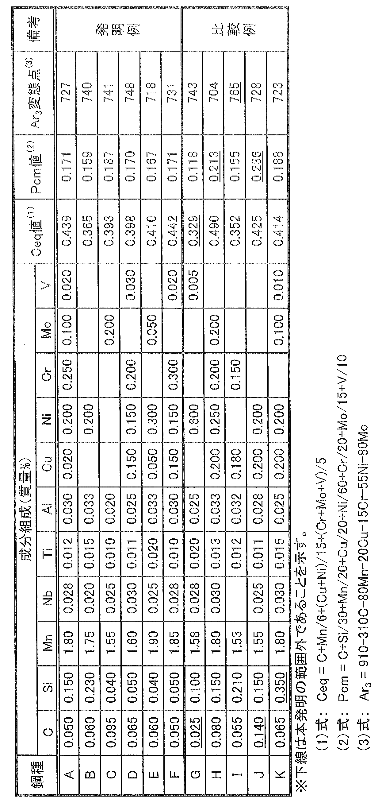


Claims (5)
- 質量%で、C:0.030~0.10%、
Si:0.01~0.30%、
Mn:1.0~2.0%、
Nb:0.005~0.050%、
Ti:0.005~0.025%、
Al:0.08%以下を含有し、
さらに、質量%で、Cu:0.5%以下、
Ni:1.0%以下、
Cr:1.0%以下、
Mo:0.5%以下、
V:0.1%以下の1種以上を含有し、(1)式で表されるCeq値が0.350以上、(2)式で表されるPcm値が0.20以下、(3)式で表されるAr3変態点が750℃以下であり、残部がFeおよび不可避的不純物からなる成分組成を有する鋼を、1000~1200℃の温度に加熱し、未再結晶温度域の累積圧下率が60%以上で、かつ、(圧延終了温度+20℃)以下の温度域の累積圧下率が50%以上、圧延終了温度が鋼板平均温度でAr3変態点以上790℃以下の熱間圧延した後、Ar3変態点以上の温度から10℃/s以上の冷却速度で冷却停止温度が鋼板平均温度で200~450℃まで加速冷却を行い、次いで、鋼板表面温度が350~550℃で、かつ、鋼板中央温度が550℃未満となる再加熱を行う、引張強度570MPa以上、圧縮強度440MPa以上、板厚30mm以上のラインパイプ用鋼材の製造方法。
Ceq=C+Mn/6+(Cu+Ni)/15+(Cr+Mo+V)/5 ・・・(1)
Pcm=C+Si/30+(Mn+Cu+Cr)/20+Ni/60+Mo/15+V/10 ・・・(2)
Ar3(℃)=910-310C-80Mn-20Cu-15Cr-55Ni-80Mo・・・(3)
但し、(1)~(3)式の元素記号は含有元素の質量%を示し、含有しない場合は0とする。 % By mass, C: 0.030 to 0.10%,
Si: 0.01 to 0.30%,
Mn: 1.0 to 2.0%,
Nb: 0.005 to 0.050%,
Ti: 0.005 to 0.025%,
Al: containing 0.08% or less,
Furthermore, by mass%, Cu: 0.5% or less,
Ni: 1.0% or less,
Cr: 1.0% or less,
Mo: 0.5% or less,
V: containing one or more of 0.1% or less, Ceq value represented by formula (1) is 0.350 or more, Pcm value represented by formula (2) is 0.20 or less, (3) A steel having a component composition consisting of an Ar 3 transformation point represented by the formula of 750 ° C. or less and the balance consisting of Fe and inevitable impurities is heated to a temperature of 1000 to 1200 ° C. The hot rolling was performed at a rate of 60% or more and a cumulative rolling reduction in a temperature range of (rolling end temperature + 20 ° C.) or lower, 50% or higher, and the rolling end temperature being an average steel sheet temperature of Ar 3 transformation point or higher and 790 ° C. or lower. Thereafter, accelerated cooling is performed from a temperature not lower than the Ar 3 transformation point to a cooling stop temperature of 200 to 450 ° C. at a steel plate average temperature at a cooling rate of 10 ° C./s or higher, and then the steel plate surface temperature is 350 to 550 ° C. and Reheating is performed so that the steel plate center temperature is less than 550 ° C. Zhang strength 570MPa or more, the compressive strength 440MPa or more, the production method of the steel product for thickness 30mm or more line pipe.
Ceq = C + Mn / 6 + (Cu + Ni) / 15 + (Cr + Mo + V) / 5 (1)
Pcm = C + Si / 30 + (Mn + Cu + Cr) / 20 + Ni / 60 + Mo / 15 + V / 10 (2)
Ar 3 (° C.) = 910-310C-80Mn-20Cu-15Cr-55Ni-80Mo (3)
However, the element symbols in the formulas (1) to (3) indicate the mass% of the contained element, and 0 when not contained. - 請求項1に記載の方法で製造されたラインパイプ用鋼材を、冷間成形により鋼管形状とし、突合せ部をシーム溶接後、拡管率が1.2%以下で拡管して鋼管を製造する、引張強度570MPa以上、圧縮強度440MPa以上、板厚30mm以上のラインパイプの製造方法。 The steel for line pipe manufactured by the method according to claim 1 is formed into a steel pipe shape by cold forming, and the butt portion is seam welded, and then the pipe expansion rate is 1.2% or less to manufacture the steel pipe. A manufacturing method of a line pipe having a strength of 570 MPa or more, a compressive strength of 440 MPa or more, and a plate thickness of 30 mm or more.
- 質量%で、C:0.030~0.10%、
Si:0.01~0.30%、
Mn:1.0~2.0%、
Nb:0.005~0.050%、
Ti:0.005~0.025%、
Al:0.08%以下を含有し、
さらに、質量%で、Cu:0.5%以下、
Ni:1.0%以下、
Cr:1.0%以下、
Mo:0.5%以下、
V:0.1%以下の1種以上を含有し、(1)式で表されるCeq値が0.350以上、(2)式で表されるPcm値が0.20以下、(3)式で表されるAr3変態点が750℃以下であり、残部がFeおよび不可避的不純物からなる成分組成を有し、
金属組織がベイナイト主体であり、板厚1/4位置において、ポリゴナルフェライトの面積分率が10%以下で、かつ、島状マルテンサイトの面積分率が5%以下であり、板厚1/2位置のベイナイトの平均粒径が10μm以下である、
引張強度570MPa以上、圧縮強度440MPa以上、板厚30mm以上のラインパイプ用鋼材。
Ceq=C+Mn/6+(Cu+Ni)/15+(Cr+Mo+V)/5 ・・・(1)
Pcm=C+Si/30+(Mn+Cu+Cr)/20+Ni/60+Mo/15+V/10 ・・・(2)
Ar3(℃)=910-310C-80Mn-20Cu-15Cr-55Ni-80Mo・・・(3)
但し、(1)~(3)式の元素記号は含有元素の質量%を示し、含有しない場合は0とする。 % By mass, C: 0.030 to 0.10%,
Si: 0.01 to 0.30%,
Mn: 1.0 to 2.0%,
Nb: 0.005 to 0.050%,
Ti: 0.005 to 0.025%,
Al: containing 0.08% or less,
Furthermore, by mass%, Cu: 0.5% or less,
Ni: 1.0% or less,
Cr: 1.0% or less,
Mo: 0.5% or less,
V: containing one or more of 0.1% or less, Ceq value represented by formula (1) is 0.350 or more, Pcm value represented by formula (2) is 0.20 or less, (3) The Ar 3 transformation point represented by the formula is 750 ° C. or less, and the balance has a component composition consisting of Fe and inevitable impurities,
The metal structure is mainly bainite, the area fraction of polygonal ferrite is 10% or less, and the area fraction of island martensite is 5% or less at the position of 1/4 of the plate thickness, and the plate thickness 1 / The average particle size of bainite at two positions is 10 μm or less,
Steel for line pipes having a tensile strength of 570 MPa or more, a compressive strength of 440 MPa or more, and a plate thickness of 30 mm or more.
Ceq = C + Mn / 6 + (Cu + Ni) / 15 + (Cr + Mo + V) / 5 (1)
Pcm = C + Si / 30 + (Mn + Cu + Cr) / 20 + Ni / 60 + Mo / 15 + V / 10 (2)
Ar 3 (° C.) = 910-310C-80Mn-20Cu-15Cr-55Ni-80Mo (3)
However, the element symbols in the formulas (1) to (3) indicate the mass% of the contained element, and 0 when not contained. - さらに、引張強度に対する圧縮強度の比が0.748以上、鋼管の内表面から1.5mmの位置における硬さがHV260以下である請求項3に記載のラインパイプ用鋼材。 Further, the steel material for a line pipe according to claim 3, wherein the ratio of the compressive strength to the tensile strength is 0.748 or more and the hardness at a position 1.5 mm from the inner surface of the steel pipe is HV260 or less.
- 請求項3または4に記載のラインパイプ用鋼材を、冷間成形により鋼管形状とし、突合せ部をシーム溶接後、拡管率が1.2%以下で拡管して鋼管を製造する、引張強度570MPa以上、圧縮強度440MPa以上、板厚30mm以上のラインパイプの製造方法。 The steel material for a line pipe according to claim 3 or 4 is formed into a steel pipe shape by cold forming, and a butt portion is seam welded, and then the steel pipe is produced with a pipe expansion rate of 1.2% or less, and a tensile strength of 570 MPa or more. A method for producing a line pipe having a compressive strength of 440 MPa or more and a plate thickness of 30 mm or more.
Priority Applications (7)
| Application Number | Priority Date | Filing Date | Title |
|---|---|---|---|
| KR1020207022092A KR102447054B1 (en) | 2018-01-30 | 2019-01-22 | Steel material for line pipe, manufacturing method thereof, and manufacturing method of line pipe |
| US16/965,719 US20210032732A1 (en) | 2018-01-30 | 2019-01-22 | Steel material for line pipes, method for producing the same, and method for producing line pipe |
| JP2019537398A JP6635232B2 (en) | 2018-01-30 | 2019-01-22 | Steel material for line pipe, method for manufacturing the same, and method for manufacturing line pipe |
| CA3087988A CA3087988C (en) | 2018-01-30 | 2019-01-22 | Steel material for line pipes, method for producing the same, and method for producing line pipe |
| EP19746935.6A EP3733878B1 (en) | 2018-01-30 | 2019-01-22 | Steel material for line pipes, production method for same, and production method for line pipe |
| RU2020125338A RU2747774C1 (en) | 2018-01-30 | 2019-01-22 | Steel material for main pipes, method for its production and method for manufacturing the main pipe |
| CN201980010561.0A CN111655872B (en) | 2018-01-30 | 2019-01-22 | Steel material for line pipe, method for producing same, and method for producing line pipe |
Applications Claiming Priority (2)
| Application Number | Priority Date | Filing Date | Title |
|---|---|---|---|
| JP2018-013320 | 2018-01-30 | ||
| JP2018013320 | 2018-01-30 |
Publications (1)
| Publication Number | Publication Date |
|---|---|
| WO2019151046A1 true WO2019151046A1 (en) | 2019-08-08 |
Family
ID=67478066
Family Applications (1)
| Application Number | Title | Priority Date | Filing Date |
|---|---|---|---|
| PCT/JP2019/001854 WO2019151046A1 (en) | 2018-01-30 | 2019-01-22 | Steel material for line pipes, production method for same, and production method for line pipe |
Country Status (8)
| Country | Link |
|---|---|
| US (1) | US20210032732A1 (en) |
| EP (1) | EP3733878B1 (en) |
| JP (1) | JP6635232B2 (en) |
| KR (1) | KR102447054B1 (en) |
| CN (1) | CN111655872B (en) |
| CA (1) | CA3087988C (en) |
| RU (1) | RU2747774C1 (en) |
| WO (1) | WO2019151046A1 (en) |
Citations (10)
| Publication number | Priority date | Publication date | Assignee | Title |
|---|---|---|---|---|
| JPH0949025A (en) | 1995-08-07 | 1997-02-18 | Sumitomo Metal Ind Ltd | Production of uoe steel pipe excellent in collapsing resistance |
| JP2001511482A (en) * | 1997-07-28 | 2001-08-14 | エクソンモービル アップストリーム リサーチ カンパニー | Ultra high strength, weldable steel with excellent ultra low temperature toughness |
| JP2002102931A (en) | 2000-09-28 | 2002-04-09 | Kawasaki Steel Corp | Manufacturing method of uoe steel pipe |
| JP2003340519A (en) | 2002-05-24 | 2003-12-02 | Nippon Steel Corp | Uoe steel pipe excellent in crush strength |
| JP2003342639A (en) | 2002-05-24 | 2003-12-03 | Nippon Steel Corp | Process for manufacturing uoe steel pipe showing excellent crushing strength |
| JP2004035925A (en) | 2002-07-01 | 2004-02-05 | Nippon Steel Corp | Method for producing uoe steel pipe having high crushing strength |
| JP2008056962A (en) | 2006-08-30 | 2008-03-13 | Jfe Steel Kk | Steel sheet for high strength line pipe which is excellent in resistance to crack induced by hydrogen and has small reduction in yield stress due to bauschinger effect, and manufacturing method therefor |
| JP2009052137A (en) | 2007-07-31 | 2009-03-12 | Jfe Steel Kk | Steel sheet for high strength sour resistant line pipe, method for producing the same, and steel pipe |
| JP2011132601A (en) * | 2009-11-25 | 2011-07-07 | Jfe Steel Corp | Welded steel pipe for linepipe with superior compressive strength and superior toughness, and process for producing the same |
| JP2012241267A (en) * | 2011-05-24 | 2012-12-10 | Jfe Steel Corp | High compressive strength steel pipe and method for producing the same |
Family Cites Families (11)
| Publication number | Priority date | Publication date | Assignee | Title |
|---|---|---|---|---|
| JPH10237583A (en) * | 1997-02-27 | 1998-09-08 | Sumitomo Metal Ind Ltd | High tensile strength steel and its production |
| JP4231226B2 (en) * | 2000-04-04 | 2009-02-25 | 新日本製鐵株式会社 | Manufacturing method of rolled H-section steel |
| US8871039B2 (en) * | 2010-09-14 | 2014-10-28 | Nippon Steel & Sumitomo Metal Corporation | Thick welded steel pipe excellent in low temperature toughness, manufacturing method of thick welded steel pipe excellent in low temperature toughness, and steel plate for manufacturing thick welded steel pipe |
| JP5782827B2 (en) * | 2011-05-24 | 2015-09-24 | Jfeスチール株式会社 | High compressive strength steel pipe for sour line pipe and manufacturing method thereof |
| IN2014KN02286A (en) * | 2012-06-18 | 2015-05-01 | Jfe Steel Corp | |
| JP5516659B2 (en) * | 2012-06-28 | 2014-06-11 | Jfeスチール株式会社 | High-strength ERW pipe excellent in long-term softening resistance in the medium temperature range and its manufacturing method |
| JP5783229B2 (en) * | 2013-11-28 | 2015-09-24 | Jfeスチール株式会社 | Hot-rolled steel sheet and manufacturing method thereof |
| WO2016157235A1 (en) * | 2015-03-27 | 2016-10-06 | Jfeスチール株式会社 | High-strength steel, production method therefor, steel pipe, and production method therefor |
| CN107532253B (en) * | 2015-03-31 | 2019-06-21 | 杰富意钢铁株式会社 | High intensity/ductility steel plate and its manufacturing method |
| JP2017106107A (en) * | 2015-12-04 | 2017-06-15 | 株式会社神戸製鋼所 | Non-heat-treated steel sheet having high yield strength in which degradation of low-temperature toughness of weld heat-affected zone and hardness of weld heat-affected zone are suppressed |
| JP6861287B2 (en) * | 2016-10-18 | 2021-04-21 | スノー コーポレーション | Effect sharing methods and systems for video |
-
2019
- 2019-01-22 RU RU2020125338A patent/RU2747774C1/en active
- 2019-01-22 JP JP2019537398A patent/JP6635232B2/en active Active
- 2019-01-22 EP EP19746935.6A patent/EP3733878B1/en active Active
- 2019-01-22 KR KR1020207022092A patent/KR102447054B1/en active IP Right Grant
- 2019-01-22 CN CN201980010561.0A patent/CN111655872B/en active Active
- 2019-01-22 CA CA3087988A patent/CA3087988C/en active Active
- 2019-01-22 US US16/965,719 patent/US20210032732A1/en active Pending
- 2019-01-22 WO PCT/JP2019/001854 patent/WO2019151046A1/en unknown
Patent Citations (10)
| Publication number | Priority date | Publication date | Assignee | Title |
|---|---|---|---|---|
| JPH0949025A (en) | 1995-08-07 | 1997-02-18 | Sumitomo Metal Ind Ltd | Production of uoe steel pipe excellent in collapsing resistance |
| JP2001511482A (en) * | 1997-07-28 | 2001-08-14 | エクソンモービル アップストリーム リサーチ カンパニー | Ultra high strength, weldable steel with excellent ultra low temperature toughness |
| JP2002102931A (en) | 2000-09-28 | 2002-04-09 | Kawasaki Steel Corp | Manufacturing method of uoe steel pipe |
| JP2003340519A (en) | 2002-05-24 | 2003-12-02 | Nippon Steel Corp | Uoe steel pipe excellent in crush strength |
| JP2003342639A (en) | 2002-05-24 | 2003-12-03 | Nippon Steel Corp | Process for manufacturing uoe steel pipe showing excellent crushing strength |
| JP2004035925A (en) | 2002-07-01 | 2004-02-05 | Nippon Steel Corp | Method for producing uoe steel pipe having high crushing strength |
| JP2008056962A (en) | 2006-08-30 | 2008-03-13 | Jfe Steel Kk | Steel sheet for high strength line pipe which is excellent in resistance to crack induced by hydrogen and has small reduction in yield stress due to bauschinger effect, and manufacturing method therefor |
| JP2009052137A (en) | 2007-07-31 | 2009-03-12 | Jfe Steel Kk | Steel sheet for high strength sour resistant line pipe, method for producing the same, and steel pipe |
| JP2011132601A (en) * | 2009-11-25 | 2011-07-07 | Jfe Steel Corp | Welded steel pipe for linepipe with superior compressive strength and superior toughness, and process for producing the same |
| JP2012241267A (en) * | 2011-05-24 | 2012-12-10 | Jfe Steel Corp | High compressive strength steel pipe and method for producing the same |
Non-Patent Citations (1)
| Title |
|---|
| See also references of EP3733878A4 |
Also Published As
| Publication number | Publication date |
|---|---|
| CN111655872B (en) | 2022-05-17 |
| EP3733878A1 (en) | 2020-11-04 |
| RU2747774C1 (en) | 2021-05-13 |
| EP3733878B1 (en) | 2021-10-13 |
| KR102447054B1 (en) | 2022-09-23 |
| CA3087988A1 (en) | 2019-08-08 |
| CN111655872A (en) | 2020-09-11 |
| JP6635232B2 (en) | 2020-01-22 |
| EP3733878A4 (en) | 2021-03-17 |
| CA3087988C (en) | 2023-02-28 |
| KR20200102495A (en) | 2020-08-31 |
| JPWO2019151046A1 (en) | 2020-02-06 |
| US20210032732A1 (en) | 2021-02-04 |
Similar Documents
| Publication | Publication Date | Title |
|---|---|---|
| JP5561120B2 (en) | Welded steel pipe for high compressive strength and high toughness line pipe and manufacturing method thereof | |
| JP5857400B2 (en) | Welded steel pipe for high compressive strength line pipe and manufacturing method thereof | |
| JP5561119B2 (en) | Welded steel pipe for high compressive strength sour line pipe and manufacturing method thereof | |
| US10767250B2 (en) | Thick steel plate for structural pipes or tubes, method of producing thick steel plate for structural pipes or tubes, and structural pipes and tubes | |
| RU2677554C1 (en) | Steel plates for construction pipes or tubes, steel plates for construction pipes or tubes manufacturing method, and construction pipes or tubes | |
| JP5782828B2 (en) | High compressive strength steel pipe and manufacturing method thereof | |
| JP6137435B2 (en) | High strength steel and method for manufacturing the same, steel pipe and method for manufacturing the same | |
| US20180298460A9 (en) | Steel plate for structural pipes or tubes, method of producing steel plate for structural pipes or tubes, and structural pipes and tubes | |
| JP5786351B2 (en) | Steel pipe for line pipes with excellent anti-collapse performance | |
| JP5381234B2 (en) | Manufacturing method of line pipe with high compressive strength | |
| KR102447058B1 (en) | Steel material for line pipe, manufacturing method thereof, and manufacturing method of line pipe | |
| JP5782830B2 (en) | High compressive strength steel pipe and manufacturing method thereof | |
| JP6635232B2 (en) | Steel material for line pipe, method for manufacturing the same, and method for manufacturing line pipe | |
| CN113646455B (en) | Steel material for line pipe and method for producing same, and line pipe and method for producing same | |
| JP5782829B2 (en) | High compressive strength steel pipe and manufacturing method thereof |
Legal Events
| Date | Code | Title | Description |
|---|---|---|---|
| ENP | Entry into the national phase |
Ref document number: 2019537398 Country of ref document: JP Kind code of ref document: A |
|
| 121 | Ep: the epo has been informed by wipo that ep was designated in this application |
Ref document number: 19746935 Country of ref document: EP Kind code of ref document: A1 |
|
| ENP | Entry into the national phase |
Ref document number: 3087988 Country of ref document: CA |
|
| ENP | Entry into the national phase |
Ref document number: 20207022092 Country of ref document: KR Kind code of ref document: A |
|
| ENP | Entry into the national phase |
Ref document number: 2019746935 Country of ref document: EP Effective date: 20200727 |
|
| NENP | Non-entry into the national phase |
Ref country code: DE |