WO2019150737A1 - Système de présentation tactile, programme informatique et support de stockage - Google Patents
Système de présentation tactile, programme informatique et support de stockage Download PDFInfo
- Publication number
- WO2019150737A1 WO2019150737A1 PCT/JP2018/044002 JP2018044002W WO2019150737A1 WO 2019150737 A1 WO2019150737 A1 WO 2019150737A1 JP 2018044002 W JP2018044002 W JP 2018044002W WO 2019150737 A1 WO2019150737 A1 WO 2019150737A1
- Authority
- WO
- WIPO (PCT)
- Prior art keywords
- yoke
- drive current
- movable yoke
- gap distance
- tactile
- Prior art date
- Legal status (The legal status is an assumption and is not a legal conclusion. Google has not performed a legal analysis and makes no representation as to the accuracy of the status listed.)
- Ceased
Links
Images

Classifications
-
- G—PHYSICS
- G06—COMPUTING OR CALCULATING; COUNTING
- G06F—ELECTRIC DIGITAL DATA PROCESSING
- G06F3/00—Input arrangements for transferring data to be processed into a form capable of being handled by the computer; Output arrangements for transferring data from processing unit to output unit, e.g. interface arrangements
- G06F3/01—Input arrangements or combined input and output arrangements for interaction between user and computer
- G06F3/016—Input arrangements with force or tactile feedback as computer generated output to the user
-
- G—PHYSICS
- G06—COMPUTING OR CALCULATING; COUNTING
- G06F—ELECTRIC DIGITAL DATA PROCESSING
- G06F3/00—Input arrangements for transferring data to be processed into a form capable of being handled by the computer; Output arrangements for transferring data from processing unit to output unit, e.g. interface arrangements
- G06F3/01—Input arrangements or combined input and output arrangements for interaction between user and computer
- G06F3/03—Arrangements for converting the position or the displacement of a member into a coded form
- G06F3/041—Digitisers, e.g. for touch screens or touch pads, characterised by the transducing means
-
- H—ELECTRICITY
- H02—GENERATION; CONVERSION OR DISTRIBUTION OF ELECTRIC POWER
- H02K—DYNAMO-ELECTRIC MACHINES
- H02K33/00—Motors with reciprocating, oscillating or vibrating magnet, armature or coil system
- H02K33/02—Motors with reciprocating, oscillating or vibrating magnet, armature or coil system with armatures moved one way by energisation of a single coil system and returned by mechanical force, e.g. by springs
Definitions
- the present disclosure relates to a tactile presentation system, a computer program, and a storage medium.
- a configuration is provided in which a tactile sensation is presented when the user touches the touch surface of the touch panel.
- a frequency at which a person can easily detect a tactile sense is about several tens of Hz.
- a configuration for generating vibrations of about several tens of Hz a configuration is disclosed in which a vibrating body is disposed below a vibrating target that is a target to be vibrated, the vibration of the vibrating body is propagated to the vibrating target, and the vibrating target is vibrated indirectly (For example, refer to Patent Document 1).
- the actuator suction force that sucks the movable yoke is significantly affected by the yoke gap distance that is the gap distance in the suction direction between the fixed yoke and the movable yoke, thus reducing the influence of the yoke gap distance.
- the yoke gap distance that is the gap distance in the suction direction between the fixed yoke and the movable yoke, thus reducing the influence of the yoke gap distance.
- the yoke gap distance of each actuator depends on the pressing force and the pressing position when the user touches the touch surface. In this case, unless correction is performed individually according to each yoke gap distance, even if the current value of the drive current supplied to each actuator is the same, if the yoke gap distance is relatively small, the actuator attraction force is relatively If the yoke gap distance is relatively large, the actuator attractive force becomes relatively small. Therefore, the position displacement and acceleration of the movable yoke of each actuator become non-uniform, the touch panel is pulled non-uniformly by the actuator, and the touch panel tilts. In order to appropriately present a tactile sensation when the user touches the touch surface, there is a mechanism that makes the displacement and acceleration of the movable yoke constant regardless of variations in the pressing position and yoke gap distance where the user touches the touch surface. is necessary.
- the present disclosure can make the positional displacement and acceleration of the movable yoke constant by reducing the influence of variations in the pressing position where the user touches the touch surface and the yoke gap distance, and appropriately presents a stable tactile sensation. It is an object to provide a tactile sensation presentation system, a computer program, and a storage medium.
- the vibration target has a touch surface that can be pressed by the user.
- the tactile sensation presentation apparatus has a movable yoke connected to a vibration target via an elastic member and a fixed yoke that sucks the movable yoke.
- the control unit generates a suction force by supplying a drive current to the tactile sensation presentation device, thereby vibrating the vibration target and presenting the haptic sense.
- the control unit individually controls the current value or energization time of the drive current for each tactile sensation presentation apparatus.
- the suction force generated by the tactile presentation device can be individually controlled for each tactile presentation device.
- the positional displacement and acceleration of the movable yoke can be made constant by reducing the influence of the variation of the pressing position where the user touches the touch surface and the yoke gap distance, and a stable tactile sensation can be appropriately presented. Can do.
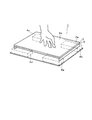
- FIG. 1 is a perspective view schematically showing the overall configuration of an embodiment.
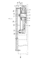
- FIG. 2 is a longitudinal side view showing the configuration of the actuator
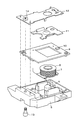
- FIG. 3 is an exploded perspective view showing components of the actuator
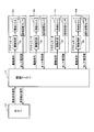
- FIG. 4 is a functional block diagram.
- FIG. 5 is a diagram showing the relationship between the actuator attractive force and spring reaction force and the yoke clearance distance
- FIG. 6 is a diagram showing the movement of the movable yoke
- FIG. 7 is a flowchart (part 1) showing the tactile sense presenting process.
- FIG. 8 is a flowchart (part 2) illustrating the tactile sense presenting process.
- the tactile sensation presentation system 1 includes a display 2 having a square display surface 2 a, a touch panel 3 (corresponding to a vibration target) covering the entire display surface 2 a, and four corners of the display 2 And four actuators 4a to 4d (corresponding to a tactile sensation presentation device) arranged below.
- the touch panel 3 is supported at four corners of the display 2 by four actuators 4a to 4d.
- the touch panel 3 is made of a transparent material so that the user can visually recognize icons and the like displayed on the display surface 2a, and the surface portion thereof is a touch surface 3a.
- the configuration in which the number of actuators is “4” is exemplified.
- the actuators You may increase the number. That is, any number of actuators may be designed as long as the display 2 and the touch panel 3 are supported uniformly.
- the four actuators 4a to 4d have the same configuration, and the actuator 4a will be described as a representative.
- the actuator 4a includes a case 5, a fixed yoke 6 disposed in a fixed state on the case 5, a bobbin 8 around which a winding coil 7 is wound, and a sensor circuit board. 9, a gap distance sensor 10 mounted on the sensor circuit board 9, a movable yoke 11 disposed above the fixed yoke 6, and a leaf spring 12 (corresponding to an elastic member).
- One end of the leaf spring 12 is fixed to the case 5 by a bolt 13 and a nut 14, and the movable yoke 11 is caulked and integrated at the other end.
- the four corners of the lower surface of the display 2 and the other end of the movable yoke 11 are connected via a stay 15. That is, the four corners of the lower surface portion of the display device 2 are suspended by the leaf spring 12, and the movable yoke 11 is connected to the touch panel 3 via the leaf spring 12.
- the leaf spring 12 is connected to the display device 2 via the stay 15, the display device 2 and the touch panel 3 integrally vibrate in the vertical direction, and the user touches the touch surface 3 a of the touch panel 3. In the state, the vertical vibration is presented as a tactile sensation.
- the gap distance sensor 10 is disposed below the movable yoke 11.
- the light emitting unit emits infrared light toward the lower surface of the movable yoke 11, and the emitted infrared light is reflected by the lower surface of the movable yoke 11. And a light receiving portion that receives the reflected light.
- the light receiving unit is a phototransistor, for example.
- the gap distance sensor 10 measures the amount of the received reflected light, converts it to a current value, and outputs the current value as a sensor current value.
- the tactile sensation presentation system 1 has a functional block shown in FIG. 4 as an electrical configuration.
- the tactile sensation presentation system 1 includes a host 16, a control microcomputer 17, and the four actuators 4a to 4d described above.
- the control microcomputer 17 has a CPU (Central Processing Unit), ROM (Read Only Memory), RAM (Random Access Memory), and I / O (Input / Output), and is stored in a non-transitional physical storage medium. By executing the computer program, processing corresponding to the computer program is executed, and the overall operation of the tactile sense presentation system 1 is controlled.
- CPU Central Processing Unit
- ROM Read Only Memory
- RAM Random Access Memory
- I / O Input / Output
- Each of the actuators 4a to 4d has a drive circuit 18 for passing a drive current through the winding coil 7 and a gap distance sensor 10.
- the gap distance sensor 10 measures the amount of reflected light according to the user's operation, converts it to a current value, and outputs the current value to the control microcomputer 17 as a sensor current value.
- the control microcomputer 17 identifies the actuators 4a to 4d by ID.
- the control microcomputer 17 specifies that the user has touched the touch surface 3a, and the sensor current values of the actuators 4a to 4d. Then, an operation detection signal that can specify the output source of the gap distance specified from the above is output to the host 16.
- the host 16 When an operation detection signal is input from the control microcomputer 17, the host 16 specifies a pressed position where the user touches the touch surface 3a by a touch panel controller (not shown), associates the specified pressed position with a display object, and how Decide whether to present a tactile sensation.
- the touch panel controller since the actuators 4a to 4d are arranged below the four corners of the display 2, the touch panel controller detects the displacement of the gap distance specified from the sensor current value output from each gap distance sensor 10.
- the pressing position where the user touches the touch surface 3a can be specified by proportionally allocating according to the arrangement of the actuators 4a to 4d.
- the host 16 determines the tactile sensation to be presented to the user, the host 16 outputs to the control microcomputer 17 a vibration command signal that can specify data defining the tactile presentation based on the determined tactile sense.
- control microcomputer 17 When the control microcomputer 17 receives a vibration command signal from the host 16, the control microcomputer 17 specifies data defining tactile presentation from the input vibration command signal.
- the control microcomputer 17 specifies a pressure detection value corresponding to the pressing force applied to the touch surface 3a when the user touches the touch surface 3a due to the displacement of the gap distance specified from the sensor current value input from the gap distance sensor 10.
- a drive signal corresponding to the specified data is output to the drive circuit 18. That is, the control microcomputer 17 provides a threshold value for each button switch area displayed on the touch panel 3, for example, and outputs a drive signal to the drive circuit 18 when the detected pressure value exceeds the threshold value.
- the threshold value distinguishes operations such as the user pressing the touch surface 3a lightly for a short time, lightly pressing for a long time, deeply pressing for a short time, and deeply pressing for a long time. It is a threshold for.
- a drive signal output from the control microcomputer 17 to the drive circuit 18 is a PWM signal.
- the detected pressure value is a total value of values obtained by multiplying the output change amount from the state where no pressing force is applied in each gap distance sensor 10 by a constant determined from the mechanical structure.
- the drive circuit 18 When the drive signal is input from the control microcomputer 17, the drive circuit 18 outputs a drive current specified by the input drive signal to the winding coil 7, generates a magnetic field around the winding coil 7, and generates the fixed yoke 6. An electromagnetic force is generated in the actuator to generate an actuator suction force.
- the yoke clearance distance is desirably 1 mm or less in order to effectively use the actuator suction force.
- the control microcomputer 17 needs to control the actuator suction force so that the movable yoke 11 does not collide with the fixed yoke 6. That is, the control microcomputer 17 needs to measure the yoke gap distance, feedback control the drive current flowing through the winding coil 7 using the measured yoke gap distance, and control the actuator attraction force.
- the relationship between the actuator suction force and spring reaction force (equivalent to the elastic force) and the yoke clearance distance has the characteristics shown in FIG.
- the solid line indicates the relationship between the actuator attractive force and the yoke clearance distance
- the broken line indicates the relationship between the spring reaction force and the yoke clearance distance.
- the spring reaction force is an elastic force generated with the displacement of the leaf spring 12 from the neutral state
- the neutral state is a state where no actuator suction force is generated.
- the actuator attractive force is inversely proportional to the yoke clearance distance and proportional to the square of the current flowing through the winding coil 7 in a range where no magnetic saturation of the electromagnet occurs.
- the actuator attractive force is “Fcoil”
- the magnet constant (equivalent to the electromagnetic force generation coefficient) is “M”
- the current value of the drive current flowing through the winding coil 7 is “i”
- the spring reaction force is proportional to the positional displacement from the neutral state of the leaf spring 12.
- the spring reaction force is “Fk”
- the spring constant is “K”
- the displacement is “ ⁇ L”
- Fk ⁇ K ⁇ ⁇ L
- Fcoil + Fk 0
- the movable yoke 11 when the drive current is less than the current value “i3”, the movable yoke 11 does not collide with the fixed yoke 6. However, when the drive current is greater than the current value “i3”, the movable yoke 11 collides with the fixed yoke 6. In other words, the maximum current value of the drive current at which the movable yoke 11 does not collide with the fixed yoke 6 is the current value “i3”.
- the gap distance sensor 10 when the reflected light is received by the light receiving unit, the gap distance sensor 10 measures the light amount of the received reflected light and converts it into a current value, and outputs the current value as a sensor current value to the control microcomputer 17. To do.
- the control microcomputer 17 inputs the sensor current value from the gap distance sensor 10, the input sensor current value is converted into a distance, and the vertical gap distance between the gap distance sensor 10 and the lower surface portion of the movable yoke 11 is calculated. It is specified as the sensor gap distance. In this case, the following relationship is established between the sensor gap distance and the yoke gap distance as described above.
- Sensor clearance distance yoke clearance distance + offset distance
- the yoke gap distance depends on the pressing force and the pressing position when the user touches the touch surface 3a. That is, if the user presses near the center of the touch surface 3a, the forces received by the actuators 4a to 4d are equal, but if the user presses the corner of the touch surface 3a, the user The movable yoke 11 bends downward in an actuator relatively close to the pressed portion, and the movable yoke 11 bends upward in an actuator relatively far from the portion pressed by the user.
- the yoke gap distance when presenting a tactile sensation will be described.
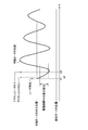
- the movement of the movable yoke 11 when presenting a tactile sensation exhibits characteristics as shown in FIG.
- FIG. 6 when the user touches the touch surface 3a (t1), the yoke gap distance is reduced by the pressing force from the user, and then when the drive current is started (t2), the actuator attractive force is generated. In addition, the yoke gap distance is further reduced.
- the actuator attractive force disappears, and the movable yoke 11 starts damped vibration according to the frequency determined by the spring constant of the leaf spring 12 and the mass of the movable yoke 11.
- FIG. 6 When the supply of the drive current is completed (t3), the actuator attractive force disappears, and the movable yoke 11 starts damped vibration according to the frequency determined by the spring constant of the leaf spring 12 and the mass of the movable yoke 11.
- the actuator driving period is a period during which a driving current is supplied.
- the yoke gap distance is sequentially specified, and the actuator is touched by correcting the drive current in accordance with the yoke gap distance that is sequentially specified by utilizing the fact that the actuator suction force is inversely proportional to the yoke gap distance. It is possible to reduce the influence of variations in the pressing position touching the surface 3a and the yoke gap distance.
- the electromagnet response time is generated with respect to the actuator driving period, and therefore it is difficult to sequentially specify the yoke gap distance and correct the driving current in the actuator driving period.
- the yoke gap distance is specified in advance from the current waveform data during the actuator drive period. Then, the neutral yoke clearance distance is compared with the reference value, and when the neutral yoke clearance distance is different from the reference value, the drive current command value for commanding the current value of the drive current is determined as the actual yoke clearance distance.
- the corrected drive current command value is specified, and the actuators 4a to 4d are driven according to the specified corrected drive current command value, so that the pressing position where the user touches the touch surface 3a In addition, the influence of variations in the yoke gap distance can be reduced.
- a state equation representing the relationship among the drive current command value, the actuator suction force, the spring reaction force, and the mass of the movable yoke 11 when the initial yoke gap distance is the neutral yoke gap distance is solved and corrected.
- the drive current command value may be specified and the drive current may be corrected.
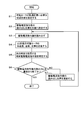
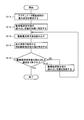
- FIGS. 7 and 8 show the tactile sense presenting process executed by the control microcomputer 17, respectively.
- the control microcomputer 17 to correct the current command value of the drive current: a first correction method and a second correction method. Hereinafter, each method will be described.
- the pushing force generated when the user touches the touch surface 3a is not easily affected by the change in the position of the movable yoke 11, so that it is considered that a constant spring displacement is always generated. Absent.
- the speed V (D1, t) of the movable yoke 11 after ⁇ t seconds can be specified from the previous speed + the acceleration of the movable yoke 11 ⁇ ⁇ t.
- the position P (D1, t) of the movable yoke 11 after ⁇ t seconds can be specified from the previous position + the speed of the movable yoke 11 ⁇ ⁇ t.
- the drive current at time t is P (D2, t) / P (D1, t) times.
- Force acting on movable yoke 11 in response to generation of actuator attraction force magnet constant M ⁇ drive current command value ⁇ 2 / P (D, t) ( ⁇ indicates power)
- Force acting on the movable yoke 11 according to the deformation of the leaf spring 12 ⁇ spring constant K ⁇ (P (D, t) ⁇ D)
- Standard value D1 center value of yoke gap distance at the time of design in the neutral state ⁇ pushing amount
- Standard value D2 actual yoke gap distance in the neutral state ⁇ pushing amount
- control microcomputer 17 sets the read position of the drive current command value stored in the drive waveform data to the top (S2).
- the control microcomputer 17 reads the drive current command value stored in the drive waveform data according to the set read position (S3).
- the control microcomputer 17 defines the acceleration, speed, and position of the movable yoke 11 after ⁇ t seconds as follows (S4).
- a (D1, t + ⁇ t) (M ⁇ drive current command value ⁇ 2 / P (D1, t) ⁇ K ⁇ (P (D1, t) ⁇ D1) / Mass ( ⁇ indicates power))
- a (D2, t + ⁇ t) (M ⁇ corrected driving current command value ⁇ 2 / P (D2, t) ⁇ K ⁇ (P (D2, t) ⁇ D2) / Mass ( ⁇ indicates a power))
- V (D2, t + ⁇ t) V (D2, t) + A (D2, t) ⁇ ⁇ t P
- the control microcomputer 17 specifies the correction drive current command value to be used at the next time as follows using the defined acceleration, speed, and position of the movable yoke 11 after ⁇ t seconds (S5).
- Corrected drive current command value P (D2, t) / P (D1, t) ⁇ drive current command value
- control microcomputer 17 determines whether or not the reading of the drive current command value has been completed to the end (S6). If the control microcomputer 17 determines that the reading of the drive current command value has not been completed (S6: NO), the control microcomputer 17 updates the read position of the drive current command value stored in the drive waveform data (S7). Returning to step S3, step S3 and subsequent steps are repeated. If the control microcomputer 17 determines that the reading of the drive current command value has been completed to the end (S6: YES), the tactile sense presenting process is terminated.
- the actuator attraction force in each actuator 4a to 4d can be balanced by controlling the drive current supplied to each actuator 4a to 4d according to the yoke gap distance.
- the second correction method is in a standard state in which there is no variation in the actuator suction force when the movable yoke 11 is at the center position and the standard gap distance, that is, assembly, etc. during the actuator driving period.
- the correction drive current command value is specified so that the actuator attracting force at that time becomes the same.
- the standard values D1 and D2 described above are defined as follows.
- Standard value D1 Gap distance design value in neutral state ⁇ Standard indentation amount
- Standard value D2 Gap distance estimated value in neutral state ⁇ Standard indentation amount
- Standard indentation amount is the amount of change in the gap that detects the pressure when the vibration waveform is generated. is there.
- the control microcomputer 17 specifies the maximum displacement VA during the actuator driving period (S11).
- control microcomputer 17 sets the read position of the drive current command value stored in the drive waveform data to the top (S12).
- the control microcomputer 17 reads the drive current command value stored in the drive waveform data according to the set read position (S13).
- control microcomputer 17 determines whether or not the reading of the drive current command value has been completed to the end (S15). If the control microcomputer 17 determines that the reading of the drive current command value has not been completed (S15: NO), the control microcomputer 17 updates the read position of the drive current command value stored in the drive waveform data (S16). Returning to step S3, step S3 and subsequent steps are repeated. When the control microcomputer 17 determines that the reading of the drive current command value has been completed to the end (S15: YES), the tactile sense presenting process is terminated.
- the first correction method is complicated in calculation, and if the drive waveform data is complicated, there is a problem that it is difficult to consider trajectory errors due to frictional forces and the like.
- the second correction method can be adopted.
- the drive current supplied to the actuators 4a to 4d is controlled according to the center position of the movable yoke 11, so that the actuators 4a to 4d are controlled in the same manner as in the first correction method.
- the actuator suction force can be balanced. Note that steps S1 to S7 of the first correction method and steps S11 to S16 of the second correction method correspond to control procedures.
- the current value of the drive current is adjusted to balance the actuator attractive force.
- the drive capability of the drive circuit 18 is insufficient, and if the corrected drive current command value is large, the corrected drive is performed.
- the drive current having the current value commanded by the current command value cannot be supplied to the actuators 4a to 4d. In that case, it is sufficient to adjust the energization time, which is the time width for supplying the drive current, to balance the actuator attractive force.
- the energization time may be 1 / X ⁇ 2 times.
- the control microcomputer 17 calculates ⁇ t, but when adjusting the energization time, it may be calculated as ⁇ t / X ⁇ 2.
- the configuration described above starts supplying the drive current after the user touches the touch surface 3a, reduces the influence of the pressing position where the user touches the touch surface 3a, and reduces the influence of the variation in the yoke gap distance.
- the drive current supply is started before the user touches the touch surface 3a, the influence of the variation in the yoke gap distance is reduced, and the user touches the touch surface 3a after touching the touch surface 3a.
- the drive current command value of the drive current is changed after the user touches the touch surface 3a, and the influence of the pressing position where the user touches the touch surface 3a is reduced.
- the offset force before the user touches the touch surface 3a is continuously generated even after the user touches the touch surface 3a.
- the current value or energization time of the drive current is individually controlled for each of the actuators 4a to 4d.
- the actuator suction force for each of the actuators 4a to 4d By individually controlling the actuator suction force for each of the actuators 4a to 4d, the influence of variations in the pressing position and yoke gap distance that the user touches the touch surface 3a is reduced, and the position displacement and acceleration of the movable yoke 11 are made constant. And a stable tactile sensation can be appropriately presented.
- the locus of the movable yoke 11 is specified, and the current value or energization time of the drive current is controlled using the specified locus of the movable yoke 11.
- a stable tactile sensation can be appropriately presented using the trajectory of the movable yoke 11.
- the yoke gap distance in the drive period is sequentially specified, and the current value or energization time of the drive current is controlled according to the specified yoke gap distance.
- the central position of the movable yoke 11 in the driving period is specified, and the current value or energization time of the driving current is controlled according to the specified central position of the movable yoke.
- Calculation can be simplified by omitting the process of sequentially specifying the yoke gap distance and using the center position of the movable yoke 11 during the driving period.
- the configuration is not limited to the configuration applied to the vehicle, but may be a configuration applied to other purposes.
- the processing performed by the control microcomputer 17 may be performed by the host 16, or the processing performed by the host 16 may be performed by the control microcomputer 17, and how the processing performed by the host 16 and the processing performed by the control microcomputer 17 is distributed. May be.
- the touch panel 3 is supported by a plurality of actuators 4a to 4d and the current value or the energization time of the drive current supplied to each actuator is individually controlled
- the control target may be one. .
- the present invention may be applied to a configuration in which the vibration target is supported by one actuator.
Landscapes
- Engineering & Computer Science (AREA)
- General Engineering & Computer Science (AREA)
- Theoretical Computer Science (AREA)
- Human Computer Interaction (AREA)
- Physics & Mathematics (AREA)
- General Physics & Mathematics (AREA)
- Power Engineering (AREA)
- Reciprocating, Oscillating Or Vibrating Motors (AREA)
- User Interface Of Digital Computer (AREA)
Abstract
L'invention concerne un système de présentation tactile (1) comprenant : une cible de vibration (3) comportant une surface tactile (3a) qui peut être pressée par un utilisateur ; un dispositif de présentation tactile (4) doté d'une culasse mobile (11) reliée à la cible de vibration par l'intermédiaire d'un élément élastique (12) et une culasse fixe (6) qui aspire la culasse mobile ; et une unité de commande (17) qui présente une sensation tactile par vibration de la cible de vibration par génération d'une force d'aspiration en fournissant un courant d'excitation au dispositif de présentation tactile. L'unité de commande commande la valeur actuelle et la durée du courant d'excitation séparément pour chaque dispositif de présentation tactile.
Applications Claiming Priority (2)
| Application Number | Priority Date | Filing Date | Title |
|---|---|---|---|
| JP2018018327A JP6888562B2 (ja) | 2018-02-05 | 2018-02-05 | 触覚呈示システム、コンピュータプログラム及び記憶媒体 |
| JP2018-018327 | 2018-02-05 |
Publications (1)
| Publication Number | Publication Date |
|---|---|
| WO2019150737A1 true WO2019150737A1 (fr) | 2019-08-08 |
Family
ID=67478977
Family Applications (1)
| Application Number | Title | Priority Date | Filing Date |
|---|---|---|---|
| PCT/JP2018/044002 Ceased WO2019150737A1 (fr) | 2018-02-05 | 2018-11-29 | Système de présentation tactile, programme informatique et support de stockage |
Country Status (2)
| Country | Link |
|---|---|
| JP (1) | JP6888562B2 (fr) |
| WO (1) | WO2019150737A1 (fr) |
Cited By (1)
| Publication number | Priority date | Publication date | Assignee | Title |
|---|---|---|---|---|
| EP3805901A1 (fr) * | 2019-10-09 | 2021-04-14 | Minebea Mitsumi Inc. | Dispositif de commande pour commander un actionneur electromagnetique |
Families Citing this family (2)
| Publication number | Priority date | Publication date | Assignee | Title |
|---|---|---|---|---|
| JP7370822B2 (ja) * | 2019-11-15 | 2023-10-30 | ミネベアミツミ株式会社 | 振動アクチュエータ及び振動呈示装置 |
| WO2024044890A1 (fr) * | 2022-08-29 | 2024-03-07 | 深圳纽迪瑞科技开发有限公司 | Module de rétroaction de vibration, appareil tactile, et dispositif électronique |
Citations (5)
| Publication number | Priority date | Publication date | Assignee | Title |
|---|---|---|---|---|
| JP2013050920A (ja) * | 2011-08-31 | 2013-03-14 | Minebea Co Ltd | 入力装置 |
| JP2015158912A (ja) * | 2006-10-04 | 2015-09-03 | イマージョン コーポレーションImmersion Corporation | 近接感知による触覚的効果 |
| JP2015203893A (ja) * | 2014-04-11 | 2015-11-16 | 株式会社日本自動車部品総合研究所 | タッチパネル式入力装置 |
| JP2017111462A (ja) * | 2015-11-27 | 2017-06-22 | 京セラ株式会社 | 触感呈示装置及び触感呈示方法 |
| JP2018005903A (ja) * | 2016-06-20 | 2018-01-11 | アップル インコーポレイテッド | 局在化された及び/又はカプセル化された触覚アクチュエータ及び要素 |
-
2018
- 2018-02-05 JP JP2018018327A patent/JP6888562B2/ja active Active
- 2018-11-29 WO PCT/JP2018/044002 patent/WO2019150737A1/fr not_active Ceased
Patent Citations (5)
| Publication number | Priority date | Publication date | Assignee | Title |
|---|---|---|---|---|
| JP2015158912A (ja) * | 2006-10-04 | 2015-09-03 | イマージョン コーポレーションImmersion Corporation | 近接感知による触覚的効果 |
| JP2013050920A (ja) * | 2011-08-31 | 2013-03-14 | Minebea Co Ltd | 入力装置 |
| JP2015203893A (ja) * | 2014-04-11 | 2015-11-16 | 株式会社日本自動車部品総合研究所 | タッチパネル式入力装置 |
| JP2017111462A (ja) * | 2015-11-27 | 2017-06-22 | 京セラ株式会社 | 触感呈示装置及び触感呈示方法 |
| JP2018005903A (ja) * | 2016-06-20 | 2018-01-11 | アップル インコーポレイテッド | 局在化された及び/又はカプセル化された触覚アクチュエータ及び要素 |
Cited By (3)
| Publication number | Priority date | Publication date | Assignee | Title |
|---|---|---|---|---|
| EP3805901A1 (fr) * | 2019-10-09 | 2021-04-14 | Minebea Mitsumi Inc. | Dispositif de commande pour commander un actionneur electromagnetique |
| US11728756B2 (en) | 2019-10-09 | 2023-08-15 | Minebea Mitsumi Inc. | Control device |
| US12224686B2 (en) | 2019-10-09 | 2025-02-11 | Minebea Mitsumi Inc. | Actuator |
Also Published As
| Publication number | Publication date |
|---|---|
| JP6888562B2 (ja) | 2021-06-16 |
| JP2019135606A (ja) | 2019-08-15 |
Similar Documents
| Publication | Publication Date | Title |
|---|---|---|
| KR102608389B1 (ko) | 버튼형 액추에이터, 이를 포함하는 버튼형 액추에이터 피드백 시스템 및 그 제어 방법 | |
| US10232714B2 (en) | Motor vehicle operating device with controller to provide bounce suppression for actuating element | |
| JP7669626B2 (ja) | アクチュエーター | |
| CN108475106B (zh) | 触摸界面模块和用于生成触觉反馈的方法 | |
| US9891708B2 (en) | Method and apparatus for generating haptic effects using actuators | |
| WO2019150737A1 (fr) | Système de présentation tactile, programme informatique et support de stockage | |
| KR102568811B1 (ko) | 장치를 위한 조작 유닛 | |
| JP2017027731A (ja) | 操作装置 | |
| JP2019101524A (ja) | 触覚出力装置 | |
| JP6528014B1 (ja) | 触感発生装置および触感発生方法 | |
| JP2019153272A (ja) | 入力装置 | |
| WO2022014135A1 (fr) | Système de véhicule et dispositif de génération de vibrations | |
| JP2017004262A (ja) | 操作装置 | |
| JP2022056147A (ja) | 振動アクチュエーター及び振動呈示装置 | |
| CN112384885A (zh) | 发生模拟触感的按键输入装置 | |
| JP2018045407A (ja) | 触覚呈示装置 | |
| JP7274609B2 (ja) | 操作装置 | |
| JP7306257B2 (ja) | 操作装置 | |
| EP3557382A1 (fr) | Dispositif de génération de force réactive et unité d'affichage embarquée dans un véhicule comprenant le dispositif de génération de force réactive | |
| JP2022056149A (ja) | 振動アクチュエーター及び振動呈示装置 | |
| KR102836011B1 (ko) | 입력 장치 | |
| JP6852664B2 (ja) | 触覚呈示装置、触覚呈示システム、コンピュータプログラム及び記憶媒体 | |
| JP2020071674A (ja) | 触覚呈示装置 | |
| JP7154379B2 (ja) | 電磁駆動装置及び操作装置 | |
| JP7344057B2 (ja) | 制御装置、制御方法、及びプログラム |
Legal Events
| Date | Code | Title | Description |
|---|---|---|---|
| 121 | Ep: the epo has been informed by wipo that ep was designated in this application |
Ref document number: 18904018 Country of ref document: EP Kind code of ref document: A1 |
|
| NENP | Non-entry into the national phase |
Ref country code: DE |
|
| 122 | Ep: pct application non-entry in european phase |
Ref document number: 18904018 Country of ref document: EP Kind code of ref document: A1 |