WO2019150737A1 - Tactile presentation system, computer program and storage medium - Google Patents
Tactile presentation system, computer program and storage medium Download PDFInfo
- Publication number
- WO2019150737A1 WO2019150737A1 PCT/JP2018/044002 JP2018044002W WO2019150737A1 WO 2019150737 A1 WO2019150737 A1 WO 2019150737A1 JP 2018044002 W JP2018044002 W JP 2018044002W WO 2019150737 A1 WO2019150737 A1 WO 2019150737A1
- Authority
- WO
- WIPO (PCT)
- Prior art keywords
- yoke
- drive current
- movable yoke
- gap distance
- tactile
- Prior art date
- Legal status (The legal status is an assumption and is not a legal conclusion. Google has not performed a legal analysis and makes no representation as to the accuracy of the status listed.)
- Ceased
Links
Images

Classifications
-
- G—PHYSICS
- G06—COMPUTING OR CALCULATING; COUNTING
- G06F—ELECTRIC DIGITAL DATA PROCESSING
- G06F3/00—Input arrangements for transferring data to be processed into a form capable of being handled by the computer; Output arrangements for transferring data from processing unit to output unit, e.g. interface arrangements
- G06F3/01—Input arrangements or combined input and output arrangements for interaction between user and computer
- G06F3/016—Input arrangements with force or tactile feedback as computer generated output to the user
-
- G—PHYSICS
- G06—COMPUTING OR CALCULATING; COUNTING
- G06F—ELECTRIC DIGITAL DATA PROCESSING
- G06F3/00—Input arrangements for transferring data to be processed into a form capable of being handled by the computer; Output arrangements for transferring data from processing unit to output unit, e.g. interface arrangements
- G06F3/01—Input arrangements or combined input and output arrangements for interaction between user and computer
- G06F3/03—Arrangements for converting the position or the displacement of a member into a coded form
- G06F3/041—Digitisers, e.g. for touch screens or touch pads, characterised by the transducing means
-
- H—ELECTRICITY
- H02—GENERATION; CONVERSION OR DISTRIBUTION OF ELECTRIC POWER
- H02K—DYNAMO-ELECTRIC MACHINES
- H02K33/00—Motors with reciprocating, oscillating or vibrating magnet, armature or coil system
- H02K33/02—Motors with reciprocating, oscillating or vibrating magnet, armature or coil system with armatures moved one way by energisation of a single coil system and returned by mechanical force, e.g. by springs
Definitions
- the present disclosure relates to a tactile presentation system, a computer program, and a storage medium.
- a configuration is provided in which a tactile sensation is presented when the user touches the touch surface of the touch panel.
- a frequency at which a person can easily detect a tactile sense is about several tens of Hz.
- a configuration for generating vibrations of about several tens of Hz a configuration is disclosed in which a vibrating body is disposed below a vibrating target that is a target to be vibrated, the vibration of the vibrating body is propagated to the vibrating target, and the vibrating target is vibrated indirectly (For example, refer to Patent Document 1).
- the actuator suction force that sucks the movable yoke is significantly affected by the yoke gap distance that is the gap distance in the suction direction between the fixed yoke and the movable yoke, thus reducing the influence of the yoke gap distance.
- the yoke gap distance that is the gap distance in the suction direction between the fixed yoke and the movable yoke, thus reducing the influence of the yoke gap distance.
- the yoke gap distance of each actuator depends on the pressing force and the pressing position when the user touches the touch surface. In this case, unless correction is performed individually according to each yoke gap distance, even if the current value of the drive current supplied to each actuator is the same, if the yoke gap distance is relatively small, the actuator attraction force is relatively If the yoke gap distance is relatively large, the actuator attractive force becomes relatively small. Therefore, the position displacement and acceleration of the movable yoke of each actuator become non-uniform, the touch panel is pulled non-uniformly by the actuator, and the touch panel tilts. In order to appropriately present a tactile sensation when the user touches the touch surface, there is a mechanism that makes the displacement and acceleration of the movable yoke constant regardless of variations in the pressing position and yoke gap distance where the user touches the touch surface. is necessary.
- the present disclosure can make the positional displacement and acceleration of the movable yoke constant by reducing the influence of variations in the pressing position where the user touches the touch surface and the yoke gap distance, and appropriately presents a stable tactile sensation. It is an object to provide a tactile sensation presentation system, a computer program, and a storage medium.
- the vibration target has a touch surface that can be pressed by the user.
- the tactile sensation presentation apparatus has a movable yoke connected to a vibration target via an elastic member and a fixed yoke that sucks the movable yoke.
- the control unit generates a suction force by supplying a drive current to the tactile sensation presentation device, thereby vibrating the vibration target and presenting the haptic sense.
- the control unit individually controls the current value or energization time of the drive current for each tactile sensation presentation apparatus.
- the suction force generated by the tactile presentation device can be individually controlled for each tactile presentation device.
- the positional displacement and acceleration of the movable yoke can be made constant by reducing the influence of the variation of the pressing position where the user touches the touch surface and the yoke gap distance, and a stable tactile sensation can be appropriately presented. Can do.
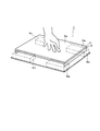
- FIG. 1 is a perspective view schematically showing the overall configuration of an embodiment.
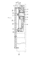
- FIG. 2 is a longitudinal side view showing the configuration of the actuator
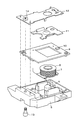
- FIG. 3 is an exploded perspective view showing components of the actuator
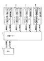
- FIG. 4 is a functional block diagram.
- FIG. 5 is a diagram showing the relationship between the actuator attractive force and spring reaction force and the yoke clearance distance
- FIG. 6 is a diagram showing the movement of the movable yoke
- FIG. 7 is a flowchart (part 1) showing the tactile sense presenting process.
- FIG. 8 is a flowchart (part 2) illustrating the tactile sense presenting process.
- the tactile sensation presentation system 1 includes a display 2 having a square display surface 2 a, a touch panel 3 (corresponding to a vibration target) covering the entire display surface 2 a, and four corners of the display 2 And four actuators 4a to 4d (corresponding to a tactile sensation presentation device) arranged below.
- the touch panel 3 is supported at four corners of the display 2 by four actuators 4a to 4d.
- the touch panel 3 is made of a transparent material so that the user can visually recognize icons and the like displayed on the display surface 2a, and the surface portion thereof is a touch surface 3a.
- the configuration in which the number of actuators is “4” is exemplified.
- the actuators You may increase the number. That is, any number of actuators may be designed as long as the display 2 and the touch panel 3 are supported uniformly.
- the four actuators 4a to 4d have the same configuration, and the actuator 4a will be described as a representative.
- the actuator 4a includes a case 5, a fixed yoke 6 disposed in a fixed state on the case 5, a bobbin 8 around which a winding coil 7 is wound, and a sensor circuit board. 9, a gap distance sensor 10 mounted on the sensor circuit board 9, a movable yoke 11 disposed above the fixed yoke 6, and a leaf spring 12 (corresponding to an elastic member).
- One end of the leaf spring 12 is fixed to the case 5 by a bolt 13 and a nut 14, and the movable yoke 11 is caulked and integrated at the other end.
- the four corners of the lower surface of the display 2 and the other end of the movable yoke 11 are connected via a stay 15. That is, the four corners of the lower surface portion of the display device 2 are suspended by the leaf spring 12, and the movable yoke 11 is connected to the touch panel 3 via the leaf spring 12.
- the leaf spring 12 is connected to the display device 2 via the stay 15, the display device 2 and the touch panel 3 integrally vibrate in the vertical direction, and the user touches the touch surface 3 a of the touch panel 3. In the state, the vertical vibration is presented as a tactile sensation.
- the gap distance sensor 10 is disposed below the movable yoke 11.
- the light emitting unit emits infrared light toward the lower surface of the movable yoke 11, and the emitted infrared light is reflected by the lower surface of the movable yoke 11. And a light receiving portion that receives the reflected light.
- the light receiving unit is a phototransistor, for example.
- the gap distance sensor 10 measures the amount of the received reflected light, converts it to a current value, and outputs the current value as a sensor current value.
- the tactile sensation presentation system 1 has a functional block shown in FIG. 4 as an electrical configuration.
- the tactile sensation presentation system 1 includes a host 16, a control microcomputer 17, and the four actuators 4a to 4d described above.
- the control microcomputer 17 has a CPU (Central Processing Unit), ROM (Read Only Memory), RAM (Random Access Memory), and I / O (Input / Output), and is stored in a non-transitional physical storage medium. By executing the computer program, processing corresponding to the computer program is executed, and the overall operation of the tactile sense presentation system 1 is controlled.
- CPU Central Processing Unit
- ROM Read Only Memory
- RAM Random Access Memory
- I / O Input / Output
- Each of the actuators 4a to 4d has a drive circuit 18 for passing a drive current through the winding coil 7 and a gap distance sensor 10.
- the gap distance sensor 10 measures the amount of reflected light according to the user's operation, converts it to a current value, and outputs the current value to the control microcomputer 17 as a sensor current value.
- the control microcomputer 17 identifies the actuators 4a to 4d by ID.
- the control microcomputer 17 specifies that the user has touched the touch surface 3a, and the sensor current values of the actuators 4a to 4d. Then, an operation detection signal that can specify the output source of the gap distance specified from the above is output to the host 16.
- the host 16 When an operation detection signal is input from the control microcomputer 17, the host 16 specifies a pressed position where the user touches the touch surface 3a by a touch panel controller (not shown), associates the specified pressed position with a display object, and how Decide whether to present a tactile sensation.
- the touch panel controller since the actuators 4a to 4d are arranged below the four corners of the display 2, the touch panel controller detects the displacement of the gap distance specified from the sensor current value output from each gap distance sensor 10.
- the pressing position where the user touches the touch surface 3a can be specified by proportionally allocating according to the arrangement of the actuators 4a to 4d.
- the host 16 determines the tactile sensation to be presented to the user, the host 16 outputs to the control microcomputer 17 a vibration command signal that can specify data defining the tactile presentation based on the determined tactile sense.
- control microcomputer 17 When the control microcomputer 17 receives a vibration command signal from the host 16, the control microcomputer 17 specifies data defining tactile presentation from the input vibration command signal.
- the control microcomputer 17 specifies a pressure detection value corresponding to the pressing force applied to the touch surface 3a when the user touches the touch surface 3a due to the displacement of the gap distance specified from the sensor current value input from the gap distance sensor 10.
- a drive signal corresponding to the specified data is output to the drive circuit 18. That is, the control microcomputer 17 provides a threshold value for each button switch area displayed on the touch panel 3, for example, and outputs a drive signal to the drive circuit 18 when the detected pressure value exceeds the threshold value.
- the threshold value distinguishes operations such as the user pressing the touch surface 3a lightly for a short time, lightly pressing for a long time, deeply pressing for a short time, and deeply pressing for a long time. It is a threshold for.
- a drive signal output from the control microcomputer 17 to the drive circuit 18 is a PWM signal.
- the detected pressure value is a total value of values obtained by multiplying the output change amount from the state where no pressing force is applied in each gap distance sensor 10 by a constant determined from the mechanical structure.
- the drive circuit 18 When the drive signal is input from the control microcomputer 17, the drive circuit 18 outputs a drive current specified by the input drive signal to the winding coil 7, generates a magnetic field around the winding coil 7, and generates the fixed yoke 6. An electromagnetic force is generated in the actuator to generate an actuator suction force.
- the yoke clearance distance is desirably 1 mm or less in order to effectively use the actuator suction force.
- the control microcomputer 17 needs to control the actuator suction force so that the movable yoke 11 does not collide with the fixed yoke 6. That is, the control microcomputer 17 needs to measure the yoke gap distance, feedback control the drive current flowing through the winding coil 7 using the measured yoke gap distance, and control the actuator attraction force.
- the relationship between the actuator suction force and spring reaction force (equivalent to the elastic force) and the yoke clearance distance has the characteristics shown in FIG.
- the solid line indicates the relationship between the actuator attractive force and the yoke clearance distance
- the broken line indicates the relationship between the spring reaction force and the yoke clearance distance.
- the spring reaction force is an elastic force generated with the displacement of the leaf spring 12 from the neutral state
- the neutral state is a state where no actuator suction force is generated.
- the actuator attractive force is inversely proportional to the yoke clearance distance and proportional to the square of the current flowing through the winding coil 7 in a range where no magnetic saturation of the electromagnet occurs.
- the actuator attractive force is “Fcoil”
- the magnet constant (equivalent to the electromagnetic force generation coefficient) is “M”
- the current value of the drive current flowing through the winding coil 7 is “i”
- the spring reaction force is proportional to the positional displacement from the neutral state of the leaf spring 12.
- the spring reaction force is “Fk”
- the spring constant is “K”
- the displacement is “ ⁇ L”
- Fk ⁇ K ⁇ ⁇ L
- Fcoil + Fk 0
- the movable yoke 11 when the drive current is less than the current value “i3”, the movable yoke 11 does not collide with the fixed yoke 6. However, when the drive current is greater than the current value “i3”, the movable yoke 11 collides with the fixed yoke 6. In other words, the maximum current value of the drive current at which the movable yoke 11 does not collide with the fixed yoke 6 is the current value “i3”.
- the gap distance sensor 10 when the reflected light is received by the light receiving unit, the gap distance sensor 10 measures the light amount of the received reflected light and converts it into a current value, and outputs the current value as a sensor current value to the control microcomputer 17. To do.
- the control microcomputer 17 inputs the sensor current value from the gap distance sensor 10, the input sensor current value is converted into a distance, and the vertical gap distance between the gap distance sensor 10 and the lower surface portion of the movable yoke 11 is calculated. It is specified as the sensor gap distance. In this case, the following relationship is established between the sensor gap distance and the yoke gap distance as described above.
- Sensor clearance distance yoke clearance distance + offset distance
- the yoke gap distance depends on the pressing force and the pressing position when the user touches the touch surface 3a. That is, if the user presses near the center of the touch surface 3a, the forces received by the actuators 4a to 4d are equal, but if the user presses the corner of the touch surface 3a, the user The movable yoke 11 bends downward in an actuator relatively close to the pressed portion, and the movable yoke 11 bends upward in an actuator relatively far from the portion pressed by the user.
- the yoke gap distance when presenting a tactile sensation will be described.
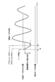
- the movement of the movable yoke 11 when presenting a tactile sensation exhibits characteristics as shown in FIG.
- FIG. 6 when the user touches the touch surface 3a (t1), the yoke gap distance is reduced by the pressing force from the user, and then when the drive current is started (t2), the actuator attractive force is generated. In addition, the yoke gap distance is further reduced.
- the actuator attractive force disappears, and the movable yoke 11 starts damped vibration according to the frequency determined by the spring constant of the leaf spring 12 and the mass of the movable yoke 11.
- FIG. 6 When the supply of the drive current is completed (t3), the actuator attractive force disappears, and the movable yoke 11 starts damped vibration according to the frequency determined by the spring constant of the leaf spring 12 and the mass of the movable yoke 11.
- the actuator driving period is a period during which a driving current is supplied.
- the yoke gap distance is sequentially specified, and the actuator is touched by correcting the drive current in accordance with the yoke gap distance that is sequentially specified by utilizing the fact that the actuator suction force is inversely proportional to the yoke gap distance. It is possible to reduce the influence of variations in the pressing position touching the surface 3a and the yoke gap distance.
- the electromagnet response time is generated with respect to the actuator driving period, and therefore it is difficult to sequentially specify the yoke gap distance and correct the driving current in the actuator driving period.
- the yoke gap distance is specified in advance from the current waveform data during the actuator drive period. Then, the neutral yoke clearance distance is compared with the reference value, and when the neutral yoke clearance distance is different from the reference value, the drive current command value for commanding the current value of the drive current is determined as the actual yoke clearance distance.
- the corrected drive current command value is specified, and the actuators 4a to 4d are driven according to the specified corrected drive current command value, so that the pressing position where the user touches the touch surface 3a In addition, the influence of variations in the yoke gap distance can be reduced.
- a state equation representing the relationship among the drive current command value, the actuator suction force, the spring reaction force, and the mass of the movable yoke 11 when the initial yoke gap distance is the neutral yoke gap distance is solved and corrected.
- the drive current command value may be specified and the drive current may be corrected.
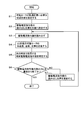
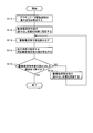
- FIGS. 7 and 8 show the tactile sense presenting process executed by the control microcomputer 17, respectively.
- the control microcomputer 17 to correct the current command value of the drive current: a first correction method and a second correction method. Hereinafter, each method will be described.
- the pushing force generated when the user touches the touch surface 3a is not easily affected by the change in the position of the movable yoke 11, so that it is considered that a constant spring displacement is always generated. Absent.
- the speed V (D1, t) of the movable yoke 11 after ⁇ t seconds can be specified from the previous speed + the acceleration of the movable yoke 11 ⁇ ⁇ t.
- the position P (D1, t) of the movable yoke 11 after ⁇ t seconds can be specified from the previous position + the speed of the movable yoke 11 ⁇ ⁇ t.
- the drive current at time t is P (D2, t) / P (D1, t) times.
- Force acting on movable yoke 11 in response to generation of actuator attraction force magnet constant M ⁇ drive current command value ⁇ 2 / P (D, t) ( ⁇ indicates power)
- Force acting on the movable yoke 11 according to the deformation of the leaf spring 12 ⁇ spring constant K ⁇ (P (D, t) ⁇ D)
- Standard value D1 center value of yoke gap distance at the time of design in the neutral state ⁇ pushing amount
- Standard value D2 actual yoke gap distance in the neutral state ⁇ pushing amount
- control microcomputer 17 sets the read position of the drive current command value stored in the drive waveform data to the top (S2).
- the control microcomputer 17 reads the drive current command value stored in the drive waveform data according to the set read position (S3).
- the control microcomputer 17 defines the acceleration, speed, and position of the movable yoke 11 after ⁇ t seconds as follows (S4).
- a (D1, t + ⁇ t) (M ⁇ drive current command value ⁇ 2 / P (D1, t) ⁇ K ⁇ (P (D1, t) ⁇ D1) / Mass ( ⁇ indicates power))
- a (D2, t + ⁇ t) (M ⁇ corrected driving current command value ⁇ 2 / P (D2, t) ⁇ K ⁇ (P (D2, t) ⁇ D2) / Mass ( ⁇ indicates a power))
- V (D2, t + ⁇ t) V (D2, t) + A (D2, t) ⁇ ⁇ t P
- the control microcomputer 17 specifies the correction drive current command value to be used at the next time as follows using the defined acceleration, speed, and position of the movable yoke 11 after ⁇ t seconds (S5).
- Corrected drive current command value P (D2, t) / P (D1, t) ⁇ drive current command value
- control microcomputer 17 determines whether or not the reading of the drive current command value has been completed to the end (S6). If the control microcomputer 17 determines that the reading of the drive current command value has not been completed (S6: NO), the control microcomputer 17 updates the read position of the drive current command value stored in the drive waveform data (S7). Returning to step S3, step S3 and subsequent steps are repeated. If the control microcomputer 17 determines that the reading of the drive current command value has been completed to the end (S6: YES), the tactile sense presenting process is terminated.
- the actuator attraction force in each actuator 4a to 4d can be balanced by controlling the drive current supplied to each actuator 4a to 4d according to the yoke gap distance.
- the second correction method is in a standard state in which there is no variation in the actuator suction force when the movable yoke 11 is at the center position and the standard gap distance, that is, assembly, etc. during the actuator driving period.
- the correction drive current command value is specified so that the actuator attracting force at that time becomes the same.
- the standard values D1 and D2 described above are defined as follows.
- Standard value D1 Gap distance design value in neutral state ⁇ Standard indentation amount
- Standard value D2 Gap distance estimated value in neutral state ⁇ Standard indentation amount
- Standard indentation amount is the amount of change in the gap that detects the pressure when the vibration waveform is generated. is there.
- the control microcomputer 17 specifies the maximum displacement VA during the actuator driving period (S11).
- control microcomputer 17 sets the read position of the drive current command value stored in the drive waveform data to the top (S12).
- the control microcomputer 17 reads the drive current command value stored in the drive waveform data according to the set read position (S13).
- control microcomputer 17 determines whether or not the reading of the drive current command value has been completed to the end (S15). If the control microcomputer 17 determines that the reading of the drive current command value has not been completed (S15: NO), the control microcomputer 17 updates the read position of the drive current command value stored in the drive waveform data (S16). Returning to step S3, step S3 and subsequent steps are repeated. When the control microcomputer 17 determines that the reading of the drive current command value has been completed to the end (S15: YES), the tactile sense presenting process is terminated.
- the first correction method is complicated in calculation, and if the drive waveform data is complicated, there is a problem that it is difficult to consider trajectory errors due to frictional forces and the like.
- the second correction method can be adopted.
- the drive current supplied to the actuators 4a to 4d is controlled according to the center position of the movable yoke 11, so that the actuators 4a to 4d are controlled in the same manner as in the first correction method.
- the actuator suction force can be balanced. Note that steps S1 to S7 of the first correction method and steps S11 to S16 of the second correction method correspond to control procedures.
- the current value of the drive current is adjusted to balance the actuator attractive force.
- the drive capability of the drive circuit 18 is insufficient, and if the corrected drive current command value is large, the corrected drive is performed.
- the drive current having the current value commanded by the current command value cannot be supplied to the actuators 4a to 4d. In that case, it is sufficient to adjust the energization time, which is the time width for supplying the drive current, to balance the actuator attractive force.
- the energization time may be 1 / X ⁇ 2 times.
- the control microcomputer 17 calculates ⁇ t, but when adjusting the energization time, it may be calculated as ⁇ t / X ⁇ 2.
- the configuration described above starts supplying the drive current after the user touches the touch surface 3a, reduces the influence of the pressing position where the user touches the touch surface 3a, and reduces the influence of the variation in the yoke gap distance.
- the drive current supply is started before the user touches the touch surface 3a, the influence of the variation in the yoke gap distance is reduced, and the user touches the touch surface 3a after touching the touch surface 3a.
- the drive current command value of the drive current is changed after the user touches the touch surface 3a, and the influence of the pressing position where the user touches the touch surface 3a is reduced.
- the offset force before the user touches the touch surface 3a is continuously generated even after the user touches the touch surface 3a.
- the current value or energization time of the drive current is individually controlled for each of the actuators 4a to 4d.
- the actuator suction force for each of the actuators 4a to 4d By individually controlling the actuator suction force for each of the actuators 4a to 4d, the influence of variations in the pressing position and yoke gap distance that the user touches the touch surface 3a is reduced, and the position displacement and acceleration of the movable yoke 11 are made constant. And a stable tactile sensation can be appropriately presented.
- the locus of the movable yoke 11 is specified, and the current value or energization time of the drive current is controlled using the specified locus of the movable yoke 11.
- a stable tactile sensation can be appropriately presented using the trajectory of the movable yoke 11.
- the yoke gap distance in the drive period is sequentially specified, and the current value or energization time of the drive current is controlled according to the specified yoke gap distance.
- the central position of the movable yoke 11 in the driving period is specified, and the current value or energization time of the driving current is controlled according to the specified central position of the movable yoke.
- Calculation can be simplified by omitting the process of sequentially specifying the yoke gap distance and using the center position of the movable yoke 11 during the driving period.
- the configuration is not limited to the configuration applied to the vehicle, but may be a configuration applied to other purposes.
- the processing performed by the control microcomputer 17 may be performed by the host 16, or the processing performed by the host 16 may be performed by the control microcomputer 17, and how the processing performed by the host 16 and the processing performed by the control microcomputer 17 is distributed. May be.
- the touch panel 3 is supported by a plurality of actuators 4a to 4d and the current value or the energization time of the drive current supplied to each actuator is individually controlled
- the control target may be one. .
- the present invention may be applied to a configuration in which the vibration target is supported by one actuator.
Landscapes
- Engineering & Computer Science (AREA)
- General Engineering & Computer Science (AREA)
- Theoretical Computer Science (AREA)
- Human Computer Interaction (AREA)
- Physics & Mathematics (AREA)
- General Physics & Mathematics (AREA)
- Power Engineering (AREA)
- Reciprocating, Oscillating Or Vibrating Motors (AREA)
- User Interface Of Digital Computer (AREA)
Abstract
Description
本出願は、2018年2月5日に出願された日本出願番号2018-018327号に基づくもので、ここにその記載内容を援用する。 This application is based on Japanese Application No. 2018-018327 filed on Feb. 5, 2018, the contents of which are incorporated herein by reference.
本開示は、触覚呈示システム、コンピュータプログラム及び記憶媒体に関する。 The present disclosure relates to a tactile presentation system, a computer program, and a storage medium.
ユーザがタッチパネルのタッチ面に触れたときに触覚を呈示する構成が供されている。触覚を呈示する構成において人が触覚を検出しやすい周波数は数十Hz程度である。数十Hz程度の振動を発生させる構成として、振動させる対象である振動対象の下方に振動体を配置し、振動体の振動を振動対象に伝搬させ、振動対象を間接的に振動させる構成が開示されている(例えば特許文献1参照)。 A configuration is provided in which a tactile sensation is presented when the user touches the touch surface of the touch panel. In a configuration that presents a tactile sense, a frequency at which a person can easily detect a tactile sense is about several tens of Hz. As a configuration for generating vibrations of about several tens of Hz, a configuration is disclosed in which a vibrating body is disposed below a vibrating target that is a target to be vibrated, the vibration of the vibrating body is propagated to the vibrating target, and the vibrating target is vibrated indirectly (For example, refer to Patent Document 1).
上記した特許文献1の構成では、共振を利用して振動対象を間接的に振動させる構成であるので、急峻な振動の立ち上がり特性を実現することができず、触覚を適切に呈示することができない問題がある。急峻な振動の立ち上がり特性を実現するには、共振を利用せずに振動対象を直接的に振動させる必要がある。振動対象を直接的に振動させる構成としては、アクチュエータを用いて振動対象を振動させる構成が考えられる。具体的には、タッチパネルを振動対象とする構成であれば、タッチパネルを板バネにより懸架して可動ヨークに接続し、固定ヨークに電磁力を発生させ、可動ヨークを吸引する構成が考えられる。
In the configuration of
このような構成では、可動ヨークを吸引するアクチュエータ吸引力が、固定ヨークと可動ヨークとの間の吸引方向の隙間距離であるヨーク隙間距離の影響を顕著に受けるので、ヨーク隙間距離の影響を軽減する必要がある。タッチパネルをアクチュエータにより複数箇所で板バネにより懸架する構成では、組み付け時に個体差によるヨーク隙間距離のばらつきが生じる。又、使用期間が長くなると経年変化による板バネのへたりによりヨーク隙間距離のばらつきが生じる可能性もある。 In such a configuration, the actuator suction force that sucks the movable yoke is significantly affected by the yoke gap distance that is the gap distance in the suction direction between the fixed yoke and the movable yoke, thus reducing the influence of the yoke gap distance. There is a need to. In a configuration in which the touch panel is suspended by a plate spring at a plurality of positions by an actuator, variations in yoke gap distance due to individual differences occur during assembly. Further, when the service period is extended, the yoke gap distance may vary due to the sag of the leaf spring due to aging.
タッチパネルをアクチュエータにより支持する構成では、各アクチュエータのヨーク隙間距離はユーザがタッチ面に触れたときの押圧力と押圧位置に依存する。この場合、各ヨーク隙間距離に応じて個別に補正を行わないと、各アクチュエータに供給する駆動電流の電流値が同じであっても、ヨーク隙間距離が相対的に小さければアクチュエータ吸引力は相対的に大きくなり、ヨーク隙間距離が相対的に大きければアクチュエータ吸引力は相対的に小さくなる。そのため、各アクチュエータの可動ヨークの位置変位及び加速度が不均一になり、タッチパネルがアクチュエータにより不均一に引っ張られ、タッチパネルが傾いてしまう。ユーザがタッチ面に触れたときに触覚を適切に呈示するには、ユーザがタッチ面に触れた押圧位置及びヨーク隙間距離のばらつきによらず、可動ヨークの位置変位及び加速度を一定にする仕組みが必要である。 In the configuration in which the touch panel is supported by the actuator, the yoke gap distance of each actuator depends on the pressing force and the pressing position when the user touches the touch surface. In this case, unless correction is performed individually according to each yoke gap distance, even if the current value of the drive current supplied to each actuator is the same, if the yoke gap distance is relatively small, the actuator attraction force is relatively If the yoke gap distance is relatively large, the actuator attractive force becomes relatively small. Therefore, the position displacement and acceleration of the movable yoke of each actuator become non-uniform, the touch panel is pulled non-uniformly by the actuator, and the touch panel tilts. In order to appropriately present a tactile sensation when the user touches the touch surface, there is a mechanism that makes the displacement and acceleration of the movable yoke constant regardless of variations in the pressing position and yoke gap distance where the user touches the touch surface. is necessary.
本開示は、ユーザがタッチ面に触れた押圧位置及びヨーク隙間距離のばらつきの影響を軽減することで、可動ヨークの位置変位及び加速度を一定にすることができ、安定した触覚を適切に呈示することができる触覚呈示システム、コンピュータプログラム及び記憶媒体を提供することを目的とする。 The present disclosure can make the positional displacement and acceleration of the movable yoke constant by reducing the influence of variations in the pressing position where the user touches the touch surface and the yoke gap distance, and appropriately presents a stable tactile sensation. It is an object to provide a tactile sensation presentation system, a computer program, and a storage medium.
本開示の一態様によれば、振動対象は、ユーザが押圧可能なタッチ面を有する。触覚呈示装置は、振動対象に対して弾性部材を介して接続されている可動ヨーク及び可動ヨークを吸引する固定ヨークを有する。制御部は、駆動電流を触覚呈示装置に供給して吸引力を発生させることで、振動対象を振動させて触覚を呈示する。制御部は、駆動電流の電流値又は通電時間を触覚呈示装置毎に個別に制御する。 According to one aspect of the present disclosure, the vibration target has a touch surface that can be pressed by the user. The tactile sensation presentation apparatus has a movable yoke connected to a vibration target via an elastic member and a fixed yoke that sucks the movable yoke. The control unit generates a suction force by supplying a drive current to the tactile sensation presentation device, thereby vibrating the vibration target and presenting the haptic sense. The control unit individually controls the current value or energization time of the drive current for each tactile sensation presentation apparatus.
駆動電流の電流値又は通電時間を触覚呈示装置毎に個別に制御することで、触覚呈示装置が発生する吸引力を触覚呈示装置毎に個別に制御することができる。これにより、ユーザがタッチ面に触れた押圧位置及びヨーク隙間距離のばらつきの影響を軽減することで、可動ヨークの位置変位及び加速度を一定にすることができ、安定した触覚を適切に呈示することができる。 By individually controlling the current value or energization time of the drive current for each tactile presentation device, the suction force generated by the tactile presentation device can be individually controlled for each tactile presentation device. As a result, the positional displacement and acceleration of the movable yoke can be made constant by reducing the influence of the variation of the pressing position where the user touches the touch surface and the yoke gap distance, and a stable tactile sensation can be appropriately presented. Can do.
本開示についての上記目的及びその他の目的、特徴や利点は、添付の図面を参照しながら下記の詳細な記述により、より明確になる。その図面は、
以下、一実施形態について図面を参照して説明する。図1に示すように、触覚呈示システム1は、四角形の表示面2aを有する表示器2と、表示面2aの全体をカバーするタッチパネル3(振動対象に相当する)と、表示器2の4隅の下方に配置されている4個のアクチュエータ4a~4d(触覚呈示装置に相当する)とを有する。タッチパネル3は、表示器2の4隅において4個のアクチュエータ4a~4dにより支持されている。タッチパネル3は、表示面2aに表示されるアイコン等をユーザが視認可能となるように透明素材から構成されており、その表面部がタッチ面3aとされている。
Hereinafter, an embodiment will be described with reference to the drawings. As shown in FIG. 1, the tactile
本実施形態では、アクチュエータの個数が「4」の構成を例示しているが、表示面2aやタッチ面3aの面積が大きい場合や表示器2やタッチパネル3の重量が大きい場合等では、アクチュエータの個数を増やしても良い。即ち、表示器2及びタッチパネル3を均等に支持する構成であれば、アクチュエータの個数をどのように設計しても良い。4個のアクチュエータ4a~4dは同じ構成であり、アクチュエータ4aを代表して説明する。
In the present embodiment, the configuration in which the number of actuators is “4” is exemplified. However, when the area of the
アクチュエータ4aは、図2及び図3に示すように、ケース5と、ケース5に固定状態で配置されている固定ヨーク6と、巻線コイル7が巻回されているボビン8と、センサ回路基板9と、センサ回路基板9に実装されている隙間距離センサ10と、固定ヨーク6の上方に配置されている可動ヨーク11と、板バネ12(弾性部材に相当する)とを有する。板バネ12は、その一端側がケース5に対してボルト13及びナット14より固定されており、その他端側では可動ヨーク11がカシメ固定されて一体化されている。表示器2の下面部の4隅と可動ヨーク11の他端側とはステー15を介して接続されている。即ち、表示器2の下面部の4隅が板バネ12により懸架されており、タッチパネル3に対して板バネ12を介して可動ヨーク11が接続されている。
2 and 3, the
巻線コイル7に駆動電流が流れ、駆動電流が固定ヨーク6に供給されると、巻線コイル7の周辺に磁界が発生して固定ヨーク6に電磁力が発生し、アクチュエータ吸引力が発生する。アクチュエータ吸引力が発生すると、可動ヨーク11が吸引され、可動ヨーク11と一体化されている板バネ12が変位する。巻線コイル7への駆動電流が止まり、駆動電流が固定ヨーク6に供給されなくなると、アクチュエータ吸引力が消滅する。アクチュエータ吸引力が消滅すると、板バネ12が元の位置、即ち、アクチュエータ吸引力が発生する前の位置に戻ろうとする。このとき、板バネ12がステー15を介して表示器2に接続されているので、表示器2及びタッチパネル3が一体的に上下方向に振動し、ユーザがタッチパネル3のタッチ面3aに触れている状態では、その上下方向の振動が触覚として呈示される。
When a driving current flows through the
隙間距離センサ10は、可動ヨーク11の下方に配置されており、赤外線光を可動ヨーク11の下面部に向けて発光する発光部と、発光された赤外線光が可動ヨーク11の下面部で反射した反射光を受光する受光部とを有する。受光部は例えばフォトトランジスタである。隙間距離センサ10は、反射光を受光部により受光すると、その受光した反射光の光量を測定して電流値に変換し、その電流値をセンサ電流値として出力する。隙間距離センサ10と可動ヨーク11の下面部との間の上下方向の隙間距離であるセンサ隙間距離(図2中「Xa」)は、固定ヨーク6と可動ヨーク11との間の吸引方向の隙間距離であるヨーク隙間距離(図2中「Xb」)よりも広く、センサ隙間距離とヨーク隙間距離との間には以下の関係が成立する。
センサ隙間距離=ヨーク隙間距離+オフセット距離
The
Sensor clearance distance = yoke clearance distance + offset distance
触覚呈示システム1は、電気的な構成としては、図4に示す機能ブロックを有する。触覚呈示システム1は、ホスト16と、制御マイコン17と、上記した4個のアクチュエータ4a~4dとを有する。制御マイコン17は、CPU(Central Processing Unit)、ROM(Read Only Memory)、RAM(Random Access Memory)及びI/O(Input/Output)を有し、非遷移的実体的記憶媒体に格納されているコンピュータプログラムを実行することで、コンピュータプログラムに対応する処理を実行し、触覚呈示システム1の動作全般を制御する。
The tactile
アクチュエータ4a~4dは、それぞれ巻線コイル7に駆動電流を流す駆動回路18と、隙間距離センサ10とを有する。ユーザがタッチ面3aに触れると、隙間距離センサ10は、そのユーザの操作に応じた反射光の光量を測定して電流値に変換し、その電流値をセンサ電流値として制御マイコン17に出力する。制御マイコン17は、アクチュエータ4a~4dをIDにより識別しており、隙間距離センサ10からセンサ電流値を入力すると、ユーザがタッチ面3aに触れたことを特定し、アクチュエータ4a~4dのセンサ電流値から特定した隙間距離の出力元を特定可能な操作検出信号をホスト16に出力する。
Each of the
ホスト16は、制御マイコン17から操作検出信号を入力すると、ユーザがタッチ面3aに触れている押圧位置を図示しないタッチパネルコントローラにより特定し、その特定した押圧位置と表示オブジェクトとを関係付け、どのような触覚を呈示するかを決定する。本実施形態では、表示器2の4隅の下方にアクチュエータ4a~4dが配置されているので、タッチパネルコントローラは、それぞれの隙間距離センサ10から出力されるセンサ電流値から特定した隙間距離の変位を、アクチュエータ4a~4dの配置に応じて比例配分することでユーザがタッチ面3aに触れている押圧位置を特定可能となる。ホスト16は、ユーザに呈示すべき触覚を決定すると、その決定した触覚に基づいて触覚の呈示を定義するデータを特定可能な振動命令信号を制御マイコン17に出力する。
When an operation detection signal is input from the
制御マイコン17は、ホスト16から振動命令信号を入力すると、その入力した振動命令信号から触覚の呈示を定義するデータを特定する。制御マイコン17は、隙間距離センサ10から入力するセンサ電流値から特定した隙間距離の変位によりユーザがタッチ面3aに触れたことで当該タッチ面3aに加わる押圧力に対応する押圧検出値を特定し、その特定した押圧検出値が閾値に対して所定の関係になると、その特定したデータに応じた駆動信号を駆動回路18に出力する。即ち、制御マイコン17は、例えばタッチパネル3に表示されるボタンスイッチの領域毎に閾値を設けておき、押圧検出値が閾値を超えると、駆動信号を駆動回路18に出力する。この場合、閾値とは、ユーザがタッチ面3aを軽く短時間に亘って押す、軽く長時間に亘って押す、深く短時間に亘って押す、深く長時間に亘って押す等の操作を区別するための閾値である。尚、制御マイコン17が駆動回路18に出力する駆動信号はPWM信号である。又、押圧検出値はそれぞれの隙間距離センサ10において押圧力が付与されていない状態からの出力変化量に機械的構造から決まる定数を乗じた値の合計値である。
When the
駆動回路18は、制御マイコン17から駆動信号を入力すると、その入力した駆動信号により特定される駆動電流を巻線コイル7に出力し、巻線コイル7の周辺に磁界を発生させて固定ヨーク6に電磁力を発生させ、アクチュエータ吸引力を発生させる。
When the drive signal is input from the
ここで、上記したヨーク隙間距離と、アクチュエータ吸引力との関係について説明する。ヨーク隙間距離はアクチュエータ吸引力を有効に使うために1mm以下であることが望ましい。アクチュエータ吸引力が大きくなると、可動ヨーク11の移動距離が長くなり、可動ヨーク11が固定ヨーク6に衝突すると、衝突音が発生する。衝突音が発生するとユーザに不快感を与えてしまうので、制御マイコン17は、可動ヨーク11が固定ヨーク6に衝突しないようにアクチュエータ吸引力を制御する必要がある。即ち、制御マイコン17は、ヨーク隙間距離を測定し、その測定したヨーク隙間距離を用い、巻線コイル7に流す駆動電流をフィードバック制御し、アクチュエータ吸引力を制御する必要がある。
Here, the relationship between the yoke clearance distance and the actuator suction force will be described. The yoke clearance distance is desirably 1 mm or less in order to effectively use the actuator suction force. When the actuator suction force increases, the moving distance of the
アクチュエータ吸引力及びバネ反力(弾性力と同等)とヨーク隙間距離との関係は図5に示すような特性を示す。図5において、実線はアクチュエータ吸引力とヨーク隙間距離との関係を示し、破線はバネ反力とヨーク隙間距離との関係を示す。バネ反力とは板バネ12が中立状態からの位置変位に伴って発生する弾性力であり、中立状態とはアクチュエータ吸引力が発生していない状態である。
The relationship between the actuator suction force and spring reaction force (equivalent to the elastic force) and the yoke clearance distance has the characteristics shown in FIG. In FIG. 5, the solid line indicates the relationship between the actuator attractive force and the yoke clearance distance, and the broken line indicates the relationship between the spring reaction force and the yoke clearance distance. The spring reaction force is an elastic force generated with the displacement of the
アクチュエータ吸引力は、ヨーク隙間距離に反比例し、電磁石の磁気飽和が発生しない範囲において巻線コイル7に流れる電流の2乗に比例する。アクチュエータ吸引力を「Fcoil」とし、磁石定数(電磁力生成係数と同等)を「M」とし、巻線コイル7に流れる駆動電流の電流値を「i」とし、ヨーク隙間距離を「L」とすると、以下の関係が成立する。
Fcoil=M×i∧2/L(∧はべき乗を示す)
The actuator attractive force is inversely proportional to the yoke clearance distance and proportional to the square of the current flowing through the winding
Fcoil = M × i∧2 / L (∧ indicates power)
一方、バネ反力は、板バネ12の中立状態からの位置変位に比例する。バネ反力を「Fk」とし、バネ定数(弾性係数と同等)を「K」とし、変位量を「△L」とすると、以下の関係が成立する。
Fk=-K×△L
アクチュエータ吸引力とバネ反力とが釣り合い、板バネ12が停止している状態では、以下の関係が成立する。
Fcoil+Fk=0
On the other hand, the spring reaction force is proportional to the positional displacement from the neutral state of the
Fk = −K × △ L
In a state where the actuator attractive force and the spring reaction force are balanced and the
Fcoil + Fk = 0
図5において、実線A1を巻線コイル7に流れる駆動電流の電流値が「i1」であるときの特性、実線A2を巻線コイル7に流れる駆動電流の電流値が「i2」であるときの特性、実線A3を巻線コイル7に流れる駆動電流の電流値が「i3」であるときの特性とすると、以下の関係が成立する。
i1<i2<i3
In FIG. 5, the characteristic when the current value of the drive current flowing through the winding
i1 <i2 <i3
この場合、駆動電流が電流値「i3」未満では、可動ヨーク11が固定ヨーク6に衝突しないが、駆動電流が電流値「i3」以上では、可動ヨーク11が固定ヨーク6に衝突する。即ち、可動ヨーク11が固定ヨーク6に衝突しない駆動電流の最大電流値は電流値「i3」となる。
In this case, when the drive current is less than the current value “i3”, the
次に、隙間距離センサ10について説明する。隙間距離センサ10は、上記したように、反射光を受光部により受光すると、その受光した反射光の光量を測定して電流値に変換し、その電流値をセンサ電流値として制御マイコン17に出力する。制御マイコン17は、隙間距離センサ10からセンサ電流値を入力すると、その入力したセンサ電流値を距離に換算し、隙間距離センサ10と可動ヨーク11の下面部との間の上下方向の隙間距離をセンサ隙間距離として特定する。この場合、センサ隙間距離とヨーク隙間距離との間では上記したように以下の関係が成立する。
センサ隙間距離=ヨーク隙間距離+オフセット距離
Next, the
Sensor clearance distance = yoke clearance distance + offset distance
即ち、本実施形態では、センサ隙間距離を特定し、その特定したセンサ隙間距離からオフセット距離を減算することで、ヨーク隙間距離を特定することが可能である。 That is, in this embodiment, it is possible to specify the yoke gap distance by specifying the sensor gap distance and subtracting the offset distance from the specified sensor gap distance.
タッチパネル3をアクチュエータ4a~4dにより支持する構成では、それぞれのヨーク隙間距離はユーザがタッチ面3aに触れたときの押圧力と押圧位置に依存する。即ち、ユーザがタッチ面3aの中央付近を押圧した場合であれば、各アクチュエータ4a~4dが受ける力は均等となるが、ユーザがタッチ面3aの隅を押圧した場合であれば、そのユーザが押圧した箇所から相対的に近いアクチュエータでは可動ヨーク11が下向きに撓み、そのユーザが押圧した箇所から相対的に遠いアクチュエータでは可動ヨーク11が上向きに撓む。この状態で、駆動電流を各アクチュエータ4a~4dに供給すると、各アクチュエータ4a~4dから発生されるアクチュエータ吸引力がヨーク隙間距離に応じて異なることになり、可動ヨーク11の位置変位及び加速度が不均一になる。本実施形態は、このような不具合を、駆動電流の電流値をアクチュエータ4a~4d毎に個別に制御することで解決する。
In the configuration in which the
最初に、触覚を呈示しているときのヨーク隙間距離について説明する。触覚を呈示しているときの可動ヨーク11の動きは、図6に示すような特性を示す。図6において、ユーザがタッチ面3aに触れると(t1)、そのユーザからの押圧力によりヨーク隙間距離は小さくなり、その後、駆動電流の供給が開始されると(t2)、アクチュエータ吸引力が発生し、ヨーク隙間距離は更に小さくなる。駆動電流の供給が終了されると(t3)、アクチュエータ吸引力が消滅し、板バネ12のバネ定数と可動ヨーク11の質量により決まる周波数にしたがって可動ヨーク11が減衰振動を開始する。図6では、ユーザがタッチ面3aに触れた直後にアクチュエータ駆動期間を1回だけ設けた場合を例示しているが、可動ヨーク11の減衰振動が開始した後にもアクチュエータ駆動期間を設けることで、可動ヨーク11の減衰振動を速めたり遅めたりすることができる。尚、アクチュエータ駆動期間とは、駆動電流を供給している期間である。
First, the yoke gap distance when presenting a tactile sensation will be described. The movement of the
アクチュエータ駆動期間で可動ヨーク11の位置をフィードバック制御すれば、ヨーク隙間距離のばらつきを軽減することができる。即ち、アクチュエータ駆動期間において、ヨーク隙間距離を逐次特定し、アクチュエータ吸引力がヨーク隙間距離に反比例することを利用し、その逐次特定したヨーク隙間距離に応じて駆動電流を補正すれば、ユーザがタッチ面3aに触れた押圧位置及びヨーク隙間距離のばらつきの影響を軽減することができる。
If the position of the
しかしながら、実際には、アクチュエータ駆動期間に対して電磁石の応答時間が発生するので、アクチュエータ駆動期間において、ヨーク隙間距離を逐次特定して駆動電流を補正することは難しい。可動ヨーク11の質量、バネ定数、駆動電流指令値、磁石定数、中立状態におけるヨーク隙間距離を用いて記述した動作モデルを使い、アクチュエータ駆動期間の電流波形データからヨーク隙間距離を予め特定する。そして、中立状態のヨーク隙間距離と基準値とを比較し、中立状態のヨーク隙間距離が基準値と異なる場合に、駆動電流の電流値を指令する駆動電流指令値を、実際のヨーク隙間距離と基準値との差に応じて補正して補正駆動電流指令値を特定し、その特定した補正駆動電流指令値にしたがってアクチュエータ4a~4dを駆動することで、ユーザがタッチ面3aに触れた押圧位置及びヨーク隙間距離のばらつきの影響を軽減することができる。
However, in actuality, the electromagnet response time is generated with respect to the actuator driving period, and therefore it is difficult to sequentially specify the yoke gap distance and correct the driving current in the actuator driving period. Using the operation model described using the mass of the
上記した方法では、初期のヨーク隙間距離が中立状態のヨーク隙間距離であるときの駆動電流指令値、アクチュエータ吸引力、バネ反力、可動ヨーク11の質量の関係を表した状態方程式を解き、補正駆動電流指令値を特定し、駆動電流を補正すれば良い。
In the above-described method, a state equation representing the relationship among the drive current command value, the actuator suction force, the spring reaction force, and the mass of the
次に、上記した構成の作用について図7及び図8を参照して説明する。図7及び図8はそれぞれ制御マイコン17が実行する触覚呈示処理を示している。制御マイコン17が駆動電流の電流指令値を補正する方法としては第1の補正方法と第2の補正方法との2通りの方法がある。以下、それぞれの方法について説明する。
Next, the operation of the above configuration will be described with reference to FIGS. 7 and 8 show the tactile sense presenting process executed by the
(1)第1の補正方法
第1の補正方法では、以下のように定義する。
中立状態のヨーク隙間距離=標準値D1+押込み量
可動ヨーク11の加速度=(磁石定数M×駆動電流指令値∧2/ヨーク隙間距離-バネ定数K×(ヨーク隙間距離-標準値D1))/可動ヨーク11の質量Mass(∧はべき乗を示す)
押込み量=ユーザがタッチ面3aに触れてからアクチュエータが駆動するまでの凹み量
(1) First Correction Method The first correction method is defined as follows.
Neutral yoke gap distance = standard value D1 + push amount
Depression amount = dent amount until the actuator is driven after the user touches the
ユーザがタッチ面3aに触れていない初期状態のt=0では、押込み量=0であるので、中立状態のヨーク隙間距離=標準値D1となり、可動ヨーク11の加速度=0となる。
尚、ユーザがタッチ面3aに触れることで発生する押込み力は可動ヨーク11の位置変化の影響を受け難いので、一定のバネ変位を常に発生していると考えられ、上記した演算式には表れない。
At t = 0 in the initial state where the user does not touch the
The pushing force generated when the user touches the
Δt秒後の可動ヨーク11の速度V(D1,t)は、前回の速度+可動ヨーク11の加速度×Δtから特定することができる。
Δt秒後の可動ヨーク11の位置P(D1,t)は、前回の位置+可動ヨーク11の速度×Δtから特定することができる。
中立状態のヨーク隙間距離=標準値D2+押込み量
であるときには、ユーザがタッチ面3aに触れていない初期状態のt=0では、押込み量=0であるので、中立状態のヨーク隙間距離=標準値D2
となり、時刻tにおける駆動電流は、P(D2,t)/P(D1,t)倍となる。これ以降、以下のように定義する。
The speed V (D1, t) of the
The position P (D1, t) of the
When the yoke clearance distance in the neutral state = standard value D2 + the pushing amount, the pushing amount = 0 at the initial state t = 0 when the user is not touching the
Thus, the drive current at time t is P (D2, t) / P (D1, t) times. Hereafter, the definition is as follows.
A(D,T)=中立状態の隙間距離D、時刻Tにおける可動ヨーク11の加速度
V(D,T)=中立状態の隙間距離D、時刻Tにおける可動ヨーク11の速度
P(D,T)=中立状態の隙間距離D、時刻Tにおける可動ヨーク11の位置(基準位置は可動ヨーク11と固定ヨーク6とが接触した位置である)
アクチュエータ吸引力の発生に応じて可動ヨーク11に作用する力=磁石定数M×駆動電流指令値∧2/P(D,t)(∧はべき乗を示す)
板バネ12の変形に応じて可動ヨーク11に作用する力=-バネ定数K×(P(D,t)-D)
A (D, T) = gap distance D in neutral state, acceleration of
Force acting on
Force acting on the
組み付け時の公差等の影響により中立状態における設計時のヨーク隙間距離の中心値に対し、中立状態における実測のヨーク隙間距離が異なるので、上記した標準値D1,D2を以下のように定義する。
標準値D1=中立状態における設計時のヨーク隙間距離の中心値-押込み量
標準値D2=中立状態における実測のヨーク隙間距離-押込み量
制御マイコン17は、触覚呈示処理を開始すると、可動ヨーク11の軌道計算に必要な初期状態を以下のように設定する(S1)。
A(D1,0)=0,V(D1,0)=0,P(D1,0)=D1
A(D2,0)=0,V(D2,0)=0,P(D2,0)=D2
Since the actually measured yoke gap distance in the neutral state differs from the central value of the yoke gap distance in the neutral state during design due to tolerances during assembly, the standard values D1 and D2 described above are defined as follows.
Standard value D1 = center value of yoke gap distance at the time of design in the neutral state−pushing amount Standard value D2 = actual yoke gap distance in the neutral state−pushing amount When the
A (D1, 0) = 0, V (D1, 0) = 0, P (D1, 0) = D1
A (D2,0) = 0, V (D2,0) = 0, P (D2,0) = D2
次に、制御マイコン17は、駆動波形データに格納されている駆動電流指令値の読み出し位置を先頭に設定する(S2)。
次に、制御マイコン17は、その設定した読み出し位置にしたがって駆動波形データに格納されている駆動電流指令値を読み出す(S3)。
Next, the
Next, the
次に、制御マイコン17は、Δt秒後の可動ヨーク11の加速度、速度、位置を以下のように定義する(S4)。
A(D1,t+Δt)=(M×駆動電流指令値∧2/P(D1,t)-K×(P(D1,t)-D1)/Mass(∧はべき乗を示す)
V(D1,t+Δt)=V(D1,t)+A(D1,t)×Δt
P(D1,t+Δt)=P(D1,t)+V(D1,t)×Δt
A(D2,t+Δt)=(M×補正駆動電流指令値∧2/P(D2,t)-K×(P(D2,t)-D2)/Mass(∧はべき乗を示す)
V(D2,t+Δt)=V(D2,t)+A(D2,t)×Δt
P(D2,t+Δt)=P(D2,t)+V(D2,t)×Δt
Next, the
A (D1, t + Δt) = (M × drive current command value ∧2 / P (D1, t) −K × (P (D1, t) −D1) / Mass (∧ indicates power))
V (D1, t + Δt) = V (D1, t) + A (D1, t) × Δt
P (D1, t + Δt) = P (D1, t) + V (D1, t) × Δt
A (D2, t + Δt) = (M × corrected driving current command value ∧2 / P (D2, t) −K × (P (D2, t) −D2) / Mass (∧ indicates a power))
V (D2, t + Δt) = V (D2, t) + A (D2, t) × Δt
P (D2, t + Δt) = P (D2, t) + V (D2, t) × Δt
次に、制御マイコン17は、その定義したΔt秒後の可動ヨーク11の加速度、速度、位置を用い、次の時刻で使用する補正駆動電流指令値を以下のように特定する(S5)。
補正駆動電流指令値=P(D2,t)/P(D1,t)×駆動電流指令値
Next, the
Corrected drive current command value = P (D2, t) / P (D1, t) × drive current command value
次に、制御マイコン17は、駆動電流指令値の読み出しを最後まで終了したか否かを判定する(S6)。制御マイコン17は、駆動電流指令値の読み出しを最後まで終了していないと判定すると(S6:NO)、駆動波形データに格納されている駆動電流指令値の読み出し位置を更新し(S7)、上記したステップS3に戻り、ステップS3以降を繰り返して行う。制御マイコン17は、駆動電流指令値の読み出しを最後まで終了したと判定すると(S6:YES)、触覚呈示処理を終了する。
Next, the
以上に説明した処理を行うことで、各アクチュエータ4a~4dに供給する駆動電流をヨーク隙間距離に応じて制御することで、各アクチュエータ4a~4dにおけるアクチュエータ吸引力の均衡を図ることができる。
By performing the processing described above, the actuator attraction force in each
(2)第2の補正方法
第2の補正方法は、アクチュエータ駆動期間において可動ヨーク11が中心位置にあるときのアクチュエータ吸引力と、標準隙間距離、即ち、組み付け等のばらつきがない標準状態にあるときのアクチュエータ吸引力とが同じになるように補正駆動電流指令値を特定する。
この場合は、上記した標準値D1,D2を以下のように定義する。
標準値D1=中立状態における隙間距離設計値-標準押込み量
標準値D2=中立状態における隙間距離推定値-標準押込み量
標準押込み量は、振動波形を生成したときの押圧を検出する隙間変化量である。
制御マイコン17は、触覚呈示処理を開始すると、アクチュエータ駆動期間の最大変位VAを特定する(S11)。
(2) Second Correction Method The second correction method is in a standard state in which there is no variation in the actuator suction force when the
In this case, the standard values D1 and D2 described above are defined as follows.
Standard value D1 = Gap distance design value in neutral state−Standard indentation amount Standard value D2 = Gap distance estimated value in neutral state−Standard indentation amount Standard indentation amount is the amount of change in the gap that detects the pressure when the vibration waveform is generated. is there.
When starting the tactile sense presentation process, the
次に、制御マイコン17は、駆動波形データに格納されている駆動電流指令値の読み出し位置を先頭に設定する(S12)。
次に、制御マイコン17は、その設定した読み出し位置にしたがって駆動波形データに格納されている駆動電流指令値を読み出す(S13)。
Next, the
Next, the
次に、制御マイコン17は、次の時刻で使用する補正駆動電流指令値を以下のように特定する(S14)。
補正駆動電流指令値
=駆動電流指令値×((D2-VA/2)/(D1-VA/2))∧0.5
=駆動電流指令値×(触覚開始時の推定隙間距離-VA/2)/(D1-VA/2))∧0.5(∧はべき乗を示す)
Next, the
Corrected drive current command value = drive current command value × ((D2-VA / 2) / (D1-VA / 2))) 0.5
= Drive current command value × (Estimated gap distance at start of tactile sense−VA / 2) / (D1−VA / 2)) ∧0.5 (∧ indicates a power)
次に、制御マイコン17は、駆動電流指令値の読み出しを最後まで終了したか否かを判定する(S15)。制御マイコン17は、駆動電流指令値の読み出しを最後まで終了していないと判定すると(S15:NO)、駆動波形データに格納されている駆動電流指令値の読み出し位置を更新し(S16)、上記したステップS3に戻り、ステップS3以降を繰り返して行う。制御マイコン17は、駆動電流指令値の読み出しを最後まで終了したと判定すると(S15:YES)、触覚呈示処理を終了する。
Next, the
第1の補正方法は計算が複雑であり、駆動波形データが複雑であると、摩擦力等による軌道誤差を考慮することが困難となる問題がある。簡易的な方法として第2の補正方法を採用することができる。 The first correction method is complicated in calculation, and if the drive waveform data is complicated, there is a problem that it is difficult to consider trajectory errors due to frictional forces and the like. As a simple method, the second correction method can be adopted.
以上に説明した処理を行うことで、各アクチュエータ4a~4dに供給する駆動電流を可動ヨーク11の中心位置に応じて制御することで、第1の補正方法と同様に、各アクチュエータ4a~4dにおけるアクチュエータ吸引力の均衡を図ることができる。尚、第1の補正方法のステップS1~S7、第2の補正方法のステップS11~S16は、制御手順に相当する。
By performing the processing described above, the drive current supplied to the
尚、以上は、駆動電流の電流値を調整してアクチュエータ吸引力の均衡を図る構成であるが、駆動回路18の駆動能力が不足しており、補正駆動電流指令値が大きいと、その補正駆動電流指令値により指令された電流値の駆動電流をアクチュエータ4a~4dに供給することができない虞がある。その場合は、駆動電流を供給する時間幅である通電時間を調整してアクチュエータ吸引力の均衡を図れば良い。即ち、アクチュエータ4a~4dに供給する駆動電流の電流値が補正駆動電流指令値により指令された電流値のX(X<1)倍であると、そのときのアクチュエータ吸引力はX∧2倍(∧はべき乗を示す)となるので、通電時間を1/X∧2倍とすれば良い。制御マイコン17は、計算上はΔtとするが、通電時間を調整する際には、Δt/X∧2として計算すれば良い。
In the above, the current value of the drive current is adjusted to balance the actuator attractive force. However, the drive capability of the
又、以上は、ユーザがタッチ面3aに触れた後に駆動電流の供給を開始し、ユーザがタッチ面3aに触れた押圧位置の影響を軽減すると共に、ヨーク隙間距離のばらつきの影響を軽減する構成であるが、ユーザがタッチ面3aに触れる前から駆動電流の供給を開始し、ヨーク隙間距離のばらつきの影響を軽減し、ユーザがタッチ面3aに触れた後にユーザがタッチ面3aに触れた押圧位置の影響を軽減しても良い。即ち、ユーザがタッチ面3aに触れる前のアクチュエータ吸引力を触覚呈示前のオフセット力として発生させ、そのオフセット力によりヨーク隙間距離のばらつきの影響を軽減する。その状態で、ユーザがタッチ面3aに触れた後に駆動電流の駆動電流指令値を変更し、ユーザがタッチ面3aに触れた押圧位置の影響を軽減する。ユーザがタッチ面3aに触れる前のオフセット力を、ユーザがタッチ面3aに触れた後でも継続して発生させ続ける。
In addition, the configuration described above starts supplying the drive current after the user touches the
以上に説明したように本実施形態によれば、次に示す効果を得ることができる。
触覚呈示システム1において、駆動電流の電流値又は通電時間をアクチュエータ4a~4d毎に個別に制御するようにした。アクチュエータ吸引力をアクチュエータ4a~4d毎に個別に制御することで、ユーザがタッチ面3aに触れた押圧位置及びヨーク隙間距離のばらつきの影響を軽減し、可動ヨーク11の位置変位及び加速度を一定にすることができ、安定した触覚を適切に呈示することができる。
As described above, according to the present embodiment, the following effects can be obtained.
In the tactile
可動ヨーク11の軌跡を特定し、その特定した可動ヨーク11の軌跡を用いて駆動電流の電流値又は通電時間を制御するようにした。可動ヨーク11の軌跡を用いて安定した触覚を適切に呈示することができる。
第1の補正方法では、駆動期間におけるヨーク隙間距離を逐次特定し、その特定したヨーク隙間距離にしたがって駆動電流の電流値又は通電時間を制御するようにした。ヨーク隙間距離を逐次特定することで、精度を高めることができる。
第2の補正方法では、駆動期間における可動ヨーク11の中央位置を特定し、その特定した可動ヨークの中央位置にしたがって駆動電流の電流値又は通電時間を制御するようにした。ヨーク隙間距離を逐次特定する処理を省き、駆動期間における可動ヨーク11の中央位置を用いることで、計算を簡素化することができる。
The locus of the
In the first correction method, the yoke gap distance in the drive period is sequentially specified, and the current value or energization time of the drive current is controlled according to the specified yoke gap distance. By sequentially specifying the yoke gap distance, accuracy can be improved.
In the second correction method, the central position of the
本開示は、実施例に準拠して記述されたが、当該実施例や構造に限定されるものではないと理解される。本開示は、様々な変形例や均等範囲内の変形をも包含する。加えて、様々な組み合わせや形態、更には、それらに一要素のみ、それ以上、或いはそれ以下を含む他の組み合わせや形態をも、本開示の範疇や思想範囲に入るものである。 Although the present disclosure has been described based on an embodiment, it is understood that the present disclosure is not limited to the embodiment or the structure. The present disclosure includes various modifications and modifications within the equivalent range. In addition, various combinations and forms, as well as other combinations and forms including only one element, more or less, are within the scope and spirit of the present disclosure.
車載に適用する構成に限らず、他の用途に適用する構成でも良い。
制御マイコン17が行う処理をホスト16が行っても良いし、ホスト16が行う処理を制御マイコン17が行っても良く、ホスト16が行う処理と制御マイコン17が行う処理とをどのように分散しても良い。
タッチパネル3が複数のアクチュエータ4a~4dにより支持されており、各アクチュエータに供給する駆動電流の電流値又は通電時間を個別に制御する構成を例示したが、制御する対象が1個であっても良い。即ち、振動対象が1個のアクチュエータにより支持されている構成に適用しても良い。
The configuration is not limited to the configuration applied to the vehicle, but may be a configuration applied to other purposes.
The processing performed by the
Although the
Claims (8)
前記振動対象に対して弾性部材(12)を介して接続されている可動ヨーク(11)及び前記可動ヨークを吸引する固定ヨーク(6)を有する触覚呈示装置(4)と、
駆動電流を前記触覚呈示装置に供給して吸引力を発生させることで、前記振動対象を振動させて触覚を呈示する制御部(17)と、を備えた触覚呈示システム(1)であって、
前記制御部は、駆動電流の電流値又は通電時間を前記触覚呈示装置毎に個別に制御する触覚呈示システム。 A vibrating object (3) having a touch surface (3a) that can be pressed by the user;
A tactile sense presentation device (4) having a movable yoke (11) connected to the vibration object via an elastic member (12) and a fixed yoke (6) for sucking the movable yoke;
A tactile sense presentation system (1) comprising: a control unit (17) that vibrates the object to be vibrated to generate a tactile force by supplying a driving current to the tactile sense presentation device to generate a suction force;
The said control part is a haptic presentation system which controls the electric current value or energization time of a drive current separately for every said haptic presentation apparatus.
駆動電流の電流値又は通電時間を前記触覚呈示装置毎に個別に制御する制御手順を実行させるコンピュータプログラム。 A vibration target (3) having a touch surface (3a) that can be pressed by a user, a movable yoke (11) connected to the vibration target via an elastic member (12), and a fixed that sucks the movable yoke. A tactile presentation device (4) having a yoke (6), and a control unit (17) for presenting a tactile sensation by vibrating the vibration target by generating a suction force by supplying a drive current to the tactile presentation device. In the control unit of the tactile sense presentation system (1) including
A computer program for executing a control procedure for individually controlling a current value or energization time of a drive current for each of the tactile sense presentation devices.
Applications Claiming Priority (2)
| Application Number | Priority Date | Filing Date | Title |
|---|---|---|---|
| JP2018018327A JP6888562B2 (en) | 2018-02-05 | 2018-02-05 | Tactile presentation system, computer program and storage medium |
| JP2018-018327 | 2018-02-05 |
Publications (1)
| Publication Number | Publication Date |
|---|---|
| WO2019150737A1 true WO2019150737A1 (en) | 2019-08-08 |
Family
ID=67478977
Family Applications (1)
| Application Number | Title | Priority Date | Filing Date |
|---|---|---|---|
| PCT/JP2018/044002 Ceased WO2019150737A1 (en) | 2018-02-05 | 2018-11-29 | Tactile presentation system, computer program and storage medium |
Country Status (2)
| Country | Link |
|---|---|
| JP (1) | JP6888562B2 (en) |
| WO (1) | WO2019150737A1 (en) |
Cited By (1)
| Publication number | Priority date | Publication date | Assignee | Title |
|---|---|---|---|---|
| EP3805901A1 (en) * | 2019-10-09 | 2021-04-14 | Minebea Mitsumi Inc. | Control device for controlling an electromagnetic actuator |
Families Citing this family (2)
| Publication number | Priority date | Publication date | Assignee | Title |
|---|---|---|---|---|
| JP7370822B2 (en) * | 2019-11-15 | 2023-10-30 | ミネベアミツミ株式会社 | Vibration actuator and vibration presentation device |
| WO2024044890A1 (en) * | 2022-08-29 | 2024-03-07 | 深圳纽迪瑞科技开发有限公司 | Vibration feedback module, touch apparatus and electronic device |
Citations (5)
| Publication number | Priority date | Publication date | Assignee | Title |
|---|---|---|---|---|
| JP2013050920A (en) * | 2011-08-31 | 2013-03-14 | Minebea Co Ltd | Input device |
| JP2015158912A (en) * | 2006-10-04 | 2015-09-03 | イマージョン コーポレーションImmersion Corporation | Haptic effects with proximity sensing |
| JP2015203893A (en) * | 2014-04-11 | 2015-11-16 | 株式会社日本自動車部品総合研究所 | touch-panel input device |
| JP2017111462A (en) * | 2015-11-27 | 2017-06-22 | 京セラ株式会社 | Feeling presentation device and feeling presentation method |
| JP2018005903A (en) * | 2016-06-20 | 2018-01-11 | アップル インコーポレイテッド | Localized and/or encapsulated haptic actuators and elements |
-
2018
- 2018-02-05 JP JP2018018327A patent/JP6888562B2/en active Active
- 2018-11-29 WO PCT/JP2018/044002 patent/WO2019150737A1/en not_active Ceased
Patent Citations (5)
| Publication number | Priority date | Publication date | Assignee | Title |
|---|---|---|---|---|
| JP2015158912A (en) * | 2006-10-04 | 2015-09-03 | イマージョン コーポレーションImmersion Corporation | Haptic effects with proximity sensing |
| JP2013050920A (en) * | 2011-08-31 | 2013-03-14 | Minebea Co Ltd | Input device |
| JP2015203893A (en) * | 2014-04-11 | 2015-11-16 | 株式会社日本自動車部品総合研究所 | touch-panel input device |
| JP2017111462A (en) * | 2015-11-27 | 2017-06-22 | 京セラ株式会社 | Feeling presentation device and feeling presentation method |
| JP2018005903A (en) * | 2016-06-20 | 2018-01-11 | アップル インコーポレイテッド | Localized and/or encapsulated haptic actuators and elements |
Cited By (3)
| Publication number | Priority date | Publication date | Assignee | Title |
|---|---|---|---|---|
| EP3805901A1 (en) * | 2019-10-09 | 2021-04-14 | Minebea Mitsumi Inc. | Control device for controlling an electromagnetic actuator |
| US11728756B2 (en) | 2019-10-09 | 2023-08-15 | Minebea Mitsumi Inc. | Control device |
| US12224686B2 (en) | 2019-10-09 | 2025-02-11 | Minebea Mitsumi Inc. | Actuator |
Also Published As
| Publication number | Publication date |
|---|---|
| JP6888562B2 (en) | 2021-06-16 |
| JP2019135606A (en) | 2019-08-15 |
Similar Documents
| Publication | Publication Date | Title |
|---|---|---|
| KR102608389B1 (en) | Active button actuator, active button actuator feedback system comprising thereof and controlling method thereof | |
| US10232714B2 (en) | Motor vehicle operating device with controller to provide bounce suppression for actuating element | |
| JP7669626B2 (en) | Actuator | |
| CN108475106B (en) | Touch interface module and method for generating haptic feedback | |
| US9891708B2 (en) | Method and apparatus for generating haptic effects using actuators | |
| WO2019150737A1 (en) | Tactile presentation system, computer program and storage medium | |
| KR102568811B1 (en) | Operating unit for devices | |
| JP2017027731A (en) | Operating device | |
| JP2019101524A (en) | Haptic output device | |
| JP6528014B1 (en) | Touch feeling generating device and touch feeling generating method | |
| JP2019153272A (en) | Input device | |
| WO2022014135A1 (en) | Vehicle system and vibration generation device | |
| JP2017004262A (en) | Manipulation device | |
| JP2022056147A (en) | Vibration actuator and vibration presentation device | |
| CN112384885A (en) | Key input device with simulated touch | |
| JP2018045407A (en) | Tactile sense presentation device | |
| JP7274609B2 (en) | Operating device | |
| JP7306257B2 (en) | Operating device | |
| EP3557382A1 (en) | Responsive force generating device and in-vehicle display unit including responsive force generating device | |
| JP2022056149A (en) | Vibration actuator and vibration presentation device | |
| KR102836011B1 (en) | Input device | |
| JP6852664B2 (en) | Tactile presentation device, tactile presentation system, computer program and storage medium | |
| JP2020071674A (en) | Tactile sense presentation device | |
| JP7154379B2 (en) | Electromagnetic drive and operating device | |
| JP7344057B2 (en) | Control device, control method, and program |
Legal Events
| Date | Code | Title | Description |
|---|---|---|---|
| 121 | Ep: the epo has been informed by wipo that ep was designated in this application |
Ref document number: 18904018 Country of ref document: EP Kind code of ref document: A1 |
|
| NENP | Non-entry into the national phase |
Ref country code: DE |
|
| 122 | Ep: pct application non-entry in european phase |
Ref document number: 18904018 Country of ref document: EP Kind code of ref document: A1 |