WO2019150587A1 - ステアリング制御装置、及びステアリング装置 - Google Patents
ステアリング制御装置、及びステアリング装置 Download PDFInfo
- Publication number
- WO2019150587A1 WO2019150587A1 PCT/JP2018/005177 JP2018005177W WO2019150587A1 WO 2019150587 A1 WO2019150587 A1 WO 2019150587A1 JP 2018005177 W JP2018005177 W JP 2018005177W WO 2019150587 A1 WO2019150587 A1 WO 2019150587A1
- Authority
- WO
- WIPO (PCT)
- Prior art keywords
- steering
- unit
- control amount
- amount
- torque
- Prior art date
- Legal status (The legal status is an assumption and is not a legal conclusion. Google has not performed a legal analysis and makes no representation as to the accuracy of the status listed.)
- Ceased
Links
Images





Classifications
-
- B—PERFORMING OPERATIONS; TRANSPORTING
- B62—LAND VEHICLES FOR TRAVELLING OTHERWISE THAN ON RAILS
- B62D—MOTOR VEHICLES; TRAILERS
- B62D6/00—Arrangements for automatically controlling steering depending on driving conditions sensed and responded to, e.g. control circuits
Definitions
- the present invention relates to a steering control device and a steering device.
- a steering device that assists a steering operation by rotation of an electric motor.
- the current value of the motor is controlled so that an appropriate friction torque is applied to the steering in accordance with the vehicle state such as the vehicle speed and the steering angle. Since the relationship between the steering angle and the friction torque affects the steering feeling, in these steering devices, the value of the friction torque when the steering angle is large is larger than the value of the friction torque when the steering angle is small. By setting in this way, the linearity of the relationship between the rudder angle and the friction torque is maintained.
- JP 2009-126244 A (published on June 11, 2009)
- WO2011 / 062145 (published on May 26, 2011)
- An object of the present invention is to provide a technique capable of improving the steering feeling.
- the present invention is a steering control device that controls a steering, and calculates a correction amount based on a steering amount calculation unit that calculates a steering amount, and a steering amount calculated by the steering amount calculation unit.
- a steering control amount determination unit that determines a steering control amount based at least on the calculated correction amount.
- FIG. 1 is a diagram illustrating a schematic configuration of a vehicle 900 according to the present embodiment.
- a vehicle 900 includes a suspension device (suspension) 100, a vehicle body 200, wheels 300, tires 310, a steering member 410, a steering shaft 420, a torque sensor 430, a steering angle sensor 440, a torque application unit 460, a rack.
- a pinion mechanism 470, a rack shaft 480, an engine 500, an ECU (Electronic Control Unit) (control device, control unit) 600, a power generation device 700, and a battery 800 are provided.
- the suspension device 100 and the ECU 600 constitute the suspension device according to the present embodiment.
- the steering member 410, the steering shaft 420, the torque sensor 430, the steering angle sensor 440, the torque application unit 460, the rack and pinion mechanism 470, the rack shaft 480, and the ECU 600 constitute the steering device (steering device) according to the present embodiment. To do.
- the wheel 300 on which the tire 310 is mounted is suspended on the vehicle body 200 by the suspension device 100. Since the vehicle 900 is a four-wheeled vehicle, four suspension devices 100, wheels 300, and tires 310 are provided.
- the tires and wheels of the left front wheel, right front wheel, left rear wheel and right rear wheel are respectively tire 310A and wheel 300A, tire 310B and wheel 300B, tire 310C and wheel 300C, and tire 310D and wheel. Also referred to as 300D.
- the configurations associated with the left front wheel, the right front wheel, the left rear wheel, and the right rear wheel are denoted by reference signs “A”, “B”, “C”, and “D”, respectively. There is.
- the suspension device 100 includes a hydraulic shock absorber, an upper arm, and a lower arm.
- the hydraulic shock absorber includes a solenoid valve that is an electromagnetic valve that adjusts a damping force generated by the hydraulic shock absorber.
- the hydraulic shock absorber may use an electromagnetic valve other than the solenoid valve as an electromagnetic valve for adjusting the damping force.
- the electromagnetic valve using an electromagnetic fluid may be provided as the electromagnetic valve.
- the power generation device 700 is attached to the engine 500, and the electric power generated by the power generation device 700 is stored in the battery 800.
- the steering member 410 operated by the driver is connected to one end of the steering shaft 420 so that torque can be transmitted, and the other end of the steering shaft 420 is connected to the rack and pinion mechanism 470.
- the rack and pinion mechanism 470 is a mechanism for converting the rotation around the axis of the steering shaft 420 into a displacement along the axial direction of the rack shaft 480.
- the wheels 300 (300A, 300B) are steered through the tie rods 482 (482A, 482B) and the knuckle bars 484 (484A, 484B).
- the torque sensor 430 detects the steering torque applied to the steering shaft 420, in other words, the steering torque applied to the steering member 410, and provides the ECU 600 with a torque sensor signal indicating the detection result. More specifically, the torque sensor 430 detects torsion of a torsion bar provided in the steering shaft 420 and outputs the detection result as a torque sensor signal.
- the torque sensor 430 may be a known sensor such as a Hall IC, MR element, or magnetostrictive torque sensor.
- the steering angle sensor 440 detects the steering angle of the steering member 410 and provides the detection result to the ECU 600.
- the torque application unit 460 applies assist torque or reaction torque corresponding to the steering control amount supplied from the ECU 600 to the steering shaft 420.
- the torque application unit 460 includes an assist motor that generates an assist torque or a reaction torque according to the steering control amount, and a torque transmission mechanism that transmits the torque generated by the assist motor to the steering shaft 420.
- the torque application unit 460 includes a motor rotation speed sensor that detects the rotation speed of the assist motor and a motor rotation angle sensor that detects the rotation angle of the assist motor.
- control amount in this specification include a current value, a duty ratio, an attenuation rate, an attenuation ratio, and the like.
- connection so that torque can be transmitted means that the other member is connected to rotate with the rotation of one member.
- one member and the other member are connected.
- the other member is directly or indirectly fixed to one member, and one member and the other member are interlocked via a joint member or the like. Including at least the case of being connected.
- the steering device in which the steering member 410 to the rack shaft 480 are always mechanically connected is described as an example, but this is not a limitation of the present embodiment, and the steering according to the present embodiment.
- the device may be a steer-by-wire steering device, for example.
- the matters described below in this specification can also be applied to a steer-by-wire steering device.
- FIG. 1 shows a so-called column assist type steering device in which the torque application unit is provided on the steering shaft, but this does not limit the present embodiment.
- a so-called rack assist type steering device may be provided in which the torque application unit is provided on the rack shaft.
- the ECU 600 performs overall control of various electronic devices included in the vehicle 900. More specifically, ECU 600 controls the magnitude of the assist torque or reaction force torque applied to steering shaft 420 by adjusting the steering control amount supplied to torque application unit 460.
- the ECU 600 controls the opening and closing of the solenoid valve by supplying a suspension control amount to the solenoid valve provided in the hydraulic shock absorber included in the suspension device 100.
- a power line for supplying driving power from the ECU 600 to the solenoid valve is provided.
- the vehicle 900 is provided for each wheel 300 and detects a wheel speed sensor 320 that detects the wheel speed of each wheel 300, a lateral G sensor 330 that detects lateral acceleration of the vehicle 900, and detects longitudinal acceleration of the vehicle 900.
- a brake pressure sensor 530 that detects the pressure applied to the brake fluid is provided. Detection results by these various sensors are supplied to ECU 600.
- the vehicle 900 includes an ABS (Antilock Brake System) that is a system for preventing wheel lock at the time of braking, a TCS (Traction Control System) that suppresses idling of the wheel at the time of acceleration, and the like. It is equipped with a VSA (Vehicle Stability Assist) controllable brake device, which is a vehicle behavior stabilization control system equipped with an automatic brake function such as yaw moment control during turning and a brake assist function.
- ABS Antilock Brake System
- TCS Traffic Control System
- VSA Vehicle Stability Assist
- VSA Vehicle Stability Assist
- ABS, TCS, and VSA compare the wheel speed determined according to the estimated vehicle speed with the wheel speed detected by the wheel speed sensor 320, and the values of these two wheel speeds are predetermined values. When it is different as described above, it is determined that the vehicle is in the slip state. ABS, TCS, and VSA are intended to stabilize the behavior of the vehicle 900 by performing optimal brake control and traction control according to the traveling state of the vehicle 900 through such processing.
- control signals are transmitted from the ECU 600 to the respective units via a CAN (Controller Area Network) 370.
- CAN Controller Area Network
- the signal supplied to the ECU 600 via the CAN 370 includes, for example, the following signals (the parentheses indicate the acquisition source).
- FIG. 2 is a view showing a ball joint portion 490 as an example of a connecting member that connects the tie rod 482 and the knuckle bar 484. As shown in FIG. 2, the ball joint portion 490 includes a ball receiving portion 492 and a ball portion 494.
- the ball portion 494 includes a metal sphere formed of metal and a rod-shaped portion formed integrally with the metal sphere.
- the ball receiving portion 492 is a member that makes spherical contact with the metal sphere of the ball portion 494.
- the ball joint portion 490 couples the tie rod 482 and the knuckle bar 484 so as to be rotatable in an arbitrary direction.
- connection configuration of the ball joint portion 490 is not limited thereto. It is not something that can be done.
- the ball joint portion 490 only needs to have the ball receiving portion 492 connected to one of the tie rod 482 and the knuckle bar 484 and the ball portion 494 connected to the other, and the same is the case regardless of the configuration. Function can be realized.
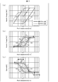
- FIG. 3A is a curve diagram showing the relationship of the friction torque (Nm) to the rack displacement (mm) between the ball joint portion 490 having a relatively high resistance force and the ball joint having a relatively low resistance force. is there.
- a ball joint having a relatively high resistance is referred to as a “high friction product”
- a ball joint having a relatively low resistance is referred to as a “low friction product”.
- the rack displacement (mm) is small, that is, the friction torque is not saturated in a region where the steering angle is small.
- the friction torque is saturated in a region where the rack displacement (mm) is small, that is, the steering angle is small.
- FIG. 3B shows the friction torque (Nm) with respect to the rack displacement (mm) of the ball joint portion 490 having a low resistance force from the friction torque (Nm) with respect to the rack displacement (mm) of the ball joint having a high resistance force. It is a curve figure which shows the difference of these. Arrows with reference signs I, II, and III are curve diagrams when initial cutting is performed in the right direction, and arrows with reference signs I ′, II ′, and III ′ are curve diagrams when initial cutting is performed in the left direction. It is.
- FIG. 3 (c) is a curve diagram in which the differential friction torque shown in FIG. 3 (b) is reversed ⁇ .
- the initial cut direction in the right direction is indicated by an arrow I
- the initial cut direction in the left direction is indicated by an arrow I '.
- the ECU 600 increases the absolute value of the current supplied to the turning force generating unit 220 as the absolute value of the rack displacement increases in the initial cuts indicated by the symbols I and I ′.
- ECU 600 applies a constant current to steering force generation unit 220.
- a current value in a direction opposite to the cutting direction is applied up to the first predetermined value and the second predetermined value, and the current value is an absolute value of the rack displacement. It can be said that the larger the value is, the larger the value becomes, and when the first predetermined value and the second predetermined value are exceeded, a current value in the direction opposite to the cutting direction is applied and the current value can be said to be constant.
- the ECU 600 decreases the absolute value of the current supplied to the turning force generating unit 220 as the absolute value of the rack displacement decreases.
- the ECU 600 increases the absolute value of the current supplied to the turning force generation unit 220 as the absolute value of the rack displacement decreases after the inflection point a (similarly, the inflection point b).
- the ECU 600 switches back to the right (initially to the left) when the rack displacement exceeds the second predetermined value.
- a constant current is applied to the turning force generator 220.
- the ECU 600 operates up to the inflection point b (inflection point a in the case of initial incision to the left).
- the absolute value of the rack displacement decreases, the absolute value of the current supplied to the turning force generator 220 is decreased.
- the ECU 600 increases the absolute value of the current supplied to the turning force generation unit 220 as the absolute value of the rack displacement decreases after the inflection point b (similarly, the inflection point a).
- the ECU 600 When the rack displacement exceeds the first predetermined value in the cut in the right direction (when the initial cut in the right direction is performed), the ECU 600 (the cut in the left direction (the initial cut in the left direction) In the case where the second predetermined value is exceeded), a constant current is applied to the turning force generator 220 even when the rack displacement is larger.
- the ECU 600 adjusts the steering control amount supplied to the torque application unit 460 so as to compensate for the difference shown in FIG.
- the ECU 600 adjusts the steering control amount by using the correction amount related to the resistance force of the ball joint portion 490, thereby preventing the steering feeling from being lost in a region where the steering angle is small, thereby preventing the steering feeling.
- the magnitude of the assist torque or reaction torque applied to the steering shaft 420 is controlled.
- the ECU 600 stores in advance the waveform shown in FIG. 3C as a correction map of the output current with respect to the rack displacement, and supplies the current corresponding to the rack displacement to the steering force generator 220 in consideration of the correction map.
- the steering feeling is improved by supplementing the friction torque of the ball joint portion 490 in a region where the steering angle is small.
- FIG. 4 is a diagram showing a schematic configuration of ECU 600.
- the ECU 600 includes a steering control unit 610.
- the steering control unit 610 refers to various sensor detection results included in the CAN 370 and determines the magnitude of the steering control amount supplied to the torque application unit 460.
- the expression “refer to” may include meanings such as “using”, “considering”, “depending on”, and the like.
- the process of “determining the magnitude of the control amount” includes the case where the control amount is set to zero, that is, the control amount is not supplied.
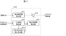
- FIG. 5 is a block diagram illustrating a configuration example of the steering control unit 610.
- the steering control unit 610 includes a basic control amount calculation unit 611, a rack displacement calculation unit (steering amount calculation unit) 612, a correction control amount calculation unit 613, a cut-in / return determination unit 614, and an addition unit 615. It has.
- the basic control amount calculation unit 611, the correction control amount calculation unit 613, and the addition unit 615 are collectively referred to as a steering control amount determination unit.
- the basic control amount calculation unit 611 refers to the steering torque supplied from the torque sensor 430, and calculates a basic control amount for controlling the magnitude of the assist torque or reaction torque.
- the basic control amount calculated by the basic control amount calculation unit 611 is added to the correction control amount calculated by the correction control amount calculation unit 613 and then supplied to the torque application unit 460 as a steering control amount.
- the rack displacement calculation unit 612 calculates the rack displacement by referring to the rotation angle of the assist motor and multiplying the rotation angle of the assist motor by a damping ratio corresponding to the gear ratio.
- the rack displacement calculation unit 612 calculates the rack displacement by taking the difference between the current value of the rack position and the previous value of the rack position.
- the vehicle 900 may include a rack displacement sensor that detects the rack displacement, and the rack displacement calculation unit 612 may calculate the rack displacement with reference to the detection result of the rack displacement sensor.
- the rack displacement calculation unit 612 may calculate the rack displacement with reference to the steering angle supplied from the steering angle sensor 440.
- the rack displacement calculation unit 612 calculates the steering amount input via the steering member 410 according to the rack displacement that is the displacement along the axial direction of the rack shaft 480.
- the cut / return determining unit 614 determines whether the rack displacement is generated in the cutting direction or the cut back direction. More specifically, the cut-in / back-out determination unit 614 determines whether the rack displacement is generated in the cutting direction or in the direction of switching back, based on the change between the previous absolute value and the current absolute value of the rack position. It is determined whether. If the change between the previous absolute value of the rack position and the current absolute value is a change in the plus direction, the cut-in / return determination unit 614 determines that the rack displacement is generated in the cutting direction. When the change between the previous absolute value of the rack position and the current absolute value is a change in the negative direction, the cut-in / return determination unit 614 determines that the rack displacement is generated in the direction of returning. The determination result by the cut-in / return determination unit 614 is supplied to the correction control amount calculation unit 613.
- the correction control amount calculation unit 613 calculates a current value corresponding to the rack displacement calculated by the rack displacement calculation unit 612 and the rack displacement direction determined by the cut-in / return determination unit 614.
- the correction control amount calculation unit 613 calculates a correction control amount corresponding to the rack displacement using the correction map indicating the friction torque difference illustrated in FIG.
- the addition unit 615 calculates the steering control amount by adding the correction control amount calculated by the correction control amount calculation unit 613 to the basic control amount calculated by the basic control amount calculation unit 611.
- the steering control amount calculated by the adding unit 615 is supplied to the torque applying unit 460.
- FIG. 6 is a diagram showing the relationship between rack displacement and friction torque.
- FIG. 6 shows a comparison between a case where a ball joint portion having a low resistance force is used and a case where the resistance force of the ball joint portion having a low resistance force is compensated by a control current.
- FIG. 6 shows a control current applied to compensate for the resistance of the ball joint having a low resistance.
- the steering control amount determination unit including the basic control amount calculation unit 611, the correction control amount calculation unit 613, and the addition unit 615 is set according to the friction torque characteristics of the ball joint unit 490.
- a correction control amount is calculated using the correction map, and the steering control amount is determined by adding the correction control amount and the basic control amount.
- the friction torque of the ball joint portion 490 can be supplemented in the fine steering angle region, and it is possible to prevent the steering feeling from being lost.
- the configuration in which the correction control amount is calculated based on the displacement along the axial direction of the rack shaft 480 has been described.
- the invention described in this specification is not limited to this.
- the rotation angle of the steering shaft 420 may be calculated, and the correction control amount determined by the calculated rotation angle and the correction map may be calculated.
- the steering control unit 610 refers to the configuration in which the correction control amount is calculated with reference to the rack displacement, but the invention described in the present specification is not limited to this.
- the steering control unit 610a of the second embodiment determines whether or not the steering member 410 is in the steering holding state, and processes the correction control amount according to whether or not the steering member 410 is in the steering holding state.
- a determination processing unit (steering determination unit) 617 is further provided.
- the steered state is a state where the steering member 410 is maintained at a constant rudder angle.
- members having the same functions as those described in the above embodiment are given the same reference numerals, and the description thereof will not be repeated.
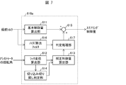
- FIG. 7 is a block diagram illustrating a configuration example of the steering control unit 610a according to the present embodiment.
- the steering control unit 610a differs from the steering control unit 610 described in the first embodiment in the following points.
- the steering control unit 610a includes a noise removal filter 616 and a determination processing unit 617.
- the basic control amount calculation unit 611, the correction control amount calculation unit 613, the determination processing unit 617, and the addition unit 615 are collectively referred to as a steering control amount determination unit.
- the noise removal filter 616 removes noise from the signal indicating the steering torque.
- the noise removal filter 616 may be configured to remove noise in a preset fixed frequency band, or may be configured to remove noise in a variable frequency band according to the vehicle speed.
- the determination processing unit 617 refers to the steering torque input to the determination processing unit 617 via the noise removal filter 616, and determines whether or not the steering member 410 is in the steered state. The determination processing unit 617 determines whether or not the steering member 410 is in the steered state by comparing the steering torque differential value with a threshold value.
- the determination processing unit 617 When the determination processing unit 617 determines that the steering member 410 is in the steered state, the determination processing unit 617 performs a process of reducing the correction control amount calculated by the correction control amount calculation unit 613. As an example, when the determination processing unit 617 determines that the steering member 410 is in the steered state, the determination control unit 617 replaces the correction control amount calculated by the correction control amount calculation unit 613 with zero. In other words, when it is determined that the steering member 410 is in the steered state, the correction control amount calculated by the correction control amount calculation unit 613 is not supplied to the addition unit 615. In this case, the addition unit 615 outputs the basic control amount calculated by the basic control amount calculation unit 611 as the steering control amount. Note that the determination processing unit 617 may calculate a correction control amount when the vehicle is in the steered state based on a correction control amount that is mapped in advance according to the steering torque, the steering angle, the vehicle speed, and the like.
- the determination processing unit 617 reduces the steering holding force by reducing the correction control amount, and maintains the stability of the steering member 410.
- the correction control amount calculation unit 613 receives the rack displacement calculated by the rack displacement calculation unit 612 and the determination result by the cut / return determination unit 614.
- the steering control speed may be further input into the correction control amount calculation part 613.
- the steered speed may be calculated by the ECU 600 from the amount of change of the rudder angle detected by the rudder angle sensor per predetermined time, or may be configured to be calculated by the correction control amount calculation unit 613.
- the correction control amount is appropriately processed based on whether or not the steering member 410 is in the steering holding state, the steering holding force and the stability of the steering member 410 are stable in the steering holding state.
- the steering control amount can be corrected so as to compensate for the characteristics. As a result, the steering feeling can be further improved.
- the steering control unit 610b calculates a steering amount input via the steering member 410 according to the steering angle, and calculates a correction control amount considering the torsion bar twist.
- members having the same functions as those described in the above embodiment are given the same reference numerals, and the description thereof is not repeated.
- FIG. 8 is a block diagram illustrating a configuration example of the steering control unit 610b according to the present embodiment.
- the steering control unit 610b is different from the steering control unit 610a described in the second embodiment in the following points.
- the steering control unit 610b includes a torsion bar twist correction unit 618.
- the steering torque (detected torque) detected by the torque sensor 430 is input to the torsion bar twist correction unit 618.
- the basic control amount calculation unit 611, the correction control amount calculation unit 613, the determination processing unit 617, the addition unit 615, and the torsion bar twist correction unit 618 are combined to determine the steering control amount. Part.
- the torsion bar twist correction unit 618 calculates the steering amount input via the steering member 410 according to the steering angle.
- the torsion bar torsion correction unit 618 calculates a steering angle by correcting the torsion bar torsion with reference to the rotation angle of the assist motor and the steering torque detected by the torque sensor 430.
- the torsion bar twist correction unit 618 multiplies the steering torque detected by the torque sensor 430 by the reciprocal of the spring rate of the torsion bar, and adds the steering angle calculated from the rotation angle of the assist motor to the value. Calculate the rudder angle corrected for the torsion.
- the torsion bar twist correction unit 618 calculates a correction control amount for compensating for the twist of the torsion bar with respect to the basic control amount, and outputs it as a second correction control amount.
- the rudder angle displacement calculation unit 612b refers to the rudder angle for which the torsion bar twist correction unit 618 has corrected the torsion bar twist amount, and the previous rudder angle value, the current rudder angle value, The steering angle displacement is calculated from the difference.
- the relationship between the steering angle displacement and the friction torque of this embodiment can be shown by replacing the rack stroke displacement in the compensation amount map shown in FIG. 6 with the steering angle.
- the determination processing unit 617 determines whether or not the steering member 410 is in the steered state, and the first correction control amount calculated by the correction control amount calculation unit 613 and the torsion bar twist amount. Based on the second correction control amount calculated by the correction unit 618, processing for adjusting the correction control amount is performed. In addition, when the determination processing unit 617 determines that the steering member 410 is in the steered state, the determination processing unit 617 performs processing to decrease the first correction control amount calculated by the correction control amount calculation unit 613. For example, as described in the second embodiment, the determination processing unit 617 determines the first correction control amount calculated by the correction control amount calculation unit 613 when it is determined that the steering member 410 is in the steered state. Replace with 0.
- the torsion bar torsion correction unit 618 is configured to calculate the rudder angle in which the torsion bar torsion is corrected using the detection result of the torque sensor 430, but the invention described in this specification. Is not limited to this.
- the torsion bar twist correction unit 618 refers to the detection result of the rudder angle sensor 440 and refers to the torsion bar.
- a rudder angle that corrects the torsional amount may be calculated.
- Control blocks (steering control unit 610, suspension control unit 650) of ECU 600 may be realized by a logic circuit (hardware) formed in an integrated circuit (IC chip) or the like, or using a CPU (Central Processing Unit). It may be realized by software.
- the ECU 600 includes a CPU that executes instructions of a program that is software that realizes each function, a ROM (Read Only Memory) or a storage device in which the program and various data are recorded so as to be readable by a computer (or CPU). (These are referred to as “recording media”), and a RAM (Random Access Memory) for developing the program. And the objective of this invention is achieved when a computer (or CPU) reads the said program from the said recording medium and runs it.
- a “non-temporary tangible medium” such as a tape, a disk, a card, a semiconductor memory, a programmable logic circuit, or the like can be used.
- the program may be supplied to the computer via an arbitrary transmission medium (such as a communication network or a broadcast wave) that can transmit the program.
- a transmission medium such as a communication network or a broadcast wave
- the present invention can also be realized in the form of a data signal embedded in a carrier wave in which the program is embodied by electronic transmission.
Landscapes
- Engineering & Computer Science (AREA)
- Chemical & Material Sciences (AREA)
- Combustion & Propulsion (AREA)
- Transportation (AREA)
- Mechanical Engineering (AREA)
- Steering Control In Accordance With Driving Conditions (AREA)
Abstract
サスペンションの減衰力の制御を路面状況に応じて適切に行う。操舵量を算出する操舵量算出部(612)と、操舵量算出部が算出した操舵量に基づいて補正量を算出し、算出した補正量に少なくとも基づいてステアリング制御量を決定するステアリング制御量決定部(611、613、615)とを備えている
Description
本発明は、ステアリング制御装置、及びステアリング装置に関する。
従来、電動モータの回転によりステアリング操作をアシストするステアリング装置が知られている。これらのステアリング装置では、車速や操舵角などのような車両状態に応じて適切な摩擦トルクがステアリングに付与されるように、モータの電流値を制御している。舵角と、摩擦トルクとの関係は、操舵感に影響するため、これらのステアリング装置では、操舵角が大きいときの摩擦トルクの値が、操舵角が小さいときの摩擦トルクの値よりも大きくなるように設定することで、舵角と、摩擦トルクとの関係のリニアリティを保っている。
上記のようなステアリング装置では、操舵感の向上を図ることが好ましい。
本発明は、操舵感の向上を図ることができる技術を提供することを目的とする。
かかる目的のもと、本発明は、ステアリングを制御するステアリング制御装置であって、操舵量を算出する操舵量算出部と、前記操舵量算出部が算出した操舵量に基づいて補正量を算出し、算出した補正量に少なくとも基づいてステアリング制御量を決定するステアリング制御量決定部とを備えている。
本発明によれば、操舵感の向上を図ることができる。
〔実施形態1〕
以下、本発明の実施形態1について、詳細に説明する。
以下、本発明の実施形態1について、詳細に説明する。
(車両900の構成)
図1は、本実施形態に係る車両900の概略構成を示す図である。図1に示すように、車両900は、懸架装置(サスペンション)100、車体200、車輪300、タイヤ310、操舵部材410、ステアリングシャフト420、トルクセンサ430、舵角センサ440、トルク印加部460、ラックピニオン機構470、ラック軸480、エンジン500、ECU(Electronic Control Unit)(制御装置、制御部)600、発電装置700およびバッテリ800を備えている。ここで、懸架装置100、及びECU600は、本実施形態に係るサスペンション装置を構成する。また、操舵部材410、ステアリングシャフト420、トルクセンサ430、舵角センサ440、トルク印加部460、ラックピニオン機構470、ラック軸480、及びECU600は、本実施形態に係るステアリング装置(操舵装置)を構成する。
図1は、本実施形態に係る車両900の概略構成を示す図である。図1に示すように、車両900は、懸架装置(サスペンション)100、車体200、車輪300、タイヤ310、操舵部材410、ステアリングシャフト420、トルクセンサ430、舵角センサ440、トルク印加部460、ラックピニオン機構470、ラック軸480、エンジン500、ECU(Electronic Control Unit)(制御装置、制御部)600、発電装置700およびバッテリ800を備えている。ここで、懸架装置100、及びECU600は、本実施形態に係るサスペンション装置を構成する。また、操舵部材410、ステアリングシャフト420、トルクセンサ430、舵角センサ440、トルク印加部460、ラックピニオン機構470、ラック軸480、及びECU600は、本実施形態に係るステアリング装置(操舵装置)を構成する。
タイヤ310が装着された車輪300は、懸架装置100によって車体200に懸架されている。車両900は、四輪車であるため、懸架装置100、車輪300およびタイヤ310については、それぞれ4つ設けられている。
なお、左側の前輪、右側の前輪、左側の後輪および右側の後輪のタイヤ及び車輪をそれぞれ、タイヤ310A及び車輪300A、タイヤ310B及び車輪300B、タイヤ310C及び車輪300C、並びに、タイヤ310D及び車輪300Dとも称する。以下、同様に、左側の前輪、右側の前輪、左側の後輪および右側の後輪にそれぞれ付随した構成を、符号「A」「B」「C」及び「D」を付して表現することがある。
懸架装置100は、油圧緩衝装置、アッパーアーム及びロアーアームを備えている。また、油圧緩衝装置は、一例として、当該油圧緩衝装置が発生させる減衰力を調整する電磁弁であるソレノイドバルブを備えている。ただし、これは本実施形態を限定するものではなく、油圧緩衝装置は、減衰力を調整する電磁弁として、ソレノイドバルブ以外の電磁弁を用いてもよい。例えば、上記電磁弁として、電磁流体(磁性流体)を利用した電磁弁を備える構成としてもよい。
エンジン500には、発電装置700が付設されており、発電装置700によって生成された電力がバッテリ800に蓄積される。
運転者の操作する操舵部材410は、ステアリングシャフト420の一端に対してトルク伝達可能に接続されており、ステアリングシャフト420の他端は、ラックピニオン機構470に接続されている。
ラックピニオン機構470は、ステアリングシャフト420の軸周りの回転を、ラック軸480の軸方向に沿った変位に変換するための機構である。ラック軸480が軸方向に変位すると、タイロッド482(482A,482B)及びナックルバー484(484A,484B)を介して車輪300(300A,300B)が転舵される。
トルクセンサ430は、ステアリングシャフト420に印加される操舵トルク、換言すれば、操舵部材410に印加される操舵トルクを検出し、検出結果を示すトルクセンサ信号をECU600に提供する。より具体的には、トルクセンサ430は、ステアリングシャフト420に内設されたトーションバーの捩れを検出し、検出結果をトルクセンサ信号として出力する。なお、トルクセンサ430として、ホールIC,MR素子、磁歪式トルクセンサなどの周知のセンサを用いてもよい。
舵角センサ440は、操舵部材410の舵角を検出し、検出結果をECU600に提供する。
トルク印加部460は、ECU600から供給されるステアリング制御量に応じたアシストトルク又は反力トルクを、ステアリングシャフト420に印加する。トルク印加部460は、ステアリング制御量に応じたアシストトルク又は反力トルクを発生させるアシストモータと、当該アシストモータが発生させたトルクをステアリングシャフト420に伝達するトルク伝達機構とを備えている。また、トルク印加部460は、アシストモータの回転速を検出するモータ回転速センサと、アシストモータの回転角を検出するモータ回転角センサと、を備えている。
なお、本明細書における「制御量」の具体例として、電流値、デューティー比、減衰率、減衰比等が挙げられる。
なお、上述の説明において「トルク伝達可能に接続」とは、一方の部材の回転に伴い他方の部材の回転が生じるように接続されていることを指し、例えば、一方の部材と他方の部材とが一体的に成形されている場合、一方の部材に対して他方の部材が直接的又は間接的に固定されている場合、及び、一方の部材と他方の部材とが継手部材等を介して連動するよう接続されている場合を少なくとも含む。
また、上記の例では、操舵部材410からラック軸480までが常時機械的に接続されたステアリング装置を例に挙げたが、これは本実施形態を限定するものではなく、本実施形態に係るステアリング装置は、例えばステア・バイ・ワイヤ方式のステアリング装置であってもよい。ステア・バイ・ワイヤ方式のステアリング装置に対しても本明細書において以下に説明する事項を適用することができる。
また、図1では、トルク印加部をステアリングシャフト上に設ける所謂コラムアシスト式のステアリング装置を図示しているが、これは本実施形態を限定するものではない。トルク印加部をラック軸上に設ける所謂ラックアシスト式のステアリング装置としてもよい。
ECU600は、車両900が備える各種の電子機器を統括制御する。より具体的には、ECU600は、トルク印加部460に供給するステアリング制御量を調整することにより、ステアリングシャフト420に印加するアシストトルク又は反力トルクの大きさを制御する。
また、ECU600は、懸架装置100に含まれる油圧緩衝装置が備えるソレノイドバルブに対して、サスペンション制御量を供給することによって当該ソレノイドバルブの開閉を制御する。この制御を可能とするために、ECU600からソレノイドバルブへ駆動電力を供給する電力線が配されている。
また、車両900は、車輪300毎に設けられ各車輪300の車輪速を検出する車輪速センサ320、車両900の横方向の加速度を検出する横Gセンサ330、車両900の前後方向の加速度を検出する前後Gセンサ340、車両900のヨーレートを検出するヨーレートセンサ350、エンジン500が発生させるトルクを検出するエンジントルクセンサ510、エンジン500の回転数を検出するエンジン回転数センサ520、及びブレーキ装置が有するブレーキ液に印加される圧力を検出するブレーキ圧センサ530を備えている。これらの各種センサによる検出結果は、ECU600に供給される。
なお、図示は省略するが、車両900は、ブレーキ時の車輪ロックを防ぐためのシステムであるABS(Antilock Brake System)、加速時等における車輪の空転を抑制するTCS(Traction Control System)、及び、旋回時のヨーモーメント制御やブレーキアシスト機能等のための自動ブレーキ機能を備えた車両挙動安定化制御システムであるVSA(Vehicle Stability Assist)制御可能なブレーキ装置を備えている。
ここで、ABS、TCS、及びVSAは、推定した車体速に応じて定まる車輪速と、車輪速センサ320によって検出された車輪速とを比較し、これら2つの車輪速の値が、所定の値以上相違している場合にスリップ状態であると判定する。ABS、TCS、及びVSAは、このような処理を通じて、車両900の走行状態に応じて最適なブレーキ制御やトラクション制御を行うことにより、車両900の挙動の安定化を図るものである。
また、上述した各種のセンサによる検出結果のECU600への供給、及び、ECU600から各部への制御信号の伝達は、CAN(Controller Area Network)370を介して行われる。
CAN370を介してECU600へ供給される信号は、例えば、以下の信号を含んでいる(括弧書きは取得元を示す)。
・4輪の車輪速(車輪速センサ320A~D)
・ヨーレート(ヨーレートセンサ350)
・前後G(前後Gセンサ340)
・横G(横Gセンサ330)
・ブレーキ圧(ブレーキ圧センサ530)
・エンジントルク(エンジントルクセンサ510)
・エンジン回転数(エンジン回転数センサ520)
・舵角(舵角センサ440)
・操舵トルク(トルクセンサ430)
図2は、タイロッド482とナックルバー484とを連結する連結部材の一例としてのボールジョイント部490を示す図である。図2に示すようにボールジョイント部490は、ボール受け部492と、ボール部494と、を備えて構成されている。ボール部494は、金属から形成された金属球と、当該金属球と一体に形成された棒状部とを有している。ボール受け部492は、ボール部494の金属球に球面接触する部材である。ボールジョイント部490は、タイロッド482とナックルバー484とを、任意の方向に互いに回転可能に結合する。
・ヨーレート(ヨーレートセンサ350)
・前後G(前後Gセンサ340)
・横G(横Gセンサ330)
・ブレーキ圧(ブレーキ圧センサ530)
・エンジントルク(エンジントルクセンサ510)
・エンジン回転数(エンジン回転数センサ520)
・舵角(舵角センサ440)
・操舵トルク(トルクセンサ430)
図2は、タイロッド482とナックルバー484とを連結する連結部材の一例としてのボールジョイント部490を示す図である。図2に示すようにボールジョイント部490は、ボール受け部492と、ボール部494と、を備えて構成されている。ボール部494は、金属から形成された金属球と、当該金属球と一体に形成された棒状部とを有している。ボール受け部492は、ボール部494の金属球に球面接触する部材である。ボールジョイント部490は、タイロッド482とナックルバー484とを、任意の方向に互いに回転可能に結合する。
なお、図2では、タイロッド482にボール受け部492が接続され、ナックルバー484にボール部494が接続されている形態を例に示しているが、ボールジョイント部490の接続構成は、これに限られるものではない。ボールジョイント部490は、タイロッド482とナックルバー484との、何れか一方にボール受け部492が、何れか他方にボール部494が接続されていればよく、どちらの構成であっても、同様の機能を実現することができる。
ボールジョイント部490は、ボール受け部492と、ボール部494と、の球面接触する面間の摩擦抵抗(抵抗力)によって生じる摩擦トルクが、メーカーや、製品によって異なっている。図3(a)は、抵抗力が相対的に高いボールジョイント部490と、抵抗力が相対的に低いボールジョイントとの、ラック変位(mm)に対する摩擦トルク(Nm)の関係を示す曲線図である。図3(a)では、抵抗力が相対的に高いボールジョイントを「高フリクション品」と記し、抵抗力が相対的に低いボールジョイントを「低フリクション品」と記す。
図3(a)に示すように、抵抗力が高いボールジョイントでは、ラック変位(mm)が小さい、つまり、舵角が小さい領域で摩擦トルクの飽和が生じることがない。これに対して、抵抗力が低いボールジョイントでは、ラック変位(mm)が小さい、つまり、舵角が小さい領域で摩擦トルクの飽和が生じている。
抵抗力の高いボールジョイントをボールジョイント部として採用した場合、一般的に摩擦による摩耗のため劣化が早く、また、製造コスト高くなる傾向がある。これに比べて、抵抗力が低いボールジョイントをボールジョイント部490として採用した場合、耐摩耗性能が高く、製造コストも低く抑えることができる。
その一方で、抵抗力が低いボールジョイントをボールジョイント部490として採用した場合、操舵角が小さい領域で、ボールジョイント部490の摩擦トルクが飽和することにより、ステアリングの操舵感に抜け感が生じる場合があった。
図3(b)は、抵抗力が高いボールジョイントの、ラック変位(mm)に対する摩擦トルク(Nm)からの、抵抗力が低いボールジョイント部490の、ラック変位(mm)に対する摩擦トルク(Nm)の差分を示す曲線図である。符号I,II,IIIを付した矢印は右方向へ初期切り込みをした場合の曲線図であり、符号I’,II’,III’を付した矢印は左方向へ初期切り込みをした場合の曲線図である。
図3(c)は、図3(b)に示した差分の摩擦トルクを±逆にした曲線図である。
図3(b)、図3(c)では、右方向への初期切り込み方向を符号I、左方向への初期切り込み方向を符号I’を付した矢印で示している。
符号I,I’で示した初期切り込みにおいて、ラック変位の絶対値が大きくなるほど、ECU600は、転舵力発生部220に供給する電流の絶対値を大きくする。
なお、右方向への初期切り込みにおいて、ラック変位が第1所定値を超えた場合には(左方向への初期切り込みにおいては、ラック変位が第2所定値を超えた場合には)ラック変位の絶対値が更に大きい場合でも、ECU600は、転舵力発生部220に一定の電流を付与する。
つまり、符号I,I’で示した切り込み時において、第1所定値、第2所定値までは、切り込み方向とは逆の方向の電流値を付与し、その電流値はラック変位の絶対値が大きくなるほど大きくすると言うことができ、第1所定値、第2所定値を超えたときには、切り込み方向とは逆の方向の電流値を付与し、電流値は一定にすると言う事ができる。
これにより、低フリクション品と高フリクション品の差分となる抵抗力を補償することができる。
また、図3(b)、図3(c)では、左方向への切り戻し方向(右方向への初期切り込みをした場合)をII、右方向への切り戻し方向(左方向への初期切り込みをした場合)をII’を付した矢印で示している。
図3(b)、図3(c)に示すように、符号II,II’で示した切り戻しにおいて、変曲点a(図中左に初期切り込みした場合は、変曲点b)までは、ECU600は、ラック変位の絶対値の減少に伴い、転舵力発生部220に供給する電流の絶対値を小さくする。ECU600は、変曲点a(同様に変曲点b)以降は、ラック変位の絶対値の減少に伴い、転舵力発生部220に供給する電流の絶対値を大きくする。なお、左方向への切り戻し(右方向への処置切り込みをした場合)において、ECU600は、ラック変位が第2所定値を超えた場合には(右方向への切り戻し(左方向への初期切り込みをした場合)においては、第1所定値を超えた場合には)、ラック変位の絶対値が更に大きい場合でも、転舵力発生部220に一定の電流を付与する。
また、図3(b)、図3(c)では、右方向への切り込み方向(右方向への初期切り込みをした場合)をIII、左方向への切り込み方向(左方向への初期切り込みをした場合)をIII’を付した矢印で示している。
図3(b)、図3(c)に示すように、符号III,III’で示した切り込みにおいて、変曲点b(左に初期切り込みした場合は、変曲点a)までは、ECU600は、ラック変位の絶対値の減少に伴い、転舵力発生部220に供給する電流の絶対値を小さくする。ECU600は、変曲点b(同様に変曲点a)以降は、ラック変位の絶対値の減少に伴い、転舵力発生部220に供給する電流の絶対値を大きくする。
なお、右方向への切り込み(右方向への初期切り込みをした場合)において、ECU600は、ラック変位が第1所定値を超えた場合には、(左方向への切り込み(左方向への初期切り込みをした場合)においては、第2所定値を超えた場合には)、ラック変位が更に大きい場合でも、転舵力発生部220に一定の電流を付与する。
このように、ECU600は、図3(b)に示した差分を補うように、トルク印加部460に供給するステアリング制御量を調整する。このように、ECU600は、ボールジョイント部490の抵抗力に関する補正量を用いてステアリング制御量を調整することで、操舵角が小さい領域でステアリングの操舵感に抜け感が生じるのを防ぎ、操舵感の向上を図るべく、ステアリングシャフト420に印加するアシストトルク又は反力トルクの大きさを制御する。ECU600は、図3(c)に示した波形を、ラック変位に対する出力電流の補正マップとして予め記憶し、当該補正マップを考慮して、ラック変位に対応する電流を転舵力発生部220に供給することで、操舵角が小さい領域で、ボールジョイント部490の摩擦トルクを補うことにより、操舵感の向上を図る。
(ECU600)
以下では、参照する図面を替えて、ECU600について具体的に説明する。図4は、ECU600の概略構成を示す図である。
以下では、参照する図面を替えて、ECU600について具体的に説明する。図4は、ECU600の概略構成を示す図である。
図4に示すように、ECU600は、ステアリング制御部610を備えている。
ステアリング制御部610は、CAN370に含まれる各種のセンサ検出結果を参照し、トルク印加部460に供給するステアリング制御量の大きさを決定する。
なお、本明細書において「~を参照して」との表現には、「~を用いて」「~を考慮して」「~に依存して」などの意味が含まれ得る。
また、「制御量の大きさを決定する」との処理には、制御量の大きさをゼロに設定する、すなわち、制御量を供給しない場合も含まれる。
(ステアリング制御部)
続いて、図5を参照して、ステアリング制御部610についてより具体的に説明する。図5は、ステアリング制御部610の構成例を示すブロック図である。
続いて、図5を参照して、ステアリング制御部610についてより具体的に説明する。図5は、ステアリング制御部610の構成例を示すブロック図である。
図5に示すように、ステアリング制御部610は、基本制御量算出部611、ラック変位算出部(操舵量算出部)612、補正制御量算出部613、切り込み切り戻し判定部614、及び加算部615を備えている。なお、本実施形態では、基本制御量算出部611と、補正制御量算出部613と、加算部615とを合わせてステアリング制御量決定部と称する。
基本制御量算出部611は、トルクセンサ430から供給される操舵トルクを参照し、アシストトルク又は反力トルクの大きさを制御するための基本制御量を算出する。基本制御量算出部611によって算出された基本制御量は、補正制御量算出部613によって算出された補正制御量と合算されたうえで、ステアリング制御量としてトルク印加部460に供給される。
ラック変位算出部612は、アシストモータの回転角を参照し、アシストモータの回転角に対して、ギア比に応じた減衰比を掛けることでラック変位を算出する。ラック変位算出部612は、ラック位置の今回の値と、ラック位置の前回の値との差分を取ることで、ラック変位を算出する。なお、車両900が、ラック変位を検出するラック変位センサを備え、ラック変位算出部612は、当該ラック変位センサの検出結果を参照してラック変位を算出してもよい。
また、ラック変位算出部612は、舵角センサ440から供給される舵角を参照して、ラック変位を算出してもよい。
このようにラック変位算出部612は、操舵部材410を介して入力される操舵量を、ラック軸480の軸方向に沿った変位であるラック変位に応じて算出するものである。
切り込み切り戻し判定部614は、ラック変位が切り込んでいる方向に生じているのか、切り戻す方向に生じているのかを判定する。詳述すると、切り込み切り戻し判定部614は、ラック位置の前回の絶対値と、今回の絶対値との変化から、ラック変位が切り込んでいる方向に生じているのか、切り戻す方向に生じているのかを判定する。切り込み切り戻し判定部614は、ラック位置の前回の絶対値と、今回の絶対値との変化がプラス方向への変化であれば、ラック変位が切り込んでいる方向に生じていると判定する。切り込み切り戻し判定部614は、ラック位置の前回の絶対値と、今回の絶対値との変化がマイナス方向への変化であれば、ラック変位が切り戻す方向に生じていると判定する。切り込み切り戻し判定部614による判定結果は、補正制御量算出部613に供給される。
補正制御量算出部613は、ラック変位算出部612によって算出されたラック変位と、切り込み切り戻し判定部614によって判定されたラック変位の方向と、に対応した電流値を算出する。補正制御量算出部613は、図3(c)に例示した摩擦トルク差分を示す補正マップを用いて、ラック変位に対応した補正制御量を算出する。
加算部615は、基本制御量算出部611によって算出された基本制御量に、補正制御量算出部613によって算出された補正制御量を加算することで、ステアリング制御量を算出する。加算部615で算出されたステアリング制御量は、トルク印加部460に供給される。
図6は、ラック変位と摩擦トルクとの関係を示す図である。図6では、抵抗力の低いボールジョイント部を用いた場合と、抵抗力の低いボールジョイント部の抵抗力を制御電流で補った場合と、を比較して示している。また、図6には、抵抗力の低いボールジョイント部の抵抗力を補うために印加した制御電流を示している。
図6に示すように、ボールジョイント部の特性に応じた補正制御量を用いてトルク印加部460に供給する電流を補正することで、抵抗力の低いボールジョイント部を用いても、抵抗力の高いボールジョイント部を用いた場合と同様の摩擦トルクを得ることができる。よって、ボールジョイント部490の抵抗力に因らず、操舵感の向上を図ることができる。
このように、基本制御量算出部611と、補正制御量算出部613と、加算部615とを備えているステアリング制御量決定部は、ボールジョイント部490の摩擦トルクの特性に応じて設定される補正マップを用いて補正制御量を算出し、当該補正制御量と、基本制御量とを合算して、ステアリング制御量を決定する。これにより、微舵角領域で、ボールジョイント部490の摩擦トルクを補うことができ、操舵感に抜け感が生じるのを防ぐことができる。
なお、本実施形態では、ラック軸480の軸方向に沿った変位に基づいて補正制御量を算出する構成について説明したが、本明細書に記載の発明はこれに限定されるものではない。ラック軸480の軸方向に沿った変位に代えて、ステアリングシャフト420の回転角を算出し、算出した回転角と補正マップとによって定まる補正制御量を算出する構成であってもよい。
〔実施形態2〕
実施形態1では、ステアリング制御部610は、ラック変位を参照して補正制御量を算出する構成を例に挙げたが、本明細書に記載の発明はこれに限定されるものではない。実施形態2のステアリング制御部610aは、実施形態1の構成に加えて、操舵部材410が保舵状態にあるか否を判定し、保舵状態にあるか否かに応じて補正制御量を処理する判定処理部(保舵判定部)617を更に備えている。なお、保舵状態とは、操舵部材410が一定の舵角で維持されている状態のことである。また、説明の便宜上、上記実施形態にて説明した部材と同じ機能を有する部材については、同じ符号を付記し、その説明を繰り返さない。
実施形態1では、ステアリング制御部610は、ラック変位を参照して補正制御量を算出する構成を例に挙げたが、本明細書に記載の発明はこれに限定されるものではない。実施形態2のステアリング制御部610aは、実施形態1の構成に加えて、操舵部材410が保舵状態にあるか否を判定し、保舵状態にあるか否かに応じて補正制御量を処理する判定処理部(保舵判定部)617を更に備えている。なお、保舵状態とは、操舵部材410が一定の舵角で維持されている状態のことである。また、説明の便宜上、上記実施形態にて説明した部材と同じ機能を有する部材については、同じ符号を付記し、その説明を繰り返さない。
図7は、本実施形態に係るステアリング制御部610aの構成例を示すブロック図である。
図7に示すように、ステアリング制御部610aは、実施形態1において説明したステアリング制御部610と以下の点において異なる。
すなわち、ステアリング制御部610aは、ノイズ除去フィルタ616と、判定処理部617と、を備えている。本実施形態では、基本制御量算出部611と、補正制御量算出部613と、判定処理部617と、加算部615と、を合わせてステアリング制御量決定部と称する。
ノイズ除去フィルタ616は、操舵トルクを示す信号からノイズを除去する。ノイズ除去フィルタ616は、予め設定された固定周波数帯のノイズを除去する構成であってもよいし、車速に応じて可変の周波数帯のノイズを除去する構成であってもよい。
判定処理部617は、ノイズ除去フィルタ616を介して判定処理部617に入力される操舵トルクを参照して、操舵部材410が保舵状態にあるか否を判定する。判定処理部617は、操舵トルク微分値と、閾値とを比較することで、操舵部材410が保舵状態にあるか否を判定する。
判定処理部617は、操舵部材410が保舵状態にあると判定した場合には、補正制御量算出部613によって算出された補正制御量を減少させる処理を行う。一例として、判定処理部617は、操舵部材410が保舵状態にあると判定した場合には、補正制御量算出部613によって算出された補正制御量を0に置き換える。換言すれば、操舵部材410が保舵状態にあると判定した場合、補正制御量算出部613によって算出された補正制御量を、加算部615に供給しない。この場合、加算部615は、基本制御量算出部611によって算出された基本制御量をステアリング制御量として出力する。なお、判定処理部617は、予め操舵トルク、舵角、車速等に応じてマッピングされた補正制御量に基づいて、保舵状態にある場合の補正制御量を算出してもよい。
操舵部材410が保舵状態にある場合には、判定処理部617は補正制御量を減少させることで保舵力を低減させ、操舵部材410の安定性を保つ。
補正制御量算出部613には、ラック変位算出部612によって算出されたラック変位、及び切り込み切り戻し判定部614による判定結果が入力される。なお、図示は省略するが、補正制御量算出部613には、更に転舵速が入力されても良い。転舵速は、舵角センサによって検出された舵角の所定時間当たりの変化量からECU600によって算出されてもよいし、補正制御量算出部613によって算出される構成であってもよい。
これらの構成によれば、操舵部材410が保舵状態であるか否かに基づいて、補正制御量が適宜処理されるため、保舵状態である場合に、保舵力と操舵部材410の安定性とを補うようにステアリング制御量を補正することができる。これにより、更に操舵感の向上を図ることができる。
〔実施形態3〕
実施形態3のステアリング制御部610bは、操舵部材410を介して入力される操舵量を、舵角に応じて算出すると共に、トーションバーの捩れ分を考慮した補正制御量を算出する。説明の便宜上、上記実施形態にて説明した部材と同じ機能を有する部材については、同じ符号を付記し、その説明を繰り返さない。
実施形態3のステアリング制御部610bは、操舵部材410を介して入力される操舵量を、舵角に応じて算出すると共に、トーションバーの捩れ分を考慮した補正制御量を算出する。説明の便宜上、上記実施形態にて説明した部材と同じ機能を有する部材については、同じ符号を付記し、その説明を繰り返さない。
図8は、本実施形態に係るステアリング制御部610bの構成例を示すブロック図である。
図8に示すように、ステアリング制御部610bは、実施形態2において説明したステアリング制御部610aと以下の点において異なる。
すなわち、ステアリング制御部610bは、トーションバー捩れ分補正部618を備えている。また、トーションバー捩れ分補正部618には、トルクセンサ430が検出した操舵トルク(検出トルク)が入力される。なお、本実施形態では、基本制御量算出部611と、補正制御量算出部613と、判定処理部617と、加算部615と、トーションバー捩れ分補正部618と、を合わせてステアリング制御量決定部と称する。
トーションバー捩れ分補正部618は、操舵部材410を介して入力される操舵量を舵角に応じて算出する。一例として、トーションバー捩れ分補正部618は、アシストモータの回転角と、トルクセンサ430が検出した操舵トルクと、を参照して、トーションバーの捩れ分を補正した舵角を算出する。トーションバー捩れ分補正部618は、トルクセンサ430が検出した操舵トルクに、トーションバーのバネレートの逆数を乗算し、その値にアシストモータの回転角から算出した操舵角を加算することで、トーションバーの捩れ分を補正した舵角を算出する。また、トーションバー捩れ分補正部618は、基本制御量に対して、トーションバーの捩れ分を補うための補正制御量を算出し、第2の補正制御量として出力する。
本実施形態に係る舵角変位算出部612bは、トーションバー捩れ分補正部618によってトーションバーの捩れ分が補正された舵角を参照して、前回の舵角値と、今回の舵角値との差分から舵角変位を算出する。なお、図6に示した補償量マップのラックストロークの変位を、舵角に置き換えることで、本実施形態の舵角変位と摩擦トルクとの関係を示すことができる。
本実施形態に係る判定処理部617は、操舵部材410が保舵状態にあるか否かを判定するとともに、補正制御量算出部613によって算出された第1の補正制御量と、トーションバー捩れ分補正部618によって算出された第2の補正制御量と、に基づいて、補正制御量を調整する処理を行う。また、判定処理部617は、操舵部材410が保舵状態にあると判定した場合には、補正制御量算出部613によって算出された第1の補正制御量を減少させる処理を行う。例えば、実施形態2において説明したように、判定処理部617は、操舵部材410が保舵状態にあると判定した場合には、補正制御量算出部613によって算出された第1の補正制御量を0に置き換える。
なお、本実施形態では、トーションバー捩れ分補正部618は、トルクセンサ430の検出結果を用いてトーションバーの捩れ分を補正した舵角を算出する構成としたが、本明細書に記載の発明はこれに限定されるものではない。舵角センサ440が操舵部材410に対してトーションバーよりもラック軸480側にある構成の場合には、トーションバー捩れ分補正部618は、舵角センサ440の検出結果を参照して、トーションバーの捩れ分を補正した舵角を算出してもよい。
〔ソフトウェアによる実現例〕
ECU600の制御ブロック(ステアリング制御部610、サスペンション制御部650)は、集積回路(ICチップ)等に形成された論理回路(ハードウェア)によって実現してもよいし、CPU(Central Processing Unit)を用いてソフトウェアによって実現してもよい。
ECU600の制御ブロック(ステアリング制御部610、サスペンション制御部650)は、集積回路(ICチップ)等に形成された論理回路(ハードウェア)によって実現してもよいし、CPU(Central Processing Unit)を用いてソフトウェアによって実現してもよい。
後者の場合、ECU600は、各機能を実現するソフトウェアであるプログラムの命令を実行するCPU、上記プログラムおよび各種データがコンピュータ(またはCPU)で読み取り可能に記録されたROM(Read Only Memory)または記憶装置(これらを「記録媒体」と称する)、上記プログラムを展開するRAM(Random Access Memory)などを備えている。そして、コンピュータ(またはCPU)が上記プログラムを上記記録媒体から読み取って実行することにより、本発明の目的が達成される。上記記録媒体としては、「一時的でない有形の媒体」、例えば、テープ、ディスク、カード、半導体メモリ、プログラマブルな論理回路などを用いることができる。また、上記プログラムは、該プログラムを伝送可能な任意の伝送媒体(通信ネットワークや放送波等)を介して上記コンピュータに供給されてもよい。なお、本発明は、上記プログラムが電子的な伝送によって具現化された、搬送波に埋め込まれたデータ信号の形態でも実現され得る。
本発明は上述した各実施形態に限定されるものではなく、請求項に示した範囲で種々の変更が可能であり、異なる実施形態にそれぞれ開示された技術的手段を適宜組み合わせて得られる実施形態についても本発明の技術的範囲に含まれる。
410 操舵部材
420 ステアリングシャフト
430 トルクセンサ
440 舵角センサ
460 トルク印加部
470 ラックピニオン機構
480 ラック軸
482 タイロッド
484 ナックルバー(ナックルアーム)
490 ボールジョイント部
494 ボール部
600 ECU
610、610a、610b ステアリング制御部(ステアリング制御装置)
611 基本制御量算出部
612 ラック変位算出部(操舵量算出部)
613 補正制御量算出部
614 切り込み切り戻し判定部
615 加算部
616 ノイズ除去フィルタ
617 判定処理部(保舵判定部)
618 トーションバー捩れ分補正部
900 車両
420 ステアリングシャフト
430 トルクセンサ
440 舵角センサ
460 トルク印加部
470 ラックピニオン機構
480 ラック軸
482 タイロッド
484 ナックルバー(ナックルアーム)
490 ボールジョイント部
494 ボール部
600 ECU
610、610a、610b ステアリング制御部(ステアリング制御装置)
611 基本制御量算出部
612 ラック変位算出部(操舵量算出部)
613 補正制御量算出部
614 切り込み切り戻し判定部
615 加算部
616 ノイズ除去フィルタ
617 判定処理部(保舵判定部)
618 トーションバー捩れ分補正部
900 車両
Claims (7)
- ステアリングを制御するステアリング制御装置であって、
操舵量を算出する操舵量算出部と、
前記操舵量算出部が算出した操舵量に基づいて補正量を算出し、算出した補正量に少なくとも基づいてステアリング制御量を決定するステアリング制御量決定部と
を備えていることを特徴とするステアリング制御装置。 - 前記補正量は、操舵装置の備える連結部材の抵抗力に関する補正量であることを特徴とする請求項1に記載のステアリング制御装置。
- 前記補正量は、タイロッドとナックルアームとを連結するボールジョイントの抵抗力に関する補正量であることを特徴とする請求項2に記載のステアリング制御装置。
- 前記操舵量算出部は、前記操舵量をラック変位に応じて算出することを特徴とする請求項1から3の何れか1項に記載のステアリング制御装置。
- 前記操舵量算出部は、前記操舵量を舵角に応じて算出することを特徴とする請求項1から3の何れか1項に記載のステアリング制御装置。
- 保舵状態にあるか否かを判定する判定を行う保舵判定部を更に備え、
前記保舵判定部が、保舵状態にあると判定した場合、上記ステアリング制御量決定部は、前記補正量を減少させる
ことを特徴とする請求項1から5の何れか1項に記載のステアリング制御装置。 - 請求項1から6の何れか1項に記載のステアリング制御装置を備えていることを特徴とするステアリング装置。
Applications Claiming Priority (2)
| Application Number | Priority Date | Filing Date | Title |
|---|---|---|---|
| JP2018-016553 | 2018-02-01 | ||
| JP2018016553 | 2018-02-01 |
Publications (1)
| Publication Number | Publication Date |
|---|---|
| WO2019150587A1 true WO2019150587A1 (ja) | 2019-08-08 |
Family
ID=67478400
Family Applications (1)
| Application Number | Title | Priority Date | Filing Date |
|---|---|---|---|
| PCT/JP2018/005177 Ceased WO2019150587A1 (ja) | 2018-02-01 | 2018-02-15 | ステアリング制御装置、及びステアリング装置 |
Country Status (1)
| Country | Link |
|---|---|
| WO (1) | WO2019150587A1 (ja) |
Cited By (2)
| Publication number | Priority date | Publication date | Assignee | Title |
|---|---|---|---|---|
| CN115551766A (zh) * | 2020-06-02 | 2022-12-30 | 日立安斯泰莫株式会社 | 电动助力转向控制装置及电动助力转向装置 |
| JP2023071032A (ja) * | 2021-11-10 | 2023-05-22 | 日本精工株式会社 | 車両用操向システムの制御装置 |
Citations (3)
| Publication number | Priority date | Publication date | Assignee | Title |
|---|---|---|---|---|
| JPH10316005A (ja) * | 1997-05-20 | 1998-12-02 | Kayaba Ind Co Ltd | 電動パワーステアリング制御装置 |
| JP2005212643A (ja) * | 2004-01-30 | 2005-08-11 | Toyota Motor Corp | パワーステアリング装置 |
| JP2011105190A (ja) * | 2009-11-19 | 2011-06-02 | Honda Motor Co Ltd | 電動パワーステアリング装置 |
-
2018
- 2018-02-15 WO PCT/JP2018/005177 patent/WO2019150587A1/ja not_active Ceased
Patent Citations (3)
| Publication number | Priority date | Publication date | Assignee | Title |
|---|---|---|---|---|
| JPH10316005A (ja) * | 1997-05-20 | 1998-12-02 | Kayaba Ind Co Ltd | 電動パワーステアリング制御装置 |
| JP2005212643A (ja) * | 2004-01-30 | 2005-08-11 | Toyota Motor Corp | パワーステアリング装置 |
| JP2011105190A (ja) * | 2009-11-19 | 2011-06-02 | Honda Motor Co Ltd | 電動パワーステアリング装置 |
Cited By (3)
| Publication number | Priority date | Publication date | Assignee | Title |
|---|---|---|---|---|
| CN115551766A (zh) * | 2020-06-02 | 2022-12-30 | 日立安斯泰莫株式会社 | 电动助力转向控制装置及电动助力转向装置 |
| JP2023071032A (ja) * | 2021-11-10 | 2023-05-22 | 日本精工株式会社 | 車両用操向システムの制御装置 |
| JP7745436B2 (ja) | 2021-11-10 | 2025-09-29 | Nskステアリング&コントロール株式会社 | 車両用操向システムの制御装置 |
Similar Documents
| Publication | Publication Date | Title |
|---|---|---|
| US11254353B2 (en) | Control device and steering device | |
| US11110912B2 (en) | Vehicle control device, and vehicle | |
| US11472470B2 (en) | Control device for applying torque to a steering member | |
| US11247685B2 (en) | Road surface determination device, suspension control device, and suspension device | |
| US11376916B2 (en) | Suspension control device and suspension device | |
| JP6359163B1 (ja) | サスペンション制御装置、および、サスペンション装置 | |
| WO2020003550A1 (ja) | ステアリング制御装置及びステアリング装置 | |
| US11548344B2 (en) | Suspension control device and suspension device | |
| JP2018090248A (ja) | 車両制御装置、および、車両 | |
| WO2020003549A1 (ja) | ステアリング制御装置及びステアリング装置 | |
| WO2019150587A1 (ja) | ステアリング制御装置、及びステアリング装置 | |
| WO2018173303A1 (ja) | 制御装置、および、サスペンション装置 | |
| JP7526643B2 (ja) | 操舵力制御装置、ステアリング制御装置及びステアバイワイヤシステム | |
| JP7186072B2 (ja) | 保舵判定装置、ステアリング制御装置、及びステアリング装置 | |
| JP4572915B2 (ja) | 車輌用操舵制御装置 | |
| JP6775069B2 (ja) | ラック軸力推定装置 |
Legal Events
| Date | Code | Title | Description |
|---|---|---|---|
| 121 | Ep: the epo has been informed by wipo that ep was designated in this application |
Ref document number: 18904327 Country of ref document: EP Kind code of ref document: A1 |
|
| NENP | Non-entry into the national phase |
Ref country code: DE |
|
| 122 | Ep: pct application non-entry in european phase |
Ref document number: 18904327 Country of ref document: EP Kind code of ref document: A1 |