WO2019146381A1 - Work vehicle - Google Patents
Work vehicle Download PDFInfo
- Publication number
- WO2019146381A1 WO2019146381A1 PCT/JP2018/048624 JP2018048624W WO2019146381A1 WO 2019146381 A1 WO2019146381 A1 WO 2019146381A1 JP 2018048624 W JP2018048624 W JP 2018048624W WO 2019146381 A1 WO2019146381 A1 WO 2019146381A1
- Authority
- WO
- WIPO (PCT)
- Prior art keywords
- steering
- vehicle body
- switch
- correction
- vehicle
- Prior art date
Links
- 238000012937 correction Methods 0.000 claims description 343
- 238000001514 detection method Methods 0.000 claims description 62
- 230000007246 mechanism Effects 0.000 claims description 45
- 238000005259 measurement Methods 0.000 claims description 38
- 238000003825 pressing Methods 0.000 claims description 28
- 230000000903 blocking effect Effects 0.000 claims description 3
- 230000005540 biological transmission Effects 0.000 description 24
- 230000008859 change Effects 0.000 description 20
- 238000006073 displacement reaction Methods 0.000 description 18
- 238000013459 approach Methods 0.000 description 11
- 230000007935 neutral effect Effects 0.000 description 10
- 230000001133 acceleration Effects 0.000 description 9
- 230000004048 modification Effects 0.000 description 9
- 238000012986 modification Methods 0.000 description 9
- 230000001965 increasing effect Effects 0.000 description 7
- 244000025254 Cannabis sativa Species 0.000 description 6
- 238000010586 diagram Methods 0.000 description 6
- 238000000034 method Methods 0.000 description 5
- 230000035945 sensitivity Effects 0.000 description 5
- 230000007423 decrease Effects 0.000 description 4
- 239000012530 fluid Substances 0.000 description 4
- 238000003306 harvesting Methods 0.000 description 4
- 230000000694 effects Effects 0.000 description 3
- 239000000446 fuel Substances 0.000 description 3
- XLYOFNOQVPJJNP-UHFFFAOYSA-N water Substances O XLYOFNOQVPJJNP-UHFFFAOYSA-N 0.000 description 3
- 238000004364 calculation method Methods 0.000 description 2
- 238000004040 coloring Methods 0.000 description 2
- 238000010276 construction Methods 0.000 description 2
- 238000013016 damping Methods 0.000 description 2
- 230000003247 decreasing effect Effects 0.000 description 2
- 239000003337 fertilizer Substances 0.000 description 2
- 238000000465 moulding Methods 0.000 description 2
- 230000002093 peripheral effect Effects 0.000 description 2
- 239000000575 pesticide Substances 0.000 description 2
- 239000000758 substrate Substances 0.000 description 2
- 230000007704 transition Effects 0.000 description 2
- 230000003213 activating effect Effects 0.000 description 1
- 239000003086 colorant Substances 0.000 description 1
- 230000008602 contraction Effects 0.000 description 1
- 230000008878 coupling Effects 0.000 description 1
- 238000010168 coupling process Methods 0.000 description 1
- 238000005859 coupling reaction Methods 0.000 description 1
- 230000000881 depressing effect Effects 0.000 description 1
- 238000009792 diffusion process Methods 0.000 description 1
- 238000010790 dilution Methods 0.000 description 1
- 239000012895 dilution Substances 0.000 description 1
- 230000005489 elastic deformation Effects 0.000 description 1
- 230000003028 elevating effect Effects 0.000 description 1
- 230000008030 elimination Effects 0.000 description 1
- 238000003379 elimination reaction Methods 0.000 description 1
- 230000006872 improvement Effects 0.000 description 1
- 239000004973 liquid crystal related substance Substances 0.000 description 1
- 230000008569 process Effects 0.000 description 1
- 230000001141 propulsive effect Effects 0.000 description 1
- 230000007480 spreading Effects 0.000 description 1
- 238000003971 tillage Methods 0.000 description 1
- 238000010200 validation analysis Methods 0.000 description 1
- 238000010792 warming Methods 0.000 description 1
Images


Classifications
-
- A—HUMAN NECESSITIES
- A01—AGRICULTURE; FORESTRY; ANIMAL HUSBANDRY; HUNTING; TRAPPING; FISHING
- A01B—SOIL WORKING IN AGRICULTURE OR FORESTRY; PARTS, DETAILS, OR ACCESSORIES OF AGRICULTURAL MACHINES OR IMPLEMENTS, IN GENERAL
- A01B69/00—Steering of agricultural machines or implements; Guiding agricultural machines or implements on a desired track
- A01B69/007—Steering or guiding of agricultural vehicles, e.g. steering of the tractor to keep the plough in the furrow
- A01B69/008—Steering or guiding of agricultural vehicles, e.g. steering of the tractor to keep the plough in the furrow automatic
-
- A—HUMAN NECESSITIES
- A01—AGRICULTURE; FORESTRY; ANIMAL HUSBANDRY; HUNTING; TRAPPING; FISHING
- A01B—SOIL WORKING IN AGRICULTURE OR FORESTRY; PARTS, DETAILS, OR ACCESSORIES OF AGRICULTURAL MACHINES OR IMPLEMENTS, IN GENERAL
- A01B51/00—Undercarriages specially adapted for mounting-on various kinds of agricultural tools or apparatus
-
- G—PHYSICS
- G05—CONTROLLING; REGULATING
- G05D—SYSTEMS FOR CONTROLLING OR REGULATING NON-ELECTRIC VARIABLES
- G05D1/00—Control of position, course or altitude of land, water, air, or space vehicles, e.g. automatic pilot
- G05D1/02—Control of position or course in two dimensions
- G05D1/021—Control of position or course in two dimensions specially adapted to land vehicles
- G05D1/0212—Control of position or course in two dimensions specially adapted to land vehicles with means for defining a desired trajectory
-
- G—PHYSICS
- G05—CONTROLLING; REGULATING
- G05D—SYSTEMS FOR CONTROLLING OR REGULATING NON-ELECTRIC VARIABLES
- G05D1/00—Control of position, course or altitude of land, water, air, or space vehicles, e.g. automatic pilot
- G05D1/02—Control of position or course in two dimensions
- G05D1/021—Control of position or course in two dimensions specially adapted to land vehicles
- G05D1/0268—Control of position or course in two dimensions specially adapted to land vehicles using internal positioning means
- G05D1/027—Control of position or course in two dimensions specially adapted to land vehicles using internal positioning means comprising intertial navigation means, e.g. azimuth detector
-
- G—PHYSICS
- G05—CONTROLLING; REGULATING
- G05D—SYSTEMS FOR CONTROLLING OR REGULATING NON-ELECTRIC VARIABLES
- G05D1/00—Control of position, course or altitude of land, water, air, or space vehicles, e.g. automatic pilot
- G05D1/02—Control of position or course in two dimensions
- G05D1/021—Control of position or course in two dimensions specially adapted to land vehicles
- G05D1/0276—Control of position or course in two dimensions specially adapted to land vehicles using signals provided by a source external to the vehicle
- G05D1/0278—Control of position or course in two dimensions specially adapted to land vehicles using signals provided by a source external to the vehicle using satellite positioning signals, e.g. GPS
-
- A—HUMAN NECESSITIES
- A01—AGRICULTURE; FORESTRY; ANIMAL HUSBANDRY; HUNTING; TRAPPING; FISHING
- A01B—SOIL WORKING IN AGRICULTURE OR FORESTRY; PARTS, DETAILS, OR ACCESSORIES OF AGRICULTURAL MACHINES OR IMPLEMENTS, IN GENERAL
- A01B63/00—Lifting or adjusting devices or arrangements for agricultural machines or implements
- A01B63/02—Lifting or adjusting devices or arrangements for agricultural machines or implements for implements mounted on tractors
- A01B63/10—Lifting or adjusting devices or arrangements for agricultural machines or implements for implements mounted on tractors operated by hydraulic or pneumatic means
- A01B63/1006—Lifting or adjusting devices or arrangements for agricultural machines or implements for implements mounted on tractors operated by hydraulic or pneumatic means the hydraulic or pneumatic means structurally belonging to the tractor
-
- A—HUMAN NECESSITIES
- A01—AGRICULTURE; FORESTRY; ANIMAL HUSBANDRY; HUNTING; TRAPPING; FISHING
- A01B—SOIL WORKING IN AGRICULTURE OR FORESTRY; PARTS, DETAILS, OR ACCESSORIES OF AGRICULTURAL MACHINES OR IMPLEMENTS, IN GENERAL
- A01B69/00—Steering of agricultural machines or implements; Guiding agricultural machines or implements on a desired track
- A01B69/003—Steering or guiding of machines or implements pushed or pulled by or mounted on agricultural vehicles such as tractors, e.g. by lateral shifting of the towing connection
-
- B—PERFORMING OPERATIONS; TRANSPORTING
- B60—VEHICLES IN GENERAL
- B60Y—INDEXING SCHEME RELATING TO ASPECTS CROSS-CUTTING VEHICLE TECHNOLOGY
- B60Y2200/00—Type of vehicle
- B60Y2200/20—Off-Road Vehicles
- B60Y2200/22—Agricultural vehicles
-
- B—PERFORMING OPERATIONS; TRANSPORTING
- B62—LAND VEHICLES FOR TRAVELLING OTHERWISE THAN ON RAILS
- B62D—MOTOR VEHICLES; TRAILERS
- B62D15/00—Steering not otherwise provided for
- B62D15/02—Steering position indicators ; Steering position determination; Steering aids
- B62D15/025—Active steering aids, e.g. helping the driver by actively influencing the steering system after environment evaluation
-
- G—PHYSICS
- G01—MEASURING; TESTING
- G01S—RADIO DIRECTION-FINDING; RADIO NAVIGATION; DETERMINING DISTANCE OR VELOCITY BY USE OF RADIO WAVES; LOCATING OR PRESENCE-DETECTING BY USE OF THE REFLECTION OR RERADIATION OF RADIO WAVES; ANALOGOUS ARRANGEMENTS USING OTHER WAVES
- G01S19/00—Satellite radio beacon positioning systems; Determining position, velocity or attitude using signals transmitted by such systems
- G01S19/38—Determining a navigation solution using signals transmitted by a satellite radio beacon positioning system
- G01S19/39—Determining a navigation solution using signals transmitted by a satellite radio beacon positioning system the satellite radio beacon positioning system transmitting time-stamped messages, e.g. GPS [Global Positioning System], GLONASS [Global Orbiting Navigation Satellite System] or GALILEO
- G01S19/42—Determining position
Definitions
- the present invention relates to, for example, a work vehicle.
- patent document 1 is known as a farm work machine.
- the agricultural work machine of Patent Document 1 has a traveling machine body capable of switching between manual traveling by manual steering and automatic traveling traveling by automatic steering along a set traveling line set parallel to a reference traveling line, manual traveling and automatic It is equipped with a changeover switch that can switch between traveling and the like.
- patent document 2 is known as a working vehicle provided with the some operation tool.
- a controller, a first hydraulic valve and a second hydraulic valve, and an operation unit are provided, and the operation unit is equipped with a first single-operation operation tool and a second single-operation operation tool. It is done.
- the agricultural work machine of Patent Document 1 includes a traveling machine body capable of switching between manual traveling by manual steering and automatic traveling by automatic steering along a set traveling line set parallel to a reference traveling line, and manual traveling It is equipped with a changeover switch that can switch between the automatic travel and the automatic travel.
- the farm work machine presses the right instruction button while traveling along the weir, and then the start point of the reference traveling line is set, and the end point of the reference traveling line is set by pressing the left instruction button while traveling. That is, the reference travel line is set before automatic steering.
- JP 2017-123803 A JP, 2016-41565, A
- the driver can steer the machine by manually steering the steering wheel, or automatically steer the machine along the set travel line by automatic steering.
- the setting of the reference traveling line and the setting traveling line are performed by detecting the position of the vehicle body by the GPS etc., positioning of the position of the GPS etc. The fact is that we can not reduce the impact of
- the arrangement of the first single-operation operation tool and the second single-operation operation tool etc. is set at an appropriate position with respect to the operation unit. doing.
- Patent Document 1 there is a limit in making the operation easy by changing the arrangement of the operation tool, and it is a reality that the improvement of the operability is desired.
- automatic traveling can be easily performed by switching from manual traveling to automatic traveling by the changeover switch.
- the automatic travel of Patent Document 1 it is a fact that the position of the agricultural working machine can not be corrected when the accuracy of the positioning of the positioning device decreases.
- Another object of the present invention is to provide a work vehicle capable of easily performing position correction in automatic steering.
- a work vehicle includes a vehicle body capable of traveling, a steering handle for steering the vehicle body by a rotation operation, and a steering switch for steering the vehicle body separately from the steering wheel.
- the steering switch is a switch for steering the vehicle body by a pressing operation or a sliding operation.
- the steering switch is provided around the steering wheel.
- a steering shaft rotatably supporting the steering wheel is provided, and the steering switch is provided around the steering shaft.
- the steering switch includes a first steering unit that steers the vehicle body to one side, and a second steering unit that steers the vehicle body to the other.
- the work vehicle is provided in the vehicle body, and automatically steers the vehicle body based on the position detection device that detects the position of the vehicle body based on the signal of the positioning satellite, and the position of the vehicle body detected by the position detection device.
- the steering switch instructs the correction of the position of the vehicle body detected by the position detection device when the pressing operation or the slide operation is performed, and the automatic steering mechanism is provided.
- the automatic steering of the vehicle body is performed based on a corrected vehicle body position, which is a position of the vehicle body corrected by an operation of pressing the steering switch or an operation of a slide, and a planned travel line.
- the work vehicle includes a vehicle body capable of traveling, a steering handle for steering the vehicle body by a rotation operation, and a position detection device provided on the vehicle body and detecting the position of the vehicle body based on a signal of a positioning satellite.
- a correction switch for instructing correction of the position of the vehicle detected by the position detection device, a corrected vehicle position which is the position of the vehicle corrected by the operation of the steering switch, and the vehicle based on a planned travel line
- an automatic steering mechanism for automatically steering.
- the correction switch is a first correction unit that instructs correction of the position of the vehicle on one side in the width direction of the vehicle body, and second correction that instructs correction of the position of the vehicle on the other side in the width direction of the vehicle Including the department.
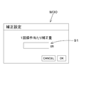
- the correction switch is connected, and the control device controls the automatic steering mechanism, and the control device sets the correction amount of the position of the vehicle based on the number of times of operation of the correction switch.
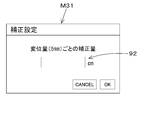
- the control device sets a correction amount of the position of the vehicle based on an operation amount of the correction switch.
- a steering switch is provided to switch between the automatic steering and the manual steering by the steering wheel.
- a work vehicle according to another aspect of the present invention includes a driver's seat and an operation console provided in front of or to the side of the driver's seat, and the operation member is operated in a state of being attached to the operation console It is possible to change the position between the first possible state and the second state which can be operated in the state of being removed from the operation console.
- the operating member is an operating unit attached to the operating console in the first state and removed from the operating console in the second state, and a cord connected to the operating portion in the first state And a cord portion accommodated in the operation console and moving together with the operation portion in the second state.
- the operation unit is located laterally or rearward of the driver's seat in the second state.
- the operation console has a recess in which the operation unit is mounted, and a cover that accommodates the cord when the operation unit is mounted in the recess.
- the operation member has a notification unit that notifies that the operation is recommended.
- the work vehicle includes a vehicle body and a steering handle for steering the vehicle body, and the operation member steers the vehicle body separately from the steering wheel.
- the work vehicle includes a vehicle body, a steering handle for steering the vehicle body, and a positioning device provided on the vehicle body and capable of detecting the position of the vehicle body based on a signal of a positioning satellite, and the operation member is A correction switch for instructing correction of the position of the vehicle body detected by the positioning device.
- a steering device is provided which steers the vehicle based on a correction position which is a position of the vehicle corrected by the operation of the correction switch and a planned travel line.
- a work vehicle includes a vehicle body, a steering handle for steering the vehicle body, and a positioning device provided on the vehicle body and detecting the position of the vehicle body based on a signal of a positioning satellite.
- An automatic steering mechanism that automatically steers the steering of the vehicle separately from the manual steering by the steering wheel based on the position of the vehicle detected by the positioning device, and correction of the position of the vehicle detected by the positioning device
- a correction switch capable of setting an amount
- a control device capable of controlling automatic steering of the automatic steering mechanism and capable of changing a correction amount in a predetermined operation of the correction switch.
- the automatic steering mechanism automatically steers the vehicle body based on a corrected vehicle body position which is a position of the vehicle body corrected based on the correction amount and a planned travel line.
- a travel device having a first wheel provided on one side in the width direction of the vehicle body and a second wheel provided on the other side in the width direction of the vehicle body, and any of the first wheel and the second wheel And a braking device capable of braking the first wheel and the first wheel to eliminate the deviation when the deviation between the position of the vehicle body and the planned travel line is equal to or greater than a predetermined value. Brake one of the two wheels.
- the positioning device detects an inertia of the vehicle body, and an inertial measurement device that corrects the position of the vehicle body based on the detected inertia, and a display device that displays that the drift amount of the inertial measurement device has become a predetermined value or more. And a reset switch for resetting the inertial measurement device.
- the work device includes a work device provided on the vehicle body and capable of changing the work width, and the work device changes the position of the work device based on the deviation between the position of the vehicle body and the planned travel line.
- the work vehicle is provided with a steering selector switch that instructs the start and end of the automatic steering, and the automatic steering mechanism controls the rotation of the steering motor that can rotate a steering post that supports the steering wheel, and the steering motor And a cutoff switch that is connected to the power supply line of the control device that performs the automatic steering and that can switch between a cutoff position that shuts off the power supply line and a conduction position that energizes the power supply line;
- the switch is switched to the energized position when the steering selector switch is instructed to start the automatic steering, and the steering selector switch is instructed to end from the command to start the automatic steering. Switches to the blocking position.
- the work vehicle is provided with a steering selector switch that switches between the start and the end of the automatic steering, and the control device is configured to automatically switch the start of the automatic steering by the steering selector switch. Start steering.
- the work vehicle includes a positioning device capable of detecting the position of the vehicle body, and a reference line setting switch for setting the position of the vehicle body detected by the positioning device to the start position and the end position of the traveling reference line. .
- the vehicle body can be steered not only by steering the vehicle body by manual steering with the steering wheel but also by either a pressing operation or a slide operation by the steering switch. Further, even when steering or the like is performed using the position of the vehicle body detected by the position detection device, the influence of detection accuracy by the position detection device can be reduced.
- the operability of the operation member can be improved. Further, according to the work vehicle described above, the position can be easily corrected in the automatic steering.
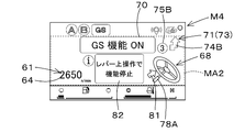
- FIG. 7 is a diagram showing a driving screen M2 when the correction amount on the left side of the vehicle body is set at the time of automatic steering.
- FIG. 7 is a view showing a driving screen M2 when the correction amount on the right side of the vehicle body is set at the time of automatic steering.
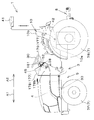
- FIG. 20 is a side view of the work vehicle 1
- FIG. 20 is a plan view of the work vehicle 1.
- the work vehicle 1 is a tractor.
- the work vehicle 1 is not limited to a tractor, and may be an agricultural machine (agricultural vehicle) such as a combine or a transplant machine, or a construction machine (a construction vehicle) such as a loader work machine.
- the front side (direction of arrow A1 in FIG. 20) of the driver sitting in the driver's seat 10 of the tractor (work vehicle) 1 is forward
- the rear side of the driver (direction of arrow A2 in FIG. 20) is rear
- the left side of the driver (The direction of arrow B1 in FIG. 20) will be described as the left
- the right side of the driver (the direction of arrow B2 in FIG. 20) as the right.
- a horizontal direction (direction of arrow B3 in FIG. 20) which is a direction orthogonal to the front-rear direction of the work vehicle 1 will be described as the vehicle body width direction.
- the tractor 1 includes a vehicle body 3, a motor 4 and a transmission 5.
- the vehicle body 3 has a traveling device 7 and can travel.
- the traveling device 7 is a device having a front wheel 7F and a rear wheel 7R.
- the front wheel 7F may be a tire type or a crawler type.
- the rear wheel 7R may also be of a tire type or a crawler type.
- the prime mover 4 is a diesel engine, an electric motor or the like, and in this embodiment, is constituted by a diesel engine.
- the transmission 5 can switch the propulsive force of the traveling device 7 by shifting, and can switch between forward and reverse traveling of the traveling device 7.
- a driver's seat 10 is provided on the vehicle body 3.
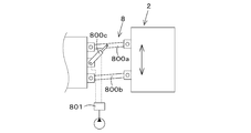
- a connecting portion 8 constituted by a three-point link mechanism or the like is provided at the rear of the vehicle body 3.
- the working device can be attached to and detached from the connecting portion 8.
- the work device can be pulled by the vehicle body 3 by connecting the work device to the connecting portion 8.
- Working equipment includes tillage equipment for cultivating, fertilizer application equipment for applying fertilizer, pesticide application apparatus for applying pesticides, harvesting apparatus for harvesting, harvesting apparatus for harvesting grass, etc., diffusion apparatus for spreading grass, etc., grass Such as a grass collecting apparatus for collecting grass and the like, and a molding apparatus for molding grass and the like.
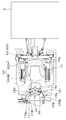
- the transmission 5 includes a main shaft (promotion shaft) 5a, a main transmission unit 5b, an auxiliary transmission unit 5c, a shuttle unit 5d, a PTO power transmission unit 5e, and a front transmission unit 5f. Is equipped.
- the propulsion shaft 5 a is rotatably supported by a housing case (a transmission case) of the transmission 5, and power from the crankshaft of the motor (engine) 4 is transmitted to the propulsion shaft 5 a.
- the main transmission unit 5 b includes a plurality of gears and a shifter that changes the connection of the gears.
- the main transmission unit 5b changes and outputs the rotation input from the propulsion shaft 5a by changing the connection (meshing) of the plurality of gears appropriately with a shifter.
- the auxiliary transmission unit 5c includes a plurality of gears and a shifter that changes the connection of the gears.
- the auxiliary transmission unit 5 c changes and outputs the rotation input from the main transmission unit 5 b by appropriately changing the connection (meshing) of the plurality of gears with a shifter.
- the shuttle unit 5 d has a shuttle shaft 12 and a forward / reverse switching unit 13.
- the power output from the auxiliary transmission unit 5c is transmitted to the shuttle shaft 12 via a gear or the like.
- the forward and reverse travel switching unit 13 is formed of, for example, a hydraulic clutch, and switches the rotational direction of the shuttle shaft 12, that is, forward and reverse travel of the tractor 1 by turning on and off the hydraulic clutch.
- the shuttle shaft 12 is connected to the rear wheel differential device 20R.
- the rear wheel differential device 20R rotatably supports a rear axle 21R to which the rear wheel 7R is attached.
- the PTO power transmission unit 5 e has a PTO propulsion shaft 14 and a PTO clutch 15.
- the PTO propulsion shaft 14 is rotatably supported and can transmit power from the propulsion shaft 5a.
- the PTO propulsion shaft 14 is connected to the PTO shaft 16 via a gear or the like.
- the PTO clutch 15 is formed of, for example, a hydraulic clutch etc., and does not transmit the power of the propulsion shaft 5a to the PTO propulsion shaft 14 and the state of transmitting the power of the propulsion shaft 5a to the PTO propulsion shaft 14 by turning on and off the hydraulic clutch Switch to the state.
- the front transmission portion 5 f has a first clutch 17 and a second clutch 18.
- the first clutch 17 and the second clutch can transmit the power from the propulsion shaft 5a.
- the power of the shuttle shaft 12 is transmitted via the gear and the transmission shaft.
- the power from the first clutch 17 and the second clutch 18 can be transmitted to the front axle 21F via the front transmission shaft 22.
- the front transmission shaft 22 is connected to the front wheel differential device 20F, and the front wheel differential device 20F rotatably supports a front axle 21F to which the front wheel 7F is attached.
- the first clutch 17 and the second clutch 18 are configured by hydraulic clutches and the like.
- An oil passage is connected to the first clutch 17, and the oil passage is connected to a first operation valve 25 to which hydraulic fluid discharged from a hydraulic pump is supplied.
- the first clutch 17 switches between the connected state and the disconnected state according to the degree of opening of the first actuating valve 25.
- An oil passage is connected to the second clutch 18, and the oil passage is connected to a second operation valve 26.
- the second clutch 18 switches between the connected state and the disconnected state according to the degree of opening of the second operating valve 26.
- the first operating valve 25 and the second operating valve 26 are, for example, two-position switching valves with solenoid valves, and are switched to the connected state or the disconnected state by exciting or demagnetizing solenoids of the solenoid valves.
- the tractor 1 is provided with a braking device.
- the braking system has a left braking system 46a and a right braking system 46b.
- the left braking device 46a and the right braking device 46b are disk-type braking devices, and can be switched between a braking state in which braking is performed and a releasing state in which the braking is released.
- the left braking device 46a is provided on the left side of the rear axle 21R
- the right braking device 46b is provided on the right side of the rear axle 21R.
- a left brake pedal and a right brake pedal are provided in the vicinity of the driver's seat 10.
- the left connecting member 47a connected to the left brake pedal can move in the braking direction, and the left braking device 46a can be put into the braking state.
- the right connecting member 47b connected to the right brake pedal can move in the braking direction, and the right braking device 46b can be put into the braking state.
- a left hydraulic actuation unit 48a actuated by hydraulic fluid is coupled to the left coupling member 47a.
- a third operation valve (left brake valve) 49a is connected to the left hydraulic operation unit 48a via an oil passage.
- the left connecting member 47a can be moved in the braking direction by operating the left hydraulic operating portion 48a by the third operation valve 49a.
- a right hydraulic operating unit 48b operated by hydraulic fluid is connected to the right connecting member 47b.
- a fourth operation valve (right brake valve) 49b is connected to the right hydraulic operation unit 48b via an oil passage. The right connecting member 47b can be moved in the braking direction by operating the right hydraulic operating unit 48b by the fourth operation valve 28b.
- the tractor 1 includes a position detection device 40 (also referred to as a positioning device).
- the position detection device 40 is a device that detects its own position (positioning information including latitude and longitude) by a satellite positioning system (positioning satellite) such as D-GPS, GPS, GLONASS, Hokuto, Galileo, Michibiki and the like.
- the position detection device 40 receives the received signal (position of positioning satellite, transmission time, correction information, etc.) transmitted from the positioning satellite, and based on the received signal (also referred to as satellite signal), the position (eg, latitude, Detect longitude).
- the position detection device 40 includes a reception device 41 and an inertial measurement unit (IMU).
- the receiving device 41 has an antenna or the like and receives a received signal transmitted from a positioning satellite, and is attached to the vehicle body 3 separately from the inertial measurement device 42. In this embodiment, the receiving device 41 is attached to a rope provided on the vehicle body 3.
- the attachment location of the receiver 41 is not limited to embodiment.
- the inertial measurement device 42 includes an acceleration sensor that detects an acceleration, a gyro sensor that detects an angular velocity, and the like.
- a roll angle, a pitch angle, a yaw angle, and the like of the vehicle body 3 can be detected by the inertial measurement device 42 provided below the vehicle body 3, for example, the driver's seat 10.
- the tractor 1 includes a steering device 11.
- the steering device 11 is a device capable of performing a manual steering that steers the vehicle body 3 by a driver's operation and an automatic steering that automatically steers the vehicle 3 regardless of the driver's operation.
- the steering device 11 includes a steering handle (steering wheel) 30 and a steering shaft (rotational shaft) 31 that rotatably supports the steering handle 30.
- the steering device 11 also has an auxiliary mechanism (power steering device) 32.
- the auxiliary mechanism 32 assists the rotation of the steering shaft 31 (steering handle 30) by hydraulic pressure or the like.
- the auxiliary mechanism 32 includes a hydraulic pump 33, a control valve 34 to which hydraulic fluid discharged from the hydraulic pump 33 is supplied, and a steering cylinder 35 operated by the control valve 34.
- the control valve 34 is, for example, a three-position switching valve that can be switched by the movement of a spool or the like, and switches according to the steering direction (rotational direction) of the steering shaft 31.
- the steering cylinder 35 is connected to an arm (knuckle arm) 36 that changes the direction of the front wheel 7F.
- the switching position and the opening degree of the control valve 34 are switched corresponding to the rotation direction of the steering handle 30, and the control valve 34 is switched.
- the steering direction of the front wheel 7F can be changed by the steering cylinder 35 extending or contracting to the left or right depending on the switching position and the opening degree of the front wheel 7F. That is, the vehicle body 3 can change the traveling direction to the left or right by the manual steering of the steering wheel 30.
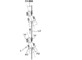
- the traveling reference line L1 is set before performing the automatic steering.
- Automatic steering can be performed by setting the planned traveling line L2 parallel to the traveling reference line L1 after setting the traveling reference line L1.
- the steering of the traveling direction of the tractor 1 is automatically performed so that the vehicle position measured by the position detection device 40 and the planned traveling line coincide with L2.
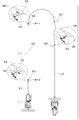
- the tractor 1 (vehicle body 3) is moved to a predetermined position in the field before automatic steering (S1), and the driver operates the steering selector switch 52 provided on the tractor 1 at the predetermined position. If it is performed (S2), the vehicle body position measured by the position detection device 40 is set to the start point P10 of the traveling reference line L1 (S3). Also, when the tractor 1 (vehicle body 3) is moved from the start point P10 of the travel reference line L1 (S4) and the driver operates the steering selector switch 52 at a predetermined position (S5), the position detection device 40 measures The vehicle body position is set to the end point P11 of the traveling reference line L1 (S6). Therefore, a straight line connecting the start point P10 and the end point P11 is set as the travel reference line L1.
- a planned travel line L2 which is a straight line parallel to the travel reference line L1 is set (S9).
- the traveling speed (vehicle speed) of the tractor 1 allows the driver to manually change the operation amount of the accelerator member (accelerator pedal, accelerator lever) provided on the tractor 1, or The change can be made by changing the speed position of the transmission.
- the automatic steering can be ended. That is, the end point of the planned travel line L2 can be set by the end of the automatic steering by the operation of the steering change switch 52. That is, the length from the start point to the end point of the planned travel line L2 can be set longer or shorter than the travel reference line L1. In other words, the planned travel line L2 is not associated with the length of the travel reference line L1, and the travel planned line L2 can travel while automatically steering a distance longer than the length of the travel reference line L1.
- the steering device 11 has an automatic steering mechanism 37.
- the automatic steering mechanism 37 is a mechanism that performs automatic steering of the vehicle body 3, and automatically steers the vehicle body 3 based on the position (vehicle body position) of the vehicle body 3 detected by the position detection device 40.
- the automatic steering mechanism 37 includes a steering motor 38 and a gear mechanism 39.
- the steering motor 38 is a motor whose rotational direction, rotational speed, rotational angle, etc. can be controlled based on the vehicle position.
- the gear mechanism 39 includes a gear provided on the steering shaft 31 and rotating with the steering shaft 31, and a gear provided on the rotation shaft of the steering motor 38 and rotating with the rotation shaft.
- the tractor 1 includes a display device 45.
- the display device 45 is a device capable of displaying various information related to the tractor 1, and can display at least operation information of the tractor 1.
- the display device 45 is provided in front of the driver's seat 10.
- the tractor 1 includes a setting switch 51.
- the setting switch 51 is a switch for switching to a setting mode for performing setting at least before the start of the automatic steering.
- the setting mode is a mode in which various settings regarding the automatic steering are performed before starting the automatic steering, and for example, a mode in which the start point and the end point of the traveling reference line L1 are set.
- the setting switch 51 can be switched to ON or OFF, and outputs a signal indicating that the setting mode is valid if it is ON, and outputs a signal indicating that the setting mode is invalid if it is OFF.
- a signal indicating that the setting mode is valid is output to the display device 45.
- the setting switch 51 is indicating OFF, a signal indicating that the setting mode is invalid is output to the display device 45.
- the tractor 1 is provided with a steering change switch 52.
- the steering changeover switch 52 is a switch for switching the start or end of the automatic steering. Specifically, the steering changeover switch 52 can be switched from the neutral position up, down, front and back, and when the setting mode is in effect, automatic steering is started when switched from the neutral position to the lower side. It outputs, and when it is switched from the neutral position to the upper side in the state where the setting mode is effective, the end of the automatic steering is output. Further, when the steering mode switch 52 is switched from the neutral position later in a state where the setting mode is effective, the steering mode switch 52 outputs that the current vehicle position is set to the start point P10 of the traveling reference line L1. When the setting mode is switched to the previous position from the neutral position in the state where the setting mode is effective, setting of the current vehicle position to the end point P11 of the traveling reference line L1 is output.
- the steering selector switch 52 doubles as a reference line setting switch for setting the start position (start point P10) and the end position (end point P11) of the travel reference line L1.
- the steering selector switch 52 may be configured separately from the steering selector switch 52 that switches the start or end of automatic steering and the reference line setting switch.
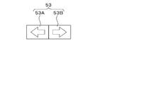
- the tractor 1 is provided with a correction switch 53.
- the correction switch 53 is a switch that corrects the vehicle body position (latitude, longitude) measured by the position detection device 40. That is, the correction switch 53 is a vehicle position (computed vehicle position) calculated by the received signal (position of positioning satellite, transmission time, correction information, etc.) and measurement information (acceleration, angular velocity) measured by the inertial measurement device 42. ) Is a switch that corrects
- the correction switch 53 is configured of a pushable push switch or a slidable slide switch.
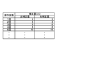
- the correction amount is set based on the number of operations of the push switch.
- the number of times of operation of the push switch is input to the first control device 60A, and the first control device 60A sets (calculates) the correction amount based on the number of times of operation.
- the first control device 60A can change the predetermined operation of the push switch, that is, the correction amount per one operation.
- the correction amount is set based on the operation amount (displacement amount) of the slide switch.
- the operation amount (displacement amount) of the slide switch is input to the first control device 60A, and the first control device 60A sets (calculates) the correction amount based on the displacement amount. Even if the correction switch 53 is a slide switch, the correction amount can be changed in the same manner as the push switch. Further, the method of increasing the amount of correction and the rate of increase described above are not limited to the values described above.
- the correction switch 53 includes a first correction unit 53A and a second correction unit 53B.
- the first correction unit 53A is a part that instructs correction of the vehicle body position corresponding to one side in the width direction of the vehicle body 3, that is, the left side.
- the second correction unit 53B is a part that instructs the correction of the vehicle body position corresponding to the other side in the width direction of the vehicle body 3, that is, the right side.
- the correction switch 53 when the correction switch 53 is a push switch, the first correction unit 53A and the second correction unit 53B are ON or OFF switches that automatically return each time an operation is performed.
- the switch constituting the first correction unit 53A and the switch constituting the second correction unit 53B are integrated.
- the switch that constitutes the first correction unit 53A and the switch that constitutes the second correction unit 53B may be arranged separately from each other.
- FIG. 3A each time the first correction portion 53A is pressed, the correction amount (left correction amount) corresponding to the left side of the vehicle body 3 increases.
- the second correction unit 53B is pressed, the correction amount (right correction amount) corresponding to the right side of the vehicle body 3 increases.
- the first correction unit 53A and the second correction unit 53B include a knob 55 that moves left or right along the longitudinal direction of the long hole. There is.
- the first correction unit 53A and the second correction unit 53B are disposed apart from each other in the width direction.
- the knob 55 when the knob 55 is gradually displaced to the left from a predetermined reference position, the left correction amount increases according to the displacement amount.
- the knob 55 when the knob 55 is gradually displaced to the right from a predetermined reference position, the right correction amount increases according to the displacement amount.
- FIG. 3B when the knob 55 is gradually displaced to the left from a predetermined reference position, the left correction amount increases according to the displacement amount.
- the knob 55 is gradually displaced to the right from a predetermined reference position, the right correction amount increases according to the displacement amount.
- the first correction unit 53A and the second correction unit 53B are integrally formed, the reference position of the knob 55 is set at the center, and from the reference position
- the left correction amount may be set when moving to the left
- the right correction amount may be set when moving the knob 55 from the intermediate position to the right.
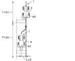
- FIG. 5A shows a state in which the calculated vehicle body position W1 is shifted to the right while traveling straight during automatic steering.
- the actual position (actual position W2) of the tractor 1 matches the calculated vehicle position W1 and the actual position W2 and the planned travel line
- L2 matches, the tractor 1 travels along the planned travel line L2.
- the tractor 1 follows the planned travel line L2 in the section P1 in which there is no error in the positioning of the position detection device 40 and the vehicle position (computed vehicle position W1) detected by the position detection device 40 is the same as the actual position W2. Run.
- the calculated vehicle body position W1 and the corrected vehicle position (corrected vehicle position) W3 corrected by the correction amount have the same value.
- the position detection device 40 Assuming that the detected vehicle position deviates to the right with respect to the planned travel line L2 (actual position W2) and the deviation amount W4 is maintained, the tractor 1 deviates between the calculated vehicle body position W1 and the planned travel line L2. Is determined, and the tractor 1 is steered to the left so as to eliminate the deviation amount W4 between the calculated vehicle body position W1 and the planned travel line L2. Then, the actual position W2 of the tractor 1 is shifted to the planned travel line L2 by the left steering.
- the driver notices that the tractor 1 deviates from the planned travel line L2, and steers the second correction unit 53B at the position P21 to increase the right correction amount from zero.
- the right correction amount is added to the calculated vehicle position W1, and the corrected vehicle position (corrected vehicle position) W3 can be made substantially the same as the actual position W2. That is, by setting the right correction amount by the second correction unit 53B, it is possible to correct the vehicle position of the position detection device 40 in the direction of eliminating the displacement amount W4 generated near the position P20.
- the tractor 1 is steered to the right.
- the actual position W2 can be made to coincide with the planned travel line L2.
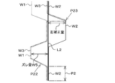
- FIG. 5B shows a state in which the calculated vehicle body position W1 is shifted to the left while traveling straight during automatic steering.
- the configuration shown in FIG. 5B in the case where the actual position W2 matches the calculated vehicle body position W1 and the actual position W2 matches the planned travel line L2 in the state where the automatic steering is started, the configuration shown in FIG. Similarly, the tractor 1 travels along the planned travel line L2. That is, as in FIG. 5A, the tractor 1 travels along the planned travel line L2 in the section P2 in which there is no error in the positioning of the position detection device 40. Further, as in FIG. 5A, the calculated vehicle body position W1 and the corrected vehicle body position W3 have the same value.
- the tractor 1 steers the tractor 1 to the right so as to eliminate the amount of deviation W5 between the calculated vehicle body position W1 and the planned travel line L2. Thereafter, it is assumed that the driver notices that the tractor 1 deviates from the planned travel line L2, and the driver steers the first correction unit 53A at the position P23 to increase the left correction amount from zero. Then, the left correction amount is added to the calculated vehicle position W1, and the corrected vehicle position (corrected vehicle position) W3 can be made substantially the same as the actual position W2.
- the correction switch 53 is also a steering member for steering the vehicle body 3.
- the setting switch 51, the correction switch 53, and the screen changeover switch 54 will be described.
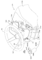
- an operation console 150 is provided in front of the driver's seat 10.
- the operation table 150 is a table which supports at least an operation member for performing an operation, and a correction switch 53 which is one of the operation members is attached. Further, a setting switch 51 and a steering changeover switch 52 are attached to the operation console 150.
- the operation console 150 supports a steering handle 30, that is, a steering shaft (rotational shaft) 31 that rotatably supports the steering handle 30.
- the outer periphery of the steering shaft 31 is covered by a steering post 180.
- the outer periphery of the steering post 180 is covered by a cover 177. That is, the operation console 150 includes a cover 177 that covers the steering shaft (rotational shaft) 31.
- the cover 177 is provided in front of the driver's seat 10.
- the cover 177 includes a panel cover 178 and a column cover 179.
- the panel cover 178 supports the display device 45.
- the upper plate portion 178 a of the panel cover 178 is provided with a support portion 178 e for supporting the display device 45.
- the support portion 178 e supports the display device 45 in front of the steering shaft 31 and below the steering handle 30.
- the upper plate portion 178a has a mounting surface 178f to which the setting switch 51, the correction switch 53, and the screen switching switch 54 are attached.
- the mounting surface 178 f is provided behind the support portion 178 e and below the steering handle 30.
- the support portion 178e and the mounting surface 178f are continuous, the support portion 178e is located at the front of the upper plate portion 178a, and the mounting surface 178f is located at the rear of the upper plate portion 178a.
- the setting switch 51, the correction switch 53, and the screen switching switch 54 are attached to the mounting surface 178f.
- the setting switch 51, the correction switch 53, and the screen switching switch 54 are disposed around the steering shaft 31.
- a shuttle lever 181 projects from the left plate portion 178 b of the panel cover 178.
- the shuttle lever 181 is a member for switching the traveling direction of the vehicle body 3. More specifically, by operating (swinging) the shuttle lever 181 forward, the forward / reverse switching unit 13 outputs a forward power to the traveling device 7, and the traveling direction of the vehicle body 3 is switched to the forward direction. Further, by operating (swinging) the shuttle lever 181 rearward, the forward / reverse switching unit 13 outputs a reverse power to the traveling device 7, and the traveling direction of the vehicle body 3 is switched to the backward direction. When the shuttle lever 181 is in the neutral position, power is not output to the traveling device 7.
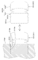
- the column cover 179 is disposed below the steering handle 30 and covers the periphery of the upper portion of the steering shaft 31.
- the column cover 179 is formed in a substantially square cylindrical shape and protrudes upward from the mounting surface 178 f of the panel cover 178. That is, the mounting surface 178 f is provided around the column cover 179. Therefore, the setting switch 51, the correction switch 53, and the screen switching switch 54 attached to the mounting surface 178f are disposed around the column cover 179.
- the setting switch 51, the steering switch 52, the correction switch 53, and the screen switch 54 are disposed around the steering shaft 31.
- the setting switch 51 is disposed on one side (left side) of the steering shaft 31.
- the steering changeover switch 52 is disposed on one side (left side) of the steering shaft 31.
- the steering changeover switch 52 is composed of a pivotable lever.
- the steering changeover switch 52 is pivotable about a base end provided on the steering shaft 31 side.
- the base end of the steering selector switch 52 is provided inside the column cover 179.
- the steering changeover switch 52 protrudes to one side (left side) of the column cover 179.
- the correction switch 53 is disposed on the other side (right side) of the steering shaft 31. More specifically, the correction switch 53 is disposed to the right and to the rear of the steering shaft 31 (oblique right rear). The correction switch 53 is disposed on the right side and the rear (diagonal right rear) of the column cover 179 in the positional relationship with the column cover 179. The correction switch 53 is disposed at the right rear of the mounting surface 178f in positional relationship with the mounting surface 178f of the panel cover 178. By arranging the correction switch 53 at the rear of the inclined mounting surface 178f, a long distance between the correction switch 53 and the steering wheel 30 can be secured. Thereby, the operation of the correction switch 53 and the steering of the steering wheel 30 which are not intended can be prevented more reliably.
- the screen switching switch 54 is disposed on the other side (right side) of the steering shaft 31. More specifically, the screen switching switch 54 is disposed on the right side and in front of the steering shaft 31 (diagonal right front). The screen switching switch 54 is disposed on the right side and in front of the column cover 179 (diagonal right front) in the positional relationship with the column cover 179. The screen switching switch 54 is disposed on the right front of the mounting surface 178 f in positional relationship with the mounting surface 178 f of the panel cover 178. The screen switching switch 54 is disposed in front of the correction switch 53.
- the setting switch 51, the steering changeover switch 52, the correction switch 53, and the screen changeover switch 54 are disposed around the steering shaft 31.
- the setting switch 51, the steering changeover switch 52, the correction switch 53, and the screen changeover switch 54 are collectively present around the steering shaft 31. Therefore, the driver can grasp the position of each switch at a glance.
- the driver can operate each switch without changing the posture while sitting on the driver's seat 10. Therefore, operability can be improved and erroneous operation can be prevented.
- the harnesses (wirings) arranged from each switch can be shortened.
- left and right may be interchanged. That is, one side may be left and the other side may be right, or one side may be right and the other side may be left.
- the setting switch 51 and the steering changeover switch 52 may be disposed to the right of the steering shaft 31, and the correction switch 53 may be disposed to the left of the steering shaft 31.
- the tractor 1 is provided with a plurality of control devices 60.
- the plurality of control devices 60 are devices that perform control of a traveling system in the tractor 1, control of a working system, calculation of a vehicle position, and the like.
- the plurality of control devices 60 are a first control device 60A, a second control device 60B, and a third control device 60C.
- the first control device 60A receives the reception signal (reception information) received by the reception device 41 and the measurement information (acceleration, angular velocity, etc.) measured by the inertia measurement device 42, and the vehicle position based on the reception information and the measurement information.
- the first control device 60A calculates the calculated vehicle body by the reception information and the measurement information. The correction is not performed on the position W1, and the calculated vehicle body position W1 is determined to be the vehicle body position used at the time of automatic steering.
- the first control device 60A determines the vehicle position based on either the number of operations of the correction switch 53 or the operation amount (displacement amount) of the correction switch 53. A correction amount is set, and a corrected vehicle body position W3 obtained by correcting the calculated vehicle body position W1 with the correction amount is determined as the vehicle body position used at the time of automatic steering.
- the first control device 60A sets a control signal based on the vehicle position (the calculated vehicle position W1, the corrected vehicle position W3) and the planned travel line L2, and outputs the control signal to the second control device 60B.
- the second control device 60 ⁇ / b> B includes an automatic steering control unit 200.
- the automatic steering control unit 200 is configured by an electric / electronic circuit provided in the second control device 60B, a program stored in a CPU, and the like.
- the automatic steering control unit 200 controls the steering motor 38 of the automatic steering mechanism 37 so that the vehicle body 3 travels along the planned travel line L2 based on the control signal output from the first control device 60A. Control. As shown in FIG. 17, when the deviation between the vehicle position and the planned travel line L2 is less than the threshold value, the automatic steering control unit 200 (second control device 60B) maintains the rotation angle of the rotation shaft of the steering motor 38. .
- the automatic steering control unit 200 (second control device 60B) rotates the rotation shaft of the steering motor 38 such that the steering direction of the tractor 1 is in the right direction. That is, the automatic steering control unit 200 sets the steering angle in the right direction so that the position deviation becomes zero.
- the second control device 60B causes the steering direction of the tractor 1 to be left
- the rotation shaft of the steering motor 38 is rotated to be in the direction. That is, the automatic steering control unit 200 sets the steering angle in the left direction so that the position deviation becomes zero.
- the steering angle of the steering device 11 is changed based on the deviation between the vehicle position and the planned travel line L2, but the direction of the planned travel line L2 and the traveling direction of the tractor 1 (vehicle body 3) If the direction (vehicle direction) F1 of (travel direction) is different, that is, if the angle ⁇ of the vehicle direction F1 with respect to the planned travel line L2 is equal to or greater than the threshold, the automatic steering control unit 200 (second control device 60B) The steering angle may be set such that the angle ⁇ is zero (the vehicle direction F1 matches the direction of the planned travel line L2).
- the automatic steering control unit 200 (the second control device 60B) is based on the steering angle determined based on the deviation (positional deviation) and the steering angle determined based on the azimuth (azimuth deviation ⁇ ).
- the final steering angle in automatic steering may be set.
- the setting of the steering angle in the automatic steering in the embodiment described above is an example and is not limited.
- the third control device 60 ⁇ / b> C raises and lowers the connecting portion 8 in accordance with the operation of the operation member provided around the driver's seat 10.
- the first control device 60A, the second control device 60B, and the third control device 60C may be integrated. Further, the control of the traveling system, the control of the working system, and the calculation of the vehicle body position described above are not limited. As described above, the control device 60 can automatically steer the tractor 1 (vehicle body 3).
- the steering selector switch 52 when switching to the start of automatic steering is performed, energization to the second control device 60B is performed, and when switching to the end of automatic steering is performed, energization to the second control device 60B is performed. You may not do this.
- the setting relating to the travel of the vehicle body 3 can be performed by the display device 45. Hereinafter, the details of the display device 45 will be described.
- the display device 45 can acquire various information detected by the detection device 47 via an in-vehicle network or the like.
- the detection device 47 is an accelerator pedal sensor, shift lever detection sensor, crank position sensor, fuel sensor, water temperature sensor, motor rotation sensor, steering angle sensor, oil temperature sensor, axle rotation sensor, and the like.
- the display device 45 can display, as operation information, the remaining amount of fuel detected by the fuel sensor, the water temperature value detected by the water temperature sensor, the number of revolutions of the motor, etc. detected by the motor rotation sensor.
- the display device 45 can acquire information of various switches, for example, information of the setting switch 51, the steering switch 52, and the correction switch 53.
- the display device 45 acquires information of ON or OFF of the setting switch 51, information of start and end of automatic steering in the steering changeover switch 52, and information of commands of the start point P10 and end point P11 of the travel reference line L1 in the steering changeover switch 52. can do.
- the display device 45 includes a display unit 46 that displays various information.
- the display unit 46 includes a fixed display unit 46A that displays a warning and the like, and a variable display unit 46B that can change information to be displayed.
- the fixed display unit 46A includes a panel in which a graphic such as a warning is shown, and an irradiation unit such as an LED that irradiates a light source to the graphic on the panel.
- the variable display unit 46B is configured of a panel such as an organic EL, a liquid crystal, etc., and displays various information related to the operation (traveling) of the tractor 1 and the like.
- FIG. 6A shows an operation screen M1 of the tractor 1.
- the operation screen M1 is a screen displayed on the variable display unit 46B when the setting switch 51 is OFF, that is, when the setting mode is invalid.
- the display device 45 that is, the driving screen M1 has a driving display unit 61 that shows driving information.
- the operation display unit 61 includes a rotation display unit 62 that displays the number of rotations of the motor 4 (motor rotation speed) as the operation information.
- the rotation display unit 62 includes a level display unit 63.
- the level display unit 63 is a part that displays the motor rotation speed in stages.
- the level display unit 63 includes a scale unit 65 and an indicator unit 80.
- the scale unit 65 includes, for example, a first line 65A and a plurality of second lines 65B assigned at predetermined intervals along the first line 65A. Moreover, the scale part 65 has the 1st line 65A and the 3rd line 65C spaced apart by predetermined spacing.
- the first line 65A and the third line 65C are formed in, for example, a semicircular shape, with one end side (for example, the left side) being the minimum value and the other end side (for example the right side) being the maximum value .
- the index unit 80 is a bar whose length changes in accordance with the size of the motor rotation speed.
- the index unit 80 is positioned between the first line 65A and the third line 65C, and when the value of the motor rotation speed is the minimum value of zero, the index unit 80 of the first line 65A and the third line 65C.
- the length is the shortest and the value of the motor rotation speed is the maximum value located at one end side (left side), the first line 65A and the first line 65A from one end side (left side) of the first line 65A and the third line 65C. It extends to the other end side (right side) of the third line 65C and has the longest length.
- the rotation display unit 62 includes a number display unit 64.
- the numeral display unit 64 displays the number of revolutions of the motor as a number.
- the rotary display unit 62 is disposed inside the semicircle of the first line 65A and the third line 65C.
- the motor display rotational speed such as the engine rotational speed can be displayed stepwise by the level display unit 63 and can be displayed by the numerical display by the rotational display unit 62.
- the driving screen M1 includes an icon display unit 67 that displays a plurality of icon units 66.
- the icon display unit 67 is a portion that shows various information by the icon unit 66. That is, the setting regarding traveling such as automatic steering, for example, the setting state set in the setting mode is displayed by the icon section 66.
- the icon display unit 67 is disposed at a position different from that of the operation display unit 61, for example, at the upper part of the operation screen M1.
- the plurality of icon portions 66 include a first icon portion 66A, a second icon portion 66B, a third icon portion 66C, a fourth icon portion 66D, a fifth icon portion 66E, a sixth icon portion 66F, a seventh icon portion 66G, 8 icon part 66H.
- the operation screen M1 does not have to include all of the plurality of icon portions 66 (66A, 66B, 66C, 66D, 66E, 66F, 66G, 66H), and is not limited to the above-described embodiment.
- the first icon portion 66A is displayed when a warning occurs.
- the second icon portion 66B is displayed when the start point P10 of the traveling reference line L1 is set.
- the third icon portion 66C is displayed when the end point P11 of the traveling reference line L1 is set.
- the fourth icon portion 66D is displayed when the conditions for automatic steering are satisfied. For example, the fourth icon portion 66D is displayed when the setting mode is valid, the setting of the travel reference line L1 is completed, and the planned travel line L2 can be set.
- the fourth icon portion 66D is displayed when the automatic steering is permitted.
- the fourth icon portion 66D is displayed when the setting mode is valid and the setting of the travel reference line L1 is completed.
- the operator can grasp that automatic steering is permitted. Then, the operator can start the automatic steering by operating the steering selector switch 52.
- the fifth icon portion 66E is displayed when the connecting portion 8 is in the elevating state.
- the sixth icon portion 66F is displayed in the 4WD acceleration state.
- the seventh icon portion 66 ⁇ / b> G changes color and the like according to the reception sensitivity of the reception signal of the reception device 41.
- the display of the eighth icon portion 66H changes in accordance with the conditions of the automatic steering. If the eighth icon portion 66H is in a state where the automatic steering can not be performed for some reason, for example, if the setting mode is invalid and the reception sensitivity of the reception signal of the reception device 41 is low and the vehicle position can not be detected, the traveling reference line L1 For example, when the setting is not made, it becomes gray to indicate that automatic steering can not be performed.
- the eighth icon portion 66H When the eighth icon portion 66H is in a state where automatic steering can be performed for some reason, for example, the setting mode is valid, and the reception sensitivity of the reception signal of the reception device 41 can detect the vehicle body position with a predetermined sensitivity or more. When the driving reference line L1 is set, the green color indicates that automatic steering can be performed.
- the display form in the eighth icon portion 66H is not limited to the display form described above.
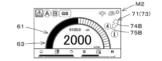
- FIG. 6B shows the operation screen M2 of the tractor 1.
- the operation screen M2 is a screen displayed on the variable display unit 46B when the setting switch 51 is ON, that is, when the setting mode is valid.
- the operation screen M2 also includes the operation display unit 61 and the icon display unit 67.
- the driving screen M2 is a screen capable of displaying the same information as the driving screen M1 at least for the driving information.
- the operation display unit 61 and the icon display unit 67 are the same as the operation screen M1, and the description thereof is omitted.
- the display device 45 changes the display state of the operation display unit 61 of the operation screen M2 to a display mode different from the display state of the operation display unit 61 of the operation screen M1. . That is, when the setting mode is valid, the display device 45 makes the display state of the driving display unit 61 at the time of validation different from the display mode of the driving display unit 61 at the disabling time. The display device 45 sets the color (coloring) indicating the operation display unit 61 in the operation screen M2 to a color different from the color (coloring) indicating the operation display unit 61 in the operation screen M1.
- the display device 45 sets the color of the scale portion 65 of the level display unit 63 in the operation screen M2, that is, the colors of the first line 65A, the second line 65B and the third line 65C to the same color as the operation screen M1. Meanwhile, the color of the indicator portion 80 of the operation screen M2 is different from that of the operation screen M1. That is, when the setting mode is enabled, the color of the index unit 80 is different from the color of the index unit 80 in which the setting mode is disabled.
- the display device 45 sets the color of the numeral display portion 64 in the operation screen M2, that is, the color of the number indicating the motor rotation speed to a color different from that of the operation screen M1. That is, when the setting mode is enabled, the color of the number display unit 64 is different from the color of the number display unit 64 where the setting mode is disabled.
- the setting before the start of the automatic steering can be performed.
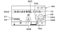
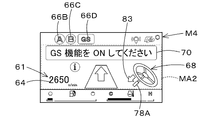
- FIGS. 7A to 7C show the transition of the operation screen M2 at the time of setting the start point P10 and the end point P11 of the travel reference line L1 as the setting before the start of the automatic steering. As shown in FIG.
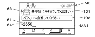
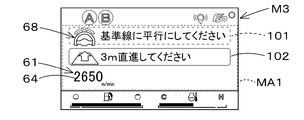
- the display device 45 displays the screen displayed on the variable display portion 46B. Is switched from the operation screen M2 to the guidance screen M3.
- the guidance screen M3 is a screen for displaying an instruction (content) related to traveling of the vehicle body 3.
- the guidance screen M3 is a screen on which settings relating to traveling can be made.
- the guidance screen M3 is a screen for displaying an instruction (content) for adjusting traveling conditions such as automatic steering.
- the guidance screen M3 is a screen for instructing a change in the direction of the vehicle body 3 at least before the start of the automatic steering.
- the direction of the vehicle body 3 Is directed to the right, and as shown in FIG. 9B, it is a screen for instructing to turn the direction of the vehicle body 3 to the left.
- the instruction to turn the vehicle body 3 to the right or to turn the vehicle body 3 to the left is determined by the current traveling direction of the vehicle body 3.
- the traveling direction of the vehicle body 3 can be detected by the position detection device 40.
- the guidance screen M3 directs the vehicle body 3 to the left. Give instructions. Further, as shown in FIG. 8, when the traveling direction of the vehicle body 3 is oblique to the left with respect to the longitudinal direction of the traveling reference line L1, the guidance screen M3 instructs the vehicle 3 to turn to the right. Do.
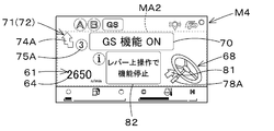
- the guidance screen M3 includes a message display unit 70.
- the message display unit 70 is a portion for explaining the steering of the vehicle body 3 by characters (messages). That is, the message display unit 70 is a portion that indicates the steering direction of the vehicle body 3 with characters as a travel command (content).
- the message display unit 70 displays characters to the effect that the vehicle body 3 is directed to the right.
- the message display unit 70 displays a character to turn the vehicle body 3 to the left.
- the message display unit 70 when maintaining the traveling direction of the vehicle body 3, displays characters to make the vehicle body 3 go straight (straight). As shown in FIG. 9D, the message display unit 70 displays that the straight distance has not reached the predetermined distance when the vehicle 3 needs to be moved straight by the predetermined distance and the straight distance does not reach the predetermined distance. I do. In FIG. 9D, the message display unit 70 may display that the vehicle 3 is allowed to travel straight a predetermined distance.
- the guidance screen M3 includes a steering instruction unit 69.
- the steering instruction unit 69 is a portion that indicates the steering direction of the vehicle body 3. As shown in FIG. 9A, when it is necessary to turn the traveling direction of the vehicle body 3 to the right, the steering instruction unit 69 displays an arrow to turn the traveling direction of the vehicle body 3 to the right. As shown in FIG. 9B, when it is necessary to turn the traveling direction of the vehicle body 3 to the left, the steering instruction unit 69 displays an arrow to turn the traveling direction of the vehicle body 3 to the left. As shown in FIG. 9C, when the traveling direction of the vehicle body 3 is maintained, displaying a pair of arrows facing each other indicates that the vehicle body 3 is made to go straight (straight).
- the guidance screen M3 includes a driving display unit 61 and a steering wheel display unit 68. That is, in the guidance screen M3, the operation display unit 61 and the handle display unit 68 are displayed on the same screen (the same screen). In detail, in the guidance screen M3, the operation display unit 61 and the handle display unit 68 are displayed on the portion (range) MA1 for changing the description.
- the driving display unit 61 in the guidance screen M3 is a part that displays driving information as in the driving screens M1 and M2, and displays at least a part of the driving information indicated by the driving screens M1 and M2.
- the operation display unit 61 in the guidance screen M3 includes a number display unit 64 that indicates the prime mover rotation number by numbers, and displays the engine rotation speed and the like.
- the operation display unit 61 in the guidance screen M3 may include the rotation display unit 62 indicated by the operation screens M1 and M2.
- the operation display unit 61 in the guidance screen M3 may include both of the numeral display unit 64 and the rotation display unit 62 indicated by the operation screens M1 and M2.
- the steering wheel display unit 68 is a portion that shows the steering wheel 30 by a graphic or the like.
- the operation display unit 61 is displayed on one side or the other side of the steering wheel display unit 68.
- the steering wheel display unit 68 and the steering instruction unit 69 are displayed apart from each other.
- the steering wheel display unit 68 and the steering instruction unit 69 may be displayed overlapping each other.
- the handle display unit 68 has a circular grip portion 68A which the driver grips on the steering handle 30, and a connecting portion 68B for connecting the grip portion 68A.
- the steering direction of the steering wheel display unit 68 is changed in accordance with the instruction of the steering direction of the vehicle body 3.
- the steering wheel display unit 68 and the message display unit 70 are displayed on the same screen, that is, the guidance screen M3, the steering direction of the steering wheel display unit 68 is changed according to the steering direction indicated by the message display unit 70. .
- the steering wheel display unit 68 and the steering instruction unit 69 are displayed on the same screen, ie, the guidance screen M3, the steering direction of the steering wheel display unit 68 is changed according to the steering direction indicated by the steering instruction unit 69.
- the guidance screen M3 the steering direction of the steering wheel display unit 68 is indicated by the message display unit 70 and the steering instruction unit 69. It changes according to the steering direction.
- the grip portion 68A and the connecting portion 68B should be rotated right around the center of the grip portion 68A. Indicates that the steering direction is right.
- the handlebar display unit 68 rotates the grip 68A and the connection 68B to the left around the center of the grip 68B. Indicates that the steering direction is left.
- FIG. 9C when the traveling direction of the vehicle body 3 is maintained, it is shown that the steering direction is straight by not rotating the gripping portion 68A and the connecting portion 68B.
- the guidance screen M3 includes a plurality of condition display units indicating traveling conditions.
- the plurality of condition display units are a first condition display unit 101 indicating a first condition and a second condition display unit 102 indicating a second condition.
- a condition display unit indicating two conditions is described as an example, but the number of condition display units is not limited to the embodiment.
- the first condition display unit 101 displays that the traveling direction of the tractor 1 (the vehicle body 3) is made parallel to the traveling reference line L1, for example, “please make it parallel to the reference line” as a condition of automatic steering.
- the second condition display unit 102 displays, for example, “Please go straight ahead by 3 m” as a condition for automatic steering, to make the tractor 1 (vehicle body 3) go straight ahead by a predetermined distance.
- the condition display unit (condition satisfied display unit) in which the traveling condition is satisfied changes the display form with the condition display unit (condition not satisfied display unit) in which the traveling condition is not satisfied. Do. For example, as shown in FIG.
- the first condition display unit The color 101 is colored to a color with low saturation (for example, white, gray, etc.), and the color of the second condition display unit 102 is colored to a color with high saturation.
- the display device 45 sets the saturation of the characters of the condition satisfaction display unit to be lower than the saturation of the characters of the condition non-metition display unit.
- the instruction (contents) for adjusting the traveling conditions of the tractor 1 is displayed, so that the driver can view the instruction shown on the guidance screen M3.
- the tractor 1 vehicle body 3 can be adjusted in traveling conditions. Since driving information is displayed on the guidance screen M3, when traveling of the tractor 1 is necessary to adjust traveling conditions, traveling of the tractor 1 while traveling the tractor 1 while looking at the operating information of the tractor 1 It can be in a state of meeting the conditions. Further, since both the steering wheel display unit 68 and the driving display unit 61 are displayed on the guidance screen M3, for example, the tractor 1 is allowed to travel while grasping both the driving information and the steering direction of the steering wheel 30. Can.
- the display device 45 displays a screen displayed on the variable display portion 46B.
- the guidance screen M3 is returned to the driving screen M2.
- the display device 45 displays the correction amount of the vehicle body position on the driving screen M2.
- the operation display unit 61 in the operation screen M2 includes a correction display unit 71.
- the correction display unit 71 is a portion that displays the correction amount of the vehicle body position as the driving information. That is, the display device 45 displays the correction display unit 71 when the setting mode is valid.
- the number indicated by the correction display unit 71 indicates the number of operations of the correction switch 53, and the correction display unit 71 displays the number of operations as a correction amount.
- the correction display unit 71 includes a first correction display unit 72 and a second correction display unit 73.
- the first correction display unit 72 is a portion that displays the correction amount (left correction amount) of the vehicle body position on one side in the width direction of the vehicle body 3, that is, the left side.
- the second correction display unit 73 is a portion that displays the correction amount (right correction amount) of the vehicle body position on the other side in the width direction of the vehicle body 3, that is, the right side.
- the correction switch 53 When the correction switch 53 is operated, one of the first correction display unit 72 and the second correction display unit 73 is displayed on the operation screen M2.
- the first correction display unit 72 is displayed on the left side of the level display unit 63 when the first correction unit 53A is operated during automatic steering.
- the second correction display unit 73 is displayed on the right side of the level display unit 63 when the second correction unit 53B is operated during automatic steering. That is, the first correction display unit 72 is displayed on the left side corresponding to the first correction unit 53A, and the second correction display unit 73 is displayed on the right side corresponding to the second correction unit 53B.
- the first correction display unit 72 includes an arrow portion 74A and a numerical portion 75A.
- the arrow portion 74A indicates the corrected direction, that is, one side (left side) in the width direction of the vehicle body 3.
- the numerical part 75A indicates the number of operations of the first correction part 53A, and the numerical value is counted up as the number of operations increases.
- the second correction display unit 73 includes an arrow portion 74B and a numerical portion 75B.
- the arrow 74B indicates the corrected direction, that is, the other side (right side) in the width direction of the vehicle body 3.
- the numerical part 75B indicates the number of operations of the second correction part 53B, and the numerical value is counted up as the number of operations increases.
- the correction display unit 71 indicates the magnitude of the correction amount in a stepwise manner by displaying the number of operations as the correction amount, but instead, it indicates the correction amount in stages.
- the lengths of the arrow portions 74A and 74B are changed based on the correction amount of the vehicle body position, or a plurality of levels (index portions) 76 are displayed on the arrow portions 74A and 74B.
- the level 76 may be changed according to the amount of correction.
- the number of display increases as the number of times of operation of the correction switch 53 increases, or the number of display increases as the amount of steering of the correction switch 53 increases.
- the correction display unit 71 may indicate the correction amount itself by a number.
- the screen M3 is displayed, but the screen switching switch 54 is operated when the operation screen M1 is displayed, or the screen switching switch 54 is operated after the operation screen M2 is displayed. It is possible to display such a guidance screen M4.
- the guidance screen M4 is a screen for performing setting relating to traveling, and is a screen for displaying, for example, setting of the traveling reference line L1 and an instruction (content) for adjusting the traveling condition of the vehicle body 3. In other words, the guidance screen M4 is a screen on which navigation for adjusting the traveling conditions can be displayed.
- the guidance screen M4 includes a message display unit 70, an operation display unit 61, and a handle display unit 68. That is, also in the guidance screen M3, the operation display unit 61 and the handle display unit 68 are displayed on the same screen (the same screen).
- the message display unit 70 is a part that displays various commands in characters, and as shown in FIG. 12A, the message display unit 70 turns on the setting switch 51 when the setting mode is set to be invalid. Of, for example, "Please go to GS mode" is displayed. As shown in FIG.
- the message display unit 70 displays a message indicating that the starting point P10 of the traveling reference line L1 is to be set, for example, “Please register the starting point”. . Further, as shown in FIG. 12C, the message display unit 70 displays a message indicating that the start point P10 of the traveling reference line L1 is to be set, for example, "Please register an end point”.
- the operation display unit 61 in the guidance screen M4 is a portion for displaying the operation information, and at least a part of the operation information indicated on the operation screens M1 and M2.
- the operation display unit 61 is displayed on a part (range) MA2 for changing the description.
- the operation display unit 61 in the guidance screen M4 includes a number display unit 64 that indicates the prime mover rotation number by a number, and displays the engine rotation speed and the like.
- the operation display unit 61 in the guidance screen M4 may also include the rotation display unit 62 indicated by the operation screens M1 and M2.
- the operation display unit 61 in the guidance screen M4 may also include both of the numeral display unit 64 and the rotation display unit 62 indicated by the operation screens M1 and M2.
- the handle display unit 68 in the guidance screen M4 also has a gripping unit 68A and a connecting unit 68B.
- the steering wheel display unit 68 in the guidance screen M4 shows a switching display unit 78A in which the steering changeover switch 52 is shown graphically.
- the switching display 78A indicates the operation position when setting the starting point P10 of the traveling reference line L1, and the tip of the switching display 78A is below the grip 68A than the neutral position.
- the switching display unit 78A shows the operation position when setting the end point P11 of the traveling reference line L1, and the tip of the switching display unit 78A is above the neutral position.
- the guidance screen M4 indicates the operation direction of the steering switch 52 corresponding to the switching display portion 78A by the arrow portion 79A.
- a second icon 66B indicating the start point P10 of the travel reference line L1 and an end point P11 of the travel reference line L1 are provided at a position different from the icon display portion 67, ie, at the center in the width direction.
- a third icon portion 66C is displayed.
- a warm-up screen indicating warm-up as shown in FIG. 13 is displayed on the display device 45.
- the display device 45 switches to the guidance screen M4 shown in FIG. 12A.
- the setting of the traveling reference line L1 can be performed with an explanation. That is, although the driving reference line L1 can also be set on the driving screen M2, the display device 45 displays the guidance screen M4 separately from the driving screen M2, so the driver does not know the setting of the automatic steering. However, the driving reference line L1 can be set on the guidance screen M4.
- the operation screen M1 and M2 are switched to the driving screen M1 and M2, respectively.
- the fact that the start point P10 has been set and the end point P11 has been set is displayed by the second icon portion 66B and the third icon portion 66C.
- the display device 45 displays as shown in FIGS. 9A to 9D.
- the screen displayed on the variable display unit 46B is switched from the guidance screen M4 to the guidance screen M3.
- the guidance screen M4 is displayed again. Display
- the fourth icon portion 66D is displayed on the guidance screen M4 in addition to the second icon portion 66B and the third icon portion 66C. Be done. Also, in the situation where automatic steering has not been started, the message display section 70 of the guidance screen M4 indicates that automatic steering can be started by the steering selector switch 52, for example, "turn on the GS function "Is displayed. Also, in the situation where the start of the automatic steering is not performed, an arrow portion 83 is displayed on the guidance screen M4.
- An arrow portion 83 is located in the vicinity of the steering wheel display portion 68 and the switching display portion 78A, and indicates the operation direction of the steering switching switch 52 for instructing the start of the automatic steering.
- the message display unit 70 and the arrow portion 83 shown on the guidance screen M4 are for automatic steering by the steering selector switch 52. It becomes an instruction display unit indicating that the start is possible.
- the display method of the message display part 70 and the arrow part 83 is not limited to embodiment mentioned above. Further, although both of the message display unit 70 and the arrow unit 83 are shown as the instruction display unit, the instruction display unit may be either the message display unit 70 or the arrow unit 83.
- the display state of the guidance screen M4 changes to the state shown in FIGS. 14B and 14C.
- the driving display unit 61 and the steering wheel display unit 68 are displayed on the guidance screen M4 even after the automatic steering is started.
- a message display unit 82 is displayed in addition to the message display unit 70 on the guidance screen M4.
- the message display unit 82 displays that the automatic steering is to be stopped (ended) by operating the steering changeover switch 52, for example, "function stop on lever operation" is displayed.
- an arrow portion 81 is displayed on the guidance screen M4.
- An arrow portion 81 is located in the vicinity of the steering wheel display portion 68 and the switching display portion 78A, and indicates the operation direction of the steering switching switch 52 for instructing the end of the automatic steering.
- the display device 45 displays the correction amount of the vehicle body position, that is, the correction display unit 71 on the guidance screen M4.
- the correction display unit 71 displayed on the guidance screen M4 is the same as the correction display unit 71 displayed on the operation screen M2, and displays the number of operations as a correction amount.
- the correction display unit 71 displayed on the guidance screen M4 also includes the first correction display unit 72 and the second correction display unit 73. As shown in FIG. 14B, the first correction display unit 72 of the guidance screen M4 is displayed on the left side of the message display unit 82 when the first correction unit 53A is operated during automatic steering. As shown in FIG.
- the second correction display unit 73 is displayed on the right side of the message display unit 82 when the second correction unit 53B is operated during automatic steering.
- the first correction display unit 72 of the guidance screen M4 includes the arrow portion 74A and the numerical value portion 75A
- the second correction display portion 73 of the guidance screen M4 includes the arrow portion 74B and the numerical value portion 75B. Since the operation screen is the same as the operation screen M2, the description is omitted.
- the display device 45 can display the conditions for maintaining the traveling such as the automatic steering after the traveling conditions such as the automatic steering are satisfied. Specifically, the display device 45 displays a guidance screen M4 for maintaining the automatic steering during the automatic steering. As shown in FIGS.
- the vehicle speed of the tractor 1 (the vehicle body 3) becomes equal to or more than a predetermined speed in a situation where automatic steering is performed while displaying the guidance screen M4 shown in FIGS. 14B and 14C.
- the guidance screen M4 is switched to the guidance screen M4 of FIG. 15A.
- the message display unit 70 of the guidance screen M4 of FIG. 15A displays the state of the tractor 1 during automatic steering, that is, the fact that the vehicle speed is exceeded.
- the message display unit 82 of the guidance screen M4 displays a message indicating that the vehicle speed is to be decreased, "speed is over. Please decrease the speed," as a condition for maintaining the automatic steering.
- the driving display unit 61 of the guidance screen M4 includes a vehicle speed display unit 90.
- the vehicle speed display unit 90 displays the current vehicle speed, that is, the vehicle speed during automatic steering in numbers.
- the guidance screen M4 switches to the guidance screen M4 shown in FIGS. 14B and 14C again.
- the guidance screen M4 shown in FIGS. 14B and 14C switches to the guidance screen M4 of FIGS. 14B and 14C again.
- the message display unit 70 of the guidance screen M4 in FIG. 15B displays the state of the tractor 1 during automatic steering, that is, the fact that the vehicle speed is zero.
- the message display unit 82 of the guidance screen M4 displays a message that the vehicle speed is set to be greater than zero as a condition for maintaining the automatic steering, and displays "the vehicle is stopped. Please recover the speed".
- the guidance screen M4 switches to the guidance screen M4 shown in FIGS. 14B and 14C again.
- FIG. 15A and FIG. 15B are shown as screens showing the conditions for maintaining the automatic steering while the guidance screen M4 displayed after the start of the automatic steering is displayed.
- a screen to be displayed on the variable display portion 46B is shown from the driving screen M2 when the vehicle speed becomes equal to or higher than a predetermined speed or when the vehicle speed becomes zero.
- the guidance screen M4 is switched to the driving screen M2.
- the work vehicle 1 is provided on a vehicle body 3 capable of traveling, a steering handle 30 for steering the vehicle body 3 by a rotation operation, and a position detection that is provided on the vehicle body 3 and detects the position of the vehicle body 3 based on signals of positioning satellites.
- Device 40 a correction switch 53 for instructing correction of the position of the vehicle 3 detected by the position detection device 40, a corrected vehicle position which is the position of the vehicle 3 corrected by the operation of the correction switch 53, and a planned travel line L2.
- an automatic steering mechanism 37 for automatically steering the vehicle body 3 based on the above.
- the position detection device 40 when the position (computed car body position W1) of the car body 3 detected by the position detection device 40 deviates from the actual position W2 of the working vehicle 1 (car body 3) such as the actual tractor 1 due to various influences. Even if it is, by correcting the position of the vehicle body 3 (vehicle body position) by the correction switch 53 after the start of the automatic steering, it is possible to travel along the vehicle body 3 and the planned travel line L2. That is, since the calculated vehicle body position W1 can be corrected by the correction switch 53, the influence of the detection accuracy by the position detection device 40 can be reduced.
- the correction switch 53 instructs the correction of the position of the vehicle body 3 on one side in the width direction of the vehicle body 3 and the second correction command of the position of the vehicle body 3 on the other side in the width direction of the vehicle 3. And a correction unit 53B. According to this, even when the calculated vehicle body position W1 shifts to one side or the other side, the first correction unit 53A and the second correction unit 53B easily calculate the calculated vehicle position W1 in the direction of the shift. It can be corrected.
- the correction switch 53 is connected, and the control device 60 controls the automatic steering mechanism 37.
- the control device 60 sets the correction amount of the position of the vehicle body 3 based on the number of times of operation of the correction switch 53. According to this, the driver can change the correction amount only by increasing or decreasing the number of times the correction switch 53 is operated.
- the control device 60 sets the correction amount of the position of the vehicle body 3 based on the operation amount of the correction switch 53. According to this, the driver can change the correction amount only by adjusting the operation amount of the correction switch 53.
- the work vehicle 1 is provided with a steering changeover switch 52 that switches between automatic steering and manual steering. According to this, it is possible to simplify switching between automatic steering for causing the vehicle body 3 to travel along the planned travel line L2 and manual steering for causing the driver to travel the vehicle body 3 using the steering wheel 30.
- the work vehicle 1 includes a steering handle 30, a vehicle body 3 capable of traveling by manual steering by the steering handle 30, and automatic steering of the steering handle 30 based on a planned travel line, and at least before start of the automatic steering.
- the work vehicle 1 includes the motor 4, and the operation display unit 61 includes the rotation display unit 62 that displays the number of rotations of the motor as the operation information, and the display device 45 sets the color of the rotation display unit 62 in the setting mode. Change the mode to a different color than disabled. According to this, it is possible to indicate whether the setting mode is effective or invalid depending on the difference in color of the number of rotations of the prime mover that the driver pays particular attention to when driving. In other words, it is possible to quickly make the driver notice that the setting mode is effective.
- the rotation display unit 62 includes a level display unit 63 that displays the number of rotations of the motor stepwise and a number display unit 64 that displays the number of rotations of the motor by numbers. According to this, the driver can easily grasp whether the setting mode is valid or invalid when looking at at least any one of the level display unit 63 and the number of revolutions of the prime mover.
- the work vehicle 1 is provided on a vehicle body 3 and a position detection device 40 for detecting the position of the vehicle body 3 based on a signal of a positioning satellite, and a correction switch 53 for correcting the position of the vehicle body 3 detected by the position detection device 40
- the drive display unit 61 includes a correction display unit 71 that displays the correction amount of the position of the vehicle body 3 by the correction switch 53 as the drive information
- the display device 45 displays the correction display unit 71 in the setting mode. According to this, the driver can simultaneously grasp the driving information displayed on the driving display unit 61 and the correction amount displayed on the correction display unit 71, and can easily grasp the state of automatic steering.
- the correction display unit 71 displays the number of operations of the correction switch 53 as a correction amount. According to this, it is possible to easily grasp how much the calculated vehicle body position W1 is corrected only by looking at the number of times of operation of the correction switch 53 displayed on the correction display unit 71 by the driver.
- the correction display unit 71 displays the magnitude of the correction amount in stages. According to this, it is possible to easily grasp how much the calculated vehicle body position W1 has been corrected only by looking at the step of the magnitude of the correction amount displayed on the correction display unit 71 by the driver.
- the correction display unit 71 displays the correction amount of the first correction display unit 72 that displays the correction amount of the position of the vehicle body 3 on one side in the width direction of the vehicle body 3 and the correction amount of the position of the vehicle body 3 on the other side in the width direction of the vehicle body 3 And a second correction display unit 73 to be displayed. According to this, when the driver looks only at either the first correction display unit 72 or the second correction display unit 73, how much is the calculated correction amount for one side or the other side in the width direction of the vehicle body 3 Can be easily grasped.
- the work vehicle 1 includes a display device 45.
- the display device 45 includes a steering wheel display portion 68 indicating the steering wheel 30, and a driving display portion 61 displaying driving information when the vehicle body 3 is traveling, and the steering wheel
- the display unit 68 and the operation display unit 61 are displayed on the same screen. According to this, since the steering wheel display unit 68 and the driving display unit 61 are displayed on the same screen, when performing either automatic steering or manual steering, the state and driving information regarding the steering wheel 30 can be grasped simultaneously can do. That is, the driver can easily grasp the steering of the steering wheel. For example, by looking at the driving display unit and the steering wheel display unit displayed on the same screen, the driver can check the driving information at the time of driving and the steering wheel steering at the time of either manual steering or automatic steering. You can maneuver while grasping both.
- the steering wheel display unit 68 and the operation display unit 61 are displayed on a guidance screen for instructing a change in the direction of the vehicle body 3 at least before the start of the automatic steering. According to this, when it is necessary to change the direction of the vehicle body 3 before the start of the automatic steering, the driver steers the steering wheel 30 while looking at the steering wheel display portion 68 while steering the steering wheel 30
- the driving information of the above can be determined from the driving display unit 61.
- the display device 45 has a steering instruction unit 69 which is displayed on the same screen and which indicates the steering direction of the vehicle body 3. According to this, the driver can simultaneously view the steering wheel indicator 68 and the steering instruction unit 69 on the same screen, and it is necessary to steer the steering wheel 30 from the steering wheel indicator 68, and the steering direction of the steering wheel 30 Can easily grasp which direction it is.
- the display device 45 has a message display unit 70 which is displayed on the same screen and displays a message for explaining the steering of the vehicle body 3. According to this, the driver can simultaneously view the steering wheel display unit 68 and the message display unit 70 on the same screen, and it is necessary to steer the steering wheel 30 from the steering wheel display unit 68, the steering of the message display unit 70 You can easily understand about
- the steering direction of the steering wheel display unit 68 is changed in accordance with an instruction of the steering direction. According to this, the driver can grasp the steering direction of the steering wheel 30 only by looking at the steering wheel indicator 68.
- the work vehicle 1 is provided with a setting switch 51 for switching to at least a setting mode for performing setting before starting automatic steering, and in the setting mode, the steering wheel display unit 68 and the operation display unit 61 are displayed on the same screen. According to this, the setting before the start of the automatic steering can be easily performed while looking at the steering wheel display unit 68 and the operation display unit 61.
- the display device 45 includes a steering switching switch 52 that switches the start or end of automatic steering in the setting mode, and the display device 45 has an instruction display unit indicating that start of automatic steering by the steering switching switch 52 is possible. ing. According to this, the driver can grasp whether or not the automatic steering can be performed only by looking at the instruction display unit displayed on the display device 45, and the automatic steering can be performed. In this case, the start of the automatic steering can be easily switched by the steering changeover switch 52.
- the work vehicle 1 has a vehicle body 3 capable of traveling, a steering handle 30 for steering the vehicle body 3, a driving screen for displaying driving information when the vehicle body 3 is traveling, and a guidance screen for displaying a command related to traveling of the vehicle body 3
- the display device 45 displays at least a part of the driving information displayed on the driving screen on the guidance screen. According to this, when the driver performs setting relating to traveling of the vehicle body 3 while viewing the guidance screen, the driving information is displayed on the guidance screen, so that setting relating to traveling can be easily performed. In other words, even while looking at the guidance screen, the driver can easily drive.
- the work vehicle 1 includes the motor 4, and the display device 45 displays the number of rotations of the motor as driving information on the guidance screen. According to this, since the number of rotations of the prime mover important for driving the work vehicle 1 is displayed on the guidance screen, the driver can drive the work vehicle 1 while seeing the number of rotations of the prime mover on the guidance screen. .
- the work vehicle 1 includes a driver's seat 10, and the display device 45 is provided in front of the driver's seat 10 and at a position corresponding to the steering wheel 30. According to this, in a state where the driver usually sits in the driver's seat 10 to drive, it is possible to see the guidance screen displayed on the display device 45, and it is possible to drive while grasping the information on the guidance screen. .
- the display device 45 displays on the guidance screen message display units 70 and 77 indicating commands (contents) in characters and a driving display unit 61 indicating driving information. According to this, it is possible to perform the operation corresponding to the message display units 70 and 77 while looking at both the information of the message display units 70 and 77 and the operation information displayed on the operation display unit 61.
- the work vehicle 1 includes a vehicle body 3 capable of traveling, a steering handle 30 for steering the vehicle body 3, and a display device 45 capable of displaying a guidance screen for displaying a command for adjusting the traveling condition of the vehicle body 3 at least. . According to this, when it is necessary to prepare traveling conditions in the work vehicle 1 and travel, the driver can easily arrange the traveling conditions only by looking at the guidance screen.
- the display device 45 displays a guidance screen before the start of the automatic steering, and displays a steering instruction unit 69 indicating the steering direction of the vehicle body 3 corresponding to the traveling condition on the guidance screen. According to this, when it is necessary to adjust the traveling conditions before the start of the automatic steering, the driver can steer the vehicle in order to adjust the traveling conditions of the automatic steering only by looking at the steering instruction unit 69 displayed on the guidance screen. It can be carried out.
- the display device 45 displays a guidance screen before the start of the automatic steering, and displays a steering wheel display portion 68 indicating the steering wheel 30 facing the steering direction of the vehicle body 3 corresponding to the traveling condition on the guidance screen. According to this, when it is necessary to adjust the traveling conditions before the start of the automatic steering, the driver simply looks at the steering wheel display portion 68 of the guidance screen, and the steering wheel is steered in the steering direction indicated by the steering wheel display portion 68 It can be easily grasped that the steering condition of the automatic steering can be adjusted by steering 30 and it is easy to set the traveling condition of the automatic steering.
- the work vehicle 1 is provided with a steering switching switch 52 for switching between manual steering and automatic steering, and the display device 45 displays on the guidance screen a command to switch the steering switching switch 52 to automatic steering when traveling conditions in traveling are satisfied. . According to this, the driver can easily grasp that the automatic steering can be performed at the stage when the command to switch the steering selector switch 52 to the automatic steering is displayed.
- the display device 45 displays the conditions for maintaining the traveling. According to this, even after the traveling of the vehicle body 3 is started, the condition for maintaining the traveling can be adjusted.
- the display device 45 displays a condition for maintaining the automatic steering as a condition for maintaining the traveling after the start of the automatic steering. According to this, even after the automatic steering of the vehicle body 3 is started, the condition for maintaining the automatic steering can be adjusted.
- the display device 45 displays driving information of the vehicle body 3 on the guidance screen at the time of automatic steering. According to this, it is possible to grasp the driving situation at the time of automatic steering on the guidance screen.
- the work vehicle 1 is provided on the vehicle body 3 and a position detection device 40 for detecting the position of the vehicle body 3 based on the signal of the positioning satellite, and a correction for instructing correction of the position of the vehicle body 3 detected by the position detection device 40
- the display device 45 includes a switch 53, a corrected vehicle body position which is a position of the vehicle body 3 corrected by the operation of the correction switch 53, and an automatic steering mechanism 37 for automatically steering the vehicle body 3 based on the planned travel line L2.
- the correction amount of the position of the vehicle body 3 by the correction switch 53 is displayed on the guidance screen. According to this, automatic steering can be performed while displaying the guidance screen.
- the vehicle body 3 when the vehicle body 3 is automatically steered based on the corrected vehicle body position obtained by correcting the calculated vehicle body position detected by the position detection device 40 and the planned travel line, the vehicle body is corrected by the correction switch 53 for correcting the calculated vehicle body position.
- the steering of 3 can be changed. That is, the correction switch 53 functions as a steering switch for steering the vehicle body 3 separately from the steering wheel 30. That is, the work vehicle 1 is provided with a steering switch.
- the description of the steering switch may be replaced with the steering switch 53 in the above-described embodiment, and the description of the steering switch is omitted.
- the first correction unit 53A may be replaced with the first steering unit
- the second correction unit 53B may be replaced with the second steering unit, and the description of the first steering unit and the second steering unit will be omitted.
- the work vehicle 1 includes the vehicle body 3 capable of traveling, the steering handle 30 for steering the vehicle body 3 by the rotation operation, and the steering switch for steering the vehicle body 3 separately from the steering handle 30. . Therefore, the driver can steer the work vehicle 1 without operating the steering wheel 30 only by operating the steering switch.
- the steering switch is a switch for steering the vehicle body 3 by a pressing operation or a sliding operation. According to this, it is possible to easily steer the vehicle body 3 by the driver performing either the pressing operation of the steering switch or the slide operation.
- the steering switch is provided around the steering wheel 30. According to this, the driver can quickly change from the operation of the steering wheel 30 to the steering by the steering switch. In other words, the driver can travel the work vehicle 1 while easily using both the steering by the steering wheel 30 and the steering by the steering switch.
- the work vehicle 1 includes a steering shaft 31 which rotatably supports the steering handle 30, and a steering switch is provided around the steering handle 30. According to this, the driver can quickly change from the operation of the steering 30 to the steering by the steering switch.
- the steering switch includes a first steering unit that steers the vehicle body 3 to one side, and a second steering unit that steers the vehicle body 3 to the other. Therefore, the driver can steer the vehicle body 3 to one side by operating the first steering unit by pressing operation or sliding, and operating the second steering unit by pressing operation or sliding. And the vehicle body 3 can be steered to the other.
- the work vehicle 1 is provided on the vehicle body 3, and the vehicle body 3 is detected based on the position detection device 40 which detects the position of the vehicle body 3 based on the signal of the positioning satellite, and the vehicle body 3 detected by the position detection device 40.
- the steering switch instructs correction of the position of the vehicle body 3 detected by the position detection device 40 when the pressing or sliding operation is performed, and the automatic steering mechanism
- the vehicle body 3 is automatically steered based on the corrected vehicle body position which is the position of the vehicle body 3 corrected by the pressing operation of the steering switch or the slide operation, and the planned traveling line. According to this, when the automatic steering is performed by the automatic steering mechanism, the steering direction at the time of the automatic steering can be easily changed by steering the steering switch.
- FIG. 19 is a diagram showing a control block diagram of a modification of a working vehicle provided with a steering switch. The description of the same configuration as that of the embodiment described above in FIG. 19 will not be repeated.
- the tractor 1 is provided with a steering switch 153.
- the steering switch 153 is configured of a pushable push switch or a slidable slide switch. Hereinafter, the case where the steering switch 153 is a push switch and a slide switch will be described.
- the steering amount is set based on the number of times of operation of the push switch.
- the steering switch 153 has a first steering unit 153A and a second steering unit 153B.
- the first steering unit 153A is a portion that sets one side in the width direction of the vehicle body 3, that is, the left steering.
- the second steering portion 153B is a portion that sets the other side in the width direction of the vehicle body 3, that is, the right side steering.
- the steering switch 153 is a push switch
- the first steering unit 153A and the second steering unit 153B are ON or OFF switches that automatically return each time an operation is performed.
- the switch constituting the first steering unit 153A and the switch constituting the second steering unit 153B are integrated.
- the switches constituting the first steering unit 153A and the switches constituting the second steering unit 153B may be disposed apart from each other.
- the steering amount (left steering amount) corresponding to the left side of the vehicle body 3 increases.
- the steering amount (right steering amount) corresponding to the right side of the vehicle body 3 increases.
- the first steering unit 153A and the second steering unit 153B include a knob that moves left or right along the longitudinal direction of the long hole.
- the first steering unit 153A and the second steering unit 153B are disposed apart from each other in the width direction.
- the knob portion is gradually displaced to the left from a predetermined reference position, the left steering amount is increased according to the displacement amount.
- the knob is gradually displaced to the right from a predetermined reference position, the right steering amount increases according to the displacement amount.
- the first steering unit 153A and the second steering unit 153B are integrally formed, the reference position of the knob is set at the center, and the left steering is performed when moving from the reference position to the left.
- the amount may be set, and the right steering amount may be set when the knob is moved from the middle position to the right.
- the steering mechanism 137 is a mechanism that rotates (turns) the steering shaft 31 based on the steering of the steering switch 153.
- the steering mechanism 137 includes a steering motor 38 and a gear mechanism 39.
- the steering motor 38 and the gear mechanism 39 are the same as those in the embodiment described above.
- a fourth controller 60D is provided.
- the fourth control device 60D controls the steering motor 38 based on the operation of the steering switch 153.
- the fourth control device 60D sets the rotation amount (rotation angle) of the steering shaft 31 corresponding to the left steering amount set by the first steering unit 153A.
- the rotation shaft of the steering motor 38 is rotated so that the steering direction of the tractor 1 is in the left direction.
- the fourth control device 60D sets the rotation amount (rotation angle) of the steering shaft 31 corresponding to the right steering amount set by the second steering unit 153B.
- the rotation shaft of the steering motor 38 is rotated such that the steering direction of the tractor 1 is in the right direction.
- the steering motor 38 is rotated by the steering mechanism 137.
- control valve 34 is constituted by a control valve with a solenoid valve or the like capable of setting the movement amount of the spool
- the fourth control device 60D may steer the tractor 1 by controlling the switching position and the opening degree of the control valve 34 in accordance with the left steering amount or the right steering amount.
- the correction switch 53 can be operated in the first state 301 which can be operated in a state of being mounted on the operation table 150 and in a state of being removed from the operation table 150
- the position can be changed to the second state 302.
- a recess 310 is formed in the upper plate portion 178a of the panel cover 178 of the operation table 150, that is, the mounting surface 178f on which the correction switch 53 is mounted.
- a convex locking portion 310 b is formed on the inner circumferential surface 310 a of the recess 310.
- the correction switch 53 is detachably attached to the recess 310.
- the state in which the correction switch 53 is fitted in the recess 310 is the first state 301, and the state in which the correction switch 53 is removed from the recess 310 is the second state 302.
- the correction switch 53 includes an operation unit 253A and a code unit 253B.
- the operation unit 253A is a portion mounted on the operation console 150 in the first state 301 and removed from the operation console 150 in the second state 302.
- the operation unit 253A includes a pressing unit 330 and a mounting unit 331 connected to the pressing unit 330.
- the pressing portion 330 is a portion integrally formed with the first correction portion 53A and the second correction portion 53B, and the first correction portion 53A is provided on one side in the width direction, and the second correction portion is on the other side in the width direction 53B is provided. For example, when the first correction unit 53A is pressed, the pressing unit 330 swings in one direction, and when the second correction unit 53B is pressed, the pressing unit 330 swings in the other direction.
- the mounting portion 331 pivotally supports the pressing portion 330 and is a portion fitted into the recess 310 of the panel cover 178.
- the mounting portion 331 stores an electronic circuit for converting the operation of the pressing portion 330 into an electric signal, and a substrate of the electric circuit.
- a recessed locking portion 331 b is formed on the outer peripheral surface 331 a of the mounting portion 331. Therefore, when the mounting portion 331 is brought close to the concave portion 310 and the mounting portion 331 is inserted into the concave portion 310, the locking portion 331b of the mounting portion 331 and the locking portion 310b of the concave portion 310 are hooked. Are held in the recess 310.
- the locking portion 331b and the locking portion 310b are locked by elastic deformation or the like. The locking between the portion 331 b and the locking portion 310 b is released.
- the code portion 253B is a portion that includes the electrical wire connected to the operation unit 253A, is accommodated in the operation console 150 in the first state 301, and moves with the operation unit 253A in the second state 302.
- One end of the cord portion 253 ⁇ / b> B in the longitudinal direction is connected to the mounting portion 331 and is connected to a substrate built in the mounting portion 331.
- the other end of the cord portion 253B in the longitudinal direction is connected to the first control device 60A.
- the other end of the cord portion 253B in the longitudinal direction may be connected to the second control device 60B or another device.
- the cord portion 253B passes through the through hole 310c formed in the concave portion 310 and reaches the inside of the panel cover 178.
- the cord portion 253B enters the panel cover 178 and is accommodated in the panel cover 178.
- the operation portion 253A (attachment portion 331) is moved from the recess 310 in the detachment direction, a part of the cord portion 253B accommodated in the panel cover 178 extends to the outside along with the movement of the attachment portion 331.
- the length of the cord portion 253B is set to such a length that the operation portion 253A (attachment portion 331) can be positioned at least on the side of the seat portion 10a of the driver's seat 10.
- the operating portion 253A (mounting portion 331) is removed when the operating portion 253A (mounting portion 331) is moved to the driver's seat 10 side by detaching the operating portion 253A (mounting portion 331) from the operating table 150 (recessed portion 310).
- the length of the cord portion 253B may be set such that the cord portion 253B is positioned to the side or the rear of the support portion 10b of the driver's seat 10.
- the operator removes the correction switch 53 from the operation console 150 under the condition that the tractor 1 is automatically steered, and the removed correction switch 53 is located behind the driver's seat 10 It can be moved up.
- the operator can steer the tractor 1 by operating the correction switch 53 while looking at the rear of the vehicle body 3.
- FIG. 25 shows a modification of the correction switch 53.
- the correction switch 53 includes an operation unit 253C and a code unit 253B.
- the operation portion 253C includes the pressing portion 330 and the attachment portion 331 connected to the pressing portion 330 as in the case of the operation portion 253A.
- the attachment portion 331 of the operation portion 253C is formed to be long in the height direction, and is also used as a grip portion (grip portion) to be gripped by a worker (driver). In a state in which the attachment portion 331 of the operation portion 253C is fitted into the recess 310, at least the pressing portion 330 protrudes upward beyond the attachment surface 178f.
- the worker can grip the outer peripheral surface of the mounting portion 331. Therefore, in the modified example of FIG. 25, the operation can be easily performed while holding the attachment portion 331 in which the grip portion is shared.
- the correction switch 53 may have a notification unit 153 ⁇ / b> C notifying that the operation is recommended.
- the notification unit 153C is an LED that emits light, a speaker that outputs a sound, a vibrator that generates vibration, or the like, and is incorporated in the pressing unit 330 or the attachment unit 331.
- the notification unit 153C is connected to the first control device 60A via the code unit 253B.
- the first control device 60A recommends the operation to the notification unit 153C, for example, in the case where the reception sensitivity for receiving the satellite signal transmitted from the positioning satellite is lowered, or when the DOP (Dilution of Precision) of the positioning satellite is increased.
- the notification unit 153C When the notification unit 153C acquires the command signal, the notification unit 153C notifies that the operation is performed by light emission, sound, vibration, and the like. That is, in the situation where the automatic steering is performed, when the positioning error easily occurs, the operation can be prompted by the correction switch 53 by the notification unit 153C.
- the correction switch 53 is described as an example of the operation member, but the operation member may be other than the correction switch 53.
- the operation member is a pumper switch that raises and lowers the connection unit (lifting and lowering device) that lifts and lowers the working device, a PTO switching switch that changes the rotational speed of PTO, and an elevation height restriction switch that limits the height of lifting and lowering of the elevator Etc., but is not limited.
- the work vehicle 1 includes a driver's seat 10 and an operation console 150 provided in front of or to the side of the driver's seat 10, and the operation member can be operated in a state of being attached to the operation console 150.
- the second state 302 which can be operated in a state of being removed from the operation console 150. According to this, it is possible not only to operate in the first state 301 in which the operating member is mounted on the operating table 150, but also to operate in the second state 302 in which the operating member is removed from the operating table 150. For example, the operator (driver) can operate the operation member while looking at the back while sitting in the driver's seat 10.
- the operation member is an operation portion 253A attached to the operation console 150 in the first state 301 and removed from the operation surface 150 in the second state 302, and a cord portion 253B connected to the operation portion 253A.
- the cord portion 253B is moved together with the operation portion 253A. According to this, the operating portion 253A can be removed from the operating table 150, and the removed operating portion 253A can be moved together with the cord portion 253B to a predetermined position.
- the operation unit 253A is located to the side or rear of the driver's seat 10. According to this, since the operation unit 253A can be positioned to the side or the rear of the driver's seat 10, the operator can easily perform the operation while sitting on the driver's seat 10.
- the operation table 150 has a recess 310 in which the operation portion 253A is mounted, and a cover (panel cover) 178 that accommodates the cord portion 253B when the operation portion 253A is mounted in the recess 310. According to this, the operation portion 253A can be easily attached to the operation console 150 via the recess 310, and the cord portion 253B is accommodated, so that the operation member can be compactly accommodated in the operation console 150.
- the operation member has a notification unit 153C that notifies that the operation is recommended. According to this, the operator can easily grasp the timing of the operation by the notification unit 153C.
- the work vehicle 1 includes a vehicle body 3 and a steering handle 30 for steering the vehicle body 3.
- the operation member steers the vehicle body 3 separately from the steering handle 30. According to this, it is possible to easily steer the vehicle body 3 by the operation member.
- the work vehicle 1 includes a vehicle body 3, a steering handle 30 for steering the vehicle body 3, and a positioning device 40 provided on the vehicle body 3 and capable of detecting the position of the vehicle body 3 based on signals of positioning satellites.
- the operation member is a correction switch 53 for instructing correction of the position of the vehicle body 3 detected by the positioning device 40. According to this, the correction switch 53 can easily correct the position of the vehicle body 3 detected by the positioning device 40.
- the work vehicle 1 includes a steering device 11 that steers the vehicle body 3 based on a correction position, which is the position of the vehicle body 3 corrected by the operation of the correction switch 53, and the planned travel line L2. According to this, it is possible to cause the vehicle body 3 to travel along the planned travel line L2 using the correction position corrected by the correction switch 53.
- the remaining configuration of the second embodiment is the same as that of the first embodiment.
- the connecting portion 8 is a first swinging portion 800a swingably connected to the rear portion of the vehicle body 3 in the vehicle body width direction, and is connected to the rear portion of the vehicle body 3 swingably in the vehicle body width direction
- a second swinging unit 800b provided at a distance from 800a, and a hydraulic actuator having at least one end connected to the vehicle body 3 and the other end connected to either the first swinging unit 800a or the second swinging unit 800b And 800c.
- the front portion of the working device 2 is swingably connected to the rear of the first swing portion 800a, and the front portion of the work device 2 is swingably connected to the rear of the second swing portion 800b.
- the hydraulic actuator 800 c is, for example, a hydraulic cylinder that expands and contracts by hydraulic pressure.
- the operation of the hydraulic actuator 800 that is, the extension and contraction of the hydraulic cylinder can be performed by the switching valve 801.
- the switching valve 801 When the switching valve 801 is switched to one side, the hydraulic cylinder is extended, and when switched to the other, the hydraulic cylinder is contracted.
- the first swinging portion 800a and the second swinging portion 800b can be changed in position to one side (for example, the left side) in the machine body width direction and the other side (for example, the right side) in the machine body width direction is there.
- connection portion 8 may be configured by a slide mechanism that moves the work device 2 along a rail or the like, and the position of the work device 2 may be changed in the machine width direction by an operation of the slide mechanism.
- the positioning device 40 corrects the position of the vehicle body 3 (tractor 1) using the measurement information detected by the inertial measurement device 42. As shown in FIG. 27, the positioning device 40 applies a satellite signal to satellite navigation (GNSS) to calculate position, velocity, and azimuth as first positioning information which is positioning information. The positioning device 40 applies the measurement information (acceleration, angular velocity) detected by the inertial measurement device 42 to the inertial method (INS) to calculate the position, velocity, and azimuth as second positioning information that is positioning information. In addition, the positioning device 40 performs Kalman filter on first positioning information (position, velocity, heading) obtained by satellite navigation (GNSS) and second positioning information (position, velocity, heading) obtained by inertial navigation (INS).
- GNSS satellite signal to satellite navigation
- INS inertial method
- the positioning device 40 calculates the position, velocity, and heading, which is the third positioning information, by hybrid navigation (combined navigation). That is, the positioning device 40 uses the second observation information obtained by the measurement information (acceleration, angular velocity) to correct the third observation information obtained by correcting the first observation information obtained by satellite navigation (GNSS), the vehicle body 3 (tractor 1 The position of).
- the parameter setting for hybrid navigation (combined navigation) is a setting that places emphasis on the accuracy in straight ahead. Further, the Kalman filter is described in many documents, and is disclosed, for example, in Japanese Patent Application Laid-Open No. 2004-239643.
- the first control device 60A displays the setting screen M30 for setting the correction amount on the display device 45.
- a setting input unit 91 for inputting a correction amount (correction amount per unit) per one operation of the push switch is displayed.
- the correction amount per unit of the setting input unit 91 can be input by operating the display device 45.
- the correction amount per unit input to the setting input unit 91 of the display device 45 can be stored in the first control device 60A. That is, by inputting the correction amount per unit to the setting input unit 91, for example, the correction amount per unit shown in FIG. 3A can be changed from 2 cm to 4 cm.
- the first control device 60A displays a setting screen M31 for setting the correction amount on the display device 45.
- a setting input unit 92 for inputting a predetermined operation of the slide switch that is, a correction amount (correction amount per unit) with respect to the displacement amount of the slide switch is displayed.
- the correction amount per unit of the setting input unit 92 can be input by operating the display device 45, and the input correction amount per unit can be stored in the first control device 60A. That is, by inputting the correction amount per unit to the setting input unit 92, for example, as shown in FIG. 3B, the correction amount (correction amount per unit) for each 5 mm increase in displacement amount is changed from 2 cm to 4 cm. can do.
- FIG. 29 is a diagram showing the relationship between the steering change switch 52, the second control device 60B, and the steering motor 38.
- a plurality of cutoff switches 77 are connected to the power supply line L50 of the second control device 60B.
- the plurality of cutoff switches 77 include a first cutoff switch 77a and a second cutoff switch 77b.
- the first shutoff switch 77a and the second shutoff switch 77b can be switched between a shutoff position 78 that shuts off the power supply line L50 and a conduction position 79 that turns on the power supply line L50.
- the first shutoff switch 77a and the second shutoff switch 77b are, for example, relays switched to ON / OFF, switched to the energized position 79 when switched ON, and switched to the blocked position 78 when switched OFF. It changes.
- a steering selector switch 52 is connected to the first cutoff switch 77a and the second cutoff switch 77b.
- the steering switch 52 includes a switching unit 52a, an input terminal 52b, and an output terminal 52c.
- the switching unit 52a is a portion that switches between at least a first position (start position, end position) and a second position (neutral position), and for example, automatically switches to a second position after being switched to the first position by pressing. Is a switch that returns.
- the switching unit 52a is at the first position (start position, end position)
- the input terminal 52b and the output terminal 52c are connected
- the switching unit 52a is at the second position (neutral position)
- the input terminal 52b is connected to the power supply line L50, and the output terminal 52c is connected to the coil terminals of the first cutoff switch 77a and the second cutoff switch 77b via the output line L51.
- the output line L51 is branched, and the branched output line L52 is connected to the display device 45.
- the steering selector switch 52 issues an instruction to start the automatic steering.
- a command to start automatic steering of the steering selector switch 52 that is, when the switching unit 52a is in the first position, the switching unit 52a connects the input terminal 52b and the output terminal 52c.
- the coils of the first shutoff switch 77a and the second shutoff switch 77b are excited, the first shutoff switch 77a and the second shutoff switch 77b are switched to the energization position 79, and the energization position 79 is held.
- the steering changeover switch 52 issues a command to end the automatic steering.
- a command to end automatic steering of the steering changeover switch 52 that is, when the switching unit 52a is again set to the first position, the switching unit 52a connects the input terminal 52b and the output terminal 52c.
- the coils of the first shutoff switch 77a and the second shutoff switch 77b are excited, and the first shutoff switch 77a and the second shutoff switch 77b switch from the energized position 79 to the shutoff position 78 and the shutoff position 78 It is held.
- the automatic steering control unit 200 sets the steering angle of the steering device 11 in a direction in which the tractor 1 approaches the planned travel line L2 by automatic steering under a situation where the tractor 1 is out of the planned travel line L2.
- braking control is performed on the front wheel 7F and / or the rear wheel 7R.
- the braking control for example, one of the two rear wheels (first wheels) 7R and the rear wheel (second wheels) 7R aligned in the width direction is braked. Further, in the braking control, for example, any one of the two front wheels (first wheels) 7F and the front wheels (second wheels) 7F aligned in the width direction is braked.
- the braking control will be described by taking the braking of the rear wheel 7R as an example.
- the automatic steering control unit 200 sets the steering angle of the steering device 11 so that the tractor 1 returns to the planned travel line L2 after the start of the automatic steering, the tractor 1 is set to the planned travel line L2. It is checked whether it has returned (S21). If the tractor 1 does not return to the planned travel line L2 at the time of automatic steering, that is, if the tractor 1 does not approach the planned travel line L2 (S21, No), the automatic steering control unit 200 executes braking control (S22).
- the automatic steering control unit 200 sets the steering angle so as to eliminate the deviation (position deviation, heading deviation), when the vehicle position does not shift in the steering direction, the automatic steering control unit 200 Of the first and second wheels, braking of the wheel corresponding to the steering direction steered by automatic steering is performed. Specifically, as shown in FIG. 31A, after the automatic steering control unit 200 steers the front wheel 7F to the right at the position P1, the positional deviation between the tractor 1 and the planned travel line L2 is less than the threshold even after a predetermined time If not, the automatic steering control unit 200 outputs a control signal to the right brake valve 49b by braking control, and reduces the rotational speed of the right rear wheel 7R by braking the right braking device 46b.
- the automatic steering control unit 200 steers the front wheel 7F to the left at the position P1 if the positional deviation between the tractor 1 and the planned travel line L2 does not fall below the threshold even after a predetermined time passes.
- the automatic steering control unit 200 outputs a control signal to the left brake valve 49a by the braking control, and reduces the rotational speed of the left rear wheel 7R by the braking of the left braking device 46a.
- the automatic steering control unit 200 performs braking of the wheel corresponding to the steering direction among the first wheel and the second wheel Do.
- the automatic steering control unit 200 determines whether the position deviation is less than the threshold (S23). If the position deviation is less than the threshold (S23, Yes), the braking control is ended. (S24).
- the automatic steering control unit 200 sets the braking of any one of the left rear wheel 7R and the right rear wheel 7R when the direction indicated by the planned travel line L2 and the traveling direction of the tractor 1 are different. It is also good. For example, as shown in FIG.
- the automatic steering control unit 200 steers the front wheel 7F to the right at the position P2, the azimuth deviation between the tractor 1 and the planned travel line L2 does not fall below the threshold even after a predetermined time
- the automatic steering control unit 200 outputs a control signal to any one of the right brake valves 49b by the braking control, and reduces the rotational speed of the right rear wheel 7R by the braking of the right braking device 46b.
- automatic steering control unit 200 steers the front wheel 7F to the left at the position P4, if the azimuth deviation between the tractor 1 and the planned travel line L2 does not fall below the threshold even after a predetermined time passes, automatic The steering control unit 200 outputs a control signal to the left brake valve 49a by the braking control, and reduces the rotational speed of the left rear wheel 7R by the braking of the left braking device 46a.
- the automatic steering control unit 200 performs one-side braking. By changing the direction of the tractor 1, the tractor 1 can be brought closer to the planned travel line L2.
- the direction of the tractor 1 may not be changed by automatic steering, but as described above, the direction of the tractor 1 can be changed by applying one brake. It can be changed. If the position deviation is equal to or greater than the threshold and the azimuth deviation ⁇ is equal to or greater than the threshold, that is, if both the position deviation and the azimuth deviation are equal to or greater than the threshold, the automatic steering control unit 200 may perform braking control.
- the position of the work device 2 may be changed in the vehicle width direction based on the vehicle body position of the tractor 1 and the planned travel line L2. As shown in FIG. 32A, when the positional deviation between the tractor 1 and the planned travel line L2 is equal to or greater than the threshold L10, the third control device 60C changes the position of the work device 2 toward the planned travel line L2. For example, the third control device 60C acquires the position deviation from the automatic steering control unit 200, and monitors the transition of the position deviation.
- the third control device 60C monitors the positional deviation
- the tractor 1 does not move in the direction to decrease the positional deviation even if the tractor 1 travels a predetermined distance, for example, the tractor 1 advances with the positional deviation L10.
- the work device 2 is shifted in the machine width direction toward the planned travel line L2 by the same distance as the position deviation L10. According to this, when the tractor 1 is traveling while being deviated from the planned travel line L2, the work device 2 can be moved onto the planned travel line L2, and the work position of the relevant work device 2 is set to the planned travel line L2. It can be located on top.
- the third control device 60C determines that the distance between the widthwise central portion of the work device 2 and the planned travel line L2 is a position deviation L10.
- the position of the working device 2 is changed so as to be the same.
- the displacement elimination section T101 where the positional deviation between the tractor 1 and the planned travel line L2 is zero, ie, when the tractor 1 reaches on the planned travel line L2, the planned travel line L2 and the widthwise central portion of the work device 2
- the position of the working device 2 is changed such that the distance of the distance D.sub.1 becomes the same position as the displacement section T100. According to this, when the tractor 1 approaches the planned travel line L2 due to the positional deviation, the position of the work device 2 can be maintained constant.
- the display device 45 displays that the drift amount has become equal to or more than a predetermined amount when the drift amount has become equal to or more than the predetermined amount.
- the first control device 60A monitors the drift amount of the inertial measurement device 42, and when the drift amount becomes a predetermined amount or more, the drift amount is displayed on the operation screen M1 of the display device 45 as shown in FIG.
- the fact that the predetermined value has been exceeded, ie, resetting of the inertial measurement device 42, is indicated by, for example, "Reset IMU".
- the drift amount of the inertial measurement device 42 can be reset.
- a reset switch 195 that resets the inertia measurement device 42 is connected to the control device 60 such as the first control device 60A (see FIG. 1).
- the reset switch 195 is provided around the driver's seat 10.
- the reset switch 195 may be displayed on the operation screen M1 of the display device 45.
- the first control device 60A accepts the operation of the reset switch 195 when the drift amount is equal to or more than a predetermined amount, and initializes (resets) the inertial measurement device 42 when the operation of the reset switch 195 is acquired. Initialize the drift amount.
- the first control device 60A not initialize the inertial measurement device 42 even if the reset switch 195 is operated when the drift amount is not a predetermined amount or more. Further, it is preferable that the first control device 60A initialize the inertia measurement device 42 when the automatic steering is ended by the operation of the steering switch 52 and the reset switch 195 is operated.
- the work vehicle 1 is detected by the vehicle body 3, a steering handle 30 for steering the vehicle body 3, a positioning device 40 provided on the vehicle body 3 and detecting the position of the vehicle body 3 based on signals of positioning satellites, and the positioning device 40 Based on the position of the vehicle body 3, it is possible to set the correction amount of the position of the vehicle body 3 detected by the positioning device 40 and the automatic steering mechanism 37 that automatically steers the steering of the vehicle body 3 separately from the manual steering by the steering wheel 30
- a correction switch 53 and a control device 60 (first control device 60A) capable of controlling the automatic steering of the automatic steering mechanism 37 and changing the correction amount in a predetermined operation of the correction switch 53 are provided.
- the correction switch 53 it is possible to easily correct the position of the vehicle body 3 detected by the positioning device 40 by operating the correction switch 53. Further, by changing the correction amount of the correction switch 53, the position of the vehicle body 3 corrected by the operation of the correction switch 53 can be adjusted. For example, the correction amount per operation of the correction switch 53 and the correction amount per operation amount can be arbitrarily changed.
- the automatic steering mechanism 37 automatically steers the vehicle based on the corrected vehicle position W3 which is the position of the vehicle 3 corrected based on the correction amount and the planned travel line L2. According to this, for example, even when a positioning error of the positioning satellite occurs, the tractor 1 can be traveled along the planned travel line L2 by the corrected vehicle body position W3.
- a traveling device 7 having a first wheel provided on one side in the width direction of the vehicle body 3 and a second wheel provided on the other side in the width direction of the vehicle body 3, any one of the first wheel and the second wheel And the braking device (the left braking device 46a, the right braking device 46b) is a deviation between the position of the vehicle body 3 and the planned traveling line L2.
- either the first wheel or the second wheel is braked. According to this, even if the tractor 1 (the vehicle body 3) is steered at the time of automatic steering, even if the tractor 1 does not approach the planned travel line L2 (the deviation can not be eliminated), the tractor 1 can be It is possible to approach the planned travel line L2.
- the positioning device 40 detects the inertia of the vehicle body 3 and an inertial measurement device 42 that corrects the position of the vehicle body 3 based on the detected inertia, and a display that indicates that the drift amount of the inertial measurement device 42 has become a predetermined amount or more.
- a device and a reset switch 195 for resetting the inertial measurement device 42 are provided. According to this, the operator or the like can easily grasp that the drift amount due to the inertial measurement device 42 is increasing, and the drift amount can be initialized by operating the reset switch 195.
- the work vehicle 1 includes the work device 2 provided on the vehicle body 3 and capable of changing the work width, and the work device 2 positions the work device 2 based on the deviation between the position of the vehicle body 3 and the planned travel line L2. Change According to this, for example, even if the vehicle body 3 is separated from the planned travel line L2 by bringing the position of the work device 2 closer to the planned travel line L2 when the deviation is large and the vehicle 3 is separated from the planned travel line L2.
- the work position by the work device 2 can be on the planned travel line L2.
- the position of the work device 2 is in the state before approaching the planned travel line L2. Can be maintained.
- the work vehicle 1 is provided with a steering switching switch 52 for instructing start and end of automatic steering, and the automatic steering mechanism 37 rotates the steering motor 38 capable of rotating the steering post supporting the steering handle 30, and rotation of the steering motor 38.
- Control position 60 connected to the power supply line L50 of the control device 60 (the second control device 60B) that performs automatic steering by controlling the power supply line L50 and the energization position 79 for energizing the power supply line L50.
- the shutoff switch 77 switches to the energized position 79 when the steering changeover switch 52 is instructed to start automatic steering, and the steering changeover switch 52 switches to automatic steering.
- the switching to the blocking position 78 is performed. According to this, when the automatic steering is switched from the start to the end by the steering changeover switch 52, the power is not supplied to the control device 60 (the second control device 60B) that controls the automatic steering. Automatic steering can be reliably stopped in accordance with the switch of.
- the work vehicle 1 is provided with a steering selector switch 52 that switches either the start or end of automatic steering, and the control device 60 (first controller 60A) switches the start of automatic steering using the steering selector switch 52.
- the control device 60 first controller 60A
- automatic steering by the steering device is started. According to this, automatic steering can be easily performed by the operation of the steering change switch 52.
- the work vehicle 1 includes a positioning device 40 capable of detecting the position of the vehicle body, and a reference line setting switch for setting the position of the vehicle body detected by the positioning device 40 to the start position and the end position of the traveling reference line L1. There is. According to this, it is possible to easily set the traveling reference line L1 by the reference line setting switch.
Abstract
Provided is a work vehicle wherein the vehicle body thereof can be easily steered. This work vehicle (1) is provided with a vehicle body (3) capable of travelling; a steering handle (30) which is rotated to steer the vehicle body (3); and a steering switch (153) for steering the vehicle body (3), which is provided separately from the steering handle (30). The steering switch (153) may be a switch which is pressed or slid to steer the vehicle body (3). The steering switch (153) may also be provided near the steering handle (30).
Description
本発明は、例えば、作業車両に関する。
The present invention relates to, for example, a work vehicle.
従来、農作業機として特許文献1が知られている。
特許文献1の農作業機は、手動操舵による手動走行と、基準走行ラインに平行に設定される設定走行ラインに沿って自動操舵により走行する自動走行とを切替自在な走行機体と、手動走行と自動走行とを切替自在な切替スイッチとを備えている。
また、従来、複数の操作具が設けられた作業車両として特許文献2が知られている。特許文献2では、制御コントローラと、第1油圧弁及び第2油圧弁と、操作ユニットとを備え、操作ユニットには、第1単一操作用操作具及び第2単一操作用操作具が装着されている。 DESCRIPTION OF RELATED ART Conventionally,patent document 1 is known as a farm work machine.
The agricultural work machine ofPatent Document 1 has a traveling machine body capable of switching between manual traveling by manual steering and automatic traveling traveling by automatic steering along a set traveling line set parallel to a reference traveling line, manual traveling and automatic It is equipped with a changeover switch that can switch between traveling and the like.
Moreover, conventionally,patent document 2 is known as a working vehicle provided with the some operation tool. In Patent Document 2, a controller, a first hydraulic valve and a second hydraulic valve, and an operation unit are provided, and the operation unit is equipped with a first single-operation operation tool and a second single-operation operation tool. It is done.
特許文献1の農作業機は、手動操舵による手動走行と、基準走行ラインに平行に設定される設定走行ラインに沿って自動操舵により走行する自動走行とを切替自在な走行機体と、手動走行と自動走行とを切替自在な切替スイッチとを備えている。
また、従来、複数の操作具が設けられた作業車両として特許文献2が知られている。特許文献2では、制御コントローラと、第1油圧弁及び第2油圧弁と、操作ユニットとを備え、操作ユニットには、第1単一操作用操作具及び第2単一操作用操作具が装着されている。 DESCRIPTION OF RELATED ART Conventionally,
The agricultural work machine of
Moreover, conventionally,
また、特許文献1の農作業機は、手動操舵による手動走行と、基準走行ラインに平行に設定される設定走行ラインに沿って自動操舵により走行する自動走行とを切替自在な走行機体と、手動走行と自動走行とを切替自在な切替スイッチとを備えている。また、農作業機は、畝に沿って走行中に右指示ボタンを押した後、基準走行ラインの始点が設定され、走行中に左指示ボタンを押すことによって基準走行ラインの終点が設定される。即ち、自動操舵前に基準走行ラインの設定を行っている。
In addition, the agricultural work machine of Patent Document 1 includes a traveling machine body capable of switching between manual traveling by manual steering and automatic traveling by automatic steering along a set traveling line set parallel to a reference traveling line, and manual traveling It is equipped with a changeover switch that can switch between the automatic travel and the automatic travel. In addition, the farm work machine presses the right instruction button while traveling along the weir, and then the start point of the reference traveling line is set, and the end point of the reference traveling line is set by pressing the left instruction button while traveling. That is, the reference travel line is set before automatic steering.
特許文献1の農作業機では、ステアリングハンドルの手動操舵によって運転者が機体の操舵を行ったり、自動操舵によって設定走行ラインに沿って自動的に機体の操舵を行うことができる。しかしながら、農作業機の走行中において、様々な状況が変化した場合に当該変化した状況に応じて機体の操舵を素早く適正に行うことが難しいのが実情である。また、特許文献1の農作業機では、GPS等による機体の位置の検出をして基準走行ラインの設定、設定走行ライン等を行っているため、機体の操舵、走行等においてGPS等の位置の測位の影響を軽減することができないのが実情である。
In the agricultural work machine of Patent Document 1, the driver can steer the machine by manually steering the steering wheel, or automatically steer the machine along the set travel line by automatic steering. However, it is difficult to steer the vehicle quickly and properly according to the changed situation when the agricultural work machine is traveling while various situations change. Further, in the agricultural work machine of Patent Document 1, since the setting of the reference traveling line and the setting traveling line are performed by detecting the position of the vehicle body by the GPS etc., positioning of the position of the GPS etc. The fact is that we can not reduce the impact of
また、特許文献2の作業車両では、操作を行い易くするために、操作ユニットに対して、第1単一操作用操作具及び第2単一操作用操作具等の配置を適正な位置に設定している。しかしながら、特許文献1のように、操作具の配置を変えることによって、操作を行い易くすることには限界があり、より操作性の向上が求められているのが実情である。
また、特許文献1の農作業機では、切替スイッチによって手動走行から自動走行に切り換えることにより、簡単に自動走行を行うことができる。しかしながら、特許文献1の自動走行においては、測位装置の測位の精度が低下した場合等に農作業機の位置の補正を行うことができないのが実情である。 Further, in the work vehicle ofPatent Document 2, in order to facilitate the operation, the arrangement of the first single-operation operation tool and the second single-operation operation tool etc. is set at an appropriate position with respect to the operation unit. doing. However, as described in Patent Document 1, there is a limit in making the operation easy by changing the arrangement of the operation tool, and it is a reality that the improvement of the operability is desired.
In addition, in the agricultural work machine ofPatent Document 1, automatic traveling can be easily performed by switching from manual traveling to automatic traveling by the changeover switch. However, in the automatic travel of Patent Document 1, it is a fact that the position of the agricultural working machine can not be corrected when the accuracy of the positioning of the positioning device decreases.
また、特許文献1の農作業機では、切替スイッチによって手動走行から自動走行に切り換えることにより、簡単に自動走行を行うことができる。しかしながら、特許文献1の自動走行においては、測位装置の測位の精度が低下した場合等に農作業機の位置の補正を行うことができないのが実情である。 Further, in the work vehicle of
In addition, in the agricultural work machine of
本発明は上記問題点に鑑み、簡単に車体の操舵を行うことができる作業車両を提供することを目的とする。また、位置検出装置で検出された車体の位置を用い操舵等を行う場合であっても位置検出装置による検出精度の影響を軽減することができる作業車両を提供することを目的とする。
また、本発明は、操作部材の操作性を向上させた作業車両を提供することを目的とする。 An object of the present invention is to provide a work vehicle capable of easily steering a vehicle body in view of the above-mentioned problems. Another object of the present invention is to provide a work vehicle capable of reducing the influence of detection accuracy by the position detection device even when steering or the like is performed using the position of the vehicle body detected by the position detection device.
Another object of the present invention is to provide a work vehicle in which the operability of the operation member is improved.
また、本発明は、自動操舵において簡単に位置の補正を行うことができる作業車両を提供することを目的とする。
Another object of the present invention is to provide a work vehicle capable of easily performing position correction in automatic steering.
この技術的課題を解決するための本発明の技術的手段は、以下に示す点を特徴とする。
本発明の一態様に係る作業車両は、走行可能な車体と、前記車体の操舵を回転の操作によって行うステアリングハンドルと、前記ステアリングハンドルとは別に、前記車体の操舵を行う操舵スイッチと、を備えている。
前記操舵スイッチは、前記車体の操舵を押圧の操作又はスライドの操作によって行うスイッチである。 The technical means of the present invention for solving this technical problem is characterized by the following points.
A work vehicle according to an aspect of the present invention includes a vehicle body capable of traveling, a steering handle for steering the vehicle body by a rotation operation, and a steering switch for steering the vehicle body separately from the steering wheel. ing.
The steering switch is a switch for steering the vehicle body by a pressing operation or a sliding operation.
前記操舵スイッチは、前記ステアリングハンドルの周囲に設けられている。
前記ステアリングハンドルを回転可能に支持するステアリングシャフトを備え、前記操舵スイッチは、前記ステアリングシャフトの周囲に設けられている。
前記操舵スイッチは、前記車体を一方に操舵する第1操舵部と、前記車体を他方に操舵する第2操舵部とを含んでいる。 The steering switch is provided around the steering wheel.
A steering shaft rotatably supporting the steering wheel is provided, and the steering switch is provided around the steering shaft.
The steering switch includes a first steering unit that steers the vehicle body to one side, and a second steering unit that steers the vehicle body to the other.
作業車両は、前記車体に設けられ、且つ測位衛星の信号に基づいて前記車体の位置を検出する位置検出装置と、前記位置検出装置で検出された前記車体の位置に基づいて前記車体を自動操舵する自動操舵機構と、を備え、前記操舵スイッチは、前記押圧の操作又はスライドの操作が行われた際に前記位置検出装置で検出された前記車体の位置の補正を指令し、前記自動操舵機構は、前記操舵スイッチの押圧の操作又はスライドの操作により補正された前記車体の位置である補正車体位置と、走行予定ラインに基づいて前記車体を自動操舵する。
The work vehicle is provided in the vehicle body, and automatically steers the vehicle body based on the position detection device that detects the position of the vehicle body based on the signal of the positioning satellite, and the position of the vehicle body detected by the position detection device. And the steering switch instructs the correction of the position of the vehicle body detected by the position detection device when the pressing operation or the slide operation is performed, and the automatic steering mechanism is provided. The automatic steering of the vehicle body is performed based on a corrected vehicle body position, which is a position of the vehicle body corrected by an operation of pressing the steering switch or an operation of a slide, and a planned travel line.
作業車両は、走行可能な車体と、前記車体の操舵を回転の操作によって行うステアリングハンドルと、前記車体に設けられ、且つ測位衛星の信号に基づいて前記車体の位置を検出する位置検出装置と、前記位置検出装置で検出された前記車体の位置の補正を指令する補正スイッチと、前記操舵スイッチの操作により補正された前記車体の位置である補正車体位置と、走行予定ラインに基づいて前記車体を自動操舵する自動操舵機構と、を備えている。
The work vehicle includes a vehicle body capable of traveling, a steering handle for steering the vehicle body by a rotation operation, and a position detection device provided on the vehicle body and detecting the position of the vehicle body based on a signal of a positioning satellite. A correction switch for instructing correction of the position of the vehicle detected by the position detection device, a corrected vehicle position which is the position of the vehicle corrected by the operation of the steering switch, and the vehicle based on a planned travel line And an automatic steering mechanism for automatically steering.
前記補正スイッチは、前記車体の幅方向における一方側の前記車両の位置の補正を指令する第1補正部と、前記車体の幅方向における他方側の前記車両の位置の補正を指令する第2補正部とを含んでいる。
前記補正スイッチが接続され、且つ、前記自動操舵機構を制御する制御装置を備え、前記制御装置は、前記補正スイッチの操作回数に基づいて、前記車体の位置の補正量を設定する。 The correction switch is a first correction unit that instructs correction of the position of the vehicle on one side in the width direction of the vehicle body, and second correction that instructs correction of the position of the vehicle on the other side in the width direction of the vehicle Including the department.
The correction switch is connected, and the control device controls the automatic steering mechanism, and the control device sets the correction amount of the position of the vehicle based on the number of times of operation of the correction switch.
前記制御装置は、前記補正スイッチの操作量に基づいて、前記車体の位置の補正量を設定する。
前記自動操舵と、前記ステアリングハンドルによる手動操舵とを切り換える操舵切換スイッチを備えている。
本発明の他の態様に係る作業車両は、運転席と、前記運転席の前方又は側方に設けられた操作台と、を備え、前記操作部材は、前記操作台に装着された状態で操作可能な第1状態と、前記操作台から取り外された状態で操作可能な第2状態とに位置変更可能である。 The control device sets a correction amount of the position of the vehicle based on an operation amount of the correction switch.
A steering switch is provided to switch between the automatic steering and the manual steering by the steering wheel.
A work vehicle according to another aspect of the present invention includes a driver's seat and an operation console provided in front of or to the side of the driver's seat, and the operation member is operated in a state of being attached to the operation console It is possible to change the position between the first possible state and the second state which can be operated in the state of being removed from the operation console.
前記操作部材は、前記第1状態では前記操作台に装着され且つ前記第2状態では前記操作台から取り外される操作部と、前記操作部に接続されたコード部であって、前記第1状態では前記操作台内に収容され且つ前記第2状態では前記操作部と共に移動するコード部と、を有している。
前記操作部は、前記第2状態では前記運転席の側方又は後方に位置する。 The operating member is an operating unit attached to the operating console in the first state and removed from the operating console in the second state, and a cord connected to the operating portion in the first state And a cord portion accommodated in the operation console and moving together with the operation portion in the second state.
The operation unit is located laterally or rearward of the driver's seat in the second state.
前記操作台は、前記操作部が装着される凹部と、前記操作部を凹部に装着した場合に前記コード部を収容するカバーとを有している。
前記操作部材は、操作を推奨することを報知する報知部を有している。
作業車両は、車体と、前記車体の操舵を行うステアリングハンドルと、を備え、前記操作部材は、前記ステアリングハンドルとは別に前記車体の操舵を行う。 The operation console has a recess in which the operation unit is mounted, and a cover that accommodates the cord when the operation unit is mounted in the recess.
The operation member has a notification unit that notifies that the operation is recommended.
The work vehicle includes a vehicle body and a steering handle for steering the vehicle body, and the operation member steers the vehicle body separately from the steering wheel.
作業車両は、車体と、前記車体の操舵を行うステアリングハンドルと、前記車体に設けられ、且つ測位衛星の信号に基づいて前記車体の位置を検出可能な測位装置と、を備え、前記操作部材は、前記測位装置で検出された前記車体の位置の補正を指令する補正スイッチである。
前記補正スイッチの操作により補正された前記車体の位置である補正位置と走行予定ラインとに基づいて前記車体を操舵する操舵装置を備えている。 The work vehicle includes a vehicle body, a steering handle for steering the vehicle body, and a positioning device provided on the vehicle body and capable of detecting the position of the vehicle body based on a signal of a positioning satellite, and the operation member is A correction switch for instructing correction of the position of the vehicle body detected by the positioning device.
A steering device is provided which steers the vehicle based on a correction position which is a position of the vehicle corrected by the operation of the correction switch and a planned travel line.
本発明のさらに他の態様に係る作業車両は、車体と、前記車体の操舵を行うステアリングハンドルと、前記車体に設けられ且つ測位衛星の信号に基づいて前記車体の位置を検出する測位装置と、前記測位装置で検出された前記車体の位置に基づいて、前記ステアリングハンドルによる手動操舵とは別に前記車体の操舵を自動操舵する自動操舵機構と、前記測位装置で検出された前記車体の位置の補正量を設定可能な補正スイッチと、前記自動操舵機構の自動操舵を制御し且つ前記補正スイッチの所定の操作における補正量を変更可能な制御装置と、を備えている。
A work vehicle according to still another aspect of the present invention includes a vehicle body, a steering handle for steering the vehicle body, and a positioning device provided on the vehicle body and detecting the position of the vehicle body based on a signal of a positioning satellite. An automatic steering mechanism that automatically steers the steering of the vehicle separately from the manual steering by the steering wheel based on the position of the vehicle detected by the positioning device, and correction of the position of the vehicle detected by the positioning device A correction switch capable of setting an amount, and a control device capable of controlling automatic steering of the automatic steering mechanism and capable of changing a correction amount in a predetermined operation of the correction switch.
前記自動操舵機構は、前記補正量に基づいて補正された前記車体の位置である補正車体位置と走行予定ラインとに基づいて前記車体を自動操舵する。
前記車体の幅方向の一方側に設けられた第1車輪と、前記車体の幅方向の他方側に設けられた第2車輪とを有する走行装置と、前記第1車輪及び前記第2車輪のいずれかの制動が可能な制動装置と、を備え、前記制動装置は、前記車体の位置と走行予定ラインとの偏差が所定以上である場合に前記偏差を解消すべく、前記第1車輪及び前記第2車輪のいずれかの制動を行う。 The automatic steering mechanism automatically steers the vehicle body based on a corrected vehicle body position which is a position of the vehicle body corrected based on the correction amount and a planned travel line.
A travel device having a first wheel provided on one side in the width direction of the vehicle body and a second wheel provided on the other side in the width direction of the vehicle body, and any of the first wheel and the second wheel And a braking device capable of braking the first wheel and the first wheel to eliminate the deviation when the deviation between the position of the vehicle body and the planned travel line is equal to or greater than a predetermined value. Brake one of the two wheels.
前記測位装置は、前記車体の慣性を検出し且つ検出した慣性に基づいて前記車体の位置を補正する慣性計測装置と、前記慣性計測装置のドリフト量が所定以上になったことを表示する表示装置と、前記慣性計測装置をリセットするリセットスイッチと、を備えている。
前記車体に設けられ且つ作業幅を変更可能な作業装置を備え、前記作業装置は、前記車体の位置と走行予定ラインとの偏差に基づいて、当該作業装置の位置を変更する。 The positioning device detects an inertia of the vehicle body, and an inertial measurement device that corrects the position of the vehicle body based on the detected inertia, and a display device that displays that the drift amount of the inertial measurement device has become a predetermined value or more. And a reset switch for resetting the inertial measurement device.
The work device includes a work device provided on the vehicle body and capable of changing the work width, and the work device changes the position of the work device based on the deviation between the position of the vehicle body and the planned travel line.
作業車両は、前記自動操舵の開始及び終了の指令を行う操舵切換スイッチを備え、前記自動操舵機構は、前記ステアリングハンドルを支持するステアリングポストを回転可能なステアリングモータと、前記ステアリングモータの回転を制御することで前記自動操舵を行う前記制御装置の電源ラインに接続され、前記電源ラインを遮断する遮断位置と前記電源ラインを通電する通電位置とに切り換え可能な遮断スイッチと、を有し、前記遮断スイッチは、前記操舵切換スイッチが前記自動操舵の開始の指令が行われた場合には前記通電位置に切り換わり、前記操舵切換スイッチが前記自動操舵の開始の指令から終了の指令を行った場合には前記遮断位置に切り換わる。
The work vehicle is provided with a steering selector switch that instructs the start and end of the automatic steering, and the automatic steering mechanism controls the rotation of the steering motor that can rotate a steering post that supports the steering wheel, and the steering motor And a cutoff switch that is connected to the power supply line of the control device that performs the automatic steering and that can switch between a cutoff position that shuts off the power supply line and a conduction position that energizes the power supply line; The switch is switched to the energized position when the steering selector switch is instructed to start the automatic steering, and the steering selector switch is instructed to end from the command to start the automatic steering. Switches to the blocking position.
作業車両は、前記自動操舵の開始及び終了のいずれかを切り換える操舵切換スイッチを備え、前記制御装置は、前記操舵切換スイッチにより前記自動操舵の開始の切換が行われた場合に前記操舵装置による自動操舵を開始する。
作業車両は、前記車体の位置を検出可能な測位装置と、前記測位装置で検出された車体の位置を前記走行基準ラインの開始位置及び終了位置に設定する基準ライン設定スイッチと、を備えている。 The work vehicle is provided with a steering selector switch that switches between the start and the end of the automatic steering, and the control device is configured to automatically switch the start of the automatic steering by the steering selector switch. Start steering.
The work vehicle includes a positioning device capable of detecting the position of the vehicle body, and a reference line setting switch for setting the position of the vehicle body detected by the positioning device to the start position and the end position of the traveling reference line. .
上記の作業車両によれば、簡単に車体の操舵を行うことができる。例えば、ステアリングハンドルによる手動操舵によって車体の操舵を行うだけでなく、操舵スイッチによる押圧操作及びスライド操作のいずれかによっても車体を操舵することができる。また、位置検出装置で検出された車体の位置を用い操舵等を行う場合であっても位置検出装置による検出精度の影響を軽減することができる。
According to the work vehicle described above, steering of the vehicle body can be easily performed. For example, the vehicle body can be steered not only by steering the vehicle body by manual steering with the steering wheel but also by either a pressing operation or a slide operation by the steering switch. Further, even when steering or the like is performed using the position of the vehicle body detected by the position detection device, the influence of detection accuracy by the position detection device can be reduced.
また、上記の作業車両によれば、操作部材の操作性を向上させることができる。
また、上記の作業車両によれば、自動操舵において簡単に位置の補正を行うことができる。 Further, according to the work vehicle described above, the operability of the operation member can be improved.
Further, according to the work vehicle described above, the position can be easily corrected in the automatic steering.
また、上記の作業車両によれば、自動操舵において簡単に位置の補正を行うことができる。 Further, according to the work vehicle described above, the operability of the operation member can be improved.
Further, according to the work vehicle described above, the position can be easily corrected in the automatic steering.
以下、本発明の実施の形態を図面に基づいて説明する。
図1~図20は、第1実施形態を示している。
図20は作業車両1の側面図であり、図20は作業車両1の平面図である。本実施形態の場合、作業車両1はトラクタである。但し、作業車両1は、トラクタに限定されず、コンバインや移植機等の農業機械(農業車両)であってもよいし、ローダ作業機等の建設機械(建設車両)等であってもよい。 Hereinafter, embodiments of the present invention will be described based on the drawings.
1 to 20 show a first embodiment.
FIG. 20 is a side view of thework vehicle 1, and FIG. 20 is a plan view of the work vehicle 1. In the case of the present embodiment, the work vehicle 1 is a tractor. However, the work vehicle 1 is not limited to a tractor, and may be an agricultural machine (agricultural vehicle) such as a combine or a transplant machine, or a construction machine (a construction vehicle) such as a loader work machine.
図1~図20は、第1実施形態を示している。
図20は作業車両1の側面図であり、図20は作業車両1の平面図である。本実施形態の場合、作業車両1はトラクタである。但し、作業車両1は、トラクタに限定されず、コンバインや移植機等の農業機械(農業車両)であってもよいし、ローダ作業機等の建設機械(建設車両)等であってもよい。 Hereinafter, embodiments of the present invention will be described based on the drawings.
1 to 20 show a first embodiment.
FIG. 20 is a side view of the
以下、トラクタ(作業車両)1の運転席10に着座した運転者の前側(図20の矢印A1方向)を前方、運転者の後側(図20の矢印A2方向)を後方、運転者の左側(図20の矢印B1方向)を左方、運転者の右側(図20の矢印B2方向)を右方として説明する。また、作業車両1の前後方向に直交する方向である水平方向(図20の矢印B3方向)を車体幅方向として説明する。
Hereinafter, the front side (direction of arrow A1 in FIG. 20) of the driver sitting in the driver's seat 10 of the tractor (work vehicle) 1 is forward, the rear side of the driver (direction of arrow A2 in FIG. 20) is rear, the left side of the driver (The direction of arrow B1 in FIG. 20) will be described as the left, and the right side of the driver (the direction of arrow B2 in FIG. 20) as the right. A horizontal direction (direction of arrow B3 in FIG. 20) which is a direction orthogonal to the front-rear direction of the work vehicle 1 will be described as the vehicle body width direction.
図20に示すように、トラクタ1は、車体3と、原動機4と、変速装置5とを備えている。車体3は走行装置7を有していて走行可能である。走行装置7は、前輪7F及び後輪7Rを有する装置である。前輪7Fは、タイヤ型であってもクローラ型であってもよい。また、後輪7Rも、タイヤ型であってもクローラ型であってもよい。
原動機4は、ディーゼルエンジン、電動モータ等であって、この実施形態ではディーゼルエンジンで構成されている。変速装置5は、変速によって走行装置7の推進力を切換可能であると共に、走行装置7の前進、後進の切換が可能である。車体3には運転席10が設けられている。 As shown in FIG. 20, thetractor 1 includes a vehicle body 3, a motor 4 and a transmission 5. The vehicle body 3 has a traveling device 7 and can travel. The traveling device 7 is a device having a front wheel 7F and a rear wheel 7R. The front wheel 7F may be a tire type or a crawler type. The rear wheel 7R may also be of a tire type or a crawler type.
Theprime mover 4 is a diesel engine, an electric motor or the like, and in this embodiment, is constituted by a diesel engine. The transmission 5 can switch the propulsive force of the traveling device 7 by shifting, and can switch between forward and reverse traveling of the traveling device 7. A driver's seat 10 is provided on the vehicle body 3.
原動機4は、ディーゼルエンジン、電動モータ等であって、この実施形態ではディーゼルエンジンで構成されている。変速装置5は、変速によって走行装置7の推進力を切換可能であると共に、走行装置7の前進、後進の切換が可能である。車体3には運転席10が設けられている。 As shown in FIG. 20, the
The
また、車体3の後部には、3点リンク機構等で構成された連結部8が設けられている。連結部8には、作業装置を着脱可能である。作業装置を連結部8に連結することによって、車体3によって作業装置を牽引することができる。作業装置は、耕耘する耕耘装置、肥料を散布する肥料散布装置、農薬を散布する農薬散布装置、収穫を行う収穫装置、牧草等の刈取を行う刈取装置、牧草等の拡散を行う拡散装置、牧草等の集草を行う集草装置、牧草等の成形を行う成形装置等である。
Further, at the rear of the vehicle body 3, a connecting portion 8 constituted by a three-point link mechanism or the like is provided. The working device can be attached to and detached from the connecting portion 8. The work device can be pulled by the vehicle body 3 by connecting the work device to the connecting portion 8. Working equipment includes tillage equipment for cultivating, fertilizer application equipment for applying fertilizer, pesticide application apparatus for applying pesticides, harvesting apparatus for harvesting, harvesting apparatus for harvesting grass, etc., diffusion apparatus for spreading grass, etc., grass Such as a grass collecting apparatus for collecting grass and the like, and a molding apparatus for molding grass and the like.
図1に示すように、変速装置5は、主軸(推進軸)5aと、主変速部5bと、副変速部5cと、シャトル部5dと、PTO動力伝達部5eと、前変速部5fと、を備えている。推進軸5aは、変速装置5のハウジングケース(ミッションケース)に回転自在に支持され、当該推進軸5aには、原動機(エンジン)4のクランク軸からの動力が伝達される。主変速部5bは、複数のギア及び当該ギアの接続を変更するシフタを有している。主変速部5bは、複数のギアの接続(噛合)をシフタで適宜変更することによって、推進軸5aから入力された回転を変更して出力する(変速する)。
As shown in FIG. 1, the transmission 5 includes a main shaft (promotion shaft) 5a, a main transmission unit 5b, an auxiliary transmission unit 5c, a shuttle unit 5d, a PTO power transmission unit 5e, and a front transmission unit 5f. Is equipped. The propulsion shaft 5 a is rotatably supported by a housing case (a transmission case) of the transmission 5, and power from the crankshaft of the motor (engine) 4 is transmitted to the propulsion shaft 5 a. The main transmission unit 5 b includes a plurality of gears and a shifter that changes the connection of the gears. The main transmission unit 5b changes and outputs the rotation input from the propulsion shaft 5a by changing the connection (meshing) of the plurality of gears appropriately with a shifter.
副変速部5cは、主変速部5bと同様に、複数のギア及び当該ギアの接続を変更するシフタを有している。副変速部5cは、複数のギアの接続(噛合)をシフタで適宜変更することによって、主変速部5bから入力された回転を変更して出力する(変速する)。
シャトル部5dは、シャトル軸12と、前後進切換部13とを有している。シャトル軸12には、副変速部5cから出力された動力がギア等を介して伝達される。前後進切換部13は、例えば、油圧クラッチ等で構成され、油圧クラッチの入切によってシャトル軸12の回転方向、即ち、トラクタ1の前進及び後進を切り換える。シャトル軸12は、後輪デフ装置20Rに接続されている。後輪デフ装置20Rは、後輪7Rが取り付けられた後車軸21Rを回転自在に支持している。 Similar to themain transmission unit 5b, the auxiliary transmission unit 5c includes a plurality of gears and a shifter that changes the connection of the gears. The auxiliary transmission unit 5 c changes and outputs the rotation input from the main transmission unit 5 b by appropriately changing the connection (meshing) of the plurality of gears with a shifter.
Theshuttle unit 5 d has a shuttle shaft 12 and a forward / reverse switching unit 13. The power output from the auxiliary transmission unit 5c is transmitted to the shuttle shaft 12 via a gear or the like. The forward and reverse travel switching unit 13 is formed of, for example, a hydraulic clutch, and switches the rotational direction of the shuttle shaft 12, that is, forward and reverse travel of the tractor 1 by turning on and off the hydraulic clutch. The shuttle shaft 12 is connected to the rear wheel differential device 20R. The rear wheel differential device 20R rotatably supports a rear axle 21R to which the rear wheel 7R is attached.
シャトル部5dは、シャトル軸12と、前後進切換部13とを有している。シャトル軸12には、副変速部5cから出力された動力がギア等を介して伝達される。前後進切換部13は、例えば、油圧クラッチ等で構成され、油圧クラッチの入切によってシャトル軸12の回転方向、即ち、トラクタ1の前進及び後進を切り換える。シャトル軸12は、後輪デフ装置20Rに接続されている。後輪デフ装置20Rは、後輪7Rが取り付けられた後車軸21Rを回転自在に支持している。 Similar to the
The
PTO動力伝達部5eは、PTO推進軸14と、PTOクラッチ15とを有している。PTO推進軸14は、回転自在に支持され、推進軸5aからの動力が伝達可能である。PTO推進軸14は、ギア等を介してPTO軸16に接続されている。PTOクラッチ15は、例えば、油圧クラッチ等で構成され、油圧クラッチの入切によって、推進軸5aの動力をPTO推進軸14に伝達する状態と、推進軸5aの動力をPTO推進軸14に伝達しない状態とに切り換わる。
The PTO power transmission unit 5 e has a PTO propulsion shaft 14 and a PTO clutch 15. The PTO propulsion shaft 14 is rotatably supported and can transmit power from the propulsion shaft 5a. The PTO propulsion shaft 14 is connected to the PTO shaft 16 via a gear or the like. The PTO clutch 15 is formed of, for example, a hydraulic clutch etc., and does not transmit the power of the propulsion shaft 5a to the PTO propulsion shaft 14 and the state of transmitting the power of the propulsion shaft 5a to the PTO propulsion shaft 14 by turning on and off the hydraulic clutch Switch to the state.
前変速部5fは、第1クラッチ17と、第2クラッチ18とを有している。第1クラッチ17及び第2クラッチは、推進軸5aからの動力が伝達可能であって、例えば、シャトル軸12の動力が、ギア及び伝動軸を介して伝達される。第1クラッチ17及び第2クラッチ18からの動力は、前伝動軸22を介して前車軸21Fに伝達可能である。具体的には、前伝動軸22は、前輪デフ装置20Fに接続され、前輪デフ装置20Fは、前輪7Fが取り付けられた前車軸21Fを回転自在に支持している。
The front transmission portion 5 f has a first clutch 17 and a second clutch 18. The first clutch 17 and the second clutch can transmit the power from the propulsion shaft 5a. For example, the power of the shuttle shaft 12 is transmitted via the gear and the transmission shaft. The power from the first clutch 17 and the second clutch 18 can be transmitted to the front axle 21F via the front transmission shaft 22. Specifically, the front transmission shaft 22 is connected to the front wheel differential device 20F, and the front wheel differential device 20F rotatably supports a front axle 21F to which the front wheel 7F is attached.
第1クラッチ17及び第2クラッチ18は、油圧クラッチ等で構成されている。第1クラッチ17には油路が接続され、当該油路には油圧ポンプから吐出した作動油が供給される第1作動弁25に接続されている。第1クラッチ17は、第1作動弁25の開度によって接続状態と切断状態とに切り換わる。第2クラッチ18には油路が接続され、当該油路には第2作動弁26に接続されている。第2クラッチ18は、第2作動弁26の開度によって接続状態と切断状態とに切り換わる。第1作動弁25及び第2作動弁26は、例えば、電磁弁付き二位置切換弁であって、電磁弁のソレノイドを励磁又は消磁することにより、接続状態又は切断状態に切り換わる。
The first clutch 17 and the second clutch 18 are configured by hydraulic clutches and the like. An oil passage is connected to the first clutch 17, and the oil passage is connected to a first operation valve 25 to which hydraulic fluid discharged from a hydraulic pump is supplied. The first clutch 17 switches between the connected state and the disconnected state according to the degree of opening of the first actuating valve 25. An oil passage is connected to the second clutch 18, and the oil passage is connected to a second operation valve 26. The second clutch 18 switches between the connected state and the disconnected state according to the degree of opening of the second operating valve 26. The first operating valve 25 and the second operating valve 26 are, for example, two-position switching valves with solenoid valves, and are switched to the connected state or the disconnected state by exciting or demagnetizing solenoids of the solenoid valves.
第1クラッチ17が切断状態で且つ第2クラッチ18が接続状態である場合、第2クラッチ18を通じてシャトル軸12の動力が前輪7Fに伝達される。これにより、前輪及び後輪が動力によって駆動する四輪駆動(4WD)で且つ前輪と後輪との回転速度が略同じとなる(4WD等速状態)。一方、第1クラッチ17が接続状態で且つ第2クラッチ18が切断状態である場合、四輪駆動になり且つ前輪の回転速度が後輪の回転速度に比べて速くなる(4WD増速状態)。また、第1クラッチ17及び第2クラッチ18が切断状態である場合、シャトル軸12の動力が前輪7Fに伝達されないため、後輪が動力によって駆動する二輪駆動(2WD)となる。
When the first clutch 17 is in the disconnected state and the second clutch 18 is in the connected state, the power of the shuttle shaft 12 is transmitted to the front wheel 7F through the second clutch 18. As a result, in the four-wheel drive (4WD) in which the front wheels and the rear wheels are driven by power, the rotational speeds of the front wheels and the rear wheels become substantially the same (4WD constant speed state). On the other hand, when the first clutch 17 is in the connected state and the second clutch 18 is in the disconnected state, four-wheel drive is performed and the rotational speed of the front wheel is faster than the rotational speed of the rear wheel (4WD acceleration state). Further, when the first clutch 17 and the second clutch 18 are in the disengaged state, the power of the shuttle shaft 12 is not transmitted to the front wheels 7F, so the rear wheels become two-wheel drive (2WD) driven by power.
図1に示すように、トラクタ1は、制動装置を備えている。制動装置は、左制動装置46aと、右制動装置46bとを有している。左制動装置46a及び右制動装置46bは、ディスク型の制動装置であり、制動する制動状態と、制動を解除する解除状態に切換可能である。左制動装置46aは、後車軸21Rの左側に設けられ、右制動装置46bは、後車軸21Rの右側に設けられている。例えば、運転席10の近傍には、左ブレーキペダルと、右ブレーキペダルとが設けられている。トラクタ1を操作する運転者が左ブレーキペダルを操作する(踏み込む)ことによって、左ブレーキペダルに連結された左連結部材47aが制動方向へ動き、左制動装置46aを制動状態にすることができる。運転者が右ブレーキペダルを操作する(踏み込む)ことによって、右ブレーキペダルに連結された右連結部材47bが制動方向へ動き、右制動装置46bを制動状態にすることができる。
As shown in FIG. 1, the tractor 1 is provided with a braking device. The braking system has a left braking system 46a and a right braking system 46b. The left braking device 46a and the right braking device 46b are disk-type braking devices, and can be switched between a braking state in which braking is performed and a releasing state in which the braking is released. The left braking device 46a is provided on the left side of the rear axle 21R, and the right braking device 46b is provided on the right side of the rear axle 21R. For example, in the vicinity of the driver's seat 10, a left brake pedal and a right brake pedal are provided. When the driver operating the tractor 1 operates (depresses) the left brake pedal, the left connecting member 47a connected to the left brake pedal can move in the braking direction, and the left braking device 46a can be put into the braking state. By the driver operating (depressing) the right brake pedal, the right connecting member 47b connected to the right brake pedal can move in the braking direction, and the right braking device 46b can be put into the braking state.
また、左連結部材47aには、作動油により作動する左油圧作動部48aが連結されている。左油圧作動部48aには、油路を介して第3作動弁(左制動弁)49aが接続されている。第3作動弁49aによって、左油圧作動部48aを作動させることにより、左連結部材47aを制動方向に移動させることができる。また、右連結部材47bには、作動油により作動する右油圧作動部48bが連結されている。右油圧作動部48bには、油路を介して第4作動弁(右制動弁)49bが接続されている。第4作動弁28bによって、右油圧作動部48bを作動させることにより、右連結部材47bを制動方向に移動させることができる。
Further, a left hydraulic actuation unit 48a actuated by hydraulic fluid is coupled to the left coupling member 47a. A third operation valve (left brake valve) 49a is connected to the left hydraulic operation unit 48a via an oil passage. The left connecting member 47a can be moved in the braking direction by operating the left hydraulic operating portion 48a by the third operation valve 49a. In addition, a right hydraulic operating unit 48b operated by hydraulic fluid is connected to the right connecting member 47b. A fourth operation valve (right brake valve) 49b is connected to the right hydraulic operation unit 48b via an oil passage. The right connecting member 47b can be moved in the braking direction by operating the right hydraulic operating unit 48b by the fourth operation valve 28b.
以上のように、左制動装置46a及び右制動装置46bは、左ブレーキペダル及び右ブレーキペダルの操作だけでなく、左油圧作動部48a及び右油圧作動部48bの作動によっても、左の後輪7R及び右の後輪7Rのそれぞれを独立して制動状態にすることができる。
トラクタ1は、位置検出装置40(測位装置ともいう)を備えている。位置検出装置40は、D-GPS、GPS、GLONASS、北斗、ガリレオ、みちびき等の衛星測位システム(測位衛星)により、自己の位置(緯度、経度を含む測位情報)を検出する装置である。即ち、位置検出装置40は、測位衛星から送信された受信信号(測位衛星の位置、送信時刻、補正情報等)を受信し、受信信号(衛星信号ともいう)に基づいて位置(例えば、緯度、経度)を検出する。位置検出装置40は、受信装置41と、慣性計測装置(IMU:Inertial Measurement Unit)42とを有している。受信装置41は、アンテナ等を有していて測位衛星から送信された受信信号を受信する装置であり、慣性計測装置42とは別に車体3に取付けられている。この実施形態では、受信装置41は、車体3に設けられたロプスに取付けられている。なお、受信装置41の取付箇所は、実施形態に限定されない。 As described above, theleft braking device 46a and the right braking device 46b are operated not only by operating the left brake pedal and the right brake pedal, but also by operating the left hydraulic actuation unit 48a and the right hydraulic actuation unit 48b. And the right rear wheel 7R can be independently braked.
Thetractor 1 includes a position detection device 40 (also referred to as a positioning device). The position detection device 40 is a device that detects its own position (positioning information including latitude and longitude) by a satellite positioning system (positioning satellite) such as D-GPS, GPS, GLONASS, Hokuto, Galileo, Michibiki and the like. That is, the position detection device 40 receives the received signal (position of positioning satellite, transmission time, correction information, etc.) transmitted from the positioning satellite, and based on the received signal (also referred to as satellite signal), the position (eg, latitude, Detect longitude). The position detection device 40 includes a reception device 41 and an inertial measurement unit (IMU). The receiving device 41 has an antenna or the like and receives a received signal transmitted from a positioning satellite, and is attached to the vehicle body 3 separately from the inertial measurement device 42. In this embodiment, the receiving device 41 is attached to a rope provided on the vehicle body 3. In addition, the attachment location of the receiver 41 is not limited to embodiment.
トラクタ1は、位置検出装置40(測位装置ともいう)を備えている。位置検出装置40は、D-GPS、GPS、GLONASS、北斗、ガリレオ、みちびき等の衛星測位システム(測位衛星)により、自己の位置(緯度、経度を含む測位情報)を検出する装置である。即ち、位置検出装置40は、測位衛星から送信された受信信号(測位衛星の位置、送信時刻、補正情報等)を受信し、受信信号(衛星信号ともいう)に基づいて位置(例えば、緯度、経度)を検出する。位置検出装置40は、受信装置41と、慣性計測装置(IMU:Inertial Measurement Unit)42とを有している。受信装置41は、アンテナ等を有していて測位衛星から送信された受信信号を受信する装置であり、慣性計測装置42とは別に車体3に取付けられている。この実施形態では、受信装置41は、車体3に設けられたロプスに取付けられている。なお、受信装置41の取付箇所は、実施形態に限定されない。 As described above, the
The
慣性計測装置42は、加速度を検出する加速度センサ、角速度を検出するジャイロセンサ等を有している。車体3、例えば、運転席10の下方に設けられ、慣性計測装置42によって、車体3のロール角、ピッチ角、ヨー角等を検出することができる。
図1に示すように、トラクタ1は、操舵装置11を備えている。操舵装置11は、運転者の操作によって車体3の操舵を行う手動操舵と、運転者の操作によらずに自動的に車体3の操舵を行う自動操舵とを行うことが可能な装置である。 Theinertial measurement device 42 includes an acceleration sensor that detects an acceleration, a gyro sensor that detects an angular velocity, and the like. A roll angle, a pitch angle, a yaw angle, and the like of the vehicle body 3 can be detected by the inertial measurement device 42 provided below the vehicle body 3, for example, the driver's seat 10.
As shown in FIG. 1, thetractor 1 includes a steering device 11. The steering device 11 is a device capable of performing a manual steering that steers the vehicle body 3 by a driver's operation and an automatic steering that automatically steers the vehicle 3 regardless of the driver's operation.
図1に示すように、トラクタ1は、操舵装置11を備えている。操舵装置11は、運転者の操作によって車体3の操舵を行う手動操舵と、運転者の操作によらずに自動的に車体3の操舵を行う自動操舵とを行うことが可能な装置である。 The
As shown in FIG. 1, the
操舵装置11は、ステアリングハンドル(ステアリングホイール)30と、ステアリングハンドル30を回転可能に支持するステアリングシャフト(回転軸)31とを有している。また、操舵装置11は、補助機構(パワーステアリング装置)32を有している。補助機構32は、油圧等によってステアリングシャフト31(ステアリングハンドル30)の回転を補助する。補助機構32は、油圧ポンプ33と、油圧ポンプ33から吐出した作動油が供給される制御弁34と、制御弁34により作動するステアリングシリンダ35とを含んでいる。制御弁34は、例えば、スプール等の移動によって切り換え可能な3位置切換弁であり、ステアリングシャフト31の操舵方向(回転方向)に対応して切り換わる。ステアリングシリンダ35は、前輪7Fの向きを変えるアーム(ナックルアーム)36に接続されている。
The steering device 11 includes a steering handle (steering wheel) 30 and a steering shaft (rotational shaft) 31 that rotatably supports the steering handle 30. The steering device 11 also has an auxiliary mechanism (power steering device) 32. The auxiliary mechanism 32 assists the rotation of the steering shaft 31 (steering handle 30) by hydraulic pressure or the like. The auxiliary mechanism 32 includes a hydraulic pump 33, a control valve 34 to which hydraulic fluid discharged from the hydraulic pump 33 is supplied, and a steering cylinder 35 operated by the control valve 34. The control valve 34 is, for example, a three-position switching valve that can be switched by the movement of a spool or the like, and switches according to the steering direction (rotational direction) of the steering shaft 31. The steering cylinder 35 is connected to an arm (knuckle arm) 36 that changes the direction of the front wheel 7F.
したがって、運転者がステアリングハンドル30を把持して一方向又は他方向に操作すれば、当該ステアリングハンドル30の回転方向に対応して制御弁34の切換位置及び開度が切り換わり、当該制御弁34の切換位置及び開度に応じてステアリングシリンダ35が左又は右に伸縮することによって、前輪7Fの操舵方向を変更することができる。つまり、車体3は、ステアリングハンドル30の手動操舵によって、進行方向を左又は右に変更することができる。
Therefore, when the driver grips the steering handle 30 and operates it in one direction or the other, the switching position and the opening degree of the control valve 34 are switched corresponding to the rotation direction of the steering handle 30, and the control valve 34 is switched. The steering direction of the front wheel 7F can be changed by the steering cylinder 35 extending or contracting to the left or right depending on the switching position and the opening degree of the front wheel 7F. That is, the vehicle body 3 can change the traveling direction to the left or right by the manual steering of the steering wheel 30.
次に、自動操舵について説明する。
図2に示すように、自動操舵を行うに際しては、まず、自動操舵を行う前に走行基準ラインL1を設定する。走行基準ラインL1の設定後に、当該走行基準ラインL1に平行な走行予定ラインL2の設定を行うことによって自動操舵を行うことができる。自動操舵では、位置検出装置40によって測定された車体位置と走行予定ラインをL2とが一致するように、トラクタ1(車体3)の進行方向の操舵を自動的に行う。 Next, automatic steering will be described.
As shown in FIG. 2, when performing the automatic steering, first, the traveling reference line L1 is set before performing the automatic steering. Automatic steering can be performed by setting the planned traveling line L2 parallel to the traveling reference line L1 after setting the traveling reference line L1. In the automatic steering, the steering of the traveling direction of the tractor 1 (the vehicle body 3) is automatically performed so that the vehicle position measured by theposition detection device 40 and the planned traveling line coincide with L2.
図2に示すように、自動操舵を行うに際しては、まず、自動操舵を行う前に走行基準ラインL1を設定する。走行基準ラインL1の設定後に、当該走行基準ラインL1に平行な走行予定ラインL2の設定を行うことによって自動操舵を行うことができる。自動操舵では、位置検出装置40によって測定された車体位置と走行予定ラインをL2とが一致するように、トラクタ1(車体3)の進行方向の操舵を自動的に行う。 Next, automatic steering will be described.
As shown in FIG. 2, when performing the automatic steering, first, the traveling reference line L1 is set before performing the automatic steering. Automatic steering can be performed by setting the planned traveling line L2 parallel to the traveling reference line L1 after setting the traveling reference line L1. In the automatic steering, the steering of the traveling direction of the tractor 1 (the vehicle body 3) is automatically performed so that the vehicle position measured by the
具体的には、自動操舵を行う前にトラクタ1(車体3)を圃場内の所定位置に移動させ(S1)、所定位置にて運転者がトラクタ1に設けられた操舵切換スイッチ52の操作を行うと(S2)、位置検出装置40によって測定された車体位置が走行基準ラインL1の始点P10に設定される(S3)。また、トラクタ1(車体3)を走行基準ラインL1の始点P10から移動させ(S4)、所定の位置で運転者が操舵切換スイッチ52の操作を行うと(S5)、位置検出装置40によって測定された車体位置が走行基準ラインL1の終点P11に設定される(S6)。したがって、始点P10と終点P11とを結ぶ直線が走行基準ラインL1として設定される。
Specifically, the tractor 1 (vehicle body 3) is moved to a predetermined position in the field before automatic steering (S1), and the driver operates the steering selector switch 52 provided on the tractor 1 at the predetermined position. If it is performed (S2), the vehicle body position measured by the position detection device 40 is set to the start point P10 of the traveling reference line L1 (S3). Also, when the tractor 1 (vehicle body 3) is moved from the start point P10 of the travel reference line L1 (S4) and the driver operates the steering selector switch 52 at a predetermined position (S5), the position detection device 40 measures The vehicle body position is set to the end point P11 of the traveling reference line L1 (S6). Therefore, a straight line connecting the start point P10 and the end point P11 is set as the travel reference line L1.
走行基準ラインL1の設定後(S6後)、例えば、トラクタ1(車体3)を、走行基準ラインL1を設定した場所とは異なる場所に移動させ(S7)、運転者が操舵切換スイッチ52の操作を行うと(S8)、走行基準ラインL1に平行な直線である走行予定ラインL2が設定される(S9)。走行予定ラインL2の設定後、自動操舵が開始され、トラクタ1(車体3)の進行方向が走行予定ラインL2に沿うように変更される。例えば、現在の車体位置が走行予定ラインL2に対して左側にある場合には、前輪7Fが右に操舵され、現在の車体位置が走行予定ラインL2に対して右側にある場合には、前輪7Fが左に操舵される。なお、自動操舵中において、トラクタ1(車体3)の走行速度(車速)は、運転者が手動で当該トラクタ1に設けられたアクセル部材(アクセルペダル、アクセルレバー)の操作量を変更したり、変速装置の変速段を変更することにより変更することができる。
After setting the traveling reference line L1 (after S6), for example, move the tractor 1 (vehicle body 3) to a place different from the place where the traveling reference line L1 is set (S7), and the driver operates the steering selector switch 52 Is performed (S8), a planned travel line L2 which is a straight line parallel to the travel reference line L1 is set (S9). After setting of the planned travel line L2, automatic steering is started, and the traveling direction of the tractor 1 (vehicle body 3) is changed to be along the planned travel line L2. For example, if the current vehicle position is on the left with respect to the planned travel line L2, the front wheel 7F is steered to the right, and if the current vehicle position is on the right with respect to the planned travel line L2, the front wheel 7F is Is steered to the left. During automatic steering, the traveling speed (vehicle speed) of the tractor 1 (vehicle body 3) allows the driver to manually change the operation amount of the accelerator member (accelerator pedal, accelerator lever) provided on the tractor 1, or The change can be made by changing the speed position of the transmission.
また、自動操舵の開始後、運転者が任意の箇所で操舵切換スイッチ52の操作を行うと、自動操舵を終了することができる。即ち、走行予定ラインL2の終点は、操舵切換スイッチ52の操作による自動操舵の終了によって設定することができる。つまり、走行予定ラインL2の始点から終点までの長さは、走行基準ラインL1よりも長く設定したり、短く設定することができる。言い換えれば、走行予定ラインL2は、走行基準ラインL1の長さとは関連付けされておらず、走行予定ラインL2によって、走行基準ラインL1の長さよりも長い距離を自動操舵しながら走行させることができる。
In addition, after the start of the automatic steering, when the driver operates the steering switch 52 at an arbitrary point, the automatic steering can be ended. That is, the end point of the planned travel line L2 can be set by the end of the automatic steering by the operation of the steering change switch 52. That is, the length from the start point to the end point of the planned travel line L2 can be set longer or shorter than the travel reference line L1. In other words, the planned travel line L2 is not associated with the length of the travel reference line L1, and the travel planned line L2 can travel while automatically steering a distance longer than the length of the travel reference line L1.
図1に示すように、操舵装置11は、自動操舵機構37を有している。自動操舵機構37は、車体3の自動操舵を行う機構であって、位置検出装置40で検出された車体3の位置(車体位置)に基づいて車体3を自動操舵する。自動操舵機構37は、ステアリングモータ38とギア機構39とを備えている。ステアリングモータ38は、車体位置に基づいて、回転方向、回転速度、回転角度等が制御可能なモータである。ギア機構39は、ステアリングシャフト31に設けられ且つ当該ステアリングシャフト31と供回りするギアと、ステアリングモータ38の回転軸に設けられ且つ当該回転軸と供回りするギアとを含んでいる。ステアリングモータ38の回転軸が回転すると、ギア機構39を介して、ステアリングシャフト31が自動的に回転(回動)し、車体位置が走行予定ラインL2に一致するように、前輪7Fの操舵方向を変更することができる。
As shown in FIG. 1, the steering device 11 has an automatic steering mechanism 37. The automatic steering mechanism 37 is a mechanism that performs automatic steering of the vehicle body 3, and automatically steers the vehicle body 3 based on the position (vehicle body position) of the vehicle body 3 detected by the position detection device 40. The automatic steering mechanism 37 includes a steering motor 38 and a gear mechanism 39. The steering motor 38 is a motor whose rotational direction, rotational speed, rotational angle, etc. can be controlled based on the vehicle position. The gear mechanism 39 includes a gear provided on the steering shaft 31 and rotating with the steering shaft 31, and a gear provided on the rotation shaft of the steering motor 38 and rotating with the rotation shaft. When the rotation shaft of the steering motor 38 rotates, the steering shaft 31 is automatically rotated (rotated) via the gear mechanism 39, and the steering direction of the front wheel 7F is set so that the vehicle position coincides with the planned travel line L2. It can be changed.
図1、図20に示すように、トラクタ1は、表示装置45を備えている。表示装置45は、トラクタ1に関する様々な情報を表示可能な装置であって、少なくともトラクタ1の運転情報を表示可能である。表示装置45は、運転席10の前方に設けられている。
図1に示すように、トラクタ1は、設定スイッチ51を備えている。設定スイッチ51は、少なくとも自動操舵の開始前の設定を行う設定モードに切り換えるスイッチである。設定モードは、自動操舵を開始する前に当該自動操舵に関する様々な設定を行うモードであり、例えば、走行基準ラインL1の始点、終点の設定等を行うモードである。 As shown in FIGS. 1 and 20, thetractor 1 includes a display device 45. The display device 45 is a device capable of displaying various information related to the tractor 1, and can display at least operation information of the tractor 1. The display device 45 is provided in front of the driver's seat 10.
As shown in FIG. 1, thetractor 1 includes a setting switch 51. The setting switch 51 is a switch for switching to a setting mode for performing setting at least before the start of the automatic steering. The setting mode is a mode in which various settings regarding the automatic steering are performed before starting the automatic steering, and for example, a mode in which the start point and the end point of the traveling reference line L1 are set.
図1に示すように、トラクタ1は、設定スイッチ51を備えている。設定スイッチ51は、少なくとも自動操舵の開始前の設定を行う設定モードに切り換えるスイッチである。設定モードは、自動操舵を開始する前に当該自動操舵に関する様々な設定を行うモードであり、例えば、走行基準ラインL1の始点、終点の設定等を行うモードである。 As shown in FIGS. 1 and 20, the
As shown in FIG. 1, the
設定スイッチ51は、ON又はOFFに切換可能であり、ONである場合には設定モードが有効である信号を出力し、OFFである場合には設定モードが無効である信号を出力する。また、設定スイッチ51は、ONである場合には設定モードが有効である信号を表示装置45に出力し、OFFである場合には設定モードが無効である信号を表示装置45に出力する。
The setting switch 51 can be switched to ON or OFF, and outputs a signal indicating that the setting mode is valid if it is ON, and outputs a signal indicating that the setting mode is invalid if it is OFF. When the setting switch 51 is ON, a signal indicating that the setting mode is valid is output to the display device 45. When the setting switch 51 is indicating OFF, a signal indicating that the setting mode is invalid is output to the display device 45.
トラクタ1は、操舵切換スイッチ52を備えている。操舵切換スイッチ52は、自動操舵の開始又は終了を切り換えるスイッチである。具体的には、操舵切換スイッチ52は、中立位置から上、下、前、後に切換可能であり、設定モードが有効である状態で中立位置から下方に切り換えられた場合には自動操舵の開始を出力し、設定モードが有効である状態で中立位置から上方に切り換えられた場合には自動操舵の終了を出力する。また、操舵切換スイッチ52は、設定モードが有効である状態で中立位置から後に切り換えられた場合には、現在の車体位置を走行基準ラインL1の始点P10に設定することを出力し、操舵切換スイッチ52は、設定モードが有効である状態で中立位置から前に切り換えられた場合には、現在の車体位置を走行基準ラインL1の終点P11に設定することを出力する。
The tractor 1 is provided with a steering change switch 52. The steering changeover switch 52 is a switch for switching the start or end of the automatic steering. Specifically, the steering changeover switch 52 can be switched from the neutral position up, down, front and back, and when the setting mode is in effect, automatic steering is started when switched from the neutral position to the lower side. It outputs, and when it is switched from the neutral position to the upper side in the state where the setting mode is effective, the end of the automatic steering is output. Further, when the steering mode switch 52 is switched from the neutral position later in a state where the setting mode is effective, the steering mode switch 52 outputs that the current vehicle position is set to the start point P10 of the traveling reference line L1. When the setting mode is switched to the previous position from the neutral position in the state where the setting mode is effective, setting of the current vehicle position to the end point P11 of the traveling reference line L1 is output.
即ち、操舵切換スイッチ52は、走行基準ラインL1の開始位置(始点P10)及び終了位置(終点P11)を設定する基準ライン設定スイッチを兼用している。なお、操舵切換スイッチ52は、自動操舵の開始又は終了を切り換える操舵切換スイッチ52と、基準ライン設定スイッチとは別体に構成してもよい。
トラクタ1は、補正スイッチ53を備えている。補正スイッチ53は、位置検出装置40によって測定された車体位置(緯度、経度)を補正するスイッチである。即ち、補正スイッチ53は、受信信号(測位衛星の位置、送信時刻、補正情報等)と、慣性計測装置42で計測した測定情報(加速度、角速度)とで演算された車体位置(演算車体位置という)を補正するスイッチである。 That is, thesteering selector switch 52 doubles as a reference line setting switch for setting the start position (start point P10) and the end position (end point P11) of the travel reference line L1. The steering selector switch 52 may be configured separately from the steering selector switch 52 that switches the start or end of automatic steering and the reference line setting switch.
Thetractor 1 is provided with a correction switch 53. The correction switch 53 is a switch that corrects the vehicle body position (latitude, longitude) measured by the position detection device 40. That is, the correction switch 53 is a vehicle position (computed vehicle position) calculated by the received signal (position of positioning satellite, transmission time, correction information, etc.) and measurement information (acceleration, angular velocity) measured by the inertial measurement device 42. ) Is a switch that corrects
トラクタ1は、補正スイッチ53を備えている。補正スイッチ53は、位置検出装置40によって測定された車体位置(緯度、経度)を補正するスイッチである。即ち、補正スイッチ53は、受信信号(測位衛星の位置、送信時刻、補正情報等)と、慣性計測装置42で計測した測定情報(加速度、角速度)とで演算された車体位置(演算車体位置という)を補正するスイッチである。 That is, the
The
補正スイッチ53は、押圧可能なプッシュスイッチ又はスライド可能なスライドスイッチで構成されている。以下、補正スイッチ53がプッシュスイッチ、スライドスイッチのそれぞれである場合について説明する。
補正スイッチ53がプッシュスイッチである場合、当該プッシュスイッチの操作回数に基づいて、補正量が設定される。補正量は、補正量=操作回数×1回の操作回数当たりの補正量(単位当たりの補正量)により決定される。例えば、図3Aに示すように、プッシュスイッチを操作する毎に、補正量が数センチ或いは数十センチずつ増加する。プッシュスイッチの操作回数は、第1制御装置60Aに入力され、当該第1制御装置60Aが操作回数に基づいて補正量を設定(演算)する。なお、第1制御装置60Aは、プッシュスイッチの所定の操作、即ち、1回の操作回数当たりの補正量を変更可能である。 Thecorrection switch 53 is configured of a pushable push switch or a slidable slide switch. Hereinafter, the case where the correction switch 53 is a push switch and a slide switch will be described.
When thecorrection switch 53 is a push switch, the correction amount is set based on the number of operations of the push switch. The correction amount is determined by the correction amount = the number of operations × the correction amount per one operation number (correction amount per unit). For example, as shown in FIG. 3A, each time the push switch is operated, the correction amount is increased by several centimeters or several tens of centimeters. The number of times of operation of the push switch is input to the first control device 60A, and the first control device 60A sets (calculates) the correction amount based on the number of times of operation. The first control device 60A can change the predetermined operation of the push switch, that is, the correction amount per one operation.
補正スイッチ53がプッシュスイッチである場合、当該プッシュスイッチの操作回数に基づいて、補正量が設定される。補正量は、補正量=操作回数×1回の操作回数当たりの補正量(単位当たりの補正量)により決定される。例えば、図3Aに示すように、プッシュスイッチを操作する毎に、補正量が数センチ或いは数十センチずつ増加する。プッシュスイッチの操作回数は、第1制御装置60Aに入力され、当該第1制御装置60Aが操作回数に基づいて補正量を設定(演算)する。なお、第1制御装置60Aは、プッシュスイッチの所定の操作、即ち、1回の操作回数当たりの補正量を変更可能である。 The
When the
また、補正スイッチ53がスライドスイッチである場合、当該スライドスイッチの操作量(変位量)に基づいて、補正量が設定される。例えば、補正量は、補正量=所定位置からの変位量により決定される。例えば、図3Bに示すように、スライドスイッチの変位量が5mm増加する毎に、補正量が数センチ或いは数十センチずつ増加する。スライドスイッチの操作量(変位量)は、第1制御装置60Aに入力され、当該第1制御装置60Aが変位量に基づいて補正量を設定(演算)する。なお、補正スイッチ53がスライドスイッチあっても、プッシュスイッチと同様に補正量を変更することができる。また、上述した補正量の増加方法及び増加の割合は、上述した数値に限定されない。
When the correction switch 53 is a slide switch, the correction amount is set based on the operation amount (displacement amount) of the slide switch. For example, the correction amount is determined by the correction amount = the amount of displacement from the predetermined position. For example, as shown in FIG. 3B, each time the displacement of the slide switch increases by 5 mm, the correction amount increases by several centimeters or several tens of centimeters. The operation amount (displacement amount) of the slide switch is input to the first control device 60A, and the first control device 60A sets (calculates) the correction amount based on the displacement amount. Even if the correction switch 53 is a slide switch, the correction amount can be changed in the same manner as the push switch. Further, the method of increasing the amount of correction and the rate of increase described above are not limited to the values described above.
詳しくは、図4A及び図4Bに示すように、補正スイッチ53は、第1補正部53Aと、第2補正部53Bとを有している。第1補正部53Aは、車体3の幅方向における一方側、即ち、左側に対応する車体位置の補正を指令する部分である。第2補正部53Bは、車体3の幅方向における他方側、即ち、右側に対応する車体位置の補正を指令する部分である。
Specifically, as shown in FIGS. 4A and 4B, the correction switch 53 includes a first correction unit 53A and a second correction unit 53B. The first correction unit 53A is a part that instructs correction of the vehicle body position corresponding to one side in the width direction of the vehicle body 3, that is, the left side. The second correction unit 53B is a part that instructs the correction of the vehicle body position corresponding to the other side in the width direction of the vehicle body 3, that is, the right side.
図4Aに示すように、補正スイッチ53がプッシュスイッチである場合、第1補正部53A及び第2補正部53Bは、操作を行う毎に自動的に復帰するON又はOFFのスイッチである。第1補正部53Aを構成するスイッチと第2補正部53Bを構成するスイッチとは一体化されている。なお、第1補正部53Aを構成するスイッチと第2補正部53Bを構成するスイッチとは互いに離間して配置されていてもよい。図3Aに示すように、第1補正部53Aを押圧する毎に、車体3の左側に対応する補正量(左補正量)が増加する。また、第2補正部53Bを押圧する毎に、車体3の右側に対応する補正量(右補正量)が増加する。
As shown in FIG. 4A, when the correction switch 53 is a push switch, the first correction unit 53A and the second correction unit 53B are ON or OFF switches that automatically return each time an operation is performed. The switch constituting the first correction unit 53A and the switch constituting the second correction unit 53B are integrated. The switch that constitutes the first correction unit 53A and the switch that constitutes the second correction unit 53B may be arranged separately from each other. As shown in FIG. 3A, each time the first correction portion 53A is pressed, the correction amount (left correction amount) corresponding to the left side of the vehicle body 3 increases. In addition, each time the second correction unit 53B is pressed, the correction amount (right correction amount) corresponding to the right side of the vehicle body 3 increases.
図4Bに示すように、補正スイッチ53がスライドスイッチである場合、第1補正部53A及び第2補正部53Bは、長孔の長手方向に沿って左又は右に移動する摘み部55を含んでいる。補正スイッチ53がスライドスイッチである場合、第1補正部53Aと第2補正部53Bとは互いに幅方向に離間して配置されている。図3Bに示すように、摘み部55を予め定められた基準位置から徐々に左側へ変位させると、変位量に応じて左補正量が増加する。また、摘み部55を予め定められた基準位置から徐々に右側へ変位させると、変位量に応じて右補正量が増加する。なお、図4Bに示すように、スライドスイッチである場合、第1補正部53Aと第2補正部53Bとを一体化に形成し、摘み部55の基準位置を中央部に設定し、基準位置から左側に移動した場合に左補正量が設定され、摘み部55を中間位置から右側に移動した場合に右補正量が設定される構成としてもよい。
As shown in FIG. 4B, when the correction switch 53 is a slide switch, the first correction unit 53A and the second correction unit 53B include a knob 55 that moves left or right along the longitudinal direction of the long hole. There is. When the correction switch 53 is a slide switch, the first correction unit 53A and the second correction unit 53B are disposed apart from each other in the width direction. As shown in FIG. 3B, when the knob 55 is gradually displaced to the left from a predetermined reference position, the left correction amount increases according to the displacement amount. In addition, when the knob 55 is gradually displaced to the right from a predetermined reference position, the right correction amount increases according to the displacement amount. As shown in FIG. 4B, in the case of a slide switch, the first correction unit 53A and the second correction unit 53B are integrally formed, the reference position of the knob 55 is set at the center, and from the reference position The left correction amount may be set when moving to the left, and the right correction amount may be set when moving the knob 55 from the intermediate position to the right.
次に、補正スイッチ53による補正量(左補正量、右補正量)と、走行予定ラインL2と、トラクタ1(車体3)の挙動(走行軌跡)との関係について説明する。
図5Aは、自動操舵中で直進中に演算車体位置W1が右にずれた場合の状態を示している。図5Aに示すように、自動操舵が開始された状態において、実際のトラクタ1(車体3)の位置(実際位置W2)と演算車体位置W1とが一致し、且つ、実際位置W2と走行予定ラインL2とが一致している場合、トラクタ1は走行予定ラインL2に沿って走行する。即ち、位置検出装置40の測位に誤差がなく、位置検出装置40で検出した車体位置(演算車体位置W1)が実際位置W2と同じである区間P1では、トラクタ1は走行予定ラインL2に沿って走行する。なお、位置検出装置40の測位に誤差がなく補正も行われていない場合は、演算車体位置W1と、補正量で補正した補正後の車体位置(補正車体位置)W3とは同じ値である。補正車体位置W3は、補正車体位置W3=演算車体位置W1-補正量である。 Next, the relationship between the correction amount (left correction amount, right correction amount) by thecorrection switch 53, the planned traveling line L2, and the behavior (traveling locus) of the tractor 1 (vehicle body 3) will be described.
FIG. 5A shows a state in which the calculated vehicle body position W1 is shifted to the right while traveling straight during automatic steering. As shown in FIG. 5A, in the state where the automatic steering is started, the actual position (actual position W2) of the tractor 1 (the vehicle body 3) matches the calculated vehicle position W1 and the actual position W2 and the planned travel line When L2 matches, thetractor 1 travels along the planned travel line L2. That is, the tractor 1 follows the planned travel line L2 in the section P1 in which there is no error in the positioning of the position detection device 40 and the vehicle position (computed vehicle position W1) detected by the position detection device 40 is the same as the actual position W2. Run. When there is no error in the positioning of the position detection device 40 and no correction is performed, the calculated vehicle body position W1 and the corrected vehicle position (corrected vehicle position) W3 corrected by the correction amount have the same value. The corrected vehicle body position W3 is a corrected vehicle body position W3 = a calculated vehicle body position W1−a correction amount.
図5Aは、自動操舵中で直進中に演算車体位置W1が右にずれた場合の状態を示している。図5Aに示すように、自動操舵が開始された状態において、実際のトラクタ1(車体3)の位置(実際位置W2)と演算車体位置W1とが一致し、且つ、実際位置W2と走行予定ラインL2とが一致している場合、トラクタ1は走行予定ラインL2に沿って走行する。即ち、位置検出装置40の測位に誤差がなく、位置検出装置40で検出した車体位置(演算車体位置W1)が実際位置W2と同じである区間P1では、トラクタ1は走行予定ラインL2に沿って走行する。なお、位置検出装置40の測位に誤差がなく補正も行われていない場合は、演算車体位置W1と、補正量で補正した補正後の車体位置(補正車体位置)W3とは同じ値である。補正車体位置W3は、補正車体位置W3=演算車体位置W1-補正量である。 Next, the relationship between the correction amount (left correction amount, right correction amount) by the
FIG. 5A shows a state in which the calculated vehicle body position W1 is shifted to the right while traveling straight during automatic steering. As shown in FIG. 5A, in the state where the automatic steering is started, the actual position (actual position W2) of the tractor 1 (the vehicle body 3) matches the calculated vehicle position W1 and the actual position W2 and the planned travel line When L2 matches, the
ここで、位置P20の付近において、実際位置W2が走行予定ラインL2に対してズレていないのにも関わらず、様々な影響により、位置検出装置40の測位に誤差が生じ、位置検出装置40で検出した車体位置が走行予定ラインL2(実際位置W2)に対して右側にズレてしまい、ズレ量W4が維持されているとすると、トラクタ1は、演算車体位置W1と走行予定ラインL2とにズレが生じたと判断し、演算車体位置W1と走行予定ラインL2とのズレ量W4を解消するように、当該トラクタ1を左に操舵する。そうすると、トラクタ1の実際位置W2は左の操舵によって走行予定ラインL2にシフトする。その後、運転者がトラクタ1が走行予定ラインL2からズレていることに気づき、位置P21にて第2補正部53Bを操舵して右補正量を零から増加させたとする。演算車体位置W1に対して右補正量が加えられ、補正後の車体位置(補正車体位置)W3は、実際位置W2と略同じにすることができる。つまり、第2補正部53Bによって右補正量を設定することにより、位置P20の付近において発生したズレ量W4を解消する方向に、位置検出装置40の車体位置を補正することができる。なお、図5Aの位置P21に示すように、車体位置の補正後、トラクタ1の実際位置W2が走行予定ラインL2から左側に離れている場合は、トラクタ1は右に操舵され、当該トラクタ1の実際位置W2を、走行予定ラインL2に一致させることができる。
Here, in the vicinity of the position P20, although the actual position W2 is not shifted with respect to the planned travel line L2, an error occurs in the positioning of the position detection device 40 due to various influences, and the position detection device 40 Assuming that the detected vehicle position deviates to the right with respect to the planned travel line L2 (actual position W2) and the deviation amount W4 is maintained, the tractor 1 deviates between the calculated vehicle body position W1 and the planned travel line L2. Is determined, and the tractor 1 is steered to the left so as to eliminate the deviation amount W4 between the calculated vehicle body position W1 and the planned travel line L2. Then, the actual position W2 of the tractor 1 is shifted to the planned travel line L2 by the left steering. Thereafter, it is assumed that the driver notices that the tractor 1 deviates from the planned travel line L2, and steers the second correction unit 53B at the position P21 to increase the right correction amount from zero. The right correction amount is added to the calculated vehicle position W1, and the corrected vehicle position (corrected vehicle position) W3 can be made substantially the same as the actual position W2. That is, by setting the right correction amount by the second correction unit 53B, it is possible to correct the vehicle position of the position detection device 40 in the direction of eliminating the displacement amount W4 generated near the position P20. As shown at position P21 in FIG. 5A, when the actual position W2 of the tractor 1 is separated from the planned travel line L2 to the left after correction of the vehicle position, the tractor 1 is steered to the right. The actual position W2 can be made to coincide with the planned travel line L2.
図5Bは、自動操舵中で直進中に演算車体位置W1が左にずれた場合の状態を示している。図5Bに示すように、自動操舵が開始された状態において、実際位置W2と演算車体位置W1とが一致し、且つ、実際位置W2と走行予定ラインL2とが一致している場合、図5Aと同様に、トラクタ1は走行予定ラインL2に沿って走行する。即ち、図5Aと同様に、位置検出装置40の測位に誤差がない区間P2では、トラクタ1は走行予定ラインL2に沿って走行する。また、図5Aと同様に、演算車体位置W1と補正車体位置W3とは同じ値である。
FIG. 5B shows a state in which the calculated vehicle body position W1 is shifted to the left while traveling straight during automatic steering. As shown in FIG. 5B, in the case where the actual position W2 matches the calculated vehicle body position W1 and the actual position W2 matches the planned travel line L2 in the state where the automatic steering is started, the configuration shown in FIG. Similarly, the tractor 1 travels along the planned travel line L2. That is, as in FIG. 5A, the tractor 1 travels along the planned travel line L2 in the section P2 in which there is no error in the positioning of the position detection device 40. Further, as in FIG. 5A, the calculated vehicle body position W1 and the corrected vehicle body position W3 have the same value.
ここで、位置P22において、様々な影響により、位置検出装置40の測位に誤差が生じ、位置検出装置40で検出した車体位置W1が実際位置W2に対して左側にズレてしまい、ズレ量W5が維持されているとすると、トラクタ1は、演算車体位置W1と走行予定ラインL2とのズレ量W5を解消するように、当該トラクタ1を右に操舵する。その後、運転者がトラクタ1が走行予定ラインL2からズレていることに気づき、運転者が位置P23にて第1補正部53Aを操舵して左補正量を零から増加させたとする。そうすると、演算車体位置W1に対して左補正量が加えられ、補正後の車体位置(補正車体位置)W3は、実際位置W2と略同じにすることができる。つまり、第1補正部53Aによって左補正量を設定することにより、位置P22の付近において発生したズレ量W5を解消する方向に、位置検出装置40の車体位置を補正することができる。なお、図5Bの位置P23に示すように、車体位置の補正後、トラクタ1の実際位置W2が走行予定ラインL2から右側に離れている場合は、トラクタ1は左に操舵され、当該トラクタ1の実際位置W2を、走行予定ラインL2に一致させることができる。
Here, at the position P22, various influences cause an error in positioning of the position detection device 40, and the vehicle position W1 detected by the position detection device 40 shifts to the left with respect to the actual position W2, and the shift amount W5 is If maintained, the tractor 1 steers the tractor 1 to the right so as to eliminate the amount of deviation W5 between the calculated vehicle body position W1 and the planned travel line L2. Thereafter, it is assumed that the driver notices that the tractor 1 deviates from the planned travel line L2, and the driver steers the first correction unit 53A at the position P23 to increase the left correction amount from zero. Then, the left correction amount is added to the calculated vehicle position W1, and the corrected vehicle position (corrected vehicle position) W3 can be made substantially the same as the actual position W2. That is, by setting the left correction amount by the first correction unit 53A, it is possible to correct the vehicle position of the position detection device 40 in the direction of eliminating the displacement amount W5 generated near the position P22. As shown at position P23 in FIG. 5B, after correction of the vehicle position, when the actual position W2 of the tractor 1 is separated from the planned travel line L2 to the right, the tractor 1 is steered to the left. The actual position W2 can be made to coincide with the planned travel line L2.
つまり、補正スイッチ53を操作することによって、ステアリングハンドル30とは別に操舵を行うことができる。即ち、補正スイッチ53は、車体3を操舵する操舵部材でもある。
次に、設定スイッチ51、補正スイッチ53、画面切換スイッチ54について説明する。 That is, by operating thecorrection switch 53, steering can be performed separately from the steering wheel 30. That is, the correction switch 53 is also a steering member for steering the vehicle body 3.
Next, the settingswitch 51, the correction switch 53, and the screen changeover switch 54 will be described.
次に、設定スイッチ51、補正スイッチ53、画面切換スイッチ54について説明する。 That is, by operating the
Next, the setting
図18に示すように、運転席10の前方には、操作台150が設けられている。操作台150は、少なくとも操作を行う操作部材を支持する台であって、操作部材の1つである補正スイッチ53が取り付けられている。また、操作台150には、設定スイッチ51、操舵切換スイッチ52が取り付けられている。
操作台150は、ステアリングハンドル30、即ち、当該ステアリングハンドル30を回転可能に支持するステアリングシャフト(回転軸)31を支持している。ステアリングシャフト31の外周は、ステアリングポスト180により覆われている。ステアリングポスト180の外周は、カバー177により覆われている。即ち、操作台150は、ステアリングシャフト(回転軸)31を覆うカバー177を含んでいる。カバー177は、運転席10の前方に設けられている。カバー177は、パネルカバー178とコラムカバー179とを含んでいる。 As shown in FIG. 18, anoperation console 150 is provided in front of the driver's seat 10. The operation table 150 is a table which supports at least an operation member for performing an operation, and a correction switch 53 which is one of the operation members is attached. Further, a setting switch 51 and a steering changeover switch 52 are attached to the operation console 150.
Theoperation console 150 supports a steering handle 30, that is, a steering shaft (rotational shaft) 31 that rotatably supports the steering handle 30. The outer periphery of the steering shaft 31 is covered by a steering post 180. The outer periphery of the steering post 180 is covered by a cover 177. That is, the operation console 150 includes a cover 177 that covers the steering shaft (rotational shaft) 31. The cover 177 is provided in front of the driver's seat 10. The cover 177 includes a panel cover 178 and a column cover 179.
操作台150は、ステアリングハンドル30、即ち、当該ステアリングハンドル30を回転可能に支持するステアリングシャフト(回転軸)31を支持している。ステアリングシャフト31の外周は、ステアリングポスト180により覆われている。ステアリングポスト180の外周は、カバー177により覆われている。即ち、操作台150は、ステアリングシャフト(回転軸)31を覆うカバー177を含んでいる。カバー177は、運転席10の前方に設けられている。カバー177は、パネルカバー178とコラムカバー179とを含んでいる。 As shown in FIG. 18, an
The
パネルカバー178は、表示装置45を支持している。パネルカバー178の上板部178aには、表示装置45を支持する支持部178eが設けられている。支持部178eは、ステアリングシャフト31の前方且つステアリングハンドル30の下方において表示装置45を支持している。また、上板部178aは、設定スイッチ51、補正スイッチ53、画面切換スイッチ54が取り付けられた取付面178fを有している。取付面178fは、支持部178eの後方であって且つステアリングハンドル30の下方に設けられている。支持部178eと取付面178fとは連続しており、支持部178eは上板部178aの前部に位置し、取付面178fは上板部178aの後部に位置している。設定スイッチ51、補正スイッチ53、画面切換スイッチ54は、取付面178fに取り付けられている。これにより、設定スイッチ51、補正スイッチ53、画面切換スイッチ54は、ステアリングシャフト31の周囲に配置されている。
The panel cover 178 supports the display device 45. The upper plate portion 178 a of the panel cover 178 is provided with a support portion 178 e for supporting the display device 45. The support portion 178 e supports the display device 45 in front of the steering shaft 31 and below the steering handle 30. Further, the upper plate portion 178a has a mounting surface 178f to which the setting switch 51, the correction switch 53, and the screen switching switch 54 are attached. The mounting surface 178 f is provided behind the support portion 178 e and below the steering handle 30. The support portion 178e and the mounting surface 178f are continuous, the support portion 178e is located at the front of the upper plate portion 178a, and the mounting surface 178f is located at the rear of the upper plate portion 178a. The setting switch 51, the correction switch 53, and the screen switching switch 54 are attached to the mounting surface 178f. Thus, the setting switch 51, the correction switch 53, and the screen switching switch 54 are disposed around the steering shaft 31.
パネルカバー178の左板部178bからはシャトルレバー181が突出している。シャトルレバー181は、車体3の走行方向を切り換える操作を行う部材である。より詳しく説明すると、シャトルレバー181を前方に操作(揺動)することにより、前後進切換部13が走行装置7へ前進動力を出力する状態となり、車体3の走行方向が前進方向に切り換えられる。また、シャトルレバー181を後方に操作(揺動)することにより、前後進切換部13が走行装置7へ後進動力を出力する状態となり、車体3の走行方向が後進方向に切り換えられる。シャトルレバー181が中立位置にあるときには、走行装置7へ動力が出力されない。
A shuttle lever 181 projects from the left plate portion 178 b of the panel cover 178. The shuttle lever 181 is a member for switching the traveling direction of the vehicle body 3. More specifically, by operating (swinging) the shuttle lever 181 forward, the forward / reverse switching unit 13 outputs a forward power to the traveling device 7, and the traveling direction of the vehicle body 3 is switched to the forward direction. Further, by operating (swinging) the shuttle lever 181 rearward, the forward / reverse switching unit 13 outputs a reverse power to the traveling device 7, and the traveling direction of the vehicle body 3 is switched to the backward direction. When the shuttle lever 181 is in the neutral position, power is not output to the traveling device 7.
コラムカバー179は、ステアリングハンドル30の下方に配置されており、ステアリングシャフト31の上部の周囲を覆っている。コラムカバー179は、略四角筒状に形成されており、パネルカバー178の取付面178fから上方に突出している。つまり、取付面178fは、コラムカバー179の周囲に設けられている。そのため、取付面178fに取り付けられた設定スイッチ51、補正スイッチ53、画面切換スイッチ54は、コラムカバー179の周囲に配置されている。
The column cover 179 is disposed below the steering handle 30 and covers the periphery of the upper portion of the steering shaft 31. The column cover 179 is formed in a substantially square cylindrical shape and protrudes upward from the mounting surface 178 f of the panel cover 178. That is, the mounting surface 178 f is provided around the column cover 179. Therefore, the setting switch 51, the correction switch 53, and the screen switching switch 54 attached to the mounting surface 178f are disposed around the column cover 179.
次に、設定スイッチ51、操舵切換スイッチ52、補正スイッチ53、画面切換スイッチ54のそれぞれの配置について詳しく説明する。図18に示すように、設定スイッチ51、操舵切換スイッチ52、補正スイッチ53、画面切換スイッチ54は、ステアリングシャフト31の周囲に配置されている。
設定スイッチ51は、ステアリングシャフト31の一側方(左方)に配置されている。操舵切換スイッチ52は、ステアリングシャフト31の一側方(左方)に配置されている。本実施形態の場合、操舵切換スイッチ52は、揺動可能なレバーから構成されている。操舵切換スイッチ52は、ステアリングシャフト31側に設けられた基端部を支点として揺動可能である。操舵切換スイッチ52の基端部は、コラムカバー179の内部に設けられている。操舵切換スイッチ52は、コラムカバー179の一側方(左方)に突出している。 Next, the arrangement of the settingswitch 51, the steering switch 52, the correction switch 53, and the screen switch 54 will be described in detail. As shown in FIG. 18, the setting switch 51, the steering changeover switch 52, the correction switch 53, and the screen changeover switch 54 are disposed around the steering shaft 31.
The settingswitch 51 is disposed on one side (left side) of the steering shaft 31. The steering changeover switch 52 is disposed on one side (left side) of the steering shaft 31. In the case of the present embodiment, the steering changeover switch 52 is composed of a pivotable lever. The steering changeover switch 52 is pivotable about a base end provided on the steering shaft 31 side. The base end of the steering selector switch 52 is provided inside the column cover 179. The steering changeover switch 52 protrudes to one side (left side) of the column cover 179.
設定スイッチ51は、ステアリングシャフト31の一側方(左方)に配置されている。操舵切換スイッチ52は、ステアリングシャフト31の一側方(左方)に配置されている。本実施形態の場合、操舵切換スイッチ52は、揺動可能なレバーから構成されている。操舵切換スイッチ52は、ステアリングシャフト31側に設けられた基端部を支点として揺動可能である。操舵切換スイッチ52の基端部は、コラムカバー179の内部に設けられている。操舵切換スイッチ52は、コラムカバー179の一側方(左方)に突出している。 Next, the arrangement of the setting
The setting
補正スイッチ53は、ステアリングシャフト31の他側方(右方)に配置されている。より詳しくは、補正スイッチ53は、ステアリングシャフト31の右方且つ後方(斜め右後方)に配置されている。補正スイッチ53は、コラムカバー179との位置関係では、コラムカバー179の右方且つ後方(斜め右後方)に配置されている。補正スイッチ53は、パネルカバー178の取付面178fとの位置関係では、取付面178fの右後部に配置されている。補正スイッチ53が傾斜した取付面178fの後部に配置されていることによって、補正スイッチ53とステアリングハンドル30との距離を長く確保することができる。これにより、意図しない補正スイッチ53の操作やステアリングハンドル30の操舵をより確実に防止できる。
The correction switch 53 is disposed on the other side (right side) of the steering shaft 31. More specifically, the correction switch 53 is disposed to the right and to the rear of the steering shaft 31 (oblique right rear). The correction switch 53 is disposed on the right side and the rear (diagonal right rear) of the column cover 179 in the positional relationship with the column cover 179. The correction switch 53 is disposed at the right rear of the mounting surface 178f in positional relationship with the mounting surface 178f of the panel cover 178. By arranging the correction switch 53 at the rear of the inclined mounting surface 178f, a long distance between the correction switch 53 and the steering wheel 30 can be secured. Thereby, the operation of the correction switch 53 and the steering of the steering wheel 30 which are not intended can be prevented more reliably.
画面切換スイッチ54は、ステアリングシャフト31の他側方(右方)に配置されている。より詳しくは、画面切換スイッチ54は、ステアリングシャフト31の右方且つ前方(斜め右前方)に配置されている。画面切換スイッチ54は、コラムカバー179との位置関係では、コラムカバー179の右方且つ前方(斜め右前方)に配置されている。画面切換スイッチ54は、パネルカバー178の取付面178fとの位置関係では、取付面178fの右前部に配置されている。また、画面切換スイッチ54は、補正スイッチ53の前方に配置されている。
The screen switching switch 54 is disposed on the other side (right side) of the steering shaft 31. More specifically, the screen switching switch 54 is disposed on the right side and in front of the steering shaft 31 (diagonal right front). The screen switching switch 54 is disposed on the right side and in front of the column cover 179 (diagonal right front) in the positional relationship with the column cover 179. The screen switching switch 54 is disposed on the right front of the mounting surface 178 f in positional relationship with the mounting surface 178 f of the panel cover 178. The screen switching switch 54 is disposed in front of the correction switch 53.
上述の通り、設定スイッチ51、操舵切換スイッチ52、補正スイッチ53、画面切換スイッチ54は、ステアリングシャフト31の周囲に配置されている。言い換えれば、設定スイッチ51、操舵切換スイッチ52、補正スイッチ53、画面切換スイッチ54は、ステアリングシャフト31の周囲に集約して存在している。そのため、運転者は、各スイッチの位置を一目瞭然で把握することができる。加えて、運転者は、運転席10に着座したままの状態で姿勢を変えずに各スイッチを操作することができる。そのため、操作性が良好となり、且つ誤操作を防止することができる。また、各スイッチから配策されるハーネス(配線)を短くすることができる。
As described above, the setting switch 51, the steering changeover switch 52, the correction switch 53, and the screen changeover switch 54 are disposed around the steering shaft 31. In other words, the setting switch 51, the steering changeover switch 52, the correction switch 53, and the screen changeover switch 54 are collectively present around the steering shaft 31. Therefore, the driver can grasp the position of each switch at a glance. In addition, the driver can operate each switch without changing the posture while sitting on the driver's seat 10. Therefore, operability can be improved and erroneous operation can be prevented. Moreover, the harnesses (wirings) arranged from each switch can be shortened.
尚、上述したスイッチの配置について、左と右とを入れ替えて配置してもよい。つまり、一側方が左方であって他側方が右方であってもよいし、一側方が右方であって他側方が左方であってもよい。具体的には、例えば、設定スイッチ51及び操舵切換スイッチ52をステアリングシャフト31の右方に配置し、補正スイッチ53をステアリングシャフト31の左方に配置してもよい。
In the arrangement of the switches described above, left and right may be interchanged. That is, one side may be left and the other side may be right, or one side may be right and the other side may be left. Specifically, for example, the setting switch 51 and the steering changeover switch 52 may be disposed to the right of the steering shaft 31, and the correction switch 53 may be disposed to the left of the steering shaft 31.
図1に示すように、トラクタ1は、複数の制御装置60を備えている。複数の制御装置60は、トラクタ1における走行系の制御、作業系の制御、車体位置の演算等を行う装置である。複数の制御装置60は、第1制御装置60A、第2制御装置60B及び第3制御装置60Cである。
第1制御装置60Aは、受信装置41が受信した受信信号(受信情報)と、慣性計測装置42が測定した測定情報(加速度、角速度等)を受信し、受信情報及び測定情報に基づいて車体位置を求める。例えば、第1制御装置60Aは、補正スイッチ53による補正量が零である場合、即ち、補正スイッチ53による車体位置の補正が指令されていない場合、受信情報と測定情報とで演算された演算車体位置W1に対して補正を行わず、演算車体位置W1を自動操舵時に用いる車体位置に決定する。一方、第1制御装置60Aは、補正スイッチ53による車体位置の補正が指令されている場合、補正スイッチ53の操作回数及び補正スイッチ53の操作量(変位量)のいずれかに基づいて車体位置の補正量を設定し、演算車体位置W1を補正量で補正した補正車体位置W3を自動操舵時に用いる車体位置に決定する。 As shown in FIG. 1, thetractor 1 is provided with a plurality of control devices 60. The plurality of control devices 60 are devices that perform control of a traveling system in the tractor 1, control of a working system, calculation of a vehicle position, and the like. The plurality of control devices 60 are a first control device 60A, a second control device 60B, and a third control device 60C.
Thefirst control device 60A receives the reception signal (reception information) received by the reception device 41 and the measurement information (acceleration, angular velocity, etc.) measured by the inertia measurement device 42, and the vehicle position based on the reception information and the measurement information. Ask for For example, when the correction amount by the correction switch 53 is zero, that is, when the correction of the vehicle body position by the correction switch 53 is not instructed, the first control device 60A calculates the calculated vehicle body by the reception information and the measurement information. The correction is not performed on the position W1, and the calculated vehicle body position W1 is determined to be the vehicle body position used at the time of automatic steering. On the other hand, when the correction of the vehicle position by the correction switch 53 is instructed, the first control device 60A determines the vehicle position based on either the number of operations of the correction switch 53 or the operation amount (displacement amount) of the correction switch 53. A correction amount is set, and a corrected vehicle body position W3 obtained by correcting the calculated vehicle body position W1 with the correction amount is determined as the vehicle body position used at the time of automatic steering.
第1制御装置60Aは、受信装置41が受信した受信信号(受信情報)と、慣性計測装置42が測定した測定情報(加速度、角速度等)を受信し、受信情報及び測定情報に基づいて車体位置を求める。例えば、第1制御装置60Aは、補正スイッチ53による補正量が零である場合、即ち、補正スイッチ53による車体位置の補正が指令されていない場合、受信情報と測定情報とで演算された演算車体位置W1に対して補正を行わず、演算車体位置W1を自動操舵時に用いる車体位置に決定する。一方、第1制御装置60Aは、補正スイッチ53による車体位置の補正が指令されている場合、補正スイッチ53の操作回数及び補正スイッチ53の操作量(変位量)のいずれかに基づいて車体位置の補正量を設定し、演算車体位置W1を補正量で補正した補正車体位置W3を自動操舵時に用いる車体位置に決定する。 As shown in FIG. 1, the
The
第1制御装置60Aは、車体位置(演算車体位置W1、補正車体位置W3)及び走行予定ラインL2に基づいて制御信号を設定し、制御信号を第2制御装置60Bに出力する。
第2制御装置60Bは、自動操舵制御部200を有している。自動操舵制御部200は、第2制御装置60Bに設けられた電気・電子回路、CPU等に格納されたプログラム等から構成されている。 Thefirst control device 60A sets a control signal based on the vehicle position (the calculated vehicle position W1, the corrected vehicle position W3) and the planned travel line L2, and outputs the control signal to the second control device 60B.
Thesecond control device 60 </ b> B includes an automatic steering control unit 200. The automatic steering control unit 200 is configured by an electric / electronic circuit provided in the second control device 60B, a program stored in a CPU, and the like.
第2制御装置60Bは、自動操舵制御部200を有している。自動操舵制御部200は、第2制御装置60Bに設けられた電気・電子回路、CPU等に格納されたプログラム等から構成されている。 The
The
自動操舵制御部200(第2制御装置60B)は、第1制御装置60Aから出力された制御信号に基づいて車体3が走行予定ラインL2に沿って走行するように自動操舵機構37のステアリングモータ38を制御する。
図17に示すように、車体位置と走行予定ラインL2との偏差が閾値未満である場合、自動操舵制御部200(第2制御装置60B)は、ステアリングモータ38の回転軸の回転角を維持する。車体位置と走行予定ラインL2との偏差(位置偏差)が閾値以上であって、トラクタ1が走行予定ラインL2に対して左側に位置している場合は、自動操舵制御部200(第2制御装置60B)は、トラクタ1の操舵方向が右方向となるようにステアリングモータ38の回転軸を回転する。即ち、自動操舵制御部200は、位置偏差が零となるように、右方向の操舵角を設定する。 The automatic steering control unit 200 (second control device 60B) controls the steering motor 38 of the automatic steering mechanism 37 so that the vehicle body 3 travels along the planned travel line L2 based on the control signal output from the first control device 60A. Control.
As shown in FIG. 17, when the deviation between the vehicle position and the planned travel line L2 is less than the threshold value, the automatic steering control unit 200 (second control device 60B) maintains the rotation angle of the rotation shaft of the steering motor 38. . When the deviation (positional deviation) between the vehicle body position and the planned travel line L2 is equal to or larger than the threshold and the tractor 1 is positioned on the left side with respect to the planned travel line L2, the automatic steering control unit 200 (second control device 60B) rotates the rotation shaft of the steering motor 38 such that the steering direction of the tractor 1 is in the right direction. That is, the automatic steering control unit 200 sets the steering angle in the right direction so that the position deviation becomes zero.
図17に示すように、車体位置と走行予定ラインL2との偏差が閾値未満である場合、自動操舵制御部200(第2制御装置60B)は、ステアリングモータ38の回転軸の回転角を維持する。車体位置と走行予定ラインL2との偏差(位置偏差)が閾値以上であって、トラクタ1が走行予定ラインL2に対して左側に位置している場合は、自動操舵制御部200(第2制御装置60B)は、トラクタ1の操舵方向が右方向となるようにステアリングモータ38の回転軸を回転する。即ち、自動操舵制御部200は、位置偏差が零となるように、右方向の操舵角を設定する。 The automatic steering control unit 200 (
As shown in FIG. 17, when the deviation between the vehicle position and the planned travel line L2 is less than the threshold value, the automatic steering control unit 200 (
車体位置と走行予定ラインL2との偏差が閾値以上であって、トラクタ1が走行予定ラインL2に対して右側に位置している場合は、第2制御装置60Bは、トラクタ1の操舵方向が左方向となるようにステアリングモータ38の回転軸を回転する。即ち、自動操舵制御部200は、位置偏差が零となるように、左方向の操舵角を設定する。
なお、上述した実施形態では、車体位置と走行予定ラインL2との偏差に基づいて操舵装置11の操舵角を変更していたが、走行予定ラインL2の方位とトラクタ1(車体3)の進行方向(走行方向)の方位(車体方位)F1とが異なる場合、即ち、走行予定ラインL2に対する車体方位F1の角度θが閾値以上である場合、自動操舵制御部200は、(第2制御装置60B)は、角度θが零(車体方位F1が走行予定ラインL2の方位に一致)するように操舵角を設定してもよい。また、自動操舵制御部200は、(第2制御装置60B)は、偏差(位置偏差)に基づいて求めた操舵角と、方位(方位偏差θ)に基づいて求めた操舵角とに基づいて、自動操舵における最終の操舵角を設定してもよい。上述した実施形態における自動操舵における操舵角の設定は一例であり、限定されない。 When the deviation between the vehicle body position and the planned travel line L2 is equal to or greater than the threshold and thetractor 1 is positioned on the right with respect to the planned travel line L2, the second control device 60B causes the steering direction of the tractor 1 to be left The rotation shaft of the steering motor 38 is rotated to be in the direction. That is, the automatic steering control unit 200 sets the steering angle in the left direction so that the position deviation becomes zero.
In the embodiment described above, the steering angle of thesteering device 11 is changed based on the deviation between the vehicle position and the planned travel line L2, but the direction of the planned travel line L2 and the traveling direction of the tractor 1 (vehicle body 3) If the direction (vehicle direction) F1 of (travel direction) is different, that is, if the angle θ of the vehicle direction F1 with respect to the planned travel line L2 is equal to or greater than the threshold, the automatic steering control unit 200 (second control device 60B) The steering angle may be set such that the angle θ is zero (the vehicle direction F1 matches the direction of the planned travel line L2). Further, the automatic steering control unit 200 (the second control device 60B) is based on the steering angle determined based on the deviation (positional deviation) and the steering angle determined based on the azimuth (azimuth deviation θ). The final steering angle in automatic steering may be set. The setting of the steering angle in the automatic steering in the embodiment described above is an example and is not limited.
なお、上述した実施形態では、車体位置と走行予定ラインL2との偏差に基づいて操舵装置11の操舵角を変更していたが、走行予定ラインL2の方位とトラクタ1(車体3)の進行方向(走行方向)の方位(車体方位)F1とが異なる場合、即ち、走行予定ラインL2に対する車体方位F1の角度θが閾値以上である場合、自動操舵制御部200は、(第2制御装置60B)は、角度θが零(車体方位F1が走行予定ラインL2の方位に一致)するように操舵角を設定してもよい。また、自動操舵制御部200は、(第2制御装置60B)は、偏差(位置偏差)に基づいて求めた操舵角と、方位(方位偏差θ)に基づいて求めた操舵角とに基づいて、自動操舵における最終の操舵角を設定してもよい。上述した実施形態における自動操舵における操舵角の設定は一例であり、限定されない。 When the deviation between the vehicle body position and the planned travel line L2 is equal to or greater than the threshold and the
In the embodiment described above, the steering angle of the
第3制御装置60Cは、運転席10の周囲に設けられた操作部材の操作に応じて、連結部8を昇降させる。なお、第1制御装置60A、第2制御装置60B及び第3制御装置60Cは一体化されていてもよい。また、上述した走行系の制御、作業系の制御、車体位置の演算は限定されない。
以上のように、制御装置60によって、トラクタ1(車体3)を自動操舵することができる。 Thethird control device 60 </ b> C raises and lowers the connecting portion 8 in accordance with the operation of the operation member provided around the driver's seat 10. The first control device 60A, the second control device 60B, and the third control device 60C may be integrated. Further, the control of the traveling system, the control of the working system, and the calculation of the vehicle body position described above are not limited.
As described above, thecontrol device 60 can automatically steer the tractor 1 (vehicle body 3).
以上のように、制御装置60によって、トラクタ1(車体3)を自動操舵することができる。 The
As described above, the
さて、操舵切換スイッチ52において、自動操舵の開始に切り換えた場合は、第2制御装置60Bへの通電を行い、自動操舵の終了に切り換えられた場合は、第2制御装置60Bへの通電を行わないようにしてもよい。
車体3の走行に関する設定は、表示装置45により行うことができる。
以下、表示装置45の詳細について説明する。 Now, in thesteering selector switch 52, when switching to the start of automatic steering is performed, energization to the second control device 60B is performed, and when switching to the end of automatic steering is performed, energization to the second control device 60B is performed. You may not do this.
The setting relating to the travel of thevehicle body 3 can be performed by the display device 45.
Hereinafter, the details of thedisplay device 45 will be described.
車体3の走行に関する設定は、表示装置45により行うことができる。
以下、表示装置45の詳細について説明する。 Now, in the
The setting relating to the travel of the
Hereinafter, the details of the
図1に示すように、表示装置45は、検出装置47が検出した様々な情報を、車載ネットワーク等を介して取得可能である。検出装置47は、アクセルペダルセンサ、シフトレバー検出センサ、クランク位置センサ、燃料センサ、水温センサ、原動機回転センサ、操舵角センサ、油温センサ、車軸回転センサ等である。例えば、表示装置45は、運転情報として、燃料センサが検出した燃料残量、水温センサが検出した水温値、原動機回転センサが検出した原動機回転数等を表示することができる。
As shown in FIG. 1, the display device 45 can acquire various information detected by the detection device 47 via an in-vehicle network or the like. The detection device 47 is an accelerator pedal sensor, shift lever detection sensor, crank position sensor, fuel sensor, water temperature sensor, motor rotation sensor, steering angle sensor, oil temperature sensor, axle rotation sensor, and the like. For example, the display device 45 can display, as operation information, the remaining amount of fuel detected by the fuel sensor, the water temperature value detected by the water temperature sensor, the number of revolutions of the motor, etc. detected by the motor rotation sensor.
また、表示装置45は、様々なスイッチの情報、例えば、設定スイッチ51、操舵切換スイッチ52、補正スイッチ53の情報を取得可能である。表示装置45は、設定スイッチ51のON又はOFFの情報、操舵切換スイッチ52における自動操舵の開始、終了の情報、操舵切換スイッチ52における走行基準ラインL1の始点P10及び終点P11の指令の情報を取得することができる。
Further, the display device 45 can acquire information of various switches, for example, information of the setting switch 51, the steering switch 52, and the correction switch 53. The display device 45 acquires information of ON or OFF of the setting switch 51, information of start and end of automatic steering in the steering changeover switch 52, and information of commands of the start point P10 and end point P11 of the travel reference line L1 in the steering changeover switch 52. can do.
図18に示すように、表示装置45は、様々な情報を表示する表示部46を備えている。表示部46は、警告等を表示する固定表示部46Aと、表示する情報を可変することが可能な可変表示部46Bとを含んでいる。固定表示部46Aは、警告等の図形が示されたパネルと、パネルの図形に対して光源を照射するLED等の照射部とを有している。また、可変表示部46Bは、有機EL、液晶等のパネルで構成され、トラクタ1の運転(走行)等に関する様々な情報を表示する。
As shown in FIG. 18, the display device 45 includes a display unit 46 that displays various information. The display unit 46 includes a fixed display unit 46A that displays a warning and the like, and a variable display unit 46B that can change information to be displayed. The fixed display unit 46A includes a panel in which a graphic such as a warning is shown, and an irradiation unit such as an LED that irradiates a light source to the graphic on the panel. Further, the variable display unit 46B is configured of a panel such as an organic EL, a liquid crystal, etc., and displays various information related to the operation (traveling) of the tractor 1 and the like.
図6Aは、トラクタ1の運転画面M1を示している。運転画面M1は、設定スイッチ51がOFFである場合、即ち、設定モードが無効である場合において、可変表示部46Bに表示される画面である。
表示装置45、即ち、運転画面M1は、運転情報を示す運転表示部61を有している。運転表示部61は、運転情報として原動機4の回転数(原動機回転数)を表示する回転表示部62を含んでいる。回転表示部62は、レベル表示部63を含んでいる。レベル表示部63は、原動機回転数を段階的に表示する部分である。例えば、レベル表示部63は、目盛部65と、指標部80とを含んでいる。目盛部65は、例えば、第1ライン65Aと、第1ライン65Aに沿って所定の間隔で割り当てられた複数の第2ライン65Bとを有している。また、目盛部65は、第1ライン65Aと所定の間隔で離間した第3ライン65Cとを有している。第1ライン65A及び第3ライン65Cは、例えば、半円形状に形成されていて、一端側(例えば、左側)が最小値とされ、他端側(例えば、右側)が最大値とされている。 FIG. 6A shows an operation screen M1 of thetractor 1. The operation screen M1 is a screen displayed on the variable display unit 46B when the setting switch 51 is OFF, that is, when the setting mode is invalid.
Thedisplay device 45, that is, the driving screen M1 has a driving display unit 61 that shows driving information. The operation display unit 61 includes a rotation display unit 62 that displays the number of rotations of the motor 4 (motor rotation speed) as the operation information. The rotation display unit 62 includes a level display unit 63. The level display unit 63 is a part that displays the motor rotation speed in stages. For example, the level display unit 63 includes a scale unit 65 and an indicator unit 80. The scale unit 65 includes, for example, a first line 65A and a plurality of second lines 65B assigned at predetermined intervals along the first line 65A. Moreover, the scale part 65 has the 1st line 65A and the 3rd line 65C spaced apart by predetermined spacing. The first line 65A and the third line 65C are formed in, for example, a semicircular shape, with one end side (for example, the left side) being the minimum value and the other end side (for example the right side) being the maximum value .
表示装置45、即ち、運転画面M1は、運転情報を示す運転表示部61を有している。運転表示部61は、運転情報として原動機4の回転数(原動機回転数)を表示する回転表示部62を含んでいる。回転表示部62は、レベル表示部63を含んでいる。レベル表示部63は、原動機回転数を段階的に表示する部分である。例えば、レベル表示部63は、目盛部65と、指標部80とを含んでいる。目盛部65は、例えば、第1ライン65Aと、第1ライン65Aに沿って所定の間隔で割り当てられた複数の第2ライン65Bとを有している。また、目盛部65は、第1ライン65Aと所定の間隔で離間した第3ライン65Cとを有している。第1ライン65A及び第3ライン65Cは、例えば、半円形状に形成されていて、一端側(例えば、左側)が最小値とされ、他端側(例えば、右側)が最大値とされている。 FIG. 6A shows an operation screen M1 of the
The
指標部80は、原動機回転数の大きさに応じて、長さが変化するバーである。指標部80は、例えば、第1ライン65Aと第3ライン65Cとの間に位置されて、原動機回転数の値が零の最小値である場合には、第1ライン65A及び第3ライン65Cの一端側(左側)に位置して長さが最も短く、原動機回転数の値が最大値である場合には、第1ライン65A及び第3ライン65Cの一端側(左側)から第1ライン65A及び第3ライン65Cの他端側(右側)に延びて最も長さが長くなる。回転表示部62は、数字表示部64を含んでいる。数字表示部64は、原動機回転数を数字で表示する。例えば、回転表示部62は、第1ライン65A及び第3ライン65Cの半円形の内側に配置されている。
The index unit 80 is a bar whose length changes in accordance with the size of the motor rotation speed. For example, the index unit 80 is positioned between the first line 65A and the third line 65C, and when the value of the motor rotation speed is the minimum value of zero, the index unit 80 of the first line 65A and the third line 65C. When the length is the shortest and the value of the motor rotation speed is the maximum value located at one end side (left side), the first line 65A and the first line 65A from one end side (left side) of the first line 65A and the third line 65C. It extends to the other end side (right side) of the third line 65C and has the longest length. The rotation display unit 62 includes a number display unit 64. The numeral display unit 64 displays the number of revolutions of the motor as a number. For example, the rotary display unit 62 is disposed inside the semicircle of the first line 65A and the third line 65C.
したがって、運転表示部61によれば、エンジン回転数等の原動機回転数を、レベル表示部63によって段階的に表示し且つ、回転表示部62によって数字で表示することができる。
運転画面M1は、複数のアイコン部66を表示するアイコン表示部67を有している。アイコン表示部67は、様々な情報をアイコン部66で示す部分である。即ち、自動操舵等の走行に関する設定、例えば、設定モードで設定された設定状態をアイコン部66で表示する。アイコン表示部67は、運転表示部61とは異なる位置であって、例えば、運転画面M1の上部に配置されている。 Therefore, according to theoperation display unit 61, the motor display rotational speed such as the engine rotational speed can be displayed stepwise by the level display unit 63 and can be displayed by the numerical display by the rotational display unit 62.
The driving screen M1 includes anicon display unit 67 that displays a plurality of icon units 66. The icon display unit 67 is a portion that shows various information by the icon unit 66. That is, the setting regarding traveling such as automatic steering, for example, the setting state set in the setting mode is displayed by the icon section 66. The icon display unit 67 is disposed at a position different from that of the operation display unit 61, for example, at the upper part of the operation screen M1.
運転画面M1は、複数のアイコン部66を表示するアイコン表示部67を有している。アイコン表示部67は、様々な情報をアイコン部66で示す部分である。即ち、自動操舵等の走行に関する設定、例えば、設定モードで設定された設定状態をアイコン部66で表示する。アイコン表示部67は、運転表示部61とは異なる位置であって、例えば、運転画面M1の上部に配置されている。 Therefore, according to the
The driving screen M1 includes an
複数のアイコン部66は、第1アイコン部66A、第2アイコン部66B、第3アイコン部66C、第4アイコン部66D、第5アイコン部66E、第6アイコン部66F、第7アイコン部66G、第8アイコン部66Hである。なお、運転画面M1は、複数のアイコン部66(66A、66B、66C、66D、66E、66F、66G、66H)の全てを有する必要はなく、上述した実施形態に限定されない。
The plurality of icon portions 66 include a first icon portion 66A, a second icon portion 66B, a third icon portion 66C, a fourth icon portion 66D, a fifth icon portion 66E, a sixth icon portion 66F, a seventh icon portion 66G, 8 icon part 66H. The operation screen M1 does not have to include all of the plurality of icon portions 66 (66A, 66B, 66C, 66D, 66E, 66F, 66G, 66H), and is not limited to the above-described embodiment.
第1アイコン部66Aは、警告が発生した場合に表示される。第2アイコン部66Bは、走行基準ラインL1の始点P10が設定された場合に表示される。第3アイコン部66Cは、走行基準ラインL1の終点P11が設定された場合に表示される。
第4アイコン部66Dは、自動操舵の条件が整っている場合に表示される。
例えば、第4アイコン部66Dは、設定モードが有効、走行基準ラインL1の設定の完了、走行予定ラインL2が設定可能な状況になった場合に表示される。 Thefirst icon portion 66A is displayed when a warning occurs. The second icon portion 66B is displayed when the start point P10 of the traveling reference line L1 is set. The third icon portion 66C is displayed when the end point P11 of the traveling reference line L1 is set.
Thefourth icon portion 66D is displayed when the conditions for automatic steering are satisfied.
For example, thefourth icon portion 66D is displayed when the setting mode is valid, the setting of the travel reference line L1 is completed, and the planned travel line L2 can be set.
第4アイコン部66Dは、自動操舵の条件が整っている場合に表示される。
例えば、第4アイコン部66Dは、設定モードが有効、走行基準ラインL1の設定の完了、走行予定ラインL2が設定可能な状況になった場合に表示される。 The
The
For example, the
または、第4アイコン部66Dは、自動操舵の許可がなされている場合に表示される。例えば、第4アイコン部66Dは、設定モードが有効及び走行基準ラインL1の設定の完了時に表示される。第4アイコン部66Dを見ることによって、作業者は自動操舵が許可になっていると把握することができる。そして、作業者が、操舵切換スイッチ52を操作することにより自動操舵の開始を行うことができる。
Alternatively, the fourth icon portion 66D is displayed when the automatic steering is permitted. For example, the fourth icon portion 66D is displayed when the setting mode is valid and the setting of the travel reference line L1 is completed. By looking at the fourth icon portion 66D, the operator can grasp that automatic steering is permitted. Then, the operator can start the automatic steering by operating the steering selector switch 52.
第5アイコン部66Eは、連結部8が昇降状態である場合に表示される。第6アイコン部66Fは、4WD増速状態である場合に表示される。第7アイコン部66Gは、受信装置41の受信信号の受信感度に応じて色等が変化する。
第8アイコン部66Hは、自動操舵の条件に応じて表示が変化する。第8アイコン部66Hは、何らかの事情で自動操舵が行えない状態になった場合、例えば、設定モードが無効、受信装置41の受信信号の受信感度が低く車体位置が検出できない場合、走行基準ラインL1の設定が行われていない場合などは、自動操舵が行えないことを示す灰色になる。また、第8アイコン部66Hは、何らかの事情で自動操舵が行える状態になった場合、例えば、設定モードが有効で且つ受信装置41の受信信号の受信感度が所定以上で車体位置が検出でき、さらに、走行基準ラインL1の設定が行われている場合は、自動操舵が行えることを示す緑色になる。なお、第8アイコン部66Hにおける表示形態は、上述した表示形態に限定されない。 Thefifth icon portion 66E is displayed when the connecting portion 8 is in the elevating state. The sixth icon portion 66F is displayed in the 4WD acceleration state. The seventh icon portion 66 </ b> G changes color and the like according to the reception sensitivity of the reception signal of the reception device 41.
The display of theeighth icon portion 66H changes in accordance with the conditions of the automatic steering. If the eighth icon portion 66H is in a state where the automatic steering can not be performed for some reason, for example, if the setting mode is invalid and the reception sensitivity of the reception signal of the reception device 41 is low and the vehicle position can not be detected, the traveling reference line L1 For example, when the setting is not made, it becomes gray to indicate that automatic steering can not be performed. When the eighth icon portion 66H is in a state where automatic steering can be performed for some reason, for example, the setting mode is valid, and the reception sensitivity of the reception signal of the reception device 41 can detect the vehicle body position with a predetermined sensitivity or more. When the driving reference line L1 is set, the green color indicates that automatic steering can be performed. The display form in the eighth icon portion 66H is not limited to the display form described above.
第8アイコン部66Hは、自動操舵の条件に応じて表示が変化する。第8アイコン部66Hは、何らかの事情で自動操舵が行えない状態になった場合、例えば、設定モードが無効、受信装置41の受信信号の受信感度が低く車体位置が検出できない場合、走行基準ラインL1の設定が行われていない場合などは、自動操舵が行えないことを示す灰色になる。また、第8アイコン部66Hは、何らかの事情で自動操舵が行える状態になった場合、例えば、設定モードが有効で且つ受信装置41の受信信号の受信感度が所定以上で車体位置が検出でき、さらに、走行基準ラインL1の設定が行われている場合は、自動操舵が行えることを示す緑色になる。なお、第8アイコン部66Hにおける表示形態は、上述した表示形態に限定されない。 The
The display of the
図6Bは、トラクタ1の運転画面M2を示している。運転画面M2は、設定スイッチ51がONである場合、即ち、設定モードが有効である場合において、可変表示部46Bに表示される画面である。運転画面M2も運転画面M1と同様に、運転表示部61及びアイコン表示部67を含んでいる。言い換えれば、運転画面M2は、少なくとも運転情報について、運転画面M1と同じ情報を表示することが可能な画面である。運転表示部61及びアイコン表示部67は、運転画面M1と同様であるため説明を省略する。
FIG. 6B shows the operation screen M2 of the tractor 1. The operation screen M2 is a screen displayed on the variable display unit 46B when the setting switch 51 is ON, that is, when the setting mode is valid. Similarly to the operation screen M1, the operation screen M2 also includes the operation display unit 61 and the icon display unit 67. In other words, the driving screen M2 is a screen capable of displaying the same information as the driving screen M1 at least for the driving information. The operation display unit 61 and the icon display unit 67 are the same as the operation screen M1, and the description thereof is omitted.
設定モードが無効から有効になった場合、表示装置45は、運転画面M2の運転表示部61の表示状態を、運転画面M1の運転表示部61の表示状態とは異なる表示形態に変更している。つまり、表示装置45は、設定モードが有効である場合は、当該有効時の運転表示部61の表示状態を無効時の運転表示部61の表示形態とは異ならせている。
表示装置45は、運転画面M2における運転表示部61を示す色(着色)を、運転画面M1における運転表示部61を示す色(着色)とは異なる色にしている。詳しくは、表示装置45は、運転画面M2におけるレベル表示部63の目盛部65の色、即ち、第1ライン65A、第2ライン65B及び第3ライン65Cの色は、運転画面M1と同じ色にしつつ、運転画面M2の指標部80の色を運転画面M1とは異なる色にしている。即ち、設定モードを有効にした場合は、指標部80の色が、設定モードを無効にした指標部80の色とは異なる色になる。 When the setting mode becomes invalid from being invalidated, thedisplay device 45 changes the display state of the operation display unit 61 of the operation screen M2 to a display mode different from the display state of the operation display unit 61 of the operation screen M1. . That is, when the setting mode is valid, the display device 45 makes the display state of the driving display unit 61 at the time of validation different from the display mode of the driving display unit 61 at the disabling time.
Thedisplay device 45 sets the color (coloring) indicating the operation display unit 61 in the operation screen M2 to a color different from the color (coloring) indicating the operation display unit 61 in the operation screen M1. Specifically, the display device 45 sets the color of the scale portion 65 of the level display unit 63 in the operation screen M2, that is, the colors of the first line 65A, the second line 65B and the third line 65C to the same color as the operation screen M1. Meanwhile, the color of the indicator portion 80 of the operation screen M2 is different from that of the operation screen M1. That is, when the setting mode is enabled, the color of the index unit 80 is different from the color of the index unit 80 in which the setting mode is disabled.
表示装置45は、運転画面M2における運転表示部61を示す色(着色)を、運転画面M1における運転表示部61を示す色(着色)とは異なる色にしている。詳しくは、表示装置45は、運転画面M2におけるレベル表示部63の目盛部65の色、即ち、第1ライン65A、第2ライン65B及び第3ライン65Cの色は、運転画面M1と同じ色にしつつ、運転画面M2の指標部80の色を運転画面M1とは異なる色にしている。即ち、設定モードを有効にした場合は、指標部80の色が、設定モードを無効にした指標部80の色とは異なる色になる。 When the setting mode becomes invalid from being invalidated, the
The
また、表示装置45は、運転画面M2における数字表示部64の色、即ち、原動機回転数を示す数字の色を運転画面M1とは異なる色にする。即ち、設定モードを有効にした場合は、数字表示部64の色が、設定モードを無効にした数字表示部64の色とは異なる色になる。
運転画面M2においては、設定モードになっているため、自動操舵の開始前の設定を行うことができる。図7A~図7Cは、自動操舵の開始前の設定として、走行基準ラインL1の始点P10及び終点P11の設定時の運転画面M2の画面推移を示している。図7Aに示すように、走行基準ラインL1の設定が行われていない場合、運転画面M2には、第2アイコン部66B及び第3アイコン部66Cが表示されない。運転者が操舵切換スイッチ52の操作によって走行基準ラインL1の始点P10の設定を行うと、図7Bに示すように、運転画面M2には、第2アイコン部66Bが表示される。また、運転者が操舵切換スイッチ52の操作によって走行基準ラインL1の終点P11の設定を行うと、図7Cに示すように、運転画面M2には、第3アイコン部66Cが表示される。 Further, thedisplay device 45 sets the color of the numeral display portion 64 in the operation screen M2, that is, the color of the number indicating the motor rotation speed to a color different from that of the operation screen M1. That is, when the setting mode is enabled, the color of the number display unit 64 is different from the color of the number display unit 64 where the setting mode is disabled.
In the operation screen M2, since the setting mode is set, the setting before the start of the automatic steering can be performed. FIGS. 7A to 7C show the transition of the operation screen M2 at the time of setting the start point P10 and the end point P11 of the travel reference line L1 as the setting before the start of the automatic steering. As shown in FIG. 7A, when the setting of the travel reference line L1 is not performed, thesecond icon portion 66B and the third icon portion 66C are not displayed on the driving screen M2. When the driver sets the start point P10 of the traveling reference line L1 by operating the steering selector switch 52, a second icon portion 66B is displayed on the driving screen M2, as shown in FIG. 7B. Further, when the driver sets the end point P11 of the traveling reference line L1 by operating the steering selector switch 52, a third icon portion 66C is displayed on the driving screen M2, as shown in FIG. 7C.
運転画面M2においては、設定モードになっているため、自動操舵の開始前の設定を行うことができる。図7A~図7Cは、自動操舵の開始前の設定として、走行基準ラインL1の始点P10及び終点P11の設定時の運転画面M2の画面推移を示している。図7Aに示すように、走行基準ラインL1の設定が行われていない場合、運転画面M2には、第2アイコン部66B及び第3アイコン部66Cが表示されない。運転者が操舵切換スイッチ52の操作によって走行基準ラインL1の始点P10の設定を行うと、図7Bに示すように、運転画面M2には、第2アイコン部66Bが表示される。また、運転者が操舵切換スイッチ52の操作によって走行基準ラインL1の終点P11の設定を行うと、図7Cに示すように、運転画面M2には、第3アイコン部66Cが表示される。 Further, the
In the operation screen M2, since the setting mode is set, the setting before the start of the automatic steering can be performed. FIGS. 7A to 7C show the transition of the operation screen M2 at the time of setting the start point P10 and the end point P11 of the travel reference line L1 as the setting before the start of the automatic steering. As shown in FIG. 7A, when the setting of the travel reference line L1 is not performed, the
したがって、運転画面M2を表示した状態で、トラクタ1を走行させながら操舵切換スイッチ52を操作することによって、走行基準ラインL1の始点P10及び終点P11を設定することができる。また、運転画面M2に第2アイコン部66B及び第3アイコン部66Cが表示されているか否かを運転者が見ることによって、当該運転画面M2にて走行基準ラインL1の設定が行われているか否かを確認することができる。
Therefore, it is possible to set the start point P10 and the end point P11 of the travel reference line L1 by operating the steering selector switch 52 while traveling the tractor 1 with the operation screen M2 displayed. In addition, the driver sees whether or not the second icon portion 66B and the third icon portion 66C are displayed on the driving screen M2, thereby setting the driving reference line L1 on the driving screen M2. You can check.
さて、走行基準ラインL1の設定後において、自動操舵を行うためには、自動操舵の条件を整える必要がある。例えば、図8に示すように、トラクタ1を旋回後に当該トラクタ1の向き(進行方向)が走行基準ラインL1に対して平行でない場合、当該走行基準ラインL1に平行な走行予定ラインL2に沿ってトラクタ1を操舵することが難しく、このような場合は、自動操舵の条件は整っていないと判断される。このように、運転画面M2によって走行基準ラインL1の設定後、自動操舵の条件が整っていない場合は、図9A~図9Dに示すように、表示装置45は、可変表示部46Bに表示する画面を運転画面M2からガイダンス画面M3に切り換える。
Now, after the setting of the travel reference line L1, in order to perform the automatic steering, it is necessary to adjust the conditions of the automatic steering. For example, as shown in FIG. 8, when the direction (traveling direction) of the tractor 1 is not parallel to the traveling reference line L1 after turning the tractor 1, along the planned traveling line L2 parallel to the traveling reference line L1. It is difficult to steer the tractor 1, and in such a case, it is determined that the conditions for automatic steering are not satisfied. As described above, when the conditions for automatic steering are not satisfied after setting of the driving reference line L1 by the driving screen M2, as shown in FIGS. 9A to 9D, the display device 45 displays the screen displayed on the variable display portion 46B. Is switched from the operation screen M2 to the guidance screen M3.
ガイダンス画面M3は、車体3の走行に関する指令(内容)を表示する画面である。言い換えれば、ガイダンス画面M3は走行に関する設定を行うことが可能な画面である。例えば、ガイダンス画面M3は、自動操舵などの走行条件を整えるための指令(内容)を表示する画面である。例えば、図9A及び図9Bに示すように、ガイダンス画面M3は、少なくとも自動操舵の開始前に車体3の向きの変更を指示する画面であり、例えば、図9Aに示すように、車体3の向きを右に向ける指示を行ったり、図9Bに示すように、車体3の向きを左に向ける指示を行う画面である。車体3の向きを右に向けるか、又は、車体3の向きを左に向けるかの指示は、現在の車体3の進行方向によって決められる。なお、車体3の進行方向は、位置検出装置40によって検出することができる。
The guidance screen M3 is a screen for displaying an instruction (content) related to traveling of the vehicle body 3. In other words, the guidance screen M3 is a screen on which settings relating to traveling can be made. For example, the guidance screen M3 is a screen for displaying an instruction (content) for adjusting traveling conditions such as automatic steering. For example, as shown in FIGS. 9A and 9B, the guidance screen M3 is a screen for instructing a change in the direction of the vehicle body 3 at least before the start of the automatic steering. For example, as shown in FIG. 9A, the direction of the vehicle body 3 Is directed to the right, and as shown in FIG. 9B, it is a screen for instructing to turn the direction of the vehicle body 3 to the left. The instruction to turn the vehicle body 3 to the right or to turn the vehicle body 3 to the left is determined by the current traveling direction of the vehicle body 3. The traveling direction of the vehicle body 3 can be detected by the position detection device 40.
図8に示すように、車体3の進行方向が走行基準ラインL1の延びる方向(長手方向)に対して右側に斜めになっている場合は、ガイダンス画面M3は、車体3の向きを左に向ける指示を行う。また、図8に示すように、車体3の進行方向が走行基準ラインL1の長手方向に対して左側に斜めになっている場合は、ガイダンス画面M3は、車体3の向きを右に向ける指示を行う。
As shown in FIG. 8, when the traveling direction of the vehicle body 3 is inclined to the right with respect to the extending direction (longitudinal direction) of the travel reference line L1, the guidance screen M3 directs the vehicle body 3 to the left. Give instructions. Further, as shown in FIG. 8, when the traveling direction of the vehicle body 3 is oblique to the left with respect to the longitudinal direction of the traveling reference line L1, the guidance screen M3 instructs the vehicle 3 to turn to the right. Do.
ガイダンス画面M3は、メッセージ表示部70を含んでいる。メッセージ表示部70は、車体3の操舵を文字(メッセージ)で説明する部分である。即ち、メッセージ表示部70は、走行の指令(内容)として、車体3の操舵方向を文字で示す部分である。
図9Aに示すように、メッセージ表示部70は、車体3の進行方向を右に向ける必要がある場合には、車体3を右に向ける旨の文字を表示する。図9Bに示すように、メッセージ表示部70は、車体3の進行方向を左に向ける必要がある場合には、車体3を左に向ける旨の文字を表示する。 The guidance screen M3 includes amessage display unit 70. The message display unit 70 is a portion for explaining the steering of the vehicle body 3 by characters (messages). That is, the message display unit 70 is a portion that indicates the steering direction of the vehicle body 3 with characters as a travel command (content).
As shown in FIG. 9A, when it is necessary to turn the traveling direction of thevehicle body 3 to the right, the message display unit 70 displays characters to the effect that the vehicle body 3 is directed to the right. As shown in FIG. 9B, when it is necessary to turn the traveling direction of the vehicle body 3 to the left, the message display unit 70 displays a character to turn the vehicle body 3 to the left.
図9Aに示すように、メッセージ表示部70は、車体3の進行方向を右に向ける必要がある場合には、車体3を右に向ける旨の文字を表示する。図9Bに示すように、メッセージ表示部70は、車体3の進行方向を左に向ける必要がある場合には、車体3を左に向ける旨の文字を表示する。 The guidance screen M3 includes a
As shown in FIG. 9A, when it is necessary to turn the traveling direction of the
また、図9Cに示すように、メッセージ表示部70は、車体3の進行方向を維持する場合には、車体3を直進(真っ直ぐ)にする旨の文字を表示する。図9Dに示すように、メッセージ表示部70は、車体3を所定距離、直進させる必要がある場合で、直進距離が所定距離に達しない場合は、直進距離が所定距離に達していない旨の表示を行う。なお、図9Dにおいて、メッセージ表示部70に、車体3を所定距直進させる旨の表示を行ってもよい。
Further, as shown in FIG. 9C, when maintaining the traveling direction of the vehicle body 3, the message display unit 70 displays characters to make the vehicle body 3 go straight (straight). As shown in FIG. 9D, the message display unit 70 displays that the straight distance has not reached the predetermined distance when the vehicle 3 needs to be moved straight by the predetermined distance and the straight distance does not reach the predetermined distance. I do. In FIG. 9D, the message display unit 70 may display that the vehicle 3 is allowed to travel straight a predetermined distance.
ガイダンス画面M3は、操舵指示部69を含んでいる。操舵指示部69は、車体3の操舵方向を示す部分である。図9Aに示すように、操舵指示部69は、車体3の進行方向を右に向ける必要がある場合には、車体3の進行方向を右に向ける矢印を表示する。図9Bに示すように、操舵指示部69は、車体3の進行方向を左に向ける必要がある場合には、車体3の進行方向を左に向ける矢印を表示する。図9Cに示すように、車体3の進行方向を維持する場合には、互いに向き合う一対の矢印を表示することで、車体3を直進(真っ直ぐ)にすることを示す。
The guidance screen M3 includes a steering instruction unit 69. The steering instruction unit 69 is a portion that indicates the steering direction of the vehicle body 3. As shown in FIG. 9A, when it is necessary to turn the traveling direction of the vehicle body 3 to the right, the steering instruction unit 69 displays an arrow to turn the traveling direction of the vehicle body 3 to the right. As shown in FIG. 9B, when it is necessary to turn the traveling direction of the vehicle body 3 to the left, the steering instruction unit 69 displays an arrow to turn the traveling direction of the vehicle body 3 to the left. As shown in FIG. 9C, when the traveling direction of the vehicle body 3 is maintained, displaying a pair of arrows facing each other indicates that the vehicle body 3 is made to go straight (straight).
また、ガイダンス画面M3は、運転表示部61と、ハンドル表示部68とを含んでいる。即ち、ガイダンス画面M3では、運転表示部61及びハンドル表示部68を同じ画面(同一画面)で表示している。詳しくは、ガイダンス画面M3において、説明を変更する部分(範囲)MA1に運転表示部61及びハンドル表示部68を表示している。ガイダンス画面M3における運転表示部61は、運転画面M1、M2と同様に、運転情報を表示する部分であって、少なくとも運転画面M1、M2で示した運転情報の一部を表示している。この実施形態では、ガイダンス画面M3における運転表示部61は、原動機回転数を数字で示す数字表示部64を含んでいて、エンジン回転数等を表示する。なお、ガイダンス画面M3における運転表示部61は、運転画面M1、M2で示した回転表示部62を含んでいてもよい。或いは、ガイダンス画面M3における運転表示部61は、運転画面M1、M2で示した数字表示部64と回転表示部62との両方を含んでいてもよい。
Further, the guidance screen M3 includes a driving display unit 61 and a steering wheel display unit 68. That is, in the guidance screen M3, the operation display unit 61 and the handle display unit 68 are displayed on the same screen (the same screen). In detail, in the guidance screen M3, the operation display unit 61 and the handle display unit 68 are displayed on the portion (range) MA1 for changing the description. The driving display unit 61 in the guidance screen M3 is a part that displays driving information as in the driving screens M1 and M2, and displays at least a part of the driving information indicated by the driving screens M1 and M2. In this embodiment, the operation display unit 61 in the guidance screen M3 includes a number display unit 64 that indicates the prime mover rotation number by numbers, and displays the engine rotation speed and the like. The operation display unit 61 in the guidance screen M3 may include the rotation display unit 62 indicated by the operation screens M1 and M2. Alternatively, the operation display unit 61 in the guidance screen M3 may include both of the numeral display unit 64 and the rotation display unit 62 indicated by the operation screens M1 and M2.
ハンドル表示部68は、ステアリングハンドル30を図形等で示す部分である。ハンドル表示部68の一方側又は他方側に運転表示部61が表示されている。ハンドル表示部68と操舵指示部69とは離れて表示されている。なお、ハンドル表示部68と操舵指示部69とはオーバラップして表示されていてもよい。
ハンドル表示部68は、ステアリングハンドル30において運転者が把持する円形状の把持部68Aと、把持部68Aを連結する連結部68Bとを有している。ハンドル表示部68の操舵方向は、車体3の操舵方向の指示に応じて変更される。 The steeringwheel display unit 68 is a portion that shows the steering wheel 30 by a graphic or the like. The operation display unit 61 is displayed on one side or the other side of the steering wheel display unit 68. The steering wheel display unit 68 and the steering instruction unit 69 are displayed apart from each other. The steering wheel display unit 68 and the steering instruction unit 69 may be displayed overlapping each other.
Thehandle display unit 68 has a circular grip portion 68A which the driver grips on the steering handle 30, and a connecting portion 68B for connecting the grip portion 68A. The steering direction of the steering wheel display unit 68 is changed in accordance with the instruction of the steering direction of the vehicle body 3.
ハンドル表示部68は、ステアリングハンドル30において運転者が把持する円形状の把持部68Aと、把持部68Aを連結する連結部68Bとを有している。ハンドル表示部68の操舵方向は、車体3の操舵方向の指示に応じて変更される。 The steering
The
例えば、ハンドル表示部68及びメッセージ表示部70を同一画面、即ち、ガイダンス画面M3に表示した場合、ハンドル表示部68の操舵方向は、メッセージ表示部70で示された操舵方向に応じて変更される。或いは、ハンドル表示部68及び操舵指示部69を同一画面、即ち、ガイダンス画面M3に表示した場合、ハンドル表示部68の操舵方向は、操舵指示部69で示された操舵方向に応じて変更される。或いは、ハンドル表示部68、メッセージ表示部70及び操舵指示部69を同一画面、ガイダンス画面M3に表示した場合、ハンドル表示部68の操舵方向は、メッセージ表示部70及び操舵指示部69で示された操舵方向に応じて変更される。
For example, when the steering wheel display unit 68 and the message display unit 70 are displayed on the same screen, that is, the guidance screen M3, the steering direction of the steering wheel display unit 68 is changed according to the steering direction indicated by the message display unit 70. . Alternatively, when the steering wheel display unit 68 and the steering instruction unit 69 are displayed on the same screen, ie, the guidance screen M3, the steering direction of the steering wheel display unit 68 is changed according to the steering direction indicated by the steering instruction unit 69. . Alternatively, when the steering wheel display unit 68, the message display unit 70 and the steering instruction unit 69 are displayed on the same screen, the guidance screen M3, the steering direction of the steering wheel display unit 68 is indicated by the message display unit 70 and the steering instruction unit 69. It changes according to the steering direction.
図9Aに示すように、ハンドル表示部68は、車体3の進行方向を右に向ける必要がある場合には、把持部68A及び連結部68Bを、把持部68Aの中心周りに右に回転させることで操舵方向が右であることを示す。図9Bに示すように、ハンドル表示部68は、車体3の進行方向を左に向ける必要がある場合には、把持部68A及び連結部68Bを、把持部68Bの中心周りに左に回転させることで操舵方向が左であることを示す。図9Cに示すように、車体3の進行方向を維持する場合には、把持部68A及び連結部68Bの回転を行わないことで操舵方向が真っ直ぐであることを示す。
As shown in FIG. 9A, when it is necessary to turn the traveling direction of the vehicle body 3 to the right as shown in FIG. 9A, the grip portion 68A and the connecting portion 68B should be rotated right around the center of the grip portion 68A. Indicates that the steering direction is right. As shown in FIG. 9B, when it is necessary to turn the traveling direction of the vehicle body 3 to the left, the handlebar display unit 68 rotates the grip 68A and the connection 68B to the left around the center of the grip 68B. Indicates that the steering direction is left. As shown in FIG. 9C, when the traveling direction of the vehicle body 3 is maintained, it is shown that the steering direction is straight by not rotating the gripping portion 68A and the connecting portion 68B.
図16A及び図16Bは、ガイダンス画面M3の変形例を示している。ガイダンス画面M3は、走行条件を示す複数の条件表示部を含んでいる。複数の条件表示部は、第1条件を示す第1条件表示部101と、第2条件を示す第2条件表示部102とである。この実施形態では、2つの条件を示す条件表示部を例に説明するが条件表示部の数は実施形態に限定されない。
16A and 16B show a modification of the guidance screen M3. The guidance screen M3 includes a plurality of condition display units indicating traveling conditions. The plurality of condition display units are a first condition display unit 101 indicating a first condition and a second condition display unit 102 indicating a second condition. In this embodiment, a condition display unit indicating two conditions is described as an example, but the number of condition display units is not limited to the embodiment.
第1条件表示部101は、自動操舵の条件として、トラクタ1(車体3)の進行方向を走行基準ラインL1と平行にする旨、例えば、「基準線に平行にしてください」を表示する。第2条件表示部102は、自動操舵の条件として、トラクタ1(車体3)を所定距離、直進距離させる旨、例えば、「3m直進してください」を表示する。ガイダンス画面M3において、複数の条件表示部のうち、走行条件が成立した条件表示部(条件成立表示部)は、走行条件が成立していない条件表示部(条件不成立表示部)と表示形態を変更する。例えば、図16Bに示すように、自動操舵において、トラクタ1(車体3)の進行方向が走行基準ラインL1と平行になり且つ直進距離が所定距離に見た満たない場合は、第1条件表示部101の色を彩度の低い色(例えば、白、灰色等)に着色し、第2条件表示部102の色を彩度の高い色に着色する。詳しくは、表示装置45は、条件成立表示部の文字の彩度を、条件不成立表示部の文字の彩度よりも低く設定する。これにより、運転者は、走行条件を満たしている項目と走行条件を満たしていない項目とを簡単に把握することができる。
The first condition display unit 101 displays that the traveling direction of the tractor 1 (the vehicle body 3) is made parallel to the traveling reference line L1, for example, “please make it parallel to the reference line” as a condition of automatic steering. The second condition display unit 102 displays, for example, “Please go straight ahead by 3 m” as a condition for automatic steering, to make the tractor 1 (vehicle body 3) go straight ahead by a predetermined distance. In the guidance screen M3, among the plurality of condition display units, the condition display unit (condition satisfied display unit) in which the traveling condition is satisfied changes the display form with the condition display unit (condition not satisfied display unit) in which the traveling condition is not satisfied. Do. For example, as shown in FIG. 16B, in the automatic steering, when the traveling direction of the tractor 1 (the vehicle body 3) is parallel to the traveling reference line L1 and the straight distance is less than a predetermined distance, the first condition display unit The color 101 is colored to a color with low saturation (for example, white, gray, etc.), and the color of the second condition display unit 102 is colored to a color with high saturation. Specifically, the display device 45 sets the saturation of the characters of the condition satisfaction display unit to be lower than the saturation of the characters of the condition non-metition display unit. As a result, the driver can easily grasp items that satisfy the traveling condition and items that do not satisfy the traveling condition.
以上、ガイダンス画面M3によれば、トラクタ1(車体3)の走行条件を整えるための指令(内容)を表示しているため、運転者は、ガイダンス画面M3に示された指令を見ることによって、操舵及び走行をしながらトラクタ1(車体3)を、走行条件を整える状態にすることができる。ガイダンス画面M3では、運転情報が表示されることから、走行条件を整えるためにトラクタ1の走行が必要である場合、トラクタ1の運転情報を見ながらトラクタ1を走行させつつ、当該トラクタ1を走行条件に適合する状態にすることができる。また、ガイダンス画面M3において、ハンドル表示部68と運転表示部61との両方を表示しているため、例えば、運転情報とステアリングハンドル30の操舵方向との両方を把握しながらトラクタ1を走行させることができる。
As described above, according to the guidance screen M3, the instruction (contents) for adjusting the traveling conditions of the tractor 1 (the vehicle body 3) is displayed, so that the driver can view the instruction shown on the guidance screen M3. While steering and traveling, the tractor 1 (vehicle body 3) can be adjusted in traveling conditions. Since driving information is displayed on the guidance screen M3, when traveling of the tractor 1 is necessary to adjust traveling conditions, traveling of the tractor 1 while traveling the tractor 1 while looking at the operating information of the tractor 1 It can be in a state of meeting the conditions. Further, since both the steering wheel display unit 68 and the driving display unit 61 are displayed on the guidance screen M3, for example, the tractor 1 is allowed to travel while grasping both the driving information and the steering direction of the steering wheel 30. Can.
図8に示すように、トラクタ1(車体3)の進行方向が走行基準ラインL1と略平行になり、自動操舵の条件が整うと、表示装置45は、可変表示部46Bに表示する画面を、ガイダンス画面M3から運転画面M2に戻す。ここで、運転者が操舵切換スイッチ52の操作を行い、自動操舵が開始されると、図10Aに示すように、運転画面M2にて運転情報を表示しながら自動操舵を行うことができる。自動操舵が行われている状況下において、補正スイッチ53が操作されると、表示装置45は、運転画面M2に車体位置の補正量を表示する。図10B及び図10Cに示すように、運転画面M2における運転表示部61は、補正表示部71を含んでいる。補正表示部71は、運転情報として車体位置の補正量を表示する部分である。即ち、表示装置45は、設定モードが有効である場合に、補正表示部71を表示する。
As shown in FIG. 8, when the traveling direction of the tractor 1 (the vehicle body 3) becomes substantially parallel to the traveling reference line L1 and the conditions for automatic steering are satisfied, the display device 45 displays a screen displayed on the variable display portion 46B. The guidance screen M3 is returned to the driving screen M2. Here, when the driver operates the steering selector switch 52 and automatic steering is started, automatic steering can be performed while displaying driving information on the driving screen M2, as shown in FIG. 10A. Under the situation where automatic steering is performed, when the correction switch 53 is operated, the display device 45 displays the correction amount of the vehicle body position on the driving screen M2. As shown in FIGS. 10B and 10C, the operation display unit 61 in the operation screen M2 includes a correction display unit 71. The correction display unit 71 is a portion that displays the correction amount of the vehicle body position as the driving information. That is, the display device 45 displays the correction display unit 71 when the setting mode is valid.
図10B及び図10Cに示すように、補正表示部71で示された数字は、補正スイッチ53の操作回数を示していて、当該補正表示部71は、操作回数を補正量として表示する。上述したように、補正量は操作回数に対応しているため、運転者が操作回数を見ることによって補正量を段階的に把握することができる。
具体的には、補正表示部71は、第1補正表示部72と、第2補正表示部73とを含んでいる。第1補正表示部72は、車体3の幅方向における一方側、即ち、左側の車体位置の補正量(左補正量)を表示する部分である。第2補正表示部73は、車体3の幅方向における他方側、即ち、右側の車体位置の補正量(右補正量)を表示する部分である。運転画面M2には、補正スイッチ53が操作された場合、第1補正表示部72及び第2補正表示部73のいずれか一方が表示される。 As shown in FIGS. 10B and 10C, the number indicated by thecorrection display unit 71 indicates the number of operations of the correction switch 53, and the correction display unit 71 displays the number of operations as a correction amount. As described above, since the correction amount corresponds to the number of times of operation, the driver can grasp the amount of correction stepwise by looking at the number of times of operation.
Specifically, thecorrection display unit 71 includes a first correction display unit 72 and a second correction display unit 73. The first correction display unit 72 is a portion that displays the correction amount (left correction amount) of the vehicle body position on one side in the width direction of the vehicle body 3, that is, the left side. The second correction display unit 73 is a portion that displays the correction amount (right correction amount) of the vehicle body position on the other side in the width direction of the vehicle body 3, that is, the right side. When the correction switch 53 is operated, one of the first correction display unit 72 and the second correction display unit 73 is displayed on the operation screen M2.
具体的には、補正表示部71は、第1補正表示部72と、第2補正表示部73とを含んでいる。第1補正表示部72は、車体3の幅方向における一方側、即ち、左側の車体位置の補正量(左補正量)を表示する部分である。第2補正表示部73は、車体3の幅方向における他方側、即ち、右側の車体位置の補正量(右補正量)を表示する部分である。運転画面M2には、補正スイッチ53が操作された場合、第1補正表示部72及び第2補正表示部73のいずれか一方が表示される。 As shown in FIGS. 10B and 10C, the number indicated by the
Specifically, the
図10Bに示すように、第1補正表示部72は、自動操舵中において第1補正部53Aが操作された場合、レベル表示部63の左側に表示される。図10Cに示すように、第2補正表示部73は、自動操舵中において第2補正部53Bが操作された場合、レベル表示部63の右側に表示される。即ち、第1補正表示部72は、第1補正部53Aに対応して左側に表示され、第2補正表示部73は、第2補正部53Bに対応して右側に表示される。
As shown in FIG. 10B, the first correction display unit 72 is displayed on the left side of the level display unit 63 when the first correction unit 53A is operated during automatic steering. As shown in FIG. 10C, the second correction display unit 73 is displayed on the right side of the level display unit 63 when the second correction unit 53B is operated during automatic steering. That is, the first correction display unit 72 is displayed on the left side corresponding to the first correction unit 53A, and the second correction display unit 73 is displayed on the right side corresponding to the second correction unit 53B.
第1補正表示部72は、矢印部74Aと、数値部75Aとを含んでいる。矢印部74Aは、補正された向き、即ち、車体3の幅方向における一方側(左側)を示している。数値部75Aは、第1補正部53Aの操作回数を示しており、操作回数が増加するにつれて数値がカウントアップされる。第2補正表示部73は、矢印部74Bと、数値部75Bとを含んでいる。矢印部74Bは、補正された向き、即ち、車体3の幅方向における他方側(右側)を示している。数値部75Bは、第2補正部53Bの操作回数を示しており、操作回数が増加するにつれて数値がカウントアップされる。
The first correction display unit 72 includes an arrow portion 74A and a numerical portion 75A. The arrow portion 74A indicates the corrected direction, that is, one side (left side) in the width direction of the vehicle body 3. The numerical part 75A indicates the number of operations of the first correction part 53A, and the numerical value is counted up as the number of operations increases. The second correction display unit 73 includes an arrow portion 74B and a numerical portion 75B. The arrow 74B indicates the corrected direction, that is, the other side (right side) in the width direction of the vehicle body 3. The numerical part 75B indicates the number of operations of the second correction part 53B, and the numerical value is counted up as the number of operations increases.
なお、上述した実施形態では、補正表示部71は、操作回数を補正量として表示することで、補正量の大きさを段階的に示していたが、これに代え、補正量を段階的に示す場合として、図11に示すように、車体位置の補正量に基づいて、矢印部74A、74Bの長さを変更したり、又は、矢印部74A、74Bに複数段のレベル(指標部)76を設けて補正量に応じてレベル76を変更してもよい。指標部76において、例えば、補正スイッチ53の操作回数が増加するにつれて表示個数が増加する、又は、補正スイッチ53の操舵量が増加するにつれて表示個数が増加する。また、補正表示部71は、補正量のそのものを数字で示してもよい。
In the embodiment described above, the correction display unit 71 indicates the magnitude of the correction amount in a stepwise manner by displaying the number of operations as the correction amount, but instead, it indicates the correction amount in stages. In some cases, as shown in FIG. 11, the lengths of the arrow portions 74A and 74B are changed based on the correction amount of the vehicle body position, or a plurality of levels (index portions) 76 are displayed on the arrow portions 74A and 74B. The level 76 may be changed according to the amount of correction. In the index unit 76, for example, the number of display increases as the number of times of operation of the correction switch 53 increases, or the number of display increases as the amount of steering of the correction switch 53 increases. Further, the correction display unit 71 may indicate the correction amount itself by a number.
表示装置45は、図10A~図10Cのいずれかの運転画面M2を表示している状況において、操舵切換スイッチ52の操作が行われ自動操舵が終了すると、当該運転画面M2に自動操舵が終了した旨の表示を行い、図9Cに示す運転画面M2及び図6Aに示す運転画面M1のいずれかに戻る。
以上、運転画面M2に補正表示部71が表示されるため、運転者は、自動操舵中に補正表示部71を見ることにより、補正スイッチ53による補正量と、どちらの方向の補正量を行っているかを簡単に把握することができる。 When the operation of thesteering selector switch 52 is performed and automatic steering is finished in a state where the display 45 of FIG. 10A is displaying any of the drive screens M2, the automatic steering is finished on the driving screen M2. A message to that effect is displayed, and the operation screen M2 shown in FIG. 9C and the operation screen M1 shown in FIG. 6A are returned.
As described above, since thecorrection display unit 71 is displayed on the driving screen M2, the driver looks at the correction display unit 71 during automatic steering to perform the correction amount by the correction switch 53 and the correction amount in either direction. You can easily grasp the
以上、運転画面M2に補正表示部71が表示されるため、運転者は、自動操舵中に補正表示部71を見ることにより、補正スイッチ53による補正量と、どちらの方向の補正量を行っているかを簡単に把握することができる。 When the operation of the
As described above, since the
上述した実施形態では、表示装置45に運転画面M1を表示している状態で、設定スイッチ51をOFFからONにした場合に運転画面M2を経由して、車体3の走行に関する指令を表示するガイダンス画面M3を表示していたが、運転画面M1を表示した状態から画面切換スイッチ54を操作した場合又は運転画面M2を表示した状態から画面切換スイッチ54を操作した場合、図12A~図12Cに示すようなガイダンス画面M4を表示することが可能である。ガイダンス画面M4は、走行に関する設定を行う画面であって、例えば、走行基準ラインL1の設定、車体3の走行条件を整える指令(内容)を表示する画面である。言い換えれば、ガイダンス画面M4は、走行条件を整えるためのナビゲーションを表示可能な画面である。
In the embodiment described above, when the setting switch 51 is switched from OFF to ON in a state where the driving screen M1 is displayed on the display device 45, a guidance for displaying a command related to traveling of the vehicle body 3 via the driving screen M2. As shown in FIGS. 12A to 12C, the screen M3 is displayed, but the screen switching switch 54 is operated when the operation screen M1 is displayed, or the screen switching switch 54 is operated after the operation screen M2 is displayed. It is possible to display such a guidance screen M4. The guidance screen M4 is a screen for performing setting relating to traveling, and is a screen for displaying, for example, setting of the traveling reference line L1 and an instruction (content) for adjusting the traveling condition of the vehicle body 3. In other words, the guidance screen M4 is a screen on which navigation for adjusting the traveling conditions can be displayed.
図12A~図12Cに示すように、ガイダンス画面M4は、メッセージ表示部70と、運転表示部61と、ハンドル表示部68とを含んでいる。即ち、ガイダンス画面M3でも、運転表示部61及びハンドル表示部68を同じ画面(同一画面)で表示している。
メッセージ表示部70は、様々な指令を文字で表示する部分であって、図12Aに示すように、設定モードが無効に設定された場合、メッセージ表示部70は、設定スイッチ51をONにする旨の表示、例えば、「GSモードにして下さい」を表示する。図12Bに示すように、設定モードが有効に設定された場合、メッセージ表示部70は、走行基準ラインL1の始点P10を設定する旨の表示、例えば、「始点を登録して下さい」を表示する。また、図12Cに示すように、メッセージ表示部70は、走行基準ラインL1の始点P10を設定する旨の表示、例えば、「終点を登録して下さい」を表示する。 As shown in FIGS. 12A to 12C, the guidance screen M4 includes amessage display unit 70, an operation display unit 61, and a handle display unit 68. That is, also in the guidance screen M3, the operation display unit 61 and the handle display unit 68 are displayed on the same screen (the same screen).
Themessage display unit 70 is a part that displays various commands in characters, and as shown in FIG. 12A, the message display unit 70 turns on the setting switch 51 when the setting mode is set to be invalid. Of, for example, "Please go to GS mode" is displayed. As shown in FIG. 12B, when the setting mode is set to be effective, the message display unit 70 displays a message indicating that the starting point P10 of the traveling reference line L1 is to be set, for example, “Please register the starting point”. . Further, as shown in FIG. 12C, the message display unit 70 displays a message indicating that the start point P10 of the traveling reference line L1 is to be set, for example, "Please register an end point".
メッセージ表示部70は、様々な指令を文字で表示する部分であって、図12Aに示すように、設定モードが無効に設定された場合、メッセージ表示部70は、設定スイッチ51をONにする旨の表示、例えば、「GSモードにして下さい」を表示する。図12Bに示すように、設定モードが有効に設定された場合、メッセージ表示部70は、走行基準ラインL1の始点P10を設定する旨の表示、例えば、「始点を登録して下さい」を表示する。また、図12Cに示すように、メッセージ表示部70は、走行基準ラインL1の始点P10を設定する旨の表示、例えば、「終点を登録して下さい」を表示する。 As shown in FIGS. 12A to 12C, the guidance screen M4 includes a
The
ガイダンス画面M4における運転表示部61も、運転画面M1、M2と同様に、運転情報を表示する部分であって、少なくとも運転画面M1、M2で示した運転情報の一部を表示している。ガイダンス画面M4において、説明を変更する部分(範囲)MA2に運転表示部61を表示している。この実施形態では、ガイダンス画面M4における運転表示部61は、原動機回転数を数字で示す数字表示部64を含んでいて、エンジン回転数等を表示する。なお、ガイダンス画面M4における運転表示部61も、運転画面M1、M2で示した回転表示部62を含んでいてもよい。或いは、ガイダンス画面M4における運転表示部61も、運転画面M1、M2で示した数字表示部64と回転表示部62との両方を含んでいてもよい。
Similarly to the operation screens M1 and M2, the operation display unit 61 in the guidance screen M4 is a portion for displaying the operation information, and at least a part of the operation information indicated on the operation screens M1 and M2. In the guidance screen M4, the operation display unit 61 is displayed on a part (range) MA2 for changing the description. In this embodiment, the operation display unit 61 in the guidance screen M4 includes a number display unit 64 that indicates the prime mover rotation number by a number, and displays the engine rotation speed and the like. The operation display unit 61 in the guidance screen M4 may also include the rotation display unit 62 indicated by the operation screens M1 and M2. Alternatively, the operation display unit 61 in the guidance screen M4 may also include both of the numeral display unit 64 and the rotation display unit 62 indicated by the operation screens M1 and M2.
ガイダンス画面M4におけるハンドル表示部68も把持部68A及び連結部68Bを有している。また、ガイダンス画面M4におけるハンドル表示部68は、操舵切換スイッチ52を図形で示した切換表示部78Aを示している。図12Bに示すように、切換表示部78Aは、走行基準ラインL1の始点P10を設定する際の操作位置を示しており、切換表示部78Aの先端部は、中立位置よりも把持部68Aの下側に位置している。図12Cに示すように、切換表示部78Aは、走行基準ラインL1の終点P11を設定する際の操作位置を示しており、切換表示部78Aの先端部は、中立位置よりも把持部68Aの上側に位置している。また、ガイダンス画面M4は、走行基準ラインL1の始点P10及び終点P11を設定するに際して、操舵切換スイッチ52の操作方向を切換表示部78Aに対応して矢印部79Aで示している。また、ガイダンス画面M4には、アイコン表示部67とは別の位置、即ち、幅方向の中央部に、走行基準ラインL1の始点P10を示す第2アイコン部66B、走行基準ラインL1の終点P11を示す第3アイコン部66Cが表示される。
The handle display unit 68 in the guidance screen M4 also has a gripping unit 68A and a connecting unit 68B. Further, the steering wheel display unit 68 in the guidance screen M4 shows a switching display unit 78A in which the steering changeover switch 52 is shown graphically. As shown in FIG. 12B, the switching display 78A indicates the operation position when setting the starting point P10 of the traveling reference line L1, and the tip of the switching display 78A is below the grip 68A than the neutral position. Located on the side. As shown in FIG. 12C, the switching display unit 78A shows the operation position when setting the end point P11 of the traveling reference line L1, and the tip of the switching display unit 78A is above the neutral position. It is located in Further, when setting the start point P10 and the end point P11 of the traveling reference line L1, the guidance screen M4 indicates the operation direction of the steering switch 52 corresponding to the switching display portion 78A by the arrow portion 79A. In the guidance screen M4, a second icon 66B indicating the start point P10 of the travel reference line L1 and an end point P11 of the travel reference line L1 are provided at a position different from the icon display portion 67, ie, at the center in the width direction. A third icon portion 66C is displayed.
なお、画面切換スイッチ54を操作した場合に、位置検出装置40のウォームアップが必要な場合には、表示装置45には、図13に示すようなウォームアップを示すウォームアップ画面が表示される。表示装置45は、ウォームアップが完了すると、図12Aに示すガイダンス画面M4に切り換える。
以上、ガイダンス画面M4では、走行基準ラインL1の設定を説明付きで行うことができる。即ち、運転画面M2においても走行基準ラインL1の設定を行うことができるが、表示装置45は、運転画面M2とは別にガイダンス画面M4を表示するため、運転者は、自動操舵の設定を知らなくてもガイダンス画面M4によって走行基準ラインL1の設定を行うことができる。 When it is necessary to warm up theposition detection device 40 when the screen switching switch 54 is operated, a warm-up screen indicating warm-up as shown in FIG. 13 is displayed on the display device 45. When the warm-up is completed, the display device 45 switches to the guidance screen M4 shown in FIG. 12A.
As described above, in the guidance screen M4, the setting of the traveling reference line L1 can be performed with an explanation. That is, although the driving reference line L1 can also be set on the driving screen M2, thedisplay device 45 displays the guidance screen M4 separately from the driving screen M2, so the driver does not know the setting of the automatic steering. However, the driving reference line L1 can be set on the guidance screen M4.
以上、ガイダンス画面M4では、走行基準ラインL1の設定を説明付きで行うことができる。即ち、運転画面M2においても走行基準ラインL1の設定を行うことができるが、表示装置45は、運転画面M2とは別にガイダンス画面M4を表示するため、運転者は、自動操舵の設定を知らなくてもガイダンス画面M4によって走行基準ラインL1の設定を行うことができる。 When it is necessary to warm up the
As described above, in the guidance screen M4, the setting of the traveling reference line L1 can be performed with an explanation. That is, although the driving reference line L1 can also be set on the driving screen M2, the
なお、ガイダンス画面M4における走行に関する指令により走行基準ラインL1等が設定された後、画面切換等の操作によって運転画面M1、M2に切り換えた場合、運転画面M1、M2には、走行基準ラインL1の始点P10が設定されたこと及び終点P11が設定されたことが、第2アイコン部66B、第3アイコン部66Cにより表示される。
また、図12A~図12Cに示したように、ガイダンス画面M4において、走行基準ラインL1の設定後、自動操舵の条件が整っていない場合、表示装置45は、図9A~図9Dに示すように、可変表示部46Bに表示する画面をガイダンス画面M4からガイダンス画面M3に切り換える。また、表示装置45は、可変表示部46Bに表示する画面をガイダンス画面M4からガイダンス画面M3に切り換えた後、自動操舵の条件が整った場合には、図14Aに示すように、再びガイダンス画面M4を表示する。 When the driving reference line L1 and the like are set by the instruction regarding driving on the guidance screen M4, the operation screen M1 and M2 are switched to the driving screen M1 and M2, respectively. The fact that the start point P10 has been set and the end point P11 has been set is displayed by thesecond icon portion 66B and the third icon portion 66C.
Further, as shown in FIGS. 12A to 12C, when the conditions for automatic steering are not satisfied after setting of the travel reference line L1 on the guidance screen M4, thedisplay device 45 displays as shown in FIGS. 9A to 9D. The screen displayed on the variable display unit 46B is switched from the guidance screen M4 to the guidance screen M3. In addition, after the display device 45 switches the screen displayed on the variable display unit 46B from the guidance screen M4 to the guidance screen M3, if the conditions for automatic steering are satisfied, as shown in FIG. 14A, the guidance screen M4 is displayed again. Display
また、図12A~図12Cに示したように、ガイダンス画面M4において、走行基準ラインL1の設定後、自動操舵の条件が整っていない場合、表示装置45は、図9A~図9Dに示すように、可変表示部46Bに表示する画面をガイダンス画面M4からガイダンス画面M3に切り換える。また、表示装置45は、可変表示部46Bに表示する画面をガイダンス画面M4からガイダンス画面M3に切り換えた後、自動操舵の条件が整った場合には、図14Aに示すように、再びガイダンス画面M4を表示する。 When the driving reference line L1 and the like are set by the instruction regarding driving on the guidance screen M4, the operation screen M1 and M2 are switched to the driving screen M1 and M2, respectively. The fact that the start point P10 has been set and the end point P11 has been set is displayed by the
Further, as shown in FIGS. 12A to 12C, when the conditions for automatic steering are not satisfied after setting of the travel reference line L1 on the guidance screen M4, the
図14Aに示すように、走行基準ラインL1が設定され且つ自動操舵の条件が整った場合は、ガイダンス画面M4に第2アイコン部66B及び第3アイコン部66Cに加え、第4アイコン部66Dが表示される。また、自動操舵の開始が行われていない状況において、ガイダンス画面M4のメッセージ表示部70には、操舵切換スイッチ52による自動操舵の開始が可能である旨、例えば、「GS機能をONにして下さい」が表示される。また、また、自動操舵の開始が行われていない状況において、ガイダンス画面M4には、矢印部83が表示される。矢印部83は、ハンドル表示部68及び切換表示部78Aの近傍に位置していて、自動操舵の開始を指示するための操舵切換スイッチ52の操作方向を示している。図14Aに示すように、自動操舵の条件が整い且つ自動操舵の開始が行われていない状況では、ガイダンス画面M4に示したメッセージ表示部70及び矢印部83は、操舵切換スイッチ52による自動操舵の開始が可能である旨を示す指示表示部となる。なお、メッセージ表示部70及び矢印部83の表示方法は上述した実施形態に限定されない。また、指示表示部として、メッセージ表示部70及び矢印部83の両方を示したが、指示表示部は、メッセージ表示部70及び矢印部83のいずれか一方であってもよい。
As shown in FIG. 14A, when the driving reference line L1 is set and the conditions for automatic steering are satisfied, the fourth icon portion 66D is displayed on the guidance screen M4 in addition to the second icon portion 66B and the third icon portion 66C. Be done. Also, in the situation where automatic steering has not been started, the message display section 70 of the guidance screen M4 indicates that automatic steering can be started by the steering selector switch 52, for example, "turn on the GS function "Is displayed. Also, in the situation where the start of the automatic steering is not performed, an arrow portion 83 is displayed on the guidance screen M4. An arrow portion 83 is located in the vicinity of the steering wheel display portion 68 and the switching display portion 78A, and indicates the operation direction of the steering switching switch 52 for instructing the start of the automatic steering. As shown in FIG. 14A, when the conditions for automatic steering are satisfied and the start of automatic steering is not performed, the message display unit 70 and the arrow portion 83 shown on the guidance screen M4 are for automatic steering by the steering selector switch 52. It becomes an instruction display unit indicating that the start is possible. In addition, the display method of the message display part 70 and the arrow part 83 is not limited to embodiment mentioned above. Further, although both of the message display unit 70 and the arrow unit 83 are shown as the instruction display unit, the instruction display unit may be either the message display unit 70 or the arrow unit 83.
運転者が操舵切換スイッチ52を操作することにより、自動操舵を開始すると、ガイダンス画面M4の表示状態は、図14B及び図14Cに示す状態に変わる。図14B及び図14Cに示すように、自動操舵を開始後もガイダンス画面M4には、運転表示部61及びハンドル表示部68が表示される。
図14B及び図14Cに示すように、自動操舵の開始後、ガイダンス画面M4には、メッセージ表示部70とは他にメッセージ表示部82が表示される。メッセージ表示部82には、操舵切換スイッチ52が操作することにより自動操舵を停止(終了)させる旨の表示、例えば、「レバー上操作で機能停止」を表示する。自動操舵の開始後、ガイダンス画面M4には、矢印部81が表示される。矢印部81は、ハンドル表示部68及び切換表示部78Aの近傍に位置していて、自動操舵の終了を指示するための操舵切換スイッチ52の操作方向を示している。 When the driver starts the automatic steering by operating thesteering selector switch 52, the display state of the guidance screen M4 changes to the state shown in FIGS. 14B and 14C. As shown in FIGS. 14B and 14C, the driving display unit 61 and the steering wheel display unit 68 are displayed on the guidance screen M4 even after the automatic steering is started.
As shown in FIGS. 14B and 14C, after the start of the automatic steering, amessage display unit 82 is displayed in addition to the message display unit 70 on the guidance screen M4. The message display unit 82 displays that the automatic steering is to be stopped (ended) by operating the steering changeover switch 52, for example, "function stop on lever operation" is displayed. After the start of the automatic steering, an arrow portion 81 is displayed on the guidance screen M4. An arrow portion 81 is located in the vicinity of the steering wheel display portion 68 and the switching display portion 78A, and indicates the operation direction of the steering switching switch 52 for instructing the end of the automatic steering.
図14B及び図14Cに示すように、自動操舵の開始後、ガイダンス画面M4には、メッセージ表示部70とは他にメッセージ表示部82が表示される。メッセージ表示部82には、操舵切換スイッチ52が操作することにより自動操舵を停止(終了)させる旨の表示、例えば、「レバー上操作で機能停止」を表示する。自動操舵の開始後、ガイダンス画面M4には、矢印部81が表示される。矢印部81は、ハンドル表示部68及び切換表示部78Aの近傍に位置していて、自動操舵の終了を指示するための操舵切換スイッチ52の操作方向を示している。 When the driver starts the automatic steering by operating the
As shown in FIGS. 14B and 14C, after the start of the automatic steering, a
また、自動操舵が行われている状況下において、補正スイッチ53が操作されると、表示装置45は、ガイダンス画面M4に車体位置の補正量、即ち、補正表示部71を表示する。ガイダンス画面M4に表示した補正表示部71は、運転画面M2に表示した補正表示部71と同一であり、操作回数を補正量として表示する。また、ガイダンス画面M4に表示した補正表示部71も第1補正表示部72と、第2補正表示部73とを含んでいる。図14Bに示すように、ガイダンス画面M4の第1補正表示部72は、自動操舵中において第1補正部53Aが操作された場合、メッセージ表示部82の左側に表示される。図14Cに示すように、第2補正表示部73は、自動操舵中において第2補正部53Bが操作された場合、メッセージ表示部82の右側に表示される。なお、ガイダンス画面M4の第1補正表示部72は、矢印部74Aと数値部75Aとを含み、ガイダンス画面M4の第2補正表示部73は、矢印部74Bと数値部75Bとを含んでいるが、運転画面M2と同様であるため説明を省略する。
Further, when the correction switch 53 is operated in a situation where automatic steering is performed, the display device 45 displays the correction amount of the vehicle body position, that is, the correction display unit 71 on the guidance screen M4. The correction display unit 71 displayed on the guidance screen M4 is the same as the correction display unit 71 displayed on the operation screen M2, and displays the number of operations as a correction amount. Further, the correction display unit 71 displayed on the guidance screen M4 also includes the first correction display unit 72 and the second correction display unit 73. As shown in FIG. 14B, the first correction display unit 72 of the guidance screen M4 is displayed on the left side of the message display unit 82 when the first correction unit 53A is operated during automatic steering. As shown in FIG. 14C, the second correction display unit 73 is displayed on the right side of the message display unit 82 when the second correction unit 53B is operated during automatic steering. Although the first correction display unit 72 of the guidance screen M4 includes the arrow portion 74A and the numerical value portion 75A, the second correction display portion 73 of the guidance screen M4 includes the arrow portion 74B and the numerical value portion 75B. Since the operation screen is the same as the operation screen M2, the description is omitted.
表示装置45は、図14B及び図14Cのいずれかのガイダンス画面M4を表示している状況において、操舵切換スイッチ52の操作が行われ自動操舵が終了すると、当該ガイダンス画面M4に自動操舵が終了した旨の表示を行い、図14Aに示すガイダンス画面M4及び図6Aに示す運転画面M1のいずれかに戻る。
さて、表示装置45は、上述したように、自動操舵等の走行条件を整った後に、自動操舵等の走行を維持するための条件を表示可能である。具体的には、表示装置45は、自動操舵中において、当該自動操舵を維持するガイダンス画面M4を表示する。図14B及び図14Cに示すガイダンス画面M4を表示しながら自動操舵を行っている状況において、トラクタ1(車体3)の車速が予め定められた速度以上になった場合、図14B及び図14Cに示すガイダンス画面M4が図15Aのガイダンス画面M4に切り換わる。図15Aのガイダンス画面M4のメッセージ表示部70は、自動操舵中のトラクタ1の状態、即ち、車速が超過している旨を表示する。また、ガイダンス画面M4のメッセージ表示部82は、自動操舵を維持する条件として、車速を低下させる旨の表示、「速度が超過しています。速度を落としてください」を表示する。また、ガイダンス画面M4の運転表示部61は、車速表示部90を含んでいる。車速表示部90は、現在の車速、即ち、自動操舵中の車速を数字で表示する。運転者がアクセル等の操作によって、トラクタ1(車体3)の車速を自動操舵で定められた車速以下に減少させると、ガイダンス画面M4は、再び図14B及び図14Cに示すガイダンス画面M4に切り換わる。 When the operation of thesteering changeover switch 52 is performed and automatic steering is finished in a state where the display device 45 displays either the guidance screen M4 of FIG. 14B or 14C, the automatic steering is finished on the guidance screen M4. A message is displayed to return to either the guidance screen M4 shown in FIG. 14A or the operation screen M1 shown in FIG. 6A.
Now, as described above, thedisplay device 45 can display the conditions for maintaining the traveling such as the automatic steering after the traveling conditions such as the automatic steering are satisfied. Specifically, the display device 45 displays a guidance screen M4 for maintaining the automatic steering during the automatic steering. As shown in FIGS. 14B and 14C, when the vehicle speed of the tractor 1 (the vehicle body 3) becomes equal to or more than a predetermined speed in a situation where automatic steering is performed while displaying the guidance screen M4 shown in FIGS. 14B and 14C. The guidance screen M4 is switched to the guidance screen M4 of FIG. 15A. The message display unit 70 of the guidance screen M4 of FIG. 15A displays the state of the tractor 1 during automatic steering, that is, the fact that the vehicle speed is exceeded. Further, the message display unit 82 of the guidance screen M4 displays a message indicating that the vehicle speed is to be decreased, "speed is over. Please decrease the speed," as a condition for maintaining the automatic steering. Further, the driving display unit 61 of the guidance screen M4 includes a vehicle speed display unit 90. The vehicle speed display unit 90 displays the current vehicle speed, that is, the vehicle speed during automatic steering in numbers. When the driver decreases the vehicle speed of the tractor 1 (the vehicle body 3) to the vehicle speed or less determined by the automatic steering by the operation of the accelerator or the like, the guidance screen M4 switches to the guidance screen M4 shown in FIGS. 14B and 14C again. .
さて、表示装置45は、上述したように、自動操舵等の走行条件を整った後に、自動操舵等の走行を維持するための条件を表示可能である。具体的には、表示装置45は、自動操舵中において、当該自動操舵を維持するガイダンス画面M4を表示する。図14B及び図14Cに示すガイダンス画面M4を表示しながら自動操舵を行っている状況において、トラクタ1(車体3)の車速が予め定められた速度以上になった場合、図14B及び図14Cに示すガイダンス画面M4が図15Aのガイダンス画面M4に切り換わる。図15Aのガイダンス画面M4のメッセージ表示部70は、自動操舵中のトラクタ1の状態、即ち、車速が超過している旨を表示する。また、ガイダンス画面M4のメッセージ表示部82は、自動操舵を維持する条件として、車速を低下させる旨の表示、「速度が超過しています。速度を落としてください」を表示する。また、ガイダンス画面M4の運転表示部61は、車速表示部90を含んでいる。車速表示部90は、現在の車速、即ち、自動操舵中の車速を数字で表示する。運転者がアクセル等の操作によって、トラクタ1(車体3)の車速を自動操舵で定められた車速以下に減少させると、ガイダンス画面M4は、再び図14B及び図14Cに示すガイダンス画面M4に切り換わる。 When the operation of the
Now, as described above, the
また、図14B及び図14Cに示すガイダンス画面M4を表示しながら自動操舵を行っている状況において、トラクタ1(車体3)の車速が零になった場合、図14B及び図14Cに示すガイダンス画面M4が図15Bのガイダンス画面M4に切り換わる。図15Bのガイダンス画面M4のメッセージ表示部70は、自動操舵中のトラクタ1の状態、即ち、車速が零である旨を表示する。また、ガイダンス画面M4のメッセージ表示部82は、自動操舵を維持する条件として、車速を零よりも大きくする旨の表示、「車両が停車しています。速度を回復してください」を表示する。運転者がアクセル等の操作によって、トラクタ1(車体3)の車速を零よりも大きくすると、ガイダンス画面M4は、再び図14B及び図14Cに示すガイダンス画面M4に切り換わる。
When the vehicle speed of the tractor 1 (the vehicle body 3) becomes zero in a situation where automatic steering is performed while displaying the guidance screen M4 shown in FIGS. 14B and 14C, the guidance screen M4 shown in FIGS. 14B and 14C. Switches to the guidance screen M4 of FIG. 15B. The message display unit 70 of the guidance screen M4 in FIG. 15B displays the state of the tractor 1 during automatic steering, that is, the fact that the vehicle speed is zero. In addition, the message display unit 82 of the guidance screen M4 displays a message that the vehicle speed is set to be greater than zero as a condition for maintaining the automatic steering, and displays "the vehicle is stopped. Please recover the speed". When the driver makes the vehicle speed of the tractor 1 (the vehicle body 3) greater than zero by an operation such as an accelerator, the guidance screen M4 switches to the guidance screen M4 shown in FIGS. 14B and 14C again.
上述した実施形態では、自動操舵の開始後に表示されるガイダンス画面M4を表示中に、自動操舵の維持する条件を示す画面として、図15A及び図15Bを示したが、図10A~図10Cの運転画面M2を表示しながら自動操舵を行っている場合において、車速が予め定められた速度以上になった場合又は車速が零になった場合、可変表示部46Bに表示する画面を運転画面M2から図15Aのガイダンス画面M4、又は、図15Bのガイダンス画面M4に切り換えてもよい。可変表示部46Bに表示する画面が図15Aのガイダンス画面M4及び図15Bのガイダンス画面M4に切り換えられ後、自動操舵を維持する条件を満たすと、ガイダンス画面M4から運転画面M2に切り換えられる。
In the embodiment described above, FIG. 15A and FIG. 15B are shown as screens showing the conditions for maintaining the automatic steering while the guidance screen M4 displayed after the start of the automatic steering is displayed. When automatic steering is performed while displaying the screen M2, a screen to be displayed on the variable display portion 46B is shown from the driving screen M2 when the vehicle speed becomes equal to or higher than a predetermined speed or when the vehicle speed becomes zero. You may switch to the guidance screen M4 of 15A or the guidance screen M4 of FIG. 15B. After the screen displayed on the variable display unit 46B is switched to the guidance screen M4 of FIG. 15A and the guidance screen M4 of FIG. 15B, when the conditions for maintaining the automatic steering are satisfied, the guidance screen M4 is switched to the driving screen M2.
作業車両1は、走行可能な車体3と、車体3の操舵を回転の操作によって行うステアリングハンドル30と、車体3に設けられ、且つ測位衛星の信号に基づいて車体3の位置を検出する位置検出装置40と、位置検出装置40で検出された車体3の位置の補正を指令する補正スイッチ53と、補正スイッチ53の操作により補正された車体3の位置である補正車体位置と、走行予定ラインL2に基づいて車体3を自動操舵する自動操舵機構37とを備えている。これによれば、様々な影響により位置検出装置40で検出された車体3の位置(演算車体位置W1)が実際のトラクタ1等の作業車両1(車体3)の実際位置W2とズレた場合であっても、自動操舵の開始後に補正スイッチ53によって車体3の位置(車体位置)を補正することにより、車体3と走行予定ラインL2に沿って走行させることができる。つまり、補正スイッチ53により演算車体位置W1を補正することができるため、位置検出装置40による検出精度の影響を軽減することができる。
The work vehicle 1 is provided on a vehicle body 3 capable of traveling, a steering handle 30 for steering the vehicle body 3 by a rotation operation, and a position detection that is provided on the vehicle body 3 and detects the position of the vehicle body 3 based on signals of positioning satellites. Device 40, a correction switch 53 for instructing correction of the position of the vehicle 3 detected by the position detection device 40, a corrected vehicle position which is the position of the vehicle 3 corrected by the operation of the correction switch 53, and a planned travel line L2. And an automatic steering mechanism 37 for automatically steering the vehicle body 3 based on the above. According to this, when the position (computed car body position W1) of the car body 3 detected by the position detection device 40 deviates from the actual position W2 of the working vehicle 1 (car body 3) such as the actual tractor 1 due to various influences. Even if it is, by correcting the position of the vehicle body 3 (vehicle body position) by the correction switch 53 after the start of the automatic steering, it is possible to travel along the vehicle body 3 and the planned travel line L2. That is, since the calculated vehicle body position W1 can be corrected by the correction switch 53, the influence of the detection accuracy by the position detection device 40 can be reduced.
補正スイッチ53は、車体3の幅方向における一方側の車体3の位置の補正を指令する第1補正部53Aと、車体3の幅方向における他方側の車体3の位置の補正を指令する第2補正部53Bとを含んでいる。これによれば、演算車体位置W1が一方側又は他方側にズレた場合であっても、第1補正部53A、第2補正部53Bによって、ズレの方向に対して簡単に演算車体位置W1を補正することができる。
The correction switch 53 instructs the correction of the position of the vehicle body 3 on one side in the width direction of the vehicle body 3 and the second correction command of the position of the vehicle body 3 on the other side in the width direction of the vehicle 3. And a correction unit 53B. According to this, even when the calculated vehicle body position W1 shifts to one side or the other side, the first correction unit 53A and the second correction unit 53B easily calculate the calculated vehicle position W1 in the direction of the shift. It can be corrected.
補正スイッチ53が接続され、且つ、自動操舵機構37を制御する制御装置60を備え、制御装置60は、補正スイッチ53の操作回数に基づいて、車体3の位置の補正量を設定する。これによれば、運転者が補正スイッチ53の操作回数を増減するだけで、補正量を変更することができる。
制御装置60は、補正スイッチ53の操作量に基づいて、車体3の位置の補正量を設定する。これによれば、運転者が補正スイッチ53の操作量を調整するだけで、補正量を変更することができる。 Thecorrection switch 53 is connected, and the control device 60 controls the automatic steering mechanism 37. The control device 60 sets the correction amount of the position of the vehicle body 3 based on the number of times of operation of the correction switch 53. According to this, the driver can change the correction amount only by increasing or decreasing the number of times the correction switch 53 is operated.
Thecontrol device 60 sets the correction amount of the position of the vehicle body 3 based on the operation amount of the correction switch 53. According to this, the driver can change the correction amount only by adjusting the operation amount of the correction switch 53.
制御装置60は、補正スイッチ53の操作量に基づいて、車体3の位置の補正量を設定する。これによれば、運転者が補正スイッチ53の操作量を調整するだけで、補正量を変更することができる。 The
The
作業車両1は、自動操舵と手動操舵とを切り換える操舵切換スイッチ52を備えている。これによれば、走行予定ラインL2に沿って車体3を走行させる自動操舵と、運転者がステアリングハンドル30を用いて車体3を走行させる手動操舵との切換を簡単にすることができる。
また、作業車両1は、ステアリングハンドル30と、ステアリングハンドル30による手動操舵と、走行予定ラインに基づくステアリングハンドル30の自動操舵とのいずれかで走行可能な車体3と、少なくとも自動操舵の開始前の設定を行う設定モードを有効又は無効に切り換える設定スイッチ51と、車体3の走行時の運転情報を表示する運転表示部61を有し、且つ、設定モードが有効に切り換えられた場合に運転表示部61の表示状態を設定モードが無効とは異なる表示状態に変更する表示装置45と、を備えている。これによれば、手動操舵と自動操舵とを行うことができる車体3において、運転者が運転表示部61を見るだけで、運転者が簡単に自動操舵前の設定を行うことができる状態であるか否かを簡単に把握することができる。 Thework vehicle 1 is provided with a steering changeover switch 52 that switches between automatic steering and manual steering. According to this, it is possible to simplify switching between automatic steering for causing the vehicle body 3 to travel along the planned travel line L2 and manual steering for causing the driver to travel the vehicle body 3 using the steering wheel 30.
In addition, thework vehicle 1 includes a steering handle 30, a vehicle body 3 capable of traveling by manual steering by the steering handle 30, and automatic steering of the steering handle 30 based on a planned travel line, and at least before start of the automatic steering. A setting switch 51 for switching the setting mode for setting to valid or invalid, and a driving display unit 61 for displaying driving information when the vehicle body 3 travels, and the driving display unit when the setting mode is effectively switched And a display device 45 for changing the display state of the display unit 61 to a display state different from that of the setting mode being invalid. According to this, in the vehicle body 3 capable of performing the manual steering and the automatic steering, the driver can easily perform the setting before the automatic steering only by looking at the driving display unit 61. It can be easily grasped.
また、作業車両1は、ステアリングハンドル30と、ステアリングハンドル30による手動操舵と、走行予定ラインに基づくステアリングハンドル30の自動操舵とのいずれかで走行可能な車体3と、少なくとも自動操舵の開始前の設定を行う設定モードを有効又は無効に切り換える設定スイッチ51と、車体3の走行時の運転情報を表示する運転表示部61を有し、且つ、設定モードが有効に切り換えられた場合に運転表示部61の表示状態を設定モードが無効とは異なる表示状態に変更する表示装置45と、を備えている。これによれば、手動操舵と自動操舵とを行うことができる車体3において、運転者が運転表示部61を見るだけで、運転者が簡単に自動操舵前の設定を行うことができる状態であるか否かを簡単に把握することができる。 The
In addition, the
作業車両1は、原動機4を備え、運転表示部61は、運転情報として原動機の回転数を表示する回転表示部62を含み、表示装置45は、設定モード時に回転表示部62の色を、設定モードが無効とは異なる色に変更する。これによれば、運転者が運転を行う際に特に注視する原動機の回転数の色の違いによって、設定モードが有効であるか無効であるかを指し示すことができる。言い換えれば、運転者に対して設定モードが有効であることをいち早く気付かせることができる。
The work vehicle 1 includes the motor 4, and the operation display unit 61 includes the rotation display unit 62 that displays the number of rotations of the motor as the operation information, and the display device 45 sets the color of the rotation display unit 62 in the setting mode. Change the mode to a different color than disabled. According to this, it is possible to indicate whether the setting mode is effective or invalid depending on the difference in color of the number of rotations of the prime mover that the driver pays particular attention to when driving. In other words, it is possible to quickly make the driver notice that the setting mode is effective.
回転表示部62は、原動機の回転数を段階的に表示するレベル表示部63と、原動機の回転数を数字で表示する数字表示部64とを含んでいる。これによれば、運転者は、少なくともレベル表示部63及び原動機の回転数のいずれかを見た時点で、設定モードが有効であるか無効であるかを簡単に把握することができる。
作業車両1は、車体3に設けられ、且つ測位衛星の信号に基づいて車体3の位置を検出する位置検出装置40と、位置検出装置40で検出された車体3の位置の補正する補正スイッチ53と、を備え、運転表示部61は、運転情報として補正スイッチ53による車体3の位置の補正量を表示する補正表示部71を含み、表示装置45は、設定モード時に補正表示部71を表示する。これによれば、運転者は、運転表示部61に表示された運転情報と補正表示部71に表示された補正量とを同時に把握することができ、自動操舵の状況を把握しやすい。 Therotation display unit 62 includes a level display unit 63 that displays the number of rotations of the motor stepwise and a number display unit 64 that displays the number of rotations of the motor by numbers. According to this, the driver can easily grasp whether the setting mode is valid or invalid when looking at at least any one of the level display unit 63 and the number of revolutions of the prime mover.
Thework vehicle 1 is provided on a vehicle body 3 and a position detection device 40 for detecting the position of the vehicle body 3 based on a signal of a positioning satellite, and a correction switch 53 for correcting the position of the vehicle body 3 detected by the position detection device 40 And the drive display unit 61 includes a correction display unit 71 that displays the correction amount of the position of the vehicle body 3 by the correction switch 53 as the drive information, and the display device 45 displays the correction display unit 71 in the setting mode. . According to this, the driver can simultaneously grasp the driving information displayed on the driving display unit 61 and the correction amount displayed on the correction display unit 71, and can easily grasp the state of automatic steering.
作業車両1は、車体3に設けられ、且つ測位衛星の信号に基づいて車体3の位置を検出する位置検出装置40と、位置検出装置40で検出された車体3の位置の補正する補正スイッチ53と、を備え、運転表示部61は、運転情報として補正スイッチ53による車体3の位置の補正量を表示する補正表示部71を含み、表示装置45は、設定モード時に補正表示部71を表示する。これによれば、運転者は、運転表示部61に表示された運転情報と補正表示部71に表示された補正量とを同時に把握することができ、自動操舵の状況を把握しやすい。 The
The
補正表示部71は、補正スイッチ53の操作回数を補正量として表示する。これによれば、運転者が補正表示部71に表示された補正スイッチ53の操作回数を見るだけで、演算車体位置W1がどの程度補正されているかを簡単に把握することができる。補正表示部71は、補正量の大きさを段階的に表示する。これによれば、運転者が補正表示部71に表示された補正量の大きさの段階を見るだけで、演算車体位置W1がどの程度補正されているかを簡単に把握することができる。
The correction display unit 71 displays the number of operations of the correction switch 53 as a correction amount. According to this, it is possible to easily grasp how much the calculated vehicle body position W1 is corrected only by looking at the number of times of operation of the correction switch 53 displayed on the correction display unit 71 by the driver. The correction display unit 71 displays the magnitude of the correction amount in stages. According to this, it is possible to easily grasp how much the calculated vehicle body position W1 has been corrected only by looking at the step of the magnitude of the correction amount displayed on the correction display unit 71 by the driver.
補正表示部71は、車体3の幅方向における一方側の車体3の位置の補正量を表示する第1補正表示部72と、車体3の幅方向における他方側の車体3の位置の補正量を表示する第2補正表示部73とを含んでいる。これによれば、運転者が第1補正表示部72及び第2補正表示部73のいずれかを見るだけで、車体3の幅方向における一方側又は他方側に対する演算補正量がどの程度であるかを簡単に把握することができる。
The correction display unit 71 displays the correction amount of the first correction display unit 72 that displays the correction amount of the position of the vehicle body 3 on one side in the width direction of the vehicle body 3 and the correction amount of the position of the vehicle body 3 on the other side in the width direction of the vehicle body 3 And a second correction display unit 73 to be displayed. According to this, when the driver looks only at either the first correction display unit 72 or the second correction display unit 73, how much is the calculated correction amount for one side or the other side in the width direction of the vehicle body 3 Can be easily grasped.
作業車両1は、表示装置45を備え、表示装置45は、ステアリングハンドル30を示すハンドル表示部68と、車体3の走行時の運転情報を表示する運転表示部61とを有し、且つ、ハンドル表示部68及び運転表示部61を同一画面に表示する。これによれば、ハンドル表示部68と運転表示部61とが同一画面に表示されることから、自動操舵及び手動操舵のいずれかを行う場合に、ステアリングハンドル30に関する状態と運転情報とを同時に把握することができる。即ち、簡単にステアリングハンドルの操舵について運転者が把握することができる。例えば、同一画面に表示された運転表示部及びハンドル表示部を見ることによって、運転者は、手動操舵及び自動操舵のいずれかの走行時において、走行時の運転情報と、ステアリングハンドルの操舵との両方を把握しながら操縦を行うことができる。
The work vehicle 1 includes a display device 45. The display device 45 includes a steering wheel display portion 68 indicating the steering wheel 30, and a driving display portion 61 displaying driving information when the vehicle body 3 is traveling, and the steering wheel The display unit 68 and the operation display unit 61 are displayed on the same screen. According to this, since the steering wheel display unit 68 and the driving display unit 61 are displayed on the same screen, when performing either automatic steering or manual steering, the state and driving information regarding the steering wheel 30 can be grasped simultaneously can do. That is, the driver can easily grasp the steering of the steering wheel. For example, by looking at the driving display unit and the steering wheel display unit displayed on the same screen, the driver can check the driving information at the time of driving and the steering wheel steering at the time of either manual steering or automatic steering. You can maneuver while grasping both.
ハンドル表示部68及び運転表示部61は、少なくとも自動操舵の開始前に車体3の向きの変更を指示するガイダンス画面に表示される。これによれば、自動操舵の開始前に車体3の向きを変更する必要がある場合に、運転者は、ハンドル表示部68を見ながらステアリングハンドル30の操舵をしつつ、ステアリングハンドル30の操舵時の運転情報を運転表示部61から判断することができる。
The steering wheel display unit 68 and the operation display unit 61 are displayed on a guidance screen for instructing a change in the direction of the vehicle body 3 at least before the start of the automatic steering. According to this, when it is necessary to change the direction of the vehicle body 3 before the start of the automatic steering, the driver steers the steering wheel 30 while looking at the steering wheel display portion 68 while steering the steering wheel 30 The driving information of the above can be determined from the driving display unit 61.
表示装置45は、同一画面に表示され、且つ車体3の操舵方向を示す操舵指示部69を有している。これによれば、運転者は、ハンドル表示部68及び操舵指示部69を同一画面で同時に見ることができ、ハンドル表示部68からステアリングハンドル30を操舵する必要があること、ステアリングハンドル30の操舵方向がどの方向であるかを簡単に把握することができる。
The display device 45 has a steering instruction unit 69 which is displayed on the same screen and which indicates the steering direction of the vehicle body 3. According to this, the driver can simultaneously view the steering wheel indicator 68 and the steering instruction unit 69 on the same screen, and it is necessary to steer the steering wheel 30 from the steering wheel indicator 68, and the steering direction of the steering wheel 30 Can easily grasp which direction it is.
表示装置45は、同一画面に表示され、且つ車体3の操舵を説明するメッセージを表示するメッセージ表示部70を有している。これによれば、運転者は、ハンドル表示部68及びメッセージ表示部70を同一画面で同時に見ることができ、ハンドル表示部68からステアリングハンドル30を操舵する必要があること、メッセージ表示部70の操舵について簡単に把握することができる。
The display device 45 has a message display unit 70 which is displayed on the same screen and displays a message for explaining the steering of the vehicle body 3. According to this, the driver can simultaneously view the steering wheel display unit 68 and the message display unit 70 on the same screen, and it is necessary to steer the steering wheel 30 from the steering wheel display unit 68, the steering of the message display unit 70 You can easily understand about
ハンドル表示部68の操舵方向は、操舵方向の指示に応じて変更する。これによれば、運転者は、ハンドル表示部68を見るだけで、ステアリングハンドル30の操舵方向を把握することができる。
作業車両1は、少なくとも自動操舵の開始前の設定を行う設定モードに切り換える設定スイッチ51を備え、設定モード時に、ハンドル表示部68及び運転表示部61は同一画面に表示される。これによれば、自動操舵の開始前の設定について、ハンドル表示部68及び運転表示部61を見ながら簡単に行うことができる。 The steering direction of the steeringwheel display unit 68 is changed in accordance with an instruction of the steering direction. According to this, the driver can grasp the steering direction of the steering wheel 30 only by looking at the steering wheel indicator 68.
Thework vehicle 1 is provided with a setting switch 51 for switching to at least a setting mode for performing setting before starting automatic steering, and in the setting mode, the steering wheel display unit 68 and the operation display unit 61 are displayed on the same screen. According to this, the setting before the start of the automatic steering can be easily performed while looking at the steering wheel display unit 68 and the operation display unit 61.
作業車両1は、少なくとも自動操舵の開始前の設定を行う設定モードに切り換える設定スイッチ51を備え、設定モード時に、ハンドル表示部68及び運転表示部61は同一画面に表示される。これによれば、自動操舵の開始前の設定について、ハンドル表示部68及び運転表示部61を見ながら簡単に行うことができる。 The steering direction of the steering
The
表示装置45は、設定モードにおいて自動操舵の開始又は終了を切り換える操舵切換スイッチ52を備え、表示装置45は、操舵切換スイッチ52による自動操舵の開始が可能である旨を示す指示表示部を有している。これによれば、運転者は、表示装置45に表示された指示表示部を見るだけで、自動操舵を行える状態であるか否かを把握することができると共に、自動操舵が行えることができる場合には、操舵切換スイッチ52によって簡単に自動操舵の開始を切り換えることができる。
The display device 45 includes a steering switching switch 52 that switches the start or end of automatic steering in the setting mode, and the display device 45 has an instruction display unit indicating that start of automatic steering by the steering switching switch 52 is possible. ing. According to this, the driver can grasp whether or not the automatic steering can be performed only by looking at the instruction display unit displayed on the display device 45, and the automatic steering can be performed. In this case, the start of the automatic steering can be easily switched by the steering changeover switch 52.
作業車両1は、走行可能な車体3と、車体3の操舵を行うステアリングハンドル30と、車体3の走行時の運転情報を表示する運転画面と、車体3の走行に関する指令を表示するガイダンス画面とを表示可能な表示装置45と、を備え、表示装置45は、少なくとも運転画面で表示した運転情報の一部をガイダンス画面に表示する。これによれば、運転者がガイダンス画面を見ながら車体3の走行に関する設定を行う場合に、当該ガイダンス画面に運転情報が表示されるため、簡単に走行に関する設定を行うことができる。言い換えれば、ガイダンス画面を見ながらでも、運転者は、簡単に運転を行うことができる。
The work vehicle 1 has a vehicle body 3 capable of traveling, a steering handle 30 for steering the vehicle body 3, a driving screen for displaying driving information when the vehicle body 3 is traveling, and a guidance screen for displaying a command related to traveling of the vehicle body 3 And the display device 45 displays at least a part of the driving information displayed on the driving screen on the guidance screen. According to this, when the driver performs setting relating to traveling of the vehicle body 3 while viewing the guidance screen, the driving information is displayed on the guidance screen, so that setting relating to traveling can be easily performed. In other words, even while looking at the guidance screen, the driver can easily drive.
作業車両1は、原動機4を備え、表示装置45は、運転情報として原動機の回転数をガイダンス画面に表示する。これによれば、作業車両1の運転において重要な原動機の回転数をガイダンス画面に表示しているため、運転者はガイダンス画面で原動機の回転数を見ながら作業車両1の運転を行うことができる。
作業車両1は、運転席10を備え、表示装置45は、運転席10の前方、且つ、ステアリングハンドル30に対応する位置に設けられている。これによれば、運転者が通常運転席10に座って運転をする状態で、表示装置45に表示されたガイダンス画面を見ることができ、ガイダンス画面の情報を把握しつつ運転を行うことができる。 Thework vehicle 1 includes the motor 4, and the display device 45 displays the number of rotations of the motor as driving information on the guidance screen. According to this, since the number of rotations of the prime mover important for driving the work vehicle 1 is displayed on the guidance screen, the driver can drive the work vehicle 1 while seeing the number of rotations of the prime mover on the guidance screen. .
Thework vehicle 1 includes a driver's seat 10, and the display device 45 is provided in front of the driver's seat 10 and at a position corresponding to the steering wheel 30. According to this, in a state where the driver usually sits in the driver's seat 10 to drive, it is possible to see the guidance screen displayed on the display device 45, and it is possible to drive while grasping the information on the guidance screen. .
作業車両1は、運転席10を備え、表示装置45は、運転席10の前方、且つ、ステアリングハンドル30に対応する位置に設けられている。これによれば、運転者が通常運転席10に座って運転をする状態で、表示装置45に表示されたガイダンス画面を見ることができ、ガイダンス画面の情報を把握しつつ運転を行うことができる。 The
The
表示装置45は、指令(内容)を文字で示すメッセージ表示部70、77と運転情報を示す運転表示部61とをガイダンス画面に表示する。これによれば、メッセージ表示部70、77の情報と、運転表示部61に表示された運転情報との両方を見ながら、メッセージ表示部70、77に対応した運転を行うことができる。
作業車両1は、走行可能な車体3と、車体3の操舵を行うステアリングハンドル30と、少なくとも車体3の走行条件を整える指令を表示するガイダンス画面を表示可能な表示装置45と、を備えている。これによれば、作業車両1において走行条件を整えて走行を行うことが必要な場合に、運転者は、ガイダンス画面を見るだけで簡単に走行条件を整えることができる。 Thedisplay device 45 displays on the guidance screen message display units 70 and 77 indicating commands (contents) in characters and a driving display unit 61 indicating driving information. According to this, it is possible to perform the operation corresponding to the message display units 70 and 77 while looking at both the information of the message display units 70 and 77 and the operation information displayed on the operation display unit 61.
Thework vehicle 1 includes a vehicle body 3 capable of traveling, a steering handle 30 for steering the vehicle body 3, and a display device 45 capable of displaying a guidance screen for displaying a command for adjusting the traveling condition of the vehicle body 3 at least. . According to this, when it is necessary to prepare traveling conditions in the work vehicle 1 and travel, the driver can easily arrange the traveling conditions only by looking at the guidance screen.
作業車両1は、走行可能な車体3と、車体3の操舵を行うステアリングハンドル30と、少なくとも車体3の走行条件を整える指令を表示するガイダンス画面を表示可能な表示装置45と、を備えている。これによれば、作業車両1において走行条件を整えて走行を行うことが必要な場合に、運転者は、ガイダンス画面を見るだけで簡単に走行条件を整えることができる。 The
The
表示装置45は、自動操舵の開始前にガイダンス画面を表示し、且つ、走行条件に対応した車体3の操舵方向を示す操舵指示部69をガイダンス画面に表示する。これによれば、自動操舵の開始前に走行条件を整える必要がある場合、運転者は、ガイダンス画面に表示された操舵指示部69を見るだけで、自動操舵の走行条件を整えるために操舵を行うことができる。
The display device 45 displays a guidance screen before the start of the automatic steering, and displays a steering instruction unit 69 indicating the steering direction of the vehicle body 3 corresponding to the traveling condition on the guidance screen. According to this, when it is necessary to adjust the traveling conditions before the start of the automatic steering, the driver can steer the vehicle in order to adjust the traveling conditions of the automatic steering only by looking at the steering instruction unit 69 displayed on the guidance screen. It can be carried out.
表示装置45は、自動操舵の開始前にガイダンス画面を表示し、且つ、走行条件に対応した車体3の操舵方向を向いたステアリングハンドル30を示すハンドル表示部68をガイダンス画面に表示する。これによれば、自動操舵の開始前に走行条件を整える必要がある場合、運転者は、ガイダンス画面のハンドル表示部68を見るだけで、当該ハンドル表示部68で示された操舵方向にステアリングハンドル30の操舵をすることによって自動操舵の走行条件を整えることができることを簡単に把握することができ、自動操舵の走行条件を整えやすい。
The display device 45 displays a guidance screen before the start of the automatic steering, and displays a steering wheel display portion 68 indicating the steering wheel 30 facing the steering direction of the vehicle body 3 corresponding to the traveling condition on the guidance screen. According to this, when it is necessary to adjust the traveling conditions before the start of the automatic steering, the driver simply looks at the steering wheel display portion 68 of the guidance screen, and the steering wheel is steered in the steering direction indicated by the steering wheel display portion 68 It can be easily grasped that the steering condition of the automatic steering can be adjusted by steering 30 and it is easy to set the traveling condition of the automatic steering.
作業車両1は、手動操舵と自動操舵とを切り換える操舵切換スイッチ52を備え、表示装置45は、走行における走行条件が整った場合、操舵切換スイッチ52を自動操舵に切り換える指令をガイダンス画面に表示する。これによれば、運転者は、操舵切換スイッチ52を自動操舵に切り換える指令が表示された段階で、自動操舵が行なえる状態になったことを簡単に把握することができる。
The work vehicle 1 is provided with a steering switching switch 52 for switching between manual steering and automatic steering, and the display device 45 displays on the guidance screen a command to switch the steering switching switch 52 to automatic steering when traveling conditions in traveling are satisfied. . According to this, the driver can easily grasp that the automatic steering can be performed at the stage when the command to switch the steering selector switch 52 to the automatic steering is displayed.
表示装置45は、車体3の走行条件が整えられた後に走行が開始された場合、当該走行を維持するための条件を表示する。これによれば、車体3の走行を開始した後も、走行を維持するための条件を整えることができる。
表示装置45は、自動操舵の開始後に走行を維持するための条件として、自動操舵を維持するための条件を表示する。これによれば、車体3の自動操舵を開始した後も、自動操舵を維持するための条件を整えることができる。 When traveling is started after the traveling conditions of thevehicle body 3 are adjusted, the display device 45 displays the conditions for maintaining the traveling. According to this, even after the traveling of the vehicle body 3 is started, the condition for maintaining the traveling can be adjusted.
Thedisplay device 45 displays a condition for maintaining the automatic steering as a condition for maintaining the traveling after the start of the automatic steering. According to this, even after the automatic steering of the vehicle body 3 is started, the condition for maintaining the automatic steering can be adjusted.
表示装置45は、自動操舵の開始後に走行を維持するための条件として、自動操舵を維持するための条件を表示する。これによれば、車体3の自動操舵を開始した後も、自動操舵を維持するための条件を整えることができる。 When traveling is started after the traveling conditions of the
The
表示装置45は、自動操舵時に車体3の運転情報をガイダンス画面に表示する。これによれば、自動操舵時における運転状況をガイダンス画面で把握することができる。
作業車両1は、車体3に設けられ、且つ測位衛星の信号に基づいて車体3の位置を検出する位置検出装置40と、位置検出装置40で検出された車体3の位置の補正を指令する補正スイッチ53と、補正スイッチ53の操作により補正された車体3の位置である補正車体位置と、走行予定ラインL2に基づいて車体3を自動操舵する自動操舵機構37とを備え、表示装置45は、補正スイッチ53による車体3の位置の補正量をガイダンス画面に表示する。これによれば、ガイダンス画面を表示させながらでも自動操舵を行うことができる。 Thedisplay device 45 displays driving information of the vehicle body 3 on the guidance screen at the time of automatic steering. According to this, it is possible to grasp the driving situation at the time of automatic steering on the guidance screen.
Thework vehicle 1 is provided on the vehicle body 3 and a position detection device 40 for detecting the position of the vehicle body 3 based on the signal of the positioning satellite, and a correction for instructing correction of the position of the vehicle body 3 detected by the position detection device 40 The display device 45 includes a switch 53, a corrected vehicle body position which is a position of the vehicle body 3 corrected by the operation of the correction switch 53, and an automatic steering mechanism 37 for automatically steering the vehicle body 3 based on the planned travel line L2. The correction amount of the position of the vehicle body 3 by the correction switch 53 is displayed on the guidance screen. According to this, automatic steering can be performed while displaying the guidance screen.
作業車両1は、車体3に設けられ、且つ測位衛星の信号に基づいて車体3の位置を検出する位置検出装置40と、位置検出装置40で検出された車体3の位置の補正を指令する補正スイッチ53と、補正スイッチ53の操作により補正された車体3の位置である補正車体位置と、走行予定ラインL2に基づいて車体3を自動操舵する自動操舵機構37とを備え、表示装置45は、補正スイッチ53による車体3の位置の補正量をガイダンス画面に表示する。これによれば、ガイダンス画面を表示させながらでも自動操舵を行うことができる。 The
The
上述した実施形態では、位置検出装置40で検出された演算車体位置を補正した補正車体位置と、走行予定ラインに基づいて車体3を自動操舵する場合、演算車体位置を補正する補正スイッチ53によって車体3の操舵を変更することができる。即ち、補正スイッチ53は、ステアリングハンドル30とは別に車体3の操舵を行う操舵スイッチとして機能する。即ち、作業車両1は、操舵スイッチを備えている。操舵スイッチの説明は、上述した実施形態における補正スイッチ53を、操舵スイッチ53に読み替えればよく、操舵スイッチの説明を省略する。第1補正部53Aを第1操舵部、第2補正部53Bを第2操舵部に読み替えればよく、第1操舵部及び第2操舵部の説明を省略する。
In the embodiment described above, when the vehicle body 3 is automatically steered based on the corrected vehicle body position obtained by correcting the calculated vehicle body position detected by the position detection device 40 and the planned travel line, the vehicle body is corrected by the correction switch 53 for correcting the calculated vehicle body position. The steering of 3 can be changed. That is, the correction switch 53 functions as a steering switch for steering the vehicle body 3 separately from the steering wheel 30. That is, the work vehicle 1 is provided with a steering switch. The description of the steering switch may be replaced with the steering switch 53 in the above-described embodiment, and the description of the steering switch is omitted. The first correction unit 53A may be replaced with the first steering unit, and the second correction unit 53B may be replaced with the second steering unit, and the description of the first steering unit and the second steering unit will be omitted.
つまり、作業車両1は、走行可能な車体3と、車体3の操舵を回転の操作によって行うステアリングハンドル30と、ステアリングハンドル30とは別に、車体3の操舵を行う操舵スイッチと、を備えている。したがって、運転者は、操舵スイッチを操作するだけで、ステアリングハンドル30を操作しなくても作業車両1の操舵を行うことができる。
また、操舵スイッチは、車体3の操舵を押圧の操作又はスライドの操作により行うスイッチである。これによれば、運転者が操舵スイッチを押圧の操作及びスライドの操作のいずれかを行うことにより簡単に車体3の操舵を行うことができる。 That is, thework vehicle 1 includes the vehicle body 3 capable of traveling, the steering handle 30 for steering the vehicle body 3 by the rotation operation, and the steering switch for steering the vehicle body 3 separately from the steering handle 30. . Therefore, the driver can steer the work vehicle 1 without operating the steering wheel 30 only by operating the steering switch.
The steering switch is a switch for steering thevehicle body 3 by a pressing operation or a sliding operation. According to this, it is possible to easily steer the vehicle body 3 by the driver performing either the pressing operation of the steering switch or the slide operation.
また、操舵スイッチは、車体3の操舵を押圧の操作又はスライドの操作により行うスイッチである。これによれば、運転者が操舵スイッチを押圧の操作及びスライドの操作のいずれかを行うことにより簡単に車体3の操舵を行うことができる。 That is, the
The steering switch is a switch for steering the
操舵スイッチは、ステアリングハンドル30の周囲に設けられている。これによれば、運転者は、ステアリングハンドル30の操作から操舵スイッチによる操舵に素早く変更することができる。言い換えれば、運転者は、ステアリングハンドル30による操舵と、操舵スイッチによる操舵との両方を簡単に使い分けながら、作業車両1の走行を行うことができる。作業車両1は、ステアリングハンドル30を回転可能に支持するステアリングシャフト31を備え、操舵スイッチは、ステアリングハンドル30の周囲に設けられている。これによれば、運転者は、ステアリング30の操作から操舵スイッチによる操舵に素早く変更することができる。
The steering switch is provided around the steering wheel 30. According to this, the driver can quickly change from the operation of the steering wheel 30 to the steering by the steering switch. In other words, the driver can travel the work vehicle 1 while easily using both the steering by the steering wheel 30 and the steering by the steering switch. The work vehicle 1 includes a steering shaft 31 which rotatably supports the steering handle 30, and a steering switch is provided around the steering handle 30. According to this, the driver can quickly change from the operation of the steering 30 to the steering by the steering switch.
操舵スイッチは、車体3を一方に操舵する第1操舵部と、車体3を他方に操舵する第2操舵部とを含んでいる。したがって、運転者は、第1操舵部を押圧の操作又はスライドすることで操作することで車体3を一方に操舵することができ、第2操舵部を押圧の操作又はスライドすることで操作することで車体3を他方に操舵することができる。
作業車両1は、車体3に設けられ、且つ測位衛星の信号に基づいて車体3の位置を検出する位置検出装置40と、位置検出装置40で検出された車体3の位置に基づいて車体3を自動操舵する自動操舵機構37と、を備え、操舵スイッチは、押圧又はスライドの操作が行われた際に位置検出装置40で検出された車体3の位置の補正を指令し、自動操舵機構は、操舵スイッチの押圧の操作又はスライドの操作により補正された車体3の位置である補正車体位置と、走行予定ラインに基づいて車体3を自動操舵する。これによれば、自動操舵機構によって自動操舵が行われている場合に、操舵スイッチを操舵することにより、簡単に自動操舵時の操舵方向を変更することができる。 The steering switch includes a first steering unit that steers thevehicle body 3 to one side, and a second steering unit that steers the vehicle body 3 to the other. Therefore, the driver can steer the vehicle body 3 to one side by operating the first steering unit by pressing operation or sliding, and operating the second steering unit by pressing operation or sliding. And the vehicle body 3 can be steered to the other.
Thework vehicle 1 is provided on the vehicle body 3, and the vehicle body 3 is detected based on the position detection device 40 which detects the position of the vehicle body 3 based on the signal of the positioning satellite, and the vehicle body 3 detected by the position detection device 40. The steering switch instructs correction of the position of the vehicle body 3 detected by the position detection device 40 when the pressing or sliding operation is performed, and the automatic steering mechanism The vehicle body 3 is automatically steered based on the corrected vehicle body position which is the position of the vehicle body 3 corrected by the pressing operation of the steering switch or the slide operation, and the planned traveling line. According to this, when the automatic steering is performed by the automatic steering mechanism, the steering direction at the time of the automatic steering can be easily changed by steering the steering switch.
作業車両1は、車体3に設けられ、且つ測位衛星の信号に基づいて車体3の位置を検出する位置検出装置40と、位置検出装置40で検出された車体3の位置に基づいて車体3を自動操舵する自動操舵機構37と、を備え、操舵スイッチは、押圧又はスライドの操作が行われた際に位置検出装置40で検出された車体3の位置の補正を指令し、自動操舵機構は、操舵スイッチの押圧の操作又はスライドの操作により補正された車体3の位置である補正車体位置と、走行予定ラインに基づいて車体3を自動操舵する。これによれば、自動操舵機構によって自動操舵が行われている場合に、操舵スイッチを操舵することにより、簡単に自動操舵時の操舵方向を変更することができる。 The steering switch includes a first steering unit that steers the
The
図19は、操舵スイッチを備えた作業車両の変形例における制御ブロック図を示す図である。なお、図19において上述した実施形態と同様の構成については説明を繰り返さない。
トラクタ1は、操舵スイッチ153を備えている。操舵スイッチ153は、押圧可能なプッシュスイッチ又はスライド可能なスライドスイッチで構成されている。以下、操舵スイッチ153がプッシュスイッチ、スライドスイッチのそれぞれである場合について説明する。 FIG. 19 is a diagram showing a control block diagram of a modification of a working vehicle provided with a steering switch. The description of the same configuration as that of the embodiment described above in FIG. 19 will not be repeated.
Thetractor 1 is provided with a steering switch 153. The steering switch 153 is configured of a pushable push switch or a slidable slide switch. Hereinafter, the case where the steering switch 153 is a push switch and a slide switch will be described.
トラクタ1は、操舵スイッチ153を備えている。操舵スイッチ153は、押圧可能なプッシュスイッチ又はスライド可能なスライドスイッチで構成されている。以下、操舵スイッチ153がプッシュスイッチ、スライドスイッチのそれぞれである場合について説明する。 FIG. 19 is a diagram showing a control block diagram of a modification of a working vehicle provided with a steering switch. The description of the same configuration as that of the embodiment described above in FIG. 19 will not be repeated.
The
操舵スイッチ153がプッシュスイッチである場合、当該プッシュスイッチの操作回数に基づいて、操舵量が設定される。操舵量は、操舵量=操作回数×1回の操作回数当たりの操舵量により決定される。また、操舵スイッチ153がスライドスイッチである場合、当該スライドスイッチの操作量(変位量)に基づいて、操舵量が設定される。例えば、操舵量は、操舵量=所定位置からの変位量により決定される。なお、上述した操舵量の増加方法及び増加の割合は、上述した数値に限定されない。
When the steering switch 153 is a push switch, the steering amount is set based on the number of times of operation of the push switch. The steering amount is determined by the steering amount = operation number × the steering amount per one operation number. When the steering switch 153 is a slide switch, the steering amount is set based on the operation amount (displacement amount) of the slide switch. For example, the steering amount is determined by the steering amount = the amount of displacement from the predetermined position. The above-described method of increasing the amount of steering and the rate of increase are not limited to the above-described values.
操舵スイッチ153は、第1操舵部153Aと、第2操舵部153Bとを有している。第1操舵部153Aは、車体3の幅方向における一方側、即ち、左側の操舵を設定する部分である。第2操舵部153Bは、車体3の幅方向における他方側、即ち、右側の操舵を設定する部分である。
操舵スイッチ153がプッシュスイッチである場合、第1操舵部153A及び第2操舵部153Bは、操作を行う毎に自動的に復帰するON又はOFFのスイッチである。第1操舵部153Aを構成するスイッチと第2操舵部153Bを構成するスイッチとは一体化されている。なお、第1操舵部153Aを構成するスイッチと第2操舵部153Bを構成するスイッチとは互いに離間して配置されていてもよい。第1操舵部153Aを押圧する毎に、車体3の左側に対応する操舵量(左操舵量)が増加する。また、第2操舵部153Bを押圧する毎に、車体3の右側に対応する操舵量(右操舵量)が増加する。 Thesteering switch 153 has a first steering unit 153A and a second steering unit 153B. The first steering unit 153A is a portion that sets one side in the width direction of the vehicle body 3, that is, the left steering. The second steering portion 153B is a portion that sets the other side in the width direction of the vehicle body 3, that is, the right side steering.
When thesteering switch 153 is a push switch, the first steering unit 153A and the second steering unit 153B are ON or OFF switches that automatically return each time an operation is performed. The switch constituting the first steering unit 153A and the switch constituting the second steering unit 153B are integrated. The switches constituting the first steering unit 153A and the switches constituting the second steering unit 153B may be disposed apart from each other. Each time the first steering unit 153A is pressed, the steering amount (left steering amount) corresponding to the left side of the vehicle body 3 increases. Further, each time the second steering unit 153B is pressed, the steering amount (right steering amount) corresponding to the right side of the vehicle body 3 increases.
操舵スイッチ153がプッシュスイッチである場合、第1操舵部153A及び第2操舵部153Bは、操作を行う毎に自動的に復帰するON又はOFFのスイッチである。第1操舵部153Aを構成するスイッチと第2操舵部153Bを構成するスイッチとは一体化されている。なお、第1操舵部153Aを構成するスイッチと第2操舵部153Bを構成するスイッチとは互いに離間して配置されていてもよい。第1操舵部153Aを押圧する毎に、車体3の左側に対応する操舵量(左操舵量)が増加する。また、第2操舵部153Bを押圧する毎に、車体3の右側に対応する操舵量(右操舵量)が増加する。 The
When the
操舵スイッチ153がスライドスイッチである場合、第1操舵部153A及び第2操舵部153Bは、長孔の長手方向に沿って左又は右に移動する摘み部を含んでいる。操舵スイッチ153がスライドスイッチである場合、第1操舵部153Aと第2操舵部153Bとは互いに幅方向に離間して配置されている。摘み部を予め定められた基準位置から徐々に左側へ変位させると、変位量に応じて左操舵量が増加する。また、摘み部を予め定められた基準位置から徐々に右側へ変位させると、変位量に応じて右操舵量が増加する。なお、スライドスイッチである場合、第1操舵部153Aと第2操舵部153Bとを一体化に形成し、摘み部の基準位置を中央部に設定し、基準位置から左側に移動した場合に左操舵量が設定され、摘み部を中間位置から右側に移動した場合に右操舵量が設定される構成としてもよい。
When the steering switch 153 is a slide switch, the first steering unit 153A and the second steering unit 153B include a knob that moves left or right along the longitudinal direction of the long hole. When the steering switch 153 is a slide switch, the first steering unit 153A and the second steering unit 153B are disposed apart from each other in the width direction. When the knob portion is gradually displaced to the left from a predetermined reference position, the left steering amount is increased according to the displacement amount. In addition, when the knob is gradually displaced to the right from a predetermined reference position, the right steering amount increases according to the displacement amount. In the case of a slide switch, the first steering unit 153A and the second steering unit 153B are integrally formed, the reference position of the knob is set at the center, and the left steering is performed when moving from the reference position to the left. The amount may be set, and the right steering amount may be set when the knob is moved from the middle position to the right.
トラクタ1は、操舵機構137は、操舵スイッチ153の操舵に基づいてステアリングシャフト31の回転(回動)を行う機構である。操舵機構137は、ステアリングモータ38とギア機構39とを備えている。ステアリングモータ38及びギア機構39は、上述した実施形態と同様である。
第4制御装置60Dを備えている。第4制御装置60Dは、操舵スイッチ153の操作に基づいて、ステアリングモータ38を制御する。第4制御装置60Dは、第1操舵部153Aが操作されると、当該第1操舵部153Aで設定された左操舵量に対応して、ステアリングシャフト31の回動量(回転角)を設定して、トラクタ1の操舵方向が左方向となるようにステアリングモータ38の回転軸を回転させる。第4制御装置60Dは、第2操舵部153Bが操作されると、当該第2操舵部153Bで設定された右操舵量に対応して、ステアリングシャフト31の回動量(回転角)を設定して、トラクタ1の操舵方向が右方向となるようにステアリングモータ38の回転軸を回転させる。このように、操舵スイッチ153を操作することによって、トラクタ1を左又は右に操舵することができる。なお、上述した変形例では、操舵機構137によってステアリングモータ38を回動していたが、これに代えて、制御弁34をスプールの移動量を設定可能な電磁弁付き制御弁等で構成し、第4制御装置60Dは、左操舵量又は右操舵量に応じて、制御弁34の切換位置及び開度を制御することでトラクタ1の操舵を行ってもよい。 In thetractor 1, the steering mechanism 137 is a mechanism that rotates (turns) the steering shaft 31 based on the steering of the steering switch 153. The steering mechanism 137 includes a steering motor 38 and a gear mechanism 39. The steering motor 38 and the gear mechanism 39 are the same as those in the embodiment described above.
Afourth controller 60D is provided. The fourth control device 60D controls the steering motor 38 based on the operation of the steering switch 153. When the first steering unit 153A is operated, the fourth control device 60D sets the rotation amount (rotation angle) of the steering shaft 31 corresponding to the left steering amount set by the first steering unit 153A. The rotation shaft of the steering motor 38 is rotated so that the steering direction of the tractor 1 is in the left direction. When the second steering unit 153B is operated, the fourth control device 60D sets the rotation amount (rotation angle) of the steering shaft 31 corresponding to the right steering amount set by the second steering unit 153B. The rotation shaft of the steering motor 38 is rotated such that the steering direction of the tractor 1 is in the right direction. Thus, by operating the steering switch 153, the tractor 1 can be steered to the left or right. In the above-described modification, the steering motor 38 is rotated by the steering mechanism 137. However, instead of this, the control valve 34 is constituted by a control valve with a solenoid valve or the like capable of setting the movement amount of the spool, The fourth control device 60D may steer the tractor 1 by controlling the switching position and the opening degree of the control valve 34 in accordance with the left steering amount or the right steering amount.
第4制御装置60Dを備えている。第4制御装置60Dは、操舵スイッチ153の操作に基づいて、ステアリングモータ38を制御する。第4制御装置60Dは、第1操舵部153Aが操作されると、当該第1操舵部153Aで設定された左操舵量に対応して、ステアリングシャフト31の回動量(回転角)を設定して、トラクタ1の操舵方向が左方向となるようにステアリングモータ38の回転軸を回転させる。第4制御装置60Dは、第2操舵部153Bが操作されると、当該第2操舵部153Bで設定された右操舵量に対応して、ステアリングシャフト31の回動量(回転角)を設定して、トラクタ1の操舵方向が右方向となるようにステアリングモータ38の回転軸を回転させる。このように、操舵スイッチ153を操作することによって、トラクタ1を左又は右に操舵することができる。なお、上述した変形例では、操舵機構137によってステアリングモータ38を回動していたが、これに代えて、制御弁34をスプールの移動量を設定可能な電磁弁付き制御弁等で構成し、第4制御装置60Dは、左操舵量又は右操舵量に応じて、制御弁34の切換位置及び開度を制御することでトラクタ1の操舵を行ってもよい。 In the
A
次に、第2実施形態について説明する。
さて、図18、図21~図23に示すように、補正スイッチ53は、操作台150に装着された状態で操作可能な第1状態301と、操作台150から取り外された状態で操作可能な第2状態302とに位置変更可能である。図23及び図24には、操作台150のパネルカバー178の上板部178a、即ち、補正スイッチ53が装着される取付面178fには、凹部310が形成されている。凹部310の内周面310aには、凸状の係止部310bが形成されている。この凹部310に補正スイッチ53が着脱自在に取り付けられる。補正スイッチ53が凹部310には嵌りこんだ状態が第1状態301であり、補正スイッチ53が凹部310から嵌りこんだ状態から取り外された状態が第2状態302である。 Next, a second embodiment will be described.
Now, as shown in FIG. 18 and FIG. 21 to FIG. 23, thecorrection switch 53 can be operated in the first state 301 which can be operated in a state of being mounted on the operation table 150 and in a state of being removed from the operation table 150 The position can be changed to the second state 302. In FIG. 23 and FIG. 24, a recess 310 is formed in the upper plate portion 178a of the panel cover 178 of the operation table 150, that is, the mounting surface 178f on which the correction switch 53 is mounted. A convex locking portion 310 b is formed on the inner circumferential surface 310 a of the recess 310. The correction switch 53 is detachably attached to the recess 310. The state in which the correction switch 53 is fitted in the recess 310 is the first state 301, and the state in which the correction switch 53 is removed from the recess 310 is the second state 302.
さて、図18、図21~図23に示すように、補正スイッチ53は、操作台150に装着された状態で操作可能な第1状態301と、操作台150から取り外された状態で操作可能な第2状態302とに位置変更可能である。図23及び図24には、操作台150のパネルカバー178の上板部178a、即ち、補正スイッチ53が装着される取付面178fには、凹部310が形成されている。凹部310の内周面310aには、凸状の係止部310bが形成されている。この凹部310に補正スイッチ53が着脱自在に取り付けられる。補正スイッチ53が凹部310には嵌りこんだ状態が第1状態301であり、補正スイッチ53が凹部310から嵌りこんだ状態から取り外された状態が第2状態302である。 Next, a second embodiment will be described.
Now, as shown in FIG. 18 and FIG. 21 to FIG. 23, the
補正スイッチ53は、操作部253Aと、コード部253Bとを有している。操作部253Aは、第1状態301では操作台150に装着され且つ第2状態302では操作台150から取り外される部分である。操作部253Aは、押圧部330と、押圧部330に連結された取付部331とを含んでいる。押圧部330は、第1補正部53A及び第2補正部53Bを一体的に形成した部分であって、幅方向一方側に第1補正部53Aが設けられ、幅方向他方側に第2補正部53Bが設けられている。押圧部330は、例えば、第1補正部53Aを押圧すると押圧された一方向に揺動し、第2補正部53Bを押圧すると押圧された他方向に揺動する。
The correction switch 53 includes an operation unit 253A and a code unit 253B. The operation unit 253A is a portion mounted on the operation console 150 in the first state 301 and removed from the operation console 150 in the second state 302. The operation unit 253A includes a pressing unit 330 and a mounting unit 331 connected to the pressing unit 330. The pressing portion 330 is a portion integrally formed with the first correction portion 53A and the second correction portion 53B, and the first correction portion 53A is provided on one side in the width direction, and the second correction portion is on the other side in the width direction 53B is provided. For example, when the first correction unit 53A is pressed, the pressing unit 330 swings in one direction, and when the second correction unit 53B is pressed, the pressing unit 330 swings in the other direction.
取付部331は、押圧部330を揺動自在に支持すると共に、パネルカバー178の凹部310に嵌りこむ部分である。取付部331には、押圧部330の操作を電気信号に変換する電子回路、電気回路の基板が格納されている。また、取付部331の外周面331aには、凹状の係止部331bが形成されている。
したがって、取付部331を凹部310に近づけて、当該取付部331を凹部310に挿入すると、取付部331の係止部331bと、凹部310の係止部310bとが掛止されて、取付部331は凹部310内で保持される。また、取付部331を凹部310に装着した状態で、押圧部330等を介して当該取付部331を離脱する方向に引っ張ると、係止部331b及び係止部310bの弾性変形等によって、係止部331bと係止部310bとの係止が解除される。 The mountingportion 331 pivotally supports the pressing portion 330 and is a portion fitted into the recess 310 of the panel cover 178. The mounting portion 331 stores an electronic circuit for converting the operation of the pressing portion 330 into an electric signal, and a substrate of the electric circuit. Further, a recessed locking portion 331 b is formed on the outer peripheral surface 331 a of the mounting portion 331.
Therefore, when the mountingportion 331 is brought close to the concave portion 310 and the mounting portion 331 is inserted into the concave portion 310, the locking portion 331b of the mounting portion 331 and the locking portion 310b of the concave portion 310 are hooked. Are held in the recess 310. In addition, when the mounting portion 331 is attached to the recess 310 and pulled in a direction to release the mounting portion 331 via the pressing portion 330 or the like, the locking portion 331b and the locking portion 310b are locked by elastic deformation or the like. The locking between the portion 331 b and the locking portion 310 b is released.
したがって、取付部331を凹部310に近づけて、当該取付部331を凹部310に挿入すると、取付部331の係止部331bと、凹部310の係止部310bとが掛止されて、取付部331は凹部310内で保持される。また、取付部331を凹部310に装着した状態で、押圧部330等を介して当該取付部331を離脱する方向に引っ張ると、係止部331b及び係止部310bの弾性変形等によって、係止部331bと係止部310bとの係止が解除される。 The mounting
Therefore, when the mounting
コード部253Bは、操作部253Aに接続された電気線を含んでいて、第1状態301では操作台150内に収容され且つ第2状態302では操作部253Aと共に移動する部分である。コード部253Bの長手方向の一端は、取付部331に接続されていて、当該取付部331に内蔵された基板に接続されている。コード部253Bの長手方向の他端は、第1制御装置60Aに接続されている。なお、コード部253Bの長手方向の他端は、第2制御装置60B、或いは、その他の装置に接続されていてもよい。コード部253Bは、凹部310に形成された貫通孔310cを通過していて、パネルカバー178の内部に至っている。
The code portion 253B is a portion that includes the electrical wire connected to the operation unit 253A, is accommodated in the operation console 150 in the first state 301, and moves with the operation unit 253A in the second state 302. One end of the cord portion 253 </ b> B in the longitudinal direction is connected to the mounting portion 331 and is connected to a substrate built in the mounting portion 331. The other end of the cord portion 253B in the longitudinal direction is connected to the first control device 60A. The other end of the cord portion 253B in the longitudinal direction may be connected to the second control device 60B or another device. The cord portion 253B passes through the through hole 310c formed in the concave portion 310 and reaches the inside of the panel cover 178.
したがって、操作部253A(取付部331)を操作台150(凹部310)に近づける、即ち、装着方向へ移動させると、コード部253Bはパネルカバー178に入り、当該パネルカバー178内に収容される。また、操作部253A(取付部331)を凹部310から離脱方向へ移動させると、パネルカバー178内に収容されたコード部253Bの一部が取付部331の移動と共に外部へ延びる。
Therefore, when the operation portion 253A (attachment portion 331) is moved close to the operation table 150 (recess portion 310), that is, moved in the mounting direction, the cord portion 253B enters the panel cover 178 and is accommodated in the panel cover 178. In addition, when the operation portion 253A (attachment portion 331) is moved from the recess 310 in the detachment direction, a part of the cord portion 253B accommodated in the panel cover 178 extends to the outside along with the movement of the attachment portion 331.
図21及び図22に示すように、操作部253A(取付部331)を操作台150(凹部310)から離脱させて、当該操作部253A(取付部331)を運転席10側へ移動させた場合、当該操作部253A(取付部331)が少なくとも運転席10の座部10aの側方に位置できるような長さにコード部253Bの長さが設定されている。なお、操作部253A(取付部331)を操作台150(凹部310)から離脱させて、当該操作部253A(取付部331)を運転席10側へ移動させた場合、操作部253A(取付部331)を運転席10のせもたれ部10bの側方又は後方に位置するように、コード部253Bの長さを設定してもよい。
As shown in FIGS. 21 and 22, when the operating unit 253A (mounting unit 331) is detached from the operating table 150 (recessed portion 310) and the operating unit 253A (mounting unit 331) is moved to the driver's seat 10 side The length of the cord portion 253B is set to such a length that the operation portion 253A (attachment portion 331) can be positioned at least on the side of the seat portion 10a of the driver's seat 10. The operating portion 253A (mounting portion 331) is removed when the operating portion 253A (mounting portion 331) is moved to the driver's seat 10 side by detaching the operating portion 253A (mounting portion 331) from the operating table 150 (recessed portion 310). The length of the cord portion 253B may be set such that the cord portion 253B is positioned to the side or the rear of the support portion 10b of the driver's seat 10.
以上によれば、図22に示すように、トラクタ1の自動操舵を行っている状況下において、作業者が補正スイッチ53を操作台150から取り外し、取り外した補正スイッチ53を運転席10の後側まで移動させることができる。そして、作業者は、車体3の後方を見ながら、補正スイッチ53を操作することにより、トラクタ1の操舵を行うことができる。
According to the above, as shown in FIG. 22, the operator removes the correction switch 53 from the operation console 150 under the condition that the tractor 1 is automatically steered, and the removed correction switch 53 is located behind the driver's seat 10 It can be moved up. The operator can steer the tractor 1 by operating the correction switch 53 while looking at the rear of the vehicle body 3.
図25は、補正スイッチ53の変形例を示している。図25に示すように、補正スイッチ53は、操作部253Cと、コード部253Bとを有している。操作部253Cは、操作部253Aと同様に押圧部330と押圧部330に連結された取付部331と含んでいる。操作部253Cの取付部331は、高さ方向に長く形成されていて、作業者(運転者)が把持する把持部(グリップ部)と兼用されている。操作部253Cの取付部331を凹部310に嵌め込んだ状態では、少なくとも押圧部330が取付面178fよりも上方に突出する。また、操作部253Cの取付部331を凹部310から離脱させると、当該取付部331の外周面を作業者が把持することができる。したがって、図25の変形例では、把持部が兼用化された取付部331を持ちながら簡単に操作を行うことができる。
FIG. 25 shows a modification of the correction switch 53. As shown in FIG. 25, the correction switch 53 includes an operation unit 253C and a code unit 253B. The operation portion 253C includes the pressing portion 330 and the attachment portion 331 connected to the pressing portion 330 as in the case of the operation portion 253A. The attachment portion 331 of the operation portion 253C is formed to be long in the height direction, and is also used as a grip portion (grip portion) to be gripped by a worker (driver). In a state in which the attachment portion 331 of the operation portion 253C is fitted into the recess 310, at least the pressing portion 330 protrudes upward beyond the attachment surface 178f. In addition, when the mounting portion 331 of the operation portion 253C is released from the recess 310, the worker can grip the outer peripheral surface of the mounting portion 331. Therefore, in the modified example of FIG. 25, the operation can be easily performed while holding the attachment portion 331 in which the grip portion is shared.
図18に示すように、補正スイッチ53は、操作を推奨することを報知する報知部153Cを有していてもよい。報知部153Cは、発光するLED、音を出力するスピーカ、振動を発生させるバイブレータ等であり、押圧部330又は取付部331に内蔵されている。報知部153Cは、コード部253Bを介して第1制御装置60Aに接続されている。第1制御装置60Aは、例えば、測位衛星から送信された衛星信号を受信する受信感度の低下、測位衛星のDOP(Dilution of Precision)の増加した場合などに、報知部153Cに操作を推奨することを報知する指令信号を出力する。報知部153Cは、指令信号を取得すると、発光、音声、振動等によって操作することを報知する。つまり、自動操舵を行っている状況下において、測位誤差が発生しやすくなった場合に、報知部153Cにより補正スイッチ53にて操作を促すことができる。
As shown in FIG. 18, the correction switch 53 may have a notification unit 153 </ b> C notifying that the operation is recommended. The notification unit 153C is an LED that emits light, a speaker that outputs a sound, a vibrator that generates vibration, or the like, and is incorporated in the pressing unit 330 or the attachment unit 331. The notification unit 153C is connected to the first control device 60A via the code unit 253B. The first control device 60A recommends the operation to the notification unit 153C, for example, in the case where the reception sensitivity for receiving the satellite signal transmitted from the positioning satellite is lowered, or when the DOP (Dilution of Precision) of the positioning satellite is increased. Output a command signal for notifying When the notification unit 153C acquires the command signal, the notification unit 153C notifies that the operation is performed by light emission, sound, vibration, and the like. That is, in the situation where the automatic steering is performed, when the positioning error easily occurs, the operation can be prompted by the correction switch 53 by the notification unit 153C.
上述した実施形態では、操作部材として、補正スイッチ53を例にあげ説明したが、当該操作部材は補正スイッチ53以外であってもよい。例えば、操作部材は、作業装置を昇降する連結部(昇降装置)の昇降を行うポンパスイッチ、PTOの回転数を変更するPTO切換スイッチ、昇降装置の昇降の高さを制限する上昇高さ制限スイッチ等であってもよく、限定されない。
In the embodiment described above, the correction switch 53 is described as an example of the operation member, but the operation member may be other than the correction switch 53. For example, the operation member is a pumper switch that raises and lowers the connection unit (lifting and lowering device) that lifts and lowers the working device, a PTO switching switch that changes the rotational speed of PTO, and an elevation height restriction switch that limits the height of lifting and lowering of the elevator Etc., but is not limited.
作業車両1は、運転席10と、運転席10の前方又は側方に設けられた操作台150と、を備え、操作部材は、操作台150に装着された状態で操作可能な第1状態301と、操作台150から取り外された状態で操作可能な第2状態302とに位置変更可能である。これによれば、操作部材を操作台150に装着した第1状態301で操作できるだけでなく、操作部材を操作台150から取り外した第2状態302で操作することができる。例えば、作業者(運転者)が運転席10に座った状態で後ろを見ながら操作部材の操作を行うことができる。
The work vehicle 1 includes a driver's seat 10 and an operation console 150 provided in front of or to the side of the driver's seat 10, and the operation member can be operated in a state of being attached to the operation console 150. And the second state 302 which can be operated in a state of being removed from the operation console 150. According to this, it is possible not only to operate in the first state 301 in which the operating member is mounted on the operating table 150, but also to operate in the second state 302 in which the operating member is removed from the operating table 150. For example, the operator (driver) can operate the operation member while looking at the back while sitting in the driver's seat 10.
操作部材は、第1状態301では操作台150に装着され且つ第2状態302では操作台150から取り外される操作部253Aと、操作部253Aに接続されたコード部253Bであって、第1状態301では操作台150内に収容され且つ第2状態302では操作部253Aと共に移動するコード部253Bと、を有している。これによれば、操作台150から操作部253Aを取り外し、取り外した操作部253Aをコード部253Bと共に所定の位置に移動させることができる。
The operation member is an operation portion 253A attached to the operation console 150 in the first state 301 and removed from the operation surface 150 in the second state 302, and a cord portion 253B connected to the operation portion 253A. In the second state 302, the cord portion 253B is moved together with the operation portion 253A. According to this, the operating portion 253A can be removed from the operating table 150, and the removed operating portion 253A can be moved together with the cord portion 253B to a predetermined position.
操作部253Aは、第2状態302では運転席10の側方又は後方に位置する。これによれば、操作部253Aが運転席10の側方又は後方に位置させることができるため、作業者が運転席10に座った状態で簡単に操作を行うことができる。
操作台150は、操作部253Aが装着される凹部310と、操作部253Aを凹部310に装着した場合にコード部253Bを収容するカバー(パネルカバー)178とを有している。これによれば、操作部253Aを簡単に凹部310を介して操作台150に装着することができ、コード部253Bは収容されるため、操作部材をコンパクトに操作台150に収めることができる。 In thesecond state 302, the operation unit 253A is located to the side or rear of the driver's seat 10. According to this, since the operation unit 253A can be positioned to the side or the rear of the driver's seat 10, the operator can easily perform the operation while sitting on the driver's seat 10.
The operation table 150 has arecess 310 in which the operation portion 253A is mounted, and a cover (panel cover) 178 that accommodates the cord portion 253B when the operation portion 253A is mounted in the recess 310. According to this, the operation portion 253A can be easily attached to the operation console 150 via the recess 310, and the cord portion 253B is accommodated, so that the operation member can be compactly accommodated in the operation console 150.
操作台150は、操作部253Aが装着される凹部310と、操作部253Aを凹部310に装着した場合にコード部253Bを収容するカバー(パネルカバー)178とを有している。これによれば、操作部253Aを簡単に凹部310を介して操作台150に装着することができ、コード部253Bは収容されるため、操作部材をコンパクトに操作台150に収めることができる。 In the
The operation table 150 has a
操作部材は、操作を推奨することを報知する報知部153Cを有している。これによれば、作業者が操作のタイミングを報知部153Cによって簡単に把握することができる。
作業車両1は、車体3と、車体3の操舵を行うステアリングハンドル30と、を備え、操作部材は、ステアリングハンドル30とは別に車体3の操舵を行う。これによれば、操作部材によって簡単に車体3の操舵を行うことができる。 The operation member has anotification unit 153C that notifies that the operation is recommended. According to this, the operator can easily grasp the timing of the operation by the notification unit 153C.
Thework vehicle 1 includes a vehicle body 3 and a steering handle 30 for steering the vehicle body 3. The operation member steers the vehicle body 3 separately from the steering handle 30. According to this, it is possible to easily steer the vehicle body 3 by the operation member.
作業車両1は、車体3と、車体3の操舵を行うステアリングハンドル30と、を備え、操作部材は、ステアリングハンドル30とは別に車体3の操舵を行う。これによれば、操作部材によって簡単に車体3の操舵を行うことができる。 The operation member has a
The
作業車両1は、車体3と、車体3の操舵を行うステアリングハンドル30と、車体3に設けられ、且つ測位衛星の信号に基づいて車体3の位置を検出可能な測位装置40と、を備え、操作部材は、測位装置40で検出された車体3の位置の補正を指令する補正スイッチ53である。これによれば、補正スイッチ53によって、測位装置40によって検出した車体3の位置を簡単に補正することができる。
The work vehicle 1 includes a vehicle body 3, a steering handle 30 for steering the vehicle body 3, and a positioning device 40 provided on the vehicle body 3 and capable of detecting the position of the vehicle body 3 based on signals of positioning satellites. The operation member is a correction switch 53 for instructing correction of the position of the vehicle body 3 detected by the positioning device 40. According to this, the correction switch 53 can easily correct the position of the vehicle body 3 detected by the positioning device 40.
作業車両1は、補正スイッチ53の操作により補正された車体3の位置である補正位置と走行予定ラインL2とに基づいて車体3を操舵する操舵装置11を備えている。これによれば、補正スイッチ53で補正した補正位置を用いて、車体3を走行予定ラインL2に沿って走行させることができる。
この第2実施形態のその他の構成は、第1実施形態と同様に構成される。 Thework vehicle 1 includes a steering device 11 that steers the vehicle body 3 based on a correction position, which is the position of the vehicle body 3 corrected by the operation of the correction switch 53, and the planned travel line L2. According to this, it is possible to cause the vehicle body 3 to travel along the planned travel line L2 using the correction position corrected by the correction switch 53.
The remaining configuration of the second embodiment is the same as that of the first embodiment.
この第2実施形態のその他の構成は、第1実施形態と同様に構成される。 The
The remaining configuration of the second embodiment is the same as that of the first embodiment.
次に、第3実施形態について説明する。
図26に示すように、連結部8に連結される作業装置2は、機体幅方向に位置変更可能である。連結部8は、車体3の後部に機体幅方向に揺動自在に連結された第1揺動部800aと、車体3の後部に機体幅方向に揺動自在に連結され且つ第1揺動部800aに離間して設けられた第2揺動部800bと、少なくとも一端が車体3に連結され且つ他端が第1揺動部800a及び第2揺動部800bのいずれかに連結された油圧アクチュエータ800cとを含んでいる。第1揺動部800aの後部には作業装置2の前部が揺動自在に連結され、第2揺動部800bの後部には作業装置2の前部が揺動自在に連結されている。 Next, a third embodiment will be described.
As shown in FIG. 26, the workingdevice 2 connected to the connecting portion 8 can be changed in position in the machine width direction. The connecting portion 8 is a first swinging portion 800a swingably connected to the rear portion of the vehicle body 3 in the vehicle body width direction, and is connected to the rear portion of the vehicle body 3 swingably in the vehicle body width direction A second swinging unit 800b provided at a distance from 800a, and a hydraulic actuator having at least one end connected to the vehicle body 3 and the other end connected to either the first swinging unit 800a or the second swinging unit 800b And 800c. The front portion of the working device 2 is swingably connected to the rear of the first swing portion 800a, and the front portion of the work device 2 is swingably connected to the rear of the second swing portion 800b.
図26に示すように、連結部8に連結される作業装置2は、機体幅方向に位置変更可能である。連結部8は、車体3の後部に機体幅方向に揺動自在に連結された第1揺動部800aと、車体3の後部に機体幅方向に揺動自在に連結され且つ第1揺動部800aに離間して設けられた第2揺動部800bと、少なくとも一端が車体3に連結され且つ他端が第1揺動部800a及び第2揺動部800bのいずれかに連結された油圧アクチュエータ800cとを含んでいる。第1揺動部800aの後部には作業装置2の前部が揺動自在に連結され、第2揺動部800bの後部には作業装置2の前部が揺動自在に連結されている。 Next, a third embodiment will be described.
As shown in FIG. 26, the working
油圧アクチュエータ800cは、例えば、油圧によって伸縮する油圧シリンダである。油圧アクチュエータ800の作動、即ち、油圧シリンダの伸縮は、切換弁801で行うことができる。切換弁801が一方に切り換わると、油圧シリンダは伸長し、他方に切り換わると、油圧シリンダは収縮する。油圧シリンダの伸縮によって、第1揺動部800a及び第2揺動部800bは、機体幅方向の一方(例えば、左側)、機体幅方向の他方(例えば、右側)に位置変更することが可能である。なお、上述した実施形態では、第1揺動部800a及び第2揺動部800bの揺動によって作業装置2を機体幅方向に位置変更していたが、これに限定されず。作業装置2をレール等に沿って移動させるスライド機構で連結部8を構成し、スライド機構による動作によって作業装置2を機体幅方向に位置変更してもよい。
The hydraulic actuator 800 c is, for example, a hydraulic cylinder that expands and contracts by hydraulic pressure. The operation of the hydraulic actuator 800, that is, the extension and contraction of the hydraulic cylinder can be performed by the switching valve 801. When the switching valve 801 is switched to one side, the hydraulic cylinder is extended, and when switched to the other, the hydraulic cylinder is contracted. The first swinging portion 800a and the second swinging portion 800b can be changed in position to one side (for example, the left side) in the machine body width direction and the other side (for example, the right side) in the machine body width direction is there. In the embodiment described above, the position of the work device 2 in the machine width direction is changed by the swinging of the first swinging unit 800a and the second swinging unit 800b, but the present invention is not limited to this. The connection portion 8 may be configured by a slide mechanism that moves the work device 2 along a rail or the like, and the position of the work device 2 may be changed in the machine width direction by an operation of the slide mechanism.
測位装置40は、慣性計測装置42で検出した測定情報を用いて車体3(トラクタ1)の位置を補正する。図27に示すように、測位装置40は、衛星信号を衛星航法(GNSS)に適用して測位の情報である第1測位情報として、位置、速度、方位を演算する。測位装置40は、慣性計測装置42が検出した測定情報(加速度、角速度)を慣性法(INS)に適用して測位の情報である第2測位情報として、位置、速度、方位を演算する。また、測位装置40は、衛星航法(GNSS)で求めた第1測位情報(位置、速度、方位)、及び、慣性航法(INS)で求めた第2測位情報(位置、速度、方位)をカルマンフィルタに適用して測位の情報である第3測位情報を演算する。即ち、測位装置40は、ハイブリッド航法(複合航法)によって、第3測位情報である位置、速度、方位を演算する。つまり、測位装置40は、測定情報(加速度、角速度)で得られた第2観測情報によって、衛星航法(GNSS)によって求めた第1観測情報を補正した第3観測情報を、車体3(トラクタ1)の位置としている。なお、ハイブリッド航法(複合航法)のパラメータ設定は、直進における精度を重視した設定である。また、カルマンフィルタは、多くの文献で示されており、例えば、特開2004-239643号公報等で開示されている。
The positioning device 40 corrects the position of the vehicle body 3 (tractor 1) using the measurement information detected by the inertial measurement device 42. As shown in FIG. 27, the positioning device 40 applies a satellite signal to satellite navigation (GNSS) to calculate position, velocity, and azimuth as first positioning information which is positioning information. The positioning device 40 applies the measurement information (acceleration, angular velocity) detected by the inertial measurement device 42 to the inertial method (INS) to calculate the position, velocity, and azimuth as second positioning information that is positioning information. In addition, the positioning device 40 performs Kalman filter on first positioning information (position, velocity, heading) obtained by satellite navigation (GNSS) and second positioning information (position, velocity, heading) obtained by inertial navigation (INS). To calculate the third positioning information which is the information of the positioning. That is, the positioning device 40 calculates the position, velocity, and heading, which is the third positioning information, by hybrid navigation (combined navigation). That is, the positioning device 40 uses the second observation information obtained by the measurement information (acceleration, angular velocity) to correct the third observation information obtained by correcting the first observation information obtained by satellite navigation (GNSS), the vehicle body 3 (tractor 1 The position of). The parameter setting for hybrid navigation (combined navigation) is a setting that places emphasis on the accuracy in straight ahead. Further, the Kalman filter is described in many documents, and is disclosed, for example, in Japanese Patent Application Laid-Open No. 2004-239643.
図28Aに示すように、表示装置45に対して所定の動作を行うと、第1制御装置60Aは、表示装置45に補正量を設定する設定画面M30を表示する。設定画面M30では、プッシュスイッチの1回の操作当たりの補正量(単位当たりの補正量)を入力する設定入力部91が表示される。設定入力部91の単位当たりの補正量は、表示装置45を操作することによって入力することができる。表示装置45の設定入力部91に入力した単位当たりの補正量は、第1制御装置60Aに記憶することができる。つまり、設定入力部91に単位当たりの補正量を入力することによって、例えば、図3Aで示した単位当たりの補正量を2cmから4cmに変更することができる。
As shown in FIG. 28A, when a predetermined operation is performed on the display device 45, the first control device 60A displays the setting screen M30 for setting the correction amount on the display device 45. In the setting screen M30, a setting input unit 91 for inputting a correction amount (correction amount per unit) per one operation of the push switch is displayed. The correction amount per unit of the setting input unit 91 can be input by operating the display device 45. The correction amount per unit input to the setting input unit 91 of the display device 45 can be stored in the first control device 60A. That is, by inputting the correction amount per unit to the setting input unit 91, for example, the correction amount per unit shown in FIG. 3A can be changed from 2 cm to 4 cm.
図28Bに示すように、表示装置45に対して所定の動作を行うと、第1制御装置60Aは、表示装置45に補正量を設定する設定画面M31を表示する。設定画面M31では、スライドスイッチの所定の操作、即ち、スライドスイッチの変位量に対する補正量(単位当たりの補正量)を入力する設定入力部92が表示される。設定入力部92の単位当たりの補正量は、表示装置45を操作することによって入力することができ、入力した単位当たりの補正量は、第1制御装置60Aに記憶することができる。つまり、設定入力部92に単位当たりの補正量を入力することによって、例えば、図3Bで示したように変位量が5mm増加毎での補正量(単位当たりの補正量)を2cmから4cmに変更することができる。
As shown in FIG. 28B, when a predetermined operation is performed on the display device 45, the first control device 60A displays a setting screen M31 for setting the correction amount on the display device 45. On the setting screen M31, a setting input unit 92 for inputting a predetermined operation of the slide switch, that is, a correction amount (correction amount per unit) with respect to the displacement amount of the slide switch is displayed. The correction amount per unit of the setting input unit 92 can be input by operating the display device 45, and the input correction amount per unit can be stored in the first control device 60A. That is, by inputting the correction amount per unit to the setting input unit 92, for example, as shown in FIG. 3B, the correction amount (correction amount per unit) for each 5 mm increase in displacement amount is changed from 2 cm to 4 cm. can do.
図29は、操舵切換スイッチ52、第2制御装置60B、ステアリングモータ38の関係を示した図である。図29に示すように、第2制御装置60Bの電源供給ラインL50には、複数の遮断スイッチ77が接続されている。複数の遮断スイッチ77は、第1遮断スイッチ77aと、第2遮断スイッチ77bとを含んでいる。第1遮断スイッチ77a及び第2遮断スイッチ77bは、電源供給ラインL50を遮断する遮断位置78と、電源供給ラインL50を通電する通電位置79とに切り換え可能である。第1遮断スイッチ77a及び第2遮断スイッチ77bは、例えば、ON/OFFに切り換わるリレーであって、ONである場合には通電位置79に切り換わり、OFFである場合には遮断位置78に切り換わる。
FIG. 29 is a diagram showing the relationship between the steering change switch 52, the second control device 60B, and the steering motor 38. As shown in FIG. 29, a plurality of cutoff switches 77 are connected to the power supply line L50 of the second control device 60B. The plurality of cutoff switches 77 include a first cutoff switch 77a and a second cutoff switch 77b. The first shutoff switch 77a and the second shutoff switch 77b can be switched between a shutoff position 78 that shuts off the power supply line L50 and a conduction position 79 that turns on the power supply line L50. The first shutoff switch 77a and the second shutoff switch 77b are, for example, relays switched to ON / OFF, switched to the energized position 79 when switched ON, and switched to the blocked position 78 when switched OFF. It changes.
第1遮断スイッチ77a及び第2遮断スイッチ77bには、操舵切換スイッチ52が接続されている。操舵切換スイッチ52は、切換部52aと、入力端子52b、出力端子52cとを含んでいる。切換部52aは、少なくとも第1位置(開始位置、終了位置)と第2位置(中立位置)とに切り換わる部分であって、例えば、押圧によって第1位置に切り換わった後に第2位置に自動で復帰するスイッチである。切換部52aが第1位置(開始位置、終了位置)である場合には入力端子52bと出力端子52cとの接続を行い、第2位置(中立位置)である場合には入力端子52bと出力端子52cとの接続を解除する。入力端子52bは、電源供給ラインL50に接続され、出力端子52cは、出力ラインL51を介して第1遮断スイッチ77a及び第2遮断スイッチ77bのコイル端子に接続されている。なお、出力ラインL51は分岐していて、分岐した出力ラインL52は表示装置45に接続されている。
A steering selector switch 52 is connected to the first cutoff switch 77a and the second cutoff switch 77b. The steering switch 52 includes a switching unit 52a, an input terminal 52b, and an output terminal 52c. The switching unit 52a is a portion that switches between at least a first position (start position, end position) and a second position (neutral position), and for example, automatically switches to a second position after being switched to the first position by pressing. Is a switch that returns. When the switching unit 52a is at the first position (start position, end position), the input terminal 52b and the output terminal 52c are connected, and when the switching unit 52a is at the second position (neutral position), the input terminal 52b and the output terminal Disconnect the connection with 52c. The input terminal 52b is connected to the power supply line L50, and the output terminal 52c is connected to the coil terminals of the first cutoff switch 77a and the second cutoff switch 77b via the output line L51. The output line L51 is branched, and the branched output line L52 is connected to the display device 45.
自動操舵が終了している状態において、操舵切換スイッチ52の切換部52aを第2位置から第1位置にした場合、当該操舵切換スイッチ52は、自動操舵の開始の指令を行うことになる。操舵切換スイッチ52の自動操舵の開始の指令、即ち、切換部52aを第1位置にした場合、当該切換部52aによって入力端子52bと出力端子52cとが接続される。その結果、第1遮断スイッチ77a及び第2遮断スイッチ77bのコイルが励磁されて、当該第1遮断スイッチ77a及び第2遮断スイッチ77bは、通電位置79に切り換わり、通電位置79が保持される。
When the switching portion 52a of the steering selector switch 52 is changed from the second position to the first position in a state where the automatic steering is finished, the steering selector switch 52 issues an instruction to start the automatic steering. When a command to start automatic steering of the steering selector switch 52, that is, when the switching unit 52a is in the first position, the switching unit 52a connects the input terminal 52b and the output terminal 52c. As a result, the coils of the first shutoff switch 77a and the second shutoff switch 77b are excited, the first shutoff switch 77a and the second shutoff switch 77b are switched to the energization position 79, and the energization position 79 is held.
一方、自動操舵の開始の指令が行われている状態において、再び、第2位置から第1位置にした場合、当該操舵切換スイッチ52は、自動操舵の終了の指令を行うことになる。操舵切換スイッチ52の自動操舵の終了の指令、即ち、再び切換部52aを第1位置にした場合、当該切換部52aによって入力端子52bと出力端子52cとが接続される。その結果、第1遮断スイッチ77a及び第2遮断スイッチ77bのコイルが励磁されて、当該第1遮断スイッチ77a及び第2遮断スイッチ77bは、通電位置79から遮断位置78に切り換わり、遮断位置78が保持される。
On the other hand, in the state where the command to start the automatic steering is issued, when the second position is shifted to the first position again, the steering changeover switch 52 issues a command to end the automatic steering. A command to end automatic steering of the steering changeover switch 52, that is, when the switching unit 52a is again set to the first position, the switching unit 52a connects the input terminal 52b and the output terminal 52c. As a result, the coils of the first shutoff switch 77a and the second shutoff switch 77b are excited, and the first shutoff switch 77a and the second shutoff switch 77b switch from the energized position 79 to the shutoff position 78 and the shutoff position 78 It is held.
つまり、第1遮断スイッチ77a及び第2遮断スイッチ77bは、操舵切換スイッチ52が自動操舵の開始の指令が行われた場合には通電位置79に切り換わり、操舵切換スイッチ52が自動操舵の開始の指令から終了の指令を行った場合には遮断位置78に切り換わる。
さて、自動操舵制御部200は、トラクタ1が走行予定ラインL2から外れている状況下で、自動操舵によってトラクタ1が走行予定ラインL2に近づく方向に操舵装置11の操舵角を設定してもトラクタ1が走行予定ラインL2に近づかない場合、前輪7F及び/又は後輪7Rに関する制動制御を行う。 That is, thefirst cutoff switch 77a and the second cutoff switch 77b are switched to the energized position 79 when the steering selector switch 52 is instructed to start the automatic steering, and the steering selector switch 52 is for starting the automatic steering. When the command from the command to the end is issued, the switching position 78 is switched to.
The automaticsteering control unit 200 sets the steering angle of the steering device 11 in a direction in which the tractor 1 approaches the planned travel line L2 by automatic steering under a situation where the tractor 1 is out of the planned travel line L2. When 1 does not approach the planned travel line L2, braking control is performed on the front wheel 7F and / or the rear wheel 7R.
さて、自動操舵制御部200は、トラクタ1が走行予定ラインL2から外れている状況下で、自動操舵によってトラクタ1が走行予定ラインL2に近づく方向に操舵装置11の操舵角を設定してもトラクタ1が走行予定ラインL2に近づかない場合、前輪7F及び/又は後輪7Rに関する制動制御を行う。 That is, the
The automatic
制動制御では、例えば、幅方向に並ぶ2つの後輪(第1輪)7R、後輪(第2輪)7Rのうちいずれか1つの制動を行う。また、制動制御では、例えば、幅方向に並ぶ2つの前輪(第1輪)7F、前輪(第2輪)7Fのうちいずれか1つの制動を行う。
以下、制動制御について、後輪7Rの制動を例にとり説明する。
図30に示すように、自動操舵制御部200は、自動操舵の開始後、トラクタ1が走行予定ラインL2に戻るように操舵装置11の操舵角を設定した場合、トラクタ1が走行予定ラインL2に戻ったか否かを確認する(S21)。自動操舵時にトラクタ1が走行予定ラインL2に戻らない場合、即ち、トラクタ1が走行予定ラインL2に近づかない場合(S21、No)、自動操舵制御部200は、制動制御を実行する(S22)。 In the braking control, for example, one of the two rear wheels (first wheels) 7R and the rear wheel (second wheels) 7R aligned in the width direction is braked. Further, in the braking control, for example, any one of the two front wheels (first wheels) 7F and the front wheels (second wheels) 7F aligned in the width direction is braked.
Hereinafter, the braking control will be described by taking the braking of therear wheel 7R as an example.
As shown in FIG. 30, when the automaticsteering control unit 200 sets the steering angle of the steering device 11 so that the tractor 1 returns to the planned travel line L2 after the start of the automatic steering, the tractor 1 is set to the planned travel line L2. It is checked whether it has returned (S21). If the tractor 1 does not return to the planned travel line L2 at the time of automatic steering, that is, if the tractor 1 does not approach the planned travel line L2 (S21, No), the automatic steering control unit 200 executes braking control (S22).
以下、制動制御について、後輪7Rの制動を例にとり説明する。
図30に示すように、自動操舵制御部200は、自動操舵の開始後、トラクタ1が走行予定ラインL2に戻るように操舵装置11の操舵角を設定した場合、トラクタ1が走行予定ラインL2に戻ったか否かを確認する(S21)。自動操舵時にトラクタ1が走行予定ラインL2に戻らない場合、即ち、トラクタ1が走行予定ラインL2に近づかない場合(S21、No)、自動操舵制御部200は、制動制御を実行する(S22)。 In the braking control, for example, one of the two rear wheels (first wheels) 7R and the rear wheel (second wheels) 7R aligned in the width direction is braked. Further, in the braking control, for example, any one of the two front wheels (first wheels) 7F and the front wheels (second wheels) 7F aligned in the width direction is braked.
Hereinafter, the braking control will be described by taking the braking of the
As shown in FIG. 30, when the automatic
例えば、自動操舵制御部200が、偏差(位置偏差、方位偏差)を解消するように、操舵角を設定した場合において、車体位置が操舵した方向に推移しない場合、当該自動操舵制御部200は、第1輪及び第2輪のいずれかのうち、自動操舵によって操舵を行った操舵方向に対応する輪の制動を実行する。具体的には、図31Aに示すように、自動操舵制御部200が位置P1にて前輪7Fを右に操舵後、所定時間経過してもトラクタ1と走行予定ラインL2との位置偏差が閾値未満にならない場合、当該自動操舵制御部200は制動制御により、右制動弁49bに制御信号を出力し、右制動装置46bの制動によって右の後輪7Rの回転速度を低下させる。
For example, when the automatic steering control unit 200 sets the steering angle so as to eliminate the deviation (position deviation, heading deviation), when the vehicle position does not shift in the steering direction, the automatic steering control unit 200 Of the first and second wheels, braking of the wheel corresponding to the steering direction steered by automatic steering is performed. Specifically, as shown in FIG. 31A, after the automatic steering control unit 200 steers the front wheel 7F to the right at the position P1, the positional deviation between the tractor 1 and the planned travel line L2 is less than the threshold even after a predetermined time If not, the automatic steering control unit 200 outputs a control signal to the right brake valve 49b by braking control, and reduces the rotational speed of the right rear wheel 7R by braking the right braking device 46b.
図31Aと同じように、自動操舵制御部200が位置P1にて前輪7Fを左に操舵後、所定時間経過してもトラクタ1と走行予定ラインL2との位置偏差が閾値未満にならない場合、当該自動操舵制御部200は制動制御により、左制動弁49aに制御信号を出力し、左制動装置46aの制動によって左の後輪7Rの回転速度を低下させる。
以上によれば、自動操舵の際にトラクタ1が走行予定ラインL2に近づかない場合に、自動操舵制御部200は、第1輪及び第2輪のうち、操舵方向に対応する輪の制動を実行する。 As in FIG. 31A, after the automaticsteering control unit 200 steers the front wheel 7F to the left at the position P1, if the positional deviation between the tractor 1 and the planned travel line L2 does not fall below the threshold even after a predetermined time passes, The automatic steering control unit 200 outputs a control signal to the left brake valve 49a by the braking control, and reduces the rotational speed of the left rear wheel 7R by the braking of the left braking device 46a.
According to the above, when thetractor 1 does not approach the planned travel line L2 at the time of automatic steering, the automatic steering control unit 200 performs braking of the wheel corresponding to the steering direction among the first wheel and the second wheel Do.
以上によれば、自動操舵の際にトラクタ1が走行予定ラインL2に近づかない場合に、自動操舵制御部200は、第1輪及び第2輪のうち、操舵方向に対応する輪の制動を実行する。 As in FIG. 31A, after the automatic
According to the above, when the
次に、自動操舵制御部200は、制動制御後、位置偏差が閾値未満になったか否かを判断し(S23)、位置偏差が閾値未満である場合(S23、Yes)、制動制御を終了する(S24)。
なお、自動操舵制御部200は、走行予定ラインL2で示された方位とトラクタ1の走行方位とが異なる場合に左の後輪7R、右の後輪7Rのいずれかの制動の設定を行ってもよい。例えば、図31Bに示すように、自動操舵制御部200が位置P2にて前輪7Fを右に操舵後、所定時間経過してもトラクタ1と走行予定ラインL2との方位偏差が閾値未満にならない場合、自動操舵制御部200は制動制御により、右制動弁49bのいずれかに制御信号を出力し、右制動装置46bの制動によって右の後輪7Rの回転速度を低下させる。 Next, after the braking control, the automaticsteering control unit 200 determines whether the position deviation is less than the threshold (S23). If the position deviation is less than the threshold (S23, Yes), the braking control is ended. (S24).
The automaticsteering control unit 200 sets the braking of any one of the left rear wheel 7R and the right rear wheel 7R when the direction indicated by the planned travel line L2 and the traveling direction of the tractor 1 are different. It is also good. For example, as shown in FIG. 31B, when the automatic steering control unit 200 steers the front wheel 7F to the right at the position P2, the azimuth deviation between the tractor 1 and the planned travel line L2 does not fall below the threshold even after a predetermined time The automatic steering control unit 200 outputs a control signal to any one of the right brake valves 49b by the braking control, and reduces the rotational speed of the right rear wheel 7R by the braking of the right braking device 46b.
なお、自動操舵制御部200は、走行予定ラインL2で示された方位とトラクタ1の走行方位とが異なる場合に左の後輪7R、右の後輪7Rのいずれかの制動の設定を行ってもよい。例えば、図31Bに示すように、自動操舵制御部200が位置P2にて前輪7Fを右に操舵後、所定時間経過してもトラクタ1と走行予定ラインL2との方位偏差が閾値未満にならない場合、自動操舵制御部200は制動制御により、右制動弁49bのいずれかに制御信号を出力し、右制動装置46bの制動によって右の後輪7Rの回転速度を低下させる。 Next, after the braking control, the automatic
The automatic
図31Bと同じように、自動操舵制御部200が位置P4にて前輪7Fを左に操舵後、所定時間経過してもトラクタ1と走行予定ラインL2との方位偏差が閾値未満にならない場合、自動操舵制御部200は制動制御により、左制動弁49aに制御信号を出力し、左制動装置46aの制動によって左の後輪7Rの回転速度を低下させる。
以上のように、自動操舵によって操舵装置11の操舵角を変更したとしても、トラクタ1が走行予定ラインL2に近づかない場合であっても、自動操舵制御部200によって、片ブレーキをしているのでトラクタ1の向きを変更し、トラクタ1を走行予定ラインL2に近づけることができる。例えば、圃場がぬかるんでいたり、圃場が傾斜しているなどでは、自動操舵によって、トラクタ1の向きが変更できない場合があるが、上述したように、片ブレーキをすることで、トラクタ1の向きを変更することができる。なお、位置偏差が閾値以上で且つ方位偏差θが閾値以上である場合、即ち、位置偏差及び方位偏差の両方が閾値以上である場合に、自動操舵制御部200によって制動制御を行ってもよい。 As in FIG. 31B, after the automaticsteering control unit 200 steers the front wheel 7F to the left at the position P4, if the azimuth deviation between the tractor 1 and the planned travel line L2 does not fall below the threshold even after a predetermined time passes, automatic The steering control unit 200 outputs a control signal to the left brake valve 49a by the braking control, and reduces the rotational speed of the left rear wheel 7R by the braking of the left braking device 46a.
As described above, even if the steering angle of thesteering device 11 is changed by automatic steering, even if the tractor 1 does not approach the planned travel line L2, the automatic steering control unit 200 performs one-side braking. By changing the direction of the tractor 1, the tractor 1 can be brought closer to the planned travel line L2. For example, when the field is muddy or the field is inclined, etc., the direction of the tractor 1 may not be changed by automatic steering, but as described above, the direction of the tractor 1 can be changed by applying one brake. It can be changed. If the position deviation is equal to or greater than the threshold and the azimuth deviation θ is equal to or greater than the threshold, that is, if both the position deviation and the azimuth deviation are equal to or greater than the threshold, the automatic steering control unit 200 may perform braking control.
以上のように、自動操舵によって操舵装置11の操舵角を変更したとしても、トラクタ1が走行予定ラインL2に近づかない場合であっても、自動操舵制御部200によって、片ブレーキをしているのでトラクタ1の向きを変更し、トラクタ1を走行予定ラインL2に近づけることができる。例えば、圃場がぬかるんでいたり、圃場が傾斜しているなどでは、自動操舵によって、トラクタ1の向きが変更できない場合があるが、上述したように、片ブレーキをすることで、トラクタ1の向きを変更することができる。なお、位置偏差が閾値以上で且つ方位偏差θが閾値以上である場合、即ち、位置偏差及び方位偏差の両方が閾値以上である場合に、自動操舵制御部200によって制動制御を行ってもよい。 As in FIG. 31B, after the automatic
As described above, even if the steering angle of the
さて、自動操舵制御部200を行っている場合に、トラクタ1の車体位置と走行予定ラインL2とに基づいて作業装置2の位置を機体幅方向に変更してもよい。図32Aに示すように、第3制御装置60Cは、トラクタ1と走行予定ラインL2との位置偏差が閾値L10以上である場合、作業装置2を走行予定ラインL2側に位置変更をする。例えば、第3制御装置60Cは、自動操舵制御部200から位置偏差を取得し、位置偏差の推移を監視する。第3制御装置60Cは、位置偏差を監視している状況下において、トラクタ1が所定距離を進んでも位置偏差が減少する方向に推移しない場合、例えば、位置偏差がL10の状態でトラクタ1が進む場合、切換弁801に制御信号を出力することによって、作業装置2を機体幅方向に位置偏差L10と同じ距離だけ走行予定ラインL2側にシフトさせる。これによれば、トラクタ1が走行予定ラインL2とズレて走行している場合に、作業装置2を走行予定ラインL2上に移動させることができ、当該作業装置2の作業位置を走行予定ラインL2上に位置させることができる。
When the automatic steering control unit 200 is performed, the position of the work device 2 may be changed in the vehicle width direction based on the vehicle body position of the tractor 1 and the planned travel line L2. As shown in FIG. 32A, when the positional deviation between the tractor 1 and the planned travel line L2 is equal to or greater than the threshold L10, the third control device 60C changes the position of the work device 2 toward the planned travel line L2. For example, the third control device 60C acquires the position deviation from the automatic steering control unit 200, and monitors the transition of the position deviation. In the situation where the third control device 60C monitors the positional deviation, if the tractor 1 does not move in the direction to decrease the positional deviation even if the tractor 1 travels a predetermined distance, for example, the tractor 1 advances with the positional deviation L10. In this case, by outputting a control signal to the switching valve 801, the work device 2 is shifted in the machine width direction toward the planned travel line L2 by the same distance as the position deviation L10. According to this, when the tractor 1 is traveling while being deviated from the planned travel line L2, the work device 2 can be moved onto the planned travel line L2, and the work position of the relevant work device 2 is set to the planned travel line L2. It can be located on top.
なお、図32Aでは、トラクタ1と走行予定ラインL2との位置偏差が閾値以上である場合に、作業装置2の位置を走行予定ラインL2側に変更をしていたが、これに代えて、自動操舵において、位置偏差があった状態から位置偏差が解消される状態に変化する場合に、位置偏差が解消される方向とは逆方向に作業装置2を移動させてもよい。
図32Bに示すように、ズレ区間T100では、トラクタ1と走行予定ラインL2との位置偏差がL10であったとする。ズレ区間T100において、自動操舵によってトラクタ1が走行予定ラインL2に徐々に近づいた場合、トラクタ1が走行予定ラインL2に近づくにつれて、第3制御装置60Cは、作業装置2を走行予定ラインL2に離れる方向に移動させる。つまり、ズレ区間T100において、切換弁801に制御信号を出力することによって、第3制御装置60Cは、作業装置2の幅方向中央部と走行予定ラインL2との距離が、位置偏差であるL10と同じとなるように、作業装置2の位置を変更する。また、トラクタ1と走行予定ラインL2との位置偏差が零、即ち、走行予定ラインL2上にトラクタ1が達したズレ解消区間T101においても、走行予定ラインL2と作業装置2の幅方向中心部との距離がズレ区間T100と同じ位置になるように、作業装置2の位置を変更する。これによれば、トラクタ1が位置偏差のために、走行予定ラインL2に近づいた場合において、作業装置2の位置を一定に維持することができる。 In FIG. 32A, when the positional deviation between thetractor 1 and the planned travel line L2 is equal to or more than the threshold, the position of the work device 2 is changed to the planned travel line L2 side. In the steering, when the position deviation is changed to a state in which the position deviation is eliminated, the work device 2 may be moved in the opposite direction to the direction in which the position deviation is eliminated.
As shown in FIG. 32B, in the deviation section T100, it is assumed that the positional deviation between thetractor 1 and the planned travel line L2 is L10. In the gap section T100, when the tractor 1 gradually approaches the planned travel line L2 by automatic steering, the third control device 60C leaves the work device 2 to the planned travel line L2 as the tractor 1 approaches the planned travel line L2. Move in the direction. That is, by outputting a control signal to the switching valve 801 in the shift section T100, the third control device 60C determines that the distance between the widthwise central portion of the work device 2 and the planned travel line L2 is a position deviation L10. The position of the working device 2 is changed so as to be the same. Further, also in the displacement elimination section T101 where the positional deviation between the tractor 1 and the planned travel line L2 is zero, ie, when the tractor 1 reaches on the planned travel line L2, the planned travel line L2 and the widthwise central portion of the work device 2 The position of the working device 2 is changed such that the distance of the distance D.sub.1 becomes the same position as the displacement section T100. According to this, when the tractor 1 approaches the planned travel line L2 due to the positional deviation, the position of the work device 2 can be maintained constant.
図32Bに示すように、ズレ区間T100では、トラクタ1と走行予定ラインL2との位置偏差がL10であったとする。ズレ区間T100において、自動操舵によってトラクタ1が走行予定ラインL2に徐々に近づいた場合、トラクタ1が走行予定ラインL2に近づくにつれて、第3制御装置60Cは、作業装置2を走行予定ラインL2に離れる方向に移動させる。つまり、ズレ区間T100において、切換弁801に制御信号を出力することによって、第3制御装置60Cは、作業装置2の幅方向中央部と走行予定ラインL2との距離が、位置偏差であるL10と同じとなるように、作業装置2の位置を変更する。また、トラクタ1と走行予定ラインL2との位置偏差が零、即ち、走行予定ラインL2上にトラクタ1が達したズレ解消区間T101においても、走行予定ラインL2と作業装置2の幅方向中心部との距離がズレ区間T100と同じ位置になるように、作業装置2の位置を変更する。これによれば、トラクタ1が位置偏差のために、走行予定ラインL2に近づいた場合において、作業装置2の位置を一定に維持することができる。 In FIG. 32A, when the positional deviation between the
As shown in FIG. 32B, in the deviation section T100, it is assumed that the positional deviation between the
さて、上述したように、車体位置(演算車体位置W1、補正車体位置W3)を演算するに際して、慣性計測装置42が検出した測定情報(加速度、角速度)を用いているが、慣性計測装置42が検出した測定情報には、バイアス誤差の積算値(ドリフト量)が増加することがある。表示装置45は、ドリフト量が所定以上となった場合に、当該ドリフト量が所定以上となったことを表示する。例えば、第1制御装置60Aは、慣性計測装置42のドリフト量を監視し、ドリフト量が所定以上となった場合に、図33に示すように、表示装置45の運転画面M1等にドリフト量が所定以上になった旨、即ち、慣性計測装置42をリセットすることを、例えば、「IMUをリセットしてください」で示す。
Now, as described above, when computing the vehicle position (computed vehicle position W1, corrected vehicle position W3), the measurement information (acceleration, angular velocity) detected by the inertial measurement unit 42 is used, but the inertial measurement unit 42 In the detected measurement information, the integrated value (drift amount) of the bias error may increase. The display device 45 displays that the drift amount has become equal to or more than a predetermined amount when the drift amount has become equal to or more than the predetermined amount. For example, the first control device 60A monitors the drift amount of the inertial measurement device 42, and when the drift amount becomes a predetermined amount or more, the drift amount is displayed on the operation screen M1 of the display device 45 as shown in FIG. The fact that the predetermined value has been exceeded, ie, resetting of the inertial measurement device 42, is indicated by, for example, "Reset IMU".
上述したように、運転画面M1にドリフト量が所定以上になったことが示された場合、慣性計測装置42のドリフト量をリセットすることができる。例えば、第1制御装置60Aなどの制御装置60には、慣性計測装置42をリセットするリセットスイッチ195が接続されている(図1参照)。リセットスイッチ195は、運転席10の周囲に設けられている。なお、表示装置45の運転画面M1にリセットスイッチ195を表示してもよい。第1制御装置60Aは、ドリフト量が所定以上である場合に、リセットスイッチ195の操作を受付け、リセットスイッチ195の操作を取得した場合には、慣性計測装置42を初期化(リセット)することでドリフト量を初期化する。なお、第1制御装置60Aは、ドリフト量が所定以上でない場合は、リセットスイッチ195が操作されても、当該慣性計測装置42を初期化しないようにすることが好ましい。また、第1制御装置60Aは、操舵切換スイッチ52の操作によって自動操舵が終了し且つリセットスイッチ195が操作された場合に慣性計測装置42を初期化することが好ましい。
As described above, when the operation screen M1 indicates that the drift amount has become equal to or greater than the predetermined amount, the drift amount of the inertial measurement device 42 can be reset. For example, a reset switch 195 that resets the inertia measurement device 42 is connected to the control device 60 such as the first control device 60A (see FIG. 1). The reset switch 195 is provided around the driver's seat 10. The reset switch 195 may be displayed on the operation screen M1 of the display device 45. The first control device 60A accepts the operation of the reset switch 195 when the drift amount is equal to or more than a predetermined amount, and initializes (resets) the inertial measurement device 42 when the operation of the reset switch 195 is acquired. Initialize the drift amount. In addition, it is preferable that the first control device 60A not initialize the inertial measurement device 42 even if the reset switch 195 is operated when the drift amount is not a predetermined amount or more. Further, it is preferable that the first control device 60A initialize the inertia measurement device 42 when the automatic steering is ended by the operation of the steering switch 52 and the reset switch 195 is operated.
作業車両1は、車体3と、車体3の操舵を行うステアリングハンドル30と、車体3に設けられ且つ測位衛星の信号に基づいて車体3の位置を検出する測位装置40と、測位装置40で検出された車体3の位置に基づいて、ステアリングハンドル30による手動操舵とは別に車体3の操舵を自動操舵する自動操舵機構37と、測位装置40で検出された車体3の位置の補正量を設定可能な補正スイッチ53と、自動操舵機構37の自動操舵を制御し且つ補正スイッチ53の所定の操作における補正量を変更可能な制御装置60(第1制御装置60A)と、を備えている。これによれば、補正スイッチ53を操作することによって測位装置40で検出した車体3の位置を簡単に補正することができる。また、補正スイッチ53の補正量を変更することで、当該補正スイッチ53の操作によって補正される車体3の位置の調整を行うことができる。例えば、補正スイッチ53の操作の1回当たりの補正量、操作量の当たりの補正量を任意に変更することができる。
The work vehicle 1 is detected by the vehicle body 3, a steering handle 30 for steering the vehicle body 3, a positioning device 40 provided on the vehicle body 3 and detecting the position of the vehicle body 3 based on signals of positioning satellites, and the positioning device 40 Based on the position of the vehicle body 3, it is possible to set the correction amount of the position of the vehicle body 3 detected by the positioning device 40 and the automatic steering mechanism 37 that automatically steers the steering of the vehicle body 3 separately from the manual steering by the steering wheel 30 A correction switch 53 and a control device 60 (first control device 60A) capable of controlling the automatic steering of the automatic steering mechanism 37 and changing the correction amount in a predetermined operation of the correction switch 53 are provided. According to this, it is possible to easily correct the position of the vehicle body 3 detected by the positioning device 40 by operating the correction switch 53. Further, by changing the correction amount of the correction switch 53, the position of the vehicle body 3 corrected by the operation of the correction switch 53 can be adjusted. For example, the correction amount per operation of the correction switch 53 and the correction amount per operation amount can be arbitrarily changed.
自動操舵機構37は、補正量に基づいて補正された車体3の位置である補正車体位置W3と走行予定ラインL2とに基づいて車体を自動操舵する。これによれば、例えば、測位衛星の測位誤差が生じた場合であっても、補正車体位置W3によって走行予定ラインL2に沿ってトラクタ1を走行させることができる。
車体3の幅方向の一方側に設けられた第1車輪と、車体3の幅方向の他方側に設けられた第2車輪とを有する走行装置7と、第1車輪及び第2車輪のいずれかの制動が可能な制動装置(左制動装置46a、右制動装置46b)と、を備え、制動装置(左制動装置46a、右制動装置46b)は、車体3の位置と走行予定ラインL2との偏差が所定以上である場合に偏差を解消すべく、第1車輪及び第2車輪のいずれかの制動を行う。これによれば、自動操舵時にトラクタ1(車体3)の操舵を行ったとしても当該トラクタ1が走行予定ラインL2に近づかない(偏差が解消できない)場合でも、制動装置の制動によって、トラクタ1を走行予定ラインL2に近づけることができる。 Theautomatic steering mechanism 37 automatically steers the vehicle based on the corrected vehicle position W3 which is the position of the vehicle 3 corrected based on the correction amount and the planned travel line L2. According to this, for example, even when a positioning error of the positioning satellite occurs, the tractor 1 can be traveled along the planned travel line L2 by the corrected vehicle body position W3.
A travelingdevice 7 having a first wheel provided on one side in the width direction of the vehicle body 3 and a second wheel provided on the other side in the width direction of the vehicle body 3, any one of the first wheel and the second wheel And the braking device (the left braking device 46a, the right braking device 46b) is a deviation between the position of the vehicle body 3 and the planned traveling line L2. In order to eliminate the deviation when is greater than a predetermined value, either the first wheel or the second wheel is braked. According to this, even if the tractor 1 (the vehicle body 3) is steered at the time of automatic steering, even if the tractor 1 does not approach the planned travel line L2 (the deviation can not be eliminated), the tractor 1 can be It is possible to approach the planned travel line L2.
車体3の幅方向の一方側に設けられた第1車輪と、車体3の幅方向の他方側に設けられた第2車輪とを有する走行装置7と、第1車輪及び第2車輪のいずれかの制動が可能な制動装置(左制動装置46a、右制動装置46b)と、を備え、制動装置(左制動装置46a、右制動装置46b)は、車体3の位置と走行予定ラインL2との偏差が所定以上である場合に偏差を解消すべく、第1車輪及び第2車輪のいずれかの制動を行う。これによれば、自動操舵時にトラクタ1(車体3)の操舵を行ったとしても当該トラクタ1が走行予定ラインL2に近づかない(偏差が解消できない)場合でも、制動装置の制動によって、トラクタ1を走行予定ラインL2に近づけることができる。 The
A traveling
測位装置40は、車体3の慣性を検出し且つ検出した慣性に基づいて車体3の位置を補正する慣性計測装置42と、慣性計測装置42のドリフト量が所定以上になったことを表示する表示装置と、慣性計測装置42をリセットするリセットスイッチ195と、を備えている。これによれば、慣性計測装置42によるドリフト量が増加していることを作業者等が簡単に把握することができ、リセットスイッチ195を操作することでドリフト量を初期化することができる。
The positioning device 40 detects the inertia of the vehicle body 3 and an inertial measurement device 42 that corrects the position of the vehicle body 3 based on the detected inertia, and a display that indicates that the drift amount of the inertial measurement device 42 has become a predetermined amount or more. A device and a reset switch 195 for resetting the inertial measurement device 42 are provided. According to this, the operator or the like can easily grasp that the drift amount due to the inertial measurement device 42 is increasing, and the drift amount can be initialized by operating the reset switch 195.
作業車両1は、車体3に設けられ且つ作業幅を変更可能な作業装置2を備え、作業装置2は、車体3の位置と走行予定ラインL2との偏差に基づいて、当該作業装置2の位置を変更する。これによれば、例えば、偏差が大きく車体3が走行予定ラインL2から離れた場合に、作業装置2の位置を走行予定ラインL2に近づけることにより、車体3が走行予定ラインL2から離れていても作業装置2による作業位置を走行予定ラインL2上にすることができる。一方で、例えば、偏差が大きく車体3が走行予定ラインL2から離れている状況から車体3が走行予定ラインL2に近づいた場合は、作業装置2の位置を走行予定ラインL2に近づく前の状態に維持することができる。
The work vehicle 1 includes the work device 2 provided on the vehicle body 3 and capable of changing the work width, and the work device 2 positions the work device 2 based on the deviation between the position of the vehicle body 3 and the planned travel line L2. Change According to this, for example, even if the vehicle body 3 is separated from the planned travel line L2 by bringing the position of the work device 2 closer to the planned travel line L2 when the deviation is large and the vehicle 3 is separated from the planned travel line L2. The work position by the work device 2 can be on the planned travel line L2. On the other hand, for example, when the vehicle body 3 approaches the planned travel line L2 from a situation where the vehicle body 3 is separated from the planned travel line L2 due to a large deviation, the position of the work device 2 is in the state before approaching the planned travel line L2. Can be maintained.
作業車両1は、自動操舵の開始及び終了の指令を行う操舵切換スイッチ52を備え、自動操舵機構37は、ステアリングハンドル30を支持するステアリングポストを回転可能なステアリングモータ38と、ステアリングモータ38の回転を制御することで自動操舵を行う制御装置60(第2制御装置60B)の電源供給ラインL50に接続され、電源供給ラインL50を遮断する遮断位置78と電源供給ラインL50を通電する通電位置79とに切り換え可能な遮断スイッチ77と、を有し、遮断スイッチ77は、操舵切換スイッチ52が自動操舵の開始の指令が行われた場合には通電位置79に切り換わり、操舵切換スイッチ52が自動操舵の開始の指令から終了の指令を行った場合には遮断位置78に切り換わる。これによれば、操舵切換スイッチ52によって自動操舵を開始から終了に切り換えた場合に、自動操舵の制御を行う制御装置60(第2制御装置60B)に電力が供給されなくなるため、操舵切換スイッチ52の切換に応じて確実に自動操舵を停止させることができる。
The work vehicle 1 is provided with a steering switching switch 52 for instructing start and end of automatic steering, and the automatic steering mechanism 37 rotates the steering motor 38 capable of rotating the steering post supporting the steering handle 30, and rotation of the steering motor 38. Control position 60 connected to the power supply line L50 of the control device 60 (the second control device 60B) that performs automatic steering by controlling the power supply line L50 and the energization position 79 for energizing the power supply line L50. The shutoff switch 77 switches to the energized position 79 when the steering changeover switch 52 is instructed to start automatic steering, and the steering changeover switch 52 switches to automatic steering. When a command from the start of the command to the command from the start is issued, the switching to the blocking position 78 is performed. According to this, when the automatic steering is switched from the start to the end by the steering changeover switch 52, the power is not supplied to the control device 60 (the second control device 60B) that controls the automatic steering. Automatic steering can be reliably stopped in accordance with the switch of.
作業車両1は、自動操舵の開始及び終了のいずれかを切り換える操舵切換スイッチ52を備え、制御装置60(第1制御装置60A)は、操舵切換スイッチ52により自動操舵の開始の切換が行われた場合に操舵装置による自動操舵を開始する。これによれば、操舵切換スイッチ52の操作によって簡単に自動操舵を行うことができる。
作業車両1は、車体の位置を検出可能な測位装置40と、測位装置40で検出された車体の位置を走行基準ラインL1の開始位置及び終了位置に設定する基準ライン設定スイッチと、を備えている。これによれば、基準ライン設定スイッチによって走行基準ラインL1の設定を簡単に行うことができる。 Thework vehicle 1 is provided with a steering selector switch 52 that switches either the start or end of automatic steering, and the control device 60 (first controller 60A) switches the start of automatic steering using the steering selector switch 52. In some cases, automatic steering by the steering device is started. According to this, automatic steering can be easily performed by the operation of the steering change switch 52.
Thework vehicle 1 includes a positioning device 40 capable of detecting the position of the vehicle body, and a reference line setting switch for setting the position of the vehicle body detected by the positioning device 40 to the start position and the end position of the traveling reference line L1. There is. According to this, it is possible to easily set the traveling reference line L1 by the reference line setting switch.
作業車両1は、車体の位置を検出可能な測位装置40と、測位装置40で検出された車体の位置を走行基準ラインL1の開始位置及び終了位置に設定する基準ライン設定スイッチと、を備えている。これによれば、基準ライン設定スイッチによって走行基準ラインL1の設定を簡単に行うことができる。 The
The
この第3実施形態のその他の構成は、第1実施形態と同様に構成される。
今回開示された実施の形態はすべての点で例示であって制限的なものではないと考えられるべきである。本発明の範囲は上記した説明ではなくて請求の範囲によって示され、請求の範囲と均等の意味及び範囲内でのすべての変更が含まれることが意図される。 The remaining configuration of the third embodiment is the same as that of the first embodiment.
It should be understood that the embodiments disclosed herein are illustrative and non-restrictive in every respect. The scope of the present invention is indicated not by the above description but by the scope of the claims, and is intended to include all modifications within the scope and meaning equivalent to the scope of the claims.
1 作業車両
3 車体
7 走行装置
10 運転席
10a 座部
10b 背もたれ部
30 ステアリングハンドル
31 ステアリングシャフト(回転軸)
37 自動操舵機構
38 ステアリングモータ
40 位置検出装置(測位装置)
42 慣性計測装置
46a 左制動装置
46b 右制動装置
45 表示装置
52 操舵切換スイッチ
53 補正スイッチ
53A 第1補正部
53B 第2補正部
60 制御装置
60A 第1制御装置
60B 第2制御装置
77 遮断スイッチ
78 遮断位置
79 通電位置
150 操作台
153 操舵スイッチ
153A 第1操舵部
153B 第2操舵部
177 カバー
178 パネルカバー
178a 上板部
178b 左板部
178e 支持部
178f 取付面
179 コラムカバー
195 リセットスイッチ
253A 操作部
253B コード部
301 第1状態
302 第2状態
310 凹部
310a 内周面
310b 係止部
310c 貫通孔
330 押圧部
331 取付部
331a 外周面
331b 係止部
L1 走行基準ライン
L2 走行予定ライン
L50 電源ラインReference Signs List 1 working vehicle 3 vehicle body 7 traveling device 10 driver's seat 10a seat portion 10b backrest portion 30 steering wheel 31 steering shaft (rotation shaft)
37Automatic steering mechanism 38 Steering motor 40 Position detection device (positioning device)
42inertial measurement device 46a left braking device 46b right braking device 45 display 52 steering selector switch 53 correction switch 53A first correction unit 53B second correction unit 60 control device 60A first control device 60B second control device 77 cutoff switch 78 cutoff Position 79 Energizing position 150 Operation table 153 Steering switch 153A First steering section 153B Second steering section 177 Cover 178 Panel cover 178a Upper plate section 178b Left plate section 178e Support section 178f Mounting surface 179 Column cover 195 Reset switch 253A Operation section 253B Code Section 301 First State 302 Second State 310 Recess 310a Inner circumferential surface 310b Locking portion 310c Through hole 330 Pressing portion 331 Mounting portion 331a Outer circumferential surface 331b Locking portion L1 Travel reference line L2 Travel schedule line L50 Power Line
3 車体
7 走行装置
10 運転席
10a 座部
10b 背もたれ部
30 ステアリングハンドル
31 ステアリングシャフト(回転軸)
37 自動操舵機構
38 ステアリングモータ
40 位置検出装置(測位装置)
42 慣性計測装置
46a 左制動装置
46b 右制動装置
45 表示装置
52 操舵切換スイッチ
53 補正スイッチ
53A 第1補正部
53B 第2補正部
60 制御装置
60A 第1制御装置
60B 第2制御装置
77 遮断スイッチ
78 遮断位置
79 通電位置
150 操作台
153 操舵スイッチ
153A 第1操舵部
153B 第2操舵部
177 カバー
178 パネルカバー
178a 上板部
178b 左板部
178e 支持部
178f 取付面
179 コラムカバー
195 リセットスイッチ
253A 操作部
253B コード部
301 第1状態
302 第2状態
310 凹部
310a 内周面
310b 係止部
310c 貫通孔
330 押圧部
331 取付部
331a 外周面
331b 係止部
L1 走行基準ライン
L2 走行予定ライン
L50 電源ライン
37
42
Claims (27)
- 走行可能な車体と、
前記車体の操舵を回転の操作によって行うステアリングハンドルと、
前記ステアリングハンドルとは別に、前記車体の操舵を行う操舵スイッチと、
を備えている作業車両。 A car body that can travel,
A steering wheel for steering the vehicle body by an operation of rotation;
A steering switch for steering the vehicle body separately from the steering wheel;
Work vehicle equipped with. - 前記操舵スイッチは、前記車体の操舵を押圧の操作又はスライドの操作によって行うスイッチである請求項1に記載の作業車両。 The work vehicle according to claim 1, wherein the steering switch is a switch that performs steering of the vehicle body by a pressing operation or a sliding operation.
- 前記操舵スイッチは、前記ステアリングハンドルの周囲に設けられている請求項1又は2に記載の作業車両。 The work vehicle according to claim 1, wherein the steering switch is provided around the steering wheel.
- 前記ステアリングハンドルを回転可能に支持するステアリングシャフトを備え、
前記操舵スイッチは、前記ステアリングシャフトの周囲に設けられている請求項1~3のいずれかに記載の作業車両。 A steering shaft rotatably supporting the steering wheel;
The work vehicle according to any one of claims 1 to 3, wherein the steering switch is provided around the steering shaft. - 前記操舵スイッチは、前記車体を一方に操舵する第1操舵部と、前記車体を他方に操舵する第2操舵部とを含んでいる請求項1~4のいずれかに記載の作業車両。 The work vehicle according to any one of claims 1 to 4, wherein the steering switch includes a first steering unit that steers the vehicle body to one side and a second steering unit that steers the vehicle body to the other.
- 前記車体に設けられ、且つ測位衛星の信号に基づいて前記車体の位置を検出する位置検出装置と、
前記位置検出装置で検出された前記車体の位置に基づいて前記車体を自動操舵する自動操舵機構と、
を備え、
前記操舵スイッチは、前記押圧の操作又はスライドの操作が行われた際に前記位置検出装置で検出された前記車体の位置の補正を指令し、前記自動操舵機構は、前記操舵スイッチの押圧の操作又はスライドの操作により補正された前記車体の位置である補正車体位置と、走行予定ラインに基づいて前記車体を自動操舵する請求項1~5のいずれかに記載の作業車両。 A position detection device provided on the vehicle body and detecting a position of the vehicle body based on a signal of a positioning satellite;
An automatic steering mechanism that automatically steers the vehicle based on the position of the vehicle detected by the position detection device;
Equipped with
The steering switch instructs correction of the position of the vehicle body detected by the position detection device when the pressing operation or the slide operation is performed, and the automatic steering mechanism operates the pressing of the steering switch. The work vehicle according to any one of claims 1 to 5, wherein the vehicle body is automatically steered based on a corrected vehicle body position which is a position of the vehicle body corrected by an operation of a slide and a planned travel line. - 走行可能な車体と、
前記車体の操舵を回転の操作によって行うステアリングハンドルと、
前記車体に設けられ、且つ測位衛星の信号に基づいて前記車体の位置を検出する位置検出装置と、
前記位置検出装置で検出された前記車体の位置の補正を指令する補正スイッチと、
前記操舵スイッチの操作により補正された前記車体の位置である補正車体位置と、走行予定ラインに基づいて前記車体を自動操舵する自動操舵機構と、
を備えている作業車両。 A car body that can travel,
A steering wheel for steering the vehicle body by an operation of rotation;
A position detection device provided on the vehicle body and detecting a position of the vehicle body based on a signal of a positioning satellite;
A correction switch for instructing correction of the position of the vehicle body detected by the position detection device;
An automatic steering mechanism that automatically steers the vehicle based on a corrected vehicle position, which is a position of the vehicle corrected by the operation of the steering switch, and a planned travel line;
Work vehicle equipped with. - 前記補正スイッチは、前記車体の幅方向における一方側の前記車両の位置の補正を指令する第1補正部と、前記車体の幅方向における他方側の前記車両の位置の補正を指令する第2補正部とを含んでいる請求項7に記載の作業車両。 The correction switch is a first correction unit that instructs correction of the position of the vehicle on one side in the width direction of the vehicle body, and second correction that instructs correction of the position of the vehicle on the other side in the width direction of the vehicle The work vehicle according to claim 7 including a part.
- 前記補正スイッチが接続され、且つ、前記自動操舵機構を制御する制御装置を備え、
前記制御装置は、前記補正スイッチの操作回数に基づいて、前記車体の位置の補正量を設定する請求項7又は8に記載の作業車両。 The control switch is connected to the correction switch and controls the automatic steering mechanism.
The work vehicle according to claim 7, wherein the control device sets the correction amount of the position of the vehicle body based on the number of times of operation of the correction switch. - 前記制御装置は、前記補正スイッチの操作量に基づいて、前記車体の位置の補正量を設定する請求項9に記載の作業車両。 The work vehicle according to claim 9, wherein the control device sets a correction amount of the position of the vehicle body based on an operation amount of the correction switch.
- 前記自動操舵と、前記ステアリングハンドルによる手動操舵とを切り換える操舵切換スイッチを備えている請求項7~10のいずれかに記載の作業車両。 The work vehicle according to any one of claims 7 to 10, further comprising: a steering selector switch for switching between the automatic steering and the manual steering by the steering wheel.
- 運転席と、
前記運転席の前方又は側方に設けられた操作台と、
を備え、
前記操作部材は、前記操作台に装着された状態で操作可能な第1状態と、前記操作台から取り外された状態で操作可能な第2状態とに位置変更可能である作業車両。 With the driver's seat,
An operation console provided in front of or to the side of the driver's seat,
Equipped with
The work vehicle according to claim 1, wherein the operation member is changeable between a first state operable in a state of being mounted on the operation console and a second state operable in a state of being removed from the operation table. - 前記操作部材は、
前記第1状態では前記操作台に装着され且つ前記第2状態では前記操作台から取り外される操作部と、
前記操作部に接続されたコード部であって、前記第1状態では前記操作台内に収容され且つ前記第2状態では前記操作部と共に移動するコード部と、
を有している請求項12に記載の作業車両。 The operation member is
An operating unit which is mounted on the operating console in the first state and removed from the operating console in the second state;
A cord portion connected to the operation portion, the cord portion being accommodated in the operation console in the first state and moving together with the operation portion in the second state;
The work vehicle according to claim 12, comprising: - 前記操作部は、前記第2状態では前記運転席の側方又は後方に位置する請求項13に記載の作業車両。 The work vehicle according to claim 13, wherein the operation unit is located laterally or rearward of the driver's seat in the second state.
- 前記操作台は、前記操作部が装着される凹部と、前記操作部を凹部に装着した場合に前記コード部を収容するカバーとを有している請求項13又は14に記載の作業車両。 The work vehicle according to claim 13, wherein the operation console includes a recess in which the operation unit is mounted, and a cover that accommodates the cord when the operation unit is mounted in the recess.
- 前記操作部材は、操作を推奨することを報知する報知部を有している請求項12~15のいずれかに記載の作業車両。 The work vehicle according to any one of claims 12 to 15, wherein the operation member has a notification unit for notifying that the operation is recommended.
- 車体と、
前記車体の操舵を行うステアリングハンドルと、
を備え、
前記操作部材は、前記ステアリングハンドルとは別に前記車体の操舵を行う請求項12~15のいずれかに記載の作業車両。 With the car body,
A steering wheel for steering the vehicle body;
Equipped with
The work vehicle according to any one of claims 12 to 15, wherein the operation member steers the vehicle body separately from the steering wheel. - 車体と、
前記車体の操舵を行うステアリングハンドルと、
前記車体に設けられ、且つ測位衛星の信号に基づいて前記車体の位置を検出可能な位置検出装置と、
を備え、
前記操作部材は、前記位置検出装置で検出された前記車体の位置の補正を指令する補正スイッチである請求項12~16のいずれかに記載の作業車両。 With the car body,
A steering wheel for steering the vehicle body;
A position detection device provided in the vehicle body and capable of detecting the position of the vehicle body based on a signal of a positioning satellite;
Equipped with
The work vehicle according to any one of claims 12 to 16, wherein the operation member is a correction switch for instructing correction of the position of the vehicle body detected by the position detection device. - 前記補正スイッチの操作により補正された前記車体の位置である補正位置と走行予定ラインとに基づいて前記車体を操舵する操舵装置を備えている請求項18に記載の作業車両。 The work vehicle according to claim 18, further comprising: a steering device that steers the vehicle based on a correction position which is a position of the vehicle corrected by the operation of the correction switch and a planned travel line.
- 車体と、
前記車体の操舵を行うステアリングハンドルと、
前記車体に設けられ且つ測位衛星の信号に基づいて前記車体の位置を検出する位置検出装置と、
前記位置検出装置で検出された前記車体の位置に基づいて、前記ステアリングハンドルによる手動操舵とは別に前記車体の操舵を自動操舵する自動操舵機構と、
前記位置検出装置で検出された前記車体の位置の補正量を設定可能な補正スイッチと、
前記自動操舵機構の自動操舵を制御し且つ前記補正スイッチの所定の操作における補正量を変更可能な制御装置と、
を備えている作業車両。 With the car body,
A steering wheel for steering the vehicle body;
A position detection device provided on the vehicle body and detecting a position of the vehicle body based on a signal of a positioning satellite;
An automatic steering mechanism that automatically steers the steering of the vehicle body separately from the manual steering by the steering wheel based on the position of the vehicle body detected by the position detection device;
A correction switch capable of setting a correction amount of the position of the vehicle body detected by the position detection device;
A control device capable of controlling automatic steering of the automatic steering mechanism and changing a correction amount in a predetermined operation of the correction switch;
Work vehicle equipped with. - 前記自動操舵機構は、前記補正量に基づいて補正された前記車体の位置である補正車体位置と走行予定ラインとに基づいて前記車体を自動操舵する請求項20に記載の作業車両。 21. The work vehicle according to claim 20, wherein the automatic steering mechanism automatically steers the vehicle based on a corrected vehicle position which is a position of the vehicle corrected based on the correction amount and a planned travel line.
- 前記車体の幅方向の一方側に設けられた第1車輪と、前記車体の幅方向の他方側に設けられた第2車輪とを有する走行装置と、
前記第1車輪及び前記第2車輪のいずれかの制動が可能な制動装置と、
を備え、
前記制動装置は、前記車体の位置と走行予定ラインとの偏差が所定以上である場合に前記偏差を解消すべく、前記第1車輪及び前記第2車輪のいずれかの制動を行う請求項20又は21に記載の作業車両。 A traveling device having a first wheel provided on one side in the width direction of the vehicle body and a second wheel provided on the other side in the width direction of the vehicle body;
A braking device capable of braking any one of the first wheel and the second wheel;
Equipped with
The braking device performs braking of any one of the first wheel and the second wheel to eliminate the deviation when the deviation between the position of the vehicle body and the planned travel line is equal to or greater than a predetermined value. The work vehicle according to 21. - 前記位置検出装置は、前記車体の慣性を検出し且つ検出した慣性に基づいて前記車体の位置を補正する慣性計測装置と、
前記慣性計測装置のドリフト量が所定以上になったことを表示する表示装置と、
前記慣性計測装置をリセットするリセットスイッチと、
を備えている請求項20~22のいずれかに記載の作業車両。 The position detection device detects an inertia of the vehicle body and an inertial measurement device that corrects the position of the vehicle body based on the detected inertia;
A display device for displaying that the drift amount of the inertial measurement device has become a predetermined value or more;
A reset switch for resetting the inertial measurement device;
The work vehicle according to any one of claims 20 to 22, comprising: - 前記車体に設けられ且つ作業幅を変更可能な作業装置を備え、
前記作業装置は、前記車体の位置と走行予定ラインとの偏差に基づいて、当該作業装置の位置を変更する請求項20~23のいずれかに記載の作業車両。 A work device provided on the vehicle body and capable of changing a work width;
The work vehicle according to any one of claims 20 to 23, wherein the work device changes the position of the work device based on the deviation between the position of the vehicle body and the planned travel line. - 前記自動操舵の開始及び終了の指令を行う操舵切換スイッチを備え、
前記自動操舵機構は、
前記ステアリングハンドルを支持するステアリングポストを回転可能なステアリングモータと、
前記ステアリングモータの回転を制御することで前記自動操舵を行う前記制御装置の電源ラインに接続され、前記電源ラインを遮断する遮断位置と前記電源ラインを通電する通電位置とに切り換え可能な遮断スイッチと、
を有し、
前記遮断スイッチは、前記操舵切換スイッチが前記自動操舵の開始の指令が行われた場合には前記通電位置に切り換わり、前記操舵切換スイッチが前記自動操舵の開始の指令から終了の指令を行った場合には前記遮断位置に切り換わる請求項20~24のいずれかに記載の作業車両。 A steering selector switch for instructing start and end of the automatic steering;
The automatic steering mechanism
A steering motor capable of rotating a steering post supporting the steering wheel;
A shutoff switch connected to the power supply line of the control device that performs the automatic steering by controlling the rotation of the steering motor, and capable of switching between a shutoff position to shut off the power supply line and an energization position to energize the power supply line ,
Have
The cutoff switch is switched to the energized position when the steering selector switch is instructed to start the automatic steering, and the steering selector switch is instructed to end from the instruction to start the automatic steering. The work vehicle according to any one of claims 20 to 24, switching to the blocking position in the case. - 前記自動操舵の開始及び終了のいずれかを切り換える操舵切換スイッチを備え、
前記制御装置は、前記操舵切換スイッチにより前記自動操舵の開始の切換が行われた場合に前記操舵装置による自動操舵を開始する請求項20~25のいずれかに記載の作業車両。 It has a steering selector switch that switches between the start and end of the automatic steering,
The work vehicle according to any one of claims 20 to 25, wherein the control device starts automatic steering by the steering device when switching of the start of the automatic steering is performed by the steering switching switch. - 前記車体の位置を検出可能な位置検出装置と、
前記位置検出装置で検出された車体の位置を前記走行基準ラインの開始位置及び終了位置に設定する基準ライン設定スイッチと、
を備えている請求項20~26のいずれかに記載の作業車両。 A position detection device capable of detecting the position of the vehicle body;
A reference line setting switch for setting the position of the vehicle body detected by the position detection device to the start position and the end position of the traveling reference line;
The work vehicle according to any of claims 20 to 26, comprising:
Priority Applications (4)
| Application Number | Priority Date | Filing Date | Title |
|---|---|---|---|
| KR1020207014441A KR20200109295A (en) | 2018-01-23 | 2018-12-29 | Work vehicle |
| EP18903016.6A EP3744161A4 (en) | 2018-01-23 | 2018-12-29 | Work vehicle |
| CN201880079815.XA CN111447826B (en) | 2018-01-23 | 2018-12-29 | Working vehicle |
| US16/932,981 US11399454B2 (en) | 2018-01-23 | 2020-07-20 | Working vehicle |
Applications Claiming Priority (6)
| Application Number | Priority Date | Filing Date | Title |
|---|---|---|---|
| JP2018009223A JP7125205B2 (en) | 2018-01-23 | 2018-01-23 | work vehicle |
| JP2018-009223 | 2018-01-23 | ||
| JP2018-120246 | 2018-06-25 | ||
| JP2018120246A JP7034848B2 (en) | 2018-06-25 | 2018-06-25 | Work vehicle |
| JP2018-131238 | 2018-07-11 | ||
| JP2018131238A JP7290923B2 (en) | 2018-07-11 | 2018-07-11 | work vehicle |
Related Child Applications (1)
| Application Number | Title | Priority Date | Filing Date |
|---|---|---|---|
| US16/932,981 Continuation US11399454B2 (en) | 2018-01-23 | 2020-07-20 | Working vehicle |
Publications (1)
| Publication Number | Publication Date |
|---|---|
| WO2019146381A1 true WO2019146381A1 (en) | 2019-08-01 |
Family
ID=67395922
Family Applications (1)
| Application Number | Title | Priority Date | Filing Date |
|---|---|---|---|
| PCT/JP2018/048624 WO2019146381A1 (en) | 2018-01-23 | 2018-12-29 | Work vehicle |
Country Status (5)
| Country | Link |
|---|---|
| US (1) | US11399454B2 (en) |
| EP (1) | EP3744161A4 (en) |
| KR (1) | KR20200109295A (en) |
| CN (1) | CN111447826B (en) |
| WO (1) | WO2019146381A1 (en) |
Cited By (2)
| Publication number | Priority date | Publication date | Assignee | Title |
|---|---|---|---|---|
| WO2021045097A1 (en) * | 2019-09-06 | 2021-03-11 | 株式会社クボタ | Work vehicle |
| JP2022040105A (en) * | 2020-08-28 | 2022-03-10 | 豊疆智能(深▲セン▼)有限公司 | Rice transplanter with control panel |
Families Citing this family (3)
| Publication number | Priority date | Publication date | Assignee | Title |
|---|---|---|---|---|
| KR20200096512A (en) * | 2017-12-18 | 2020-08-12 | 가부시끼 가이샤 구보다 | Work car and tractor |
| JP7259612B2 (en) * | 2019-07-18 | 2023-04-18 | コベルコ建機株式会社 | guidance system |
| CN114855900B (en) * | 2022-06-15 | 2023-12-05 | 山推工程机械股份有限公司 | Loader control method and loader |
Citations (9)
| Publication number | Priority date | Publication date | Assignee | Title |
|---|---|---|---|---|
| JP2004239643A (en) | 2003-02-03 | 2004-08-26 | Furuno Electric Co Ltd | Hybrid navigator |
| JP2009095290A (en) * | 2007-10-17 | 2009-05-07 | Kubota Corp | Combine harvester |
| JP2010075123A (en) * | 2008-09-27 | 2010-04-08 | Iseki & Co Ltd | Spraying vehicle |
| JP2010202014A (en) * | 2009-03-02 | 2010-09-16 | Yanmar Co Ltd | Working vehicle |
| JP2014180894A (en) * | 2013-03-18 | 2014-09-29 | Yanmar Co Ltd | Traveling vehicle |
| JP2016041565A (en) | 2014-08-19 | 2016-03-31 | 株式会社クボタ | Operation control system |
| JP2016106608A (en) * | 2014-12-10 | 2016-06-20 | 井関農機株式会社 | Agricultural work vehicle |
| JP2017123803A (en) | 2016-01-13 | 2017-07-20 | 株式会社クボタ | Agricultural implement |
| US20170318422A1 (en) * | 2016-04-28 | 2017-11-02 | Westfield Retail Solutions, Inc. | Systems and methods to determine the locations of packages and provide navigational guidance to reach the packages |
Family Cites Families (21)
| Publication number | Priority date | Publication date | Assignee | Title |
|---|---|---|---|---|
| JPH0623530U (en) | 1992-08-31 | 1994-03-29 | 東京電気株式会社 | Massaging device |
| JPH0652095U (en) | 1992-12-16 | 1994-07-15 | エスエムケイ株式会社 | Portable audio equipment |
| JPH09331588A (en) | 1996-06-10 | 1997-12-22 | Inax Corp | Remote commander |
| US6314348B1 (en) * | 1998-02-11 | 2001-11-06 | Trimble Navigation Limited | Correction control for guidance control system |
| AUPP679598A0 (en) * | 1998-10-27 | 1998-11-19 | Agsystems Pty Ltd | A vehicle navigation apparatus |
| JP2002265022A (en) | 2001-03-09 | 2002-09-18 | Daifuku Co Ltd | Shelf equipment |
| JP2003036666A (en) | 2001-07-24 | 2003-02-07 | Funai Electric Co Ltd | Player with remote controller, remote controller, and player |
| JP2007110921A (en) | 2005-10-18 | 2007-05-10 | Iseki & Co Ltd | Field work vehicle |
| JP2009006843A (en) | 2007-06-28 | 2009-01-15 | Mitsubishi Agricult Mach Co Ltd | Steering mechanism of working vehicle |
| US8116977B2 (en) * | 2008-10-02 | 2012-02-14 | Trimble Navigation Limited | Automatic control of passive, towed implements |
| JP4801745B2 (en) * | 2009-01-29 | 2011-10-26 | 株式会社クボタ | Ride type rice transplanter |
| JP2011107209A (en) | 2009-11-12 | 2011-06-02 | Sanyo Electric Co Ltd | Electronic apparatus |
| US8494726B2 (en) * | 2011-05-16 | 2013-07-23 | Trimble Navigation Ltd. | Agricultural autopilot path adjustment |
| US9454153B2 (en) * | 2014-11-24 | 2016-09-27 | Trimble Navigation Limited | Farm vehicle autopilot with automatic calibration, tuning and diagnostics |
| EP3467606B1 (en) * | 2016-05-30 | 2022-07-20 | Kubota Corporation | Autonomous work vehicle |
| JP6770839B2 (en) * | 2016-07-08 | 2020-10-21 | 株式会社クボタ | A route search program, a route search system, and a work platform incorporating this route search system. |
| JP6719395B2 (en) * | 2017-01-20 | 2020-07-08 | 株式会社クボタ | Self-driving work vehicle |
| JP6786407B2 (en) * | 2017-01-23 | 2020-11-18 | 株式会社クボタ | Work vehicle wireless management system |
| JP7049033B2 (en) * | 2018-12-11 | 2022-04-06 | ヤンマーパワーテクノロジー株式会社 | Autonomous driving system |
| JP7327306B2 (en) * | 2020-07-13 | 2023-08-16 | トヨタ自動車株式会社 | nozzle unit |
| US20220022375A1 (en) * | 2020-07-21 | 2022-01-27 | Deere & Company | Harvester implement degree of crop processing sensor system |
-
2018
- 2018-12-29 WO PCT/JP2018/048624 patent/WO2019146381A1/en unknown
- 2018-12-29 CN CN201880079815.XA patent/CN111447826B/en active Active
- 2018-12-29 EP EP18903016.6A patent/EP3744161A4/en active Pending
- 2018-12-29 KR KR1020207014441A patent/KR20200109295A/en not_active Application Discontinuation
-
2020
- 2020-07-20 US US16/932,981 patent/US11399454B2/en active Active
Patent Citations (9)
| Publication number | Priority date | Publication date | Assignee | Title |
|---|---|---|---|---|
| JP2004239643A (en) | 2003-02-03 | 2004-08-26 | Furuno Electric Co Ltd | Hybrid navigator |
| JP2009095290A (en) * | 2007-10-17 | 2009-05-07 | Kubota Corp | Combine harvester |
| JP2010075123A (en) * | 2008-09-27 | 2010-04-08 | Iseki & Co Ltd | Spraying vehicle |
| JP2010202014A (en) * | 2009-03-02 | 2010-09-16 | Yanmar Co Ltd | Working vehicle |
| JP2014180894A (en) * | 2013-03-18 | 2014-09-29 | Yanmar Co Ltd | Traveling vehicle |
| JP2016041565A (en) | 2014-08-19 | 2016-03-31 | 株式会社クボタ | Operation control system |
| JP2016106608A (en) * | 2014-12-10 | 2016-06-20 | 井関農機株式会社 | Agricultural work vehicle |
| JP2017123803A (en) | 2016-01-13 | 2017-07-20 | 株式会社クボタ | Agricultural implement |
| US20170318422A1 (en) * | 2016-04-28 | 2017-11-02 | Westfield Retail Solutions, Inc. | Systems and methods to determine the locations of packages and provide navigational guidance to reach the packages |
Non-Patent Citations (1)
| Title |
|---|
| See also references of EP3744161A4 |
Cited By (4)
| Publication number | Priority date | Publication date | Assignee | Title |
|---|---|---|---|---|
| WO2021045097A1 (en) * | 2019-09-06 | 2021-03-11 | 株式会社クボタ | Work vehicle |
| JP2021040498A (en) * | 2019-09-06 | 2021-03-18 | 株式会社クボタ | Work vehicle |
| JP2022040105A (en) * | 2020-08-28 | 2022-03-10 | 豊疆智能(深▲セン▼)有限公司 | Rice transplanter with control panel |
| JP7201757B2 (en) | 2020-08-28 | 2023-01-10 | 豊疆智能(深▲セン▼)有限公司 | Rice transplanter with control panel |
Also Published As
| Publication number | Publication date |
|---|---|
| KR20200109295A (en) | 2020-09-22 |
| US20200383261A1 (en) | 2020-12-10 |
| EP3744161A1 (en) | 2020-12-02 |
| CN111447826B (en) | 2023-01-31 |
| US11399454B2 (en) | 2022-08-02 |
| CN111447826A (en) | 2020-07-24 |
| EP3744161A4 (en) | 2022-01-12 |
Similar Documents
| Publication | Publication Date | Title |
|---|---|---|
| WO2019146381A1 (en) | Work vehicle | |
| JP7392058B2 (en) | work vehicle | |
| US11866094B2 (en) | Working vehicle having a display for displaying driving information thereof | |
| JP2024040453A (en) | work vehicle | |
| JP7046618B2 (en) | Work vehicle | |
| JP2023107830A (en) | work vehicle | |
| WO2020003561A1 (en) | Work vehicle | |
| JP7004411B2 (en) | Work vehicle | |
| JP7132812B2 (en) | work vehicle | |
| JP7314353B2 (en) | work vehicle | |
| JP7125205B2 (en) | work vehicle | |
| JP7059019B2 (en) | Work vehicle | |
| JP2020054320A (en) | Work vehicle | |
| JP2020000020A (en) | Work vehicle | |
| JP2020001467A (en) | Work vehicle | |
| JP2020000024A (en) | Work vehicle | |
| JP2020000025A (en) | Work vehicle | |
| JP2020000140A (en) | Work vehicle | |
| JP7163178B2 (en) | work vehicle | |
| JP2023118933A (en) | work vehicle |
Legal Events
| Date | Code | Title | Description |
|---|---|---|---|
| 121 | Ep: the epo has been informed by wipo that ep was designated in this application |
Ref document number: 18903016 Country of ref document: EP Kind code of ref document: A1 |
|
| NENP | Non-entry into the national phase |
Ref country code: DE |
|
| ENP | Entry into the national phase |
Ref document number: 2018903016 Country of ref document: EP Effective date: 20200824 |