WO2019146019A1 - 医療用ゴミ容器、医療用ゴミ容器のためのラック及び医療用廃棄物検出システム - Google Patents
医療用ゴミ容器、医療用ゴミ容器のためのラック及び医療用廃棄物検出システム Download PDFInfo
- Publication number
- WO2019146019A1 WO2019146019A1 PCT/JP2018/002132 JP2018002132W WO2019146019A1 WO 2019146019 A1 WO2019146019 A1 WO 2019146019A1 JP 2018002132 W JP2018002132 W JP 2018002132W WO 2019146019 A1 WO2019146019 A1 WO 2019146019A1
- Authority
- WO
- WIPO (PCT)
- Prior art keywords
- medical waste
- detection sensor
- medical
- coil
- container
- Prior art date
- Legal status (The legal status is an assumption and is not a legal conclusion. Google has not performed a legal analysis and makes no representation as to the accuracy of the status listed.)
- Ceased
Links
Images











Classifications
-
- B—PERFORMING OPERATIONS; TRANSPORTING
- B65—CONVEYING; PACKING; STORING; HANDLING THIN OR FILAMENTARY MATERIAL
- B65F—GATHERING OR REMOVAL OF DOMESTIC OR LIKE REFUSE
- B65F1/00—Refuse receptacles; Accessories therefor
-
- B—PERFORMING OPERATIONS; TRANSPORTING
- B65—CONVEYING; PACKING; STORING; HANDLING THIN OR FILAMENTARY MATERIAL
- B65F—GATHERING OR REMOVAL OF DOMESTIC OR LIKE REFUSE
- B65F1/00—Refuse receptacles; Accessories therefor
- B65F1/14—Other constructional features; Accessories
-
- B—PERFORMING OPERATIONS; TRANSPORTING
- B65—CONVEYING; PACKING; STORING; HANDLING THIN OR FILAMENTARY MATERIAL
- B65F—GATHERING OR REMOVAL OF DOMESTIC OR LIKE REFUSE
- B65F2210/00—Equipment of refuse receptacles
- B65F2210/138—Identification means
-
- B—PERFORMING OPERATIONS; TRANSPORTING
- B65—CONVEYING; PACKING; STORING; HANDLING THIN OR FILAMENTARY MATERIAL
- B65F—GATHERING OR REMOVAL OF DOMESTIC OR LIKE REFUSE
- B65F2210/00—Equipment of refuse receptacles
- B65F2210/152—Material detecting means
-
- B—PERFORMING OPERATIONS; TRANSPORTING
- B65—CONVEYING; PACKING; STORING; HANDLING THIN OR FILAMENTARY MATERIAL
- B65F—GATHERING OR REMOVAL OF DOMESTIC OR LIKE REFUSE
- B65F2210/00—Equipment of refuse receptacles
- B65F2210/168—Sensing means
Definitions
- the present disclosure relates to a waste container capable of detecting an input of a specific article, a waste detection system using the same, a rack for a waste container into which waste can be input, and a waste detection system using the rack.
- Patent Document 1 describes a surgical gauze in which an X-ray detectable yarn is woven in order to confirm that there is no remaining in a patient's body.
- the present disclosure provides a waste container, a rack for the waste container, and a waste detection system capable of managing the fact that a specific article has been inserted into the waste container by a simpler method. Do.
- a bottom wall and a side wall erected from the periphery of the bottom wall, and capable of containing predetermined waste introduced from an opening formed in the upper side wall And a detection sensor disposed on at least one of the bottom wall and the side wall for detecting an input of medical waste.
- a medical waste container according to the present disclosure, an analysis device connected to the detection sensor included in the medical waste container, and an alarm device connected to the analysis device; A medical waste detection system is provided.
- a bottom wall and a side wall erected from the periphery of the bottom wall, and capable of containing predetermined waste introduced from an opening formed in the upper side wall A rack for supporting a medical waste container including a main body container, wherein the rack is disposed so as to overlap at least one of the bottom wall and the side wall of the medical waste container; There is provided a “rack” that includes: a detection sensor for detecting waste input.
- “medical disposal comprising a rack according to the present disclosure, an analysis device connected to the detection sensor included in the rack, and an alarm device connected to the analysis device An object detection system is provided.
- a waste container a rack for the waste container, and a waste detection system capable of managing that a specific article has been loaded into the waste container by a simpler method. it can.
- FIG. 1 is a diagram showing a configuration of a waste detection system 1 according to a first embodiment of the present disclosure.
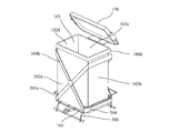
- FIG. 2 is a view showing the structure of the dust container 100 according to the first embodiment of the present disclosure.
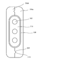
- FIG. 3 is a view showing the structure of the dust container 100 according to the first embodiment of the present disclosure.
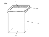
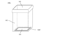
- FIG. 4a is a view showing a modified example of the structure of the dust container 100 according to the first embodiment of the present disclosure.
- FIG. 4 b is a view showing a modified example of the structure of the dust container 100 according to the first embodiment of the present disclosure.
- FIG. 4 c is a view showing a modified example of the structure of the dust container 100 according to the first embodiment of the present disclosure.
- FIG. 1 is a diagram showing a configuration of a waste detection system 1 according to a first embodiment of the present disclosure.
- FIG. 2 is a view showing the structure of the dust container 100 according to the first embodiment of the present disclosure.
- FIG. 3 is a view showing the structure
- FIG. 4 d is a view showing a modified example of the structure of the dust container 100 according to the first embodiment of the present disclosure.
- FIG. 5 is a block diagram showing the configuration of the waste detection system 1 according to the first embodiment of the present disclosure.
- FIG. 6 is a circuit diagram showing a circuit configuration of the waste detection system 1 according to the first embodiment of the present disclosure.
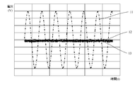
- FIG. 7a is a diagram showing an example of a waveform detected by the waste detection system 1 according to the first embodiment of the present disclosure.
- FIG. 7 b is a diagram showing an example of a waveform detected by the waste detection system 1 according to the first embodiment of the present disclosure.
- FIG. 7 c is a diagram showing an example of a waveform detected by the waste detection system 1 according to the first embodiment of the present disclosure.
- FIG. 8 is a view showing the structure of the gauze 400 according to the first embodiment of the present disclosure.
- FIG. 9 is a view showing the structure of the gauze 400 according to the first embodiment of the present disclosure.
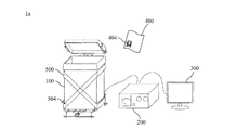
- FIG. 10 is a diagram showing a configuration of a waste detection system 1a according to a second embodiment of the present disclosure.
- FIG. 11 is a view showing the structure of the trash receptacle 100d and the rack 500 according to the second embodiment of the present disclosure.
- FIG. 12 is a view showing the structure of the rack 500 according to the second embodiment of the present disclosure.
- FIG. 13 is a view showing the structure of the rack 500 according to the second embodiment of the present disclosure.
- FIG. 14 a is a view showing a modified example of the structure of the rack 500 according to the second embodiment of the present disclosure.
- FIG. 14 b is a view showing a modified example of the structure of the rack 500 according to the second embodiment of the present disclosure.
- FIG. 14 c is a view showing a modified example of the structure of the rack 500 according to the second embodiment of the present disclosure.
- FIG. 15 is a circuit diagram showing a circuit configuration of a waste detection system 1b according to a third embodiment of the present disclosure.
- FIG. 16a is a diagram showing an example of a waveform detected by the waste detection system 1 according to the third embodiment of the present disclosure.
- FIG. 16 b is a diagram showing an example of a waveform detected by the waste detection system 1 according to the third embodiment of the present disclosure.
- the waste detection system according to the present disclosure relates to a system capable of detecting that a waste container is charged with a specific waste.
- the system is applicable, although it is not limited to the following, medical sites for treating patients and surgery, construction sites for construction and construction, vehicles such as cars and airplanes, precision Equipment, clothing, etc. production, repair, maintenance site, etc. may be mentioned. That is, the present invention can be suitably applied to a site where various problems will occur if it is accidentally discarded or taken out unnecessarily.
- Such a waste detection system may, for example, be a waste container, an analyzer connected to the waste container, an alarm device (such as a display or a speaker) to notify that a specific item has been inserted, and in some cases, Includes a rack to support the waste container.
- the waste detection system which has such a configuration equips a refuse container or a rack with a sensor, analyzes the output from the sensor concerned with an analysis device, and detects that a specific article was thrown into a refuse container . Furthermore, the said waste detection system alert
- waste refers to an article that can be thrown into the waste container regardless of whether or not it is actually discarded after being put into the waste container. That is, for example, it may be moved to another place without being actually put into the waste container, an article which may be unintentionally or intentionally put into the waste container, or put into the waste container but not actually disposed of. Such items may also be included in the waste.
- Examples of articles detected by such a waste detection system according to the present disclosure include medical gauze, medical equipment such as energy devices used in syringes, and surgery, construction sites, manufacturing, repair, maintenance, etc. Tools etc. used for The above is merely an example, and the waste detection system can be suitably applied to any item that causes various problems if it is discarded by mistake or taken out unnecessarily.
- an antenna element such as a coil antenna is prearranged in order to be detectable in the sensor and analysis device. Then, when an article in which the antenna element is disposed in advance passes through the dust container, the change in the magnetic field generated by a sensor such as a coil disposed in advance in the dust container is analyzed by an analyzer and the article is inserted. Detect what has been done. Thus, for example, it is possible to notify the user that an article which should not have been discarded into the waste container has been accidentally inserted into the waste container.
- First Embodiment 1 Overview of waste detection system 1 according to the first embodiment
- the waste detection system 1 according to the first embodiment relates to a medical waste detection system capable of detecting that medical gauze has been loaded into a medical waste container. .
- FIG. 1 is a diagram showing a configuration of a waste detection system 1 according to a first embodiment of the present disclosure.
- the waste detection system 1 includes a dust container 100 in which the detection sensor 104 is disposed, and an analyzer 200 and an analyzer 200 communicably connected to the detection sensor 104 of the dust container 100 wirelessly or by wire. It includes a display 300 communicably connected wirelessly or by wire.
- the waste detection system detects, with the detection sensor 104, a change in the magnetic field due to the medical gauze 400 in which the article-side coil 404 is disposed being inserted into the dust container 100, and transmits the output to the analysis device 200.
- the analysis device 200 detects that the medical gauze 400 has been inserted based on the received output.
- FIG. 2 is a view showing the structure of the garbage container 100 according to the first embodiment of the present disclosure. Specifically, an example of the configuration of the dust container 100 used in the waste detection system 1 according to the first embodiment is shown.
- the waste container 100 is formed by the bottom wall 101 constituting the bottom surface of the waste container 100, the side wall 102 erected upward from the peripheral edge 101a along the outer periphery of the bottom wall 101, and the upper portion of the side wall 102 It includes a main body container having an opening 103 into which an object is inserted, and a detection sensor 104 for detecting the insertion of the medical gauze 400.
- the waste container 100 may be made of any known material, for example, epoxy resin, phenol resin, polypropylene, polyethylene, polyvinyl chloride, polystyrene, ABS resin, polyamide, various resin materials such as polycarbonate, or those Manufactured from composite resin materials.
- the main container of the refuse container 100 has the bottom wall 101, the side wall 102, and the opening 103 as described above.
- the bottom wall 101 has a peripheral edge 101a composed of four sides on its outer periphery, and has a substantially square shape. Therefore, the side wall 102 has four side walls of a side wall 102a, a side wall 102b, a side wall 102c, and a side wall 102d corresponding to each side. And since the opening 103 is formed in the upper part by these four side walls 102a to 102d, the opening 103 also has a substantially square shape.
- the side walls 102a to 102d of the dust container 100 include a detection sensor 104 formed in a coil shape inside.
- the detection sensor 104 is a side wall 102 a from the lower left to the upper right, the upper left to the side wall 102 b from the upper right to the side wall 102 c, the upper left to the lower right
- a detection sensor coil 104a formed in an annular shape connecting the lower left portion to the lower right portion toward 102d, a lower left portion from the upper left portion toward the side wall 102a, a lower right portion from the lower left portion toward the side wall 102b
- a detection sensor coil 104b formed in an annular shape connecting the upper left portion to the upper right portion toward the side wall 102d.
- the detection sensor coil 104a and the detection sensor coil 104b are respectively disposed annularly along the entire circumference of the side walls 102a to 102d.
- the detection sensor coil 104a and the detection sensor coil 104b are disposed on the side walls 102a to 102d so that the dust container 100 intersects in a substantially X shape when viewed from the side.
- an alternating current voltage is applied from the oscillation device of the analysis device 200 connected to the outside, so that the detection sensor coil 104a has a current in the direction of arrow 107a and the detection sensor coil 104b has a current in the direction of arrow 107b.
- Flow and a magnetic field is generated which penetrates from the lower side of the refuse container 100 to the upper side. Therefore, when the surface on which the article-side coil 404 provided in the medical gauze 400 is formed becomes perpendicular to the magnetic field formed in the dust container 100, a change in the magnetic field is detected with sufficient sensitivity. Is possible.
- the direction of the generated magnetic field by 90 degrees by switching the current flowing in the detection sensor coil 104a and the detection sensor coil 104b in opposite directions at random or at fixed time intervals. Therefore, it is possible to detect a medical gauze that could not be detected with high sensitivity when a magnetic field that penetrates from the lower side to the upper side of the dust container 100 is formed. That is, by switching the direction of the current supplied to each of the detection sensor coils 104a and 104b at random or at fixed time intervals, the sensitivity substantially in two directions is obtained, and the detection performance is improved.
- the switching cycle is, for example, 10 msec to 1 sec.
- FIG. 3 is a view showing the structure of the dust container 100 according to the first embodiment of the present disclosure. Specifically, FIG. 3 is a cross-sectional view of a region of the side wall 102 of the dust container 100 in which the detection sensor coil 104a or 104b is disposed. According to FIG. 3, the side wall 102 includes therein a coil wire 104c wound a plurality of times, a fixing layer 108 covering the coil wire 104c, and a shield material 105 covering the coil wire 104c and the fixing layer 108. .
- the shielding material 105 uses a known shielding material for the purpose of reducing the influence of noise due to the electric field.
- the coil wire 104 c is preferably a magnet wire formed of a conductor such as copper, copper alloy, aluminum, gold, nickel, iron or the like.
- the fixed layer 108 can be formed of the same material as the side wall 102.
- the shield member 105 is formed apart from the coil thin line 104c by a fixed distance (for example, 1 cm).
- the coil thin wire 104c may be directly covered with the shield material 105 without forming the fixed layer 108 in particular.
- FIG. 4a, FIG. 4b and FIG. 4c are figures which show the modification of the structure of the refuse container 100 based on 1st Embodiment of this indication.
- FIG. 2 shows an example in which the detection sensor coil 104a and the detection sensor coil 104b are disposed along the entire circumference of the side wall 102 of the dust container, but FIG. The example in which the detection sensor coil 104d is arrange
- FIG. 4 b shows an example in which the detection sensor coil 104 e is disposed only on a part of the side wall 102, more specifically, one side wall (side wall 102 a) of the four side walls 102 a to 102 d.
- FIG. 4 c shows an example in which the detection sensor coil 104 f is disposed on the bottom wall 101.
- FIG. 2 is an example, and appropriately disposed in the dust container 100 according to the type, shape, shape of the article to be detected, the shape of the coil disposed in the article, the direction in which the article is inserted, etc.
- the detection sensor coil to be switched can be changed.
- FIG. 4 d is a view showing a modified example of the structure of the dust container 100 according to the first embodiment of the present disclosure.
- FIG. 3 shows the case where the detection sensor coil 104 is housed inside the side wall 102 of the dust container 100, but FIG. 4d shows that the inner surface or the outer surface of the side wall 102 is covered with the shield material 105. It shows about the case where the coil thin wire
- FIG. 4 d although it is on the inner surface or the outer surface of the side wall 102, it is of course possible to dispose on the inner surface or the outer surface of the bottom wall 101.
- the bottom wall 101 is described as having a substantially rectangular shape in the example of FIG. 2 and the examples of FIGS. 4a to 4c, any shape such as a circle, triangle, pentagon, hexagon, or more may be used.
- the side wall 102 is not limited to the four side walls, and may be formed in a cylindrical shape, or may have a plurality of two or more side walls.
- the opening 103 may have any shape, such as a circle, a triangle, a pentagon, a hexagon, or a polygon corresponding to the shapes and numbers of the bottom wall 101 and the side walls 102.
- the entire shape thereof does not have to be formed in a substantially columnar shape, and may have any shape such as a cone shape, a frustum shape, a mortar shape, and a spherical shape.
- such a waste container 100 can be suitably applied regardless of its capacity from small-sized ones with a capacity of 10 L or less, medium-sized ones of 10 L to 40 L, and large-sized ones with 40 L or more. it can.
- FIG. 5 is a block diagram showing a configuration of the waste detection system 1 according to the first embodiment of the present disclosure.
- the waste detection system 1 includes the dust container 100, the analyzer 200, and the display 300, and is connected to each other by wire or wireless so as to transmit and receive various signals, instruction commands, data, and the like.
- the analysis device 200 at least includes a memory 201, a processor 202, an input interface 203, a detection circuit 204, and an I / O circuit 205, and the respective constituent elements are electrically connected to each other through data lines.
- the analysis apparatus 200 does not have to include all of the components shown in FIG. 5, and may have a configuration in which a part is omitted, and other components may be added. Further, the analysis device 200 can also be distributed to a plurality of devices to arrange each component.
- the memory 201 includes a ROM, a RAM, a non-volatile memory, an HDD, and the like, and functions as a storage unit.
- the ROM stores instruction commands for executing analysis processing and the like according to the present embodiment and a predetermined OS as a program.
- the RAM is a memory used to write and read data while the program stored in the ROM is being processed by the processor 202.
- the non-volatile memory and the HDD are memories in which writing and reading of data are executed by the execution of the program, and the data written in the memory is saved even after the execution of the program is completed.
- the nonvolatile memory and the HDD store, for example, various setting values such as a voltage value applied to the detection sensor circuit, parameter values, various detected analysis values, and the like.
- the processor 202 is constituted of a CPU (microcomputer: microcomputer) as an example, and executes an instruction command (program) stored in the memory 201 to function as a control unit for controlling other connected components. .
- the processor 202 executes various analysis processing programs stored in the memory 201 to detect whether or not a specific item is thrown into the trash container 100, and notifies the detection on the display 300. Take control.
- the processor 202 may be configured by a single CPU, but may be configured by a plurality of CPUs. Also, other types of processors such as a GPU specialized for image processing may be combined as appropriate.
- the input interface 203 includes a touch panel and / or a hard key, and functions as an operation unit that receives various instructions and inputs from the user.
- the input interface 203 is used to turn on / off the analysis device 200 and set the display of the display 300.
- the detection circuit 204 forms a detection circuit together with the detection sensor 104 (detection sensor coils 104a and 104b) disposed in the dust container 100, and inputs the medical gauze 400 on which the article side coil 404 is disposed to the dust container 100. Detect The specific configuration of the detection circuit will be described later.
- the I / O circuit 205 is connected to the I / O circuit of the display 300, and functions as an information input / output unit for inputting / outputting information between the analysis device 200 and the display 300. Specifically, the I / O circuit 205 transmits, to the display 300, information for notifying the insertion of a specific item based on the control of the processor 202.
- the display 300 was described as an alarm device, it is not restricted only to the said display 300.
- a speaker may be provided as an alarm device, and the input may be notified by sound.
- a light emitting device such as an LED may be provided as an alarm device, and the switch may be notified of light emission.
- a vibration device may be provided as an alarm device, and the introduction may be notified by vibration.
- the alarm device may be connected wirelessly, the detection of the insertion may be notified to a wireless terminal such as a smart phone connected wirelessly, and the display, the speaker, and the vibration device of the portable terminal may be notified of the insertion. That is, in this case, it is also possible to use a portable terminal as an alarm device.
- FIG. 6 is a circuit diagram showing a circuit configuration of a waste detection system 1 according to a first embodiment of the present disclosure. Specifically, in FIG. 6, the detection circuit on the analysis device 200 side and the detection circuit (detection sensor 104) on the dust container 100 side are electrically connected to each other to form one detection circuit. 2 shows a circuit configuration of the detection circuit.
- the detection circuit includes a bridge circuit including an oscillation device 206, a plurality of variable resistors 211, and a resonance device 216 including a detection sensor coil 104a or 104b and a capacitor (not shown), an amplification device 207, at least including multiplying devices 208a and 208b, and rectifying devices 209a and 209b, and the respective components are electrically connected to each other.
- an alternating voltage is applied to the bridge circuit by the oscillation device 206 based on the setting information of the analysis device stored in the memory 201.
- the frequency of the alternating voltage to be applied is a frequency that can resonate with the resonance frequency of the detection sensor coil 104a or 104b included in the bridge circuit.
- the frequency of the applied alternating voltage is the same as or substantially the same as the resonance frequency of the detection sensor coil 104a or 104b.
- it is desirable that the frequency of the applied AC voltage is 0.1 MHz to 20 MHz, preferably 0.5 MHz to 5 MHz, more preferably 0.5 MHz to 1 MHz.
- the frequency may be appropriately determined in consideration of the balance between the sizes of the detection sensor coils 104a and 104b and the absorption of the electromagnetic wave by the living tissue.
- the detection circuit shown in FIG. 6 when an AC voltage is applied to the bridge circuit by the oscillator 206 having the above configuration, a current flows through the detection sensor coil 104a or 104b to generate an AC magnetic field (magnetic field).
- the article-side coil 404 disposed in the medical gauze 400 has a resonant frequency that can resonate with the detection sensor coil 104a or 104b. Therefore, when such a medical gauze is thrown into the refuse container 100, the magnetic field formed by the detection sensor coil 104a or 104b changes. By detecting this change using a circuit following the latter stage, the placement of the medical gauze 400 is detected.
- an alternating current signal obtained from a bridge circuit including the detection sensor coil 104a or 104b is amplified through the amplification device 207 and then multiplied by the alternating current voltage generated by the oscillation device 206.
- multiplication device 208a and multiplication device 208b two multiplication devices used at this time are prepared: multiplication device 208a and multiplication device 208b, and alternating current signals multiplied by respective multiplication devices 208a and 208b are transmitted to rectification devices 209a and 209b and converted into direct current signals
- a path passing through the multiplying device 208a and the rectifying device 209a is referred to as a path 21, and a path passing through the multiplying device 208b and the rectifying device 209b is referred to as a path 22.
- the rectifying device 209a detects only one of the positive peak value and the negative peak value of the amplitude of the AC electric signal after multiplication that has been determined in advance (in the example of FIGS.
- the rectifying device 209b After performing processing of inverting "positive” and “negative”, only one of them determined in advance is detected ("positive" peak value in the example of FIGS. 7a to 7c), Convert to DC signal.
- the converted direct current signals are output from the ports to which the paths 21 and 22 are respectively connected, and stored in the memory 201 for subsequent analysis.
- the variable resistor 211 is disposed on the ground side, but may be disposed on the output side of the oscillation device 206.
- one resonance circuit 216 is disposed in the bridge circuit, a plurality of resonance circuits may be disposed.
- two stages of a path 21 passing through the multiplying device 208 a and the rectifying device 209 a and a path 22 passing the multiplying device 208 b and the rectifying device 209 b are configured at a stage subsequent to the amplifying device 207.
- FIG. 7A shows the AC voltage waveform 11 applied by the oscillation device 206 when nothing is detected by the detection sensor 104 disposed in the dust container 100 of the waste detection system 1 (in a normal state).
- 3 shows an AC voltage waveform 12 output from the bridge circuit and an AC voltage waveform 13 output from the rectifier 209 a or 209 b.
- 7b shows the AC voltage waveform 11 applied by the oscillation device 206, the AC voltage waveform 12 output from the bridge circuit, and the rectifier when the medical gauze 400 in which the article side coil 404 is disposed is inserted.
- the alternating voltage waveform 13 output from 209a is shown.
- FIG. 7c shows an AC voltage waveform 11 applied by the oscillation device 206, an AC voltage waveform 12 output from the bridge circuit, and a rectifier when another medical device having at least a part of metal is inserted.
- the alternating voltage waveform 13 output from 209b is shown.
- the magnetic field formed by the detection sensor coil 104a or 104b substantially changes in the phase due to the change due to the resonance with the article side coil 404.
- the amplitude of the AC voltage waveform 12 output from the bridge circuit is increased.
- the processor 201 stores, in the memory 201, the fact that the “positive” output value has been received from the port of the path 21.
- the output from the multiplication circuit 208b is inverted and then becomes a "negative" value, so that it is not output from the rectification circuit 209b. That is, the analysis device 200 enables detection of the medical gauze 400 having the article-side coil 404 by detecting that the “positive” output value has been received from the port of the path 21.
- FIG. 7c compared to the normal state (FIG. 7a), when a medical device containing metal at least in part is inserted, the oscillation device is affected by the eddy current flowing in the metal portion.
- the waveform of the AC voltage waveform 11 applied at 206 With respect to the waveform of the AC voltage waveform 11 applied at 206, a phase shift occurs in the phase of the AC voltage waveform 12 output from the bridge circuit.
- the phase of the AC voltage waveform 12 is shifted by 180 degrees with respect to the AC voltage waveform 11. Therefore, the output from the multiplying device 208b is inverted and then becomes a "positive" value, and the rectifying device 209b outputs a "positive" value (AC voltage waveform 13).
- the output from the multiplication circuit 208a has a "negative" value due to a phase shift, and therefore is not output from the rectification circuit 209a. That is, the analysis device 200 detects that the medical device containing metal is inserted by detecting that the value of “positive” is received from the port of the path 22. That is, when the medical gauze 400 is inserted, the output from the port of the path 21 is detected, but when the medical device containing metal is inserted, the output from the port of the path 22 is detected The difference in the port from which this signal is output makes it possible to detect that the medical device containing metal is inserted, as distinguished from the medical gauze 400 having the article-side coil 404.
- the bridge circuit be kept in balance. Therefore, feedback is applied under the control of the processor 202 based on the DC signal stored in the memory 201, and the oscillation frequency of the oscillation device 206, the resonance frequency of the detection sensor coil 104a or 104b, and the resistance value of the variable resistor 211 included in the bridge circuit. It is possible to control various setting values such as to maintain an equilibrium state.
- both "positive” and “negative” alternating voltage waveforms will be obtained simultaneously. Therefore, they mutually cancel each other, and there is a possibility that the input of the medical gauze 400 or the like in which the article-side coil 404 is disposed can not be detected.
- a reference coil may be newly provided separately from the detection sensor coil 104a or 104b, or the capacitance value of a capacitor included in the resonance device 216 may be changed to change the resonance frequency.
- a DC signal is obtained from the detection coil or the detection sensor coil 104a or 104b whose resonance frequency has been changed. Then, based on the obtained direct current signal, the oscillation frequency of the oscillation device 206, the detection sensor coil 104a, such that the direct current signal obtained from the other medical device including metal by the processor 202 approaches zero as much as possible.
- various setting values such as the resonance frequency of 104 b and the resistance value of the variable resistor 211 included in the bridge circuit are controlled. Thereby, even when the article coil 404 and the metal are simultaneously present, they can be distinguished and detected.
- FIG. 8 is a view showing the structure of the gauze 400 according to the first embodiment of the present disclosure.
- the medical gauze 400 has a film 402 covering the substrate 403, the article side coil 404 disposed on the substrate 403, the substrate 403 and the article side coil 404 on the surface of the gauze main body 401. Be placed.
- the gauze main body 401 of the medical gauze 400 is manufactured, for example, by weaving at regular intervals so as to alternately cross a warp yarn and a weft yarn made of, for example, a No. 40 cotton yarn.
- a weft yarn made of, for example, a No. 40 cotton yarn.
- the material of the yarn is not limited to cotton yarn, and cellulose fiber, synthetic fiber, or a combination thereof may be used.
- the gauze main body 401 in order to detect the residue of the medical gauze 400 by X-ray, it is also possible to braid an X-ray contrast yarn in part thereof. It is possible to use a synthetic resin fiber containing a material impermeable to X-rays such as barium sulfate as the X-ray contrast yarn. It is possible to utilize well-known materials, such as a silicon system, a polyvinyl chloride, a polypropylene, polyester, polyethylene, a styrene system, as a synthetic resin.
- the article-side coil 404 is made of a conductor such as copper, copper alloy, aluminum, gold, nickel, iron or the like, and is formed annularly along the outer periphery of the substrate 403.
- the substrate 403 is made of a known insulating film.
- the insulating film for example, polyimide, polyethylene terephthalate, polytetrafluoroethylene or the like can be used.
- any film may be used as the film 402 as long as it can protect the inside of the article coil 404 from moisture, dust, etc.
- materials such as polyvinyl chloride, silicone, polyolefin, polytetrafluoroethylene, etc. are used.
- FIG. 9 is a view showing the structure of a medical gauze 400 according to the first embodiment of the present disclosure. Specifically, FIG. 9 shows a cross-sectional view of a region of the medical gauze 400 including the article-side coil 404.
- the film 402b is disposed on the upper surface of the gauze body 401. Then, on the film 402b, the substrate 403 and the article side coils 404a and 404b disposed on both sides thereof are disposed.
- the article coils 404a and 404b are configured to be electrically connected to each other through through holes (not shown) provided in the substrate 403.
- the film 402a is disposed so as to cover the substrate 403 and the article side coils 404a and 404b, and the respective ends of the films 402a and 402b and the gauze main body 401 are adhered to each other by a known method. Further, the film 402c is adhered to the lower surface of the gauze main body 401 at a position corresponding to the film 402b by a known method. Thus, it is possible to prevent moisture, dust, and the like from entering the space where the substrate 403 and the article-side coils 404a and 404b are disposed.
- the waste detection system 1 it is possible to provide a waste container capable of managing the fact that a specific article has been inserted into the waste container by a simpler method. Specifically, it is possible to detect that a specific article has been thrown into the waste container and to notify via an alarm device such as a display or a speaker. Moreover, it becomes possible to distinguish and detect the case where a specific article is put into the waste container and the case where another article is put into the waste container.
- the waste detection system 1 using the dust container 100 in which the detection sensor 104 is disposed has been described.
- the waste sensor 100 is not disposed in the dust container 100, and the waste detection system 1a in which the detection sensor 504 is disposed in the rack 500 for supporting the dust container 100 will be described.
- the present embodiment is the same as the configuration, processing, and procedure in the first embodiment, except for the points specifically described below. Therefore, detailed description of those matters is omitted.
- FIG. 10 is a diagram showing a configuration of a waste detection system 1a according to a second embodiment of the present disclosure.
- the waste detection system 1a is an analysis in which the dust container 100, the detection sensor 504 are disposed, the rack 500 for supporting the dust container 100, and the detection sensor 504 are communicably connected by radio or wire.
- the apparatus 200 includes a display 300 communicably connected to the analysis apparatus 200 wirelessly or by wire.
- the said waste detection system 1a detects the change of the magnetic field by the medical gauze 400 in which the article side coil 404 was arrange
- Send to The analysis device 200 detects that the medical gauze 400 has been inserted based on the received output.
- FIG. 11 is a view showing the structure of the trash receptacle 100d and the rack 500 according to the second embodiment of the present disclosure.
- the waste container 100d is formed by the bottom wall 101 constituting the bottom surface of the waste container 100, the side wall 102 erected upward from the peripheral edge 101a along the outer periphery of the bottom wall 101, and the upper portion of the side wall 102 And a main body container having an opening 103 into which an object is charged. That is, except for the point that the detection sensor 104 is not included, the same configuration as the dust container 100 according to the first embodiment described in FIG. 2 and the like can be employed.
- the refuse container 100d is mounted on, for example, a support surface of the rack 500 and used as shown in FIG.
- the detection sensor 504 includes two sensor coils of a detection sensor coil 504a and a detection sensor coil 504b, and is configured to intersect the rack 500 in a substantially X shape when viewed from the side.
- the detection sensor coils 504a and 504b are disposed at positions overlapping the outer circumferences of the side walls 102a to 102d of the dust container 100d when the dust container 100d is placed.
- the dust container 100d can be provided with a lid 106 for covering the opening 103 (the dust container 100 according to the first embodiment can also be provided in the same manner). ).
- FIG. 12 is a view showing the structure of the rack 500 according to the second embodiment of the present disclosure.
- the rack 500 is formed by bending or welding a stainless steel or aluminum round bar having a certain rigidity.
- a pair of rod-like support rods 511 are provided at positions in contact with the floor surface.
- four round bars are bent at substantially the same length so as to be substantially parallel to form a support 501.
- the bottom wall 101 of the waste container 100 is placed on the support 501.
- the rack 500 also has an opening and closing mechanism for opening and closing the lid 106 of the dust container 100.
- the opening and closing mechanism is formed in a flat plate shape and is pivotally supported in a substantially central position in the vertical direction so as to be vertically tiltable, a pedal 502 installed on one end side of the coupling plate 512, and both ends of a lid 106 Connect the clips 503a and 503b for gripping, the arm 514 connected to the link mechanism 515 with both clips 503a and 503b installed at both ends and connected to the link mechanism 515 at the approximate center, and the link mechanism 515 and the other end of the connection plate 512 And a link rod 513 for transmitting the depression of the pedal 502 to the arm.
- the pedal 502 when the user depresses the pedal 502, the arm 514 and the clips 503a and 503b rotate upward. That is, when the lid 106 is gripped by the clips 503a and 503b, the lid 106 is opened and closed upward by the upward rotation.
- the rack 500 also includes detection coil sensors 504a and 504b arranged to intersect the rack 500 in a substantially X shape when viewed from the side.
- the detection coil sensors 504 a and 504 b are fixed to each other, and are also fixed to the round bars forming the rack 500.
- FIG. 13 is a view showing the structure of the rack 500 according to the second embodiment of the present disclosure. Specifically, FIG. 13 shows a cross-sectional structure of the detection sensor 504 (detection coil sensors 504 a and 504 b) of the rack 500.
- each of the detection sensor coils 504 a and 504 b includes a pair of cases 506 a and 506 b, a coil thin wire 505 wound around multiple times, a fixed layer 516 covering the coil thin wire 505, a coil thin wire 505 and a fixed layer And 516 include a shielding material 508 for covering and reducing the influence of noise due to the electric field.
- the cases 506a and 506b have recesses 509 and protrusions 510 at corresponding positions, respectively, and are fixed to each other by fitting and bonding them.
- known materials can be used for the cases 506a and 506b.
- various resin materials such as epoxy resin, phenol resin, polypropylene, polyethylene, polyvinyl chloride, polystyrene, ABS resin, polyamide, polycarbonate and the like, or composites thereof Manufactured from a resin material.
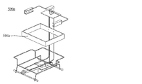
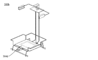
- FIGS. 14a, 14b, and 14c are diagrams showing modifications of the structure of the rack 500 according to the second embodiment of the present disclosure.
- FIG. 12 shows an example in which the detection sensor coils 504 a and 504 b are arranged in a substantially X shape at a position overlapping the side wall 102 of the dust container 100.
- FIG. 14a shows an example in which the detection sensor coil 504c is disposed at a position corresponding to the upper portion of the side wall 102 of the dust container 100 so as to overlap the upper portion.
- FIG. 14 b shows an example in which a detection sensor coil 504 d is disposed at a position corresponding to the bottom wall 101 of the dust container 100 so as to overlap the bottom wall 101.
- 14c shows an example in which the detection sensor coil 504e is disposed at a position corresponding to only one of the side walls 102 of the dust container 100 so as to overlap only on the side wall.
- FIG. 12 is an example, and is appropriately arranged in the rack 500 according to the type, shape, and shape of the article to be detected, the shape of the coil disposed in the article, the direction in which the article is inserted, etc.
- the detection sensor coil can be changed.
- the waste detection system 1a it is possible to provide a rack for a waste container that can manage the fact that a specific article has been inserted into the waste container by a simpler method. Specifically, it is possible to detect that a specific article has been thrown into the waste container and to notify via an alarm device such as a display or a speaker. Moreover, it becomes possible to distinguish and detect the case where a specific article is put into the waste container and the case where another article is put into the waste container.
- the waste detection systems 1 and 1a according to the first and second embodiments use a multiplying device to input the medical gauze 400 in which the article-side coil 404 is disposed, and input other medical articles including metal. Detection by detecting the phase shift.
- the insertion of the medical gauze 400 in which the article-side coil 404 is disposed, and the introduction of other medical articles including metal are out of phase using an exclusive OR (XOR) circuit.
- XOR exclusive OR
- the waste detection system 1b which detects by detecting is demonstrated.
- the present embodiment is the same as the configuration, processing, and procedure in the first embodiment, except for the points specifically described below. Therefore, detailed description of those matters is omitted.
- FIG. 15 is a circuit diagram showing a circuit configuration of a waste detection system 1b according to a third embodiment of the present disclosure. Specifically, an exclusive OR circuit used in place of the amplification device 207 shown in FIG. Referring to FIG. 15, the AC voltage signal 212a output from the bridge circuit of FIG. 6 and the AC voltage signal 212b applied from the oscillation device 206 of FIG. 6 are input to the comparators 213a and 213b, respectively. At this time, the comparators 213a and 213b convert the input alternating voltage signals 212a and 212b into on / off signals by comparison with the reference voltage. The changed signals are input to the exclusive OR circuit 214, respectively.
- the exclusive OR circuit 214 When there is a phase shift between the two input signals, the exclusive OR circuit 214 outputs an ON signal while the phase shift is occurring, and outputs the signal if there is no phase shift. Not performed. Then, the output signal is converted to a DC signal through the low pass filter 215 and stored in the memory 201.
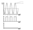
- FIG. 16a and 16b are diagrams showing examples of waveforms detected by the waste detection system 1 according to the third embodiment of the present disclosure.
- FIG. 16a shows a signal waveform when the medical gauze 400 having the article side coil 404 is inserted into the trash can
- FIG. 16b shows a signal waveform when the medical device containing metal is inserted into the trash can. Show.
- the signal waveform of the state in which neither the medical gauze 400 nor the medical equipment containing a metal is thrown in is not shown in figure. In such a state, for example, as exemplified by the AC voltage waveform 12 of FIG. 7a, the AC voltage signal from the bridge circuit becomes very small.
- the processor 202 first confirms the amplitude of the AC voltage signal from the bridge circuit, and if it does not exceed the predetermined amplitude width, neither the medical gauze 400 nor the medical device containing metal is inserted. Judge that it is a state. On the other hand, when the amplitude of the AC voltage signal from the bridge circuit exceeds the predetermined amplitude width, the processor 202 determines that either the medical gauze 400 or the medical device containing metal is inserted. , Detection by the phase shift described in FIGS. 16a and 16b.
- FIG. 16a shows the signal waveform when the medical gauze 400 having the article-side coil 404 is thrown into the trash can, as described above.
- FIG. 16 b shows the signal waveform when the medical device containing metal is thrown into the trash as described above.
- the amplitude 12 of the AC voltage signal 212a output from the bridge circuit is out of phase with the amplitude 11 of the AC voltage signal 212b applied from the oscillation device 206.
- the phase shift is detected also in the signal waveforms output from the comparators 213a and 213b, and as shown in the lower graph of FIG. The on signal according to is output.
- the signal output from the exclusive OR circuit 214 transitions without being turned on. In other words, it is possible to detect that the medical gauze 400 has been thrown into the trash container 100 by detecting that the signal has transitioned without being turned on.
- the ON signal is continuously output from the exclusive OR circuit 214 because a phase shift occurs. That is, by detecting that the on signal is continuously output, it is possible to detect that the medical device having metal is inserted into the dust container 100.
- the waste detection system 1a it is possible to provide a rack for a waste container that can manage the fact that a specific article has been inserted into the waste container by a simpler method. Specifically, it is possible to detect that a specific article has been thrown into the waste container and to notify via an alarm device such as a display or a speaker. Moreover, it becomes possible to distinguish and detect the case where a specific article is put into the waste container and the case where another article is put into the waste container.
- a coil is used as the detection sensor 104 or 504 to detect insertion of an article on which the article-side coil 404 is disposed.
- the present invention is not limited to this, and the insertion of a specific article may be detected using an antenna or the like.
- the article side coil 404 is disposed not only on medical gauze but also on medical equipment such as energy devices used in syringes, surgery etc., tools used in construction sites and manufacturing / repair / maintenance etc. It is possible to detect the input to the waste container. Note that the above is merely an example, and the article side coil 404 can be suitably applied to any article that causes various problems if it is discarded by mistake or taken out unnecessarily.
- the phase shift of the detection sensor coil 104 or 504 is detected in the analyzer 200 using the multipliers 208 a and 208 b.
- the phase shift is detected using the exclusive OR circuit 214.
Landscapes
- Engineering & Computer Science (AREA)
- Mechanical Engineering (AREA)
- Accommodation For Nursing Or Treatment Tables (AREA)
- Refuse Receptacles (AREA)
- Refuse Collection And Transfer (AREA)
- Investigating Or Analyzing Materials By The Use Of Magnetic Means (AREA)
Abstract
Description
本開示に係る廃棄物検出システムは、ゴミ容器に特定の廃棄物が投入されたことを検出可能なシステムに関する。当該システムが適用可能な例としては、以下にあげるものに限定するものではないものの、患者の治療や手術等を行う医療現場、工事や建築等を行う工事現場、車や飛行機等の車両、精密機器、衣類等の製造・修繕・メンテナンス現場などが挙げられる。すなわち、誤って廃棄されたり、不要な持ち出しがなされてしまうと様々な問題を引き起こすような現場において、好適に適用することができる。
1.第1実施形態に係る廃棄物検出システム1の概要
第1実施形態に係る廃棄物検出システム1は、医療用ガーゼが医療用ゴミ容器に投入されたことを検出可能な医療用廃棄物検出システムに関する。
図2は、本開示の第1実施形態に係るゴミ容器100の構造を示す図である。具体的には、第1実施形態に係る廃棄物検出システム1に用いられるゴミ容器100の構成の例を示す。図2によると、ゴミ容器100は、ゴミ容器100の底面を構成する底壁101、底壁101の外周に沿った周縁101aから上方に立設された側壁102、側壁102の上部により形成され廃棄物が投入される開口103を有する本体容器と、医療用ガーゼ400の投入を検出するための検出センサ104とを含む。
図5は、本開示の第1実施形態に係る廃棄物検出システム1の構成を示すブロック図である。既に説明したとおり、廃棄物検出システム1は、ゴミ容器100、解析装置200、ディスプレイ300を含み、互いに各種信号、指示命令、データ等を送受信可能に有線又は無線で接続されている。
図6は、本開示の第1実施形態に係る廃棄物検出システム1の回路構成を示す回路図である。具体的には、図6は、解析装置200側の検出回路と、ゴミ容器100側の検出回路(検出センサ104)とが互いに電気的に接続されて一つの検出回路を形成しているが、当該検出回路の回路構成を示す。
本実施形態においては、検出される特定の物品として、物品側コイル404が配置された医療用ガーゼ400を例に挙げた。図8は、本開示の第1実施形態に係るガーゼ400の構造を示す図である。図8によると、医療用ガーゼ400は、そのガーゼ本体401の表面に、基板403と、基板403上に配置された物品側コイル404と、基板403及び物品側コイル404とを被覆するフィルム402が配置される。
第1実施形態では、検出センサ104が配置されたゴミ容器100を用いた廃棄物検出システム1について説明した。しかし、第2実施形態では、ゴミ容器100には検出センサ104は配置されず、ゴミ容器100を支持するためのラック500に検出センサ504が配置された廃棄物検出システム1aについて説明する。なお、本実施形態は、以下で具体的に説明する点を除いて、第1実施形態における構成、処理、手順と同様である。したがって、それらの事項の詳細な説明は省略する。
第1及び第2実施形態に係る廃棄物検出システム1及び1aでは、物品側コイル404が配置された医療用ガーゼ400の投入、及び金属を含む他の医療用物品の投入を、乗算装置を用いて位相ずれを検出することにより検知した。しかし、第3実施形態では、物品側コイル404が配置された医療用ガーゼ400の投入、及び金属を含む他の医療用物品の投入を、排他的論理和(XOR)回路を用いて位相ずれを検出することにより検知する廃棄物検出システム1bについて説明する。なお、本実施形態は、以下で具体的に説明する点を除いて、第1実施形態における構成、処理、手順と同様である。したがって、それらの事項の詳細な説明は省略する。
第1~第3実施形態においては、検出センサ104又は504としてコイルを用いて物品側コイル404が配置された物品の投入を検出した。しかし、これに限らず、アンテナ等を利用して特定の物品の投入を検知してもよい。
200 分析装置
300 警報装置
400 医療用ガーゼ
500 ラック
Claims (19)
- 底壁と、前記底壁の周縁から立設された側壁とを含み、前記側壁上部に形成された開口より投入された所定の廃棄物を内部に収容可能な本体容器と、
前記底壁及び前記側壁の少なくとも一つに配置され、医療用廃棄物の投入を検出するための検出センサと、
を含む医療用ゴミ容器。 - 前記検出センサは、前記底壁に配置される、請求項1に記載の医療用ゴミ容器。
- 前記検出センサは、前記側壁に配置される、請求項1に記載の医療用ゴミ容器。
- 前記検出センサは、前記側壁の全周に沿って配置される、請求項1に記載の医療用ゴミ容器。
- 前記底壁は四角形状に形成され、
前記側壁は、四角形状に形成された前記底壁の各辺から立設された第1~第4の側壁を含み、
前記検出センサは、前記第1~第4の側壁の全てに沿って配置される、請求項1に記載の医療用ゴミ容器。 - 前記検出センサは、第1のコイルを含む、請求項1~5のいずれか一項に記載の医療用ゴミ容器。
- 前記第1のコイルは、0.1MHz~20MHzの共振周波数を有する、請求項6に記載の医療用ゴミ容器。
- 前記検出センサは、第2のコイルを含む第1の医療用廃棄物が投入されたことを検知するための解析装置に接続される、請求項1~7のいずれか一項に記載の医療用ゴミ容器。
- 前記検出センサは、前記第2のコイルを含まない第2の医療用廃棄物が投入されたことを、前記第1の医療用廃棄物が投入されたこととは区別して検知するための解析装置に接続される、請求項8に記載の医療用ゴミ容器。
- 前記第1の医療用廃棄物は、医療用ガーゼである、請求項8又は9に記載の医療用ゴミ容器。
- 前記第2の医療用廃棄物は、その少なくとも一部に金属を含む、請求項9に記載の医療用ゴミ容器。
- 請求項1~11のいずれか一項に記載の医療用ゴミ容器と、
前記医療用ゴミ容器に含まれる前記検出センサに接続された解析装置と、
前記解析装置に接続された警報装置と、
を含む、医療用廃棄物検出システム。 - 前記解析装置は、第2のコイルを含む第1の医療用廃棄物が投入されたことを検知する、請求項12に記載の医療用廃棄物検出システム。
- 前記解析装置は、前記第1の医療用廃棄物とは異なる第2の医療用廃棄物が投入されたことを、前記第1の医療用廃棄物が投入されたこととは区別して検知する、請求項13に記載の医療用廃棄物検出システム。
- 前記検出センサは前記第2のコイルと共振可能な共振周波数を有する第1のコイルを含み、
前記解析装置は、前記第1の医療用廃棄物が投入されることにより生じる磁界の変化を検知することにより、前記第1の医療用廃棄物が投入されたことを検知する、請求項13又は14に記載の医療用廃棄物検出システム。 - 前記解析装置は、前記第1のコイルの共振周波数に共振可能な周波数の交流電圧を前記第1のコイルに印加する発振回路を含み、
前記解析装置は、前記第2の医療用廃棄物が投入されることにより生じる、前記第1のコイルにより生成される交流電圧と、前記発振回路により印加された前記交流電圧との位相ずれを検知することにより、前記第2の医療用廃棄物が投入されたことを検知する、請求項15に記載の医療用廃棄物検出システム。 - 前記警報装置は、前記解析装置において検出された前記第1の医療用廃棄物の投入を示す表示を行う、請求項13~16のいずれか一項に記載の医療用廃棄物検出システム。
- 底壁、及び前記底壁の周縁から立設された側壁を含み、前記側壁上部に形成された開口より投入された所定の廃棄物を内部に収容可能な本体容器と、を含む医療用ゴミ容器を支持するためのラックであって、
前記ラックは、前記医療用ゴミ容器の前記底壁及び前記側壁の少なくとも一つに重畳するように配置され、医療用廃棄物の投入を検出するための検出センサと、
を含む、ラック。 - 請求項18に記載のラックと、
前記ラックに含まれる前記検出センサに接続された解析装置と、
前記解析装置に接続された警報装置と、
を含む、医療用廃棄物検出システム。
Priority Applications (4)
| Application Number | Priority Date | Filing Date | Title |
|---|---|---|---|
| CN201880087403.0A CN111629981A (zh) | 2018-01-24 | 2018-01-24 | 医疗用垃圾容器、用于医疗用垃圾容器的架及医疗用废弃物检测系统 |
| JP2019567446A JPWO2019146019A1 (ja) | 2018-01-24 | 2018-01-24 | 医療用ゴミ容器、医療用ゴミ容器のためのラック及び医療用廃棄物検出システム |
| PCT/JP2018/002132 WO2019146019A1 (ja) | 2018-01-24 | 2018-01-24 | 医療用ゴミ容器、医療用ゴミ容器のためのラック及び医療用廃棄物検出システム |
| KR1020207017220A KR20200108417A (ko) | 2018-01-24 | 2018-01-24 | 의료용 쓰레기 용기, 의료용 쓰레기 용기를 위한 랙 및 의료용 폐기물 검출 시스템 |
Applications Claiming Priority (1)
| Application Number | Priority Date | Filing Date | Title |
|---|---|---|---|
| PCT/JP2018/002132 WO2019146019A1 (ja) | 2018-01-24 | 2018-01-24 | 医療用ゴミ容器、医療用ゴミ容器のためのラック及び医療用廃棄物検出システム |
Publications (1)
| Publication Number | Publication Date |
|---|---|
| WO2019146019A1 true WO2019146019A1 (ja) | 2019-08-01 |
Family
ID=67395890
Family Applications (1)
| Application Number | Title | Priority Date | Filing Date |
|---|---|---|---|
| PCT/JP2018/002132 Ceased WO2019146019A1 (ja) | 2018-01-24 | 2018-01-24 | 医療用ゴミ容器、医療用ゴミ容器のためのラック及び医療用廃棄物検出システム |
Country Status (4)
| Country | Link |
|---|---|
| JP (1) | JPWO2019146019A1 (ja) |
| KR (1) | KR20200108417A (ja) |
| CN (1) | CN111629981A (ja) |
| WO (1) | WO2019146019A1 (ja) |
Cited By (2)
| Publication number | Priority date | Publication date | Assignee | Title |
|---|---|---|---|---|
| CN111703770A (zh) * | 2020-04-07 | 2020-09-25 | 西安汇智医疗集团有限公司 | 一种手术室专用的医疗垃圾智能管理系统 |
| CN113320854A (zh) * | 2021-07-07 | 2021-08-31 | 江西理工大学 | 一种非接触磁悬浮抓取式医疗废弃物收集搬运设备 |
Families Citing this family (1)
| Publication number | Priority date | Publication date | Assignee | Title |
|---|---|---|---|---|
| KR102395904B1 (ko) * | 2021-06-30 | 2022-05-09 | 안해심 | 의료 폐기물 수거 장치 |
Citations (5)
| Publication number | Priority date | Publication date | Assignee | Title |
|---|---|---|---|---|
| JPH0638980A (ja) * | 1992-07-22 | 1994-02-15 | N S D Kk | 手術用ガーゼおよびその使用管理装置 |
| JP2005121573A (ja) * | 2003-10-20 | 2005-05-12 | Japan Science & Technology Agency | ワイヤレス磁気マーカの位置および方向の検出方法およびそのシステム |
| JP2011521731A (ja) * | 2008-05-30 | 2011-07-28 | ストライカー・コーポレイション | 金属検出装置、予検出装置、および/またはバッグ引張機構を備える固形医療廃棄物を収集するための廃棄物収集システム |
| JP2014188122A (ja) * | 2013-03-27 | 2014-10-06 | Akita Prefectural Hospital Organization | 磁性体検出センサ、磁性体検出方法および磁性体検出装置 |
| JP5897901B2 (ja) * | 2011-12-28 | 2016-04-06 | 川本産業株式会社 | Rfidタグ付き衛生材料の検出装置 |
Family Cites Families (7)
| Publication number | Priority date | Publication date | Assignee | Title |
|---|---|---|---|---|
| US5659247A (en) * | 1994-03-10 | 1997-08-19 | Denver Dynamics, Inc. | Device for detecting metal objects passing through an opening |
| US6222450B1 (en) * | 2000-02-02 | 2001-04-24 | Denver Dynamics, Inc. | Metal detection device having improved support assembly |
| JP3730555B2 (ja) | 2001-10-04 | 2006-01-05 | 旭化成せんい株式会社 | 手術用ガーゼの製法 |
| DE102012107274A1 (de) * | 2012-08-08 | 2014-03-06 | Aesculap Ag | Einrichtung und Verfahren zum gleichzeitigen Identifizieren einer Vielzahl chirurgischer Instrumente |
| ITTV20120201A1 (it) * | 2012-10-23 | 2014-04-24 | Corrado Altinier | Sistema e metodo per validare un contenitore per rifiuti |
| CN103552788B (zh) * | 2013-11-07 | 2016-03-09 | 邱泽国 | 集群式垃圾自动识别总成及其自动分类垃圾桶 |
| US9637309B2 (en) * | 2015-07-31 | 2017-05-02 | Edison Nation Medical, Llc | Waste receptacle |
-
2018
- 2018-01-24 JP JP2019567446A patent/JPWO2019146019A1/ja active Pending
- 2018-01-24 CN CN201880087403.0A patent/CN111629981A/zh active Pending
- 2018-01-24 WO PCT/JP2018/002132 patent/WO2019146019A1/ja not_active Ceased
- 2018-01-24 KR KR1020207017220A patent/KR20200108417A/ko not_active Ceased
Patent Citations (5)
| Publication number | Priority date | Publication date | Assignee | Title |
|---|---|---|---|---|
| JPH0638980A (ja) * | 1992-07-22 | 1994-02-15 | N S D Kk | 手術用ガーゼおよびその使用管理装置 |
| JP2005121573A (ja) * | 2003-10-20 | 2005-05-12 | Japan Science & Technology Agency | ワイヤレス磁気マーカの位置および方向の検出方法およびそのシステム |
| JP2011521731A (ja) * | 2008-05-30 | 2011-07-28 | ストライカー・コーポレイション | 金属検出装置、予検出装置、および/またはバッグ引張機構を備える固形医療廃棄物を収集するための廃棄物収集システム |
| JP5897901B2 (ja) * | 2011-12-28 | 2016-04-06 | 川本産業株式会社 | Rfidタグ付き衛生材料の検出装置 |
| JP2014188122A (ja) * | 2013-03-27 | 2014-10-06 | Akita Prefectural Hospital Organization | 磁性体検出センサ、磁性体検出方法および磁性体検出装置 |
Cited By (3)
| Publication number | Priority date | Publication date | Assignee | Title |
|---|---|---|---|---|
| CN111703770A (zh) * | 2020-04-07 | 2020-09-25 | 西安汇智医疗集团有限公司 | 一种手术室专用的医疗垃圾智能管理系统 |
| CN113320854A (zh) * | 2021-07-07 | 2021-08-31 | 江西理工大学 | 一种非接触磁悬浮抓取式医疗废弃物收集搬运设备 |
| CN113320854B (zh) * | 2021-07-07 | 2022-05-27 | 江西理工大学 | 一种非接触磁悬浮抓取式医疗废弃物收集搬运设备 |
Also Published As
| Publication number | Publication date |
|---|---|
| KR20200108417A (ko) | 2020-09-18 |
| JPWO2019146019A1 (ja) | 2021-01-28 |
| CN111629981A (zh) | 2020-09-04 |
Similar Documents
| Publication | Publication Date | Title |
|---|---|---|
| WO2019146019A1 (ja) | 医療用ゴミ容器、医療用ゴミ容器のためのラック及び医療用廃棄物検出システム | |
| US7784468B2 (en) | Surgical implement detection system | |
| US10815053B2 (en) | Waste receptacle | |
| US20220115111A1 (en) | Hand-held spherical antenna system to detect transponder tagged objects, for example during surgery | |
| EP3064164B1 (en) | Hand-held dual spherical antenna system | |
| GB2273778A (en) | Cordless digitizer | |
| BR112015020441B1 (pt) | Dispositivo de identificação portátil de prevenção de retenção de objetos cirúrgicos com marcadores magnéticos | |
| US8798717B2 (en) | Patient support and/or transport means and magnetic resonance system | |
| CN101019006A (zh) | 感应传感器 | |
| SE521232C2 (sv) | Givare och metod för beröringsfri detektering av föremål | |
| AU2360299A (en) | Disposal container for detecting, distinguishing and counting objects | |
| EP2097001B1 (en) | Method and arrangement for influencing and/or detecting magnetic particles in a region of action | |
| HK40032927A (en) | Medical refuse container, rack for medical refuse container, and medical waste detection system | |
| US8264224B2 (en) | Detection of magnetic fields using nano-magnets | |
| JP2854108B2 (ja) | 導電材製物品の識別方法と装置 | |
| Ward et al. | Magnetic induction tomography of objects for security applications | |
| JP2513694B2 (ja) | 座標入力装置 | |
| WO2016027756A1 (ja) | 手術用吸収性物品、検出装置および検出方法 | |
| US20200127662A1 (en) | Inductive Touch Sensor and Method for Operating the Same | |
| Clark et al. | Surgical instrument loss control | |
| JP2001108756A (ja) | 注射針検知装置 |
Legal Events
| Date | Code | Title | Description |
|---|---|---|---|
| 121 | Ep: the epo has been informed by wipo that ep was designated in this application |
Ref document number: 18902848 Country of ref document: EP Kind code of ref document: A1 |
|
| ENP | Entry into the national phase |
Ref document number: 2019567446 Country of ref document: JP Kind code of ref document: A |
|
| ENP | Entry into the national phase |
Ref document number: 20207017220 Country of ref document: KR Kind code of ref document: A |
|
| NENP | Non-entry into the national phase |
Ref country code: DE |
|
| 122 | Ep: pct application non-entry in european phase |
Ref document number: 18902848 Country of ref document: EP Kind code of ref document: A1 |